JP5566333B2 - Construction machine control system - Google Patents
Construction machine control system Download PDFInfo
- Publication number
- JP5566333B2 JP5566333B2 JP2011106572A JP2011106572A JP5566333B2 JP 5566333 B2 JP5566333 B2 JP 5566333B2 JP 2011106572 A JP2011106572 A JP 2011106572A JP 2011106572 A JP2011106572 A JP 2011106572A JP 5566333 B2 JP5566333 B2 JP 5566333B2
- Authority
- JP
- Japan
- Prior art keywords
- engine speed
- state
- construction machine
- pump torque
- standard
- Prior art date
- Legal status (The legal status is an assumption and is not a legal conclusion. Google has not performed a legal analysis and makes no representation as to the accuracy of the status listed.)
- Expired - Fee Related
Links
- 238000010276 construction Methods 0.000 title claims description 36
- 230000008859 change Effects 0.000 claims description 68
- 239000010720 hydraulic oil Substances 0.000 claims description 45
- 239000000446 fuel Substances 0.000 claims description 33
- 239000012530 fluid Substances 0.000 claims description 8
- 230000005477 standard model Effects 0.000 description 29
- 238000010586 diagram Methods 0.000 description 7
- 238000006073 displacement reaction Methods 0.000 description 5
- 230000009467 reduction Effects 0.000 description 5
- 238000012937 correction Methods 0.000 description 4
- 230000003247 decreasing effect Effects 0.000 description 4
- 238000002347 injection Methods 0.000 description 4
- 239000007924 injection Substances 0.000 description 4
- 238000004891 communication Methods 0.000 description 3
- 230000008602 contraction Effects 0.000 description 3
- 230000000694 effects Effects 0.000 description 3
- 230000010365 information processing Effects 0.000 description 3
- 238000004519 manufacturing process Methods 0.000 description 3
- 239000003921 oil Substances 0.000 description 3
- 238000012217 deletion Methods 0.000 description 2
- 230000037430 deletion Effects 0.000 description 2
- 238000001514 detection method Methods 0.000 description 2
- 230000006866 deterioration Effects 0.000 description 2
- 238000003745 diagnosis Methods 0.000 description 2
- 230000006872 improvement Effects 0.000 description 2
- 238000012544 monitoring process Methods 0.000 description 2
- 230000004044 response Effects 0.000 description 2
- 238000010521 absorption reaction Methods 0.000 description 1
- 230000015556 catabolic process Effects 0.000 description 1
- 239000002826 coolant Substances 0.000 description 1
- 238000006731 degradation reaction Methods 0.000 description 1
- 238000012806 monitoring device Methods 0.000 description 1
- 238000012545 processing Methods 0.000 description 1
- 230000000087 stabilizing effect Effects 0.000 description 1
Images


Classifications
-
- E—FIXED CONSTRUCTIONS
- E02—HYDRAULIC ENGINEERING; FOUNDATIONS; SOIL SHIFTING
- E02F—DREDGING; SOIL-SHIFTING
- E02F9/00—Component parts of dredgers or soil-shifting machines, not restricted to one of the kinds covered by groups E02F3/00 - E02F7/00
- E02F9/20—Drives; Control devices
- E02F9/22—Hydraulic or pneumatic drives
- E02F9/2221—Control of flow rate; Load sensing arrangements
- E02F9/2232—Control of flow rate; Load sensing arrangements using one or more variable displacement pumps
- E02F9/2235—Control of flow rate; Load sensing arrangements using one or more variable displacement pumps including an electronic controller
-
- E—FIXED CONSTRUCTIONS
- E02—HYDRAULIC ENGINEERING; FOUNDATIONS; SOIL SHIFTING
- E02F—DREDGING; SOIL-SHIFTING
- E02F9/00—Component parts of dredgers or soil-shifting machines, not restricted to one of the kinds covered by groups E02F3/00 - E02F7/00
- E02F9/20—Drives; Control devices
- E02F9/22—Hydraulic or pneumatic drives
- E02F9/2246—Control of prime movers, e.g. depending on the hydraulic load of work tools
-
- E—FIXED CONSTRUCTIONS
- E02—HYDRAULIC ENGINEERING; FOUNDATIONS; SOIL SHIFTING
- E02F—DREDGING; SOIL-SHIFTING
- E02F9/00—Component parts of dredgers or soil-shifting machines, not restricted to one of the kinds covered by groups E02F3/00 - E02F7/00
- E02F9/20—Drives; Control devices
- E02F9/22—Hydraulic or pneumatic drives
- E02F9/2278—Hydraulic circuits
- E02F9/2296—Systems with a variable displacement pump
-
- E—FIXED CONSTRUCTIONS
- E02—HYDRAULIC ENGINEERING; FOUNDATIONS; SOIL SHIFTING
- E02F—DREDGING; SOIL-SHIFTING
- E02F9/00—Component parts of dredgers or soil-shifting machines, not restricted to one of the kinds covered by groups E02F3/00 - E02F7/00
- E02F9/26—Indicating devices
-
- F—MECHANICAL ENGINEERING; LIGHTING; HEATING; WEAPONS; BLASTING
- F02—COMBUSTION ENGINES; HOT-GAS OR COMBUSTION-PRODUCT ENGINE PLANTS
- F02D—CONTROLLING COMBUSTION ENGINES
- F02D29/00—Controlling engines, such controlling being peculiar to the devices driven thereby, the devices being other than parts or accessories essential to engine operation, e.g. controlling of engines by signals external thereto
- F02D29/04—Controlling engines, such controlling being peculiar to the devices driven thereby, the devices being other than parts or accessories essential to engine operation, e.g. controlling of engines by signals external thereto peculiar to engines driving pumps
-
- F—MECHANICAL ENGINEERING; LIGHTING; HEATING; WEAPONS; BLASTING
- F15—FLUID-PRESSURE ACTUATORS; HYDRAULICS OR PNEUMATICS IN GENERAL
- F15B—SYSTEMS ACTING BY MEANS OF FLUIDS IN GENERAL; FLUID-PRESSURE ACTUATORS, e.g. SERVOMOTORS; DETAILS OF FLUID-PRESSURE SYSTEMS, NOT OTHERWISE PROVIDED FOR
- F15B21/00—Common features of fluid actuator systems; Fluid-pressure actuator systems or details thereof, not covered by any other group of this subclass
- F15B21/04—Special measures taken in connection with the properties of the fluid
-
- F—MECHANICAL ENGINEERING; LIGHTING; HEATING; WEAPONS; BLASTING
- F15—FLUID-PRESSURE ACTUATORS; HYDRAULICS OR PNEUMATICS IN GENERAL
- F15B—SYSTEMS ACTING BY MEANS OF FLUIDS IN GENERAL; FLUID-PRESSURE ACTUATORS, e.g. SERVOMOTORS; DETAILS OF FLUID-PRESSURE SYSTEMS, NOT OTHERWISE PROVIDED FOR
- F15B21/00—Common features of fluid actuator systems; Fluid-pressure actuator systems or details thereof, not covered by any other group of this subclass
- F15B21/08—Servomotor systems incorporating electrically operated control means
- F15B21/082—Servomotor systems incorporating electrically operated control means with different modes
-
- F—MECHANICAL ENGINEERING; LIGHTING; HEATING; WEAPONS; BLASTING
- F15—FLUID-PRESSURE ACTUATORS; HYDRAULICS OR PNEUMATICS IN GENERAL
- F15B—SYSTEMS ACTING BY MEANS OF FLUIDS IN GENERAL; FLUID-PRESSURE ACTUATORS, e.g. SERVOMOTORS; DETAILS OF FLUID-PRESSURE SYSTEMS, NOT OTHERWISE PROVIDED FOR
- F15B2211/00—Circuits for servomotor systems
- F15B2211/20—Fluid pressure source, e.g. accumulator or variable axial piston pump
- F15B2211/205—Systems with pumps
- F15B2211/20507—Type of prime mover
- F15B2211/20523—Internal combustion engine
-
- F—MECHANICAL ENGINEERING; LIGHTING; HEATING; WEAPONS; BLASTING
- F15—FLUID-PRESSURE ACTUATORS; HYDRAULICS OR PNEUMATICS IN GENERAL
- F15B—SYSTEMS ACTING BY MEANS OF FLUIDS IN GENERAL; FLUID-PRESSURE ACTUATORS, e.g. SERVOMOTORS; DETAILS OF FLUID-PRESSURE SYSTEMS, NOT OTHERWISE PROVIDED FOR
- F15B2211/00—Circuits for servomotor systems
- F15B2211/20—Fluid pressure source, e.g. accumulator or variable axial piston pump
- F15B2211/205—Systems with pumps
- F15B2211/2053—Type of pump
- F15B2211/20546—Type of pump variable capacity
-
- F—MECHANICAL ENGINEERING; LIGHTING; HEATING; WEAPONS; BLASTING
- F15—FLUID-PRESSURE ACTUATORS; HYDRAULICS OR PNEUMATICS IN GENERAL
- F15B—SYSTEMS ACTING BY MEANS OF FLUIDS IN GENERAL; FLUID-PRESSURE ACTUATORS, e.g. SERVOMOTORS; DETAILS OF FLUID-PRESSURE SYSTEMS, NOT OTHERWISE PROVIDED FOR
- F15B2211/00—Circuits for servomotor systems
- F15B2211/60—Circuit components or control therefor
- F15B2211/665—Methods of control using electronic components
- F15B2211/6651—Control of the prime mover, e.g. control of the output torque or rotational speed
-
- F—MECHANICAL ENGINEERING; LIGHTING; HEATING; WEAPONS; BLASTING
- F15—FLUID-PRESSURE ACTUATORS; HYDRAULICS OR PNEUMATICS IN GENERAL
- F15B—SYSTEMS ACTING BY MEANS OF FLUIDS IN GENERAL; FLUID-PRESSURE ACTUATORS, e.g. SERVOMOTORS; DETAILS OF FLUID-PRESSURE SYSTEMS, NOT OTHERWISE PROVIDED FOR
- F15B2211/00—Circuits for servomotor systems
- F15B2211/60—Circuit components or control therefor
- F15B2211/665—Methods of control using electronic components
- F15B2211/6652—Control of the pressure source, e.g. control of the swash plate angle
-
- F—MECHANICAL ENGINEERING; LIGHTING; HEATING; WEAPONS; BLASTING
- F15—FLUID-PRESSURE ACTUATORS; HYDRAULICS OR PNEUMATICS IN GENERAL
- F15B—SYSTEMS ACTING BY MEANS OF FLUIDS IN GENERAL; FLUID-PRESSURE ACTUATORS, e.g. SERVOMOTORS; DETAILS OF FLUID-PRESSURE SYSTEMS, NOT OTHERWISE PROVIDED FOR
- F15B2211/00—Circuits for servomotor systems
- F15B2211/60—Circuit components or control therefor
- F15B2211/665—Methods of control using electronic components
- F15B2211/6658—Control using different modes, e.g. four-quadrant-operation, working mode and transportation mode
-
- F—MECHANICAL ENGINEERING; LIGHTING; HEATING; WEAPONS; BLASTING
- F15—FLUID-PRESSURE ACTUATORS; HYDRAULICS OR PNEUMATICS IN GENERAL
- F15B—SYSTEMS ACTING BY MEANS OF FLUIDS IN GENERAL; FLUID-PRESSURE ACTUATORS, e.g. SERVOMOTORS; DETAILS OF FLUID-PRESSURE SYSTEMS, NOT OTHERWISE PROVIDED FOR
- F15B2211/00—Circuits for servomotor systems
- F15B2211/80—Other types of control related to particular problems or conditions
- F15B2211/88—Control measures for saving energy
Landscapes
- Engineering & Computer Science (AREA)
- General Engineering & Computer Science (AREA)
- Mining & Mineral Resources (AREA)
- Civil Engineering (AREA)
- Structural Engineering (AREA)
- Mechanical Engineering (AREA)
- Chemical & Material Sciences (AREA)
- Fluid Mechanics (AREA)
- Physics & Mathematics (AREA)
- Analytical Chemistry (AREA)
- Combustion & Propulsion (AREA)
- Operation Control Of Excavators (AREA)
- Control Of Vehicle Engines Or Engines For Specific Uses (AREA)
- Component Parts Of Construction Machinery (AREA)
Description
本発明は油圧ショベル等の建設機械のエンジンやポンプ等を制御する制御システムに関するものであり、エンジン回転数やポンプトルクの設定を変更できる建設機械の制御システムに関する。 The present invention relates to a control system for controlling an engine, a pump, and the like of a construction machine such as a hydraulic excavator, and more particularly to a construction machine control system capable of changing settings of an engine speed and a pump torque.
油圧ショベル等の建設機械では、一般に、ディーゼルエンジンを備え、このエンジンにより可変容量型の油圧ポンプを駆動して、油圧ポンプから吐出される圧油によって複数の油圧アクチュエータを駆動し、必要な作業を行っている。エンジンには燃料噴射装置が備えられ、この燃料噴射装置により燃料噴射量を制御し、エンジン回転数と出力トルクを制御する。 A construction machine such as a hydraulic excavator generally includes a diesel engine, and a variable displacement hydraulic pump is driven by the engine, and a plurality of hydraulic actuators are driven by pressure oil discharged from the hydraulic pump to perform necessary work. Is going. The engine is provided with a fuel injection device, and the fuel injection amount is controlled by this fuel injection device to control the engine speed and output torque.
一方、エンジンにより回転駆動される油圧ポンプに対しては、エンジン過負荷防止のためにポンプトルク制御が行われる。このポンプトルク制御は、油圧ポンプの負荷圧の上昇に応じて油圧ポンプの押しのけ容積を減少させ、油圧ポンプの最大トルクが設定値を超えないよう制御するものである。 On the other hand, pump torque control is performed for a hydraulic pump that is rotationally driven by the engine to prevent engine overload. In this pump torque control, the displacement of the hydraulic pump is decreased in accordance with an increase in the load pressure of the hydraulic pump, and control is performed so that the maximum torque of the hydraulic pump does not exceed a set value.
エンジンでは、基本的にエンジンコントロールダイヤルにより所定の回転数が設定されるが、これとは別に状況に応じて回転数が制御され、回転数制御に対応してポンプトルクが設定される。 In the engine, a predetermined rotational speed is basically set by an engine control dial, but separately from this, the rotational speed is controlled according to the situation, and the pump torque is set corresponding to the rotational speed control.
最適なエンジン回転数とポンプトルクを設定することにより、油圧ショベルの作業性を維持しつつ、燃費改善を図ることができる。 By setting the optimum engine speed and pump torque, the fuel efficiency can be improved while maintaining the workability of the hydraulic excavator.
例えば、特許文献1には、作業内容に応じて,エンジン回転数とポンプトルクとを自動制御することにより燃費の改善を実現する建設機械のエンジンおよびポンプの制御装置が開示されている。
For example,
この制御装置(制御システム)は、オールスピードガバナのラックを変位させて、燃料噴射量を増減することによりエンジン回転数を制御し、且つ,該エンジンによりポンプを駆動するとともにトルク設定用レギュレータによりポンプのトルクを制御する建設機械の制御装置であって、ラックセンサにより変位量を検出するとともに前記ラック変位量を安定化処理することにより、実効的エンジン負荷率を算出するコントローラを設け、且つ、前記コントローラにはエンジン回転数とポンプトルクとの組合せによる複数段階の作業モードが設定され、該コントローラの指令する作業モードに応じてエンジン回転数設定器とトルク設定用レギュレータとが制御されるとともに、前記複数段階の作業モードにおける中間の各作業モードには次段階作業モードへの切換領域、安定領域および前段階作業モードへの切換領域が設けられ、且つ、最高段階の作業モードには安定領域および前段階作業モードへの切換領域が設けられ、更に,最低段階の作業モードには次段階作業モードへの切換領域および安定領域が設けられるとともに、各作業モードにおける切換領域は、該切換領域が指定する次段階または前段階作業モードにおける安定領域と重複する部分を有し、一方、前記実効的エンジン負荷率が所定値を超えるときであって、且つ、一定時間以上いずれかの作業モードにおける切換領域にあるときは、該切換領域が指定する次段階または前段階作業モードへ切り換えるように制御する。 This control device (control system) controls the engine speed by displacing the rack of the all-speed governor and increasing / decreasing the fuel injection amount, and drives the pump by the engine and pumps by the torque setting regulator. A control device for a construction machine that controls the torque of the vehicle, comprising: a controller that calculates an effective engine load factor by detecting a displacement amount by a rack sensor and stabilizing the rack displacement amount; and The controller has a multi-stage work mode set by a combination of the engine speed and the pump torque, and the engine speed setter and the torque setting regulator are controlled according to the work mode commanded by the controller. Each intermediate work mode in a multi-stage work mode is the next stage The operation mode switching area, the stable area, and the switching area to the previous stage work mode are provided, and the highest stage working mode is provided with the switching area to the stable area and the previous stage working mode, and the lowest stage. In the work mode, a switching area and a stable area for the next-stage work mode are provided, and the switching area in each work mode includes a portion overlapping with the stable area in the next-stage or previous-stage work mode specified by the switching area. On the other hand, when the effective engine load factor exceeds a predetermined value and is in the switching area in any work mode for a certain time or more, the next stage or the previous stage specified by the switching area Control to switch to work mode.
ところで、工場製造時には、標準的な部位(たとえばフロントなど)により構成された標準モデルが大量生産される。一方、工場出荷時には、顧客の要望に応じて一部の部位が交換されることもある。 By the way, at the time of factory manufacture, a standard model composed of standard parts (for example, the front) is mass-produced. On the other hand, at the time of factory shipment, some parts may be exchanged according to the customer's request.
また、近年、レンタル業者が建設機械を大量購入して、建設会社等の顧客に貸し出す営業形態も多くなっている。レンタル業者購入時には、建設機械は標準モデルであることが一般的であるが、貸し出し時には、顧客の要望に応じて一部の部位が交換されることもある。 In recent years, there have been an increasing number of business forms in which rental companies purchase a large amount of construction machinery and lend it to customers such as construction companies. When a rental company is purchased, the construction machine is generally a standard model, but at the time of rental, some parts may be exchanged according to the customer's request.
従来技術における制御システムは、標準モデルの建設機械を前提としており、一部の部位、特に燃費に影響を与える部位が交換されると、所望の効果が得られない可能性もある。 The control system in the prior art is based on a standard model construction machine, and if some parts, particularly parts that affect fuel consumption are replaced, there is a possibility that a desired effect may not be obtained.
また、所望の効果を得るために、部位交換に応じてエンジン回転数とポンプトルクを変更設定するには、高い技能が要求される。 In order to obtain a desired effect, a high skill is required to change and set the engine speed and the pump torque in accordance with the part replacement.
本発明の目的は、一部の部位、特に燃費に影響を与える部位が交換されるとき、対象部位に応じてエンジン回転数とポンプトルクを変更することにより、建設機械の作業性を維持しつつ、燃費改善を図ることができ、かつ、この変更設定を容易にできる建設機械の制御システムを提供することである。 The object of the present invention is to maintain the workability of the construction machine by changing the engine speed and the pump torque according to the target part when a part of the part, particularly a part that affects the fuel consumption is replaced. Another object of the present invention is to provide a construction machine control system that can improve fuel consumption and can easily perform this change setting.
(1)上記目的を達成するために、本発明は、エンジンと、このエンジンによって駆動される油圧ポンプと、この油圧ポンプから吐出された作動油により駆動されるアクチュエータと、このアクチュエータにより駆動される被駆動部材とを含む複数の部位を有し、少なくとも1つの部位は複数の部位状態の中から選択・交換可能である建設機械の制御システムにおいて、複数の部位状態の中から1つの部位状態を選択する部位状態選択手段と、前記部位状態選択手段により選択された部位状態に対応してエンジン回転数およびポンプトルクを変更設定するエンジン回転数・ポンプトルク変更設定手段とを備え、前記部位状態選択手段は、複数の部位状態を同時に選択することが可能であり、前記エンジン回転数・ポンプトルク変更設定手段は、前記部位状態選択手段により複数の部位状態が同時に選択された場合に、選択された部位状態に対応したエンジン回転数およびポンプトルクの増減量の合計値が予め設定した上限、または下限を超えないようにエンジン回転数およびポンプトルクの増減量を変更設定する。 (1) In order to achieve the above object, the present invention provides an engine, a hydraulic pump driven by the engine, an actuator driven by hydraulic oil discharged from the hydraulic pump, and the actuator. In a construction machine control system having a plurality of parts including a driven member, wherein at least one part can be selected and exchanged from among a plurality of part states, one part state is selected from the plurality of part states. A part state selection means for selecting, and an engine speed / pump torque change setting means for changing and setting the engine speed and the pump torque corresponding to the part state selected by the part state selection means , the part state selection The means can simultaneously select a plurality of part states, and the engine speed / pump torque change setting means When a plurality of part states are simultaneously selected by the part state selection means, the total value of the engine speed and pump torque increase / decrease amount corresponding to the selected part state does not exceed a preset upper limit or lower limit. in to change setting the amount of increase or decrease the engine speed and the pump torque.
(2)上記(1)において、好ましくは、前記部位状態の選択・交換可能な部位は、建設機械の燃費に影響を与える部位である。 (2) In the above (1), preferably, the part state selectable / replaceable part is a part that affects the fuel consumption of the construction machine.
標準モデルを前提とした制御では、部位交換によりアクチュエータの速度が遅くなる場合は、エンジン出力が増えるようにエンジン回転数とポンプトルクを変更するので、標準モデル同等の作業性を維持できる。また、標準モデルを前提とした制御では、部位交換によりアクチュエータの速度が速くなる場合は、エンジン出力を抑制するようにエンジン回転数とポンプトルクを変更するので、標準モデル同等の作業性を維持しつつ、燃費改善を図ることができる。更に、極端な作業性低下や極端な燃費悪化を抑制できる。 In the control based on the standard model, when the speed of the actuator is slowed down by exchanging the parts, the engine speed and the pump torque are changed so that the engine output increases, so that the workability equivalent to that of the standard model can be maintained. In the control based on the standard model, if the actuator speed increases due to part replacement, the engine speed and pump torque are changed to suppress the engine output. In addition, fuel efficiency can be improved. Furthermore, it is possible to suppress extreme workability degradation and extreme fuel consumption deterioration.
(3)上記(2)において、好ましくは、前記建設機械の燃費に影響を与える部位は、車体重量に影響を与える部位である。 (3) In the above (2), preferably, the part that affects the fuel consumption of the construction machine is a part that affects the weight of the vehicle body.
(4)上記(2)において、好ましくは、前記建設機械の燃費に影響を与える部位は、作動油の流体抵抗に影響を与える部位である。 (4) In the above (2), preferably, the part that affects the fuel consumption of the construction machine is a part that affects the fluid resistance of the hydraulic oil.
(5)上記(4)において、好ましくは、前記作動油の流体抵抗に影響を与える部位は作動油である。 (5) In said (4), Preferably, the site | part which influences the fluid resistance of the said hydraulic fluid is hydraulic fluid.
(6)上記(4)において、好ましくは、前記作動油の流体抵抗に影響を与える部位は作動油配管である。 (6) In the above (4), preferably, the part that affects the fluid resistance of the hydraulic oil is a hydraulic oil pipe.
本発明は、作動油や配管といった従来あまり交換することのなかった部位が交換される場合にも適用できる。 The present invention can also be applied to the case where parts that have not been replaced so far, such as hydraulic oil and piping, are replaced.
(7)上記(1)において、好ましくは、前記部位状態選択手段は、モニタ装置の表示画面を有する。 (7) In the above (1), preferably, the part state selection means has a display screen of a monitor device.
これにより、モニタ装置の表示画面を見ながら対象項目を選択するだけで、このような変更設定を容易にできる。 Thereby, such a change setting can be facilitated only by selecting the target item while viewing the display screen of the monitor device.
本発明によれば、一部の部位、特に燃費に影響を与える部位が交換されるとき、対象部位に応じてエンジン回転数とポンプトルクを変更することにより、建設機械の作業性を維持しつつ、燃費改善を図ることができる。また、この変更設定を容易にできる。 According to the present invention, when some parts, particularly parts that affect fuel consumption, are replaced, the engine speed and the pump torque are changed according to the target part, thereby maintaining the workability of the construction machine. , Fuel efficiency can be improved. Moreover, this change setting can be made easy.
<第1実施形態>
以下、本発明の第1実施形態を図面を用いて説明する。
<First embodiment>
Hereinafter, a first embodiment of the present invention will be described with reference to the drawings.
〜構成〜
図1は本発明の本実施形態に係わる制御システムの全体構成を示す図である。
~Constitution~
FIG. 1 is a diagram showing the overall configuration of a control system according to this embodiment of the present invention.
油圧ショベル等の建設機械は、エンジン1と油圧ポンプ2とアクチュエータ4とを有している。エンジン1の出力軸には油圧ポンプ2が接続され、油圧ポンプ2はエンジン1により回転駆動される。油圧ポンプ2の吐出路(配管7)には弁装置3が接続され、この弁装置を介してアクチュエータ4に圧油(作動油8)を送り、アクチュエータ4を駆動する。油圧ポンプ2は、その吐出圧力に基づいて油圧ポンプ2の消費トルクが最大吸収トルクを超えないように油圧ポンプ2の傾転(斜板等の傾転量;押しのけ容積或いは容量)を制御するレギュレータ5を有している。
A construction machine such as a hydraulic excavator has an
制御システムは、エンジン1の回転数やエンジントルクおよび油圧ポンプ2を制御する。制御システムは、車体制御コントローラ11と、エンジンコントローラ12と、モニタコントローラ13と、情報処理コントローラ14などを含み、これらのコントローラは通信ライン15を介して相互に接続され、車体ネットワークを構成している。
The control system controls the rotational speed and engine torque of the
車体制御コントローラ11は、油圧駆動系など車体全般を制御する。例えば、油圧ポンプ2のレギュレータ5を制御することにより、油圧ポンプ2の吐出圧と吐出流量を制御する。
エンジンコントローラ12は、エンジンコントロールダイヤルの指令信号を入力し、この回転数指令信号と回転数検出センサの実回転数検出信号に基づいてエンジン1の回転数とエンジントルクを制御する。また、この制御とは別に、状況に応じて適宜回転数を制御する。 The engine controller 12 inputs an engine control dial command signal, and controls the engine speed and engine torque based on the engine speed command signal and the actual engine speed detection signal of the engine speed detection sensor. Apart from this control, the number of revolutions is appropriately controlled according to the situation.
モニタコントローラ13は、各種信号や各種演算処理結果を通信ライン15を介して入力し、表示信号としてモニタ装置6に送り、それら情報を表示画面6aに表示する。また、ユーザーインターフェースとしての操作スイッチ6bによる指令信号を入力する。
The
情報処理コントローラ14は、車体制御コントローラ11・エンジンコントローラ12・モニタコントローラ13及び各種センサ(図示せず)からの情報を収集して記録する。
The
図2は、建設機械の一例である油圧ショベルの外観を示す図である。油圧ショベルは下部走行体100と上部旋回体101と作業フロント102を備えている。下部走行体100は左右のクローラ式走行装置103a,103bを有し、左右の走行モータ104a,104bにより駆動される。上部旋回体101は旋回モータ105により下部走行体100上に旋回可能に搭載され、作業フロント102は上部旋回体101の前部に俯仰可能に取り付けられている。上部旋回体101にはエンジンルーム106、キャビン107、カウンタウェイト108が備えられ、エンジンルーム106にはエンジン1が配置されている。
FIG. 2 is a diagram illustrating an appearance of a hydraulic excavator that is an example of a construction machine. The hydraulic excavator includes a
作業フロント102はブーム111、アーム112、バケット113を有する多関節構造であり、ブーム111はブームシリンダ114の伸縮により上下方向に回動し、アーム112はアームシリンダ115の伸縮により上下、前後方向に回動し、バケット113はバケットシリンダ116の伸縮により上下、前後方向に回動する。
The
なお、図1におけるアクチュエータ4は、旋回モータ105、アームシリンダ115、ブームシリンダ114、バケットシリンダ116、走行モータ104a,104b等の複数のアクチュエータを代表する。
1 represents a plurality of actuators such as the swing motor 105, the
また、建設機械はホイルローダでもホイール式油圧ショベルでもよい。 The construction machine may be a wheel loader or a wheeled hydraulic excavator.
図3は、キャビン107内部を拡大して示す部分拡大斜視図である。
FIG. 3 is a partially enlarged perspective view showing the interior of the
モニタ装置6は、油圧ショベルのキャビン107内のオペレータが見やすい位置に配置され、本来、燃料残量、冷却水温等の油圧ショベルの車体基本情報を表示するものである。モニタ装置6は、表示画面6aと操作スイッチ6bを有し、モニタコントローラ13により制御される。操作スイッチ6bは表示画面6aの下側に配置され、操作スイッチ6bを操作することにより車体基本情報以外の車体情報も選択的に表示される。また、表示画面6aと操作スイッチ6bはインターフェイスとしての機能を有する。つまり、オペレータは表示画面6aを見ながら操作スイッチ6bを操作することで、車体に係る各種設定をおこなうことができる。
The
図4は、表示画面6aに示されるメニュー画面の一例である。操作スイッチ6bのメニューキーが押されると、表示画面6aは車体基本情報画面(図示省略)からメニュー画面に切替わる。メニュー画面には、モニタリング、故障診断、車体情報ダウンロードの各項目に加えて車体部位交換設定の項目が表示される。メニュー画面下部には、操作スイッチ6bのF1キー,F2キー,F5キー,F6キー,メニューキーに対応する位置に、「下」,「上」,「決定(指)」,「戻」,「メニュー」アイコンが表示される。メニュー画面の各項目は、カーソル(図示太線)を上下方向に移動させて決定することで選択される。なお、モニタリング、故障診断、車体情報ダウンロードの各項目の説明は省略する。
FIG. 4 is an example of a menu screen shown on the
図1に戻り、本実施形態の特徴的な構成について説明する。 Returning to FIG. 1, a characteristic configuration of the present embodiment will be described.
車体制御コントローラ11はその一機能としてエンジン回転数・ポンプトルク変更設定機能部11aを有し、モニタコントローラ13はその一機能として部位選択画面・部位状態選択画面表示機能部13aを有し、情報処理コントローラ14は情報の一つとしてエンジン回転数・ポンプトルク変更設定テーブル14aを記憶する。
The
図5は、部位選択画面・部位状態選択画面表示機能部13aが表示画面6aに表示する各画面をツリー構造で示す概念図である。部位選択画面・部位状態選択画面表示機能部13aは、部位選択画面(図6参照),フロント状態選択画面(図7参照),カウンタウェイト状態選択画面(図8参照),作動油状態選択画面(図9参照),配管状態選択画面(図10参照)の各画面を表示する。
FIG. 5 is a conceptual diagram showing each screen displayed on the
図6は、表示画面6aに示される部位選択画面の一例である。メニュー画面(図4参照)において、車体部位交換設定項目が選択されると、表示画面6aは部位選択画面に切替わる。部位選択画面には、選択部位としてフロント,カウンタウェイト,作動油,配管の各項目が表示される。各項目が選択されることにより、部位が選択される。
FIG. 6 is an example of a part selection screen shown on the
図7は、フロント状態選択画面の一例である。部位選択画面(図6参照)において、選択部位項目としてフロントが選択されると、表示画面6aはフロント状態選択画面に切替わる。フロント状態選択画面には、選択部位状態項目として、標準フロント,強化フロント,軽量フロントの各項目が表示される。
FIG. 7 is an example of the front state selection screen. When the front is selected as the selected part item on the part selection screen (see FIG. 6), the
図8は、カウンタウェイト状態選択画面の一例である。部位選択画面(図6参照)において、選択部位項目としてカウンタウェイトが選択されると、表示画面6aはカウンタウェイト状態選択画面に切替わる。カウンタウェイト状態選択画面には、選択部位状態項目として、標準カウンタウェイト,重量カウンタウェイト,軽量カウンタウェイトの各項目が表示される。
FIG. 8 is an example of a counter wait state selection screen. When the counter weight is selected as the selected part item on the part selection screen (see FIG. 6), the
図9は、作動油状態選択画面の一例である。部位選択画面(図6参照)において、選択部位項目として作動油が選択されると、表示画面6aは作動油状態選択画面に切替わる。作動油状態選択画面には、選択部位状態項目として、標準作動油,省燃費作動油の各項目が表示される。
FIG. 9 is an example of a hydraulic oil state selection screen. When hydraulic oil is selected as the selected part item on the part selection screen (see FIG. 6), the
図10は、配管状態選択画面の一例である。部位選択画面(図6参照)において、選択部位項目として配管が選択されると、表示画面6aは配管状態選択画面に切替わる。配管状態選択画面には、選択部位状態項目として、標準配管,拡大径配管の各項目が表示される。
FIG. 10 is an example of a piping state selection screen. When piping is selected as a selected part item on the part selection screen (see FIG. 6), the
部位状態選択画面(図7〜10参照)の各項目が選択されることにより、部位状態が選択される。 By selecting each item on the part state selection screen (see FIGS. 7 to 10), the part state is selected.
図11は、エンジン回転数・ポンプトルク変更設定テーブル14aの一例を示す図である。選択部位・選択部位状態に対応して、標準状態に対するエンジン回転数の増減と、標準状態に対するポンプトルクの増減が設定されている(詳細後述)。 FIG. 11 is a diagram illustrating an example of the engine speed / pump torque change setting table 14a. Corresponding to the selected part / selected part state, increase / decrease in engine speed relative to the standard state and increase / decrease in pump torque relative to the standard state are set (details will be described later).
エンジン回転数・ポンプトルク変更設定機能部11aの主な機能について図12,図13を用いて説明する。
The main functions of the engine speed / pump torque change setting
図12は、フロント,カウンタウェイト,作動油,配管の全ての部位が標準状態(標準フロント,標準カウンタウェイト,標準作動油,標準配管)であるときの、エンジン回転数とポンプトルクの関係の一例を示す図である。エンジン回転数がNmin未満であるときは、最小ポンプトルクが維持され、エンジン回転数がNmin以上では、エンジン回転数が増加すると、ポンプトルクも増加する。エンジン回転数がNmax以上では、最大ポンプトルクが維持される。この最大ポンプトルクの値を100%として図示している。 FIG. 12 shows an example of the relationship between engine speed and pump torque when all parts of the front, counterweight, hydraulic oil, and piping are in the standard state (standard front, standard counterweight, standard hydraulic oil, standard piping). FIG. When the engine speed is less than Nmin, the minimum pump torque is maintained. When the engine speed is Nmin or more, the pump torque increases as the engine speed increases. When the engine speed is Nmax or more, the maximum pump torque is maintained. The maximum pump torque is shown as 100%.
一例として、作動油を標準作動油から省燃費作動油に交換した場合について説明する。エンジン回転数・ポンプトルク変更設定機能部11aは、エンジン回転数・ポンプトルク変更設定テーブル14aから選択部位(作動油),選択部位状態(省燃費作動油)に対応する、標準状態に対するエンジン回転数の増減(−50rpm)と、標準状態に対するポンプトルクの増減(−5%)を読み込み、エンジン回転数とポンプトルクを変更設定する。
As an example, the case where the hydraulic oil is changed from the standard hydraulic oil to the fuel-saving hydraulic oil will be described. The engine speed / pump torque change setting
図13は、変更設定後の、エンジン回転数とポンプトルクの関係の一例を示す図である。標準状態を示す図示点線をポンプトルク5%相当図示下方に移動すると伴に、エンジン回転数Nmin,Nmaxを50rpm相当図示左方に移動する。 FIG. 13 is a diagram illustrating an example of the relationship between the engine speed and the pump torque after the change setting. When the indicated dotted line indicating the standard state is moved downward in the figure corresponding to the pump torque of 5%, the engine speeds Nmin and Nmax are moved to the left in the figure corresponding to 50 rpm.
なお、本明細書では、説明の簡略化のため、図13における図示点線から図示実線にシフトする変更を、エンジン回転数50rpm減、ポンプトルク5%減と表現する。以下、標準状態を示す図示点線をポンプトルクδx%相当図示下方に移動すると伴に、エンジン回転数Nmin,NmaxをδNrpm相当図示左方に移動する変更を、エンジン回転数δNrpm減、ポンプトルクδx%減と表現し、標準状態を示す図示点線をポンプトルクδx%相当図示上方に移動すると伴に、エンジン回転数Nmin,NmaxをδNrpm相当図示右方に移動する変更を、エンジン回転数δNrpm増、ポンプトルクδx%増と表現する。 In the present specification, for simplification of description, a change that shifts from the dotted line in FIG. 13 to the solid line in the drawing is expressed as a reduction in engine speed by 50 rpm and a reduction in pump torque by 5%. Hereinafter, the engine speed Nmin and Nmax are moved to the left corresponding to δN rpm as the dotted line indicating the standard state moves downward in the figure corresponding to the pump torque δx%. The engine speed Nmin and Nmax are moved to the right corresponding to δNrpm, and the dotted line indicating the standard state is moved upward in the figure corresponding to the pump torque δx%. Expressed as torque δx% increase.
なお、一例として部位として作動油のみを交換した場合について説明したが、複数の部位を交換した場合、エンジン回転数・ポンプトルク変更設定機能部11aは増減量を合計する。例えば、フロントを標準フロントから強化フロントに交換し、あわせて、カウンタウェイトを標準カウンタウェイトから重量カウンタウェイトに交換した場合、エンジン回転数・ポンプトルク変更設定機能部11aは、エンジン回転数・ポンプトルク変更設定テーブル14aから選択部位(フロント),選択部位状態(強化フロント)に対応する、標準状態に対するエンジン回転数の増減(+50rpm)と、標準状態に対するポンプトルクの増減(+5%)を読み込み、選択部位(カウンタウェイト),選択部位状態(重量カウンタウェイト)に対応する、標準状態に対するエンジン回転数の増減(+50rpm)と、標準状態に対するポンプトルクの増減(+5%)を読み込み、これらを合計し、エンジン回転数100rpm増、ポンプトルク10%増となるように変更する。
In addition, although the case where only hydraulic oil was replaced | exchanged as an example was demonstrated as an example, when a some site | part is replaced | exchanged, the engine speed and pump torque change setting
〜請求項との対応関係〜
モニタ装置6の表示画面6aと操作スイッチ6bと部位選択画面・部位状態選択画面表示機能部13aと図6〜図10の各画面は、複数の部位状態の中から1つの部位状態を選択する部位状態選択手段を構成する。
-Correspondence with claims-
The
エンジン回転数・ポンプトルク変更設定テーブル14aとエンジン回転数・ポンプトルク変更設定機能部11aは、選択された部位状態に対応してエンジン回転数およびポンプトルクを変更設定するエンジン回転数・ポンプトルク変更設定手段を構成する。
The engine speed / pump torque change setting table 14a and the engine speed / pump torque change setting
〜動作〜
工場製造時には、標準モデル(フロント,カウンタウェイト,作動油,配管の全ての部位が標準状態)の油圧ショベルが生産される。一方、工場出荷時には、メーカーのサービス員は、顧客の要望に応じて一部の部位(の部位状態)を交換するとともに、部位交換に対応してエンジン回転数およびポンプトルクを変更設定する。
~ Operation ~
At the time of factory manufacture, hydraulic excavators of standard models (front, counterweight, hydraulic oil, and all parts of piping are in the standard state) are produced. On the other hand, at the time of factory shipment, the manufacturer's service personnel replace some parts (parts state) according to the customer's request, and change and set the engine speed and pump torque in response to the part exchange.
また、近年、レンタル業者が建設機械を大量購入して、建設会社等の顧客に貸し出す営業形態も多くなっている。レンタル業者購入時には、油圧ショベルは標準モデルであることが一般的である。一方、レンタル業者のサービスマンは、顧客の要望に応じて一部の部位(の部位状態)を交換するとともに、部位交換に対応してエンジン回転数およびポンプトルクを変更設定する。 In recent years, there have been an increasing number of business forms in which rental companies purchase a large amount of construction machinery and lend it to customers such as construction companies. When purchasing a rental company, the excavator is generally a standard model. On the other hand, the service person of the rental company replaces a part (part state) according to the customer's request, and changes and sets the engine speed and the pump torque in response to the part replacement.
サービスマンは、メニュー画面(図4参照)から、車体部位交換設定項目を選択し、モニタ装置6に部位選択画面(図6参照)を表示する。そして、交換した部位に対応する部位項目を選択し、各部位状態選択画面(図7〜10参照)を表示し、各部位状態項目を選択する。
The service person selects the body part replacement setting item from the menu screen (see FIG. 4), and displays the part selection screen (see FIG. 6) on the
フロントを標準フロントから強化フロントに交換した場合について、説明する。強化フロントは標準フロントより重いので、標準モデルを前提とした制御では作業性が悪化する(例えば、ブーム上げのスピードが遅くなる)。 The case where the front is replaced from the standard front to the reinforced front will be described. Since the reinforced front is heavier than the standard front, the workability is deteriorated in the control based on the standard model (for example, the speed of raising the boom is slow).
サービスマンが、部位状態項目(強化フロント)を選択すると、エンジン回転数は50rpm増となり、ポンプトルクは5%増となる(変更の表現は図13の説明を参照)。これにより、エンジン出力が増え、フロントを標準フロントから強化フロントに交換した場合でも、標準モデル同等の作業性を維持できる。 When the service person selects the part state item (enhanced front), the engine speed is increased by 50 rpm and the pump torque is increased by 5% (see the description of FIG. 13 for the expression of the change). As a result, the engine output increases, and even when the front is replaced from the standard front to the reinforced front, workability equivalent to that of the standard model can be maintained.
フロントを標準フロントから軽量フロントに交換した場合について、説明する。軽量フロントは標準フロントより軽いので、標準モデルを前提とした制御では、例えば、ブーム上げのスピードが速くなる。しかし、標準モデル以上にスピードアップする必要はなく、燃費改善を図る方が好ましい。 The case where the front is changed from the standard front to the lightweight front will be described. Since the lightweight front is lighter than the standard front, in the control based on the standard model, for example, the boom raising speed is increased. However, it is not necessary to speed up more than the standard model, and it is preferable to improve fuel efficiency.
サービスマンが、部位状態項目(軽量フロント)を選択すると、エンジン回転数は50rpm減となり、ポンプトルクは5%減となる。これにより、エンジン出力が抑制され、フロントを標準フロントから軽量フロントに交換した場合には、標準モデル同等の作業性を維持しつつ、燃費改善を図ることができる。 When the service person selects the part state item (lightweight front), the engine speed is reduced by 50 rpm, and the pump torque is reduced by 5%. Thereby, when the engine output is suppressed and the front is replaced from the standard front to the lightweight front, fuel efficiency can be improved while maintaining workability equivalent to that of the standard model.
カウンタウェイトを標準カウンタウェイトから重量カウンタウェイトに交換した場合について、説明する。重量カウンタウェイトは標準カウンタウェイトより重いので、標準モデルを前提とした制御では作業性が悪化する(例えば、旋回のスピードが遅くなる)。 A case where the counter weight is changed from the standard counter weight to the weight counter weight will be described. Since the weight counterweight is heavier than the standard counterweight, the workability is deteriorated in the control based on the standard model (for example, the turning speed is reduced).
サービスマンが、部位状態項目(重量カウンタウェイト)を選択すると、エンジン回転数は50rpm増となり、ポンプトルクは5%増となる。これにより、エンジン出力が増え、カウンタウェイトを標準カウンタウェイトから重量カウンタウェイトに交換した場合でも、標準モデル同等の作業性を維持できる。 When the service person selects a part state item (weight counter weight), the engine speed increases by 50 rpm and the pump torque increases by 5%. As a result, the engine output is increased, and even when the counter weight is changed from the standard counter weight to the weight counter weight, workability equivalent to that of the standard model can be maintained.
カウンタウェイトを標準カウンタウェイトから軽量カウンタウェイトに交換した場合について、説明する。軽量カウンタウェイトは標準カウンタウェイトより軽いので、標準モデルを前提とした制御では、例えば、旋回のスピードが速くなる。しかし、標準モデル以上にスピードアップする必要はなく、燃費改善を図る方が好ましい。 A case where the counter weight is changed from the standard counter weight to the lightweight counter weight will be described. Since the lightweight counterweight is lighter than the standard counterweight, in the control based on the standard model, for example, the turning speed is increased. However, it is not necessary to speed up more than the standard model, and it is preferable to improve fuel efficiency.
サービスマンが、部位状態項目(軽量カウンタウェイト)を選択すると、エンジン回転数は50rpm減となり、ポンプトルクは5%減となる。これにより、エンジン出力が抑制され、カウンタウェイトを標準カウンタウェイトから軽量カウンタウェイトに交換した場合には、標準モデル同等の作業性を維持しつつ、燃費改善を図ることができる。 When the service person selects the part state item (lightweight counterweight), the engine speed is reduced by 50 rpm and the pump torque is reduced by 5%. As a result, the engine output is suppressed, and when the counter weight is changed from the standard counter weight to the lightweight counter weight, fuel efficiency can be improved while maintaining workability equivalent to that of the standard model.
作動油を標準作動油から省燃費作動油に交換した場合について、説明する。省燃費作動油は標準作動油より粘度が低いので圧力損失が小さくなり、標準モデルを前提とした制御では、各種アクチュエータのスピードが速くなる。しかし、標準モデル以上にスピードアップする必要はなく、燃費改善を図る方が好ましい。 The case where the hydraulic oil is changed from the standard hydraulic oil to the fuel-saving hydraulic oil will be described. The fuel-saving hydraulic oil has a lower viscosity than the standard hydraulic oil, so the pressure loss is small. In the control based on the standard model, the speed of various actuators is increased. However, it is not necessary to speed up more than the standard model, and it is preferable to improve fuel efficiency.
サービスマンが、部位状態項目(省燃費作動油)を選択すると、エンジン回転数は50rpm減となり、ポンプトルクは5%減となる。これにより、エンジン出力が抑制され、作動油を標準作動油から省燃費作動油に交換した場合には、標準モデル同等の作業性を維持しつつ、燃費改善を図ることができる。 When the service person selects the part state item (fuel-saving hydraulic oil), the engine speed is reduced by 50 rpm, and the pump torque is reduced by 5%. Thereby, when the engine output is suppressed and the hydraulic oil is replaced from the standard hydraulic oil to the fuel-saving hydraulic oil, the fuel efficiency can be improved while maintaining the workability equivalent to that of the standard model.
配管を標準配管から拡大径配管に交換した場合について、説明する。拡大径配管は標準配管より断面積が大きいので圧力損失が小さくなり、標準モデルを前提とした制御では、各種アクチュエータのスピードが速くなる。しかし、標準モデル以上にスピードアップする必要はなく、燃費改善を図る方が好ましい。 The case where the pipe is changed from the standard pipe to the enlarged pipe will be described. The enlarged diameter pipe has a larger cross-sectional area than the standard pipe, so the pressure loss is reduced, and in the control based on the standard model, the speed of various actuators is increased. However, it is not necessary to speed up more than the standard model, and it is preferable to improve fuel efficiency.
サービスマンが、部位状態項目(拡大径配管)を選択すると、エンジン回転数は50rpm減となり、ポンプトルクは5%減となる。これにより、エンジン出力が抑制され、配管を標準配管から拡大径配管に交換した場合には、標準モデル同等の作業性を維持しつつ、燃費改善を図ることができる。 When the service person selects a part state item (enlarged diameter pipe), the engine speed is reduced by 50 rpm and the pump torque is reduced by 5%. As a result, when the engine output is suppressed and the pipe is replaced from the standard pipe to the enlarged diameter pipe, the fuel efficiency can be improved while maintaining the workability equivalent to the standard model.
以上、標準モデル(全ての部位が標準状態)から一部の部位の部位状態を交換する場合について説明したが、交換した部位を標準状態に戻す場合も同様である。サービスマンは、メニュー画面(図4参照)から、車体部位交換設定項目を選択し、モニタ装置6に部位選択画面(図6参照)を表示する。そして、対象部位に対応する部位項目を選択し、各部位状態選択画面(図7〜10参照)を表示し、標準状態の部位状態項目(例えば標準フロント)を選択する。これにより、標準モデルを前提とした制御が行われる。
The case where the part states of some parts are exchanged from the standard model (all parts are in the standard state) has been described above, but the same applies to the case where the exchanged parts are returned to the standard state. The service person selects the body part replacement setting item from the menu screen (see FIG. 4), and displays the part selection screen (see FIG. 6) on the
〜効果〜
以上のように本実施形態によれば、標準モデルを前提とした制御では、部位交換によりアクチュエータの速度が遅くなる場合は、エンジン出力が増えるようにエンジン回転数とポンプトルクを変更するので、標準モデル同等の作業性を維持できる。
~effect~
As described above, according to the present embodiment, in the control based on the standard model, when the speed of the actuator becomes slow due to the replacement of the part, the engine speed and the pump torque are changed so that the engine output increases. Workability equivalent to the model can be maintained.
標準モデルを前提とした制御では、部位交換によりアクチュエータの速度が速くなる場合は、エンジン出力を抑制するようにエンジン回転数とポンプトルクを変更するので、標準モデル同等の作業性を維持しつつ、燃費改善を図ることができる。 In the control based on the standard model, when the speed of the actuator is increased by exchanging the parts, the engine speed and pump torque are changed so as to suppress the engine output. Fuel consumption can be improved.
サービスマンは、モニタ装置6を見ながら対象項目を選択するだけで、このような変更設定を容易にできる。
The service person can easily make such a change setting only by selecting the target item while looking at the
<第2実施形態>
第2実施形態は、第1実施形態のエンジン回転数・ポンプトルク変更設定機能部11aにいくつかの特徴的な機能を追加したものである。
<Second Embodiment>
In the second embodiment, some characteristic functions are added to the engine speed / pump torque change setting
〜部位状態追加〜
油圧ショベル生産時にはなかった新たな部位(部位状態)が開発されることもある。標準状態を新たな部位状態に交換する時は、新たな部位状態に応じてエンジン回転数とポンプトルクを変更設定する必要がある。例として、軽量フロントより更に軽い第2軽量フロントが開発された場合について、説明する。
~ Addition of part condition ~
A new part (part state) may not be developed at the time of hydraulic excavator production. When the standard state is exchanged for a new part state, it is necessary to change and set the engine speed and the pump torque in accordance with the new part state. As an example, a case where a second lightweight front that is lighter than the lightweight front is developed will be described.
図14は、部位状態追加時のフロント状態選択画面であり、図15は、部位状態追加時のエンジン回転数・ポンプトルク変更設定画面である。 FIG. 14 is a front state selection screen when a part state is added, and FIG. 15 is an engine speed / pump torque change setting screen when the part state is added.
サービスマンは、メニュー画面(図4参照)から、車体部位交換設定項目を選択し、モニタ装置6に部位選択画面(図6参照)を表示し、部位項目(フロント)を選択し、フロント状態選択画面(図7参照)を表示する。
The service person selects the vehicle body part replacement setting item from the menu screen (see FIG. 4), displays the part selection screen (see FIG. 6) on the
フロント状態選択画面においてカーソルを下方向にブランク項目まで移動させると、画面下部の操作スイッチ6bのF3キーに対応する位置に、「追加」アイコンが表示される(図14参照)。サービスマンは、ブランク項目に部位状態項目(第2軽量フロント)を追加する。
When the cursor is moved downward to a blank item on the front state selection screen, an “add” icon is displayed at a position corresponding to the F3 key of the
さらに、追加部位状態項目(第2軽量フロント)を選択し、エンジン回転数・ポンプトルク変更設定画面を表示する。第2軽量フロントは軽量フロントより更に軽いので、更にエンジン出力を低減することで、更なる燃費改善効果が期待できる。例えば、操作スイッチ6b(例えば「+」,「−」アイコンに対応するF3キー,F4キー)を操作して、標準状態に対するエンジン回転数の増減(−100rpm)と、標準状態に対するポンプトルクの増減(−10%)を設定する(図15参照)。
Further, an additional part state item (second lightweight front) is selected, and an engine speed / pump torque change setting screen is displayed. Since the second lightweight front is lighter than the lightweight front, a further improvement in fuel efficiency can be expected by further reducing the engine output. For example, the
エンジン回転数・ポンプトルク変更設定機能部11aは、エンジン回転数・ポンプトルク変更設定テーブル14aに、選択部位(フロント),選択部位状態(第2軽量フロント)に対応して、標準状態に対するエンジン回転数の増減(−100rpm)と、標準状態に対するポンプトルクの増減(−10%)を追加する。
The engine speed / pump torque change setting
このように、新たな部位(部位状態)が開発された場合にも、部位状態特性(たとえば、第2軽量フロントは軽量フロントより更に軽量である)を反映する変更設定を容易にできる。 Thus, even when a new part (part state) is developed, it is possible to easily perform a change setting that reflects part state characteristics (for example, the second lightweight front is lighter than the lightweight front).
一度、部位状態を追加すれば、次回以降の動作は、第1実施形態で説明した動作と同じである。 Once the site state is added, the subsequent operations are the same as those described in the first embodiment.
〜部位追加〜
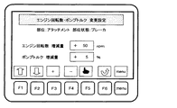
第1実施形態では、複数の部位状態の中から選択・交換可能であり、かつ、燃費に影響を与える部位として、フロント,カウンタウェイト,作動油,配管を例示したが、これらに限られない。顧客やサービスマンの判断により、部位を追加することができる。例として、部位としてアタッチメント、アタッチメント状態としてバケット(標準状態),ブレーカを追加する場合について説明する。
~ Site addition ~
In the first embodiment, the front, the counterweight, the hydraulic oil, and the piping are exemplified as the parts that can be selected and exchanged from a plurality of part states and that affect the fuel consumption, but are not limited thereto. A site can be added at the discretion of the customer or service person. As an example, a case where an attachment is added as a part and a bucket (standard state) and a breaker are added as an attachment state will be described.
図16は、部位追加時の部位選択画面であり、図17は、部位追加時のアタッチメント状態選択画面であり、図18は、部位追加時のエンジン回転数・ポンプトルク変更設定画面である。 FIG. 16 is a part selection screen when adding a part, FIG. 17 is an attachment state selection screen when adding a part, and FIG. 18 is an engine speed / pump torque change setting screen when adding a part.
サービスマンは、メニュー画面(図4参照)から、車体部位交換設定項目を選択し、モニタ装置6に部位選択画面(図6参照)を表示する。部位選択画面においてカーソルを下方向にブランク項目まで移動させると、画面下部の操作スイッチ6bのF3キーに対応する位置に、「追加」アイコンが表示される(図16参照)。サービスマンは、ブランク項目に部位項目(アタッチメント)を追加する。
The service person selects the body part replacement setting item from the menu screen (see FIG. 4), and displays the part selection screen (see FIG. 6) on the
さらに、追加部位項目(アタッチメント)を選択し、アタッチメント状態選択画面(図17参照)を表示する。アタッチメントの標準状態としてバケットを設定する。以下の動作は、部位状態追加で説明した動作と同じである。 Further, an additional part item (attachment) is selected, and an attachment state selection screen (see FIG. 17) is displayed. Set the bucket as the standard state for attachments. The following operations are the same as those described in the section state addition.
すなわち、アタッチメント状態選択画面においてカーソルを下方向にブランク項目まで移動させ、ブランク項目に部位状態項目(ブレーカ)を追加する。 That is, the cursor is moved downward to a blank item on the attachment state selection screen, and a part state item (breaker) is added to the blank item.
さらに、追加部位状態項目(ブレーカ)を選択し、エンジン回転数・ポンプトルク変更設定画面を表示する。バケットからブレーカに交換する場合は、エンジン出力が増えるように設定する必要がある。例えば、操作スイッチ6b(「+」,「−」アイコンに対応するF3キー,F4キー)を操作して、標準状態に対するエンジン回転数の増減(+50rpm)と、標準状態に対するポンプトルクの増減(+5%)を設定する(図18参照)。
Further, an additional part state item (breaker) is selected, and an engine speed / pump torque change setting screen is displayed. When exchanging from a bucket to a breaker, the engine output must be set to increase. For example, the
エンジン回転数・ポンプトルク変更設定機能部11aは、エンジン回転数・ポンプトルク変更設定テーブル14aに、選択部位(アタッチメント),選択部位状態(バケット(標準状態))に対応して、標準状態に対するエンジン回転数の増減(±0rpm)と、標準状態に対するポンプトルクの増減(±0%)を追加し、選択部位(アタッチメント),選択部位状態(ブレーカ)に対応して、標準状態に対するエンジン回転数の増減(+50rpm)と、標準状態に対するポンプトルクの増減(+5%)を追加する。
The engine speed / pump torque change setting
このように、新たな部位を追加する場合にも、部位状態や部位状態特性を反映する変更設定を容易にできる。 Thus, even when a new part is added, the change setting reflecting the part state and the part state characteristic can be easily performed.
一度、部位を追加すれば、次回以降の動作は、第1実施形態で説明した動作と同じである。 Once the site is added, the subsequent operations are the same as those described in the first embodiment.
〜削除〜
必要に応じて、部位や部位状態を削除できる。例として、追加部位(アタッチメント)を削除する場合について説明する。
~Delete~
If necessary, the part and the part state can be deleted. As an example, a case where an additional part (attachment) is deleted will be described.
図19は、部位削除時の部位選択画面である。 FIG. 19 is a part selection screen at the time of part deletion.
サービスマンは、メニュー画面(図4参照)から、車体部位交換設定項目を選択し、モニタ装置6に部位選択画面(図6参照)を表示する。カーソルを下方向に部位項目(アタッチメント)まで移動させると、画面下部の操作スイッチ6bのF3キーに対応する位置に、「削除」アイコンが表示される(図19参照)。サービスマンは、操作スイッチ6bを操作して、部位項目(アタッチメント)を削除する。
The service person selects the body part replacement setting item from the menu screen (see FIG. 4), and displays the part selection screen (see FIG. 6) on the
エンジン回転数・ポンプトルク変更設定機能部11aは、エンジン回転数・ポンプトルク変更設定テーブル14aから、選択部位(アタッチメント),選択部位状態(バケット(標準状態))に対応する、標準状態に対するエンジン回転数の増減(±0rpm)と、標準状態に対するポンプトルクの増減(±0%)を削除し、選択部位(アタッチメント),選択部位状態(ブレーカ)に対応する、標準状態に対するエンジン回転数の増減(+50rpm)と、標準状態に対するポンプトルクの増減(+5%)を削除する。
The engine speed / pump torque change setting
〜修正〜
必要に応じて、設定したエンジン回転数・ポンプトルク変更設定を修正できる。例として、設定したブレーカに対応するエンジン回転数・ポンプトルク変更設定を修正する場合について説明する。
~ Correction ~
If necessary, the set engine speed / pump torque change setting can be modified. As an example, a case where the engine speed / pump torque change setting corresponding to the set breaker is corrected will be described.
図20は、変更設定修正時のアタッチメント状態選択画面である。図21は、変更設定修正時のエンジン回転数・ポンプトルク変更設定画面である。 FIG. 20 is an attachment state selection screen at the time of change setting correction. FIG. 21 is an engine speed / pump torque change setting screen when the change setting is corrected.
サービスマンは、メニュー画面(図4参照)から、車体部位交換設定項目を選択し、モニタ装置6に部位選択画面を表示し、部位項目(アタッチメント)を選択し(図19参照)、アタッチメント状態選択画面を表示する。カーソルを下方向に部位状態項目(ブレーカ)まで移動させると、画面下部の操作スイッチ6bのF3キー,F4に対応する位置に、「削除」「修正」アイコンが表示される(図20参照)。サービスマンは、操作スイッチ6bを操作して、部位状態項目(ブレーカ)を修正するために、エンジン回転数・ポンプトルク変更設定画面(図18参照)を表示する。前回設定した標準状態に対するエンジン回転数の増減(+50rpm)と、標準状態に対するポンプトルクの増減(+5%)が表示されている。
The service person selects a body part replacement setting item from the menu screen (see FIG. 4), displays a part selection screen on the
前回設定ではブレーカによる作業性が悪い場合には、エンジン出力が更に増えるように修正する必要がある。例えば、操作スイッチ6bを操作して、標準状態に対するエンジン回転数の増減(+100rpm)と、標準状態に対するポンプトルクの増減(+10%)を設定する(図21参照)。
If the workability by the breaker is poor in the previous setting, it is necessary to correct the engine output to be further increased. For example, the
エンジン回転数・ポンプトルク変更設定機能部11aは、エンジン回転数・ポンプトルク変更設定テーブル14aの前回設定(選択部位(アタッチメント),選択部位状態(ブレーカ)に対応する、標準状態に対するエンジン回転数の増減(+50rpm)と、標準状態に対するポンプトルクの増減(+5%))から、標準状態に対するエンジン回転数の増減(+100rpm)と、標準状態に対するポンプトルクの増減(+10%)に修正する。
The engine speed / pump torque change setting
〜制限〜
第1実施形態では、複数の部位を交換した場合、エンジン回転数・ポンプトルク変更設定機能部11aは増減量を合計する。例えば、フロントを標準フロントから軽量フロントに交換し、カウンタウェイトを標準カウンタウェイトから軽量カウンタウェイトに交換し、作動油を標準作動油から省燃費作動油に交換し、配管を標準配管から拡大径配管に交換した場合、エンジン回転数・ポンプトルク変更設定機能部11aは、エンジン回転数・ポンプトルク変更設定テーブル14aから選択部位(フロント),選択部位状態(軽量フロント)に対応する、標準状態に対するエンジン回転数の増減(−50rpm)と、標準状態に対するポンプトルクの増減(−5%)を読み込み、選択部位(カウンタウェイト),選択部位状態(軽量カウンタウェイト)に対応する、標準状態に対するエンジン回転数の増減(−50rpm)と、標準状態に対するポンプトルクの増減(―5%)を読み込み、選択部位(作動油),選択部位状態(省燃費作動油)に対応する、標準状態に対するエンジン回転数の増減(−50rpm)と、標準状態に対するポンプトルクの増減(−5%)を読み込み、選択部位(配管),選択部位状態(拡大径配管)に対応する、標準状態に対するエンジン回転数の増減(−50rpm)と、標準状態に対するポンプトルクの増減(―5%)を読み込み、これらを合計し、エンジン回転数200rpm減、ポンプトルク20%減となるように変更する。
~ Restriction ~
In the first embodiment, when a plurality of parts are replaced, the engine speed / pump torque change setting
しかし、上記のようにあまりにエンジン出力を抑制すると、作業性を維持できない可能性もある。一方、部位交換により、エンジン回転数200rpm増、ポンプトルク20%増となるように変更し、エンジン出力を増すと、極端に燃費が悪化する可能性がある。 However, if the engine output is suppressed too much as described above, workability may not be maintained. On the other hand, if the engine is changed so that the engine speed is increased by 200 rpm and the pump torque is increased by 20% by exchanging the parts, and the engine output is increased, the fuel consumption may be extremely deteriorated.
これに対し、極端にエンジン回転数とポンプトルクが増減しないように、上限・下限を設けてもよい。 On the other hand, upper and lower limits may be provided so that the engine speed and pump torque do not increase or decrease extremely.
図22は、エンジン回転数とポンプトルクの増減の上限・下限を示す図である。図の見方は図12,図13と同じである。たとえば、変更の上限をエンジン回転数100rpm増、ポンプトルク10%増とし、変更の下限をエンジン回転数100rpm減、ポンプトルク10%減とする。 FIG. 22 is a diagram showing the upper and lower limits of increase / decrease in engine speed and pump torque. The way of viewing the figure is the same as in FIGS. For example, the upper limit of the change is increased by 100 rpm and the pump torque is increased by 10%, and the lower limit of change is decreased by 100 rpm and the pump torque is decreased by 10%.
例えば、増減量の合計がエンジン回転数200rpm減、ポンプトルク20%減となる場合でも、エンジン回転数・ポンプトルク変更設定機能部11aは、エンジン回転数100rpm減、ポンプトルク10%減となるように変更する。これにより、エンジン出力の極端な低減を防止し、作業性を維持できる。
For example, even when the total increase / decrease amount is 200 rpm reduction in engine speed and 20% reduction in pump torque, the engine speed / pump torque change setting
一方、例えば、増減量の合計がエンジン回転数200rpm増、ポンプトルク20%増となる場合でも、エンジン回転数・ポンプトルク変更設定機能部11aは、エンジン回転数100rpm増、ポンプトルク10%増となるように変更する。これにより、エンジン出力の極端な増加を防止し、燃費の悪化を抑制できる。
On the other hand, for example, even when the total increase / decrease amount is 200 rpm increase in the engine speed and 20% increase in the pump torque, the engine speed / pump torque change setting
1 ディーゼルエンジン
2 油圧ポンプ
3 弁装置
4 アクチュエータ
5 レギュレータ
6 モニタ装置
6a 表示画面
6b 操作スイッチ
7 配管
8 作動油
11 車体制御コントローラ
11a エンジン回転数・ポンプトルク変更設定機能部
12 エンジンコントローラ
13 モニタコントローラ
13a 部位選択画面・部位状態選択画面表示機能部
14 情報処理コントローラ
14a エンジン回転数・ポンプトルク変更設定テーブル
15 通信ライン
100 下部走行体
101 上部旋回体
102 作業フロント
103a,103b クローラ式走行装置
104a,104b 走行モータ
105 旋回モータ
106 エンジンルーム
107 キャビン
111 ブーム
112 アーム
113 バケット
114 ブームシリンダ
115 アームシリンダ
116 バケットシリンダ
1 the diesel engine 2
Claims (7)
複数の部位状態の中から1つの部位状態を選択する部位状態選択手段と、
前記部位状態選択手段により選択された部位状態に対応してエンジン回転数およびポンプトルクを変更設定するエンジン回転数・ポンプトルク変更設定手段とを備え、
前記部位状態選択手段は、複数の部位状態を同時に選択することが可能であり、
前記エンジン回転数・ポンプトルク変更設定手段は、前記部位状態選択手段により複数の部位状態が同時に選択された場合に、選択された部位状態に対応したエンジン回転数およびポンプトルクの増減量の合計値が予め設定した上限、または下限を超えないようにエンジン回転数およびポンプトルクの増減量を変更設定する
ことを特徴とする建設機械の制御システム。 It has a plurality of parts including an engine, a hydraulic pump driven by the engine, an actuator driven by hydraulic oil discharged from the hydraulic pump, and a driven member driven by the actuator, and at least 1 In a construction machine control system in which one part can be selected and exchanged from a plurality of part states,
A site state selection means for selecting one site state from a plurality of site states;
Engine speed / pump torque change setting means for changing and setting the engine speed and the pump torque corresponding to the part state selected by the part state selection means ,
The part state selection means can select a plurality of part states simultaneously,
The engine speed / pump torque change setting means, when a plurality of part states are simultaneously selected by the part state selection means, the total value of the engine speed and the increase / decrease amount of the pump torque corresponding to the selected part state construction machine control system but which is characterized in that to change setting the amount of increase or decrease the engine speed and the pump torque so as not to exceed the upper or lower limit, previously set.
前記部位状態の選択・交換可能な部位は、建設機械の燃費に影響を与える部位である
ことを特徴とする建設機械の制御システム。 The construction machine control system according to claim 1,
The part that can be selected / replaced in the part state is a part that affects the fuel consumption of the construction machine.
前記建設機械の燃費に影響を与える部位は、車体重量に影響を与える部位である
ことを特徴とする建設機械の制御システム。 In the construction machine control system according to claim 2,
The construction machine control system, wherein the part that affects the fuel consumption of the construction machine is a part that affects the weight of the vehicle body.
前記建設機械の燃費に影響を与える部位は、作動油の流体抵抗に影響を与える部位である
ことを特徴とする建設機械の制御システム。 In the construction machine control system according to claim 2,
The construction machine control system, wherein the part that affects the fuel consumption of the construction machine is a part that affects the fluid resistance of the hydraulic oil.
前記作動油の流体抵抗に影響を与える部位は作動油である
ことを特徴とする建設機械の制御システム。 In the construction machine control system according to claim 4,
A construction machine control system characterized in that a part that affects the fluid resistance of the hydraulic oil is hydraulic oil.
前記作動油の流体抵抗に影響を与える部位は作動油配管である
ことを特徴とする建設機械の制御システム。 In the construction machine control system according to claim 4,
The part that affects the fluid resistance of the hydraulic oil is a hydraulic oil pipe.
前記部位状態選択手段は、モニタ装置の表示画面を有する
ことを特徴とする建設機械の制御システム。 The construction machine control system according to claim 1,
The part state selection means has a display screen of a monitor device.
Priority Applications (6)
| Application Number | Priority Date | Filing Date | Title |
|---|---|---|---|
| JP2011106572A JP5566333B2 (en) | 2011-05-11 | 2011-05-11 | Construction machine control system |
| KR1020137029440A KR101911572B1 (en) | 2011-05-11 | 2012-04-05 | System for controlling construction machine |
| CN201280022501.9A CN103534421B (en) | 2011-05-11 | 2012-04-05 | The control system of engineering machinery |
| EP12782784.8A EP2708662B1 (en) | 2011-05-11 | 2012-04-05 | System for controlling construction machine |
| US14/111,192 US9260838B2 (en) | 2011-05-11 | 2012-04-05 | Control system for construction machine |
| PCT/JP2012/059405 WO2012153586A1 (en) | 2011-05-11 | 2012-04-05 | System for controlling construction machine |
Applications Claiming Priority (1)
| Application Number | Priority Date | Filing Date | Title |
|---|---|---|---|
| JP2011106572A JP5566333B2 (en) | 2011-05-11 | 2011-05-11 | Construction machine control system |
Publications (3)
| Publication Number | Publication Date |
|---|---|
| JP2012237131A JP2012237131A (en) | 2012-12-06 |
| JP2012237131A5 JP2012237131A5 (en) | 2013-06-27 |
| JP5566333B2 true JP5566333B2 (en) | 2014-08-06 |
Family
ID=47139072
Family Applications (1)
| Application Number | Title | Priority Date | Filing Date |
|---|---|---|---|
| JP2011106572A Expired - Fee Related JP5566333B2 (en) | 2011-05-11 | 2011-05-11 | Construction machine control system |
Country Status (6)
| Country | Link |
|---|---|
| US (1) | US9260838B2 (en) |
| EP (1) | EP2708662B1 (en) |
| JP (1) | JP5566333B2 (en) |
| KR (1) | KR101911572B1 (en) |
| CN (1) | CN103534421B (en) |
| WO (1) | WO2012153586A1 (en) |
Families Citing this family (10)
| Publication number | Priority date | Publication date | Assignee | Title |
|---|---|---|---|---|
| KR102015141B1 (en) * | 2013-03-29 | 2019-08-27 | 두산인프라코어 주식회사 | Control system and method of Hydraulic Pump for Construction Machinery |
| JP5583872B1 (en) * | 2013-12-06 | 2014-09-03 | 株式会社小松製作所 | Excavator |
| WO2015111777A1 (en) * | 2014-01-27 | 2015-07-30 | 볼보 컨스트럭션 이큅먼트 에이비 | Outrigger and dozer control using gui |
| US10208455B2 (en) * | 2016-03-17 | 2019-02-19 | Deere & Company | In-vehicle dynometer |
| JP6580618B2 (en) * | 2017-03-21 | 2019-09-25 | 日立建機株式会社 | Construction machinery |
| JP2019078132A (en) * | 2017-10-27 | 2019-05-23 | コベルコ建機株式会社 | Work machine |
| DE102018208500B4 (en) * | 2018-05-29 | 2022-11-17 | Moba Mobile Automation Ag | Operating device for a construction machine |
| EP3827139A1 (en) * | 2018-07-25 | 2021-06-02 | Clark Equipment Company | Hydraulic oil temperature management for a power machine |
| CA3119273A1 (en) | 2018-11-09 | 2020-05-14 | Iocurrents, Inc. | Machine learning-based prediction, planning, and optimization of trip time, trip cost, and/or pollutant emission during navigation |
| KR20210103782A (en) * | 2020-02-14 | 2021-08-24 | 두산인프라코어 주식회사 | Control method for construction machinery and contorl system for construction machinery |
Family Cites Families (57)
| Publication number | Priority date | Publication date | Assignee | Title |
|---|---|---|---|---|
| JPH0657787A (en) * | 1992-08-06 | 1994-03-01 | Yutani Heavy Ind Ltd | Flow rate control device for crusher |
| US5850341A (en) * | 1994-06-30 | 1998-12-15 | Caterpillar Inc. | Method and apparatus for monitoring material removal using mobile machinery |
| JP3589710B2 (en) | 1994-09-28 | 2004-11-17 | 住友建機製造株式会社 | Engine and pump control devices for construction machinery |
| JP3609182B2 (en) * | 1996-01-08 | 2005-01-12 | 日立建機株式会社 | Hydraulic drive unit for construction machinery |
| JPH10237904A (en) | 1997-02-25 | 1998-09-08 | Shin Caterpillar Mitsubishi Ltd | Method of controlling construction machinery and device thereof |
| JP3323791B2 (en) * | 1997-11-25 | 2002-09-09 | 新キャタピラー三菱株式会社 | Control device and control method for construction machine |
| US6923285B1 (en) * | 2000-02-01 | 2005-08-02 | Clark Equipment Company | Attachment control device |
| EP1273720B1 (en) | 2000-03-31 | 2014-09-24 | Hitachi Construction Machinery Co., Ltd. | System for changing function of work machine and base station |
| JP4098955B2 (en) * | 2000-12-18 | 2008-06-11 | 日立建機株式会社 | Construction machine control equipment |
| US7048515B2 (en) * | 2001-06-21 | 2006-05-23 | Hitachi Construction Machinery Co., Ltd. | Hydraulic drive system and method using a fuel injection control unit |
| AU2003271499A1 (en) * | 2002-10-29 | 2004-05-25 | Photonfocus Ag | Optoelectronic sensor |
| JP2004150304A (en) * | 2002-10-29 | 2004-05-27 | Komatsu Ltd | Controller of engine |
| JP2004188326A (en) * | 2002-12-11 | 2004-07-08 | Hitachi Constr Mach Co Ltd | Self-traveling type crusher |
| US6925375B2 (en) * | 2003-03-20 | 2005-08-02 | Detroit Diesel Corporation | System and method for determining a parameter set for an engine controller module |
| CN100436786C (en) * | 2003-05-07 | 2008-11-26 | 株式会社小松制作所 | Working machine having prime mover control device |
| JP4484467B2 (en) * | 2003-08-01 | 2010-06-16 | 日立建機株式会社 | Traveling hydraulic working machine |
| GB2421808B8 (en) * | 2003-08-11 | 2007-06-18 | Komatsu Mfg Co Ltd | Hydraulic operation controlling unit and hydraulicexcavator provided with same |
| JP4173162B2 (en) * | 2003-12-09 | 2008-10-29 | 株式会社小松製作所 | Apparatus and method for hydraulic drive control of construction machine |
| WO2005098148A1 (en) * | 2004-04-08 | 2005-10-20 | Komatsu Ltd. | Hydraulic drive device for working machine |
| KR20070007174A (en) * | 2004-05-07 | 2007-01-12 | 가부시키가이샤 고마쓰 세이사쿠쇼 | Hydraulic drive apparatus of work machine |
| JP4270505B2 (en) * | 2004-08-11 | 2009-06-03 | 株式会社小松製作所 | Load control device for engine of work vehicle |
| US7400959B2 (en) * | 2004-08-27 | 2008-07-15 | Caterpillar Inc. | System for customizing responsiveness of a work machine |
| WO2006035589A1 (en) * | 2004-09-27 | 2006-04-06 | Hitachi Construction Machinery Co., Ltd. | Engine control device for working vehicle |
| JP4188902B2 (en) * | 2004-11-22 | 2008-12-03 | 日立建機株式会社 | Control equipment for hydraulic construction machinery |
| JP4315248B2 (en) * | 2004-12-13 | 2009-08-19 | 日立建機株式会社 | Control device for traveling work vehicle |
| GB0507928D0 (en) * | 2005-04-20 | 2005-05-25 | Cnh Belgium Nv | Input device for agricultural vehicle information display |
| GB0507931D0 (en) * | 2005-04-20 | 2005-06-01 | Cnh Belgium Nv | Agricultural vehicle performance maps |
| GB0507930D0 (en) * | 2005-04-20 | 2005-06-01 | Cnh Belgium Nv | Settings control of an agricultural vehicle |
| JP4785522B2 (en) * | 2005-12-22 | 2011-10-05 | 株式会社小松製作所 | Engine control device for work vehicle |
| US7343897B2 (en) * | 2006-03-22 | 2008-03-18 | Gm Global Technology Operations, Inc. | Engine control system with user-commanded engine speed adjustments in varying increments |
| US7894963B2 (en) * | 2006-12-21 | 2011-02-22 | Caterpillar Inc. | System and method for controlling a machine |
| US8640451B2 (en) * | 2007-01-18 | 2014-02-04 | Komatsu Ltd. | Engine control device, and its control method |
| EP2144780B1 (en) * | 2007-04-10 | 2015-08-19 | Volvo Construction Equipment AB | A method and a system for providing feedback to a vehicle operator |
| JP5064160B2 (en) * | 2007-09-19 | 2012-10-31 | 株式会社小松製作所 | Engine control device |
| CN101835968B (en) * | 2007-10-24 | 2013-07-24 | 日立建机株式会社 | Engine control device for working vehicle |
| US7738979B2 (en) * | 2007-11-01 | 2010-06-15 | Caterpillar Inc. | Work tool notification and user-selectable machine control configuration |
| JP5121405B2 (en) * | 2007-11-13 | 2013-01-16 | 株式会社小松製作所 | Engine control device for construction machinery |
| CN102966446B (en) * | 2008-02-18 | 2015-09-16 | 株式会社小松制作所 | The control gear of motor and controlling method thereof |
| US8392075B2 (en) * | 2008-02-25 | 2013-03-05 | Clark Equipment Company | Carrier and backhoe control system and method |
| WO2009116250A1 (en) * | 2008-03-21 | 2009-09-24 | 株式会社小松製作所 | Engine-driven machine, control device for engine-driven machine, and method of controlling maximum output characteristics of engine |
| JP5219262B2 (en) * | 2008-07-16 | 2013-06-26 | ヤンマー株式会社 | Tractor |
| JP4774096B2 (en) * | 2008-11-17 | 2011-09-14 | 日立建機株式会社 | Exhaust gas purification system for work machines |
| US9371754B2 (en) * | 2009-03-12 | 2016-06-21 | Caterpillar Inc. | Diesel particulate filter regeneration control and method |
| JP5164933B2 (en) * | 2009-06-19 | 2013-03-21 | 日立建機株式会社 | Control device for work vehicle |
| WO2010147211A1 (en) * | 2009-06-19 | 2010-12-23 | 日立建機株式会社 | Industrial vehicle control device |
| CN102803685B (en) * | 2009-06-19 | 2015-09-02 | 日立建机株式会社 | The prime mover control device of working truck |
| KR101378653B1 (en) * | 2009-12-18 | 2014-03-26 | 가부시키가이샤 고마쓰 세이사쿠쇼 | Work vehicle monitoring device |
| KR20120123277A (en) * | 2010-01-18 | 2012-11-08 | 히다찌 겐끼 가부시키가이샤 | Drive control device for working vehicle |
| US8701401B2 (en) * | 2010-02-03 | 2014-04-22 | Komatsu Ltd. | Engine control device |
| WO2011096383A1 (en) * | 2010-02-03 | 2011-08-11 | 株式会社小松製作所 | Engine control device |
| US8768577B2 (en) * | 2010-05-04 | 2014-07-01 | Clark Equipment Company | Implement interface display |
| JP5226734B2 (en) * | 2010-05-20 | 2013-07-03 | 株式会社小松製作所 | Hybrid construction machinery |
| US9353769B2 (en) * | 2010-07-28 | 2016-05-31 | Illinois Tool Works Inc. | Hydraulic tool that commands prime mover output |
| JP5350348B2 (en) * | 2010-09-30 | 2013-11-27 | 株式会社小松製作所 | Guidance output device and guidance output method |
| JP4948643B1 (en) * | 2010-12-24 | 2012-06-06 | 株式会社小松製作所 | Guidance output device, guidance output method, and construction machine equipped with guidance output device |
| US8401751B2 (en) * | 2011-03-01 | 2013-03-19 | Caterpillar Inc. | Shift control and method |
| US8914215B2 (en) * | 2012-11-30 | 2014-12-16 | Caterpillar Inc. | Measuring and displaying tractor performance |
-
2011
- 2011-05-11 JP JP2011106572A patent/JP5566333B2/en not_active Expired - Fee Related
-
2012
- 2012-04-05 CN CN201280022501.9A patent/CN103534421B/en not_active Expired - Fee Related
- 2012-04-05 EP EP12782784.8A patent/EP2708662B1/en not_active Not-in-force
- 2012-04-05 WO PCT/JP2012/059405 patent/WO2012153586A1/en active Application Filing
- 2012-04-05 KR KR1020137029440A patent/KR101911572B1/en active IP Right Grant
- 2012-04-05 US US14/111,192 patent/US9260838B2/en not_active Expired - Fee Related
Also Published As
| Publication number | Publication date |
|---|---|
| KR101911572B1 (en) | 2018-10-24 |
| EP2708662A1 (en) | 2014-03-19 |
| WO2012153586A1 (en) | 2012-11-15 |
| CN103534421B (en) | 2016-06-15 |
| KR20140048114A (en) | 2014-04-23 |
| US20140039768A1 (en) | 2014-02-06 |
| EP2708662A4 (en) | 2015-04-15 |
| EP2708662B1 (en) | 2017-04-05 |
| US9260838B2 (en) | 2016-02-16 |
| JP2012237131A (en) | 2012-12-06 |
| CN103534421A (en) | 2014-01-22 |
Similar Documents
| Publication | Publication Date | Title |
|---|---|---|
| JP5566333B2 (en) | Construction machine control system | |
| JP6776343B2 (en) | Excavator display | |
| JP5226734B2 (en) | Hybrid construction machinery | |
| JP6808377B2 (en) | Excavator display | |
| WO2012141110A1 (en) | Display device of working machine | |
| JP5391101B2 (en) | Engine control device | |
| JPWO2016047167A1 (en) | Work machine display | |
| JP6682476B2 (en) | Work machine | |
| JP6862266B2 (en) | Work machine | |
| JP6980643B2 (en) | Display control devices, work machines, programs, and their recording media | |
| JP6559529B2 (en) | Construction machinery | |
| JP6683664B2 (en) | Wheel loader | |
| JP6873809B2 (en) | Work machine | |
| JP2003083113A (en) | Method and device for confirming engine performance of working machine, and pump control device | |
| JP2020104810A (en) | Display control device, work machine, program, and recording medium for the program | |
| JP2020169708A (en) | Operation control device for work vehicle | |
| JP2020104811A (en) | Display control device, work machine, program, and recording medium for the program | |
| JP7285356B1 (en) | Working machine diagnostic device | |
| JP7051674B2 (en) | Display control devices, work machines, programs, and their recording media | |
| JP7051675B2 (en) | Display control devices, work machines, programs, and their recording media | |
| JP2004169589A (en) | Engine control system of working machine | |
| JP6872510B2 (en) | Work machine | |
| JP7039505B2 (en) | Construction machinery | |
| JP5254262B2 (en) | Hydraulic work machine display | |
| KR20240002909A (en) | Display control device for construction machine |
Legal Events
| Date | Code | Title | Description |
|---|---|---|---|
| A521 | Request for written amendment filed |
Free format text: JAPANESE INTERMEDIATE CODE: A523 Effective date: 20130514 |
|
| A621 | Written request for application examination |
Free format text: JAPANESE INTERMEDIATE CODE: A621 Effective date: 20130514 |
|
| A131 | Notification of reasons for refusal |
Free format text: JAPANESE INTERMEDIATE CODE: A131 Effective date: 20140128 |
|
| A521 | Request for written amendment filed |
Free format text: JAPANESE INTERMEDIATE CODE: A523 Effective date: 20140331 |
|
| RD02 | Notification of acceptance of power of attorney |
Free format text: JAPANESE INTERMEDIATE CODE: A7422 Effective date: 20140331 |
|
| TRDD | Decision of grant or rejection written | ||
| A01 | Written decision to grant a patent or to grant a registration (utility model) |
Free format text: JAPANESE INTERMEDIATE CODE: A01 Effective date: 20140617 |
|
| A61 | First payment of annual fees (during grant procedure) |
Free format text: JAPANESE INTERMEDIATE CODE: A61 Effective date: 20140617 |
|
| R150 | Certificate of patent or registration of utility model |
Ref document number: 5566333 Country of ref document: JP Free format text: JAPANESE INTERMEDIATE CODE: R150 |
|
| LAPS | Cancellation because of no payment of annual fees |