JP5563349B2 - Method for producing transfer body - Google Patents
Method for producing transfer body Download PDFInfo
- Publication number
- JP5563349B2 JP5563349B2 JP2010079859A JP2010079859A JP5563349B2 JP 5563349 B2 JP5563349 B2 JP 5563349B2 JP 2010079859 A JP2010079859 A JP 2010079859A JP 2010079859 A JP2010079859 A JP 2010079859A JP 5563349 B2 JP5563349 B2 JP 5563349B2
- Authority
- JP
- Japan
- Prior art keywords
- roller
- film
- transfer
- transfer film
- release
- Prior art date
- Legal status (The legal status is an assumption and is not a legal conclusion. Google has not performed a legal analysis and makes no representation as to the accuracy of the status listed.)
- Active
Links
- 238000004519 manufacturing process Methods 0.000 title claims description 30
- 239000000758 substrate Substances 0.000 claims description 74
- 238000000034 method Methods 0.000 claims description 22
- 239000011521 glass Substances 0.000 claims description 19
- 238000010304 firing Methods 0.000 claims description 18
- 239000012790 adhesive layer Substances 0.000 claims description 16
- 230000007246 mechanism Effects 0.000 claims description 12
- 239000000843 powder Substances 0.000 claims description 11
- 238000004804 winding Methods 0.000 claims description 10
- 238000003825 pressing Methods 0.000 claims description 7
- 239000011368 organic material Substances 0.000 claims description 4
- 238000005304 joining Methods 0.000 claims description 3
- 238000013518 transcription Methods 0.000 claims 1
- 230000035897 transcription Effects 0.000 claims 1
- 239000010410 layer Substances 0.000 description 15
- 239000000126 substance Substances 0.000 description 9
- 239000000463 material Substances 0.000 description 8
- 238000000576 coating method Methods 0.000 description 7
- 230000008569 process Effects 0.000 description 7
- 230000032798 delamination Effects 0.000 description 6
- 239000002904 solvent Substances 0.000 description 6
- 238000007796 conventional method Methods 0.000 description 5
- 238000007639 printing Methods 0.000 description 5
- 239000011248 coating agent Substances 0.000 description 4
- NIXOWILDQLNWCW-UHFFFAOYSA-N acrylic acid group Chemical group C(C=C)(=O)O NIXOWILDQLNWCW-UHFFFAOYSA-N 0.000 description 3
- 239000000853 adhesive Substances 0.000 description 3
- 230000001070 adhesive effect Effects 0.000 description 3
- -1 polyethylene Polymers 0.000 description 3
- RTZKZFJDLAIYFH-UHFFFAOYSA-N Diethyl ether Chemical compound CCOCC RTZKZFJDLAIYFH-UHFFFAOYSA-N 0.000 description 2
- 239000004820 Pressure-sensitive adhesive Substances 0.000 description 2
- VYPSYNLAJGMNEJ-UHFFFAOYSA-N Silicium dioxide Chemical compound O=[Si]=O VYPSYNLAJGMNEJ-UHFFFAOYSA-N 0.000 description 2
- GWEVSGVZZGPLCZ-UHFFFAOYSA-N Titan oxide Chemical compound O=[Ti]=O GWEVSGVZZGPLCZ-UHFFFAOYSA-N 0.000 description 2
- 230000007547 defect Effects 0.000 description 2
- 239000007788 liquid Substances 0.000 description 2
- 239000008204 material by function Substances 0.000 description 2
- 230000035699 permeability Effects 0.000 description 2
- 239000004014 plasticizer Substances 0.000 description 2
- 239000011241 protective layer Substances 0.000 description 2
- LNAZSHAWQACDHT-XIYTZBAFSA-N (2r,3r,4s,5r,6s)-4,5-dimethoxy-2-(methoxymethyl)-3-[(2s,3r,4s,5r,6r)-3,4,5-trimethoxy-6-(methoxymethyl)oxan-2-yl]oxy-6-[(2r,3r,4s,5r,6r)-4,5,6-trimethoxy-2-(methoxymethyl)oxan-3-yl]oxyoxane Chemical compound CO[C@@H]1[C@@H](OC)[C@H](OC)[C@@H](COC)O[C@H]1O[C@H]1[C@H](OC)[C@@H](OC)[C@H](O[C@H]2[C@@H]([C@@H](OC)[C@H](OC)O[C@@H]2COC)OC)O[C@@H]1COC LNAZSHAWQACDHT-XIYTZBAFSA-N 0.000 description 1
- 229920002799 BoPET Polymers 0.000 description 1
- 239000004215 Carbon black (E152) Substances 0.000 description 1
- LFQSCWFLJHTTHZ-UHFFFAOYSA-N Ethanol Chemical compound CCO LFQSCWFLJHTTHZ-UHFFFAOYSA-N 0.000 description 1
- ZZSNKZQZMQGXPY-UHFFFAOYSA-N Ethyl cellulose Chemical compound CCOCC1OC(OC)C(OCC)C(OCC)C1OC1C(O)C(O)C(OC)C(CO)O1 ZZSNKZQZMQGXPY-UHFFFAOYSA-N 0.000 description 1
- 239000001856 Ethyl cellulose Substances 0.000 description 1
- 239000000020 Nitrocellulose Substances 0.000 description 1
- 238000006124 Pilkington process Methods 0.000 description 1
- 229920003171 Poly (ethylene oxide) Polymers 0.000 description 1
- 239000004698 Polyethylene Substances 0.000 description 1
- 239000004642 Polyimide Substances 0.000 description 1
- 239000004372 Polyvinyl alcohol Substances 0.000 description 1
- 229910019899 RuO Inorganic materials 0.000 description 1
- XTXRWKRVRITETP-UHFFFAOYSA-N Vinyl acetate Chemical compound CC(=O)OC=C XTXRWKRVRITETP-UHFFFAOYSA-N 0.000 description 1
- FJWGYAHXMCUOOM-QHOUIDNNSA-N [(2s,3r,4s,5r,6r)-2-[(2r,3r,4s,5r,6s)-4,5-dinitrooxy-2-(nitrooxymethyl)-6-[(2r,3r,4s,5r,6s)-4,5,6-trinitrooxy-2-(nitrooxymethyl)oxan-3-yl]oxyoxan-3-yl]oxy-3,5-dinitrooxy-6-(nitrooxymethyl)oxan-4-yl] nitrate Chemical compound O([C@@H]1O[C@@H]([C@H]([C@H](O[N+]([O-])=O)[C@H]1O[N+]([O-])=O)O[C@H]1[C@@H]([C@@H](O[N+]([O-])=O)[C@H](O[N+]([O-])=O)[C@@H](CO[N+]([O-])=O)O1)O[N+]([O-])=O)CO[N+](=O)[O-])[C@@H]1[C@@H](CO[N+]([O-])=O)O[C@@H](O[N+]([O-])=O)[C@H](O[N+]([O-])=O)[C@H]1O[N+]([O-])=O FJWGYAHXMCUOOM-QHOUIDNNSA-N 0.000 description 1
- DHKHKXVYLBGOIT-UHFFFAOYSA-N acetaldehyde Diethyl Acetal Natural products CCOC(C)OCC DHKHKXVYLBGOIT-UHFFFAOYSA-N 0.000 description 1
- 150000001241 acetals Chemical class 0.000 description 1
- 239000003522 acrylic cement Substances 0.000 description 1
- 229920000180 alkyd Polymers 0.000 description 1
- 239000000956 alloy Substances 0.000 description 1
- 229910045601 alloy Inorganic materials 0.000 description 1
- 230000004888 barrier function Effects 0.000 description 1
- 230000008901 benefit Effects 0.000 description 1
- 229910052797 bismuth Inorganic materials 0.000 description 1
- 238000009835 boiling Methods 0.000 description 1
- 239000003990 capacitor Substances 0.000 description 1
- 229910052681 coesite Inorganic materials 0.000 description 1
- 230000000052 comparative effect Effects 0.000 description 1
- 238000010276 construction Methods 0.000 description 1
- 229910052802 copper Inorganic materials 0.000 description 1
- 229910052906 cristobalite Inorganic materials 0.000 description 1
- 239000003989 dielectric material Substances 0.000 description 1
- 235000014113 dietary fatty acids Nutrition 0.000 description 1
- 230000000694 effects Effects 0.000 description 1
- 150000002148 esters Chemical class 0.000 description 1
- 229920001249 ethyl cellulose Polymers 0.000 description 1
- 235000019325 ethyl cellulose Nutrition 0.000 description 1
- 239000000194 fatty acid Substances 0.000 description 1
- 229930195729 fatty acid Natural products 0.000 description 1
- 229910052737 gold Inorganic materials 0.000 description 1
- 238000007756 gravure coating Methods 0.000 description 1
- 229930195733 hydrocarbon Natural products 0.000 description 1
- 150000002430 hydrocarbons Chemical class 0.000 description 1
- 229910052738 indium Inorganic materials 0.000 description 1
- 150000002576 ketones Chemical class 0.000 description 1
- 238000010030 laminating Methods 0.000 description 1
- 229910052745 lead Inorganic materials 0.000 description 1
- 229920000609 methyl cellulose Polymers 0.000 description 1
- 239000001923 methylcellulose Substances 0.000 description 1
- 239000000203 mixture Substances 0.000 description 1
- 229910003465 moissanite Inorganic materials 0.000 description 1
- 229910052759 nickel Inorganic materials 0.000 description 1
- 229920001220 nitrocellulos Polymers 0.000 description 1
- 238000007645 offset printing Methods 0.000 description 1
- 239000005416 organic matter Substances 0.000 description 1
- 150000003014 phosphoric acid esters Chemical class 0.000 description 1
- 229920003023 plastic Polymers 0.000 description 1
- 239000004033 plastic Substances 0.000 description 1
- 229920002037 poly(vinyl butyral) polymer Polymers 0.000 description 1
- 229920000728 polyester Polymers 0.000 description 1
- 229920000573 polyethylene Polymers 0.000 description 1
- 229920000139 polyethylene terephthalate Polymers 0.000 description 1
- 239000005020 polyethylene terephthalate Substances 0.000 description 1
- 229920001721 polyimide Polymers 0.000 description 1
- 229920001296 polysiloxane Polymers 0.000 description 1
- 229920002451 polyvinyl alcohol Polymers 0.000 description 1
- 238000000197 pyrolysis Methods 0.000 description 1
- 229920005989 resin Polymers 0.000 description 1
- 239000011347 resin Substances 0.000 description 1
- 238000007650 screen-printing Methods 0.000 description 1
- HBMJWWWQQXIZIP-UHFFFAOYSA-N silicon carbide Chemical compound [Si+]#[C-] HBMJWWWQQXIZIP-UHFFFAOYSA-N 0.000 description 1
- 229910010271 silicon carbide Inorganic materials 0.000 description 1
- 239000000377 silicon dioxide Substances 0.000 description 1
- 235000012239 silicon dioxide Nutrition 0.000 description 1
- 229920002050 silicone resin Polymers 0.000 description 1
- 229910052709 silver Inorganic materials 0.000 description 1
- 239000007787 solid Substances 0.000 description 1
- 229910052682 stishovite Inorganic materials 0.000 description 1
- 238000005979 thermal decomposition reaction Methods 0.000 description 1
- 229910052718 tin Inorganic materials 0.000 description 1
- 229910052905 tridymite Inorganic materials 0.000 description 1
- 229920002554 vinyl polymer Polymers 0.000 description 1
- XLYOFNOQVPJJNP-UHFFFAOYSA-N water Substances O XLYOFNOQVPJJNP-UHFFFAOYSA-N 0.000 description 1
- 229910052725 zinc Inorganic materials 0.000 description 1
Images


Classifications
-
- B—PERFORMING OPERATIONS; TRANSPORTING
- B32—LAYERED PRODUCTS
- B32B—LAYERED PRODUCTS, i.e. PRODUCTS BUILT-UP OF STRATA OF FLAT OR NON-FLAT, e.g. CELLULAR OR HONEYCOMB, FORM
- B32B37/00—Methods or apparatus for laminating, e.g. by curing or by ultrasonic bonding
- B32B37/02—Methods or apparatus for laminating, e.g. by curing or by ultrasonic bonding characterised by a sequence of laminating steps, e.g. by adding new layers at consecutive laminating stations
- B32B37/025—Transfer laminating
-
- B—PERFORMING OPERATIONS; TRANSPORTING
- B29—WORKING OF PLASTICS; WORKING OF SUBSTANCES IN A PLASTIC STATE IN GENERAL
- B29C—SHAPING OR JOINING OF PLASTICS; SHAPING OF MATERIAL IN A PLASTIC STATE, NOT OTHERWISE PROVIDED FOR; AFTER-TREATMENT OF THE SHAPED PRODUCTS, e.g. REPAIRING
- B29C43/00—Compression moulding, i.e. applying external pressure to flow the moulding material; Apparatus therefor
- B29C43/02—Compression moulding, i.e. applying external pressure to flow the moulding material; Apparatus therefor of articles of definite length, i.e. discrete articles
- B29C43/18—Compression moulding, i.e. applying external pressure to flow the moulding material; Apparatus therefor of articles of definite length, i.e. discrete articles incorporating preformed parts or layers, e.g. compression moulding around inserts or for coating articles
-
- B—PERFORMING OPERATIONS; TRANSPORTING
- B29—WORKING OF PLASTICS; WORKING OF SUBSTANCES IN A PLASTIC STATE IN GENERAL
- B29C—SHAPING OR JOINING OF PLASTICS; SHAPING OF MATERIAL IN A PLASTIC STATE, NOT OTHERWISE PROVIDED FOR; AFTER-TREATMENT OF THE SHAPED PRODUCTS, e.g. REPAIRING
- B29C43/00—Compression moulding, i.e. applying external pressure to flow the moulding material; Apparatus therefor
- B29C43/22—Compression moulding, i.e. applying external pressure to flow the moulding material; Apparatus therefor of articles of indefinite length
- B29C43/30—Making multilayered or multicoloured articles
-
- B—PERFORMING OPERATIONS; TRANSPORTING
- B29—WORKING OF PLASTICS; WORKING OF SUBSTANCES IN A PLASTIC STATE IN GENERAL
- B29C—SHAPING OR JOINING OF PLASTICS; SHAPING OF MATERIAL IN A PLASTIC STATE, NOT OTHERWISE PROVIDED FOR; AFTER-TREATMENT OF THE SHAPED PRODUCTS, e.g. REPAIRING
- B29C43/00—Compression moulding, i.e. applying external pressure to flow the moulding material; Apparatus therefor
- B29C43/32—Component parts, details or accessories; Auxiliary operations
- B29C43/36—Moulds for making articles of definite length, i.e. discrete articles
- B29C43/3697—Moulds for making articles of definite length, i.e. discrete articles comprising rollers or belts cooperating with non-rotating mould parts
-
- B—PERFORMING OPERATIONS; TRANSPORTING
- B32—LAYERED PRODUCTS
- B32B—LAYERED PRODUCTS, i.e. PRODUCTS BUILT-UP OF STRATA OF FLAT OR NON-FLAT, e.g. CELLULAR OR HONEYCOMB, FORM
- B32B2309/00—Parameters for the laminating or treatment process; Apparatus details
- B32B2309/12—Pressure
Landscapes
- Decoration By Transfer Pictures (AREA)
- Manufacturing Of Printed Wiring (AREA)
- Laminated Bodies (AREA)
- Adhesive Tape Dispensing Devices (AREA)
Description
本発明は、転写体の製造方法に関する。詳しくは、ガラスなどの表面が平滑で、通気性のない基体に、剥離フィルムと転写膜を有する転写フィルムを貼付し、剥離フィルムを剥離する転写体の製造方法に関する。 The present invention relates to a method for producing a transfer body. Specifically, the present invention relates to a method for producing a transfer body in which a transfer film having a release film and a transfer film is attached to a substrate having a smooth surface such as glass and having no air permeability, and the release film is released.
ガラス等の基体に配線回路や電極等の導電性パターンや模様等の装飾パターンを形成するために、転写フィルムが用いられる場合がある。このような転写フィルムを用いる方法は、基体の寸法や形状にかかわらず、上記導電性パターンや装飾パターンなどを基体に追従させることが可能であり、パターニング性や生産性に優れ、低コストで、任意の基体に形成することができるという利点がある。このような転写方式に適応する種々の転写フィルムが提案されている(例えば特許文献1など)。 A transfer film may be used to form a decorative pattern such as a conductive pattern or pattern such as a wiring circuit or an electrode on a substrate such as glass. The method using such a transfer film is capable of following the conductive pattern, decorative pattern, and the like regardless of the size and shape of the substrate, and is excellent in patternability and productivity, at low cost, There is an advantage that it can be formed on any substrate. Various transfer films suitable for such a transfer method have been proposed (for example, Patent Document 1).
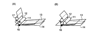
従来、基体上に効率的に転写フィルムを貼付する方法として、図1に示されるような方法が用いられている。すなわち、貼付ローラー11及び剥離ローラー12を取り付けているヘッドを下降させて、貼付ローラー及び剥離ローラーで転写フィルム13を基体14に押し付ける工程(図1(A))、貼付ローラー11を、転写フィルムを供給する供給ローラー(図示せず)側へ移動して転写フィルムを貼付する工程(図1(B))、剥離ローラーを供給ローラー側へ移動して剥離フィルムを基体から剥離する工程(図1(C))、次いでヘッドを上昇させて、貼付ローラー11及び剥離ローラー12を基体14から離間させ(図1(D))、元の位置に戻す工程を有する方法である。
転写に際しては、転写用素材を転写フィルム側に残留させずに期体上に転写させることが重要であり、種々の転写装置が提案されている(例えば、特許文献2参照)。
Conventionally, a method as shown in FIG. 1 has been used as a method for efficiently attaching a transfer film on a substrate. That is, the process of lowering the head to which the
At the time of transfer, it is important to transfer the transfer material onto the stage without remaining on the transfer film side, and various transfer devices have been proposed (for example, see Patent Document 2).
上記したような従来の転写フィルムの貼付方法では、転写フィルムを基体に貼付するに際し、転写フィルムと基体の間や転写フィルムの層間に空気が噛み込む場合がある。この場合に、剥離ローラーの移動に伴って、該空気も移動し、転写フィルムと基体の界面の接着不良を生じさせ、部分的に密着力が得られない部分が生じたり、転写フィルムの層間剥離を引き起こす場合があった。このような、転写フィルムの層間剥離の問題は、特に転写膜に無機粉体と焼成除去可能な有機物を含有する焼成用転写フィルムに顕著に生じる。
また、転写フィルムから剥離フィルムを剥離させる際に、転写膜を構成する機能性パターンが破壊される場合があった。
さらに、転写フィルムの転写が終了し、貼付ローラー及び剥離ローラーを取り付けているヘッドを基体から離間させる際に、基体に必要以上の力がかかり、基体に割れが生じる場合があり、また転写フィルムにたるみを生じさせ、連続的に次の転写を行う際に不都合を生じる場合があった。
そこで、本発明は、転写フィルムと基体の界面の接着不良がなく、また転写フィルムの層間剥離を生じさせない転写体の製造方法、さらには、転写フィルムから剥離フィルムを剥離させる際に、転写膜を構成する機能性パターンが破壊されることがなく、また、貼付ローラー及び剥離ローラーを基体から離間させる際に、基体に損傷を与えることがない、生産性の高い転写体の製造方法を提供することを目的とする。
In the conventional transfer film attaching method as described above, when the transfer film is attached to the substrate, air may be caught between the transfer film and the substrate or between the layers of the transfer film. In this case, the air also moves with the movement of the peeling roller, causing poor adhesion at the interface between the transfer film and the substrate, resulting in a part where the adhesion force cannot be obtained partially, or delamination of the transfer film Could cause. Such a problem of delamination of the transfer film is particularly noticeable in a transfer film for baking in which the transfer film contains inorganic powder and an organic substance that can be removed by baking.
Moreover, when peeling a peeling film from a transfer film, the functional pattern which comprises a transfer film may be destroyed.
Furthermore, when the transfer of the transfer film is completed and the head to which the application roller and the release roller are attached is separated from the substrate, an excessive force is applied to the substrate, and the substrate may be cracked. In some cases, slack is generated, and inconvenience is caused when the next transfer is continuously performed.
Therefore, the present invention provides a method for producing a transfer body that does not cause poor adhesion at the interface between the transfer film and the substrate and does not cause delamination of the transfer film, and further, when the release film is peeled from the transfer film, Provided is a method for producing a transfer body with high productivity, in which a functional pattern to be formed is not destroyed, and when a sticking roller and a peeling roller are separated from a substrate, the substrate is not damaged. With the goal.
本発明者らは、上記課題に対して、貼付ローラー及び剥離ローラーと、基体及び転写フィルムとの接触方法を変更することで、上記課題を解決し得ることを見出した。
すなわち、本発明は、
[1]剥離フィルムと転写膜からなる転写フィルムを、貼付ローラーを用いて基体に貼付し、剥離ローラーを用いて剥離フィルムを剥離する転写体の製造方法において、少なくとも転写フィルムの貼付開始時点では、貼付ローラーのみで転写フィルムを基体に押し付け、押し付けた状態で貼付ローラーを移動させて転写フィルムを基体に貼付し、剥離ローラーは貼付ローラーによる貼付開始点で転写フィルムに接触させ、該剥離ローラーを移動させて剥離フィルムを剥離することを特徴とする転写体の製造方法、
[2]前記剥離フィルムは転写フィルムから剥離された後、巻き取りローラーにて巻き取られる上記[1]に記載の転写体の製造方法、
[3]貼付ローラーの移動による転写フィルムの基体への貼付の後、巻き取りローラーから剥離フィルムを送り、剥離角度を大きくした後、剥離ローラーを移動させて、転写フィルムから剥離フィルムを剥離させる上記[2]に記載の転写体の製造方法、
[4]貼付ローラーの移動により転写フィルムを貼付し、次いで、貼付ローラーの転写フィルムへの圧力を解放した後に、剥離ローラーの移動によって剥離フィルムを剥離する上記[1]〜[3]のいずれかに記載の転写体の製造方法、
[5]前記基体がガラス基材である上記[1]〜[4]のいずれかに記載の転写体の製造方法、
[6]前記転写フィルムを構成する転写膜が、粘着層と機能性パターンを含み、該機能性パターンが無機粉体と焼成により除去可能な有機物からなり、該粘着層が焼成により除去可能な有機物からなる上記[1]〜[5]のいずれかに記載の転写体の製造方法、及び
[7]供給ローラー、貼付ローラー、剥離ローラー、該貼付ローラー及び該剥離ローラーを上下させる機構、貼付ローラー及び剥離ローラーを転写フィルムに圧力をかけながら供給ローラー側へ移動させる機構、及び転写フィルムを構成する剥離フィルムを剥離し、巻き取る機構を有する転写機であって、転写フィルムの貼付開始時点では、貼付ローラーのみが転写フィルムを基体に押し付け、押し付けた状態で貼付ローラーを移動させて転写フィルムを基体に貼付し、剥離ローラーは貼付ローラーによる貼付開始点で転写フィルムに接触させ、該剥離ローラーを移動させて剥離フィルムを剥離することを特徴とする転写機、
を提供するものである。
The present inventors have found that the above problem can be solved by changing the contact method between the sticking roller and the peeling roller, the substrate and the transfer film.
That is, the present invention
[1] In a method for producing a transfer body in which a transfer film composed of a release film and a transfer film is applied to a substrate using an application roller and the release film is released using an application roller, at least at the start of application of the transfer film, The transfer film is pressed against the substrate only with the application roller, and the application roller is moved in the pressed state to apply the transfer film to the substrate. The release roller is brought into contact with the transfer film at the application start point by the application roller, and the release roller is moved. A method for producing a transfer body, characterized in that the release film is peeled off,
[2] The method for producing a transfer body according to [1], wherein the release film is peeled off from the transfer film and then wound up by a winding roller.
[3] After pasting the transfer film to the substrate by moving the pasting roller, the release film is sent from the take-up roller to increase the peel angle, and then the peel roller is moved to peel the release film from the transfer film. The method for producing a transfer member according to [2],
[4] Any one of the above [1] to [3], wherein the transfer film is applied by moving the application roller, and then the release film is released by releasing the pressure after the pressure applied to the transfer film by the application roller is released. A process for producing the transfer member according to claim 1,
[5] The method for producing a transfer member according to any one of [1] to [4], wherein the substrate is a glass substrate.
[6] The transfer film constituting the transfer film includes an adhesive layer and a functional pattern, and the functional pattern is composed of an inorganic powder and an organic material that can be removed by firing, and the adhesive layer can be removed by firing. And [7] a supply roller, a sticking roller, a peeling roller, a sticking roller, a mechanism for moving the peeling roller up and down, a sticking roller, and a manufacturing method of the transfer body according to any one of [1] to [5] mechanism is moved to the feed roller side while applying pressure to the release roller transfer film, and peeling the release film constituting the transfer film, and Tsu transcriber der having a mechanism for winding, the joining start point of the transfer film, Only the affixing roller presses the transfer film against the substrate, and in the pressed state, the affixing roller is moved to affix the transfer film to the substrate, Ra is brought into contact with the transfer film at a joining start point by sticking roller, a transfer device, which comprises peeling the release film by moving the 該剥 away roller,
Is to provide.
本発明の製造方法によれば、転写フィルムと基体の界面の接着不良がなく、また転写フィルムの層間剥離は生じない。さらに、転写フィルムから剥離フィルムを剥離させる際に、転写膜を構成する機能性パターンが破壊されることがなく、また、貼付ローラー及び剥離ローラーを基体から離間させる際に、基体に損傷を与えることなく、高い生産性で転写体を製造することができる。 According to the production method of the present invention, there is no adhesion failure at the interface between the transfer film and the substrate, and delamination of the transfer film does not occur. Furthermore, when the release film is peeled from the transfer film, the functional pattern constituting the transfer film is not destroyed, and when the sticking roller and the release roller are separated from the base, the base is damaged. Therefore, the transfer body can be produced with high productivity.
本発明は、剥離フィルムと転写膜からなる転写フィルムを、貼付ローラーを用いて基体に貼付し、剥離ローラーを用いて剥離フィルムを剥離する転写体の製造方法に関する。
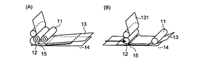
従来の方法では、図1に示すように、貼付ローラー及び剥離ローラーを取り付けているヘッドを下降させて、貼付ローラー及び剥離ローラーの両者で転写フィルムを基体に押し付ける工程(図1(A))を有するのに対し、本発明では、図2(A)に示すように、貼付ローラー11のみで転写フィルム13を基体14に押し付けることを特徴とする。すなわち、転写フィルムの貼付開始時点では、貼付ローラー11のみを、貼付開始点16で転写フィルム13を基体14に圧着させ、剥離ローラー12は基体14に圧着させないようにする。そして、貼付ローラー11を転写フィルム13に押し付けた状態で移動させ、転写フィルム13を基体14に貼付する。
一方、剥離ローラーは、図2(B)に示すように、貼付開始点16で転写フィルムに接触させる。すなわち、貼付ローラー11による転写フィルム13の貼付を開始した後、剥離ローラー12を貼付開始点16の上部まで移動させてから下降させて、該貼付開始点16で転写フィルム13と接触させ、その後剥離操作を行う。剥離操作の開始は、貼付ローラー11による転写フィルム13の貼付中であってもよいし、貼付操作が終了した後であってもよい。なお、後に詳述するように、貼付ローラー11の転写フィルム13に対する圧力を開放した後に剥離操作を行う方が好適であり、貼付操作終了後に剥離操作を行うことがより好ましい。
以上のような構成をとることで、転写フィルムと基体の間や転写フィルムの層間に空気が噛み込むことを抑制することができる。
The present invention relates to a method for producing a transfer body in which a transfer film composed of a release film and a transfer film is attached to a substrate using an application roller, and the release film is released using a release roller.
In the conventional method, as shown in FIG. 1, the process of lowering the head to which the sticking roller and the peeling roller are attached and pressing the transfer film against the substrate with both the sticking roller and the peeling roller (FIG. 1A) In contrast, in the present invention, as shown in FIG. 2A, the
On the other hand, the peeling roller is brought into contact with the transfer film at the sticking
By taking the configuration as described above, air can be prevented from being caught between the transfer film and the substrate or between the transfer films.
[空気噛み込みの機構]
本発明者らは、種々の検討の結果、空気の噛み込みが図3に示すような機構で生じることを発見し、この解決方法として、本発明を完成させたものである。
すなわち、図1に示すような従来の方法では、図3(A)に示すように、貼付ローラー及び剥離ローラーを取り付けているヘッドを下降させたときに、貼付ローラー11と剥離ローラー12の間の空間部で、転写フィルムと基体の間に空気が噛み込む場合がある(図3(A)15の部分)。そして、貼付ローラー11によって転写フィルム13を基体14に貼付し、その後剥離ローラー12を移動させて、剥離フィルム131を剥離する工程で、空気が搾り出されるようにして、剥離ローラー12が移動するために、転写フィルム13の各層の界面において凝集剥離が生じたり、転写フィルム13と基体14の間で剥離を生じることがある。
[Air entrainment mechanism]
As a result of various studies, the present inventors have discovered that air entrainment is caused by a mechanism as shown in FIG. 3, and completed the present invention as a solution.
That is, in the conventional method as shown in FIG. 1, when the head to which the sticking roller and the peeling roller are attached is lowered as shown in FIG. In the space portion, air may be caught between the transfer film and the substrate (
[本発明の作用効果]
上記従来技術に対して、本発明では、図2に示すように、貼付ローラー11のみで転写フィルム13を基体14に押し付けるために、貼付ローラー11と剥離ローラー12の間の空間部が存在しない。しかも、剥離ローラー12が転写フィルム13に最初に接触する部分(貼付開始点16)が、既に貼付ローラー11によって、基体14に貼付されているため、空気を噛み込むことがない。
[Effects of the present invention]
In contrast to the above prior art, in the present invention, as shown in FIG. 2, there is no space between the
本発明では、図4に示すように、転写フィルムとしてロール状のもの(以下「供給ロール」ということがある。)を用いることが好ましい。供給ロール30を用いる方法は、基体に対して、連続的に転写フィルムを供給することができ、生産性が高い。転写フィルムは、例えば図4に示すように、剥離フィルム131上の少なくとも一部に転写膜132が積層されてなり、このようなフィルムがコア(巻き芯)31に巻き取られる形で供給ロール30は構成される。なお、転写膜132は、基体の大きさに応じて、そのサイズが決定されるものであり、図4に示すように、転写膜間の転写膜がない部分はスペース部135と呼ばれる。
転写フィルムは、例えば、ベルトコンベアーにより搬送される基体に対して、供給ロールから供給され、本発明の方法で転写フィルムを貼付することで、転写体が製造される。
In the present invention, as shown in FIG. 4, it is preferable to use a roll-shaped transfer film (hereinafter sometimes referred to as “supply roll”). In the method using the
For example, the transfer film is supplied from a supply roll to a substrate transported by a belt conveyor, and a transfer body is manufactured by applying the transfer film by the method of the present invention.
[巻き取りローラー]
また、剥離フィルムは、図2に示すように、ガイドローラー17を介して、巻き取りローラー(図示せず)にて巻き取られる態様が好ましい。巻き取りローラーにて、剥離フィルムを巻き取りながら、剥離ローラーを移動させることで、効率的に剥離フィルムの剥離を行うことができ、高い生産性が得られる。
しかしながら、巻き取りローラーを用いる場合には、転写フィルムにテンションがかかり、図5に示すように剥離角度が小さくなる(図5の20の部分)。このように剥離角度が小さいと、剥離強度が強くなる傾向があり、転写フィルムを構成する転写膜に設けられた印刷パターンなどが破壊される場合がある。そこで、本発明では、図6に示すように、巻き取りローラーから剥離フィルムを送り、ガイドローラー17から基体に近い側、すなわち剥離ローラーの手前の部分で剥離フィルムをたるませ、剥離角度を大きくすることが好ましい。特に、剥離角度が180度であることが、印刷パターンへの影響が最も小さく好ましい。
[Winding roller]
Moreover, as shown in FIG. 2, the aspect with which a peeling film is wound up by the winding roller (not shown) via the
However, when a take-up roller is used, tension is applied to the transfer film, and the peeling angle becomes small as shown in FIG. 5 (
また、従来の方法では、貼付ローラー11と剥離ローラー12が同時に移動して、転写体を製造するために、図7に示すように、転写終了時点で、貼付ローラー11と剥離ローラー12が、同時に転写フィルム13に圧力をかけた状態になる。また、貼付ローラー11により転写フィルム13が貼付され、その後、剥離ローラー12の移動により、剥離フィルム131が剥離される場合でも、同様に貼付ローラー11と剥離ローラー12が、同時に転写フィルム13に圧力をかけた状態になる。
したがって、転写フィルム13と基体14が面接触し(図7の18の部分)、貼付ローラー11及び剥離ローラー12を備えるヘッドを上昇させたときに、基体14に強い力がかかり、基体14が割れる場合がある。
本発明では、図8に示すように、貼付ローラー11を移動して、転写フィルム13を基体14に貼付し、次いで、貼付ローラー11を上昇させ、転写フィルム13への圧力を解放する(図8(A))。その後、剥離ローラー12を移動させ、剥離フィルム131を剥離する態様が好ましい。このような態様をとることで、転写終了時点で、剥離ローラー12のみが転写フィルム13に接触しているため、線接触となり(図8の19の部分)、ヘッドの上昇時に転写フィルム13が基体14から容易に剥離する。
Further, in the conventional method, in order to move the sticking
Therefore, when the
In the present invention, as shown in FIG. 8, the sticking
[転写フィルム]
本発明で用いられる転写フィルムは、剥離フィルムと転写膜を有していれば特に限定されないが、例えば、図9に示すように、剥離フィルム131上に転写膜132が積層され、該転写膜132は、無機粉体と焼成除去可能な有機物を含有してなる機能性パターン133と、焼成除去可能な有機物よりなる粘着層134とを備える態様が挙げられる。
また、機能性パターン133と粘着層134の間に焼成除去可能な有機物からなる中間層を備えた態様や、機能性パターン133と剥離フィルム131の間に保護層を設けた態様がある。ここで、中間層は、粘着層の形成に使用される粘着剤に含有する溶剤や有機物の機能性パターンへの浸み込みを防止するバリア性の役割を担う。また、保護層は基体に転写した焼成前の機能性パターンを異物の付着や傷から保護する役割を担う。
[Transfer film]
The transfer film used in the present invention is not particularly limited as long as it has a release film and a transfer film. For example, as shown in FIG. 9, a
In addition, there are an aspect in which an intermediate layer made of an organic material that can be removed by baking is provided between the
[剥離フィルム]
剥離フィルムは機能性パターンを含む転写膜と剥離性を有するものであれば良く、フィルム基材をそのまま用いても良いが、必要によりフィルム基材上にシリコーン系やアルキド樹脂系などからなる剥離層や再剥離用の微粘着層を形成した構成であっても良い。
剥離フィルムの基材としては、転写時の施工性を考慮してフレキシブルな基材が好ましく、例えば、ポリエチレン、ポリイミド、ポリエチレンテレフタレート、アクリルなどのプラスチックや紙などが使用できる。また基材の厚みは特に限定されるものではないが、転写時の圧力や熱の伝達性とフィルムの屈曲性とのバランスの点から最適な厚みを選定すればよく、25〜250μm、好ましくは35〜125μm、さらに好ましくは50〜75μmが、製造上もしくは施工上好適に用いられる。
[Peeling film]
Any release film may be used as long as it has releasability from a transfer film containing a functional pattern, and the film base may be used as it is, but if necessary, a release layer made of a silicone or alkyd resin on the film base. Alternatively, a configuration in which a slightly adhesive layer for re-peeling is formed may be used.
As the substrate of the release film, a flexible substrate is preferable in consideration of the workability at the time of transfer, and for example, plastics such as polyethylene, polyimide, polyethylene terephthalate, and acrylic, and paper can be used. The thickness of the substrate is not particularly limited, and an optimum thickness may be selected from the viewpoint of the balance between the pressure and heat transferability during transfer and the flexibility of the film, preferably 25 to 250 μm, preferably 35-125 micrometers, More preferably, 50-75 micrometers is used suitably on manufacture or construction.
剥離フィルム上への機能性パターンや各層の形成方法は、スクリーン印刷やオフセット印刷などの印刷方式やグラビアコーティングなどの塗布方式を用いることができる。パターンを形成する場合は、上記印刷方法が好適に用いられ、広い面積に一様に層を形成する場合は、塗布方法も好適である。
上記印刷方法や塗布方法により、機能性パターンや各層を形成する場合は、これらに含有される無機粉体や有機物を溶剤中に分散または溶解してなる塗布液(ペースト)を作製し、使用する。溶剤としては、無機粉体や有機物の溶解性や分散性、そして印刷工程に適した沸点を考慮し、水系、アルコール系、ケトン系、エステル系、エーテル系、炭化水素系などを、単独または混合して使用することができる。そしてこれらの溶剤は、粘度やチキソ性など印刷適正、そして固形分を適宜調整して用いる。
As a method for forming the functional pattern and each layer on the release film, a printing method such as screen printing or offset printing or a coating method such as gravure coating can be used. When forming a pattern, the said printing method is used suitably, and when forming a layer uniformly in a wide area, the coating method is also suitable.
When forming a functional pattern or each layer by the above printing method or coating method, a coating liquid (paste) formed by dispersing or dissolving the inorganic powder or organic substance contained in the solvent is prepared and used. . In consideration of the solubility and dispersibility of inorganic powders and organic substances and the boiling point suitable for the printing process, water-based, alcohol-based, ketone-based, ester-based, ether-based, and hydrocarbon-based solvents can be used alone or in combination. Can be used. These solvents are used by appropriately adjusting the printing suitability such as viscosity and thixotropy and solid content.
[機能性パターン]
機能性パターンは、主に焼成後の機械的強度を発現するための基材に熱融着可能な無機粉体と、焼成後の所望の機能に応じた各種機能性材料としての無機粉体と、焼成前の形状を維持し、焼成除去される有機物とを含有する。
熱融着可能な無機粉体としては、各種機能性材料を焼成後に基体に担持させ、耐久性を向上させるなどの目的のために、ガラスフリットなどの材料が使用可能であり、焼成温度や熱収縮率などのバランスを考慮して、好適な組成のガラスフリットを選定すればよい。
[Functional pattern]
The functional pattern is mainly composed of inorganic powder that can be heat-sealed to a base material for expressing mechanical strength after firing, and inorganic powder as various functional materials according to desired functions after firing. The organic matter that maintains the shape before firing and is removed by firing is contained.
As the inorganic powder that can be heat-bonded, various functional materials are supported on a substrate after firing, and materials such as glass frit can be used for the purpose of improving durability, and firing temperature and heat A glass frit having a suitable composition may be selected in consideration of a balance such as a shrinkage rate.
機能性材料としては、焼成後の所望の機能に応じた材料を適宜選択して使用する。例えば、配線や電極などには、Au、Ag、Cu、Ni、Co、Sn、Pb、Zn、Bi、Inの粉体やこれらを含む合金の粉体を使用することが可能である。またコンデンサ部品などの誘電体や高抵抗部品などに使用される材料として、BaTiO、SiC、TiO2、SiO2、やRuOなどの粉体が挙げられる。 As the functional material, a material corresponding to a desired function after firing is appropriately selected and used. For example, powders of Au, Ag, Cu, Ni, Co, Sn, Pb, Zn, Bi, In or alloys containing these can be used for wirings and electrodes. Examples of materials used for dielectrics such as capacitor parts and high resistance parts include powders such as BaTiO, SiC, TiO2, SiO2, and RuO.
有機物としては、焼成除去可能な材料であれば特に限定されない。焼成による熱分解によって除去されやすい材料としては、アクリル、メチルセルロース、ニトロセルロース、エチルセルロース、酢酸ビニル、ポリビニルブチラール、ポリビニルアセタール、ポリビニルアルコール、ポリエチレンオキサイド、ポリエステルなどの樹脂が挙げられ、単独、またはこれらを混合して使用することができる。また有機成分として、焼成前の塗膜に可とう性を付与する目的で可塑剤を加えてもよい。可塑剤としては脂肪酸エステルやリン酸エステルなどから適宜選定して用いることができる。
機能性パターンは一つのパターンでも複数のパターンでもよく、複数のパターンを積層しても、個々に併設しても良い。機能性パターンの膜厚は、目的とする機能に合わせて適宜決定される。
The organic substance is not particularly limited as long as it is a material that can be removed by firing. Examples of materials that can be easily removed by thermal decomposition by firing include resins such as acrylic, methylcellulose, nitrocellulose, ethylcellulose, vinyl acetate, polyvinyl butyral, polyvinyl acetal, polyvinyl alcohol, polyethylene oxide, and polyester, either alone or in combination. Can be used. Moreover, you may add a plasticizer as an organic component in order to provide a flexibility to the coating film before baking. The plasticizer can be appropriately selected from fatty acid esters, phosphate esters, and the like.
The functional pattern may be a single pattern or a plurality of patterns, and a plurality of patterns may be laminated or individually provided. The film thickness of the functional pattern is appropriately determined according to the intended function.
粘着層は焼成除去可能な有機物で構成されていれば特に限定されないが、常温で粘着性を有するアクリル系、ゴム系などの粘着剤が使用できる。粘着層は剥離フィルムなどの支持体全面を覆うように形成しても良く、機能性パターン上に同様のパターンを形成してもよい。
粘着層の膜厚は、1〜20μmが好ましく、さらに好ましくは2〜10μmである。1μm以上であれば十分な粘着力が得られ、良好な転写性が得られる。一方、20μm以下であると、熱分解ガスの発生量が過多にならず、機能性パターンに欠陥が生じたり、焼成不良となることがない。なお、粘着層の膜厚は、粘着力を維持できる範囲で、できるだけ薄膜にすることが好ましい。
Although it will not specifically limit if the adhesion layer is comprised by the organic substance which can be baked and removed, Adhesives, such as an acrylic type and rubber type, which have adhesiveness at normal temperature can be used. The adhesive layer may be formed so as to cover the entire surface of the support such as a release film, or a similar pattern may be formed on the functional pattern.
The film thickness of the adhesive layer is preferably 1 to 20 μm, more preferably 2 to 10 μm. If it is 1 μm or more, sufficient adhesive strength can be obtained, and good transferability can be obtained. On the other hand, when it is 20 μm or less, the amount of pyrolysis gas generated does not become excessive, and defects in the functional pattern do not occur or firing defects do not occur. In addition, it is preferable to make the film thickness of the adhesive layer as thin as possible within the range where the adhesive force can be maintained.
[基体]
本発明の製造方法では、基体としては種々のものを用いることができ、特に制限はない。具体的には、ガラス基材などを用いることができるが、特に本発明の製造方法は、ガラス基材を基体とする場合に効果的である。ガラス基材は表面が平滑で通気性がないため、上述の問題点が生じやすいためである。
[Substrate]
In the production method of the present invention, various substrates can be used, and there is no particular limitation. Specifically, a glass substrate or the like can be used, but the production method of the present invention is particularly effective when the glass substrate is used as a substrate. This is because the glass substrate has a smooth surface and no air permeability, and thus the above-mentioned problems are likely to occur.
[転写機]
本発明の製造方法において用いられる転写機は、以下の構成を有する。
すなわち、本発明の転写機は、供給ローラー、貼付ローラー、剥離ローラー、該貼付ローラー及び該剥離ローラーを上下させる機構、貼付ローラー及び剥離ローラーを転写フィルムに圧力をかけながら供給ローラー側へ移動させる機構、及び転写フィルムを構成する剥離フィルムを剥離し、巻き取る機構を有し、転写フィルムの貼付開始時点では、貼付ローラーのみが転写フィルムを基体に押し付け、押し付けた状態で貼付ローラーを移動させて転写フィルムを基体に貼付し、剥離ローラーは貼付ローラーによる貼付開始点で転写フィルムに接触させ、該剥離ローラーを移動させて剥離フィルムを剥離することを特徴とするものである。
[Transfer machine]
The transfer machine used in the production method of the present invention has the following configuration.
That is, the transfer machine of the present invention includes a supply roller, a sticking roller, a peeling roller, a mechanism for moving the sticking roller and the peeling roller up and down, and a mechanism for moving the sticking roller and the peeling roller toward the supply roller while applying pressure to the transfer film. , And a mechanism for peeling and winding the release film constituting the transfer film. At the start of transfer film sticking, only the sticking roller presses the transfer film against the substrate and moves the sticking roller in the pressed state for transfer. The film is stuck to the substrate, the peeling roller is brought into contact with the transfer film at the sticking start point by the sticking roller, and the peeling film is peeled off by moving the peeling roller.
次に、本発明を実施例により、さらに詳細に説明するが、本発明は、この例によってなんら限定されるものではない。
実施例1
(1)転写フィルムの製造
以下の手順で、焼成用転写フィルムを作製した。
まず、剥離フィルムとして、シリコーン系離形層を設けたPETフィルム「A70」(帝人デュポンフィルム(株)製、フィルムサイズ3.5cm×30cm、厚み50μm)を用意した。次に、機能性パターンの塗布液として、導電性ペーストを3本ロールミルを用いて作成した。また、粘着層の塗布液としてアクリル系粘着剤「SK1451」(綜研化学工業(株)製)の溶媒をソルベッソ150で置換した粘着層ペーストを作製した。
次に、前記剥離フィルムの離形層上に、スクリーン印刷機を用いて前記導電性ペーストをサイズ2cm×5cm、膜厚15μmとなるように印刷し、機能性パターンを形成した。
次いで、剥離フィルムの剥離層側の全面に、該機能性パターンを覆うようにして、前記粘着層ペーストを厚さ10μmとなるようにメイヤーバーを用いて塗布し、接着層を形成した。そして、粘着層に含有される溶剤を十分に揮発させた。
粘着層と機能性パターンからなる転写膜が形成された剥離フィルムから、機能性パターンを含む部分をフィルムサイズ6cm×35cmに切り出し、実施例1の転写フィルムとした。
EXAMPLES Next, although an Example demonstrates this invention further in detail, this invention is not limited at all by this example.
Example 1
(1) Manufacture of transfer film A transfer film for baking was prepared by the following procedure.
First, a PET film “A70” (manufactured by Teijin DuPont Films, film size: 3.5 cm × 30 cm, thickness: 50 μm) provided with a silicone release layer was prepared as a release film. Next, as a functional pattern coating solution, a conductive paste was prepared using a three- roll mill. Moreover, the adhesive layer paste which substituted the solvent of acrylic adhesive "SK1451" (made by Soken Chemical Industry Co., Ltd.) with Solvesso 150 as a coating liquid of the adhesion layer was produced.
Next, on the release layer of the release film, the conductive paste was printed to a size of 2 cm × 5 cm and a film thickness of 15 μm using a screen printer to form a functional pattern.
Next, the adhesive layer paste was applied to the entire surface of the release film on the release layer side so as to cover the functional pattern using a Mayer bar so as to have a thickness of 10 μm, thereby forming an adhesive layer. And the solvent contained in the adhesion layer was volatilized sufficiently.
A part including the functional pattern was cut out into a film size of 6 cm × 35 cm from the release film on which the transfer film composed of the adhesive layer and the functional pattern was formed, and the transfer film of Example 1 was obtained.
(2)転写体の製造
基体としてフロート法により製造されたガラス板(サイズ30cm×30cm)を用意した。このガラス板の表面に、前記(1)で作製した直後の転写フィルムをその粘着層を向かい合わせて載置し、貼付ローラーのみを用いて、剥離フィルム上から0.5MPaの圧力で貼り合わせた。すなわち、貼付開始点において、貼付ローラーのみで転写フィルムをガラス板に0.5MPaで圧着させ、剥離ローラーはガラス板に圧着させないようにし、貼付ローラーを300mm/秒の速度で移動させて転写フィルムをガラス板に貼付した。
次に、貼付ローラーを転写フィルムから離間させた後、貼付開始点において、剥離ローラーをガラス板に0.5MPaの圧力で押し付けながら、300mm/秒の速度で移動させることで剥離フィルムを剥離し、転写体を製造した。次いで、該転写体を、焼成炉を用いて焼成した。焼成条件は、昇温速度20℃/minで室温から650℃まで昇温し、その温度を30分間維持した後、炉内放冷で100℃以下まで冷却した。
冷却された転写体(機能性パターン付きガラス板)を焼成炉から取り出し、目視にて確認したところ、転写フィルムとガラス板の界面の接着不良がなく、また転写フィルムの層間剥離も生じていなかった。また、機能性パターン及びガラス板に損傷はなかった。
(2) Production of transfer body A glass plate (
Next, after separating the sticking roller from the transfer film, at the sticking start point, the peeling roller is peeled off by moving at a speed of 300 mm / second while pressing the peeling roller against the glass plate at a pressure of 0.5 MPa, A transfer body was produced. Next, the transfer body was fired using a firing furnace. As firing conditions, the temperature was raised from room temperature to 650 ° C. at a rate of temperature rise of 20 ° C./min, maintained at that temperature for 30 minutes, and then cooled to 100 ° C. or less by standing in the furnace.
When the cooled transfer body (glass plate with a functional pattern) was taken out from the firing furnace and visually confirmed, there was no adhesion failure at the interface between the transfer film and the glass plate, and there was no delamination of the transfer film. . Further, the functional pattern and the glass plate were not damaged.
比較例1
実施例1において、貼付ローラーと剥離ローラーの両方で、転写フィルムをガラス板に0.5MPaで圧着させ、貼付ローラーを移動させて転写フィルムを貼付した後、貼付ローラーを離間させることなく、剥離ローラーを移動させて、剥離フィルムを剥離したこと以外は実施例1と同様にして転写体を製造した。
実施例1と同様に目視にて確認したところ、転写膜が部分的に又は全部が貼付かず、剥離フィルムに残るなどの点で問題があった。
Comparative Example 1
In Example 1, the transfer film was pressure-bonded to the glass plate at 0.5 MPa with both the application roller and the release roller, the application roller was moved to apply the transfer film, and then the release roller was not separated. Was transferred to produce a transfer body in the same manner as in Example 1 except that the release film was peeled off.
When visually confirmed in the same manner as in Example 1, there was a problem in that the transfer film was not partially or wholly adhered and remained on the release film.
本発明の製造方法によれば、転写フィルムと基体の間や転写フィルムの層間に空気が噛み込むことがなく、転写フィルムから剥離フィルムを剥離させる際に、転写膜を構成する機能性パターンが破壊されることがなく、また、貼付ローラー及び剥離ローラーを基体から離間させる際に、基体に損傷を与えることなく、高い生産性で転写体を製造することができる。
また、本発明の製造方法により得られる転写体は、転写フィルムと基体の界面の接着不良がなく、また転写フィルムの層間剥離がない。さらに、機能性パターンが破壊されず、基体に損傷も損傷がない。
本発明の転写機によれば、上記本発明の転写方法を行うことができ、高い生産性で転写体を製造することができる。
According to the manufacturing method of the present invention, the air does not bite between the transfer film and the substrate or between the transfer films, and the functional pattern constituting the transfer film is destroyed when the release film is peeled off from the transfer film. In addition, when the sticking roller and the peeling roller are separated from the substrate, the transfer body can be produced with high productivity without damaging the substrate.
Further, the transfer body obtained by the production method of the present invention has no adhesion failure at the interface between the transfer film and the substrate, and there is no delamination of the transfer film. Furthermore, the functional pattern is not destroyed and the substrate is not damaged or damaged.
According to the transfer machine of the present invention, the transfer method of the present invention can be performed, and a transfer body can be produced with high productivity.
11 貼付ローラー
12 剥離ローラー
13 転写フィルム
131 剥離フィルム
132 転写膜
133 機能性パターン
134 粘着層
135 スペース部
14 基体
15 空気の噛み込み
16 貼付開始点
17 ガイドローラー
18 面接触の状態
19 線接触の状態
20 剥離角度
30 供給ロール
31 コア(巻き芯)
DESCRIPTION OF
Claims (7)
Priority Applications (5)
| Application Number | Priority Date | Filing Date | Title |
|---|---|---|---|
| JP2010079859A JP5563349B2 (en) | 2010-03-30 | 2010-03-30 | Method for producing transfer body |
| CN2011800156870A CN102821958A (en) | 2010-03-30 | 2011-03-25 | Method for producing transfer body |
| PCT/JP2011/057464 WO2011122499A1 (en) | 2010-03-30 | 2011-03-25 | Method for producing transfer body |
| EP11762730A EP2554380A1 (en) | 2010-03-30 | 2011-03-25 | Method for producing transfer body |
| US13/637,503 US20130022819A1 (en) | 2010-03-30 | 2011-03-25 | Method for producing transfer body |
Applications Claiming Priority (1)
| Application Number | Priority Date | Filing Date | Title |
|---|---|---|---|
| JP2010079859A JP5563349B2 (en) | 2010-03-30 | 2010-03-30 | Method for producing transfer body |
Publications (3)
| Publication Number | Publication Date |
|---|---|
| JP2011207618A JP2011207618A (en) | 2011-10-20 |
| JP2011207618A5 JP2011207618A5 (en) | 2013-05-09 |
| JP5563349B2 true JP5563349B2 (en) | 2014-07-30 |
Family
ID=44712205
Family Applications (1)
| Application Number | Title | Priority Date | Filing Date |
|---|---|---|---|
| JP2010079859A Active JP5563349B2 (en) | 2010-03-30 | 2010-03-30 | Method for producing transfer body |
Country Status (5)
| Country | Link |
|---|---|
| US (1) | US20130022819A1 (en) |
| EP (1) | EP2554380A1 (en) |
| JP (1) | JP5563349B2 (en) |
| CN (1) | CN102821958A (en) |
| WO (1) | WO2011122499A1 (en) |
Families Citing this family (6)
| Publication number | Priority date | Publication date | Assignee | Title |
|---|---|---|---|---|
| JP6035599B2 (en) * | 2012-09-14 | 2016-11-30 | 株式会社トッパンTdkレーベル | Double-sided adhesive film |
| US9993023B2 (en) * | 2013-02-22 | 2018-06-12 | Altria Client Services Llc | Electronic smoking article |
| US10031183B2 (en) * | 2013-03-07 | 2018-07-24 | Rai Strategic Holdings, Inc. | Spent cartridge detection method and system for an electronic smoking article |
| US9839238B2 (en) * | 2014-02-28 | 2017-12-12 | Rai Strategic Holdings, Inc. | Control body for an electronic smoking article |
| CN107910290A (en) * | 2017-11-20 | 2018-04-13 | 浙江工业大学 | A kind of transfer brush method and device of microcosmic material |
| TWI758130B (en) * | 2021-03-15 | 2022-03-11 | 廣達電腦股份有限公司 | Composite automatic production equipment for in-mold placement process |
Family Cites Families (12)
| Publication number | Priority date | Publication date | Assignee | Title |
|---|---|---|---|---|
| US3655496A (en) * | 1969-09-25 | 1972-04-11 | Vitta Corp | Tape transfer of sinterable conductive, semiconductive or insulating patterns to electronic component substrates |
| JP2000246718A (en) * | 1999-03-02 | 2000-09-12 | Murata Mfg Co Ltd | Method for laminating ceramic green sheet and laminating device |
| JP3321129B2 (en) * | 1999-11-17 | 2002-09-03 | 富士通株式会社 | Three-dimensional structure transfer method and apparatus |
| JP3773751B2 (en) * | 2000-04-11 | 2006-05-10 | 松下電器産業株式会社 | Adhesive tape attaching device, component mounting machine and display panel |
| KR20040077655A (en) * | 2001-10-19 | 2004-09-06 | 슈페리어 마이크로파우더스 엘엘씨 | Tape compositions for the deposition of electronic features |
| US6690908B1 (en) * | 2002-10-25 | 2004-02-10 | Hewlett-Packard Development Company, L.P. | Print media coating device and method |
| JP4494753B2 (en) * | 2003-10-27 | 2010-06-30 | リンテック株式会社 | Sheet peeling apparatus and peeling method |
| CN100553424C (en) * | 2004-12-03 | 2009-10-21 | 日本特殊陶业株式会社 | The method and apparatus that comprises the production terminal block that film is peeled off |
| CN1872563A (en) * | 2005-06-02 | 2006-12-06 | 优立企业有限公司 | Transfer printing thin film in mould, and fabrication method |
| JP2007165379A (en) | 2005-12-09 | 2007-06-28 | Matsushita Electric Ind Co Ltd | Transfer device |
| JP5307360B2 (en) * | 2007-06-13 | 2013-10-02 | 株式会社トッパンTdkレーベル | Transfer film for firing and method for forming substrate with functional pattern |
| JP5482202B2 (en) * | 2008-03-14 | 2014-05-07 | 東レ株式会社 | Method and apparatus for producing film having fine uneven pattern on surface |
-
2010
- 2010-03-30 JP JP2010079859A patent/JP5563349B2/en active Active
-
2011
- 2011-03-25 CN CN2011800156870A patent/CN102821958A/en active Pending
- 2011-03-25 US US13/637,503 patent/US20130022819A1/en not_active Abandoned
- 2011-03-25 EP EP11762730A patent/EP2554380A1/en not_active Withdrawn
- 2011-03-25 WO PCT/JP2011/057464 patent/WO2011122499A1/en active Application Filing
Also Published As
| Publication number | Publication date |
|---|---|
| CN102821958A (en) | 2012-12-12 |
| US20130022819A1 (en) | 2013-01-24 |
| WO2011122499A1 (en) | 2011-10-06 |
| JP2011207618A (en) | 2011-10-20 |
| EP2554380A1 (en) | 2013-02-06 |
Similar Documents
| Publication | Publication Date | Title |
|---|---|---|
| JP5563349B2 (en) | Method for producing transfer body | |
| US9200183B2 (en) | Self-splitting splicing tape and dynamic splicing method using the same | |
| JP5307360B2 (en) | Transfer film for firing and method for forming substrate with functional pattern | |
| JP4084385B2 (en) | Method for manufacturing multilayer unit for multilayer electronic component | |
| JP5992069B2 (en) | Transfer film used for manufacturing a patterned glass substrate | |
| JP5956220B2 (en) | Label sheet, method for producing the same, and method for producing an article with a printed pattern | |
| JP5229529B2 (en) | Transfer film for firing and method for forming substrate with functional pattern | |
| JP6520143B2 (en) | Laminate, method of manufacturing conductive substrate using the same, method of manufacturing electronic device, and transfer tool | |
| JP6699784B2 (en) | Laminated body, method of manufacturing conductive substrate using the same, method of manufacturing electronic device, and transfer tool | |
| JP5600458B2 (en) | Manufacturing method of glass plate provided with transfer-type film for baking and fired body | |
| US20100086752A1 (en) | Transfer Films for Firing and Method of Forming Substrate with Functional Pattern | |
| JP5830033B2 (en) | Glass substrate with pattern and method for manufacturing the same | |
| JP5369329B2 (en) | Transfer film for baking | |
| JP5040031B2 (en) | Transfer film for baking | |
| JP6057622B2 (en) | Label sheet with transfer label | |
| JP3921454B2 (en) | Method for manufacturing multilayer unit for multilayer ceramic electronic component and multilayer unit for multilayer ceramic electronic component | |
| JP2019114674A (en) | Manufacturing method of wiring board | |
| JP2005159101A (en) | Method of manufacturing laminate unit for laminated electronic component and method of manufacturing laminate unit set for laminated electronic component containing the laminate unit | |
| JP4142686B2 (en) | Method for manufacturing multilayer unit for multilayer electronic component | |
| JP2005159100A (en) | Method of manufacturing laminate unit for laminated electronic component and method of manufacturing laminate unit set for laminated electronic component containing the laminate unit | |
| JP2005159098A (en) | Method of manufacturing laminate unit for laminated electronic component, method of manufacturing laminte unit set for laminated electronic component containing the laminate unit | |
| JP2020032613A (en) | Method for producing laminate and laminate | |
| JP2005079229A (en) | Method of manufacturing laminate unit for laminated electronic component and method of manufacturing laminate unit set for laminated electronic component containing at least one laminate unit | |
| JP2005159099A (en) | Method of manufacturing laminate unit for laminated electronic component, method of manufacturing laminate unit set for laminated electronic component containing the laminate unit, and laminated electronic component manufacturing device | |
| JP2005159096A (en) | Method of manufacturing laminate unit for laminated electronic component, method of manufacturing laminate unit set for laminated electronic component containing the laminate unit, and laminated electronic component manufacturing device |
Legal Events
| Date | Code | Title | Description |
|---|---|---|---|
| A521 | Request for written amendment filed |
Free format text: JAPANESE INTERMEDIATE CODE: A523 Effective date: 20130325 |
|
| A621 | Written request for application examination |
Free format text: JAPANESE INTERMEDIATE CODE: A621 Effective date: 20130325 |
|
| A131 | Notification of reasons for refusal |
Free format text: JAPANESE INTERMEDIATE CODE: A131 Effective date: 20140121 |
|
| A521 | Request for written amendment filed |
Free format text: JAPANESE INTERMEDIATE CODE: A523 Effective date: 20140320 |
|
| TRDD | Decision of grant or rejection written | ||
| A01 | Written decision to grant a patent or to grant a registration (utility model) |
Free format text: JAPANESE INTERMEDIATE CODE: A01 Effective date: 20140520 |
|
| A61 | First payment of annual fees (during grant procedure) |
Free format text: JAPANESE INTERMEDIATE CODE: A61 Effective date: 20140612 |
|
| R150 | Certificate of patent or registration of utility model |
Ref document number: 5563349 Country of ref document: JP Free format text: JAPANESE INTERMEDIATE CODE: R150 |
|
| R250 | Receipt of annual fees |
Free format text: JAPANESE INTERMEDIATE CODE: R250 |
|
| R250 | Receipt of annual fees |
Free format text: JAPANESE INTERMEDIATE CODE: R250 |
|
| R250 | Receipt of annual fees |
Free format text: JAPANESE INTERMEDIATE CODE: R250 |
|
| S531 | Written request for registration of change of domicile |
Free format text: JAPANESE INTERMEDIATE CODE: R313531 |
|
| S533 | Written request for registration of change of name |
Free format text: JAPANESE INTERMEDIATE CODE: R313533 |
|
| R350 | Written notification of registration of transfer |
Free format text: JAPANESE INTERMEDIATE CODE: R350 |
|
| R250 | Receipt of annual fees |
Free format text: JAPANESE INTERMEDIATE CODE: R250 |
|
| R250 | Receipt of annual fees |
Free format text: JAPANESE INTERMEDIATE CODE: R250 |
|
| R250 | Receipt of annual fees |
Free format text: JAPANESE INTERMEDIATE CODE: R250 |
|
| R250 | Receipt of annual fees |
Free format text: JAPANESE INTERMEDIATE CODE: R250 |