JP5561524B2 - Image processing apparatus and method, and program - Google Patents
Image processing apparatus and method, and program Download PDFInfo
- Publication number
- JP5561524B2 JP5561524B2 JP2010065117A JP2010065117A JP5561524B2 JP 5561524 B2 JP5561524 B2 JP 5561524B2 JP 2010065117 A JP2010065117 A JP 2010065117A JP 2010065117 A JP2010065117 A JP 2010065117A JP 5561524 B2 JP5561524 B2 JP 5561524B2
- Authority
- JP
- Japan
- Prior art keywords
- blocks
- image
- block
- histogram
- change
- Prior art date
- Legal status (The legal status is an assumption and is not a legal conclusion. Google has not performed a legal analysis and makes no representation as to the accuracy of the status listed.)
- Expired - Fee Related
Links
Images


Classifications
-
- G—PHYSICS
- G06—COMPUTING; CALCULATING OR COUNTING
- G06T—IMAGE DATA PROCESSING OR GENERATION, IN GENERAL
- G06T7/00—Image analysis
- G06T7/0002—Inspection of images, e.g. flaw detection
- G06T7/0004—Industrial image inspection
- G06T7/001—Industrial image inspection using an image reference approach
-
- G—PHYSICS
- G06—COMPUTING; CALCULATING OR COUNTING
- G06T—IMAGE DATA PROCESSING OR GENERATION, IN GENERAL
- G06T7/00—Image analysis
- G06T7/20—Analysis of motion
- G06T7/254—Analysis of motion involving subtraction of images
-
- G—PHYSICS
- G06—COMPUTING; CALCULATING OR COUNTING
- G06T—IMAGE DATA PROCESSING OR GENERATION, IN GENERAL
- G06T2207/00—Indexing scheme for image analysis or image enhancement
- G06T2207/30—Subject of image; Context of image processing
- G06T2207/30232—Surveillance
Landscapes
- Engineering & Computer Science (AREA)
- Computer Vision & Pattern Recognition (AREA)
- Physics & Mathematics (AREA)
- General Physics & Mathematics (AREA)
- Theoretical Computer Science (AREA)
- Quality & Reliability (AREA)
- Multimedia (AREA)
- Closed-Circuit Television Systems (AREA)
- Image Analysis (AREA)
- Two-Way Televisions, Distribution Of Moving Picture Or The Like (AREA)
Description
本発明は画像処理装置および方法、並びにプログラムに関し、特に少ない記憶容量で画像の変化を検出することができるようにした画像処理装置および方法、並びにプログラムに関する。 The present invention relates to an image processing apparatus, method, and program, and more particularly, to an image processing apparatus, method, and program that can detect a change in an image with a small storage capacity.
所定の空間への人、動物などの侵入者を発見するために、監視カメラにより対象とされる空間を撮影し、撮影画像から侵入者を検知する監視システムが知られている。かかる監視システムは、妨害行為により監視カメラの向きが本来の方向から変更されてしまうと、監視ができなくなる。 In order to find an intruder such as a person or an animal in a predetermined space, a monitoring system is known in which a target space is photographed by a surveillance camera and the intruder is detected from the photographed image. Such a monitoring system cannot be monitored if the direction of the monitoring camera is changed from the original direction due to an obstruction.
そこで監視カメラにより撮像された現在の画像と予め記憶されている参照画像の輝度値の差分を演算し、差分値が一定値以上である場合には、妨害行為があったと判定することが提案されている(例えば特許文献1)。 Therefore, it is proposed to calculate the difference between the luminance value of the current image captured by the surveillance camera and the reference image stored in advance, and to determine that there is an obstruction if the difference value is greater than or equal to a certain value. (For example, Patent Document 1).
図1は、監視カメラにより撮像された画像の更新を説明する図である。図1に示されるように、フレームF1乃至フレームF6が順次得られたとき、例えば1フレームおきに得られる画像が参照画像として記憶され、順次更新される。すなわち、この例の場合、フレームF1,F3,F5が参照画像として順次更新される。 FIG. 1 is a diagram for explaining the update of an image captured by the surveillance camera. As shown in FIG. 1, when frames F1 to F6 are sequentially obtained, for example, images obtained every other frame are stored as reference images and sequentially updated. That is, in this example, the frames F1, F3, and F5 are sequentially updated as reference images.
妨害行為が存在しない場合、時間的に前の背景画像と時間的に後の背景画像とは同じであるので、輝度値の差分は小さい。これに対して、妨害行為により監視カメラの向きが変更された場合、時間的に前の背景画像と時間的に後の背景画像とは異なったものとなるので、輝度値の差分は大きくなる。 When there is no disturbing action, the difference between the luminance values is small because the temporally preceding background image and the temporally subsequent background image are the same. On the other hand, when the direction of the monitoring camera is changed due to an obstruction, the difference between the brightness values increases because the temporally previous background image and temporally subsequent background image are different.
そこで、フレームF3が得られたとき、そのときの過去の画像である参照画像としてのフレームF1との輝度値の差分が演算される。同様に、フレームF5が得られたとき、そのときの過去の画像であるフレームF3の画像との輝度値の差分が演算される。大きな差分値が得られたとき、妨害行為があったと判定される。 Therefore, when the frame F3 is obtained, the difference in luminance value from the frame F1 as the reference image, which is the past image at that time, is calculated. Similarly, when the frame F5 is obtained, the difference in luminance value from the image of the frame F3 that is the past image at that time is calculated. When a large difference value is obtained, it is determined that there has been an obstruction.
しかしながら現在の画像と参照画像の輝度値の差を演算することで妨害行為を検出するためには、参照画像を記憶する必要があるが、参照画像を記憶するためには記憶容量が大きいメモリを用意しなければならず、システムが高価になる。 However, in order to detect the disturbing action by calculating the difference between the luminance values of the current image and the reference image, it is necessary to store the reference image, but in order to store the reference image, a memory having a large storage capacity is required. It must be prepared and the system becomes expensive.
本発明はこのような状況に鑑みてなされたものであり、少ない記憶容量で、低コストで画像の変化を検出することができるようにするものである。 The present invention has been made in view of such a situation, and makes it possible to detect a change in an image at a low cost with a small storage capacity.
本発明の一側面は、画像の画像データを取得する取得手段と、取得された前記画像をN(N>1)個のブロックに分割する分割手段と、新たな前記画像の前記画像データが取得される毎に、N個の前記ブロックのうちの一部のM(M>1)個の前記ブロックを、更新する前記ブロックとして順次指定する際に、順次指定するM個の前記ブロックのうち、少なくとも2つの前記ブロックの前記画像上の位置が所定の関係を有して変化するように、前記ブロックを指定する指定手段と、指定されたM個の前記ブロックのヒストグラムを演算するヒストグラム演算手段と、演算された前記ブロックの前記ヒストグラムを順次更新して保存するヒストグラム保存手段と、演算された前記ブロックの前記ヒストグラムと、保存されていた対応する過去の前記ブロックの前記ヒストグラムの類似度が、類似度閾値よりも小さいフレームが少なくとも1フレーム存在する場合、取得された前記画像に変化があったと判定する変化判定手段とを備える画像処理装置である。 One aspect of the present invention is an acquisition unit that acquires image data of an image, a dividing unit that divides the acquired image into N (N> 1) blocks, and the image data of a new image is acquired. When each of the M blocks (M> 1) among the N blocks is sequentially designated as the block to be updated, among the M blocks to be sequentially designated, Designation means for designating the block so that positions of the at least two blocks on the image change with a predetermined relationship; and histogram calculation means for computing histograms of the designated M blocks. , a histogram storage means for storing said histogram of the computed said block sequentially update, said histogram of the computed said block, the corresponding past that were stored The similarity of the histogram of the serial block is smaller frame than the similarity threshold is an image processing apparatus and at least when a frame is present, determines the change determination means that there is a change in the acquired image.
前記指定手段は、順次指定するM個の前記ブロックのうち、少なくとも2つの前記ブロックの前記画像上の位置の変化の方向が異なるように、前記ブロックを指定することができる。 The designation means can designate the blocks such that at least two of the M blocks to be sequentially designated have different directions of change in position on the image.
前記指定手段は、前記指定手段は、M=4とし、前記画像を4つのグループに区分し、各グループから1つの前記ブロックを指定することができる。 The designating unit can set M = 4, divide the image into four groups, and designate one block from each group.
前記分割手段は、前記グループにおいて、できるだけ離れた位置の前記ブロックを先に選択することで前記ブロックを順次指定することができる。 The dividing means can sequentially designate the blocks by first selecting the blocks at positions as far apart as possible in the group.
前記分割手段は、前記ブロックを、前記変化の方向に対して平行な辺より垂直な辺が長くなるように分割することができる。 The dividing unit can divide the block such that a side perpendicular to the direction parallel to the direction of change is longer.
前記変化判定手段は、演算された前記ブロックの前記ヒストグラムと、保存されていた過去の前記ブロックの前記ヒストグラムの前記類似度を演算する類似度演算手段と、演算された前記類似度を類似度閾値と比較し、前記類似度が前記類似度閾値より小さいとき、前記画像の前記ブロックに変化があったと判定する類似度閾値判定手段とを備えることができる。 The change determination means includes a similarity calculation means for calculating the similarity of the calculated histogram of the block, and the histogram of the stored past block, and the calculated similarity as a similarity threshold. compared to, may be the similarity is smaller than the similarity threshold, and a similarity threshold determination means determines that the there was a block change in the image.
前記画像に変化があったとき、アラームを出力するアラーム出力手段をさらに備えることができる。 An alarm output means for outputting an alarm when there is a change in the image can be further provided.
前記アラーム出力手段は、変化があったと判定された前記ブロックの数をカウントするカウント手段と、前記カウント手段によりカウントされた値をアラーム閾値と比較し、前記カウントされた値が前記アラーム閾値より大きいとき前記アラームを出力するアラーム閾値判定手段とを備えることができる。 The alarm output means counts the number of the blocks determined to have changed, compares the value counted by the count means with an alarm threshold value, and the counted value is larger than the alarm threshold value. And an alarm threshold value judging means for outputting the alarm.
本発明の一側面の画像処理方法及びプログラムは、上述した本発明の一側面の画像処理装置に対応する方法及びプログラムである。 An image processing method and program according to one aspect of the present invention are a method and program corresponding to the above-described image processing apparatus according to one aspect of the present invention.
本発明の側面においては、画像の画像データが取得され、取得された画像がN(N>1)個のブロックに分割され、新たな画像の画像データが取得される毎に、N個のブロックのうちの一部のM(M>1)個のブロックが、更新するブロックとして順次指定される際に、順次指定するM個のブロックのうち、少なくとも2つのブロックの画像上の位置が所定の関係を有して変化するように、ブロックが指定され、指定されたM個のブロックのヒストグラムが演算され、演算されたブロックのヒストグラムが順次更新して保存される。演算されたブロックのヒストグラムと、保存されていた対応する過去のブロックのヒストグラムの類似度が、類似度閾値よりも小さいフレームが少なくとも1フレーム存在する場合、取得された画像に変化があったと判定される。 In an aspect of the present invention, image data of an image is acquired, the acquired image is divided into N (N> 1) blocks, and N blocks are obtained each time new image data is acquired. When some M (M> 1) blocks are sequentially designated as blocks to be updated, positions of at least two blocks of the sequentially designated M blocks are predetermined. The blocks are designated so as to change in a relational manner, the histograms of the designated M blocks are calculated, and the calculated histograms of the blocks are sequentially updated and stored. A histogram calculation block, the similarity of the histogram of the corresponding past block has been saved, if smaller frame than the similarity threshold is present at least one frame, it is determined that there is a change in the acquired image The
以上のように、本発明の一側面によれば、少ない記憶容量で、低コストで画像の変化を検出することができる As described above, according to one aspect of the present invention, it is possible to detect a change in an image at a low cost with a small storage capacity.
[変化領域検出の原理] [Principle of change area detection]
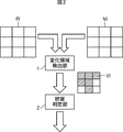
図2は変化領域検出の原理を説明する図である。本発明の一実施の形態においては、過去の画像PIと、現在の画像NIが変化領域検出部1に入力される。変化領域検出部1は過去の画像PIと現在の画像NIのそれぞれを、所定の大きさのブロックに分割する。そして各ブロック毎に画素値のヒストグラムが演算される。過去の画像PIの所定の位置のブロックのヒストグラムと、現在の画像NIの対応する位置のブロックのヒストグラムの類似度が演算される。類似度が低いブロックは変化領域VIとして検出される。
FIG. 2 is a diagram for explaining the principle of change area detection. In one embodiment of the present invention, the past image PI and the current image NI are input to the change
妨害判定部2は変化領域VIの数が多い場合、妨害行為があったと判定し、アラームを出力する。
When the number of change areas VI is large, the
[画像処理装置の構成] [Configuration of image processing apparatus]
図3は、本発明の画像処理装置の一実施の形態の構成を示すブロック図である。この画像処理装置21は、取得部31と画像処理部32により構成されている。
FIG. 3 is a block diagram showing the configuration of an embodiment of the image processing apparatus of the present invention. The
画像の画像データを取得する取得手段としての取得部31は、カメラ、ビデオカメラなどの撮像部を内蔵し、撮像部が監視する対象空間などの被写体を撮影することで得られた画像データを取得し、出力する。取得部31は、またネットワークを介して外部から供給される画像データを取得することもできる。
The
画像処理部32は、撮像信号処理部41、データ保存部42、および画像解析部43により構成される。
The
例えばDSP(Digital Signal Processor)により構成される撮像信号処理部41は、取得部31より得られた画像データに対して、黒レベル補正処理、ホワイトバランス処理、γ補正処理、色補正処理等の各種画像処理を施す。例えばRAM(Random Access Memory)により構成されるデータ保存部42は、撮像信号処理部41により処理された画像データを保存する。例えばCPU(Central Processing Unit)により構成される画像解析部43は、撮像信号処理部41より供給される現在の画像と、データ保存部42より供給される過去の画像である参照画像を解析する。
For example, the imaging
[画像解析部の構成] [Configuration of Image Analysis Unit ]
図4は、画像解析部43の機能的構成を示すブロック図である。画像解析部43は、更新領域選択部61、ヒストグラム保存部62、画像分割部63、ヒストグラム演算部64、変化判定部65、変化領域保存部66、およびアラーム出力部67により構成されている。
FIG. 4 is a block diagram illustrating a functional configuration of the
なお、図4に示す構成の全部または一部は、画像解析部43ではなく映像信号処理部41またはデータ保存部62に設けることもできる。ヒストグラム保存部62は、図3のデータ保存部42に対応する。
4 may be provided not in the
更新領域選択部61は、新たな画像の画像データが取得される毎に、N個のブロックのうちの一部のM(M>1)個のブロックを、更新するブロックとして順次指定する指定手段として機能する。この更新新領域選択部61は、撮像信号処理部41から供給されるデータから、取得部31により取得された画像のフレーム番号を抽出し、更新するフレーム番号を決定する。さらに更新領域選択部61は、更新するフレームの中の更新するブロックを決定する。取得された画像をN(N>1)個のブロックに分割する分割手段としての画像分割部63は、撮像信号処理部41から供給される画像データに基づく各フレームの画像のうち、更新領域選択部61により指定されるフレームを複数のブロックに分割する。画像分割部63はまた、分割されたブロックのうち、更新領域選択部61により指定されるブロックの画像データを、ヒストグラム演算部64に供給する。
The
取得された画像データのヒストグラムを演算するヒストグラム演算手段としてのヒストグラム演算部64は、画像分割部63から供給されたブロックのヒストグラムを演算する。なお、撮像信号処理部41がヒストグラム演算機能を備える場合がある。その場合には、ヒストグラム演算部64は撮像信号処理部41内に設けることができる。
A
演算されたヒストグラムを順次更新して保存するヒストグラム保存手段としてのヒストグラム保存部62は、更新領域選択部61により更新領域として指定されるブロックのヒストグラムを更新する。すなわち、ヒストグラム演算部64から供給される現在のフレームの更新対象のブロックのヒストグラムにより、既に記憶されている過去のフレームの対応するブロックのヒストグラムが書き換えられる。
A
演算されたヒストグラムと、保存されていた過去のヒストグラムの類似度に基づいて、取得された画像の変化を判定する変化判定手段としての変化判定部65は変化判定処理を行う。すなわち、ヒストグラム演算部64より供給される現在のフレームの更新対象のブロックのヒストグラムと、ヒストグラム保存部62から供給される過去のフレームの対応するブロックのヒストグラムに基づいて、画像の変化が判定される。変化領域保存部66は、変化判定部65による判定結果を保存する。
A
画像に変化があったとき、アラームを出力するアラーム出力手段としてのアラーム出力部67は、カウンタ部91と閾値判定部92により構成されている。
An
変化があったと判定されたブロックの数をカウントするカウント手段としてのカウンタ部91は、変化判定部65の出力と変化領域保存部66の出力に基づいて、1つの監視中の画像中の変化があったブロックの数をカウントする。カウントされた値をアラーム閾値と比較し、カウントされた値がアラーム閾値より大きいときアラームを出力するアラーム閾値判定手段としての閾値判定部92は、カウンタ部91によりカウントされたブロックの数を、予め決められている所定の閾値と比較する。カウントされたブロックの数が閾値より大きいとき、妨害行為が検出されたと判断し、検出信号が出力される。この検出信号は例えばアラームとすることができる。
A
[変化判定部の構成] [Configuration of change judgment unit]
図5は、変化判定部の機能的構成を示すブロック図である。変化判定部65は、類似度演算部111と、閾値判定部112とにより構成されている。
FIG. 5 is a block diagram illustrating a functional configuration of the change determination unit. The
類似度演算部111は、演算されたブロックのヒストグラムと、保存されていた過去のブロックのヒストグラムの類似度を演算する類似度演算手段として機能する。この類似度演算部111は、ヒストグラム演算部64から供給される現在のブロックのヒストグラムh1と、ヒストグラム保存部62より供給される過去の対応する位置のブロックのヒストグラムh0との類似度を演算する。演算された類似度を類似度閾値と比較し、類似度が類似度閾値より小さいとき、画像のブロックに変化があったと判定する類似度閾値判定手段としての閾値判定部112は、演算された類似度と予め定められている所定の閾値とを比較し、比較結果に基づいて検出信号を出力する。
The
[変化判定処理] [Change judgment processing]
図6は、変化判定処理を説明するフローチャートである。次にこの図を参照して変化判定処理を説明する。 FIG. 6 is a flowchart for explaining the change determination process. Next, the change determination process will be described with reference to FIG.
ステップS1において取得部31はカメラ画像を取得する。すなわち撮像部が所定の監視対象を撮像しており、その撮像画像の画像データが取得される。
In step S1, the
ステップS2において画像分割部63は、N個のブロックに画像を分割する。この実施の形態においては、画像データに基づく各フレームの画像が8×8個のブロックに分割される。
In step S2, the
ステップS3において更新領域選択部61は、更新領域を選択する。すなわち、8×8個のブロックのうちの所定のM(M<N)個のブロックが、更新対象のブロックとして選択される。この更新領域の選択について、図7を参照して説明する。
In step S3, the update
図7は、更新するブロックの移動を説明する図である。この実施の形態においては、M=4とされ、8×8個のブロックが4×4個のブロックからなる4個のグループに区分される。そして、各グループから1個のブロックが選択されて、合計4個のブロックが更新対象のブロックとして選択される。具体的には、図7Aに示されるように、更新領域選択部61は、最初のフレームの8×8個のブロックのうちの、1行目の最も左側に位置するブロックb11、最も右側に位置するブロックb18、8行目の最も左側に位置するブロックb81、最も右側に位置するブロックb88の4つのブロックを更新ブロックとして選択する。
FIG. 7 is a diagram for explaining the movement of the block to be updated. In this embodiment, M = 4, and 8 × 8 blocks are divided into 4 groups of 4 × 4 blocks. Then, one block is selected from each group, and a total of four blocks are selected as blocks to be updated. Specifically, as illustrated in FIG. 7A, the update
なお、図7において、上からi番目の行に位置し、左からj番目の列に位置するブロックを、bijのように表す。後述する図11乃至図18においても同様とする。 In FIG. 7, a block located in the i-th row from the top and located in the j-th column from the left is represented as bij. The same applies to FIGS. 11 to 18 described later.
次に図7Bに示されるように、更新領域選択部61は、次のフレームの8×8個のブロックのうちの、1行目の最も左側に位置するブロックb11の1つ右側に位置するブロックb12、最も右側に位置するブロックb18の1つ左側に位置するブロックb17、8行目の最も左側に位置するブロックb81の1つ右側に位置するブロックb82、最も右側に位置するブロックb88の1つ左側に位置するブロックb87の4つのブロックを更新ブロックとして選択する。
Next, as illustrated in FIG. 7B, the update
次に図7Cに示されるように、更新領域選択部61は、次のフレームの8×8個のブロックのうちの、1行目のブロックb12の1つ右側に位置するブロックb13、ブロックb17の1つ左側に位置するブロックb16、8行目のブロックb82の1つ右側に位置するブロックb83、ブロックb87の1つ左側に位置するブロックb86の4つのブロックを更新ブロックとして選択する。
Next, as illustrated in FIG. 7C, the update
次に図7Dに示されるように、更新領域選択部61は、次のフレームの8×8個のブロックのうちの、1行目のブロックb13の1つ右側に位置するブロックb14、ブロックb16の1つ左側に位置するブロックb15、8行目のブロックb83の1つ右側に位置するブロックb84、ブロックb86の1つ左側に位置するブロックb85の4つのブロックを更新ブロックとして選択する。
Next, as illustrated in FIG. 7D, the update
以上のようにして最上行と最下行におけるブロックの選択、移動が終了すると、次に第2行目と第7行目とが選択される。そして図7Eに示されるように、更新領域選択部61は、次のフレームの8×8個のブロックのうちの、2行目の最も左側に位置するブロックb21、最も右側に位置するブロックb28、7行目の最も左側に位置するブロックb71、最も右側に位置するブロックb78の4つのブロックを更新ブロックとして選択する。
When the selection and movement of the blocks in the top row and the bottom row are completed as described above, the second row and the seventh row are then selected. Then, as shown in FIG. 7E, the update
次に図7Fに示されるように、更新領域選択部61は、次のフレームの8×8個のブロックのうちの、2行目のブロックb21の1つ右側に位置するブロックb22、ブロックb28の1つ左側に位置するブロックb27、7行目のブロックb71の1つ右側に位置するブロックb72、ブロックb78の1つ左側に位置するブロックb77の4つのブロックを更新ブロックとして選択する。
Next, as illustrated in FIG. 7F, the update
以下、同様の手順により、更新対象のブロックとして、1フレームにおいて4個のブロックが順次選択される。すなわち、左側半分の上側半分の領域においては、行内においては左から右方向に、そして行は上から下方向に順次選択される。右側半分の上側半分の領域においては、行内においては右から左方向に、そして行は上から下方向に順次選択される。左側半分の下側半分の領域においては、行内においては左から右方向に、そして行は下から上方向に順次選択される。右側半分の下側半分の領域においては、行内においては右から左方向に、そして行は下から上方向に順次選択される。 Thereafter, four blocks in one frame are sequentially selected as the update target block by the same procedure. That is, in the upper half region of the left half, the rows are sequentially selected from left to right and rows from top to bottom. In the upper half region of the right half, the rows are selected sequentially from right to left and rows from top to bottom. In the lower half region of the left half, the rows are selected sequentially from left to right and rows from bottom to top. In the lower half area of the right half, the rows are selected sequentially from right to left and rows from bottom to top.
図6に戻って、ステップS4においてヒストグラム演算部64は、更新領域のヒストグラムを演算する。
Returning to FIG. 6, in step S <b> 4, the
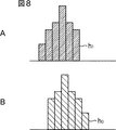
図8は、ヒストグラムの例を示す図である。横軸は輝度値に代表される画素値を表し、縦軸は所定の範囲の画素値を有する画素の数を表している。図8Aは、ヒストグラム演算部64により演算された現在のフレームの更新対象の1つのブロックのヒストグラムの例を示している。図8Bは、ヒストグラム保存部62に保存されている過去のフレームの対応する位置のブロックのヒストグラムの例を示している。
FIG. 8 is a diagram illustrating an example of a histogram. The horizontal axis represents pixel values represented by luminance values, and the vertical axis represents the number of pixels having pixel values in a predetermined range. FIG. 8A shows an example of a histogram of one block to be updated in the current frame calculated by the
ステップS5においてヒストグラム保存部62は、ステップS4で演算されたヒストグラムを保存する。ヒストグラム保存部62は、過去のデータをヒストグラムとして保存するので、例えば画素値などの画像データとして保存する場合に比べて、記憶容量を小さくし、低コスト化することができる。
In step S5, the
ステップS6において類似度演算部111は、ステップS4で演算された、現在のフレームの更新対象の1つのブロックのヒストグラムh1と、ヒストグラム保存部62に保存されている過去のフレームの対応する位置のブロックのヒストグラムh0の類似度を演算する。
In step S <b> 6, the
この実施の形態においては、インタセクションにより次式に基づいて類似度が演算される。すなわち各画素値において、画素の数が小さい方の和が求められる。下記式(1)の値Dは、類似度が高いとき大きくなり、類似度が低いとき小さくなる。下記式(1)のAi,Biは、それぞれ現在のフレームの更新対象の1つのブロックのヒストグラムh1の1つの画素値と、ヒストグラム保存部62に保存されている過去の1フレームの対応する位置のブロックのヒストグラムh0の1つの画素値を表している。この比較処理は、直近の過去のN(N>1)フレームについて行われる。
D=Σmin(Ai,Bi) (1)
In this embodiment, similarity is calculated based on the following equation by intersection. That is, for each pixel value, the sum of the smaller number of pixels is obtained. The value D of the following formula (1) increases when the similarity is high and decreases when the similarity is low. Ai and Bi in the following formula (1) are respectively the pixel value of the histogram h1 of one block to be updated in the current frame and the corresponding position of the past one frame stored in the
D = Σmin (Ai, Bi) (1)
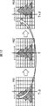
図9はヒストグラムの類似度を説明する図である。図9Aに示されるように、ヒストグラムh1とヒストグラムh0の殆どが重なっている場合、式(1)で演算される値Dは、大きくなる。それに対して、図9Bに示されるように、ヒストグラムh1とヒストグラムh0の重なりが少ない場合、値Dは小さくなる。 FIG. 9 is a diagram for explaining the similarity of histograms. As shown in FIG. 9A, when most of the histogram h1 and the histogram h0 overlap, the value D calculated by Expression (1) becomes large. On the other hand, as shown in FIG. 9B, when the overlap between the histogram h1 and the histogram h0 is small, the value D is small.
ステップS7において閾値判定部112は、変化領域を判定する。すなわち、ステップS6で演算された類似度Dが、予め定められた所定の閾値Thdと比較される。類似度Dが閾値Thdより小さいとき、そのブロックは変化があった領域であると判定される。直近の過去のNフレームのうち、類似度Dが閾値Thdより小さいフレームが1フレームでもあった場合、領域に変化があったと判定される。
In step S7, the
ステップS8において変化領域保存部66は、変化領域を更新する。すなわち変化領域保存部66は、ブロック毎に1フレーム分の判定結果(つまり、ブロック数分の判定結果)を保存しており、ステップS7での判定結果により古い判定結果を更新する。 In step S8, the change area storage unit 66 updates the change area. That is, the change area storage unit 66 stores the determination result for one frame (that is, the determination result for the number of blocks) for each block, and updates the old determination result with the determination result in step S7.
ステップS9において変化判定部65は、全ての変化領域判定を行ったかを判定する。まだ全ての変化領域の判定が行われていない場合、処理はステップS3に戻り、新たな更新領域が選択され、同様の処理が実行される。これにより、例えば図7Aに示されるブロックの場合、ブロックb11の変化判定が行われた後、ブロックb18の変化判定が行われる。
In step S9, the
全ての変化領域判定が行われた場合、例えば図7Aの例では、ブロックb11,b18,b81,b88の4個のブロックの変化判定が行われた場合、ステップS10においてカウンタ部91は、全領域の変化領域数をカウントする。変化領域保存部66には、監視対象の画像のフレームを構成する64個のブロックのどれに変化があったのかが記憶されている。その時点において、64個のブロックのうち、変化があったブロックの数がカウントされる。
When all the change area determinations are performed, for example, in the example of FIG. 7A, when the change determination of four blocks b11, b18, b81, and b88 is performed, the
ステップS11において閾値判定部92は、変化領域数は閾値より大きいかを判定する。すなわち、ステップS10でカウントされた変化があったと判定されたブロックの数が、予め定められている所定の閾値Thcと比較される。
In step S11, the
変化があったと判定されたブロックの数が閾値Thcより大きいとき、ステップS12において閾値判定部67は、画像に変化があったことを示すアラームなどの信号を出力する。
When the number of blocks determined to have changed is greater than the threshold value Thc, in step S12, the
ステップS11において変化領域数は閾値より小さいと判定された場合、およびステップS12の処理の後、処理は終了する。 If it is determined in step S11 that the number of change areas is smaller than the threshold value, and after the process in step S12, the process ends.
以上の処理は、各フレーム毎に実行される。 The above processing is executed for each frame.
[ブロックの移動] [Move block]
図10は、更新するブロックの移動を説明する図である。同図に示されるように、この実施の形態の場合、更新されるブロックは、各フレーム毎に、横方向であって、左方向と右方向という異なる2つの方向に移動する。その結果、横方向の変化を敏感に検出することができる。その具体例が図11と図12に示されている。 FIG. 10 is a diagram for explaining the movement of the block to be updated. As shown in the figure, in the case of this embodiment, the block to be updated moves in two different directions, that is, the left direction and the right direction for each frame in the horizontal direction. As a result, the change in the horizontal direction can be detected with sensitivity. Specific examples thereof are shown in FIGS. 11 and 12.
図11は、妨害行為による撮像部の速い移動があった場合の更新の間隔を説明する図である。いま取得部31の撮像部が妨害行為により、向きを速い速度で左方向に変えられたとする。この場合の画像の変化は次のようになる。すなわち、図11の左側のフレームF51のブロックb11乃至b88には何も写っていない。フレームF51から時間α後のフレームF52は、図11の中央に示されている。このフレームでは、ブロックb14,b15,b24,b25,b34,b35,b43〜b46,b53〜b56,b63〜b66,b72〜b77,b84,b85に1本の樹木の一部が写る。さらに時間α後のフレームF53においては、図11の右側に示されるように、ブロックb11〜b88のいずれにも樹木は写っていない。
FIG. 11 is a diagram for explaining an update interval when there is a rapid movement of the imaging unit due to an obstruction. Now, it is assumed that the imaging unit of the
ブロック間の更新間隔は短い。例えばフレームF51でブロックb13が更新された後、次のフレームF52では右隣のブロックb14が更新される。同様に、図7Cと図7Dに示されているように、フレームF51では、ブロックb16,b83,b86が更新された後、フレームF52では、ブロックb15,b84,b85が更新される。フレームF52においてブロックb14, b15,b84,b85が更新されるとき、直近のNフレームの画像にフレームF51も含まれるので、これらの更新対象のブロックが変化領域として検出される。従って、ブロックの画像の変化から、妨害行為による撮像部の速い移動を検出することができる。 The update interval between blocks is short. For example, after the block b13 is updated in the frame F51, the block b14 on the right side is updated in the next frame F52. Similarly, as shown in FIGS. 7C and 7D, after the blocks b16, b83, and b86 are updated in the frame F51, the blocks b15, b84, and b85 are updated in the frame F52. When the blocks b14, b15, b84, and b85 are updated in the frame F52, since the frame F51 is also included in the image of the latest N frames, these blocks to be updated are detected as change areas. Accordingly, it is possible to detect a fast movement of the imaging unit due to the disturbing action from the change in the block image.
図12は、遅い移動があった場合の更新の間隔を説明する図である。いま取得部31の撮像部が妨害行為により、向きを遅い速度で左方向に変えられたとする。この場合の時間β毎のフレームF61乃至F63が示されている。フレームF61では、ブロックb13,b14,b23,b24,b33,b34,b42〜b45,b52〜b55,b62〜b65,b71〜b76,b72〜b77,b83,b84に樹木の一部が写る。フレームF62では、ブロックb14,b15,b24,b25,b34,b35,b43〜b46,b53〜b56,b63〜b66,b72〜b77,b84,b85に樹木の一部が写る。フレームF63では、ブロックb15,b16,b25,b26,b35,b36,b44〜b47,b54〜b57,b64〜b67,b73〜b78,b85,b86に樹木の一部が写る。
FIG. 12 is a diagram for explaining an update interval when there is a slow movement. Now, it is assumed that the imaging unit of the
同じブロックの更新間隔は長い。64個のブロックを4個ずつ更新する場合、同じブロックは16(=64/4)フレーム毎に更新されることになる。例えばフレームF61で更新されたブロックb13は16フレーム後のフレームF63で更新される。同様に、図7Cに示されるように、ブロックb16,b83,b86が更新される。フレームF63においてブロックb13,b16,b83,b86が更新されるとき、直近のNフレームの画像にフレームF61も含まれれば、これらの更新対象のブロックが変化領域として検出される。従って、ブロックの画像の変化から、妨害行為による撮像部の遅い移動を検出することができる。 The update interval of the same block is long. When 64 blocks are updated four by four, the same block is updated every 16 (= 64/4) frames. For example, the block b13 updated in the frame F61 is updated in the frame F63 after 16 frames. Similarly, as shown in FIG. 7C, the blocks b16, b83, and b86 are updated. When the blocks b13, b16, b83, and b86 are updated in the frame F63, if the frame N61 is also included in the image of the latest N frames, these blocks to be updated are detected as change areas. Accordingly, it is possible to detect the slow movement of the imaging unit due to the disturbing action from the change in the image of the block.
このように、速い移動を検出するには、ブロックを更新する間隔を短くし、遅い移動を検出するには同じブロックが更新される間隔を長くする必要がある。そしてヒストグラム保存部62に保存するフレーム数Nは、同じ位置のブロックが更新されたフレームから、直前にブロックが更新されたフレームまでの数に設定される。
Thus, in order to detect fast movement, it is necessary to shorten the interval for updating the block, and in order to detect slow movement, it is necessary to increase the interval for updating the same block. The number N of frames stored in the
[フレームの画像全体を更新する場合における画像の変化の検出] [Detecting image changes when updating the entire frame image]
参考のために、本実施の形態のようにブロック単位で更新するのではなく、1フレームの画像全体を更新する場合について説明すると次のようになる。 For reference, a case where the entire image of one frame is updated instead of being updated in units of blocks as in the present embodiment will be described as follows.
図13と図14は、1フレームの画像全体を更新する場合における画像の更新の間隔を説明する図である。図13は図11に対応し、図14は図12に対応する。 FIG. 13 and FIG. 14 are diagrams for explaining the image update interval when the entire image of one frame is updated. 13 corresponds to FIG. 11, and FIG. 14 corresponds to FIG.
図13は、取得部31の撮像部が妨害行為により、向きを速い速度で左方向に変えられた場合の画像の変化を表している。図13の左側のフレームF81には何も写っていない。フレームF81から時間α後のフレームF82には、図13の中央に示されているように、1本の樹木が写っている。さらに時間α後のフレームF83においては、図13の右側に示されるように、樹木は写っていない。
FIG. 13 illustrates a change in the image when the imaging unit of the
図14は、取得部31の撮像部が妨害行為により、向きを遅い速度で左方向に変えられた場合の画像の変化を表している。図14の左側のフレームF91には画面の中央よりやや左側に1本の樹木が写っている。フレームF91から時間α後のフレームF92には、図14の中央に示されているように、樹木が画面のほぼ中央に写っている。さらに時間α後のフレームF93においては、図14の右側に示されるように、樹木は画面の中央よりやや右側に写っている。
FIG. 14 illustrates a change in the image when the imaging unit of the
図13に示されるように、取得部31の撮像部が妨害行為により、向きが速い速度で左方向に変えられた場合、フレームF82を更新するとき、フレームF82をフレームF81と比較することで、またフレームF83を更新するとき、フレームF83をフレームF82と比較することで、妨害行為を検出することができる。しかし、更新間隔を長くして、例えば、フレームF83を更新するとき、フレームF83をフレームF81と比較する、画像の変化を検出することができない。
As shown in FIG. 13, when the imaging unit of the
これに対して、図14に示されるように、妨害行為の速度が遅い場合、フレームF92を更新するとき、フレームF92をフレームF91と比較しても、画像の変化が検出できない。同様に、フレームF93を更新するとき、フレームF93をフレームF92と比較しても、画像の変化が検出できない。フレームF93をフレームF91と比較しても、画像の変化が検出できない。つまり、画面内の樹木の位置がさらに右側に移動し、画面から少なくとも樹木の一部が外れるまで移動しないと、画像の変化を検出することができない。すなわち、遅い妨害行為を検出するには更新間隔を長くしなければならない。 On the other hand, as shown in FIG. 14, when the speed of the disturbing action is slow, when updating the frame F92, even if the frame F92 is compared with the frame F91, a change in the image cannot be detected. Similarly, when updating the frame F93, a change in the image cannot be detected even if the frame F93 is compared with the frame F92. Even if the frame F93 is compared with the frame F91, a change in the image cannot be detected. In other words, a change in the image cannot be detected unless the position of the tree in the screen is further moved to the right side and at least a part of the tree is removed from the screen. In other words, the update interval must be lengthened to detect slow sabotage.
このように、フレーム全体を更新する場合、速い妨害行為を検出するには更新間隔を短くする必要があり、逆に遅い妨害行為を検出するには更新間隔を長くする必要があり、両方を検出することが困難である。この点、図11と図12に示されるように、本実施の形態は、ブロックを単位として更新するので、速い妨害行為と遅い妨害行為の両方を検出することが可能である。 In this way, when updating the entire frame, it is necessary to shorten the update interval in order to detect fast destructive actions, and conversely, to detect slow destructive actions, it is necessary to increase the update interval, and both are detected. Difficult to do. In this regard, as shown in FIGS. 11 and 12, since the present embodiment is updated in units of blocks, it is possible to detect both a fast disturbing action and a slow disturbing action.
[ブロックの移動順序] [Block move order]
図15は、移動体の移動とブロックの移動との関係を説明する図である。同図に示されるように、更新するブロックの移動方向が、常に画面の右から左方向であるとする。この場合、画面内で移動体Gがブロックの移動方向と同じ方向に、すなわち右から左方向に移動すると、ブロックb35で検出された移動体G1が、ブロックb33でも移動体G2として検出される。その結果、妨害行為に基づく画像の変化があったものとして誤検出が発生する。そこで更新する少なくとも2つのブロックの画像上の位置の変化の方向が、例えば図10に示されるように、右方向と左方向など、異なる方向になるように指定することが好ましい。さらにランダムに変化させることもできる。 FIG. 15 is a diagram illustrating the relationship between the movement of the moving object and the movement of the block. As shown in the figure, it is assumed that the moving direction of the block to be updated is always from the right to the left of the screen. In this case, when the moving body G moves in the same direction as the moving direction of the block in the screen, that is, from the right to the left, the moving body G1 detected in the block b35 is also detected as the moving body G2 in the block b33. As a result, false detection occurs as if there was a change in the image based on the disturbing action. Therefore, it is preferable to specify that the direction of the change in the position of at least two blocks to be updated on the image is different, for example, as shown in FIG. Further, it can be changed randomly.
図16は、更新するブロックの移動順序を示す図である。この実施の形態においても、図7および図10の実施の形態と同様に、8×8個のブロックが4×4個のブロックからなる4個のグループに区分される。そして、各グループから1個のブロックが選択されて、合計4個のブロックが更新対象のブロックとして選択される。すなわち、左上、右上、左下、および右下の4個の4×4個のブロックのグループに区分され、各グループから1個のブロックが更新対象のブロックとして選択され、1回に4個のブロックが更新対象のブロックとされる。ただし、各グループにおいて1つのブロックを選択する規則が、図7および図10の実施の形態の場合と異なっている。 FIG. 16 is a diagram illustrating the movement order of blocks to be updated. Also in this embodiment, as in the embodiments of FIGS. 7 and 10, 8 × 8 blocks are divided into four groups of 4 × 4 blocks. Then, one block is selected from each group, and a total of four blocks are selected as blocks to be updated. That is, it is divided into groups of 4 4 × 4 blocks of upper left, upper right, lower left, and lower right, and one block from each group is selected as a block to be updated, and 4 blocks at a time Is a block to be updated. However, the rules for selecting one block in each group are different from those in the embodiment of FIGS.
図16の実施の形態においては、各グループにおいては、4×4個のブロックのうち所定のものが、次のような規則に従って順番に更新対象として選択される。この規則を、図16の左上のグループのブロックに基づいて説明する。他のグループにおいても同じ規則で更新対象のブロックが選択される。 In the embodiment of FIG. 16, in each group, predetermined ones of 4 × 4 blocks are selected as update targets in order according to the following rules. This rule will be described based on the blocks in the upper left group of FIG. In other groups, the block to be updated is selected according to the same rule.
まず、4×4個のブロックが、次の規則に基づいて、4つのサブグループに区分される。
規則1 各サブグループは、4×4個のブロックのうちの角のブロックを1個有する。
規則2 同一のサブグループでは、各ブロックのx,y座標が重ならない。
規則3 各サブグループのブロックのうち、1つのペアだけが斜め方向に隣接する。
First, 4 × 4 blocks are divided into four subgroups based on the following rules.
図16においてサブグループは、模様を付して表されている。同じ模様が付されたブロックが同じサブグループに属するブロックである。図16の例では、番号1乃至4が付されたブロックが第1のサブグループを構成し、番号5乃至8が付されたブロックが第2のサブグループを構成する。さらに、番号9乃至12が付されたブロックが第3のサブグループを構成し、番号13乃至16が付されたブロックが第4のサブグループを構成する。 In FIG. 16, subgroups are represented with patterns. Blocks with the same pattern belong to the same subgroup. In the example of FIG. 16, blocks numbered 1 to 4 constitute the first subgroup, and blocks numbered 5 to 8 constitute the second subgroup. Furthermore, the blocks numbered 9 to 12 constitute the third subgroup, and the blocks numbered 13 to 16 constitute the fourth subgroup.
図16の例では、上記規則1に基づき、第1乃至第4のサブグループは、それぞれ番号1,5,9,13の角のブロックを有している。規則2に基づき、4×4個のブロックの各行には、異なるサブグループのブロックが1個ずつ配置される。また各列にも、異なるサブグループのブロックが1個ずつ配置される。規則3に基づき、第1のサブグループにおいては番号2,4のブロック、第2のサブグループにおいては番号6,8のブロック、第3のサブグループにおいては番号10,12のブロック、第4のサブグループにおいては番号14,16のブロックが、それぞれ斜め方向に隣接する。これにより同一のサブグループのブロックの最小の距離を長くすることができる。すなわち、同一のサブグループのブロックをできるだけ離間させることができる。
In the example of FIG. 16, based on the
規則4 各サブグループの最も小さい番号のブロックは、4×4個の対角線上に位置する。
図16の例では、第1のサブグループ乃至第4のサブグループの最も小さい番号のブロック1,5,9,13が、対角線上に位置している。
In the example of FIG. 16, the lowest-numbered
同一のサブグループ内のブロックの更新の順番は、次の規則に従う。
規則5 4×4個の角のブロックに最も小さい番号が割り当てられる。
規則6 規則5で決定された番号のブロックからx座標が最も遠い位置のブロックに次の番号が割り当てられる。
規則7 残った2個のブロックのうち、規則6で決定された番号のブロックからx座標が最も遠い位置のブロックにさらに次の番号が割り当てられる。
規則8 最後に残ったブロックに次の番号が割り当てられる。
The update order of blocks within the same subgroup follows the following rules.
図16の例において、規則5に基づいて、第1のサブグループでは、番号1乃至4のうち、最も小さい番号1が角に位置するブロックに割り当てられている。同様に、第2のサブグループでは、番号5乃至8のうち、最も小さい番号5が角に位置するブロックに割り当てられている。第3のサブグループでは、番号9乃至12のうち、最も小さい番号9が角に位置するブロックに割り当てられている。第4のサブグループでは、番号13乃至16のうち、最も小さい番号13が角に位置するブロックに割り当てられている。
In the example of FIG. 16, based on the
図16の例において、規則6に基づいて、第1のサブグループでは、番号1のブロックからx座標が最も遠い位置のブロックに次の番号2が割り当てられている。同様に、第2のサブグループでは、番号5のブロックからx座標が最も遠い位置のブロックに次の番号6が割り当てられている。第3のサブグループでは、番号9のブロックからx座標が最も遠い位置のブロックに次の番号10が割り当てられている。第4のサブグループでは、番号13のブロックからx座標が最も遠い位置のブロックに次の番号14が割り当てられている。
In the example of FIG. 16, based on
図16の例において、規則7に基づいて、第1のサブグループでは、残った2個のブロックのうち、規則6で決定された番号2のブロックからx座標が最も遠い位置のブロックにさらに次の番号3が割り当てられている。第2のサブグループでは、残った2個のブロックのうち、規則6で決定された番号6のブロックからx座標が最も遠い位置のブロックにさらに次の番号7が割り当てられている。第3のサブグループでは、残った2個のブロックのうち、規則6で決定された番号10のブロックからx座標が最も遠い位置のブロックにさらに次の番号11が割り当てられている。第4のサブグループでは、残った2個のブロックのうち、規則6で決定された番号14のブロックからx座標が最も遠い位置のブロックにさらに次の番号15が割り当てられている。
In the example of FIG. 16, based on
図16の例において、規則8に基づいて、第1のサブグループでは、最後に残ったブロックに次の番号4が割り当てられている。第2のサブグループでは、最後に残ったブロックに次の番号8が割り当てられている。第3のサブグループでは、最後に残ったブロックに次の番号12が割り当てられている。第4のサブグループでは、最後に残ったブロックに次の番号16が割り当てられている。
In the example of FIG. 16, the
以上のようにして、図16の左上のグループの各ブロックに付した番号1乃至16が、規則に基づいて決定され、各ブロックはこの番号の順番に更新対象とされる。4個のサブグループの所定のものが順番に選択され、選択された1つのサブグループで、4個のブロックのうち所定のものが順番に選択されている。これにより誤検出の発生が抑制される。また、この規則では、各ブロックのx座標、すなわち横方向の座標ができるだけ離れているブロックが先に選択されるように順番が決定される。従って、特に横方向に移動する移動体による誤検出を抑制することができる。
As described above, the
規則6,7で、各ブロックのy座標、すなわち縦方向の座標ができるだけ離れているブロックが先に選択されるように順番を決定すれば、縦方向に移動する移動体による誤検出を抑制することができる。
If the order is determined so that the y-coordinate of each block, that is, the block whose vertical coordinate is as far away as possible, is selected according to
[ブロックの形状] [Block shape]
図7に示す実施の形態においては、ブロックを横長の形状として、その長手方向、すなわち横方向に移動させるようにした。ブロックの形状を、移動方向と垂直な方向に長い形状にすることができる。換言すれば、ブロックをその長手方向と垂直な方向に移動させることができる。 In the embodiment shown in FIG. 7, the block has a horizontally long shape and is moved in the longitudinal direction, that is, in the horizontal direction. The shape of the block can be made long in the direction perpendicular to the moving direction. In other words, the block can be moved in a direction perpendicular to the longitudinal direction.
図17は、ブロックの形状を示す図である。図17においては、画面が上半分と下半分に区分され、それぞれが8個のブロックb11乃至b18,b21乃至b28に分割されている。その結果、各ブロックは縦長の形状とされている。そして更新時のブロックの移動方向は、長手方向と垂直な方向、すなわち横方向とされている。例えば撮像部が横方向にしか移動できないなどの理由で、妨害行為が横方向に限られる場合、横方向の移動のみが検出できればよい。そこで、図17に示されるように、変化の方向に対して平行な辺より垂直な辺が長くなる形状のブロックとすることができる。 FIG. 17 is a diagram illustrating the shape of a block. In FIG. 17, the screen is divided into an upper half and a lower half, each of which is divided into eight blocks b11 to b18, b21 to b28. As a result, each block has a vertically long shape. The moving direction of the block at the time of updating is a direction perpendicular to the longitudinal direction, that is, a lateral direction. For example, when the disturbing action is limited to the horizontal direction because the imaging unit can only move in the horizontal direction, it is only necessary to detect the movement in the horizontal direction. Therefore, as shown in FIG. 17, a block having a shape in which a side perpendicular to the direction parallel to the direction of change is longer than the side parallel thereto can be obtained.
図18は、ブロックの形状を示す図である。図18においては、画面が左半分と右半分に区分され、それぞれが8個のブロックb11乃至b81,b12乃至b82に分割されている。その結果、各ブロックは横長の形状とされている。そして更新時のブロックの移動方向は、長手方向と垂直な方向、すなわち縦方向とされている。例えば撮像部が縦方向にしか移動できないなどの理由で、妨害行為が縦方向に限られる場合、縦方向の移動のみが検出できればよい。そこで、図18に示されるように、変化の方向に対して平行な辺より垂直な辺が長くなる形状のブロックとすることができる。 FIG. 18 is a diagram illustrating the shape of a block. In FIG. 18, the screen is divided into a left half and a right half, each of which is divided into 8 blocks b11 to b81, b12 to b82. As a result, each block has a horizontally long shape. The moving direction of the block at the time of updating is a direction perpendicular to the longitudinal direction, that is, the longitudinal direction. For example, when the disturbing action is limited to the vertical direction because the imaging unit can move only in the vertical direction, it is only necessary to detect the movement in the vertical direction. Therefore, as shown in FIG. 18, a block having a shape in which a side perpendicular to the direction parallel to the direction of change is longer than the side parallel thereto can be obtained.
[本発明のプログラムへの適用] [Application of the present invention to a program]
上述した一連の処理は、ハードウエアにより実行させることもできるし、ソフトウエアにより実行させることができる。 The series of processes described above can be executed by hardware or can be executed by software.
一連の処理をソフトウエアにより実行させる場合には、そのソフトウエアを構成するプログラムが、専用のハードウエアに組み込まれているコンピュータ、または、各種のプログラムをインストールすることで、各種の機能を実行することが可能な、例えば汎用のパーソナルコンピュータなどに、ネットワークや記録媒体からインストールされる。 When a series of processing is executed by software, a program constituting the software executes various functions by installing a computer incorporated in dedicated hardware or various programs. For example, a general-purpose personal computer is installed from a network or a recording medium.
このようなプログラムを含む記録媒体は、装置本体とは別に、ユーザにプログラムを提供するために配布される、プログラムが記録されている磁気ディスク(フロッピディスクを含む)、光ディスク(CD-ROM(Compact Disk-Read Only Memory),DVDを含む)、光磁気ディスク(MD(Mini-Disk)を含む)、もしくは半導体メモリなどよりなる記録媒体により構成されるだけでなく、装置本体に予め組み込まれた状態でユーザに提供される、プログラムが記録されているフラッシュROMや、ハードディスクなどで構成される。 A recording medium including such a program is distributed to provide a program to the user separately from the main body of the apparatus, and includes a magnetic disk (including a floppy disk) on which the program is recorded, an optical disk (CD-ROM (Compact Disk-Read Only Memory (including DVD), magneto-optical disk (including MD (Mini-Disk)), or a recording medium consisting of a semiconductor memory, etc., pre-installed in the main unit It is composed of a flash ROM, hard disk, etc., which is provided to the user and stores the program.
なお、本明細書において、記録媒体に記録されるプログラムを記述するステップは、その順序に沿って時系列的に行われる処理はもちろん、必ずしも時系列的に処理されなくとも、並列的あるいは個別に実行される処理をも含むものである。 In the present specification, the step of describing the program recorded on the recording medium is not limited to the processing performed in chronological order according to the order, but is not necessarily performed in chronological order, either in parallel or individually. The process to be executed is also included.
また、本発明の実施の形態は、上述した実施の形態に限定されるものではなく、本発明の要旨を逸脱しない範囲において種々の変更が可能である。 The embodiments of the present invention are not limited to the above-described embodiments, and various modifications can be made without departing from the scope of the present invention.
21 画像処理装置, 31 取得部, 32 画像処理部, 41 撮像信号処理部, 42 データ保存部, 43 画像解析部, 61 更新領域選択部, 62 ヒストグラム保存部, 63 画像分割部, 64 ヒストグラム演算部, 65 変化判定部, 66 変化領域保存部, 67 アラーム出力部, 91 カウンタ部91, 92 閾値判定部, 111 類似度演算部, 112 閾値判定部
DESCRIPTION OF
Claims (10)
取得された前記画像をN(N>1)個のブロックに分割する分割手段と、
新たな前記画像の前記画像データが取得される毎に、N個の前記ブロックのうちの一部のM(M>1)個の前記ブロックを、更新する前記ブロックとして順次指定する際に、順次指定するM個の前記ブロックのうち、少なくとも2つの前記ブロックの前記画像上の位置が所定の関係を有して変化するように、前記ブロックを指定する指定手段と、
指定されたM個の前記ブロックのヒストグラムを演算するヒストグラム演算手段と、
演算された前記ブロックの前記ヒストグラムを順次更新して保存するヒストグラム保存手段と、
演算された前記ブロックの前記ヒストグラムと、保存されていた対応する過去の前記ブロックの前記ヒストグラムの類似度が、類似度閾値よりも小さいフレームが少なくとも1フレーム存在する場合、取得された前記画像に変化があったと判定する変化判定手段と
を備える画像処理装置。 Acquisition means for acquiring image data of an image;
Dividing means for dividing the acquired image into N (N> 1) blocks;
Each time the image data of a new image is acquired, a part of M (M> 1) of the N blocks is sequentially designated as the block to be updated. Designating means for designating the blocks such that positions of the at least two blocks on the image among the M blocks to be designated change with a predetermined relationship;
Histogram calculating means for calculating histograms of the specified M blocks ;
Histogram storage means for sequentially updating and storing the histogram of the calculated block ;
It said histogram of the computed said block, said similarity histogram of past the blocks corresponding that has been saved, the change in the image if, acquired a small frame than the similarity threshold is present at least one frame An image processing apparatus comprising: a change determination unit that determines that there has been .
請求項1に記載の画像処理装置。 The image processing apparatus according to claim 1 , wherein the designation unit designates the blocks such that at least two of the M blocks to be sequentially designated have different directions of change in position on the image. .
請求項2に記載の画像処理装置。 The image processing apparatus according to claim 2 , wherein the designation unit sets M = 4, divides the image into four groups, and designates one block from each group.
請求項3に記載の画像処理装置。 The image processing apparatus according to claim 3 , wherein the dividing unit sequentially specifies the blocks by first selecting the blocks at positions as far apart as possible in the group.
請求項2に記載の画像処理装置。 The image processing apparatus according to claim 2 , wherein the dividing unit divides the block so that a side perpendicular to the direction parallel to the change direction is longer.
演算された前記ブロックの前記ヒストグラムと、保存されていた過去の前記ブロックの前記ヒストグラムの前記類似度を演算する類似度演算手段と、
演算された前記類似度を類似度閾値と比較し、前記類似度が前記類似度閾値より小さいとき、前記画像の前記ブロックに変化があったと判定する類似度閾値判定手段と
を備える請求項4に記載の画像処理装置。 The change determination means includes
Similarity calculation means for calculating the similarity of the histogram of the calculated block and the histogram of the stored block in the past;
The computed degree of similarity compared to the similarity threshold, when the degree of similarity is less than the similarity threshold, in Claim 4 comprising said determining similarity threshold determination means that there to block a change in the image The image processing apparatus described.
さらに備える請求項6に記載の画像処理装置。 The image processing apparatus according to claim 6 , further comprising an alarm output unit that outputs an alarm when the image is changed.
変化があったと判定された前記ブロックの数をカウントするカウント手段と、
前記カウント手段によりカウントされた値をアラーム閾値と比較し、前記カウントされた値が前記アラーム閾値より大きいとき前記アラームを出力するアラーム閾値判定手段と
を備える請求項7に記載の画像処理装置。 The alarm output means includes
Counting means for counting the number of the blocks determined to have changed;
The image processing apparatus according to claim 7 , further comprising: an alarm threshold determination unit that compares the value counted by the counting unit with an alarm threshold and outputs the alarm when the counted value is larger than the alarm threshold.
取得された前記画像をN(N>1)個のブロックに分割する分割ステップと、
新たな前記画像の前記画像データが取得される毎に、N個の前記ブロックのうちの一部のM(M>1)個の前記ブロックを、更新する前記ブロックとして順次指定する際に、順次指定するM個の前記ブロックのうち、少なくとも2つの前記ブロックの前記画像上の位置が所定の関係を有して変化するように、前記ブロックを指定する指定ステップと、
指定されたM個の前記ブロックのヒストグラムを演算するヒストグラム演算ステップと、
演算された前記ブロックの前記ヒストグラムを順次更新して保存するヒストグラム保存ステップと、
演算された前記ブロックの前記ヒストグラムと、保存されていた対応する過去の前記ブロックの前記ヒストグラムの類似度が、類似度閾値よりも小さいフレームが少なくとも1フレーム存在する場合、取得された前記画像に変化があったと判定する変化判定ステップと
を含む画像処理方法。 An acquisition step of acquiring image data of the image;
A dividing step of dividing the acquired image into N (N> 1) blocks;
Each time the image data of a new image is acquired, a part of M (M> 1) of the N blocks is sequentially designated as the block to be updated. A designating step of designating the blocks so that positions of at least two of the M blocks to be designated change in a predetermined relationship on the image;
A histogram calculation step for calculating a histogram of the specified M blocks ;
A histogram storage step for sequentially updating and storing the histogram of the calculated block ;
It said histogram of the computed said block, said similarity histogram of past the blocks corresponding that has been saved, the change in the image if, acquired a small frame than the similarity threshold is present at least one frame An image processing method comprising: a change determination step for determining that there has been .
取得された前記画像をN(N>1)個のブロックに分割する分割ステップと、
新たな前記画像の前記画像データが取得される毎に、N個の前記ブロックのうちの一部のM(M>1)個の前記ブロックを、更新する前記ブロックとして順次指定する際に、順次指定するM個の前記ブロックのうち、少なくとも2つの前記ブロックの前記画像上の位置が所定の関係を有して変化するように、前記ブロックを指定する指定ステップと、
指定されたM個の前記ブロックのヒストグラムを演算するヒストグラム演算ステップと、
演算された前記ブロックの前記ヒストグラムを順次更新して保存するヒストグラム保存ステップと、
演算された前記ブロックの前記ヒストグラムと、保存されていた対応する過去の前記ブロックの前記ヒストグラムの類似度が、類似度閾値よりも小さいフレームが少なくとも1フレーム存在する場合、取得された前記画像に変化があったと判定する変化判定ステップと
をコンピュータに実行させるプログラム。 An acquisition step of acquiring image data of the image;
A dividing step of dividing the acquired image into N (N> 1) blocks;
Each time the image data of a new image is acquired, a part of M (M> 1) of the N blocks is sequentially designated as the block to be updated. A designating step of designating the blocks so that positions of at least two of the M blocks to be designated change in a predetermined relationship on the image;
A histogram calculation step for calculating a histogram of the specified M blocks ;
A histogram storage step for sequentially updating and storing the histogram of the calculated block ;
It said histogram of the computed said block, said similarity histogram of past the blocks corresponding that has been saved, the change in the image if, acquired a small frame than the similarity threshold is present at least one frame A program for causing a computer to execute a change determination step for determining that there has been an error.
Priority Applications (3)
| Application Number | Priority Date | Filing Date | Title |
|---|---|---|---|
| JP2010065117A JP5561524B2 (en) | 2010-03-19 | 2010-03-19 | Image processing apparatus and method, and program |
| US12/932,441 US8750626B2 (en) | 2010-03-19 | 2011-02-25 | Apparatus, method and program for detecting a difference between a current image and a previous image |
| CN2011100603611A CN102194230A (en) | 2010-03-19 | 2011-03-14 | Image processing apparatus, image processing method, and program |
Applications Claiming Priority (1)
| Application Number | Priority Date | Filing Date | Title |
|---|---|---|---|
| JP2010065117A JP5561524B2 (en) | 2010-03-19 | 2010-03-19 | Image processing apparatus and method, and program |
Publications (3)
| Publication Number | Publication Date |
|---|---|
| JP2011198131A JP2011198131A (en) | 2011-10-06 |
| JP2011198131A5 JP2011198131A5 (en) | 2013-04-18 |
| JP5561524B2 true JP5561524B2 (en) | 2014-07-30 |
Family
ID=44602246
Family Applications (1)
| Application Number | Title | Priority Date | Filing Date |
|---|---|---|---|
| JP2010065117A Expired - Fee Related JP5561524B2 (en) | 2010-03-19 | 2010-03-19 | Image processing apparatus and method, and program |
Country Status (3)
| Country | Link |
|---|---|
| US (1) | US8750626B2 (en) |
| JP (1) | JP5561524B2 (en) |
| CN (1) | CN102194230A (en) |
Families Citing this family (18)
| Publication number | Priority date | Publication date | Assignee | Title |
|---|---|---|---|---|
| JP5561524B2 (en) * | 2010-03-19 | 2014-07-30 | ソニー株式会社 | Image processing apparatus and method, and program |
| JP5637383B2 (en) * | 2010-12-15 | 2014-12-10 | ソニー株式会社 | Image processing apparatus, image processing method, and program |
| JP2013041400A (en) * | 2011-08-15 | 2013-02-28 | Sony Corp | Image processing device, image processing method and program |
| US9224384B2 (en) * | 2012-06-06 | 2015-12-29 | Cypress Semiconductor Corporation | Histogram based pre-pruning scheme for active HMMS |
| US20130335579A1 (en) * | 2012-06-15 | 2013-12-19 | Palo Alto Research Center Incorporated | Detection of camera misalignment |
| JP2014178739A (en) * | 2013-03-13 | 2014-09-25 | Sony Corp | Image processor and image processing method and program |
| US20160225160A1 (en) * | 2013-09-26 | 2016-08-04 | Mitsubishi Electric Corporation | Monitoring camera, monitoring system, and motion detection method |
| US9497425B2 (en) * | 2013-10-08 | 2016-11-15 | Sercomm Corporation | Motion detection method and device using the same |
| JP6044522B2 (en) * | 2013-11-19 | 2016-12-14 | 横河電機株式会社 | Slow change detection system |
| CN104268905B (en) * | 2014-09-30 | 2017-06-23 | 江苏大学 | A kind of histogram similarity measure |
| CN106297130A (en) * | 2016-08-22 | 2017-01-04 | 国家电网公司 | Transmission line of electricity video analysis early warning system |
| KR101835131B1 (en) * | 2016-08-29 | 2018-03-06 | 연세대학교 원주산학협력단 | The detecting system of wearing protect coat using color of image and method for controlling door using it |
| ES2659049B1 (en) * | 2016-09-13 | 2018-11-22 | Davantis Technologies, S.L. | PROCEDURE, SYSTEM, COMPUTER SYSTEM AND PRODUCT OF COMPUTER PROGRAM TO DETECT A SABOTAGE OF A VIDEO-SURVEILLANCE CAMERA |
| JP6440043B1 (en) | 2017-06-27 | 2018-12-19 | 株式会社マーケットヴィジョン | Product identification system |
| GB2585276B (en) * | 2018-01-19 | 2022-03-23 | Mitsubishi Electric Corp | Surveillance assist device |
| JP6979653B2 (en) * | 2018-08-02 | 2021-12-15 | 株式会社マーケットヴィジョン | Product identification system |
| WO2020133204A1 (en) * | 2018-12-28 | 2020-07-02 | Qualcomm Incorporated | Apparatus and method to correct the angle and location of the camera |
| CN115331211B (en) * | 2022-09-28 | 2022-12-20 | 江苏巨信众汇数字科技有限公司 | Denoising enhancement method for character recognition |
Family Cites Families (19)
| Publication number | Priority date | Publication date | Assignee | Title |
|---|---|---|---|---|
| JP2859345B2 (en) * | 1990-01-19 | 1999-02-17 | 日本電信電話株式会社 | Scene change detection method |
| JPH05316446A (en) * | 1992-05-08 | 1993-11-26 | Matsushita Electric Ind Co Ltd | Multigradation correction device |
| JP3823333B2 (en) * | 1995-02-21 | 2006-09-20 | 株式会社日立製作所 | Moving image change point detection method, moving image change point detection apparatus, moving image change point detection system |
| US7079157B2 (en) * | 2000-03-17 | 2006-07-18 | Sun Microsystems, Inc. | Matching the edges of multiple overlapping screen images |
| EP1164784A1 (en) * | 2000-06-13 | 2001-12-19 | Koninklijke Philips Electronics N.V. | Preventing doming phenomena |
| WO2003009216A1 (en) * | 2001-07-17 | 2003-01-30 | Yesvideo, Inc. | Automatic selection of a visual image based on quality |
| US6677956B2 (en) * | 2001-08-15 | 2004-01-13 | Mitsubishi Electric Research Laboratories, Inc. | Method for cross-fading intensities of multiple images of a scene for seamless reconstruction |
| US7068274B2 (en) * | 2001-08-15 | 2006-06-27 | Mitsubishi Electric Research Laboratories, Inc. | System and method for animating real objects with projected images |
| JP2004032551A (en) * | 2002-06-27 | 2004-01-29 | Seiko Epson Corp | Image processing method, image processor, and projector |
| JP4217876B2 (en) * | 2002-12-20 | 2009-02-04 | 財団法人生産技術研究奨励会 | Method and apparatus for tracking moving object in image |
| US8548254B2 (en) * | 2006-06-07 | 2013-10-01 | Nec Corporation | Image direction judging device, image direction judging method and image direction judging program |
| CN101072342B (en) * | 2006-07-01 | 2010-08-11 | 腾讯科技(深圳)有限公司 | Situation switching detection method and its detection system |
| JP4803376B2 (en) | 2006-09-22 | 2011-10-26 | サクサ株式会社 | Camera tampering detection method |
| JP4720705B2 (en) * | 2006-09-27 | 2011-07-13 | ソニー株式会社 | Program, detection method, and detection apparatus |
| JP4305517B2 (en) * | 2007-02-01 | 2009-07-29 | セイコーエプソン株式会社 | CHANGE IMAGE DETECTION DEVICE, CHANGE IMAGE DETECTION METHOD, COMPUTER PROGRAM FOR IMPLEMENTING THE FUNCTIONS, AND RECORDING MEDIUM CONTAINING THE COMPUTER PROGRAM |
| WO2009051258A1 (en) * | 2007-10-19 | 2009-04-23 | Pasco Corporation | House change judgment method and house change judgment program |
| US8433136B2 (en) * | 2009-03-31 | 2013-04-30 | Microsoft Corporation | Tagging video using character recognition and propagation |
| JP5561524B2 (en) * | 2010-03-19 | 2014-07-30 | ソニー株式会社 | Image processing apparatus and method, and program |
| JP5637383B2 (en) * | 2010-12-15 | 2014-12-10 | ソニー株式会社 | Image processing apparatus, image processing method, and program |
-
2010
- 2010-03-19 JP JP2010065117A patent/JP5561524B2/en not_active Expired - Fee Related
-
2011
- 2011-02-25 US US12/932,441 patent/US8750626B2/en not_active Expired - Fee Related
- 2011-03-14 CN CN2011100603611A patent/CN102194230A/en active Pending
Also Published As
| Publication number | Publication date |
|---|---|
| US8750626B2 (en) | 2014-06-10 |
| CN102194230A (en) | 2011-09-21 |
| US20110229030A1 (en) | 2011-09-22 |
| JP2011198131A (en) | 2011-10-06 |
Similar Documents
| Publication | Publication Date | Title |
|---|---|---|
| JP5561524B2 (en) | Image processing apparatus and method, and program | |
| JP5637383B2 (en) | Image processing apparatus, image processing method, and program | |
| JP2014178739A (en) | Image processor and image processing method and program | |
| CN111242977B (en) | Target tracking method of panoramic video, readable storage medium and computer equipment | |
| CN108875511B (en) | Image generation method, device, system and computer storage medium | |
| CN108961318B (en) | Data processing method and computing device | |
| JP5381569B2 (en) | Gesture recognition device, gesture recognition method, and gesture recognition program | |
| JP2019504379A (en) | Smoke detection apparatus, method and image processing apparatus | |
| CN111209774B (en) | Target behavior recognition and display method, device, equipment and readable medium | |
| JP2022534262A (en) | Panoramic image, video synthesis method, computer-readable recording medium and panorama camera | |
| WO2016021411A1 (en) | Image processing device, image processing method, and program | |
| JP2015079502A (en) | Object tracking method, object tracking device, and tracking feature selection method | |
| CN112966654B (en) | Lip movement detection method, lip movement detection device, terminal equipment and computer readable storage medium | |
| TWI637323B (en) | Method, system, and computer-readable recording medium for image-based object tracking | |
| CN111738225A (en) | Crowd gathering detection method, device, equipment and storage medium | |
| JP2020109644A (en) | Fall detection method, fall detection apparatus, and electronic device | |
| WO2022048578A1 (en) | Image content detection method and apparatus, electronic device, and readable storage medium | |
| López-Rubio et al. | Local color transformation analysis for sudden illumination change detection | |
| CN111860161B (en) | Target shielding detection method | |
| CN115393538A (en) | Visual SLAM method and system for indoor dynamic scene based on deep learning | |
| JP6570905B2 (en) | Graph display device, graph display program, and computer-readable storage medium storing graph display program | |
| CN116266358A (en) | Target shielding detection and tracking recovery method and device and computer equipment | |
| Wu et al. | Depth image-based hand tracking in complex scene | |
| JP6116916B2 (en) | Image detection apparatus, control program, and image detection method | |
| Asvadi et al. | Object tracking using adaptive object color modeling |
Legal Events
| Date | Code | Title | Description |
|---|---|---|---|
| A521 | Request for written amendment filed |
Free format text: JAPANESE INTERMEDIATE CODE: A523 Effective date: 20130305 |
|
| A621 | Written request for application examination |
Free format text: JAPANESE INTERMEDIATE CODE: A621 Effective date: 20130305 |
|
| A977 | Report on retrieval |
Free format text: JAPANESE INTERMEDIATE CODE: A971007 Effective date: 20131128 |
|
| A131 | Notification of reasons for refusal |
Free format text: JAPANESE INTERMEDIATE CODE: A131 Effective date: 20131203 |
|
| A521 | Request for written amendment filed |
Free format text: JAPANESE INTERMEDIATE CODE: A523 Effective date: 20140127 |
|
| TRDD | Decision of grant or rejection written | ||
| A01 | Written decision to grant a patent or to grant a registration (utility model) |
Free format text: JAPANESE INTERMEDIATE CODE: A01 Effective date: 20140515 |
|
| A61 | First payment of annual fees (during grant procedure) |
Free format text: JAPANESE INTERMEDIATE CODE: A61 Effective date: 20140528 |
|
| LAPS | Cancellation because of no payment of annual fees |