JP5557385B2 - Energy storage device with proton as insertion species - Google Patents
Energy storage device with proton as insertion species Download PDFInfo
- Publication number
- JP5557385B2 JP5557385B2 JP2010123393A JP2010123393A JP5557385B2 JP 5557385 B2 JP5557385 B2 JP 5557385B2 JP 2010123393 A JP2010123393 A JP 2010123393A JP 2010123393 A JP2010123393 A JP 2010123393A JP 5557385 B2 JP5557385 B2 JP 5557385B2
- Authority
- JP
- Japan
- Prior art keywords
- negative electrode
- battery
- compound
- current collector
- nickel
- Prior art date
- Legal status (The legal status is an assumption and is not a legal conclusion. Google has not performed a legal analysis and makes no representation as to the accuracy of the status listed.)
- Active
Links
- 238000003780 insertion Methods 0.000 title description 11
- 230000037431 insertion Effects 0.000 title description 11
- 238000004146 energy storage Methods 0.000 title 1
- 150000001875 compounds Chemical class 0.000 claims description 74
- 238000003860 storage Methods 0.000 claims description 33
- 239000003792 electrolyte Substances 0.000 claims description 29
- 239000004020 conductor Substances 0.000 claims description 27
- 238000000151 deposition Methods 0.000 claims description 22
- 229910052751 metal Inorganic materials 0.000 claims description 21
- 239000002184 metal Substances 0.000 claims description 21
- 230000005611 electricity Effects 0.000 claims description 20
- 239000007864 aqueous solution Substances 0.000 claims description 19
- 229910052719 titanium Inorganic materials 0.000 claims description 19
- 229910010707 LiFePO 4 Inorganic materials 0.000 claims description 18
- 230000003647 oxidation Effects 0.000 claims description 18
- 238000007254 oxidation reaction Methods 0.000 claims description 18
- XLYOFNOQVPJJNP-UHFFFAOYSA-M hydroxide Chemical compound [OH-] XLYOFNOQVPJJNP-UHFFFAOYSA-M 0.000 claims description 13
- 229910052742 iron Inorganic materials 0.000 claims description 12
- 239000000126 substance Substances 0.000 claims description 12
- 229910012851 LiCoO 2 Inorganic materials 0.000 claims description 10
- 229920000642 polymer Polymers 0.000 claims description 8
- 238000011049 filling Methods 0.000 claims description 5
- PXHVJJICTQNCMI-UHFFFAOYSA-N nickel Substances [Ni] PXHVJJICTQNCMI-UHFFFAOYSA-N 0.000 description 59
- 238000007600 charging Methods 0.000 description 42
- 239000001257 hydrogen Substances 0.000 description 34
- 229910052739 hydrogen Inorganic materials 0.000 description 34
- 238000000034 method Methods 0.000 description 27
- 239000000843 powder Substances 0.000 description 27
- 238000012360 testing method Methods 0.000 description 26
- 239000010936 titanium Substances 0.000 description 26
- KWYUFKZDYYNOTN-UHFFFAOYSA-M Potassium hydroxide Chemical compound [OH-].[K+] KWYUFKZDYYNOTN-UHFFFAOYSA-M 0.000 description 23
- XEEYBQQBJWHFJM-UHFFFAOYSA-N Iron Chemical compound [Fe] XEEYBQQBJWHFJM-UHFFFAOYSA-N 0.000 description 22
- 229910052759 nickel Inorganic materials 0.000 description 22
- HBBGRARXTFLTSG-UHFFFAOYSA-N Lithium ion Chemical compound [Li+] HBBGRARXTFLTSG-UHFFFAOYSA-N 0.000 description 21
- 229910001416 lithium ion Inorganic materials 0.000 description 21
- OKTJSMMVPCPJKN-UHFFFAOYSA-N Carbon Chemical compound [C] OKTJSMMVPCPJKN-UHFFFAOYSA-N 0.000 description 20
- 229910052799 carbon Inorganic materials 0.000 description 20
- 239000007773 negative electrode material Substances 0.000 description 18
- UFHFLCQGNIYNRP-UHFFFAOYSA-N Hydrogen Chemical compound [H][H] UFHFLCQGNIYNRP-UHFFFAOYSA-N 0.000 description 17
- 230000000052 comparative effect Effects 0.000 description 15
- 229910045601 alloy Inorganic materials 0.000 description 14
- 239000000956 alloy Substances 0.000 description 14
- -1 nickel metal hydride Chemical class 0.000 description 14
- 239000011230 binding agent Substances 0.000 description 13
- 239000002002 slurry Substances 0.000 description 13
- BASFCYQUMIYNBI-UHFFFAOYSA-N platinum Chemical compound [Pt] BASFCYQUMIYNBI-UHFFFAOYSA-N 0.000 description 12
- MYMOFIZGZYHOMD-UHFFFAOYSA-N Dioxygen Chemical compound O=O MYMOFIZGZYHOMD-UHFFFAOYSA-N 0.000 description 11
- XLYOFNOQVPJJNP-UHFFFAOYSA-N water Substances O XLYOFNOQVPJJNP-UHFFFAOYSA-N 0.000 description 11
- 238000006243 chemical reaction Methods 0.000 description 10
- 230000008859 change Effects 0.000 description 9
- 238000007599 discharging Methods 0.000 description 9
- 239000008151 electrolyte solution Substances 0.000 description 9
- 239000001301 oxygen Substances 0.000 description 9
- 229910052760 oxygen Inorganic materials 0.000 description 9
- RTAQQCXQSZGOHL-UHFFFAOYSA-N Titanium Chemical compound [Ti] RTAQQCXQSZGOHL-UHFFFAOYSA-N 0.000 description 8
- 239000011248 coating agent Substances 0.000 description 8
- 238000000576 coating method Methods 0.000 description 8
- 239000000243 solution Substances 0.000 description 8
- VYZAMTAEIAYCRO-UHFFFAOYSA-N Chromium Chemical compound [Cr] VYZAMTAEIAYCRO-UHFFFAOYSA-N 0.000 description 7
- RYGMFSIKBFXOCR-UHFFFAOYSA-N Copper Chemical compound [Cu] RYGMFSIKBFXOCR-UHFFFAOYSA-N 0.000 description 7
- BQCADISMDOOEFD-UHFFFAOYSA-N Silver Chemical compound [Ag] BQCADISMDOOEFD-UHFFFAOYSA-N 0.000 description 7
- 239000011651 chromium Substances 0.000 description 7
- 239000010949 copper Substances 0.000 description 7
- 150000002500 ions Chemical class 0.000 description 7
- BFDHFSHZJLFAMC-UHFFFAOYSA-L nickel(ii) hydroxide Chemical compound [OH-].[OH-].[Ni+2] BFDHFSHZJLFAMC-UHFFFAOYSA-L 0.000 description 7
- 239000004332 silver Substances 0.000 description 7
- HEMHJVSKTPXQMS-UHFFFAOYSA-M Sodium hydroxide Chemical compound [OH-].[Na+] HEMHJVSKTPXQMS-UHFFFAOYSA-M 0.000 description 6
- 229910052804 chromium Inorganic materials 0.000 description 6
- 239000010941 cobalt Substances 0.000 description 6
- GUTLYIVDDKVIGB-UHFFFAOYSA-N cobalt atom Chemical compound [Co] GUTLYIVDDKVIGB-UHFFFAOYSA-N 0.000 description 6
- 229910052802 copper Inorganic materials 0.000 description 6
- 238000005868 electrolysis reaction Methods 0.000 description 6
- 238000004519 manufacturing process Methods 0.000 description 6
- 229910052709 silver Inorganic materials 0.000 description 6
- WHXSMMKQMYFTQS-UHFFFAOYSA-N Lithium Chemical compound [Li] WHXSMMKQMYFTQS-UHFFFAOYSA-N 0.000 description 5
- 229910017052 cobalt Inorganic materials 0.000 description 5
- PCHJSUWPFVWCPO-UHFFFAOYSA-N gold Chemical compound [Au] PCHJSUWPFVWCPO-UHFFFAOYSA-N 0.000 description 5
- 229910052737 gold Inorganic materials 0.000 description 5
- 239000010931 gold Substances 0.000 description 5
- 229910052744 lithium Inorganic materials 0.000 description 5
- 150000002739 metals Chemical class 0.000 description 5
- 229910052697 platinum Inorganic materials 0.000 description 5
- 238000002360 preparation method Methods 0.000 description 5
- 239000010935 stainless steel Substances 0.000 description 5
- 229910001220 stainless steel Inorganic materials 0.000 description 5
- 239000011701 zinc Substances 0.000 description 5
- KJTLSVCANCCWHF-UHFFFAOYSA-N Ruthenium Chemical compound [Ru] KJTLSVCANCCWHF-UHFFFAOYSA-N 0.000 description 4
- HCHKCACWOHOZIP-UHFFFAOYSA-N Zinc Chemical compound [Zn] HCHKCACWOHOZIP-UHFFFAOYSA-N 0.000 description 4
- OJIJEKBXJYRIBZ-UHFFFAOYSA-N cadmium nickel Chemical compound [Ni].[Cd] OJIJEKBXJYRIBZ-UHFFFAOYSA-N 0.000 description 4
- 230000006866 deterioration Effects 0.000 description 4
- 239000006260 foam Substances 0.000 description 4
- GKOZUEZYRPOHIO-UHFFFAOYSA-N iridium atom Chemical compound [Ir] GKOZUEZYRPOHIO-UHFFFAOYSA-N 0.000 description 4
- 239000004745 nonwoven fabric Substances 0.000 description 4
- SYQBFIAQOQZEGI-UHFFFAOYSA-N osmium atom Chemical compound [Os] SYQBFIAQOQZEGI-UHFFFAOYSA-N 0.000 description 4
- 239000008188 pellet Substances 0.000 description 4
- 239000010948 rhodium Substances 0.000 description 4
- MHOVAHRLVXNVSD-UHFFFAOYSA-N rhodium atom Chemical compound [Rh] MHOVAHRLVXNVSD-UHFFFAOYSA-N 0.000 description 4
- 229910052725 zinc Inorganic materials 0.000 description 4
- ZOKXTWBITQBERF-UHFFFAOYSA-N Molybdenum Chemical compound [Mo] ZOKXTWBITQBERF-UHFFFAOYSA-N 0.000 description 3
- CTQNGGLPUBDAKN-UHFFFAOYSA-N O-Xylene Chemical compound CC1=CC=CC=C1C CTQNGGLPUBDAKN-UHFFFAOYSA-N 0.000 description 3
- 239000004372 Polyvinyl alcohol Substances 0.000 description 3
- 150000008044 alkali metal hydroxides Chemical class 0.000 description 3
- 230000033228 biological regulation Effects 0.000 description 3
- 239000003518 caustics Substances 0.000 description 3
- 239000002131 composite material Substances 0.000 description 3
- 238000002484 cyclic voltammetry Methods 0.000 description 3
- 239000007772 electrode material Substances 0.000 description 3
- 229910052741 iridium Inorganic materials 0.000 description 3
- UGKDIUIOSMUOAW-UHFFFAOYSA-N iron nickel Chemical compound [Fe].[Ni] UGKDIUIOSMUOAW-UHFFFAOYSA-N 0.000 description 3
- WPBNNNQJVZRUHP-UHFFFAOYSA-L manganese(2+);methyl n-[[2-(methoxycarbonylcarbamothioylamino)phenyl]carbamothioyl]carbamate;n-[2-(sulfidocarbothioylamino)ethyl]carbamodithioate Chemical compound [Mn+2].[S-]C(=S)NCCNC([S-])=S.COC(=O)NC(=S)NC1=CC=CC=C1NC(=S)NC(=O)OC WPBNNNQJVZRUHP-UHFFFAOYSA-L 0.000 description 3
- 239000000463 material Substances 0.000 description 3
- QSHDDOUJBYECFT-UHFFFAOYSA-N mercury Chemical compound [Hg] QSHDDOUJBYECFT-UHFFFAOYSA-N 0.000 description 3
- 229910052753 mercury Inorganic materials 0.000 description 3
- 229910000474 mercury oxide Inorganic materials 0.000 description 3
- UKWHYYKOEPRTIC-UHFFFAOYSA-N mercury(ii) oxide Chemical compound [Hg]=O UKWHYYKOEPRTIC-UHFFFAOYSA-N 0.000 description 3
- 239000011733 molybdenum Substances 0.000 description 3
- QELJHCBNGDEXLD-UHFFFAOYSA-N nickel zinc Chemical compound [Ni].[Zn] QELJHCBNGDEXLD-UHFFFAOYSA-N 0.000 description 3
- 239000010955 niobium Substances 0.000 description 3
- GUCVJGMIXFAOAE-UHFFFAOYSA-N niobium atom Chemical compound [Nb] GUCVJGMIXFAOAE-UHFFFAOYSA-N 0.000 description 3
- 229910052762 osmium Inorganic materials 0.000 description 3
- 238000012856 packing Methods 0.000 description 3
- 239000005518 polymer electrolyte Substances 0.000 description 3
- 229920002451 polyvinyl alcohol Polymers 0.000 description 3
- 239000002243 precursor Substances 0.000 description 3
- 229910052703 rhodium Inorganic materials 0.000 description 3
- 238000005096 rolling process Methods 0.000 description 3
- 229910052707 ruthenium Inorganic materials 0.000 description 3
- 238000007086 side reaction Methods 0.000 description 3
- GUVRBAGPIYLISA-UHFFFAOYSA-N tantalum atom Chemical compound [Ta] GUVRBAGPIYLISA-UHFFFAOYSA-N 0.000 description 3
- 229910052723 transition metal Inorganic materials 0.000 description 3
- WFKWXMTUELFFGS-UHFFFAOYSA-N tungsten Chemical compound [W] WFKWXMTUELFFGS-UHFFFAOYSA-N 0.000 description 3
- 239000010937 tungsten Substances 0.000 description 3
- GPPXJZIENCGNKB-UHFFFAOYSA-N vanadium Chemical compound [V]#[V] GPPXJZIENCGNKB-UHFFFAOYSA-N 0.000 description 3
- 238000003466 welding Methods 0.000 description 3
- 239000002759 woven fabric Substances 0.000 description 3
- 239000008096 xylene Substances 0.000 description 3
- OYPRJOBELJOOCE-UHFFFAOYSA-N Calcium Chemical compound [Ca] OYPRJOBELJOOCE-UHFFFAOYSA-N 0.000 description 2
- 229910002640 NiOOH Inorganic materials 0.000 description 2
- 239000002033 PVDF binder Substances 0.000 description 2
- 239000011149 active material Substances 0.000 description 2
- 229910052797 bismuth Inorganic materials 0.000 description 2
- 229910052791 calcium Inorganic materials 0.000 description 2
- 239000011575 calcium Substances 0.000 description 2
- 239000003575 carbonaceous material Substances 0.000 description 2
- 230000007423 decrease Effects 0.000 description 2
- 230000003247 decreasing effect Effects 0.000 description 2
- 239000011888 foil Substances 0.000 description 2
- 239000003273 ketjen black Substances 0.000 description 2
- YXEUGTSPQFTXTR-UHFFFAOYSA-K lanthanum(3+);trihydroxide Chemical compound [OH-].[OH-].[OH-].[La+3] YXEUGTSPQFTXTR-UHFFFAOYSA-K 0.000 description 2
- 229910003002 lithium salt Inorganic materials 0.000 description 2
- 159000000002 lithium salts Chemical class 0.000 description 2
- 229910000000 metal hydroxide Inorganic materials 0.000 description 2
- 239000000203 mixture Substances 0.000 description 2
- 229910052750 molybdenum Inorganic materials 0.000 description 2
- 229910052758 niobium Inorganic materials 0.000 description 2
- 239000002245 particle Substances 0.000 description 2
- 229920002981 polyvinylidene fluoride Polymers 0.000 description 2
- BWHMMNNQKKPAPP-UHFFFAOYSA-L potassium carbonate Chemical compound [K+].[K+].[O-]C([O-])=O BWHMMNNQKKPAPP-UHFFFAOYSA-L 0.000 description 2
- 229910052761 rare earth metal Inorganic materials 0.000 description 2
- 230000004043 responsiveness Effects 0.000 description 2
- 239000002210 silicon-based material Substances 0.000 description 2
- 238000007613 slurry method Methods 0.000 description 2
- 230000001629 suppression Effects 0.000 description 2
- 229910052715 tantalum Inorganic materials 0.000 description 2
- 229910052721 tungsten Inorganic materials 0.000 description 2
- 229910052720 vanadium Inorganic materials 0.000 description 2
- 229910052727 yttrium Inorganic materials 0.000 description 2
- NWUYHJFMYQTDRP-UHFFFAOYSA-N 1,2-bis(ethenyl)benzene;1-ethenyl-2-ethylbenzene;styrene Chemical compound C=CC1=CC=CC=C1.CCC1=CC=CC=C1C=C.C=CC1=CC=CC=C1C=C NWUYHJFMYQTDRP-UHFFFAOYSA-N 0.000 description 1
- 229910001316 Ag alloy Inorganic materials 0.000 description 1
- 229910001020 Au alloy Inorganic materials 0.000 description 1
- 229920000298 Cellophane Polymers 0.000 description 1
- 229910000531 Co alloy Inorganic materials 0.000 description 1
- 229910018871 CoO 2 Inorganic materials 0.000 description 1
- 229910000599 Cr alloy Inorganic materials 0.000 description 1
- 229910000881 Cu alloy Inorganic materials 0.000 description 1
- 229910052692 Dysprosium Inorganic materials 0.000 description 1
- 229910052691 Erbium Inorganic materials 0.000 description 1
- 229910000640 Fe alloy Inorganic materials 0.000 description 1
- 229910052688 Gadolinium Inorganic materials 0.000 description 1
- 229910052689 Holmium Inorganic materials 0.000 description 1
- 229910000575 Ir alloy Inorganic materials 0.000 description 1
- 229910020791 La—Mg—Ni Inorganic materials 0.000 description 1
- FYYHWMGAXLPEAU-UHFFFAOYSA-N Magnesium Chemical compound [Mg] FYYHWMGAXLPEAU-UHFFFAOYSA-N 0.000 description 1
- 229910001182 Mo alloy Inorganic materials 0.000 description 1
- 229910001257 Nb alloy Inorganic materials 0.000 description 1
- 229910052779 Neodymium Inorganic materials 0.000 description 1
- 229910000990 Ni alloy Inorganic materials 0.000 description 1
- 229910000820 Os alloy Inorganic materials 0.000 description 1
- 239000004952 Polyamide Substances 0.000 description 1
- 239000004698 Polyethylene Substances 0.000 description 1
- 239000004743 Polypropylene Substances 0.000 description 1
- 229910001260 Pt alloy Inorganic materials 0.000 description 1
- 229910000629 Rh alloy Inorganic materials 0.000 description 1
- 229910000929 Ru alloy Inorganic materials 0.000 description 1
- XUIMIQQOPSSXEZ-UHFFFAOYSA-N Silicon Chemical compound [Si] XUIMIQQOPSSXEZ-UHFFFAOYSA-N 0.000 description 1
- 229910001362 Ta alloys Inorganic materials 0.000 description 1
- 229910052771 Terbium Inorganic materials 0.000 description 1
- 229910052775 Thulium Inorganic materials 0.000 description 1
- 229910000756 V alloy Inorganic materials 0.000 description 1
- 229910001080 W alloy Inorganic materials 0.000 description 1
- 229910052769 Ytterbium Inorganic materials 0.000 description 1
- 229910001297 Zn alloy Inorganic materials 0.000 description 1
- RLTFLELMPUMVEH-UHFFFAOYSA-N [Li+].[O--].[O--].[O--].[V+5] Chemical compound [Li+].[O--].[O--].[O--].[V+5] RLTFLELMPUMVEH-UHFFFAOYSA-N 0.000 description 1
- OSOVKCSKTAIGGF-UHFFFAOYSA-N [Ni].OOO Chemical compound [Ni].OOO OSOVKCSKTAIGGF-UHFFFAOYSA-N 0.000 description 1
- 238000010521 absorption reaction Methods 0.000 description 1
- 230000002378 acidificating effect Effects 0.000 description 1
- 239000000443 aerosol Substances 0.000 description 1
- 238000007743 anodising Methods 0.000 description 1
- 239000012752 auxiliary agent Substances 0.000 description 1
- 230000008901 benefit Effects 0.000 description 1
- JCXGWMGPZLAOME-UHFFFAOYSA-N bismuth atom Chemical compound [Bi] JCXGWMGPZLAOME-UHFFFAOYSA-N 0.000 description 1
- 239000001273 butane Substances 0.000 description 1
- BDOSMKKIYDKNTQ-UHFFFAOYSA-N cadmium atom Chemical compound [Cd] BDOSMKKIYDKNTQ-UHFFFAOYSA-N 0.000 description 1
- PLLZRTNVEXYBNA-UHFFFAOYSA-L cadmium hydroxide Chemical compound [OH-].[OH-].[Cd+2] PLLZRTNVEXYBNA-UHFFFAOYSA-L 0.000 description 1
- 150000001721 carbon Chemical class 0.000 description 1
- 239000007833 carbon precursor Substances 0.000 description 1
- 238000010000 carbonizing Methods 0.000 description 1
- 125000002915 carbonyl group Chemical group [*:2]C([*:1])=O 0.000 description 1
- 239000003729 cation exchange resin Substances 0.000 description 1
- 239000000919 ceramic Substances 0.000 description 1
- 229910001429 cobalt ion Inorganic materials 0.000 description 1
- XLJKHNWPARRRJB-UHFFFAOYSA-N cobalt(2+) Chemical compound [Co+2] XLJKHNWPARRRJB-UHFFFAOYSA-N 0.000 description 1
- 238000010280 constant potential charging Methods 0.000 description 1
- 238000010277 constant-current charging Methods 0.000 description 1
- 229920001577 copolymer Polymers 0.000 description 1
- 238000002788 crimping Methods 0.000 description 1
- 238000000354 decomposition reaction Methods 0.000 description 1
- 238000003795 desorption Methods 0.000 description 1
- 238000001514 detection method Methods 0.000 description 1
- 230000002542 deteriorative effect Effects 0.000 description 1
- 238000010586 diagram Methods 0.000 description 1
- 238000009792 diffusion process Methods 0.000 description 1
- 229910001882 dioxygen Inorganic materials 0.000 description 1
- 238000007598 dipping method Methods 0.000 description 1
- 238000004090 dissolution Methods 0.000 description 1
- 238000001035 drying Methods 0.000 description 1
- 229920001971 elastomer Polymers 0.000 description 1
- 230000005518 electrochemistry Effects 0.000 description 1
- 238000007772 electroless plating Methods 0.000 description 1
- 238000000605 extraction Methods 0.000 description 1
- 239000007789 gas Substances 0.000 description 1
- 239000003353 gold alloy Substances 0.000 description 1
- 239000010439 graphite Substances 0.000 description 1
- 229910002804 graphite Inorganic materials 0.000 description 1
- 238000010438 heat treatment Methods 0.000 description 1
- 150000004678 hydrides Chemical class 0.000 description 1
- 238000006713 insertion reaction Methods 0.000 description 1
- 230000010220 ion permeability Effects 0.000 description 1
- 235000014413 iron hydroxide Nutrition 0.000 description 1
- NCNCGGDMXMBVIA-UHFFFAOYSA-L iron(ii) hydroxide Chemical compound [OH-].[OH-].[Fe+2] NCNCGGDMXMBVIA-UHFFFAOYSA-L 0.000 description 1
- 229910052746 lanthanum Inorganic materials 0.000 description 1
- 239000007788 liquid Substances 0.000 description 1
- 239000011244 liquid electrolyte Substances 0.000 description 1
- 150000002642 lithium compounds Chemical class 0.000 description 1
- GELKBWJHTRAYNV-UHFFFAOYSA-K lithium iron phosphate Chemical compound [Li+].[Fe+2].[O-]P([O-])([O-])=O GELKBWJHTRAYNV-UHFFFAOYSA-K 0.000 description 1
- 229910002102 lithium manganese oxide Inorganic materials 0.000 description 1
- 229910000686 lithium vanadium oxide Inorganic materials 0.000 description 1
- VLXXBCXTUVRROQ-UHFFFAOYSA-N lithium;oxido-oxo-(oxomanganiooxy)manganese Chemical compound [Li+].[O-][Mn](=O)O[Mn]=O VLXXBCXTUVRROQ-UHFFFAOYSA-N 0.000 description 1
- 229910052749 magnesium Inorganic materials 0.000 description 1
- 239000011777 magnesium Substances 0.000 description 1
- 239000011572 manganese Substances 0.000 description 1
- 238000005259 measurement Methods 0.000 description 1
- 229910052987 metal hydride Inorganic materials 0.000 description 1
- 150000004692 metal hydroxides Chemical class 0.000 description 1
- 229910021645 metal ion Inorganic materials 0.000 description 1
- 229910044991 metal oxide Inorganic materials 0.000 description 1
- 150000004706 metal oxides Chemical class 0.000 description 1
- 229910021518 metal oxyhydroxide Inorganic materials 0.000 description 1
- 239000006262 metallic foam Substances 0.000 description 1
- IJDNQMDRQITEOD-UHFFFAOYSA-N n-butane Chemical compound CCCC IJDNQMDRQITEOD-UHFFFAOYSA-N 0.000 description 1
- OFBQJSOFQDEBGM-UHFFFAOYSA-N n-pentane Natural products CCCCC OFBQJSOFQDEBGM-UHFFFAOYSA-N 0.000 description 1
- 229910000483 nickel oxide hydroxide Inorganic materials 0.000 description 1
- 239000003960 organic solvent Substances 0.000 description 1
- 230000001590 oxidative effect Effects 0.000 description 1
- 239000004033 plastic Substances 0.000 description 1
- 229920003023 plastic Polymers 0.000 description 1
- 229920001495 poly(sodium acrylate) polymer Polymers 0.000 description 1
- 229920002647 polyamide Polymers 0.000 description 1
- 229920000573 polyethylene Polymers 0.000 description 1
- 229920000098 polyolefin Polymers 0.000 description 1
- 229920001155 polypropylene Polymers 0.000 description 1
- 229910000027 potassium carbonate Inorganic materials 0.000 description 1
- 238000010278 pulse charging Methods 0.000 description 1
- 150000002910 rare earth metals Chemical class 0.000 description 1
- 230000009467 reduction Effects 0.000 description 1
- 238000001226 reprecipitation Methods 0.000 description 1
- 239000005060 rubber Substances 0.000 description 1
- 150000003839 salts Chemical class 0.000 description 1
- 229910052706 scandium Inorganic materials 0.000 description 1
- 229910052710 silicon Inorganic materials 0.000 description 1
- 239000010703 silicon Substances 0.000 description 1
- NNMHYFLPFNGQFZ-UHFFFAOYSA-M sodium polyacrylate Chemical compound [Na+].[O-]C(=O)C=C NNMHYFLPFNGQFZ-UHFFFAOYSA-M 0.000 description 1
- 238000004528 spin coating Methods 0.000 description 1
- 239000007921 spray Substances 0.000 description 1
- 238000004544 sputter deposition Methods 0.000 description 1
- 229920003048 styrene butadiene rubber Polymers 0.000 description 1
- 238000005979 thermal decomposition reaction Methods 0.000 description 1
- 229920002725 thermoplastic elastomer Polymers 0.000 description 1
- 239000002562 thickening agent Substances 0.000 description 1
- WUUHFRRPHJEEKV-UHFFFAOYSA-N tripotassium borate Chemical compound [K+].[K+].[K+].[O-]B([O-])[O-] WUUHFRRPHJEEKV-UHFFFAOYSA-N 0.000 description 1
- 238000007740 vapor deposition Methods 0.000 description 1
- 239000011800 void material Substances 0.000 description 1
- VWQVUPCCIRVNHF-UHFFFAOYSA-N yttrium atom Chemical compound [Y] VWQVUPCCIRVNHF-UHFFFAOYSA-N 0.000 description 1
- UGZADUVQMDAIAO-UHFFFAOYSA-L zinc hydroxide Chemical compound [OH-].[OH-].[Zn+2] UGZADUVQMDAIAO-UHFFFAOYSA-L 0.000 description 1
- 229910021511 zinc hydroxide Inorganic materials 0.000 description 1
- 229940007718 zinc hydroxide Drugs 0.000 description 1
- 229910052726 zirconium Inorganic materials 0.000 description 1
Images


Classifications
-
- Y—GENERAL TAGGING OF NEW TECHNOLOGICAL DEVELOPMENTS; GENERAL TAGGING OF CROSS-SECTIONAL TECHNOLOGIES SPANNING OVER SEVERAL SECTIONS OF THE IPC; TECHNICAL SUBJECTS COVERED BY FORMER USPC CROSS-REFERENCE ART COLLECTIONS [XRACs] AND DIGESTS
- Y02—TECHNOLOGIES OR APPLICATIONS FOR MITIGATION OR ADAPTATION AGAINST CLIMATE CHANGE
- Y02E—REDUCTION OF GREENHOUSE GAS [GHG] EMISSIONS, RELATED TO ENERGY GENERATION, TRANSMISSION OR DISTRIBUTION
- Y02E60/00—Enabling technologies; Technologies with a potential or indirect contribution to GHG emissions mitigation
- Y02E60/10—Energy storage using batteries
Landscapes
- Secondary Cells (AREA)
- Battery Electrode And Active Subsutance (AREA)
Description
本発明は、レドックス可能な金属元素を含有する化合物からなる負極と、レドックス可能な元素の水酸化物又はオキシ水酸化物を含有する正極と、電解質と、を具備する新規な水系の蓄電デバイスに関する。 The present invention relates to a novel aqueous storage device comprising a negative electrode comprising a compound containing a redoxable metal element, a positive electrode containing a hydroxide or oxyhydroxide of a redoxable element, and an electrolyte. .
アルカリ水溶液を電解液とする二次電池には、ニッケル−カドミウム電池、ニッケル−鉄電池、ニッケル−亜鉛電池、ニッケル−水素電池等がある。これらアルカリ二次電池の正極には水酸化ニッケルが用いられる。一方、ニッケル−カドミウム電池の場合にはカドミウム金属と水酸化カドミウムの混合物、ニッケル−鉄電池の場合には鉄金属と水酸化鉄の混合物、ニッケル−亜鉛電池の場合には亜鉛金属と水酸化亜鉛の混合物が、それぞれ負極に用いられる。また、ニッケル−水素電池の場合には、負極には水素吸蔵合金が用いられる。 Secondary batteries using an alkaline aqueous solution as an electrolyte include nickel-cadmium batteries, nickel-iron batteries, nickel-zinc batteries, nickel-hydrogen batteries, and the like. Nickel hydroxide is used for the positive electrode of these alkaline secondary batteries. On the other hand, in the case of a nickel-cadmium battery, a mixture of cadmium metal and cadmium hydroxide, in the case of a nickel-iron battery, a mixture of iron metal and iron hydroxide, in the case of a nickel-zinc battery, zinc metal and zinc hydroxide. Are used for the negative electrode. In the case of a nickel-hydrogen battery, a hydrogen storage alloy is used for the negative electrode.
このうち、ニッケル−カドミウム電池、ニッケル−鉄電池及びニッケル−亜鉛電池は、充放電時に負極の溶解再析出反応を伴うため、出力特性に劣る。また、再析出した負極活物質がデンドライド状で析出することから寿命が短く、短絡が発生する恐れもある。このため、現在では主として、ニッケル−水素電池が二次電池として用いられている。 Among these, the nickel-cadmium battery, the nickel-iron battery, and the nickel-zinc battery are inferior in output characteristics because they involve dissolution and reprecipitation reaction of the negative electrode during charging and discharging. Further, since the re-deposited negative electrode active material is precipitated in a dendritic form, the lifetime is short and a short circuit may occur. For this reason, nickel-hydrogen batteries are mainly used as secondary batteries at present.
ニッケル−水素電池のアルカリ電解液中における充放電反応は、以下の式で表すことができる。なお、Mは、金属元素(水素吸蔵合金)を示す。
[式1] 正 極:Ni(OH)2+OH−⇔NiOOH+H2O+e−
[式2] 負 極:M+H2O+e−⇔MH+OH−
[式3] 全反応:Ni(OH)2+M⇔NiOOH+MH
The charge / discharge reaction in the alkaline electrolyte of the nickel-hydrogen battery can be expressed by the following equation. M represents a metal element (hydrogen storage alloy).
[Formula 1] Positive electrode: Ni (OH) 2 + OH − ⇔NiOOH + H 2 O + e −
[Formula 2] Negative electrode: M + H 2 O + e − ⇔MH + OH −
[Formula 3] Total reaction: Ni (OH) 2 + M⇔NiOOH + MH
充電時において、正極では、水酸化ニッケルが水素を放出して、オキシ水酸化ニッケルが生成する。このとき、負極では、金属(水素吸蔵合金)が水の電気分解で生成した水素を吸蔵して水素化物となる。一方、放電時においては、負極の金属から水素が放出され、水と共に電気が生成される。 At the time of charging, nickel hydroxide releases hydrogen at the positive electrode to produce nickel oxyhydroxide. At this time, in the negative electrode, the metal (hydrogen storage alloy) absorbs hydrogen generated by electrolysis of water and becomes a hydride. On the other hand, during discharge, hydrogen is released from the metal of the negative electrode, and electricity is generated together with water.
ニッケル−水素電池は、出力特性に優れ、安定した充放電を実現できる。このため、家庭用電気機器、携帯電話、ノート型パソコン等のモバイル機器、充放電式電動工具等の他、信頼性が最重視される工場又は病院等の施設の非常用電源としても活用されている。非常用電源は、充電されていた電力を停電時に放電して、機器等の停止を防ぐ役目を果たすのが最大の目的であるので、いつでも使えるように常に満充電の状態としなければならない。 The nickel-hydrogen battery has excellent output characteristics and can realize stable charge / discharge. For this reason, it is also used as an emergency power source for facilities such as factories or hospitals where reliability is of utmost importance, in addition to household electrical equipment, mobile devices such as mobile phones and laptop computers, and charge / discharge power tools. Yes. The main purpose of the emergency power supply is to discharge the charged power at the time of a power failure to prevent the equipment from being stopped, so it must always be fully charged so that it can be used anytime.
従って、非常用電源に用いられる二次電池は、急速充電方式の二次電池のように短時間で満充電にして、その後は充電を停止させるものではなく、一定以上の容量を確保できる充電方式、例えば満充電後も微弱電流で充電を継続し、自己放電を補う充電方式(トリクル充電)、又は満充電になると電流が充電器内のバイパス回路を通ってバッテリーへの負担をゼロにする充電方式(フロート充電)が行われている。 Therefore, the secondary battery used for emergency power is not fully charged in a short time like the fast charge type secondary battery, but after that, it does not stop charging, but a charging method that can secure a certain capacity or more For example, a charging method that continues charging with a weak current after full charge and compensates for self-discharge (trickle charge), or charging that causes the current to go through the bypass circuit in the charger to zero the battery when full charge occurs The system (float charging) is performed.
過充電時には下記反応に従い、正極から酸素ガスが発生する(式4)。これらの酸素のうち、大部分は式5に示すように負極表面で水素と反応して水に戻る。なお、Mは、金属元素(水素吸蔵合金)を示す。このため、ニッケル水素電池では負極の放電容量を正極の等量以上にする、正極容量規制方式が用いられている。
[式4] 酸素発生(正極): OH−⇔1/2H2O+1/4O2+e−
[式5] 酸素吸収(負極): MH+1/4O2⇔M+1/2H2O
[式6] 全 反 応 : M+H2O+e−⇔MH+OH−
During overcharge, oxygen gas is generated from the positive electrode according to the following reaction (Formula 4). Most of these oxygens react with hydrogen on the negative electrode surface to return to water as shown in
[Formula 4] Oxygen generation (positive electrode): OH − ⇔1 / 2H 2 O + 1 / 4O 2 + e −
[Formula 5] Oxygen absorption (negative electrode): MH + 1 / 4O 2 ⇔M + 1 / 2H 2 O
[Formula 6] Total reaction: M + H 2 O + e − ⇔MH + OH −
しかしながら、一部の酸素は水素吸蔵合金そのものを酸化して負極の劣化を引き起こし、電池性能が劣化する問題がある。特に、高温雰囲気で二次電池の充電を行うと、常温下よりも充電効率が低下し、電池容量が低くなる。これは、高温条件では酸素発生電位が下がり、式4に示す酸素発生反応が[式1]の充電反応に優先して起こるためである。また、充電末期の検知には電池電圧、温度の上昇やそれらの時間についての微分値等が用いられているが、電池の使用環境によっては確実に作動するとはいいがたい欠点がある。 However, there is a problem that part of oxygen oxidizes the hydrogen storage alloy itself to cause deterioration of the negative electrode, thereby deteriorating battery performance. In particular, when the secondary battery is charged in a high temperature atmosphere, the charging efficiency is lower than that at room temperature, and the battery capacity is reduced. This is because the oxygen generation potential decreases under high temperature conditions, and the oxygen generation reaction shown in Formula 4 takes precedence over the charge reaction of [Formula 1]. In addition, although the battery voltage, temperature rise, differential values with respect to their time, and the like are used for detection at the end of charging, there is a drawback that cannot be surely operated depending on the use environment of the battery.
非常用電源は、幅広い温度環境での使用が想定されるため、上述した、高温での充電効率の改善が必要となる。同時に、フロート充電等の長期間に亘る過充電状態は、正極からの酸素発生量が増大し、負極表面の酸化劣化が起こりやすく、負極の水素吸蔵放出特性及び充電容量の低下を引き起こす問題がある。このような高温時の酸素発生の抑制手段として、イットリウム、カルシウム又はコバルトのような水酸化物によってニッケル正極の表面を被覆することが有効であること報告されている(非特許文献1)。しかし、これら化合物は、水酸化ニッケルより電位が低いため、電池電位が低くなる傾向がある。このため、酸化されにくい負極材料が求められている。 Since the emergency power supply is assumed to be used in a wide temperature environment, it is necessary to improve the charging efficiency at a high temperature described above. At the same time, overcharged conditions such as float charging increase the amount of oxygen generated from the positive electrode, and oxidative deterioration of the negative electrode surface tends to occur, leading to a decrease in hydrogen storage / release characteristics and charge capacity of the negative electrode. . It has been reported that it is effective to coat the surface of the nickel positive electrode with a hydroxide such as yttrium, calcium or cobalt as a means for suppressing oxygen generation at such a high temperature (Non-patent Document 1). However, since these compounds have a lower potential than nickel hydroxide, the battery potential tends to be low. For this reason, a negative electrode material that is not easily oxidized is desired.
ニッケル−水素電池に広く使用されるLaNi5系合金又はLa−Mg−Ni系超格子合金は、希土類元素のような高価な元素を含むことから、負極及び電池全体の製造コストを引き上げる原因となっている。また、これらの元素は資源が偏在していることから、資源の安定供給の観点からも、普遍性のある資源を電極材料として使用する必要があった。 LaNi 5 series alloys or La-Mg-Ni superlattice alloys that are widely used in nickel-hydrogen batteries contain expensive elements such as rare earth elements, which increases the manufacturing costs of the negative electrode and the entire battery. ing. Further, since these elements are unevenly distributed, it is necessary to use a universal resource as an electrode material from the viewpoint of stable supply of resources.
酸化されやすい水素吸蔵合金ではなく、酸化されることのない酸化物を電極に用いたアルカリ二次電池も検討されている。例えば、非特許文献2には、MnO2と炭素をそれぞれ正極と負極に用い、電解液中にリチウム化合物を含む水系リチウムイオン電池が再充電可能であることが開示されている。しかし、非特許文献2に開示されている水系リチウムイオン電池は、10サイクル以内の充放電によって急激な容量低下が見られ、実用性に欠けると考えられる。
Alkaline secondary batteries using an oxide that is not easily oxidized but not oxidized as an electrode have also been studied. For example, Non-Patent
特許文献1には、リチウムマンガン酸化物又はリチウムバナジウム酸化物をそれぞれ正極と負極とし、リチウム塩を溶解させた電解液を用いる水系リチウムイオン二次電池が再充電可能であることが示されている。しかし、充放電に用いる電流は1mA/gと非常に小さく、20〜30サイクルの充放電によって電池が劣化するため、特許文献1に開示されている水系リチウムイオン電池は、実用性に欠けると考えられる。
特許文献2には、3.4V以上(例えば、LiFePO4:3.45V)と2.2V以下(例えば、Li4Ti5O12)の二種の異なる充放電電位を有するリチウム挿入化合物を組み合わせ、リチウム塩を溶解したpH14以上の水溶液を電解液に用いた水系リチウムイオン二次電池が開示されている。特許文献3には、NiO2、CoO2、Mn3O4、MnO2、VO2、V2O5、MoO2、WO3等を活物質として用いた水系二次電池が開示されている。
In
しかし、特許文献2及び特許文献3に開示されている二次電池は、リチウムイオンの挿入脱離反応が寄与する必要があるため、高率放電特性が乏しく、また電池サイクル寿命特性が低い。これはリチウムイオンの大きさが水素イオンと比べて大きいため、イオンの拡散速度が遅く、また、電極のリチウムイオン吸蔵及び放出に伴う体積変化も大きいためである。
However, the secondary batteries disclosed in
上述したように、ニッケル−水素電池は、出力特性に優れ、安定した充放電を実現できるが、負極の水素吸蔵合金の劣化が問題となっている。 As described above, the nickel-hydrogen battery has excellent output characteristics and can realize stable charge / discharge, but deterioration of the hydrogen storage alloy of the negative electrode is a problem.
一方、水系や非水系を問わず、リチウムイオン電池の挿入種はリチウムイオン(Li+)であり、リチウムイオンが移動することで電気が伝導される。リチウムイオンは金属イオンであるため、水素イオン(H+)と比較して移動速度が低く、充放電できる電流量はあまり大きくなく、応答性も低いという問題があった。また、リチウムイオン電池では、充放電の際にリチウムイオンが活物質に繰り返し挿入及び脱離されるため、電極材料の構造変化が大きく劣化が生じ易い。このため、電池サイクル寿命が短いという問題もあった。 On the other hand, regardless of whether it is aqueous or non-aqueous, the insertion type of the lithium ion battery is lithium ion (Li + ), and electricity is conducted by movement of the lithium ion. Since lithium ions are metal ions, there is a problem that the moving speed is lower than that of hydrogen ions (H + ), the amount of current that can be charged and discharged is not so large, and the responsiveness is also low. Further, in the lithium ion battery, since lithium ions are repeatedly inserted into and extracted from the active material during charge and discharge, the structural change of the electrode material is likely to be greatly deteriorated. For this reason, there was also a problem that the battery cycle life was short.
さらに、リチウム二次電池を含む一般の電池では、正極と負極を隔離するために、液体の電解質が使用されている。このため、電解質溶液の漏洩が起こる可能性があり、薄型化も困難であった。そこで、ポリマーと電解質塩のみから構成されるポリマー電解質、又はこれらを有機溶媒でゲル化したゲル状ポリマー電解質が開発されているが、このようなポリマー電解質を用いたポリマー二次電池においても、大きな挿入種が移動するために内部抵抗が高く、応答性が悪いという問題があった。 Furthermore, in a general battery including a lithium secondary battery, a liquid electrolyte is used to separate the positive electrode and the negative electrode. For this reason, leakage of the electrolyte solution may occur, and it is difficult to reduce the thickness. Therefore, a polymer electrolyte composed only of a polymer and an electrolyte salt, or a gel polymer electrolyte obtained by gelling these with an organic solvent has been developed. Even in a polymer secondary battery using such a polymer electrolyte, a large There was a problem that the internal resistance was high and the responsiveness was poor because the insertion species moved.
本発明は、過充電時においても電極が劣化しにくく、容量が大きく、かつ、電池サイクル寿命も良好で、フロート充電に適した新規な二次電池を提供することを目的とする。 An object of the present invention is to provide a novel secondary battery suitable for float charging, in which an electrode is not easily deteriorated even during overcharge, has a large capacity, and has a good battery cycle life.
本発明者等は、上記従来技術の課題を解決すべく鋭意研究を重ねた。その結果、レドックス可能な金属を含む化合物を材料として負極を作製し、レドックス可能な金属の水酸化物又はオキシ水酸化物からなる正極を組み合わせることにより、充電制御が容易で、且つ、過充電時にも電極の劣化が起こりにくい二次電池を作製し得ることを見出し、本発明を完成させるに至った。 The inventors of the present invention have intensively studied to solve the above-described problems of the prior art. As a result, by preparing a negative electrode using a compound containing a redoxable metal as a material and combining a positive electrode made of a redoxable metal hydroxide or oxyhydroxide, charge control is easy and during overcharge However, the inventors have found that a secondary battery in which electrode deterioration is unlikely to occur can be produced, and the present invention has been completed.
具体的に、本発明は、
(1)LiFePO 4 、Li 4 Ti 5 O 12 、又はLiCoO 2 のいずれかを負極化合物として集電体に被着して形成した負極と、
(2)Niの水酸化物又はオキシ水酸化物を集電体に被着して形成した正極と、
(3)アルカリ水溶液を有する電解質と、
を具備する蓄電デバイスに関する。
Specifically, the present invention
(1) a negative electrode formed by depositing either LiFePO 4 , Li 4 Ti 5 O 12 , or LiCoO 2 as a negative electrode compound on a current collector;
(2) a positive electrode formed by depositing a hydroxide or oxyhydroxide of Ni on a current collector;
(3) an electrolyte having an alkaline aqueous solution;
It is related with the electrical storage device which comprises.
ニッケル−水素電池は、正極に水酸化ニッケル、負極にLaNi5系合金等の水素吸蔵合金を用いる。また、リチウムイオン電池は、正極にリチウムを含む金属酸化物、負極にグラファイト等の炭素材料、又は珪素材料等を用いることが一般的である。これに対して、本発明の蓄電デバイスは、負極にLiFePO 4 、Li 4 Ti 5 O 12 、又はLiCoO 2 のいずれかを用いることを特徴とする。 The nickel-hydrogen battery uses nickel hydroxide for the positive electrode and a hydrogen storage alloy such as a LaNi 5- based alloy for the negative electrode. In general, a lithium ion battery uses a metal oxide containing lithium for a positive electrode and a carbon material such as graphite or a silicon material for a negative electrode. On the other hand, the electricity storage device of the present invention is characterized in that one of LiFePO 4 , Li 4 Ti 5 O 12 , or LiCoO 2 is used for the negative electrode.
以下、負極の材料となる化合物を「負極化合物」と呼ぶ。負極化合物は、Sc,Zn,Y,Zr,La,Nd,Gd,Tb,Dy,Ho,Er,Tm,Yb,Lu,Hf,Bi等の元素によって金属元素(Fe,Ti又はCoのいずれか)が一部置換された構造を有していてもかまわない。 Hereinafter, a negative electrode material and name Ru of compounds referred to as "negative electrode compound". The negative electrode compound is made of a metal element ( either Fe, Ti or Co) depending on elements such as Sc, Zn, Y, Zr, La, Nd, Gd, Tb, Dy, Ho, Er, Tm, Yb, Lu, Hf, Bi . ) May have a partially substituted structure.
集電体とは、電子伝導性を有し、保持した負極化合物に均一に通電させ、且つ、電線を溶接、圧着等の手法によりにより取り付けることができるような部材である。例えば、炭素、チタン、バナジウム、クロム、マンガン、鉄、コバルト、ニッケル、銅、亜鉛、ニオブ、モリブデン、ルテニウム、ロジウム、銀、タンタル、タングステン、オスミウム、イリジウム、白金又は金のような金属、これら金属の2種類以上を含有する合金(例えば、ステンレス鋼)を使用し得る。電気伝導性が高く、電解液中の安定性がよい観点から、導電性物質は炭素、チタン、クロム、ニッケル、銅、銀、白金、金又はステンレスが好ましく、さらにコストパフォーマンスの観点から炭素、又はニッケルが好ましい。集電体の形状には線状、棒状、板状、箔状、網状、織布、不織布、エキスパンド、多孔体又は発泡体があり、このうち充填密度を高めることができることからエキスパンド、多孔体又は発泡体が好ましい。 The current collector is a member that has electronic conductivity, allows the held negative electrode compound to be energized uniformly, and allows the electric wire to be attached by a technique such as welding or pressure bonding. For example, metals such as carbon, titanium, vanadium, chromium, manganese, iron, cobalt, nickel, copper, zinc, niobium, molybdenum, ruthenium, rhodium, silver, tantalum, tungsten, osmium, iridium, platinum or gold, these metals An alloy containing two or more of these (for example, stainless steel) can be used. From the viewpoint of high electrical conductivity and good stability in the electrolyte, the conductive material is preferably carbon, titanium, chromium, nickel, copper, silver, platinum, gold, or stainless steel, and moreover, carbon from the viewpoint of cost performance, or Nickel is preferred. The shape of the current collector includes a linear shape, a rod shape, a plate shape, a foil shape, a net shape, a woven fabric, a non-woven fabric, an expand, a porous body or a foam. Among these, the filling density can be increased, so that the expand, the porous body or the A foam is preferred.
被着するとは、集電体と負極化合物を接触させた状態で固定することである。すなわち、負極化合物を充填すること、又は集電体である金属網等によって負極化合物を固定すること等が該当する。製造手法としては特に限定されないが、例えば、圧着法、スラリー法、ペースト法、蒸着法、電解析出法、陽極酸化法、ディッピング法、スピンコート法、エアロゾルデポジション法、スパッタリング法等があげられる。しかし、発泡状ニッケルのような金属発泡体(集電体)を用いる場合は、充填密度、電極製造速度の観点から、スラリー法又はペースト法が好ましい。 Adhering means fixing the current collector and the negative electrode compound in contact with each other. That is, filling the negative electrode compound, fixing the negative electrode compound with a metal net or the like as a current collector, and the like are applicable. The production method is not particularly limited, and examples thereof include a pressure bonding method, a slurry method, a paste method, a vapor deposition method, an electrolytic deposition method, an anodizing method, a dipping method, a spin coating method, an aerosol deposition method, and a sputtering method. . However, when a metal foam (current collector) such as foamed nickel is used, a slurry method or a paste method is preferable from the viewpoint of packing density and electrode manufacturing speed.
正極は、Niの水酸化物、又はオキシ水酸化物を主成分として含有していればよく、それら以外に導電性物質(導電材)、バインダ等の成分を含有してもよい。 The positive electrode, a hydroxide of Ni, or rather by long containing oxyhydroxide as the main component, its conductive material other than these (conductive material), it may contain components of the binder or the like.
電解質は、アルカリ金属水酸化物水溶液等のアルカリ水溶液が用いられる。例えば、水酸化カリウム水溶液、水酸化ナトリウム水溶液等を使用し得る。 Electrolyte, an alkaline aqueous solution such as A alkali metal hydroxide solution is used. For example, aqueous potassium hydroxide, may be used sodium hydroxide solution or the like.
なお、本発明の蓄電デバイスでは、プロトン(水素イオン)が挿入種であるため、電解質にリチウムイオンが含有されている必要はないが、高率放電特性を低下させない濃度であれば、電解質中にリチウムイオンが含有されてもよい。 In the electricity storage device of the present invention, since protons (hydrogen ions) are insertion species, it is not necessary for the electrolyte to contain lithium ions. However, if the concentration does not deteriorate the high rate discharge characteristics, Lithium ions may be contained.
負極化合物の金属元素であるFe,Ti又はCoのいずれかが低次酸化状態であり、且つ、前記正極が前記オキシ酸化物を集電体に被着して形成されることが好ましい。このような構成であることによって、電池組立直後において放電可能となる。 It is preferable that one of Fe, Ti, and Co, which are metal elements of the negative electrode compound, is in a low-order oxidation state, and the positive electrode is formed by depositing the oxyoxide on a current collector. With such a configuration, it is possible to discharge immediately after battery assembly.
負極化合物の金属元素であるFe,Ti又はCoのいずれかが低次酸化状態とは、Fe,Ti又はCoの酸化数が「+1≦Fe,Ti又はCoの酸化数<Fe,Ti又はCoの取りうる最大酸化数」の状態を云う。負極化合物の金属元素であるFe,Ti又はCoのいずれかが高次酸化状態とは、「Fe,Ti又はCoの酸化数が+1<Fe,Ti又はCoの酸化数≦Fe,Ti又はCoの取りうる最大酸化数」の状態を云う。例えば、負極化合物がリン酸鉄リチウム(LiFePO4)である場合、低次酸化状態ではFeは+2であり、高次酸化状態ではFeは+3である。負極化合物がコバルト酸リチウム(LiCoO2)である場合、低次酸化状態ではCoは+2であり、高次酸化状態ではCoは+3である。 And either the low-order oxidation state of the metal element in which Fe, Ti or Co of the negative electrode compound, Fe, Ti or Co oxide number is "+ 1 ≦ Fe in oxidation number of Ti or Co <Fe, Ti or Co The state of the “maximum oxidation number that can be taken”. The either higher oxidation state of the metal element in which Fe, Ti or Co of the negative electrode compound, "Fe, the oxidation number of Ti or Co is +1 <Fe, Ti or Co oxidation number ≦ Fe of Ti or Co The state of the “maximum oxidation number that can be taken”. For example, when the negative electrode compound is lithium iron phosphate (LiFePO 4 ), Fe is +2 in the low-order oxidation state and Fe is +3 in the high-order oxidation state. When the negative electrode compound is lithium cobaltate (LiCoO 2 ), Co is +2 in the low-order oxidation state, and Co is +3 in the high-order oxidation state.
なお、負極化合物の金属元素であるFe,Ti又はCoのいずれかが高次酸化状態であり、且つ、前記正極が前記水酸化物を集電体に被着して形成される場合には、電池組立後に充電しなければ放電させることができない。 When any of Fe, Ti or Co, which is a metal element of the negative electrode compound, is in a high-order oxidation state, and the positive electrode is formed by depositing the hydroxide on a current collector, If the battery is not charged after it is assembled, it cannot be discharged.
前記負極は、導電性物質で被覆された負極化合物を集電体に被着して形成されることも好ましい。負極化合物の導電性が高い場合には、負極化合物の表面を導電性物質で被覆する必要はない。しかし、負極化合物の導電性が低い場合には、負極化合物の表面を導電性物質で被覆した後、被覆された負極化合物を集電体に被着して負極を形成することも好ましい。後述するように、導電性物質は、炭素であることが最も好ましい。 The negative electrode is preferably formed by depositing a negative electrode compound coated with a conductive substance on a current collector. When the conductivity of the negative electrode compound is high, it is not necessary to coat the surface of the negative electrode compound with a conductive substance. However, when the conductivity of the negative electrode compound is low, it is also preferable to coat the surface of the negative electrode compound with a conductive material and then apply the coated negative electrode compound to a current collector to form the negative electrode. As will be described later, the conductive material is most preferably carbon.
前記負極は、負極化合物と共に導電性物質を集電体に被着して形成されることが好ましい。負極化合物の導電性が高い場合には、導電性物質を集電体に被着して負極を形成すれば足りる。しかし、負極化合物の導電性が低い場合には、負極化合物と共に導電性物質を集電体に被着して負極を形成することが好ましい。 The negative electrode is preferably formed by depositing a conductive material together with a negative electrode compound on a current collector. When the conductivity of the negative electrode compound is high, it is sufficient to form a negative electrode by depositing a conductive material on a current collector. However, when the conductivity of the negative electrode compound is low, it is preferable to form a negative electrode by depositing a conductive material together with the negative electrode compound on a current collector.
前記負極は、電子導電性を有する多孔体に前記化合物を充填して形成されることが好ましい。 The negative electrode is preferably formed by filling the compound with a porous body having electronic conductivity.
前記電解質は、高分子にアルカリ水溶液を含浸又は保持させた電解質であることが好ましい。 The electrolyte is preferably an electrolyte impregnated or hold the alkaline aqueous solution to a high-molecular.
本発明の蓄電デバイスによれば、過充電による電極酸化の影響が極めて少なく、かつ、水素イオンを挿入種として充放電を行うため、高出力が達成できる。また、本発明の蓄電デバイスによれば、高容量で50サイクル以上の電池サイクル寿命を達成し得る。さらに、本発明の蓄電デバイスは、希土類金属を使用することもなく、−30〜70℃という広い温度範囲で使用可能である。 According to the electricity storage device of the present invention, the influence of electrode oxidation due to overcharging is extremely small, and charging and discharging are performed using hydrogen ions as insertion species, so that high output can be achieved. Moreover, according to the electrical storage device of the present invention, a battery capacity life of 50 cycles or more can be achieved with a high capacity. Furthermore, the electricity storage device of the present invention can be used in a wide temperature range of −30 to 70 ° C. without using rare earth metals.
以下、本発明の実施の形態について説明する。本発明は、以下の記載に限定されない。 Embodiments of the present invention will be described below. The present invention is not limited to the following description.
上述したように、本発明の蓄電デバイスは、
(1)LiFePO 4 、Li 4 Ti 5 O 12 、又はLiCoO 2 のいずれかを負極化合物として集電体に被着して形成した負極と、
(2)Niの水酸化物又はオキシ水酸化物を集電体に被着して形成した正極と、
(3)アルカリ水溶液を有する電解質と、
を具備する。
As described above, the electricity storage device of the present invention is
(1) a negative electrode formed by depositing either LiFePO 4 , Li 4 Ti 5 O 12 , or LiCoO 2 as a negative electrode compound on a current collector;
(2) a positive electrode formed by depositing a hydroxide or oxyhydroxide of Ni on a current collector;
(3) an electrolyte having an alkaline aqueous solution;
It comprises.
ここで、本発明の蓄電デバイスは、負極材料にレドックス可能な元素を含んだ化合物(負極化合物)を用いることを第一の特徴としている。この負極化合物は、ニッケル−水素電池の負極材料である水素吸蔵合金とは異なり、従来のリチウムイオン電池の負極材料である炭素材料又は珪素材料とも異なる。 Here, the electrical storage device of the present invention is characterized in that a compound containing a redoxable element (negative electrode compound) is used for the negative electrode material. This negative electrode compound is different from a hydrogen storage alloy which is a negative electrode material of a nickel-hydrogen battery, and is also different from a carbon material or a silicon material which is a negative electrode material of a conventional lithium ion battery.
また、本発明の蓄電デバイスは、水素イオンが挿入種であることを第二の特徴としている。電解液中の水素イオンは、リチウムイオンと比較して移動しやすく、二次電池が高出力な充放電特性を発揮することを可能とする。また、過酷な温度雰囲気下でも二次電池を使用することが可能となる。 The power storage device of the present invention has a second feature that hydrogen ions are insertion species. Hydrogen ions in the electrolytic solution are more likely to move than lithium ions, enabling the secondary battery to exhibit high output charge / discharge characteristics. Further, the secondary battery can be used even under a severe temperature atmosphere.
なお、正極容量規制方式でも本発明の蓄電デバイスは作製可能であるが、正極からプロトンが脱離する反応の電位と酸素発生電位が近いため、充電末期の検出には充電電圧の変化のほか、温度の上昇やそれらの時間についての微分値等を用いる必要がある。しかし、電池の使用状況によっては必ずしも確実に動作しない。一方、プロトンの負極化合物への挿入電位(充電電位)と過充電時の水素発生電位の差が大きいことから、負極の放電容量に対し、等量以上の正極放電容量を有する「負極容量規制」の電池とすることで、充電末期の充電電圧変化が大きな電池を作製することができ、該電圧変化を検知することで充電末期の検出が容易に行える。 In addition, although the electricity storage device of the present invention can also be produced by the positive electrode capacity regulation method, since the reaction potential at which protons are desorbed from the positive electrode and the oxygen generation potential are close, in addition to the change in the charge voltage, It is necessary to use a differential value with respect to the rise in temperature and their time. However, it does not always operate reliably depending on the battery usage status. On the other hand, because the difference between the insertion potential (charge potential) of protons into the negative electrode compound and the hydrogen generation potential during overcharge is large, the negative electrode capacity regulation has a positive electrode discharge capacity equal to or greater than the negative electrode discharge capacity. By using this battery, a battery having a large charge voltage change at the end of charge can be produced, and the end of charge can be easily detected by detecting the voltage change.
充電方式としては、既存の充電方式を適用することが可能であり、例えば、定電流充電方式、定電圧充電方式、パルス充電方式、間欠充電方式、トリクル充電方式、フロート充電方式等を適用し得る。非常用電源用途においては上述したように、フロート充電方式が電池へのダメージが少なく最も好適な充電方式といえる。本発明の蓄電デバイスを定電流で充電し続けた場合、充電末期に電圧が急激に上昇する。すなわち、電池の内部抵抗が大幅に上昇することから、電池と固定抵抗を並列に接続してフロート充電を行った場合、満充電後は電池に流れる電流を大幅に削減することができる。 As the charging method, an existing charging method can be applied. For example, a constant current charging method, a constant voltage charging method, a pulse charging method, an intermittent charging method, a trickle charging method, a float charging method, or the like can be applied. . In emergency power supply applications, as described above, the float charging method is the most preferable charging method with little damage to the battery. When the electricity storage device of the present invention is continuously charged with a constant current, the voltage rapidly increases at the end of charging. That is, since the internal resistance of the battery is significantly increased, when float charging is performed by connecting the battery and the fixed resistor in parallel, the current flowing through the battery can be significantly reduced after full charging.
充電電圧が1.2Vより低い状態では十分に充電することができず、1.7V以上の状態では電解質の分解反応が競合する。そのため、本発明の蓄電デバイスの充電時における電圧範囲は、1.2V以上1.7V以下が好ましく、1.3V以上1.6V以下がより好ましい。 When the charging voltage is lower than 1.2V, the battery cannot be sufficiently charged. When the charging voltage is 1.7V or higher, the electrolyte decomposition reaction competes. Therefore, the voltage range during charging of the electricity storage device of the present invention is preferably 1.2 V or more and 1.7 V or less, and more preferably 1.3 V or more and 1.6 V or less.
負極化合物は、LiFePO 4 、Li 4 Ti 5 O 12 、又はLiCoO 2 のいずれかである。 The negative electrode compound is any one of LiFePO 4 , Li 4 Ti 5 O 12 , or LiCoO 2 .
負極化合物の50%平均粒径は、0.5μm〜50μmであることが好ましく、1μm〜10μmであることがより好ましい。0.5μm未満であると、負極化合物がアルカリ電解液へ溶出するおそれがある。一方、50μmを超えると、負極を形成した際に表面に大きな空隙ができやすく、充填密度が悪くなる。 The 50% average particle size of the negative electrode compound is preferably 0.5 μm to 50 μm, and more preferably 1 μm to 10 μm. If it is less than 0.5 μm, the negative electrode compound may be eluted into the alkaline electrolyte. On the other hand, when the thickness exceeds 50 μm, a large void is easily formed on the surface when the negative electrode is formed, and the packing density is deteriorated.
負極化合物には、導電性が低い化合物も存在する。この場合、負極全体に均一に通電させることが困難になるため、負極に導電性を付与することが好ましい。導電性を付与する方法としては、負極化合物に導電性物質(導電助剤)を含有させるか、又は負極の表面を導電性物質によって被覆することが挙げられる。 The negative electrode compound includes a compound having low conductivity. In this case, since it becomes difficult to uniformly energize the entire negative electrode, it is preferable to impart conductivity to the negative electrode. Examples of the method for imparting conductivity include making the negative electrode compound contain a conductive substance (conductive auxiliary agent) or coating the surface of the negative electrode with a conductive substance.
導電性物質は、電気導電性を有していれば足り、特に限定されない。導電性物質としては、炭素、チタン、バナジウム、クロム、マンガン、鉄、コバルト、ニッケル、銅、亜鉛、ニオブ、モリブデン、ルテニウム、ロジウム、銀、タンタル、タングステン、オスミウム、イリジウム、白金、金、水銀、鉛のような金属、これら金属の2種類以上を含有する合金(例えば、ステンレス鋼)を使用し得る。電気伝導性が高く、電解液中の安定性がよい観点から、導電性物質は炭素、チタン、クロム、コバルト、ニッケル、銅、ルテニウム、ロジウム、銀、オスミウム、イリジウム、白金、金、水銀、鉛が好ましい。水素発生電位が低いものは、プロトンの挿入反応と水素発生の競合を招くので、炭素、チタン、クロム、コバルト、銅、銀、水銀、鉛が好ましく、中でも低コストで製造が容易な炭素が最も好ましい。 The conductive material is not particularly limited as long as it has electrical conductivity. Examples of conductive materials include carbon, titanium, vanadium, chromium, manganese, iron, cobalt, nickel, copper, zinc, niobium, molybdenum, ruthenium, rhodium, silver, tantalum, tungsten, osmium, iridium, platinum, gold, mercury, Metals such as lead and alloys containing two or more of these metals (eg, stainless steel) can be used. Conductive materials are carbon, titanium, chromium, cobalt, nickel, copper, ruthenium, rhodium, silver, osmium, iridium, platinum, gold, mercury, lead from the viewpoint of high electrical conductivity and good stability in the electrolyte. Is preferred. Those with a low hydrogen generation potential cause competition between proton insertion reaction and hydrogen generation, so carbon, titanium, chromium, cobalt, copper, silver, mercury, and lead are preferable. Among them, carbon that is easy to manufacture at low cost is the most. preferable.
導電性物質を用いて負極に導電性を付与する場合、負極化合物の粉末に導電性物質の粉末を混合するよりも、負極化合物の表面を導電性物質によって被覆する方が、より効果が高い。負極化合物の表面を導電性物質によって被覆する方法としては、無電解めっき、金属カルボニルの熱分解によって金属を堆積させる方法、炭素前躯体を非酸素雰囲気下で加熱して炭化処理する方法等を利用し得る。導電性化合物は、炭素であることが最も好ましい。 In the case where conductivity is imparted to the negative electrode using a conductive material, it is more effective to coat the surface of the negative electrode compound with the conductive material than to mix the powder of the conductive material with the powder of the negative electrode compound. As a method of covering the surface of the negative electrode compound with a conductive substance, electroless plating, a method of depositing metal by thermal decomposition of metal carbonyl, a method of carbonizing by heating a carbon precursor in a non-oxygen atmosphere, etc. are utilized. Can do. Most preferably, the conductive compound is carbon.
負極化合物表面を導電性物質によって被覆する場合、導電性物質の被膜が負極化合物に対して0.5wt%以上15wt%以下となるように被覆することが好ましく、1wt%以上5wt%以下となるように被覆することがより好ましい。導電性物質の被膜が0.5wt%未満の場合には、負極に十分な導電性を付与できないおそれがある。導電性物質の被膜が0.5wt%以上15wt%以下であれば、負極材料である負極化合物の導電性が低い場合であっても、負極に十分な導電性を付与し得る。一方、導電性物質の被膜が15wt%を超えると、負極全体における負極化合物の割合が減り、電池容量が低下するおそれがある。 When the surface of the negative electrode compound is coated with a conductive material, it is preferable to coat the conductive material so that the coating of the conductive material is 0.5 wt% or more and 15 wt% or less with respect to the negative electrode compound. More preferably, it is coated. When the coating of the conductive material is less than 0.5 wt%, there is a possibility that sufficient conductivity cannot be imparted to the negative electrode. When the conductive material coating is 0.5 wt% or more and 15 wt% or less, sufficient conductivity can be imparted to the negative electrode even when the conductivity of the negative electrode compound as the negative electrode material is low. On the other hand, when the film of the conductive material exceeds 15 wt%, the proportion of the negative electrode compound in the whole negative electrode is reduced, and the battery capacity may be reduced.
負極化合物粉末、結着剤及び導電助剤を、カルボキシセルロース(CMC)のような増粘剤を用いてスラリーとし、このスラリーに集電体を浸漬するか、又はこのスラリーをドクターブレード若しくはスプレーガン等を用いて集電体に塗布し、80〜200℃で乾燥させることにより、負極化合物を集電体に被着することができる。 The negative electrode compound powder, the binder, and the conductive assistant are made into a slurry using a thickener such as carboxycellulose (CMC), and the current collector is immersed in the slurry, or the slurry is used as a doctor blade or a spray gun. The negative electrode compound can be applied to the current collector by applying the current to the current collector using the above and the like and drying at 80 to 200 ° C.
結着剤としては、スチレン−エチレン−ブチレン−スチレン共重合体(SEBS)が最も好ましい。SEBSは熱可塑性エラストマーであり、ゴムのように優れた伸縮性を示し、プラスチックのように容易に加工できるという特徴がある。しかも、耐酸化性及び耐還元性にも優れているので、負極の長寿命化が可能となる。SEBSを結着剤として用いることにより、負極化合物を含有するスラリーに優れた伸縮性を与えることができるため、充放電に際しても、負極から負極化合物が脱落しにくくなる。 As the binder, styrene-ethylene-butylene-styrene copolymer (SEBS) is most preferable. SEBS is a thermoplastic elastomer that exhibits excellent stretchability like rubber and can be easily processed like plastic. In addition, since the oxidation resistance and reduction resistance are excellent, the life of the negative electrode can be extended. By using SEBS as a binder, the slurry containing the negative electrode compound can be provided with excellent stretchability, and therefore, the negative electrode compound is less likely to fall off from the negative electrode even during charge and discharge.
SEBSの他、スチレン−ブタジエンゴム(SBR)、ポリビニルアルコール(PVA)、ポリフッ化ビニリデン(PVdF)等の汎用の結着剤も使用し得る。結着剤の添加量は、負極化合物粉末に対して0.5wt%以上15wt%以下であることが好ましく、1wt%以上10wt%以下であることがより好ましい。結着剤の添加量が0.5wt%未満の場合には、集電体と負極化合物粉末とを充分に結着できないおそれがある。結着剤の添加量が0.5wt%以上15wt%以下であれば、集電体と負極化合物粉末とを良好に結着できる。一方、結着剤の添加量が15wt%を超えると、負極全体における負極化合物の割合が減り、電池容量が低下するおそれがある。 In addition to SEBS, general-purpose binders such as styrene-butadiene rubber (SBR), polyvinyl alcohol (PVA), and polyvinylidene fluoride (PVdF) can also be used. The addition amount of the binder is preferably 0.5 wt% or more and 15 wt% or less, and more preferably 1 wt% or more and 10 wt% or less with respect to the negative electrode compound powder. When the added amount of the binder is less than 0.5 wt%, the current collector and the negative electrode compound powder may not be sufficiently bound. When the added amount of the binder is 0.5 wt% or more and 15 wt% or less, the current collector and the negative electrode compound powder can be satisfactorily bound. On the other hand, when the addition amount of the binder exceeds 15 wt%, the ratio of the negative electrode compound in the whole negative electrode is reduced, and the battery capacity may be reduced.
スラリーに、さらに珪素、マグネシウム、カルシウム又はビスマス等のアルカリ溶解性酸化物の粉末を添加した後、集電体を浸漬するか、又は集電体に塗布する等の手法により、適宜負極前駆体を集電体上に形成する。この負極前駆体を乾燥後、80〜120℃の苛性アルカリ水溶液中に浸漬すると、アルカリ溶解性酸化物が苛性アルカリ水溶液中に溶解する。その結果、負極前駆体表面に多数の空隙ができて、イオン透過性を示すようになる。苛性アルカリ水溶液を水洗し、乾燥させた後、負極が完成する。 After adding an alkali-soluble oxide powder such as silicon, magnesium, calcium or bismuth to the slurry, the negative electrode precursor is appropriately added by a technique such as immersing the current collector or applying to the current collector. Formed on the current collector. When this negative electrode precursor is dried and then immersed in an aqueous caustic solution at 80 to 120 ° C., the alkali-soluble oxide is dissolved in the aqueous caustic solution. As a result, a large number of voids are formed on the negative electrode precursor surface, and ion permeability is exhibited. After the aqueous caustic solution is washed with water and dried, the negative electrode is completed.
スラリーに添加するアルカリ溶解性酸化物の50%平均粒径は、2μm以下であることが好ましい。アルカリ溶解性酸化物の添加量は、スラリー全体の1wt%以上30wt%以下であることが好ましく、2wt%以上10wt%以下であることがより好ましい。 The 50% average particle size of the alkali-soluble oxide added to the slurry is preferably 2 μm or less. The addition amount of the alkali-soluble oxide is preferably 1 wt% or more and 30 wt% or less of the entire slurry, and more preferably 2 wt% or more and 10 wt% or less.
集電体とは電子伝導性を有し、且つ、保持した負極化合物に均一に通電させ、且つ、電線を溶接、圧着等の手法によりにより取り付けることができるような部材であり、炭素、チタン、バナジウム、クロム、マンガン、鉄、コバルト、ニッケル、銅、亜鉛、ニオブ、モリブデン、ルテニウム、ロジウム、銀、タンタル、タングステン、オスミウム、イリジウム、白金又は金のような金属、これら金属の2種類以上を含有する合金(例えば、ステンレス鋼)を使用し得る。電気伝導性が高く、電解液中の安定性がよい観点から、導電性物質は炭素、チタン、クロム、ニッケル、銅、銀、白金、金又はステンレスが好ましく、さらにコストパフォーマンスの観点から炭素、又はニッケルが好ましい。 The current collector is a member that has electronic conductivity, allows the held negative electrode compound to be uniformly energized, and allows the electric wire to be attached by a technique such as welding or crimping, such as carbon, titanium, Contains two or more of these metals, such as vanadium, chromium, manganese, iron, cobalt, nickel, copper, zinc, niobium, molybdenum, ruthenium, rhodium, silver, tantalum, tungsten, osmium, iridium, platinum or gold Alloys such as stainless steel can be used. From the viewpoint of high electrical conductivity and good stability in the electrolyte, the conductive material is preferably carbon, titanium, chromium, nickel, copper, silver, platinum, gold, or stainless steel, and moreover, carbon from the viewpoint of cost performance, or Nickel is preferred.
集電体の形状には線状、棒状、板状、箔状、網状、織布、不織布、エキスパンド、多孔体又は発泡体があり、このうち充填密度を高めることができることからエキスパンド、多孔体又は発泡体が好ましい。また、集電体の多孔度は80%以上98%以下の範囲にあることが好ましい。多孔度が80%より小さいと化合物の充填密度を高めることができず、多孔度が98%以上だと集電体の構造を維持することが困難となる。 The shape of the current collector includes a linear shape, a rod shape, a plate shape, a foil shape, a net shape, a woven fabric, a non-woven fabric, an expand, a porous body or a foam. Among these, the filling density can be increased, so that the expand, the porous body or the A foam is preferred. The porosity of the current collector is preferably in the range of 80% to 98%. If the porosity is less than 80%, the packing density of the compound cannot be increased, and if the porosity is 98% or more, it becomes difficult to maintain the structure of the current collector.
正極は、レドックス可能な元素であるNiの水酸化物又はオキシ水酸化物からなる。なお、Niの水酸化物又はオキシ水酸化物以外に、導電性物質(導電材)、バインダ等の成分を含有してもよい。 The positive electrode is made of a hydroxide or oxyhydroxide of Ni , which is a redoxable element . Contact name other than a hydroxide or oxyhydroxide of Ni, conductive material (conductive material), may contain components of the binder or the like.
電解質はプロトン電導性又は水酸化物イオン導電性を有する、アルカリ金属水酸化物水溶液等のアルカリ水溶液、例えば、水酸化カリウム水溶液、水酸化ナトリウム水溶液等を使用し得る。 The electrolyte to have a proton conductivity or hydroxide ion conductivity, an alkaline aqueous solution such as A alkali metal hydroxide solution, if example embodiment, aqueous potassium hydroxide, may be used sodium hydroxide solution or the like.
電解質が液体(電解液)であるため、正極と負極を電池セル内で電気的に絶縁するために、高分子にアルカリ電解液を含浸又は保持させることが好ましい。高分子としては、ポリアミド、ポリエチレン、ポリプロピレン、ポリビニルアルコール、セロファン、ポリアクリル酸ソーダ等の高分子若しくはこれらの複合高分子、弱酸性陽イオン交換樹脂を使用し得る。また、これら高分子に親水化処理を施した材料も使用し得る。高分子又はセラミックスは、電極の形状に応じて、織布、不織布、膜状等の適切な形状を選択することができる。電解液にリチウムイオンが含有されている必要はないが、高率放電特性を低下させない濃度であれば、電解液中にリチウムイオンが含有されてもよい。 Since the electrolyte is a liquid (electrolyte), for electrically insulating the positive electrode and the negative electrode in a battery cell, it is preferable to impregnate or hold the alkaline electrolyte in a high-molecular. As the polymer, a polymer such as polyamide, polyethylene, polypropylene, polyvinyl alcohol, cellophane, sodium polyacrylate, or a composite polymer thereof, or a weakly acidic cation exchange resin can be used. Further, materials obtained by subjecting these polymers to a hydrophilic treatment can also be used. For the polymer or ceramic, an appropriate shape such as a woven fabric, a non-woven fabric, or a film shape can be selected according to the shape of the electrode. The electrolyte solution does not need to contain lithium ions, but may be contained in the electrolyte solution as long as the concentration does not deteriorate the high rate discharge characteristics.
[実施例1]
(負極の作製)
負極化合物であるLiFePO4粉末(三井造船製)をブタンガス気流下で加熱処理し、LiFePO4粉末表面に炭素被覆を施した。この炭素被覆済みLiFePO4粉末と、導電性物質であるケッチェンブラックと、バインダであるSEBSとを、90:5:5の重量比で混合し、適量のキシレンを加えてスラリーを作製した。このスラリーを発泡状ニッケル(セルメット#8、住友電工製)に充填し、80℃で乾燥させた。圧延成型した後、端子接続用のNiリードを発泡状ニッケルに溶接して負極とした。負極は25mm角であり、充填したLiFePO4粉末の量は150mg(乾燥重量)であった。
[Example 1]
(Preparation of negative electrode)
LiFePO 4 powder (manufactured by Mitsui Engineering & Shipbuilding), which is a negative electrode compound, was heat-treated under a butane gas stream, and the surface of the LiFePO 4 powder was coated with carbon. This carbon-coated LiFePO 4 powder, ketjen black, which is a conductive material, and SEBS, which is a binder, were mixed at a weight ratio of 90: 5: 5, and an appropriate amount of xylene was added to prepare a slurry. This slurry was filled in foamed nickel (
(正極の作製)
水酸化ニッケル粉末(田中化学製)と、導電性物質である部分結晶化カーボンと、バインダであるEVAとを、90:5:5の重量比で混合し、適量のキシレンを加えて加熱撹拌し、スラリーを作製した。このスラリーを発泡状ニッケル(セルメット#8、住友電工製)に充填し、80℃で乾燥させた。圧延成型した後、端子接続用のNiリードを発泡状ニッケルに溶接して正極とした。正極は25mm角であった。
(Preparation of positive electrode)
Nickel hydroxide powder (made by Tanaka Chemical), partially crystallized carbon as a conductive material, and EVA as a binder are mixed in a weight ratio of 90: 5: 5, and an appropriate amount of xylene is added and heated and stirred. A slurry was prepared. This slurry was filled in foamed nickel (
(二次電池の作製)
負極の両面に、スルホン化ポリオレフィン不織布を介して正極を対向させて電極群とし、この電極群を7mol/lのKOH水溶液(電解液)中に浸漬して開放式電池セルを作製した。正極と負極の容量比は、正極が大過剰となるようにした。
(Production of secondary battery)
The positive electrode was opposed to both surfaces of the negative electrode through a sulfonated polyolefin nonwoven fabric to form an electrode group, and this electrode group was immersed in a 7 mol / l aqueous KOH solution (electrolytic solution) to produce an open battery cell. The capacity ratio of the positive electrode to the negative electrode was such that the positive electrode was in large excess.
25℃の恒温槽中で15mAの電流(負極活物質の重量当たり100mA/gに相当する)で4時間充電し、その後15mA(負極活物質の重量当たり100mA/gに相当する)の電流値で電池電圧が1.0Vになるまで放電させることにより、作製した電池の充放電試験を行った。 Charged in a constant temperature bath at 25 ° C. with a current of 15 mA (corresponding to 100 mA / g per weight of the negative electrode active material) for 4 hours, and then at a current value of 15 mA (corresponding to 100 mA / g per weight of the negative electrode active material) A charge / discharge test of the produced battery was performed by discharging until the battery voltage reached 1.0V.
[参考例1]
複合酸化物であるLiFePO4粉末表面に炭素被覆処理を施さない以外、すべて実施例1と同様にして開放式電池セルを作製した。
[Reference Example 1]
An open battery cell was fabricated in the same manner as in Example 1 except that the surface of the composite oxide LiFePO 4 powder was not subjected to carbon coating.
図1は、実施例1の開放式電池セルの5サイクル目の充電カーブを示す。実施例1の開放式電池セルは、1.35〜1.40V付近に充電に基づくプラトー電圧が観測された。また、充電末期には急峻な電圧上昇が観測されたが、これは水の電気分解反応の過電圧が高いことに起因すると考えられた。 FIG. 1 shows a charge curve at the fifth cycle of the open-type battery cell of Example 1. In the open battery cell of Example 1, a plateau voltage based on charging was observed in the vicinity of 1.35 to 1.40V. In addition, a steep increase in voltage was observed at the end of charging, which was thought to be due to the high overvoltage of the water electrolysis reaction.
実施例1の開放式電池セルは、充電電圧とその後の水の電解電圧が離れていることから、フロート充電時の制御が容易となることが期待される。また、従来のニッケル−水素電池やニッケル−カドミウム電池には、充電時に水の電気分解が副反応として起こることから充電効率が低下しやすいことが問題であったが、実施例1の開放式電池セルでは、両者の反応電圧が大きく離れていることから、副反応の抑制も合わせて期待された。 The open battery cell of Example 1 is expected to facilitate control during float charging because the charging voltage and the subsequent electrolysis voltage of water are separated. Further, in the conventional nickel-hydrogen battery and nickel-cadmium battery, the electrolysis of water occurs as a side reaction at the time of charging. In the cell, since the reaction voltages of the two were largely separated, suppression of side reactions was also expected.
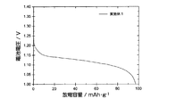
図2は、実施例1の開放式電池セルの5サイクル目の放電カーブを示す。図2に示される放電カーブより、LiFePO4粉末を炭素被覆した実施例1の開放式電池セルは、放電プラトー電圧が1.15〜1.10Vと平坦性に優れた放電特性を示した。負極材料の重量あたりの放電容量は、5サイクル目で94.7mAh/gであった。 FIG. 2 shows a discharge curve of the fifth cycle of the open battery cell of Example 1. From the discharge curve shown in FIG. 2, the open battery cell of Example 1 in which LiFePO 4 powder was coated with carbon showed a discharge plateau voltage of 1.15 to 1.10 V and excellent discharge characteristics. The discharge capacity per weight of the negative electrode material was 94.7 mAh / g at the fifth cycle.
図3は、実施例1及び参考例1の開放式電池セルの、10サイクル目までの放電容量の変化を示す。参考例1の開放式電池セルは、初期サイクルにおいて20〜30mAh/gの放電容量を示すが、速やかに放電容量の低下が起こり、3サイクル目以降では放電容量がほぼ0となった。一方、実施例1の開放式電池セルは、4サイクル目で放電容量は、ほぼ最大値である94mAh/gに達し、10サイクル目においても放電容量は91mAh/gを維持していた。 FIG. 3 shows the change in discharge capacity of the open battery cells of Example 1 and Reference Example 1 up to the 10th cycle. The open-type battery cell of Reference Example 1 exhibited a discharge capacity of 20 to 30 mAh / g in the initial cycle, but the discharge capacity rapidly decreased, and the discharge capacity became almost zero after the third cycle. On the other hand, in the open battery cell of Example 1, the discharge capacity reached a maximum value of 94 mAh / g at the fourth cycle, and the discharge capacity was maintained at 91 mAh / g even at the tenth cycle.
炭素被覆を施さないLiFePO4は、導電性が低いことが知られており、例えばリチウムイオン電池等の電極材料に用いる際には、炭素被覆等の手法により導電性を付与することが必須である。本発明の蓄電デバイスにおいても、LiFePO4粉末を負極材料とする場合には、導電性物質を用いて被覆する等して、LiFePO4粉末に導電性を付与することが好ましいと考えられた。 LiFePO 4 not subjected to carbon coating is known to have low conductivity. For example, when used for an electrode material such as a lithium ion battery, it is essential to impart conductivity by a method such as carbon coating. . Also in the electricity storage device of the present invention, when LiFePO 4 powder was used as the negative electrode material, it was considered preferable to impart conductivity to the LiFePO 4 powder by coating with a conductive substance.
[比較例1]
正極として、水酸化ニッケル粉末に替えて水酸化ランタン粉末を使用する以外、すべて実施例1と同様にして開放式電池セルを作製した。実施例1と同様に開放式電池セルの充放電試験を行ったが、電池容量は示さなかった。
[Comparative Example 1]
An open battery cell was produced in the same manner as in Example 1 except that lanthanum hydroxide powder was used instead of nickel hydroxide powder as the positive electrode. A charge / discharge test was conducted on the open battery cell in the same manner as in Example 1, but the battery capacity was not shown.
実施例1で使用した水酸化ニッケル正極と比較すると、比較例1で使用した水酸化ランタン中のLaイオンは3価で安定であり、Niイオン(2+⇔3+)のように、酸化還元を起こさない。このことが、比較例1の開放式電池セルが電池容量を示さなかった原因であると考えられた。すなわち、本発明で使用する複合、正極を構成する水酸化物は、例えばNiのように、容易に酸化還元を起こす遷移金属元素であることが好ましいと考えられた。 Compared with the nickel hydroxide positive electrode used in Example 1, La ions in the lanthanum hydroxide used in Comparative Example 1 are trivalent and stable, and cause redox like Ni ions (2 + 23 +). Absent. This was considered to be the reason why the open battery cell of Comparative Example 1 did not show battery capacity. That is, it was considered that the composite and the hydroxide constituting the positive electrode used in the present invention is preferably a transition metal element that easily undergoes redox, such as Ni.
[比較例2]
電解液として、7mol/lのKOH水溶液の替わりに3mol/lのK2CO3水溶液を使用する以外、すべて実施例1と同様にして開放式電池セルを作製した。実施例1と同様に開放式電池セルの充放電試験を行ったが、電池容量は示さなかった。
[Comparative Example 2]
An open battery cell was produced in the same manner as in Example 1 except that 3 mol / l K 2 CO 3 aqueous solution was used instead of 7 mol / l KOH aqueous solution as the electrolytic solution. A charge / discharge test was conducted on the open battery cell in the same manner as in Example 1, but the battery capacity was not shown.
[比較例3]
電解液として、7mol/lのKOH水溶液の替わりに4mol/lのK2B4O7水溶液を使用する以外、すべて実施例1と同様にして開放式電池セルを作製した。実施例1と同様に開放式電池セルの充放電試験を行ったが、電池容量は示さなかった。
[Comparative Example 3]
An open battery cell was produced in the same manner as in Example 1 except that a 4 mol / l K 2 B 4 O 7 aqueous solution was used instead of the 7 mol / l KOH aqueous solution as the electrolytic solution. A charge / discharge test was conducted on the open battery cell in the same manner as in Example 1, but the battery capacity was not shown.
実施例1で使用した水酸化カリウム電解液と比較すると、比較例2及び比較例3で使用した炭酸カリウム及びホウ酸カリウム水溶液中では、水酸化物イオンの濃度が低く、負極に対し十分にプロトンを供給できない。このことが、比較例2及び比較例3の開放式電池セルが電池容量を示さなかった原因であると考えられた。すなわち、本発明で使用する電解質は、十分な水酸化物イオンを含んでいる必要があり、アルカリ金属の水酸化物の水溶液であることが好ましいと考えられた。 Compared with the potassium hydroxide electrolyte used in Example 1, in the potassium carbonate and potassium borate aqueous solutions used in Comparative Example 2 and Comparative Example 3, the concentration of hydroxide ions is low, and the protons are sufficiently protonated with respect to the negative electrode. Can not supply. This was considered to be the reason why the open type battery cells of Comparative Example 2 and Comparative Example 3 did not show battery capacity. That is, the electrolyte used in the present invention needs to contain sufficient hydroxide ions, and it was considered preferable that the electrolyte be an aqueous solution of an alkali metal hydroxide.
[実施例2]
(負極の作製)
負極化合物であるLiCoO2粉末(日本化学工業製)と、導電性物質であるケッチェンブラックと、バインダであるSEBSとを、90:5:5の重量比で混合し、適量のキシレンを加えてスラリーを作製した。このスラリーを発泡状ニッケル(セルメット#8、住友電工製)に充填し、80℃で乾燥させた。圧延成型した後、端子接続用のNiリードを発泡状ニッケルに溶接して負極とした。負極の大きさは25mm角であり、充填したLiCoO2粉末の量は600mg(乾燥重量)であった。
[Example 2]
(Preparation of negative electrode)
LiCoO 2 powder (manufactured by Nippon Kagaku Kogyo Co., Ltd.) as a negative electrode compound, ketjen black as a conductive material, and SEBS as a binder are mixed at a weight ratio of 90: 5: 5, and an appropriate amount of xylene is added. A slurry was prepared. This slurry was filled in foamed nickel (
(正極の作製)
実施例1と同様にして、正極を作製した。
(Preparation of positive electrode)
In the same manner as in Example 1, a positive electrode was produced.
(二次電池の作製)
上記負極及び正極を用いて、実施例1と同様にして開放式電池セルを作製した。
(Production of secondary battery)
Using the negative electrode and the positive electrode, an open battery cell was produced in the same manner as in Example 1.
作製した開放式電池セルの充放電試験は、25℃の恒温槽中で60mAの電流(負極活物質の重量当たり100mA/gに相当する)で4時間充電し、その後60mA(負極活物質の重量当たり100mA/gに相当する)の電流値で電池電圧が1.0Vになるまで放電させることにより、作製した開放式電池セルの充放電試験を行った。 The charge / discharge test of the prepared open-type battery cell was performed by charging in a constant temperature bath at 25 ° C. with a current of 60 mA (corresponding to 100 mA / g per weight of the negative electrode active material) for 4 hours, and then 60 mA (weight of the negative electrode active material). A charge / discharge test of the produced open-type battery cell was performed by discharging until the battery voltage reached 1.0 V at a current value of 100 mA / g).
図4は、実施例2の開放式電池セルの5サイクル目の充放電カーブを示す。図4では、1.25〜1.40V付近に充電に基づくプラトー電圧が観測され、充電末期には急峻な電圧上昇が観測された。LiFePO4を負極材料として用いた実施例1の開放式電池セルと同様に、充電末期には急峻な電圧上昇は、水の電気分解反応の過電圧が高いことに起因すると考えられ、フロート充電時の充電制御や副反応(水の電気分解反応)の抑制の観点から有利であると考えられた。 FIG. 4 shows a charge / discharge curve at the fifth cycle of the open battery cell of Example 2. In FIG. 4, a plateau voltage based on charging was observed in the vicinity of 1.25 to 1.40 V, and a steep voltage increase was observed at the end of charging. Similar to the open battery cell of Example 1 using LiFePO 4 as the negative electrode material, the steep voltage increase at the end of charging is considered to be caused by the high overvoltage of the water electrolysis reaction. This was considered advantageous from the viewpoint of charge control and suppression of side reactions (water electrolysis reaction).
放電電圧は、放電深度にしたがって1.25Vから1.1Vまで単調に減少したため、プラトー性には劣るものの、電池電圧から放電深度が容易に類推できる利点があった。 Since the discharge voltage monotonously decreased from 1.25 V to 1.1 V according to the depth of discharge, the plateau was inferior, but there was an advantage that the depth of discharge could be easily inferred from the battery voltage.
図5は、実施例2の開放式電池セルの、10サイクル目までの放電容量の変化を示す。5サイクル目で放容量は、ほぼ最大値である130mAh/gに達し、10サイクル目においても放電容量は約90%の116mAh/gを維持していた。 FIG. 5 shows the change in discharge capacity of the open battery cell of Example 2 up to the 10th cycle. In the fifth cycle, the discharge capacity reached a maximum value of 130 mAh / g, and in the tenth cycle, the discharge capacity was maintained at about 90% of 116 mAh / g.
実施例2で負極化合物として使用したLiCoO2粉末は、コバルトイオンによる電子伝導性を有している。このため、実施例1で負極化合物として使用したLiFePO4粉末と異なり、特段の導電化処理を行わなくとも、二次電池の負極材料として使用し得たものと類推された。 The LiCoO 2 powder used as the negative electrode compound in Example 2 has electronic conductivity due to cobalt ions. For this reason, unlike the LiFePO 4 powder used as the negative electrode compound in Example 1, it was inferred that it could be used as the negative electrode material of the secondary battery without performing a special conductive treatment.
[比較例4]
LiCoO2粉末の替わりにLi2ZrO3粉末(高純度化学研究所製)を使用する以外、すべて実施例2と同様にして負極を作製した。この負極を用いて、実施例2と同様にして開放式電池セルを作製した。実施例2と同様に開放式電池セルの充放電試験を行ったが、電池容量は示さなかった。
[Comparative Example 4]
A negative electrode was produced in the same manner as in Example 2 except that Li 2 ZrO 3 powder (manufactured by High Purity Chemical Laboratory) was used instead of LiCoO 2 powder. Using this negative electrode, an open battery cell was produced in the same manner as in Example 2. The charge / discharge test of the open battery cell was performed in the same manner as in Example 2, but the battery capacity was not shown.
実施例1及び実施例2で使用した負極化合物と比較すると、比較例4で使用したLi2ZrO3中のZrイオンは4価で安定であり、Feイオン(2+⇔3+)又はCoイオン(2+⇔3+⇔4+)のように、酸化還元を起こしにくい。このことが、参考例2の開放式電池セルが電池容量を示さなかった原因であると考えられた。すなわち、本発明で使用する負極化合物を構成する遷移金属元素は、Fe又はCoのように、容易に酸化還元を起こす遷移金属元素であることが好ましいと考えられた。 Compared with the negative electrode compounds used in Example 1 and Example 2, the Zr ions in Li 2 ZrO 3 used in Comparative Example 4 are tetravalent and stable, and are Fe ions (2 + ⇔3 +) or Co ions (2+ Like (⇔3 + ⇔4 +), it is difficult to cause redox. This was considered to be the reason why the open type battery cell of Reference Example 2 did not show the battery capacity. That is, it was considered that the transition metal element constituting the negative electrode compound used in the present invention is preferably a transition metal element that easily undergoes redox, such as Fe or Co.
[実施例3]
(負極の作製)
負極化合物であるLi4Ti5O12粉末(高純度化学製)と、導電性物質である金属ニッケル粉末(<1μm、高純度化学製)とを、5:95の重量比で混合し、全圧5tで加圧成型して、φ10mmのペレットを作製した。このペレットを60メッシュのニッケルメッシュで挟み、ニッケルメッシュの周囲をスポット溶接してペレットを固定した。次いで、ニッケル板を該ニッケルメッシュに溶接して負極の試験電極(作用極)を作製した。
[Example 3]
(Preparation of negative electrode)
Li 4 Ti 5 O 12 powder (manufactured by high-purity chemical), which is a negative electrode compound, and metal nickel powder (<1 μm, manufactured by high-purity chemical), which is a conductive substance, are mixed at a weight ratio of 5:95. It was pressure molded at a pressure of 5 t to produce a 10 mm pellet. The pellet was sandwiched between 60 mesh nickel meshes, and the pellets were fixed by spot welding around the nickel meshes. Next, a nickel plate was welded to the nickel mesh to produce a negative electrode test electrode (working electrode).
発泡ニッケル電極を対極、酸化水銀(Hg/HgO)電極を参照極として、図6に示すH字型試験セルを作製した。これら電極を浸漬させる電解液としては、6M−KOH水溶液を使用した。このH字型試験セルについて、25℃でサイクリックボルタンメトリー測定を行った。電位走査速度は、10mVs−1とした。 An H-shaped test cell shown in FIG. 6 was prepared using a foamed nickel electrode as a counter electrode and a mercury oxide (Hg / HgO) electrode as a reference electrode. A 6M-KOH aqueous solution was used as an electrolytic solution for immersing these electrodes. The H-shaped test cell was subjected to cyclic voltammetry measurement at 25 ° C. The potential scanning speed was 10 mVs- 1 .
図7は、実施例3のH字型試験セルのサイクリックボルタモグラムを示す。図7では、−0.8〜―0.6Vにわたって酸化ピークが認められ、チタン酸リチウムが放電可能な材料であることが確認された。 FIG. 7 shows a cyclic voltammogram of the H-shaped test cell of Example 3. In FIG. 7, an oxidation peak was observed over −0.8 to −0.6 V, and it was confirmed that lithium titanate is a dischargeable material.
H字型試験セルについて、負極活物質の重量当たり100mA/gの電流で4時間充電し、その後負極活物質の重量当たり100mA/gの電流で酸化水銀参照極に対し−0.3Vになるまで放電させることにより、作製したH字型試験セルの充放電試験を行った。 The H-shaped test cell is charged for 4 hours at a current of 100 mA / g per weight of the negative electrode active material, and then is -0.3 V with respect to the mercury oxide reference electrode at a current of 100 mA / g per weight of the negative electrode active material. A charge / discharge test of the produced H-shaped test cell was performed by discharging.
[比較例5]
Li4Ti5O12粉末を使用せず、金属ニッケル粉末のみ加圧成形してペレットを作製する以外、実施例3と同様にH字型試験セルを作製した。また、実施例3と同様に作製したH字型試験セルの充放電試験を行った。
[Comparative Example 5]
An H-shaped test cell was prepared in the same manner as in Example 3 except that a pellet was prepared by pressure forming only metallic nickel powder without using Li 4 Ti 5 O 12 powder. Moreover, the charge / discharge test of the H-shaped test cell produced similarly to Example 3 was done.
図8は、実施例3及び比較例5のH字型試験セルの60サイクル目の充放電カーブを示す。実線で示した実施例3のH字型試験セルでは−0.8〜−0.95V付近に充電に基づくプラトー電圧が観測され、充電末期の急峻な電圧上昇は観測されなかった。また、−0.6〜−0.8V付近に放電に基づくプラトー電圧が観測された。 FIG. 8 shows charge / discharge curves at the 60th cycle of the H-shaped test cells of Example 3 and Comparative Example 5. In the H-shaped test cell of Example 3 indicated by the solid line, a plateau voltage based on charging was observed in the vicinity of −0.8 to −0.95 V, and a sharp voltage increase at the end of charging was not observed. In addition, a plateau voltage based on discharge was observed in the vicinity of -0.6 to -0.8 V.
一方、比較例5のH字型試験セルでは、実施例3と同様の充放電特性は示されなかった。このことから、実施例3のH字型試験セルの充放電特性は、負極化合物であるLi4Ti5O12によるものと考察された。 On the other hand, in the H-shaped test cell of Comparative Example 5, the charge / discharge characteristics similar to those of Example 3 were not shown. From this, it was considered that the charge / discharge characteristics of the H-shaped test cell of Example 3 were due to Li 4 Ti 5 O 12 which is a negative electrode compound.
本発明の蓄電デバイスは、水素吸蔵合金の替わりに負極化合物を負極材料として使用し、挿入種を水素イオンとすることにより、耐酸化性及び充放電特性に優れる。また、資源の安定供給の問題も克服できる。本発明の蓄電デバイスは、電池分野において有用である。 The electricity storage device of the present invention is excellent in oxidation resistance and charge / discharge characteristics by using a negative electrode compound as a negative electrode material instead of a hydrogen storage alloy and using insertion ions as hydrogen ions. In addition, the problem of stable supply of resources can be overcome. The electricity storage device of the present invention is useful in the battery field.
1:発泡ニッケル電極(対極)
2:試験電極(作用極)
3:酸化水銀電極(参照極)
4:6mol/lKOH水溶液
5:H字型試験セル
1: Foamed nickel electrode (counter electrode)
2: Test electrode (working electrode)
3: Mercury oxide electrode (reference electrode)
4: 6 mol / l KOH aqueous solution 5: H-shaped test cell
Claims (8)
(2)Niの水酸化物又はオキシ水酸化物を集電体に被着して形成した正極と、
(3)アルカリ水溶液を有する電解質と、
を具備する蓄電デバイス。 (1) a negative electrode formed by depositing LiFePO 4 as a negative electrode compound on a current collector;
(2) a positive electrode formed by depositing a hydroxide or oxyhydroxide of Ni on a current collector;
(3) an electrolyte having an alkaline aqueous solution;
An electricity storage device comprising:
(2)Niの水酸化物又はオキシ水酸化物を集電体に被着して形成した正極と、
(3)アルカリ水溶液を有する電解質と、
を具備する蓄電デバイス。 (1) a negative electrode formed by depositing Li 4 Ti 5 O 12 as a negative electrode compound on a current collector;
(2) a positive electrode formed by depositing a hydroxide or oxyhydroxide of Ni on a current collector;
(3) an electrolyte having an alkaline aqueous solution;
An electricity storage device comprising:
(2)Niの水酸化物又はオキシ水酸化物を集電体に被着して形成した正極と、
(3)アルカリ水溶液を有する電解質と、
を具備する蓄電デバイス。 (1) a negative electrode formed by depositing LiCoO 2 as a negative electrode compound on a current collector;
(2) a positive electrode formed by depositing a hydroxide or oxyhydroxide of Ni on a current collector;
(3) an electrolyte having an alkaline aqueous solution;
An electricity storage device comprising:
Priority Applications (1)
| Application Number | Priority Date | Filing Date | Title |
|---|---|---|---|
| JP2010123393A JP5557385B2 (en) | 2010-05-28 | 2010-05-28 | Energy storage device with proton as insertion species |
Applications Claiming Priority (1)
| Application Number | Priority Date | Filing Date | Title |
|---|---|---|---|
| JP2010123393A JP5557385B2 (en) | 2010-05-28 | 2010-05-28 | Energy storage device with proton as insertion species |
Publications (3)
| Publication Number | Publication Date |
|---|---|
| JP2011249238A JP2011249238A (en) | 2011-12-08 |
| JP2011249238A5 JP2011249238A5 (en) | 2013-07-18 |
| JP5557385B2 true JP5557385B2 (en) | 2014-07-23 |
Family
ID=45414239
Family Applications (1)
| Application Number | Title | Priority Date | Filing Date |
|---|---|---|---|
| JP2010123393A Active JP5557385B2 (en) | 2010-05-28 | 2010-05-28 | Energy storage device with proton as insertion species |
Country Status (1)
| Country | Link |
|---|---|
| JP (1) | JP5557385B2 (en) |
Families Citing this family (3)
| Publication number | Priority date | Publication date | Assignee | Title |
|---|---|---|---|---|
| JP6321287B2 (en) * | 2016-02-01 | 2018-05-09 | 株式会社東芝 | Secondary battery, assembled battery, battery pack, and vehicle |
| US10727540B2 (en) | 2016-02-01 | 2020-07-28 | Kabushiki Kaisha Toshiba | Secondary battery, battery module, battery pack and vehicle |
| JPWO2023026972A1 (en) * | 2021-08-25 | 2023-03-02 |
Family Cites Families (5)
| Publication number | Priority date | Publication date | Assignee | Title |
|---|---|---|---|---|
| JP3475652B2 (en) * | 1995-07-31 | 2003-12-08 | 松下電器産業株式会社 | Negative electrode for alkaline storage battery and battery using the same |
| JP4929580B2 (en) * | 2003-10-30 | 2012-05-09 | 株式会社Gsユアサ | Lithium ion secondary battery |
| JP2005135775A (en) * | 2003-10-30 | 2005-05-26 | Yuasa Corp | Lithium ion secondary battery |
| JP2005276486A (en) * | 2004-03-23 | 2005-10-06 | Nissan Motor Co Ltd | Laminated battery, battery pack, and vehicle |
| KR101041932B1 (en) * | 2008-10-15 | 2011-06-16 | 한국과학기술연구원 | Electrode for secondary battery and the fabrication method thereof, and secondary battery using the same |
-
2010
- 2010-05-28 JP JP2010123393A patent/JP5557385B2/en active Active
Also Published As
| Publication number | Publication date |
|---|---|
| JP2011249238A (en) | 2011-12-08 |
Similar Documents
| Publication | Publication Date | Title |
|---|---|---|
| KR102166391B1 (en) | Secondary zinc-manganese dioxide batteries for high power applications | |
| KR101758967B1 (en) | Battery | |
| US11482701B2 (en) | Cycling protocol for alkaline batteries | |
| JP5927372B2 (en) | Alkaline secondary battery and method for producing alkaline secondary battery | |
| JP5719175B2 (en) | Pasted nickel hydroxide electrode for rechargeable nickel-zinc battery | |
| WO2014032594A1 (en) | Battery | |
| JP2002110154A (en) | Manufacturing method of positive pole active material for alkaline battery | |
| KR20090013831A (en) | Lithium secondary battery | |
| JP2007103298A (en) | Positive electrode active material, its manufacturing method, and aqueous lithium secondary battery | |
| WO2007004703A1 (en) | Nickel-hydrogen battery | |
| WO2021046151A1 (en) | Aqueous electrochemical cells using polymer gel electrolytes | |
| US10079385B2 (en) | Positive electrode for alkaline storage battery and alkaline storage battery using the same | |
| CN113314770B (en) | Alkaline secondary battery and preparation method thereof | |
| JP5557385B2 (en) | Energy storage device with proton as insertion species | |
| WO2005041343A1 (en) | Electrochemical energy storage device | |
| JP3931518B2 (en) | Nickel-hydrogen secondary battery | |
| WO2020086835A1 (en) | A protective barrier layer for alkaline batteries | |
| JP4474722B2 (en) | Alkaline storage battery and positive electrode for alkaline storage battery used therefor | |
| JP2926732B2 (en) | Alkaline secondary battery | |
| CN102208648A (en) | Secondary battery electrode and secondary battery | |
| US20220384856A1 (en) | Mitigating the zincate effect in energy dense manganese dioxide electrodes | |
| JP2011018493A (en) | Nickel hydrogen secondary battery | |
| JP6955686B2 (en) | Power storage element | |
| US20190097213A1 (en) | Processes and compositions to improve high-temperature performance of nimh batteries | |
| CN116783734A (en) | Positive electrode active material for proton-conducting secondary battery and proton-conducting secondary battery provided with same |
Legal Events
| Date | Code | Title | Description |
|---|---|---|---|
| A521 | Request for written amendment filed |
Free format text: JAPANESE INTERMEDIATE CODE: A523 Effective date: 20130517 |
|
| A621 | Written request for application examination |
Free format text: JAPANESE INTERMEDIATE CODE: A621 Effective date: 20130517 |
|
| A521 | Request for written amendment filed |
Free format text: JAPANESE INTERMEDIATE CODE: A523 Effective date: 20130501 |
|
| A977 | Report on retrieval |
Free format text: JAPANESE INTERMEDIATE CODE: A971007 Effective date: 20140212 |
|
| A131 | Notification of reasons for refusal |
Free format text: JAPANESE INTERMEDIATE CODE: A131 Effective date: 20140304 |
|
| A521 | Request for written amendment filed |
Free format text: JAPANESE INTERMEDIATE CODE: A523 Effective date: 20140417 |
|
| A521 | Request for written amendment filed |
Free format text: JAPANESE INTERMEDIATE CODE: A523 Effective date: 20140430 |
|
| TRDD | Decision of grant or rejection written | ||
| A01 | Written decision to grant a patent or to grant a registration (utility model) |
Free format text: JAPANESE INTERMEDIATE CODE: A01 Effective date: 20140520 |
|
| A61 | First payment of annual fees (during grant procedure) |
Free format text: JAPANESE INTERMEDIATE CODE: A61 Effective date: 20140602 |
|
| R150 | Certificate of patent or registration of utility model |
Ref document number: 5557385 Country of ref document: JP Free format text: JAPANESE INTERMEDIATE CODE: R150 |
|
| S533 | Written request for registration of change of name |
Free format text: JAPANESE INTERMEDIATE CODE: R313533 |
|
| R350 | Written notification of registration of transfer |
Free format text: JAPANESE INTERMEDIATE CODE: R350 |
|
| R250 | Receipt of annual fees |
Free format text: JAPANESE INTERMEDIATE CODE: R250 |
|
| R250 | Receipt of annual fees |
Free format text: JAPANESE INTERMEDIATE CODE: R250 |
|
| R250 | Receipt of annual fees |
Free format text: JAPANESE INTERMEDIATE CODE: R250 |
|
| R250 | Receipt of annual fees |
Free format text: JAPANESE INTERMEDIATE CODE: R250 |
|
| R250 | Receipt of annual fees |
Free format text: JAPANESE INTERMEDIATE CODE: R250 |
|
| S111 | Request for change of ownership or part of ownership |
Free format text: JAPANESE INTERMEDIATE CODE: R313115 |
|
| R350 | Written notification of registration of transfer |
Free format text: JAPANESE INTERMEDIATE CODE: R350 |
|
| R250 | Receipt of annual fees |
Free format text: JAPANESE INTERMEDIATE CODE: R250 |
|
| R250 | Receipt of annual fees |
Free format text: JAPANESE INTERMEDIATE CODE: R250 |
|
| R250 | Receipt of annual fees |
Free format text: JAPANESE INTERMEDIATE CODE: R250 |