JP5557021B2 - Rotation angle detector - Google Patents
Rotation angle detector Download PDFInfo
- Publication number
- JP5557021B2 JP5557021B2 JP2010166122A JP2010166122A JP5557021B2 JP 5557021 B2 JP5557021 B2 JP 5557021B2 JP 2010166122 A JP2010166122 A JP 2010166122A JP 2010166122 A JP2010166122 A JP 2010166122A JP 5557021 B2 JP5557021 B2 JP 5557021B2
- Authority
- JP
- Japan
- Prior art keywords
- rotation angle
- sin
- sine wave
- rotation
- rotor
- Prior art date
- Legal status (The legal status is an assumption and is not a legal conclusion. Google has not performed a legal analysis and makes no representation as to the accuracy of the status listed.)
- Expired - Fee Related
Links
Images
Classifications
-
- G—PHYSICS
- G01—MEASURING; TESTING
- G01D—MEASURING NOT SPECIALLY ADAPTED FOR A SPECIFIC VARIABLE; ARRANGEMENTS FOR MEASURING TWO OR MORE VARIABLES NOT COVERED IN A SINGLE OTHER SUBCLASS; TARIFF METERING APPARATUS; MEASURING OR TESTING NOT OTHERWISE PROVIDED FOR
- G01D5/00—Mechanical means for transferring the output of a sensing member; Means for converting the output of a sensing member to another variable where the form or nature of the sensing member does not constrain the means for converting; Transducers not specially adapted for a specific variable
- G01D5/12—Mechanical means for transferring the output of a sensing member; Means for converting the output of a sensing member to another variable where the form or nature of the sensing member does not constrain the means for converting; Transducers not specially adapted for a specific variable using electric or magnetic means
- G01D5/244—Mechanical means for transferring the output of a sensing member; Means for converting the output of a sensing member to another variable where the form or nature of the sensing member does not constrain the means for converting; Transducers not specially adapted for a specific variable using electric or magnetic means influencing characteristics of pulses or pulse trains; generating pulses or pulse trains
- G01D5/24471—Error correction
- G01D5/24476—Signal processing
Description
この発明は、回転体の回転角を検出する回転角検出装置に関する。 The present invention relates to a rotation angle detection device that detects a rotation angle of a rotating body.
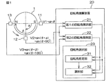
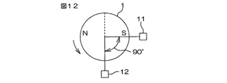
電動パワーステアリング装置などに使用されるブラシレスモータは、ロータの回転角度に合わせてステータ巻線に電流を通電することによって制御される。そこで、たとえば、図12に示す回転角検出装置が知られている。回転角検出装置は、2つの磁極N,Sを有する磁石を含むロータ1と、ロータ1の回転中心軸を中心として90°の角度間隔をおいて配置された2つの磁気センサ11,12とを含む。各磁気センサ11,12は、互いに90°の位相差を有する正弦波信号を出力する。回転角検出装置は、これらの2つの正弦波信号に基づいてロータ1の回転角を検出する。
A brushless motor used in an electric power steering apparatus or the like is controlled by passing a current through the stator winding in accordance with the rotation angle of the rotor. Thus, for example, a rotation angle detection device shown in FIG. 12 is known. The rotation angle detection device includes a
図12に矢印で示す方向をロータ1の正方向の回転方向とする。そして、ロータ1が正方向に回転されるとロータ1の回転角が大きくなり、ロータ1が逆方向に回転されると、ロータ1の回転角が小さくなるものとする。ロータ1の回転角θに対して、一方の磁気センサ11からV1=A1・sinθの出力信号V1が出力されるとすると、他方の磁気センサ12からは、V2=A2・sin(θ+90°)=A2・cosθの出力信号V2が出力される。A1,A2は、それぞれ振幅を表している。
The direction indicated by the arrow in FIG. 12 is defined as the positive direction of rotation of the
これらの振幅A1,A2が互いに等しい値Aであるとみなすか、あるいは両振幅が所定の規定値Aとなるように両信号S1,S2を正規化したとすると、一方の出力信号V1は、V1=A・sinθと表され、他方の出力信号V2は、V2=A・cosθと表される。さらに、A=1とすると、一方の出力信号V1は、V1=sinθで表され、他方の出力信号V2は、V2=cosθで表される。そこで、説明を簡単にするために、磁気センサ11,12の出力信号V1,V2を、V1=sinθ、V2=sin(θ+90°)=cosθで表すことにする。
If these amplitudes A1 and A2 are considered to be equal to each other, or if both signals S1 and S2 are normalized so that both amplitudes have a predetermined specified value A, one output signal V1 is V1. = A · sin θ, and the other output signal V2 is expressed as V2 = A · cos θ. Further, if A = 1, one output signal V1 is represented by V1 = sin θ, and the other output signal V2 is represented by V2 = cos θ. Therefore, to simplify the explanation, the output signals V1 and V2 of the
ロータの回転角θは、両出力信号V1,V2を用いて、たとえば、次式(1)に基づいて求めることができる。
θ=tan−1(sinθ/cosθ)
=tan−1(sinθ/sin(θ+90°))
=tan−1(V1/V2)…(1)
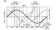
図2は、ロータ1の回転角θに対する、磁気センサ11,12の出力信号V1(=sinθ),V2(=sin(θ+90°))および前記式(1)の右辺におけるsinθ/sin(θ+90°)の変化を示している。
The rotation angle θ of the rotor can be obtained based on, for example, the following equation (1) using both output signals V1 and V2.
θ = tan −1 (sinθ / cosθ)
= Tan −1 (sin θ / sin (θ + 90 °))
= Tan -1 (V1 / V2) (1)
FIG. 2 shows the output signals V1 (= sin θ) and V2 (= sin (θ + 90 °)) of the
前述したような従来の回転角検出装置においては、前記式(1)に基づいて、ロータ1の回転角θを演算する際、sinθ/cosθの分母になるcosθが零付近になると、演算誤差が大きくなる。したがって、図2に斜線部分で示すように、ロータ角度が90°付近の範囲内または270°付近の範囲内にある場合には、cosθ(=sin(θ+90°))の絶対値が小さくなるため、tan−1(sinθ/cosθ)に基づいて演算される回転角θの誤差が大きくなる。
In the conventional rotation angle detection device as described above, when the rotation angle θ of the
そこで、この発明の目的は、検出精度を高めることができる回転角検出装置を提供することである。
また、前述したような従来の回転角検出装置においては、磁気センサの出力信号に含まれるノイズの影響によって検出誤差が発生するおそれがある。そこで、このような検出誤差を低減させるために、磁気センサの出力信号に基づいて検出される回転角を時間方向に平均化することによって、最終的な回転角を求めることが考えられる。しかし、このようにすると、ロータが高速回転している場合には、回転角検出の応答性が悪くなる。
Accordingly, an object of the present invention is to provide a rotation angle detection device that can improve detection accuracy.
Further, in the conventional rotation angle detection device as described above, there is a possibility that a detection error may occur due to the influence of noise included in the output signal of the magnetic sensor. Therefore, in order to reduce such a detection error, it is conceivable to obtain the final rotation angle by averaging the rotation angle detected based on the output signal of the magnetic sensor in the time direction. However, if this is done, when the rotor rotates at a high speed, the response of rotation angle detection becomes poor.
そこで、この発明の目的は、高い応答性を維持しつつ、ノイズの影響による検出誤差を低減できる回転角検出装置を提供することである。 Accordingly, an object of the present invention is to provide a rotation angle detection device capable of reducing detection errors due to the influence of noise while maintaining high responsiveness.
請求項1記載の発明は、回転体(1)の回転に応じて、互いに位相差を有する第1、第2および第3の正弦波信号をそれぞれ出力する第1、第2および第3のセンサ(61〜63)を含み、これらのセンサの出力信号に基づいて前記回転体の回転角を検出する回転角検出装置(70)であって、前記第1の正弦波信号と前記第2の正弦波信号とに基づいて、前記回転体の回転角に相当する第1の回転角を演算する第1回転角演算手段(71)と、前記第1の正弦波信号と前記第3の正弦波信号とに基づいて、前記回転体の回転角に相当する第2の回転角を演算する第2回転角演算手段(72)と、前記第2の正弦波信号と前記第3の正弦波信号とに基づいて、前記回転体の回転角に相当する第3の回転角を演算する第3回転角演算手段(73)と、前記第1、第2および第3の回転角に基づいて、最終的な回転角を演算する最終回転角演算手段(74)とを含み、前記第1のセンサは、前記回転体の回転角θに対して、V1=sinθで表される第1の正弦波信号V1を出力するものであり、前記第2のセンサは、前記回転体の回転角θに対して、前記第1および第2の正弦波信号の位相差αを用いてV2=sin(θ+α)で表される第2の正弦波信号V2を出力するものであり、前記第3のセンサは、前記回転体の回転角θに対して、前記第1および第3の正弦波信号の位相差βを用いてV3=sin(θ+β)で表される第3の正弦波信号V3を出力するものであり、前記第1回転角演算手段は、次式(i)により、第1の回転角θ1を求めるものであり、前記第2回転角演算手段は、次式(ii)により、第2の回転角θ2を求めるものであり、前記第3回転角演算手段は、次式(iii)により、第3の回転角θ3を求めるものである、回転角検出装置である。なお、括弧内の英数字は、後述の実施形態における対応構成要素等を表すが、むろん、この発明の範囲は当該実施形態に限定されない。以下、この項において同じ。

この構成では、第1の正弦波信号V1と前記第2の正弦波信号V2とに基づいて、式(i)により、回転体の回転角に相当する第1の回転角θ1が演算される。また、第1の正弦波信号V1と第3の正弦波信号V3とに基づいて、式(ii)により、回転体の回転角に相当する第2の回転角θ2が演算される。また、第2の正弦波信号V2と第3の正弦波信号V3とに基づいて、式(iii)により、回転体の回転角に相当する第3の回転角θ3が演算される。そして、第1、第2および第3の回転角θ1,θ2,θ3に基づいて、最終的な回転角が演算される。具体的には、たとえば、第1、第2および第3の回転角θ1,θ2,θ3の平均値または中央値を、最終的な回転角として演算することができる。また、第1、第2および第3の回転角θ1,θ2,θ3のうち、最も外れているものを除外し、他の2つの平均値を、最終的な回転角として演算することもできる。 In this configuration, based on the first sine wave signal V1 and the second sine wave signal V2 , the first rotation angle θ1 corresponding to the rotation angle of the rotating body is calculated by the equation (i) . Further, based on the first sine wave signal V1 and the third sine wave signal V3 , the second rotation angle θ2 corresponding to the rotation angle of the rotating body is calculated by the equation (ii) . Further, based on the second sine wave signal V2 and the third sine wave signal V3 , the third rotation angle θ3 corresponding to the rotation angle of the rotating body is calculated by the equation (iii) . Then, the final rotation angle is calculated based on the first, second, and third rotation angles θ1, θ2, and θ3 . Specifically, for example, the average value or median value of the first, second, and third rotation angles θ1, θ2, and θ3 can be calculated as the final rotation angle. In addition, the first, second, and third rotation angles θ1, θ2, and θ3 that are most distant can be excluded, and the other two average values can be calculated as the final rotation angle.
この構成によれば、第1、第2および第3の回転角θ1,θ2,θ3に基づいて、最終的な回転角が演算されるので、センサの出力信号に含まれるノイズの影響による検出誤差を低減できる。また、最終的な回転角は、同時刻に発生したセンサ出力信号から演算された第1、第2および第3の回転角θ1,θ2,θ3に基づいて演算されるので、回転角検出に時間遅れが発生しない。このため回転体の回転速度が大きい場合でも、高い応答性を実現できる。つまり、この構成によれば、高い応答性を維持しつつ、ノイズの影響による検出誤差を低減できる。 According to this configuration, since the final rotation angle is calculated based on the first, second, and third rotation angles θ1, θ2, and θ3 , a detection error due to the influence of noise included in the output signal of the sensor. Can be reduced. Further, since the final rotation angle is calculated based on the first, second and third rotation angles θ1, θ2 and θ3 calculated from the sensor output signal generated at the same time, it takes time to detect the rotation angle. There is no delay. For this reason, even when the rotational speed of the rotating body is high, high responsiveness can be realized. That is, according to this configuration, it is possible to reduce detection errors due to the influence of noise while maintaining high responsiveness.
また、この構成では、第1、第2および第3の回転角θ1,θ2,θ3を演算する場合に、同じセンサの出力信号を複数の回転角演算のために共用している。具体的には、第1の正弦波信号V1は、第1の回転角θ1および第2の回転角θ2の演算のために共用され、第2の正弦波信号V2は、第1の回転角θ1および第3の回転角θ3の演算のために共用され、第3の正弦波信号V3は、第2の回転角θ2および第3の回転角θ3の演算のために共用されている。このため、同じセンサの出力信号を複数の回転角演算のために共用しない場合に比べて、センサの個数が少なくて済むという利点がある。
請求項2記載の発明は、前記最終回転角演算手段は、前記第1、第2および第3の回転角の平均値、前記第1、第2および第3の回転角の中央値または前記第1、第2および第3の回転角のうちの中央値と、他の2つの回転角のうち、前記中央値との差が小さいものとの平均値を、最終的な回転角として演算するように構成されている、請求項1に記載の回転角検出装置である。
Further, in this configuration, when calculating the first, second and third rotation angles θ1, θ2, and θ3, the same sensor output signal is shared for a plurality of rotation angle calculations. Specifically, the first sine wave signal V1 is shared for the calculation of the first rotation angle θ1 and the second rotation angle θ2, and the second sine wave signal V2 is the first rotation angle θ1. The third sine wave signal V3 is shared for calculating the second rotation angle θ2 and the third rotation angle θ3. For this reason, there is an advantage that the number of sensors can be reduced as compared with the case where the output signals of the same sensor are not shared for calculation of a plurality of rotation angles.
According to a second aspect of the invention, before Symbol final rotation angle calculation means, the first, the average value of the second and third rotation angle, the first, the median of the second and third rotation angle or the The average value of the median value among the first, second, and third rotation angles and the difference between the median value of the other two rotation angles is calculated as the final rotation angle. It is a rotation angle detection apparatus of
以下では、この発明をブラシレスモータのロータの回転角を検出するための回転角検出装置に適用した場合の実施形態について、添付図面を参照して詳細に説明する。
図1は、この発明の第1の実施形態に係る回転角検出装置の構成を示す模式図である。
この回転角検出装置は、たとえば、電動パワーステアリング装置のブラシレスモータのロータの回転角を検出するために用いることができる。回転角検出装置は、たとえば、ブラシレスモータの回転に応じて回転する検出用ロータ1(以下、「ロータ1」という)を有している。ロータ1は、2つの磁極N,Sを有する磁石を含んでいる。以上の点は、後述する第2および第3の実施形態に係る回転角検出装置も同様である。
Hereinafter, an embodiment when the present invention is applied to a rotation angle detection device for detecting the rotation angle of a rotor of a brushless motor will be described in detail with reference to the accompanying drawings.
FIG. 1 is a schematic diagram showing a configuration of a rotation angle detection device according to the first embodiment of the present invention.
This rotation angle detection device can be used, for example, to detect the rotation angle of a rotor of a brushless motor of an electric power steering device. The rotation angle detection device has, for example, a detection rotor 1 (hereinafter referred to as “
ロータ1の周囲には、3つの磁気センサ11,12,13が、ロータ1の周方向に間隔をおいて配置されている。これら3つの磁気センサ11,12,13を、それぞれ第1の磁気センサ11、第2の磁気センサ12および第3の磁気センサ13という場合がある。磁気センサとしては、たとえば、ホール素子、磁気抵抗素子(MR素子)等、磁界の作用により電気的特性が変化する特性を有する素子を備えたものを用いることができる。
Around the
第1の磁気センサ11と第2の磁気センサ12とは、ロータ1の回転中心軸を中心として、αの角度間隔をおいて配置されている。第1の磁気センサ11と第3の磁気センサ13とは、ロータ1の回転中心軸を中心として、αより大きなβの角度間隔をおいて配置されている。この実施形態では、αは90°に設定され、βは180°に設定されている。したがって、この実施形態では、第2の磁気センサ12と第3の磁気センサ13との間の角度間隔は、90°となる。
The first
図1に矢印で示す方向をロータ1の正方向の回転方向とする。そして、ロータ1が正方向に回転されるとロータ1の回転角が大きくなり、ロータ1が逆方向に回転されると、ロータ1の回転角が小さくなるものとする。ロータ1の回転角θに対して、第1の磁気センサ11からV1=A1・sinθの出力信号V1が出力されるとすると、第2の磁気センサ12からは、V2=A2・sin(θ+α)=A2・sin(θ+90°)の出力信号V2が出力され、第3の磁気センサ13からは、V3=A3・sin(θ+β)=A3・sin(θ+180°)の出力信号V3が出力される。A1,A2,A3は、それぞれ振幅を表している。
The direction indicated by the arrow in FIG. 1 is defined as the positive rotation direction of the
これらの振幅A1,A2,A3が互いに等しい値Aであるとみなすか、あるいは各振幅が所定の規定値Aとなるように各信号V1,V2,V3を正規化したとすると、各信号V1,V2,V3は、それぞれ、A・sinθ,A・sin(θ+α)およびA・sin(θ+β)と表される。ここで、A=1とすると、各信号V1,V2,V3は、それぞれ、sinθ, sin(θ+α)およびsin(θ+β)と表される。そこで、以下の説明においては、説明を簡単にするために、各磁気センサ11,12,13の出力信号V1,V2,V3を、それぞれV1=sinθ,V2=sin(θ+α)=sin(θ+90°)およびV3=sin(θ+β)=sin(θ+180°)と表すことにする。
If these amplitudes A1, A2 and A3 are considered to be equal to each other, or if the signals V1, V2 and V3 are normalized so that the respective amplitudes become a predetermined specified value A, each signal V1, V2 and V3 are expressed as A · sin θ, A · sin (θ + α) and A · sin (θ + β), respectively. Here, when A = 1, the signals V1, V2, and V3 are expressed as sin θ, sin (θ + α), and sin (θ + β), respectively. Therefore, in the following description, for simplification of description, the output signals V1, V2, and V3 of the
各磁気センサ11,12,13の出力信号V1,V2,V3は、回転角演算装置20に入力される。回転角演算装置20は、各磁気センサ11,12,13の出力信号V1,V2,V3に基づいて、ロータ1の回転角θを演算する。回転角演算装置20は、たとえば、マイクロコンピュータから構成され、CPU(中央演算処理装置)およびメモリ(ROM,RAM等)を含んでいる。回転角演算装置20は、ROMに格納された所定のプログラムをCPUが実行することにより、複数の機能処理部として機能する。この複数の機能処理部は、第1の回転角演算部(第1回転角演算手段)21、第2の回転角演算部(第2回転角演算手段)22および回転角選択部(最終回転角演算手段)23を含む。
Output signals V1, V2, and V3 of the
第1の回転角演算部21は、第1の磁気センサ11の出力信号V1と、第2の磁気センサ12の出力信号V2とに基づいて、ロータ1の回転角に相当する第1の回転角θ1を演算する。この実施形態では、V1=sinθ,V2=sin(θ+90°)=cosθである。また、tanθは、tanθ=sinθ/cosθと表すことができる。そこで、第1の回転角演算部21は、次式(2)に基づいて、第1の回転角θ1を演算する。
The first rotation
第2の回転角演算部22は、第2の磁気センサ12の出力信号V2と、第3の磁気センサ13の出力信号V3とに基づいて、ロータ1の回転角に相当する第2の回転角θ2を演算する。この実施形態では、V2=sin(θ+90°),V3=sin(θ+180°)=cos(θ+90°)である。また、tan(θ+90°)は、tan(θ+90°)=sin(θ+90°)/cos(θ+90°)と表すことができる。そこで、第2の回転角演算部22は、次式(3)に基づいて、第2の回転角θ2を演算する。
The second rotation
回転角選択部23は、ロータ1の回転角推定値に応じて、第1の回転角θ1および第2の回転角θ2のうちのいずれか一方を、最終的な回転角θとして選択する。回転角選択部23による回転角選択の考え方について説明する。
図2は、ロータ1の回転角θに対する、磁気センサ11,12の出力信号V1(=sinθ),V2(=sin(θ+90°))および前記式(2)の右辺におけるsinθ/sin(θ+90°)の変化を示している。sinθ/sin(θ+90°)の分母のsin(θ+90°)の絶対値が小さい場合には、tan−1(sinθ/sin(θ+90°))の演算誤差が大きくなり、第1の回転角θ1の演算誤差が大きくなる。したがって、図2に斜線部分で示すように、ロータ1の回転角θが、90°付近の範囲(たとえば、90°±22.5°の範囲)および270°付近の範囲(たとえば、270°±22.5°の範囲)では、sin(θ+90°)の絶対値が小さくなるので、第1の回転角θ1の演算誤差が大きくなる。
The
FIG. 2 shows the output signals V1 (= sin θ) and V2 (= sin (θ + 90 °)) of the
図2において、sinθ/sin(θ+90°)を表す曲線のうち、鎖線の楕円で囲まれた部分は、sin(θ+90°)の絶対値が大きくなるために、tan−1(sinθ/sin(θ+90°))の演算誤差が小さくなる部分(演算精度が高くなる部分)を示している。
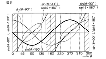
図3は、ロータ1の回転角θに対する、磁気センサ12,13の出力信号V2(=sin(θ+90°),V3(=sin(θ+180°))および前記式(3)の右辺におけるsin(θ+90°)/sin(θ+180°)の変化を示している。sin(θ+90°)/sin(θ+180°)の分母のsin(θ+180°)の絶対値が小さい場合には、tan−1{(sin(θ+90°)/sin(θ+180°)}の演算誤差が大きくなり、第2の回転角θ2の演算誤差が大きくなる。したがって、図3に斜線部分で示すように、ロータ1の回転角θが、0°付近の範囲(たとえば、0°〜22.5°の範囲)、180°付近の範囲(たとえば、180°±22.5°の範囲)および360°付近の範囲(たとえば、337.5〜360°の範囲)では、sin(θ+180°)の絶対値が小さくなるので、第2の回転角θ2の演算誤差が大きくなる。
In FIG. 2, in the curve representing sin θ / sin (θ + 90 °), the absolute value of sin (θ + 90 °) is increased in the portion surrounded by the ellipse of the chain line, so that tan −1 (sin θ / sin (θ + 90) °)) where the calculation error is small (the calculation accuracy is high).
FIG. 3 shows output signals V2 (= sin (θ + 90 °), V3 (= sin (θ + 180 °)) of the
図3において、sin(θ+90°)/sin(θ+180°)を表す曲線のうち、鎖線の楕円で囲まれた部分は、sin(θ+180°)の絶対値が大きくなるために、tan−1sin(θ+90°)/sin(θ+180°)の演算誤差が小さくなる部分(演算精度が高くなる部分)を示している。
図2および図3で説明したように、第1の回転角θ1と第2の回転角θ2とでは、演算誤差が大きくなる角度範囲が異なる。そこで、回転角選択部23は、たとえば、第1の回転角θ1と第2の回転角θ2とからロータ1の回転角を推定し、推定された回転角(回転角推定値)に応じて、第1の回転角θ1および第2の回転角θ2のうちから、演算誤差が小さい(演算精度が高い)と推定される方を、最終的な回転角θとして選択する。
In FIG. 3, in the curve representing sin (θ + 90 °) / sin (θ + 180 °), the portion surrounded by the ellipse of the chain line has a large absolute value of sin (θ + 180 °), so tan −1 sin ( A portion where the calculation error of θ + 90 °) / sin (θ + 180 °) is small (a portion where the calculation accuracy is high) is shown.
As described with reference to FIGS. 2 and 3, the first rotation angle θ 1 and the second rotation angle θ 2 have different angle ranges in which the calculation error increases. Therefore, for example, the rotation
具体的には、回転角選択部23は、回転角推定部31と、選択部32とを備えている。回転角推定部31は、たとえば、次式(4)に基づいて、第1の回転角θ1と第2の回転角θ2との平均を演算することにより、回転角推定値θEを求める。
θE=(θ1+θ2)/2 …(4)
選択部32は、回転角推定部31によって得られた回転角推定値θEを用い、次式(5)に示す条件式にしたがって、第1の回転角θ1および第2の回転角θ2のうちの一方を、最終的な回転角θとして選択する。
Specifically, the rotation
θ E = (θ 1 + θ 2 ) / 2 (4)
The
If 0°≦θE<45° then θ=θ1
If 45°≦θE<135° then θ=θ2
If 135°≦θE<225° then θ=θ1
If 225°≦θE<315° then θ=θ2
If 315°≦θE<360° then θ=θ1 …(5)
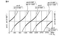
図4は、回転角推定値θEに対するsinθ/sin(θ+90°)の変化と、回転角推定値θEに対するsin(θ+90°)/sin(θ+180°)の変化とを示している。前述したように、tan−1{(sinθ°)/sin(θ+90°)}は、第1の回転角θ1を演算するために用いられ、tan−1{(sin(θ+90°)/sin(θ+180°)}は、第2の回転角θ2を演算するために用いられる。
If 0 ° ≦ θ E <45 ° then θ = θ 1
If 45 ° ≦ θ E <135 ° then θ = θ 2
If 135 ° ≦ θ E <225 ° then θ = θ 1
If 225 ° ≦ θ E <315 ° then θ = θ 2
If 315 ° ≦ θ E <360 ° then θ = θ 1 (5)
Figure 4 shows the change of sinθ / sin (θ + 90 ° ) with respect to the rotation angle estimated value theta E, and a change in sin (θ + 90 °) / sin (θ + 180 °) with respect to the rotation angle estimated value theta E. As described above, tan −1 {(sin θ °) / sin (θ + 90 °)} is used to calculate the first rotation angle θ 1 and tan −1 {(sin (θ + 90 °) / sin ( θ + 180 °)} is used to calculate the second rotation angle θ 2 .
図4においては、sinθ/sin(θ+90°)を表す曲線のうち、演算精度が高い部分(図2において楕円で囲まれた部分に相当する)が、その他の部分より太い線で示されている。同様に、sin(θ+90°)/sin(θ+180°)を表す曲線のうち、演算精度が高い部分(図3において楕円で囲まれた部分に相当する)が、その他の部分より太い線で示されている。前記式(5)で示された条件式にしたがって、第1の回転角θ1および第2の回転角θ2のうちから最終的な回転角θを選択する場合には、回転角推定値θEに対応する前記曲線の太線部分(演算精度の高い部分)を用いて演算された回転角が、最終的な回転角θとして選択されることになる。 In FIG. 4, a portion with high calculation accuracy (corresponding to a portion surrounded by an ellipse in FIG. 2) of the curve representing sin θ / sin (θ + 90 °) is indicated by a thicker line than the other portions. . Similarly, in the curve representing sin (θ + 90 °) / sin (θ + 180 °), a portion with high calculation accuracy (corresponding to a portion surrounded by an ellipse in FIG. 3) is indicated by a thicker line than the other portions. ing. When the final rotation angle θ is selected from the first rotation angle θ 1 and the second rotation angle θ 2 in accordance with the conditional expression shown in the equation (5), the rotation angle estimated value θ The rotation angle calculated using the thick line portion (high calculation accuracy portion) of the curve corresponding to E is selected as the final rotation angle θ.
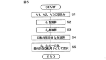
図5は、回転角演算装置20によって実行される回転角演算処理の手順を示すフローチャートである。
回転角演算処理は、所定の演算周期毎に繰り返し行なわれる。まず、回転角演算装置20は、各磁気センサ11,12,13の出力信号V1(=sinθ),V2(=sin(θ+90°)),V3(=sin(θ+180°))を取り込む(ステップS1)。そして、回転角演算装置20の第1の回転角演算部21は、ステップS1で取り込まれた出力信号V1,V2を用い、前記式(2)に基づいて、第1の回転角θ1を演算する(ステップS2)。
FIG. 5 is a flowchart showing the procedure of the rotation angle calculation process executed by the rotation
The rotation angle calculation process is repeated every predetermined calculation cycle. First, the rotation
また、回転角演算装置20の第2の回転角演算部22は、ステップS1で取り込まれた出力信号V2,V3を用い、前記式(3)に基づいて、第2の回転角θ2を演算する(ステップS3)。
また、回転角演算装置20の回転角選択部23は、第1の回転角θ1と第2の回転角θ2とに基づいて回転角推定値θEを演算する(ステップS4)。回転角選択部23は、たとえば、前記式(4)に基づいて、第1の回転角θ1と第2の回転角θ2の平均値を、回転角推定値θEとして求める。そして、回転角選択部23は、回転角推定値θEを用い、前記式(5)の条件式にしたがって、第1の回転角θ1および第2の回転角θ2のうちの一方を、最終的な回転角θとして選択する。(ステップS5)。
Further, the second rotation
Further, the rotation
前記第1の実施形態では、第1の回転角θ1および第2の回転角θ2のうち、演算誤差が小さい方の回転角を、ロータ1の最終的な回転角θとして選択することができるようになる。このため、回転角θの検出精度を高めることができる。
上記第1の実施形態では、磁気センサが3個設けられているが、磁気センサを4個以上設け、隣り合う2つのセンサの組毎にロータ1の回転角θに相当する回転角を演算することにより、最終的な回転角θの候補となる回転角を3種類以上求め、それらの回転角候補のうちの1つを、最終的な回転角θとして選択するようにしてもよい。
In the first embodiment, of the first rotation angle θ 1 and the second rotation angle θ 2 , the rotation angle with the smaller calculation error is selected as the final rotation angle θ of the
In the first embodiment, three magnetic sensors are provided. However, four or more magnetic sensors are provided, and a rotation angle corresponding to the rotation angle θ of the
図6は、この発明の第2の実施形態に係る回転角検出装置の構成を示す模式図である。
ロータ1の周囲には、2つの磁気センサ11,12が、ロータ1の周方向に間隔をおいて配置されている。これら2つの磁気センサ11,12を、それぞれ第1の磁気センサ11および第2の磁気センサ12という場合がある。第1の磁気センサ11と第2の磁気センサ12とは、ロータ1の回転中心軸を中心として、αの角度間隔をおいて配置されている。この実施形態では、αは90°に設定されている。
FIG. 6 is a schematic diagram showing a configuration of a rotation angle detection device according to the second embodiment of the present invention.
Around the
図6に矢印で示す方向をロータ1の正方向の回転方向とする。また、第1の実施形態と同様に、各磁気センサ11,12の出力信号を、その振幅が1であるものとして簡易的に表すことにする。ロータ1の回転角θに対して、第1の磁気センサ11からV1=sinθの出力信号V1が出力されるとすると、第2の磁気センサ12からは、V2=sin(θ+α)=sin(θ+90°)の出力信号V2が出力される。
A direction indicated by an arrow in FIG. 6 is a positive rotation direction of the
各磁気センサ11,12の出力信号V1,V2は、回転角演算装置40に入力される。回転角演算装置40は、各磁気センサ11,12の出力信号V1,V2に基づいて、ロータ1の回転角θを演算する。回転角演算装置40は、たとえば、マイクロコンピュータから構成され、CPU(中央演算処理装置)およびメモリ(ROM,RAM等)を含んでいる。回転角演算装置40は、ROMに格納された所定のプログラムをCPUが実行することにより、複数の機能処理部として機能する。この複数の機能処理部は、第1の回転角演算部(第1回転角演算手段)41、第2の回転角演算部(第2回転角演算手段)42および回転角選択部(最終回転角演算手段)43を含む。
Output signals
第1の回転角演算部41は、第1の磁気センサ11の出力信号V1と、第2の磁気センサ12の出力信号V2とに基づいて、次式(6)に示す演算式(以下、「第1演算式」という)を用いて、ロータ1の回転角に相当する第1の回転角θ1を演算する。この第1演算式は、第1の実施形態において説明した前記式(2)と同じである。
The first rotation
第2の回転角演算部42は、第1の磁気センサ11の出力信号V1と、第2の磁気センサ13の出力信号V3とに基づいて、次式(7)に示す演算式(以下、「第2演算式」という)を用いて、ロータ1の回転角に相当する第2の回転角θ2を演算する。
Based on the output signal V1 of the first
第2演算式の導き方について説明する。第1の出力信号V1は、sinθであるので、この信号V1を反転させることにより、V1’=−sinθで表される反転信号V1'を生成することができる。反転信号V1'は、V1'=−sinθ=sin(θ+180°)と表すことができるため、この反転信号V1’は、第1の実施形態における第3の出力信号V3と同様に、第1の出力信号V1に対し、位相が180°進んだ信号となる。言い換えれば、第2の出力信号V2(=sin(θ+90°))に対して、位相が90°進んだ信号となる。 A method for deriving the second arithmetic expression will be described. Since the first output signal V1 is sin θ, the inverted signal V1 ′ represented by V1 ′ = − sin θ can be generated by inverting the signal V1. Since the inverted signal V1 ′ can be expressed as V1 ′ = − sin θ = sin (θ + 180 °), the inverted signal V1 ′ is the same as the third output signal V3 in the first embodiment. This is a signal whose phase is advanced by 180 ° with respect to the output signal V1. In other words, the signal has a phase advanced by 90 ° with respect to the second output signal V2 (= sin (θ + 90 °)).
したがって、この反転信号V1’は、V1’=−sinθ=sin(θ+180°)=cos(θ+90°)と表すことができる。tan(θ+90°)は、tan(θ+90°)=sin(θ+90°)/cos(θ+90°)と表すことができる。したがって、回転角θは、θ=tan−1{sin(θ+90°)/−sinθ}−90°=tan−1(V2/−V1)−90°と表すことができる。この回転角θを第2の回転角θ2とすることにより、前記式(7)を導くことがてきる。 Therefore, this inverted signal V1 ′ can be expressed as V1 ′ = − sin θ = sin (θ + 180 °) = cos (θ + 90 °). tan (θ + 90 °) can be expressed as tan (θ + 90 °) = sin (θ + 90 °) / cos (θ + 90 °). Therefore, the rotation angle θ can be expressed as θ = tan −1 {sin (θ + 90 °) / − sin θ} −90 ° = tan −1 (V2 / −V1) −90 °. By this rotation angle theta and a second rotation angle theta 2, Tekiru be derived the equation (7).
回転角選択部43は、ロータ1の回転角推定値に応じて、第1の回転角θ1および第2の回転角θ2のうちのいずれか一方を、最終的な回転角θとして選択する。
第1の実施形態において、図2を用いて説明したように、第2の実施形態においても、ロータ1の回転角θが、90°付近の範囲(たとえば、90°±22.5°の範囲)および270°付近の範囲(たとえば、270°±22.5°の範囲)では、第1の回転角θ1の演算誤差が大きくなる。
The rotation
As described with reference to FIG. 2 in the first embodiment, also in the second embodiment, the rotation angle θ of the
第1の出力信号V1の反転信号V1’(=−sinθ)は、第1の実施形態の第3の出力信号V3=sin(θ+180°)と同様に、V1’=sin(θ+180°)と表すことができる。したがって、第2の実施形態における、V2=sin(θ+90°)、V1’=sin(−θ)およびsin(θ+90°)/−sinθを表す曲線は、それぞれ、図3におけるsin(θ+90°)、sin(θ+180°)およびsin(θ+90°)/sin(θ+180°)を表す曲線と同じになる。このため、第2の実施形態においても、図3に斜線部分で示すように、ロータ1の回転角θが、0°付近の範囲、180°付近の範囲および360°付近の範囲では、第2の回転角θ2の演算誤差が大きくなる。つまり、第2の実施形態においても、第1の回転角θ1と第2の回転角θ2とでは、演算誤差が大きくなるロータ角度範囲が異なる。
The inverted signal V1 ′ (= −sin θ) of the first output signal V1 is expressed as V1 ′ = sin (θ + 180 °), similarly to the third output signal V3 = sin (θ + 180 °) of the first embodiment. be able to. Therefore, the curves representing V2 = sin (θ + 90 °), V1 ′ = sin (−θ) and sin (θ + 90 °) / − sinθ in the second embodiment are sin (θ + 90 °) in FIG. This is the same as the curve representing sin (θ + 180 °) and sin (θ + 90 °) / sin (θ + 180 °). Therefore, also in the second embodiment, as indicated by the hatched portion in FIG. 3, when the rotation angle θ of the
そこで、回転角選択部43は、たとえば、第1の回転角θ1と第2の回転角θ2とからロータ1の回転角を推定し、推定された回転角(回転角推定値)に応じて、第1の回転角θ1および第2の回転角θ2のうちから、演算誤差が小さい(演算精度の高い)と推定される方を、最終的な回転角θとして選択する。
具体的には、回転角選択部43は、回転角推定部51と、選択部52とを備えている。
回転角推定部51は、たとえば、次式(8)に基づいて、第1の回転角θ1と第2の回転角θ2との平均を演算することにより、回転角推定値θEを求める。
Therefore, for example, the rotation
Specifically, the rotation
For example, the rotation
θE=(θ1+θ2)/2 …(8)
選択部52は、回転角推定部51によって得られた回転角推定値θEを用い、次式(9)に示す条件式にしたがって、第1の回転角θ1および第2の回転角θ2のうちの一方を、最終的な回転角θとして選択する。なお、この条件式は、第1の実施形態における条件式(前記式(5)参照)と同じである。
θ E = (θ 1 + θ 2 ) / 2 (8)
Selecting
If 0°≦θE<45° then θ=θ1
If 45°≦θE<135° then θ=θ2
If 135°≦θE<225° then θ=θ1
If 225°≦θE<315° then θ=θ2
If 315°≦θE<360° then θ=θ1 …(9)
図7は、回転角演算装置40によって実行される回転角演算処理の手順を示すフローチャートである。
If 0 ° ≦ θ E <45 ° then θ = θ 1
If 45 ° ≦ θ E <135 ° then θ = θ 2
If 135 ° ≦ θ E <225 ° then θ = θ 1
If 225 ° ≦ θ E <315 ° then θ = θ 2
If 315 ° ≦ θ E <360 ° then θ = θ 1 (9)
FIG. 7 is a flowchart showing the procedure of the rotation angle calculation process executed by the rotation
回転角演算処理は、所定の演算周期毎に繰り返し行なわれる。まず、回転角演算装置40は、各磁気センサ11,12の出力信号V1(=sinθ),V2(=sin(θ+90°))を取り込む(ステップS11)。そして、回転角演算装置40の第1の回転角演算部41は、ステップS11で取り込まれた出力信号V1,V2を用い、前記式(6)に示される第1演算式に基づいて、第1の回転角θ1を演算する(ステップS12)。
The rotation angle calculation process is repeated every predetermined calculation cycle. First, the rotation
また、回転角演算装置40の第2の回転角演算部42は、ステップS11で取り込まれた出力信号V1,V2を用い、前記式(7)に示される第2演算式に基づいて、第2の回転角θ2を演算する(ステップS13)。
また、回転角演算装置40の回転角選択部43は、第1の回転角θ1と第2の回転角θ2とに基づいて回転角推定値θEを演算する(ステップS14)。回転角選択部43は、たとえば、前記式(8)に基づいて、第1の回転角θ1と第2の回転角θ2の平均値を、回転角推定値θEとして求める。そして、回転角選択部43は、回転角推定値θEを用い、前記式(9)の条件式にしたがって、第1の回転角θ1および第2の回転角θ2のうちの一方を、最終的な回転角θとして選択する。(ステップS15)。
In addition, the second rotation
Further, the rotation
前記第2の実施形態においても、第1の回転角θ1および第2の回転角θ2のうち、演算誤差が小さい方の回転角を、ロータ1の最終的な回転角θとして選択することができるようになる。このため、回転角θの検出精度を高めることができる。第2の実施形態では、2個の磁気センサ11,12の出力信号V1,V2から、演算誤差が大きくなる角度範囲が互いに異なる、2種類の回転角θ1,θ2を演算することができるため、第1の実施形態に比べて、磁気センサの個数が少なくて済むという利点がある。
Also in the second embodiment, the rotation angle with the smaller calculation error out of the first rotation angle θ 1 and the second rotation angle θ 2 is selected as the final rotation angle θ of the
以上、この発明の第1および第2の実施形態について説明したが、この発明は、さらに他の形態で実施することもできる。たとえば、前述の第1および第2の実施形態では、回転角推定値θEに応じて、第1の回転角θ1および第2の回転角θ2のうちのいずれか一方が、最終的な回転角θとして選択されているが、第1の回転角θ1および第2の回転角θ2それぞれに回転角推定値θEに応じた重み付けをして加算することにより、最終的な回転角θを求めるようにしてもよい。 Although the first and second embodiments of the present invention have been described above, the present invention can also be implemented in other forms. For example, in the first and second embodiments described above, one of the first rotation angle θ 1 and the second rotation angle θ 2 is finally determined according to the rotation angle estimated value θ E. Although selected as the rotation angle θ, the final rotation angle is obtained by adding a weight corresponding to the estimated rotation angle θ E to each of the first rotation angle θ 1 and the second rotation angle θ 2. You may make it obtain | require (theta).
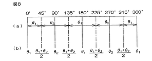
たとえば、前記式(5),(9)の条件式にしたがって回転角を選択する場合、第1の回転角θ1が選択される角度範囲と、第2の回転角θ2が選択される角度範囲は、図8(a)に示すようになる。そこで、図8(b)で示すように、回転角推定値θEが、第1の回転角θ1が選択される範囲の中央値である0°(360°)および180°に対しては、最終的な回転角θとして第1の回転角θ1を設定する。同様に、回転角推定値θEが、第2の回転角θ2が選択される範囲の中央値である90°および270°に対しては、最終的な回転角θとして第2の回転角θ2を設定する。 For example, the formula (5), the angle when selecting the rotation angle according to the conditional expression, where the angular range in which the first rotation angle theta 1 is selected, the second rotation angle theta 2 is selected in (9) The range is as shown in FIG. Therefore, as shown in FIG. 8B, the rotation angle estimated value θ E is not 0 ° (360 °) or 180 °, which is the median value of the range in which the first rotation angle θ 1 is selected. Then, the first rotation angle θ 1 is set as the final rotation angle θ. Similarly, with respect to 90 ° and 270 ° where the rotation angle estimated value θ E is the median value of the range in which the second rotation angle θ 2 is selected, the second rotation angle is the final rotation angle θ. θ 2 is set.
そして、0°<θE<90°の範囲、90°<θE<180°の範囲、180°<θE<270°の範囲および270°<θE<360°の範囲では、第1の回転角θ1および第2の回転角θ2にその範囲内の位置(角度:回転角推定値θE)に応じた重みw1,w2(w1+w2=1)を付けて加算した値を、最終的な回転角θ(=w1θ1+w2θ2)として設定する。具体的には、重みw1,w2は、次式(10)に基づいて求められる。 In the range of 0 ° <θ E <90 °, the range of 90 ° <θ E <180 °, the range of 180 ° <θ E <270 ° and the range of 270 ° <θ E <360 °, the first Weights w 1 and w 2 (w 1 + w 2 = 1) corresponding to positions within the range (angle: estimated rotation angle θ E ) are added to the rotation angle θ 1 and the second rotation angle θ 2 and added. The value is set as the final rotation angle θ (= w 1 θ 1 + w 2 θ 2 ). Specifically, the weights w 1 and w 2 are obtained based on the following equation (10).
このように重みw1,w2を設定した場合には、前記各範囲のちょうど中間位置(θE=45°,135°,225°,315°)では、第1の回転角θ1および第2の回転角θ2に対する重みw1,w2は共に0.5となるので、その位置に対する最終的な回転角θは第1の回転角θ1および第2の平均値((θ1+θ2)/2)となる。
前記第1および第2の実施形態では、第1の回転角θ1と第2の回転角θ2との平均を演算することによって、回転角推定値θEを求めているが、第1の回転角θ1または第2の回転角θ2のいずれかを、回転角推定値θEとして用いるようにしてもよい。また、第1の回転角θ1と第2の回転角θ2のいずれかが最終的な回転角θとして最初に選択された後においては、現在選択されている第1または第2の回転角θ1,θ2を回転角推定値θEとして用いるようにしてもよい。さらに、最終的な回転角が最初に演算された後においては、前回演算された最終的な回転角θを、今回の回転角推定値θEとして用いるようにしてもよい。
When the weights w 1 and w 2 are set in this way, at the intermediate positions (θ E = 45 °, 135 °, 225 °, 315 °) of the respective ranges, the first rotation angle θ 1 and the first rotation angle Since the weights w 1 and w 2 for the rotation angle θ 2 of 2 are both 0.5, the final rotation angle θ for the position is the first rotation angle θ 1 and the second average value ((θ 1 + θ 2 ) / 2).
In the first and second embodiments, the rotation angle estimation value θ E is obtained by calculating the average of the first rotation angle θ 1 and the second rotation angle θ 2 . one of the rotation angle theta 1 or the second rotation angle theta 2, may be used as the rotation angle estimated value theta E. In addition, after one of the first rotation angle θ 1 and the second rotation angle θ 2 is initially selected as the final rotation angle θ, the currently selected first or second rotation angle. You may make it use (theta) 1, ( theta) 2 as rotation angle estimated value (theta) E. Furthermore, the final rotation angle in after the first operation, a theta final rotation angle is previously calculated may be used as the current rotation angle estimated value theta E.
また、前記第1および第2の実施形態では、第1または第2の回転角θ1,θ2を、tan−1Xの演算を行なうことにより求めているが、tan−1Xの演算を行なわずに、たとえばマップにより、求めるようにしてもよい。
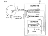
図9は、この発明の第3の実施形態に係る回転角検出装置の構成を示す模式図である。
ロータ1の周囲には、3つの磁気センサ61,62,63が、ロータ1の周方向に間隔をおいて配置されている。これら3つの磁気センサ61,62,63を、それぞれ第1の磁気センサ61、第2の磁気センサ62および第3の磁気センサ63という場合がある。第1の磁気センサ61と第2の磁気センサ62とは、ロータ1の回転中心軸を中心として、αの角度間隔をおいて配置されている。このαは、この例では、たとえば30°に設定されている。第1の磁気センサ61と第3の磁気センサ63とは、ロータ1の回転中心軸を中心として、αより大きなβの角度間隔をおいて配置されている。このβは、この例では、たとえば60°に設定されている。したがって、第2の磁気センサ62と第3の磁気センサ63との間の角度間隔は、(β−α)となる。この例では、(β−α)は、30°である。
Further, in the first and second embodiments, the rotation angle theta 1 of the first or second, the theta 2, although determined by performing the calculation of tan -1 X, the calculation of tan -1 X You may make it obtain | require, for example by a map, without performing.
FIG. 9 is a schematic diagram showing a configuration of a rotation angle detection device according to the third embodiment of the present invention.
Around the
図9に矢印で示す方向をロータ1の正方向の回転方向とする。また、第1の実施形態と同様に、各磁気センサ11,12の出力信号を、その振幅が1であるものとして簡易的に表すことにする。ロータ1の回転角θに対して、第1の磁気センサ61からV1=sinθの出力信号V1が出力されるとすると、第2の磁気センサ62からは、V2=sin(θ+α)の出力信号V2が出力され、第3の磁気センサ63からは、V3=sin(θ+β)の出力信号V3が出力される。
The direction indicated by the arrow in FIG. 9 is the positive rotation direction of the
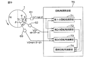
各磁気センサ61,62,63の出力信号V1,V2,V3は、回転角演算装置70に入力される。回転角演算装置70は、各磁気センサ61,62,63の出力信号V1,V2,V3に基づいて、ロータ1の回転角θを演算する。回転角演算装置70は、たとえば、マイクロコンピュータから構成され、CPU(中央演算処理装置)およびメモリ(ROM,RAM等)を含んでいる。回転角演算装置70は、ROMに格納された所定のプログラムをCPUが実行することにより、複数の機能処理部として機能する。この複数の機能処理部は、第1の回転角演算部(第1回転角演算手段)71、第2の回転角演算部(第2回転角演算手段)72、第3の回転角演算部(第3回転角演算手段)73および最終回転角演算部(最終回転角演算手段)74を含む。
Output signals V1, V2, and V3 of the
第1の回転角演算部71は、第1の磁気センサ61の出力信号V1と、第2の磁気センサ62の出力信号V2とに基づいて、ロータ1の回転角に相当する第1の回転角θ1を演算する。第2の回転角演算部72は、第1の磁気センサ61の出力信号V1と、第3の磁気センサ63の出力信号V3とに基づいて、ロータ1の回転角に相当する第2の回転角θ2を演算する。第3の回転角演算部73は、第2の磁気センサ62の出力信号V2と、第3の磁気センサ63の出力信号V3とに基づいて、ロータ1の回転角に相当する第3の回転角θ3を演算する。
The first rotation
最終回転角演算部74は、第1,第2および第3の回転角演算部71,72,73によってそれぞれ演算された第1,第2および第3の回転角θ1,θ2,θ3に基づいて、最終的な回転角θを演算する。
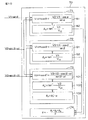
図10は、回転角演算装置70のさらに詳細な構成を示す機能ブロック図である。
第1の回転角演算部71は、信号生成部81と、角度演算部82とを含んでいる。信号生成部81は、第1の出力信号V1(=sinθ)と第2の出力信号V2(=sin(θ+α))とから、第1の出力信号V1に対する位相差が90°となる信号V12(=sin(θ+90°)=cosθ)を生成する。具体的には、信号生成部81は、次式(11)に基づいて、信号V12を生成する。
The final rotation
FIG. 10 is a functional block diagram showing a more detailed configuration of the rotation
The first rotation
つまり、信号生成部81は、第1の出力信号V1(=sinθ)と、第2の出力信号V2(=sin(θ+α))と、cosαと,sinαとから、信号V12(=cosθ)を生成する。cosα,sinαは、予めメモリに格納されている。なお、前記式(11)は、sin(θ+α)を三角関数の加法定理により展開した式に基づいて、導出することができる。
角度演算部82は、信号生成部81によって生成された信号V12(=cosθ)と第1の出力信号V1(=sinθ)とを用い、次式(12)に基づいて、第1の回転角θ1を演算する。
That is, the
The
第2の回転角演算部72は、信号生成部91と、角度演算部92とを含んでいる。信号生成部91は、第1の出力信号V1(=sinθ)と第3の出力信号V3(=sin(θ+β))とから、第1の出力信号V1に対する位相差が90°となる信号V13(=sin(θ+90°)=cosθ)を生成する。具体的には、信号生成部91は、次式(13)に基づいて、信号V13を生成する。
The second rotation
つまり、信号生成部91は、第1の出力信号V1(=sinθ)と、第3の出力信号V3(=sin(θ+β))と、cosβと,sinβとから、信号V13(=cosθ)を生成する。cosβ,sinβは、予めメモリに格納されている。なお、前記式(13)は、前記式(11)と同様に、sin(θ+β)を三角関数の加法定理により展開した式に基づいて、導出することができる。
That is, the
角度演算部92は、信号生成部91によって生成された信号V13(=cosθ2)と第1の出力信号V1(=sinθ)とを用い、次式(14)に基づいて、第2の回転角θ2を演算する。
The
第3の回転角演算部73による第3の回転角θ3の演算方法の考え方について説明する。第3の回転角演算部73は、まず、第2の出力信号V2と第3の出力信号V3とに基づいて、ロータ1の回転角θに対してαだけ進んだ回転角θ3’(=θ+α)を演算する。そして、得られた回転角θ3’からαを減算することにより、第3の回転角θ3を演算する。
The concept of the method for calculating the third rotation angle θ 3 by the third rotation
第3の回転角演算部73は、信号生成部101と、角度演算部102と、角度演算部103とを含んでいる。信号生成部101は、第2の出力信号V2(=sin(θ+α))と第3の出力信号V3(=sin(θ+β))とから、第2の出力信号V2に対する位相差が90°となる信号V23(=sin(θ+α+90°))を生成する。
θ’=θ+αとして、出力信号V2を正弦波信号sinθ’で表し、出力信号V3を、この正弦波信号sinθ’に対して位相差が(β−α)進んだ正弦波信号sin(θ’+(β−α))で表すと、前記第1の回転角演算部71と同様な方法により、正弦波信号sinθ’に対して位相差が90°となる信号V23(=sin(θ’+90°)=cosθ’)を求めることができる。
The third rotation
Assuming that θ ′ = θ + α, the output signal V2 is represented by a sine wave signal sin θ ′, and the output signal V3 is a sine wave signal sin (θ ′ +) whose phase difference is advanced by (β−α) with respect to the sine wave signal sin θ ′. (Β−α)), the signal V 23 (= sin (θ ′ + 90) having a phase difference of 90 ° with respect to the sine wave signal sin θ ′ is obtained by the same method as the first rotation
具体的には、信号生成部101は、次式(15)に基づいて、信号V23を生成する。
Specifically, the
つまり、信号生成部101は、第2の出力信号V2(=sin(θ+α))と、第3の出力信号V3(=sin(θ+β))と、cos(βーα)と、sin(βーα)とから、信号V23(=cosθ’)を生成する。cos(βーα)、sin(βーα)は、予めメモリに格納されている。
角度演算部102は、信号生成部101によって生成された信号V23(=cosθ’)と第2の出力信号V2(=sinθ’=sin(θ+α))とを用い、次式(16)に基づいて、回転角θ3’を演算する。
That is, the
The
角度演算部103は、次式(17)に基づいて、第3の回転角θ3を演算する。
θ3=θ3’−α …(17)
なお、αは予めメモリに格納されている。
最終回転角演算部74は、たとえば、次式(18)に基づいて、最終的な回転角θを演算する。つまり、最終回転角演算部74は、第1、第2および第3の回転角θ1,θ2,θ3の平均値を、最終的な回転角θとして演算する。
The
θ 3 = θ 3 '−α (17)
Α is stored in the memory in advance.
The final rotation
θ=(θ1+θ2+θ3)/3 …(18)
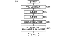
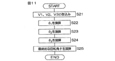
図11は、回転角演算装置70によって実行される回転角演算処理の手順を示すフローチャートである。
回転角演算処理は、所定の演算周期毎に繰り返し行なわれる。まず、回転角演算装置70は、各磁気センサ61,62,63の出力信号V1(=sinθ),V2(=sin(θ+α)),V3(=sin(θ+β))を取り込む(ステップS21)。そして、回転角演算装置70の第1の回転角演算部71は、ステップS21で取り込まれた出力信号V1,V2と、メモリに格納されているsinαおよびcosαの値と、前記式(11),(12)とを用いて、第1の回転角θ1を演算する(ステップS22)。
θ = (θ 1 + θ 2 + θ 3 ) / 3 (18)
FIG. 11 is a flowchart showing the procedure of the rotation angle calculation process executed by the rotation
The rotation angle calculation process is repeated every predetermined calculation cycle. First, the rotation
また、回転角演算装置70の第2の回転角演算部72は、ステップS21で取り込まれた出力信号V1,V3と、メモリに格納されているsinβおよびcosβの値と、前記式(13),(14)とを用いて、第2の回転角θ2を演算する(ステップS23)。
また、回転角演算装置70の第3の回転角演算部73は、ステップS21で取り込まれた出力信号V2,V3と、メモリに格納されているα、sin(β−α)およびcos(β−α)の値と、前記式(15),(16),(17)とを用いて、第3の回転角θ3を演算する(ステップS24)。
In addition, the second rotation
Further, the third rotation
そして、回転角演算装置70の最終回転角演算部74は、第1、第2および第3の回転角θ1,θ2,θ3に基づいて、最終的な回転角θを演算する(ステップS25)。たとえば、最終回転角演算部74は、前記式(18)に基づいて、第1、第2および第3の回転角θ1,θ2,θ3の平均値を、最終的な回転角θとして演算する。
前記第3の実施形態では、3つの回転角θ1,θ2,θ3の平均値が、最終的な回転角θとして求められている。このため、磁気センサの出力信号に含まれるノイズの影響による検出誤差を低減できる。また、最終的な回転角θは、同時刻に発生した出力信号V1,V2,V3から演算された3つの回転角θ1,θ2,θ3に基づいて演算されているので、時間方向に回転角を平均化することによって最終的な回転角を演算する場合に比べ、回転角検出に時間遅れが発生しない。このためロータ1の回転速度が大きい場合でも、高い応答性を実現できる。つまり、前記実施形態によれば、高い応答性を維持しつつ、ノイズの影響による検出誤差を低減できる。
Then, the final rotation
In the third embodiment, the average value of the three rotation angles θ 1 , θ 2 , θ 3 is obtained as the final rotation angle θ. For this reason, the detection error due to the influence of noise included in the output signal of the magnetic sensor can be reduced. Further, the final rotation angle θ is calculated based on the three rotation angles θ 1 , θ 2 , θ 3 calculated from the output signals V1, V2, and V3 generated at the same time. Compared to the case where the final rotation angle is calculated by averaging the rotation angles, no time delay occurs in the rotation angle detection. For this reason, even when the rotational speed of the
また、前記第3の実施形態では、第1,第2および第3の回転角θ1,θ2,θ3を演算する場合に、同じ磁気センサの出力信号を複数の回転角演算のために共用している。具体的には、信号V1は、θ1,θ2の演算のために共用され、信号V2はθ1,θ3の演算のために共用され、信号V3はθ2,θ3の演算のために共用されている。このため、同じ磁気センサの出力信号を複数の回転角演算のために共用しない場合に比べて、磁気センサの個数が少なくて済むという利点がある。具体的には、前記のように3種類の回転角を演算する場合、同じ磁気センサの出力信号を複数の回転角演算のために共用しないとすると、6個の磁気センサが必要となるが、この実施形態では3個で済む。 In the third embodiment, when calculating the first, second, and third rotation angles θ 1 , θ 2 , θ 3 , the output signal of the same magnetic sensor is used for calculating a plurality of rotation angles. Shared. Specifically, the signal V1 is shared for calculating θ 1 and θ 2 , the signal V2 is shared for calculating θ 1 and θ 3 , and the signal V3 is used for calculating θ 2 and θ 3. It is shared with. For this reason, there is an advantage that the number of magnetic sensors can be reduced as compared with a case where output signals of the same magnetic sensor are not shared for a plurality of rotation angle calculations. Specifically, when three types of rotation angles are calculated as described above, if the same output signal of the magnetic sensor is not used for calculation of a plurality of rotation angles, six magnetic sensors are required. In this embodiment, three is sufficient.
また、前記第3の実施形態では、最終回転角演算部74は、3つの回転角θ1,θ2,θ3の平均を最終的な回転角θとして演算しているが、3つの回転角θ1,θ2,θ3のうちの中央値を、最終的な回転角θとして演算するようにしてもよい。さらに、最終回転角演算部74は、3つの回転角θ1,θ2,θ3のうち、最も外れているものを除外し、他の2つの平均値を、最終的な回転角θとして演算するようにしてもよい。具体的には、3つの回転角θ1,θ2,θ3のうちの中央値と、他の2つの回転角のうち、中央値との差が小さいものとの平均値を、最終的な回転角θとする。
In the third embodiment, the final rotation
また、前記第3の実施形態では、磁気センサは3個設けられているが、磁気センサを4個以上設けるようにしてもよい。たとえば、磁気センサを4個設けた場合には、4個のセンサから2つのセンサをとる組み合わせは6通り存在するので、6種類の回転角を同時に検出することが可能となる。
その他、特許請求の範囲に記載された事項の範囲で種々の設計変更を施すことが可能である。
In the third embodiment, three magnetic sensors are provided, but four or more magnetic sensors may be provided. For example, when four magnetic sensors are provided, there are six combinations that take two sensors from the four sensors, so that six types of rotation angles can be detected simultaneously.
In addition, various design changes can be made within the scope of matters described in the claims.
また、この発明は、ブラシレスモータのロータ以外の回転体の回転角を検出する場合にも、適用することができる。 The present invention can also be applied when detecting the rotation angle of a rotating body other than the rotor of a brushless motor.
1…ロータ、11,12,13,61,62,63…磁気センサ
DESCRIPTION OF
Claims (2)
前記第1の正弦波信号と前記第2の正弦波信号とに基づいて、前記回転体の回転角に相当する第1の回転角を演算する第1回転角演算手段と、
前記第1の正弦波信号と前記第3の正弦波信号とに基づいて、前記回転体の回転角に相当する第2の回転角を演算する第2回転角演算手段と、
前記第2の正弦波信号と前記第3の正弦波信号とに基づいて、前記回転体の回転角に相当する第3の回転角を演算する第3回転角演算手段と、
前記第1、第2および第3の回転角に基づいて、最終的な回転角を演算する最終回転角演算手段とを含み、
前記第1のセンサは、前記回転体の回転角θに対して、V1=sinθで表される第1の正弦波信号V1を出力するものであり、
前記第2のセンサは、前記回転体の回転角θに対して、前記第1および第2の正弦波信号の位相差αを用いてV2=sin(θ+α)で表される第2の正弦波信号V2を出力するものであり、
前記第3のセンサは、前記回転体の回転角θに対して、前記第1および第3の正弦波信号の位相差βを用いてV3=sin(θ+β)で表される第3の正弦波信号V3を出力するものであり、
前記第1回転角演算手段は、次式(i)により、第1の回転角θ1を求めるものであり、
前記第2回転角演算手段は、次式(ii)により、第2の回転角θ2を求めるものであり、
前記第3回転角演算手段は、次式(iii)により、第3の回転角θ3を求めるものである、回転角検出装置。
First rotation angle calculation means for calculating a first rotation angle corresponding to the rotation angle of the rotating body based on the first sine wave signal and the second sine wave signal;
Based on the first sine wave signal and the third sine wave signal, second rotation angle calculating means for calculating a second rotation angle corresponding to the rotation angle of the rotating body;
Based on the second sine wave signal and the third sine wave signal, third rotation angle calculating means for calculating a third rotation angle corresponding to the rotation angle of the rotating body;
Final rotation angle calculation means for calculating a final rotation angle based on the first, second and third rotation angles,
The first sensor outputs a first sine wave signal V1 represented by V1 = sin θ with respect to a rotation angle θ of the rotating body,
The second sensor uses a phase difference α between the first and second sine wave signals with respect to the rotation angle θ of the rotating body to generate a second sine wave represented by V2 = sin (θ + α). Output the signal V2,
The third sensor uses a phase difference β between the first and third sine wave signals with respect to the rotation angle θ of the rotating body, and a third sine wave represented by V3 = sin (θ + β). Outputs the signal V3,
The first rotation angle calculation means calculates the first rotation angle θ1 by the following equation (i):
The second rotation angle calculation means obtains the second rotation angle θ2 by the following equation (ii):
The third rotation angle calculation means is a rotation angle detection device for obtaining the third rotation angle θ3 by the following equation (iii).
Priority Applications (5)
| Application Number | Priority Date | Filing Date | Title |
|---|---|---|---|
| JP2010166122A JP5557021B2 (en) | 2009-08-26 | 2010-07-23 | Rotation angle detector |
| EP10811781.3A EP2472233A4 (en) | 2009-08-26 | 2010-08-20 | Device for detecting angle of rotation |
| PCT/JP2010/064105 WO2011024731A1 (en) | 2009-08-26 | 2010-08-20 | Device for detecting angle of rotation |
| CN201080037552XA CN102575946A (en) | 2009-08-26 | 2010-08-20 | Device for detecting angle of rotation |
| US13/389,977 US20120143563A1 (en) | 2009-08-26 | 2010-08-20 | Rotation angle detection device |
Applications Claiming Priority (5)
| Application Number | Priority Date | Filing Date | Title |
|---|---|---|---|
| JP2009195191 | 2009-08-26 | ||
| JP2009195190 | 2009-08-26 | ||
| JP2009195191 | 2009-08-26 | ||
| JP2009195190 | 2009-08-26 | ||
| JP2010166122A JP5557021B2 (en) | 2009-08-26 | 2010-07-23 | Rotation angle detector |
Publications (3)
| Publication Number | Publication Date |
|---|---|
| JP2011069815A JP2011069815A (en) | 2011-04-07 |
| JP2011069815A5 JP2011069815A5 (en) | 2013-09-12 |
| JP5557021B2 true JP5557021B2 (en) | 2014-07-23 |
Family
ID=43627837
Family Applications (1)
| Application Number | Title | Priority Date | Filing Date |
|---|---|---|---|
| JP2010166122A Expired - Fee Related JP5557021B2 (en) | 2009-08-26 | 2010-07-23 | Rotation angle detector |
Country Status (5)
| Country | Link |
|---|---|
| US (1) | US20120143563A1 (en) |
| EP (1) | EP2472233A4 (en) |
| JP (1) | JP5557021B2 (en) |
| CN (1) | CN102575946A (en) |
| WO (1) | WO2011024731A1 (en) |
Families Citing this family (16)
| Publication number | Priority date | Publication date | Assignee | Title |
|---|---|---|---|---|
| JP5660381B2 (en) * | 2011-03-09 | 2015-01-28 | 株式会社ジェイテクト | Rotation angle detector |
| GB201110039D0 (en) * | 2011-06-15 | 2011-07-27 | Trw Ltd | Measurement of motor rotor position or speed |
| JP6024970B2 (en) * | 2012-12-12 | 2016-11-16 | 株式会社ジェイテクト | Rotation angle detection device and electric power steering device having the same |
| JP6024969B2 (en) | 2012-12-12 | 2016-11-16 | 株式会社ジェイテクト | Rotation angle detection device and electric power steering device having the same |
| JP6086205B2 (en) * | 2012-12-12 | 2017-03-01 | 株式会社ジェイテクト | Phase difference detection device and rotation angle detection device including the same |
| JP6024971B2 (en) | 2012-12-12 | 2016-11-16 | 株式会社ジェイテクト | Rotation angle detector |
| JP6377335B2 (en) * | 2013-10-28 | 2018-08-22 | 日本電産サンキョー株式会社 | Data detection method and detection device in detection device |
| JP6548646B2 (en) * | 2014-06-30 | 2019-07-24 | Phcホールディングス株式会社 | Rotation angle detection circuit, rotation angle detection method, sample analyzer and computer program for sample analyzer |
| DE102015212812A1 (en) * | 2015-07-08 | 2017-01-12 | Conti Temic Microelectronic Gmbh | Operation of a rotating electrical machine |
| JP2017138143A (en) * | 2016-02-02 | 2017-08-10 | Tdk株式会社 | Displacement detection device and angular speed detection device |
| CN107461288B (en) * | 2016-06-03 | 2018-12-25 | 纳博特斯克有限公司 | Detection device and starting device |
| JP6758998B2 (en) * | 2016-08-24 | 2020-09-23 | Ntn株式会社 | Electric motor device |
| JP7035608B2 (en) * | 2018-02-22 | 2022-03-15 | 株式会社デンソーウェーブ | Robot arm rotation axis speed detector |
| CN111294457B (en) * | 2018-12-10 | 2021-06-29 | 北京小米移动软件有限公司 | Sliding closure type terminal, sliding closure state detection method and device and storage medium |
| JP7172797B2 (en) * | 2019-03-28 | 2022-11-16 | 株式会社デンソー | detection unit |
| JP7287375B2 (en) * | 2020-10-23 | 2023-06-06 | Tdk株式会社 | Magnetic sensor assembly and camera module with same |
Family Cites Families (22)
| Publication number | Priority date | Publication date | Assignee | Title |
|---|---|---|---|---|
| JPH0555022A (en) | 1991-08-26 | 1993-03-05 | Sankyo Seiki Mfg Co Ltd | Rare-earth bonded magnet |
| JPH09508214A (en) | 1994-11-22 | 1997-08-19 | ローベルト ボツシユ ゲゼルシヤフト ミツト ベシユレンクテル ハフツング | Non-contact rotation angle detection device for rotatable members |
| DE19941101B4 (en) * | 1999-08-30 | 2008-01-17 | Delphi Technologies, Inc., Troy | sensor arrangement |
| JP2001114116A (en) * | 1999-10-19 | 2001-04-24 | Alps Electric Co Ltd | Rotation angle detecting device |
| JP2001324321A (en) | 2000-03-07 | 2001-11-22 | Koyo Seiko Co Ltd | Rotation angle detector, torque detector, and steering device |
| JP2002213944A (en) | 2001-01-18 | 2002-07-31 | Niles Parts Co Ltd | Instrument for measuring rotational angle |
| JP2003240598A (en) * | 2002-02-13 | 2003-08-27 | Asahi Kasei Corp | Digital angle measuring system |
| JP2004156961A (en) | 2002-11-05 | 2004-06-03 | Koyo Seiko Co Ltd | Rotation angle sensitive device and torque sensing device |
| JP2004264167A (en) * | 2003-03-03 | 2004-09-24 | Midori Sokki:Kk | Rotation angle sensor |
| JP4763296B2 (en) * | 2005-01-18 | 2011-08-31 | 古河電気工業株式会社 | Detection device |
| WO2006085569A1 (en) * | 2005-02-10 | 2006-08-17 | Matsushita Electric Industrial Co., Ltd. | Rotation angle detection device and rotation angle correction method |
| CN100545580C (en) * | 2005-06-30 | 2009-09-30 | 株式会社村田制作所 | Pick-up unit and rotation angle sensor |
| JP4797721B2 (en) * | 2005-10-20 | 2011-10-19 | 株式会社デンソー | Rotation angle detector |
| JP2007155618A (en) * | 2005-12-07 | 2007-06-21 | Denso Corp | Rotation angle detection device |
| JP2008045881A (en) * | 2006-08-10 | 2008-02-28 | Nsk Ltd | Rotation angle position detector |
| JP2008128961A (en) * | 2006-11-24 | 2008-06-05 | Alps Electric Co Ltd | Absolute angle detector |
| KR100847491B1 (en) * | 2007-03-20 | 2008-07-21 | 대성전기공업 주식회사 | Error detecting device for steering angle sensor and mathod of the sensor |
| JP2008241411A (en) | 2007-03-27 | 2008-10-09 | Jtekt Corp | Device for detecting steering angle |
| DE112007003469B4 (en) * | 2007-04-24 | 2014-12-11 | Harmonic Drive Systems Inc. | Magnetic encoder and method of detecting an absolute rotational position |
| JP2009195191A (en) | 2008-02-22 | 2009-09-03 | Hayashi Bussan Hatsumei Kenkyusho:Kk | Moss or creeping plant raising tool |
| JP4990815B2 (en) | 2008-02-22 | 2012-08-01 | パナソニック株式会社 | Pest control equipment |
| JP2010166122A (en) | 2009-01-13 | 2010-07-29 | Olympus Corp | Imaging device and image processing method |
-
2010
- 2010-07-23 JP JP2010166122A patent/JP5557021B2/en not_active Expired - Fee Related
- 2010-08-20 WO PCT/JP2010/064105 patent/WO2011024731A1/en active Application Filing
- 2010-08-20 CN CN201080037552XA patent/CN102575946A/en active Pending
- 2010-08-20 EP EP10811781.3A patent/EP2472233A4/en not_active Withdrawn
- 2010-08-20 US US13/389,977 patent/US20120143563A1/en not_active Abandoned
Also Published As
| Publication number | Publication date |
|---|---|
| CN102575946A (en) | 2012-07-11 |
| EP2472233A1 (en) | 2012-07-04 |
| JP2011069815A (en) | 2011-04-07 |
| WO2011024731A1 (en) | 2011-03-03 |
| US20120143563A1 (en) | 2012-06-07 |
| EP2472233A4 (en) | 2014-06-18 |
Similar Documents
| Publication | Publication Date | Title |
|---|---|---|
| JP5557021B2 (en) | Rotation angle detector | |
| JP5807770B2 (en) | Rotation angle detector | |
| JP5716954B2 (en) | Rotation angle detector | |
| US10775200B2 (en) | Rotary encoder and absolute angular position detection method thereof | |
| JP5333863B2 (en) | Rotation angle detector | |
| US9605974B2 (en) | Rotation angle detecting device | |
| TWI650528B (en) | Rotation angle detecting device and rotation angle detecting method | |
| US8836326B2 (en) | Rotation angle detection device | |
| JP4317173B2 (en) | Method and system for detecting direction of moving object | |
| JP5720932B2 (en) | Rotation angle detector | |
| JP2011069815A5 (en) | ||
| JP2008116291A (en) | Rotation detector and bearing with the rotation detector | |
| JP2011047735A (en) | Rotational angle detecting device | |
| JP2014013209A (en) | Angle detection device | |
| JP5082481B2 (en) | Rotational angle position calculation device and motor | |
| JP5454918B2 (en) | Rotation angle detector | |
| JP2012073053A (en) | Rotation angle detection device | |
| JP7224309B2 (en) | Angle detector | |
| JP6377335B2 (en) | Data detection method and detection device in detection device | |
| JP2004045083A (en) | Detecting device for rotation angle | |
| JP2016080408A (en) | Rotation angle detection circuit | |
| JP2004325317A (en) | Rotating angle computing unit and rotation angle detector | |
| JP2004077133A (en) | Initial setting method of rotational angle detecting apparatus | |
| JP6221307B2 (en) | Rotation angle detection device and electric power steering device | |
| JP2021110583A (en) | Angle detection device |
Legal Events
| Date | Code | Title | Description |
|---|---|---|---|
| A621 | Written request for application examination |
Free format text: JAPANESE INTERMEDIATE CODE: A621 Effective date: 20130620 |
|
| A521 | Written amendment |
Free format text: JAPANESE INTERMEDIATE CODE: A523 Effective date: 20130729 |
|
| A131 | Notification of reasons for refusal |
Free format text: JAPANESE INTERMEDIATE CODE: A131 Effective date: 20130801 |
|
| A131 | Notification of reasons for refusal |
Free format text: JAPANESE INTERMEDIATE CODE: A131 Effective date: 20131003 |
|
| A521 | Written amendment |
Free format text: JAPANESE INTERMEDIATE CODE: A523 Effective date: 20131122 |
|
| A131 | Notification of reasons for refusal |
Free format text: JAPANESE INTERMEDIATE CODE: A131 Effective date: 20131212 |
|
| A521 | Written amendment |
Free format text: JAPANESE INTERMEDIATE CODE: A523 Effective date: 20140127 |
|
| TRDD | Decision of grant or rejection written | ||
| A01 | Written decision to grant a patent or to grant a registration (utility model) |
Free format text: JAPANESE INTERMEDIATE CODE: A01 Effective date: 20140508 |
|
| A61 | First payment of annual fees (during grant procedure) |
Free format text: JAPANESE INTERMEDIATE CODE: A61 Effective date: 20140521 |
|
| R150 | Certificate of patent or registration of utility model |
Ref document number: 5557021 Country of ref document: JP Free format text: JAPANESE INTERMEDIATE CODE: R150 |
|
| LAPS | Cancellation because of no payment of annual fees |