JP5554334B2 - Method and apparatus for foam-based interface structure - Google Patents
Method and apparatus for foam-based interface structure Download PDFInfo
- Publication number
- JP5554334B2 JP5554334B2 JP2011526353A JP2011526353A JP5554334B2 JP 5554334 B2 JP5554334 B2 JP 5554334B2 JP 2011526353 A JP2011526353 A JP 2011526353A JP 2011526353 A JP2011526353 A JP 2011526353A JP 5554334 B2 JP5554334 B2 JP 5554334B2
- Authority
- JP
- Japan
- Prior art keywords
- cushion
- face mask
- foam
- patient
- region
- Prior art date
- Legal status (The legal status is an assumption and is not a legal conclusion. Google has not performed a legal analysis and makes no representation as to the accuracy of the status listed.)
- Active
Links
Images


Classifications
-
- A—HUMAN NECESSITIES
- A61—MEDICAL OR VETERINARY SCIENCE; HYGIENE
- A61M—DEVICES FOR INTRODUCING MEDIA INTO, OR ONTO, THE BODY; DEVICES FOR TRANSDUCING BODY MEDIA OR FOR TAKING MEDIA FROM THE BODY; DEVICES FOR PRODUCING OR ENDING SLEEP OR STUPOR
- A61M16/00—Devices for influencing the respiratory system of patients by gas treatment, e.g. mouth-to-mouth respiration; Tracheal tubes
- A61M16/06—Respiratory or anaesthetic masks
- A61M16/0605—Means for improving the adaptation of the mask to the patient
- A61M16/0616—Means for improving the adaptation of the mask to the patient with face sealing means comprising a flap or membrane projecting inwards, such that sealing increases with increasing inhalation gas pressure
- A61M16/0622—Means for improving the adaptation of the mask to the patient with face sealing means comprising a flap or membrane projecting inwards, such that sealing increases with increasing inhalation gas pressure having an underlying cushion
-
- A—HUMAN NECESSITIES
- A61—MEDICAL OR VETERINARY SCIENCE; HYGIENE
- A61M—DEVICES FOR INTRODUCING MEDIA INTO, OR ONTO, THE BODY; DEVICES FOR TRANSDUCING BODY MEDIA OR FOR TAKING MEDIA FROM THE BODY; DEVICES FOR PRODUCING OR ENDING SLEEP OR STUPOR
- A61M16/00—Devices for influencing the respiratory system of patients by gas treatment, e.g. mouth-to-mouth respiration; Tracheal tubes
- A61M16/06—Respiratory or anaesthetic masks
- A61M16/0605—Means for improving the adaptation of the mask to the patient
-
- A—HUMAN NECESSITIES
- A61—MEDICAL OR VETERINARY SCIENCE; HYGIENE
- A61M—DEVICES FOR INTRODUCING MEDIA INTO, OR ONTO, THE BODY; DEVICES FOR TRANSDUCING BODY MEDIA OR FOR TAKING MEDIA FROM THE BODY; DEVICES FOR PRODUCING OR ENDING SLEEP OR STUPOR
- A61M16/00—Devices for influencing the respiratory system of patients by gas treatment, e.g. mouth-to-mouth respiration; Tracheal tubes
- A61M16/06—Respiratory or anaesthetic masks
- A61M16/0683—Holding devices therefor
- A61M16/0688—Holding devices therefor by means of an adhesive
-
- A—HUMAN NECESSITIES
- A61—MEDICAL OR VETERINARY SCIENCE; HYGIENE
- A61M—DEVICES FOR INTRODUCING MEDIA INTO, OR ONTO, THE BODY; DEVICES FOR TRANSDUCING BODY MEDIA OR FOR TAKING MEDIA FROM THE BODY; DEVICES FOR PRODUCING OR ENDING SLEEP OR STUPOR
- A61M16/00—Devices for influencing the respiratory system of patients by gas treatment, e.g. mouth-to-mouth respiration; Tracheal tubes
- A61M16/06—Respiratory or anaesthetic masks
- A61M16/0605—Means for improving the adaptation of the mask to the patient
- A61M16/0633—Means for improving the adaptation of the mask to the patient with forehead support
-
- A—HUMAN NECESSITIES
- A61—MEDICAL OR VETERINARY SCIENCE; HYGIENE
- A61M—DEVICES FOR INTRODUCING MEDIA INTO, OR ONTO, THE BODY; DEVICES FOR TRANSDUCING BODY MEDIA OR FOR TAKING MEDIA FROM THE BODY; DEVICES FOR PRODUCING OR ENDING SLEEP OR STUPOR
- A61M2207/00—Methods of manufacture, assembly or production
- A61M2207/10—Device therefor
-
- A—HUMAN NECESSITIES
- A61—MEDICAL OR VETERINARY SCIENCE; HYGIENE
- A61M—DEVICES FOR INTRODUCING MEDIA INTO, OR ONTO, THE BODY; DEVICES FOR TRANSDUCING BODY MEDIA OR FOR TAKING MEDIA FROM THE BODY; DEVICES FOR PRODUCING OR ENDING SLEEP OR STUPOR
- A61M2209/00—Ancillary equipment
- A61M2209/02—Equipment for testing the apparatus
Description
出願への相互参照
本出願は、2008年9月12日に出願されたオーストラリア国仮特許出願第AU2008904769号、および2008年9月15日に出願されたオーストラリア国仮特許出願第AU2008904778号の利益を主張し、そのそれぞれを、参照により本明細書にその全体を組み込む。
This application is based on the benefits of Australian Provisional Patent Application No. AU2008904769 filed on September 12, 2008 and Australian Provisional Patent Application No. AU2008904778 filed on September 15, 2008 Each of which is hereby incorporated by reference in its entirety.
本発明は、人と1つの機器、例えば、発泡体ベースのインターフェース構造を含む呼吸装置との間のインターフェースに関する。 The present invention relates to an interface between a person and a device, for example a breathing apparatus including a foam-based interface structure.
呼吸療法などのいくつかの分野では、治療を行うための装置は、剛性のあるコンポーネントと、患者とその剛性のあるコンポーネントの間に配置される柔軟なクッション性コンポーネントとを含む。 In some areas, such as respiratory therapy, a device for performing treatment includes a rigid component and a flexible cushioning component disposed between the patient and the rigid component.
呼吸装置の場合、剛性のあるコンポーネントは、鼻および/または口を受け入れるチャンバを画定するマスクフレームとすることができる。マスクフレームは、その周囲にフランジを、または他の接続手段を含むことができる。クッション性コンポーネントは、フランジまたは接続手段に接着されるか、あるいはその他の形で結合されうる。 In the case of a respiratory device, the rigid component can be a mask frame that defines a chamber that receives the nose and / or mouth. The mask frame may include a flange around it or other connection means. The cushioning component can be glued to the flange or connecting means or otherwise joined.
クッション性コンポーネントは、何らかの形の呼吸療法において、患者の皮膚とのシールを形成することができる。例えば、ヘッドホンなどの他の装置では、シールを形成する必要はない可能性もある。 The cushioning component can form a seal with the patient's skin in some form of respiratory therapy. For example, in other devices such as headphones, it may not be necessary to form a seal.
本発明の第1の態様は、発泡体インターフェース構造を有するマスクアセンブリを提供することである。 A first aspect of the present invention is to provide a mask assembly having a foam interface structure.
本発明の他の態様は、発泡体インターフェース構造を有するマスクアセンブリを提供することであり、その場合、発泡体の少なくとも一部(例えば、発泡体のスキンが除去された部分)は、マスクユーザの皮膚と直接接触する。 Another aspect of the present invention is to provide a mask assembly having a foam interface structure, wherein at least a portion of the foam (e.g., the portion of the foam skin removed) is masked by the mask user. Direct contact with skin.
本発明の他の態様は、発泡体インターフェース構造を有するマスクアセンブリを提供することであり、その場合、発泡体はスキンが除去され、マスクユーザの皮膚と直接接触する発泡体の気泡構造を有する。 Another aspect of the present invention is to provide a mask assembly having a foam interface structure, wherein the foam has a foam cellular structure with the skin removed and in direct contact with the mask user's skin.
本発明の他の態様は、取外し可能な発泡体インターフェース構造を有するマスクアセンブリを提供することである。 Another aspect of the present invention is to provide a mask assembly having a removable foam interface structure.
本発明の他の態様は、少なくとも2つの異なるタイプの、取り外して交換可能なインターフェース構造を有するマスクアセンブリを提供することである。 Another aspect of the present invention is to provide a mask assembly having at least two different types of removable and replaceable interface structures.
本発明の他の態様は、より剛性のあるコンポーネントと係合するように適合された部分を有する、より柔軟性のあるインターフェース構造を含むことである。 Another aspect of the present invention is to include a more flexible interface structure having a portion adapted to engage a more rigid component.
本発明の他の態様は、フレームおよびインターフェース構造を含む呼吸マスクアセンブリを提供することであり、その場合、インターフェース構造は、発泡体ベースのクッションコンポーネントと、フレーム部と取外し可能に係合するように適合されたクリップ部とを含む。 Another aspect of the present invention is to provide a respiratory mask assembly that includes a frame and an interface structure, wherein the interface structure is removably engaged with a foam-based cushion component and the frame portion. And an adapted clip portion.
本発明の他の態様は、クッション性コンポーネントに対する支持構造を提供することであり、その場合、支持構造は、一方の側でクッション性要素を支持し、他方の側で動くこと可能にする。 Another aspect of the invention is to provide a support structure for the cushioning component, in which case the support structure supports the cushioning element on one side and allows movement on the other side.
本発明の他の態様は、クリップ部およびクッション性コンポーネントを含む呼吸マスクのためのクッションに関し、その場合、クッション性コンポーネントは、発泡体材料から構成され、またクリップ部は、クッション性コンポーネントより狭い。 Another aspect of the invention relates to a cushion for a respiratory mask that includes a clip portion and a cushioning component, where the cushioning component is constructed from a foam material and the clip portion is narrower than the cushioning component.
本発明の他の態様は、チャネルを有するフレームと、チャネル中で締り嵌めシールを行い、かつ保持するように適合されたクリップ部を含むインターフェース構造とを含む呼吸マスクアセンブリに関する。インターフェース構造は、発泡体から構成され、クリップ部よりも広い幅を有するクッションコンポーネントを含む。 Another aspect of the invention relates to a respiratory mask assembly that includes a frame having a channel and an interface structure including a clip portion adapted to provide and hold an interference fit seal in the channel. The interface structure includes a cushion component made of foam and having a wider width than the clip portion.
他の態様は、好ましくは、鼻橋領域に第1の横断面、唇領域に第2の横断面、頬領域に第3の横断面を有する発泡体ベースのクッション性コンポーネントである。 Another embodiment is a foam-based cushioning component that preferably has a first cross section in the nasal bridge region, a second cross section in the lip region, and a third cross section in the cheek region.
他の態様は、例えば、打抜きおよび/または機械加工など、クッション性コンポーネントを製造する方法である。 Another aspect is a method of manufacturing a cushioning component, such as, for example, stamping and / or machining.
他の態様は、インターフェース構造を形成するために、クリップコンポーネントをクッション性コンポーネントへとインサート成形する方法である。 Another aspect is a method of insert molding a clip component into a cushioning component to form an interface structure.
他の態様は、マスクと共に使用するためのクッション性コンポーネントであり、クッション性コンポーネントは発泡材料から構成される。使用時に、患者と接触するように適合された患者接触面は、丸い横断面輪郭(rounded cross sectional profile)を有することができ、またベース面は、患者接触面の反対側にある。 Another aspect is a cushioning component for use with a mask, the cushioning component being constructed from a foam material. In use, a patient contact surface adapted to contact a patient can have a rounded cross sectional profile and the base surface is opposite the patient contact surface.
他の態様は、発泡体材料から構成されたクッション性コンポーネントを含むマスクで使用するための取外し可能なインターフェース構造であり、使用時に、患者と接触するように適合された患者接触面は、丸い横断面輪郭を有し、また患者接触面の反対側にあるベース面は、クリップ部に結合され、さらにクリップ部はマスクのフレームに対して取外し可能に結合されるように適合される。 Another aspect is a removable interface structure for use with a mask that includes a cushioning component constructed from a foam material, wherein the patient contact surface adapted to contact the patient in use has a round crossing A base surface having a surface profile and opposite the patient contact surface is coupled to the clip portion, and the clip portion is further adapted to be removably coupled to the frame of the mask.
他の態様は、取外し可能なインターフェース構造およびフレームを含むマスクであり、インターフェース構造は、クリップ部と、発泡材料から構成されるクッション性コンポーネントであって、使用時に患者と接触するように適合され、丸い横断面輪郭を有する患者接触面、およびクリップ部に結合される患者接触面の反対側にあるベース面を有するクッション性コンポーネントとを含み、クリップ部は、マスクのフレームに取外し可能に結合されるように適合される。 Another aspect is a mask comprising a removable interface structure and a frame, the interface structure being a cushioning component comprised of a clip portion and foam material, adapted to contact a patient in use, A cushioning component having a patient contact surface having a round cross-sectional profile and a base surface opposite the patient contact surface coupled to the clip portion, wherein the clip portion is removably coupled to the frame of the mask To be adapted.
他の態様は、フレームおよびインターフェース構造を含むマスクであり、インターフェース構造は、クッション性コンポーネントに結合されたクリップ部を含み、またフレームは、クリップ部よりも剛性があり、またクリップ部は、クッション性部分よりも剛性がある。 Another aspect is a mask that includes a frame and an interface structure, the interface structure including a clip portion coupled to the cushioning component, the frame is more rigid than the clip portion, and the clip portion is cushioned. More rigid than part.
他の態様は、マスクと共に使用するためのクッション性コンポーネントであり、クッション性コンポーネントの横断面の少なくとも一部は、マスクの中心に向いている側面により画定される内側面と、マスクの中心から離れる方向を向いている側面により画定される外側面と、フレームもしくはクリップ部に向いているベース側面とを含み、外側面の長さが内側面よりも大きい。 Another aspect is a cushioning component for use with a mask, wherein at least a portion of the cross-section of the cushioning component is spaced from an inner surface defined by a side facing the center of the mask and the center of the mask It includes an outer side defined by a side facing direction and a base side facing the frame or clip portion, the outer side being longer than the inner side.
他の態様は、クッション性コンポーネントに結合されるクリップ部を含むマスクのためのインターフェース構造であり、クリップ部の上面は、クッション性コンポーネントのべース面に結合され、また上面の少なくとも一部には、クッション性コンポーネントに力が加えられたとき、クッション性コンポーネントに対してモーメント力を提供するように角度が付けられている。 Another aspect is an interface structure for a mask that includes a clip portion that is coupled to a cushioning component, wherein the upper surface of the clip portion is coupled to a base surface of the cushioning component and is at least a portion of the upper surface. Are angled to provide a moment force against the cushioning component when a force is applied to the cushioning component.
他の態様は、クッション性コンポーネントに結合されるクリップ部を含むマスクに対するインターフェース構造であり、クリップ部の上面はクッション性コンポーネントのベース面に結合され、またクリップ部の横断面幅は、クッション性コンポーネントの横断面幅未満である。 Another aspect is an interface structure for a mask that includes a clip portion that is coupled to a cushioning component, wherein the top surface of the clip portion is coupled to the base surface of the cushioning component, and the cross-sectional width of the clip portion is Less than the cross-sectional width.
他の態様は、マスクと共に使用するためのクッション性コンポーネントであり、クッション性コンポーネントの横断面の少なくとも一部は、マスクの中心を向いている側面により画定される内側面と、マスクの中心から離れる方向を向いている側面により画定される外側面と、フレームもしくはクリップ部を向いているベース側面とを含み、外側面は、少なくとも上側部分および下側部分をさらに含み、上側部分は、下側部分と比較して小さい角度で配置される。 Another aspect is a cushioning component for use with a mask, wherein at least a portion of the cross-section of the cushioning component is spaced from an inner surface defined by a side facing the center of the mask and the center of the mask An outer surface defined by a side facing direction and a base side facing a frame or clip portion, the outer surface further including at least an upper portion and a lower portion, wherein the upper portion is a lower portion It is arranged at a small angle compared to
他の態様は、インターフェース構造と取外し可能に接続されたフレームを含む鼻マスクであり、インターフェース構造は、発泡材料から構成されたクッション性コンポーネントを含み、またインターフェース構造の高さは、患者の顔の上唇領域に接触するように適合された領域に関して低減される。 Another aspect is a nasal mask that includes a frame that is removably connected to the interface structure, the interface structure including a cushioning component composed of foam material, and the height of the interface structure is the height of the patient's face. Reduced with respect to the region adapted to contact the upper lip region.
本技術の一態様は、フレーム、発泡体クッション、および下部構造(substructure)を含む呼吸マスクに関する。マスクは、鼻を受け入れる空洞を含む。クッションは、少なくとも2つの側面を含む。すなわち、少なくとも部分的に空洞に向いている壁でありうる内側の側壁と、外側の側壁である。発泡体クッションは、柔軟であり、かつ適応性がある。下部構造は、より剛性のある材料から構成される。発泡体クッションは、患者の顔の少なくとも1つの領域とシールを形成するように適合される。使用時に、発泡体クッションは、下部構造により支持される。下部構造の接続面が画定される。発泡体クッションの患者側が画定される。クッションの非患者側(non-patient side)が画定される。使用時に、クッションの非患者側は、下部構造の接続面に隣接して配置される。一形態では、発泡体クッションは、下部構造に接着される。他の形態では、発泡体クッションは、下部構造と共にインサート成形される。顔の第1の領域は、患者の口角として画定される。顔の第2の領域は、下顎領域として画定される、または代替的には、患者の顔の唇領域として画定される。クッションの内側領域は、使用時に患者の鼻が挿入される領域または空洞として画定される。 One aspect of the present technology relates to a respiratory mask that includes a frame, a foam cushion, and a substructure. The mask includes a cavity that receives the nose. The cushion includes at least two sides. That is, an inner sidewall that can be a wall that is at least partially facing the cavity, and an outer sidewall. The foam cushion is flexible and adaptable. The substructure is composed of a more rigid material. The foam cushion is adapted to form a seal with at least one region of the patient's face. In use, the foam cushion is supported by the substructure. A connecting surface of the substructure is defined. A patient side of the foam cushion is defined. A non-patient side of the cushion is defined. In use, the non-patient side of the cushion is positioned adjacent to the connecting surface of the substructure. In one form, the foam cushion is bonded to the substructure. In another form, the foam cushion is insert molded with the substructure. The first area of the face is defined as the patient's mouth corner. The second area of the face is defined as the lower jaw area, or alternatively as the lip area of the patient's face. The inner area of the cushion is defined as the area or cavity into which the patient's nose is inserted in use.
一形態では、使用時に第1の領域に隣接する接続面の一部は、使用時に第1の領域にあるクッションの内側領域への内側方向に、発泡体クッションの対応する部分を導くように構成される。クッションの横断面は半径方向軸を規定し、また長手方向軸は、前記半径方向軸に対して直角である。好ましくは、発泡体クッションの少なくとも一部は、患者の顔により圧力がクッションに加えられたとき、前記長手方向軸の周りでマスクの中心方向に回転するように適合され、前記クッションの外側の側壁の少なくとも一部が、患者の顔に対してシールを形成するように適合される。 In one form, a portion of the connecting surface adjacent to the first region in use is configured to guide a corresponding portion of the foam cushion inwardly toward the inner region of the cushion in the first region during use. Is done. The cross section of the cushion defines a radial axis, and the longitudinal axis is perpendicular to the radial axis. Preferably, at least a portion of the foam cushion is adapted to rotate about the longitudinal axis toward the center of the mask when pressure is applied to the cushion by the patient's face, and the outer sidewall of the cushion Is adapted to form a seal against the patient's face.
その場合、クッションの部分は、マスクの中心方向内側に回転する、または回る。内側に回る、または回転する機能は、空気圧がマスクの空洞に加えられたとき、シールが「吹き出す(blowing out)」可能性を阻止する、または制限することができる。「吹き出す」とは、空気圧により加えられた圧力が、顔とのシール関係からクッションを持ち上げるため、クッションと患者の顔との間のシールが破壊されることにより定義される。 In this case, the cushion portion rotates or rotates inwardly in the center direction of the mask. The ability to turn or rotate inward can prevent or limit the possibility of the seal “blowing out” when air pressure is applied to the mask cavity. “Blowout” is defined by the breakage of the seal between the cushion and the patient's face because the pressure exerted by the air pressure lifts the cushion out of the sealing relationship with the face.
一形態では、使用時に第2の領域に隣接する接続面の一部が、使用時に第2の領域におけるクッションの内側領域から離れる外側方向に発泡体を導くように構成される。クッションの横断面は、半径方向軸を規定し、また長手方向軸は、前記半径方向軸に対して直角である。好ましくは、発泡体クッションの少なくとも一部は、患者の顔により圧力がクッションに加えられたとき、前記長手方向軸周りで、マスクの中心から離れる方向に回転するように適合され、その場合、前記クッションの外側の側壁の少なくとも一部は、患者の顔に対してシールを形成するように適合される。 In one form, a portion of the connecting surface adjacent to the second region in use is configured to guide the foam outwardly away from the inner region of the cushion in the second region in use. The cross section of the cushion defines a radial axis, and the longitudinal axis is perpendicular to the radial axis. Preferably, at least a portion of the foam cushion is adapted to rotate about the longitudinal axis away from the center of the mask when pressure is applied to the cushion by the patient's face, At least a portion of the outer sidewall of the cushion is adapted to form a seal against the patient's face.
クッションのさらなる部分が、患者の下顎に近接するものとして規定される位置において、マスクの中心に対して内側または外側に回転できることが好ましい。内側および外側に回転または回ることができるクッションの領域または部分では、この回転により、シールが、様々な寸法の下顎に適応することが可能になり、かつ/またはマスクと患者の顔の間に形成されるシールを普通であれば破壊する可能性のある、適度な量の口またはあごの動きに適応することが可能になる。 Preferably, a further part of the cushion can be rotated inward or outward relative to the center of the mask in a position defined as close to the patient's lower jaw. In the area or portion of the cushion that can be rotated or rotated inward and outward, this rotation allows the seal to adapt to the lower jaw of various dimensions and / or form between the mask and the patient's face It makes it possible to accommodate a moderate amount of mouth or chin movement that would otherwise break the seal being made.
本技術の他の態様は、呼吸マスクのための発泡体クッションであり、クッションは、使用時に患者の顔に隣接するように配置される顔接触部分を含む。 Another aspect of the present technology is a foam cushion for a respiratory mask, the cushion including a face contact portion that is positioned adjacent to the patient's face in use.
顔接触部分の少なくともいくつかの領域では、クッションの横断面が、広い横断面から、顔の近くのより狭い横断面へとテーパが付けられることが好ましい。テーパが付けられた部分は、クッションの内側に隣接する内側面と外側面とを画定する。内側面および外側面は隣接することができるが、他の形態では、隣接しないこともありうる。内側面および外側面は、互いに対して鋭角に配置することができる。一形態では、横断面において、外側面は、クッションのいくつかの領域で、好ましくは鼻橋領域で、または頬領域で、あるいはより好ましくはその両方において、内側面よりも長い。一形態では、内側面および外側面は、下顎領域で同じ長さを有する。一形態では、唇領域で、内側面は、横断面で外側面よりも長い。 In at least some areas of the face contact portion, the cushion cross section is preferably tapered from a wide cross section to a narrower cross section near the face. The tapered portion defines an inner surface and an outer surface adjacent to the inside of the cushion. The inner and outer surfaces can be adjacent, but in other forms may not be adjacent. The inner surface and the outer surface can be arranged at an acute angle with respect to each other. In one form, in cross-section, the outer surface is longer than the inner surface in some areas of the cushion, preferably in the nasal bridge area, or in the cheek area, or more preferably both. In one form, the inner and outer surfaces have the same length in the lower jaw region. In one form, in the lip region, the inner surface is longer in cross section than the outer surface.
一形態では、クッションは、クッションの下顎領域において、顔の外側面上でシールを少なくとも部分的に形成するように構成される。我々は、テーパを付けたシール部分が、シールを改良できることを見出している。 In one form, the cushion is configured to at least partially form a seal on the outer face of the face in the lower jaw region of the cushion. We have found that a tapered seal portion can improve the seal.
他の態様は、上記で述べた発泡体クッション性要素を製造する方法を対象とする。 Another aspect is directed to a method of manufacturing the foam cushioning element described above.
本発明の他の態様、特徴、および利点は、以下の詳細な説明を、本開示の一部であり、かつ本発明の原理を例として示している添付の図面と併せて読めば明らかになろう。 Other aspects, features and advantages of the present invention will become apparent from the following detailed description when read in conjunction with the accompanying drawings which are a part of this disclosure and which illustrate, by way of example, the principles of the invention. Let's go.
添付の図面は、本発明の様々な実施形態を理解し易くする。 The accompanying drawings facilitate an understanding of the various embodiments of this invention.
以下の説明は、共通の特性および機能を共用することのできるいくつかの実施形態に関して提供される。任意の1つの実施形態の1つまたは複数の機能は、他の実施形態の1つまたは複数の機能との組合せが可能であることを理解されたい。さらに、実施形態のいずれかにおける任意の単一の機能、または機能の組合せは、さらなる実施形態を構成することができる。 The following description is provided with respect to several embodiments that can share common features and functions. It should be understood that one or more functions of any one embodiment can be combined with one or more functions of other embodiments. Furthermore, any single function or combination of functions in any of the embodiments may constitute a further embodiment.
本明細書では、用語「含む/備える(comprising)」は、その「オープン」な意味で、すなわち「含む」の意味であり、したがって、その「閉じた」意味、すなわち、「のみから構成される」意味に限定されないことを理解されたい。その対応する意味は、記載された対応する用語「comprise」、「comprised」、および「comprises」にも属するものとする。 As used herein, the term “comprising” means in its “open” meaning, ie, “includes”, and therefore its “closed” meaning, ie, “consists only of”. It should be understood that the meaning is not limited to. Its corresponding meaning shall also belong to the corresponding terms “comprise”, “comprised” and “comprises” described.
用語「空気」は、呼吸可能な気体、例えば、補充的な酸素を有する空気を含むものと解釈される。 The term “air” is taken to include breathable gases, for example air with supplemental oxygen.
用語「シール」は、マスクの加圧された内部と大気状態との間の空気の流れを、治療を行うために気道中の治療圧力を維持するのに十分なレベルまで低下させることを意味するものと解釈される。したがって、いくつかの場合では、気密シールとすることができるが、他の場合には、わずかな漏れが生じてもよい。 The term “seal” means reducing the air flow between the pressurized interior of the mask and atmospheric conditions to a level sufficient to maintain the therapeutic pressure in the airway to perform the treatment. To be interpreted. Thus, in some cases it can be a hermetic seal, but in other cases a slight leak may occur.
1.導入
患者の気道の入口に空気または呼吸可能な気体の供給を行うことを容易にするために使用されるマスクアセンブリは、通常、概して柔軟であり、適応性のあるインターフェース構造を含み、その少なくとも一部は、患者の顔および安定化構造と接触状態にあり、その安定化構造は、インターフェース構造を患者に対して適切な位置に配置しかつ保持する。マスクアセンブリは、通常、様々なコンポーネントを接続できる、またはその周囲に配置できる何らかの形の固定点を含む。本明細書では、この固定点は、フレームと呼ばれることになる。
1. Introduction Mask assemblies used to facilitate the supply of air or breathable gas to the entrance of a patient's airway are typically generally flexible and include an adaptive interface structure, At least a portion is in contact with the patient's face and stabilizing structure, which stabilizes and holds the interface structure in place with respect to the patient. The mask assembly typically includes some form of fixed point where various components can be connected or placed around. In this specification, this fixed point will be called a frame.
例として、マスクアセンブリの安定化構造は、「ヘッドギア」と呼ぶことができ、ヘッドギアとインターフェース構造は共に、フレームに接続することができる。マスクのいくつかの形態では、様々なコンポーネント間の境界線は不鮮明なものとなる。例えば、フレームとヘッドギアの諸態様を組み合わせることもできる。 As an example, the stabilization structure of the mask assembly can be referred to as “headgear”, and both the headgear and the interface structure can be connected to the frame. In some forms of the mask, the boundary lines between the various components are smeared. For example, various aspects of the frame and the headgear can be combined.
インターフェース構造は、2つ以上の機能を行うことができる。すなわち、(i)クッション性コンポーネントにより行われる緩衝機能、および(ii)クッション/フレーム用コンポーネント(cushion-to-frame component)すなわちクリップ部により行われる相互接続機能である。概して、本明細書では、「クリップ」または「クリップ部」という用語は、クッション性コンポーネントをマスクのフレームに固定するための前述のクリップ部、すなわちクッション/フレーム用コンポーネントを記述することができる。 An interface structure can perform more than one function. That is, (i) a cushioning function performed by a cushioning component, and (ii) a cushion-to-frame component, that is, an interconnection function performed by a clip portion. Generally, as used herein, the term “clip” or “clip portion” can describe the aforementioned clip portion, ie, cushion / frame component, for securing the cushioning component to the frame of the mask.
2つの別個の要素からインターフェース構造を形成することは、その異なる役割に適した異なる密度または通気性など、異なる特性をそれぞれが有することを可能にするが、それを以下のセクションでより詳細に述べるものとする。さらに異なる材料の異なる特性は、他のコンポーネントに影響を与えるように作用することができる。例えば、より剛性のあるクリップ、すなわちクッション/フレーム部は、より柔軟なクッション性コンポーネントに対する支持構造として働くことができる。 Forming the interface structure from two separate elements allows each to have different characteristics, such as different densities or breathability suitable for its different roles, which are described in more detail in the following sections. Shall. Furthermore, different properties of different materials can act to affect other components. For example, a more rigid clip, i.e. a cushion / frame part, can serve as a support structure for a more flexible cushioning component.
しかし、他の実施形態では、インターフェース構造は、インターフェース構造の異なる領域において異なる特性を有する単一のコンポーネントから構成することもできる。さらに、インターフェース構造は、2を超えるコンポーネントから形成することもできる。 However, in other embodiments, the interface structure can be composed of a single component having different characteristics in different regions of the interface structure. Further, the interface structure can be formed from more than two components.
インターフェース構造は、鼻および口の両方に(「鼻&口」または「フルフェース」マスク)、または鼻だけに(「鼻(nose)または鼻(nasal)マスク」)、または口だけに(「口」マスク)、空気または呼吸可能な気体を与えるように構成され、かつ配置することができる。 The interface structure can be on both the nose and mouth (`` nose & mouth '' or `` full face '' mask), or just on the nose (`` nose or nasal mask ''), or just on the mouth (`` mouth "Mask), configured and arranged to provide air or breathable gas.
「より剛性がある」という記述は、可撓性が少ない、かつ/またはより堅いことを意味するものと理解することができる。 The description “stiffer” can be understood to mean less flexible and / or stiffer.
2.クッションコンポーネント
2.1材料
一形態では、クッション性コンポーネントは、スキンが除去された低密度の通気性のある発泡体から作ることができる。好ましい実施形態では、クッションコンポーネントは、弾性の低い、粘弾性のポリウレタン発泡体から構成される。クッション性コンポーネント材料は、自由成長のスラブ材(slabstock)発泡工程から製作することができる。他の実施形態では、材料は、成形などの他の工程、または軟質および多孔性の材料を作成するために使用される他の知られた工程により製作することができる。1つまたは複数の製作ステップ(二次加工(conversion)技法として知られる)を次いで材料に適用して、クッションコンポーネントの幾何形状を部分的に、または完全に形成することができる。これらの二次加工技法は、本明細書で述べられ、また本明細書で参照される他の関連する明細書で述べられている。このような発泡体材料および二次加工技法は、2008年1月31日に公開されたPCT公開第WO2008/011682号、および2008年6月19日に公開されたPCT公開第WO2008/070929号に開示されており、そのそれぞれを、参照により本明細書にその全体を組み込む。一形態では、クッション性コンポーネントは、打抜きなどの知られた方法により全体が、または一部が形成されうる。打抜きは、2009年3月4日に出願されたPCT出願第PCT/AU2009/000262号に開示される。他の形態では、クッション性コンポーネントは、AU2008904769およびAU2008904778で開示されたものなど他の方法を用いることによりその全体、または一部を形成することができる。
2. Cushion component
2.1 Material In one form, the cushioning component can be made from a low density breathable foam with the skin removed. In a preferred embodiment, the cushion component is composed of a less elastic, viscoelastic polyurethane foam. The cushioning component material can be made from a free growth slabstock foaming process. In other embodiments, the material can be fabricated by other processes such as molding, or other known processes used to create soft and porous materials. One or more fabrication steps (known as a conversion technique) can then be applied to the material to partially or fully form the geometry of the cushion component. These secondary processing techniques are described herein and in other related specifications referenced herein. Such foam materials and secondary processing techniques are described in PCT Publication No. WO2008 / 011682 published on January 31, 2008, and PCT Publication No. WO2008 / 070929 published on June 19, 2008. Each of which is incorporated herein by reference in its entirety. In one form, the cushioning component may be formed in whole or in part by known methods such as stamping. The punching is disclosed in PCT Application No. PCT / AU2009 / 000262 filed March 4, 2009. In other forms, the cushioning component can be formed in whole or in part by using other methods, such as those disclosed in AU2008904769 and AU2008904778.
大部分の発泡体材料作成技法は、表面における材料密度が、材料のバルク(内部)の特性の密度よりも大きくなるように、実質的にスキンで覆われた材料を有する材料を作成する。切断を含む発泡体の二次加工工程など、特定の製作技法を使用することにより、多孔性材料のバルクの特性がクッション性コンポーネントの表面に出るように、スキンを除去したクッション性コンポーネントを作成することが可能となり、マスクアセンブリの設計、製作、および性能に対していくつかの利点を提供する。 Most foam material creation techniques create a material having a substantially skinned material so that the material density at the surface is greater than the density of the bulk (internal) properties of the material. Create a cushioned component with the skin removed so that the bulk properties of the porous material are exposed to the surface of the cushioning component by using certain fabrication techniques, such as foam secondary processing, including cutting And provides several advantages for mask assembly design, fabrication, and performance.
スキンが除去されたクッションコンポーネントは、改良されたシール、快適さ、および適合範囲の性能と、シリコーン膜を必要としないのに十分なシール特性と、例えば、呼吸可能性のための有孔性、快適な感触のための細かい気泡構造など、スキンが除去された材料のバルク特性の利用を可能にするスキンが除去されたマスクアセンブリとを提供する。 The skinned cushioning component has improved sealing, comfort and fit range performance, sealing properties sufficient to eliminate the need for a silicone membrane, and, for example, porosity for breathability, A de-skinned mask assembly is provided that allows for the use of the bulk properties of the de-skinned material, such as a fine cellular structure for a comfortable feel.
2.2形状
インターフェース構造は、関連する気道への入口を囲み、かつそれに対する相補的な点の軌跡により、部分的に画定される3次元形状を有するように構成され、かつ配置されることが好ましい。さらに、インターフェース構造は、ユーザの顔に適合し、かつ適応するように適切に形成されることにより有効性と快適性を提供して、圧縮タイプのシールを形成するように、その周辺周りの様々な点において選択された横断面を有する。他の構成では、平坦なタイプのシールが形成される。
2.2 Shape The interface structure is preferably constructed and arranged to have a three-dimensional shape that is partially defined by a locus of points complementary to and surrounding the entrance to the associated airway. In addition, the interface structure can be adapted to and adapted to the user's face to provide effectiveness and comfort by providing various effectiveness around its periphery to form a compression type seal. Having a selected cross-section at a certain point. In other configurations, a flat type seal is formed.
インターフェース構造の形状は、クッション性コンポーネントが、患者の顔に対する良好な嵌合とシールを提供できるように適合されうる。 The shape of the interface structure can be adapted so that the cushioning component can provide a good fit and seal to the patient's face.
一実施形態では、クッションの幾何形状は、少なくとも部分的に、取り付けられるフレームの幾何形状により決定されうる。例えば、小寸法のクッションの全体形状は、大寸法のクッションの全体形状とは異なるはずであり、それは、小寸法のフレームと大寸法のフレームとは異なる、例えば、小さい方はより頑丈であるか、または幅広くすることができるが、大きい方はより細長く薄くすることができるからである。 In one embodiment, the cushion geometry may be determined, at least in part, by the geometry of the frame to which it is attached. For example, the overall shape of a small size cushion should be different from the overall shape of a large size cushion, which is different from a small size frame and a large size frame, for example, is the smaller one more robust? Or larger, because the larger one can be made thinner and thinner.
2.2.1フルフェースマスク
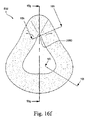
図16gから16iは、クッション性コンポーネント932(横断面の元であり、図16fで示されている)の一実施形態による様々な横断面図を示している。図19は、図20〜25の対応する横断面を有する本発明の代替の実施形態を示す。
2.2.1 Full Face Mask FIGS. 16g to 16i show various cross-sectional views according to one embodiment of the cushioning component 932 (original cross-sectional view and shown in FIG. 16f). FIG. 19 shows an alternative embodiment of the invention having the corresponding cross-section of FIGS.
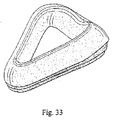
図33〜38は、インターフェース構造のさらなる好ましい実施形態を示しており、インターフェース構造は、共に成形された、またはその他の形で取り付けられたクッション性コンポーネントおよびクリップ部を含む。 FIGS. 33-38 illustrate a further preferred embodiment of an interface structure that includes a cushioning component and a clip portion that are molded together or otherwise attached.
本明細書で示されるフルフェースマスクは、幅が(ベース面の最も外側の縁部から測定して)約105〜110mm、かつ長さが120〜150mmの間であるクッション性コンポーネントを有することができることが好ましい。 The full-face mask shown herein may have a cushioning component that is about 105-110 mm wide (measured from the outermost edge of the base surface) and a length between 120-150 mm. Preferably it can be done.
鼻橋領域
図16gで示すように、鼻橋領域NBにおける横断面は、概して三角形である。鼻橋領域NBにおける横断面はまた、概して長方形、楕円形、八角形など、他の適正な形状とすることができる。さらに、鼻橋領域における横断面が、概して、丸いまたは湾曲させたコーナを有する形状を含むことも可能である。鼻橋領域における横断面はまた、不規則な形状とすることもできる。図20は、鼻橋領域に対する代替の横断面を示す。
Nasal Bridge Region As shown in FIG. 16g, the cross section in the nasal bridge region NB is generally triangular. The cross section in the nasal bridge region NB can also be other suitable shapes, such as generally rectangular, elliptical, octagonal, etc. Further, the cross section in the nasal bridge region can generally include a shape having rounded or curved corners. The cross section in the nasal bridge region can also be irregularly shaped. FIG. 20 shows an alternative cross section for the nasal bridge region.
横断面の頂点2010において半径r1が存在しており、それは、鼻橋領域NBにおける比較的小さいまたは鋭角になる半径とすることができる。例えば、半径r1は、1から4mmの間とすることができる。半径r1であるこの比較的小さいまたは鋭角となる半径は、クッション性コンポーネントが、使用時に圧縮され、かつ空気圧で膨張したとき特に、クッション性コンポーネントを、患者の目から離れるように保つ利点を提供する。半径r1である比較的小さいまたは鋭角となる半径はまた、マスクの感触がより快適に、かつ目障りにならぬようにするために、患者の皮膚とマスクの接触を最小限にすることを可能にする。
There is a radius r1 at the
図20で最もよく示されるように、概して三角形の横断面の頂点2010を、歪ませる、またはオフセットすることができる。概して三角形の横断面の頂点、またはコーナは、患者との良好な嵌合を、および/または良好なシールを促進するために丸くすることができる。このオフセットは、図20で示されており、その場合、頂点2010および中心線2015は、距離2020だけ離れている。距離2020は、患者の鼻に近い位置で約1〜2mmであることが好ましい。患者の下唇を覆うように適合された部分の周りのクッション性コンポーネントにおける同等のオフセットは、8mmであることが好ましい。患者の頬を覆うように適合された部分の周りのクッション性コンポーネントにおける同等のオフセットは、1.25mmであることが好ましい。図20は、クッション性コンポーネントの内側縁部の方向へのオフセットを示している。代替的には、頂点を歪ませることができるが、あるいはクッション性コンポーネントの外側縁部を越えることもできる。
As best shown in FIG. 20, the
さらに、クッション性部分の概して三角形の横断面はまた、3つの側面を有するものとしてさらに規定することができる。すなわち、マスクの中心へと向いている内側面と、マスクの中心から離れる方向を向いている外側面と、少なくとも部分的に、クリップ部に結合されるように適合されうるベース面とである。 Furthermore, the generally triangular cross-section of the cushioning portion can also be further defined as having three sides. That is, an inner surface that faces the center of the mask, an outer surface that faces away from the center of the mask, and a base surface that can be adapted to be at least partially coupled to the clip portion.
クッション性部分の表面の外側面は、概して、内側面よりも長くなるように適合される。こうすることにより、クッション性コンポーネントが、実際上、内側方向に回転し、曲がり、または動くことが可能になる。回転運動は、患者の皮膚とクッション性コンポーネントの間で形成されたシール面を拡大させる。クッション性コンポーネントが押下されると、患者の皮膚に対する接触領域が、頂点である最小の接触点から、クッション性コンポーネントの外側面または側面に沿って少なくとも部分的に延びるまで長くなる。 The outer surface of the cushioned portion surface is generally adapted to be longer than the inner surface. This allows the cushioning component to actually rotate inward, bend or move. The rotational movement enlarges the sealing surface formed between the patient's skin and the cushioning component. When the cushioning component is depressed, the contact area of the patient's skin increases from the smallest contact point that is the apex until it extends at least partially along the outer or side surface of the cushioning component.
例えば、ユーザの顔に接触する三角形の頂点(図58)は、頂点が、クッションコンポーネントの内側部分の方向にある場合、クッションコンポーネントが内側方向に回転し、かつヒンジ点939に関してクリップ部934周りで回転するように、クッション性コンポーネント932を撓ませる、または回転させることができる。CPAP装置からの空気圧AP(図59)は、空気圧が、クッションコンポーネントを患者の顔上でシール係合させるように、クッション性コンポーネント932の回転したセクションの背面に作用する。
For example, the apex of a triangle that touches the user's face (FIG. 58) is such that when the apex is in the direction of the inner part of the cushion component, the cushion component rotates inward and around the
マスクが顔の上に押し付けられたとき、回転作用、または回転モーメント力がまた、増加し、あるいはクッション性部分に取り付けられたクリップ部の位置決めまたは形状を支援することができる。クリップ部3234は、クッション性コンポーネントの横断面のベース面に結合できることが好ましい。クリップは、クッション性コンポーネントの外側面に近接して取り付けられ、クッション性コンポーネントの内側面に対してほとんど支持しないか、または全く支持しないことがより好ましい。クリップ部は、クッション性コンポーネントの内側面を概して支持しなくてもよいことが好ましい。
When the mask is pressed over the face, the rotational action, or rotational moment force, can also increase or assist in the positioning or shape of the clip portion attached to the cushioned portion. The
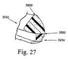
クリップ部は、その断面で見たとき段付きの外形を含むことが好ましい。図27〜32では、好ましいクリップ部が、クッション性部分に結合される。段付きの外形は、シールを提供するために、フレーム中の対応する溝、スロット、または凹部と嵌合するように適合される。この実施形態では、段の形成は、患者に使用し易くするために、クッション性コンポーネントの外側面の方向に向けられている。 The clip portion preferably includes a stepped outer shape when viewed in its cross section. 27-32, a preferred clip portion is coupled to the cushioning portion. The stepped profile is adapted to mate with a corresponding groove, slot, or recess in the frame to provide a seal. In this embodiment, the step formation is oriented toward the outer surface of the cushioning component for ease of use by the patient.
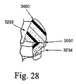
好ましくは、クリップ部は、上側面でクッション性コンポーネントに結合される。クリップ部の上側面は、クッション性コンポーネントのシールと、快適さと、かつ/またはクッション性コンポーネントの前述の回転作用とを支援するように形成することができる。図30〜31では、クリップ部の上側面は、クリップ部の短い内側面に対してクリップ部の外側面を長くすることにより、マスクの中心方向に角度が付けられている。クリップ部の上面のこの角度付けは、実際上、クッション性コンポーネントの回転を助けるまたは支援するように適合される。さらに図26〜32で示す実施形態では、クリップ部の角度付けられた上側面は、マスクの下側コーナにも含まれている。例えば、図30および31で示すように、クリップ部の上面は、下側の頬および唇領域における回転およびシールを高めるように角度が付けられている(例えば、a1およびa2は約0〜20°の間)。図32で示すように、下顎領域の上面の角度(例えば、a3は約0〜20°の間)は、例えば、製造可能であるように、下側の頬および唇領域(例えば、下唇領域)におけるものとは反対に方向付けられる(図30および31)。 Preferably, the clip portion is coupled to the cushioning component at the upper side. The upper side of the clip portion can be formed to support the sealing of the cushioning component, comfort and / or the aforementioned rotational action of the cushioning component. 30 to 31, the upper side surface of the clip portion is angled in the center direction of the mask by making the outer surface of the clip portion longer than the shorter inner surface of the clip portion. This angling of the top surface of the clip portion is effectively adapted to assist or assist in the rotation of the cushioning component. Further, in the embodiment shown in FIGS. 26-32, the angled upper side of the clip portion is also included in the lower corner of the mask. For example, as shown in FIGS. 30 and 31, the top surface of the clip portion is angled to enhance rotation and sealing in the lower cheek and lip areas (e.g., a1 and a2 are approximately 0-20 °). Between). As shown in FIG. 32, the angle of the upper surface of the lower jaw region (e.g., a3 is between about 0-20 °) is, for example, manufacturable, such as the lower cheek and lip region (e.g., lower lip region). ) In the opposite direction (FIGS. 30 and 31).
患者の鼻橋と係合するように適合された上側コーナでは、クリップ部の上面は平坦であり、マスクの中心方向に角度付けされていないことが好ましい。これは、概して、鼻の周りの領域は、患者の頬の周囲またはその付近の領域と比較して比較的長い鼻の側面に対するシール面積ほど、多くの「回転」を必要としないからである。この特徴は、図27および28で示されている。 In the upper corner adapted to engage the patient's nasal bridge, the top surface of the clip portion is preferably flat and not angled toward the center of the mask. This is because the area around the nose generally does not require as much "rotation" as the seal area for the side of the nose that is relatively long compared to the area around or near the patient's cheek. This feature is illustrated in FIGS. 27 and 28.
好ましくは、鼻橋領域はまた、ベース面に対する変更を含み、その場合、ベース面は、縮小または短くされており、それにより、鼻橋で内側に回転する発泡体材料の容積を低減する。 Preferably, the nasal bridge region also includes changes to the base surface, in which case the base surface is reduced or shortened, thereby reducing the volume of foam material that rotates inwardly at the nasal bridge.
図32は、インターフェース構造を示しており、クリップ面の上面には、マスクの中心に対して外方向に角度が付けられている。こうすることにより、上面のこの外方向に設けられた角度を含む所定の領域で「回転(roll in)」作用が低減される。概して、上面の外方向に設けられた角度は、下唇周り、または上唇周り(鼻マスク構成で)など、少ない「回転」を必要とする領域に適している。「回転」を調整するための他の方法は、クリップ部に対するクッション性コンポーネントの張出し量を変えることによる。 FIG. 32 shows the interface structure, and the upper surface of the clip surface is angled outward with respect to the center of the mask. By doing so, the “roll in” action is reduced in a predetermined area including the angle of the upper surface provided in this outward direction. In general, the angle provided in the outward direction of the top surface is suitable for areas that require less “rotation”, such as around the lower lip or around the upper lip (in a nasal mask configuration). Another way to adjust the “rotation” is by changing the overhang of the cushioning component relative to the clip portion.
図16fで示すように、クッションの内側頂点2050は、3から10mm(最も好ましくは3〜5mm)の間の曲率半径を有する。これは、クッションの内側頂点2050が曲率半径を有する図19と同様である。この半径の寸法は、耐久性に対して、より具体的にはこの領域の引裂き強度に影響する可能性がある。
As shown in FIG. 16f, the
図16gおよび20で示すように、内側縁部2090は、クッション性コンポーネントのベースから角度2100を有することができる。角度2100は、患者と接触できるクッション性コンポーネントの量に影響を与える可能性がある。例えば、図16fで示す角度2100を、図20で示す角度2100よりも大きくすることができ、したがって、図16fにおけるクッション性コンポーネントの多くが、図20のものよりも患者の顔に接触することができる。角度2100は、約90〜95度であることが好ましい。ベース面と交わる外側面または縁部の角度は、78〜83の間であることが好ましい。外側面がベース面と交わる角度は、概して、内側面とベース面の間で形成される角度未満であることが好ましい。
As shown in FIGS. 16g and 20, the
鼻橋領域の最も好ましい最大幅(ベース面に沿って測定される)は22mmであり、また鼻橋位置におけるクッション性コンポーネントの最も好ましい最大高さは約24mmである。 The most preferred maximum width (measured along the base surface) of the nasal bridge region is 22 mm, and the most preferred maximum height of the cushioning component at the nasal bridge position is about 24 mm.
下唇領域
図16gで示すように、下唇領域BLにおける横断面は、概して台形にできることが好ましい。下唇領域BLにおける横断面はまた、概して長方形、楕円形、八角形など、他の適正な形状とすることもできる。さらに、下唇領域における横断面が、概して、丸いまたは湾曲させたコーナを有する形状を含むことも可能である。下唇領域における横断面はまた、不規則な形状とすることもできる。図25は、下唇領域に対するこの特徴を横断面で示している。
Lower Lip Region As shown in FIG. 16g, the cross section in the lower lip region BL is preferably generally trapezoidal. The cross section in the lower lip region BL can also be other suitable shapes such as generally rectangular, elliptical, octagonal, etc. Further, it is possible that the cross-section in the lower lip region generally includes a shape having rounded or curved corners. The cross section in the lower lip region can also be irregularly shaped. FIG. 25 shows this feature in cross section for the lower lip region.
好ましくは、図25で示す実施形態では、頂点950は、マスクの中心方向に歪んでおり、その領域におけるクッション性コンポーネントの外側面または面は、患者の下唇領域と接触するように適合される。外側面は、上側部分と下側部分に分割されており、上側部分は、下側部分に対して少ない角度である。頂点950は、患者の下唇と下顎の下側末端との間に形成される裂溝(cleft)に置かれる、または係合するように適合される。上側部分は、下側の位置で患者の顔に係合するように適合され、裂溝から離れて延びる。それにより、下唇と下顎の下側末端との間の位置における患者の顔と、クッション性コンポーネントの外側面との間で増加したシール面を提供することができる。 Preferably, in the embodiment shown in FIG. 25, the apex 950 is distorted toward the center of the mask, and the outer surface or face of the cushioning component in that region is adapted to contact the patient's lower lip region. . The outer surface is divided into an upper part and a lower part, and the upper part has a small angle with respect to the lower part. The apex 950 is adapted to be placed or engaged in a cleft formed between the patient's lower lip and the lower end of the lower jaw. The upper portion is adapted to engage the patient's face in the lower position and extends away from the fissure. Thereby, an increased sealing surface can be provided between the patient's face at a position between the lower lip and the lower end of the lower jaw and the outer surface of the cushioning component.
図16gおよび25で最もよく示すように、患者接触面940は概して平坦であり、または鼻橋半径r1と比較したとき、より大きな半径r2を有する。この構成は、快適さを助け、また良好なシールを維持できるように、シール表面の長さを増加する。
As best shown in FIGS. 16g and 25, the
図25では、クッションの頂点における半径r2は約5mmであることが好ましい。 In FIG. 25, the radius r2 at the top of the cushion is preferably about 5 mm.
代替的に、患者接触面940は、患者の顔にまず接触し、かつ下顎のへこみに、または下唇と下顎領域の間の湾曲部にクッションを固定することのできる頂点950を有することができる。頂点950は、図16gで示された半径r2と比較したとき、比較的小さな半径r2を有することができる。半径r2は約5mmとすることができる。患者接触面940はまた、クッションを患者と係合させてシールするように、クッションを下顎に乗せるために、下顎のほぼ湾曲部に概して適合できる屈曲部または変曲部960を有することができる。この屈曲部960はまた、頂点950をクッションの中心方向内側に、かつクッションの中心から離れるように外側方向に撓ませることができ、したがって、患者の下顎または顎の動きに適応する。例えば、患者が睡眠中に自分の顎を下げる可能性があり、したがって、患者とのシールを維持するために、マスクは、患者の顎と共に動くことが可能でなくてはならない。この構成はさらに、患者の適合範囲をより大きくすることが可能である、すなわち、屈曲部960は、患者の下顎の長さと深さ、他の顔の特徴などに応じて、患者の顎上で内側方向または外側方向に撓むことができる。
Alternatively, the
さらに、図16gおよび25で示すように、クッション性コンポーネントの内壁942は、角度2150で示すように、使用時、患者の顔に対して実質的に垂直または直角に配置される。この構成は、各寸法の範囲内で、より大きな顔に対して生ずる可能性のある問題である、使用時に圧縮されたとき、発泡体クッション性コンポーネントが、患者の下唇に触れる可能性を低減する。
Further, as shown in FIGS. 16g and 25, the
ベース面に対して測定されるクッション性コンポーネントの好ましい最大幅は、概して、下唇領域に対して約35mmである。クッション性コンポーネントの好ましい最大高さは、概して、下唇領域に対して約26mmである。 The preferred maximum width of the cushioning component as measured against the base surface is generally about 35 mm for the lower lip area. The preferred maximum height of the cushioning component is generally about 26 mm relative to the lower lip area.
図25では、外側面とベース面の間で形成される角度は、約80〜90度の間であり、また内側面とベース面の間で形成される角度は、約90から100度の間である。外側面がベース面と交わる角度は、概して、内側面とベース面の間で形成される角度未満であることが好ましい。 In FIG. 25, the angle formed between the outer surface and the base surface is between about 80 and 90 degrees, and the angle formed between the inner surface and the base surface is between about 90 and 100 degrees. It is. It is generally preferred that the angle at which the outer surface intersects the base surface is less than the angle formed between the inner surface and the base surface.
鼻領域の側部
図16hで示すように、鼻側部SNにおける横断面は、概して三角形である。鼻側部領域SNにおける横断面はまた、概して、長方形、楕円形、八角形など他の適正な形状とすることができる。さらに、鼻側部領域における横断面は、概して、丸いまたは湾曲させたコーナを有する形状を含むことも可能である。鼻側部領域における横断面はまた、不規則な形状とすることもできる。図21および22は、鼻側部領域に対する代替の横断面を示す。
Side of the nose region As shown in FIG. 16h, the cross section at the nose side SN is generally triangular. The cross section in the nasal region SN can also be generally other suitable shapes such as rectangular, elliptical, octagonal, etc. Further, the cross section in the nasal region can generally include a shape having rounded or curved corners. The cross section in the nasal region can also be irregularly shaped. Figures 21 and 22 show alternative cross sections for the nasal region.
図16hは、鼻側部領域SNにおけるクッション性コンポーネントの横断面を示している。図16gで示された鼻橋領域NBと同様に、横断面は概して三角形である。しかし、三角形の横断面は、クッション性コンポーネントの内側縁部の方向に歪み、または偏っている。この構成はシールするのを助けるが、それは、内壁944が、使用時に患者の鼻の側部に当接し、それによりシール面が増加するからである。これは、図21および22で同様に示されている。
FIG. 16h shows a cross section of the cushioning component in the nasal region SN. Similar to the nasal bridge region NB shown in FIG. 16g, the cross section is generally triangular. However, the triangular cross section is distorted or biased toward the inner edge of the cushioning component. This configuration helps to seal because the
外側面は内側面より長いことが好ましい。外側面とベース面の間で形成される角度が、概して、内側面とベース面の間で形成される角度未満であることがさらに好ましい。 The outer side is preferably longer than the inner side. More preferably, the angle formed between the outer surface and the base surface is generally less than the angle formed between the inner surface and the base surface.
鼻側部領域の最も好ましい最大幅(ベース面に沿って測定される)は22mmであり、また鼻側部位置におけるクッション性コンポーネントの最も好ましい最大高さは、約24mmである。 The most preferred maximum width (measured along the base surface) of the nasal region is 22 mm and the most preferred maximum height of the cushioning component at the nasal location is about 24 mm.
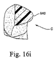
頬領域
図16iで示すように、頬Cにおける横断面は、概して、台形または三角形である。頬領域Cにおける横断面はまた、概して、長方形、楕円形、八角形など、他の適正な形状とすることもできる。さらに、頬領域における横断面が、概して、丸いまたは湾曲させたコーナを有する形状を含むことも可能である。頬領域における横断面はまた、不規則な形状とすることができる。図23および24は、頬領域に対する代替の横断面を示す。
Cheek region As shown in FIG. 16i, the cross-section at cheek C is generally trapezoidal or triangular. The cross section in the cheek region C can also be other suitable shapes, such as generally rectangular, elliptical, octagonal, etc. In addition, the cross-section in the cheek region can generally include a shape having rounded or curved corners. The cross section in the cheek region can also be irregularly shaped. Figures 23 and 24 show alternative cross sections for the cheek region.
図16iは、頬領域Cにおけるクッション性コンポーネントの横断面を示す。図示のように、クッション性コンポーネントが患者の頬に接触する接触面または頂点946は、図16gで示された下唇領域BLにおけるものと同様である。横断面は、概して三角形であり、また下唇領域BLの上面940と比較したとき、より小さな上面946を有することができる。この構成は、使用時に、患者の頬の周りでシールを行うことを支援し、インターフェース部分の快適さを高めるが、頬領域Cにおけるインターフェース部分のバルクを低減する。
FIG. 16 i shows a cross section of the cushioning component in cheek region C. FIG. As shown, the contact surface or
同様の構成が図23および24で示されている。しかし、図24で示すように、変曲部950は、内側方向に蝶番として動く、または曲がることができるように、クッションの側壁の曲率を変えている。こうすることにより、使用時に、クッションが患者の顔をシールできる能力を高めることができる。
A similar configuration is shown in FIGS. However, as shown in FIG. 24, the
クッション性コンポーネントの外側面は内側面よりも長いことが好ましい。外側面とベース面の間で形成される角度が、概して、内側面とベース面の間で形成される角度未満であることがさらに好ましい。 The outer side of the cushioning component is preferably longer than the inner side. More preferably, the angle formed between the outer surface and the base surface is generally less than the angle formed between the inner surface and the base surface.
頬領域の最も好ましい最大幅(ベース面に沿って測定される)は23mmであり、また頬領域におけるクッション性コンポーネントの最も好ましい最大高さは約24mmである。 The most preferred maximum width of the cheek region (measured along the base surface) is 23 mm and the most preferred maximum height of the cushioning component in the cheek region is about 24 mm.
さらに、クリップ部が、クッション性コンポーネントに結合される、または取り付けられたとき、クッションの頂点は、マスクの中心または中央部の方向にさらにオフセットされる。前述の実施形態では、頂点は、内側面とベース面の間で形成された点から張り出す程度にオフセットすることができる。 Further, when the clip portion is coupled or attached to the cushioning component, the apex of the cushion is further offset in the direction of the center or center of the mask. In the embodiment described above, the apex can be offset to the extent that it protrudes from the point formed between the inner surface and the base surface.
2.2.2鼻マスク
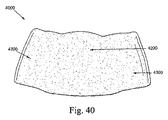
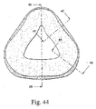
図39から47は、本発明の代替の実施形態を示す。クッションコンポーネント4000は、使用時に、患者の鼻を覆うだけであり、また鼻橋、鼻側部、頬、および/または上唇に配置される鼻マスクとして使用することができるが、患者の口を覆うことはないはずである。
2.2.2 Nasal Mask FIGS. 39 to 47 show an alternative embodiment of the present invention. The
好ましくは、これらの実施形態に関して示された鼻マスクのクッション性コンポーネントは、長さが70〜75mm(クッション性コンポーネントのベース面の最も外側縁部から測定したとき)であり、またクッション性コンポーネントの幅は、約75〜80mmであることが好ましい。 Preferably, the cushioning component of the nasal mask shown with respect to these embodiments is 70-75 mm in length (when measured from the outermost edge of the base surface of the cushioning component) and the cushioning component's The width is preferably about 75-80 mm.
鼻橋領域、鼻側部領域、および頬領域
鼻橋領域4200、鼻側部領域4300、および頬領域4400は、概して、フルフェースクッションに関して上記で述べたものと同様のものとすることができる。
Nasal Bridge Area, Nasal Side Area, and Cheek Area The
患者の鼻橋に対応するように指定された領域におけるクッション性コンポーネントの好ましい高さは、約22mmである。鼻の側部と交わるように指定された位置におけるクッション性コンポーネントの高さは、約25〜27mmである。患者の頬領域と交わるように指定された位置におけるクッション性コンポーネントの高さは、約27mmである。 The preferred height of the cushioning component in the area designated to accommodate the patient's nasal bridge is about 22 mm. The height of the cushioning component at the location designated to intersect the side of the nose is approximately 25-27 mm. The height of the cushioning component at the location designated to intersect the patient's cheek region is approximately 27 mm.
鼻側部領域におけるクッション性コンポーネントの好ましい幅は、通常約20mmである。一方、頬領域におけるクッション性コンポーネントの好ましい幅は、通常、18mmである。 The preferred width of the cushioning component in the nasal region is usually about 20 mm. On the other hand, the preferred width of the cushioning component in the cheek region is typically 18 mm.
上唇領域
図39および41で示すように、クッションコンポーネント4000は、他の領域4200の高さに対して(図41で示す側面図から見たとき)低減させた高さの窪みまたは領域を有する上唇領域4100を有することができる。この特徴は、鼻孔を予期せずに閉鎖することを回避しながら、患者の様々な上唇領域に適応することができる。発泡体材料の量を全体に低減することは、患者の危険を低下させることができる。
Upper Lip Region As shown in FIGS. 39 and 41, the
上唇領域におけるクッション性コンポーネントの好ましい幅は、通常、約16mmである。上唇領域におけるクッション性コンポーネントの幅は、10〜20mmとすることができる。上唇領域におけるクッション性コンポーネントの幅は、15〜20mmとすることができる。上唇領域におけるクッション性コンポーネントの幅は、12〜20mmとすることができる。上唇領域におけるクッション性コンポーネントの幅は、10〜15mmとすることができる。上唇領域におけるクッション性コンポーネントの幅は、10〜18mmとすることができる。上唇領域におけるクッション性コンポーネントの幅は、10〜14mmとすることができる。 The preferred width of the cushioning component in the upper lip region is typically about 16 mm. The width of the cushioning component in the upper lip region can be 10-20 mm. The width of the cushioning component in the upper lip region can be 15-20 mm. The width of the cushioning component in the upper lip region can be 12-20 mm. The width of the cushioning component in the upper lip region can be 10-15 mm. The width of the cushioning component in the upper lip region can be 10-18 mm. The width of the cushioning component in the upper lip region can be 10-14 mm.
患者の上唇に対応するように指定された領域におけるクッション性コンポーネントの好ましい高さは、約18mmである。上唇領域におけるクッション性コンポーネントの高さは、10〜20mmとすることができる。上唇領域におけるクッション性コンポーネントの高さは、10〜25mmとすることができる。上唇領域におけるクッション性コンポーネントの高さは、15〜20mmとすることができる。上唇領域におけるクッション性コンポーネントの高さは、16〜23mmとすることができる。 The preferred height of the cushioning component in the area designated to correspond to the patient's upper lip is about 18 mm. The height of the cushioning component in the upper lip region can be 10-20 mm. The height of the cushioning component in the upper lip region can be 10-25 mm. The height of the cushioning component in the upper lip region can be 15-20 mm. The height of the cushioning component in the upper lip region can be 16-23 mm.
適合範囲
様々な人々の顔の広範囲な寸法および形状のために、最も広範囲の患者に適合することが必要な最小数のマスク形状を決定することは、マスク設計者にとって絶え間ない挑戦である。理想的な一形態では、単一のマスクがすべての患者に適合することになる。
Range of Fit Due to the wide range of dimensions and shapes of various people's faces, it is a constant challenge for mask designers to determine the minimum number of mask shapes that need to fit the widest range of patients. In one ideal form, a single mask will fit all patients.
本発明によるマスクアセンブリは、改良された適合範囲を提供する。これは、所与の形状に対して、広範囲な顔の解剖学的構造に対してシールを行うさらに解剖学的に中立な幾何形状と、より快適で可撓性のある材料とを組み合わせることにより達成されることが好ましい。 The mask assembly according to the present invention provides an improved fit range. This is by combining a more comfortable and flexible material with a more anatomically neutral geometry that seals against a wide range of facial anatomy for a given shape. It is preferably achieved.
選択されたクッション形状の多様性、したがって、その適合範囲性能はまた、クッションにより示される「ホバークラフト(hovercraft)」挙動により向上される。この文脈中では、「ホバークラフト」挙動は、マスクの空洞中の空気圧が、外側環境の空気圧よりも大きく、それにより、マスクを、装着者の顔の上で浮上させることができる場合、マスクの空洞中の空気圧により概して規定される。圧力シールは、クッション性コンポーネントにより形成されることが好ましい。この特徴は、マスクを適合させることの容易さおよび速度を向上させることができる。 The variety of cushion shapes selected, and therefore their coverage performance, is also improved by the “hovercraft” behavior exhibited by the cushion. In this context, the “hovercraft” behavior is that if the air pressure in the mask cavity is greater than the air pressure in the outside environment, thereby allowing the mask to float above the wearer's face, It is generally defined by the air pressure inside. The pressure seal is preferably formed by a cushioning component. This feature can improve the ease and speed of adapting the mask.
空気で加圧されたとき、クッション材料は、他の知られたクッション材料と比較して、特別の伸長性を有する。発泡体材料中の柔軟で可撓性のある気泡は、膨張したとき、有効に伸長し、材料に拡大する自由度を与えることができる。これは、空気圧で膨張したとき、拡大し、かつ顔の解剖学的構造に合わせて変形できることにより、例えば、シリコーンなどの当技術分野で知られた他のクッション材料に対して、クッション材料は、特別な範囲の順応性を有することを可能にする。これはまた、一部には、気道への正の加圧を提供している空気と直接連通する拡大可能な連続気泡構造を組み合わせることにより達成される。顔の皮膚との間で加圧された空気の微細な層を形成するのは、シール材料を通る空気の流れであり、またこのホバークラフト効果を可能にし、それにより顔に適合させることを容易にするのは、クッション材料の可撓性のある性質のためである。シリコーンよりも粘着性の少ない発泡体がまた、容易で、迅速であり、かつ快適な適合性を達成することに著しい利点を有する。 When pressurized with air, the cushioning material has a particular extensibility compared to other known cushioning materials. Soft and flexible bubbles in the foam material can effectively stretch when expanded and give the material freedom to expand. This allows the cushion material to expand and deform to the facial anatomy when inflated with air pressure, so that the cushion material, for example, relative to other cushion materials known in the art, such as silicone, It makes it possible to have a special range of adaptability. This is also achieved in part by combining an expandable open cell structure in direct communication with air providing positive pressure to the airway. It is the flow of air through the sealing material that forms a fine layer of pressurized air with the facial skin and also enables this hovercraft effect, thereby making it easier to adapt to the face This is due to the flexible nature of the cushion material. Foams that are less tacky than silicone also have significant advantages in achieving easy, quick and comfortable fit.
2.3製作方法
以下の製作方法は、様々な顔形状に必要となりうる、ある範囲の形状および横断面を作成するために使用することができる。クッション性コンポーネントは、スキンが除去された発泡体から作ることが好ましいので、部品を作るために1つまたは複数の切断工程を使用することができ、このような切断工程は、打抜きおよび/または機械加工などを含む。代替的に、クッション性コンポーネントは、発泡体コンポーネント上のスキンを最小化するために工程中で行われる処置を用いて成形することができるが、あるいはスキンは、例えば、機械加工などの後処理で、成形されたコンポーネントからその後に除去される。好ましくは、本明細書で述べる実施形態で使用される発泡体材料は、連続気泡発泡体および独立気泡発泡体とすることができる。使用される発泡体材料は連続気泡発泡体とすることができる。使用される発泡体材料は独立気泡発泡体とすることもできる。
2.3 Manufacturing Methods The following manufacturing methods can be used to create a range of shapes and cross sections that may be required for various face shapes. Since the cushioning component is preferably made from foam with the skin removed, one or more cutting processes can be used to make the part, such cutting processes can be stamped and / or machined Including processing. Alternatively, the cushioning component can be molded using a procedure performed in the process to minimize the skin on the foam component, or the skin can be post-processed, eg, machining. And subsequently removed from the molded component. Preferably, the foam materials used in the embodiments described herein can be open cell foams and closed cell foams. The foam material used can be an open cell foam. The foam material used can also be a closed cell foam.
2.3.1打抜き
図4a〜4gで示す例示の実施形態では、発泡体クッションコンポーネント232の内側面および外側面は共に打ち抜かれる。これにより、通常、概して、まっすぐな切断縁部が得られる。これらの実施形態におけるクッションは、概して、長方形の横断面を有することができ、その場合、上面は、使用時に、患者の顔に対して、概して実質的に平行になり、また内側および外側の表面は、使用時に、患者の顔に対して、概して直角となる。例えば、シムを使用して、非長方形の横断面を作成するように、さらなる処理ステップを使用して発泡体を打ち抜くことも可能である。その場合、発泡体の平坦なシートからのクッションコンポーネントの打抜きにより、平坦な背面のクッションコンポーネントが得られ、それは、その後に、例えば、接着などで組み立てられるクリップの形をとることができる。したがって、発泡体クッションは、その最終的な意図する形状へと変形される。
2.3.1 Stamping In the exemplary embodiment shown in FIGS. 4a-4g, the inner and outer surfaces of the
例えば、伸長または変形させることなく、湾曲したクリップの形状に適合する湾曲した背面のクッションを作成するために、クッションコンポーネントは、平坦なシートではなく湾曲した形状に切断された発泡体シートから打ち抜くことができる。湾曲したシートは、輪郭切断(contour cutting)と呼ばれる知られた工程から形成することができ、その場合、発泡体ブロックは、切断工程中、位置と方向を変化させる揺動刃(oscillating blade)へと送られることにより、湾曲したシートへと切断される。 For example, to create a curved back cushion that conforms to the shape of a curved clip without stretching or deforming, the cushion component is stamped from a foam sheet cut into a curved shape rather than a flat sheet. Can do. Curved sheets can be formed from a known process called contour cutting, in which case the foam block is moved to an oscillating blade that changes position and orientation during the cutting process. Is cut into a curved sheet.
打抜きに加えて、または代替として、例えば、図9aから12fで示すものなど、クッション性コンポーネントを、AU2008904769およびAU2008904778で述べられた技法を用いて3次元形状または幾何形状へと切断することができる。 In addition to or as an alternative, cushioning components, such as those shown in FIGS. 9a to 12f, for example, can be cut into a three-dimensional shape or geometry using the techniques described in AU2008904769 and AU2008904778.
図9aから9dは、発泡体クッションコンポーネント432およびクリップ部434を含む発泡体ベースのインターフェース構造430を示している。外壁400は、設計に組み込まれた輪郭と湾曲を含むことができる。内側の患者に接触する壁(または開口部)402は、当技術分野で知られるように打ち抜くことができる。こうすることにより再度、まっすぐな切断縁部が通常得られる(例えば、図9bおよび9dを参照のこと)。
FIGS. 9 a to 9 d show a foam-based
図10aから10cは発泡体クッションコンポーネント332およびクリップ部334を含む発泡体ベースのインターフェース構造330を示しており、クッションコンポーネント332は、例えば、クッションコンポーネントの頬領域に沿った隆起部350、クッションコンポーネントの鼻橋領域に沿った湾曲部352など、湾曲部または隆起部を有する局所化された領域を含む。さらに、クッションコンポーネント332は、クッションコンポーネントの下顎領域に沿って輪郭が付けられている。まっすぐに打ち抜かれた内側および外側縁部は、前の実施形態と同様に、使用時、患者の顔に対して直角のままである。
FIGS. 10a to 10c show a foam-based
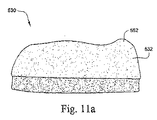
図11aから11cは、発泡体ベースのインターフェース構造530を示しており、その場合、鼻橋におけるクッションコンポーネント532の局所化された領域552を、例えば、湾曲させた面で形成されるなど、高くしている。
FIGS. 11a to 11c show a foam-based
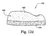
図12aから12fは、発泡体ベースのインターフェース構造630が、発泡体クッションコンポーネント632およびクリップ部634を含む他の実施形態を示しており、その場合、発泡体クッションコンポーネント632は、当技術分野で知られた方法を用いて切断された発泡体の厚板(slab)を含む。この工程は、クッションコンポーネントの外壁600を切断し、次いで、クッションコンポーネントの内側の患者接触壁(または開口部)602を切断するために繰り返すことができる。
FIGS. 12a to 12f show another embodiment in which the foam-based
3.クリップコンポーネント
3.1材料
クッション/フレーム用コンポーネントは、クッション性コンポーネントよりも優れた構造的完全性を有する材料から作ることができる。好ましい実施形態では、クリップは、クッション性コンポーネント用に使用される発泡体よりも高い硬度、高い密度、および低い通気性を有するポリウレタン発泡体から作られる。クリップ、すなわちクッション/フレーム用コンポーネントは、スキンを有する、硬度、密度が高く、低い通気性の発泡体を生成する型により形成することができる。代替の好ましい実施形態では、クリップは、非発泡のポリマー、例えば、(これだけに限らないが)ナイロン、ポリカーボネート、ポリプロピレンから構成することもできる。
3.Clip component
3.1 Materials Cushion / frame components can be made from materials that have better structural integrity than cushioning components. In a preferred embodiment, the clip is made from a polyurethane foam that has a higher hardness, higher density, and lower breathability than the foam used for the cushioning component. The clip, i.e. cushion / frame component, can be formed by a mold having a skin that produces a hard, high density, low breathable foam. In an alternative preferred embodiment, the clip may be constructed from a non-foamed polymer, such as (but not limited to) nylon, polycarbonate, polypropylene.
好ましくは、クリップ部またはクリップコンポーネントは、それが接続される、または固定されるマスクのフレーム部と比較して、硬度を下げた、または可撓性を高めたものとすることができる。 Preferably, the clip portion or clip component may have reduced hardness or increased flexibility compared to the frame portion of the mask to which it is connected or secured.
3.2形状
クリップ934は、図13で概略的に示され、また図15a〜15eでより詳細に示されている。クリップ934は、概して、フレームと位置が合うような形状をしている。しかし、クリップ934の全体的な湾曲は、嵌め合わされるフレームに合うように変えることができる。クリップの全体的な湾曲はまた、クッションコンポーネントを形成するために使用することができる。クッションコンポーネントは可撓性のある発泡体から作られるので、共に結合されると、容易にクリップの形状に適合することになる。それが利点を有することがある場合の例は、クッションコンポーネントが(前に述べたように、平坦な発泡体から)平坦な背面を有するように作成される場合であり、クリップに組み立てる(例えば、接着されて)ことによりその最終形状が与えられ、それにより、クッションにその意図された(例えば、湾曲させた)形状が与えられる。
3.2
クリップを平坦に作ることもできる。したがって、クッションはまた、クリップに適合するように平坦な背面を備えて作ることもできる。インターフェース構造(クリップとクッションの組合せ)の全体的な意図する形状は、したがって、代替的に、平坦なクリップおよびクッションが変形され、湾曲したフレーム中に保持されることにより達成することもできる。この実施形態は、クリップを平坦に製作することを可能にするが、それは、取り扱いの容易さ、および製造中の位置合わせ、パッケージング、および移送を含むいくつかの利点を有することができる。したがって、クリップは、例えば、平坦なシート材料からの打抜きなど、代替的な方法により形成することができる。 Clips can be made flat. Thus, the cushion can also be made with a flat back to fit the clip. The overall intended shape of the interface structure (combination of clip and cushion) can therefore alternatively be achieved by the flat clip and cushion being deformed and held in a curved frame. While this embodiment allows the clip to be made flat, it can have several advantages including ease of handling and alignment, packaging, and transport during manufacture. Thus, the clip can be formed by alternative methods such as, for example, stamping from a flat sheet material.
クリップはまた、湾曲させることもできる。これは、湾曲した形状へと直接成形すること、湾曲した(輪郭切断された)シートから打ち抜くこと、または熱成形可能な材料から打ち抜かれた平坦なクリップを熱成形することを含むいくつかの手段により達成することができる。クリップを湾曲させることにより、湾曲したフレームへの位置合わせおよび組立てを容易にすることができ、ならびにクッションが、平坦な背面を有するものが得られる工程から製作される場合、クッションに湾曲した形状を与えることができる。 The clip can also be curved. This includes several means including directly forming into a curved shape, stamping from a curved (contour cut) sheet, or thermoforming a flat clip stamped from a thermoformable material Can be achieved. Curving the clip can facilitate alignment and assembly to the curved frame, and if the cushion is made from a process that results in one having a flat back, the curved shape of the cushion Can be given.
好ましい実施形態では、クリップは、成形されたポリウレタンから作られる。クッション接触面935は、クッションの下側に連続的に結合してシールすることができるように、概して、滑らかである。クッション接触面935は、クリップをフレームに位置合わせできるようにするリップ935aを有する。
In a preferred embodiment, the clip is made from molded polyurethane. The
フレーム接触面937は、フレームと係合するその表面から突き出た3つの位置合わせタブ938を有する。患者が、インターフェース構造を固定構造と位置合わせするのを支援するためには、任意の数の位置合わせタブ938がありうる。クリップは、クリップをフレームと係合させるために位置合わせタブ938を有する必要がないことも理解されたい。
クリップはまた、フレームに対してインターフェース構造を保持するのを支援するために、フレームに係合させる機構を組み込むように作ることもできる。例としては、これだけに限らないが、表面の粗化、リブ、切込み、スナップなどが含まれる。 The clip can also be made to incorporate a mechanism that engages the frame to help retain the interface structure relative to the frame. Examples include, but are not limited to, surface roughening, ribs, cuts, snaps, and the like.
3.3製造方法
クリップコンポーネントは、次に述べるように、別個に製作することができるが、あるいは本明細書で後に述べるように、インサート成形することもできる。
3.3 Manufacturing Method The clip component can be fabricated separately as described below, or it can be insert molded as described later in this specification.
例として、図18aから18cは、それ自体でクリップ部を成形するためのツールを示しており、クリップ部は、その後、例えば、クリップとクッションコンポーネントの間で、接着剤により、または単に粘着させることにより、クッションコンポーネントに取り付けることができる。図示のように、ツールは、上ハーフ(top half)1560および下ハーフ(bottom half)1565を含み、それらは、共に結合されてクリップ部を形成するように適合される。図18bで示すように、ツールは、上ハーフ1560と下ハーフ1565の間で湾曲した分割線PLを設けている。
As an example, FIGS. 18a to 18c show a tool for molding a clip part by itself, which can then be glued, for example, with an adhesive or simply between the clip and the cushion component Can be attached to the cushion component. As shown, the tool includes a
下ハーフ1565は、クリップ部を形成することになる材料(例えば、発泡混合物)を受け入れるように適合されたキャビティ1567を含む。さらに、下ハーフ1565の中心セクション1568は、成形後に手動の押出し機構として働く別個のインサートを収容する。上ハーフ1560は、クッションコンポーネントとインターフェースする、または結合するためのクリップ部の側面を形成することになる表面1562を設けている。
ツールの上ハーフ1560および下ハーフ1565は、クリップ部がツールに付着しないように、クリップ部をツールから取り出すことを容易にするように構成され、かつ/または配置される。例えば、上ハーフ1560および下ハーフ1565は、成形材料(例えば発泡混合物)を除去できる材料から構成することができる(例えば、高密度ポリプロピレン、シリコーン)。代替的には、離型剤(例えば、ワックス)を、離型を容易にするために、上下ハーフに提供することもありうる。
The
代替的に離型を支援するものは、ツールに内張りされ、成形後、容易にクリップ材料から解放させる離型フィルムとすることができる。好ましい実施形態では、離型フィルムを、インターフェース構造のためのパッケージングとして、全体で、または一部を二重にすることができ、したがって、製品は、すでに包装された状態で成形工程を出ることになる。他の実施形態では、クリップは、製造工程中に、離型させるための部品を把持することを容易にするタブを、1箇所またはいくつかの場所に含む。このタブ構造はまた、マスクアセンブリのユーザに対して、組立を行うための位置合わせ構造と、分解するための把持構造とにより倍化されうる。 Alternatively, the release aid can be a release film that is lined on the tool and can be easily released from the clip material after molding. In a preferred embodiment, the release film can be doubled in whole or in part as packaging for the interface structure, so that the product exits the molding process already packaged. become. In other embodiments, the clip includes tabs at one or several locations that facilitate gripping the part to be released during the manufacturing process. This tab structure can also be doubled for the mask assembly user by an alignment structure for assembly and a gripping structure for disassembly.
他の実施形態では、クリップは、インターフェース構造に対する寿命インジケータを含むタブ構造を含むことができる。 In other embodiments, the clip can include a tab structure that includes a life indicator for the interface structure.
4.サブアセンブリ
4.1相対位置
本発明の実施形態によれば、クリップ部およびクッションコンポーネントのある範囲の構成を提供することができる。例えば、クリップ部の幅は、クッションコンポーネントの最大幅と一致する、または未満であることが好ましく、クリップ部の横断面の幅が、クッションコンポーネントの横断面の幅未満とすることができる。異なる相対的な幅を有するこれらの異なる構成では、クリップ部は、クッションコンポーネントに対する異なる形態の支持を提供する。
4. Subassembly
4.1 Relative Position According to an embodiment of the present invention, a range of configurations of the clip portion and the cushion component can be provided. For example, the width of the clip portion preferably matches or is less than the maximum width of the cushion component, and the width of the cross section of the clip portion can be less than the width of the cross section of the cushion component. In these different configurations with different relative widths, the clip portions provide different forms of support for the cushion component.
クリップ部の横断面の幅が、クッションコンポーネントの横断面の幅未満である場合、クリップ部およびクッションコンポーネントは、以下のように構成することができる。すなわち、(i)クリップ部およびクッションコンポーネントの外周が位置合わせされる(クリップ部の堅さを隠して、クッションコンポーネントにおける望ましい動きの自由度を提供する)、(ii)クリップ部およびクッションコンポーネントの内周が位置合わせされる、または(iii)クリップ部およびクッションコンポーネントの内周または外周のいずれも位置合わせされない。 When the width of the cross section of the clip portion is less than the width of the cross section of the cushion component, the clip portion and the cushion component can be configured as follows. (I) the outer peripheries of the clip part and the cushion component are aligned (hiding the rigidity of the clip part to provide the desired freedom of movement in the cushion component); (ii) the inner part of the clip part and the cushion component The circumference is aligned, or (iii) neither the clip portion nor the inner or outer periphery of the cushion component is aligned.
同様に、クリップ部の幅が、クッションコンポーネントの幅を超える場合、クリップ部およびクッションコンポーネントは以下のように構成することができる。すなわち、(i)クリップ部およびクッションコンポーネントの外周が位置合わせされる、(ii)クリップ部およびクッションコンポーネントの内周が位置合わせされる、または(iii)クリップ部およびクッションコンポーネントの内周または外周のいずれも位置合わせされない。 Similarly, when the width of the clip portion exceeds the width of the cushion component, the clip portion and the cushion component can be configured as follows. That is, (i) the outer periphery of the clip part and the cushion component is aligned, (ii) the inner periphery of the clip part and the cushion component is aligned, or (iii) the inner periphery or outer periphery of the clip part and the cushion component Neither is aligned.
クリップ部の幅がクッションコンポーネントの幅未満であり、かつクリップ部の外周がクッションコンポーネントと位置合わせされる場合、クッションコンポーネントは、クッションコンポーネントに隣接した、または支持するクリップ部を有する領域にではなく、隣にクリップ部を有しない領域または方向に撓むようにさらにできることが好ましい。例えば、クッションコンポーネントがクリップ部から張り出している場合、クッションコンポーネントのその張り出している領域は、より多くの動く自由度を有する。この構成は、より快適であり、人間の様々な幾何形状に適合することがさらに可能になり、また顔に対してクッションコンポーネントをシールするための正しい方向を提供することができる。 When the width of the clip portion is less than the width of the cushion component and the outer periphery of the clip portion is aligned with the cushion component, the cushion component is not in an area that has a clip portion adjacent to or supporting the cushion component, It is preferable that it can further bend in a region or direction that does not have a clip portion next to it. For example, if the cushion component overhangs from the clip portion, that overhanging region of the cushion component has more freedom of movement. This configuration is more comfortable, can further adapt to various human geometries, and can provide the correct orientation for sealing the cushion component against the face.
クリップ部は、クッション性コンポーネントのベース面でクッション性コンポーネントに結合されることが好ましい。クリップ部を、ベース面の外側の末端(マスクの周囲に対して)を支持するように、かつベース面の内側の末端を支持しない、またはほとんど支持しないようにすることも好ましいはずである。 The clip portion is preferably coupled to the cushioning component at the base surface of the cushioning component. It would also be preferable to support the clip portion so that it supports the outer end of the base surface (relative to the periphery of the mask) and does not support or hardly supports the inner end of the base surface.
呼吸マスクの一部として使用される場合、クッションコンポーネントの内側部分がクリップ部から張り出すことが好ましい可能性がある。この構成では使用時に、患者の顔が、柔軟なクッションコンポーネントの支持されていない内側縁部と係合することができ、それを曲げて、個々の患者の形に適応させる。マスクが患者の顔に係合したとき、クッション性コンポーネントは、圧力が患者の顔の方向にマスクに加えられると、マスクの中心方向内側に回転することができる。 When used as part of a respiratory mask, it may be preferable for the inner portion of the cushion component to overhang from the clip portion. In this configuration, in use, the patient's face can engage the unsupported inner edge of the flexible cushion component and bend it to adapt to the individual patient's shape. When the mask engages the patient's face, the cushioning component can rotate inwardly in the center of the mask when pressure is applied to the mask in the direction of the patient's face.
図7aは、鼻橋領域における図4eで示されたインターフェース構造230のフレーム側からの正面の細部を示す。図7bの横断面で示すように、クリップ部234の幅w2は、クッションコンポーネント232の幅w1未満であること、ならびにクリップ部234およびクッションコンポーネント232の外周が位置合わせされていることは明らかである。この構成の利点は、図7cで示されており、使用時に、鼻が、片持ち梁状に、ならびに圧縮されるように、矢印で示された方向へ、クッションコンポーネント232の内周を押すことができる。図8は、マスクフレーム20のチャネル22内に受け入れられたインターフェース構造230のクリップ部234を示す横断面である。
FIG. 7a shows a front detail from the frame side of the
この構成は、従来技術のクッション(図6aおよび6bで示すLifecare(商標)マスクなど)とは反対のものであり、従来技術のクッションは、クッションCの内周がフレームFに当接しており、したがって、内側方向に自由に動くことはなく、圧縮するだけである。 This configuration is the opposite of the prior art cushion (such as the LifecareTM mask shown in FIGS. 6a and 6b), the prior art cushion has the inner circumference of the cushion C in contact with the frame F, Therefore, it does not move freely in the inward direction, but only compresses.
図26〜32は、本発明の代替の実施形態を示す。図26は、後に図27〜32で示される横断面を示している。クッションコンポーネント3232は、クリップコンポーネント3234に取り付けることができる。クッションコンポーネント3232は、図19〜25で示されたものと同様でありうる。クリップコンポーネント3234は、クッションコンポーネント3232に取り付けられる上面3500を有することができる。上面3500は、図27、28、および29で示すように、使用時、または組み立てられたとき、概して水平でありうる。さらに、これは、クッションコンポーネント3232の頂点3600に対する接線を、概して、上面3500に平行に配置することができる。代替的に、図30、31、および32で示すように、上面3500は、患者の顔のさらに中心方向に向けてクッションを角度付けするために、クッションの内側部分に向けて内側に概して湾曲させる、または角度を付けることができる。したがって、頂点3600に対する接線は、上面3500に対して平行ではなくなる可能性がある。実施形態では、上面3500は、より狭い、浅い顔を有する患者に適合するために、1つまたは複数の選択領域、例えば、下側の頬領域または下顎領域で角度を付けることができる(図30〜32を参照)。
Figures 26-32 illustrate an alternative embodiment of the present invention. FIG. 26 shows the cross-section shown later in FIGS. The
実施形態では、図27〜32で示すように、クッションコンポーネントの外側縁部は、例えば、製造可能性のために、クリップコンポーネントからわずかに張り出す(例えば、1mmの張出し)ことができる。 In embodiments, as shown in FIGS. 27-32, the outer edge of the cushion component can overhang slightly from the clip component (eg, a 1 mm overhang), eg, for manufacturability.
4.2接着剤
ポリウレタン熱溶融型接着剤またはシアノアクリレートを用いて、2層(すなわち、クッションコンポーネントおよびクリップ部)を互いに接着することができる。
4.2 Adhesive Two layers (ie cushion component and clip part) can be glued together using polyurethane hot melt adhesive or cyanoacrylate.
代替の実施形態では(図で示されていない)、クッション部分は、フレーム上に直接接着することもできる。 In an alternative embodiment (not shown), the cushion portion can also be glued directly onto the frame.
4.3インサート成形
本発明の実施形態による製造工程では、クッション性コンポーネントをクッション/フレーム用コンポーネントに組み立てるために、インサート成形を使用することができる。この手法の利点は、接着などの他の工程と比較したとき、低コストであることを含む。
4.3 Insert Molding In the manufacturing process according to embodiments of the present invention, insert molding can be used to assemble the cushioning component into a cushion / frame component. The advantages of this approach include low cost when compared to other processes such as gluing.
図17aから17hは、本発明の実施形態によるインターフェース構造を製造するためのツールおよび製造工程を示す。 Figures 17a to 17h illustrate tools and manufacturing processes for manufacturing an interface structure according to an embodiment of the present invention.
図17aで最もよく示すように、ツールは、発泡体のスラブ材から切断することのできるクッション性コンポーネントを受け入れるように適合された第1の部分1060と、クッション/フレーム用コンポーネントを形成することになる発泡混合物を受け入れるように適合された第2の部分1065とを含む。
As best shown in FIG. 17a, the tool forms a cushion / frame component with a
ツールの第1の部分1060は、一定の位置に保持するためにクッション性コンポーネントに真空を加えることができる。例えば、図17aで示すように、クッション性コンポーネントを受け入れるキャビティの壁は、複数の開口部1062を含み、またクッション性コンポーネントがキャビティ中に吸引されうるように、第1の部分1060の側壁中の開口部1063に対して真空が加えられる。第1の部分1060は、クッション性コンポーネントと締り嵌めを行うような寸法とすることができる。
The
ツールの第1および第2の部分1060、1065は、クッション性コンポーネントとクッション/フレーム用コンポーネントの間で、互いに接着されるように、接触する領域が存在するように構成される。
The first and
ツールの少なくとも第2の部分は、普通であればツールに付着することになるクッション/フレーム用コンポーネントの離型を容易にするように構成される、かつ/または配置される。これは、発泡体を除去することのできる材料から構成されたツールを用いることにより達成されることが好ましい(例えば、高密度ポリプロピレン、シリコーン)。代替的に、ワックス(例えば、生体適合性問題を示すことのない作用薬)などの適切な離型剤を使用できる場合、鋼またはアルミニウムのツールを使用することもできる。 At least a second portion of the tool is configured and / or arranged to facilitate release of the cushion / frame component that would otherwise adhere to the tool. This is preferably accomplished by using a tool constructed from a material that can remove the foam (eg, high density polypropylene, silicone). Alternatively, steel or aluminum tools can be used if a suitable release agent such as a wax (eg, an agent that does not exhibit biocompatibility problems) can be used.
図17aで最もよく示されている例示の実施形態では、第2の部分1065は、互いに取外し可能に取り付けられた3つの部分、すなわち、内側部分1066(1)、外側部分1066(2)、およびリング部分1066(3)を含む。
In the exemplary embodiment best shown in FIG. 17a, the
本発明の実施形態によるインサート成形の製造工程を、次に、より詳細に述べるものとする。 The manufacturing process of insert molding according to an embodiment of the invention will now be described in more detail.
図17aは、互いに分離されたツールの第1および第2の部分1060、1065を示している。図17bおよび17cでは、クッション性コンポーネント1032が、ツールの第1の部分1060中に置かれている。クッション性コンポーネント1032は、真空により第1の部分1060中の一定の位置に保持することができ、また真空により、クッション性コンポーネントに湾曲を与えることができる。これは、クッションが、平坦な背面の幾何形状を与える工程から作られた場合に必要となりうる。クッション性コンポーネント1032を配置することは、手動で、または自動で行うことができる。例えば、クッション性コンポーネント1032は、真空を用いて、第1の部分1060中に吸引することができる。
FIG. 17a shows the first and
図17dでは、クッション/フレーム用コンポーネント1034を形成するためにポリウレタンの混合物(例えば、発泡体またはエラストマー)が調製され、その高密度の混合物が、ツールの第2の部分1065へと注入される。クッション/フレーム用コンポーネント1034のための混合物の注入は、手動で、または自動で行うことができる。クッション/フレーム用コンポーネント1034が発泡体から作られる場合、第2の部分1065のキャビティは、部分的に(例えば、25%)充填されるだけであり、発泡工程中、それは拡大して、空間を満たし、接着されるクッション性コンポーネントと接触状態になる。
In FIG. 17d, a polyurethane mixture (eg, foam or elastomer) is prepared to form the cushion /
図17eでは、ツールの第1および第2の部分1060、1065が共にクランプされ、または閉じられて、クッション/フレーム用コンポーネントの発泡反応がツール中で進行できるようにする。すなわち、クッション/フレーム用コンポーネント1034に対する発泡が成長し、発泡体クッション性コンポーネント1032に化学的に結合または接着されうる。クリップ材料の選択は、結合または接着工程を促進することができる。好ましい実施形態では、クリップおよびクッションは共に、2つのコンポーネント間の理想的な結合の完全性のためにポリウレタン材料から作られる。さらに、クッションコンポーネントが、規則的な、一様な、粗い、不規則な、または非一様な気泡構造を有する場合、クリップコンポーネントは、クッションコンポーネントの気泡構造中のギャップ中に入り込み、コンポーネント間で小さな機械的結合を形成することができる。
In FIG. 17e, the first and
クッション/フレーム用コンポーネント1034が硬化されたとき、真空の第1の部分および第2の部分は、図17fで示すように分離される。図17gでは、第2の部分1065の底部にあるリング部分1066(3)が除去され、内側部分1066(1)が押し出されて、クッション/フレーム用コンポーネント1034を離型させる。図17hは、クッション性コンポーネント1032がクッション/フレーム用コンポーネント1034に接着された状態でツールから除去されて、得られたインターフェース構造1030を示している。好ましい実施形態では、クッションコンポーネントは、ツールの上ハーフに挿入されたときは元々平坦であり、インサート成形工程中に湾曲したクリップに結合される。次いで、得られたインターフェース構造は、意図された湾曲した形状になる。
When the cushion /
代替の実施形態では、クッションおよびクリップは平坦に作られるが、クッションは、装着されたとき、顔に適切に適合するための湾曲を必要としない十分な深さで製作され、むしろ、クッションの発泡体の柔軟さおよび深さにより、顔の形状に合わせて適切に変形する。 In an alternative embodiment, the cushion and clip are made flat, but the cushion is made deep enough that, when worn, does not require curvature to properly fit the face, rather the foam of the cushion Depending on the flexibility and depth of the body, it deforms appropriately according to the shape of the face.
他の代替的な構成では、発泡混合物を加える前に、フィルムを、ツールの第2の部分に加えることができる。このフィルムは、普通であれば付着するクッション/フレーム用コンポーネントを除去するのを容易にするように構成することができる。フィルムは、インターフェース構造のためのパッケージングを形成するために使用することもできる。 In another alternative configuration, the film can be added to the second part of the tool prior to adding the foam mixture. The film can be configured to facilitate removal of otherwise adhering cushion / frame components. The film can also be used to form packaging for the interface structure.
実施形態では、インターフェース構造のクリップ部は、クッションコンポーネントよりもさらに剛性があり、かつ高密度の発泡体から構成することができる。例えば、クリップ部は、窒素で発泡されたポリエチレン、または微細な気泡構造を有する何らかの他の生体適合性のある発泡体から形成することができる。代替的には、クリップ部は、何らかの他のポリマーまたはゴムから作ることもできる。実施形態では、クリップ部は、クッション/フレーム係合機構を形成するように、かつクッションコンポーネントに対する構造的な支持を形成するように適合される。 In an embodiment, the clip portion of the interface structure is more rigid than the cushion component and can be constructed from a high density foam. For example, the clip portion can be formed from polyethylene foamed with nitrogen, or some other biocompatible foam having a fine cellular structure. Alternatively, the clip portion can be made from some other polymer or rubber. In embodiments, the clip portion is adapted to form a cushion / frame engagement mechanism and to provide structural support for the cushion component.
好ましくは、クッション性コンポーネントは、クリップ部よりも剛性が低く、堅さが少なく、またはより可撓性があるが、クリップ部は、次いで、マスクのフレームよりも剛性が低く、堅さが少なく、またはより可撓性がある。フレームが、マスクのインターフェース構造に対して形状を付与することが好ましく、その場合、インターフェース構造は、フレームよりも全体的に比較的可撓性があり、剛性が低い。このような特徴は、快適さを付加し、さらに患者またはユーザが、インターフェース構造を容易に置き換えられるようになる。インターフェース構造に対するさらなる改良は、その形状および構成を使い捨てされるように適合させることである。 Preferably, the cushioning component is less stiff and less stiff or more flexible than the clip portion, but the clip portion is then less stiff and less stiff than the mask frame, Or more flexible. The frame preferably imparts a shape to the interface structure of the mask, in which case the interface structure is generally more flexible and less rigid than the frame. Such features add comfort and also allow the patient or user to easily replace the interface structure. A further improvement to the interface structure is to adapt its shape and configuration to be disposable.
例えば、図13は、発泡体ベースのクッションコンポーネントとインターフェースするための側面735と、マスクフレームとインターフェースするための側面737とを含むクリップ部734を示す。この実施形態では、クリップ部734は、スキンを有する発泡体から構成され、また成形により形成することができる。クリップ部734の発泡体は、クッションコンポーネントの発泡体よりも硬度を高く、またはより高密度にすることができる。代替的には、より密度の高い、またはより硬度のある発泡体は、例えば、打抜き、機械加工、および/またはAU2008904769およびAU2008904778に記載の方法など、切断することにより形成することができる。
For example, FIG. 13 shows a
この構成は、患者の顔に係合するように適合されたクッションコンポーネントと、マスクフレームとインターフェースするように適合されたクリップ部とを備える一体型のインターフェース構造を提供する。 This configuration provides a unitary interface structure comprising a cushion component adapted to engage the patient's face and a clip portion adapted to interface with the mask frame.
一形態では、発泡体ベースのクッション、シリコーンベースのクッション、およびジェルベースのクッションの組から選択された少なくとも2つの異なる形態のインターフェース構造を含むマスクシステムを提供することができる。 In one form, a mask system can be provided that includes at least two different forms of interface structures selected from a set of foam-based cushions, silicone-based cushions, and gel-based cushions.
図14aから16iは、クッション性コンポーネント932と、クッション性コンポーネント932に提供されるクッション/フレーム用コンポーネント、すなわち、クリップ部934とを含むインターフェース構造930を示している。図14aから14fは、クッション/フレーム用コンポーネント934に取り付けられたクッション性コンポーネント932を示しており、図15aから15eは、クッション/フレーム用コンポーネント934の分離された図であり、また図16aから16iは、クッション性コンポーネント932の分離された図である。
FIGS. 14a through 16i show an
図14aから15eで示すように、クッション/フレーム用コンポーネント934は、クッション性コンポーネント932とインターフェースするための側面935と、マスクフレームとインターフェースするための側面937とを含む。側面937は、マスクフレームへの取付けを容易にする、かつ/または促進するための突出し部938を含む。
As shown in FIGS. 14a-15e, the cushion /
5.フレームおよびインターフェース構造の組立
インターフェース構造は、上記で述べたように構成され、また例えば、呼吸マスクなど、装置の残りの部分と取外し可能な相互接続を行うように構成される。
5. Assembly of frame and interface structure The interface structure is configured as described above and is configured to provide a detachable interconnection with the rest of the device, eg, a respiratory mask.
インターフェース構造を取外し可能に接続できることにより、それが汚れ、損傷し、快適ではなくなった場合、または使用した結果、その他の形で老化した場合、インターフェース構造を交換できるようになる。それはまた、様々な患者の顔タイプまたは特徴(例えば、狭い顔、長い鼻、または長い下顎など)に対して選択された様々な一連のインターフェース構造を試みる、またはテストすることを容易にする。例えば、発泡体ベースのインターフェース構造など、インターフェース構造の一形態は、マスクを装着し、使用する感覚に慣れることを可能にするために、「訓練」システムの形で使用することができる。発泡体クッションベースのマスクは、新しい患者には最初に、ジェルまたはシリコーンベースのクッションよりも、より魅力的で快適な表面を提供することができる。患者は、その後に、発泡体ベースのクッションからシリコーンまたはジェルベースのクッションへと切り替えることができる。このように、患者は、発泡体の非常に柔軟で快適な感触に慣れるので、治療に従う可能性が高くなりうる。 The ability to detachably connect the interface structure allows the interface structure to be replaced if it becomes dirty, damaged, uncomfortable, or otherwise aged as a result of use. It also facilitates trying or testing various series of interface structures selected for various patient face types or features (eg, narrow face, long nose, or long lower jaw). For example, one form of interface structure, such as a foam-based interface structure, can be used in the form of a “training” system to allow the mask to be worn and familiarized with the sense of use. Foam cushion-based masks can initially provide a more attractive and comfortable surface for new patients than gel or silicone-based cushions. The patient can then switch from a foam-based cushion to a silicone or gel-based cushion. In this way, the patient can become more likely to follow treatment as they become accustomed to the very soft and comfortable feel of the foam.
呼吸機器に適用される場合、インターフェース構造は、マスクフレームと接続するように適合される。使用時には、インターフェース構造とフレームの間にシールが形成される。この構成は、鼻マスクおよびフルフェースマスクの両方で使用することもできる。フレームとインターフェース構造の間のシールは良好にシールすることができるが、クリップ部は、フレームよりも剛性が低いか、あるいはより可撓性がある。 When applied to a respiratory device, the interface structure is adapted to connect with a mask frame. In use, a seal is formed between the interface structure and the frame. This configuration can also be used with both nasal and full face masks. Although the seal between the frame and the interface structure can seal well, the clip portion is less rigid or more flexible than the frame.
例えば、図1は、マスクフレーム20、マスクフレーム20に提供される発泡体ベースのインターフェース構造30を含むマスク10を示す。図示のように、発泡体ベースのインターフェース構造30は、使用時に患者の顔に接触するように適合された発泡体クッションコンポーネント32を提供する。この実施形態では、発泡体ベースのインターフェース構造30は、既存のマスク(例えば、レスメド社のミラージュクアトロ(Mirage Quattro)マスク)と共に使用するように適合され、それにより、患者は、所望の場合、発泡体ベースのインターフェース構造30からマスクの既存のシリコーンベースのクッションに切り替えることが可能になる。
For example, FIG. 1 shows a
図4aから4gは、本発明による発泡体ベースのインターフェース構造230を示す。図示のように、インターフェース構造230は、クッションコンポーネント、すなわち顔に接触する部分232と、クッションコンポーネント232に提供されるクリップ部234とを含む。この実施形態では、クリップ部234は、マスクフレームと締り嵌めを行うように適合され、クリップ部234の幅は、クッションコンポーネント232の幅よりも狭い(例えば、図4eおよび4gを参照)。
Figures 4a to 4g show a foam-based
5.1クッション/フレーム係合機構
本発明の態様によれば、クリップ部により提供されるクッション/フレーム係合、および接続機構は、チャネルタイプの係合またはリブタイプの係合を含むことができる。
5.1 Cushion / Frame Engagement Mechanism According to aspects of the present invention, the cushion / frame engagement provided by the clip portion and the connection mechanism can include channel-type engagement or rib-type engagement.
図2で示すように、チャネルタイプの係合は、マスクフレーム20のチャネル22内に締り嵌めで受け入れられるように適合された発泡体クリップ部34を含む。発泡体クリップ部34は、マスクフレームとシールおよび保持を形成するように、インターフェース構造の全周にわたって延びている。
As shown in FIG. 2, the channel-type engagement includes a foam clip portion adapted to be received with an interference fit within the
図3aから3cで示すように、リブタイプの係合は、マスクフレーム20の内側リブ23および/または外側リブ24を受け入れるための1つまたは複数のスロット38を有する発泡体クリップ部34を含む。例えば、スロット/リブ係合(slot to rib engagement)は、内側のフレームリブ係合(図3a参照)、外側のフレームリブ係合(図3b参照)、または内側および外側のフレームリブ係合(図3c参照)を提供することができる。この構成は、シールする発泡体に対して、より広い支持ベースを提供する。
As shown in FIGS. 3a to 3c, the rib-type engagement includes a
図5aおよび5bは、発泡体クッションコンポーネント832およびクリップ部834を含む発泡体ベースのインターフェース構造830を示しており、図5cは、マスクフレーム20に提供されるインターフェース構造830を示す。図5aおよび5bで示すように、クリップ部834は、マスクフレーム20のリブを受け入れるように適合されたスロット838を含む。さらに、より広いクリップ部834を提供することにより、より堅く、構造的な完全性をクリップ部に与えることが可能になり、マスクフレームにクリップ部を組み立てることが容易になる。
FIGS. 5 a and 5 b show a foam-based
マスクフレームと締り嵌めを形成するように構成された場合、クリップ部は以下の特性を有することができる。すなわち、適切な剛性(例えば、フレームの剛性未満であり、一形態では、発泡体クッションコンポーネントよりも剛性がある)、非多孔性、かつ/または圧縮応力が除かれた後に材料が保持する(したがって、クリップ部はその使用寿命中、その保持力を維持する)低い圧縮永久歪み(元の寸法のパーセンテージとして表される変形量)である。 When configured to form an interference fit with the mask frame, the clip portion can have the following characteristics. That is, the material retains (e.g., less than the stiffness of the frame, and in one form, more rigid than the foam cushion component), non-porous, and / or after compressive stress is removed (and thus The clip portion maintains its holding force throughout its service life) and has a low compression set (amount of deformation expressed as a percentage of the original dimensions).
さらに、クリップ部は、フレームの外側の末端を越えて延びるさらなる延長部(図示せず)を含むことができ、それは、インターフェース構造を外し易くするために、患者により把持されるように適合されている。この延長部は、マスクの鼻橋など、患者がつかむのに容易な領域に配置されることが好ましい。延長部は、ユーザの視野を妨げないように、または全体的な効率もしくはマスクのシールに影響を与えない程度に十分に小さくすることが好ましい。延長部は、望ましい場合、患者がインターフェース構造を外す、または交換するためのつまみとして働きうることが好ましい。 In addition, the clip portion can include a further extension (not shown) that extends beyond the outer end of the frame, which is adapted to be grasped by the patient to facilitate removal of the interface structure. Yes. This extension is preferably located in an area that is easy for the patient to grasp, such as the nasal bridge of the mask. The extension is preferably small enough not to disturb the user's field of view or to affect the overall efficiency or mask seal. The extension can preferably serve as a tab for the patient to remove or replace the interface structure, if desired.
図50-1から57-2は、クリップ部をフレームに取り付けるための代替の機構を示している。図50-1および50-2では、クリップ部5034が、フレームチャネル5022内に締り嵌めで係合するように適合された微孔質のポリウレタンクリップの形態である。図51-1および51-2では、クリップ部5034は、スナップ嵌めでフレームチャネル5022に係合するように適合された可撓性のあるプラスチッククリップ(例えば、Hytrel(ハイトレル)、TPE)の形態である。クリップ部はまた、チャネル壁に係合するように適合されたリップシール5035を含む。図52-1および52-2では、クリップ部5034は、スナップ嵌めでフレームチャネル5022に係合するように適合された可撓性のあるプラスチッククリップの形態である。クリップ部はまた、チャネル壁と係合するように適合されたシール要素5035(クリップ部上に重ねて成形される熱可塑性エラストマー)を含む。図53-1および53-2では、クリップ部5034は、フレームチャネル5022内に締り嵌めで係合するように適合されたポリウレタンクリップの形態である。クリップ部はまた、フレームチャネルとスナップ嵌めで係合するように適合された可撓性のあるプラスチッククリップ5036(ポリウレタンクリップに組み立てられる)を含む。図54-1および54-2では、クリップ部5034は、フレームチャネル5022内に締り嵌めで係合するように適合されたポリウレタンクリップの形態である。クリップ部はまた、フレームチャネルにスナップ嵌めで係合するように適合された可撓性のあるプラスチッククリップ5036(ポリウレタンクリップに接着される)を含む。図55-1および55-2では、クリップ部5034は、フレームチャネル5022に、スナップ嵌めまたは他の嵌合手段、例えば、締り嵌めを用いて係合させるように適合された可撓性のあるプラスチッククリップを含む。さらに、クリップは、さらにチャネル壁と締り嵌めで係合するような輪郭をしている。図56-1および56-2では、クリップ部5034は、フレームチャネルにスナップ嵌めで係合するように適合された可撓性のあるプラスチッククリップ部を含む。クリップ部はまた、クリップを覆うように適合された発泡体要素5037を含む。図57-1および57-2では、クリップ部5034は、フレームチャネル5022にスナップ嵌めで係合するように適合されたポリウレタンクリップ(プラスチック要素5038によりクッションコンポーネントに取り付けられる)を含む。フレームチャネルは、クリップに係合するように適合されたプラスチック延長部5023を含む。この構成により、クリップ部を変えることを必要とせずに、クッションコンポーネントを交換することが可能になる。
FIGS. 50-1 to 57-2 show an alternative mechanism for attaching the clip portion to the frame. In FIGS. 50-1 and 50-2, the
6.例示的な材料および特性
以下では、クッションコンポーネントおよびクリップ部の例示的な材料および特性を提供する。
6. Exemplary Materials and Properties The following provides exemplary materials and properties for cushion components and clip portions.
6.1クッションコンポーネント
実施形態では、クッションコンポーネントは、ポリウレタンから作ることができ、加水分解に対して抵抗力があり、かつ/または微生物の攻撃に対して耐性がありうる。
6.1 Cushion Component In an embodiment, the cushion component can be made of polyurethane, can be resistant to hydrolysis, and / or can be resistant to microbial attack.
実施形態では、クッションコンポーネントは通気性のものとすることができる。実施形態では、クッションコンポーネントは、非通気性のものとすることもできる。 In an embodiment, the cushion component may be breathable. In an embodiment, the cushion component may be non-breathable.
実施形態では、クッションコンポーネントは、その通気性を使用期間にわたり維持できるようにすることができる。 In an embodiment, the cushion component may allow its breathability to be maintained over a period of use.
クッションコンポーネントは、有害なまたは臭いのする揮発性物質もしくは微粒子を放出しないことが好ましい。 The cushion component preferably does not release harmful or odorous volatile materials or particulates.
クッションコンポーネントは着色することができるが、この色が退色しないことが好ましい。 The cushion component can be colored, but it is preferred that this color not fade.
図48は、クッションコンポーネントに対する例示的な材料特性を示す図表である。 FIG. 48 is a chart showing exemplary material properties for a cushion component.
一例では、発泡体クッションコンポーネントの特性は、以下のものを含むことができる。すなわち、密度(他の発泡体特性に関係し、かつクッションのコストおよび重さに影響を与える、例えば、高密度は通気性を低下させ、硬度を増加させる可能性がある)、通気性(クッションを通る空気流は、PAP装置との適合性に影響を与えうるマスクの全体的なマスク流れ特性に寄与する)、硬度(快適さおよびシール性能に影響する)、引裂き抵抗(耐久性に寄与する)、引張強度(耐久性に寄与する)、および/または引張剛性(マスク内の正の空気圧の変形作用に抵抗する)である。 In one example, the properties of the foam cushion component can include: That is, density (related to other foam properties and affects the cost and weight of the cushion, e.g., high density can reduce breathability and increase hardness), breathability (cushion The air flow through the air contributes to the overall mask flow characteristics of the mask, which can affect compatibility with the PAP device, hardness (affects comfort and seal performance), and tear resistance (contributes to durability) ), Tensile strength (contributes to durability), and / or tensile stiffness (resists positive air pressure deformation in the mask).
6.2クリップ部
図49は、クリップ部に対する例示的な材料特性を示す図表である。
6.2 Clip Part FIG. 49 is a chart showing exemplary material properties for the clip part.
一例では、発泡体クリップ部の特性は、以下のものを含むことができる。すなわち、密度(重さに影響する)、通気性(発泡体それ自体の通気性は、非通気性にするスキンを備えて成形される場合、重要ではない可能性がある)、硬度(締り嵌めでフレームに組み立てるために、またフレームに対してシールするために十分柔軟であり、可撓性であること)、弾性/粘弾性(締り嵌めでフレームに組み立てるために、またフレームに対してシールするために十分柔軟であり、可撓性であること)、および/または圧縮永久歪み(容易な組立/保持を保証するために、時間が経過しても変形すべきではない)である。 In one example, the properties of the foam clip portion can include the following. That is, density (affects weight), breathability (the breathability of the foam itself may not be important when molded with a non-breathable skin), hardness (an interference fit) Flexible and flexible enough to assemble into the frame and seal against the frame, elastic / viscoelastic (to assemble into the frame with an interference fit and seal against the frame And / or compression set (should not deform over time to ensure easy assembly / retention).
6.3試験法
以下では、材料の特性を測定するための例示的な試験法を提供する。
6.3 Test methods The following provides exemplary test methods for measuring material properties.
6.3.1通気性
通気性は、「発泡体サンプルを通って流れる空気の割合(L/分)」として定義される。
6.3.1 Breathability Breathability is defined as “rate of air flowing through foam sample (L / min)”.
この試験は、実際の使用におけるクッションと類似した方法で、一定の横断面を有する規則的な形状を通過する流れを測定する。図60-1の例では、試験試料は、約30mmの厚さの環状の発泡体である。円形の形状は、圧力が均一に分布され、発泡体が一様に膨張することを保証する。 This test measures the flow through a regular shape with a constant cross section in a manner similar to a cushion in actual use. In the example of FIG. 60-1, the test sample is an annular foam about 30 mm thick. The circular shape ensures that the pressure is evenly distributed and the foam expands uniformly.
発泡体サンプルは、図60-4で示すように、気泡の成長方向に直角に切断される。 The foam sample is cut perpendicular to the direction of bubble growth, as shown in FIG. 60-4.
発泡体試料の壁断面は、長方形とすることができるが(図60-2参照)、壁断面が、凹形の外側面および凸形の内側面を有することも可能である(図60-3参照)。 The wall cross section of the foam sample can be rectangular (see Figure 60-2), but the wall cross section can also have a concave outer surface and a convex inner surface (Figure 60-3). reference).
環状の発泡体サンプルは、万能試験機(Universal Test Machine)(例えば、Instron(インストロン))において、2つのプレート間で規定の高さに保持される。所与の圧力の空気が、環の中心に送られ、発泡体を通って流出する。空気流量、およびプレートに対する発泡体の反力を測定することができる。図60-5は、試験の構成の概略図である。 The annular foam sample is held at a defined height between the two plates in a universal test machine (eg, Instron). A given pressure of air is sent to the center of the ring and exits through the foam. The air flow rate and the reaction force of the foam against the plate can be measured. FIG. 60-5 is a schematic diagram of a test configuration.
図60-6、60-7、および60-8で示すように、発泡体を保持するために使用される試験治具は、発泡体を配置し、かつ発泡体環の平坦な底面をシールするアルミニウムのベースプレートと、空気取り入れ口およびベースプレートの中心にある圧力ポートと、発泡体環の平坦な底面をシールし、試験サンプルの観察を可能にする透明なポリカーボネートの上部プレートと、万能試験機(UTM)上の荷重計取付け具と接続するように上部プレートに接着された部分とから構成される。 The test fixture used to hold the foam places the foam and seals the flat bottom surface of the foam ring, as shown in FIGS. 60-6, 60-7, and 60-8 An aluminum base plate, a pressure port in the center of the air intake and base plate, a transparent polycarbonate top plate that seals the flat bottom of the foam ring and allows observation of the test sample, and a universal testing machine (UTM ) Consists of a part glued to the top plate to connect with the load cell fixture above.
セットアップされた後、上部プレートをUTMのクロスヘッドに取り付けて、UTMの荷重計をゼロにする。 After setup, attach the top plate to the UTM crosshead and zero the UTM load cell.
発泡体サンプルの非圧縮高さ、すなわち、ベースプレートのシール面の上30mmにおけるUTMの変位量をゼロにする。 The uncompressed height of the foam sample, that is, the amount of UTM displacement at 30 mm above the sealing surface of the base plate is made zero.
サンプルの厚さに1mmまたはそれ以上の変動がある場合、各サンプルに対して、(i)発泡体サンプルを試験治具へと組み立てる、(ii)UTM上で正の力が、例えば、0.2Nと読み取れるまでクロスヘッドを下げる、さらに(iii)変位量をゼロに設定する。 If the sample thickness varies by 1 mm or more, for each sample: (i) assemble the foam sample into a test fixture; (ii) positive force on the UTM, for example 0.2N Lower the cross head until it can be read, and (iii) set the displacement to zero.
40%の圧縮変位量に達するまで、50±20mm/分でクロスヘッドを下げる。 Lower the crosshead at 50 ± 20 mm / min until a compression displacement of 40% is reached.
0cmH2Oで、直ちに反力を記録する。 Record the reaction force immediately at 0 cmH 2 O.
60秒待ってから再度、力を記録する。 Wait 60 seconds and record the force again.
直ちに、ただし徐々に、流れ発生装置を4cmH2Oになるまで調整し、直ちに、力および流量を記録する。 Immediately but gradually adjust the flow generator to 4 cmH 2 O and immediately record force and flow.
60秒待ってから再度、力と流量を記録する。 Wait 60 seconds and record the force and flow again.
12cmH2Oおよび20cmH2Oに対して、ステップ7および8を繰り返す。 Repeat steps 7 and 8 for 12 cmH 2 O and 20 cmH 2 O.
6.3.2硬度
硬度は、「発泡体の供試体に対して、その元の厚さの規定されたパーセンテージになるまで圧痕を付けるために必要な力」として定義される。
6.3.2 Hardness Hardness is defined as “the force required to indent a foam specimen to a specified percentage of its original thickness”.
硬度は、IDM万能試験機またはそれと同等の装置を用いて試験することができる(例えば、図61の円形で平坦な圧子(indenter)を参照のこと)。 Hardness can be tested using an IDM universal testing machine or equivalent equipment (see, for example, the circular and flat indenter in FIG. 61).
適用可能な場合、AS2282.2-1999で指定されるように、発泡体を事前に調整する。 If applicable, precondition the foam as specified in AS2282.2-1999.
AS2282.8-1999 Method A-Indentation force on deflection test(撓み試験における押込み力)に従って発泡体を試験する。 AS2282.8-1999 Method A-Indentation force on deflection test The foam is tested according to the indentation force.
60秒の押込み後の40%圧縮における反力、IF40を報告する、H60s。 Report reaction force at 40% compression after 60 seconds indentation, IF 40 , H60s.
2秒の押込み後の40%圧縮における反力もまた報告する、H2s。 The reaction force at 40% compression after 2 seconds indentation is also reported, H2s.
サグファクタまたはサポートファクタ、すなわち、25%IFD値に対する65%IFD値の比を報告する。 Report the sag factor or support factor, ie the ratio of the 65% IFD value to the 25% IFD value.
6.3.3引張強度
引張強度は、IDM万能試験機、または同等のものを用いて測定することができる。図62-1を参照のこと。
6.3.3 Tensile strength Tensile strength can be measured using an IDM universal testing machine or equivalent. Refer to Figure 62-1.
両方向で、すなわち、気泡の成長方向に平行に、かつ垂直に試験する。 Test in both directions, ie parallel and perpendicular to the direction of bubble growth.
AS2282.6-1999からの以下の逸脱を適用する。 The following deviations from AS2282.6-1999 apply:
ゲージ長さの外側で破断した供試体を除外しない。 Do not exclude specimens that break outside the gauge length.
供試体が破断したか、破断しなかったか、あるいは最大伸びに達する前にジョー部からはずれたかどうかを記録する。 Record whether the specimen broke, did not break, or detached from the jaws before reaching maximum elongation.
3つの供試体は、結果に一貫性がある(個々の値が、3つの値の平均から20%を超えて外れないこと)場合、許容することができる。 Three specimens can be tolerated if the results are consistent (individual values do not deviate more than 20% from the average of the three values).
グラフを調べることにより、典型的な、または代表的な結果曲線を選択する。曲線の開始部に近い適切な直線領域を選択する。(曲線の開始部は、極限まで伸長された領域よりも実際の使用をよく表しており、さらに、結果が、把持するジョー部から滑りでた試験サンプルにより影響されないことを保証する)。 A typical or representative result curve is selected by examining the graph. Select an appropriate straight line region close to the beginning of the curve. (The beginning of the curve represents the actual use better than the region extended to the limit, and further ensures that the results are not affected by the test sample slipping from the gripping jaws).
少なくとも25mmの距離にわたる力の変化を計算し、距離で除算して、剛性値をN/mmで取得する。 Calculate the force change over a distance of at least 25 mm and divide by the distance to obtain the stiffness value in N / mm.
例えば、図62-2における曲線は、25mmと50mmの間で、曲線の開始に近い最も直線的な部分である。剛性は、次のように計算された。
k引張=ΔF/Δx=(F50mm-F25mm)/(50-25)
For example, the curve in FIG. 62-2 is the most linear part between 25 mm and 50 mm, close to the start of the curve. The stiffness was calculated as follows:
kTension = ΔF / Δx = (F 50mm -F 25mm ) / (50-25)
6.3.4引裂き抵抗
引裂き抵抗は、事前にカットされたサンプルにおける引裂きが伝播されるのに必要な力として定義される。図63-1を参照のこと。
6.3.4 Tear resistance Tear resistance is defined as the force required for propagation of tear in a pre-cut sample. See Figure 63-1.
以下のパラメータを用いてAS2282.7-1999に従って試験する。 Test according to AS2282.7-1999 using the following parameters:
供試体を保持するジョー部を分離する速度は、200mm/分とする。 The speed at which the jaw part holding the specimen is separated is 200 mm / min.
図63-2、63-3、および63-4で規定された3方向のすべてで試験する。各方向に対して別個に試験し、引裂き抵抗の結果(σi)を報告する。 Test in all three directions as specified in Figures 63-2, 63-3, and 63-4. Test separately for each direction and report the tear resistance result (σ i ).
AS2282.7-1999からの以下の逸脱を適用する。 The following deviations from AS2282.7-1999 apply:
引裂き方向を支援するために、ナイフまたは刃を使用しないこと。発泡体が自然に引き裂かれるようにする。 Do not use knives or blades to assist the tear direction. Allow the foam to tear naturally.
発泡体の長さ50mmを引き裂くことは可能ではない可能性がある。可能な限り最高で50mmまで引き裂くこと。 It may not be possible to tear a foam length of 50 mm. Tear up to 50mm as much as possible.
全体のマスクの流れ
この試験は、マスクの通気孔および他のすべての漏れ経路をふさぐことにより、発泡体クッションだけを通過する流れを測定する。図64を参照のこと。
Overall Mask Flow This test measures the flow through only the foam cushion by blocking the mask vents and all other leak paths. See FIG.
クッションは、その30mm厚さの40%、すなわち、12mmまで圧縮される。 The cushion is compressed to 40% of its 30 mm thickness, ie 12 mm.
7.他の特徴
実施形態では、マスクフレームは、クッション/フレーム用コンポーネント1034と共に、一体に成形する、または形成することができる。例えば、ツールの第2の部分1065は、マスクフレームと共にクッション/フレーム用コンポーネントを成形するように構成することができる。
7. Other Features In embodiments, the mask frame can be molded or formed in one piece with the cushion /
例示された実施形態では、ポリウレタン発泡体のクッション性コンポーネントが、ポリウレタン発泡体またはポリウレタン発泡体エラストマーのクッション/フレーム用コンポーネントに対して提供される。代替の実施形態では、コンポーネントの一方または両方を、ジェル材料から構成することもできる。例えば、両方のコンポーネントをジェルから構成し、クッション性コンポーネントをジェルから構成してクッション/フレーム用コンポーネントを発泡体から構成し、あるいはクッション性コンポーネントを発泡体から構成してクッション/フレーム用コンポーネントをジェルから構成することもできる。 In the illustrated embodiment, a polyurethane foam cushioning component is provided for a polyurethane foam or polyurethane foam elastomer cushion / frame component. In an alternative embodiment, one or both of the components can be constructed from gel material. For example, both components are composed of gel, cushioning component is composed of gel and cushion / frame component is composed of foam, or cushioning component is composed of foam and cushion / frame component is gel It can also consist of.
本発明は、現在、最も実用的であり、かつ好ましい実施形態であると考えられるものに関して述べてきたが、本発明は、開示された諸実施形態に限定されるものではなく、反対に、本発明の趣旨および範囲に含まれる様々な変更および均等な構成を包含するように意図されていることを理解されたい。例えば、クッション性コンポーネントに対して使用された切断技法はまた、クリップコンポーネント、またはインターフェース構造に対しても使用することができる。さらに、上記で述べた様々な実施形態は、他の実施形態と共に実施することができ、例えば、一実施形態の諸態様は、さらなる他の実施形態を実現するために、他の実施形態の諸態様と組み合わせることができる。さらに、任意の所与のアセンブリの各独立した機構またはコンポーネントは、さらなる実施形態を構成することもできる。さらに、本発明は、OSAを患う患者に対する特定の用途を有するが、他の病気(例えば、鬱血性心不全、糖尿病、病的な肥満、脳卒中、肥満手術など)を患う患者が、上記の教示から利益を引き出すことも可能であることを理解されたい。さらに、上記の教示は、非医療分野においても同様に患者および非患者に対して利用可能である。 Although the present invention has been described with respect to what is presently considered to be the most practical and preferred embodiments, the present invention is not limited to the disclosed embodiments, and conversely, It should be understood that various changes and equivalent arrangements are included within the spirit and scope of the invention. For example, the cutting techniques used for cushioning components can also be used for clip components or interface structures. Further, the various embodiments described above can be implemented in conjunction with other embodiments, for example, aspects of one embodiment can be implemented in other embodiments in order to implement yet other embodiments. It can be combined with the embodiment. Further, each independent mechanism or component of any given assembly may constitute a further embodiment. In addition, the present invention has particular application to patients suffering from OSA, but patients suffering from other illnesses (e.g. congestive heart failure, diabetes, morbid obesity, stroke, bariatric surgery, etc.) are It should be understood that profits can also be derived. Furthermore, the above teachings are applicable to patients and non-patients in the non-medical field as well.
10 マスク
20 マスクフレーム
22 チャネル
23 内側リブ
24 外側リブ
30 発泡体ベースのインターフェース構造
32 発泡体クッションコンポーネント
34 発泡体クリップ部
38 スロット
230 発泡体ベースのインターフェース構造
232 発泡体クッションコンポーネント
234 クリップ部
330 発泡体ベースのインターフェース構造
332 発泡体クッションコンポーネント
334 クリップ部
350 隆起部
352 湾曲部
400 外壁
402 壁(または開口部)
430 発泡体ベースのインターフェース構造
432 発泡体クッションコンポーネント
434 クリップ部
530 発泡体ベースのインターフェース構造
532 クッションコンポーネント
552 局所化された領域
600 外壁
602 患者接触壁(または開口部)
630 発泡体ベースのインターフェース構造
632 発泡体クッションコンポーネント
634 クリップ部
734 クリップ部
735 側面
737 側面
830 発泡体ベースのインターフェース構造
832 発泡体クッションコンポーネント
834 クリップ部
838 スロット
930 インターフェース構造
932 クッション性コンポーネント
934 クリップ部、クッション/フレーム用コンポーネント
935 クッション接触表面、側面
935a リップ
937 フレーム接触面、側面
938 位置合わせタブ、突出し部
939 ヒンジ点
940 患者接触面、上面
942 内壁
944 内壁
946 頂点、上面
950 頂点、変曲部
960 屈曲部
1030 インターフェース構造
1032 クッション性コンポーネント
1034 クッション/フレーム用コンポーネント
1060 第1の部分
1062 開口部
1063 開口部
1065 第2の部分
1066(1) 内側部分
1066(2) 外側部分
1066(3) リング部分
1560 上ハーフ
1562 表面
1565 下ハーフ
1567 キャビティ
1568 中心セクション
2010 頂点
2015 中心線
2020 距離
2050 内側頂点
2090 内側縁部
2100 角度
2150 角度
3232 クッションコンポーネント
3234 クリップ部、クリップコンポーネント
3500 上面
3600 頂点
4000 クッションコンポーネント
4100 上唇領域
4200 鼻橋領域
4300 鼻側部領域
4400 頬領域
5022 フレームチャネル
5023 プラスチック延長部
5034 クリップ部
5035 リップシール、シール要素
5036 プラスチッククリップ
5037 発泡体要素
5038 プラスチック要素
10 Mask
20 Mask frame
22 channels
23 Inner rib
24 Outer rib
30 Foam-based interface structure
32 Foam cushion components
34 Foam clip
38 slots
230 Foam-based interface structure
232 Foam cushion components
234 clip section
330 Foam-based interface structure
332 Foam cushion components
334 Clip section
350 ridge
352 Curved section
400 exterior wall
402 walls (or openings)
430 Foam-based interface structure
432 Foam cushion components
434 Clip part
530 Foam-based interface structure
532 Cushion component
552 Localized region
600 exterior wall
602 Patient contact wall (or opening)
630 Foam-based interface structure
632 Foam cushion components
634 Clip part
734 Clip part
735 side
737 side
830 Foam-based interface structure
832 Foam cushion components
834 Clip part
838 slots
930 interface structure
932 Cushion component
934 Clip, cushion / frame components
935 Cushion contact surface, side
935a Lip
937 Frame contact surface, side
938 Alignment tab, overhang
939 Hinge point
940 Patient contact surface, top surface
942 Inner wall
944 inner wall
946 Vertex, top surface
950 Vertex, inflection part
960 flexure
1030 Interface structure
1032 cushioning components
1034 Cushion / frame components
1060 1st part
1062 opening
1063 opening
1065 second part
1066 (1) Inner part
1066 (2) Outer part
1066 (3) Ring part
1560 Upper half
1562 surface
1565 Lower half
1567 cavity
1568 center section
2010 Apex
2015 centerline
2020 distance
2050 Inner vertex
2090 Inner edge
2100 angle
2150 angle
3232 cushion components
3234 Clip part, clip component
3500 Top view
3600 vertices
4000 cushion components
4100 Upper lip area
4200 nasal bridge area
4300 Nasal region
4400 cheek area
5022 frame channel
5023 Plastic extension
5034 Clip section
5035 Lip seals, sealing elements
5036 plastic clip
5037 Foam element
5038 plastic elements
Claims (46)
前記クッションが、少なくとも部分的に発泡体から形成され、前記下部構造が、前記クッションの前記発泡体部分よりも剛性のある材料から形成され、前記クッションが、使用時に、前記下部構造に隣接して配置され、かつ前記下部構造により支持され、前記クッションおよび前記下部構造が面に沿って互いに接触し、前記面が、前記クッションの第1の領域において第1の角度になるように、また前記クッションの第2の領域において第2の角度になるように構成され、かつ配置されており、そのため、前記面がより内側方向に角度付けられる領域において前記クッションの一部が使用時において当該顔マスクの中心に向けて内側に回ることを支援し、
前記第1の角度と前記第2の角度とが異なっている、顔マスク。 A face mask used to supply pressurized air to a human airway inlet comprising a frame, a substructure, and a cushion,
The cushion is formed at least partially from foam, and the lower structure is formed from a material that is more rigid than the foam portion of the cushion, and the cushion is adjacent to the lower structure in use. The cushion and the lower structure are in contact with each other along a surface, and the surface is at a first angle in a first region of the cushion, and the cushion is disposed and supported by the lower structure The second region of the face mask is configured and arranged to be at a second angle, so that in the region where the surface is angled more inwardly, a portion of the cushion is in use in the face mask. Helping to turn inward toward the center,
Before SL first angle and the second angle and is different from the face mask.
前記フレームが、前記下部構造よりも剛性がある、請求項1に記載の顔マスク。The face mask of claim 1, wherein the frame is more rigid than the substructure.
前記下部構造の発泡体材料が、前記クッションの発泡体材料よりも密度が高い、請求項1または2に記載の顔マスク。The face mask according to claim 1, wherein the foam material of the substructure has a higher density than the foam material of the cushion.
前記第2の面が、前記下部構造に結合され、The second surface is coupled to the substructure;
前記第2の面の横断面の長さが、前記下部構造の横断面の長さよりも大きい、請求項1から6のいずれか1項に記載の顔マスク。The face mask according to any one of claims 1 to 6, wherein a length of a cross section of the second surface is larger than a length of a cross section of the lower structure.
前記クッションの外側の側壁の少なくとも一部が、患者の顔に対してシールを形成するように構成されている、請求項1から8のいずれか1項に記載の顔マスク。9. A face mask according to any one of the preceding claims, wherein at least a portion of the outer sidewall of the cushion is configured to form a seal against the patient's face.
前記クッションの外側の側壁の少なくとも一部が、前記患者の顔に対してシールを形成するように構成されている、請求項1から8のいずれか1項に記載の顔マスク。9. A face mask according to any one of the preceding claims, wherein at least a portion of the outer sidewall of the cushion is configured to form a seal against the patient's face.
当該顔マスクの中心を向いている前記クッションの側面により画定される内側面と、An inner surface defined by the side of the cushion facing the center of the face mask;
当該顔マスクの中心から離れる方向を向いている側面により画定される外側面と、An outer surface defined by a side facing away from the center of the face mask;
前記フレームまたは前記下部構造を向いているベース面と、A base surface facing the frame or the substructure;
を有し、Have
前記外側面の長さが、前記内側面の長さよりも長い、請求項1から8のいずれか1項に記載の顔マスク。The face mask according to claim 1, wherein a length of the outer side surface is longer than a length of the inner side surface.
前記上面の少なくとも一部が、前記クッションに力が加えられたときに前記クッション上にモーメントを提供するように角度が付けられている、請求項1から6のいずれか1項に記載の顔マスク。The face mask according to any one of claims 1 to 6, wherein at least a portion of the upper surface is angled to provide a moment on the cushion when a force is applied to the cushion. .
前記モーメント力が前記マスクの前記中心へと導かれる、請求項15に記載の顔マスク。The face mask of claim 15, wherein the moment force is directed to the center of the mask.
前記上側部分が、前記下側部分と比較して小さい角度で延在する、請求項14から19のいずれか1項に記載の顔マスク。20. A face mask according to any one of claims 14 to 19, wherein the upper part extends at a small angle compared to the lower part.
前記内側のおよび外側の側壁の少なくとも一部に、共にテーパが付けられ、使用時に、少なくとも前記外側の側壁の領域が患者の顔に接触する、請求項1から21のいずれか1項に記載の顔マスク。22. At least a portion of the inner and outer sidewalls are both tapered, and at least a region of the outer sidewall contacts the patient's face when in use. Face mask.
前記クッションの横断面には、より幅の広い横断面から、患者の顔の近くのより狭い幅の横断面へとテーパが付けられており、The cross section of the cushion tapers from a wider cross section to a narrower cross section near the patient's face;
テーパを付けた部分が、前記クッションの内側に隣接する内側の側壁と、外側の側壁と、を画定する、請求項1から21のいずれか1項に記載の顔マスク。The face mask according to any one of claims 1 to 21, wherein the tapered portion defines an inner side wall adjacent to the inner side of the cushion and an outer side wall.
前記下部構造が、前記フレームに取外し可能に結合されるように適合されている、請求項34から36のいずれか1項に記載の顔マスク。37. A face mask according to any one of claims 34 to 36, wherein the substructure is adapted to be removably coupled to the frame.
前記第1の層が、前記第2の層よりも密度が低い、請求項1から43のいずれか1項に記載の顔マスク。44. A face mask according to any one of claims 1 to 43, wherein the first layer has a lower density than the second layer.
前記第1の層が、前記第2の層よりも柔軟性がある、請求項44に記載の顔マスク。45. The face mask of claim 44, wherein the first layer is more flexible than the second layer.
Applications Claiming Priority (5)
| Application Number | Priority Date | Filing Date | Title |
|---|---|---|---|
| AU2008904769 | 2008-09-12 | ||
| AU2008904769A AU2008904769A0 (en) | 2008-09-12 | A Foam-Based Interfacing Structure Method and Apparatus | |
| AU2008904778 | 2008-09-15 | ||
| AU2008904778A AU2008904778A0 (en) | 2008-09-15 | A Foam-Based Interfacing Structure Method and Apparatus | |
| PCT/AU2009/001144 WO2010028425A1 (en) | 2008-09-12 | 2009-09-03 | A foam-based interfacing structure method and apparatus |
Related Child Applications (1)
| Application Number | Title | Priority Date | Filing Date |
|---|---|---|---|
| JP2014109892A Division JP6040198B2 (en) | 2008-09-12 | 2014-05-28 | Method and apparatus for foam-based interface structure |
Publications (2)
| Publication Number | Publication Date |
|---|---|
| JP2012501763A JP2012501763A (en) | 2012-01-26 |
| JP5554334B2 true JP5554334B2 (en) | 2014-07-23 |
Family
ID=42004706
Family Applications (3)
| Application Number | Title | Priority Date | Filing Date |
|---|---|---|---|
| JP2011526353A Active JP5554334B2 (en) | 2008-09-12 | 2009-09-03 | Method and apparatus for foam-based interface structure |
| JP2014109892A Active JP6040198B2 (en) | 2008-09-12 | 2014-05-28 | Method and apparatus for foam-based interface structure |
| JP2016216279A Active JP6377111B2 (en) | 2008-09-12 | 2016-11-04 | Method and apparatus for foam-based interface structure |
Family Applications After (2)
| Application Number | Title | Priority Date | Filing Date |
|---|---|---|---|
| JP2014109892A Active JP6040198B2 (en) | 2008-09-12 | 2014-05-28 | Method and apparatus for foam-based interface structure |
| JP2016216279A Active JP6377111B2 (en) | 2008-09-12 | 2016-11-04 | Method and apparatus for foam-based interface structure |
Country Status (8)
| Country | Link |
|---|---|
| US (3) | US8869798B2 (en) |
| EP (2) | EP2344225B1 (en) |
| JP (3) | JP5554334B2 (en) |
| CN (2) | CN102149422B (en) |
| AU (2) | AU2009291491C1 (en) |
| CA (2) | CA2735986C (en) |
| NZ (7) | NZ615630A (en) |
| WO (1) | WO2010028425A1 (en) |
Families Citing this family (74)
| Publication number | Priority date | Publication date | Assignee | Title |
|---|---|---|---|---|
| JP4570966B2 (en) | 2002-09-06 | 2010-10-27 | レスメド・リミテッド | Cushion for breathing mask assembly |
| NZ568057A (en) | 2002-11-06 | 2010-03-26 | Resmed Ltd | Mask and components thereof |
| CN1973914B (en) | 2003-12-31 | 2010-07-14 | 雷斯梅德有限公司 | Compact oronasal patient interface |
| WO2005079726A1 (en) | 2004-02-23 | 2005-09-01 | Fisher & Paykel Healthcare Limited | Breathing assistance apparatus |
| US9072852B2 (en) | 2004-04-02 | 2015-07-07 | Fisher & Paykel Healthcare Limited | Breathing assistance apparatus |
| ES2703450T3 (en) | 2004-04-02 | 2019-03-08 | Fisher & Paykel Healthcare Ltd | Breathing assistance device |
| JP4787243B2 (en) | 2004-06-03 | 2011-10-05 | レスメド・リミテッド | Cushion for patient intermediate attachment |
| EP1841481B1 (en) | 2005-01-12 | 2015-12-02 | ResMed Limited | Cushion for patient interface |
| NZ565507A (en) | 2005-10-14 | 2011-06-30 | Resmed Ltd | Mask with cushion having lip which in use deflects against frame of mask |
| NZ612787A (en) | 2005-10-25 | 2015-01-30 | Resmed Ltd | Interchangeable mask assembly |
| EP3738636B1 (en) | 2006-07-14 | 2023-06-07 | Fisher & Paykel Healthcare Limited | Breathing assistance apparatus |
| ES2592677T3 (en) | 2006-07-28 | 2016-12-01 | Resmed Limited | Administration of respiratory therapy |
| ES2458618T3 (en) | 2006-07-28 | 2014-05-06 | Resmed Limited | Patient interface |
| US10166357B2 (en) | 2006-12-15 | 2019-01-01 | Resmed Limited | Delivery of respiratory therapy with nasal interface |
| US8517023B2 (en) | 2007-01-30 | 2013-08-27 | Resmed Limited | Mask system with interchangeable headgear connectors |
| NZ567460A (en) | 2007-04-19 | 2010-02-26 | Resmed Ltd | Cushion and cushion to frame assembly mechanism for patient interface |
| NZ706053A (en) | 2007-11-05 | 2016-10-28 | Resmed Ltd | Patient interface |
| NZ608162A (en) | 2008-03-04 | 2014-11-28 | Resmed Ltd | An interface including a foam cushioning element |
| US11331447B2 (en) | 2008-03-04 | 2022-05-17 | ResMed Pty Ltd | Mask system with snap-fit shroud |
| NZ607032A (en) | 2008-03-04 | 2014-05-30 | Resmed Ltd | Mask system |
| US20110000492A1 (en) | 2008-03-04 | 2011-01-06 | Resmed Ltd | Foam respiratory mask |
| US10792451B2 (en) | 2008-05-12 | 2020-10-06 | Fisher & Paykel Healthcare Limited | Patient interface and aspects thereof |
| US10258757B2 (en) | 2008-05-12 | 2019-04-16 | Fisher & Paykel Healthcare Limited | Patient interface and aspects thereof |
| AU2009202232B2 (en) | 2008-06-04 | 2013-10-03 | Resmed Limited | Patient Interface Systems |
| US8905031B2 (en) | 2008-06-04 | 2014-12-09 | Resmed Limited | Patient interface systems |
| US11660413B2 (en) | 2008-07-18 | 2023-05-30 | Fisher & Paykel Healthcare Limited | Breathing assistance apparatus |
| NZ615630A (en) | 2008-09-12 | 2015-05-29 | Resmed Ltd | A foam-based interfacing structure method and apparatus |
| ES2652561T3 (en) | 2008-10-10 | 2018-02-05 | Fisher & Paykel Healthcare Limited | Nasal pads for a patient interface |
| EP2213324B1 (en) * | 2009-01-30 | 2016-07-27 | ResMed R&D Germany GmbH | Patient interface structure and method/tool for manufacturing same |
| USD665493S1 (en) * | 2009-08-12 | 2012-08-14 | Resmed Limited | Cushion for respiratory mask |
| EP3741418B1 (en) | 2009-11-18 | 2024-05-08 | Fisher & Paykel Healthcare Limited | Nasal interface |
| EP4070841A1 (en) | 2010-10-08 | 2022-10-12 | Fisher & Paykel Healthcare Limited | Breathing assistance apparatus |
| US10137269B2 (en) | 2011-02-14 | 2018-11-27 | Resmed Limited | Cushion-to-frame component for an interfacing structure |
| EP3881886B1 (en) | 2011-04-15 | 2023-08-16 | Fisher & Paykel Healthcare Limited | Interface comprising a rolling nasal bridge portion |
| US10603456B2 (en) | 2011-04-15 | 2020-03-31 | Fisher & Paykel Healthcare Limited | Interface comprising a nasal sealing portion |
| ES2704823T3 (en) | 2011-07-01 | 2019-03-20 | Fisher & Paykel Healthcare Ltd | Nasal Mask Interface Set |
| MX2014007777A (en) * | 2011-12-27 | 2014-09-15 | Koninkl Philips Nv | Patient interface, cushion thereof, and manufacturing method. |
| WO2013108160A1 (en) | 2012-01-16 | 2013-07-25 | Koninklijke Philips N.V. | Patient interface device having an engineered surface for providing low friction and improved comfort to the user |
| JP6491479B2 (en) | 2012-01-16 | 2019-03-27 | コーニンクレッカ フィリップス エヌ ヴェKoninklijke Philips N.V. | Engineering surfaces that provide reduced friction and improved comfort for devices that contact the user's skin or external tissue |
| BR112014030889A2 (en) * | 2012-06-13 | 2017-06-27 | Koninklijke Philips Nv | pad for a patient interface device; cushion set; patient interface device; and system for administering a breathable gas flow to a patient |
| SG10201913788RA (en) | 2012-08-08 | 2020-03-30 | Fisher & Paykel Healthcare Ltd | Headgear for patient interface |
| AU2013313717B2 (en) | 2012-09-04 | 2018-04-12 | Fisher & Paykel Healthcare Limited | Valsalva mask |
| WO2014091370A1 (en) | 2012-12-14 | 2014-06-19 | Koninklijke Philips N.V. | Respiratory interface device customization utilizing a generic cushion template |
| EP4360684A2 (en) * | 2013-02-04 | 2024-05-01 | ResMed Pty Ltd | Respiratory apparatus |
| US10987477B2 (en) * | 2013-02-04 | 2021-04-27 | ResMed Pty Ltd | Respiratory apparatus |
| USD809131S1 (en) | 2014-08-04 | 2018-01-30 | Resmed Limited | Respiratory mask assembly |
| US10004867B2 (en) | 2013-02-04 | 2018-06-26 | Resmed Limited | Respiratory apparatus |
| US10413692B2 (en) | 2013-02-04 | 2019-09-17 | ResMed Pty Ltd | Cushion assembly |
| GB201314886D0 (en) * | 2013-08-20 | 2013-10-02 | 3M Innovative Properties Co | Personal respiratory protection device |
| WO2015063283A1 (en) * | 2013-11-01 | 2015-05-07 | Koninklijke Philips N.V. | Sealing cushion for a patient interface |
| EP3082925B1 (en) * | 2013-12-20 | 2019-05-08 | Koninklijke Philips N.V. | Customizable facial sealing segment for respiratory device and method of customizing |
| GB2521644B (en) | 2013-12-24 | 2020-03-11 | Intersurgical Ag | Improvements relating to respiratory masks |
| CN105992604B (en) * | 2014-03-18 | 2021-04-16 | 费雪派克医疗保健有限公司 | Gel resuscitation mask |
| JP2015192864A (en) * | 2014-03-19 | 2015-11-05 | 公立大学法人名古屋市立大学 | Medical mask, extension sheet and frame used for the same |
| WO2015193408A1 (en) * | 2014-06-17 | 2015-12-23 | Resmed Limited | A seal forming structure for a patient interface and a tool and method of manufacturing the seal forming structure |
| CA2958119C (en) | 2014-08-25 | 2023-10-17 | Fisher & Paykel Healthcare Limited | Respiratory mask and related portions, components or sub-assemblies |
| EP3185943B1 (en) * | 2014-08-28 | 2019-05-15 | Koninklijke Philips N.V. | Cpap pressurized gas permeable mask cushion |
| CN204217969U (en) * | 2014-09-18 | 2015-03-25 | 宋搏 | Mouth mask |
| EP4039308A1 (en) * | 2014-10-10 | 2022-08-10 | ResMed Pty Ltd | Foam cushion respiratory apparatus |
| CN113855972B (en) | 2014-11-26 | 2024-02-09 | 瑞思迈私人有限公司 | Textile patient interface |
| NZ742064A (en) * | 2015-10-08 | 2019-07-26 | Precision Foam Tech Pty Ltd | Cutting machine |
| US20170168303A1 (en) * | 2015-12-09 | 2017-06-15 | Facebook, Inc. | Head-Mounted Display Systems with Nose Piece |
| JP7044707B2 (en) | 2016-01-14 | 2022-03-30 | レスメド・プロプライエタリー・リミテッド | Oral and nose patient interface |
| CN105768280A (en) * | 2016-04-29 | 2016-07-20 | 宋搏 | Sealing part and gauze mask |
| USD895105S1 (en) | 2016-10-24 | 2020-09-01 | ResMed Pty Ltd | Combined cushion and frame module for patient interface |
| CN114796780A (en) * | 2016-12-30 | 2022-07-29 | 菲舍尔和佩克尔保健有限公司 | Thermal forming mask |
| USD823454S1 (en) | 2017-02-23 | 2018-07-17 | Fisher & Paykel Healthcare Limited | Cushion assembly for breathing mask assembly |
| USD823455S1 (en) | 2017-02-23 | 2018-07-17 | Fisher & Paykel Healthcare Limited | Cushion assembly for breathing mask assembly |
| USD824020S1 (en) | 2017-02-23 | 2018-07-24 | Fisher & Paykel Healthcare Limited | Cushion assembly for breathing mask assembly |
| CN109172977A (en) * | 2018-10-12 | 2019-01-11 | 深圳瑞之谷医疗科技有限公司 | Flexible liner, breathing casing structure and breathing interface |
| US10974007B2 (en) * | 2019-03-07 | 2021-04-13 | Sleepnet Corporation | Facemask seal |
| US11571537B2 (en) | 2019-03-28 | 2023-02-07 | Koninklijke Philips N.V. | Adhesive alignment system for patient interfaces |
| CN110448778B (en) * | 2019-09-02 | 2022-04-01 | 博义医疗器材(上海)有限公司 | Anesthetic mask using air bag made by unique method as air cushion and its making method |
| US11135459B1 (en) * | 2021-04-21 | 2021-10-05 | Robert Caldwell | Dual filtration COVID-19 mask |
Family Cites Families (431)
| Publication number | Priority date | Publication date | Assignee | Title |
|---|---|---|---|---|
| US443191A (en) | 1890-12-23 | Karl illing | ||
| US2749910A (en) * | 1956-06-12 | Faulconer | ||
| DE146688C (en) | ||||
| DE185017C (en) | ||||
| US781516A (en) | 1904-02-03 | 1905-01-31 | George N Guthrie Jr | Respirator and inhaler. |
| US1192186A (en) | 1910-09-20 | 1916-07-25 | Samuel Ward Greene | Respirator. |
| US1081745A (en) | 1912-05-03 | 1913-12-16 | White S Dental Mfg Co | Nasal inhaler. |
| US1125542A (en) | 1914-03-11 | 1915-01-19 | Aubrey Humphries | Apparatus for use in administering anesthetics. |
| US1229050A (en) | 1917-03-29 | 1917-06-05 | Robert Donald | Respirator. |
| US1282527A (en) | 1918-04-13 | 1918-10-22 | Gratien Bidonde | Life-preserver. |
| US1362766A (en) | 1919-11-07 | 1920-12-21 | Mcgargill James Martin | Gas-mask |
| US1445010A (en) | 1920-11-15 | 1923-02-13 | William S Feinberg | Breathing apparatus for swimmers |
| US1610793A (en) | 1926-04-30 | 1926-12-14 | Kaufman Leo | Respirator |
| US1873160A (en) | 1929-02-08 | 1932-08-23 | Harold V Sturtevant | Breathing apparatus |
| GB532214A (en) | 1939-08-22 | 1941-01-20 | Hayden Thomas Cattanach | Improvements in and relating to nasal douches |
| US2353643A (en) | 1942-07-29 | 1944-07-18 | Arthur H Bulbulian | Head harness for masks |
| US2415846A (en) | 1944-10-23 | 1947-02-18 | Randall Francis Eugene | Oronasal mask |
| US2433565A (en) | 1946-06-21 | 1947-12-30 | Korman Alexander | Nose filter |
| US2625155A (en) | 1950-12-11 | 1953-01-13 | Arthur E Engelder | Face mask |
| US2706983A (en) | 1951-09-15 | 1955-04-26 | Willson Products Inc | Flexible construction in respirator mask facepiece |
| US2931356A (en) | 1958-08-25 | 1960-04-05 | Puritan Compressed Gas Corp | Oxygen mask having detachable face seal cushion |
| US3013556A (en) | 1959-08-07 | 1961-12-19 | Jr Ellis A Galleher | Head strap for respiratory masks |
| US3670726A (en) | 1969-09-23 | 1972-06-20 | Becton Dickinson Co | Breathing circuit |
| US3739774A (en) | 1970-05-21 | 1973-06-19 | Ml Aviation Co Ltd | Respirators |
| US3682171A (en) | 1971-03-31 | 1972-08-08 | Baxter Laboratories Inc | Nasal cannula |
| US3754552A (en) | 1971-06-08 | 1973-08-28 | Sandoz Ag | Flexible nasal cannula |
| SE383255B (en) | 1972-06-20 | 1976-03-08 | Lennartsfors Mekaniska Verksta | INSTALLATION PILLOW FOR SOUND INSULATING SEAL, EXV. BETWEEN THE EDGE OF AN APPROX. |
| US3787895A (en) | 1972-07-21 | 1974-01-29 | P Belvedere | Protective face mask and padding material therefor |
| GB1432767A (en) | 1972-08-25 | 1976-04-22 | Carden | Anaesthetists ventilator |
| DE2342521A1 (en) | 1972-08-29 | 1974-04-25 | Paul Guichard | PORTABLE NASAL DIFFUSER DEVICE FOR PURIFYING AND MODIFYING BREATHING AIR |
| US3815596A (en) * | 1973-01-26 | 1974-06-11 | Automation Ind Inc | Disposable face mask |
| US3905361A (en) | 1974-04-24 | 1975-09-16 | Brunswick Mfg Co Inc | Apparatus for sealing the esophagus and providing artificial respiration and evacuating the stomach |
| GB1505349A (en) | 1974-06-24 | 1978-03-30 | Abbott Lab | Device for securing a length of cannula or catheter tubing to facilitate the introduction of fluids into the tubing |
| US3974829A (en) * | 1974-07-08 | 1976-08-17 | Giles C. Clegg, Jr. | Means for preventing fogging of optical aids used by the wearer of a surgical mask |
| US3972321A (en) | 1975-02-20 | 1976-08-03 | Proctor John S | Upper lip mounted retaining means for medical-surgical tubes |
| US4142527A (en) | 1977-02-07 | 1979-03-06 | Garcia Nelson C | Endotracheal tube holder |
| US4153051A (en) | 1977-07-08 | 1979-05-08 | Shippert Ronald D | Compound splint and kit |
| US4156426A (en) | 1977-08-11 | 1979-05-29 | Gold Lawrence W | Head-mounted oxygen-administration device |
| US4248218A (en) | 1978-09-22 | 1981-02-03 | Fischer Charles M | Gas administration scavenging mask |
| US4267845A (en) | 1978-10-05 | 1981-05-19 | Robertson Jr Charles H | Method and apparatus for measuring pulmonary ventilation |
| GB2045092B (en) | 1979-04-03 | 1983-05-25 | Warne Surgical Products Ltd | Face masks |
| US4264743A (en) | 1979-04-23 | 1981-04-28 | Nhk Spring Co., Ltd. | Polyurethane foam sealing material and process for producing the same |
| US4273124A (en) | 1979-06-01 | 1981-06-16 | Zimmerman J Earl | Nasal cannula |
| US4263908A (en) | 1979-07-25 | 1981-04-28 | Mizerak Vladimir S | Nasal cannula mask |
| US4405212A (en) | 1979-12-26 | 1983-09-20 | Cooper Leonard B | Spectacle frame and conversion accessories therefor |
| US4367735A (en) | 1979-12-31 | 1983-01-11 | Novametrix Medical Systems, Inc. | Nasal cannula |
| US4312359A (en) | 1980-02-19 | 1982-01-26 | Life Care Systems, Inc. | Noninvasive blood pressure measuring system |
| US4414973A (en) | 1981-03-10 | 1983-11-15 | U.S.D. Corp. | Respirator face mask |
| EP0088761B1 (en) | 1981-04-24 | 1987-08-12 | Somed Pty. Ltd. | Device for treating snoring sickness |
| US4367816A (en) | 1981-06-10 | 1983-01-11 | Wilkes Kenneth R | Tear strip for gas sterilizable package and package |
| US4422456A (en) | 1981-09-08 | 1983-12-27 | City Of Hope National Medical Center | Nasal cannula structure |
| US4803981A (en) | 1981-09-22 | 1989-02-14 | Vickery Ian M | Anaesthesia mask |
| US4449526A (en) | 1981-11-27 | 1984-05-22 | Elam James O | Mask breathing system |
| US4406283A (en) | 1982-02-04 | 1983-09-27 | Phillip Bir | Oxygen cannulae for continuous administration of oxygen, and its associated mounting structure and method for mounting same onto the head of a patient |
| US4455675A (en) | 1982-04-28 | 1984-06-19 | Bose Corporation | Headphoning |
| US4493614A (en) | 1982-10-08 | 1985-01-15 | Lifecare Services, Inc. | Pump for a portable ventilator |
| GB8308484D0 (en) | 1983-03-28 | 1983-05-05 | Racal Safety Ltd | Hearing protectors |
| US4548200A (en) | 1983-04-18 | 1985-10-22 | Baka Manufacturing Company, Inc. | Endotracheal tube holder |
| US4549542A (en) | 1983-07-25 | 1985-10-29 | Chien Chao Huei | Multiple-effect respirator |
| US4790829A (en) | 1983-08-24 | 1988-12-13 | Russell Bowden | Reusable injection catheter |
| US4774946A (en) | 1983-11-28 | 1988-10-04 | Ackrad Laboratories, Inc. | Nasal and endotracheal tube apparatus |
| US4676241A (en) | 1984-01-16 | 1987-06-30 | W.L.G. Technology | Ventilation tube swivel |
| US4601465A (en) | 1984-03-22 | 1986-07-22 | Roy Jean Yves | Device for stimulating the human respiratory system |
| US4660555A (en) | 1984-09-21 | 1987-04-28 | Payton Hugh W | Oxygen delivery and administration system |
| US4641647A (en) | 1985-02-08 | 1987-02-10 | Sheryl L. Taylor | Device for securing respiratory appliance during respiratory therapy |
| US4630604A (en) | 1985-04-09 | 1986-12-23 | Siebe North, Inc. | Valve assembly for a replaceable filter respirator |
| US4838878A (en) | 1985-05-03 | 1989-06-13 | Glenda G. Kalt | Universal clamp |
| GB2176404B (en) | 1985-06-13 | 1988-07-27 | Od G Univ Im I I Mechnikova | Respirator |
| US4587967A (en) | 1985-07-09 | 1986-05-13 | Lifecare Services, Inc. | Oxygen enriched reciprocating piston respirator |
| US4617637A (en) | 1985-07-09 | 1986-10-14 | Lifecare Services, Inc. | Servo control system for a reciprocating piston respirator |
| US4653124A (en) | 1985-07-16 | 1987-03-31 | Scott Usa | Face mask having an air duct connectable to a goggle |
| GB8523795D0 (en) | 1985-09-26 | 1985-10-30 | Protector Safety Ltd | Respirator |
| US4699139A (en) | 1985-09-30 | 1987-10-13 | Marshall Marie F | Nasal cannula assembly with patient comfort pad |
| US4711636A (en) | 1985-11-08 | 1987-12-08 | Bierman Steven F | Catheterization system |
| USD293613S (en) | 1985-11-18 | 1988-01-05 | Anesthesia Respiratory Technology, Inc. | Anesthesia and respiratory face mask |
| US4671271A (en) | 1985-11-27 | 1987-06-09 | Dolores Bishop | Protective facial mask |
| US4706664A (en) | 1986-04-11 | 1987-11-17 | Puritan-Bennett Corporation | Inspiration oxygen saver |
| US4713844A (en) | 1986-07-16 | 1987-12-22 | Gentex Corporation | Protective helmet with face mask sealing means |
| SE8604244L (en) | 1986-10-06 | 1988-04-11 | Finnveden Holding Ab | HEAT PROTECTION PRESSURE RING |
| US4753233A (en) | 1987-02-10 | 1988-06-28 | Advantage Medical | Nasal cannula |
| US4967742A (en) | 1987-03-10 | 1990-11-06 | Theodorou Ignatius E | Portable breathing device |
| US4960121A (en) | 1987-03-18 | 1990-10-02 | Figgie International, Inc. | Half-face mask assembly |
| US4945907A (en) | 1987-04-13 | 1990-08-07 | New England Thermoplastics, Inc. | Face mask |
| EP0288937A3 (en) | 1987-04-30 | 1989-09-20 | Cavan Corporation | Disposable breathing mask |
| DE3719009A1 (en) | 1987-06-06 | 1988-12-22 | Ernst Dipl Ing Hoermann | Ventilation mask with adjustable mouthpiece and nose moulding |
| US5199424A (en) | 1987-06-26 | 1993-04-06 | Sullivan Colin E | Device for monitoring breathing during sleep and control of CPAP treatment that is patient controlled |
| US4971051A (en) | 1987-07-13 | 1990-11-20 | Toffolon Norman R | Pneumatic cushion and seal |
| US4767411A (en) | 1987-07-14 | 1988-08-30 | Edmunds L Henry | Protective catheter sleeve |
| US4782832A (en) * | 1987-07-30 | 1988-11-08 | Puritan-Bennett Corporation | Nasal puff with adjustable sealing means |
| CH671702A5 (en) | 1987-08-04 | 1989-09-29 | Morgan Tech Ltd | |
| US4976698A (en) | 1987-10-23 | 1990-12-11 | Stokley Manuel H | Intravenous catheter and tubing stabilization device |
| FR2623404A1 (en) | 1987-11-19 | 1989-05-26 | Air Liquide | RESPIRATORY ASSISTANCE DEVICE |
| US4802857A (en) | 1987-11-23 | 1989-02-07 | Laughlin Patrick E | CPR mask |
| US4907584A (en) | 1988-03-03 | 1990-03-13 | Mcginnis Gerald E | Respiratory mask |
| WO1989009043A1 (en) | 1988-03-23 | 1989-10-05 | Christa Ursula Palfy | Nasal tube holder |
| US5335656A (en) | 1988-04-15 | 1994-08-09 | Salter Laboratories | Method and apparatus for inhalation of treating gas and sampling of exhaled gas for quantitative analysis |
| US5462528A (en) | 1988-07-01 | 1995-10-31 | Roewer; Norbert | Stomach tube |
| DE3823382C1 (en) | 1988-07-09 | 1990-01-11 | Draegerwerk Ag, 2400 Luebeck, De | |
| US4811730A (en) | 1988-07-18 | 1989-03-14 | Seitz Corporation | CPR face mask and method of using same |
| IL87156A (en) | 1988-07-20 | 1993-05-13 | Eagle | Forced-ventilation filtration unit particularly for respiration device |
| US4919654A (en) | 1988-08-03 | 1990-04-24 | Kalt Medical Corporation | IV clamp with membrane |
| US4966590A (en) | 1988-12-13 | 1990-10-30 | Kalt Medical Corporation | IV Clamp with membrane dressing |
| US5042478A (en) | 1988-08-26 | 1991-08-27 | University Technologies International, Inc. | Method of ventilation using nares seal |
| US4919128A (en) | 1988-08-26 | 1990-04-24 | University Technologies International Inc. | Nasal adaptor device and seal |
| US4915105A (en) | 1988-10-28 | 1990-04-10 | Lee Tien Chu | Miniature respiratory apparatus |
| US5005571A (en) | 1988-11-25 | 1991-04-09 | Dietz Henry G | Mouth nose mask for use with an inhalation therapy and/or breathing monitoring apparatus |
| US6406468B1 (en) | 1988-12-20 | 2002-06-18 | Kimberly-Clark Worldwide, Inc. | Mechanical fastening tapes and method for their construction |
| US4899740A (en) | 1989-01-17 | 1990-02-13 | E. D. Bullard Company | Respirator system for use with a hood or face mask |
| US4989599A (en) | 1989-01-26 | 1991-02-05 | Puritan-Bennett Corporation | Dual lumen cannula |
| US4996983A (en) | 1989-01-31 | 1991-03-05 | Amrhein Floyd E | Inhaler filtration device with housing supportable by spectacle temple |
| US4969880A (en) | 1989-04-03 | 1990-11-13 | Zamierowski David S | Wound dressing and treatment method |
| US5261893A (en) | 1989-04-03 | 1993-11-16 | Zamierowski David S | Fastening system and method |
| AU5524490A (en) | 1989-04-13 | 1990-11-05 | Salter Laboratories | Demand oxygen system |
| US5023955A (en) | 1989-04-13 | 1991-06-18 | Gentex Corporation | Impact-absorbing sound-attenuating earcup |
| US5265595A (en) | 1989-06-19 | 1993-11-30 | Hans Rudolph, Inc. | Mask for breath analysis |
| US5020163A (en) | 1989-06-29 | 1991-06-04 | Gentex Corporation | Earseal for sound-attenuating earcup assembly |
| DE3927038A1 (en) | 1989-08-16 | 1991-02-21 | Juergen Hoefer | Oxygen mask measuring blood oxygen level - has sensor on lever arm for placing on forehead of wearer |
| DK162426C (en) | 1989-09-04 | 1992-03-23 | Ambu Int As | PROTECTION AGENT FOR USE BY LUNGE VENTILATION BY ORAL ORAL OR Mouth-to-nose method |
| CA2019533A1 (en) | 1989-11-09 | 1991-05-09 | William H. Hollister | Face mask and face mask components |
| US5074297A (en) | 1989-12-19 | 1991-12-24 | The General Hospital Corporation | Self-sealing mask for delivering intermittent positive pressure ventilation |
| US5046491A (en) | 1990-03-27 | 1991-09-10 | Derrick Steven J | Apparatus and method for respired gas collection and analysis |
| US5243971A (en) | 1990-05-21 | 1993-09-14 | The University Of Sydney | Nasal mask for CPAP having ballooning/moulding seal with wearer's nose and facial contours |
| EP0541569B1 (en) | 1990-06-26 | 1996-03-27 | Cam Lock (Uk) Ltd | Improved breathing equipment for aircrew |
| US5207665A (en) | 1990-07-06 | 1993-05-04 | Mcneil-Ppc, Inc. | Absorbent product having mechanical attachment mechanism |
| US5025805A (en) | 1990-07-11 | 1991-06-25 | Betty Nutter | Nasal cannula assembly |
| US5121745A (en) | 1990-07-23 | 1992-06-16 | Israel Michael B | Self-inflatable rescue mask |
| US5113857A (en) | 1990-08-27 | 1992-05-19 | Stair Dickerman | Breathing gas delivery system and holding clip member therefor |
| FR2673380B1 (en) | 1991-02-28 | 1993-06-18 | Intertechnique Sa | PERSONAL RESPIRATORY PROTECTION EQUIPMENT. |
| CA2068925A1 (en) | 1991-05-21 | 1992-11-22 | Amad Tayebi | Breathing mask |
| FR2676650B1 (en) | 1991-05-22 | 1993-08-13 | Lemitouard Anne | FACIAL RESPIRATORY MASK. |
| WO1992020392A1 (en) | 1991-05-24 | 1992-11-26 | Calor Air Separation Limited | Nasal cannula |
| US5138722A (en) | 1991-07-02 | 1992-08-18 | David Clark Company Inc. | Headset ear seal |
| US5243709A (en) | 1991-09-04 | 1993-09-14 | Natus Medical, Inc. | Acoustically sealing earmuff for an infant |
| US6086118A (en) | 1991-09-10 | 2000-07-11 | Bundy Corporation | Quick connect tubing connector |
| FR2682043A1 (en) | 1991-10-03 | 1993-04-09 | Intertechnique Sa | RESPIRATORY EQUIPMENT WITH ORO-NASAL MASK. |
| US5954049A (en) | 1991-10-15 | 1999-09-21 | Trudell Medical Limited | Equine mask with MDI adapter |
| US5269296A (en) | 1991-10-29 | 1993-12-14 | Landis Robert M | Nasal continuous positive airway pressure apparatus and method |
| US5477852A (en) | 1991-10-29 | 1995-12-26 | Airways Ltd., Inc. | Nasal positive airway pressure apparatus and method |
| US5188101A (en) | 1991-11-15 | 1993-02-23 | Tumolo Jean S | Premature baby headband for supporting nasal cannulas and oxygen feed tubes |
| USD333015S (en) | 1991-12-02 | 1993-02-02 | Lifecare International, Inc. | Nasal mask |
| US5191824A (en) | 1991-12-04 | 1993-03-09 | Luxaire Cushion Co. | Method and apparatus for forming a contoured surface |
| US5271391A (en) | 1991-12-20 | 1993-12-21 | Linda Graves | Apparatus for delivering a continuous positive airway pressure to an infant |
| DE69232480T2 (en) | 1991-12-20 | 2002-11-21 | Resmed Ltd | Ventilator for generating continuous positive airway pressure (CPAP) |
| US5372130A (en) | 1992-02-26 | 1994-12-13 | Djs&T Limited Partnership | Face mask assembly and method having a fan and replaceable filter |
| US5355893A (en) | 1992-04-06 | 1994-10-18 | Mick Peter R | Vital signs monitor |
| US5385141A (en) | 1992-04-16 | 1995-01-31 | Siebe North, Inc. | Speech diaphragm and exhalation valve |
| US5343878A (en) | 1992-06-08 | 1994-09-06 | Respironics Inc. | Pressure application method |
| GB2267648A (en) | 1992-06-12 | 1993-12-15 | Mel | A face mask incorporating breathing equipment for aircrew |
| US5220699A (en) | 1992-07-27 | 1993-06-22 | Farris R David | Surgical face mask support apparatus and method |
| US5396885A (en) | 1992-07-31 | 1995-03-14 | Nelson; Joseph M. | Mobile air supply cart having dual tanks and connections allowing simultaneous filling of tank and delivery of air to a user |
| US5267557A (en) | 1992-08-17 | 1993-12-07 | Her Mou Lin | Nose mask with a filtering device |
| US5299599A (en) | 1992-09-17 | 1994-04-05 | Lifecare International, Inc. | Valving arrangement for a negative pressure ventilator |
| US5263939A (en) | 1992-10-09 | 1993-11-23 | Surgin Surgical Instrumentation, Inc. | Retainer for laparoscopic cannula |
| US5304146A (en) | 1992-10-23 | 1994-04-19 | Johnson Melissa C | Medical appliance securing device |
| US5394568A (en) | 1993-01-28 | 1995-03-07 | Minnesota Mining And Manufacturing Company | Molded head harness |
| US5372391A (en) | 1993-02-22 | 1994-12-13 | The United States Of America As Represented By The United States Department Of Energy | Internal pipe attachment mechanism |
| US5372390A (en) | 1993-02-24 | 1994-12-13 | Senior Engineering Investments, B.V. | Coupling system for relatively thick-walled tubes |
| US5364367A (en) | 1993-04-30 | 1994-11-15 | Minnesota Mining And Manufacturing Company | Cannula anchor |
| US5372388A (en) | 1993-04-30 | 1994-12-13 | American Pipe & Plastics, Inc. | Integral multi-duct conduit section |
| US5623923A (en) | 1993-06-09 | 1997-04-29 | Intertechnique | Respiratory equipment with comfort adjustment |
| US5560354A (en) | 1993-06-18 | 1996-10-01 | Rescare Limited | Facial masks for assisted respiration or CPAP |
| US5372389A (en) | 1993-06-22 | 1994-12-13 | Graco Inc. | Nozzle swivel joint |
| US5400776A (en) | 1993-07-09 | 1995-03-28 | Proprietary Technology, Inc. | Apparatus for maintaining a bend in a medical insufflation tube |
| US5437267A (en) | 1993-08-03 | 1995-08-01 | Weinstein; Allan | Device for delivering aerosol to the nasal membranes and method of use |
| FR2710272B1 (en) | 1993-09-23 | 1995-12-01 | Intertechnique Sa | Quick-fitting respiratory protection equipment. |
| US5441046A (en) | 1993-09-29 | 1995-08-15 | Respironics, Inc. | Quick release mechanism for nasal and/or oral gas delivery mask |
| US5398676A (en) | 1993-09-30 | 1995-03-21 | Press; Roman J. | Portable emergency respirator |
| EP1900324B1 (en) | 1993-11-05 | 2009-06-03 | ResMed Limited | Apparatus for determining patency of the airway |
| DK171592B1 (en) | 1993-12-21 | 1997-02-17 | Maersk Medical As | Device for supplying oxygen and / or other gases to a patient |
| US5375593A (en) | 1994-02-10 | 1994-12-27 | Press; John R. | Oxygenating pacifier |
| US5540223A (en) | 1994-02-17 | 1996-07-30 | Respironics, Inc. | Respiratory mask facial seal |
| US5513634A (en) | 1994-05-06 | 1996-05-07 | Chek-Med Systems, Inc. | Combination integral bite block airway and nasal cannula |
| FR2720280B1 (en) | 1994-05-27 | 1996-08-09 | Mitouard Anne Le | Respiratory mask. |
| US5655527A (en) | 1994-06-03 | 1997-08-12 | Respironics Inc. | Respiratory mask with floating seal responsive to pressurized gas |
| US5975079A (en) | 1994-07-25 | 1999-11-02 | Hellings; Deborah | Anesthesia and respiratory face mask |
| US5906203A (en) | 1994-08-01 | 1999-05-25 | Safety Equipment Sweden Ab | Breathing apparatus |
| US5425359A (en) | 1994-08-29 | 1995-06-20 | Liou; Nan-Tien | Nose plug structure with filter |
| US5509409A (en) | 1994-09-12 | 1996-04-23 | The Living Trust Of Marjorie F. Weatherholt | Nasal cannula assembly |
| US5653228A (en) | 1994-10-25 | 1997-08-05 | Byrd; Timothy N. | Medical tube holding device and associated securing strap |
| US5533506A (en) | 1995-01-13 | 1996-07-09 | Medlife, Inc. | Nasal tube assembly |
| AU4899596A (en) | 1995-01-23 | 1996-08-14 | Alan N. Schwartz | Goggles with pliable and resilient sealing pad |
| US6152137A (en) | 1995-01-23 | 2000-11-28 | Schwartz; Alan N. | Pliable and resilient sealing pad |
| US5513635A (en) | 1995-02-02 | 1996-05-07 | Bedi; Shan | Nasal cannula anchoring apparatus |
| US5538000A (en) | 1995-02-06 | 1996-07-23 | Hans Rudolph, Inc. | Airflow delivery system |
| FR2731624B1 (en) | 1995-03-16 | 1997-09-26 | Assist Publ Hopitaux De Paris | FACE VENTILATION MASK, PART AND METHOD FOR THE PRODUCTION THEREOF |
| US5526806A (en) | 1995-04-04 | 1996-06-18 | Sansoni; Jean | Non-invasive nasal cannula |
| US6082360A (en) | 1995-05-04 | 2000-07-04 | Hans Rudolph, Inc. | Mask with gel seal |
| US5724965A (en) | 1995-06-06 | 1998-03-10 | Respironics Inc. | Nasal mask |
| DE19529322C1 (en) | 1995-08-09 | 1997-03-13 | Gottfried Dr Med Feuchtgruber | Packed respiratory mask |
| US5647357A (en) | 1995-09-08 | 1997-07-15 | Respironics, Inc. | Respiratory mask facial seal |
| US6397847B1 (en) | 1995-09-08 | 2002-06-04 | Respironics, Inc. | Customizable seal, mask with customizable seal and method of using such a seal |
| US5626814A (en) | 1995-11-20 | 1997-05-06 | Vicino; Robert K. | Method of making a self-inflating structure |
| JP3178321B2 (en) | 1995-11-24 | 2001-06-18 | 富士写真光機株式会社 | Soft part protector for insertion member in body cavity |
| US6241930B1 (en) | 1995-11-30 | 2001-06-05 | Ubertech Texas, Inc. | Method of constructing a garment with a graphical design thereon |
| US6193914B1 (en) | 1995-11-30 | 2001-02-27 | Ubertech Texas, Inc. | Molding thermosetting polymers onto substrates |
| DE69526355T2 (en) | 1995-12-01 | 2002-11-28 | Ikari Shodoku | Mask for maintaining warmth in the nasal area |
| US5662101A (en) | 1995-12-07 | 1997-09-02 | Respironics, Inc. | Respiratory facial mask |
| US5570684A (en) | 1995-12-29 | 1996-11-05 | Behr; R. Douglas | Heating and humidifying respiratory mask |
| AUPO126596A0 (en) | 1996-07-26 | 1996-08-22 | Resmed Limited | A nasal mask and mask cushion therefor |
| US6513526B2 (en) | 1996-07-26 | 2003-02-04 | Resmed Limited | Full-face mask and mask cushion therefor |
| AUPO247496A0 (en) | 1996-09-23 | 1996-10-17 | Resmed Limited | Assisted ventilation to match patient respiratory need |
| US5682881A (en) | 1996-10-21 | 1997-11-04 | Winthrop; Neil | Nasal CPAP/Cannula and securement apparatus |
| US6139787A (en) | 1996-10-24 | 2000-10-31 | Ubertech Texas, Inc. | Method for applying molded silicone design elements onto substrates |
| US6019101A (en) | 1996-10-31 | 2000-02-01 | Sleepnet Corporation | Nasal air mask |
| US5752511A (en) | 1996-11-22 | 1998-05-19 | Simmons; Carl J. | Universal medical tube retainer and nasal wall tissue dilator |
| IL129544A0 (en) | 1996-11-25 | 2000-02-29 | Kimberly Clark Co | Adhesive composition comprising a polysiloxane |
| AUPO400296A0 (en) | 1996-12-02 | 1997-01-02 | Resmed Limited | A mask and harness apparatus |
| US5807341A (en) | 1996-12-11 | 1998-09-15 | Team Medical Llc | Medical catheter dressing device |
| AUPO425696A0 (en) | 1996-12-18 | 1997-01-23 | Resmed Limited | A device for preventing or reducing the passage of air through the mouth |
| US6211263B1 (en) | 1996-12-23 | 2001-04-03 | The Procter & Gamble Company | Adhesive for secure topical attachment to the skin and comfortable removal |
| US5921239A (en) | 1997-01-07 | 1999-07-13 | Sunrise Medical Hhg Inc. | Face mask for patient breathing |
| US5735272A (en) | 1997-01-22 | 1998-04-07 | Dillon; Michael M. | Nasal tube holder having a nasal dilator attached thereto |
| AUPQ104099A0 (en) | 1999-06-18 | 1999-07-08 | Resmed Limited | Forehead support for facial mask |
| DE19703526A1 (en) | 1997-01-31 | 1998-08-06 | Rainer Berger | Appliance for delivery of a substance into inhaled air |
| AUPP855099A0 (en) * | 1999-02-09 | 1999-03-04 | Resmed Limited | Gas delivery connection assembly |
| US6412487B1 (en) | 1997-01-31 | 2002-07-02 | Resmed Limited | Mask cushion and frame assembly |
| AUPO504597A0 (en) | 1997-02-10 | 1997-03-06 | Resmed Limited | A mask and a vent assembly therefor |
| US5794619A (en) | 1997-02-18 | 1998-08-18 | Edelman; Robert | Nasal cannula mounted solely by frictional engagement with the columella |
| DE29723101U1 (en) | 1997-04-05 | 1998-05-28 | Weinmann G Geraete Med | Device for coupling to ventilation masks |
| US6439234B1 (en) | 1998-04-03 | 2002-08-27 | Salter Labs | Nasal cannula |
| GB2325668B (en) | 1997-05-30 | 1999-12-01 | Bristol Myers Squibb Co | Adhesive composition or structure |
| US5842469A (en) | 1997-07-03 | 1998-12-01 | Rapp; John D. | Method for extending the useful life of a nasal dilator |
| US6119694A (en) | 1997-07-24 | 2000-09-19 | Respironics Georgia, Inc. | Nasal mask and headgear |
| US6432098B1 (en) | 1997-09-04 | 2002-08-13 | The Procter & Gamble Company | Absorbent article fastening device |
| US5991979A (en) | 1997-09-29 | 1999-11-30 | Alpine Partners | Skin mounted device holder |
| WO1999025410A1 (en) | 1997-11-14 | 1999-05-27 | Medisolve Limited | A seal for a respiratory mask, and a respiratory mask |
| US6119693A (en) | 1998-01-16 | 2000-09-19 | Resmed Limited | Forehead support for facial mask |
| DE19807961C2 (en) | 1998-02-25 | 1999-12-02 | Map Gmbh | Respiratory mask |
| US6026811A (en) | 1998-03-12 | 2000-02-22 | Settle; Romaine A. | Protective cover for nasal air supply hose |
| GB9805619D0 (en) | 1998-03-18 | 1998-05-13 | Noise Cancellation Tech | Cushioned earphones |
| US6196223B1 (en) * | 1998-04-10 | 2001-03-06 | William A. Belfer | Strapless respiratory facial mask for customizing to the wearer's face |
| US5918598A (en) | 1998-04-10 | 1999-07-06 | Belfer; William A. | Strapless respiratory facial mask for customizing to the wearer's face |
| FR2778575B1 (en) | 1998-05-12 | 2000-07-28 | Intertechnique Sa | RESPIRATORY PROTECTION EQUIPMENT WITH FAST SETUP |
| AUPP366398A0 (en) | 1998-05-22 | 1998-06-18 | Resmed Limited | Ventilatory assistance for treatment of cardiac failure and cheyne-stokes breathing |
| US6419660B1 (en) | 1998-05-29 | 2002-07-16 | Ronald D. Russo | Medical tube holder |
| US6328038B1 (en) | 1998-07-14 | 2001-12-11 | Fred Bruce Kessler | Nasal cannula retainer |
| US20020157673A1 (en) | 1998-07-14 | 2002-10-31 | Kessler Fred B. | Nasal cannula retainer |
| DE69934315T2 (en) | 1998-07-31 | 2007-07-05 | First Water Ltd., Marlborough | BIOADHESIVE COMPOSITIONS WITH HYDROPHOBIC POLYMERS |
| US6820617B2 (en) | 1998-08-13 | 2004-11-23 | Fisher & Paykel Limited | Breathing assistance apparatus |
| US6679257B1 (en) | 1998-08-13 | 2004-01-20 | Fisher & Paykel Limited | Breathing assistance apparatus |
| US6637434B2 (en) | 1998-10-30 | 2003-10-28 | Linda J. Noble | Nasal gas delivery system and method for use thereof |
| US6561193B1 (en) | 1998-10-30 | 2003-05-13 | Linda J. Noble | Nasal gas delivery apparatus and a nasal vestibular airway |
| AUPP794598A0 (en) | 1998-12-24 | 1999-01-28 | Resmed Limited | An anti-asphyxia valve |
| AUPP812199A0 (en) | 1999-01-12 | 1999-02-04 | Resmed Limited | Headgear |
| US6607516B2 (en) | 1999-02-02 | 2003-08-19 | The Procter & Gamble Company | Disposable human waste management devices with improved adhesive flange to facilitate adhesion in oily conditions |
| US6710099B2 (en) | 1999-02-02 | 2004-03-23 | The Procter & Gamble Company | Disposable absorbent articles with improved adhesive for attachment to the skin to facilitate water adhesion stability with low pain level removal |
| AU761684B2 (en) | 1999-02-22 | 2003-06-05 | University Of Miami | Minicapsulorhexis valve |
| US6338342B1 (en) | 1999-02-22 | 2002-01-15 | Cabot Safety Intermediate Corporation | Respirator headpiece and release mechanism |
| WO2000050121A1 (en) | 1999-02-25 | 2000-08-31 | Respironics, Inc. | Adhesive nasal mask assembly, system and method of using same |
| US6258066B1 (en) | 1999-03-08 | 2001-07-10 | Rex W. Urich | Intravenous catheter stabilizing device |
| US6834650B1 (en) | 1999-03-12 | 2004-12-28 | Mallinckrodt, Inc. | Face or nose mask for non-invasive ventilation of patients in general |
| US6776162B2 (en) | 2000-03-13 | 2004-08-17 | Innomed Technologies, Inc. | Ventilation interface for sleep apnea therapy |
| US6595215B2 (en) | 2000-03-13 | 2003-07-22 | Innomed Technologies, Inc. | Ventilation interface for sleep apnea therapy |
| US6478026B1 (en) | 1999-03-13 | 2002-11-12 | Thomas J. Wood | Nasal ventilation interface |
| US6295366B1 (en) | 1999-03-24 | 2001-09-25 | Flightcom Corporation | Aircraft headset |
| US6347631B1 (en) | 1999-11-09 | 2002-02-19 | Mallinckrodt, Inc. | Cantilever device and method for breathing devices and the like |
| US6412488B1 (en) | 1999-05-12 | 2002-07-02 | Respironics, Inc. | Low contact nasal mask and system using same |
| US6341606B1 (en) | 1999-05-19 | 2002-01-29 | Mallinckrodt, Inc. | Disposable respiratory mask with adhesive skin interface |
| US6482178B1 (en) | 1999-05-21 | 2002-11-19 | Cook Urological Incorporated | Localization device with anchoring barbs |
| WO2000072905A1 (en) | 1999-05-28 | 2000-12-07 | Euromedico Ltd. | Gas-supplying device |
| US6423036B1 (en) | 1999-06-07 | 2002-07-23 | Gibbons Surgical Corporation | Cannula anchoring port |
| US6631718B1 (en) | 1999-06-08 | 2003-10-14 | Sleepnet Corporation | Air mask with seal |
| US7219669B1 (en) | 1999-06-08 | 2007-05-22 | Sleepnet Corporation | Nose mask |
| US6357440B1 (en) | 1999-06-16 | 2002-03-19 | Mallinckrodt Inc. | Pliable respiratory mask |
| US6644315B2 (en) | 1999-06-18 | 2003-11-11 | Saeed Ziaee | Nasal mask |
| NZ513052A (en) | 1999-06-18 | 2003-09-26 | Resmed Ltd | Forehead support for facial mask |
| US6581601B2 (en) | 1999-06-18 | 2003-06-24 | Saeed Ziaee | Nasal mask with balloon exhalation valve |
| US6467483B1 (en) | 1999-07-28 | 2002-10-22 | Respironics, Inc. | Respiratory mask |
| US6176164B1 (en) | 1999-08-16 | 2001-01-23 | Robert B. Nylander | Compression cutting process for flexible form and template for use therewith |
| CA2281457A1 (en) | 1999-08-26 | 2001-02-26 | Alfred Ernest Bassett | Securing device for intraveneous cannula or catheter |
| DE19944242A1 (en) | 1999-09-15 | 2001-03-22 | Dentallabor Negurescu Gmbh | Medical breathing mask with nose and mouth pieces joins these via orifice and flexible connector tube to breathing apparatus. |
| US6434796B1 (en) | 1999-10-20 | 2002-08-20 | Kathryn M. Speirs | Oxygen delivery cannula retainer, cannula with retainers assembly, and method for retaining cannulas |
| DE19954517C2 (en) | 1999-11-12 | 2002-01-31 | Map Gmbh | Breathing mask and method of making the same |
| DE10002571A1 (en) | 2000-01-21 | 2001-07-26 | Mpv Truma Ges Fuer Medizintech | Breathing mask is of a flexible material with a spaced sealing lip at the inner support wall to give a comfortable and sealed fit at the face when in place around the nose |
| EP1118346A3 (en) * | 2000-01-21 | 2003-06-18 | MPV-Truma Gesellschaft Für Medizintechnische Produkte mbH | Nasal breathing mask and mask cushion for a nasal breathing mask |
| FR2804330B1 (en) | 2000-02-01 | 2003-01-10 | Georges Boussignac | RESPIRATORY ASSISTANCE APPARATUS |
| AU2000234250A1 (en) | 2000-02-25 | 2001-09-03 | Map Medizintechnik Fur Arzt Und Patient Gmbh And Co. Kg | Sealing lip device for a respiratory mask, respiratory mask and a method and a mould for producing the same |
| AU2001247250A1 (en) | 2000-03-03 | 2001-09-17 | The Penn State Research Foundation | Nasal oral respiratory interface |
| US6572588B1 (en) | 2000-03-10 | 2003-06-03 | Venetec International, Inc. | Medical anchoring system |
| US6571798B1 (en) | 2000-04-05 | 2003-06-03 | W. Keith Thornton | Device for improving breathing and method of constructing same |
| US6581594B1 (en) | 2000-05-15 | 2003-06-24 | Resmed Limited | Respiratory mask having gas washout vent and gas washout vent for respiratory mask |
| FR2809317B1 (en) | 2000-05-26 | 2002-08-16 | Taema | NASAL RESPIRATORY MASK WITH ADJUSTABLE THERMISTANCE INTENDED FOR THE TREATMENT OF RESPIRATORY SLEEP DISORDERS |
| AU783749B2 (en) | 2000-06-14 | 2005-12-01 | Fisher & Paykel Healthcare Limited | Nasal mask |
| WO2001095965A1 (en) * | 2000-06-14 | 2001-12-20 | Fisher & Paykel Healthcare Limited | Breathing assistance apparatus |
| US8100126B2 (en) * | 2000-06-14 | 2012-01-24 | Mcauley Alastair Edwin | Breathing assistance apparatus |
| US6701926B2 (en) | 2000-06-14 | 2004-03-09 | Fisher & Paykel Healthcare Limited | Breathing assistance apparatus |
| AUPQ821500A0 (en) | 2000-06-19 | 2000-07-13 | Australian Centre For Advanced Medical Technology Ltd | Mask |
| US6986352B2 (en) | 2000-06-22 | 2006-01-17 | Resmed Limited | Mask with gusset |
| US6669712B1 (en) | 2000-06-30 | 2003-12-30 | Norman Cardoso | Nasal oxygen cannula with supply tube management |
| DE10035946C2 (en) | 2000-07-21 | 2002-06-27 | Map Gmbh | Bracket for a breathing mask |
| US6413240B1 (en) | 2000-08-03 | 2002-07-02 | Venetec International, Inc. | Dialysis catheter anchoring system |
| US6530373B1 (en) | 2000-08-04 | 2003-03-11 | Mallinckrodt Inc. | Respirator mask |
| GB0019831D0 (en) | 2000-08-12 | 2000-09-27 | Smiths Industries Plc | Medico-Surgical apparatus |
| US6561188B1 (en) | 2000-08-21 | 2003-05-13 | Ellis Alan D | Nasal breathing apparatus and methods |
| US6584975B1 (en) | 2000-08-28 | 2003-07-01 | Eldridge Taylor | Respirator mask for filtering breathed air |
| US20020069872A1 (en) | 2000-09-22 | 2002-06-13 | Gradon Lewis George | Mouthpiece |
| US6431172B1 (en) | 2000-10-20 | 2002-08-13 | Mallinckrodt Inc. | Nasal cannula with inflatable plenum chamber |
| KR200221064Y1 (en) | 2000-11-10 | 2001-04-16 | 이근우 | Mask for prevention steaming up |
| DE10057883C1 (en) | 2000-11-22 | 2002-08-01 | Mpv Truma Ges Fuer Medizintech | Nasal ventilation mask |
| AUPR193300A0 (en) | 2000-12-07 | 2001-01-04 | Resmed Limited | Mask assembly |
| US7152601B2 (en) | 2000-12-18 | 2006-12-26 | Mohamed Ali Barakat | Strapless respiratory face mask |
| US6448303B1 (en) | 2000-12-29 | 2002-09-10 | National Starch And Chemical Investment Holding Corporation | Hot melt adhesives for dermal application |
| US6579267B2 (en) | 2001-01-05 | 2003-06-17 | Applied Diabetes Research, Inc. | Pivoting joint infusion assembly |
| DE10105383C2 (en) | 2001-02-06 | 2003-06-05 | Heptec Gmbh | Anti-snoring device |
| US20020143296A1 (en) | 2001-03-29 | 2002-10-03 | Russo Ronald D. | Medical tube holder |
| DE10213905C2 (en) | 2001-03-30 | 2003-04-17 | Microcuff Gmbh | Method for controlling a ventilator and installation therefor |
| FR2823122B1 (en) | 2001-04-06 | 2003-10-31 | Robert Schegerin | RESPIRATORY PROTECTION MASK COMPRISING AN ULTRA-FLEXIBLE ADDITIONAL LIPSTICK |
| US7007696B2 (en) | 2001-05-18 | 2006-03-07 | Tiara Medical Systems, Inc. | Mask cushion and method of using same |
| TW482000U (en) | 2001-05-18 | 2002-04-01 | Di-Li Jang | Cushion structure for anaesthetic mask and the forming mold |
| GB0114368D0 (en) | 2001-06-07 | 2001-08-08 | Smiths Industries Plc | Face masks |
| US20030089373A1 (en) | 2001-06-14 | 2003-05-15 | Gradon Lewis George | Breathing assistance apparatus |
| DE10296844T5 (en) | 2001-06-18 | 2004-07-29 | Riggins, Michael A., Seattle | Nasal cannula device for apnea detection |
| US6766817B2 (en) | 2001-07-25 | 2004-07-27 | Tubarc Technologies, Llc | Fluid conduction utilizing a reversible unsaturated siphon with tubarc porosity action |
| US6860270B2 (en) | 2001-08-02 | 2005-03-01 | Joseph A. Sniadach | Double barrel ventilation mask for a patient |
| CA2456216C (en) | 2001-08-10 | 2008-07-22 | North Safety Products Inc. | Respirator |
| US7753050B2 (en) | 2001-09-07 | 2010-07-13 | Resmed Limited | Headgear connection assembly for a respiratory mask assembly |
| AU2002301370B2 (en) | 2001-09-07 | 2008-09-25 | Resmed Limited | Mask Assembly |
| US7011090B2 (en) | 2001-09-07 | 2006-03-14 | Resmed Limited | Elbow for mask assembly |
| CA2370995C (en) * | 2001-09-13 | 2010-08-17 | Fisher & Paykel Healthcare Limited | Breathing assistance apparatus |
| DE10201682A1 (en) | 2002-01-17 | 2003-07-31 | Map Medizin Technologie Gmbh | The breathing mask arrangement |
| US6679265B2 (en) | 2001-10-25 | 2004-01-20 | Worldwide Medical Technologies | Nasal cannula |
| US6805117B1 (en) | 2001-11-07 | 2004-10-19 | Ric Investments, Llc | Universal fitting headgear |
| US7052127B2 (en) | 2002-01-23 | 2006-05-30 | Warnaco Swimwear Products Inc. | One-piece integrally-formed goggle |
| GB0204161D0 (en) | 2002-02-22 | 2002-04-10 | Smiths Group Plc | Mask apparatus |
| ATE364421T1 (en) | 2002-03-06 | 2007-07-15 | Boc Group Plc | IMPROVED Nasal Cannulas |
| US20030168063A1 (en) | 2002-03-08 | 2003-09-11 | Gambone Anthony Joseph | Pressure face mask and nasal mask |
| US7743767B2 (en) | 2002-04-23 | 2010-06-29 | Resmed Limited | Ergonomic and adjustable respiratory mask assembly with frame |
| AUPS192602A0 (en) | 2002-04-23 | 2002-05-30 | Resmed Limited | Nasal mask |
| US8042542B2 (en) | 2002-04-23 | 2011-10-25 | Resmed Limited | Respiratory mask assembly with magnetic coupling to headgear assembly |
| US8997742B2 (en) | 2002-04-23 | 2015-04-07 | Resmed Limited | Ergonomic and adjustable respiratory mask assembly with cushion |
| NO316496B1 (en) | 2002-06-10 | 2004-02-02 | Laerdal Medical As | Cover for patient mask |
| EP1515769B1 (en) | 2002-06-14 | 2014-03-12 | ResMed R&D Germany GmbH | Respiratory mask cushioning, respiratory mask and method for their production |
| US6789543B2 (en) | 2002-07-02 | 2004-09-14 | James L. Cannon | Assisted breathing device and method of wearing same |
| WO2004007010A1 (en) * | 2002-07-12 | 2004-01-22 | Fisher & Paykel Healthcare Limited | Breathing assistance apparatus |
| US7146976B2 (en) | 2002-08-06 | 2006-12-12 | Mckown Joseph R | Nasal cannula retainer |
| US20050061326A1 (en) | 2002-08-09 | 2005-03-24 | Payne Charles E. | Headwear for use by a sleep apnea patient |
| USD485905S1 (en) | 2002-08-09 | 2004-01-27 | Resmed Limited | Nasal mask |
| US6938620B2 (en) | 2002-08-09 | 2005-09-06 | Charles E. Payne, Jr. | Headwear for use by a sleep apnea patient |
| GB2391817B (en) | 2002-08-12 | 2004-11-10 | Joseph Anthony Griffiths | Oxygen mask with flexible face seal |
| US7814911B2 (en) | 2004-10-15 | 2010-10-19 | Aeiomed, Inc. | Nares seal |
| WO2004017838A2 (en) | 2002-08-23 | 2004-03-04 | Organ Recovery Systems | Connectors, particularity for transplant organs |
| US6766800B2 (en) | 2002-08-30 | 2004-07-27 | Sensormedics Corporation | Pressure regulating valve for use in continuous positive airway pressure devices |
| US20040106891A1 (en) | 2002-08-30 | 2004-06-03 | Inrad, Inc. | Localizing needle with fluid delivery |
| JP4570966B2 (en) | 2002-09-06 | 2010-10-27 | レスメド・リミテッド | Cushion for breathing mask assembly |
| US7069932B2 (en) | 2002-09-06 | 2006-07-04 | Ric Investments, Llc. | Patient interface with forehead support system |
| NZ568057A (en) | 2002-11-06 | 2010-03-26 | Resmed Ltd | Mask and components thereof |
| US7285255B2 (en) | 2002-12-10 | 2007-10-23 | Ecolab Inc. | Deodorizing and sanitizing employing a wicking device |
| US20040127856A1 (en) | 2002-12-27 | 2004-07-01 | Carolyn Johnson | Catheter and delivery end |
| US7127747B2 (en) * | 2003-01-10 | 2006-10-31 | Sport Helmets, Inc. | Protective eyewear device for sports |
| AU2004212633B2 (en) | 2003-02-21 | 2010-12-09 | ResMed Pty Ltd | Nasal assembly |
| US20040211428A1 (en) | 2003-02-28 | 2004-10-28 | Sunrise Medical Hhg Inc. | Nasal mask cushion |
| US7219670B2 (en) | 2003-02-28 | 2007-05-22 | Sunrise Medical Hhg Inc. | Method for securing a nasal mask |
| SE0301405L (en) | 2003-05-14 | 2004-11-15 | Atos Medical Ab | Device for holding a tracheal cannula |
| AU2004202274B2 (en) | 2003-05-30 | 2006-10-26 | Fisher & Paykel Healthcare Limited | Breathing Assistance Apparatus |
| US7114497B2 (en) | 2003-07-18 | 2006-10-03 | Acoba, Llc | Method and system of individually controlling airway pressure of a patient's nares |
| US7207328B1 (en) | 2003-07-29 | 2007-04-24 | Armin Altemus | Emergency air delivery system for patients |
| US7191781B2 (en) | 2003-08-05 | 2007-03-20 | Innomed Technologies, Inc. | Nasal ventilation interface and system |
| US7614401B2 (en) | 2003-08-06 | 2009-11-10 | Paul S. Thompson | Nasal cannula assembly |
| US7353826B2 (en) | 2003-08-08 | 2008-04-08 | Cardinal Health 205, Inc. | Sealing nasal cannula |
| DE10338169A1 (en) | 2003-08-20 | 2005-03-10 | Weinmann G Geraete Med | Ventilation mask with hood |
| US20050051171A1 (en) | 2003-09-10 | 2005-03-10 | Booth Jamie Lee | Nose breathing mask for a medical patient; and method |
| AU2004203870B2 (en) | 2003-09-17 | 2011-03-03 | Fisher & Paykel Healthcare Limited | Breathable Respiratory Mask |
| USD552733S1 (en) | 2003-10-06 | 2007-10-09 | Tyco Healthcare Group Lp | Balloon anchored cannula |
| US7699808B2 (en) | 2003-11-10 | 2010-04-20 | Smiths Medical Asd, Inc. | Subcutaneous infusion device and method |
| WO2005053781A1 (en) * | 2003-12-08 | 2005-06-16 | Fisher & Paykel Healthcare Limited | Breathing assistance apparatus |
| CN1973914B (en) | 2003-12-31 | 2010-07-14 | 雷斯梅德有限公司 | Compact oronasal patient interface |
| CN100577232C (en) | 2003-12-31 | 2010-01-06 | 雷斯梅德有限公司 | Mask system |
| WO2005063326A1 (en) | 2003-12-31 | 2005-07-14 | Resmed Limited | Mask system |
| DE102004001534A1 (en) | 2004-01-10 | 2005-08-04 | DRäGER AEROSPACE GMBH | Passenger Oxygen Mask |
| US7856982B2 (en) | 2004-03-11 | 2010-12-28 | Ric Investments, Llc | Patient interface device |
| NZ550348A (en) | 2004-04-09 | 2011-02-25 | Resmed Ltd | Nasal assembly with vent and baffle |
| WO2005099801A1 (en) | 2004-04-15 | 2005-10-27 | Resmed Limited | Positive-air-pressure machine conduit |
| WO2005110220A1 (en) | 2004-05-17 | 2005-11-24 | Resmed Limited | Position sensitive illumination system |
| JP4787243B2 (en) * | 2004-06-03 | 2011-10-05 | レスメド・リミテッド | Cushion for patient intermediate attachment |
| DE202005022090U1 (en) * | 2004-06-16 | 2013-05-28 | Resmed Ltd. | The breathing mask arrangement |
| US7243723B2 (en) | 2004-06-18 | 2007-07-17 | Halliburton Energy Services, Inc. | System and method for fracturing and gravel packing a borehole |
| DE102004030068B3 (en) | 2004-06-23 | 2005-06-23 | Drägerwerk AG | Respiration mask for continuous positive airway pressure respiration device with respiration gases supplied via bandage attaching mask to head of patient |
| WO2006074516A1 (en) | 2005-01-12 | 2006-07-20 | Resmed Limited | Respiratory mask having gas washout vent and method for making the mask |
| US7353827B2 (en) * | 2004-09-01 | 2008-04-08 | Vitol Signs, Inc. | Mask, mask shell and seal with improved mounting, mask seal, method of mask manufacture and mask with reduced exhalation noise |
| US7624735B2 (en) | 2004-09-21 | 2009-12-01 | Respironics Respiratory Drug Delivery (Uk) Ltd | Cheek-mounted patient interface |
| US7470256B2 (en) | 2004-10-29 | 2008-12-30 | Merit Medical Systems, Inc., | Self-suturing anchor device for a catheter |
| US7520869B2 (en) | 2004-10-29 | 2009-04-21 | Merit Medical Systems, Inc. | Self-suturing anchor device for a catheter |
| US8127764B2 (en) | 2004-11-05 | 2012-03-06 | Ric Investments Llc | Respiratory mask cushion and mask using same |
| DE102004055433B3 (en) | 2004-11-17 | 2005-11-17 | Drägerwerk AG | Breathing mask with integrated suction area |
| US8261745B2 (en) | 2004-12-10 | 2012-09-11 | Respcare, Inc. | Ventilation interface |
| US8042539B2 (en) | 2004-12-10 | 2011-10-25 | Respcare, Inc. | Hybrid ventilation mask with nasal interface and method for configuring such a mask |
| US7237551B2 (en) | 2004-12-22 | 2007-07-03 | Ric Investments, Llc. | Cushion for a patient interface |
| US20100154798A1 (en) | 2004-12-30 | 2010-06-24 | Resmed Limited | Respiratory mask having gas washout vent and gas washout vent assembly for respiratory mask |
| EP1841481B1 (en) * | 2005-01-12 | 2015-12-02 | ResMed Limited | Cushion for patient interface |
| NZ589953A (en) | 2005-01-12 | 2012-07-27 | Resmed Ltd | Respiratory mask with gusseted cushions |
| US20060207597A1 (en) | 2005-03-15 | 2006-09-21 | Wright Clifford A | Adjustable bite block for respirator |
| US7546837B2 (en) * | 2005-03-16 | 2009-06-16 | Ric Investments, Llc | Interface with rolling diaphragm |
| WO2006099658A1 (en) | 2005-03-22 | 2006-09-28 | Resmed Limited | Nasal dilator |
| US7287528B2 (en) * | 2005-04-13 | 2007-10-30 | Ric Investments, Llc | Cushion inside a cushion patient interface |
| US7152599B2 (en) | 2005-05-20 | 2006-12-26 | Thomas Wendell A | Nasal mask for delivering gas |
| JP2006326129A (en) * | 2005-05-30 | 2006-12-07 | Shin Etsu Polymer Co Ltd | Elastic adhesive member for inhalation mask and inhalation mask |
| CN102512741B (en) | 2005-06-06 | 2015-07-01 | 瑞思迈有限公司 | Headgear assembly for a mask system, forming method thereof and mask system |
| USD550836S1 (en) | 2005-07-06 | 2007-09-11 | Respcare, Inc. | Ventilation interface |
| CN102940926B (en) | 2005-07-19 | 2015-10-21 | 瑞思迈研究与开发德国有限公司 | Respiratory mask device and manufacture method and the mould of this respiratory mask device |
| US7798144B2 (en) | 2005-07-29 | 2010-09-21 | Resmed Limited | Life style flow generator and mask system |
| US8245711B2 (en) | 2005-08-15 | 2012-08-21 | Ric Investments, Llc | Patient interface with adjustable cushion |
| AU2005100738B4 (en) | 2005-09-08 | 2005-12-15 | Respironics, Inc. | Patient interface device |
| NZ565507A (en) * | 2005-10-14 | 2011-06-30 | Resmed Ltd | Mask with cushion having lip which in use deflects against frame of mask |
| WO2007041786A1 (en) | 2005-10-14 | 2007-04-19 | Resmed Ltd | Nasal assembly |
| NZ612787A (en) | 2005-10-25 | 2015-01-30 | Resmed Ltd | Interchangeable mask assembly |
| US20090151729A1 (en) | 2005-11-08 | 2009-06-18 | Resmed Limited | Nasal Assembly |
| US7640934B2 (en) | 2005-12-02 | 2010-01-05 | Carefusion 2200, Inc. | Infant nasal interface prong device |
| WO2007068044A1 (en) | 2005-12-16 | 2007-06-21 | Resmed Ltd | Bladder cushion, forehead cushion, headgear straps, headgear cap and/or chinstrap |
| US7743768B2 (en) | 2005-12-20 | 2010-06-29 | Ric Investments, Llc | Patient interface device with dampening cushion |
| US8701667B1 (en) | 2006-05-05 | 2014-04-22 | Ric Investments, Llc | Patient interface device with limited support area on the face |
| US8887725B2 (en) | 2006-05-10 | 2014-11-18 | Respcare, Inc. | Ventilation interface |
| DK1857129T3 (en) | 2006-05-19 | 2009-06-29 | Hoffmann La Roche | Adapter device for attaching a medical instrument to the skin surface |
| US20070282272A1 (en) | 2006-05-30 | 2007-12-06 | Bannon Chad D | Device for guiding medical tubing |
| AT503882A2 (en) | 2006-06-16 | 2008-01-15 | Stadler Johann | FIXATION OF A VEIN CONVERTING CANNING |
| EP4190381A1 (en) | 2006-06-16 | 2023-06-07 | Fisher & Paykel Healthcare Limited | Breathing assistance apparatus |
| ES2592677T3 (en) | 2006-07-28 | 2016-12-01 | Resmed Limited | Administration of respiratory therapy |
| ES2458618T3 (en) | 2006-07-28 | 2014-05-06 | Resmed Limited | Patient interface |
| US8500698B2 (en) | 2006-09-08 | 2013-08-06 | Zefon International, Inc. | Catheter anchor |
| US8402971B2 (en) | 2006-10-02 | 2013-03-26 | Resmed Limited | Cushion for mask system |
| US20080110469A1 (en) | 2006-11-13 | 2008-05-15 | Stanley Weinberg | Strapless flexible tribo-charged respiratory facial mask and method |
| DE202007019572U1 (en) * | 2006-12-06 | 2013-12-02 | Weinmann Geräte für Medizin GmbH + Co. KG | Respiratory mask with a filling body |
| US10166357B2 (en) | 2006-12-15 | 2019-01-01 | Resmed Limited | Delivery of respiratory therapy with nasal interface |
| US20080200880A1 (en) | 2007-02-15 | 2008-08-21 | Kurt Kyvik | Catheter anchor |
| NZ567460A (en) | 2007-04-19 | 2010-02-26 | Resmed Ltd | Cushion and cushion to frame assembly mechanism for patient interface |
| US9782553B2 (en) | 2007-07-13 | 2017-10-10 | Resmed Limited | Patient interface and non-invasive positive pressure ventilating method |
| NZ706053A (en) | 2007-11-05 | 2016-10-28 | Resmed Ltd | Patient interface |
| US20110000492A1 (en) | 2008-03-04 | 2011-01-06 | Resmed Ltd | Foam respiratory mask |
| NZ608162A (en) | 2008-03-04 | 2014-11-28 | Resmed Ltd | An interface including a foam cushioning element |
| AU2009202232B2 (en) | 2008-06-04 | 2013-10-03 | Resmed Limited | Patient Interface Systems |
| NZ615630A (en) | 2008-09-12 | 2015-05-29 | Resmed Ltd | A foam-based interfacing structure method and apparatus |
| US10201678B2 (en) | 2009-06-24 | 2019-02-12 | Resmed Limited | Adjustable mask system and related methods |
-
2009
- 2009-09-03 NZ NZ615630A patent/NZ615630A/en not_active Application Discontinuation
- 2009-09-03 NZ NZ591308A patent/NZ591308A/en unknown
- 2009-09-03 US US12/737,919 patent/US8869798B2/en active Active
- 2009-09-03 CA CA2735986A patent/CA2735986C/en not_active Expired - Fee Related
- 2009-09-03 NZ NZ770159A patent/NZ770159A/en unknown
- 2009-09-03 JP JP2011526353A patent/JP5554334B2/en active Active
- 2009-09-03 AU AU2009291491A patent/AU2009291491C1/en active Active
- 2009-09-03 NZ NZ738034A patent/NZ738034A/en not_active IP Right Cessation
- 2009-09-03 CA CA2941584A patent/CA2941584C/en not_active Expired - Fee Related
- 2009-09-03 EP EP09812518.0A patent/EP2344225B1/en active Active
- 2009-09-03 WO PCT/AU2009/001144 patent/WO2010028425A1/en active Application Filing
- 2009-09-03 EP EP21217202.7A patent/EP4039307A1/en active Pending
- 2009-09-03 NZ NZ705201A patent/NZ705201A/en not_active IP Right Cessation
- 2009-09-03 CN CN200980136031.7A patent/CN102149422B/en active Active
- 2009-09-03 NZ NZ788268A patent/NZ788268A/en unknown
- 2009-09-03 NZ NZ719072A patent/NZ719072A/en not_active IP Right Cessation
- 2009-09-03 CN CN201510141153.2A patent/CN104771821B/en active Active
-
2014
- 2014-05-28 JP JP2014109892A patent/JP6040198B2/en active Active
- 2014-10-27 US US14/524,097 patent/US10265489B2/en active Active
-
2015
- 2015-10-08 AU AU2015238868A patent/AU2015238868C1/en active Active
-
2016
- 2016-11-04 JP JP2016216279A patent/JP6377111B2/en active Active
-
2019
- 2019-02-28 US US16/288,495 patent/US20190192800A1/en active Pending
Also Published As
Similar Documents
| Publication | Publication Date | Title |
|---|---|---|
| JP6377111B2 (en) | Method and apparatus for foam-based interface structure | |
| US20220023566A1 (en) | Cushion-to-frame component for an interfacing structure | |
| US11077277B2 (en) | Interface including a foam cushioning element | |
| NZ754381B2 (en) | A foam-based interfacing structure method and apparatus | |
| AU2015200781B2 (en) | An Interface Including a Foam Cushioning Element |
Legal Events
| Date | Code | Title | Description |
|---|---|---|---|
| A621 | Written request for application examination |
Free format text: JAPANESE INTERMEDIATE CODE: A621 Effective date: 20120823 |
|
| A131 | Notification of reasons for refusal |
Free format text: JAPANESE INTERMEDIATE CODE: A131 Effective date: 20131008 |
|
| A601 | Written request for extension of time |
Free format text: JAPANESE INTERMEDIATE CODE: A601 Effective date: 20140108 |
|
| A602 | Written permission of extension of time |
Free format text: JAPANESE INTERMEDIATE CODE: A602 Effective date: 20140116 |
|
| A521 | Request for written amendment filed |
Free format text: JAPANESE INTERMEDIATE CODE: A523 Effective date: 20140404 |
|
| TRDD | Decision of grant or rejection written | ||
| A01 | Written decision to grant a patent or to grant a registration (utility model) |
Free format text: JAPANESE INTERMEDIATE CODE: A01 Effective date: 20140428 |
|
| A61 | First payment of annual fees (during grant procedure) |
Free format text: JAPANESE INTERMEDIATE CODE: A61 Effective date: 20140528 |
|
| R150 | Certificate of patent or registration of utility model |
Ref document number: 5554334 Country of ref document: JP Free format text: JAPANESE INTERMEDIATE CODE: R150 |
|
| R250 | Receipt of annual fees |
Free format text: JAPANESE INTERMEDIATE CODE: R250 |
|
| R250 | Receipt of annual fees |
Free format text: JAPANESE INTERMEDIATE CODE: R250 |
|
| S533 | Written request for registration of change of name |
Free format text: JAPANESE INTERMEDIATE CODE: R313533 |
|
| R250 | Receipt of annual fees |
Free format text: JAPANESE INTERMEDIATE CODE: R250 |
|
| R350 | Written notification of registration of transfer |
Free format text: JAPANESE INTERMEDIATE CODE: R350 |
|
| R250 | Receipt of annual fees |
Free format text: JAPANESE INTERMEDIATE CODE: R250 |
|
| R250 | Receipt of annual fees |
Free format text: JAPANESE INTERMEDIATE CODE: R250 |
|
| R250 | Receipt of annual fees |
Free format text: JAPANESE INTERMEDIATE CODE: R250 |
|
| R250 | Receipt of annual fees |
Free format text: JAPANESE INTERMEDIATE CODE: R250 |