JP5546292B2 - Inspection apparatus and inspection method - Google Patents
Inspection apparatus and inspection method Download PDFInfo
- Publication number
- JP5546292B2 JP5546292B2 JP2010047969A JP2010047969A JP5546292B2 JP 5546292 B2 JP5546292 B2 JP 5546292B2 JP 2010047969 A JP2010047969 A JP 2010047969A JP 2010047969 A JP2010047969 A JP 2010047969A JP 5546292 B2 JP5546292 B2 JP 5546292B2
- Authority
- JP
- Japan
- Prior art keywords
- unit
- light
- substrate
- light receiving
- path
- Prior art date
- Legal status (The legal status is an assumption and is not a legal conclusion. Google has not performed a legal analysis and makes no representation as to the accuracy of the status listed.)
- Active
Links
Images


Landscapes
- Length Measuring Devices By Optical Means (AREA)
- Investigating Materials By The Use Of Optical Means Adapted For Particular Applications (AREA)
Description
この発明は、部品が実装される前の基板または基板に部品が実装された実装済基板を被検査基板とし、被検査基板の測定対象物を光学的に検査する検査装置および検査方法に関するものである。 The present invention relates to an inspection apparatus and an inspection method for optically inspecting a measurement object on a substrate to be inspected, using a substrate before the component is mounted or a mounted substrate on which the component is mounted on the substrate as a substrate to be inspected. is there.
従来から、部品が実装される前の実装前基板、例えば印刷装置によりハンダの印刷処理が施された基板や、その基板に実装装置により部品の実装処理が施された実装済基板を検査する検査装置が知られている。例えば特許文献1に記載の装置は実装済基板を検査するもので、実装済基板上の測定対象物にレーザー光を照射し、その反射光を受光して高さ測定を行ったり、カメラにより上記測定対象物を含む領域を撮像して検査を行っている。
Conventionally, an inspection for inspecting a substrate before mounting a component, for example, a substrate that has been subjected to solder printing processing by a printing device, or a mounted substrate that has been subjected to component mounting processing by the mounting device on the substrate. The device is known. For example, the apparatus described in
ところで、上記特許文献1に記載の装置のように、実装済基板上の測定対象物にレーザー光を照射し、その反射光を受光して高さなどの測定を行う場合、測定を精度良く行うことが困難な場合があった。例えば他の部品などの障害物によって測定対象物からの反射光を好適に受光できない場合には、測定を精度良く行うことが難しい。また、障害物がない被検査基板(実装前基板や実装済基板)であっても、例えば被検査基板の測定対象物の形状や、色または材質の分布状況によっては、その形状や分布状況の影響を受けて測定誤差が増大したり、測定自体が行えない場合があった。そこで、上記形状や分布状況による影響を受けないようにするために、レーザー光を測定対象物に照射する照射部と、測定対象物で反射された反射光を受光する受光部とを有し、測定対象物を光学的に計測するレーザー測定器を複数個設けることが考えられる。すなわち、これらのレーザー測定器を被検査基板に対して異なる方向から測定するように設けてもよく、これらのレーザー測定器のうち使用するレーザー測定器を選択変更することで高精度な測定が可能となる。
By the way, as in the apparatus described in
しかしながら、そのような装置では、レーザー測定器の数が増えた分だけ、コストが上昇したり、制御が複雑化したり、装置が大型化してしまう。また、装置の動作を制御する制御プログラムでは、通常、使用するレーザー測定器を事前に指定しており、上記形状や分布状況に応じて使用するレーザー測定器を変更できるようにすることは困難である。そこで、複数のレーザー測定器を備えることなく、レーザー光による測定を精度良く行えるようにすることが望まれる。 However, in such an apparatus, the cost increases, the control becomes complicated, or the apparatus becomes larger as the number of laser measuring instruments increases. In addition, in the control program for controlling the operation of the apparatus, the laser measuring instrument to be used is usually designated in advance, and it is difficult to change the laser measuring instrument to be used according to the above shape and distribution situation. is there. Therefore, it is desired to perform measurement with laser light with high accuracy without providing a plurality of laser measuring devices.
この発明は、上記課題に鑑みなされたものであり、光学的な測定を行うための照射部および受光部がそれぞれ最小個数でありながらも、被検査基板の測定対象物の光学的な測定を精度良く行うことが可能な検査装置および検査方法を提供することを目的とする。 The present invention has been made in view of the above problems, and can accurately perform optical measurement of a measurement object on a substrate to be inspected, although the number of irradiation units and light receiving units for performing optical measurement is minimum. It is an object to provide an inspection apparatus and an inspection method that can be performed well.
この発明にかかる検査装置は、部品が実装された実装済基板を被検査基板とし、被検査基板の測定対象物を光学的に検査する検査装置であって、上記目的を達成するため、測定対象物に光を照射する照射部と、照射部から照射された光が測定対象物で反射された反射光を受光する受光部とを有するレーザー計測器と、レーザー計測器を回転軸まわりに回転させることにより、照射部および受光部の少なくとも一方を回転方向に移動させて所定の位置で停止して位置決めすることによって、照射部から測定対象物に進む光の入射経路と、測定対象物から受光部に進む反射光の反射経路との測定対象物から見た入受光関係を設定する駆動部と、測定対象物または測定対象物を含む周辺領域での被検査基板の表面の画像を撮像する撮像部と、撮像部により撮像された画像に基づき駆動部を制御して入射経路と反射経路とのなす角を維持したまま入受光関係を調整する制御部とを備え、制御部は、実装済基板に実装される部品の外観に関する情報と、撮像部により撮像された画像とに基づき、入射経路と反射経路が部品と干渉しないように駆動部を制御して入受光関係を調整することを特徴としている。 Inspection apparatus according to the present invention, a populated board part article is mounted to the substrate to be inspected, there is provided an inspection apparatus for inspecting a measurement target in the inspection target substrate optically, in order to achieve the above object, the measurement A laser measuring instrument having an irradiating unit for irradiating light on an object, and a light receiving unit for receiving reflected light reflected from the measuring object by the light irradiated from the irradiating unit, and rotating the laser measuring instrument around a rotation axis By moving at least one of the irradiation unit and the light receiving unit in the rotation direction and stopping and positioning at a predetermined position, the incident path of light traveling from the irradiation unit to the measurement target and the light reception from the measurement target A drive unit that sets an incident / light-receiving relationship as viewed from a measurement object with a reflection path of reflected light that travels to the unit, and an image that captures an image of the surface of the substrate to be inspected in the measurement object or a peripheral region including the measurement object And imaging unit And a control unit for adjusting the more left input receiving relation angle was maintained formed between the captured image controlled to incident path and reflection path drive section on the basis of, the control unit, components mounted on the populated board The light receiving / receiving relationship is adjusted by controlling the driving unit so that the incident path and the reflection path do not interfere with the parts based on the information regarding the appearance of the image and the image captured by the imaging unit .
また、この発明にかかる検査方法は、上記目的を達成するため、部品が実装された実装済基板を被検査基板とし、被検査基板の測定対象物または測定対象物を含む周辺領域での被検査基板の表面の画像を撮像する第1工程と、被検査基板上の測定対象物にレーザー計測器の照射部から光を照射するとともに、測定対象物で反射された反射光をレーザー計測器の受光部で受光して測定対象物を光学的に検査する第2工程とを備え、第2工程は、実装済基板に実装される部品の外観に関する情報と第1工程により撮像された画像とに基づき、レーザー計測器を回転軸まわりに回転させることにより照射部および受光部の少なくとも一方を移動させて所定の位置で停止して位置決めすることによって、照射部から測定対象物に進む光の入射経路と、測定対象物から受光部に進む反射光の反射経路との測定対象物から見た入受光関係を入射経路と反射経路とのなす角を維持したまま、入射経路と反射経路とが部品と干渉しないように調整する工程を有することを特徴としている。 The inspection method according to the present invention, for achieving the above object, the populated board part article is mounted to the substrate to be inspected, the in the peripheral region including the measurement object or the measurement target in the inspection target substrate The first step of capturing an image of the surface of the inspection board, and irradiating the measurement object on the inspection board with light from the irradiation unit of the laser measuring instrument, and reflecting the reflected light reflected by the measurement object of the laser measuring instrument And a second step of optically inspecting the measurement object by receiving light at the light receiving unit, and the second step includes information on the appearance of the component mounted on the mounted substrate and the image captured in the first step. Based on the incident path of light traveling from the irradiation unit to the measurement object by rotating at least one of the irradiation unit and the light receiving unit by rotating the laser measuring instrument around the rotation axis and stopping and positioning at a predetermined position When, While maintaining the angle between the incident path and the reflecting path an incoming light receiving relationship as seen from the measurement object and the reflection path of the reflected light traveling to the light receiving unit from the constant object, the incident path and reflection paths do not interfere with the part It has the process to adjust so that it may be characterized.
このように構成された発明(検査装置および検査方法)では、部品が実装される前の実装前基板または実装前基板に部品が実装された実装済基板を被検査基板とし、その被検査基板の測定対象物に光を照射する照射部と、照射部から照射された光が測定対象物で反射された反射光を受光する受光部とを備えている。また、測定対象物または測定対象物を含む周辺領域での被検査基板の表面の画像が撮像される。そして、その撮像された画像に基づき、照射部および受光部の少なくとも一方を移動させて位置決めすることによって、照射部から測定対象物に進む光の入射経路と測定対象物から受光部に進む反射光の反射経路との測定対象物から見た入受光関係が入射経路と反射経路とのなす角を維持したまま調整される。例えば被検査基板に実装される部品と入射経路とが干渉する場合には、上記のようにして入受光関係を調整することで干渉を解消して光学的な測定を良好に行うことが可能となる。このように、光学的な測定を行う照射部および受光部がそれぞれ最小個数でありながらも、被検査基板の測定対象物の光学的な測定を精度良く行うことが可能となっている。
In the invention configured as described above (inspection apparatus and inspection method), the board before mounting or the mounted board on which the component is mounted on the board before mounting the component is used as the board to be inspected. An irradiating unit that irradiates the measurement object with light and a light receiving unit that receives the reflected light reflected by the measurement object from the irradiation unit. Further, an image of the surface of the substrate to be inspected in the measurement object or the peripheral region including the measurement object is taken. Then, based on the captured image, by moving and positioning at least one of the irradiation unit and the light receiving unit, an incident path of light traveling from the irradiation unit to the measurement target and reflected light traveling from the measurement target to the light receiving unit The light receiving / receiving relationship as seen from the object to be measured with respect to the reflection path is adjusted while maintaining the angle formed by the incident path and the reflection path . For example, when the component mounted on the board to be inspected interferes with the incident path, it is possible to satisfactorily perform optical measurement by eliminating the interference by adjusting the light receiving / receiving relationship as described above. Become. As described above, it is possible to accurately perform optical measurement of the measurement object on the substrate to be inspected, although the number of irradiation units and light receiving units that perform optical measurement is minimum.
ここで、照射部は被検査基板の表面に対して垂直な方向から光を測定対象物に照射し、受光部は光の入射経路から離れた位置で反射光のうち拡散反射成分を受光し、駆動部は光の入射経路と同心な軸回りに照射部および受光部を一体的に回転移動させるようにしてもよい。 Here, the irradiation unit irradiates the measurement object with light from a direction perpendicular to the surface of the substrate to be inspected, and the light receiving unit receives the diffuse reflection component of the reflected light at a position away from the light incident path, The driving unit may integrally rotate the irradiation unit and the light receiving unit around an axis concentric with the light incident path.
このような構成では、照射部により被検査基板の表面に対して垂直な方向から光が測定対象物に照射され、受光部により光の入射経路から離れた位置で反射光のうち拡散反射成分が受光される。また、光の入射経路と同心な軸回りに照射部および受光部を一体的に回転移動させることで、入射経路と反射経路との測定対象物から見た入受光関係が調整される。ここで、回転軸は光の入射経路と同心であるため、照射部および受光部が一体的に回転移動した場合でも、照射部による光の照射位置は変化しないため、測定対象物に対する照射部の位置決めを再度行う必要はない。 In such a configuration, light is irradiated from the direction perpendicular to the surface of the substrate to be inspected by the irradiating unit, and the diffuse reflection component of the reflected light is reflected at a position away from the light incident path by the light receiving unit. Received light. In addition, by rotating and moving the irradiating unit and the light receiving unit integrally around an axis concentric with the light incident path, the incident / light receiving relationship of the incident path and the reflection path as viewed from the measurement object is adjusted. Here, since the rotation axis is concentric with the light incident path, even when the irradiation unit and the light receiving unit rotate and move together, the irradiation position of the light by the irradiation unit does not change. There is no need to perform positioning again.
あるいはまた、照射部は測定対象物から被検査基板の表面に対して垂直な方向に延びる回転軸に対して傾斜して光を測定対象物に照射し、受光部は回転軸に対して照射部の反対側で反射光を受光し、駆動部は回転軸回りに照射部および受光部を一体的に回転移動させるようにしてもよい。 Alternatively, the irradiation unit irradiates the measurement object with light inclined with respect to the rotation axis extending in a direction perpendicular to the surface of the substrate to be inspected from the measurement object, and the light receiving unit is irradiated with respect to the rotation axis. The reflected light may be received on the opposite side, and the driving unit may integrally rotate the irradiation unit and the light receiving unit around the rotation axis.
このような構成では、照射部により測定対象物から被検査基板の表面に対して垂直な方向に延びる回転軸に対して傾斜して光が測定対象物に照射され、受光部により回転軸に対して照射部の反対側で反射光が受光される。また、回転軸回りに照射部および受光部を一体的に回転移動させることで、入射経路と反射経路との測定対象物から見た入受光関係が調整される。ここで、受光部は回転軸に対して照射部の反対側で反射光を受光しているため、回転軸を中心とする最小回転半径は、回転軸から照射部または受光部までの長い方の距離になっており、装置の小型化の観点で優れている。なお、この点については後で実施形態を対比説明しながら詳述する。 In such a configuration, the irradiation unit irradiates the measurement object with light inclined with respect to the rotation axis extending in a direction perpendicular to the surface of the substrate to be inspected from the measurement object, and the light receiving unit irradiates the rotation axis. The reflected light is received on the opposite side of the irradiation unit. In addition, the incident / reception relationship of the incident path and the reflection path as viewed from the measurement object is adjusted by integrally rotating the irradiation unit and the light receiving unit around the rotation axis. Here, since the light receiving unit receives the reflected light on the opposite side of the irradiation unit with respect to the rotation axis, the minimum rotation radius around the rotation axis is the longer one from the rotation axis to the irradiation unit or the light receiving unit. It is a distance, which is excellent in terms of downsizing the device. This point will be described in detail later while comparing the embodiments.
上記のような各構成において、制御部は、撮像部により撮像された画像に含まれる被検査基板の表面形状を求め、表面形状に応じて駆動部を制御して入受光関係を調整するようにすると、被検査基板の表面形状による影響を受けることなく、被検査基板の測定対象物の光学的な測定を精度良く行うことが可能となっている。 In each configuration as described above, the control unit obtains the surface shape of the substrate to be inspected included in the image captured by the image capturing unit, and controls the drive unit according to the surface shape to adjust the light receiving / receiving relationship. Then, it is possible to accurately perform optical measurement of the measurement target of the substrate to be inspected without being affected by the surface shape of the substrate to be inspected.
また、撮像部により撮像された被検査基板の特定の表面形状の画像を記憶する記憶部をさらに備え、制御部は、撮像部により撮像された画像と記憶部に記憶されている画像とを比較することで、撮像部により撮像された画像に特定の表面形状が含まれるか否かを判定し、特定の表面形状が含まれると判定すると、特定の表面形状に応じて駆動部を制御して入受光関係を調整するようにしてもよい。このように構成すると、記憶部に記憶されている、撮像部により撮像された被検査基板の特定の表面形状の画像と、撮像部により撮像された画像とを比較しているため、特定の表面形状が含まれているか否かを精度良く判定することができる。 In addition, a storage unit that stores an image of a specific surface shape of the substrate to be inspected captured by the imaging unit is provided, and the control unit compares the image captured by the imaging unit with the image stored in the storage unit. By determining whether a specific surface shape is included in the image captured by the imaging unit, and determining that the specific surface shape is included, the driving unit is controlled according to the specific surface shape. The light receiving / receiving relationship may be adjusted. With this configuration, the image of the specific surface shape of the substrate to be inspected, which is stored in the storage unit and captured by the imaging unit, is compared with the image captured by the imaging unit. Whether or not the shape is included can be determined with high accuracy.
また、制御部は、表面形状が第1方向に延設される段差形状であると判定すると、入射経路と反射経路とを含む平面が第1方向と平行となるように駆動部を制御して入受光関係を調整するようにすると、段差形状による影響を受けることなく、被検査基板の測定対象物の光学的な測定を精度良く行うことが可能となっている。 If the control unit determines that the surface shape is a stepped shape extending in the first direction, the control unit controls the drive unit so that the plane including the incident path and the reflection path is parallel to the first direction. By adjusting the light receiving / receiving relationship, it is possible to accurately perform optical measurement of the measurement object on the substrate to be inspected without being affected by the step shape.
また、制御部は、撮像部により撮像された画像に互いに異なる色をした隣り合う2色の領域が含まれるとき、2色の領域の境界線が延びる第2方向に対して入射経路と反射経路とを含む平面が平行となるように駆動部を制御して入受光関係を調整するようにしてもよい。ここで、「互いに異なる色」とは、色の三属性である「色相」、「彩度」および「明度」の少なくとも1つ以上が異なっていることを意味しており、色が互いに異なることで2色の領域で明暗やコントラストなどが生じている場合も含まれる。このように撮像部により撮像された画像に互いに異なる2色の領域が含まれるということは、被検査基板の測定対象物または測定対象物を含む周辺領域に、色または材質の異なる2つの領域が含まれるということを意味する。そこで、入射経路と反射経路とを含む平面が2色の領域の境界線が延びる第2方向と平行となるように入受光関係を調整することによって、色または材質による影響を受けることなく、被検査基板の測定対象物の光学的な測定を精度良く行うことが可能となっている。 In addition, when the image captured by the imaging unit includes two adjacent color regions having different colors, the control unit includes an incident path and a reflection path with respect to the second direction in which the boundary line between the two color regions extends. The light receiving / receiving relationship may be adjusted by controlling the drive unit so that the planes including Here, “different colors” means that at least one of the three attributes of color “hue”, “saturation”, and “lightness” is different, and the colors are different from each other. This includes the case where light and darkness, contrast, etc. occur in the two-color area. In this way, two different color areas are included in the image picked up by the image pickup unit. This means that two areas having different colors or materials are present in the measurement object of the inspected substrate or the peripheral area including the measurement object. It means that it is included. Therefore, by adjusting the light receiving / receiving relationship so that the plane including the incident path and the reflection path is parallel to the second direction in which the boundary line of the two colors extends, the object is not affected by the color or material. Optical measurement of the measurement target object on the inspection board can be performed with high accuracy.
また、被検査基板が実装済基板である場合、制御部は、実装済基板に実装される部品の外観に関する情報と、撮像部により撮像された画像とに基づき、入射経路と反射経路が非測定物ではないその他の部品と干渉しないように駆動部を制御して入受光関係を調整するようにしてもよい。この構成によれば、入射経路と反射経路が部品と干渉しないため、被検査基板の測定対象物の測定を行うことが可能となっている。 In addition, when the board to be inspected is a mounted board, the control unit does not measure the incident path and the reflection path based on the information about the appearance of the component mounted on the mounted board and the image captured by the imaging unit. The light receiving / receiving relationship may be adjusted by controlling the drive unit so as not to interfere with other parts that are not objects. According to this configuration, since the incident path and the reflection path do not interfere with the component, it is possible to measure the measurement target of the substrate to be inspected.
図1は本発明にかかる検査装置の一実施形態である外観検査装置の概略構成を模式的に示す図である。また、図2は図1に示す外観検査装置の主要な電気的構成を示すブロック図である。また、図3は図1に示す外観検査装置に設けられた検査ユニットを示す斜視図であり、図4は図3の検査ユニットに設けられたレーザーユニットを示す側断面図である。 FIG. 1 is a diagram schematically showing a schematic configuration of an appearance inspection apparatus which is an embodiment of an inspection apparatus according to the present invention. FIG. 2 is a block diagram showing the main electrical configuration of the appearance inspection apparatus shown in FIG. 3 is a perspective view showing an inspection unit provided in the appearance inspection apparatus shown in FIG. 1, and FIG. 4 is a side sectional view showing a laser unit provided in the inspection unit in FIG.
この外観検査装置100は、部品120がプリント基板130に実装された実装済基板110に対して、部品120の実装状態を検査するための装置である。実装済基板110には、配線パターン(図示省略)が形成されたプリント基板130上の所定位置に集積回路などの部品120が多数配置されている。これらの部品120は、プリント基板130上に所定のパターンで塗布(印刷)されたペースト状の半田上に部品120の端子部121が配置されるように搭載(実装)される。その後、半田の溶融および硬化(冷却)工程を経て部品120の端子部121がプリント基板130の配線に対して半田接合されることによって、部品120がプリント基板130の所定の配線に対して電気的に接続された状態でプリント基板130上に固定される。外観検査装置100は、部品120の実装状態として、部品120の実装位置および向きが適正か否か、部品120の設計位置に対する位置ずれの量が許容範囲内か、端子部121の半田接合部が正常か否かなどの検査を行うように構成されている。このように、この実施形態では、実装済基板110が本発明の「被検査基板」に相当する。
The
外観検査装置100は、実装済基板110を搬送するための基板搬送コンベア10と、基板搬送コンベア10の上方をXY方向(水平方向)に移動可能なXYロボット20と、XYロボット20によって保持された検査ユニット30と制御装置40(図2)とを備えている。
The
基板搬送コンベア10は、実装済基板110をX方向に搬送するとともに、所定の検査位置で実装済基板110を停止させて保持することが可能なように構成されている。また、基板搬送コンベア10は、検査が終了した実装済基板110を所定の検査位置からX方向に搬送して、外観検査装置100から実装済基板110を搬出することが可能なように構成されている。
The
XYロボット20は、基板搬送コンベア10の上方(+Z方向)に設けられ、例えばボールネジ軸とサーボモータとを用いた直交2軸ロボットにより構成されている。すなわち、XYロボット20は、X方向に延びる検査ユニット支持部21のX方向の両端を、それぞれY方向に延びる図略の一対のレール部によってY方向に移動可能に支持する構成を有する。具体的には、レール部に設けられた図略のボールネジ軸(Y軸)をY軸モータ22(図2)により駆動することよって、ボールネジ軸(Y軸)に螺合する図略のボールナットを有する検査ユニット支持部21をY方向に移動させるように構成されている。また、検査ユニット支持部21には、図略のボールネジ軸(X軸)およびX軸モータ23(図2)が設けられている。そして、ボールネジ軸(X軸)をX軸モータ23により駆動することによって、ボールネジ軸(X軸)に螺合する図略のボールナットを有する検査ユニット30がX方向に移動可能となるように構成されている。このような構成により、XYロボット20は、検査ユニット支持部21に保持された検査ユニット30を、基板搬送コンベア10(実装済基板110)の上方(+Z方向)でXY方向(水平方向)に移動させることが可能なように構成されている。
The
検査ユニット30は、カメラユニット30aと、カメラユニット30aに取り付けられたレーザーユニット30bとを備えている。このカメラユニット30aは、光学認識用カメラ31、照明部32などを備え、レーザーユニット30bは、レーザー計測器33などを備えている。そして、検査ユニット支持部21に保持された検査ユニット30がXYロボット20によって実装済基板110の上方の所定位置に移動され、光学認識用カメラ31やレーザー計測器33によって、実装済基板110上での部品120の実装状態を検査するために撮像処理や計測処理が行われるように構成されている。
The
光学認識用カメラ31は、レンズ31aが設けられたCCDカメラなどから構成されている。光学認識用カメラ31は、実装済基板110(基板搬送コンベア10)に対して上方(+Z方向)に設けられるとともに、撮像方向が実装済基板110に対して略垂直となるように、下方(−Z方向)を向けて設けられている。これにより、光学認識用カメラ31は、照明部32から実装済基板110に対して照射された照明光を用いて、実装済基板110の上面の2次元(平面)画像を直上の位置から撮像するように構成されている。この光学認識用カメラ31による撮影で、後述する白色LEDによる照明光の下では赤色R、緑色G、青色Bに対応したRGBの各画像が得られ、赤外LEDによる照明光の下では赤外画像が得られる。このように、この実施形態では、光学認識用カメラ31が本発明の「撮像部」に相当する。
The
照明部32は、頂部に開口部が形成されたドーム形状のカバー部321の内面側に複数のLED322が配設されて構成されている。そして、カバー部321の開口部に光学認識用カメラ31が配置されており、光学認識用カメラ31がカバー部321の開口部を介して実装済基板110の撮像を行うように構成されている。カバー部321の内面側には、LED322として複数の白色LEDおよび複数の赤外LEDがそれぞれ配設されており、白色光による照明および赤外光による照明が可能となっている。
The
レーザー計測器33は、半導体レーザーなどのレーザー光を出射する発光素子を有する照射部33aと、光位置検出素子を有する受光部33bとを含んでいる。照射部33aは実装済基板110上の測定対象物111に対して垂直方向からレーザー光を照射するように構成されている。そして、レーザー計測器33は、実装済基板110上の測定対象物111に対して略垂直に照射部33aからレーザー光を照射するとともに、測定対象物111で反射された反射光のうちの拡散反射成分を受光部33bにより受光するように構成されている。このとき、受光部33bにより受光された反射光は、光位置検出素子上でスポット(焦点)を結び、このスポット位置が検出される。検出されたスポット位置から三角測量の原理に基づいて、レーザー計測器33から測定対象物111までの距離を算出することができる。これにより、レーザー計測器33と実装済基板110との既知の位置関係に基づいて、実装済基板110に対する測定対象物111の高さを計測することが可能になっている。なお、このレーザー計測器33では、照射部33aから測定対象物111に進むレーザー光の入射経路L1と測定対象物111から受光部33bに進む反射光の反射経路L2とのなす角が角度αとなっている。
The
このレーザー計測器33は回転可能にレーザーユニット30bのユニット本体35に保持されている。以下、その構成について詳述する。このユニット本体35の最上部には回転用モータ331が配設されている。このモータ331は、例えばサーボモータからなり、この実施形態では、90°ずつステップ的に回転するように構成されている。このモータ331のモータ軸にはプーリ332が固定されている。一方、モータ331の図4中、左方には、ユニット本体35に対して回転自在に支持され、鉛直方向に延びるシャフト333が配設されている。このシャフト333の下端には、レーザー計測器33が取り付けられており、これによって、レーザー計測器33は、ユニット本体35に対してシャフト333を介してシャフト333の中心の回転軸C1回りに回転自在に保持されている。また、シャフト333には、プーリ332と同一高さの位置にプーリ334が固定され、これらプーリ332,334の周囲にベルト335が巻回されている。このベルト335によって、モータ331の回転駆動力がシャフト333に伝達されるように構成されている。このような構成により、レーザー計測器33は、シャフト333の回転軸C1回りに、90°ずつ回転するように構成されている。すなわち、レーザー計測器33は、ユニット本体35に対して4種類の異なる方向をとることができる。言い換えると、レーザー計測器33は、実装済基板110の測定対象物111から見た入射経路L1と反射経路L2との入受光関係として、4種類の異なる入受光関係をとることができる。
The
また、この実施形態では、シャフト333の回転軸C1が、照射部33aと受光部33bとの略中央を通るように、つまり照射部33aから出射されるレーザー光より受光部33b側に位置するように、レーザー計測器33がシャフト333に取り付けられている。このような構成を採用することで、次に説明するようにレーザーユニット30bの小型化を図ることができる。すなわち、回転軸C1とレーザー計測器33との配置関係は任意であり、例えば照射部33aから出射されるレーザー光、つまり上記入射経路L1に回転軸C1が一致するように構成してもよい。しかしながら、レーザー計測器33の最小回転半径について着目すると、入射経路L1に回転軸C1を一致させた構成では最小回転半径は照射部33aから受光部33bまでの距離となるのに対し、本実施形態にかかるレーザーユニット30bでは図4に示すように最小回転半径は回転軸C1から照射部33a(受光部33b)までの距離になる。このようにレーザー計測器33の最小回転半径は本実施形態の方が小さく、その結果、レーザーユニット30bの小型化を効果的に図ることが可能となっている。
Further, in this embodiment, the rotation axis C1 of the
図2に戻って外観検査装置100の制御構成について説明する。外観検査装置100を制御する制御装置40は、演算処理部41と、記憶部42と、モータ制御部43と、外部入出力部44と、画像処理部45と、計測処理部46と、照明制御部47とを含んでいる。また、制御装置40には、表示パネルや警告ブザーなどを含む報知ユニット50および図示を省略する入力機器(タッチパネルやキーボードなど)が接続され、ユーザにメッセージや警告を報知したり、ユーザからの操作入力を受け付けるように構成されている。
Returning to FIG. 2, the control configuration of the
演算処理部41は、論理演算を実行するCPU、CPUを制御するプログラムなどを記憶するROM(Read Only Memory)および装置の動作中に種々のデータを一時的に記憶するRAM(Random Access Memory)などから構成されている。演算処理部41は、ROMに記憶されているプログラムに従って、モータ制御部43、画像処理部45、計測処理部46および照明制御部47を介して、外観検査装置100の各部を制御する。そして、演算処理部41は、光学認識用カメラ31およびレーザー計測器33などを用いて、部品120の実装状態の検査を行い、部品120の端子部121の半田接合部について、その良否判定などを行う。
The
また、本実施形態では、演算処理部41は光学認識用カメラ31により撮像された基板110の画像に基づいてレーザー計測器33による測定対象となっている測定対象物111の近傍の状態を判定する。また、演算処理部41は、その判定結果に応じてモータ制御部43を介してモータ331を駆動することにより、レーザー計測器33の向きを制御する。この機能については後に詳述するが、本機能を実行する演算処理部41が本発明の「制御部」に相当している。
In the present embodiment, the
記憶部42は、各種データの記憶および演算処理部41による読み出しが可能な不揮発性の記憶装置を有している。記憶部42には、光学認識用カメラ31によって撮像された撮像画像データ、実装済基板110に実装される部品120の設計上の位置および向きなどの位置情報を定めた基板CADデータ、実装済基板110に実装される部品120の形状・寸法を含む外観に関するデータを定めた部品外観データベースなどが記憶されている。
The
モータ制御部43は、演算処理部41から出力される制御信号に基づいて、外観検査装置100の各サーボモータ、つまりXYロボット20をY方向に移動するためのY軸モータ22、XYロボット20をX方向に移動するためのX軸モータ23、レーザー計測器33を回転するための回転用モータ331、基板搬送コンベア10を駆動するためのモータ(図示省略)などの駆動を制御する。また、モータ制御部43は、各サーボモータのエンコーダ(図示省略)からの信号に基づいて、検査ユニット30の位置(光学認識用カメラ31の撮像位置や、レーザー計測器33の測定対象物111)、レーザー計測器33の向きや照射部33aの位置、実装済基板110の位置などを取得する。
Based on the control signal output from the
ところで、上記したように、本実施形態のレーザーユニット30bでは、照射部33aから出射されるレーザー光がシャフト333の回転軸C1と平行で、かつ回転軸C1からXY方向に離れた状態で基板110の表面に入射されるように、レーザー計測器33がシャフト333に取り付けられている。したがって、レーザー計測器33が回転すると、照射部33aから出射されるレーザー光の照射位置が変わってしまう。そこで、演算処理部41は、レーザー計測器33を回転させたときに、モータ制御部43により取得されるレーザー計測器33の測定対象物111とレーザー計測器33の照射部33aの位置とに基づき、照射部33aによるレーザー光の照射位置が測定対象物111に一致するように、モータ制御部33を介してY軸モータ22およびX軸モータ23を制御する。
By the way, as described above, in the
外部入出力部44は、有線または無線LANなどのネットワークを構築するためのインターフェースなどからなる。外部入出力部44は、実装済基板110の製造ライン上の図外の他の装置および製造ライン全体の制御を行う図外のホストコンピュータなどとネットワーク接続し、情報通信を行う機能を有する。
The external input /
画像処理部45は、演算処理部41から出力される制御信号に基づいて、光学認識用カメラ31から所定のタイミングで撮像信号の読み出しを行うとともに、読み出した撮像信号に所定の画像処理を行うことにより、実装済基板110の部品120や半田接合部を認識するのに適した画像データを生成するように構成されている。
Based on the control signal output from the
計測処理部46は、レーザー計測器33によって検出されたスポット位置から、レーザー計測器33から測定対象物111までの距離を算出し、実装済基板110上の測定対象物111における高さを取得する。また、照明制御部47は、演算処理部41から出力される制御信号に基づいて、照明部32の各LEDを所定のタイミングで点灯させる。
The
ここで、上記のように構成された外観検査装置100による検査動作について説明する前に、外観検査装置100においてレーザー計測器33を回転させることの利点や優位性などについて概略説明と具体例とを順番に説明する。
Here, before explaining the inspection operation by the
実装済基板110の測定対象物や測定対象物の近傍に、例えば図5に示すように段差が存在したり、図6に示すように実装済基板110の表面に材質の異なる領域が存在したり、図7に示すように背の高い部品120が実装されている場合、入射経路L1または反射経路L2の測定対象物に対する入受光関係によっては、測定精度が大きく低下することがある。そこで、本実施形態では、演算処理部41は、光学認識用カメラ31による実装済基板110の撮像画像と基板CADデータとに基づいて、撮像画像中に含まれるレーザー計測器33による測定対象物111の近傍に段差が存在するか否かを判定する。そして、段差が存在する場合は、その段差が延びる向きを検出し、その向きと現在のレーザー計測器33の向きとに基づいて、モータ制御部43を介してレーザー計測器33の向きを制御する。
For example, there is a step in the vicinity of the measurement target of the mounted
また、演算処理部41は、光学認識用カメラ31による実装済基板110の撮像画像に基づいて、撮像画像中に含まれるレーザー計測器33による測定対象物111の近傍における色や材質の分布状況を判定する。そして、色または材質が急激に変化する場合は、その境界線の向きを検出し、その向きと現在のレーザー計測器33の向きとに基づいて、モータ制御部43を介してレーザー計測器33の向きを制御する。
In addition, the
さらに、演算処理部41は、基板CADデータおよび部品外観データベースを用いて、光学認識用カメラ31によって撮像された撮像画像データから画像認識を行うことにより、実装済基板110に実装された部品120を認識して、その部品120の形状、高さ、位置および向きなどを取得する。そして、演算処理部41は、取得した部品120の形状、高さ、実装位置および向きなどのデータと、現在のレーザー計測器33の向き、入射経路L1と反射経路L2とのなす角度αなどのデータとに基づいて、入射経路L1または反射経路L2が、測定対象物111近傍の部品120によって遮られるか否かを判定する。そして、測定対象物111近傍の部品120によって遮られると判定したときは、レーザー計測器33の向きを変更することで、入射経路L1または反射経路L2が、その部品120によって遮られないようにできるか否かを判定する。そして、遮られないようにできると判定したときは、モータ制御部43を介してレーザー計測器33の向きを変更する。
Further, the
このように本実施形態では、測定対象物111の光学的な測定を低下させる要因の有無を判定し、その判定結果に基づきレーザー計測器33の向きを変更して測定精度の向上を図っている。これらの具体的な例について、図5〜図7を用いて説明する。
Thus, in this embodiment, the presence or absence of a factor that reduces the optical measurement of the
図5は、実装済基板110に高さの異なる領域が存在するため、その境界に段差112が形成されている場合を示す図で、(a)(b)は側面図、(c)は(b)の平面図である。このように段差112が形成されている場合には、図5(a)に示すように、照射部33aから受光部33bに向かう方向に段差112が存在するようにレーザー計測器33が配置されていると、段差112で反射される不要な乱反射光などによる影響を受けて、測定精度が低下する。そこで、この場合には、図5(b)、(c)に示すように、演算処理部41は、段差112の延びる方向D1と照射部33aから受光部33bに向かう方向とが平行になるようにレーザー計測器33の向きを変更する。言い換えると、段差112の延びる方向が入射経路L1と反射経路L2とを含む平面に平行となるようにしている。これによって、段差112による影響を受けず、測定精度の低下を防ぐことができる。この具体例では、方向D1が本発明の「第1方向」に相当している。
FIGS. 5A and 5B are diagrams showing a case where a
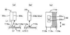
図6は、実装済基板110の表面に材質の異なる領域が存在する場合を示す図で、(a)(b)は側面図、(c)は(b)の平面図である。このように、互いに異なる材質で形成された領域113a、113bが隣接している場合には、図6(a)に示すように、照射部33aから受光部33bに向かう方向と領域113a、113bの境界線113cの延びる方向D2とが直交または交差するようにレーザー計測器33が配置されていると、材質が異なることによる影響を受けて、測定精度が低下する。そこで、この場合には、図6(b)、(c)に示すように、演算処理部41は、境界線113cの延びる方向D2と照射部33aから受光部33bに向かう方向とが平行になるように、レーザー計測器33の向きを変更する。言い換えると、境界線113cの延びる方向が入射経路L1と反射経路L2とを含む平面に平行となるようにしている。これによって、材質が異なることによる影響を受けないようにして、測定精度の低下を防ぐことができる。なお、図6では材質が異なる場合としているが、色が異なる場合も同様である。但し、光学認識用カメラ31により撮像して得られる画像としては、材質が異なる場合でも色が異なる場合でも、同様に2色(明暗)の領域として表れることとなる。この具体例では、方向D2が本発明の「第2方向」に相当している。
6A and 6B are diagrams showing a case where regions of different materials exist on the surface of the mounted
図7は、実装済基板110に背の高い部品120が実装されている場合を示す図で、(a)(b)は側面図、(c)は(b)の平面図である。このように背の高い部品120が実装されている場合には、図7(a)に示すように、照射部33aから受光部33bに向かう方向に部品120が存在して反射経路L2が部品120により遮断されると、測定不能となったり、部品120で反射される不要な乱反射光などにより測定精度が低下する。そこで、この場合には、図7(b)、(c)に示すように、レーザー計測器33の向きを変更して、入射経路L1および反射経路L2が部品120に遮られないようにする。これによって、背の高い部品120による影響を受けないようにして、測定精度の低下を防ぐことができる。
FIGS. 7A and 7B are diagrams showing a case where a
次に、上記のように構成された外観検査装置100の検査動作について、図8〜図10を参照しつつ説明する。図8は外観検査装置100の検査動作手順を示すフローチャートである。また、図9、図10は、図8のステップS12のレーザー測定準備処理サブルーチンを示すフローチャートである。
Next, the inspection operation of the
まず、ステップS1において、実装済基板110(被検査基板)が基板搬送コンベア10によって所定の検査位置まで搬送され、固定される。次に、ステップS2において、演算処理部41により、XYロボット20が駆動され、光学認識用カメラ31が実装済基板110上の所定のフィデューシャルマーク(基準マーク)位置の上方に移動される。そして、所定位置に形成された図略のフィデューシャルマークが光学認識用カメラ31によって撮像される。ステップS3では、フィデューシャルマーク(基準マーク)の撮像画像データが演算処理部41により画像認識されることによって、実装済基板110の位置補正が行われる。これにより、外観検査装置100の位置座標と実装済基板110(基板CADデータ)上の位置とが対応付けられ、検査処理を行う準備が完了する。以下、ステップS4〜ステップS9において、光学認識用カメラ31による実装済基板110の撮像画像を用いた実装状態の検査処理が行われる。
First, in step S1, the mounted substrate 110 (substrate to be inspected) is transported to a predetermined inspection position by the
ステップS4では、演算処理部41によって、光学認識用カメラ31による撮像が行われていない領域(未撮像領域)が実装済基板110上に存在するか否かが判断される。すなわち、光学認識用カメラ31の撮像範囲(視野)は一定範囲に限られているので、実装済基板110の撮像は所定領域毎に分割して複数回に分けて行われる。そこで、ステップS4で未撮像領域が存在するか否かが判断され、未撮像領域が存在する場合には(ステップS4でYES)、ステップS5に進む。一方、実装済基板110上の全領域が撮像されて未撮像領域が存在しない場合には(ステップS4でNO)、ステップS10に移行する。
In step S <b> 4, the
未撮像領域が存在する場合には、ステップS5において、演算処理部41により、記憶部42に格納された基板CADデータに基づいてXYロボット20が駆動され、光学認識用カメラ31が次の撮像領域を撮像するための所定の画像検査位置に移動される。
If there is an unimaged area, in step S5, the
そして、ステップS6において、光学認識用カメラ31によって実装済基板110上の所定領域(検査領域)が撮像される。撮像画像は画像処理部45によって認識(画像認識)するのに適した画像データとなるように処理され、演算処理部41に出力される。
In step S <b> 6, a predetermined area (inspection area) on the mounted
次に、ステップS7において、演算処理部41が画像データの画像認識を行うことによって、撮像画像データ(撮像領域)内に写った部品120や半田接合部などの検査対象となる部位(検査部位)が認識される。そして、検査部位毎に、記憶部42に格納された基板CADデータに基づいて、部品120の実装位置ずれ(実装位置の設計位置からの位置ずれ)や向き、および端子部121の曲がりや立ち上がりの有無などが検出される。また、半田接合部の位置や形状が検出される。画像認識が完了すると、撮像画像データは記憶部42に格納される。
Next, in step S7, when the
そして、ステップS8において、撮像領域内の検査部位について、検出された部品120の位置ずれおよび向きや、半田接合部の位置および形状などに基づいて、検査判定(良否の判定)が行われる。半田接合部については、画像認識によって、未半田や半田位置ずれ、リード浮きなどの不良状態か否かが判別される。一方、実装済基板110に対して略垂直上方(+Z方向)から撮像した撮像画像データから判別することが困難な検査部位(半田接合部)については、良品と判定されて、後述するステップS10以降のレーザー測定の対象となる。したがって、この画像検査判定によって、検査部位の良否についての1次判定が行われるとともに、良品と判定された部品120の位置情報(位置、向きおよび位置ずれ量など)および半田接合部の位置情報などが、後続するレーザー測定のために画像処理結果として生成される。
In step S8, inspection determination (determination of pass / fail) is performed on the inspection site in the imaging region based on the detected positional deviation and orientation of the
その後、ステップS9において、演算処理部41により、撮像領域(撮像画像データ)内の検査部位について、未検査部位が存在するか否かが判定される。撮像領域(撮像画像データ)内に検査が終了していない検査部位が残っている場合には(ステップS9でYES)、ステップS7に戻り、その検査部位について画像認識および検査判定が行われる。一方、撮像領域(撮像画像データ)内の全ての検査部位について検査が終了して未検査部位が存在しない場合には(ステップS9でNO)、ステップS4に移行して、再び未撮像領域が存在するか否かが判定される。このようにステップS4〜ステップS9までが繰り返されることによって、実装済基板110上の撮像領域毎に撮像が行われ、撮像領域内の検査部位毎に撮像画像データに基づく検査が行われる。この結果、ステップS4で未撮像領域なしと判定された場合(ステップS10に進む場合)には、実装済基板110の全体において、レーザー測定の対象となる部品120およびその部品120の半田接合部の位置情報が画像処理結果(ステップS8参照)として特定される。以降のステップS10〜S15において、画像検査により良品と判定された各検査部位に対して、レーザー測定が行われる。
Thereafter, in step S9, the
そこで、ステップS10では、演算処理部41によって、レーザー測定対象の部品120(半田接合部)が存在するか否かが判定される。レーザー測定対象の部品120(半田接合部)が存在する場合には、ステップS11に進む。
Therefore, in step S10, the
ステップS11では、レーザー測定対象の部品120の内から1つの部品120に着目して、レーザー測定が行われていない検査部位(未レーザー測定部位)が存在するか否かが判定される。すなわち、図1に示すように、部品120に端子部121が複数存在する場合には、それぞれの端子部121の半田接合部(検査部位)に対してレーザー測定が行われる。未レーザー測定部位が存在する場合には、ステップS12に進み、レーザー測定部位(未レーザー測定部位)の内からさらに1つのレーザー測定部位に着目して、そのレーザー測定部位におけるレーザー測定準備処理が行われる。ここで、図9、図10を参照して、レーザー測定準備処理のサブルーチンについて説明する。
In step S11, it is determined whether or not there is an inspection site (unlased measurement site) where laser measurement is not performed by paying attention to one
まず、ステップS21において、演算処理部41により、レーザー測定部位の位置情報が抽出される。具体的には、着目している検査部位(レーザー測定部位)についての画像検査判定(ステップS8参照)によって生成された画像処理結果の情報と、図略のエンコーダから取得したモータ位置情報(光学認識用カメラ31の位置情報)と、着目しているレーザー測定部位(検査部位)を撮像した撮像画像データとに基づいて、レーザー測定を行うための正確な位置情報が算出される。
First, in step S21, the position information of the laser measurement site is extracted by the
次に、ステップS22において、演算処理部41により、着目しているレーザー測定部位(検査部位)について、図5を参照して説明したような段差が存在するか否かが判断される。この判断は、記憶部42に格納されている上記撮像画像データおよび上記基板CADデータに基づき行われる。そして、段差があれば(ステップS22でYES)、ステップS27に移行する一方、段差が存在しなければ(ステップS22でNO)、ステップS23において、測定部位の近傍に障害物、すなわち入射経路L1または反射経路L2を遮るような他の部品120が存在するか否かが判断される。この判断は、記憶部42に格納されている上記撮像画像データ、上記基板CADデータ、上記部品外観データベースなどに基づき行われる。そして、障害物があれば(ステップS23でYES)、ステップS27に移行する。
Next, in step S <b> 22, the
一方、障害物がなければ(ステップS23でNO)、ステップS24において、当該レーザー測定部位の画像処理データが記憶部42から取得され、その視野(撮像領域)内が均一であるか否かが判断される。つまり、図6を参照して説明したような、色や材質が異なり境界線が明確な領域が存在すれば、均一でないと判断され、色や材質が変化しないか、または徐々に変化して境界線が不明確な領域であれば、均一であると判断される。そして、視野内が均一と判断されると(ステップS25でYES)、このサブルーチンを終了する。
On the other hand, if there is no obstacle (NO in step S23), in step S24, image processing data of the laser measurement site is acquired from the
一方、視野内が均一でないと判断されると(ステップS25でNO)、ステップS26において、視野内の明暗(光の強度値の差異)の変化が認識される。つまり、図6を参照して説明したような、色や材質が異なる領域の境界線が検出される。続いて、ステップS27において、レーザー計測器33の方向が取得される。つまり、回転用モータ331の図略のエンコーダから取得したモータ位置情報に基づいて、現在のレーザー計測器33の向きが取得される。
On the other hand, if it is determined that the field of view is not uniform (NO in step S25), a change in brightness (difference in light intensity value) in the field of view is recognized in step S26. That is, the boundary line of a region having a different color or material as described with reference to FIG. 6 is detected. Subsequently, in step S27, the direction of the
次いで、ステップS28において、レーザー計測器33を回転させることで、段差、障害物、色や材質による影響を回避できるか否かが判断される。例えば図5〜図7を参照して説明した例では、回避できると判断される。一方、例えばレーザー測定部位の近傍に、縦方向および横方向(図1におけるX方向およびY方向)の両方向の段差や境界線が存在する場合には、回避できないと判断される。そして、ステップS28において回避できないと判断されると(ステップS28でNO)、報知ユニット50の表示パネルや警告ブザーなどによりユーザに警告して(ステップS29)、このサブルーチンを終了する一方、回避できると判断されると(ステップS28でYES)、図5〜図7を参照して説明したようにレーザー計測器33を回転させて(ステップS30)、このサブルーチンを終了する。図9、図10のレーザー測定準備処理サブルーチンが終了すると、図8のステップS13に移行する。
Next, in step S28, it is determined whether or not the
ステップS13では、演算処理部41によってXYロボット20が駆動され、レーザー計測器33がレーザー測定を行うためのレーザー測定部位に移動される。ここで、図10のステップS30においてレーザー計測器33を回転したときは、上記したように照射部33aの位置が変化しているので、その変化を加味して、XYロボット20の駆動が制御される。
In step S13, the
次に、ステップS14において、レーザー計測器33により、着目しているレーザー測定部位の測定が行われる。すなわち、着目しているレーザー測定部位、例えば半田接合部において、複数の測定対象物についてレーザー測定が実行される。これによって、半田接合部の最大高さが取得されるとともに、各測定対象物の高さ情報(外形形状)に基づいて、半田接合部の半田容積が推定される。
Next, in step S <b> 14, the
ステップS14でレーザー測定が終了すると、ステップS15において、演算処理部41によって測定値に基づく判定処理が行われる。すなわち、着目しているレーザー測定部位(例えば半田接合部)について、最大高さや推定された半田容積に基づいて、良否が判定される。これにより、撮像画像データに基づく検査判定(ステップS8参照)で良品と判定された半田接合部について、レーザー測定によって、さらに詳細に判定することが可能となる。
When the laser measurement is completed in step S14, a determination process based on the measurement value is performed by the
ステップS15に続いてステップS11に戻り、着目している部品120について、未レーザー測定部位が存在するか否かが判定される。これにより、例えば部品120においてレーザー測定が行われていない他の半田接合部が存在する場合には、次に、その半田接合部に着目して、ステップS12〜S15の処理が行われる。一方、着目している部品120について、未レーザー測定部位が存在しない場合には、ステップS10に戻る。
Following step S15, the process returns to step S11, and it is determined whether or not there is a non-laser measurement site for the
そして、ステップS10において、演算処理部41によって、他にレーザー測定対象の部品120(例えば半田接合部を有する部品)が存在するか否かが判定される。レーザー測定対象の部品120が存在する場合には、ステップS11に進む。このようにして全てのレーザー測定対象の部品120について、レーザー測定部位毎にそれぞれレーザー測定準備処理サブルーチンが実行されるとともに、レーザー測定が行われる。一方、全てのレーザー測定対象の部品120について、レーザー測定が終了すると、ステップS10でレーザー測定対象の部品なしと判断されて、外観検査装置100による実装済基板110の検査動作が終了する。そして、検査が終了した実装済基板110は、基板搬送コンベア10によって搬出され、次の実装済基板110(被検査基板)が搬入される。このようにして、外観検査装置100による実装済基板110の検査動作が行われる。
In step S10, the
以上のように、本実施形態では、モータ331によりレーザー計測器33を回転することによって、レーザー計測器33の向きを変更可能に構成している。そして、光学認識用カメラ31により実装済基板110を撮像した画像、基板CADデータ、部品形状データベースなどに基づき、段差などがあるか否かを判定し、その判定結果に応じて、レーザー計測器33の向きを制御している。すなわち、段差112があると判定したときは、段差112の延びる方向D1が入射経路L1と反射経路L2とを含む平面に平行となるように、レーザー計測器33の向きを制御している。また、入射経路L1または反射経路L2が部品120により遮られると判定したときは、遮られないようにレーザー計測器33の向きを制御している。また、色や材質の異なる領域113a、113bがあると判定したときは、その境界線113cの延びる方向D2が入射経路L1と反射経路L2とを含む平面に平行となるように、レーザー計測器33の向きを制御している。これによって、1つのレーザー計測器33、つまり最小個数の照射部および受光部のみで、段差などによる影響を受けることなく、レーザー光による測定を精度良く行うことが可能になっている。
As described above, in this embodiment, the
また、本実施形態によれば、照射部33aと受光部33bとの略中央に回転軸C1を設けているため、回転軸C1を中心とする最小回転半径は、回転軸C1から照射部33a(受光部33b)までの距離になっている。したがって、最小回転半径を小さくすることができ、レーザーユニット30bの小型化を図ることが可能になっている。
In addition, according to the present embodiment, since the rotation axis C1 is provided at the approximate center between the
なお、本発明は上記した実施形態に限定されるものではなく、その趣旨を逸脱しない限りにおいて上述したもの以外に種々の変更を行うことが可能である。例えば上記実施形態では、照射部33aと受光部33bとの略中央に回転軸C1を設けているが、本発明はこれに限られない。図11はレーザーユニットの変形形態を示す側断面図である。なお、図11では、上記実施形態と同一構成には同一符号を付している。図11のレーザーユニット301では、シャフト333の中心の回転軸C1と、照射部33aから照射されるレーザー光、つまり入射経路L1とが同心に設けられている。この形態によれば、レーザー計測器33を回転しても、照射部33aにより照射されるレーザー光の照射位置は変化しない。したがって、レーザー計測器33を回転したときに、XYロボット20により検査ユニット30を移動させて測定対象物111に対する位置決めを再度行う必要がない。
The present invention is not limited to the above-described embodiment, and various modifications other than those described above can be made without departing from the spirit of the present invention. For example, in the above embodiment, the rotation axis C1 is provided at the approximate center between the
また、上記実施形態では、受光部33bが測定対象物111からの反射光のうちの拡散反射成分を受光する拡散反射型のレーザー計測器33としているが、本発明はこれに限られない。図12は、レーザー計測器の変形形態を模式的に示す図である。図12のレーザー計測器302では、照射部303は、測定対象物111から実装済基板110の表面に対して垂直な方向に延びる回転軸C1に対して傾斜してレーザー光を測定対象物111に照射しており、受光部304は、回転軸C1に対して照射部303の反対側で正反射光を受光している。つまり、図12のレーザー計測器302は、入射経路L1と反射経路L2とが回転軸C1を中心として線対称の正反射型のレーザー計測器となっている。この形態でも、上記実施形態と同様の作用効果を得ることができる。
Moreover, in the said embodiment, although the light-receiving
また、上記実施形態では、照射部33aと受光部33bとをレーザー計測器33として一体的に設けているが、本発明はこれに限られない。例えば、照射部と受光部とを分離して設けておき、照射部を固定して受光部を移動させるような形態でもよい。あるいは、受光部を固定して、照射部を移動させるような形態でもよい。要は、入射経路L1と反射経路L2との測定対象物111から見た入受光関係を調整できる形態であればよい。
Moreover, in the said embodiment, although the
また、上記実施形態では、半導体レーザーなどのレーザー光を出射する発光素子を有する照射部33aを備えたレーザー計測器33を用いているが、これに限られず、例えばLEDなどの他の発光素子を有する照射部を備えた光計測器を用いてもよい。要は、発光素子から出射される光が測定対象物111で反射された反射光が受光部により好適に受光されて、測定対象物111の高さを測定できるものであればよい。
Moreover, in the said embodiment, although the
また、上記実施形態では、光学認識用カメラ31により撮像された画像および基板CADデータに基づき、実装済基板110に段差が含まれるか否かを判定しているが、本発明はこれに限られない。例えば、実際に段差が含まれる実装済基板110を光学認識用カメラ31により撮像した画像を記憶部42に格納しておき、演算処理部41は、光学認識用カメラ31により撮像した実装済基板110の画像と記憶部42に格納されている画像とを比較することで、実装済基板110に段差が含まれるか否かを判定するようにしてもよい。この形態によれば、記憶部42に格納されている、実際に段差が含まれる画像と比較しているので、被検査基板である実装済基板110に段差が含まれているか否かを容易に、かつ精度良く判定することができる。この形態では、段差が本発明の「特定の表面形状」に相当する。
Moreover, in the said embodiment, it is determined whether the mounted board |
また、上記実施形態では、部品120がプリント基板130に半田接合された実装済基板110を被検査基板としているが、本発明はこれに限られない。例えば、部品が半田接合される前の状態の基板を被検査基板として、部品の実装状態の検査を行う装置に適用してもよい。また、部品を実装する前の実装前基板、例えば印刷装置により半田の印刷処理が施された基板を被検査基板として、印刷状態の検査を行う装置に適用してもよい。
Moreover, in the said embodiment, although the mounted board |
また、上記実施形態では、光学認識用カメラ31の撮像方向が実装済基板110に対して略垂直となるように構成しているが、本発明はこれに限られず、光学認識用カメラが略垂直方向以外の斜め方向から被検査基板を撮像するようにしてもよい。
In the above embodiment, the imaging direction of the
また、上記実施形態では、光学認識用カメラ31により実装済基板110を撮像した画像と、部品外観データベースおよび基板CADデータなどの各種データとに基づいて、段差があるか否かなどを判定するようにしているが、本発明はこれに限られない。本発明では、少なくとも光学認識用カメラ31により実装済基板110を撮像した画像に基づいて段差などを判定するものであればよい。
In the above embodiment, whether or not there is a step is determined based on an image obtained by imaging the mounted
また、上記実施形態では、基板CADデータ、部品外観データベースなどの実装済基板110の段差、障害物、色や材質などの判定に用いる各種データを記憶部42に格納するように構成した例を示したが、本発明はこれに限られない。たとえば、上記各判定に用いる各種データを、外部入出力部44を介してネットワーク接続されたホストコンピュータなどに格納して、必要に応じて取得するように構成してもよい。
Moreover, in the said embodiment, the example comprised so that the various data used for determination, such as board | substrate CAD data and the level | step difference of the mounted board |
また、上記実施形態では、光学認識用カメラ31、照明部32およびレーザー計測器33などを備える検査ユニット30を、XYロボット20によってXY方向(水平方向)に移動させるように構成した例を示したが、本発明はこれに限られない。たとえば、検査ユニットをX方向にのみ移動可能に構成するとともに、Y方向に移動可能な基板テーブル上で実装済基板をY方向に移動させるように構成してもよい。また、検査ユニットを実装済基板上方の位置で固定的に設けるとともに、XY方向(水平方向)に移動可能な基板テーブル上で実装済基板をXY方向に移動させるように構成してもよい。
Moreover, in the said embodiment, the example which comprised so that the
31…光学認識用カメラ(撮像部)
33…レーザー計測器
33a…照射部
33b…受光部
41…演算処理部(制御部)
100…外観検査装置(検査装置)
110…実装済基板(被検査基板)
111…測定対象物
112…段差(表面形状、特定の表面形状)
113c…境界線
120…部品
D1…第1方向
D2…第2方向
L1…入射経路
L2…反射経路
31 ... Camera for optical recognition (imaging part)
33 ...
100 ... Appearance inspection device (inspection device)
110 ... Mounted board (board to be inspected)
111 ...
113c ...
Claims (8)
前記測定対象物に光を照射する照射部と、前記照射部から照射された前記光が前記測定対象物で反射された反射光を受光する受光部とを有するレーザー計測器と、
前記レーザー計測器を回転軸まわりに回転させることにより、前記照射部および前記受光部の少なくとも一方を回転方向に移動させて所定の位置で停止して位置決めすることによって、前記照射部から前記測定対象物に進む前記光の入射経路と、前記測定対象物から前記受光部に進む前記反射光の反射経路との前記測定対象物から見た入受光関係を設定する駆動部と、
前記測定対象物または前記測定対象物を含む周辺領域での前記被検査基板の表面の画像を撮像する撮像部と、
前記撮像部により撮像された画像に基づき前記駆動部を制御して前記入射経路と前記反射経路とのなす角を維持したまま前記入受光関係を調整する制御部と
を備え、
前記制御部は、前記実装済基板に実装される部品の外観に関する情報と、前記撮像部により撮像された画像とに基づき、前記入射経路と前記反射経路が前記部品と干渉しないように前記駆動部を制御して前記入受光関係を調整することを特徴とする検査装置。 The populated board part article is mounted to the substrate to be inspected, it said in an inspection apparatus for inspecting a measurement target in the inspection target substrate optically,
A laser measuring instrument having an irradiating unit for irradiating the measurement object with light, and a light receiving unit for receiving the reflected light reflected by the measuring object from the irradiating unit;
By rotating the laser measuring device around a rotation axis, the at least one of the irradiation unit and the light receiving unit is moved in the rotation direction, and stopped and positioned at a predetermined position, whereby the measurement object is moved from the irradiation unit. A drive unit that sets an incident / light-receiving relationship as viewed from the measurement object with respect to an incident path of the light traveling to the object and a reflection path of the reflected light traveling from the measurement object to the light receiving unit;
An imaging unit that captures an image of the surface of the substrate to be inspected in a peripheral region including the measurement object or the measurement object;
A control unit that controls the drive unit based on an image captured by the imaging unit and adjusts the incident / light-receiving relationship while maintaining an angle formed by the incident path and the reflection path ;
The controller is configured to prevent the incident path and the reflection path from interfering with the component based on information about the appearance of the component mounted on the mounted substrate and an image captured by the imaging unit. The inspection apparatus is characterized in that the light receiving / receiving relation is adjusted by controlling the input / output .
前記受光部は前記光の入射経路から離れた位置で前記反射光のうち拡散反射成分を受光し、
前記駆動部は前記光の入射経路と同心な軸を前記回転軸として前記照射部および前記受光部を一体的に回転移動させる請求項1に記載の検査装置。 The irradiation unit irradiates the measurement object with the light from a direction perpendicular to the surface of the substrate to be inspected,
The light receiving unit receives a diffuse reflection component of the reflected light at a position away from the light incident path;
The inspection apparatus according to claim 1, wherein the driving unit integrally rotates the irradiation unit and the light receiving unit about an axis that is concentric with the light incident path.
前記照射部は前記測定対象物から前記回転軸に対して傾斜して前記光を前記測定対象物に照射し、
前記受光部は前記回転軸に対して前記照射部の反対側で前記反射光を受光し、
前記駆動部は前記回転軸回りに前記照射部および前記受光部を一体的に回転移動させる請求項1に記載の検査装置。 The rotation axis is an axis extending in a direction perpendicular to the surface of the substrate to be inspected;
The irradiation unit irradiates the measurement object the light tilted with respect to the previous Kikai rotation axis from the object to be measured,
The light receiving unit receives the reflected light on the opposite side of the irradiation unit with respect to the rotation axis,
The inspection apparatus according to claim 1, wherein the driving unit integrally rotates the irradiation unit and the light receiving unit around the rotation axis.
前記制御部は、前記撮像部により撮像された前記画像と前記記憶部に記憶されている前記画像とを比較することで、前記撮像部により撮像された画像に前記特定の表面形状が含まれるか否かを判定し、前記特定の表面形状が含まれると判定すると、前記特定の表面形状に応じて前記駆動部を制御して前記入受光関係を調整する請求項4に記載の検査装置。 A storage unit for storing an image of a specific surface shape of the substrate to be inspected imaged by the imaging unit;
Whether the specific surface shape is included in the image captured by the imaging unit by comparing the image captured by the imaging unit with the image stored in the storage unit The inspection apparatus according to claim 4, wherein if it is determined whether or not the specific surface shape is included, the light receiving / receiving relationship is adjusted by controlling the driving unit according to the specific surface shape.
前記被検査基板上の測定対象物にレーザー計測器の照射部から光を照射するとともに、前記測定対象物で反射された反射光を前記レーザー計測器の受光部で受光して前記測定対象物を光学的に検査する第2工程とを備え、
前記第2工程は、前記実装済基板に実装される部品の外観に関する情報と前記第1工程により撮像された画像とに基づき、前記レーザー計測器を回転軸まわりに回転させることにより前記照射部および前記受光部の少なくとも一方を移動させて所定の位置で停止して位置決めすることによって、前記照射部から前記測定対象物に進む前記光の入射経路と、前記測定対象物から前記受光部に進む前記反射光の反射経路との前記測定対象物から見た入受光関係を前記入射経路と前記反射経路とのなす角を維持したまま、前記入射経路と前記反射経路とが前記部品と干渉しないように調整する工程を有することを特徴とする検査方法。 The populated board part article is mounted to the substrate to be inspected, a first step of taking an image of the surface of the inspected substrate in the peripheral region including the measurement target in the inspection target board or the object to be measured,
The measurement object on the substrate to be inspected is irradiated with light from the irradiation part of the laser measuring instrument, and the reflected light reflected by the measurement object is received by the light receiving part of the laser measuring instrument to A second step of optical inspection,
In the second step, the irradiation unit and the irradiation unit are rotated by rotating the laser measuring instrument around a rotation axis based on the information on the appearance of the component mounted on the mounted substrate and the image captured in the first step. By moving at least one of the light receiving units and stopping and positioning at a predetermined position, the light incident path that travels from the irradiation unit to the measurement object and the light that travels from the measurement object to the light receiving unit The incident / reception relationship of the reflected light and the reflected path as viewed from the object to be measured is maintained so that the incident path and the reflected path do not interfere with the component while maintaining the angle formed by the incident path and the reflected path. An inspection method comprising a step of adjusting.
Priority Applications (2)
| Application Number | Priority Date | Filing Date | Title |
|---|---|---|---|
| JP2010047969A JP5546292B2 (en) | 2010-03-04 | 2010-03-04 | Inspection apparatus and inspection method |
| CN 201110054011 CN102221345B (en) | 2010-03-04 | 2011-03-04 | Checking device and checking method |
Applications Claiming Priority (1)
| Application Number | Priority Date | Filing Date | Title |
|---|---|---|---|
| JP2010047969A JP5546292B2 (en) | 2010-03-04 | 2010-03-04 | Inspection apparatus and inspection method |
Publications (2)
| Publication Number | Publication Date |
|---|---|
| JP2011185608A JP2011185608A (en) | 2011-09-22 |
| JP5546292B2 true JP5546292B2 (en) | 2014-07-09 |
Family
ID=44777967
Family Applications (1)
| Application Number | Title | Priority Date | Filing Date |
|---|---|---|---|
| JP2010047969A Active JP5546292B2 (en) | 2010-03-04 | 2010-03-04 | Inspection apparatus and inspection method |
Country Status (2)
| Country | Link |
|---|---|
| JP (1) | JP5546292B2 (en) |
| CN (1) | CN102221345B (en) |
Families Citing this family (8)
| Publication number | Priority date | Publication date | Assignee | Title |
|---|---|---|---|---|
| CN103217435B (en) * | 2012-01-19 | 2017-02-15 | 昆山思拓机器有限公司 | Medical support detection device |
| TWI490077B (en) * | 2012-11-30 | 2015-07-01 | Ind Tech Res Inst | Calibration apparatus and a compensation controlling method for multi-axes machines using the same |
| KR101816616B1 (en) * | 2014-01-08 | 2018-01-09 | 야마하하쓰도키 가부시키가이샤 | Visual inspection device and visual inspection method |
| JP6447637B2 (en) * | 2015-06-25 | 2019-01-09 | Jfeスチール株式会社 | Surface defect detection apparatus, surface defect detection method, and steel material manufacturing method |
| WO2018012346A1 (en) * | 2016-07-15 | 2018-01-18 | 国立研究開発法人産業技術総合研究所 | Libs-type object sorting device |
| CN106254742B (en) * | 2016-08-31 | 2022-03-08 | 苏州朗坤自动化设备有限公司 | Double-camera image measuring mechanism |
| JP6462761B2 (en) * | 2017-04-26 | 2019-01-30 | Towa株式会社 | Product manufacturing apparatus and manufacturing method |
| JP6687656B2 (en) * | 2018-03-19 | 2020-04-28 | ファナック株式会社 | Inspection device and its inspection method |
Family Cites Families (8)
| Publication number | Priority date | Publication date | Assignee | Title |
|---|---|---|---|---|
| JPS6447939A (en) * | 1987-08-19 | 1989-02-22 | Mitsubishi Heavy Ind Ltd | Surface flaw inspecting device |
| JP2751435B2 (en) * | 1989-07-17 | 1998-05-18 | 松下電器産業株式会社 | Inspection method for soldering condition of electronic components |
| JP2973606B2 (en) * | 1991-07-12 | 1999-11-08 | 松下電器産業株式会社 | Appearance inspection device for soldering condition |
| JPH05142157A (en) * | 1991-11-22 | 1993-06-08 | Matsushita Electric Ind Co Ltd | Appearance inspecting device for soldered state |
| JP2531450B2 (en) * | 1993-09-13 | 1996-09-04 | 日本電気株式会社 | Laser displacement meter |
| JPH0814848A (en) * | 1994-07-01 | 1996-01-19 | Omron Corp | Inspection device and inspection method |
| TW200540939A (en) * | 2004-04-22 | 2005-12-16 | Olympus Corp | Defect inspection device and substrate manufacturing system using the same |
| CN101644657B (en) * | 2009-09-03 | 2011-03-23 | 浙江大学 | Rotation lighting method and device for big calibre precision optical component surface defect detection |
-
2010
- 2010-03-04 JP JP2010047969A patent/JP5546292B2/en active Active
-
2011
- 2011-03-04 CN CN 201110054011 patent/CN102221345B/en active Active
Also Published As
| Publication number | Publication date |
|---|---|
| JP2011185608A (en) | 2011-09-22 |
| CN102221345B (en) | 2013-10-30 |
| CN102221345A (en) | 2011-10-19 |
Similar Documents
| Publication | Publication Date | Title |
|---|---|---|
| JP5546292B2 (en) | Inspection apparatus and inspection method | |
| JP5421763B2 (en) | Inspection apparatus and inspection method | |
| JP3872007B2 (en) | Measuring device and inspection device | |
| KR101615946B1 (en) | Three-dimensional shape measuring apparatus | |
| KR100903882B1 (en) | Vision inpection system that equip laser displacement sensor and method thereof | |
| JP6330162B2 (en) | Bonding apparatus and method for detecting height of bonding object | |
| US11982522B2 (en) | Three-dimensional measuring device | |
| KR20130103060A (en) | Device and method for three-dimensional measurement | |
| KR20050043611A (en) | 3-dimensional measuring device | |
| JP5594923B2 (en) | Substrate surface height measuring method and apparatus | |
| KR101737954B1 (en) | Inspection apparatus and inspection method | |
| JP2009092485A (en) | Print solder inspection device | |
| JP2006292647A (en) | Apparatus for inspecting bonding wire | |
| JP4467599B2 (en) | Bonding equipment | |
| WO2022113369A1 (en) | Mounting-board inspection apparatus and inspection apparatus | |
| KR20200026245A (en) | Imaging Device, Bump Inspection Device and Imaging Method | |
| JP5954757B2 (en) | Appearance inspection device | |
| TWI585360B (en) | Optical system for inspection of semiconductor devices, methods of capturing images of a semiconductor substrate with the same, and calibrating a position of the same | |
| CN111199900A (en) | Apparatus and method for inspecting bonded semiconductor chips | |
| JP4189111B2 (en) | Surface mount component mounting machine and electronic component detection method in surface mount component mounter | |
| JP2002267415A (en) | Semiconductor measuring instrument | |
| JPH11230718A (en) | Ball height measuring method of ball grid array | |
| WO2022091927A1 (en) | Position displacement detection method, position displacement detection device, positioning device, and inspection device | |
| KR20080018343A (en) | 4 direction surface mount technology lead inspector | |
| JP2001124523A (en) | Bump-top detecting method and method and apparatus for measuring bump height using the same |
Legal Events
| Date | Code | Title | Description |
|---|---|---|---|
| A621 | Written request for application examination |
Free format text: JAPANESE INTERMEDIATE CODE: A621 Effective date: 20120903 |
|
| A977 | Report on retrieval |
Free format text: JAPANESE INTERMEDIATE CODE: A971007 Effective date: 20130717 |
|
| A131 | Notification of reasons for refusal |
Free format text: JAPANESE INTERMEDIATE CODE: A131 Effective date: 20130723 |
|
| A521 | Request for written amendment filed |
Free format text: JAPANESE INTERMEDIATE CODE: A523 Effective date: 20130919 |
|
| A02 | Decision of refusal |
Free format text: JAPANESE INTERMEDIATE CODE: A02 Effective date: 20131105 |
|
| A521 | Request for written amendment filed |
Free format text: JAPANESE INTERMEDIATE CODE: A523 Effective date: 20140204 |
|
| A911 | Transfer to examiner for re-examination before appeal (zenchi) |
Free format text: JAPANESE INTERMEDIATE CODE: A911 Effective date: 20140212 |
|
| TRDD | Decision of grant or rejection written | ||
| A01 | Written decision to grant a patent or to grant a registration (utility model) |
Free format text: JAPANESE INTERMEDIATE CODE: A01 Effective date: 20140507 |
|
| A61 | First payment of annual fees (during grant procedure) |
Free format text: JAPANESE INTERMEDIATE CODE: A61 Effective date: 20140513 |
|
| R150 | Certificate of patent or registration of utility model |
Ref document number: 5546292 Country of ref document: JP Free format text: JAPANESE INTERMEDIATE CODE: R150 |
|
| R250 | Receipt of annual fees |
Free format text: JAPANESE INTERMEDIATE CODE: R250 |
|
| R250 | Receipt of annual fees |
Free format text: JAPANESE INTERMEDIATE CODE: R250 |
|
| R250 | Receipt of annual fees |
Free format text: JAPANESE INTERMEDIATE CODE: R250 |
|
| R250 | Receipt of annual fees |
Free format text: JAPANESE INTERMEDIATE CODE: R250 |
|
| R250 | Receipt of annual fees |
Free format text: JAPANESE INTERMEDIATE CODE: R250 |
|
| R250 | Receipt of annual fees |
Free format text: JAPANESE INTERMEDIATE CODE: R250 |
|
| R250 | Receipt of annual fees |
Free format text: JAPANESE INTERMEDIATE CODE: R250 |