JP5545016B2 - Imaging device - Google Patents
Imaging device Download PDFInfo
- Publication number
- JP5545016B2 JP5545016B2 JP2010109984A JP2010109984A JP5545016B2 JP 5545016 B2 JP5545016 B2 JP 5545016B2 JP 2010109984 A JP2010109984 A JP 2010109984A JP 2010109984 A JP2010109984 A JP 2010109984A JP 5545016 B2 JP5545016 B2 JP 5545016B2
- Authority
- JP
- Japan
- Prior art keywords
- color
- monochrome
- image data
- light
- image sensor
- Prior art date
- Legal status (The legal status is an assumption and is not a legal conclusion. Google has not performed a legal analysis and makes no representation as to the accuracy of the status listed.)
- Expired - Fee Related
Links
Images


Classifications
-
- H—ELECTRICITY
- H04—ELECTRIC COMMUNICATION TECHNIQUE
- H04N—PICTORIAL COMMUNICATION, e.g. TELEVISION
- H04N5/00—Details of television systems
- H04N5/30—Transforming light or analogous information into electric information
- H04N5/33—Transforming infrared radiation
-
- H—ELECTRICITY
- H04—ELECTRIC COMMUNICATION TECHNIQUE
- H04N—PICTORIAL COMMUNICATION, e.g. TELEVISION
- H04N23/00—Cameras or camera modules comprising electronic image sensors; Control thereof
-
- H—ELECTRICITY
- H04—ELECTRIC COMMUNICATION TECHNIQUE
- H04N—PICTORIAL COMMUNICATION, e.g. TELEVISION
- H04N23/00—Cameras or camera modules comprising electronic image sensors; Control thereof
- H04N23/10—Cameras or camera modules comprising electronic image sensors; Control thereof for generating image signals from different wavelengths
- H04N23/12—Cameras or camera modules comprising electronic image sensors; Control thereof for generating image signals from different wavelengths with one sensor only
-
- H—ELECTRICITY
- H04—ELECTRIC COMMUNICATION TECHNIQUE
- H04N—PICTORIAL COMMUNICATION, e.g. TELEVISION
- H04N23/00—Cameras or camera modules comprising electronic image sensors; Control thereof
- H04N23/45—Cameras or camera modules comprising electronic image sensors; Control thereof for generating image signals from two or more image sensors being of different type or operating in different modes, e.g. with a CMOS sensor for moving images in combination with a charge-coupled device [CCD] for still images
-
- H—ELECTRICITY
- H04—ELECTRIC COMMUNICATION TECHNIQUE
- H04N—PICTORIAL COMMUNICATION, e.g. TELEVISION
- H04N23/00—Cameras or camera modules comprising electronic image sensors; Control thereof
- H04N23/80—Camera processing pipelines; Components thereof
- H04N23/84—Camera processing pipelines; Components thereof for processing colour signals
-
- H—ELECTRICITY
- H04—ELECTRIC COMMUNICATION TECHNIQUE
- H04N—PICTORIAL COMMUNICATION, e.g. TELEVISION
- H04N7/00—Television systems
- H04N7/18—Closed-circuit television [CCTV] systems, i.e. systems in which the video signal is not broadcast
Landscapes
- Engineering & Computer Science (AREA)
- Multimedia (AREA)
- Signal Processing (AREA)
- Human Computer Interaction (AREA)
- Color Television Image Signal Generators (AREA)
- Studio Devices (AREA)
- Exposure Control For Cameras (AREA)
- Cameras In General (AREA)
Description
本発明は、撮像装置に関する。 The present invention relates to an imaging apparatus.
屋外などを撮影する広域監視カメラでは、以下の3点が主に要求される。第一の要求は、霧や霞などで見えにくい撮影条件であっても注目する被写体を鮮明に撮像できることである。第二の要求は、照度の低い暗い環境でも被写体を撮像できることである。第三の要求は、服の色等の色情報による識別が重視される場合も多いため、カラー画像が得られることである。 The following three points are mainly required for a wide-area surveillance camera for photographing outdoors and the like. The first requirement is that a subject to be noticed can be clearly imaged even under shooting conditions that are difficult to see due to fog or haze. The second requirement is that the subject can be imaged even in a dark environment with low illuminance. The third requirement is that color images can be obtained because identification by color information such as clothes color is often emphasized.
従来の単板カラー撮像素子を用いたカメラを使用した場合の上述した3つの要求の具備又は不具備について説明する。 A description will be given of whether the above three requirements are satisfied or not when a conventional camera using a single-plate color image sensor is used.
まず、第一の要求について説明する。被写体を鮮明に撮像するには、被写体で反射した光がカメラの撮像素子まで減衰せずに到達することが重要である。被写体で反射した光がカメラまで届くまでの空間には、空気(N2分子等)、霧などの水分、スモッグや砂などの浮遊粒子などが存在する。そして、これらの物体が光を散乱させることで鮮明な撮影を阻害する。 First, the first request will be described. In order to capture a clear image of the subject, it is important that the light reflected by the subject reaches the image sensor of the camera without being attenuated. In the space until the light reflected from the subject reaches the camera, there are air (such as N 2 molecules), moisture such as mist, suspended particles such as smog and sand. And these objects scatter light and inhibit clear photographing.
直径0.37nmの空気分子や一部のスモッグのように浮遊粒子が小さい場合に成り立つRayleighの散乱式によれば、散乱強度は光線波長の−4乗に比例する。また、直径が1000nm〜50μm程度といわれる霧などの粒子径の場合には、Mieの散乱式が適用され、散乱強度は光線波長の−2乗程度に比例する。波長400nm〜700nmの可視光では、特に青や緑の波長が散乱されやすく、青や緑の波長がカメラに到達しない。そのため、可視光を受光するカメラでは、得られる画像は眼で見た状態に近く遠方は霞み見通しが利かなくなる。 According to Rayleigh's scattering equation, which is established when airborne particles with a diameter of 0.37 nm and some smog are small, the scattering intensity is proportional to the −4th power of the light wavelength. Further, in the case of a particle diameter such as fog having a diameter of about 1000 nm to 50 μm, the Mie scattering formula is applied, and the scattering intensity is proportional to the −2 power of the light wavelength. In visible light having a wavelength of 400 nm to 700 nm, particularly blue and green wavelengths are easily scattered, and blue and green wavelengths do not reach the camera. For this reason, in a camera that receives visible light, the obtained image is close to the state seen with the eyes, and the distant view cannot be seen in the distance.
次に、第二の要求について説明する。単板カラー撮像素子は、受光素子の前に赤・緑・青の色フィルタを設置しているため、赤・緑・青の各色の受光素子がいずれも、モノクロ撮像素子と比べて感度が低くなる。照度の低い暗い環境での撮像における感度不足を補うため、撮像素子の前に設置してあるIRカットフィルタを一時的に退避し、かつ赤外光で被写体を照明する方法(例えばナイトモード撮影)もある。しかし、赤外線撮影では、カラー撮影できないことに加え、受光素子の前の赤・緑・青の色フィルタを通過することから大幅な感度向上が難しい。 Next, the second request will be described. The single-chip color image sensor has a red, green, and blue color filter installed in front of the light-receiving element, so the red, green, and blue light-receiving elements are all less sensitive than the monochrome image sensor. Become. A method of temporarily retracting the IR cut filter installed in front of the image sensor and illuminating the subject with infrared light (for example, night mode photography) to compensate for the lack of sensitivity in imaging in a dark environment with low illuminance There is also. However, in infrared imaging, in addition to being unable to perform color imaging, it is difficult to significantly improve sensitivity because it passes through red, green, and blue color filters in front of the light receiving element.
これに対して、単板モノクロ撮像素子は、単板カラー撮像素子と比較して、高感度でかつ空間解像度の高い撮影が可能という利点がある。しかしながら、モノクロ撮像素子は、当然ながら色情報を取得することが不可能であるため、上述した第三の要求を満たすことができない。 On the other hand, the single-plate monochrome image pickup device has an advantage of being capable of photographing with high sensitivity and high spatial resolution as compared with the single plate color image pickup device. However, since the monochrome imaging element cannot naturally acquire color information, it cannot satisfy the third requirement described above.
特許文献1では、モノクロ撮像素子とカラー撮像素子をそれぞれ有し、更に入射した光を分岐させ分岐した光をそれぞれモノクロ撮像素子とカラー撮像素子に照射する光学部材が配置された撮像装置が開示されている。しかし、特許文献1の光学部材は、入射光を反射光と透過光に分岐するハーフミラーであり、反射光と透過光の波長成分はいずれも同じである。そのため、モノクロ撮像素子とカラー撮像素子には、同じ波長成分の光が入射する。そのため、モノクロ撮像素子も可視光領域の波長成分も受光していたため、輝度情報を抽出する際に可視光を含有する画像データを使用することになる。従って、上述した第一の要求を満たさず、被写体を鮮明に撮像できないという問題があった。
そこで、本発明は、上記問題に鑑みてなされたものであり、本発明の目的とするところは、霞などで見えにくい撮影条件や、照度の低い暗い環境でも被写体を撮像可能で、カラー画像を得ることが可能な、新規かつ改良された撮像装置を提供することにある。 Therefore, the present invention has been made in view of the above problems, and an object of the present invention is to capture a subject under a shooting condition that is difficult to see with a moth or the like, or in a dark environment with low illuminance, and a color image. It is an object of the present invention to provide a new and improved imaging device that can be obtained.
上記課題を解決するために、本発明のある観点によれば、被写体から入射した光を可視光領域の波長成分のみからなる第一の光と、第一の光を含まず可視光領域以外の波長成分のみからなる第二の光に分光する光学部材と、光学部材から照射された第一の光を受光するカラー撮像素子と、光学部材から照射された第二の光を受光するモノクロ撮像素子とを備える撮像装置が提供される。 In order to solve the above-described problem, according to one aspect of the present invention, the light incident from the subject includes the first light composed only of the wavelength component of the visible light region and the light other than the visible light region that does not include the first light. An optical member that splits into second light consisting only of a wavelength component, a color image sensor that receives the first light emitted from the optical member, and a monochrome image sensor that receives the second light emitted from the optical member An imaging device is provided.
上記光学部材は、第一の光を反射し第二の光を透過する分光ミラーであるとよい。 The optical member may be a spectroscopic mirror that reflects the first light and transmits the second light.
上記カラー撮像素子とモノクロ撮像素子の光学サイズが同等である場合、カラー撮像素子の画素数をCn、モノクロ撮像素子の画素数をMnとすると、Mn≧Cnであるとよい。 In the case where the optical sizes of the color imaging device and the monochrome imaging device are equal, it is preferable that Mn ≧ Cn, where Cn is the number of pixels of the color imaging device and Mn is the number of pixels of the monochrome imaging device.
上記カラー撮像素子からカラー画像データを取得し、モノクロ画像素子からモノクロ画像データを取得する画像取得部と、カラー画像データから色情報を抽出する色情報抽出部と、モノクロ画像データから輝度情報を抽出する輝度情報抽出部と、抽出された色情報と輝度情報とを合成し合成画像データを生成する合成部とを備えてもよい。 An image acquisition unit that acquires color image data from the color image sensor and acquires monochrome image data from the monochrome image element, a color information extraction unit that extracts color information from the color image data, and luminance information from the monochrome image data A luminance information extracting unit that combines the extracted color information and luminance information to generate combined image data.
上記カラー撮像素子とモノクロ撮像素子は、カラー画像データの被写体像とモノクロ画像データの被写体像とが一致するように位置決めされてもよい。 The color imaging device and the monochrome imaging device may be positioned so that the subject image of the color image data and the subject image of the monochrome image data match.
以上説明したように本発明によれば、霞などで見えにくい撮影条件や、照度の低い暗い環境でも被写体を撮像可能で、カラー画像を得ることができる。 As described above, according to the present invention, it is possible to capture a subject even in shooting conditions that are difficult to see with a eyelid or in a dark environment with low illuminance, and a color image can be obtained.
以下に添付図面を参照しながら、本発明の好適な実施の形態について詳細に説明する。なお、本明細書及び図面において、実質的に同一の機能構成を有する構成要素については、同一の符号を付することにより重複説明を省略する。 Exemplary embodiments of the present invention will be described below in detail with reference to the accompanying drawings. In addition, in this specification and drawing, about the component which has the substantially same function structure, duplication description is abbreviate | omitted by attaching | subjecting the same code | symbol.
なお、説明は以下の順序で行うものとする。
1.一実施形態の構成及び動作
2.変更例
The description will be made in the following order.
1. 1. Configuration and operation of one embodiment Example of change
<1.一実施形態の構成及び動作> <1. Configuration and Operation of One Embodiment>
[撮像装置100]
まず、本発明の一実施形態に係る撮像装置100について説明する。撮像装置100は、画像処理装置102が信号処理回路として内蔵されている。
[Imaging device 100]
First, the
図1は、本実施形態に係る撮像装置100を示すブロック図である。撮像装置100は、例えば光学系101と画像処理装置102からなる。光学系101は、図1に示すようにカラー画像データとモノクロ画像データを別々に画像処理装置102に送る。
FIG. 1 is a block diagram illustrating an
図2は、本実施形態に係る光学系101を示す説明図である。図2は、各光学部品の概略的な外観と光路を示している。
FIG. 2 is an explanatory diagram showing the
光学系101は、前玉レンズ151と、分光ミラー152と、レンズ群153と、カラー撮像素子154と、レンズ群155と、モノクロ撮像素子156などからなる。光学系101は、分光ミラー152が、可視光領域の波長成分のみからなる第一の光と、第一の光を含まず可視光領域以外の波長成分のみからなる第二の光に分光する。そして、カラー撮像素子154が、光学部材から照射された第一の光を受光し、モノクロ撮像素子156が、光学部材から照射された第二の光を受光する。
The
前玉レンズ151は、被写体で反射した光を受けて、被写体からの光を透過屈折させ、光を分光ミラー152に照射する。
The
分光ミラー152は、表面にダイクロイック膜が蒸着されている。そして、分光ミラー152は、入射した光のうち可視光領域の波長成分である例えば675nm以下の可視光波長成分を反射し、入射した光のうち可視光領域以外の波長成分である例えば675nm以上の近赤外光線波長成分を透過させる。675nm以下の波長成分は、レンズ群153を透過してカラー撮像素子154に照射され結像し、675nm以上の波長成分は、レンズ群155を透過してモノクロ撮像素子156に照射され結像する。なお、分光ミラー152による波長成分の分光の境界値は、675nmに限定されず、他の値でもよい。
The
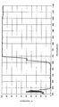
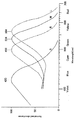
図5は、分光ミラー152で反射する光線の分光反射率を示すグラフである。図5に示すように、分光ミラー152によって、主に波長675nm以下の光がカラー撮像素子154に導かれる。人の眼の分光感度は、図7のように示されるといわれるため、カラー撮像素子154に導かれる光線の波長は、概ね可視光領域であるといえる。図7は、人間の錐体細胞(S,M,L)と桿体細胞(R)が含む視物質の吸収スペクトルを示すグラフである。
FIG. 5 is a graph showing the spectral reflectance of the light beam reflected by the
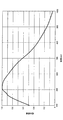
図6は、分光ミラー152を透過する光線の分光透過率を示すグラフである。図6に示すように、分光ミラー152によって、主に波長675nm以上の光がモノクロ撮像素子156に導かれる。図7を参照すると、モノクロ撮像素子156に導かれる光線の波長は、概ね可視光領域以外の領域であるといえる。
FIG. 6 is a graph showing the spectral transmittance of the light beam that passes through the
なお、撮影レンズを含む他の光学部品は、波長400nm〜1100nmにおいて十分な透過率を有しており、カラー撮像素子154やモノクロ撮像素子156に到達する光を遮断することはない。
Note that other optical components including the photographing lens have sufficient transmittance at wavelengths of 400 nm to 1100 nm, and do not block light reaching the
カラー撮像素子154及びモノクロ撮像素子156としては、CCD固体撮像素子、MOS型固体撮像素子、CMOS型固体撮像素子等の各種の固体撮像素子を使用することができる。カラー撮像素子154は、受光素子の前に赤・緑・青の色フィルタが設置された撮像素子であり、赤成分・緑成分・青成分からなるカラー画像データを出力する。モノクロ撮像素子156は、受光素子の前に色フィルタが設置されない撮像素子であり、輝度情報からなるモノクロ画像データを出力する。
As the
図8は、カラー撮像素子154の分光感度特性を示すグラフである。図5で示した分光ミラー152で反射し、カラー撮像素子154に入射する波長675nm以下の波長領域と、図8で示したカラー撮像素子154が分光感度を有する領域が適合していることが分かる。従って、カラー撮像素子154は、無駄なく可視光をとらえることが可能となっている。
FIG. 8 is a graph showing the spectral sensitivity characteristics of the
図9は、モノクロ撮像素子156の分光感度特性を示すグラフである。図9に示すように、モノクロ撮像素子156は、可視光域に最大感度を示すものの、波長675nm〜1000nmの近赤外線領域においても、十分な感度を持っている。よって、モノクロ撮像素子156は、分光ミラー152を透過し、モノクロ撮像素子156に入射する可視光より波長の長い675nm以上の波長成分を受光することが可能である。
FIG. 9 is a graph showing the spectral sensitivity characteristics of the
カラー撮像素子154とモノクロ撮像素子156は、カラー画像データの被写体像とモノクロ画像データの被写体像とが一致するように位置決めされる。被写体像の一致のための位置決めは、機械的に行う方法と、画像合成時にソフトウエアを使用して行う方法と、双方を使用する方法がある。
The
カラー撮像素子154とモノクロ撮像素子156の光学サイズは、ほぼ同等であるとよい。この構成によれば、特に調整をしなくても、分光ミラー152で分岐された2つの光学系において、画角や焦点深度、並びに撮像領域をほぼ同等とすることができる利点を有する。
The optical sizes of the
カラー撮像素子154とモノクロ撮像素子156の光学サイズが同等である場合、カラー撮像素子154の画素数をCn、モノクロ撮像素子156の画素数をMnとしたとき、Mn≧Cnを満たすように構成する。この構成によれば、カラー撮像素子154の画素数Cnがモノクロ撮像素子156の画素数Mn以下であるため、カラー撮像素子154の各画素サイズがモノクロ撮像素子156の画素サイズに比べて大きくなる。その結果、カラー撮像素子154の感度を高くすることができ、画素数の多いカラー撮像素子と比較して感度を向上させることができる。一方、モノクロ撮像素子156の画素数Mnが多いので、モノクロ撮像素子156によって高い解像度が確保される。
When the optical sizes of the
[画像処理装置102の構成]
次に、図3を参照して、本発明の一実施形態に係る画像処理装置102の構成について説明する。図3は、本実施形態に係る画像処理装置102を示すブロック図である。
[Configuration of Image Processing Device 102]
Next, the configuration of the
画像処理装置102は、可視光領域の波長成分のみからなるカラー画像データから色情報を抽出し、可視光領域の波長成分を含まず可視光領域外の波長成分のみからなるモノクロ画像データから輝度情報を抽出して、色情報と輝度情報を合成し画像データを生成する。これによって、輝度情報を抽出する際に可視光を含有する画像データを使用しないため、被写体像が鮮明に表示される画像データを得られる。
The
画像処理装置102は、カラー画像データ取得部112と、モノクロ画像データ取得部114と、色情報抽出部122と、輝度情報抽出部124と、合成部130等からなる。
The
カラー画像データ取得部112は、画像取得部の一例であり、カラー撮像素子を使用して撮像された結果得られるカラー画像データを取得する。カラー撮像素子は、受光素子の前に赤・緑・青の色フィルタが設置された撮像素子であり、赤成分・緑成分・青成分からなるカラー画像データを出力する。
The color image
カラー撮像素子から取得するカラー画像データが、可視光領域の波長成分のみからなる場合、カラー画像データ取得部112は、そのまま可視光領域の波長成分のみからなるカラー画像データを色情報抽出部122に送る。または、カラー撮像素子から取得するカラー画像データが、可視光領域以外の赤外光成分等の波長成分を含む場合は、カラー画像データ取得部112は、可視光領域以外の波長成分を除去して、可視光領域の波長成分のみからなるカラー画像データを色情報抽出部122に送る。
When the color image data acquired from the color image sensor is composed of only the wavelength component in the visible light region, the color image
カラー画像データにおいて、赤外光成分等の波長成分が除去されることにより、人の知覚に合致した人の目に分かりやすいカラー画像が得られる。 By removing wavelength components such as infrared light components from the color image data, a color image that is easy to understand for the human eye that matches human perception can be obtained.
モノクロ画像データ取得部114は、画像取得部の一例であり、モノクロ撮像素子を使用して撮像された結果得られるモノクロ画像データを取得する。モノクロ撮像素子は、受光素子の前に色フィルタが設置されない撮像素子であり、輝度情報からなるモノクロ画像データを出力する。モノクロ撮像素子は、色フィルタが設置されていないためカラー撮像素子に比べて高感度であり、かつ空間解像度が高い撮像が可能となる。
The monochrome image
モノクロ撮像素子から取得するモノクロ画像データが、可視光領域以外の波長成分のみからなる場合、モノクロ画像データ取得部114は、そのまま可視光領域以外の波長成分のみからなるモノクロ画像データを輝度情報抽出部124に送る。または、モノクロ撮像素子から取得するモノクロ画像データが、可視光領域の波長成分を含む場合は、モノクロ画像データ取得部114は、可視光領域の波長成分を除去して、可視光領域以外の波長成分のみからなるモノクロ画像データを輝度情報抽出部124に送る。
When the monochrome image data acquired from the monochrome image sensor consists of only wavelength components outside the visible light region, the monochrome image
モノクロ画像データにおいて、可視光成分が除去されることにより、霧や霞などで見えにくい環境でも、被写体が鮮明なモノクロ画像が得られる。 By removing the visible light component from the monochrome image data, a monochrome image with a clear subject can be obtained even in an environment where it is difficult to see due to fog or haze.
上記カラー画像データは、所定値、例えば675nm以下の波長成分のみからなり、モノクロ画像データは、所定値、例えば675nm以上の波長成分のみからなるとよい。なお、所定値は上記例に限定されず、例えば上記カラー画像データは、400nm〜700nmの波長成分を含み、モノクロ画像データは、700nm〜1000nmの波長成分を含むようにしてもよい。また、上記カラー画像データは、短波長側半値波長が420nm〜460nmで長波長側半値波長が610nm〜650nmの波長成分を含み、モノクロ画像データは、短波長側半値波長が650nm〜750nmの波長成分を含むようにしてもよい。 The color image data may include only a predetermined value, for example, a wavelength component of 675 nm or less, and the monochrome image data may include only a predetermined value, for example, a wavelength component of 675 nm or more. The predetermined value is not limited to the above example. For example, the color image data may include a wavelength component of 400 nm to 700 nm, and the monochrome image data may include a wavelength component of 700 nm to 1000 nm. The color image data includes a wavelength component having a short wavelength half wavelength of 420 nm to 460 nm and a long wavelength half wavelength of 610 nm to 650 nm, and the monochrome image data includes a wavelength component having a short wavelength half wavelength of 650 nm to 750 nm. May be included.
色情報抽出部122は、カラー画像データ取得部112から受けた可視光領域の波長成分のみからなるカラー画像データを輝度情報Y1と、色差情報Cb,Crに分解し、色差情報Cb,Crを抽出する。色差情報Cb,Crは色情報の一例である。色情報抽出部122は、抽出した色差情報Cb,Crを合成部130に送る。輝度情報Y1は、合成部130における合成処理に使用されないため、合成部130に送らなくてもよい。
The color
RGB各8bitのカラー画像データを輝度情報Y1と、色差情報Cb,Crに分解するには、例えばRGB信号をYCbCr信号に変換する下記の数式1〜3を使用する。
In order to decompose RGB 8-bit color image data into luminance information Y1 and color difference information Cb, Cr, for example, the following
Y1= 0.257R+0.504G+0.098B+ 16 ……(数式1)
Cb=−0.148R−0.291G+0.439B+128 ……(数式2)
Cr= 0.439R−0.368G−0.071B+128 ……(数式3)
Y1 = 0.257R + 0.504G + 0.098B + 16 (Formula 1)
Cb = −0.148R−0.291G + 0.439B + 128 (Formula 2)
Cr = 0.439R−0.368G−0.071B + 128 (Formula 3)
輝度情報抽出部124は、モノクロ画像データ取得部114から受けた可視光領域以外の波長成分のみからなるモノクロ画像データを輝度情報Y2とする。そして、輝度情報抽出部124は、抽出した輝度情報Y2を合成部130に送る。
The luminance
合成部130は、色情報抽出部122から受けた色差情報Cb,Crと、輝度情報抽出部124から受けた輝度情報Y2を合成し、合成画像データを生成する。色差情報Cb,Crと輝度情報Y2を合成して、RGB各8bitのカラーの合成画像データを生成するには、例えばYCbCr信号をRGB信号に変換する下記の数式4〜6を使用する。
The synthesizing
R=1.164(Y2−16) −1.596(Cr−128) ……(数式4)
G=1.164(Y2−16)−0.391(Cb−128)−0.813(Cr−128) ……(数式5)
B=1.164(Y2−16)−2.018(Cb−128) ……(数式6)
R = 1.164 (Y2-16) -1.596 (Cr-128) (Formula 4)
G = 1.164 (Y2-16) -0.391 (Cb-128) -0.813 (Cr-128) (Formula 5)
B = 1.164 (Y2-16) -2.018 (Cb-128) (Formula 6)
[画像処理装置102の動作]
次に、図4を参照して、上述した本実施形態に係る画像処理装置102の合成処理について説明する。図4は、本実施形態に係る画像処理装置102の合成処理を示すフローチャートである。
[Operation of Image Processing Device 102]
Next, with reference to FIG. 4, the composition processing of the
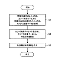
まず、画像処理装置102は、可視光領域の波長成分のみからなるカラー画像データと、可視光領域以外の波長成分のみからなるモノクロ画像データを取得する(ステップS1)。
First, the
次に、カラー画像データが輝度情報Y1、色差情報Cb,Crに分解され、カラー画像データから色差情報Cb,Crが抽出される。また、モノクロ画像データから輝度情報Y2が抽出される(ステップS2)。 Next, the color image data is decomposed into luminance information Y1 and color difference information Cb, Cr, and the color difference information Cb, Cr is extracted from the color image data. Also, luminance information Y2 is extracted from the monochrome image data (step S2).
その後、カラー画像データから抽出された色差情報Cb,Crと、モノクロ画像データから抽出された輝度情報Y2が合成されて合成画像データが生成される(ステップS3)。 Thereafter, the color difference information Cb, Cr extracted from the color image data and the luminance information Y2 extracted from the monochrome image data are combined to generate combined image data (step S3).
[本実施形態の効果]
本実施形態の撮像装置100は、例えば広域監視カメラに適用して最適な結果が得られる。本実施形態によれば、広域監視カメラにおける特に以下の三つの要求を満たすことが可能である。
[Effect of this embodiment]
The
第一の要求は、霧や霞などで見えにくい撮影条件であっても注目する被写体を鮮明に撮像できることである。第二の要求は、照度の低い暗い環境でも被写体を撮像できることである。第三の要求は、服の色等の色情報による識別が重視される場合も多いため、カラー画像が得られることである。 The first requirement is that a subject to be noticed can be clearly imaged even under shooting conditions that are difficult to see due to fog or haze. The second requirement is that the subject can be imaged even in a dark environment with low illuminance. The third requirement is that color images can be obtained because identification by color information such as clothes color is often emphasized.
まず、第一の要求について説明する。被写体を鮮明に撮像するには、被写体で反射した光が撮像素子まで減衰せずに到達することが重要である。本実施形態では、画像の解像度に支配的な輝度信号として、可視光より波長の長い675nm〜1000nmの近赤外光(NIR)を用いる。 First, the first request will be described. In order to capture a clear image of the subject, it is important that the light reflected by the subject reaches the image sensor without being attenuated. In the present embodiment, near-infrared light (NIR) of 675 nm to 1000 nm having a wavelength longer than that of visible light is used as a luminance signal dominant to the resolution of the image.
図10は、Rayleighの散乱式による散乱量と波長の関係を示すグラフである。Rayleighの散乱式は、下記の数式7で表される。Rayleighの散乱式によれば、d≦λ/πの場合、散乱強度は光線波長の−4乗に比例する。 FIG. 10 is a graph showing the relationship between the amount of scattering and the wavelength according to the Rayleigh scattering formula. Rayleigh's scattering formula is expressed by the following formula 7. According to Rayleigh's scattering formula, when d ≦ λ / π, the scattering intensity is proportional to the −4th power of the light wavelength.

Rayleighの散乱式によれば、近赤外光(NIR)は、400〜675nmの可視光より散乱量が小さい。そのため、空気中や、直径が光線波長のおおよそ1/3以下の浮遊粒子が漂う環境では、遠方や霞などで見えにくい撮影条件であっても、本実施形態の技術を適用することにより、通常のカメラよりも、注目する被写体を鮮明に撮像できる。 According to Rayleigh's scattering formula, near infrared light (NIR) has a smaller amount of scattering than visible light of 400 to 675 nm. Therefore, in the air or in an environment where floating particles with a diameter of approximately 1/3 or less of the wavelength of light are floating, even if the shooting conditions are difficult to see in the distance or the eyelid, the technique of the present embodiment is usually applied. This makes it possible to pick up the subject of interest more clearly than with the camera.
また、光線波長のおおよそ1/3以上の直径の浮遊粒子が漂う環境に適用できるMieの散乱式によれば、散乱量は波長の0〜−2乗に比例する。そのため、霧などの環境でも、近赤外光(NIR)は、可視光よりも散乱されにくい。よって、近赤外光(NIR)を利用する本実施形態では、通常のカメラよりも、霧などの環境でも被写体を鮮明に撮像できる。 In addition, according to Mie's scattering equation applicable to an environment where floating particles having a diameter of approximately 1/3 or more of the light wavelength drift, the amount of scattering is proportional to the 0th to -2nd power of the wavelength. Therefore, near-infrared light (NIR) is less likely to be scattered than visible light even in an environment such as fog. Therefore, in this embodiment using near-infrared light (NIR), a subject can be imaged more clearly in an environment such as fog than a normal camera.
次に、第二の要求について説明する。本実施形態によれば、照度の低い暗い環境でも被写体を撮像できる。本実施形態では、まず、通常のカラーカメラでは未使用の近赤外光(NIR)も利用し、かつ、夕暮れや人工照明はNIRを含むため、本実施形態は低照度時に有利である。加えて、本実施形態では、NIRを受光するために、カラー撮像素子154と比較して、より高感度でかつ空間解像度の高い撮影が可能なモノクロ撮像素子156を使用しているため、本実施形態は低照度時に有利である。
Next, the second request will be described. According to this embodiment, a subject can be imaged even in a dark environment with low illuminance. In the present embodiment, first, near-infrared light (NIR) that is not used in a normal color camera is also used, and dusk and artificial illumination include NIR. Therefore, this embodiment is advantageous at low illuminance. In addition, in this embodiment, since the NIR is received, the
図11は、モノクロカメラとカラーカメラの感度及び最低被写体照度例を示す表である。同一の受光素子の前にR、G、Bの色フィルタを設置したカラーカメラと、受光素子前に色フィルタのない白黒カメラにおいて比較した例である。白黒カメラはカラーカメラと比べ、高感度で、最低被写体照度も低くなっていることが分かる。カラー撮像素子は、受光素子の前にR、G、Bの色フィルタを設置しているため、RGBの各色の画素が、いずれも、モノクロ撮像素子と比べて感度が低くなる。 FIG. 11 is a table showing an example of sensitivity and minimum subject illuminance of a monochrome camera and a color camera. This is an example of comparison between a color camera in which R, G, and B color filters are installed in front of the same light receiving element and a monochrome camera without a color filter in front of the light receiving element. It can be seen that the black-and-white camera has higher sensitivity and lower minimum subject illuminance than the color camera. Since the color image sensor is provided with R, G, and B color filters in front of the light receiving element, each of the RGB pixels has a lower sensitivity than the monochrome image sensor.
次に、第三の要求について説明する。本実施形態によれば、カラー画像が得られる。モノクロ撮像素子は、低照度時の撮影が可能であるが、当然ながら色情報を取得することが不可能である。一方、本実施形態では、カラー撮像素子154から得た色情報とモノクロ撮像素子156から得た輝度情報双方を利用することで、第一、第二の要求を満たしつつ、第三の要求も満たしカラー撮影も可能である。
Next, the third request will be described. According to this embodiment, a color image is obtained. A monochrome imaging device can capture images at low illuminance, but naturally cannot acquire color information. On the other hand, in the present embodiment, by using both the color information obtained from the
<2.変更例>
上述の撮像装置100は、画像処理装置102が信号処理回路として内蔵される場合について説明したが、本発明はこの例に限定されない。例えば、図12に示すように、撮像装置200の外部に画像処理装置102が設けられてもよい。図12は、本実施形態の変更例に係る撮像装置200及び画像処理装置102を示すブロック図である。このとき、画像処理装置102は、例えばパーソナルコンピュータ、サーバ装置等である。撮像装置200は、上述した光学系101を有して、可視光領域の波長成分のみからなるカラー画像データと、可視光領域の波長成分を含まず可視光領域以外の波長成分のみからなるモノクロ画像データを出力する。
<2. Example of change>
In the
なお、上述した画像処理を行う時期は、特に限定されず、リアルタイムや撮影完了後等、様々な時期が考えられる。例えば、リアルタイムに画像処理を行う場合には、カラー撮像素子154及びモノクロ撮像素子156で撮影して得られる画像データを信号処理するため、短時間で合成した画像を作成できる。一方、例えば、カラー撮像素子154及びモノクロ撮像素子156で撮影して得られる画像を一旦記録媒体に記録しておいて、後で画像を呼び出して画像処理を行うことも可能である。
Note that the timing of performing the above-described image processing is not particularly limited, and various timings such as real time or after completion of photographing can be considered. For example, when image processing is performed in real time, image data obtained by photographing with the
上述した一実施形態に係る撮像装置100や変更例に係る撮像装置200では、モノクロ撮像素子156及びカラー撮像素子154がカメラを共通としていることにより、視差や合わせズレは生じない、という利点がある。
In the
また、カラー撮像素子154及びモノクロ撮像素子156と、画像処理装置102や記録媒体の記録装置との間の接続は、有線(例えば、ケーブル、電話回線)又は無線等を通じてデータのやり取りが可能な構成とすることも考えられる。更に、例えばネットワーク(イントラネット、インターネット等)上のサーバ装置に画像処理を行うソフトウエア(コンピュータプログラム)を置き、ネットワークを通じてこのソフトウエアにアクセスして、カラー撮像素子154及びモノクロ撮像素子156によって撮影した画像の信号処理を行うことも考えられる。
In addition, the connection between the
以上、添付図面を参照しながら本発明の好適な実施形態について詳細に説明したが、本発明はかかる例に限定されない。本発明の属する技術の分野における通常の知識を有する者であれば、特許請求の範囲に記載された技術的思想の範疇内において、各種の変更例または修正例に想到し得ることは明らかであり、これらについても、当然に本発明の技術的範囲に属するものと了解される。 The preferred embodiments of the present invention have been described in detail above with reference to the accompanying drawings, but the present invention is not limited to such examples. It is obvious that a person having ordinary knowledge in the technical field to which the present invention pertains can come up with various changes or modifications within the scope of the technical idea described in the claims. Of course, it is understood that these also belong to the technical scope of the present invention.
上述の本実施形態に係る撮像装置100では、入射光を分岐させる分光ミラー152を前玉レンズ151とレンズ群153,155との間に配置したが、本発明において、入射光を分岐させる光学部材の位置は特に限定されず、その他の位置に配置することも考えられる。例えば、レンズ群の中間や、レンズ群と撮像素子との間に配置することが考えられる。また、前玉レンズを設けない代わりに、それぞれのレンズ群の手前に同様の機能を有するレンズを配置して、最初に光学部材によって入射光を分岐させることも考えられる。
In the
但し、上述の本実施形態に係る撮像装置100のように、分光ミラー152を前玉レンズ151とレンズ群153,155との間に配置した場合には、前玉レンズ151が共通になる。そのため、前玉レンズ151の収差等の影響が等しくなることや、レンズ群153,155として、従来のカメラに使用されているものをそのまま使用することが可能になる、という利点を有する。
However, when the
本発明において、入射光を分岐させる光学部材は、分光ミラー152に限られず、プリズムの組み合わせ等の他の光学部材を使用することも可能である。
In the present invention, the optical member for branching incident light is not limited to the
本発明において、光路の分岐の数は、2つに限定されるものではなく、全体として3つ以上に分岐させても構わない。即ち、カラー撮像素子又はモノクロ撮像素子を複数備えて撮像装置を構成してもよい。例えば、カラー撮像素子として、R,G,Bの3色に対応して色毎に撮像素子を設けた3板式のカラー撮像素子があるが、この3板式のカラー撮像素子とモノクロ撮像素子とを組み合わせて撮像装置を構成することも可能である。この場合、光路が4つ以上に分岐することになる。 In the present invention, the number of branches of the optical path is not limited to two, and may be branched into three or more as a whole. In other words, the imaging apparatus may be configured with a plurality of color imaging elements or monochrome imaging elements. For example, as a color image pickup device, there is a three-plate type color image pickup device provided with an image pickup device for each color corresponding to three colors of R, G, and B. It is also possible to configure an imaging device by combining them. In this case, the optical path is branched into four or more.
100,200 撮像装置
101 光学系
102 画像処理装置
112 カラー画像データ取得部
114 モノクロ画像データ取得部
122 色情報抽出部
124 輝度情報抽出部
130 合成部
151 前玉レンズ
152 分光ミラー
153,155 レンズ群
154 カラー撮像素子
156 モノクロ撮像素子
DESCRIPTION OF SYMBOLS 100,200 Image pick-up
Claims (4)
前記光学部材から照射された前記第一の光を受光するカラー撮像素子と、
前記光学部材から照射された前記第二の光を受光するモノクロ撮像素子と、
を備え、
前記カラー撮像素子と前記モノクロ撮像素子の光学サイズが同等である場合、前記カラー撮像素子の画素数をCn、前記モノクロ撮像素子の画素数をMnとすると、Mn≧Cnである、撮像装置。 An optical member that splits light incident from a subject into first light composed only of a wavelength component in a visible light region and second light composed only of a wavelength component other than the visible light region without including the first light; ,
A color imaging device that receives the first light emitted from the optical member;
A monochrome imaging device that receives the second light emitted from the optical member;
Equipped with a,
An imaging apparatus in which Mn ≧ Cn, where Cn is the number of pixels of the color imaging element and Mn is the number of pixels of the monochrome imaging element when the optical sizes of the color imaging element and the monochrome imaging element are equal .
前記カラー画像データから色情報を抽出する色情報抽出部と、
前記モノクロ画像データから輝度情報を抽出する輝度情報抽出部と、
抽出された前記色情報と前記輝度情報とを合成し合成画像データを生成する合成部と、
を備える、請求項1または2に記載の撮像装置。 An image acquisition unit for acquiring color image data from the color image sensor and acquiring monochrome image data from the monochrome image sensor ;
A color information extraction unit that extracts color information from the color image data;
A luminance information extraction unit for extracting luminance information from the monochrome image data;
A combining unit that combines the extracted color information and the luminance information to generate combined image data;
Comprising the imaging apparatus according to claim 1 or 2.
The imaging apparatus according to claim 3 , wherein the color imaging element and the monochrome imaging element are positioned so that a subject image of the color image data and a subject image of the monochrome image data coincide with each other.
Priority Applications (6)
| Application Number | Priority Date | Filing Date | Title |
|---|---|---|---|
| JP2010109984A JP5545016B2 (en) | 2010-05-12 | 2010-05-12 | Imaging device |
| EP11162439A EP2387231A2 (en) | 2010-05-12 | 2011-04-14 | Imaging apparatus |
| TW100114879A TWI434574B (en) | 2010-05-12 | 2011-04-28 | Imaging apparatus |
| KR1020110042438A KR20110125173A (en) | 2010-05-12 | 2011-05-04 | Imaging apparatus |
| US13/100,568 US8576302B2 (en) | 2010-05-12 | 2011-05-04 | Imaging apparatus comprising color image pickup device and monochrome image pickup device |
| CN2011101193493A CN102244789A (en) | 2010-05-12 | 2011-05-05 | Imaging apparatus |
Applications Claiming Priority (1)
| Application Number | Priority Date | Filing Date | Title |
|---|---|---|---|
| JP2010109984A JP5545016B2 (en) | 2010-05-12 | 2010-05-12 | Imaging device |
Publications (2)
| Publication Number | Publication Date |
|---|---|
| JP2011239260A JP2011239260A (en) | 2011-11-24 |
| JP5545016B2 true JP5545016B2 (en) | 2014-07-09 |
Family
ID=44276002
Family Applications (1)
| Application Number | Title | Priority Date | Filing Date |
|---|---|---|---|
| JP2010109984A Expired - Fee Related JP5545016B2 (en) | 2010-05-12 | 2010-05-12 | Imaging device |
Country Status (6)
| Country | Link |
|---|---|
| US (1) | US8576302B2 (en) |
| EP (1) | EP2387231A2 (en) |
| JP (1) | JP5545016B2 (en) |
| KR (1) | KR20110125173A (en) |
| CN (1) | CN102244789A (en) |
| TW (1) | TWI434574B (en) |
Cited By (1)
| Publication number | Priority date | Publication date | Assignee | Title |
|---|---|---|---|---|
| TWI711497B (en) | 2016-08-01 | 2020-12-01 | 日商新東工業股份有限公司 | Rolling method and rolling system |
Families Citing this family (59)
| Publication number | Priority date | Publication date | Assignee | Title |
|---|---|---|---|---|
| EP3876510A1 (en) * | 2008-05-20 | 2021-09-08 | FotoNation Limited | Capturing and processing of images using monolithic camera array with heterogeneous imagers |
| US11792538B2 (en) | 2008-05-20 | 2023-10-17 | Adeia Imaging Llc | Capturing and processing of images including occlusions focused on an image sensor by a lens stack array |
| US8866920B2 (en) | 2008-05-20 | 2014-10-21 | Pelican Imaging Corporation | Capturing and processing of images using monolithic camera array with heterogeneous imagers |
| US8514491B2 (en) | 2009-11-20 | 2013-08-20 | Pelican Imaging Corporation | Capturing and processing of images using monolithic camera array with heterogeneous imagers |
| US8928793B2 (en) | 2010-05-12 | 2015-01-06 | Pelican Imaging Corporation | Imager array interfaces |
| US8878950B2 (en) | 2010-12-14 | 2014-11-04 | Pelican Imaging Corporation | Systems and methods for synthesizing high resolution images using super-resolution processes |
| WO2012155119A1 (en) | 2011-05-11 | 2012-11-15 | Pelican Imaging Corporation | Systems and methods for transmitting and receiving array camera image data |
| WO2013043761A1 (en) | 2011-09-19 | 2013-03-28 | Pelican Imaging Corporation | Determining depth from multiple views of a scene that include aliasing using hypothesized fusion |
| WO2013049699A1 (en) | 2011-09-28 | 2013-04-04 | Pelican Imaging Corporation | Systems and methods for encoding and decoding light field image files |
| US9412206B2 (en) | 2012-02-21 | 2016-08-09 | Pelican Imaging Corporation | Systems and methods for the manipulation of captured light field image data |
| GB201204129D0 (en) | 2012-03-08 | 2012-04-25 | Supponor Oy | Apparatus and method for image content detection and image content replacement system |
| US9210392B2 (en) | 2012-05-01 | 2015-12-08 | Pelican Imaging Coporation | Camera modules patterned with pi filter groups |
| EP2873028A4 (en) | 2012-06-28 | 2016-05-25 | Pelican Imaging Corp | Systems and methods for detecting defective camera arrays, optic arrays, and sensors |
| US20140002674A1 (en) | 2012-06-30 | 2014-01-02 | Pelican Imaging Corporation | Systems and Methods for Manufacturing Camera Modules Using Active Alignment of Lens Stack Arrays and Sensors |
| CN104662589B (en) | 2012-08-21 | 2017-08-04 | 派力肯影像公司 | For the parallax detection in the image using array camera seizure and the system and method for correction |
| WO2014032020A2 (en) | 2012-08-23 | 2014-02-27 | Pelican Imaging Corporation | Feature based high resolution motion estimation from low resolution images captured using an array source |
| EP4307659A1 (en) | 2012-09-28 | 2024-01-17 | Adeia Imaging LLC | Generating images from light fields utilizing virtual viewpoints |
| US9143711B2 (en) | 2012-11-13 | 2015-09-22 | Pelican Imaging Corporation | Systems and methods for array camera focal plane control |
| WO2014130849A1 (en) | 2013-02-21 | 2014-08-28 | Pelican Imaging Corporation | Generating compressed light field representation data |
| WO2014133974A1 (en) | 2013-02-24 | 2014-09-04 | Pelican Imaging Corporation | Thin form computational and modular array cameras |
| US9774789B2 (en) | 2013-03-08 | 2017-09-26 | Fotonation Cayman Limited | Systems and methods for high dynamic range imaging using array cameras |
| US8866912B2 (en) | 2013-03-10 | 2014-10-21 | Pelican Imaging Corporation | System and methods for calibration of an array camera using a single captured image |
| WO2014164909A1 (en) | 2013-03-13 | 2014-10-09 | Pelican Imaging Corporation | Array camera architecture implementing quantum film sensors |
| US9519972B2 (en) | 2013-03-13 | 2016-12-13 | Kip Peli P1 Lp | Systems and methods for synthesizing images from image data captured by an array camera using restricted depth of field depth maps in which depth estimation precision varies |
| US9106784B2 (en) | 2013-03-13 | 2015-08-11 | Pelican Imaging Corporation | Systems and methods for controlling aliasing in images captured by an array camera for use in super-resolution processing |
| WO2014164550A2 (en) | 2013-03-13 | 2014-10-09 | Pelican Imaging Corporation | System and methods for calibration of an array camera |
| US9578259B2 (en) | 2013-03-14 | 2017-02-21 | Fotonation Cayman Limited | Systems and methods for reducing motion blur in images or video in ultra low light with array cameras |
| US9100586B2 (en) | 2013-03-14 | 2015-08-04 | Pelican Imaging Corporation | Systems and methods for photometric normalization in array cameras |
| US10122993B2 (en) | 2013-03-15 | 2018-11-06 | Fotonation Limited | Autofocus system for a conventional camera that uses depth information from an array camera |
| US9445003B1 (en) | 2013-03-15 | 2016-09-13 | Pelican Imaging Corporation | Systems and methods for synthesizing high resolution images using image deconvolution based on motion and depth information |
| US9497429B2 (en) | 2013-03-15 | 2016-11-15 | Pelican Imaging Corporation | Extended color processing on pelican array cameras |
| WO2014145856A1 (en) | 2013-03-15 | 2014-09-18 | Pelican Imaging Corporation | Systems and methods for stereo imaging with camera arrays |
| WO2015048694A2 (en) | 2013-09-27 | 2015-04-02 | Pelican Imaging Corporation | Systems and methods for depth-assisted perspective distortion correction |
| US9706116B2 (en) * | 2013-10-31 | 2017-07-11 | Ricoh Co., Ltd. | Plenoptic color imaging system with enhanced resolution |
| EP3066690A4 (en) | 2013-11-07 | 2017-04-05 | Pelican Imaging Corporation | Methods of manufacturing array camera modules incorporating independently aligned lens stacks |
| US10119808B2 (en) | 2013-11-18 | 2018-11-06 | Fotonation Limited | Systems and methods for estimating depth from projected texture using camera arrays |
| US9426361B2 (en) | 2013-11-26 | 2016-08-23 | Pelican Imaging Corporation | Array camera configurations incorporating multiple constituent array cameras |
| WO2015134996A1 (en) | 2014-03-07 | 2015-09-11 | Pelican Imaging Corporation | System and methods for depth regularization and semiautomatic interactive matting using rgb-d images |
| US10250871B2 (en) | 2014-09-29 | 2019-04-02 | Fotonation Limited | Systems and methods for dynamic calibration of array cameras |
| EP3148177A4 (en) * | 2014-10-22 | 2018-01-24 | Yulong Computer Telecommunication Technologies (Shenzhen) Co., Ltd. | Image generation method based on dual camera module and dual camera module |
| US9942474B2 (en) | 2015-04-17 | 2018-04-10 | Fotonation Cayman Limited | Systems and methods for performing high speed video capture and depth estimation using array cameras |
| KR102347591B1 (en) * | 2015-08-24 | 2022-01-05 | 삼성전자주식회사 | Image sensing apparatus and image processing system |
| JP2017135493A (en) * | 2016-01-26 | 2017-08-03 | 池上通信機株式会社 | Imaging apparatus for outdoor monitoring |
| CN108886563B (en) * | 2016-03-29 | 2020-09-11 | 华为技术有限公司 | Image processing method, image processing apparatus, portable multifunction device |
| US10547829B2 (en) | 2016-06-16 | 2020-01-28 | Samsung Electronics Co., Ltd. | Image detecting device and image detecting method using the same |
| US10313642B2 (en) * | 2017-01-18 | 2019-06-04 | Omnivision Technologies, Inc. | Imaging system having dual image sensors |
| JP6939000B2 (en) * | 2017-03-23 | 2021-09-22 | 株式会社Jvcケンウッド | Imaging device and imaging method |
| US10482618B2 (en) | 2017-08-21 | 2019-11-19 | Fotonation Limited | Systems and methods for hybrid depth regularization |
| JP7144926B2 (en) | 2017-09-26 | 2022-09-30 | ソニーセミコンダクタソリューションズ株式会社 | IMAGING CONTROL DEVICE, IMAGING DEVICE, AND CONTROL METHOD OF IMAGING CONTROL DEVICE |
| BR112022004811A2 (en) | 2019-09-17 | 2022-06-21 | Boston Polarimetrics Inc | Systems and methods for surface modeling using polarization indications |
| MX2022004162A (en) | 2019-10-07 | 2022-07-12 | Boston Polarimetrics Inc | Systems and methods for augmentation of sensor systems and imaging systems with polarization. |
| CN110868551A (en) * | 2019-11-23 | 2020-03-06 | 英特灵达信息技术(深圳)有限公司 | Time synchronization and space alignment dim light-bright light paired video acquisition system |
| JP7329143B2 (en) | 2019-11-30 | 2023-08-17 | ボストン ポーラリメトリックス,インコーポレイティド | Systems and methods for segmentation of transparent objects using polarization cues |
| US11195303B2 (en) | 2020-01-29 | 2021-12-07 | Boston Polarimetrics, Inc. | Systems and methods for characterizing object pose detection and measurement systems |
| US11797863B2 (en) | 2020-01-30 | 2023-10-24 | Intrinsic Innovation Llc | Systems and methods for synthesizing data for training statistical models on different imaging modalities including polarized images |
| WO2021243088A1 (en) | 2020-05-27 | 2021-12-02 | Boston Polarimetrics, Inc. | Multi-aperture polarization optical systems using beam splitters |
| US11290658B1 (en) | 2021-04-15 | 2022-03-29 | Boston Polarimetrics, Inc. | Systems and methods for camera exposure control |
| US11954886B2 (en) | 2021-04-15 | 2024-04-09 | Intrinsic Innovation Llc | Systems and methods for six-degree of freedom pose estimation of deformable objects |
| US11689813B2 (en) | 2021-07-01 | 2023-06-27 | Intrinsic Innovation Llc | Systems and methods for high dynamic range imaging using crossed polarizers |
Family Cites Families (19)
| Publication number | Priority date | Publication date | Assignee | Title |
|---|---|---|---|---|
| CA1229392A (en) * | 1984-02-28 | 1987-11-17 | Hirosato Yamane | Method and apparatus for detection of surface defects of hot metal body |
| US5311018A (en) * | 1993-02-11 | 1994-05-10 | The United States Of America As Represented By The Secretary Of The Air Force | Optical system for obtaining separate and simultaneous near-infrared and visible light images |
| US5408535A (en) * | 1993-09-07 | 1995-04-18 | Miles Inc. | Video test strip reader and method for evaluating test strips |
| JP2001145118A (en) * | 1999-11-16 | 2001-05-25 | Konica Corp | Image pickup device |
| JP2002016931A (en) * | 2000-06-29 | 2002-01-18 | Victor Co Of Japan Ltd | Image pickup device |
| JP2003169260A (en) * | 2001-09-18 | 2003-06-13 | Fuji Photo Optical Co Ltd | Visible and infrared imaging unit and system |
| JP2004304718A (en) * | 2003-04-01 | 2004-10-28 | Nara Institute Of Science & Technology | Apparatus and method for extracting image of close region |
| JP2005004181A (en) * | 2003-05-21 | 2005-01-06 | Fujinon Corp | Visible light/infrared light photographing lens system |
| JP2005012497A (en) * | 2003-06-19 | 2005-01-13 | Fuji Photo Optical Co Ltd | Adapter for infrared photography |
| US8473035B2 (en) * | 2003-09-15 | 2013-06-25 | Beth Israel Deaconess Medical Center | Medical imaging systems |
| WO2006036398A2 (en) * | 2004-08-23 | 2006-04-06 | Sarnoff Corporation | Method and apparatus for producing a fused image |
| JP4534756B2 (en) * | 2004-12-22 | 2010-09-01 | ソニー株式会社 | Image processing apparatus, image processing method, imaging apparatus, program, and recording medium |
| JP2007110209A (en) | 2005-10-11 | 2007-04-26 | Matsushita Electric Ind Co Ltd | Speaker |
| JP4769079B2 (en) * | 2005-12-15 | 2011-09-07 | 日本放送協会 | Camera information analyzer |
| JP4466569B2 (en) * | 2006-01-10 | 2010-05-26 | 株式会社豊田中央研究所 | Color image playback device |
| US8242426B2 (en) * | 2006-12-12 | 2012-08-14 | Dolby Laboratories Licensing Corporation | Electronic camera having multiple sensors for capturing high dynamic range images and related methods |
| US8245029B2 (en) | 2008-10-31 | 2012-08-14 | Fujitsu Limited | System and method for enhanced network entrance into a wireless network |
| US8326142B2 (en) * | 2010-02-12 | 2012-12-04 | Sri International | Optical image systems |
| JP2011239259A (en) * | 2010-05-12 | 2011-11-24 | Sony Corp | Image processing device, image processing method, and program |
-
2010
- 2010-05-12 JP JP2010109984A patent/JP5545016B2/en not_active Expired - Fee Related
-
2011
- 2011-04-14 EP EP11162439A patent/EP2387231A2/en not_active Withdrawn
- 2011-04-28 TW TW100114879A patent/TWI434574B/en not_active IP Right Cessation
- 2011-05-04 US US13/100,568 patent/US8576302B2/en not_active Expired - Fee Related
- 2011-05-04 KR KR1020110042438A patent/KR20110125173A/en not_active Application Discontinuation
- 2011-05-05 CN CN2011101193493A patent/CN102244789A/en active Pending
Cited By (1)
| Publication number | Priority date | Publication date | Assignee | Title |
|---|---|---|---|---|
| TWI711497B (en) | 2016-08-01 | 2020-12-01 | 日商新東工業股份有限公司 | Rolling method and rolling system |
Also Published As
| Publication number | Publication date |
|---|---|
| US8576302B2 (en) | 2013-11-05 |
| TW201216719A (en) | 2012-04-16 |
| US20110298951A1 (en) | 2011-12-08 |
| KR20110125173A (en) | 2011-11-18 |
| TWI434574B (en) | 2014-04-11 |
| CN102244789A (en) | 2011-11-16 |
| JP2011239260A (en) | 2011-11-24 |
| EP2387231A2 (en) | 2011-11-16 |
Similar Documents
| Publication | Publication Date | Title |
|---|---|---|
| JP5545016B2 (en) | Imaging device | |
| JP2011239259A (en) | Image processing device, image processing method, and program | |
| CN109196850B (en) | Image pickup apparatus and image pickup system | |
| JP6939000B2 (en) | Imaging device and imaging method | |
| JP2002515195A (en) | Statue background exchange | |
| US10863116B2 (en) | Solid-state image capture device, image capture system, and object identification system | |
| CN107197168A (en) | The image capturing system of image-pickup method and application this method | |
| EP2907300A1 (en) | System for capturing scene and nir relighting effects in movie postproduction transmission | |
| CN109714542A (en) | Imaging method | |
| JP5108013B2 (en) | Color imaging device, imaging device using the same, and filter | |
| CN111783563A (en) | Double-spectrum-based face snapshot and monitoring method, system and equipment | |
| JP2022189835A (en) | Imaging apparatus | |
| JPH06121325A (en) | Color image pickup device | |
| AU709844B2 (en) | Method for replacing the background of an image | |
| US11079277B2 (en) | Spectral imaging device and method | |
| Adham Khiabani | Terrestial implementation of UNB Super Camera and improvements to UNB-PanSharp | |
| JP2022179259A (en) | Light flux separation optical system and image processing apparatus | |
| JP2004320568A (en) | Spectroscopic image photographing equipment | |
| JP2012015834A (en) | Imaging device | |
| JP2010161450A (en) | Infrared radiation imaging device | |
| JP2017135493A (en) | Imaging apparatus for outdoor monitoring |
Legal Events
| Date | Code | Title | Description |
|---|---|---|---|
| A621 | Written request for application examination |
Free format text: JAPANESE INTERMEDIATE CODE: A621 Effective date: 20130319 |
|
| A977 | Report on retrieval |
Free format text: JAPANESE INTERMEDIATE CODE: A971007 Effective date: 20131213 |
|
| A131 | Notification of reasons for refusal |
Free format text: JAPANESE INTERMEDIATE CODE: A131 Effective date: 20140121 |
|
| A521 | Request for written amendment filed |
Free format text: JAPANESE INTERMEDIATE CODE: A523 Effective date: 20140312 |
|
| TRDD | Decision of grant or rejection written | ||
| A01 | Written decision to grant a patent or to grant a registration (utility model) |
Free format text: JAPANESE INTERMEDIATE CODE: A01 Effective date: 20140415 |
|
| A61 | First payment of annual fees (during grant procedure) |
Free format text: JAPANESE INTERMEDIATE CODE: A61 Effective date: 20140428 |
|
| LAPS | Cancellation because of no payment of annual fees |