JP5542132B2 - Implantable brace to provide joint support - Google Patents
Implantable brace to provide joint support Download PDFInfo
- Publication number
- JP5542132B2 JP5542132B2 JP2011514854A JP2011514854A JP5542132B2 JP 5542132 B2 JP5542132 B2 JP 5542132B2 JP 2011514854 A JP2011514854 A JP 2011514854A JP 2011514854 A JP2011514854 A JP 2011514854A JP 5542132 B2 JP5542132 B2 JP 5542132B2
- Authority
- JP
- Japan
- Prior art keywords
- brace
- joint
- bone
- femur
- tibia
- Prior art date
- Legal status (The legal status is an assumption and is not a legal conclusion. Google has not performed a legal analysis and makes no representation as to the accuracy of the status listed.)
- Expired - Fee Related
Links
- XDTMQSROBMDMFD-UHFFFAOYSA-N C1CCCCC1 Chemical compound C1CCCCC1 XDTMQSROBMDMFD-UHFFFAOYSA-N 0.000 description 1
- FRTBZEFYTQNSRI-UHFFFAOYSA-N CC1C(C)C(C2)C2CC1 Chemical compound CC1C(C)C(C2)C2CC1 FRTBZEFYTQNSRI-UHFFFAOYSA-N 0.000 description 1
- LGSGIWBAKCYGBB-UHFFFAOYSA-N CC1C(C2)C2CCC1 Chemical compound CC1C(C2)C2CCC1 LGSGIWBAKCYGBB-UHFFFAOYSA-N 0.000 description 1
Images


Classifications
-
- A—HUMAN NECESSITIES
- A61—MEDICAL OR VETERINARY SCIENCE; HYGIENE
- A61F—FILTERS IMPLANTABLE INTO BLOOD VESSELS; PROSTHESES; DEVICES PROVIDING PATENCY TO, OR PREVENTING COLLAPSING OF, TUBULAR STRUCTURES OF THE BODY, e.g. STENTS; ORTHOPAEDIC, NURSING OR CONTRACEPTIVE DEVICES; FOMENTATION; TREATMENT OR PROTECTION OF EYES OR EARS; BANDAGES, DRESSINGS OR ABSORBENT PADS; FIRST-AID KITS
- A61F2/00—Filters implantable into blood vessels; Prostheses, i.e. artificial substitutes or replacements for parts of the body; Appliances for connecting them with the body; Devices providing patency to, or preventing collapsing of, tubular structures of the body, e.g. stents
- A61F2/02—Prostheses implantable into the body
- A61F2/30—Joints
- A61F2/38—Joints for elbows or knees
- A61F2/3836—Special connection between upper and lower leg, e.g. constrained
-
- A—HUMAN NECESSITIES
- A61—MEDICAL OR VETERINARY SCIENCE; HYGIENE
- A61B—DIAGNOSIS; SURGERY; IDENTIFICATION
- A61B17/00—Surgical instruments, devices or methods, e.g. tourniquets
- A61B17/56—Surgical instruments or methods for treatment of bones or joints; Devices specially adapted therefor
-
- A—HUMAN NECESSITIES
- A61—MEDICAL OR VETERINARY SCIENCE; HYGIENE
- A61B—DIAGNOSIS; SURGERY; IDENTIFICATION
- A61B17/00—Surgical instruments, devices or methods, e.g. tourniquets
- A61B17/56—Surgical instruments or methods for treatment of bones or joints; Devices specially adapted therefor
- A61B17/58—Surgical instruments or methods for treatment of bones or joints; Devices specially adapted therefor for osteosynthesis, e.g. bone plates, screws, setting implements or the like
- A61B17/68—Internal fixation devices, including fasteners and spinal fixators, even if a part thereof projects from the skin
-
- A—HUMAN NECESSITIES
- A61—MEDICAL OR VETERINARY SCIENCE; HYGIENE
- A61B—DIAGNOSIS; SURGERY; IDENTIFICATION
- A61B17/00—Surgical instruments, devices or methods, e.g. tourniquets
- A61B17/56—Surgical instruments or methods for treatment of bones or joints; Devices specially adapted therefor
- A61B17/58—Surgical instruments or methods for treatment of bones or joints; Devices specially adapted therefor for osteosynthesis, e.g. bone plates, screws, setting implements or the like
- A61B17/60—Surgical instruments or methods for treatment of bones or joints; Devices specially adapted therefor for osteosynthesis, e.g. bone plates, screws, setting implements or the like for external osteosynthesis, e.g. distractors, contractors
- A61B17/64—Devices extending alongside the bones to be positioned
- A61B17/6425—Devices extending alongside the bones to be positioned specially adapted to be fitted across a bone joint
-
- A—HUMAN NECESSITIES
- A61—MEDICAL OR VETERINARY SCIENCE; HYGIENE
- A61B—DIAGNOSIS; SURGERY; IDENTIFICATION
- A61B17/00—Surgical instruments, devices or methods, e.g. tourniquets
- A61B17/02—Surgical instruments, devices or methods, e.g. tourniquets for holding wounds open; Tractors
- A61B17/025—Joint distractors
- A61B2017/0268—Joint distractors for the knee
-
- A—HUMAN NECESSITIES
- A61—MEDICAL OR VETERINARY SCIENCE; HYGIENE
- A61B—DIAGNOSIS; SURGERY; IDENTIFICATION
- A61B17/00—Surgical instruments, devices or methods, e.g. tourniquets
- A61B17/56—Surgical instruments or methods for treatment of bones or joints; Devices specially adapted therefor
- A61B2017/567—Joint mechanisms or joint supports in addition to the natural joints and outside the joint gaps
-
- A—HUMAN NECESSITIES
- A61—MEDICAL OR VETERINARY SCIENCE; HYGIENE
- A61F—FILTERS IMPLANTABLE INTO BLOOD VESSELS; PROSTHESES; DEVICES PROVIDING PATENCY TO, OR PREVENTING COLLAPSING OF, TUBULAR STRUCTURES OF THE BODY, e.g. STENTS; ORTHOPAEDIC, NURSING OR CONTRACEPTIVE DEVICES; FOMENTATION; TREATMENT OR PROTECTION OF EYES OR EARS; BANDAGES, DRESSINGS OR ABSORBENT PADS; FIRST-AID KITS
- A61F2/00—Filters implantable into blood vessels; Prostheses, i.e. artificial substitutes or replacements for parts of the body; Appliances for connecting them with the body; Devices providing patency to, or preventing collapsing of, tubular structures of the body, e.g. stents
- A61F2/0077—Special surfaces of prostheses, e.g. for improving ingrowth
-
- A—HUMAN NECESSITIES
- A61—MEDICAL OR VETERINARY SCIENCE; HYGIENE
- A61F—FILTERS IMPLANTABLE INTO BLOOD VESSELS; PROSTHESES; DEVICES PROVIDING PATENCY TO, OR PREVENTING COLLAPSING OF, TUBULAR STRUCTURES OF THE BODY, e.g. STENTS; ORTHOPAEDIC, NURSING OR CONTRACEPTIVE DEVICES; FOMENTATION; TREATMENT OR PROTECTION OF EYES OR EARS; BANDAGES, DRESSINGS OR ABSORBENT PADS; FIRST-AID KITS
- A61F2/00—Filters implantable into blood vessels; Prostheses, i.e. artificial substitutes or replacements for parts of the body; Appliances for connecting them with the body; Devices providing patency to, or preventing collapsing of, tubular structures of the body, e.g. stents
- A61F2/02—Prostheses implantable into the body
- A61F2/30—Joints
- A61F2/30767—Special external or bone-contacting surface, e.g. coating for improving bone ingrowth
-
- A—HUMAN NECESSITIES
- A61—MEDICAL OR VETERINARY SCIENCE; HYGIENE
- A61F—FILTERS IMPLANTABLE INTO BLOOD VESSELS; PROSTHESES; DEVICES PROVIDING PATENCY TO, OR PREVENTING COLLAPSING OF, TUBULAR STRUCTURES OF THE BODY, e.g. STENTS; ORTHOPAEDIC, NURSING OR CONTRACEPTIVE DEVICES; FOMENTATION; TREATMENT OR PROTECTION OF EYES OR EARS; BANDAGES, DRESSINGS OR ABSORBENT PADS; FIRST-AID KITS
- A61F2/00—Filters implantable into blood vessels; Prostheses, i.e. artificial substitutes or replacements for parts of the body; Appliances for connecting them with the body; Devices providing patency to, or preventing collapsing of, tubular structures of the body, e.g. stents
- A61F2/02—Prostheses implantable into the body
- A61F2/30—Joints
- A61F2/38—Joints for elbows or knees
- A61F2/3859—Femoral components
-
- A—HUMAN NECESSITIES
- A61—MEDICAL OR VETERINARY SCIENCE; HYGIENE
- A61F—FILTERS IMPLANTABLE INTO BLOOD VESSELS; PROSTHESES; DEVICES PROVIDING PATENCY TO, OR PREVENTING COLLAPSING OF, TUBULAR STRUCTURES OF THE BODY, e.g. STENTS; ORTHOPAEDIC, NURSING OR CONTRACEPTIVE DEVICES; FOMENTATION; TREATMENT OR PROTECTION OF EYES OR EARS; BANDAGES, DRESSINGS OR ABSORBENT PADS; FIRST-AID KITS
- A61F2/00—Filters implantable into blood vessels; Prostheses, i.e. artificial substitutes or replacements for parts of the body; Appliances for connecting them with the body; Devices providing patency to, or preventing collapsing of, tubular structures of the body, e.g. stents
- A61F2/02—Prostheses implantable into the body
- A61F2/30—Joints
- A61F2/38—Joints for elbows or knees
- A61F2/389—Tibial components
-
- A—HUMAN NECESSITIES
- A61—MEDICAL OR VETERINARY SCIENCE; HYGIENE
- A61F—FILTERS IMPLANTABLE INTO BLOOD VESSELS; PROSTHESES; DEVICES PROVIDING PATENCY TO, OR PREVENTING COLLAPSING OF, TUBULAR STRUCTURES OF THE BODY, e.g. STENTS; ORTHOPAEDIC, NURSING OR CONTRACEPTIVE DEVICES; FOMENTATION; TREATMENT OR PROTECTION OF EYES OR EARS; BANDAGES, DRESSINGS OR ABSORBENT PADS; FIRST-AID KITS
- A61F2/00—Filters implantable into blood vessels; Prostheses, i.e. artificial substitutes or replacements for parts of the body; Appliances for connecting them with the body; Devices providing patency to, or preventing collapsing of, tubular structures of the body, e.g. stents
- A61F2/02—Prostheses implantable into the body
- A61F2/30—Joints
- A61F2/42—Joints for wrists or ankles; for hands, e.g. fingers; for feet, e.g. toes
- A61F2/4202—Joints for wrists or ankles; for hands, e.g. fingers; for feet, e.g. toes for ankles
-
- A—HUMAN NECESSITIES
- A61—MEDICAL OR VETERINARY SCIENCE; HYGIENE
- A61F—FILTERS IMPLANTABLE INTO BLOOD VESSELS; PROSTHESES; DEVICES PROVIDING PATENCY TO, OR PREVENTING COLLAPSING OF, TUBULAR STRUCTURES OF THE BODY, e.g. STENTS; ORTHOPAEDIC, NURSING OR CONTRACEPTIVE DEVICES; FOMENTATION; TREATMENT OR PROTECTION OF EYES OR EARS; BANDAGES, DRESSINGS OR ABSORBENT PADS; FIRST-AID KITS
- A61F2/00—Filters implantable into blood vessels; Prostheses, i.e. artificial substitutes or replacements for parts of the body; Appliances for connecting them with the body; Devices providing patency to, or preventing collapsing of, tubular structures of the body, e.g. stents
- A61F2/02—Prostheses implantable into the body
- A61F2/30—Joints
- A61F2002/30001—Additional features of subject-matter classified in A61F2/28, A61F2/30 and subgroups thereof
- A61F2002/30003—Material related properties of the prosthesis or of a coating on the prosthesis
- A61F2002/3006—Properties of materials and coating materials
- A61F2002/30062—(bio)absorbable, biodegradable, bioerodable, (bio)resorbable, resorptive
-
- A—HUMAN NECESSITIES
- A61—MEDICAL OR VETERINARY SCIENCE; HYGIENE
- A61F—FILTERS IMPLANTABLE INTO BLOOD VESSELS; PROSTHESES; DEVICES PROVIDING PATENCY TO, OR PREVENTING COLLAPSING OF, TUBULAR STRUCTURES OF THE BODY, e.g. STENTS; ORTHOPAEDIC, NURSING OR CONTRACEPTIVE DEVICES; FOMENTATION; TREATMENT OR PROTECTION OF EYES OR EARS; BANDAGES, DRESSINGS OR ABSORBENT PADS; FIRST-AID KITS
- A61F2/00—Filters implantable into blood vessels; Prostheses, i.e. artificial substitutes or replacements for parts of the body; Appliances for connecting them with the body; Devices providing patency to, or preventing collapsing of, tubular structures of the body, e.g. stents
- A61F2/02—Prostheses implantable into the body
- A61F2/30—Joints
- A61F2002/30001—Additional features of subject-matter classified in A61F2/28, A61F2/30 and subgroups thereof
- A61F2002/30108—Shapes
- A61F2002/3011—Cross-sections or two-dimensional shapes
- A61F2002/30159—Concave polygonal shapes
- A61F2002/30181—Y-shaped
-
- A—HUMAN NECESSITIES
- A61—MEDICAL OR VETERINARY SCIENCE; HYGIENE
- A61F—FILTERS IMPLANTABLE INTO BLOOD VESSELS; PROSTHESES; DEVICES PROVIDING PATENCY TO, OR PREVENTING COLLAPSING OF, TUBULAR STRUCTURES OF THE BODY, e.g. STENTS; ORTHOPAEDIC, NURSING OR CONTRACEPTIVE DEVICES; FOMENTATION; TREATMENT OR PROTECTION OF EYES OR EARS; BANDAGES, DRESSINGS OR ABSORBENT PADS; FIRST-AID KITS
- A61F2/00—Filters implantable into blood vessels; Prostheses, i.e. artificial substitutes or replacements for parts of the body; Appliances for connecting them with the body; Devices providing patency to, or preventing collapsing of, tubular structures of the body, e.g. stents
- A61F2/02—Prostheses implantable into the body
- A61F2/30—Joints
- A61F2002/30001—Additional features of subject-matter classified in A61F2/28, A61F2/30 and subgroups thereof
- A61F2002/30316—The prosthesis having different structural features at different locations within the same prosthesis; Connections between prosthetic parts; Special structural features of bone or joint prostheses not otherwise provided for
- A61F2002/30535—Special structural features of bone or joint prostheses not otherwise provided for
- A61F2002/30537—Special structural features of bone or joint prostheses not otherwise provided for adjustable
- A61F2002/30553—Special structural features of bone or joint prostheses not otherwise provided for adjustable for adjusting a position by translation along an axis
-
- A—HUMAN NECESSITIES
- A61—MEDICAL OR VETERINARY SCIENCE; HYGIENE
- A61F—FILTERS IMPLANTABLE INTO BLOOD VESSELS; PROSTHESES; DEVICES PROVIDING PATENCY TO, OR PREVENTING COLLAPSING OF, TUBULAR STRUCTURES OF THE BODY, e.g. STENTS; ORTHOPAEDIC, NURSING OR CONTRACEPTIVE DEVICES; FOMENTATION; TREATMENT OR PROTECTION OF EYES OR EARS; BANDAGES, DRESSINGS OR ABSORBENT PADS; FIRST-AID KITS
- A61F2/00—Filters implantable into blood vessels; Prostheses, i.e. artificial substitutes or replacements for parts of the body; Appliances for connecting them with the body; Devices providing patency to, or preventing collapsing of, tubular structures of the body, e.g. stents
- A61F2/02—Prostheses implantable into the body
- A61F2/30—Joints
- A61F2002/30001—Additional features of subject-matter classified in A61F2/28, A61F2/30 and subgroups thereof
- A61F2002/30316—The prosthesis having different structural features at different locations within the same prosthesis; Connections between prosthetic parts; Special structural features of bone or joint prostheses not otherwise provided for
- A61F2002/30535—Special structural features of bone or joint prostheses not otherwise provided for
- A61F2002/30563—Special structural features of bone or joint prostheses not otherwise provided for having elastic means or damping means, different from springs, e.g. including an elastomeric core or shock absorbers
-
- A—HUMAN NECESSITIES
- A61—MEDICAL OR VETERINARY SCIENCE; HYGIENE
- A61F—FILTERS IMPLANTABLE INTO BLOOD VESSELS; PROSTHESES; DEVICES PROVIDING PATENCY TO, OR PREVENTING COLLAPSING OF, TUBULAR STRUCTURES OF THE BODY, e.g. STENTS; ORTHOPAEDIC, NURSING OR CONTRACEPTIVE DEVICES; FOMENTATION; TREATMENT OR PROTECTION OF EYES OR EARS; BANDAGES, DRESSINGS OR ABSORBENT PADS; FIRST-AID KITS
- A61F2/00—Filters implantable into blood vessels; Prostheses, i.e. artificial substitutes or replacements for parts of the body; Appliances for connecting them with the body; Devices providing patency to, or preventing collapsing of, tubular structures of the body, e.g. stents
- A61F2/02—Prostheses implantable into the body
- A61F2/30—Joints
- A61F2002/30001—Additional features of subject-matter classified in A61F2/28, A61F2/30 and subgroups thereof
- A61F2002/30316—The prosthesis having different structural features at different locations within the same prosthesis; Connections between prosthetic parts; Special structural features of bone or joint prostheses not otherwise provided for
- A61F2002/30535—Special structural features of bone or joint prostheses not otherwise provided for
- A61F2002/30565—Special structural features of bone or joint prostheses not otherwise provided for having spring elements
-
- A—HUMAN NECESSITIES
- A61—MEDICAL OR VETERINARY SCIENCE; HYGIENE
- A61F—FILTERS IMPLANTABLE INTO BLOOD VESSELS; PROSTHESES; DEVICES PROVIDING PATENCY TO, OR PREVENTING COLLAPSING OF, TUBULAR STRUCTURES OF THE BODY, e.g. STENTS; ORTHOPAEDIC, NURSING OR CONTRACEPTIVE DEVICES; FOMENTATION; TREATMENT OR PROTECTION OF EYES OR EARS; BANDAGES, DRESSINGS OR ABSORBENT PADS; FIRST-AID KITS
- A61F2/00—Filters implantable into blood vessels; Prostheses, i.e. artificial substitutes or replacements for parts of the body; Appliances for connecting them with the body; Devices providing patency to, or preventing collapsing of, tubular structures of the body, e.g. stents
- A61F2/02—Prostheses implantable into the body
- A61F2/30—Joints
- A61F2002/30001—Additional features of subject-matter classified in A61F2/28, A61F2/30 and subgroups thereof
- A61F2002/30316—The prosthesis having different structural features at different locations within the same prosthesis; Connections between prosthetic parts; Special structural features of bone or joint prostheses not otherwise provided for
- A61F2002/30535—Special structural features of bone or joint prostheses not otherwise provided for
- A61F2002/30581—Special structural features of bone or joint prostheses not otherwise provided for having a pocket filled with fluid, e.g. liquid
-
- A—HUMAN NECESSITIES
- A61—MEDICAL OR VETERINARY SCIENCE; HYGIENE
- A61F—FILTERS IMPLANTABLE INTO BLOOD VESSELS; PROSTHESES; DEVICES PROVIDING PATENCY TO, OR PREVENTING COLLAPSING OF, TUBULAR STRUCTURES OF THE BODY, e.g. STENTS; ORTHOPAEDIC, NURSING OR CONTRACEPTIVE DEVICES; FOMENTATION; TREATMENT OR PROTECTION OF EYES OR EARS; BANDAGES, DRESSINGS OR ABSORBENT PADS; FIRST-AID KITS
- A61F2/00—Filters implantable into blood vessels; Prostheses, i.e. artificial substitutes or replacements for parts of the body; Appliances for connecting them with the body; Devices providing patency to, or preventing collapsing of, tubular structures of the body, e.g. stents
- A61F2/02—Prostheses implantable into the body
- A61F2/30—Joints
- A61F2002/30001—Additional features of subject-matter classified in A61F2/28, A61F2/30 and subgroups thereof
- A61F2002/30667—Features concerning an interaction with the environment or a particular use of the prosthesis
- A61F2002/30672—Features concerning an interaction with the environment or a particular use of the prosthesis temporary
-
- A—HUMAN NECESSITIES
- A61—MEDICAL OR VETERINARY SCIENCE; HYGIENE
- A61F—FILTERS IMPLANTABLE INTO BLOOD VESSELS; PROSTHESES; DEVICES PROVIDING PATENCY TO, OR PREVENTING COLLAPSING OF, TUBULAR STRUCTURES OF THE BODY, e.g. STENTS; ORTHOPAEDIC, NURSING OR CONTRACEPTIVE DEVICES; FOMENTATION; TREATMENT OR PROTECTION OF EYES OR EARS; BANDAGES, DRESSINGS OR ABSORBENT PADS; FIRST-AID KITS
- A61F2/00—Filters implantable into blood vessels; Prostheses, i.e. artificial substitutes or replacements for parts of the body; Appliances for connecting them with the body; Devices providing patency to, or preventing collapsing of, tubular structures of the body, e.g. stents
- A61F2/02—Prostheses implantable into the body
- A61F2/30—Joints
- A61F2002/30001—Additional features of subject-matter classified in A61F2/28, A61F2/30 and subgroups thereof
- A61F2002/30667—Features concerning an interaction with the environment or a particular use of the prosthesis
- A61F2002/30682—Means for preventing migration of particles released by the joint, e.g. wear debris or cement particles
-
- A—HUMAN NECESSITIES
- A61—MEDICAL OR VETERINARY SCIENCE; HYGIENE
- A61F—FILTERS IMPLANTABLE INTO BLOOD VESSELS; PROSTHESES; DEVICES PROVIDING PATENCY TO, OR PREVENTING COLLAPSING OF, TUBULAR STRUCTURES OF THE BODY, e.g. STENTS; ORTHOPAEDIC, NURSING OR CONTRACEPTIVE DEVICES; FOMENTATION; TREATMENT OR PROTECTION OF EYES OR EARS; BANDAGES, DRESSINGS OR ABSORBENT PADS; FIRST-AID KITS
- A61F2/00—Filters implantable into blood vessels; Prostheses, i.e. artificial substitutes or replacements for parts of the body; Appliances for connecting them with the body; Devices providing patency to, or preventing collapsing of, tubular structures of the body, e.g. stents
- A61F2/02—Prostheses implantable into the body
- A61F2/30—Joints
- A61F2002/30001—Additional features of subject-matter classified in A61F2/28, A61F2/30 and subgroups thereof
- A61F2002/30667—Features concerning an interaction with the environment or a particular use of the prosthesis
- A61F2002/30688—Means for allowing passage or sliding of tendons or ligaments
-
- A—HUMAN NECESSITIES
- A61—MEDICAL OR VETERINARY SCIENCE; HYGIENE
- A61F—FILTERS IMPLANTABLE INTO BLOOD VESSELS; PROSTHESES; DEVICES PROVIDING PATENCY TO, OR PREVENTING COLLAPSING OF, TUBULAR STRUCTURES OF THE BODY, e.g. STENTS; ORTHOPAEDIC, NURSING OR CONTRACEPTIVE DEVICES; FOMENTATION; TREATMENT OR PROTECTION OF EYES OR EARS; BANDAGES, DRESSINGS OR ABSORBENT PADS; FIRST-AID KITS
- A61F2/00—Filters implantable into blood vessels; Prostheses, i.e. artificial substitutes or replacements for parts of the body; Appliances for connecting them with the body; Devices providing patency to, or preventing collapsing of, tubular structures of the body, e.g. stents
- A61F2/02—Prostheses implantable into the body
- A61F2/30—Joints
- A61F2/38—Joints for elbows or knees
- A61F2002/3895—Joints for elbows or knees unicompartimental
-
- A—HUMAN NECESSITIES
- A61—MEDICAL OR VETERINARY SCIENCE; HYGIENE
- A61F—FILTERS IMPLANTABLE INTO BLOOD VESSELS; PROSTHESES; DEVICES PROVIDING PATENCY TO, OR PREVENTING COLLAPSING OF, TUBULAR STRUCTURES OF THE BODY, e.g. STENTS; ORTHOPAEDIC, NURSING OR CONTRACEPTIVE DEVICES; FOMENTATION; TREATMENT OR PROTECTION OF EYES OR EARS; BANDAGES, DRESSINGS OR ABSORBENT PADS; FIRST-AID KITS
- A61F5/00—Orthopaedic methods or devices for non-surgical treatment of bones or joints; Nursing devices; Anti-rape devices
- A61F5/01—Orthopaedic devices, e.g. splints, casts or braces
- A61F5/0102—Orthopaedic devices, e.g. splints, casts or braces specially adapted for correcting deformities of the limbs or for supporting them; Ortheses, e.g. with articulations
- A61F2005/0132—Additional features of the articulation
- A61F2005/0146—Additional features of the articulation combining rotational and sliding movements, e.g. simulating movements of a natural joint
-
- A—HUMAN NECESSITIES
- A61—MEDICAL OR VETERINARY SCIENCE; HYGIENE
- A61F—FILTERS IMPLANTABLE INTO BLOOD VESSELS; PROSTHESES; DEVICES PROVIDING PATENCY TO, OR PREVENTING COLLAPSING OF, TUBULAR STRUCTURES OF THE BODY, e.g. STENTS; ORTHOPAEDIC, NURSING OR CONTRACEPTIVE DEVICES; FOMENTATION; TREATMENT OR PROTECTION OF EYES OR EARS; BANDAGES, DRESSINGS OR ABSORBENT PADS; FIRST-AID KITS
- A61F2210/00—Particular material properties of prostheses classified in groups A61F2/00 - A61F2/26 or A61F2/82 or A61F9/00 or A61F11/00 or subgroups thereof
- A61F2210/0004—Particular material properties of prostheses classified in groups A61F2/00 - A61F2/26 or A61F2/82 or A61F9/00 or A61F11/00 or subgroups thereof bioabsorbable
-
- A—HUMAN NECESSITIES
- A61—MEDICAL OR VETERINARY SCIENCE; HYGIENE
- A61F—FILTERS IMPLANTABLE INTO BLOOD VESSELS; PROSTHESES; DEVICES PROVIDING PATENCY TO, OR PREVENTING COLLAPSING OF, TUBULAR STRUCTURES OF THE BODY, e.g. STENTS; ORTHOPAEDIC, NURSING OR CONTRACEPTIVE DEVICES; FOMENTATION; TREATMENT OR PROTECTION OF EYES OR EARS; BANDAGES, DRESSINGS OR ABSORBENT PADS; FIRST-AID KITS
- A61F2230/00—Geometry of prostheses classified in groups A61F2/00 - A61F2/26 or A61F2/82 or A61F9/00 or A61F11/00 or subgroups thereof
- A61F2230/0002—Two-dimensional shapes, e.g. cross-sections
- A61F2230/0028—Shapes in the form of latin or greek characters
- A61F2230/006—Y-shaped
-
- A—HUMAN NECESSITIES
- A61—MEDICAL OR VETERINARY SCIENCE; HYGIENE
- A61F—FILTERS IMPLANTABLE INTO BLOOD VESSELS; PROSTHESES; DEVICES PROVIDING PATENCY TO, OR PREVENTING COLLAPSING OF, TUBULAR STRUCTURES OF THE BODY, e.g. STENTS; ORTHOPAEDIC, NURSING OR CONTRACEPTIVE DEVICES; FOMENTATION; TREATMENT OR PROTECTION OF EYES OR EARS; BANDAGES, DRESSINGS OR ABSORBENT PADS; FIRST-AID KITS
- A61F2250/00—Special features of prostheses classified in groups A61F2/00 - A61F2/26 or A61F2/82 or A61F9/00 or A61F11/00 or subgroups thereof
- A61F2250/0004—Special features of prostheses classified in groups A61F2/00 - A61F2/26 or A61F2/82 or A61F9/00 or A61F11/00 or subgroups thereof adjustable
- A61F2250/0008—Special features of prostheses classified in groups A61F2/00 - A61F2/26 or A61F2/82 or A61F9/00 or A61F11/00 or subgroups thereof adjustable for adjusting a position by translation along an axis or two perpendicular axes
Landscapes
- Health & Medical Sciences (AREA)
- Orthopedic Medicine & Surgery (AREA)
- Life Sciences & Earth Sciences (AREA)
- Surgery (AREA)
- Animal Behavior & Ethology (AREA)
- General Health & Medical Sciences (AREA)
- Biomedical Technology (AREA)
- Heart & Thoracic Surgery (AREA)
- Veterinary Medicine (AREA)
- Engineering & Computer Science (AREA)
- Public Health (AREA)
- Molecular Biology (AREA)
- Nuclear Medicine, Radiotherapy & Molecular Imaging (AREA)
- Medical Informatics (AREA)
- Physical Education & Sports Medicine (AREA)
- Cardiology (AREA)
- Oral & Maxillofacial Surgery (AREA)
- Transplantation (AREA)
- Vascular Medicine (AREA)
- Neurology (AREA)
- Prostheses (AREA)
Description
本出願は、2007年5月1日に出願された米国特許出願整理番号第11/743,097号の一部継続であり、その内容は、参照により組み込まれ、かつ2008年6月19日に出願された仮出願整理番号第61/132,629号の利益を請求し、その内容は参照により組み込まれる。 This application is a continuation-in-part of U.S. Patent Application Serial No. 11 / 743,097, filed May 1, 2007, the contents of which are incorporated by reference and dated June 19, 2008. Claim the benefit of filed provisional application serial number 61 / 132,629, the contents of which are incorporated by reference.
ヒトおよび他の哺乳類の両方は、脊椎動物として周知の亜門に属する。脊椎動物の決定的な特徴は、骨格または脊髄、頭蓋、および内部骨格であると考えられる。生物学において、骨格または骨格系は、生体内に物理的支持を提供する生体系である。骨格系は、一般に、外部(外骨格)、内部(内骨格)、および流体ベース(水力学的骨格)の3つの種類に分けられる。 Both humans and other mammals belong to the subphylum known as vertebrates. The critical features of vertebrates are thought to be the skeleton or spinal cord, skull, and internal skeleton. In biology, a skeleton or skeletal system is a biological system that provides physical support in vivo. Skeletal systems are generally divided into three types: external (exoskeleton), internal (internal skeleton), and fluid based (hydrodynamic skeleton).
内部骨格系は、筋系によって移動させられる、身体内の剛(または半剛)構造から成る。この構造が石灰化または骨化すると、それらがヒトおよび他の哺乳類内にある時のように、骨と称される。軟骨は、骨格を支持し、かつ補完する、骨格系の別の共通構成要素である。ヒトの耳および鼻は、軟骨によって形成される。例えば、サメなどのいくつかの有機体は、全体が軟骨から成る骨格を有し、石灰化骨を一切持たない。骨または他の剛構造は、靭帯によって接続され、かつ腱を介して筋系に接続される。 The internal skeletal system consists of rigid (or semi-rigid) structures within the body that are moved by the muscular system. When this structure is calcified or ossified, it is referred to as bone, as when they are in humans and other mammals. Cartilage is another common component of the skeletal system that supports and complements the skeleton. The human ear and nose are formed by cartilage. For example, some organisms such as sharks have a skeleton made entirely of cartilage and no calcified bone. Bone or other rigid structures are connected by ligaments and connected to the musculature via tendons.
関節は、2つ以上の骨が接触する場所である。それらは、運動を可能にし、かつ機械的支持を提供し、構造的に、および機能的に分類される。構造的分類は、どのように骨が相互に接続するかによって決定される一方、機能的分類は、関節動作する骨の間の運動の程度によって決定される。実際には、2つの種類の分類の間で大きく重複している。 A joint is a place where two or more bones come into contact. They allow movement and provide mechanical support and are classified structurally and functionally. Structural classification is determined by how the bones are interconnected, while functional classification is determined by the degree of motion between the articulating bones. In fact, there is a large overlap between the two types of classification.
関節には、3つの構造的分類、つまり、線維性もしくは不動関節、軟骨性関節、および滑膜関節がある。線維性/不動骨は、主にコラーゲンから成る密性結合組織によって接続される。線維性関節は、頭蓋骨の骨の間に見られる縫合線、身体の長骨の間に見られる靭帯結合、ならびに上顎または下顎の歯根と歯槽との間の接合である釘植の3つの種類にさらに分割される。 There are three structural classifications of joints: fibrotic or immobile joints, cartilage joints, and synovial joints. Fibrous / immobile bones are connected by a tight connective tissue consisting primarily of collagen. Fibrous joints come in three types: sutures found between the bones of the skull, ligament connections found between the long bones of the body, and nail implants, which are the joints between the maxillary or mandibular roots and the alveoli. It is further divided.
軟骨性骨は、全体が軟骨によって接続される(「軟骨結合」としても既知)。軟骨性関節は、繊維性関節よりも骨間の運動を可能にするが、運動性の高い滑膜関節ほどではない。滑膜関節は、関節動作する骨の間に滑液のための間隙を有する。この分類には、3つのうちで最も移動性の高い関節が含まれ、膝および肩が含まれる。これらは、球関節、顆状関節、鞍関節、蝶番関節、車軸関節、および平面関節にさらに分類される。 Cartilage bone is entirely connected by cartilage (also known as “cartilage attachment”). Cartilage joints allow movement between bones more than fiber joints, but not as much as synovial joints with high mobility. Synovial joints have a gap for synovial fluid between articulating bones. This classification includes the most mobile joints of the three, including knees and shoulders. These are further classified into ball joints, condylar joints, heel joints, hinge joints, axle joints, and planar joints.
関節は、それらが可能にする運動の程度によって、機能的に分類することもできる。不動結合関節は、運動をほとんどまたは全く可能にしない。それらは、どのように2つの骨が相互に接合されているかによって分類することができる。即ち、軟骨結合(synchrondoses)は、骨が一片の軟骨によって接続される関節である。骨癒合は、子供が成人期に近づくに従って、初期に分離している2つの骨が最終的に相互に融合することである。対照的に、半関節は、わずかな移動を可能にする。関節における2つの骨表面の両方が、ガラス軟骨によって被覆され、かつ数本の繊維軟骨によって接合される。半関節の大半は、軟骨性である。 Joints can also be classified functionally according to the degree of movement they allow. Immovable joints allow little or no movement. They can be categorized by how the two bones are joined together. That is, a cartilage connection is a joint where bones are connected by a piece of cartilage. Bone fusion is the fact that as the child approaches adulthood, the two bones that are initially separated will eventually fuse together. In contrast, the half joint allows a slight movement. Both two bone surfaces in the joint are covered by glass cartilage and joined by several fibrocartilages. Most of the half joints are cartilaginous.
最後に、可動関節は、様々な運動(例えば、屈曲、内転、回内)を可能にする。滑膜関節のみが可動結合であり、それらは、1.球−肩または腰および大腿骨等、2.蝶番肘等、3.車軸とう骨および尺骨等、4.顆(または楕円)とう骨と手根骨との間の手首、または膝等、5.鞍親指手根と中手骨との間の関節等、および6.平面手根間等の6つの分類に分割することができる。 Finally, movable joints allow for various movements (eg, flexion, adduction, pronation). Only the synovial joints are movable joints; 1. Ball-shoulder or waist and femur etc. Hinge elbow, etc.3. 3. axle radius and ulna, etc. 4. Wrist or knee between condyle (or ellipse) radius and carpal bone, etc. 5. Joints between thumb thumb carpal and metacarpal bone, etc. It can be divided into six categories such as between the planar carpals.
滑膜関節(または可動関節もしくは可動結合関節(diarthroidal joint))は、身体において最も一般的かつ最も可動である種類の関節である。身体の他の関節のすべてと同様に、滑膜関節は、関節動作する骨の接触点における運動を達成する。構造的および機能的差異により、身体の2つの他の種類の関節から滑膜関節が区別され、主な構造的差異は、関節動作する骨の間の空洞の存在、および運動を補助するその空洞内の流体の占有である。可動関節全体は、靭帯嚢、関節嚢(joint capsule)または関節嚢(articular capsule)に含まれる。関節における2つの骨の表面は、軟骨内で被覆される。軟骨の厚さは、それぞれの関節で異なり、場合によっては不均一の厚さであり得る。関節軟骨は、多層である。薄い表層は、2つの骨が相互に対して摺動するように平滑表面を提供する。この層は、すべての層の中で最大濃度のコラーゲンおよび最低濃度のプロテオグリカンを有し、それによって、せん断応力に対する耐性を強くする。これより深部に中間層があり、この層は、衝撃を吸収し、負荷を有効に分配するように機械的に設計されている。最深層は、高度に石灰化されており、関節軟骨を骨に固定する。2つの表面が相互にぴったりと嵌め合わない関節において、関節内の半月板または繊維軟骨の複数のひだが嵌め合いを矯正し、それによって、負荷力の安定性および最適な分布を保証する。滑膜は、関節嚢内のすべての非軟骨性表面を被覆する膜である。これは、関節軟骨に栄養を与え、かつ潤滑にさせる滑液を関節内に分泌させる。滑膜は、血管および神経を含む細胞組織の層によって嚢から分離される。 Synovial joints (or movable joints or movable joints) are the most common and most movable type of joint in the body. Like all other joints in the body, synovial joints achieve movement at the point of contact of the articulating bone. Structural and functional differences distinguish synovial joints from two other types of joints in the body, the main structural differences being the presence of cavities between articulating bones and their cavities that aid in movement Is the occupation of the fluid inside. The entire movable joint is contained in a ligament sac, a joint capsule or an articular capsule. The surfaces of the two bones in the joint are coated within the cartilage. The thickness of the cartilage is different for each joint and can be uneven in some cases. Articular cartilage is multi-layered. The thin surface layer provides a smooth surface so that the two bones slide against each other. This layer has the highest concentration of collagen and the lowest concentration of proteoglycans among all layers, thereby making it more resistant to shear stress. There is an intermediate layer deeper than this, which is mechanically designed to absorb shocks and distribute loads effectively. The deepest layer is highly calcified and fixes the articular cartilage to the bone. In joints where the two surfaces do not fit closely together, correct the pleat fit of the meniscus or fibrocartilage within the joint, thereby ensuring stability and optimal distribution of loading forces. The synovium is a membrane that covers all non-cartilaginous surfaces within the joint capsule. This causes the synovial fluid to be secreted into the joint, which nourishes and lubricates the articular cartilage. The synovium is separated from the sac by a layer of cellular tissue, including blood vessels and nerves.
軟骨は、密性結合組織の一種であり、上記に記載するように、身体関節の機能性の重要な部分を形成する。これは、コラーゲン繊維および/またはエラスチン繊維、および軟骨細胞と称される細胞から成り、それらのすべては、マトリクスと称される、硬いゲル状基質に組み込まれる。関節軟骨は、無血管(血管を含まない)であり、栄養素はマトリックスを介して拡散される。軟骨は、骨沈着を開始することができる時点で骨格を提供することと、関節動作する骨の運動のために平滑表面を供給することとを含む、様々な機能を果たす。軟骨は、関節、胸郭、耳、鼻、気管支、および椎間板間を含む、身体の多くの場所で見られる。硝子様、弾性、および繊維軟骨の3つの主な種類の軟骨がある。 Cartilage is a type of dense connective tissue that, as described above, forms an important part of body joint functionality. It consists of collagen fibers and / or elastin fibers and cells called chondrocytes, all of which are incorporated into a hard gel-like matrix called a matrix. Articular cartilage is avascular (not containing blood vessels) and nutrients are diffused through the matrix. Cartilage performs a variety of functions, including providing a skeleton when bone deposition can be initiated and providing a smooth surface for articulating bone motion. Cartilage is found in many places in the body, including joints, rib cages, ears, nose, bronchi, and intervertebral discs. There are three main types of cartilage: hyaline, elastic, and fibrocartilage.
網状骨(骨梁または海綿としても周知)は、身体関節の重要な側面も形成する骨組織の一種である。網状骨は、低密度および低強度であるが、非常に高い表面積を有し、長骨の内部空洞を満たしている。網状骨の外層は、血液細胞成分の産生(造血として周知)が行われる赤色骨髄を含む。網状骨は、骨器官の動脈および静脈の大半が見られる場所でもある。骨組織の第2の種類は、骨器官の硬い外層を形成する皮質骨として周知である。 Reticulated bone (also known as trabecular bone or sponge) is a type of bone tissue that also forms an important aspect of body joints. The reticular bone is low density and low strength, but has a very high surface area and fills the internal cavity of the long bone. The outer layer of the reticular bone contains red bone marrow where the production of blood cell components (known as hematopoiesis) takes place. The reticular bone is also where most of the arteries and veins of the bone organ are found. The second type of bone tissue is known as cortical bone, which forms the hard outer layer of bone organs.
様々な病気が関節に影響を及ぼす可能性があり、そのうちの1つは、関節炎である。関節炎は、身体の関節に損傷がもたらされた病状群である。関節炎は、65歳以上の人々における身体障害の主な原因である。 Various diseases can affect the joint, one of which is arthritis. Arthritis is a group of conditions that cause damage to the joints of the body. Arthritis is a major cause of disability in people over the age of 65.
多くの形態の関節炎があり、それらのそれぞれが異なる原因を有する。リウマチ性関節炎および乾癬性関節炎は、身体が自身を攻撃する自己免疫疾患である。敗血症性関節炎は、関節感染によってもたらされる。痛風性関節炎は関節内における尿酸結晶の沈着によってもたらされ、結果として炎症を引き起こす。最も一般的な形態の関節炎である骨関節炎は、変形性関節疾患としても周知であり、関節への外傷後、関節の炎症後、または単に加齢の結果として生じる。 There are many forms of arthritis, each of which has a different cause. Rheumatoid arthritis and psoriatic arthritis are autoimmune diseases in which the body attacks itself. Septic arthritis is caused by joint infection. Gouty arthritis is caused by the deposition of uric acid crystals in the joint, resulting in inflammation. Osteoarthritis, the most common form of arthritis, is also known as degenerative joint disease and occurs after trauma to the joint, after inflammation of the joint, or simply as a result of aging.
残念ながら、すべての関節炎は、疼痛を特徴とする。疼痛のパターンは、関節炎および位置で異なる。リウマチ性関節炎は、一般的に、朝に最もひどく、初期段階では、患者は大抵、朝の入浴後には症状を有さない。 Unfortunately, all arthritis is characterized by pain. The pattern of pain varies with arthritis and location. Rheumatoid arthritis is generally most severe in the morning, and in the early stages, patients often have no symptoms after morning bathing.
骨関節炎(OA、変形性関節炎または変形性関節疾患としても周知であり、時々「関節症」もしくは「変形性関節症」、またはさらに俗称では「消耗(wear and tear)」と称される)は、低悪性度の炎症が関節の疼痛をもたらす病状であり、被覆し、かつ関節内のクッションとして機能する軟骨の消耗によって引き起こされる。骨表面が軟骨によって十分に保護されなくなると、個人は、歩行および立つことを含む体重負荷時に疼痛を経験する。疼痛による動作の低減のため、局部筋肉は、萎縮する場合があり、靭帯は、さらに弛緩する場合がある。OAは、最も一般的な形態の関節炎である。 Osteoarthritis (also known as OA, osteoarthritis or degenerative joint disease, sometimes referred to as “arthropathy” or “osteoarthritis”, or more commonly referred to as “wear and tear”) Low-grade inflammation is a condition that causes joint pain, and is caused by the depletion of cartilage that serves as a covering and cushion in the joint. If the bone surface is not adequately protected by cartilage, the individual experiences pain during weight loading, including walking and standing. Due to the reduced movement due to pain, local muscles may atrophy and ligaments may further relax. OA is the most common form of arthritis.
骨関節炎の主な症状は、運動機能の喪失およびしばしば剛性をもたらす慢性疼痛である。「疼痛」は、一般的に、関節の鋭い痛み、または関連する筋肉および腱の灼熱感として説明される。OAは、罹患した関節が移動するか、または触れたときに、パチパチ音(「摩擦音」と呼ばれる)をもたらす可能性があり、個人は、筋痙攣および腱の収縮を経験する場合がある。時折、関節もまた、流体で満たされる場合がある。湿度の高い天候により、多くの個人において疼痛が増大する。 The main symptom of osteoarthritis is chronic pain resulting in loss of motor function and often stiffness. “Pain” is generally described as sharp pain in the joints, or a burning sensation in the associated muscles and tendons. OA can produce crackling sounds (called “friction sounds”) when the affected joint moves or is touched, and an individual may experience muscle spasms and tendon contractions. Occasionally joints may also be filled with fluid. Humid weather increases pain in many individuals.
OAは、理論では、身体のあらゆる関節が影響を受ける可能性があるが、一般に、手、足、脊椎、および大きな重量がかかる関節(腰、膝等)に影響を及ぼす。OAが進行すると、罹患関節は、より大きく見え、硬くなり、痛みを伴い、さらに1日を通してより多く使用され、かつより多く負荷されると、通常悪化するので、したがって、リウマチ性関節炎とは区別される。OAの進行に伴い、軟骨は、その粘弾性特性および負荷を吸収する能力を喪失する。 OA, in theory, can affect any joint of the body, but generally affects the hands, feet, spine, and heavy joints (waist, knees, etc.). As OA progresses, the affected joints appear larger, stiffer, painful, and more commonly used throughout the day, and usually worsen when loaded more, thus distinguishing it from rheumatoid arthritis Is done. As OA progresses, cartilage loses its viscoelastic properties and ability to absorb loads.
概して言えば、臨床的な検出可能な骨関節炎のプロセスは、付可逆的であり、典型的な治療は、OAの疼痛を低減することができ、それによって関節機能を向上させることができる投薬または他の介入から成る。医学博士Klaus−Peter GuentherによるSurgical approaches for osteoarthritisと題する論文によると、最近十数年以上、疼痛の低減または除去、および進行性骨関節炎(OA)を罹患する患者の機能の向上を目指して、様々な外科手術が開発されてきた。異なる手段としては、関節面の保存または修復、人工移植物を用いる関節全置換、および関節固定が挙げられる。 Generally speaking, the clinical detectable osteoarthritis process is reversible and typical treatments can reduce the pain of OA and thereby improve the joint function or medication Consists of other interventions. According to a paper titled Surgical Approaches for osteoarthritis by Dr. Klaus-Peter Guenther, a variety of research aimed at reducing or eliminating pain and improving the function of patients with advanced osteoarthritis (OA) over the last decades Surgery has been developed. Different means include joint surface preservation or repair, total joint replacement using artificial implants, and joint fixation.
関節固定は、小さな手および足関節のOA、ならびに脊椎の変性疾患を治療するための妥当な代替案として説明されているが、歩行の機能障害、外観上の問題、およびさらなる副作用により、膝等の大きな重量がかかる関節には、滅多に示唆されないと考えられる。関節全置換は、重度の関節疾患のための非常に有効な治療として特徴付けられている。また、近年開発された関節温存治療様式は、今後、新たな関節面の形成を促進する可能性を有すると特定された。しかしながら、そのような技術は、現在、骨関節炎の関節への耐久性関節面を予想通りに修復しないと結論付けられている。したがって、骨切り術による機械的異常の修正および関節デブリドマンは、依然として、多くの患者における治療選択肢と見なされている。また、機械的機能障害の四肢異常、不安定性および関節内の原因を有する患者には、疼痛緩和を提供する骨切り術が有効である。関節炎部分から関節のより健康な位置へ重量によってかかる力を移動させることが目的である。 Joint fixation has been described as a reasonable alternative to treat small hand and ankle OA and degenerative diseases of the spine, but due to gait dysfunction, cosmetic problems, and further side effects, knees etc. It is rarely suggested for joints that take a lot of weight. Total joint replacement has been characterized as a very effective treatment for severe joint disease. Also, recently developed joint-preserving treatment modalities have been identified as having the potential to promote the formation of new joint surfaces in the future. However, it has been concluded that such techniques currently do not repair the durable articular surface to osteoarthritic joints as expected. Therefore, correction of mechanical abnormalities by osteotomy and joint debridement are still considered treatment options in many patients. Osteotomy to provide pain relief is also effective for patients with mechanical dysfunction limb abnormalities, instability and intra-articular causes. The purpose is to move the force applied by weight from the arthritic part to a healthier position of the joint.
関節置換は、現代の整形外科手術において最も一般で、成功している手術のうちの1つである。それは、関節動作を可能にする方法で成形された人工表面を用いて、関節の痛みを伴う部分、炎症部分、消耗部分または罹患部分を置換することを含む。かかる手術は、侵襲性が高く、回復にかなり長期を必要とし、可逆的であるため、最終手段の治療である。関節置換は、時々、関節全置換と称され、すべての関節表面が置換されることを示す。これは、1つの骨の関節表面のみが置換される半関節形成術(半分の関節形成)および、例えば、膝の両表面が置換されるが、内側面上と外側面上の両方ではなく、どちらか一方のみ置換される人工関節片側置換術とは対照的である。したがって、一般的用語として関節形成術は、実施される整形外科の手術方法であり、関節炎または機能不全の関節表面がより優れた物によって置換される。これらの手術もまた、比較的長い回復時間およびそれらの侵襲性の高い手術を特徴とする。現在使用可能な療法は、軟骨保護的ではない。以前、関節形成の代表的な形態は、炎症表面を離しておくように、皮膚、筋肉、または腱等のいくつかの他の組織の挿入による挿入関節形成、または関節表面および骨が、隙間を充填するために瘢痕組織を残したまま除去される切除関節形成であった。関節形成の他の形態としては、切除関節形成、表面置換型関節形成、モールド関節形成、カップ関節形成、シリコーン置換関節形成等が挙げられる。関節の適合性を復元または変更するための骨切り術もまた、関節形成である。 Joint replacement is one of the most common and successful operations in modern orthopedic surgery. It involves replacing a painful, inflamed, consumable or diseased part of a joint using an artificial surface shaped in a manner that allows joint motion. Such surgery is a last resort treatment because it is highly invasive, requires a significant amount of time to recover, and is reversible. Joint replacement, sometimes referred to as total joint replacement, indicates that all joint surfaces are replaced. This includes hemiarthroplasty where only one bone articular surface is replaced (half arthroplasty) and, for example, both surfaces of the knee are replaced, but not both on the medial and lateral surfaces, In contrast to artificial joint unilateral replacement, where only one of them is replaced. Thus, as a general term, arthroplasty is a practiced orthopedic surgical method in which arthritis or dysfunctional joint surfaces are replaced by better ones. These surgeries are also characterized by relatively long recovery times and their highly invasive procedures. Currently available therapies are not cartilage protective. Previously, a typical form of arthroplasty was to insert the arthroplasty by insertion of some other tissue, such as skin, muscle, or tendon, or the articular surface and bone to leave a gap so that the inflammatory surface is kept apart. It was a resection arthroplasty that was removed leaving a scar tissue for filling. Other forms of joint formation include resection joint formation, surface replacement joint formation, mold joint formation, cup joint formation, silicone replacement joint formation, and the like. Osteotomy to restore or change joint compatibility is also arthroplasty.
骨切り術は、整合を向上させるために骨の切断を伴う関連する外科手術である。骨切り術の目的は、関節にわたって力を均等にさせることによって疼痛を緩和させ、かつ関節の寿命を増大させることである。この手術は、しばしば、より若年で、より活動的またはより体重が大きい患者に使用される。脛骨高位骨切り術(HTO)は、疼痛の減少および機能性の向上に関連する。しかしながら、HTOは、靭帯の不安定性には対処せず、機械的配列のみに対処する。HTOは、良好な初期結果に関連するが、結果は時間とともに損なわれる。 Osteotomy is a related surgical procedure that involves cutting bones to improve alignment. The purpose of osteotomy is to alleviate pain by increasing the force evenly across the joint and increase the life of the joint. This surgery is often used for younger, more active or heavier patients. High tibial osteotomy (HTO) is associated with reduced pain and improved functionality. However, HTO does not deal with ligament instability, but only with mechanical alignment. HTO is associated with good initial results, but the results are impaired over time.
変形性関節炎を治療するための特定の他の手段は、関節における骨の動作を制限するか、または負荷を関節の一方の側面から他方に移動するために関節においてクロス負荷を印加するブレースまたは固定具等の外部デバイスを検討する。これらの手段のいくつかは、疼痛を緩和させる上で一部成功を収めたが、患者追従性に悩まされたか、または罹患関節の自然動作および機能を、促進および支援する能力に欠けた。特に、関節を形成する骨の動作は、指紋と同様に独特であり、したがって、それぞれの個人は、一人ひとり特異な一連の対処すべき問題を有する。したがって、変形性関節炎を治療するための機械的手段は、用途の制限を有した。 Certain other means for treating osteoarthritis are braces or fixations that limit the movement of bone in the joint or apply a cross load at the joint to move the load from one side of the joint to the other Consider external devices such as tools. Some of these measures have been partially successful in relieving pain, but suffered from patient following or lacked the ability to promote and support the natural movement and function of the affected joint. In particular, the movement of the articulating bones is as unique as a fingerprint, so each individual has a unique set of issues to be addressed. Thus, the mechanical means for treating osteoarthritis has limited use.
負荷に誘発された疼痛は、変形性関節炎を罹患する個人だけでなく、他の種類の関節疾患または負傷を有する個人にも生じる問題である。負荷に誘発された疼痛は、通常の使用中に関節が負荷を受けると疼痛の増加を経験するか、または関節が除荷のときには個人は疼痛を経験しないが、関節の構成要素が関節の可動域を超えて相互に作用する経路のすべてまたは一部分にわたり疼痛を経験する場合がある。疼痛レベルは、可動域の異なる部分にわたり異なる場合があり、関節によって負担される様々な量の負荷に従う場合がある。 Stress-induced pain is a problem that occurs not only in individuals with osteoarthritis, but also in individuals with other types of joint diseases or injuries. Load-induced pain experiences increased pain when the joint is loaded during normal use, or the individual does not experience pain when the joint is unloaded, but the components of the joint are movable Pain may be experienced across all or part of the pathway that interacts beyond the threshold. Pain levels can vary across different parts of the range of motion and can follow different amounts of load borne by the joint.
いくつかの場合において、関節の一時的な離開は、離開されていないときに、通常、負荷に耐え得る、損傷した軟骨の治癒/再構築を可能にすると報告されている。いくつかの症例では約3〜6ヶ月である治癒期間後、離開が除去され、症状および軟骨の機能性における改善が報告されている。これらの症例における関節の除荷および/または離開により、損傷した軟骨の少なくとも部分的な正常化が可能になった。 In some cases, temporary disengagement of the joints has been reported to allow healing / reconstruction of damaged cartilage that can normally withstand a load when not disengaged. In some cases, after a healing period that is about 3-6 months, ablation is removed and improvements in symptoms and cartilage functionality have been reported. Joint unloading and / or dehiscence in these cases allowed at least partial normalization of damaged cartilage.
関節動作する関節によって経験される関節の動作および負荷変化の両方に対処する1つ以上の移植可能なデバイスによる関節痛の治療に対する必要性が引き続き存在する。疼痛を緩和するための治療戦略の少なくとも一部として、関節動作する関節を離開する移植可能なデバイスの向上に対するさらなる必要性が存在する。 There continues to be a need for treatment of joint pain with one or more implantable devices that address both joint motion and load changes experienced by articulating joints. As at least part of a therapeutic strategy to alleviate pain, there is a further need for an improved implantable device that releases the articulating joint.
本発明は、これらの必要性および他の必要性を満たす。 The present invention fulfills these and other needs.
本発明は、内部ブレースおよびそれを移植するための方法を提供する。 The present invention provides an internal brace and a method for implanting it.
関節の支持を提供するための内部ブレースを提供し、それは、患者の第1の骨の遠位端部分への取り付けのための第1の構成要素であって、第1の骨に固定されるように構成された第1の上部と、第1の上部からテーパになり、かつ第1の軸受表面を含む第1の下部とを含む第1の構成要素と、該患者の第2の骨の近位端部分への取り付けのための第2の構成要素であって、第1の骨の遠位端部分と第2の骨の近位端部分との間に関節が形成され、第2の骨に固定されるように構成された第2の下部と、前記第2の下部からテーパになり、かつ第2の軸受表面を含む、第2の上部とを含む、第2の構成要素とを含み、第1および第2の軸受表面は、第1の骨と第2の骨との間の相対的回転を可能に、かつ一方向に沿った前記第1の骨と第2の骨との間の少なくとも1つの相対的並進、および第1の骨と第2の骨との間の相対的回転の少なくとも第2の自由度のうちの少なくとも1つを可能にするように構成される。 An internal brace for providing joint support is provided, which is a first component for attachment to a distal end portion of a patient's first bone and is secured to the first bone A first component comprising: a first upper portion configured in such a manner; a first lower portion that tapers from the first upper portion and includes a first bearing surface; and a second bone of the patient A second component for attachment to the proximal end portion, wherein a joint is formed between the distal end portion of the first bone and the proximal end portion of the second bone; A second component comprising: a second lower part configured to be secured to the bone; and a second upper part tapered from the second lower part and including a second bearing surface. And the first and second bearing surfaces allow relative rotation between the first bone and the second bone, and the first bone and the second bone along one direction. Configured to allow at least one of at least one relative translation between and at least a second degree of freedom of relative rotation between the first bone and the second bone. .
少なくとも1つの実施形態において、第1および第2の軸受表面は、前後方向に沿った相対的並進を可能にするように構成される。 In at least one embodiment, the first and second bearing surfaces are configured to allow relative translation along the anteroposterior direction.
少なくとも1つの実施形態において、第1および第2の軸受表面は、相互に対して関節動作する。 In at least one embodiment, the first and second bearing surfaces are articulated relative to each other.
少なくとも1つの実施形態において、第1および第2の軸受表面のそれぞれは、第3の軸受部材と関節動作する。 In at least one embodiment, each of the first and second bearing surfaces articulates with the third bearing member.
少なくとも1つの実施形態において、ブレースは、関節の少なくとも1つの側面が関節の少なくともいくつかの運動中に負荷を負担しないように、関節の少なくとも1つの側面を離開するように構成される。 In at least one embodiment, the brace is configured to disengage at least one side of the joint so that at least one side of the joint does not bear a load during at least some movements of the joint.
少なくとも1つの実施形態において、ブレースは、関節の少なくとも1つの側面が関節の少なくともいくつかの運動中に低減された負荷を負担するように、関節の少なくとも1つの側面と負荷を共有するように構成される。 In at least one embodiment, the brace is configured to share a load with at least one side of the joint such that at least one side of the joint bears a reduced load during at least some movements of the joint. Is done.
少なくとも1つの実施形態において、ブレースの軸受表面は、関節の全可動域の一部分の間にのみ、負荷を支持する。 In at least one embodiment, the bearing surface of the brace supports the load only during a portion of the total range of motion of the joint.
少なくとも1つの実施形態において、ブレースの軸受表面は、関節の全可動域の様々な部分にわたり、様々な量の負荷を支持するように構成される。 In at least one embodiment, the bearing surface of the brace is configured to support various amounts of load across various portions of the total range of motion of the joint.
少なくとも1つの実施形態において、ブレースは、軸受表面のうちの少なくとも1つが中心として回転する位置、関節の可動域に沿った異なる位置で吸収される負荷量、関節の可動域に沿った異なる位置における離開量、およびブレースによって提供される追従量のうちの少なくとも1つを変化させるために調節可能である。 In at least one embodiment, the brace is at a position where at least one of the bearing surfaces rotates about, a load absorbed at different positions along the range of motion of the joint, and at different positions along the range of motion of the joint. Adjustable to vary at least one of the amount of separation and the amount of follow-up provided by the brace.
少なくとも1つの実施形態において、第1の下部および上部の組み合わせは、関節を離開するためのくさびを形成する。 In at least one embodiment, the first lower and upper combination forms a wedge for releasing the joint.
少なくとも1つの実施形態において、一対の内部ブレースは、患者の膝関節の両側上(即ち、内側および外側上に1つずつ)に定置されるように適合される。 In at least one embodiment, the pair of internal braces are adapted to be placed on both sides of the patient's knee joint (ie, one on the inside and one on the outside).
少なくとも1つの実施形態において、少なくとも1つの追従部材は、第1の骨と第2の骨との間の軸方向動作を可能にするように構成される。 In at least one embodiment, the at least one tracking member is configured to allow axial movement between the first bone and the second bone.
少なくとも1つの実施形態において、ブレースは、膝関節を支持するように構成され、第1の構成要素は、大腿骨構成要素を含み、第1の下部は、顆状突起突出部内に外向きにテーパになり、第1の軸受表面は、顆状突起突出部の下部表面を含み、顆状突起突出部の上部表面は、顆状突起に一致するように適合され、第1の上部は、大腿骨に取り付けられるように構成された第1の内部表面と、第1の内部表面が大腿骨に取り付けられるときに大腿骨の外部になる外部表面とを含み、第2の構成要素は、脛骨構成要素を含み、第2の上部は、第2の下部から顆状突起突出部の第1の軸受表面を係合するための第2の軸受表面を備える上部トレイ内に外向きにテーパになり、第2の下部は、脛骨に取り付けられるように構成された第2の内部表面と、第2の下部の第2の内部表面が脛骨に取り付けられるときに、脛骨の外部になる第2の下部の外部表面とを含む。 In at least one embodiment, the brace is configured to support the knee joint, the first component includes a femoral component, and the first lower portion tapers outwardly into the condylar protrusion. And the first bearing surface includes a lower surface of the condylar protrusion, the upper surface of the condylar protrusion is adapted to coincide with the condylar process, and the first upper portion is the femur A first internal surface configured to be attached to the thigh and an external surface that is external to the femur when the first internal surface is attached to the femur, and the second component is the tibial component And the second upper portion tapers outwardly into the upper tray with a second bearing surface for engaging the first bearing surface of the condylar protrusion from the second lower portion, 2 has a second internal surface configured to be attached to the tibia If, when the second inner surface of the second bottom is attached to the tibia, and a second lower portion of the outer surface made outside the tibia.
少なくとも1つの実施形態において、大腿骨および脛骨構成要素は、患者の膝の内側に取り付けられるように適合され、顆状突起突出部および上部トレイの組み合わせは、患者の内部関節内の半月板間隙に嵌まるように適合されるくさびを形成する。 In at least one embodiment, the femoral and tibial components are adapted to be attached to the inside of the patient's knee and the condylar protrusion and upper tray combination is in the meniscal space within the patient's internal joint. Forming a wedge adapted to fit.
少なくとも1つの実施形態において、大腿骨および脛骨構成要素は、実質的に関節軟骨を除去または置換することなく、かつ、第2の軸受表面、顆状突起突出部および患者の無傷大腿骨と脛骨との間の関節内に部分的に位置付けられるように適合された上部トレイを係合し、かつ関節を離開するように機能する第1の軸受表面を用いて、それぞれ、前記患者の大腿骨および脛骨に取り付けられるように構成される。 In at least one embodiment, the femur and tibial components are substantially free from removing or replacing articular cartilage and the second bearing surface, the condylar protrusion and the patient's intact femur and tibia Engaging the upper tray adapted to be partially positioned in the joint between and using a first bearing surface that functions to disengage the joint, respectively, the patient's femur and tibia Configured to be attached to.
関節を治療するための方法を提供し、該方法は、患者の第1の骨の遠位端部分への取り付けのための第1の構成要素であって、第1の骨に固定されるように構成された第1の上部と、第1の上部からテーパになり、かつ第1の軸受表面を含む第1の下部とを含む第1の構成要素と、患者の第2の骨の近位端部分への取り付けのための第2の構成要素であって、第1の骨の遠位端部分と第2の骨の近位端部分との間に関節が形成され、第2の骨に固定されるように構成された第2の下部と、第2の下部からテーパになり、かつ第2の軸受表面を含む、第2の上部とを含む、第2の構成要素とを含む、内部ブレースを提供することと、患者の第1の骨の遠位端部分に第1の構成要素の第1の上部を取り付けることと、第1の軸受表面が、関節内において、関節軟骨を実質的に除去または置換することなく、第2の軸受表面を係合するように、第2の構成要素を患者の第2の骨の近位端部分に取り付けて、関節を支持することと、を含み、第1および第2の軸受表面は、第1の骨と第2の骨との間の相対的回転を可能にし、かつ一方向に沿った第1の骨と第2の骨との間の相対的並進、および第1の骨と第2の骨との間の相対的回転の少なくとも第2の自由度のうちの少なくとも1つを可能にするように構成される。 A method for treating a joint is provided, the method being a first component for attachment to a distal end portion of a patient's first bone, such that it is secured to the first bone. A first component comprising: a first upper portion configured in a first portion; a first lower portion tapered from the first upper portion and including a first bearing surface; and proximal to the patient's second bone A second component for attachment to the end portion, wherein a joint is formed between the distal end portion of the first bone and the proximal end portion of the second bone, An interior comprising: a second lower portion configured to be fixed; and a second component that includes a second upper portion that tapers from the second lower portion and includes a second bearing surface. Providing a brace, attaching a first top of a first component to a distal end portion of a patient's first bone, and a first bearing surface within the joint The second component is attached to the proximal end portion of the patient's second bone so as to engage the second bearing surface without substantially removing or replacing the articular cartilage, And the first and second bearing surfaces allow relative rotation between the first bone and the second bone, and the first bone and the first bone along one direction. Configured to allow at least one of relative translation between the two bones and at least a second degree of freedom of relative rotation between the first and second bones. .
少なくとも1つの実施形態において、第1および第2の軸受表面は、前後方向に沿った相対的並進を可能にするように構成される。 In at least one embodiment, the first and second bearing surfaces are configured to allow relative translation along the anteroposterior direction.
少なくとも1つの実施形態において、ブレースが設置される関節を形成する1つ以上の骨は、3次元的にスキャンされる。1つ以上の骨のスキャンから、ブレースの1つ以上の構成要素は、構成要素が設置される1つ以上の骨の輪郭に従うように特注設計することができる。構成要素が一時的な移植用である場合、それらは、好適なポリマーから成型された成型構成要素であってもよい。あるいは、構成要素は、チタン、クロムコバルト合金、ステンレス網、または移植可能なブレースを作製するのに好適な他の生体適合性材料から機械加工されてもよい。 In at least one embodiment, the one or more bones forming the joint where the brace is placed are scanned three-dimensionally. From one or more bone scans, one or more components of the brace can be custom designed to follow the contour of the one or more bones on which the components are placed. Where the components are for temporary implantation, they may be molded components molded from a suitable polymer. Alternatively, the component may be machined from titanium, chromium cobalt alloy, stainless steel mesh, or other biocompatible material suitable for making implantable braces.
少なくとも1つの実施形態において、ブレースは、膝関節を支持するように構成され、第1の構成要素は、大腿骨構成要素を含み、第1の下部は、顆状突起突出部内に外向きにテーパになり、第1の軸受表面は、顆状突起突出部の下部表面を含み、顆状突起突出部の第1の上部表面は、顆状突起に一致するように適合され、第1の上部は、前記大腿骨に取り付けられるように構成された第1の内部表面と、第1の内部表面が大腿骨に取り付けられるときに大腿骨の外部になる外部表面とを含み、第2の構成要素は、脛骨構成要素を含み、第2の上部は、第2の下部から顆状突起の第1の軸受表面を係合するための第2の軸受表面を備える上部トレイ内に外向きにテーパになり、第2の下部は、脛骨に取り付けられるように構成された第2の内部表面と、第2の下部の第2の内部表面が脛骨に取り付けられるときに、脛骨の外部になる第2の下部の外部表面とを含む。 In at least one embodiment, the brace is configured to support the knee joint, the first component includes a femoral component, and the first lower portion tapers outwardly into the condylar protrusion. And the first bearing surface includes a lower surface of the condylar protrusion, and the first upper surface of the condylar protrusion is adapted to coincide with the condylar protrusion, and the first upper portion is A first internal surface configured to be attached to the femur and an external surface that is external to the femur when the first internal surface is attached to the femur, the second component being The tibial component and the second upper portion tapers outwardly into the upper tray with a second bearing surface for engaging the first bearing surface of the condylar process from the second lower portion. The second lower portion is configured to be attached to the tibia. And the surface, when the second inner surface of the second bottom is attached to the tibia, and a second lower portion of the outer surface made outside the tibia.
少なくとも1つの実施形態において、顆状突起突出部および上部トレイの組み合わせは、関節を離開するくさびを形成する。 In at least one embodiment, the combination of the condylar protrusion and the upper tray forms a wedge that releases the joint.
少なくとも1つの実施形態において、該方法は、さらなる内部膝ブレースを取り付けることを更に含み、それによって、内部膝ブレースは、患者の膝の内側および外側の関節の両方に取り付けられる。 In at least one embodiment, the method further includes attaching an additional internal knee brace, whereby the internal knee brace is attached to both the inner and outer joints of the patient's knee.
組み合わせを提供し、該組み合わせは、関節の一方の側面上に移植されるように構成された内部ブレースおよび関節の他方の側面上に移植されるように構成されたエネルギー操作システムを含む。内部ブレースは、患者の第1の骨の遠位端部分への取り付けのための第1の構成要素であって、第1の骨に固定されるように構成された上部と、第1の上部からテーパになり、かつ第1の軸受表面を含む第1の下部とを含む第1の構成要素を含む。内部ブレースは、患者の第2の骨の近位端部分への取り付けのための第2の構成要素であって、第1の骨の遠位端部分と第2の骨の近位端部分との間に関節が形成され、第2の骨に固定されるように構成された第2の下部と、第2の下部からテーパになり、第2の軸受表面を含む第2の上部とを含む、第2の構成要素をさらに含む。第1および第2の軸受表面は、第1の骨と第2の骨との間の相対的回転を可能にするように構成される。 A combination is provided, the combination including an internal brace configured to be implanted on one side of the joint and an energy manipulation system configured to be implanted on the other side of the joint. The internal brace is a first component for attachment to the distal end portion of the patient's first bone, the upper portion configured to be secured to the first bone, and the first upper portion And a first component including a first lower portion including a first bearing surface. The internal brace is a second component for attachment to the proximal end portion of the patient's second bone, the distal end portion of the first bone and the proximal end portion of the second bone And a second lower portion configured to be secured to the second bone, and a second upper portion that tapers from the second lower portion and includes a second bearing surface. , Further including a second component. The first and second bearing surfaces are configured to allow relative rotation between the first bone and the second bone.
エネルギー操作システムは、第1の骨に取り付けられるように構成された第1の取り付け構造と、第2の骨に取り付けられるように構成された第2の取り付け構造を備える。エネルギー操作システムは、第1の取り付け構造および第2の取り付け構造に取り付けられるエネルギー吸収部材をさらに備える。 The energy manipulation system includes a first attachment structure configured to be attached to a first bone and a second attachment structure configured to be attached to a second bone. The energy handling system further includes an energy absorbing member attached to the first attachment structure and the second attachment structure.
少なくとも1つの実施形態において、第1および第2の軸受表面は、一方向に沿った第1の骨と第2の骨との間の相対的並進、および第1の骨と第2の骨との間の相対的回転の少なくとも第2の自由度のうちの少なくとも1つをさらに可能にするように構成される。 In at least one embodiment, the first and second bearing surfaces include relative translation between the first bone and the second bone along one direction, and the first bone and the second bone. Is configured to further allow at least one of at least a second degree of freedom of relative rotation.
本発明のこれらおよび他の利点および特性は、以下により十分に説明するブレースおよび方法の詳細な説明を読めば、当業者には明らかであろう。 These and other advantages and features of the present invention will be apparent to those of ordinary skill in the art upon reading the detailed description of the braces and methods more fully described below.
本発明のデバイスおよび方法を説明する前に、本発明は、説明する特定の実施形態に制限されず、当然のことながら、異なる場合があることを理解されるべきである。本発明の範囲が付属の特許請求の範囲によってのみ制限されるため、本明細書に使用する用語は、特定の実施形態を説明する目的のみのためであり、制限することを意図しないことも理解されるべきである。 Before describing the devices and methods of the present invention, it is to be understood that the present invention is not limited to the particular embodiments described and may, of course, vary. It is also understood that the terminology used herein is for the purpose of describing particular embodiments only and is not intended to be limiting, since the scope of the present invention is limited only by the appended claims. It should be.
値の範囲が提供される場合、文脈がそうでないと明確に指示しないかぎり、その範囲の上限と下限との間のそれぞれの介在値は、下限の単位の10分の1まで、具体的に開示されることが理解される。任意の表示した値の間の各より狭い範囲、または表示した範囲の介在値、およびその表示した範囲の任意の他の表示した値または介在値のそれぞれは、本発明内に含まれる。これらのより狭い範囲の上限および下限は、独立して、範囲に含まれるか、または除外される場合があり、より狭い範囲に、その制限のうちのいずれかが含まれるか、いずれも含まれないか、または両方とも含まれる範囲のそれぞれもまた、表示された範囲の任意の具体的に除外された制限値を条件として、本発明内に含まれる。表示した範囲が制限値のうちの1つまたは両方を含む場合、これらの含まれた制限値のいずれかまたは両方を除外する範囲もまた、本発明に含まれる。 Where a range of values is provided, each intervening value between the upper and lower limits of that range is specifically disclosed to the extent of the lower limit unit, unless the context clearly indicates otherwise. It is understood that Each narrower range between any displayed values, or the intervening value of the displayed range, and any other displayed or intervening value of that displayed range are each included within the invention. The upper and lower limits of these narrower ranges may be independently included or excluded from the range, and the narrower range may include any or all of its limitations. Each of the ranges that are absent or both are also included within the present invention, subject to any specifically excluded limits of the displayed ranges. Where the displayed range includes one or both of the limit values, ranges excluding either or both of those included limit values are also included in the invention.
そうでないと定義されない限り、本明細書に使用するすべての技術および化学用語は、本発明が属する当業者によって一般に理解される意味と同一の意味を有する。本明細書に説明するものと同様または同等の任意の方法および材料は、本発明の実践または試験に使用することができるが、好ましい方法および材料をここに説明する。本明細書に記載するすべての出版物は、該出版物の引用に関連して方法および/または材料を開示し、かつ説明するために、参照により本明細書に組み込まれる。 Unless defined otherwise, all technical and chemical terms used herein have the same meaning as commonly understood by one of ordinary skill in the art to which this invention belongs. Although any methods and materials similar or equivalent to those described herein can be used in the practice or testing of the present invention, the preferred methods and materials are now described. All publications mentioned in this specification are herein incorporated by reference to disclose and explain the methods and / or materials in connection with the citation of that publication.
本明細書および付属の請求項において使用される場合、単数形の「a」、「an」、および「the」は、そうでないと文脈が明確に指示されない限り複数形の指示対象を含むことに注意が必要である。したがって、例えば、「(a)軸受」への言及は、複数のかかる軸受を含み、「(the)ネジ」は、1つ以上のネジへの言及および当業者に周知のその同等物等を含む。 As used in this specification and the appended claims, the singular forms “a”, “an”, and “the” include plural referents unless the context clearly dictates otherwise. Caution must be taken. Thus, for example, reference to “(a) a bearing” includes a plurality of such bearings, and “(the) screw” includes a reference to one or more screws, their equivalents well known to those skilled in the art, and the like. .
本明細書に説明する発行物は、単に、本出願の出願日前のそれらの開示のために提供する。本明細書は、本発明が先行発明に基づき、かかる発行物に先行する権利はないという承認として解釈されものではない。さらに、提供する発行日は、独立して確認する必要があり得る実際の発行日とは異なる場合がある。 The publications discussed herein are provided solely for their disclosure prior to the filing date of the present application. This specification is not to be construed as an admission that the invention is based on the prior invention and is not entitled to antedate such publication. Further, the issue date provided may be different from the actual issue date that may need to be independently verified.
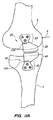
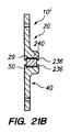
本発明の実施形態に従う、移植可能なブレースは、関節が形成される骨の少なくとも1つに接続するための構成要素のうちの少なくとも1つを含む。図1A〜図1Bは、膝疼痛を治療するために患者へ移植するための内部ブレース10の一実施形態の斜視図および断面図を図示する。ここで、本明細書に説明する具体的な実施形態は、患者の膝関節を治療するように適合されるが、それらは、指関節、足指関節、肘関節等が挙げられるがそれらに制限されない身体の他の関節を治療するようにも適合することができることが留意される。内部ブレース10は、大腿骨構成要素20および脛骨構成要素40を含む。大腿骨構成要素20は、患者の大腿骨の遠位端部分に取り付けられるように構成される。大腿骨構成要素20は、細長い柄部24を含む上部22を含む。大腿骨構成要素20は、下部が下方に延在すると、骨の間の関節内の間隙内に延在する顆状突起突出部28内に上部22から外向きにテーパになる下部26をさらに含む。顆状突起突出部28は、凸状の下部29を有する。顆状突起突出部28の上部表面30は、大腿骨の遠位端で患者から除去されている、大腿骨の顆状突起または大腿骨の顆状突起の一部に概して一致するように輪郭形成される。
An implantable brace according to an embodiment of the present invention includes at least one of the components for connecting to at least one of the bones to be articulated. 1A-1B illustrate perspective and cross-sectional views of one embodiment of an
上部22は、大腿骨に取り付けられるように構成された内部表面32および内部表面32が大腿骨に取り付けられ、内部ブレース10が移植されているときに、大腿骨の外側になる外側表面34を備える。
The
脛骨構成要素40は、患者の脛骨の近位端部分に取り付けられるように構成される。脛骨構成要素40は、細長い柄部44を含む下部42を含む。上部46は、それが下部から上方に延在すると、大腿骨構成要素20と脛骨構成要素40との間の相対的回転を可能にするように、下部42から外向きにテーパになり、顆状突起突出部28の凸状の下部29に係合するために、平坦な上部表面50を有する上部トレイ48を形成する。トレイ48の下部表面52は、除去されている脛骨プラトーまたは脛骨プラトーの一部分の輪郭に概して一致するように輪郭形成される。平坦表面として表面50を提供することによって、構成要素20および40が横軸2を中心として相互に対して回転することが可能になるだけでなく、それらは、長手方向軸4を中心として相互に回転することも可能になる。さらに、構成要素20および40は、少なくとも前後方向の相互に相対する並進をも可能にする。したがって、ブレース10は、表面50が凸状の表面29に一致する凹状の表面によって置換される場合に可能にするように、デバイス10が、歩行サイクルの屈曲および進展中に自然に生じる相対的長手方向軸の回転および前後方向の並進を制限しないように、膝の屈曲および伸展動作中に大腿骨および脛骨の相対的長手方向軸の回転および前後の並進を可能にする。
The
歩行サイクル中の長手方向軸回転および前後の並進から得られた接触表面29および50の位置の変更に対応するために、接触表面のうちの1つまたは両方(および支持構造の下層または上層)は、その別の部分よりも実質的に幅広い、その少なくとも一部分を有するように構成することができる。図1Dは、接触表面50の一実施例の上面図(または表面29の底面図)を図示し、それは、概して一定幅の後部50p、29pから、前端部50a、29aにおけるより幅広い部分までテーパになる表面の幅を示す。したがって、前部29a、50は、後部29p、50pよりも幅広い。図1Eは、接触表面50の別の実施例の上面図(または表面29の底面図)を図示し、それは、概して一定幅の前部50a、29aから後端部50p、29pにおけるより幅広い部分までテーパになる表面の幅を示す。したがって、後部29p、50pは、前部29a、50aよりも幅広い。代替的実施形態は、テーパの量、およびテーパが開始される表面の長さに沿った位置の変化を有し得る。図1Dの構成対図1Eの構成の使用は、ブレースが内側または外側上に移植されるかどうかによって異なり得る。接触表面39、50は、自然骨のうちの1つの接触表面が、自然骨のうちの別の接触表面に相対して通る軌道に一致するように湾曲し得、例えば、接触表面は、図1Fに図示するように、図1Aの直線1B−1Bに垂直である、平面における曲率を用いて形成され得る。この例において、他の湾曲した形状を使用し得るが、接触面は、半月板と同様に形成される。さらに、図1Fの直線1F−1Fに沿った図1Gの断面図によって図示するように、接触面は、図Fに示すものと垂直の平面等の他の平面で湾曲し得る。
One or both of the contact surfaces (and the lower or upper layer of the support structure) is to accommodate changes in the position of the contact surfaces 29 and 50 resulting from longitudinal axis rotation and back-and-forth translation during the walking cycle. , Having at least a portion thereof that is substantially wider than another portion thereof. FIG. 1D illustrates a top view of one embodiment of contact surface 50 (or a bottom view of surface 29) that tapers from a generally constant width
図1Cは、患者の膝の内部関節に移植された、図1A〜図1Bの内部ブレースの断面図である。図示のように、上部構成要素20は、患者の大腿骨6の外部表面に一致するように構成され、下部構成要素40は、患者の脛骨7の外部表面に一致するように構成される。さらにまたはあるいは、患者の大腿骨6および脛骨7の部分は、それらが、大腿骨6および脛骨7内に少なくとも部分的に陥凹され、かつそれに同一平面上になり得るように、柄部24および44を受容するように除去され得る。
1C is a cross-sectional view of the internal brace of FIGS. 1A-1B implanted in an internal joint of a patient's knee. As shown, the
構成要素20および40は、係止ネジ60および両皮質ネジ62を開口部21を通して、大腿骨6および脛骨7のそれぞれの骨内にネジ止めする等、ネジ等の1つ以上の締結具によって固定される。代替的締結具としては、動的ラグネジが挙げられるが、これに制限されない。さらにあるいは、上部および下部の柄部24、44のうちの1つまたは両方は、ブレードプレートとして形成され、説明する締結具のいずれかを使用して取り付けられ得る。大腿骨構成要素20の下部26を通るネジは、この部分の骨が一般的により強力であるため、重要な解剖学的ランドマークを回避し、かつより優れた滑車を達成するために、それらが、大腿骨6内にネジ止めされると上方に角度をつけ得る。同様に、脛骨構成要素40の上部46を通るネジは、下方に角度をもった曲線に沿ってネジ止めすることができる。内部ブレース10は、内側側副靭帯(図示せず)の下に移植可能である。
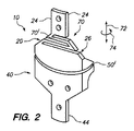
図2は、膝の疼痛を治療するために患者に移植するための内部ブレース10の別の実施形態の斜視図を図示する。この実施形態は、図1A〜図1Cの実施形態と同様であるが、それが大腿骨構成要素20に追従部材70を含む点で異なる。追従部材70は、上部24が、下部26に相対して軸方向に移動することができ、それによって大腿骨および脛骨が相互に相対的軸動作(即ち、矢印72の方向)の量を制限することを可能にするように、内部ブレース10の適合性を提供する。また、追従部材70は、骨との間の間隙が開閉するのを可能にし、それによって、健康な関節の軟骨の流体移動および負荷/除荷を模倣するように機能する。追従部材70は、上部24と下部26との間の相対的回転をさらに可能にし、それによって、デバイス10が、屈折および伸展中に自然に生じる相対的長手方向軸の回転を制限しないように、膝の屈折および伸展動作中に大腿骨および脛骨の相対的長手方向軸の回転の制限を可能にする。追従部材70は、負荷の少なくとも一部分を吸収し、かつブレースの載荷および負荷伝達特性を変更するように機能する。支柱70は、追従部材70によって提供された追従度の特性(例えば、軸方向または回転方向におけるバネ定数)を変化するように変化させることができる(例えば、支柱70の厚さおよび/または長さを変化させることによる)。
FIG. 2 illustrates a perspective view of another embodiment of an
図2に示すものの代替として、上部と下部との間の脛骨構成要素に追従部材を提供して、同様の効果を達成することができることが留意される。さらに、代替的に、または追加的に、追従部材を大腿骨構成要素と脛骨構成要素との間、例えば、接触表面29と50との間に提供することができる。追従部材70は、図1A〜図1Cの実施形態に組み込むことができることがさらに留意される。同様に、上部表面50′が上部20の凸状の下部表面に一致するように、上部トレイ48の凹状の上部表面50′を用いて図2の実施形態を提供するよりはむしろ、トレイ48の上部表面は、図1Aのものと同様の平面50として提供することができる。より具体的には、本明細書に説明する実施形態のそれぞれの特性は、それが実施不可能でない限り、他の実施形態の特性と組み合わせ可能であり、例えば、1つの特性は、他の特性の代替であり、したがって、その特性を置換するか、または置換もしくは組み合わせが実施形態を作動不能にする。
Note that as an alternative to that shown in FIG. 2, a tracking member may be provided in the tibial component between the upper and lower portions to achieve a similar effect. Furthermore, alternatively or additionally, a tracking member can be provided between the femoral component and the tibial component, for example between the contact surfaces 29 and 50. It is further noted that the tracking
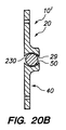
図3A〜図3Bは、膝の疼痛を治療するために患者に移植するための内部ブレース10の別の実施形態の斜視図および断面図を図示する。この実施形態は、図1A〜図1Cの実施形態と同様であるが、凸状の表面29を裏当てする追従材料76を含むという点において異なる。この追従材料は、エラストマー等の追従生体適合性ポリマーから作製されてもよく、負荷吸収のための軸受表面として機能する。負荷中、追従材料76は、圧縮する。したがって、追従材料76は、上部24と下部26との間の制限された相対的軸動作を可能にし、それによって、大腿骨および脛骨は、相互の制限された量の相対的軸動作が可能になる。また、追従材料76は、骨の間の間隙が開閉するのを可能にするように作動し、したがって、健康な関節の軟骨の流体移動および負荷/除荷を模倣する。この点に関して、追従材料材は、関節を形成する自然材料の追従性の差異をより綿密に模倣するようにモデリングされ得る。例えば、追従材料は、最も追従性のある(例えば、半月板を模倣する)追従材料の接触表面、中間追従性を有する(例えば、半月板から骨の移行を模倣する)中間部、および比較的に追従性があまり無い(例えば、半月板からさらに離れた距離でさらに圧縮する骨を模倣する)金属部材に実装される一部分と共に、異なる追従性を有するように形成され得る。図3Cは、移行追従性を有するように構成された追従部材76の一実施例を図示する。剛性部材20との接点から最も遠く、かつ接触軸受表面を含む部材76の部分76aは、最大の追従性を有し、金属上部部材20と接触する部分76cは、部材76の部分の最小の追従性を有する。部分76bは、76aより低い追従性を有するが、76cよりも高い追従性を有する。したがって、部材76は、接触表面を含む部分で提供される最大の追従性および金属構成要素20に向かう方向に移行的に減少する追従性を有する、移行追従性を提供する。移行追従部材は、それぞれ異なる追従性を有する3つの部分に制限されないが、2つの部分または3つ以上の部分を含んでもよい。さらにあるいは、移行追従部材は、それが取り付けられる位置から最も離れた位置から、それが取り付けられる部材と接触する表面までの一方向で連続して変化する追従性を有するように形成され得る。これらの実施例のいずれかにおいて、追従性の移行は、典型的に、移行追従部材が取り付けられる端部における最小の追従性から、移行追従部材が取り付けられる表面から最も離れた接触表面、またはその付近における最大追従性までの移行である。追従性の移行は、図3Cの実施例のように、異なる追従性特性を有する材料の代替、またはそれに加えて、変化する追従性を有するバネ部材、または他の機械的追従性部材を提供することによって達成される。
3A-3B illustrate perspective and cross-sectional views of another embodiment of an
図3A〜図3Cに示すものの代替として、追従材料を、トレイ48の上部表面50′(または50)上に提供して、同様の効果を達成することができることが留意される。追従部材70は、図3A〜図3Bの実施形態に組み込むことができ、かつ/または平坦表面50は、上述のように、可能ならば、異なる実施形態の特性が組み合わせ可能であるため、凹状の表面50の代替として提供することができることがさらに留意される。
It is noted that as an alternative to what is shown in FIGS. 3A-3C, a compliant material can be provided on the upper surface 50 '(or 50) of the
上部20および下部40の骨接触表面は、骨統合を強化するように構成されてもよい。骨統合強化剤としては、ヒドロキシアパタイトもしくは他のリン酸カルシウム組成物、骨形成タンパク質、コラーゲン、または他のタンパク質等の、骨の成長を強化させるために当該技術において周知であり、かつ使用される骨統合もしくは骨形成、粗面もしくは多孔質面、または他の治療を誘発する手助けとなることが証明されているコーティングが挙げられるが、それらに限定されない。図3Bは、上部柄部24および下部柄部44の骨接触表面上に提供される骨統合強化剤80を示す。しかしながら、上述の骨統合強化剤は、本明細書に説明するデバイスの任意の表面上に提供されてもよく、そこへの骨結合を強化させることが望ましい。
The bone contacting surfaces of the upper 20 and lower 40 may be configured to enhance bone integration. Bone integrity enhancers are well known and used in the art to enhance bone growth, such as hydroxyapatite or other calcium phosphate compositions, bone morphogenetic proteins, collagen, or other proteins Or, including, but not limited to, bone formation, rough or porous surfaces, or coatings that have been proven to help induce other treatments. FIG. 3B shows a
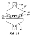
図4は、大腿骨6および脛骨7のそれぞれへの取り付けによって移植されているブレース10′の別の実施形態の図を図示する。この実施形態において、大腿骨6に取り付けられる上部20は、使用中に軸受表面および追従部材の両方として機能する、懸架追従部材90を含む。示すように、上部部材20は、三角構成で形成され、三角部材の2つの側面は、支柱92によって形成され、第3の側面は、懸架追従部材90である。上部は、例えば、上述の方法のいずれかによって、ネジ、および任意選択で骨統合強化剤80を使用して、懸架追従部材90に対向する部分93に沿って、大腿骨6に固定される。ここで、良好な構造的剛性を提供することで周知の、三角構成を使用する。しかしながら、1つ以上の支柱92が、これから説明するように機能するように、懸架追従部材90を大腿骨6に接続する、他の構成が代替的に使用されてもよい。
FIG. 4 illustrates a diagram of another embodiment of a
懸架追従部材90は、下部の脛骨構成要素40の上部表面50″と接触するときに、それが負荷下で屈曲するように機能するように、柔軟である。懸架追従部材90は、図4に示すように、大腿骨に取り付けられたときに、大腿骨6の遠位端6dから遠位に延在する。間隙または懸架距離94は、懸架追従部材90と固定位置93との間に存在する。歩行または走行負荷下で、懸架追従部材90は、大腿骨に向かって多少湾曲し、それによって、懸架追従部材90の少なくとも湾曲された部分の曲率半径を多少変化させるが、対向する軸受要素に対する摺動運動と干渉するほどを十分には変化させない。このようにして、懸架追従部材90は、軸受表面として機能し、骨の間の間隙が開閉し、それによって、健康な関節の軟骨の流体移動および負荷/除荷を模倣するのを可能にするように作用する。追従部材90の湾曲の範囲は、大腿骨/脛骨がデバイスの機能領域(載荷される場所)内に接触する範囲を決定する。追従部材90が湾曲すると、大腿骨および脛骨は、相互に近付き、増加した負荷を支える。したがって、大腿骨および脛骨によって支えられた増加した負荷は、追従部材90の湾曲量の増加に従い増加する。したがって、追従部材90は、上部20と下部40との間の相対的軸動作が生じることができるように、ブレース10′内に追従性を提供する。これは、順に、大腿骨6と脛骨7との間の相対的軸動作を可能にする。
The
構成要素20、40のうちの1つまたは両方は、図4において比較的垂直の矢印によって示す軸方向に調節され得る。これらの調節は、ブレースの負荷量の相対的変動をもたらす。また、例えば、図4に示すもの等の追従ブレース10の場合では、この種の調節は、追従部材によって提供される吸収量を、その上で離開が生じる最低量まで変更する。
One or both of the
非追従ブレース10の使用では、ブレースの軸方向の調節は、ブレースによる関節の離開量を調節する。これらの調節は、上部および下部構成要素がその中にネジ止めされる、大腿骨6および脛骨7上の位置を変更することによって行うことができる。あるいは、1つ以上の調節機構は、大腿骨6および脛骨7の固着位置を変化させる必要がないように、ブレース10内に提供されてもよいが、変更は、調節機構を変更することによって行うことができる。例えば、かかる調節機構の1つを図15に図示する。
In the use of the
懸架追従部材90は、1つ以上の支柱94に除去可能に固定される。したがって、懸架追従部材90は、必要に応じて、置換される部材と同一の仕様を有する懸架追従部材、または、置換されるものとは異なる曲率および/または異なる弾性曲げ係数を有する懸架追従部材のうちのいずれかを用いて、除去し、かつ置換することが可能である。1つ以上の支柱への懸架追従部材の除去可能な固定は、部材90の軸受機能を妨害しないように皿ネジであってもよい、ネジ96によって行い得る。
The
下部40は、図4に示すように、ブレース10′が移植されるときに、脛骨7に固定される。固定された基部103は、基板103を脛骨7の骨に固定するように、ネジ止めされる(および任意選択により、骨統合強化剤80を使用してもよい)。対向軸受部材100は、懸架追従部材90に対向し、基部103に除去可能に取り付けられる。対向軸受部材100は、図4に示すように、下部40が脛骨に取り付けられるときに、脛骨7の近位端7pの近位に延在する。歩行または走行負荷下で、対向軸受部材100は、それが懸架追従部材90に対して乗せられ、相対的にそこに摺動するため、湾曲しない。さらに、対向軸受部材100の表面50″が平坦またはわずかに凸状であるため、軸受100と懸架追従部材90との間の相対的回転も可能になる。したがって、これにより、上部(大腿骨)構成要素20と下部(脛骨)構成要素40との間の相対的回転が可能になる。これにより、デバイス10が、歩行サイクル中の屈曲および伸展中に自然に生じる相対的な長手方向の軸回転を制限しないように、膝の屈曲および伸展動作中の大腿骨および脛骨の相対的長手方向の軸回転を可能にする。
The
対向軸受部材100は、生体適合性金属、合金、または硬質の熱硬化性ポリマー等の比較的剛性材料から作製される。対向軸受部材100は、蟻継ぎ104および/または、1組以上のネジ106が挙げられるが、それらに限定されない固定方法によって、基板103に除去可能に取り付けられる。さらにまたはあるいは、患者の大腿骨6および脛骨7の部分は、それらが大腿骨6および脛骨7内に少なくとも部分的にくぼみが付けられ、それと同一平面にさえなり得るように、基板93、103、および支柱92の部分(および任意選択で、軸受100)を受容するように除去されてもよい。
The
固定された基部93が大腿骨6に固定される定置/位置は、膝関節の歩行サイクルのすべてまたは一部のみが支持されているかどうかによってブレースを調節するために、大腿骨6の長手方向軸に相対して前/後方向(矢印95)、ならびに角度的(矢印97)の両方において、変化し得る。例えば、図4において、大腿骨6に相対的に、上部90を時計回りに回転させ、かつ固定された基部を左に並進させる一方、下部40を示す位置に固定させたままにすることによって、ブレース10は、完全伸展(示す構成)の膝を支持しないが、膝が部分的および/または完全屈曲にある歩行サイクルの少なくとも1部分中に支持されるように構成される。逆に、上部の相対的位置は、完全伸展のみの関節を治療するように固定することができる。さらに相対的固定位置を使用して、膝関節が支持される間の歩行サイクルの量、ならびに支持される歩行サイクルの様々な部分(またはすべて)において提供される相対的支持量をカスタマイズすることができる。
The placement / position where the fixed
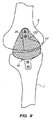
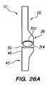
本明細書に説明するすべての他のブレースと同様に、図4のブレース10′は、左膝または右膝の、膝の内側または膝の外側のいずれかの上に移植することができる。さらに、本明細書に記載するブレースは、一対(膝の内側に1つ、および膝の外側に1つ)で移植することができる。図5は、上記の図4に関して説明した種類のブレース10′が、膝の内側上に移植され、上記の図4に関して説明した種類の別のブレース10′が膝の外側上に移植される、両画分システムを図示する。大腿骨6および脛骨7の軸受表面の間の接触により画定される通路が、外側上と内側上では同一ではないため、外側上のブレース10′の上部20(想像線)は、伸展から屈曲し、再度伸展に戻る通常の歩行サイクルの外側画分と比較して内側画分に沿った異なる通路に対処するように、内側上のブレース10′の上部20(実線)の定置の正反対に定置されない。外側上の脛骨に相対する大腿骨の並進は、内側上の並進よりも大きい。これは、大腿骨6と脛骨7との間の相対的軸回転、およびデバイス10の軸受表面がそれに沿って相互作用する異なる接触通路を含む、膝の複雑運動をもたらす。膝の回転は、中心の枢動軸に沿わないが、さらにより複雑であり、内側および外側は、大腿骨6と脛骨7との間の相対的回転中に異なる量の外側の摺動を経験する。本発明のブレースは、一対のブレースが、膝の内側に一方、および膝の外側に他方が設置されるときに、これらの差異に対応するように定置することができる。したがって、図5における膝の外側上のブレース10′の上部20の回転軸は、歩行サイクル中に通った異なる経路に対応するために、膝の内側上のブレース10′の上部20の回転軸に相対して前後方向にずらされてもよい。図5において、下部40は整列しており、このため、外側ブレースの下部20は図5では見えない。
As with all other braces described herein, the brace 10 'of FIG. 4 can be implanted either on the left or right knee, either inside the knee or outside the knee. Further, the braces described herein can be implanted in pairs (one on the inside of the knee and one on the outside of the knee). FIG. 5 shows that a
内側画分および外側画分の異なる経路は、膝の内側および外側上の相対的に異なる対向位置に定置された同一の種類のブレース10によって対応されてもよい。あるいは、異なる種類のデバイス10を、膝の内側および外側のそれぞれの上に使用してもよく、異なるブレース10は、2つの側面に必要とされる異なる経路に対応するように設計される。この場合、かかるブレース10は、膝の内側と外側との正反対の位置に移植されてもよく、依然として、それぞれの内側および外側上の異なる運動経路に対応する。さらにあるいは、異なる種類のブレース10は、異なる経路の要件に対応するように、内側および外側上の相対的に異なる対向位置に移植することができる。
Different paths of the inner and outer fractions may be accommodated by the same type of
図6は、内部ブレースの外表面が、図6に示すように、大腿骨6および脛骨7の骨表面と実質的に同一平面になるように、柄部24および44を少なくとも受容するように患者の大腿骨6および脛骨7が除去される方法で、膝関節において大腿骨6および脛骨7に取り付けられた内部ブレース10を図示する。任意選択で、大腿骨6および脛骨7上の顆状突起および/または軟骨の部分は、より高い安定性のために突出部28、48の部分を少なくとも受容し、かつ/または損傷または罹患した骨を除去するために除去されてもよい。さらに、突出部28、48のうちの1つまたは両方の少なくとも一部分の除去は、これらの形状をブレース10の構成要素で覆うことによって、さらなる厚さが追加されないように、膝の自然整合を維持するために実施し得る。軸受表面76は、示すように、下部(脛骨)構成要素40の上部表面上に定置されるが、代替的に、大腿骨(上部構成要素)20の底部軸受表面に定置されてもよい。軸受表面76は、エラストマー等の追従性生体適合性ポリマーから作製されてもよく、軸受表面として機能し、骨の間の間隙が開閉するのを可能にし、したがって、健康な関節の軟骨の流体移動および負荷/徐荷を模倣するように作用する追従材料を備える。負荷中、追従材料76は、圧縮する。したがって、追従材料76は、軸受表面が接触した後でさえ、上部20と下部40との間の相対的軸動作の制限を可能にする。
FIG. 6 shows the patient receiving at least the
この場合において、上部20および下部40の基板は、圧縮ネジ64を使用して、大腿骨6および脛骨7のそれぞれに固着される。上部20を大腿骨6に取り付ける圧縮ネジ64は、圧縮ネジ64が、大腿骨6の長手方向軸L1に垂直である水平線P1から上方に角度付けて、角度的に上方向に上部20から離れて向くように、角度的に上方向に大腿骨内にネジ込まれ得る。下部40を脛骨7に取り付ける圧縮ネジ64は、脛骨7の長手方向軸L2に垂直である水平線P1から上方に角度付けて、圧縮ネジが角度的に上方向に上部20から離れて向くように、角度的に下方向に脛骨内にネジ込まれ得る。
In this case, the upper 20 and lower 40 substrates are secured to the
内部ブレース10が骨表面と同一平面になるか、または、少なくとも骨6および7の外表面に単に取り付けられたブレースより低く表面から延在するように、内部ブレース10を骨6、7内に少なくとも部分的に差し込むことによって、内部ブレース10が、ほとんど内側靭帯に対する障害物ではなくなる。その結果、内部ブレース10は、内側靭帯に合併症をもたらすことなく、内側靭帯の下により容易に移植される。また、内部ブレース構成要素の相対的運動は、刺激するか、さもなければ、内側靭帯または他の軟組織構造に関連する問題をもたらす可能性が少ない。したがって、これは、低プロファイル移植をもたらし、それは、皮膚の刺激を少なくし、かつ他の軟組織への刺激を少なくする。
The
図7Aは、本発明に従う、内部ブレース10の別の実施形態を図示する。この実施形態において、上部20および下部40の大半は、大腿骨6および脛骨7のそれぞれの中に移植される。したがって、上部部材20および下部部材40の内部に移植された部材110のそれぞれの小さな近位端部分のみが骨6、7の外部になる。部材110は、髄内釘と同様であるか、または他の軸方向に非圧縮性であるが、それは、それらの軸非圧縮性により、柱強度を提供するが、部材が、それらがその中に移植される大腿骨6および脛骨7のより良く構造的に支持する骨の輪郭に従うのを可能にする、柔軟(曲げ可能)な部材110である。露出した近位端部分は、除去可能な軸受構成要素114および116がそこに除去可能に取り付けられるのを可能にするソケットまたは他の接続特性112を含む。構成要素114、116は、剛性であり、一般的に、それらが嵌め合う顆状突起および軟骨の輪郭に従う。任意選択により、大腿骨6および/または脛骨7の軟骨および/または顆状突起の少なくとも一部分は、それぞれの軸受構成要素114、116が切り出された凹部内に受容されるのを可能にするように除去され得る。構成要素114、116の軸受表面は、非圧縮性(例えば、金属)であり得るか、あるいは、これらの表面のうちの少なくとも1つは、いくつかの軸移動を可能にするように追従であり得る。部材110は、典型的に、皮質骨を介して入口孔を開けた後に、それぞれの骨6および7内に挿入される。部材110を中に挿入することによって、圧縮嵌め合いが形成され、治癒とともに、骨は、骨統合強化機能80のいくつかの形態で典型的に提供される部材110内に成長する。
FIG. 7A illustrates another embodiment of an
図7B〜図7Fは、図7Aの実施形態に使用することが可能な、軸方向に剛性であるが、曲げ可能な部材110の様々な実施形態の部分図を概略的に図示する。図7Bにおいて、部材110は、残りの金属が、軸方向に沿って一連の相互接続するIビーム形状を形成し、したがって、管を相対的に軸方向に非圧縮性にさせるように、その中に形成された切り出し118を有する金属管(例えば、ステンレス網、チタン、チタン合金等)である。しかしながら、切り出し118は、矢印の方向の曲げを可能にする。
7B-7F schematically illustrate partial views of various embodiments of an axially rigid but
図7Cにおいて、部材110は、軸方向に非圧縮性であるが、柔軟性(曲げ可能)であり、それによって、軸非圧縮性による柱強度を提供するが、それらがその中に移植される大腿骨6および脛骨7のより優れた構造的に支持する骨の輪郭に従うように部材110が曲がるのを可能にする、非圧縮性バネ110を備える。
In FIG. 7C,
図7Dにおいて、部材110は、軸方向に非圧縮性であるプロファイルロッドまたはノッチロッド110rを備え、ノッチ110nは、部材110が軸方向の非圧縮性による柱強度を提供するが、それがその中に移植される骨のより良い構造的に支持する骨の輪郭に従うように曲がるように、いくらかの曲げが行われるのを可能にする。
In FIG. 7D, the
図7Eにおいて、部材110は、軸方向に非圧縮性であるが柔軟(曲げ可能)である柱またはシリンダーを形成し、それによって軸方向の非圧縮性により柱強度を提供するが、部材110が、それがその中に移植される骨のより良い構造的に支持する骨の輪郭に従うように曲がるのを可能にする、複数の連結された環110iを含む、連結環の組立体を備える。
In FIG. 7E,
図7Fにおいて、部材110は、軸方向に非圧縮性であるが、柔軟(曲げ可能)であり、それによって、軸方向の非圧縮性により柱強度を提供するが、部材110がそれがその中に移植される骨のより良い構造的に支持する骨の輪郭に従うように曲がるのを可能にする、ジッケルロッド110zを備える。
In FIG. 7F,
図8は、歩行サイクルの1つ以上の部分中に支持を提供するように、特注構成することができる、ブレースを図示する。示すように、上部軸受部分122は、示すように、膝関節が伸展しているときに、下部の軸受部分124に相対して、接触し、摺動する(および、任意選択で回転を可能にする)ように構成される。歩行サイクル中、膝が曲がり、脛骨7が、示すように、図8の脛骨6に相対的に時計回りに回転すると(図8において右側にある膝関節の前部分)、部分122および124の軸受表面は、部分122および124がもはや整合されていないため、屈曲が生じるまで、もはや相互に接触することができない有意な範囲まで相互に相対して摺動する。したがって、歩行サイクルの屈曲相の後半部分中に、図8で構成されるように、ブレース10′は、上部および下部構成要素20、40が歩行サイクルのその部分の間に相互に接触しないため、膝関節を離開しない。
FIG. 8 illustrates a brace that can be custom configured to provide support during one or more portions of the walking cycle. As shown, the
上部軸受部分122は、蟻継ぎ104および/または1対以上のネジ106が挙げられるが、それらに限定されない固定方法によって、上部基部126(ネジ、および任意選択で1つ以上の骨誘導促進剤を使用して骨6に固定される)に除去可能に取り付けられる。このようにして、上部軸受部分は、それを同一設計の上部軸受部分と置換することによって既存の上部軸受部分122に関連する機械的問題に対処するだけでなく、代替的に、別の軸受部分122′(想像線で示す)は、ブレース10′が、歩行サイクルの異なる部分にわたり、膝関節を支持させるように収納され得るように、除去し、かつ置換することができる。例えば、示す部分122′は、歩行サイクルの屈曲部分に向かってより離開し、図8に示す伸展構成にあるときに、膝を支持しない。さらに代替的に、下部40の軸受部分124は、例えば、図8に示すように、前方ではなくむしろ、後方に延在するように(想像線で示す)異なって構成され得る。124または124′を使用するかどうかの判断は、124および124′が覆う脛骨の顆状突起のこれらの部分を被覆する軟骨の状態によって、少なくとも部分的に影響され得、より損傷した部分を覆うのが好ましい可能性がある(または、それを除去し、124または124′で置換する)。あるいは、ブレース10は、一時的または周期的療法として使用し得、軸受部分122が単に除去され、置換され、交換される必要があるため、それによって、離開は、骨または骨接触構成要素の連続的破壊なく印加し、かつ除去し得る。さらに、任意選択で、下部軸受部分は、完全な軸受表面であってもよく、該部分は、124および124′の両方によって示す領域を占める。
The
先述のように、ブレース10を使用して、関節の一時的な完全離開を提供し得る。例えば、軸受部分122および124は、通常、運動域にわたり相互に接触する骨の自然な軸受表面が全く接触しないが、何ら負荷を負担する必要がなく治癒するのを可能にするように、可動域の全範囲にわたり骨を離開するように構成し得る。一時的期間が終了した後、軸受表面122は、運動域の少なくとも一部分にわたり、自然な軸受表面への少なくとも部分的な負荷を可能にするように設計された、異なって構成された軸受表面と置換することができる。さらに、代替的に、軸受部分122および/または124、または全体のブレース10は、一時的期間が終了した後に除去し得る。一時的期間は、自然の軸受表面への損傷の範囲および種類、個人の患者の特徴等によって異なる可能性がある。一実施形態において、一時的期間は、約3ヶ月である。別の実施形態において、一時的期間は、約3〜6ヶ月である。しかしながら、この方法は、それが、任意の一時的な時間の長さで実行することができるため、いかなる特定の一時的期間にも限定されず、一般的に、自然接触/軸受組織の最適な治癒を提供するのに必要とされる、おおよその時間によって決まる。
As previously described, the
図9は、相互に接触し、かつ軸受表面として機能する部分の接触表面を少なくとも封入するシース130を用いて提供されるブレース10′を図示する。示す実施例において、ブレース10′は、図8に示す種類であるが、本明細書に説明する任意の他の実施形態は、シース130を用いて同様に提供することができる。構成要素20および40が、それぞれ、骨6および7に固定された後に、シース130は、軸受表面を少なくとも被覆するようにブレース10′に固定される(図9に示す実施例において、全体の上部がシース130によって被覆されることが留意される)。シース130は、内側靭帯および他の軟組織と接触する平滑表面を提供し、それによって、特に一方の他方に相対する動作中に、構成要素20、40のうちの1つの上で摩擦することによって内側靭帯および他の軟組織が損傷するリスクを大幅に減少させる。時間とともに、シース130は、ブレース10/シース130が移植される身体の治癒反応の結果として、自然組織によって封入され得る。任意選択で、シース130は、ポリ乳酸ポリマー、ポリグリコール酸ポリマー、そのコポリマー等の生体吸収性材料、またはシースを構築するのが可能である他の生体適合性の生体吸収性材料から形成されてもよい。少なくとも1つの実施形態において、歩行サイクルの任意の相において内側靭帯の根底にある、少なくともブレース10′の部分は、内側靭帯とのより円滑界面を提供するように、シース130によって被覆される。さらに、代替的に、シース130は、構成要素20および40を骨に固定する前に、少なくともブレース10′の軸受表面を完全に封入するように、事前に設置され得る。この場合では、構成要素20および40のうちの1つまたは両方のネジ孔が、シース130によって被覆される場合、ネジは、骨6、7への構成要素20、40の取り付け中に、シース130を介してネジ込まれてもよい。さらに、代替的に、シース130は、ネジが、設置中にシース130を通してネジ込まれる必要がないように、柄部分ではなく、上部および下部構成要素20、40の顆状突起部分のみを封入し得る。シース130は、ブレース10の軸受表面から生成されたあらゆる摩耗粒子を捕獲し、単離するように設計され得る。シース130は、構成要素20、40上にスナップ嵌めされるか、またはネジ止めされ得る、および/または他の機械的および/または接着手段によって固定され得る。シース130は、内側靭帯との接触のための潤滑表面を提供するために、ポリテトラフルオロエチレンまたは拡大ポリテトラフルオロエチレンを含み得る。他の選択肢としては、ポリテトラフルオロエチレン、拡大ポリテトラフルオロエチレン、または他の生体適合性の潤滑材料を伴う、または伴わない、シリコーン、ポリエチレン、ナイロン、および/またはそれらの組み合わせが挙げられる。
FIG. 9 illustrates a
図10Aは、軸受表面およびテーパ部分26、46が、先述の実施形態よりもさらに膝関節内に延在する内部ブレース10の一実施形態を図示する。即ち、顆状突起部分28、48は、単に、骨を6および7を相互から離して離開するために大腿骨6および脛骨7の顆状突起部との間にくさびを形成しないが、図10Aの顆状突起部分28、48は、実際、内側(または、ブレース10が設置される側面によっては外側)上の骨を被覆する軟骨の幅の少なくとも4分の1を被覆するように、大腿骨6および脛骨7の顆状突起部の間の関節内に延在する。あるいは、上述のように、軟骨は、顆状突起部分46および/または26を覆う前に除去することができる。これらの顆状突起部分26、46は、膝関節の1つの側面上の軟骨の幅の最大約半分、もしくは最大3分の2、4分の3、または1つの側面上の軟骨の全体幅にまで延在し得る。顆状突起部分28、48は、既に上記に説明した方法のうちのいずれかで、相互に相互作用する軸受表面を含む。
FIG. 10A illustrates one embodiment of an
顆状突起部分28、48を含むテーパ部分26、46は、上部および下部20、40の固着部分24、44に除去可能に取り付けられる。例えば、部分26、46のそれぞれは、重ね継ぎ手140およびネジ142、または構成要素をともに係止することができる他の機械的固定を介してそれぞれの部分24、44に固定され得るが、構成要素26、46の除去および置換を可能にするように逆転することもできる。このようにして、構成要素26、46のうちの1つまたは両方は、機械的欠陥等を修正するための同様の構成要素によって置換することができる。あるいは、構成要素26、46は、それらが膝関節内に延在する距離を変更するために、比較的短いまたは長い軸受表面を有する構成要素26、46によって置換することができる。固定部分24および44は、それぞれ、係止ネジ、圧縮ネジ、両皮質ネジ、および/または骨統合特性の使用が挙げられるが、それらに限定されない、上述の固定部材および技術のうちのいずれかによって大腿骨6および脛骨7に固定され得る。
図10Bは、図10Aの配列の構成要素26、46が除去され、かつ、図10Bに示す部分26′、46′で置換された後の図10Aの実施形態を示し、該部分は、それらが、軟骨を被覆する位置で膝関節内に延在しないが、前述の実施形態に関して図示し、かつ説明した方法と同様にそれらを離開するために、大腿骨6と脛骨7との間にくさびを形成するように、さらに短い軸受表面を有する。
FIG. 10B shows the embodiment of FIG. 10A after the
図10A〜図10Bに示したものによって例示するように、内外方向の軸受表面の寸法を変更するのに加え、またはその代替として、前後方向の軸受表面の寸法は、図10C〜図10Dに図示するように、変更することができる。図10Cは、膝関節内に設置されたブレース10の側面図を図示し、そこでは、構成要素26′が大腿骨の顆状突起にわたり完全に後方に延在するが、大腿骨の長手方向軸の前方のほんのわずかな距離のみ延在する。同様に、構成成分26′は、その軸受表面が脛骨の顆状突起の後方端付近に延在し、構成要素26′が脛骨の長手方向軸のわずか前方のみに延在するように、後方に延在する。図10Dにおいて、構成要素46′は、その脛骨の長手方向軸を越える後方および前方範囲において、ほぼ対称であり、構成要素26は、大腿骨の顆状突起の後方端部分上のみに提供される。この配列において、構成要素26′の軸受表面と46′の軸受表面との間の接触は、歩行サイクルの屈曲構成要素の終了に近づくにつれて生じる。歩行サイクルの別の部分(示すように、伸展を含む)において、構成要素46′の接触表面は、構成要素46′が関節の間隙内に延在する場合に、図10Dに示すように、大腿骨の顆状突起の自然軟骨に接触する。
In addition to or as an alternative to changing the dimensions of the bearing surfaces in the inward and outward directions, as illustrated by those shown in FIGS. 10A-10B, the dimensions of the front and rear bearing surfaces are illustrated in FIGS. 10C-10D. Can be changed. FIG. 10C illustrates a side view of the
図11Aは、先述の実施形態と同様に、除去可能に取り付けられた部分26および46のうちの1つまたは両方が、1つ以上の損傷部分を除去するために置換することができ、それによって、デバイス10′を補修するか、または、代替的に、部分26、46のうちの1つまたは両方が、歩行サイクルの1つ以上の部分にわたり、ブレースによる支持を変化させるように構成された異なる設計の部分26、46によって置換することができるように、除去可能に取り付けられた部分26および46を含む、ブレース10′の一実施例を示す。
FIG. 11A shows that, as in the previous embodiment, one or both of the removably attached
基部(即ち、大腿骨構成要素20の上部22および脛骨構成要素40の下部42)は、それぞれ、大腿骨6および脛骨7に固定され、かつ、典型的に、部分26および46のうちの1つまたは両方が置換されるときに、除去されず、かつ置換されない。基部22および42は、一般的に、それらが固着される大腿骨6および脛骨7の骨の輪郭に従うように成形され得る。図11Cは、図11Aの骨6に取り付けられて示される位置で骨6の輪郭に概して従い、かつ嵌め合うように、成形された構成を用いて製造される部分22の前面図(即ち、図11Aの矢印Aの方向からの矢視)を図示する。この同様の方法は、脛骨7の輪郭が、大腿骨6の輪郭と概して同一ではないため、図11Aの骨7に取り付けられて示される位置で骨7の輪郭に概して従い、かつ嵌め合うように設計された異なる輪郭を典型的に有するが、部分42に適用することができる。
The base (ie,
あるいは、部分22および42のうちの1つまたは両方は、任意の表面輪郭(これが製造するのに最も好都合であり、かつそれが固着されている骨の輪郭に嵌め合うように部分を変形する、最良の開始立体構造でもあるため、典型的には、図11Bと同様の概して平坦または平面の表面輪郭)を用いて形成することができ、かつ上下方の軸4に沿ってそれを一般的に剛性にさせる機械的特徴を有し、かつ一般的に、全体を通して強固である。しかしながら、曲げ工具を使用するか、または部分22または46が、それぞれ、大腿骨6または脛骨にネジ止めされるときに印加された圧縮力および曲げ力は、ネジによって、部分22または42を変形させて、それが固着されている骨の輪郭に、概して従うことができる。したがって、部分22の場合では、ネジを開口部21を通して部分22に対して、かつ骨6内にネジ込むことによる、大腿骨6への固着部分22の作用により、部分が概して図11Cに示す形状と同様の形状に変形する。部分22、42が剛性か、または変形可能であるかどうかに関わらず、それらは、示すように、それらがそれぞれの骨に接触するこれらの部分内への骨内部成長を促進するように、骨統合促進機能80と共に提供される。
Alternatively, one or both of the
図12は、外側支持のために膝関節の外側に移植された内部ブレースを図示する。この構成において、大腿骨構成要素の上部22は、上述のいずれかの方法で、係止ネジ60、圧縮ネジ64および/または両皮質ネジ62を使用して、外側上の大腿骨6に固定される。1つ以上の骨統合機能/被覆もまた、上述の方法で使用されてもよい。一実施形態において、脛骨構成要素は、ボルト、ロッド、釘、ネジまたは支柱66をそこを通過させて、かつそれらを、それによって脛骨7の内側に固着される第2の脛骨基質150に接続することによって脛骨に固着される。内側基質150は、事前成形される剛性基質として提供し得るか、または、骨7に圧力を印加するために、基質150および42を相互に向かって引き出すためにボルト、スタッド、釘、ネジ、またはロッド66が使用されると、内側上の脛骨の輪郭に従うように変形され得る。同様に、基部22および42は、剛体であり、かつ輪郭を用いて事前に構成され得るか、または図11A〜図11Cに関する上述の方法で変形可能であり得る。
FIG. 12 illustrates an internal brace implanted outside the knee joint for external support. In this configuration, the
任意選択で、内側基板160(図12において、想像線で示す)は、大腿骨構成要素20を固着するために使用されてもよい。
Optionally, an inner substrate 160 (shown in phantom in FIG. 12) may be used to secure the
図13は、図12に関して説明する種類の内部ブレース10が膝の外側上に移植され、図12に関して説明する種類の別の内部ブレース10が膝の内側上に移植される、両画分システムを図示する。図12と同様に、外側上のブレース10の脛骨構成要素40は、この実施例においては、内側ブレース10の脛骨構成要素40の基部42である内側基板に固着される。任意選択で、内側軸受表面にさらなる支持を提供するために、圧縮ネジ64または係止ネジ60をさらに使用して、内側脛骨構成要素40を固定し得る。大腿骨構成要素20の両方は、図12に関して説明する方法で固着されてもよい。あるいは、内側大腿骨構成要素の上部22は、ボルト、釘、ネジ、スタッド、または大腿骨6を通して延在するロッド66によって接合されるように上方に延在し、かつ外側大腿骨構成要素20に接続されてもよい。
FIG. 13 illustrates a two-fraction system in which an
図14は、大腿骨部分20の軸受表面29が、1つ以上(好ましくは、複数)の玉またはころ軸受170により提供される、ブレース10′の一実施形態を示す。代替的には、脛骨構成要素40の対向軸受表面50は、1つ以上の玉またはころ軸受170により提供することができる。さらに、脛骨構成要素は、上述のように、歩行サイクル中に大腿骨6と脛骨7との間の相対的軸回転を可能にするように、回転軸受172と共に提供されてもよい。さらに、任意選択で、追従部材および/または吸収材90が、上部20と下部40との間の相対的軸運動が生じ、骨の間の間隙が開閉することを可能にするように作用し、それによって、健康な関節の軟骨の流体移動および負荷/除荷を模倣するように、ブレース10に追従性を提供するために、表面50の下方、または表面29の上方のうちのいずれか(または両方)に提供されてもよい。それにより、ブレース10′が膝関節を支持するために移植されたときに、大腿骨6と脛骨7との間の相対的軸動作も可能になる。
FIG. 14 illustrates one embodiment of a
図15は、軸方向長さ調節機能と共に提供される、内部ブレースの一実施形態を図示する。ナット180は、それが回転するのを阻止するような方法で大腿骨構成要素の下部26内に受容される。柄部分24は、下部26内に形成されたチャネル182内で収縮自在に受容され、柄部24およびナット180を通過するネジ184の間のネジ込み接続によってそこに接合される。そこに隣接する一対の肩部186(ネジ頭184の上に1つ、およびネジ頭の下に1つ)によって、ネジ184が柄部分24から後退するか、または柄部24内に前進するのを防止する。柄部分124が下部26から延在する距離は、ネジ184を回転させることによって調節することができる。ネジ184が回転するときに、ナット180は、回動しないため、一方向のネジ184の回転は、柄部分24を下部26内にネジ込み、それによって、柄部分が延在する距離を短縮し、反対方向のネジ184の回転は、柄部分24を下部から引き出し、それによって、柄部分24が延在する距離を延長する。ブレース10が膝関節の内側に移植されるときに、柄部24が部分26から延在する長さを増大させることによって、大腿骨6と脛骨との間の離開量が増大する。反対に、部分26から延在する柄部24の長さを短縮することによって、大腿骨6と脛骨7との間の離開量が減少する。あるいは、調節機構180、182、184、186は、下部の柄部42および脛骨構成要素40内に提供することができる。任意選択で、追従部材90および/または吸収材は、上述と同様の方法で追従性を内部ブレースに追加するために提供し得る。
FIG. 15 illustrates one embodiment of an internal brace provided with an axial length adjustment feature. The
図16Aは、大腿骨6および脛骨7内に髄内移植されている内部ブレース10を図示する。この実施形態において、柄部分22および42は、実質的にロッド形状であり、例えば、それらが、それぞれ、大腿骨または脛骨の髄質管内に挿入され、かつ締まり嵌めによって固着される、腰移植のシャフトと同様に機能する。さらに、1つ以上の骨誘導機能80が、骨内部成長を促進するために、シャフト22、42の表面上に提供されてもよい。したがって、移植されると、大腿骨および脛骨構成要素は、相互に接触する、膝関節の中央の接触表面190および192を提供し、かつ大腿骨6および脛骨7を離開する。大腿骨接触表面190は、図16Bに図示するように、細長い(前後方向に沿った)凹状鞍形状を有し得、脛骨接触表面192は、内外方向の接触表面190の凹状形状に一致するように、前後方向に凸状であるが、前後方向に沿って直線(平坦)であり得る。
FIG. 16A illustrates the
図17は、大腿骨6および脛骨7内に髄内移植されている内部ブレース10の別の実施形態を図示する。この実施形態において、図16Aの実施形態と同様に、柄部分22および42は、実質的にロッド形状であり、例えば、それらが、それぞれ、大腿骨または脛骨の髄質管内に挿入され、かつ締まりばめによって固着される、腰移植のシャフトと同様に機能する。さらに、1つ以上の骨誘導機能80は、骨内部成長を促進するために、シャフト22、42の表面上に提供し得る。移植されると、大腿骨および脛骨構成要素20および40の部分26および46は、膝関節の中央の接触表面200および202を提供する。接触表面200および202は、個別の軸受表面であり、それらのそれぞれは、中間関節部材204上に提供された対向軸受表面のうちの1つと相互作用する。中間関節部材204は、球関節であってもよく、または図17に示すものと同様の卵形または楕円形の断面を有してもよく、剛性または追従性であってもよい。接触表面200および202は、中間関節部材204の対向表面の曲率に概して従うように凹状である。
FIG. 17 illustrates another embodiment of an
図18は、接触表面29および50が相互に接触して、規定量ほど大腿骨6および脛骨7を離開する内部ブレース10の別の実施形態を図示する。先述の実施形態と同様に、接触表面50に相対する接触表面29の形状は、表面29および50が、歩行サイクル中に行われる動作中に、大腿骨6と脛骨7との間の相対的軸回転をある程度可能にすることができるような形状である。さらに、表面29および50の形状および/または寸法は、それらが、歩行サイクルの規定部分のみにわたり離開/支持を提供するような形状および/または寸法である。示すように、接触表面29、50は、ほぼ、示す角度212のみを介して相互に接触し、その角度は、この実施例において、約0度(示すように、伸展状態の歩行サイクル)〜約45度である。勿論、この範囲は、記載のように、異なる可能性がある。また、支持を提供するその部分にわたり提供された離開量は、カム表面として支持表面29および/または支持表面50を形成することによって異なる可能性があり、その曲率半径は、それが前後方向の対向表面に対して回転するに従い変化する。示すように、表面29は、凸状表面であり、表面29は、それが、運動(歩行サイクル)中に、大腿骨6と脛骨7との間の相対的軸回転を阻止しないように、平坦であるか、またはほんのわずかに凹状である。
FIG. 18 illustrates another embodiment of the
大腿骨構成要素20の下部28は、大腿骨構成要素がそこに設置されるときに、大腿骨6の長手方向軸を横断して配向されるカット部210を含む。図18に示すように、カット部210は、実質的に大腿骨6の長手方向軸に垂直である。カット部210は、歩行または走行中に、いくつかの追従性をシステムに提供して、接触表面29と大腿骨の遠位端との間の距離が変化するように、構成要素20の屈曲および/または圧縮を可能にする。
The
上部20および下部40のうちの1つまたは両方は、低プロファイル構成要素として提供することができる。示す実施例において、構成要素20、40の両方は、低プロファイルである。それぞれの構成要素は、いくつかの先述の実施形態に提供される柄部が欠如する。それぞれの構成要素は、それぞれ、それが陥凹部214の上および陥凹部216の下に挿入されると、内側側副靭帯にクリアランスを提供する(図18は、内側上に設置されたデバイス10を示す)、陥凹部214、216を有する。
One or both of the top 20 and bottom 40 can be provided as a low profile component. In the embodiment shown, both
脛骨7および大腿骨6が、膝関節の屈曲および伸展動作中にそこを中心として回転する、膝関節の回転中心、または「枢動部」は、大腿骨6と脛骨7との間の接触表面上ではないが、その上方および大腿骨6の長手方向軸の若干前方に位置する。図19A〜図19Cは、構成要素の相対的回転が、膝関節の上方、好ましくは、膝関節の回転中心付近または膝関節の回転中心で生じる、内部ブレース10の一実施形態を図示する。示すように、上部構成要素20は、軸受表面として機能する結節26を備える。典型的に、結節26は、球面を有し、球関節と同様に機能する。テーパ支柱220は、結節26から延在し、圧縮嵌め合いを提供するために、大腿骨6内に穴あけされた孔内に駆動されるように構成される。支柱220は、上述の種類の1つ以上の骨統合機能80と共に、任意に提供され得る。大腿骨構成要素20の上部22は、結節26から延在し、ネジ(係止ネジ60、圧縮ネジ64、および/または両皮質ネジ62)がそこを通して大腿骨6内にネジ込まれ、さらに結節26を固定することができ、かつ大腿骨6に相対する結節26の回転も阻止する開口部を提供し、図19Bの部分的断面図を参照する。
The center of rotation of the knee joint, or “pivot”, about which the
この実施形態において、脛骨構成要素40は、その下の内側側副靭帯にクリアランスを提供するための陥凹部216を含む。脛骨構成要素40の上部46は、図19Aに示すように、設置されたときに膝関節にかかり、膝関節にわたり脛骨7に固定される脛骨構成要素の基板42から延在し、大腿骨6に固定される結節26と接触させる。接触表面50を含む上部46の上端部分は、結節26の接触表面と相互作用する凹状接触表面50を提供する、カップ形状218として構成される(図19Cの部分図を参照)。示すように、上部46のシャフト部分220は、剛性であるが、任意選択で、いくつかの垂直の追従性を提供するために修正することができる。
In this embodiment, the
使用中、内部ブレース10は、大腿骨6と脛骨7との間の規定量の離開を提供し、歩行サイクル中に、大腿骨6と脛骨7との間の相対的軸回転を可能にする。先述の実施形態と同様に、結節26の表面および/または構成要素218の表面50は、離開量および/または共有する負荷量が歩行サイクルの異なる角度で異なることができるように、修正され、カムと同様に機能することができる。
In use, the
図20Aは、大腿骨6および脛骨7の内部または外部(または、内側に取り付けられた1つのブレースおよび外側に取り付けられた1つのブレース)に取り付けることができる、ブレース10′の一実施形態を図示する。示すように、ブレースは、内側に取り付けられる。この実施形態において、接触表面29および50の両方は、内外方向に凹状であり、前後方向に、表面のうちの一方は、凸状であり、他方は、凹状である。示すように、表面29は、前後方向に凸状であり、表面50は、前後方向に凹状である。表面29、50のうちの1つ(コア230が脛骨部分に取り付けられる場合に、代替的に表面29であり得るが、示す実施例において、表面50)は、金属、硬質セラミック、潤滑ポリマー、または他の硬質材料から作製し得るか、または追従材料から作製し得るコア230にわたって関節動作する。任意の場合において、コア230は、典型的に、表面29、50よりも柔軟であり、したがって、使用中に摩耗する構成要素である。したがって、コア230は、一定量の摩耗後、または誤動作が存在する場合に、コア230は除去され、かつ新たなコア230を用いて置換することができるように、置換可能である。コア230は、ネジであり得る、取り付け機能232を介して、上部(大腿骨)構成要素20および下部(脛骨)構成要素40のうちの1つに除去可能に取り付けられる(示すように、コア230は、上部構成要素20に取り付けられる)か、またはコア230は、それが除去され、置換されるのを可能にしながら、それが取り付けられる上部20または下部40から延在するペグに嵌め合う孔、またはコア230を上部20または下部40に固定する他の代替的取り付け機能と共に提供され得る。図20Bは、コア230に相対する表面29と50との間の相互関係を示す、直線20B−20Bに沿った図20Aのデバイス10′の断面の部分図を示す。あるいは、図20Cに概略的に図示されるコア230は、1つ以上の玉軸受として形成され得る。この場合では、表面29、50のうちの1つは、玉軸受230′が表面の前端または後端から脱出するのを阻止する停止部234と共に提供されてもよい。したがって、軸受230は、表面29または表面50のいずれかの縁を越えて決して露出されない。図20A〜図20Cの実施形態のうちのいずれかにおいて、接触表面29、50のうちの1つは、回転滑脱を可能にするように、内外方向に他よりも大きな曲率半径を有し、歩行サイクル過程にわたり実施される運動中に、大腿骨6と脛骨7との間の相対的軸回転を可能にし得る。さらに代替的に、表面29、50は、図20Dの断面図で概略的に図示するように、内外方向に平坦であり得、構成要素20、40の整列の不良を抑止する縁236と共に任意選択で提供され得る。
FIG. 20A illustrates one embodiment of a brace 10 'that can be attached to the inside or outside of the
図21Aは、図20Aのブレース10′と同様に設置され、それと同様に機能する、図20Aのブレースの変化を図示する。しかしながら、この実施形態において、表面29および50は、図20Dの実施形態と同様に内外方向に平坦である。図20Dの実施形態とは異なり、コア240は、図21Bの断面図に図示するように、断面が球状またはさもなければ円形ではないが、表面29および50と結合する、前後方向の平坦表面を有する。コア240は、置換可能であり得、かつコア230と同一材料のうちのいずれかから作製され得る。
FIG. 21A illustrates a variation of the brace of FIG. 20A that is installed and functions similarly to brace 10 ′ of FIG. 20A. However, in this embodiment, the
図22は、ブレースの1つの特定の実施形態に関して示される特性を図示するが、それは、本明細書に説明する任意の他の実施形態にも組み込まれてもよい。ブレースの接触表面29、50が、非磁化可能材料から作製されるとき、磁石250は、反発を作成するためにブレース内に移植され、接触表面29、50によって受ける摩擦力を低減し得る。磁石250を相互に隣接する対向磁極のようなものを有するように整合することによって、これは、さもなければ実現され得る表面29と50との間の接触力の量を低減する反発力を提供する。磁石は、表面29と50との間の物理的接触が存在しないように、接触表面29、50を反発するのに十分な程度の反発磁力を産生するために提供され得る。しかしながら、典型的に、磁石250は、それらが依然として相互に物理的に接触し、したがって、低減された負荷を負担するが、接触表面29と50との間に印加された負荷を低減するために提供される。さらに、様々な対の対向磁石250の強度および/または様々な対の対抗磁石の間の距離は、歩行サイクルの様々な部分における除荷量をカスタマイズして、それが移植される個人の膝関節の具体的な特徴に調整された、カスタマイズされた関節の除荷曲線を提供するように設計することができる。
FIG. 22 illustrates the characteristics shown for one particular embodiment of a brace, but it may also be incorporated into any other embodiment described herein. When the contact surfaces 29, 50 of the brace are made from a non-magnetizable material, the
大腿骨に固定される上部および脛骨に固定される下部の相対的位置を変更して、膝関節が支持される間の歩行サイクルの量、および/または歩行サイクルの様々な部分(またはすべて)において提供される支持の相対量をカスタマイズすることによって、ブレース10によって負担される負荷量を調節することの代替としてか、またはそれに加えて、上部と下部との間の相互作用表面の輪郭をカスタマイズして、歩行サイクルの様々な部分に沿ったデバイス10によって受けた負荷を変化し得る。この輪郭は、表面29と50との間の軸受部材の形状をカスタマイズするか、または表面29と50のうちの1つまたは両方の表面を変更することによってカスタマイズし得る。図23は、表面29が、前後方向(図23において右から左)のカム表面と共に提供される一実施例を図示する。したがって、上部構成要素20が、示す矢印の方向に、下部構成要素40に相対して回転するため、表面50に接触する表面29の部分の曲率半径(点線は、曲率半径を示す)は、歩行サイクルが伸展(図示)から屈曲に移動すると増大する。これは、大腿骨6と脛骨7との間の離開を増大させる、および/またはブレース10によって負担される負荷を増大させる。
By changing the relative position of the upper part fixed to the femur and the lower part fixed to the tibia, the amount of gait cycle while the knee joint is supported and / or in various parts (or all) of the gait cycle By customizing the relative amount of support provided, as an alternative to or in addition to adjusting the amount of load borne by the
図24A〜図24Dは、デバイス10が、大腿骨6および脛骨7への上部または下部の固着位置のうちのいずれかを再配置する必要なく、全体の歩行サイクルにわたる離開量が均一に異なるように軸方向に調節可能である、一実施形態を図示する。さらに、図24A〜図24Dは、負荷の相対量が、上部20および下部40の固着位置を移動させる必要なく、歩行サイクルにわたり異なることができる、一実施形態を図示する。図24A〜図24Dに示すように、調節機構280は、下部40がその一部を形成するブレース10に調節機能を提供するために、下部40に提供される。あるいは、調節機構280は、同一方法で上部に提供することができる。
FIGS. 24A-24D show that the
調節機構280は、ネジ、ボルト、クランプ、または下部の残材に相対する表面50を含む調節可能部分284を係止するように作動することができる他の開放可能な係止機能等の、少なくとも1つの係止部材282を含む。係止されていないとき、部分284は、下部40の残材に相対して軸方向に摺動可能である。さらに、係止されていないとき、部分284は、図24Aに示す回転矢印方向の制限された回転範囲の周囲、例えば、概して内外方向に延在する軸を中心として、下部40の本体に相対して回転可能である。少なくとも1つのスロット286は、軸方向の長さが増大している図24Bに図示するように、係止機能282が非係止構成のときに摺動して、構成要素40の軸方向の長さを調節することができる、部分284に提供され得る。係止機能282は、この調節された軸方向の長さを維持するように、スロットの対向側上のナットに対してネジまたはボルトを下方に回して閉めること等によって、係止することができる。
The
さらに、部分284は、図24Cおよび図24Dに示す調節位置で図示するように、係止機能282を中心として回転することができる。したがって、調節は、表面50の一端を他方端に相対して上昇させるか、または下降させることによって、伸展サイクル(例えば、図24Cを参照)の後半に向けて提供される離開の量に相対して、伸展中に離開を増加させ、伸展サイクル(例えば、図24Dを参照)の後半に向けて提供される離開の量に相対して、伸展中に離開を減少させるために行うことができる。表面50の角度配向は、部分280の回転移動距離の末端部分における配向との間のすべての配向に連続的に調節可能である。代替的に、または追加的に、さらなる孔またはスロットが、部分280が規定の負荷パターン(例えば、規定されている歩行サイクルに沿った離開の規定量)を画定する配向まで回転したときに、それらが、下部40(または上部20)の主要本体部分内の孔と整列するように、規定位置の部分284内に提供されてもよい。例えば、図24Cにおいて、さらなる係止機能282は整合した開口部288内に挿入され、それによって、機構が回転から阻止され、表面50が、歩行サイクルにわたり所望の負荷プロファイルを提供するように配向されているのを確認することをさらに保証する。図24Dの位置ではないが、開口部288が整合され、かつさらなる係止機能がその中に定置される位置は、図24Cとは異なる。
Further, the
図25は、追従機能300が、ブレースの部分のうちの1つに提供される、内部ブレース10を図示する。示す実施例において、追従機能は、表面29および上部柄部分24への移行との間の大腿骨構成要素の26内に提供される。あるいは、追従機能300は、脛骨構成要素40内に同様に取り付けることもできる。示すように、追従部材300は、接触表面29を有する接触部材を、下部26の残材と相互接続し、それらの間の間隙にわたり分散された、複数のコイルバネ302を備える。リーフバネ、ガス充填シリンダー、前後方向等のその長さに沿って、連続または可変追従性のいずれかを有する追従材料等の代替的追従部材302が代用されてもよい。複数の追従部材302は、それらが接続する部分に沿って前後方向に延在する。個別の追従部材の剛性は、歩行サイクルにわたり、異なる位置においてブレースによって支えられる負荷吸収量を変化させるように変化される可能性がある。別の考慮点として、表面29と50との間の接触面積は、歩行サイクル過程にわたり異なる可能性がある。したがって、追従部材302の剛性は、必要に応じて、歩行サイクルにわたり同一量の負荷支持(例えば、単位面積当たりの力)を維持するために、接触領域の変化を補償するように前後方向に沿って異なる可能性がある。例えば、部分280内に設置し得る、図24A〜図24Cの機構とさらなる調節機能を組み合わせることによって、接触表面と係止機能282との間に追従機能を提供することができる。
FIG. 25 illustrates the
図26A〜図26Bは、膝関節の内側または外側に対して移植されるように構成された、内部ブレース10の一実施例を図示する。先述の実施形態と同様に、1つ以上の骨誘導機能80は、骨内部成長を促進するように、上部20および下部40の骨接触表面上に提供し得る。大腿骨構成要素20および脛骨構成要素40の部分26および46は、移植されると、伸展にある膝関節に取り付けられるときに配向し得るように配向したブレース10と共に、図16Aに示すように、接触表面310および50を提供する。接触表面310および50は、個別の軸受表面であり、それらのそれぞれは、中間関節部材314上に提供された対向軸受表面のうちの1つと相互作用する。あるいは、中間関節部材314は、もはや中間関節部材ではなく、314の下部表面と表面50との間の接触および動作のみが存在するように、表面310と一体で作製することができる。いずれの場合でも、少なくとも下部表面314bは、楕円曲率または球状曲率を有し得る。楕円曲率で提供されたとき、構成要素20、40が、球状表面または球形状の中間関節部材314によって提供される範囲に相対して、中間関節部材との接触を維持しながら屈曲し得る、より広域な範囲を中間関節部材314が提供するように、楕円形状の曲線は、前後方向(26A〜26Bにおいて左から右)に延在する。示すように、部材314は、上部および下部表面314a、314aにわたり楕円曲率を有する、楕円形状である。したがって、中間関節部材314は、球関節であってもよく、または説明するように、卵形または楕円形の断面を有してもよい。中間関節部材314は、剛性(即ち、使用中にそれが経験する負荷下で降伏しない)か、または使用中に、それに印加される負荷の少なくとも一部を変形させ、かつ吸収するように、追従であってもよい。接触表面310は、一般的に、中間関節部材314の対向表面の曲率を概して追従するように凹状であり、接触表面50は、平坦か、またはほぼ平坦である。
26A-26B illustrate one embodiment of an
図27A〜図27Bは、関節内脛骨構成要素40を用いるデバイス10の側面図および前面図のそれぞれを示す。この実施形態において、大腿骨または上部構成要素20は、細長い柄部24が関節外、関節間隙の外側に実装される先述の実施形態に説明するものと同様であり、構成要素26は、先述の実施形態に説明するものと同一である。しかしながら、下部または脛骨構成要素40は、脛骨トレイ内に関節内移植される細長い柄部44′を含む。構成要素46は、先述の実施形態に関して説明する同一の方法のいずれかで機能するように構成することができる。
FIGS. 27A-27B show a side view and an anterior view, respectively, of the
図28A〜図28Bは、単一構成要素ブレース10′の前面図および側面図のそれぞれを示す。この実施形態において、単一構成要素は、下部構成要素40である。あるいは、単一構成要素ブレース10′は、典型的に、上部および下部の自然負荷を負担する接触表面の損傷または疾患の状態/量を含む様々な要因によって、上部構成要素20から構成することができる。図28A〜図28Bにおいて、構成要素46および接触表面48は、脛骨上の対向する自然接触表面と接触し、かつ相互作用し、部分48の厚さによって、部分48によって覆われない関節の部分を離開し得る。部分48は、例えば、脛骨半月板を覆わず、かつブレース10′が関節運動範囲の少なくとも一部分にわたって移植される関節を離開しないために、図10Bと同様に、短いくさび部分として作製されてもよい。
28A-28B show respective front and side views of a single component brace 10 '. In this embodiment, the single component is the
図29A〜図29Bは、外傷治療のために構成された構成要素ブレース10″の前面図および側面図のそれぞれを示す。この実施例において、脛骨顆状突起は、7fにおいて骨折している。しかしながら、ブレース10″は、骨折した脛骨顆状突起の治療に制限されず、大腿骨顆状突起骨折、他の骨折、および/または他のひざ関節への外傷と同様のために使用することができ、かつ外傷を受けている他の関節の治療のために構成することができる。図29A〜図29Bの実施例において、相互に接触して、関節を形成する骨を離開する接触表面を含む、上部および下部構成要素26″、46″は、関節間隙の外側に完全に配置される。この実施例において、これは、任意の体重負担またはブレース10″の接触表面との任意の相互作用を実行する必要がなく、それが治癒するのを可能にするように、外傷性組織と干渉しないために重要である。両皮質ネジ62を、それをその自然位置で置換し、かつ治癒中に定位置に保持するように骨折した骨部分を通して延在させ、同時に、下部40の一部分を脛骨に取り付けて示す。さらなる係止ネジ60、両皮質ネジ62、もしくは圧縮ネジ64、またはそれらの他の組み合わせは、示すように、下部40および/または骨折した骨部分を通して挿入することができる。図31Aに示すものの代替として、骨折した骨部分は、下部40を通過せず/通過し、したがって、下部を取り付けるためにも使用されない、1つ以上の専用ネジ、60、62、64によって固定され得る。これは、ブレース10″の使用および関節の動作(即ち、歩行サイクル)中に下部に印加された応力を分離し、ブレース上のこれらの力によって治癒が途切れなく継続するのを可能にする。しかしながら、外傷性骨部分の繰り返される負荷が、治癒中に骨を再構築するのを助長し得るため、図29Aの配列を使用することが好適であり得る。上部20は、上部20に関して上述の同一方法のうちのいずれかで取り付けることができる。述べるように、部分26″および46″の接触表面は、完全に関節の外側になり、これらの部分は、関節の可動域のすべてを通して関節を離開するように相互に接触するように構成することができる。規定期間の治癒後、部分26″および46″は、例えば、図10A〜図10Dおよび図11Aに関連した上述の方法のいずれかで、自然関節によって共有されるいくつかの負荷を可能にするように、離開量を変更するように除去可能であってもよい。
Figures 29A-29B show front and side views, respectively, of a
図30は、膝関節の内側に移植されたエネルギー操作システム1000と組み合わせて、膝関節の外側に移植された、本発明に従う、内部ブレース10を図示する。エネルギー操作システムの関節動作表面1081は、摺動スリーブ1083等の安定装置内に構成されたエネルギー吸収構造1082を含む、基板固着部とエネルギー吸収器組立体1084との間の複数の自由度を可能にする。このエネルギー吸収構造は、本体部分との間、この実施例においては、大腿骨6と脛骨7との間のエネルギーを共有し、かつ吸収する。使用中、外側がブレース10によって離開されるときに、膝関節の内側に生じ得る任意の負荷伝達は、膝関節の内側上のエネルギー操作システム1000によって吸収される。好ましくは、ブレース10およびエネルギー操作システム1000は、外側と内側との間の負荷を平衡するように設計される。対向構成も可能である、即ち、エネルギー操作システムが膝関節の外側上に移植され、内部ブレース10が膝関節の内側に移植されることが留意される。これらの組み合わせにおいて、上述の他の組み合わせと同様に、かつ上述の単一内部ブレースの使用において、エネルギー操作システム1000および内部ブレース10は、膝関節ではなく身体内の関節の対向側上に移植され得ることがさらに留意される。本明細書に説明する使用可能なエネルギー操作システムのさらなる詳細は、2007年5月2日に出願され、「Extra−Articular Implantable Mechanical Energy Absorbing System」と題する同時継続および共同所有の特許出願整理番号第11/743,605号および2007年7月9日に出願され、「Extra−Articular Implantable Mechanical Energy Absorbing System and Implantation Method」と題する同時継続および共同所有の特許出願整理番号第11/755,149号で確認することができる。特許出願第11/743,605号および特許出願第11/755,149号の両方は、それらを参照することにより、その全体が本明細書に組み込まれる。
FIG. 30 illustrates an
図31Aおよび図31Bは、足首関節に移植された内部ブレースの前後図および側面図を示す。図31Aに唯一示される骨は、脛骨7(部分的)、腓骨8(部分的)、および距骨9であり、図31Bの側面図は、距骨9前部の足のさらなる骨を図示し、腓骨8は、見えない。上部20は、係止ネジ60、両皮質ネジ62、もしくは圧縮ネジ64、またはそれらの他の組み合わせであり得る、ネジ等の1つ以上の締結具を介して、脛骨に固着される。同様に、下部40は、係止ネジ60、両皮質ネジ62、もしくは圧縮ネジ64、またはそれらの他の組み合わせであり得る、ネジ等の1つ以上の締結具を介して、距骨9に固着される。
31A and 31B show a front and back view and a side view of an internal brace implanted in an ankle joint. The only bones shown in FIG. 31A are the tibia 7 (partial), the radius 8 (partial), and the talus 9, and the side view of FIG. 31B illustrates the additional bones of the anterior talus 9 and the
図31Cは、図31Aの直線31C−31Cに沿った上部構成要素20の一部分の断面図を図示する。この実施例において、追従部材70は、機械加工によって上部内に一体的に形成された単一部品のコイルバネである。先述の実施形態と同様に、追従部材70の種類ならびに場所は異なり得る。
FIG. 31C illustrates a cross-sectional view of a portion of the
離開および離開力の修正に関して本明細書に提供した説明において、本明細書に説明するデバイス10は、大きすぎる場合に離開を生じ得る力を印加するが、印加された力を離開を生じ始める制限力以下に維持することによって、関節を離開せずに関節反応力を変更するように構成することもできることが留意される。したがって、接触関節表面は、この手段によって分離されないが、接触関節表面によって経験される負荷は、関節の可動域の1つ以上の位置(最大、すべての位置)にわたるブレースによって低減される。したがって、この状況におけるブレースは、その側面の大腿骨および脛骨を離開することによって画分からの負荷のすべてを軽減するよりはむしろ、負荷共有ブレースである。
In the description provided herein with respect to release and modification of the release force, the
両画分手段を使用するとき、少なくとも1つのデバイス10(外側および/または内側)は、それが回転する周囲の位置、歩行サイクルに沿った異なる位置において受ける負荷量、もしある場合は、歩行サイクルに添った異なる位置における離開量、および/または、もしある場合は、提供される追従性の量等に関して、調節可能であり得る。 When using both fractionation means, at least one device 10 (outside and / or inside) is subject to the surrounding position it rotates, the load it receives at different positions along the walking cycle, and if so, the walking cycle May be adjustable with respect to the amount of separation at different locations along the line and / or the amount of follow-up provided, if any.
デバイス10は、デバイスの位置付けまたはデバイスが取り付けられる骨内のネジへの連結を使用して、離開も適用するか、またはしないかで、関節にトルクを適用することができるように、関節上に取り付けられ得る。
The
本明細書に説明するデバイスは、永久移植として使用し得るか、または一時的のみであり、次いで、その後除去されるように構成し得る。 The devices described herein can be used as permanent implants or can be configured to be temporary only and then removed.
本発明は、関節の一側面上に移植されるように構成された内部ブレース、および関節の他方の側面上に移植されるように構成されたエネルギー操作システムの組み合わせを提供し、該内部ブレースは、患者の第1の骨の遠位端部分への取り付けのための第1の構成要素であって、第1の骨に固定されるように構成された第1の上部と、該第1の上部からテーパになり、かつ第1の軸受け表面を含む第1の下部を含む第1の構成要素と、患者の第2の骨の近位端部分への取り付けのための第2の構成要素であって、第1の骨の遠位端部分と、第2の骨の近位端部分との間に関節が形成され、第2の骨に固定されるように構成された第2の下部と、該第2の下部からテーパになり、かつ第2の軸受表面を含む第2の上部とを含み第2の構成要素とを含み、該第1および該第2の軸受表面は、該第1の骨と該第2の骨との間の相対的回転を可能にするように構成され、該エネルギー操作システムは、第1の骨に取り付けられるように構成された第1の取り付け構造と、第2の骨に取り付けられるように構成された第2の取り付け構造と、第1の取り付け構造および第2の取り付け構造に取り付けられるエネルギー吸収部材を含む。 The present invention provides a combination of an internal brace configured to be implanted on one side of a joint and an energy manipulation system configured to be implanted on the other side of the joint, the internal brace comprising: A first component for attachment to the distal end portion of the patient's first bone, the first upper portion configured to be secured to the first bone; A first component that includes a first lower portion that tapers from the top and includes a first bearing surface; and a second component for attachment to a proximal end portion of a second bone of a patient A second lower portion configured to be articulated between the distal end portion of the first bone and the proximal end portion of the second bone and secured to the second bone; A second upper portion tapered from the second lower portion and including a second bearing surface; The first and second bearing surfaces are configured to allow relative rotation between the first bone and the second bone, the energy manipulation system comprising: A first attachment structure configured to be attached to a bone, a second attachment structure configured to be attached to a second bone, and energy attached to the first attachment structure and the second attachment structure Including an absorbent member.
少なくとも1つの実施形態において、第1および第2の軸受表面は、該第1の骨と該第2の骨との間の相対的並進、および該第1の骨と該第2の骨との間の相対的回転の少なくとも第2の自由度のうちの少なくとも1つをさらに可能にするように構成される。 In at least one embodiment, the first and second bearing surfaces include relative translation between the first bone and the second bone, and between the first bone and the second bone. Configured to further allow at least one of at least a second degree of freedom of relative rotation therebetween.
疼痛を軽減するための方法を提供し、それは、自然関節を介して伝達されたエネルギーを低減させるために、内部ブレースを自然関節の一側面上に移植することと、内部ブレースが関節を介して伝達されたエネルギーを低減させるように機能すると、自然関節の該一側面から生じ得る負荷伝達の少なくとも一部分を負担する方法で、自然関節の対向側面上にエネルギー吸収材を移植することとを含む。 Providing a method for alleviating pain, which involves implanting an internal brace on one side of the natural joint to reduce energy transmitted through the natural joint, and the internal brace via the joint Acting to reduce the transmitted energy includes implanting an energy absorbing material on the opposite side of the natural joint in a manner that bears at least a portion of the load transmission that may arise from the one side of the natural joint.
少なくとも1つの実施形態において、内部ブレースは、関節の自然動作サイクルの少なくとも一部分にわたり、一側面上の自然関節を離開する。 In at least one embodiment, the internal brace separates the natural joint on one side over at least a portion of the natural motion cycle of the joint.
本発明は、その具体的な実施形態に関して説明しているが、当業者には、本発明の真の精神および範囲から逸脱することなく、様々な変更を行い得、等価物は、代替され得ることを理解されたい。また、具体的な状況、材料、物質の構成、工程、工程段階または複数の段階に適合させるために、本発明の目的、精神、および範囲に多くの修正を行い得る。 Although the invention has been described with reference to specific embodiments thereof, various modifications can be made by those skilled in the art without departing from the true spirit and scope of the invention, and equivalents may be substituted. Please understand that. In addition, many modifications may be made to the purpose, spirit, and scope of the invention to adapt it to a particular situation, material, composition of matter, process, process step, or steps.
Claims (16)
患者の第1の骨の遠位端部分への取り付けのための第1の構成要素であって、前記第1の骨に固定されるように構成された第1の上部と、前記第1の上部からテーパになり、かつ第1の軸受表面を含む第1の下部とを含む、第1の構成要素と、
前記患者の第2の骨の近位端部分への取り付けのための第2の構成要素であって、前記第1の骨の前記遠位端部分と、前記第2の骨の前記近位端部分との間に関節が形成され、前記第2の骨に固定されるように構成された第2の下部と、前記第2の下部からテーパになり、かつ第2の軸受表面を含む、第2の上部とを含む、第2の構成要素と、を備え、
前記第1および第2の軸受表面は、前記第1の骨と前記第2の骨との間の、前記第1及び第2の骨の長手方向軸線に直交する横軸を中心とした相対的回転を可能にし、かつ前後方向に沿った前記第1の骨と前記第2の骨との間の相対的並進、および前記第1の骨と前記第2の骨の長手方向軸線を中心とした相対的回転の第2の自由度のうちの少なくとも1つを可能にするように構成される、内部ブレース。 An internal brace for providing joint support,
A first component for attachment to a distal end portion of a first bone of a patient, the first upper portion configured to be secured to the first bone; A first component that includes a first lower portion that tapers from an upper portion and includes a first bearing surface;
A second component for attachment to a proximal end portion of the patient's second bone, the distal end portion of the first bone and the proximal end of the second bone A second lower portion configured to be articulated between the portions and configured to be secured to the second bone, and tapered from the second lower portion and including a second bearing surface; A second component including an upper portion of two,
The first and second bearing surfaces are relative to each other between the first bone and the second bone about a horizontal axis perpendicular to the longitudinal axis of the first and second bones. enabling rotation, and the center of the relative translational, and the first bone and the second longitudinal axis of the bone between the second bone and the first bone along the longitudinal direction An internal brace configured to allow at least one of the second degree of freedom of relative rotation.
Applications Claiming Priority (3)
| Application Number | Priority Date | Filing Date | Title |
|---|---|---|---|
| US13262908P | 2008-06-19 | 2008-06-19 | |
| US61/132,629 | 2008-06-19 | ||
| PCT/US2009/048004 WO2009155542A1 (en) | 2008-06-19 | 2009-06-19 | Implantable brace for providing joint support |
Publications (3)
| Publication Number | Publication Date |
|---|---|
| JP2011525136A JP2011525136A (en) | 2011-09-15 |
| JP2011525136A5 JP2011525136A5 (en) | 2012-08-02 |
| JP5542132B2 true JP5542132B2 (en) | 2014-07-09 |
Family
ID=40943777
Family Applications (1)
| Application Number | Title | Priority Date | Filing Date |
|---|---|---|---|
| JP2011514854A Expired - Fee Related JP5542132B2 (en) | 2008-06-19 | 2009-06-19 | Implantable brace to provide joint support |
Country Status (6)
| Country | Link |
|---|---|
| US (2) | US20090318976A1 (en) |
| EP (1) | EP2317944A1 (en) |
| JP (1) | JP5542132B2 (en) |
| AU (1) | AU2009259930B2 (en) |
| CA (1) | CA2726412A1 (en) |
| WO (1) | WO2009155542A1 (en) |
Families Citing this family (113)
| Publication number | Priority date | Publication date | Assignee | Title |
|---|---|---|---|---|
| US9113971B2 (en) | 2006-02-27 | 2015-08-25 | Biomet Manufacturing, Llc | Femoral acetabular impingement guide |
| US9918740B2 (en) | 2006-02-27 | 2018-03-20 | Biomet Manufacturing, Llc | Backup surgical instrument system and method |
| US8407067B2 (en) | 2007-04-17 | 2013-03-26 | Biomet Manufacturing Corp. | Method and apparatus for manufacturing an implant |
| US8535387B2 (en) | 2006-02-27 | 2013-09-17 | Biomet Manufacturing, Llc | Patient-specific tools and implants |
| US7967868B2 (en) | 2007-04-17 | 2011-06-28 | Biomet Manufacturing Corp. | Patient-modified implant and associated method |
| US8603180B2 (en) | 2006-02-27 | 2013-12-10 | Biomet Manufacturing, Llc | Patient-specific acetabular alignment guides |
| US8568487B2 (en) | 2006-02-27 | 2013-10-29 | Biomet Manufacturing, Llc | Patient-specific hip joint devices |
| US8591516B2 (en) | 2006-02-27 | 2013-11-26 | Biomet Manufacturing, Llc | Patient-specific orthopedic instruments |
| US9907659B2 (en) | 2007-04-17 | 2018-03-06 | Biomet Manufacturing, Llc | Method and apparatus for manufacturing an implant |
| US8608748B2 (en) | 2006-02-27 | 2013-12-17 | Biomet Manufacturing, Llc | Patient specific guides |
| US9289253B2 (en) | 2006-02-27 | 2016-03-22 | Biomet Manufacturing, Llc | Patient-specific shoulder guide |
| US9339278B2 (en) | 2006-02-27 | 2016-05-17 | Biomet Manufacturing, Llc | Patient-specific acetabular guides and associated instruments |
| US9345548B2 (en) | 2006-02-27 | 2016-05-24 | Biomet Manufacturing, Llc | Patient-specific pre-operative planning |
| US8133234B2 (en) | 2006-02-27 | 2012-03-13 | Biomet Manufacturing Corp. | Patient specific acetabular guide and method |
| US20150335438A1 (en) | 2006-02-27 | 2015-11-26 | Biomet Manufacturing, Llc. | Patient-specific augments |
| US9173661B2 (en) | 2006-02-27 | 2015-11-03 | Biomet Manufacturing, Llc | Patient specific alignment guide with cutting surface and laser indicator |
| US8608749B2 (en) | 2006-02-27 | 2013-12-17 | Biomet Manufacturing, Llc | Patient-specific acetabular guides and associated instruments |
| US8377066B2 (en) * | 2006-02-27 | 2013-02-19 | Biomet Manufacturing Corp. | Patient-specific elbow guides and associated methods |
| US9795399B2 (en) | 2006-06-09 | 2017-10-24 | Biomet Manufacturing, Llc | Patient-specific knee alignment guide and associated method |
| GB2442441B (en) | 2006-10-03 | 2011-11-09 | Biomet Uk Ltd | Surgical instrument |
| US7611540B2 (en) * | 2007-05-01 | 2009-11-03 | Moximed, Inc. | Extra-articular implantable mechanical energy absorbing systems and implantation method |
| US8894714B2 (en) * | 2007-05-01 | 2014-11-25 | Moximed, Inc. | Unlinked implantable knee unloading device |
| ES2800031T3 (en) * | 2007-09-30 | 2020-12-23 | Depuy Products Inc | Method for generating custom patient-specific orthopedic surgical instrumentation |
| CA2732274C (en) | 2007-12-06 | 2017-03-28 | Smith & Nephew, Inc. | Systems and methods for determining the mechanical axis of a femur |
| US8794977B2 (en) * | 2009-04-29 | 2014-08-05 | Lifemodeler, Inc. | Implant training system |
| DE102009028503B4 (en) | 2009-08-13 | 2013-11-14 | Biomet Manufacturing Corp. | Resection template for the resection of bones, method for producing such a resection template and operation set for performing knee joint surgery |
| US9278004B2 (en) * | 2009-08-27 | 2016-03-08 | Cotera, Inc. | Method and apparatus for altering biomechanics of the articular joints |
| US10349980B2 (en) | 2009-08-27 | 2019-07-16 | The Foundry, Llc | Method and apparatus for altering biomechanics of the shoulder |
| US9668868B2 (en) | 2009-08-27 | 2017-06-06 | Cotera, Inc. | Apparatus and methods for treatment of patellofemoral conditions |
| EP3384862B1 (en) | 2009-08-27 | 2022-11-23 | The Foundry, LLC | Apparatus for force redistribution in articular joints |
| US9861408B2 (en) | 2009-08-27 | 2018-01-09 | The Foundry, Llc | Method and apparatus for treating canine cruciate ligament disease |
| WO2011049471A1 (en) * | 2009-10-22 | 2011-04-28 | Pranesh Kumar | Knee prosthesis |
| US10194961B2 (en) * | 2009-10-22 | 2019-02-05 | Pranesh Kumar | Prosthesis |
| US8657859B2 (en) * | 2009-12-16 | 2014-02-25 | Advanced Veterinary Solutions | Implant for promoting stability of the canine stifle joint |
| US8834568B2 (en) * | 2010-02-04 | 2014-09-16 | Paul S. Shapiro | Surgical technique using a contoured allograft cartilage as a spacer of the carpo-metacarpal joint of the thumb or tarso-metatarsal joint of the toe |
| US8308808B2 (en) * | 2010-02-19 | 2012-11-13 | Biomet Manufacturing Corp. | Latent mobile bearing for prosthetic device |
| US8632547B2 (en) | 2010-02-26 | 2014-01-21 | Biomet Sports Medicine, Llc | Patient-specific osteotomy devices and methods |
| JP2013529968A (en) | 2010-06-11 | 2013-07-25 | スミス アンド ネフュー インコーポレーテッド | Equipment suitable for the patient |
| AU2011270934B2 (en) | 2010-06-23 | 2014-09-11 | Zimmer, Inc | Flexible plate fixation of bone fractures |
| US8790379B2 (en) | 2010-06-23 | 2014-07-29 | Zimmer, Inc. | Flexible plate fixation of bone fractures |
| FR2961685A1 (en) * | 2010-06-23 | 2011-12-30 | Cortanze Andre | IMPLANTABLE ORTHOPEDIC DEVICE OF KNEE. |
| WO2012024306A2 (en) * | 2010-08-16 | 2012-02-23 | Aashiish Agnihotri | Surgical guides |
| US10531897B2 (en) * | 2010-08-26 | 2020-01-14 | Moximed, Inc. | Implantable device for relieving ankle pain |
| US9271744B2 (en) | 2010-09-29 | 2016-03-01 | Biomet Manufacturing, Llc | Patient-specific guide for partial acetabular socket replacement |
| US9968376B2 (en) | 2010-11-29 | 2018-05-15 | Biomet Manufacturing, Llc | Patient-specific orthopedic instruments |
| WO2012093961A1 (en) * | 2011-01-05 | 2012-07-12 | Milux Holding S.A. | Knee joint device |
| JP5753695B2 (en) * | 2011-01-28 | 2015-07-22 | 国立大学法人広島大学 | External fixator |
| US9241745B2 (en) | 2011-03-07 | 2016-01-26 | Biomet Manufacturing, Llc | Patient-specific femoral version guide |
| US9044270B2 (en) * | 2011-03-29 | 2015-06-02 | Moximed, Inc. | Apparatus for controlling a load on a hip joint |
| US8715289B2 (en) | 2011-04-15 | 2014-05-06 | Biomet Manufacturing, Llc | Patient-specific numerically controlled instrument |
| US9675400B2 (en) | 2011-04-19 | 2017-06-13 | Biomet Manufacturing, Llc | Patient-specific fracture fixation instrumentation and method |
| US8956364B2 (en) | 2011-04-29 | 2015-02-17 | Biomet Manufacturing, Llc | Patient-specific partial knee guides and other instruments |
| US8668700B2 (en) | 2011-04-29 | 2014-03-11 | Biomet Manufacturing, Llc | Patient-specific convertible guides |
| GB201108078D0 (en) * | 2011-05-16 | 2011-06-29 | Materialise Nv | Surgical guides and methods for manufacturing thereof |
| US8532807B2 (en) | 2011-06-06 | 2013-09-10 | Biomet Manufacturing, Llc | Pre-operative planning and manufacturing method for orthopedic procedure |
| US9084618B2 (en) | 2011-06-13 | 2015-07-21 | Biomet Manufacturing, Llc | Drill guides for confirming alignment of patient-specific alignment guides |
| RU2013158108A (en) | 2011-06-16 | 2015-07-27 | Смит Энд Нефью, Инк. | SURGICAL ALIGNMENT USING GUIDELINES |
| US8764760B2 (en) | 2011-07-01 | 2014-07-01 | Biomet Manufacturing, Llc | Patient-specific bone-cutting guidance instruments and methods |
| US20130001121A1 (en) | 2011-07-01 | 2013-01-03 | Biomet Manufacturing Corp. | Backup kit for a patient-specific arthroplasty kit assembly |
| US20130013066A1 (en) * | 2011-07-06 | 2013-01-10 | Moximed, Inc. | Methods and Devices for Joint Load Control During Healing of Joint Tissue |
| US8597365B2 (en) | 2011-08-04 | 2013-12-03 | Biomet Manufacturing, Llc | Patient-specific pelvic implants for acetabular reconstruction |
| US9066734B2 (en) | 2011-08-31 | 2015-06-30 | Biomet Manufacturing, Llc | Patient-specific sacroiliac guides and associated methods |
| US9295497B2 (en) | 2011-08-31 | 2016-03-29 | Biomet Manufacturing, Llc | Patient-specific sacroiliac and pedicle guides |
| US9386993B2 (en) | 2011-09-29 | 2016-07-12 | Biomet Manufacturing, Llc | Patient-specific femoroacetabular impingement instruments and methods |
| KR20130046336A (en) | 2011-10-27 | 2013-05-07 | 삼성전자주식회사 | Multi-view device of display apparatus and contol method thereof, and display system |
| US9451973B2 (en) | 2011-10-27 | 2016-09-27 | Biomet Manufacturing, Llc | Patient specific glenoid guide |
| US9301812B2 (en) | 2011-10-27 | 2016-04-05 | Biomet Manufacturing, Llc | Methods for patient-specific shoulder arthroplasty |
| EP3384858A1 (en) | 2011-10-27 | 2018-10-10 | Biomet Manufacturing, LLC | Patient-specific glenoid guides |
| US9554910B2 (en) | 2011-10-27 | 2017-01-31 | Biomet Manufacturing, Llc | Patient-specific glenoid guide and implants |
| US8870868B2 (en) | 2011-12-02 | 2014-10-28 | Moximed, Inc. | External ankle distraction and load bypassing system and method |
| US20140358242A1 (en) * | 2011-12-14 | 2014-12-04 | Smith & Nephew, Inc. | Implant augment |
| US9237950B2 (en) | 2012-02-02 | 2016-01-19 | Biomet Manufacturing, Llc | Implant with patient-specific porous structure |
| US9295508B2 (en) | 2012-02-03 | 2016-03-29 | Zimmer, Inc. | Bone plate for elastic osteosynthesis |
| EP2630935B1 (en) * | 2012-02-27 | 2014-12-31 | Arthrex, Inc. | Glenoid extension block |
| US20130261670A1 (en) * | 2012-03-29 | 2013-10-03 | DePuy Synthes Products, LLC | Implant and associated instruments and methods |
| WO2013187413A1 (en) | 2012-06-15 | 2013-12-19 | 日立金属株式会社 | External skeletal fixator and fixation set |
| US10660674B2 (en) * | 2012-07-17 | 2020-05-26 | Gomboc, LLC | Magnetically levitated spinous process implants and methods thereof |
| US9468466B1 (en) | 2012-08-24 | 2016-10-18 | Cotera, Inc. | Method and apparatus for altering biomechanics of the spine |
| FR2997622B1 (en) | 2012-11-08 | 2016-01-01 | Cortanze Andre | IMPROVEMENT TO ORTHOPEDIC DEVICES FOR EXTERNALLY EQUIPPING THE ARTICULATION OF A KNEE. |
| US9060788B2 (en) | 2012-12-11 | 2015-06-23 | Biomet Manufacturing, Llc | Patient-specific acetabular guide for anterior approach |
| US9204977B2 (en) | 2012-12-11 | 2015-12-08 | Biomet Manufacturing, Llc | Patient-specific acetabular guide for anterior approach |
| US9839438B2 (en) | 2013-03-11 | 2017-12-12 | Biomet Manufacturing, Llc | Patient-specific glenoid guide with a reusable guide holder |
| US9579107B2 (en) | 2013-03-12 | 2017-02-28 | Biomet Manufacturing, Llc | Multi-point fit for patient specific guide |
| US9826981B2 (en) | 2013-03-13 | 2017-11-28 | Biomet Manufacturing, Llc | Tangential fit of patient-specific guides |
| US9498233B2 (en) | 2013-03-13 | 2016-11-22 | Biomet Manufacturing, Llc. | Universal acetabular guide and associated hardware |
| WO2014165025A1 (en) * | 2013-03-13 | 2014-10-09 | Moximed, Inc. | Extra-articular implantable mechanical energy absorbing assemblies and methods |
| WO2014150786A1 (en) * | 2013-03-15 | 2014-09-25 | Moximed, Inc. | Implantation approach and instrumentality for an energy absorbing system |
| US9517145B2 (en) | 2013-03-15 | 2016-12-13 | Biomet Manufacturing, Llc | Guide alignment system and method |
| DE102013205156B4 (en) | 2013-03-22 | 2015-02-12 | Heraeus Medical Gmbh | Knee spacer for temporary replacement of an artificial knee joint |
| KR101518563B1 (en) * | 2013-07-15 | 2015-05-11 | 민병현 | Assistant device for knee joint capable of moving three-dimensionally |
| US20150112349A1 (en) | 2013-10-21 | 2015-04-23 | Biomet Manufacturing, Llc | Ligament Guide Registration |
| US9820786B2 (en) * | 2014-01-30 | 2017-11-21 | Rahul Vaidya | Knee hinge fixation apparatus and method for application thereof |
| US20150282848A1 (en) * | 2014-01-30 | 2015-10-08 | Rahul Vaidya | Knee brace fixation apparatus and method for application thereof |
| US10022236B2 (en) | 2014-03-06 | 2018-07-17 | Mitsuo Ochi | Internal joint cavity expander |
| US10282488B2 (en) | 2014-04-25 | 2019-05-07 | Biomet Manufacturing, Llc | HTO guide with optional guided ACL/PCL tunnels |
| US9408616B2 (en) | 2014-05-12 | 2016-08-09 | Biomet Manufacturing, Llc | Humeral cut guide |
| US9561040B2 (en) | 2014-06-03 | 2017-02-07 | Biomet Manufacturing, Llc | Patient-specific glenoid depth control |
| US9839436B2 (en) | 2014-06-03 | 2017-12-12 | Biomet Manufacturing, Llc | Patient-specific glenoid depth control |
| US9833245B2 (en) | 2014-09-29 | 2017-12-05 | Biomet Sports Medicine, Llc | Tibial tubercule osteotomy |
| US9826994B2 (en) | 2014-09-29 | 2017-11-28 | Biomet Manufacturing, Llc | Adjustable glenoid pin insertion guide |
| US9820868B2 (en) | 2015-03-30 | 2017-11-21 | Biomet Manufacturing, Llc | Method and apparatus for a pin apparatus |
| US10226262B2 (en) | 2015-06-25 | 2019-03-12 | Biomet Manufacturing, Llc | Patient-specific humeral guide designs |
| US10568647B2 (en) | 2015-06-25 | 2020-02-25 | Biomet Manufacturing, Llc | Patient-specific humeral guide designs |
| US9717599B1 (en) * | 2016-03-09 | 2017-08-01 | Fibioseq Medical Ltd. | Method and apparatus for wrist arthroplasty |
| US11504244B2 (en) * | 2016-03-28 | 2022-11-22 | Wright Medical Technology, Inc. | Anterior resurfacing talar plate |
| WO2018020490A1 (en) * | 2016-07-26 | 2018-02-01 | Raycont Ltd. | Cementless joint resurfacing system |
| US10722310B2 (en) | 2017-03-13 | 2020-07-28 | Zimmer Biomet CMF and Thoracic, LLC | Virtual surgery planning system and method |
| US10555787B2 (en) * | 2017-08-15 | 2020-02-11 | Gomboc, LLC | Internal magnetic traction device for the cervical seine |
| US11033310B2 (en) | 2017-08-15 | 2021-06-15 | Gomboc, LLC | Magnetic screw and plate apparatus |
| US11678995B2 (en) | 2018-07-20 | 2023-06-20 | Fellowship Of Orthopaedic Researchers, Inc. | Magnetic intervertebral disc replacement devices and methods thereof |
| US11324538B2 (en) | 2019-12-04 | 2022-05-10 | Biomet Manufacturing, Llc | Active bone plate |
| WO2023017324A1 (en) * | 2021-08-10 | 2023-02-16 | Moradi Ali | First carpometacarpal joint distraction |
| FR3128365A1 (en) * | 2021-10-25 | 2023-04-28 | Rlc.Sr | Cam orthopedic device for a joint |
Family Cites Families (8)
| Publication number | Priority date | Publication date | Assignee | Title |
|---|---|---|---|---|
| JP4278018B2 (en) * | 1999-11-19 | 2009-06-10 | 直秀 富田 | Knee joint unloading device |
| US6540708B1 (en) * | 2000-02-18 | 2003-04-01 | Sheldon Manspeizer | Polycentric joint for internal and external knee brace |
| WO2002011650A2 (en) * | 2000-08-08 | 2002-02-14 | Sdgi Holdings, Inc. | Implantable joint prosthesis |
| US20040260302A1 (en) * | 2003-06-19 | 2004-12-23 | Sheldon Manspeizer | Internal brace for distraction arthroplasty |
| US7261740B2 (en) * | 2003-10-29 | 2007-08-28 | Wright Medical Technology, Inc. | Tibial knee prosthesis |
| US8211181B2 (en) * | 2005-12-14 | 2012-07-03 | New York University | Surface guided knee replacement |
| US20080275567A1 (en) * | 2007-05-01 | 2008-11-06 | Exploramed Nc4, Inc. | Extra-Articular Implantable Mechanical Energy Absorbing Systems |
| US20080275509A1 (en) * | 2007-05-01 | 2008-11-06 | Exploramed Nc4, Inc. | Mounts for implantable extra-articular systems |
-
2009
- 2009-06-19 WO PCT/US2009/048004 patent/WO2009155542A1/en active Application Filing
- 2009-06-19 AU AU2009259930A patent/AU2009259930B2/en not_active Ceased
- 2009-06-19 EP EP09767851A patent/EP2317944A1/en not_active Withdrawn
- 2009-06-19 CA CA2726412A patent/CA2726412A1/en not_active Abandoned
- 2009-06-19 US US12/488,260 patent/US20090318976A1/en not_active Abandoned
- 2009-06-19 JP JP2011514854A patent/JP5542132B2/en not_active Expired - Fee Related
-
2013
- 2013-06-25 US US13/926,910 patent/US20130289730A1/en not_active Abandoned
Also Published As
| Publication number | Publication date |
|---|---|
| CA2726412A1 (en) | 2009-12-23 |
| EP2317944A1 (en) | 2011-05-11 |
| US20090318976A1 (en) | 2009-12-24 |
| US20130289730A1 (en) | 2013-10-31 |
| AU2009259930B2 (en) | 2015-02-19 |
| WO2009155542A1 (en) | 2009-12-23 |
| JP2011525136A (en) | 2011-09-15 |
| AU2009259930A1 (en) | 2009-12-23 |
Similar Documents
| Publication | Publication Date | Title |
|---|---|---|
| JP5542132B2 (en) | Implantable brace to provide joint support | |
| US20240024117A1 (en) | Extra-articular implantable mechanical energy absorbing systems | |
| US10531897B2 (en) | Implantable device for relieving ankle pain | |
| AU2010308366B2 (en) | Extra-articular implantable mechanical energy absorbing assemblies having a tension member and methods | |
| US20130204378A1 (en) | Extra-articular implantable mechanical energy absorbing assemblies having two deflecting members and methods | |
| JP2013538087A (en) | Device for controlling the load on the hip joint | |
| US9282996B2 (en) | Extra-articular implantable mechanical energy absorbing assemblies | |
| WO2014165012A1 (en) | Internal unloader brace and method | |
| AU2013227983B2 (en) | Extra-articular implantable mechanical energy absorbing systems |
Legal Events
| Date | Code | Title | Description |
|---|---|---|---|
| A521 | Written amendment |
Free format text: JAPANESE INTERMEDIATE CODE: A523 Effective date: 20120613 |
|
| A621 | Written request for application examination |
Free format text: JAPANESE INTERMEDIATE CODE: A621 Effective date: 20120613 |
|
| A131 | Notification of reasons for refusal |
Free format text: JAPANESE INTERMEDIATE CODE: A131 Effective date: 20130619 |
|
| A601 | Written request for extension of time |
Free format text: JAPANESE INTERMEDIATE CODE: A601 Effective date: 20130919 |
|
| A602 | Written permission of extension of time |
Free format text: JAPANESE INTERMEDIATE CODE: A602 Effective date: 20130927 |
|
| A521 | Written amendment |
Free format text: JAPANESE INTERMEDIATE CODE: A523 Effective date: 20131021 |
|
| TRDD | Decision of grant or rejection written | ||
| A01 | Written decision to grant a patent or to grant a registration (utility model) |
Free format text: JAPANESE INTERMEDIATE CODE: A01 Effective date: 20140402 |
|
| A61 | First payment of annual fees (during grant procedure) |
Free format text: JAPANESE INTERMEDIATE CODE: A61 Effective date: 20140502 |
|
| R150 | Certificate of patent or registration of utility model |
Ref document number: 5542132 Country of ref document: JP Free format text: JAPANESE INTERMEDIATE CODE: R150 |
|
| LAPS | Cancellation because of no payment of annual fees |