JP5541371B2 - Engine cooling system - Google Patents
Engine cooling system Download PDFInfo
- Publication number
- JP5541371B2 JP5541371B2 JP2012548562A JP2012548562A JP5541371B2 JP 5541371 B2 JP5541371 B2 JP 5541371B2 JP 2012548562 A JP2012548562 A JP 2012548562A JP 2012548562 A JP2012548562 A JP 2012548562A JP 5541371 B2 JP5541371 B2 JP 5541371B2
- Authority
- JP
- Japan
- Prior art keywords
- cooling
- engine
- cooling medium
- cooling water
- circulated
- Prior art date
- Legal status (The legal status is an assumption and is not a legal conclusion. Google has not performed a legal analysis and makes no representation as to the accuracy of the status listed.)
- Expired - Fee Related
Links
Images


Classifications
-
- F—MECHANICAL ENGINEERING; LIGHTING; HEATING; WEAPONS; BLASTING
- F01—MACHINES OR ENGINES IN GENERAL; ENGINE PLANTS IN GENERAL; STEAM ENGINES
- F01P—COOLING OF MACHINES OR ENGINES IN GENERAL; COOLING OF INTERNAL-COMBUSTION ENGINES
- F01P3/00—Liquid cooling
- F01P3/02—Arrangements for cooling cylinders or cylinder heads
-
- F—MECHANICAL ENGINEERING; LIGHTING; HEATING; WEAPONS; BLASTING
- F01—MACHINES OR ENGINES IN GENERAL; ENGINE PLANTS IN GENERAL; STEAM ENGINES
- F01P—COOLING OF MACHINES OR ENGINES IN GENERAL; COOLING OF INTERNAL-COMBUSTION ENGINES
- F01P3/00—Liquid cooling
- F01P3/12—Arrangements for cooling other engine or machine parts
- F01P3/16—Arrangements for cooling other engine or machine parts for cooling fuel injectors or sparking-plugs
-
- F—MECHANICAL ENGINEERING; LIGHTING; HEATING; WEAPONS; BLASTING
- F01—MACHINES OR ENGINES IN GENERAL; ENGINE PLANTS IN GENERAL; STEAM ENGINES
- F01P—COOLING OF MACHINES OR ENGINES IN GENERAL; COOLING OF INTERNAL-COMBUSTION ENGINES
- F01P3/00—Liquid cooling
- F01P3/02—Arrangements for cooling cylinders or cylinder heads
- F01P2003/028—Cooling cylinders and cylinder heads in series
Landscapes
- Engineering & Computer Science (AREA)
- Chemical & Material Sciences (AREA)
- Combustion & Propulsion (AREA)
- Mechanical Engineering (AREA)
- General Engineering & Computer Science (AREA)
- Exhaust-Gas Circulating Devices (AREA)
- Cylinder Crankcases Of Internal Combustion Engines (AREA)
Description
本発明はエンジンの冷却装置に関する。 The present invention relates to an engine cooling apparatus.
エンジンでは一般に冷却水による冷却が行われている。また、エンジンではシリンダヘッドの熱負荷が高くなることも知られている。特許文献1では、シリンダヘッドの冷却性を高める一方で、シリンダブロックの過剰冷却を防止する多気筒エンジンの冷却装置が開示されている。特許文献2では、燃焼室の排気ポート側の壁面を積極的に冷却させ、内燃機関の冷却効率を向上させる内燃機関の冷却装置が開示されている。 Engines are generally cooled with cooling water. It is also known that the engine head has a high thermal load on the cylinder. Patent Document 1 discloses a cooling device for a multi-cylinder engine that improves the cooling performance of the cylinder head while preventing excessive cooling of the cylinder block. Patent Document 2 discloses a cooling device for an internal combustion engine that actively cools the wall surface on the exhaust port side of the combustion chamber to improve the cooling efficiency of the internal combustion engine.
図10はエンジンのヒートバランスの内訳を示す図である。図10では、火花点火式内燃機関の一般的なヒートバランスの内訳を全負荷の場合と部分負荷の場合とについてそれぞれ示している。火花点火式内燃機関では、排気損失や冷却損失など正味仕事に使われない熱が多く発生する。そしてエネルギ損失全体の大きな割合を占める冷却損失の低減は、熱効率(燃費)の向上にとって非常に重要な要素である。ところが、冷却損失を低減し、熱を有効に利用することは必ずしも容易ではなく、このことが熱効率向上の妨げとなっている。 FIG. 10 is a diagram showing a breakdown of the heat balance of the engine. In FIG. 10, the breakdown of the general heat balance of the spark ignition type internal combustion engine is shown for the full load case and the partial load case, respectively. A spark ignition type internal combustion engine generates a lot of heat that is not used for net work such as exhaust loss and cooling loss. The reduction of the cooling loss, which accounts for a large proportion of the total energy loss, is a very important factor for improving the thermal efficiency (fuel consumption). However, it is not always easy to reduce cooling loss and effectively use heat, which hinders improvement in thermal efficiency.
冷却損失の低減が困難である理由としては、例えば一般的なエンジンは、局部的に熱伝達の状態を可変にする構成にはなっていないことが挙げられる。すなわち、一般的なエンジンでは構成上、冷却が必要な部位を必要な度合いだけ冷却することが困難なことが挙げられる。具体的にはエンジンの熱伝達の状態を可変にするにあたっては、一般にはエンジンの出力で駆動する機械式ウォータポンプにより、エンジン回転数に応じて冷却水の流量を変更することが行われている。ところが、冷却水の流量を全体的に調節するウォータポンプでは、仮に流量を可変にする可変ウォータポンプを用いた場合であっても、機関運転状態に応じて局部的に熱の伝達状態を可変にすることはできない。 The reason why it is difficult to reduce the cooling loss is that, for example, a general engine is not configured to locally change the state of heat transfer. That is, in a general engine, it is difficult to cool a part that needs to be cooled to a necessary degree because of the configuration. Specifically, when changing the state of heat transfer of the engine, generally, the flow rate of the cooling water is changed according to the engine speed by a mechanical water pump driven by the output of the engine. . However, in the water pump that adjusts the flow rate of the cooling water as a whole, even if a variable water pump that makes the flow rate variable is used, the heat transfer state can be locally changed according to the engine operating state. I can't do it.
図11はシリンダの内壁温度および熱透過率を示す図である。図11では、これらを通常の構成の場合と断熱性を高めた場合とについてそれぞれ示している。通常の構成の場合としては、シリンダブロック下部からシリンダヘッドへ向かって重力に逆らうようにして冷却水を流通させる1系統の冷却水循環経路が設けられた一般的なエンジンの場合を示している。また、断熱性を高めた場合としては、シリンダの壁厚増加とともに材質変更を行った場合と、より断熱性の高い空気断熱を行った場合とについてそれぞれ示している。 FIG. 11 is a diagram showing the inner wall temperature and heat transmittance of the cylinder. In FIG. 11, these are shown respectively for the case of the normal configuration and the case of increasing the heat insulation. As a case of a normal configuration, a case of a general engine provided with one cooling water circulation path for circulating cooling water from the lower part of the cylinder block toward the cylinder head against gravity is shown. Moreover, as a case where heat insulation is improved, the case where the material is changed as the wall thickness of the cylinder is increased and the case where air insulation with higher heat insulation is performed are shown.
ここで、冷却損失を低減するにあたっては、例えばエンジンの断熱性を高めることも考えられる。そしてこの場合には、図11に示すように大幅な冷却損失の低減を期待できる。ところがこの場合には、エンジンの断熱性を高めることで、同時に燃焼室の内壁温度の上昇する。そしてこの場合には、これに伴い混合気の温度が上昇することで、ノッキングが誘発されることになる。 Here, in reducing the cooling loss, for example, it is conceivable to improve the heat insulation of the engine. In this case, a significant reduction in cooling loss can be expected as shown in FIG. However, in this case, by increasing the heat insulation of the engine, the temperature of the inner wall of the combustion chamber increases at the same time. In this case, knocking is induced when the temperature of the air-fuel mixture rises accordingly.
本発明は上記課題に鑑み、冷却損失の低減とノック性能とを両立できるエンジンの冷却装置を提供することを目的とする。 In view of the above problems, an object of the present invention is to provide an engine cooling device that can achieve both reduction in cooling loss and knock performance.
本発明は冷却媒体を流通させる第1の冷却媒体通路と第2の冷却媒体通路とが設けられているエンジンのシリンダブロックおよびシリンダヘッドを備え、前記第1の冷却媒体通路が、前記冷却媒体を前記シリンダブロックのうち、排気側の部分に流通させた後に、前記シリンダヘッドのうち、前記シリンダヘッドに設けられた点火プラグ周辺の所定の領域を含め、排気側の部分に流通させ、前記第2の冷却媒体通路が、前記第1の冷却媒体通路が組み込まれる冷却媒体循環経路とは異なる冷却媒体循環経路に組み込まれ、前記冷却媒体を前記シリンダブロックのうち、吸気側の部分に流通させた後に、前記シリンダヘッドのうち、吸気側の部分に流通させるエンジンの冷却装置である。 The present invention includes a cylinder block and a cylinder head of an engine provided with a first cooling medium passage and a second cooling medium passage for circulating a cooling medium, and the first cooling medium passage includes the cooling medium. After the cylinder block is circulated to the exhaust side portion, the cylinder head is circulated to the exhaust side portion including a predetermined area around the spark plug provided in the cylinder head, and the second The cooling medium passage is incorporated in a cooling medium circulation path different from the cooling medium circulation path in which the first cooling medium passage is incorporated, and the cooling medium is circulated through the intake side portion of the cylinder block. The engine cooling device is circulated to a portion on the intake side of the cylinder head.
また本発明は前記エンジンに前記冷却媒体を流通させる場合に、前記第1の冷却媒体通路に前記冷却媒体を流通させるとともに、前記第2の冷却媒体通路に前記冷却媒体を流通させるにあたり、前記エンジンの負荷が低中負荷である場合に、高負荷である場合よりも前記第2の冷却媒体通路に流通させる前記冷却媒体の流量を減少させる冷却媒体制御手段をさらに備える構成であることが好ましい。 In the present invention, when the cooling medium is circulated through the engine, the cooling medium is circulated through the first cooling medium passage and the cooling medium is circulated through the second cooling medium passage. It is preferable that the configuration further includes cooling medium control means for reducing the flow rate of the cooling medium to be circulated through the second cooling medium passage when the load is low to medium load than when the load is high.
また本発明は前記エンジンが、排気還流が行われるエンジンであり、流通する前記冷却媒体との間の熱交換によって前記エンジンに還流させる排気を冷却可能な冷却器と、前記第1の冷却媒体通路を流通する前記冷却媒体を分流し、前記冷却器に流通させる第1の分岐部と、をさらに備える構成であることが好ましい。 Further, the present invention is an engine in which exhaust gas recirculation is performed, a cooler capable of cooling exhaust gas recirculated to the engine by heat exchange with the circulating cooling medium, and the first cooling medium passage It is preferable that the configuration further includes a first branching portion that divides the cooling medium flowing through the flow passage and flows through the cooler.
また本発明は流通する前記冷却媒体との間の熱交換によって空気を加熱可能な加熱器と、前記第1の冷却媒体通路を流通する前記冷却媒体を分流し、前記加熱器に流通させる第2の分岐部と、をさらに備える構成であることが好ましい。 Further, the present invention provides a heater that can heat air by heat exchange with the circulating cooling medium, and a second that distributes the cooling medium flowing through the first cooling medium passage to the heater. It is preferable that it is the structure further equipped with these branch parts.
本発明によれば、冷却損失の低減とノック性能とを両立できる。 According to the present invention, both reduction in cooling loss and knock performance can be achieved.
図面を用いて、本発明の実施例について説明する。 Embodiments of the present invention will be described with reference to the drawings.
図1はエンジンの冷却装置(以下、冷却装置と称す)1Aの概略構成図である。冷却装置1Aは図示しない車両に搭載されている。冷却装置1Aはウォータポンプ(以下、W/Pと称す)11と、ラジエータ12と、サーモスタット13と、流量調節弁14と、エンジン50とを備えている。
FIG. 1 is a schematic configuration diagram of an engine cooling device (hereinafter referred to as a cooling device) 1A. The
W/P11は冷却媒体圧送手段であり、冷却媒体である冷却水を圧送する。W/P11は具体的には圧送する冷却水の流量を可変にする可変W/Pである。W/P11はエンジン50の出力で駆動する機械式のW/Pであってもよい。W/P11が圧送する冷却水はエンジン50に供給される。エンジン50には、第1のウォータジャケット(以下、W/Jと称す)501と第2のW/J502とが設けられている。W/P11が圧送する冷却水は具体的にはW/J501、502に供給される。
W / P11 is a cooling medium pumping means for pumping cooling water as a cooling medium. Specifically, W / P11 is a variable W / P that makes the flow rate of the cooling water pumped variable. W / P11 may be a mechanical W / P driven by the output of the
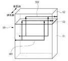
図2はW/J501、502を示す図である。図3はW/J501、502の冷却領域R1、R2を示す図である。図4は冷却領域R1、R2の拡大図である。図2はエンジン50の斜視図でW/J501、502の概略構造を示す。図3はエンジン50の上面図で冷却領域R1、R2を示す。図4は図3に示す冷却領域R1、R2のうち、エンジン50の一気筒当たりの冷却領域R1、R2を拡大して示す。冷却領域R1はシリンダヘッド52における第1のW/J501の冷却領域、冷却領域R2はシリンダヘッド52における第2のW/J502の冷却領域を示す。
FIG. 2 is a diagram showing W /
エンジン50はシリンダブロック51と、シリンダヘッド52と、ガスケット53と、点火プラグ54とを備えている。シリンダブロック51にはシリンダ51aが形成されている。シリンダブロック51には、ガスケット53を介してシリンダヘッド52が設けられている。ガスケット53は高い断熱性を有している。シリンダヘッド52には、シリンダ51a毎に点火プラグ54が設けられている。シリンダブロック51とシリンダヘッド52とは図示しないピストンとともに燃焼室を形成している。
The
第1のW/J501は、シリンダブロック51のうち、排気側の部分に冷却水を流通させるとともに、シリンダヘッド52のうち、点火プラグ54周辺の所定の領域を含め、排気側の部分に冷却媒体を流通させる。所定の領域は、シリンダヘッド52のうち、点火プラグ54周辺の部分を冷却可能な領域である。このため、シリンダヘッド52のうち、点火プラグ54周辺の部分は冷却領域R1に含まれている。
The first W /
第2のW/J502は、シリンダブロック51のうち、吸気側の部分に冷却水を流通させるとともに、シリンダヘッド52のうち、吸気側の部分に冷却水を流通させる。
The second W /
W/J501、502それぞれは、シリンダブロック51から冷却水を流入させるとともに、シリンダヘッド52から冷却水を流出させる縦流しの構造を有している。また、エンジン50の出力を取り出す側をリア側として、エンジン50のフロント側から冷却水を流入させるとともに、リア側から冷却水を流出させるようになっている。
Each of the W /
図1に示すように、冷却装置1Aでは複数の冷却水循環経路が形成されている。冷却水循環経路としては、例えば第1のW/J501が組み込まれた循環経路である第1の循環経路C1がある。第1の循環経路C1を流通する冷却水は、W/P11から吐出された後、第1のW/J501を流通し、さらにサーモスタット13を介するか、或いはラジエータ12およびサーモスタット13を介してW/P11に戻るようになっている。
As shown in FIG. 1, a plurality of cooling water circulation paths are formed in the
ラジエータ12は熱交換器であり、流通する冷却水と空気との間で熱交換を行うことで冷却水を冷却する。サーモスタット13はW/P11に入口側から連通する流通経路を切り替える。具体的にはサーモスタット13は、冷却水温が所定値未満の場合にラジエータ12をバイパスする流通経路を連通状態にし、所定値以上の場合にラジエータ12を流通する流通する流通経路を連通状態にする。
The
また冷却水循環経路としては、例えば第2のW/J502が組み込まれた循環経路である第2の循環経路C2がある。第2の循環経路C2を流通する冷却水は、W/P11から吐出された後、流量調節弁14を流通し、さらにサーモスタット13を介するか、或いはラジエータ12およびサーモスタット13を介してW/P11に戻るようになっている。
Further, as the cooling water circulation path, for example, there is a second circulation path C2 which is a circulation path in which the second W /
流量調節弁14は、第2の循環経路C2のうち、循環経路C1、C2が分岐した後の部分、且つエンジン50よりも上流側の部分に設けられている。流量調節弁14は、第2のW/J502を流通する冷却水の流量を調節することで、第2のW/J502の冷却能力を調整可能な冷却能力調整手段となっている。
The flow
また、流量調節弁14は、第1のW/J501の冷却能力を抑制することなく、第2のW/J502の冷却能力を抑制可能な冷却能力調整手段となっている。具体的には例えばW/J501、502にともに冷却水を流通させる高回転高負荷時の第1のW/J501の冷却能力および第2のW/J502の冷却能力がある場合に、これらの冷却能力に対して第1のW/J501の冷却能力を抑制することなく、第2のW/J502の冷却能力を抑制可能な冷却能力調整手段となっている。
Further, the flow
さらに、流量調節弁14は、第2のW/J502の冷却能力を抑制するように、第2のW/J502を流通する冷却水の流量を調節した場合に、第1のW/J501の冷却能力を高めるように、第1のW/J501を流通する冷却水の流量を調節可能な冷却能力調整手段となっている。
Furthermore, the flow
冷却装置1Aでは、第1の循環経路C1を流通する冷却水が、W/P11によって圧送された後、一巡するまでの間に第2のW/J502を流通することがないようになっている。また、第2の循環経路C2を流通する冷却水が、W/P11によって圧送された後、一巡するまでの間に第1のW/J501を流通することがないようになっている。すなわち、冷却装置1Aでは第1のW/J501と第2のW/J502とが互いに異なる冷却媒体循環経路に組み込まれている。第1のW/J501は第1の冷却媒体通路に相当し、第2のW/J502は第2の冷却媒体通路に相当する。
In the cooling device 1 </ b> A, the cooling water flowing through the first circulation path C <b> 1 is not circulated through the second W /
図5はECU70の概略構成図である。冷却装置1Aは電子制御装置であるECU70をさらに備えている。ECU70はCPU71、ROM72、RAM73等からなるマイクロコンピュータと入出力回路75、76とを備えている。これらの構成は互いにバス74を介して接続されている。
FIG. 5 is a schematic configuration diagram of the
ECU70には、エンジン50の回転数を検出するためのクランク角センサ81や、吸入空気量を計測するためのエアフロメータ82や、アクセル開度を検出するためのアクセル開度センサ83や、冷却水の温度を検知する水温センサ84などの各種のセンサ・スイッチ類が電気的に接続されている。この点、エンジン50の負荷はエアフロメータ82やアクセル開度センサ83の出力に基づきECU70で検出される。ECU70には、W/P11や流量調節弁14などの各種の制御対象が電気的に接続されている。
The
ROM72はCPU71が実行する種々の処理が記述されたプログラムやマップデータなどを格納するための構成である。CPU71がROM72に格納されたプログラムに基づき、必要に応じてRAM73の一時記憶領域を利用しつつ処理を実行することで、ECU70では各種の制御手段や判定手段や検出手段や算出手段などが機能的に実現される。
The
例えばECU70では、W/P11と流量調節弁14とを制御する制御手段が機能的に実現される。制御手段は、エンジン50に冷却水を流通させる場合に、W/P11を駆動する制御を行う。そしてこれにより、エンジン50に冷却水を流通させる場合に、W/J501に冷却水を流通させる。エンジン50に冷却水を流通させる場合は、例えば機関運転中である。エンジン50に冷却水を流通させる場合は、例えば機関冷間始動後、所定時間が経過した場合であってもよい。
For example, in the
また、制御手段は、エンジン50に冷却水を流通させる場合に、第2のW/J502に冷却水を流通させるにあたり、エンジン50の負荷が低中負荷である場合に、高負荷である場合よりも流量調節弁14の開度を小さくする制御を行う。そしてこれにより、エンジン50の負荷が低中負荷である場合に、高負荷である場合よりも第2のW/J502に流通させる冷却水の流量を減少させる。
In addition, when the cooling water is circulated through the
制御手段はエンジン50の負荷が高負荷である場合、流量調節弁14を例えば全開にすることができる。また、エンジン50の負荷が低中負荷である場合、流量調節弁14を例えば全閉、或いは冷却水の沸騰を抑制可能な態様で開弁することができる。W/P11を駆動する制御を行うにあたり、制御手段は、例えばエンジン50の回転数が高くなるほど吐出量が多くなるように制御を行うことができる。冷却装置1Aでは、W/P11と流量調節弁14とECU70とが冷却媒体制御手段に相当している。
When the load of the
次にECU70の動作を図6に示すフローチャートを用いて説明する。ECU70は機関運転中であるか否かを判定する(ステップS1)。否定判定であれば。W/P11を停止する(ステップS7)。そして、本フローチャートを一旦終了する。一方、肯定判定であれば、ECU70はW/P11を駆動する(ステップS2)。これにより、エンジン50に冷却水を流通させる場合に、第1のW/J501に冷却水が常時流通する。
Next, the operation of the
続いてECU70はエンジン50の負荷を検出する(ステップS3)。そして、検出した負荷が高負荷であるか否かを判定する(ステップS4)。肯定判定であれば、ECU70は流量調節弁14を開弁する(ステップS5)。否定判定であれば、ECU70は閉弁することを含め、流量調節弁14を高負荷である場合よりも小さい開度で開弁する(ステップS6)。これにより、エンジン50の負荷が低中負荷である場合に、高負荷である場合よりも第2のW/J502に流通させる冷却水の流量が減少する。
Subsequently, the
次に冷却装置1Aの作用効果について説明する。図7はクランク角度に応じた燃焼室の熱伝達率および表面積割合を示す図である。図7に示すように、熱伝達率は圧縮行程上死点付近で高まることがわかる。そして表面積割合については、圧縮行程上死点付近でシリンダヘッド52とピストンの表面積割合が大きくなることがわかる。したがって冷却損失については、シリンダヘッド52の温度の影響力が大きいことがわかる。
Next, the effect of the
一方、ノッキングについては圧縮端温度に依存するところ、圧縮端温度に影響する吸気圧縮行程ではシリンダ51aの表面積割合が大きいことがわかる。したがってノッキングについてはシリンダ51aの温度の影響力が大きいことがわかる。また、ノッキングについては、燃焼室に流入する吸気が当たる関係上、シリンダ51aのうち、排気側の部分のほうが吸気側の部分よりも温度の影響力が大きくなる。
On the other hand, knocking depends on the compression end temperature, and it can be seen that the surface area ratio of the
これに対し、冷却装置1Aは第1のW/J501に冷却水を流通させることで、エンジン50の排気側の部分を冷却することができる。そしてこれにより、シリンダ51aの排気側の部分を冷却することができる。また、エンジン50の排気側の部分は排気の都合上、高温になり易い部分となっている。このため、冷却装置1Aは第1のW/J501に冷却水を流通させることで、ノッキングの発生を好適に抑制できる。また、同時に点火プラグ54周辺の部分を冷却することで、エンジン50の信頼性も確保できる。
On the other hand, 1 A of cooling devices can cool the part by the side of the exhaust of the
また、冷却装置1Aは第2のW/J502を流通する冷却水の流量を制限することで、エンジン50の吸気側の部分で冷却損失を低減できる。そしてこれにより、シリンダヘッド52の吸気側の部分で冷却損失を低減できる。さらに、冷却装置1Aはエンジン50の排気側に第1のW/J501を設けるとともに、エンジン50の吸気側に第2のW/J502を設けることで、比較的製造し易い簡便な縦流しの構造を有することができる。
In addition, the
このため、冷却装置1Aは上述した知見に基づき、簡便な縦流しの構造で熱伝達の状態を局部的に可変することができる。そしてこれにより、冷却損失の低減とノック性能とを両立させることで、熱効率を向上させることができる。
Therefore, the
具体的には、冷却装置1Aはエンジン50に冷却水を流通させる場合に、第1のW/J501に冷却水を常時流通させることで、ノッキングの発生を好適に抑制できる。そして、同時にエンジン50の信頼性も好適に確保できる。また、第2のW/J502に冷却水を流通させるにあたり、エンジン50の負荷が低中負荷である場合に、高負荷である場合よりも第2のW/J502に流通させる冷却水の流量を減少させることで、低中負荷時に冷却損失を低減できる。そしてこれにより、冷却損失の低減とノック性能とを好適に両立させることができる。
Specifically, when the
また冷却装置1Aでは、流量調節弁14が、第2のW/J502の冷却能力を抑制するように、第2のW/J502を流通する冷却水の流量を調節した場合に、第1のW/J501の冷却能力を高めるように、第1のW/J501を流通する冷却水の流量を調節する。このため、冷却装置1Aはこれによって吸気をより一層冷却できる。結果、ノッキングの発生をさらに好適に抑制できる。
Further, in the
図8は冷却装置1Bの概略構成図である。冷却装置1Bは冷却装置1Aと比較して、EGR装置21と第1の分岐部22とをさらに備えている。EGR装置21はエンジン50に対して排気還流を行う。換言すれば、エンジン50は排気還流が行われるエンジンとなっている。
FIG. 8 is a schematic configuration diagram of the
EGR装置21は、EGR配管211とEGR流量調節弁212とEGRクーラ213とを備えている。EGR配管211はエンジン50に排気を還流させる。EGR流量調節弁212はエンジン50に還流させる排気の流量を調節する。EGRクーラ213は、冷却水との熱交換によってエンジン50に還流させる排気を冷却する。EGRクーラ213は冷却器に相当する。
The EGR device 21 includes an EGR pipe 211, an EGR flow rate adjustment valve 212, and an EGR cooler 213. The EGR pipe 211 recirculates the exhaust gas to the
第1の分岐部22は第1のW/J501を流通する冷却水を分流し、EGRクーラ213に流通させる。第1のW/J501を流通する冷却水とは、第1の循環経路C1を流通する冷却水のことである。したがって、第1の循環経路C1のうち、循環経路C1、C2が分岐してから合流するまでの間の部分を流通する冷却水を分流することで、第1のW/J501を流通する冷却水を分流することができる。
The
この点、第1の分岐部22は具体的には、第1のW/J501を流通する冷却水を第1のW/J501よりも下流側で分流し、EGRクーラ213に流通させる。EGRクーラ213に流通させた冷却水は、第1の循環経路C1のうち、第1の分岐部22よりも下流側、且つ循環経路C1、C2の合流地点よりも上流側の部分で合流させることができる。
In this regard, specifically, the first branching
次に冷却装置1Bの作用効果について説明する。ここで、EGRクーラ213はエンジン50に高温の排気を還流させるにあたり、ノッキングの発生を抑制するために設けられている。ところが、仮にエンジン50の冷却損失を低減するのに合わせて、EGRクーラ213に流通させる冷却水の流量を低下させたり、EGRクーラ213への冷却水の流通を停止したりすると、還流させる排気の温度上昇や冷却水の沸騰が発生することが懸念される。
Next, the effect of the
これに対し、冷却装置1Bは第1のW/J501を流通する冷却水を分流し、EGRクーラ213に流通させる。このため、冷却装置1BはEGR装置21の使用を好適に可能にすることができる。そしてこれにより、さらに排気還流による燃費向上を図ることができる。また、第1のW/J501を流通する冷却水を第1のW/J501よりも下流側で分流させることで、第1のW/J501の冷却性能に影響が及ぶことも防止できる。
On the other hand, the
図9は冷却装置1Cの概略構成図である。冷却装置1Cは冷却装置1Aと比較して、ヒータコア31と第2の分岐部32とをさらに備えている。なお、同様の変更を例えば冷却装置1Bに対して行うこともできる。ヒータコア31は車両の暖房に用いられ、流通する冷却水との熱交換によって空気を加熱する。ヒータコア31は加熱器に相当する。
FIG. 9 is a schematic configuration diagram of the cooling device 1C. The cooling device 1C further includes a
第2の分岐部32は第1のW/J501を流通する冷却水を分流し、ヒータコア31に流通させる。具体的には、第1のW/J501を流通する冷却水を第1のW/J501よりも下流側で分流し、ヒータコア31に流通させる。ヒータコア31に流通させた冷却水は、第1の循環経路C1のうち、第2の分岐部32よりも下流側、且つ循環経路C1、C2の合流地点よりも上流側の部分で合流させることができる。
The
次に冷却装置1Cの作用効果について説明する。冷却装置1Cは、第1のW/J501を流通する冷却水を分流し、ヒータコア31に流通させる。このため、冷却装置1Cはエンジン50の冷却損失を低減するのに合わせて、車両の暖房性能が低下することを抑制できる。すなわち、暖房の使用を好適に可能にすることができる。また、第1のW/J501を流通する冷却水を第1のW/J501よりも下流側で分流させることで、受熱量が多い冷却水を暖房に利用できる。結果、暖房性能を好適に高めることもできる。
Next, the effect of the cooling device 1C will be described. The cooling device 1 </ b> C diverts the cooling water flowing through the first W /
以上、本発明の実施例について詳述したが、本発明はかかる特定の実施例に限定されるものではなく、特許請求の範囲に記載された本発明の要旨の範囲内において、種々の変形・変更が可能である。 Although the embodiments of the present invention have been described in detail above, the present invention is not limited to such specific embodiments, and various modifications and changes can be made within the scope of the gist of the present invention described in the claims. It can be changed.
冷却装置 1A、1B、1C
W/P 11
ラジエータ 12
サーモスタット 13
流量調節弁 14
EGR装置 21
EGRクーラ 213
第1の分岐部 22
ヒータコア 31
第2の分岐部 32
エンジン 50
第1のW/J 501
第2のW/J 502
シリンダブロック 51
シリンダヘッド 52
ガスケット 53
点火プラグ 54
ECU 70
W /
EGR device 21
EGR cooler 213
1st W /
Second W /
Claims (4)
前記第1の冷却媒体通路が、前記冷却媒体を前記シリンダブロックのうち、排気側の部分に流通させた後に、前記シリンダヘッドのうち、前記シリンダヘッドに設けられた点火プラグ周辺の所定の領域を含め、排気側の部分に流通させ、
前記第2の冷却媒体通路が、前記第1の冷却媒体通路が組み込まれる冷却媒体循環経路とは異なる冷却媒体循環経路に組み込まれ、前記冷却媒体を前記シリンダブロックのうち、吸気側の部分に流通させた後に、前記シリンダヘッドのうち、吸気側の部分に流通させるエンジンの冷却装置。A cylinder block and a cylinder head of an engine provided with a first cooling medium passage and a second cooling medium passage for circulating the cooling medium;
After the first cooling medium passage circulates the cooling medium to the exhaust side portion of the cylinder block, a predetermined area around the spark plug provided in the cylinder head of the cylinder head is formed. Including the exhaust side,
The second cooling medium passage is incorporated in a cooling medium circulation path different from the cooling medium circulation path in which the first cooling medium passage is incorporated, and the cooling medium is circulated to a portion of the cylinder block on the intake side. An engine cooling device that is circulated to a portion on the intake side of the cylinder head.
流通する前記冷却媒体との間の熱交換によって前記エンジンに還流させる排気を冷却可能な冷却器と、前記第1の冷却媒体通路を流通する前記冷却媒体を分流し、前記冷却器に流通させる第1の分岐部と、をさらに備える請求項2記載のエンジンの冷却装置。The engine is an engine in which exhaust gas recirculation is performed;
A cooler capable of cooling the exhaust gas recirculated to the engine by heat exchange with the circulating cooling medium, and a cooling medium flowing through the first cooling medium passage, and the first cooling medium flowing through the cooler. The engine cooling device according to claim 2, further comprising: 1 branch portion.
Applications Claiming Priority (1)
| Application Number | Priority Date | Filing Date | Title |
|---|---|---|---|
| PCT/JP2010/072416 WO2012081081A1 (en) | 2010-12-13 | 2010-12-13 | Engine cooling apparatus |
Publications (2)
| Publication Number | Publication Date |
|---|---|
| JPWO2012081081A1 JPWO2012081081A1 (en) | 2014-05-22 |
| JP5541371B2 true JP5541371B2 (en) | 2014-07-09 |
Family
ID=46244210
Family Applications (1)
| Application Number | Title | Priority Date | Filing Date |
|---|---|---|---|
| JP2012548562A Expired - Fee Related JP5541371B2 (en) | 2010-12-13 | 2010-12-13 | Engine cooling system |
Country Status (5)
| Country | Link |
|---|---|
| US (1) | US20130247848A1 (en) |
| EP (1) | EP2653687A4 (en) |
| JP (1) | JP5541371B2 (en) |
| CN (1) | CN103261616B (en) |
| WO (1) | WO2012081081A1 (en) |
Families Citing this family (7)
| Publication number | Priority date | Publication date | Assignee | Title |
|---|---|---|---|---|
| CN106662033B (en) * | 2014-06-30 | 2019-01-18 | 日产自动车株式会社 | Internal combustion engine |
| WO2016001987A1 (en) * | 2014-06-30 | 2016-01-07 | 日産自動車株式会社 | Internal combustion engine |
| JP6264325B2 (en) * | 2015-06-05 | 2018-01-24 | トヨタ自動車株式会社 | Control device for internal combustion engine |
| JP6225950B2 (en) * | 2015-06-23 | 2017-11-08 | トヨタ自動車株式会社 | Cooling device for internal combustion engine |
| JP6465315B2 (en) * | 2016-11-30 | 2019-02-06 | 株式会社Subaru | Multi-cylinder engine cooling system |
| JP6791089B2 (en) * | 2017-10-11 | 2020-11-25 | 株式会社豊田自動織機 | Cylinder head cooling device |
| CN107956569A (en) * | 2017-11-28 | 2018-04-24 | 东风商用车有限公司 | A kind of engine cool management system |
Citations (4)
| Publication number | Priority date | Publication date | Assignee | Title |
|---|---|---|---|---|
| JPS63147916A (en) * | 1986-12-12 | 1988-06-20 | Yamaha Motor Co Ltd | Water-cooled engine |
| JPH10103055A (en) * | 1996-09-30 | 1998-04-21 | Mazda Motor Corp | Engine cooler |
| JP2001164988A (en) * | 1999-12-07 | 2001-06-19 | Toyota Motor Corp | Cylinder head |
| JP2010169010A (en) * | 2009-01-23 | 2010-08-05 | Aisin Seiki Co Ltd | Cooling device for internal combustion engine |
Family Cites Families (17)
| Publication number | Priority date | Publication date | Assignee | Title |
|---|---|---|---|---|
| US2807245A (en) * | 1954-10-19 | 1957-09-24 | Gen Motors Corp | Water heated intake manifold and control system therefor |
| US4109617A (en) * | 1976-12-22 | 1978-08-29 | Ford Motor Company | Controlled flow cooling system for low weight reciprocating engine |
| JPH08177483A (en) | 1994-12-26 | 1996-07-09 | Nissan Motor Co Ltd | Cooling device of multi-cylinder engine |
| US5735238A (en) * | 1996-10-21 | 1998-04-07 | Ford Global Technologies, Inc. | Heat management system for internal combustion engines |
| KR100559848B1 (en) * | 2002-09-27 | 2006-03-10 | 현대자동차주식회사 | engine cooling system |
| DE10306695A1 (en) * | 2003-02-18 | 2004-09-16 | Daimlerchrysler Ag | Internal combustion engine with a coolant circuit |
| JP4100279B2 (en) * | 2003-07-16 | 2008-06-11 | 三菱自動車工業株式会社 | Cylinder head precooled engine |
| DE10332947A1 (en) * | 2003-07-19 | 2005-02-03 | Daimlerchrysler Ag | Internal combustion engine for a motor vehicle |
| JP4175389B2 (en) * | 2006-06-05 | 2008-11-05 | トヨタ自動車株式会社 | Engine cooling system |
| EP1947308B1 (en) * | 2007-01-17 | 2009-09-30 | Ford Global Technologies, LLC | Integrated motor cooling system |
| JP4372799B2 (en) * | 2007-02-19 | 2009-11-25 | トヨタ自動車株式会社 | Internal combustion engine control system |
| JP4998339B2 (en) | 2008-03-12 | 2012-08-15 | トヨタ自動車株式会社 | Cooling device for internal combustion engine |
| EP2309106B1 (en) * | 2009-07-30 | 2017-06-07 | Ford Global Technologies, LLC | Cooling system |
| EP2309114B1 (en) * | 2009-07-30 | 2012-09-12 | Ford Global Technologies, LLC | Cooling system |
| US8746187B2 (en) * | 2009-12-01 | 2014-06-10 | Toyota Jidosha Kabushiki Kaisha | Engine cooling device |
| DE102010002082B4 (en) * | 2010-02-18 | 2013-09-19 | Ford Global Technologies, Llc | Separately cooled exhaust manifold to maintain a no-flow strategy of the cylinder block coolant jacket |
| US8662054B2 (en) * | 2011-03-09 | 2014-03-04 | Toyota Jidosha Kabushiki Kaisha | Engine control device |
-
2010
- 2010-12-13 US US13/991,213 patent/US20130247848A1/en not_active Abandoned
- 2010-12-13 WO PCT/JP2010/072416 patent/WO2012081081A1/en active Application Filing
- 2010-12-13 EP EP10860673.2A patent/EP2653687A4/en not_active Withdrawn
- 2010-12-13 CN CN201080070660.7A patent/CN103261616B/en not_active Expired - Fee Related
- 2010-12-13 JP JP2012548562A patent/JP5541371B2/en not_active Expired - Fee Related
Patent Citations (4)
| Publication number | Priority date | Publication date | Assignee | Title |
|---|---|---|---|---|
| JPS63147916A (en) * | 1986-12-12 | 1988-06-20 | Yamaha Motor Co Ltd | Water-cooled engine |
| JPH10103055A (en) * | 1996-09-30 | 1998-04-21 | Mazda Motor Corp | Engine cooler |
| JP2001164988A (en) * | 1999-12-07 | 2001-06-19 | Toyota Motor Corp | Cylinder head |
| JP2010169010A (en) * | 2009-01-23 | 2010-08-05 | Aisin Seiki Co Ltd | Cooling device for internal combustion engine |
Also Published As
| Publication number | Publication date |
|---|---|
| EP2653687A1 (en) | 2013-10-23 |
| CN103261616B (en) | 2015-04-01 |
| EP2653687A4 (en) | 2014-11-05 |
| JPWO2012081081A1 (en) | 2014-05-22 |
| US20130247848A1 (en) | 2013-09-26 |
| WO2012081081A1 (en) | 2012-06-21 |
| CN103261616A (en) | 2013-08-21 |
Similar Documents
| Publication | Publication Date | Title |
|---|---|---|
| JP5541371B2 (en) | Engine cooling system | |
| CN106164460B (en) | The egr system of internal combustion engine | |
| JP5494672B2 (en) | Engine cooling system | |
| JP5282827B2 (en) | Engine cooling system | |
| RU2628682C2 (en) | Engine system for vehicle | |
| JP5288046B2 (en) | Control device for internal combustion engine | |
| JP6090138B2 (en) | Engine cooling system | |
| JP6064981B2 (en) | Control device for internal combustion engine | |
| JP2011047305A (en) | Internal combustion engine | |
| JP2014009617A (en) | Cooling device of internal combustion engine | |
| WO2011067830A1 (en) | Cooling device for engine | |
| JP6007128B2 (en) | Exhaust recirculation system cooling system | |
| JP2018105189A (en) | Control device of internal combustion engine | |
| JP5051306B2 (en) | Engine cooling system | |
| US9551270B2 (en) | Control device for coolant flow in an internal combustion engine | |
| JP5577788B2 (en) | Engine cooling system | |
| JP5994450B2 (en) | Control device for variable flow pump | |
| JP2011094537A (en) | Cooling device for engine | |
| WO2019138582A1 (en) | Cooling system and cooling system control method | |
| JP6641940B2 (en) | Air intake cooling system for internal combustion engine | |
| JP5299517B2 (en) | Engine cooling system | |
| JP5304573B2 (en) | Engine warm-up promotion system | |
| JP6443728B2 (en) | Engine exhaust heat recovery system | |
| JP2023009868A (en) | EGR device | |
| JP2015124672A (en) | Internal combustion engine |
Legal Events
| Date | Code | Title | Description |
|---|---|---|---|
| TRDD | Decision of grant or rejection written | ||
| A01 | Written decision to grant a patent or to grant a registration (utility model) |
Free format text: JAPANESE INTERMEDIATE CODE: A01 Effective date: 20140408 |
|
| A61 | First payment of annual fees (during grant procedure) |
Free format text: JAPANESE INTERMEDIATE CODE: A61 Effective date: 20140421 |
|
| LAPS | Cancellation because of no payment of annual fees |