JP5540001B2 - Multiple temperature measurement with modeling - Google Patents
Multiple temperature measurement with modeling Download PDFInfo
- Publication number
- JP5540001B2 JP5540001B2 JP2011532349A JP2011532349A JP5540001B2 JP 5540001 B2 JP5540001 B2 JP 5540001B2 JP 2011532349 A JP2011532349 A JP 2011532349A JP 2011532349 A JP2011532349 A JP 2011532349A JP 5540001 B2 JP5540001 B2 JP 5540001B2
- Authority
- JP
- Japan
- Prior art keywords
- temperature sensor
- temperature
- housing
- heat
- opening
- Prior art date
- Legal status (The legal status is an assumption and is not a legal conclusion. Google has not performed a legal analysis and makes no representation as to the accuracy of the status listed.)
- Expired - Fee Related
Links
Images


Classifications
-
- G—PHYSICS
- G01—MEASURING; TESTING
- G01K—MEASURING TEMPERATURE; MEASURING QUANTITY OF HEAT; THERMALLY-SENSITIVE ELEMENTS NOT OTHERWISE PROVIDED FOR
- G01K13/00—Thermometers specially adapted for specific purposes
-
- A—HUMAN NECESSITIES
- A61—MEDICAL OR VETERINARY SCIENCE; HYGIENE
- A61B—DIAGNOSIS; SURGERY; IDENTIFICATION
- A61B5/00—Measuring for diagnostic purposes; Identification of persons
- A61B5/145—Measuring characteristics of blood in vivo, e.g. gas concentration, pH value; Measuring characteristics of body fluids or tissues, e.g. interstitial fluid, cerebral tissue
- A61B5/14532—Measuring characteristics of blood in vivo, e.g. gas concentration, pH value; Measuring characteristics of body fluids or tissues, e.g. interstitial fluid, cerebral tissue for measuring glucose, e.g. by tissue impedance measurement
-
- G—PHYSICS
- G01—MEASURING; TESTING
- G01K—MEASURING TEMPERATURE; MEASURING QUANTITY OF HEAT; THERMALLY-SENSITIVE ELEMENTS NOT OTHERWISE PROVIDED FOR
- G01K7/00—Measuring temperature based on the use of electric or magnetic elements directly sensitive to heat ; Power supply therefor, e.g. using thermoelectric elements
- G01K7/42—Circuits effecting compensation of thermal inertia; Circuits for predicting the stationary value of a temperature
- G01K7/427—Temperature calculation based on spatial modeling, e.g. spatial inter- or extrapolation
-
- G—PHYSICS
- G01—MEASURING; TESTING
- G01N—INVESTIGATING OR ANALYSING MATERIALS BY DETERMINING THEIR CHEMICAL OR PHYSICAL PROPERTIES
- G01N27/00—Investigating or analysing materials by the use of electric, electrochemical, or magnetic means
- G01N27/26—Investigating or analysing materials by the use of electric, electrochemical, or magnetic means by investigating electrochemical variables; by using electrolysis or electrophoresis
- G01N27/28—Electrolytic cell components
- G01N27/30—Electrodes, e.g. test electrodes; Half-cells
- G01N27/327—Biochemical electrodes, e.g. electrical or mechanical details for in vitro measurements
- G01N27/3271—Amperometric enzyme electrodes for analytes in body fluids, e.g. glucose in blood
- G01N27/3274—Corrective measures, e.g. error detection, compensation for temperature or hematocrit, calibration
Landscapes
- Health & Medical Sciences (AREA)
- Life Sciences & Earth Sciences (AREA)
- Physics & Mathematics (AREA)
- General Physics & Mathematics (AREA)
- Hematology (AREA)
- Molecular Biology (AREA)
- Chemical & Material Sciences (AREA)
- Pathology (AREA)
- General Health & Medical Sciences (AREA)
- Heart & Thoracic Surgery (AREA)
- Emergency Medicine (AREA)
- Medical Informatics (AREA)
- Biomedical Technology (AREA)
- Surgery (AREA)
- Animal Behavior & Ethology (AREA)
- Engineering & Computer Science (AREA)
- Public Health (AREA)
- Veterinary Medicine (AREA)
- Optics & Photonics (AREA)
- Biophysics (AREA)
- Chemical Kinetics & Catalysis (AREA)
- Electrochemistry (AREA)
- Analytical Chemistry (AREA)
- Biochemistry (AREA)
- Immunology (AREA)
- Investigating Or Analyzing Materials Using Thermal Means (AREA)
Description
(関連出願の相互参照)
本出願は2008年10月21日出願の米国特許仮出願第61/106,994号に対する優先権を主張し、その全体が参照により本明細書に組み込まれる。
(Cross-reference of related applications)
This application claims priority to US Provisional Application No. 61 / 106,994, filed Oct. 21, 2008, which is incorporated herein by reference in its entirety.
(発明の分野)
本発明は、血糖測定器のような医療診断システムによる、検体濃度の検出に関する。
(Field of Invention)
The present invention relates to detection of an analyte concentration by a medical diagnostic system such as a blood glucose meter.
バイオセンシング機器は、血液サンプル中の様々な検体(例えば、グルコース及びコレステロール)の検出のために使用される。例えば、血糖測定器は、患者の血液中のグルコース濃度を測定するために使用される医療診断機器であり、血液サンプルを受容するためのウェル又は反応領域を有する、使い捨てのサンプルストリップを採用する場合がある。一部の測定器は、血液サンプルを通過し得る電気量を測定することによってグルコース濃度を判定するセンサアセンブリを含むが、一方で他の測定器は、サンプルから反射する光量を測定するセンサアセンブリを含む。次いで、測定器のコンピュータのマイクロプロセッサが、センサアセンブリからの、測定された電気又は光を使用して、グルコース濃度を算定し、このグルコース濃度を数字で表示する。 Biosensing devices are used for the detection of various analytes (eg, glucose and cholesterol) in blood samples. For example, a blood glucose meter is a medical diagnostic instrument used to measure glucose concentration in a patient's blood and employs a disposable sample strip with a well or reaction area for receiving a blood sample There is. Some instruments include a sensor assembly that determines the glucose concentration by measuring the amount of electricity that can pass through the blood sample, while others measure a sensor assembly that measures the amount of light reflected from the sample. Including. The microprocessor of the meter computer then calculates the glucose concentration using the measured electricity or light from the sensor assembly and displays this glucose concentration numerically.
血液中の化学物質の濃度を測定する、電気化学的方法の重要な制限は、検体の拡散、及び試薬の様々な活性成分についての、交絡変数の影響である。例えば、検体の指数は、サンプルウェル又は反応領域を取り囲む、周囲温度によって影響を受ける。いずれの電気化学的検知方法の場合でも、測定サイクル中、又は測定サイクルの合間の温度の過渡的変化は、バックグラウンド信号、反応定数、及び/又は拡散係数を変動させる可能性がある。したがって、経時的な温度変化を観察するために、温度センサを使用する場合がある。経時的な最大温度変化の限界値をデータ画面上で使用し、測定値を無効化することができる。絶対的な温度の限界基準もまた利用可能であり、最低温度、及び/又は最高温度の検出をデータ画面上で使用し、測定値を無効化することができる。グルコースセンサのマイクロプロセッサは、試験環境の温度が所定の限界値の範囲内にあるか否かについて判定し、精度に悪影響を及ぼす恐れがある場合には、ユーザによる試験の実行を禁止することができる。それゆえ、グルコース測定器のいずれの温度検知要素も、グルコース測定器内部で発生する熱によって(例えば、バックライト液晶ディスプレイによって)影響を受けないことが重要である。 An important limitation of the electrochemical method for measuring the concentration of chemicals in the blood is the diffusion of the analyte and the influence of confounding variables on the various active components of the reagent. For example, the analyte index is affected by the ambient temperature surrounding the sample well or reaction area. For any electrochemical sensing method, transient changes in temperature during or between measurement cycles can cause background signals, reaction constants, and / or diffusion coefficients to fluctuate. Therefore, a temperature sensor may be used to observe a change in temperature over time. The limit value of the maximum temperature change over time can be used on the data screen to invalidate the measured value. Absolute temperature limit criteria are also available, and minimum and / or maximum temperature detection can be used on the data screen to override measurements. The glucose sensor microprocessor determines whether the temperature of the test environment is within a predetermined range of limits and may prohibit the user from performing the test if there is a risk of adversely affecting accuracy. it can. Therefore, it is important that no temperature sensing element of the glucose meter is affected by heat generated within the glucose meter (eg, by a backlit liquid crystal display).
グルコース測定器の温度検知要素は、測定器を取り囲む周囲温度へのアクセスを有するべきである。バイオセンシングデバイスによって読み取られる生化学反応の温度感度を考慮して、サンプル中の検体濃度の評価の間は、温度センサによって得られる周囲温度の値が直接使用される。結果として、検知された周囲温度における比較的軽微な変化であっても、生化学的指数における変動を生じさせ、誤ったアウトプットをもたらし得る。バイオセンシングデバイスによって提供されるアウトプットは、とりわけ薬剤の投与に関する、患者の判断に影響を与えることを意図するため、誤った指数を避けることが非常に重要である。したがって、バイオセンシング機器は、不正確な、又は紛らわしい周囲温度指数から生じる誤ったアウトプットを避けるための手段を含むべきである。 The temperature sensing element of the glucose meter should have access to the ambient temperature surrounding the meter. In view of the temperature sensitivity of the biochemical reaction read by the biosensing device, the ambient temperature value obtained by the temperature sensor is directly used during the evaluation of the analyte concentration in the sample. As a result, even relatively minor changes in the detected ambient temperature can cause fluctuations in the biochemical index, resulting in false output. Since the output provided by the biosensing device is intended to affect the patient's judgment, especially regarding drug administration, it is very important to avoid false indexes. Therefore, biosensing equipment should include means to avoid false outputs resulting from inaccurate or confusing ambient temperature indices.
様々な従来技術の機器が、周囲温度についての情報を得るために、内部熱センサ又は外部熱センサを採用しているが(例えば、特許文献1、特許文献2を参照)、一方で他の機器は、反応領域の温度の制御を試み、更に他のデバイスは、ACアドミタンス測定値と組み合わせた周囲温度センサの使用に依存する、複雑なアルゴリズムを用いることにより、血液サンプル温度の間接的な測定値を得ることを試みている(特許文献3を参照)。
Various prior art devices employ internal or external thermal sensors to obtain information about ambient temperature (see, for example,
周囲温度を敏感に検知するセンサは、温度変化に迅速に反応し、それによって適時に情報を提供することが可能であるが、特定の状況下では、この属性が望ましくない結果を招く恐れがある。例えば、通常はユーザの手中に保持されるバイオセンシング機器が、テーブルの天板上に置かれると、急激な温度変化が発生する場合があり、周囲温度指数が安定するまでは、以降の生化学的指数を偏倚させる恐れがある。反応領域の温度の制御を試みる機器については、そのバイオセンシング機器がバッテリー駆動の場合、反応領域の温度の制御は、必要とされるこの機器のバッテリーからの電力ドレインが大きすぎるため、非実用的なものになる。更に、特許文献3に記載されるような特定の手法は、周囲温度の推定の問題に対して共通な解決方法を提供するものではなく、その特許に記載の手法は、特定のグルコースストリップとの使用のために設計されており、そのストリップの化学的特性、又はストリップの幾何学形状を変更した場合、開示されたアルゴリズムを修正しなければならない。これらの問題を克服し得る温度検知システム、また他の場合は、バイオセンシング機器による検体測定の精度を改善し得る温度検知システムが、今なお必要とされている。
Sensors that are sensitive to ambient temperature can react quickly to temperature changes and thereby provide information in a timely manner, but under certain circumstances this attribute can have undesirable consequences . For example, when a biosensing device that is normally held in the user's hand is placed on the top of the table, a sudden temperature change may occur. Until the ambient temperature index stabilizes, There is a risk of biasing the target index. For devices that attempt to control the temperature of the reaction zone, if the biosensing device is battery powered, controlling the temperature of the reaction zone is impractical because the required power drain from the device battery is too large. It will be something. Furthermore, the specific technique as described in
本発明の一態様では、内部スペースを実質的に画定するハウジングと、ハウジング内部にある、又はハウジングに近接する、検体測定構成要素と、ハウジング内部の第1位置に配置され、熱源と熱伝達する、第1温度センサと、ハウジング内部の第2位置に配置され、第1温度センサと比較して低い程度で、熱源と熱伝達する、第2温度センサと、ハウジング内部に配置され、第1温度センサ及び第2温度センサと電子通信して、温度センサからの温度データを使用し、検体測定構成要素に関連する温度を算出する、プロセッサと、を含む、システムが提供される。 In one aspect of the invention, a housing that substantially defines an interior space, an analyte measurement component that is within or near the housing, and a first location within the housing that is in heat transfer with a heat source. The first temperature sensor and the second temperature sensor disposed at the second position inside the housing and transferring heat with the heat source to a lower degree than the first temperature sensor, and disposed at the first temperature inside the housing. And a processor in electronic communication with the sensor and the second temperature sensor, using temperature data from the temperature sensor and calculating a temperature associated with the analyte measurement component.
内部スペースを実質的に画定するハウジングと、ハウジング内部にある、又はハウジングに近接する、検体測定構成要素と、ハウジング内部の第1位置に配置され、熱源と熱伝達する、第1温度センサと、ハウジング内部の第2位置に配置され、第1温度センサと比較して高い程度で、ハウジングの外側の周囲環境と熱伝達する第2温度センサと、ハウジング内部に配置され、第1温度センサ及び第2温度センサと電子通信して、温度センサからの温度データを使用し、検体測定構成要素に関連する温度を算出する、プロセッサと、を含む、システムもまた開示される。 A housing that substantially defines an interior space; an analyte measurement component that is within or proximate to the housing; and a first temperature sensor that is disposed in a first position within the housing and is in heat transfer with a heat source; A second temperature sensor disposed at a second position inside the housing and transferring heat to an ambient environment outside the housing to a higher degree than the first temperature sensor; A system is also disclosed that includes a processor that is in electronic communication with the two temperature sensors and uses temperature data from the temperature sensor to calculate a temperature associated with the analyte measurement component.
更に別の態様では、検体評価システム内に挿入される試験ストリップに関連する温度を算出するための方法であって、検体評価システム内の熱源と熱伝達する、第1位置における第1温度を測定することと、第1位置と比較して低い程度で、熱源と熱伝達する、検体評価システム内の第2位置における第2温度を測定することと、測定された第1温度及び測定された第2温度を使用して、試験ストリップに関連する温度を算出することと、を含む方法が提供される。 In yet another aspect, a method for calculating a temperature associated with a test strip inserted in an analyte evaluation system, the method measuring a first temperature at a first location in heat transfer with a heat source in the analyte evaluation system. Measuring a second temperature at a second position in the analyte evaluation system that is in heat transfer with the heat source to a lower extent than the first position, and measuring the first temperature and the measured first temperature. Using two temperatures to calculate a temperature associated with the test strip.
本発明は、本開示の一部を形成する、添付図面及び実施例に関連して解釈される以下の詳細な説明を参照することにより、より容易に理解することができる。本発明は、本明細書に記載する及び/又は示す特定の製品、方法、条件又はパラメータに限定されるものではなく、本明細書で使用される専門用語は実施例を用いて具体的な実施形態を記載する目的のためだけのものであり、請求した発明を制限することを意図するものではないことが理解されるべきである。 The present invention may be understood more readily by reference to the following detailed description, taken in conjunction with the accompanying drawings and examples, which form a part of this disclosure. The present invention is not limited to the particular products, methods, conditions, or parameters described and / or shown herein, and the terminology used herein is not limited to the specific implementation examples. It should be understood that the form is for purposes of description only and is not intended to limit the claimed invention.
バイオセンシング機器を取り囲む周囲温度を測定するための、1つ以上の温度センサ、例えば、サーミスタ、温度計、又は熱電対デバイスを使用することで、生体サンプル中の1つ以上の検体の測定精度を改善するために使用され得る情報を提供することができる。しかしながら、こうした方法は、バイオセンシング機器の1つ以上の構成要素から発生する熱が周囲温度の決定に与える影響を考慮に入れておらず、また実際に、意図的に無視する場合がある。バイオセンシング機器内部の、熱源と熱伝達する位置における温度測定値を、機器の外側の周囲環境に近似の温度の測定値に加えて取得することは、サンプルとストリップのセンサアセンブリとの間の反応に影響を及ぼす実際の温度条件を、その機器が補正することが可能になることにより、試験サンプル中の検体の正確な測定を実施する機器の能力を改善させ得ることが、現在見出されている。本開示の「二重温度」測定のプロセスは、検体濃度に関する正確な指数を提供するための、バイオセンシング機器の能力を改善し、これにより、薬剤、医師若しくは看護師との相談、又は他の処置選択肢に関する、適切かつ適時な判断に必要な医療情報を得るためのユーザの能力に、明白な効果をもたらす。更に、本発明は、デバイスの向きと、電力変動と、周囲温度及びバイオセンシング機器内部の熱源と熱伝達する位置における温度の双方を測定するのではなく、周囲温度の推定のためにのみセンサを使用するデバイスにおいて、温度指数を歪める恐れがある他の要因とに左右されない温度決定を可能にする。 Increase the measurement accuracy of one or more analytes in a biological sample by using one or more temperature sensors, such as a thermistor, thermometer, or thermocouple device, to measure the ambient temperature surrounding the biosensing device Information that can be used to improve can be provided. However, such methods do not take into account the effect of heat generated from one or more components of the biosensing device on the determination of ambient temperature, and may actually be deliberately ignored. Obtaining a temperature measurement inside the biosensing instrument at a location where it is in heat transfer with the heat source, in addition to a temperature measurement approximating the ambient environment outside the instrument, is the reaction between the sample and the strip sensor assembly. It has now been found that the instrument's ability to perform accurate measurements of analytes in a test sample can be improved by allowing the instrument to correct actual temperature conditions that affect Yes. The process of “dual temperature” measurement of the present disclosure improves the ability of the biosensing device to provide an accurate index on analyte concentration, thereby allowing consultation with drugs, physicians or nurses, or other It has a clear effect on the user's ability to obtain the medical information necessary for proper and timely judgment regarding treatment options. Furthermore, the present invention does not measure both the orientation of the device, power fluctuations, ambient temperature and the temperature at the heat transfer location within the biosensing device, but only for the estimation of the ambient temperature. Allows the device to be used to determine temperature independent of other factors that can distort the temperature index.
本発明の一態様では、内部スペースを実質的に画定するハウジングと、ハウジング内部にある、又はハウジングに近接する、検体測定構成要素と、ハウジング内部の第1位置に配置され、熱源と熱伝達する、第1温度センサと、ハウジング内部の第2位置に配置され、第1温度センサと比較して低い程度で、熱源と熱伝達する、第2温度センサと、ハウジング内部に配置され、第1温度センサ及び第2温度センサと電子通信して、温度センサからの温度データを使用し、検体測定構成要素に関連する温度を算出する、プロセッサと、を含むシステムが提供される。 In one aspect of the invention, a housing that substantially defines an interior space, an analyte measurement component that is within or near the housing, and a first location within the housing that is in heat transfer with a heat source. The first temperature sensor and the second temperature sensor disposed at the second position inside the housing and transferring heat with the heat source to a lower degree than the first temperature sensor, and disposed at the first temperature inside the housing. And a processor in electronic communication with the sensor and the second temperature sensor, using temperature data from the temperature sensor and calculating a temperature associated with the analyte measurement component.
内部スペースを実質的に画定するハウジングと、ハウジング内部にある、又はハウジングに近接する、検体測定構成要素と、ハウジング内部の第1位置に配置され、熱源と熱伝達する、第1温度センサと、ハウジング内部の第2位置に配置され、第1温度センサと比較して高い程度でハウジングの外側の周囲環境と熱伝達する第2温度センサと、ハウジング内部に配置され、第1温度センサ及び第2温度センサと電子通信して、温度センサからの温度データを使用し、検体測定構成要素に関連する温度を算出する、プロセッサと、を含むシステムもまた開示される。 A housing that substantially defines an interior space; an analyte measurement component that is within or proximate to the housing; and a first temperature sensor that is disposed in a first position within the housing and is in heat transfer with a heat source; A second temperature sensor disposed at a second position inside the housing and transferring heat to an ambient environment outside the housing to a higher degree than the first temperature sensor; and disposed within the housing, the first temperature sensor and the second temperature sensor A system is also disclosed that includes a processor in electronic communication with the temperature sensor and using temperature data from the temperature sensor to calculate a temperature associated with the analyte measurement component.
更に別の態様では、検体評価システム内に挿入される試験ストリップに関連する温度を算出するための方法であって、検体評価システム内の熱源と熱伝達する、第1位置における第1温度を測定することと、第1位置と比較して低い程度で、熱源と熱伝達する、検体評価システム内の第2位置における第2温度を測定することと、測定された第1温度及び測定された第2温度を使用して、試験ストリップに関連する温度を算出することと、を含む方法が提供される。 In yet another aspect, a method for calculating a temperature associated with a test strip inserted in an analyte evaluation system, the method measuring a first temperature at a first location in heat transfer with a heat source in the analyte evaluation system. Measuring a second temperature at a second position in the analyte evaluation system that is in heat transfer with the heat source to a lower extent than the first position, and measuring the first temperature and the measured first temperature. Using two temperatures to calculate a temperature associated with the test strip.
特に指定のない限り、特定の実施形態、機構、構成要素、又は機能の説明は、本発明の方法及び本発明のシステムの双方に適用される。例えば、「システム」への言及は、本発明の方法の「検体評価システム」、及び別個の請求項に記載の「システム」の双方に適用される。 Unless otherwise specified, descriptions of particular embodiments, mechanisms, components, or functions apply to both the method of the present invention and the system of the present invention. For example, reference to “system” applies to both “analyte evaluation system” of the method of the invention and to “system” in the separate claims.
本発明のシステムは、内部スペースを実質的に画定するハウジングを含む。このハウジングは、任意の好適な材料で作製することができ、ハウジング内部に不可欠な構成要素を収容可能な、任意の適切な形状を採用することができる。多くのバイオセンシング機器は、1つ以上の成形部品から組み立てられるプラスチックのシェルを含む、ハウジングを有する。例えば、ハウジングは、第1半部分及び第2半部分を含むシェルであってもよく、一方の半部分は、水平静止位置で(例えば、テーブル天板上で、デバイスの長軸がテーブル天板の表面に実質的に平行であるように―デバイスが長軸を有さない場合は、「水平」配向は、例えば、天板表面に接触するデバイスの反対面上で、ディスプレイ、ボタンなどのような対話型構成要素が上方を向くような、デバイスの使用時の静止位置を指してもよく、又は第2温度センサと熱源との間の想像線によって形成される軸線が、天板表面に実質的に平行な状態を指してもよい)デバイスの「上」部を形成し、他方の半部分は、デバイスの「下」部を形成し、これら2つの半部分は、一体型シェルを形成するための相互の確実な取り付けを可能にするように、また内部構成要素、部分的にハウジングの外部に存在し得る構成要素(例えば、スイッチ、インターフェイスボタン、ディスプレイ構成要素など)、ハウジングの組み立てに必要な機構(連結部品、又はネジ穴若しくはリベット穴など)、バッテリー(すなわち、ハウジングは、バッテリーポート及び/又はバッテリードアを含み得る)、通気口などを収容するように構成されている。ハウジングはまた、ハウジングの外側側部上のゴムグリップ部分のような、ユーザのバイオセンシング機器を把持する能力を高める、1つ以上のコーティングされた区域を特徴とすることもできる。検体測定システムのハウジングを形成するために適切に使用できる、寸法、形状、及び材料のパラメータは、当業者によって容易に理解されよう。 The system of the present invention includes a housing that substantially defines an interior space. The housing can be made of any suitable material and can adopt any suitable shape that can accommodate the essential components within the housing. Many biosensing devices have a housing that includes a plastic shell assembled from one or more molded parts. For example, the housing may be a shell that includes a first half and a second half, with one half in a horizontal rest position (eg, on the table top, the long axis of the device being the table top Is substantially parallel to the surface of the device—if the device does not have a major axis, the “horizontal” orientation can be, for example, a display, button, etc. on the opposite side of the device that contacts the top surface. May point to a stationary position when the device is in use, such that the active interactive component faces upwards, or the axis formed by the imaginary line between the second temperature sensor and the heat source is substantially on the top surface Form the "upper" part of the device, the other half forms the "lower" part of the device, and these two halves form an integral shell To allow mutual secure mounting for Also, internal components, components that may be partly outside the housing (eg, switches, interface buttons, display components, etc.), mechanisms required for assembly of the housing (connecting parts, screw holes, rivet holes, etc.) The battery (ie, the housing may include a battery port and / or a battery door), a vent, and the like. The housing may also feature one or more coated areas that enhance the user's ability to grip the biosensing device, such as a rubber grip portion on the outer side of the housing. Those skilled in the art will readily understand the dimensions, shapes, and material parameters that can be suitably used to form the housing of the analyte measurement system.
検体測定構成要素は、ハウジング内部又はハウジングに近接して配置される。換言すれば、検体測定構成要素は、部分的に、又は完全にハウジング内部にあってもよく、ハウジングに取り付けても、又は別の方法で装着してもよく、ハウジングによって少なくとも部分的に画定されてもよく、あるいはこれらのいずれの組み合わせであってもよい。検体測定構成要素は、試験ストリップを受容するための開口を含み得、試験ストリップ上の検体の測定が可能であり、すなわち、試験ストリップ上の生体サンプル内に存在する検体を測定することができ、これによって、システムの他の構成要素に伝達可能な、検体測定データを提供する。検体測定構成要素は、従来のバイオセンシング機器においても見受けられ、例えば、開口は、ハウジングの一方の末端部に配置され(実際には、開口を画定するように、ハウジングが成形され得る)、試験ストリップの挿入された末端部と接触して、生体サンプルを保持するストリップ末端部から試験ストリップの挿入された末端部へと伝わってきた電気信号を受信する電気的構成要素を含む。開口は、典型的には、試験ストリップと同じ幅を有し、ユーザによって試験ストリップが挿入される、溝又はスロットを含む。電気的構成要素は、マイクロプロセッサのようなハウジング内部の処理装置と連動し、この処理装置には、電気的構成要素によって、試験ストリップから受信した信号に対応する検体測定データが供給される。検体測定構成要素に関する様々な構成は、当業者によって容易に理解され、本発明の検体測定構成要素は、従来のバイオセンシング機器の検体測定構成要素と同様の方法で構成され得ることが理解されよう。 The analyte measurement component is located within or adjacent to the housing. In other words, the analyte measurement component may be partially or fully internal to the housing, attached to the housing, or otherwise attached, and is at least partially defined by the housing. Or any combination thereof. The analyte measurement component can include an opening for receiving the test strip, and can measure an analyte on the test strip, i.e., can measure an analyte present in a biological sample on the test strip; This provides analyte measurement data that can be communicated to other components of the system. Analyte measurement components are also found in conventional biosensing equipment, for example, an opening is located at one end of the housing (actually, the housing can be shaped to define the opening) and testing An electrical component that contacts the inserted end of the strip and receives an electrical signal transmitted from the end of the strip holding the biological sample to the inserted end of the test strip. The opening typically includes a groove or slot having the same width as the test strip and into which the test strip is inserted by the user. The electrical component is associated with a processing device within the housing, such as a microprocessor, which is supplied with analyte measurement data corresponding to the signal received from the test strip by the electrical component. Various configurations relating to the analyte measurement component will be readily understood by those skilled in the art, and it will be understood that the analyte measurement component of the present invention can be configured in a manner similar to the analyte measurement component of conventional biosensing devices. .
第1温度センサ及び第2温度センサのそれぞれは、静的温度条件及び/又は動的温度条件が検出可能な、任意のデバイスとすることができる。とりわけ、サーミスタ、温度計、又は熱電対デバイスを含む、様々な種類の温度センサのいずれもが使用できることは、当業者には容易に理解されよう。第1温度センサは、ハウジング内部の第1位置に配置され、熱源と熱伝達する。現代のバイオセンシング機器は、典型的には、コンパクトなデバイスであり、バックライトを備えた液晶ディスプレイ、データ処理用のプロセッサ、無線通信用の高周波構成要素、及び多くの他の電子的構成要素若しくはサブアセンブリが組み込まれる場合が多く、こうした構成要素は、電力を消費し、結果として熱放散をもたらす。内部で電力消散するコンパクトなデバイスの内部温度は、時に有意に、周囲温度を超えて上昇する場合があり、このことは、単一の内部サーミスタを使用する測定値が実際の周囲温度を表さない場合があることを意味し得る。その結果、このことは、試験ストリップのサンプルウェル又は反応領域から導き出される検体指数に影響を及ぼし得る。本発明によれば、第1温度センサは、「熱源」(すなわち、バイオセンシング機器の部分として含まれる、少なくとも1つの熱発生構成要素又はサブアセンブリ)と熱伝達し、熱源によって発生した熱の、検体測定構成要素に関連する温度の決定に対して与える影響を明らかにするために使用することができる。検体測定構成要素に関連する温度の算出における、第1温度センサ及び第2温度センサからの温度データの使用に関する情報を、以下に説明する。本明細書で使用するとき、2つの構成要素の間、又は構成要素と環境との間の「熱伝達」とは、好ましくは、構成要素を、他の構成要素又は環境に関連する熱条件に晒すことを指し、様々な度合いの熱伝達が、構成要素の間に、又は構成要素と特定の環境との間に存在し得るために、熱を放出する第1の構成要素、又は特定の温度条件を保有する環境に関して、第2の構成要素は、第3の構成要素よりも低い程度、若しくは高い程度で、第1の構成要素又は環境と熱伝達し得る。 Each of the first temperature sensor and the second temperature sensor can be any device capable of detecting static temperature conditions and / or dynamic temperature conditions. One skilled in the art will readily appreciate that any of a variety of types of temperature sensors can be used, including, among other things, thermistors, thermometers, or thermocouple devices. The first temperature sensor is disposed at a first position inside the housing and transfers heat with a heat source. Modern biosensing equipment is typically a compact device, a liquid crystal display with a backlight, a processor for data processing, high frequency components for wireless communication, and many other electronic components or Often subassemblies are incorporated, and these components consume power and result in heat dissipation. The internal temperature of compact devices that dissipate power internally can sometimes rise significantly above ambient temperature, which means that measurements using a single internal thermistor represent the actual ambient temperature. It can mean that there may not be. As a result, this can affect the analyte index derived from the sample well or reaction area of the test strip. In accordance with the present invention, the first temperature sensor is in heat transfer with a “heat source” (ie, at least one heat generating component or subassembly included as part of a biosensing device) and of the heat generated by the heat source. It can be used to determine the effect on the determination of the temperature associated with the analyte measurement component. Information regarding the use of temperature data from the first temperature sensor and the second temperature sensor in calculating the temperature associated with the analyte measurement component is described below. As used herein, “heat transfer” between two components, or between a component and the environment, preferably means that the component is subjected to thermal conditions associated with other components or the environment. A first component that releases heat, or a specific temperature, because various degrees of heat transfer can exist between components or between a component and a specific environment With respect to an environment having conditions, the second component may transfer heat to the first component or environment to a lesser or higher degree than the third component.
特に指定のない限り、第1温度センサは、2つ以上の別個の温度検知デバイスを含み得る。それゆえ、熱源と熱伝達する2つ以上の温度センサが存在し得る。複数の「第1」温度センサが存在する場合、それぞれが同一の熱源と熱伝達してもよく、それぞれが異なる熱源とそれぞれに熱伝達してもよく、又はいくつかが1つの熱源と熱伝達する一方で、1つ以上が別の熱源と熱伝達してもよい。したがって、複数の「第1」温度センサが存在する場合、1つ以上のセンサを、ハウジング内部の同一の位置に、又はその近辺に配置してもよく、あるいは、各「第1」温度センサを、それぞれハウジング内部の異なる位置に配置してもよい(「第1」温度センサが配置される各位置は、いずれの第2温度センサの場所とも異なることが好ましい)。 Unless otherwise specified, the first temperature sensor may include two or more separate temperature sensing devices. There can therefore be more than one temperature sensor in heat transfer with the heat source. When there are multiple “first” temperature sensors, each may transfer heat to the same heat source, each may transfer heat to a different heat source, or some may transfer heat to a single heat source. However, one or more may transfer heat with another heat source. Thus, where there are multiple “first” temperature sensors, one or more sensors may be located at or near the same location within the housing, or each “first” temperature sensor may be , Each may be located at a different location within the housing (each location where the “first” temperature sensor is located is preferably different from the location of any second temperature sensor).
断熱材料を、第1温度センサと熱源との間に介在させることができる。断熱材料は、第1温度センサと熱源との間の熱伝達抵抗を増大させる、任意の物質又は条件を含む。例えば、断熱材料は、ゴム、プラスチック、金属、発泡体(例えば、ポリウレタンフォーム、スタイロフォームなど)、又はその多くの種類が当業者によって容易に理解される、任意の他の好適な材料とすることができる。複数の「第1」温度センサが存在する場合、一部又は全ての「第1」温度センサと、所定の「第1」温度センサに物理的に最近接する熱源との間に、断熱材料を配置してもよい。 An insulating material can be interposed between the first temperature sensor and the heat source. The thermal insulation material includes any material or condition that increases the heat transfer resistance between the first temperature sensor and the heat source. For example, the thermal insulation material may be rubber, plastic, metal, foam (eg, polyurethane foam, styrofoam, etc.), or any other suitable material, many types of which are readily understood by those skilled in the art. it can. In the case where there are multiple “first” temperature sensors, an insulating material is placed between some or all of the “first” temperature sensors and a heat source that is physically closest to the given “first” temperature sensor. May be.
第2温度センサは、ハウジング内部の第2位置(second position with the housing)に配置され、第1温度センサと比較して低い程度で、熱源と熱伝達する。例えば、第2温度センサは、空間変位(すなわち、第2温度センサと熱源との距離が、第1温度センサと熱源との距離よりも大きい)、第2温度(second temperature)と熱源との間の、熱に対する1つ以上の物理的障壁の存在(又は、第1温度センサと熱源との間の熱障壁の数、若しくは有効性と比較して、より多くの、若しくはより有効性の高い、第2温度(second temperature)と熱源との間の熱障壁の存在)、又はこれらのいずれの組み合わせによって、より低い程度で、熱源と熱伝達し得る。「熱源」が、バイオセンシング機器の部分として含まれる2つ以上の熱発生構成要素又はサブアセンブリを含む場合、第2温度センサは、第1温度センサが、2つ以上の熱発生構成要素又はサブアセンブリから放出される熱の合計量に晒されることと比較して、より低い程度で、2つ以上の熱発生構成要素又はサブアセンブリから放出される熱の合計量と熱伝達する。 The second temperature sensor is disposed at a second position within the housing (second position with the housing), and transfers heat with the heat source to a lower degree than the first temperature sensor. For example, the second temperature sensor has a spatial displacement (that is, the distance between the second temperature sensor and the heat source is larger than the distance between the first temperature sensor and the heat source), and between the second temperature (second temperature) and the heat source. The presence of one or more physical barriers to heat (or more or more effective compared to the number or effectiveness of thermal barriers between the first temperature sensor and the heat source, To a lesser extent, heat may be transferred to the heat source by a second temperature (the presence of a thermal barrier between the second temperature and the heat source), or any combination thereof. Where the “heat source” includes two or more heat generation components or subassemblies included as part of a biosensing device, the second temperature sensor is the first temperature sensor is more than one heat generation component or subassembly. To a lesser extent, heat transfer with the total amount of heat released from two or more heat generating components or subassemblies compared to exposure to the total amount of heat released from the assembly.
本発明の他の実施形態では、第2温度センサは、ハウジング内部の第2位置に配置され、第1温度センサと比較して高い程度で、システムハウジングの外側の周囲環境と熱伝達する。こうした場合では、第2温度センサと周囲環境との間に、より少ない物理的熱障壁、より有効性の低い熱障壁、若しくはより小さい空間変位が存在し得るか、又は第2温度センサと比較して、第1温度センサと周囲環境との間に、より多くの物理的熱障壁、より有効性の高い熱障壁、より大きい空間変位、若しくはこれらのいずれの組み合わせが存在し得る。 In another embodiment of the present invention, the second temperature sensor is disposed at a second position inside the housing and transfers heat to the surrounding environment outside the system housing to a higher degree compared to the first temperature sensor. In such cases, there may be less physical thermal barrier, less effective thermal barrier, or smaller spatial displacement between the second temperature sensor and the surrounding environment, or compared to the second temperature sensor. Thus, there may be more physical thermal barriers, more effective thermal barriers, larger spatial displacements, or any combination thereof between the first temperature sensor and the surrounding environment.
特に指定のない限り、第2温度センサは、2つ以上の別個の温度検知デバイスを含み得る。それゆえ、第1温度センサと比較して低い程度で、熱源と熱伝達する、2つ以上の温度センサが存在し得る。複数の「第1」及び「第2」温度センサが存在する場合、所定の「第2」温度センサに関しては、そうしたセンサは、少なくとも1つの「第1」温度センサと比較して、低い程度で、熱源と熱伝達するべきであり、又は少なくとも1つの「第1」温度センサと比較して、高い程度でシステムハウジングの外側の周囲環境と熱伝達するべきである。 Unless otherwise specified, the second temperature sensor may include two or more separate temperature sensing devices. Thus, there may be more than one temperature sensor that transfers heat with the heat source to a lesser extent than the first temperature sensor. Where there are a plurality of “first” and “second” temperature sensors, for a given “second” temperature sensor, such a sensor is to a lesser extent than at least one “first” temperature sensor. Should be in heat transfer with a heat source or to a high degree with the ambient environment outside the system housing as compared to at least one “first” temperature sensor.
断熱材料を、第2温度センサと熱源との間に介在させることができる。断熱材料は、第2温度センサと熱源との間の熱伝達抵抗を増大させる、任意の物質又は条件を含む。例えば、断熱材料は、ゴム、プラスチック、金属、発泡体(例えば、ポリウレタンフォーム、スタイロフォームなど)、又はその多くの種類が当業者によって容易に理解される、任意の他の好適な材料とすることができる。こうした断熱材料は、第1温度センサと熱源との間に断熱材料を介在させることと同時に、存在させることができる。複数の「第2」温度センサが存在する場合、一部又は全ての「第2」温度センサと、所定の「第2」温度センサに物理的に最も近接する熱源との間に、断熱材料を配置してもよい。 An insulating material can be interposed between the second temperature sensor and the heat source. The insulating material includes any substance or condition that increases the heat transfer resistance between the second temperature sensor and the heat source. For example, the thermal insulation material may be rubber, plastic, metal, foam (eg, polyurethane foam, styrofoam, etc.), or any other suitable material, many types of which are readily understood by those skilled in the art. it can. Such a heat insulating material can be present at the same time as the heat insulating material is interposed between the first temperature sensor and the heat source. In the case where there are multiple “second” temperature sensors, an insulating material is placed between some or all of the “second” temperature sensors and the heat source physically closest to the given “second” temperature sensor. You may arrange.
他の実施形態では、断熱材料を、第1温度センサと第2温度センサとの間に介在させることができる。上述のように、断熱材料は、熱伝達抵抗(この場合は、第1温度センサと第2温度センサとの間)の増大に役立ち得る、任意の物質、又は条件を含む。こうした断熱材料は、第1温度センサと熱源との間、第2温度センサと第1温度センサとの間(between a second temperature sensor and a first temperature sensor)、又は双方に断熱材料を介在させることと同時に(すなわち、その同一の実施形態において)、存在させることができる。複数の「第1」及び/又は「第2」温度センサが存在する場合、1つのみの「第1」温度センサと1つのみの「第2」温度センサとの間、又は一部、若しくは全ての「第1」温度センサと「第2」温度センサとの間に、断熱材料を配置してもよい。 In other embodiments, a thermal insulation material can be interposed between the first temperature sensor and the second temperature sensor. As described above, the thermal insulation material includes any substance or condition that can help increase the heat transfer resistance (in this case, between the first temperature sensor and the second temperature sensor). Such a heat insulating material is interposed between the first temperature sensor and the heat source, between the second temperature sensor and the first temperature sensor (between a second temperature sensor and a first temperature sensor), or both. Can be present at the same time (ie in the same embodiment thereof). If there are multiple “first” and / or “second” temperature sensors, or only between one “first” temperature sensor and only one “second” temperature sensor, or Insulating material may be placed between all “first” temperature sensors and “second” temperature sensors.
第1温度センサと熱源との間に介在する断熱材料、第2温度センサと熱源との間に介在する断熱材料、及び第1温度センサと第2温度センサとの間に介在する断熱材料のいずれの組み合わせも、本発明に従って使用することができる。 Any one of a heat insulating material interposed between the first temperature sensor and the heat source, a heat insulating material interposed between the second temperature sensor and the heat source, and a heat insulating material interposed between the first temperature sensor and the second temperature sensor. Combinations of these can also be used in accordance with the present invention.
第1温度センサ及び第2温度センサによってそれぞれ実施される温度の読み取りは、同時に行なってもよく、又は互いに対して異なる時間で行なってもよい。第1温度センサと第2温度センサとの間の空間的変化、及び任意的な時間変化を使用して、検体測定構成要素、試験ストリップ、又は双方に関連する温度の算出の精度を高めることができる。 The temperature readings respectively performed by the first temperature sensor and the second temperature sensor may be performed simultaneously or at different times relative to each other. Spatial variation between the first temperature sensor and the second temperature sensor, and any temporal variation, can be used to increase the accuracy of the temperature calculation associated with the analyte measurement component, the test strip, or both. it can.
第1温度センサ及び第2温度センサは、プロセッサと電子通信し、このプロセッサは、ハウジング内部に配置され、温度センサからの温度データを使用して、検体測定構成要素に関連する温度を算出する。電子通信は、直接的又は間接的な電子通信を指し、これによってプロセッサは、第1温度センサ及び第2温度センサの一方又は双方から直接的に温度データを受信し得るか、あるいはプロセッサは、第1温度センサ及び第2温度センサの一方又は双方から温度データを受け取り、そうしたデータをプロッセサに転送する構成要素から、温度データを受信し得る。プロセッサはまた、検体測定構成要素から直接的又は間接的に検体測定データを受信することもでき、また温度センサからの温度データを使用してこの検体測定データを調整することもできる。温度データを使用して検体測定データを調整するプロセッサは、温度データ及び検体測定データをそれぞれ他のプロセッサ構成要素から受信する、中央演算処理装置とすることができる。 The first temperature sensor and the second temperature sensor are in electronic communication with a processor that is disposed within the housing and uses temperature data from the temperature sensor to calculate a temperature associated with the analyte measurement component. Electronic communication refers to direct or indirect electronic communication by which the processor may receive temperature data directly from one or both of the first temperature sensor and the second temperature sensor, or the processor Temperature data may be received from a component that receives temperature data from one or both of the first temperature sensor and the second temperature sensor and forwards the data to the processor. The processor can also receive the analyte measurement data directly or indirectly from the analyte measurement component and can adjust the analyte measurement data using temperature data from the temperature sensor. The processor that uses the temperature data to adjust the sample measurement data may be a central processing unit that receives the temperature data and the sample measurement data from other processor components, respectively.
第2温度センサは、ハウジングの外側の周囲環境の温度に実質的に一致する温度データを提供することが理想的である。この目的のために、本発明のシステムは、好ましくは、周囲環境に近似の温度条件に第2温度センサを晒すことを可能にする、いずれの構成も採用し得るが、同時に、実用的な目的のために(例えば、センサへの損傷を防ぐために)、第2温度センサは、ハウジング内部に配置される。 Ideally, the second temperature sensor provides temperature data that substantially matches the temperature of the surrounding environment outside the housing. For this purpose, the system of the present invention can preferably employ any configuration that allows the second temperature sensor to be exposed to temperature conditions approximating the ambient environment, while at the same time being a practical purpose. For this purpose (eg, to prevent damage to the sensor), the second temperature sensor is disposed within the housing.
一部の実施形態では、周囲空気(すなわち、ハウジングの外側の周囲環境からの空気、又はハウジングの外側の周囲環境と同じ温度を有する空気)が、第2温度センサに接触し、第2温度センサに近接する加熱空気を置換する。例えば、本発明のシステムは、ハウジング内の、第2温度センサに近接する場所における第1開口部と、ハウジング内の、第2の場所における第2開口部と、第1開口部と第2開口部との間に延在し、第2温度センサを収容する流路と、を含み得、開口部のそれぞれは、流路を、ハウジングの外側の周囲環境と流体連通させて配置する。2つの場所の間の「流体連通」とは、それらの間に空気が流れる機能を指す。同様に、本発明のシステムは、ハウジングの外側の周囲環境から、内部スペースの少なくとも一部分内への空気流を可能にする対流システムを含み得、この空気流は、第2温度センサに近接する加熱空気を置換する。本明細書で使用するとき、「加熱空気」とは、バイオセンシング機器のハウジングの外側の周囲環境の温度を超えて上昇した温度を有する空気を指し、この温度の上昇は、典型的には、バイオセンシング機器の1つ以上の構成要素による熱放散に起因する。対流システムは、ハウジング内部の2つの場所の間に温度差が作り出されることからもたらされ得る。例えば、ハウジング内部で放散される熱は、典型的には、ハウジング上部に伝達され、ハウジング下部は、適切な断熱材料を使用して、熱源から隔離することができる。ハウジング下部とハウジング上部との間の温度差が、空気流を作り出す。 In some embodiments, ambient air (ie, air from an ambient environment outside the housing, or air having the same temperature as the ambient environment outside the housing) contacts the second temperature sensor, and the second temperature sensor Replace the heated air in the vicinity. For example, the system of the present invention includes a first opening at a location in the housing near the second temperature sensor, a second opening at the second location in the housing, a first opening, and a second opening. And a flow path that houses the second temperature sensor, and each of the openings places the flow path in fluid communication with the surrounding environment outside the housing. “Fluid communication” between two locations refers to the ability of air to flow between them. Similarly, the system of the present invention may include a convection system that allows air flow from an ambient environment outside the housing into at least a portion of the interior space, the air flow being heated adjacent to the second temperature sensor. Replace air. As used herein, “heated air” refers to air having a temperature that exceeds the temperature of the surrounding environment outside the housing of the biosensing device, and this increase in temperature is typically Due to heat dissipation by one or more components of the biosensing device. A convection system can result from the creation of a temperature difference between two locations inside the housing. For example, heat dissipated inside the housing is typically transferred to the top of the housing, which can be isolated from the heat source using a suitable insulating material. The temperature difference between the lower part of the housing and the upper part of the housing creates an air flow.
図1Aは、本発明の実施形態の側面図を示し(ハウジング内側の構成要素が見えるように、ハウジングの手前側壁は省略されている)、周囲空気は、開口部を経てハウジングに入り、第2温度センサを超えて流れて、第2温度センサに近接する加熱空気を置換することにより、加熱空気は、ハウジング内の第2開口部から流れ出る。空気流(矢印)の経路は、バイオセンシング機器の内部で、その機器を平坦表面上で水平の静止位置に定置したとき、好ましくは実質的に垂直に配向される流路の輪郭に対応する。図1Aでは、上述したもののような断熱材料を使用して、第2温度センサと、ハウジングの他の部分に位置決めされた1つ以上の熱源(図示せず)との間の熱伝達抵抗を増大させ、また、金属のような伝導性材料を使用して、ハウジングの、第2温度センサに近接する部分よりも良好な熱伝導率を提供し、ハウジング内部に温度差を作り出すことにより、第2温度センサから離れる熱流を更に促進させる。 FIG. 1A shows a side view of an embodiment of the present invention (the front side wall of the housing is omitted so that components inside the housing can be seen), and ambient air enters the housing through the opening and second By flowing over the temperature sensor and replacing the heated air proximate to the second temperature sensor, the heated air flows out of the second opening in the housing. The path of the air flow (arrow) corresponds to the contour of the flow path, preferably oriented substantially vertically, when the device is placed in a horizontal rest position on a flat surface within the biosensing device. In FIG. 1A, an insulating material such as that described above is used to increase the heat transfer resistance between the second temperature sensor and one or more heat sources (not shown) positioned in other parts of the housing. And by using a conductive material such as metal to provide a better thermal conductivity than the portion of the housing proximate to the second temperature sensor, creating a temperature difference within the housing, the second Further promotes heat flow away from the temperature sensor.
他の実施形態では、1つ以上の熱源が、周囲空気によって置換される加熱空気を形成するための熱を発生させる。それゆえ、ハウジングの外側の周囲環境からの空気流と、その結果としての第2温度センサに近接する加熱空気の置換とを許容する、対流システムを形成可能にするために、1つ以上の熱源が加熱空気を発生させ得る。一部の実施形態では、加熱空気は、熱源に接触する伝達要素を介して、熱源から伝達される熱により、形成される。例えば、熱源(例えば、マイクロプロセッサ)からの、回路基板を介して伝達される熱が、加熱空気を形成し得る。上述のように、バイオセンシング機器に関連する熱源は、バックライトを備えた液晶ディスプレイ、データ処理用のプロセッサ、無線通信用の高周波構成要素、及び他の多くの電力消費する電子的構成要素若しくはサブアセンブリを含み得る。一部の実施形態では、ハウジングの外側の周囲環境からの周囲空気が通過する流路は、少なくとも部分的に、熱源と熱伝達し得る。図1Bは、熱源が取り付けられたプリント回路基板(PCB)を介して、流路が熱源(例えば、マイクロプロセッサ―図示せず)と熱伝達する実施形態を示し、PCBは、断熱材料によって流路から隔てられておらず、実際には、ハウジングの外側の周囲環境から流れる空気によって置換される加熱空気を発生させる。空気流(矢印)の経路は、バイオセンシング機器の内部で、その機器を平坦表面上で静止位置に定置したとき、好ましくは実質的に垂直に配向される流路の輪郭に対応する。図1Bに示す変種の構成により、伝導性材料の使用(例えば、図1Aにおけるような)が不必要になり得る。加えて、こうした実施形態によれば、ストリップが挿入される開口は、第2温度センサから置換される加熱空気が通過して流路から出る「第2開口部」として機能し得るため、別個の「第2開口部」を提供する必要がなくなる。 In other embodiments, one or more heat sources generate heat to form heated air that is replaced by ambient air. Therefore, one or more heat sources to enable the formation of a convection system that allows air flow from the ambient environment outside the housing and consequent displacement of heated air in proximity to the second temperature sensor. Can generate heated air. In some embodiments, the heated air is formed by heat transferred from the heat source via a transfer element that contacts the heat source. For example, heat transferred through a circuit board from a heat source (eg, a microprocessor) can form heated air. As mentioned above, the heat sources associated with biosensing equipment include liquid crystal displays with backlights, processors for data processing, high frequency components for wireless communication, and many other power consuming electronic components or sub-components. An assembly may be included. In some embodiments, the flow path through which ambient air from the ambient environment outside the housing passes may be at least partially in heat transfer with the heat source. FIG. 1B illustrates an embodiment in which the flow path is in heat transfer with a heat source (eg, a microprocessor—not shown) via a printed circuit board (PCB) to which the heat source is attached, where the PCB is In fact, it generates heated air that is displaced from the ambient environment outside the housing and is replaced by air flowing from the surrounding environment. The path of the air flow (arrow) corresponds to the contour of the flow path, preferably oriented substantially vertically, when the device is placed in a rest position on a flat surface within the biosensing device. The variant configuration shown in FIG. 1B may obviate the use of conductive material (eg, as in FIG. 1A). In addition, according to such an embodiment, the opening into which the strip is inserted can function as a “second opening” through which the heated air displaced from the second temperature sensor passes and exits the flow path. There is no need to provide a “second opening”.
本発明のシステムは、周囲環境に近似の温度条件に第2温度センサを晒すことが可能な、いずれの他の構成を採用してもよい。特定の実施形態では、本発明のシステムは、第2温度センサとハウジングの外側の周囲環境との間の熱伝達抵抗を低減するように構成することができる。他の実施形態では、本発明のシステムは、第2温度センサとハウジングの外側の周囲環境との間の有効接触表面積を増大させるように構成することができる。例えば、第2温度センサは、ハウジング内の開口部に近接して位置決めされてもよい。第2温度センサと周囲環境との間の「接触」は、直接的である必要はなく、低い熱抵抗性を有する構成要素によって媒介されてもよい。例えば、第2温度センサは、ハウジング内の開口部に近接して位置決めされて、熱伝導性材料は、第2温度センサとハウジング内の開口部との間に配置されてもよい。「熱伝導性材料」とは、ハウジングを実質的に形成する材料よりも低い熱伝達抵抗を提供する、任意の材料を指し、例えば、熱伝導性材料は、金属(アルミニウム、銅、スチール、銀、又は真鍮のような合金など)、プラスチック、ガラス、又は任意の他の好適な材料とすることができる。あるいは、熱伝導性材料は、ハウジングを実質的に形成する材料と同一の材料としてもよいが、より薄い断面積を有し、このため熱伝導性材料を横切る熱伝達抵抗は、ハウジングの部分を横切る熱伝達抵抗と比較して減少する。第2温度センサは、センサとハウジング内の開口部との間に配置される熱伝導性材料上に取り付けることができる。一部の実施形態では、「ヒートシンク」材料を、熱伝導性材料とセンサとの間に配置することができる。ヒートシンク材料は、ハウジングの外側の周囲環境と第2温度センサとの間の熱伝達経路を最小化するような、低い熱伝達抵抗を有する、任意の物質とすることができる。ヒートシンク材料は、例えばヒートシンク材料に連接する構成要素の不整面を補正することによって、熱界面の熱伝導率を増大させる、流体状又はペースト状の物質とすることができる。例としては、熱グリース、熱ペースト、及び当業者には容易に理解される他の材料が挙げられる。 The system of the present invention may employ any other configuration that allows the second temperature sensor to be exposed to temperature conditions that approximate the ambient environment. In certain embodiments, the system of the present invention can be configured to reduce heat transfer resistance between the second temperature sensor and the ambient environment outside the housing. In other embodiments, the system of the present invention can be configured to increase the effective contact surface area between the second temperature sensor and the ambient environment outside the housing. For example, the second temperature sensor may be positioned proximate to the opening in the housing. The “contact” between the second temperature sensor and the surrounding environment need not be direct, but may be mediated by components having low thermal resistance. For example, the second temperature sensor may be positioned proximate to the opening in the housing and the thermally conductive material may be disposed between the second temperature sensor and the opening in the housing. “Heat conductive material” refers to any material that provides a lower heat transfer resistance than the material that substantially forms the housing, for example, a heat conductive material is a metal (aluminum, copper, steel, silver, Or an alloy such as brass), plastic, glass, or any other suitable material. Alternatively, the thermally conductive material may be the same material that substantially forms the housing, but has a thinner cross-sectional area, so that the heat transfer resistance across the thermally conductive material causes the portion of the housing to Reduced compared to crossing heat transfer resistance. The second temperature sensor can be mounted on a thermally conductive material disposed between the sensor and the opening in the housing. In some embodiments, a “heat sink” material can be placed between the thermally conductive material and the sensor. The heat sink material can be any material having a low heat transfer resistance that minimizes the heat transfer path between the ambient environment outside the housing and the second temperature sensor. The heat sink material can be a fluid or paste-like substance that increases the thermal conductivity of the thermal interface, for example, by correcting irregular surfaces of components connected to the heat sink material. Examples include thermal grease, thermal paste, and other materials readily understood by those skilled in the art.
第2温度センサ、ハウジング内の開口部、及び熱伝導性材料は、ハウジングによって画定される内部スペースの残部から、少なくとも部分的に隔離されてもよい。第2温度センサ、ハウジング内の開口部、及び熱伝導性材料の隔離は、上述の断熱材料(すなわち、熱伝達抵抗を増大させる任意の材料)の使用によって達成される、熱的分離を含み得る。図2は、システムを平坦表面上で静止位置に定置した場合(すなわち、システムの長軸が平坦表面に実質的に平行であるように、またシステムが長軸を有さなかった場合は、「水平」配向は、第2温度センサと熱源との間の想像線によって形成される軸線が、その表面に実質的に平行な状態を指してもよい)に見られるような、本発明の実施形態の水平配向された側面図を示し、内部の構成要素が見えるように、ハウジング3の手前側壁は省略されている。この実施形態は、ハウジング3内の開口部1を含み、それを覆って、熱伝導性材料のプレート5が配置される。第2温度センサ7がプレート5上に取り付けられ、これらの構成要素は、内部スペースの他の部分M1、M2から少なくとも部分的に熱的分離させるために、断熱材料9、11の内部に取り囲まれる。プレート5は、ハウジング3の外側の周囲環境Aと第2温度センサ7との間の有効接触表面積を増大させ、その結果、周囲環境Aと第2温度センサ7との間の熱伝達抵抗を低下させる。
The second temperature sensor, the opening in the housing, and the thermally conductive material may be at least partially isolated from the remainder of the interior space defined by the housing. Isolation of the second temperature sensor, the opening in the housing, and the thermally conductive material may include thermal isolation, achieved by use of the above-described thermal insulation material (ie, any material that increases heat transfer resistance). . FIG. 2 shows that when the system is placed in a stationary position on a flat surface (ie, if the major axis of the system is substantially parallel to the flat surface, and if the system has no major axis, “ Embodiments of the present invention such that the “horizontal” orientation is seen in the axis formed by the imaginary line between the second temperature sensor and the heat source may be substantially parallel to its surface) The front side wall of the
システムの配向が変化する場合、例えば、システムが、第2温度センサ7を「上」にして(図2に示すような、「側方」にではなく)垂直に配向された場合、熱源S(実際の構成要素は図示せず)から放出される熱が、対流によって、システムが水平に配向される場合よりも大きな程度で第2温度センサ7に到達し、そのため第2温度センサ7によって実施される温度の読み取りに誤差を生じさせることもあり得る。システムの配向の変化の影響を最小限に抑えるために、断熱材料を含む、任意的な熱対流障壁13を使用して、M1(この中に第1温度センサ8及び第2温度センサ7の双方が位置決めされる)とM2(この中に熱源Sが配置される)との間の熱伝達抵抗を増大させることができる。実施例2で立証するように、システムの内部スペースの、熱源が位置決めされる部分と、システムの内部スペースの部分との間に熱対流障壁を含むことによって、例えば水平から垂直へ、又はその逆に、システムの配向が変化する際の、熱対流の影響を補正することができる。
If the orientation of the system changes, for example, if the system is oriented vertically with the second temperature sensor 7 "up" (as opposed to "side" as shown in FIG. 2), the heat source S ( The heat released from the actual components (not shown) reaches the second temperature sensor 7 to a greater extent by convection than if the system is oriented horizontally, and is therefore implemented by the second temperature sensor 7. This may cause an error in the temperature reading. In order to minimize the effects of changes in the orientation of the system, an optional
第1温度センサ及び第2温度センサは、プロセッサと電子通信し、このプロセッサは、ハウジング内部に配置され、温度センサからの温度データを使用し、検体測定構成要素に関連する温度を算出する。次いで、このシステムは、試験ストリップ上の検体の測定の間に、検体測定構成要素に関連する算出された温度を補正することができる。例えば、試験ストリップ上の検体の測定は、第1温度センサ及び第2温度センサから取得した温度データを明らかにするために調整することができる、検体測定データの取得をもたらし得る。検体測定構成要素に関連する温度の算出、検体測定データの受信、及び検体測定構成要素に関連する算出された温度のいずれの補正も、第1温度センサ、第2温度センサ、及び検体測定構成要素のいずれに電子通信する個別のプロセッサによって実施してもよく、又は、これらの機能のそれぞれを、単一の多機能プロセッサによって実施してもよい。本明細書で使用するとき、「電子通信」は、物理的手段(例えば、回路)によって媒介されてもよく、又は「無線」であってもよい。検体測定データを受信するプロセッサは、第1温度センサ及び第2温度センサから温度データを受信する同一のプロセッサであってもよい。あるいは、温度データを使用して検体測定データを調整するプロセッサは、温度データ及び検体測定データを、それぞれ他のプロセッサ構成要素から受信する、中央演算処理装置としてもよい。本発明のシステムの、プロセッサ及び他の構成要素に関する、様々な構成は、当業者の容易に理解するところであり、本発明に従って、いずれの好適な構成も使用することができる。 The first temperature sensor and the second temperature sensor are in electronic communication with a processor that is disposed within the housing and uses temperature data from the temperature sensor to calculate a temperature associated with the analyte measurement component. The system can then correct the calculated temperature associated with the analyte measurement component during the measurement of the analyte on the test strip. For example, measurement of an analyte on a test strip can result in acquisition of analyte measurement data that can be adjusted to account for temperature data acquired from a first temperature sensor and a second temperature sensor. The first temperature sensor, the second temperature sensor, and the sample measurement component are used to calculate the temperature related to the sample measurement component, receive the sample measurement data, and correct the calculated temperature related to the sample measurement component. Each of these functions may be performed by a single multi-function processor. As used herein, “electronic communication” may be mediated by physical means (eg, circuitry) or may be “wireless”. The processor that receives the sample measurement data may be the same processor that receives the temperature data from the first temperature sensor and the second temperature sensor. Alternatively, the processor that adjusts the sample measurement data using the temperature data may be a central processing unit that receives the temperature data and the sample measurement data from other processor components. Various configurations for the processor and other components of the system of the present invention will be readily apparent to those skilled in the art, and any suitable configuration may be used in accordance with the present invention.
検体測定構成要素、及び/若しくは試験ストリップに関連する温度の算出、並びに/又は検体の測定の間の、検体測定構成要素、及び/若しくは試験ストリップに関連する算出された温度の補正のための、本発明のシステムに従って行なわれる考察を、簡易化した定常状態の熱力学的モデルを使用して説明することができる。図3A及び図3Bは、それぞれ、簡易熱力学的モデル、及び定常状態の熱力学的電気等価回路を示し、以下の略語を使用する。 For the calculation of the temperature associated with the analyte measurement component and / or the test strip and / or the correction of the calculated temperature associated with the analyte measurement component and / or the test strip during the measurement of the analyte, Considerations made in accordance with the system of the present invention can be explained using a simplified steady state thermodynamic model. 3A and 3B show a simplified thermodynamic model and a steady state thermodynamic electrical equivalent circuit, respectively, and use the following abbreviations:

力学的モデルでは、ハウジング及び温度センサに関して、電気等価モデル(図3B)におけるコンデンサとしてモデル化することができる、熱容量が存在する。定常状態では、これらのコンデンサは、高インピーダンスであり、無視することができる。それゆえ、温度差(TS−TA)は、RSA及びRMSの関係に従って、温度差(TM−TA)から算出され、そのために以下の式が適用される。
Kは、等式(2)によって定義される、システムの熱力学的構造に応じて決まる定数である。実際には、この定数は、TM、TS、及びTAの一連の温度測定値により、等式(3)を使用して推定される。この定数を、システムで使用するソフトウェアにプログラムする。次に、等式(4)を使用し、周囲温度をTM、TS、及びKを使用して推定する。示されるように、Kが小さくなるにつれて、TSは、より良好に周囲温度を表す。 K is a constant that depends on the thermodynamic structure of the system, defined by equation (2). In practice, this constant is estimated using equation (3) with a series of temperature measurements of TM, TS, and TA. This constant is programmed into the software used in the system. Equation (4) is then used to estimate the ambient temperature using TM, TS, and K. As shown, TS represents ambient temperature better as K decreases.
本発明によれば、プロセッサは、式(I)
![]()
![]()
実施例1―対流システム
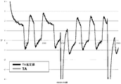
人工気候室を使用して、周囲環境からの空気に対する第2温度センサの曝露を増大させるための対流システムを提供するように設計された例示的なシステムを試験した。第2温度センサと、ハウジングによって画定されるシステムの内部スペースの残部との間の熱伝達抵抗を増大させるために、発泡ゴム断熱材料を使用して、第2温度センサを取り囲むチャンバを形成した。ハウジング内の開口部を使用して、周囲環境からチャンバ内への空気流を可能にし、また第2温度センサに近接する加熱空気の置換を可能にした。第1温度センサを回路基板上に位置決めし、ハウジング内側の内部スペースを、断熱材料によって2つの主要部分、すなわち、第1温度センサ、回路基板、及び第2温度センサを収容するチャンバが配置される、M1、並びに約1.4Wの電力消散を有する抵抗器を含む熱源が配置される、M2に分割した。実験の間、熱源をオン及びオフに切り替えて、バイオセンシング機器の通常動作中に生じるような熱放散変動周期の間の、システムの挙動をシミュレートした。温度指数を、5秒間隔で取得した。図4Aに結果を示し、ここでTSは第2温度センサによって取得された温度指数を表し、TMは第1温度センサによって取得された温度指数を表し、TS推定値(TS Estimation)は、第1温度センサ及び第2温度センサの指数を使用するシステムによって算出した周囲温度を表し、またTAは、試験室内で別個に測定した実際の周囲温度である。図4Bは、ハウジングの外側の周囲環境の温度(検体測定構成要素、試験ストリップ、又は双方に関連する温度に相当する)の算出における温度誤差を示す。結果を5秒間隔で示す。
Example 1-Convection System An exemplary system designed to provide a convection system to increase exposure of a second temperature sensor to air from the ambient environment using a climate chamber was tested. In order to increase the heat transfer resistance between the second temperature sensor and the rest of the internal space of the system defined by the housing, foam rubber insulation material was used to form a chamber surrounding the second temperature sensor. An opening in the housing was used to allow air flow from the ambient environment into the chamber and to allow replacement of heated air proximate to the second temperature sensor. A first temperature sensor is positioned on the circuit board, and an internal space inside the housing is disposed by a heat insulating material in two main parts: a first temperature sensor, a circuit board, and a chamber containing the second temperature sensor. , M1, and M2, where a heat source including a resistor with power dissipation of about 1.4W is placed. During the experiment, the heat source was switched on and off to simulate the behavior of the system during the heat dissipation fluctuation period as occurs during normal operation of the biosensing instrument. Temperature index was acquired at 5 second intervals. The results are shown in FIG. 4A, where TS represents the temperature index acquired by the second temperature sensor, TM represents the temperature index acquired by the first temperature sensor, and the TS estimate (TS Estimation) is the first It represents the ambient temperature calculated by the system using the index of the temperature sensor and the second temperature sensor, and TA is the actual ambient temperature measured separately in the test room. FIG. 4B shows the temperature error in the calculation of the temperature of the ambient environment outside the housing (corresponding to the temperature associated with the analyte measurement component, the test strip, or both). Results are shown at 5 second intervals.
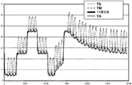
実施例2―周囲環境との有効接触表面積を増大させるシステム
人工気候室を使用して、第2温度センサと周囲環境との間の有効接触表面積が増大するように設計された例示的なシステムを試験した。この実験用システムは、開口部を有するハウジングを含み、この開口部を覆って、約0.5mmの厚さを有する真鍮プレートを定置した。第2温度センサを真鍮プレート上に取り付け、このセンサ/プレート配置物を、断熱材料によって画定されるチャンバ内部に取り囲んだ。チャンバを画定する断熱材料は、プラスチックのハウジング材料の層、すなわち、ハウジングの形成に使用されるものと同じ種類のプラスチックの層とした。約1.4Wの電力消散を提供する、外部供給電源を備えた抵抗器を、ハウジングによって画定される内部スペース内の、センサ/プレート配置物を取り囲むチャンバの外側に定置した。実験の間、熱源をオン及びオフに切り替えて、バイオセンシング機器の通常動作中に生じるような熱放散変動周期の間の、システムの挙動をシミュレートした。温度指数を5秒間隔で取得し、抵抗器が動作中の最長期間は、0.5時間とした。
Example 2-System for Increasing Effective Contact Surface Area with Ambient Environment An exemplary system designed to increase the effective contact surface area between a second temperature sensor and the ambient environment using a climate chamber Tested. The experimental system included a housing with an opening over which a brass plate having a thickness of about 0.5 mm was placed. A second temperature sensor was mounted on the brass plate and the sensor / plate arrangement was enclosed within a chamber defined by a thermally insulating material. The insulating material defining the chamber was a layer of plastic housing material, ie the same type of plastic layer used to form the housing. A resistor with an external power supply providing about 1.4 W of power dissipation was placed outside the chamber surrounding the sensor / plate arrangement within the internal space defined by the housing. During the experiment, the heat source was switched on and off to simulate the behavior of the system during the heat dissipation fluctuation period as occurs during normal operation of the biosensing instrument. The temperature index was acquired at 5 second intervals, and the longest period during which the resistor was operating was 0.5 hours.
図5Aに結果を示し、ここでTSは第2温度センサによって取得された温度指数を表し、TMは第1温度センサによって取得された温度指数を表し、TA推定値は、第1温度センサ及び第2温度センサの指数を使用するシステムによって算出した周囲温度を表し、またTAは、試験室内で別個に測定した実際の周囲温度である。 The results are shown in FIG. 5A, where TS represents the temperature index acquired by the second temperature sensor, TM represents the temperature index acquired by the first temperature sensor, and the TA estimate is the first temperature sensor and the first temperature sensor. It represents the ambient temperature calculated by the system using a two temperature sensor index, and TA is the actual ambient temperature measured separately in the test chamber.
図5Bは、ハウジングの外側の周囲環境の温度(検体測定構成要素、試験ストリップ、又は双方に関連する温度に相当する)の算出における温度誤差を示す。結果を5秒間隔で示す。 FIG. 5B shows the temperature error in the calculation of the temperature of the ambient environment outside the housing (corresponding to the temperature associated with the analyte measurement component, the test strip, or both). Results are shown at 5 second intervals.
上述のシステムに関する誤差の主要な原因としては、周囲温度の急変、システム内側の電力消散の変動、及び地面に対するシステムの配向が挙げられることが判明した。周囲温度が急激に変化した際に、大きな誤差のスパイクが認められたが、しかしながら、バイオセンシング機器の通常使用中は、周囲温度のそうした急激な変化に遭遇することは一般的ではない。それゆえ、温度誤差に関する関心領域は、システム内側の電力消散の変動及びシステムの配向の変化である。 It has been found that the major sources of errors associated with the systems described above include sudden changes in ambient temperature, fluctuations in power dissipation inside the system, and system orientation relative to the ground. A large error spike was observed when the ambient temperature changed rapidly, however, it is not common to encounter such a rapid change in ambient temperature during normal use of the biosensing device. Therefore, the areas of concern for temperature error are fluctuations in power dissipation inside the system and changes in system orientation.
図5A及び図5Bに示す測定は、システムが水平に配向されている間に、すなわち、平坦表面上で、デバイスの長軸をその表面に対し実質的に平行に配向して静止させて行なった。システムを垂直配向に移動した場合(すなわち、デバイスの長軸を表面に対し実質的に垂直に配向して―デバイスが長軸を有さない場合、「垂直」配向は、第2温度センサと熱源との間の想像線によって形成される軸線が、その表面に実質的に垂直な状態を指すことになる)、この簡易熱モデルは、第2温度センサを取り囲む空洞部に向かう熱対流に起因する、追加的な誤差を示した(結果は示さず)。システムが垂直に配向される場合の、熱対流の影響を低減するために、熱対流障壁をシステム内に組み込み(例えば、図2の物品13を参照)、一方は熱源を含み、他方はセンサ/プレート配置物を取り囲む空洞部を含む、2つの部分に、内部スペースを分割した。第1温度センサを、センサ/プレート配置物を取り囲む空洞部が位置する、ハウジング内部の同じスペース内に(すなわち、熱対流障壁の同じ側に)配置した。基板の一部分が熱対流障壁の一方の側にあり、基板の残り部分が熱対流障壁の反対の側にあるように配置したプリント回路基板(PCB)上に取り付けた、マイクロプロセッサの内側に、第1温度センサを配置した。熱源(抵抗器)を、熱対流障壁の第1温度センサとは反対の側にある、PCBの部分上に取り付けた。代替的な構成では、単一のPCBの代わりに、基板対基板コネクタによってリンクする2つの別個のPCBを含み得、ここで各PCBは、熱対流障壁の両側にある。熱対流障壁を備えるシステムを、水平配向及び垂直配向の双方において試験し、この障壁が、温度算出に対するシステムの配向の影響を、効果的に排除することを見出した。図6Aに結果を示し、ここで「H」表示のピーク値は、システムが水平配向にあった間に得られた温度指数に対応し、「V」表示のピーク値は、システムが垂直配向にあった間に得られた温度指数に対応し、TSは第2温度センサによって取得された温度指数を表し、TMは第1温度センサによって取得された温度指数を表し、TA推定値は、第1温度センサ及び第2温度センサの指数を使用するシステムによって算出した周囲温度を表し、またTAは、試験室内で別個に測定した実際の周囲温度である。
The measurements shown in FIGS. 5A and 5B were made while the system was oriented horizontally, ie, on a flat surface, with the long axis of the device oriented substantially parallel to the surface and stationary. . When the system is moved to a vertical orientation (ie, the major axis of the device is oriented substantially perpendicular to the surface—if the device does not have a major axis, the “vertical” orientation is the second temperature sensor and heat source This simple thermal model is due to thermal convection toward the cavity surrounding the second temperature sensor, with the axis formed by the imaginary line between them being substantially perpendicular to its surface) Showed additional errors (results not shown). In order to reduce the effects of thermal convection when the system is oriented vertically, a thermal convection barrier is incorporated into the system (see, eg,
図6Bは、ハウジングの外側の周囲環境の温度(検体測定構成要素、試験ストリップ、又は双方に関連する温度に相当する)の算出における温度誤差を示し、ここで「H」表示のピーク値は、システムが水平配向にあった間に得られた温度指数における誤差に対応し、「V」表示のピーク値は、システムが垂直配向にあった間に得られた温度指数における誤差に対応する。結果を5秒間隔で示す。 FIG. 6B shows the temperature error in the calculation of the ambient temperature outside the housing (corresponding to the temperature associated with the analyte measurement component, the test strip, or both), where the peak value labeled “H” is Corresponding to the error in the temperature index obtained while the system was in the horizontal orientation, the peak value on the “V” designation corresponds to the error in the temperature index obtained while the system was in the vertical orientation. Results are shown at 5 second intervals.
上記の実験は、とりわけ、検体測定プロセスに関連する温度の測定が、本発明の二重センサの手法を使用して改善されること、並びに、デバイスの配向及び電力消散の変動に関わりなく、正確な温度測定が実施できることを立証する。本発明の手法はまた、バイオセンシング機器を、それぞれ異なる周囲温度条件を特徴とする場所間で移動させた後に、ユーザがその機器の指数を使用するために待たなければならない時間量も低減する。こうした利点は、検体濃度に関する正確な指数を提供するための、バイオセンシング機器の能力を改善する。加えて、本明細書に記載のシステムは、コンパクトな設計を特徴とする現代の携帯用デバイスと関連した使用に適している。 The experiments described above are accurate, inter alia, that temperature measurements associated with the analyte measurement process are improved using the dual sensor approach of the present invention, and regardless of variations in device orientation and power dissipation. To prove that temperature measurements can be carried out. The inventive approach also reduces the amount of time that the user must wait to use the device index after moving the biosensing device between locations characterized by different ambient temperature conditions. These benefits improve the biosensing instrument's ability to provide an accurate index for analyte concentration. In addition, the system described herein is suitable for use in connection with modern portable devices featuring a compact design.
本明細書に引用、又は記載する各特許、特許出願、及び刊行物の開示は、その全文において本明細書に参考として組み込まれる。 The disclosures of each patent, patent application, and publication cited or described in this specification are hereby incorporated by reference in their entirety.
上記で使用のとき、また本開示全体を通して、以下の用語及び略語は、特に指示のない限り、以下の意味を有するものと理解されたい。本開示では、特に明示しない限り、単数形「a」、「an」、及び「the」は、複数形の言及を包含し、特定の数値への言及は、少なくともその特定の値を包含する。それゆえ、例えば「熱源」への言及は、1つ又はそれ以上の、そうした熱源、及び当業者には既知のその等価物への言及であり、その他の場合も同様である。値が、先行する「約」の使用によって近似値として表現されるとき、その特定の値は、別の実施形態を形成することが理解されよう。本明細書で使用するとき、「約X」(Xは数値である)は、好ましくは記載の値の±10%を包括的に指す。例えば、語句「約8」は、好ましくは7.2〜8.8の値を包括的に指し、別の例としては、語句「約8%」は、好ましくは7.2%〜8.8%の値を包括的に指す。存在する場合、全ての範囲は、包括的、分割可能、及び組み合わせ可能である。例えば「1〜5」の範囲が記載されるとき、記載の範囲は、「1〜4」、「1〜3」、「1〜2」、「1〜2及び4〜5」、「1〜3及び5」などの範囲を含むものとして解釈するべきである。 As used above and throughout the present disclosure, the following terms and abbreviations will be understood to have the following meanings unless otherwise indicated. In this disclosure, the singular forms “a”, “an”, and “the” include plural references and reference to a particular numerical value includes at least that particular value, unless expressly specified otherwise. Thus, for example, reference to “a heat source” is a reference to one or more such heat sources, and equivalents thereof known to those skilled in the art, and so on. It will be understood that when a value is expressed as an approximation by use of the preceding “about”, that particular value forms another embodiment. As used herein, “about X” (where X is a numerical value) preferably comprehensively refers to ± 10% of the stated value. For example, the phrase “about 8” preferably refers generically to a value of 7.2 to 8.8, and as another example, the phrase “about 8%” is preferably 7.2% to 8.8. Percentage value is comprehensively indicated. When present, all ranges are inclusive, separable, and combinable. For example, when ranges of “1-5” are described, the ranges described are “1-4”, “1-3”, “1-2”, “1-2 and 4-5”, “1-1-2”. It should be construed as including ranges such as “3 and 5”.
Claims (36)
前記ハウジング内部にある、又は前記ハウジングに近接する、少なくとも一つの熱発生構成要素又はサブアセンブリと、
前記ハウジング内部にある、又は前記ハウジングに近接する、検体測定構成要素と、
前記ハウジング内部の第1位置に配置され、前記少なくとも一つの熱発生構成要素又はサブアセンブリと熱伝達する、第1温度センサと、
前記ハウジング内部の第2位置に配置され、前記第1温度センサと比較して低い程度で、前記少なくとも一つの熱発生構成要素又はサブアセンブリと熱伝達する、第2温度センサと、
前記ハウジング内部に配置され、前記第1温度センサ及び前記第2温度センサと電子通信して、前記温度センサからの温度データを使用し、前記検体測定構成要素に関連する温度を算出する、プロセッサと、を含む、システム。 A housing that substantially defines an interior space;
At least one heat generating component or subassembly within or proximate to the housing;
An analyte measurement component within or proximate to the housing;
A first temperature sensor disposed in a first position within the housing and in heat transfer with the at least one heat generating component or subassembly ;
A second temperature sensor disposed in a second position within the housing and in heat transfer with the at least one heat generating component or subassembly to a lesser extent than the first temperature sensor;
A processor disposed within the housing and in electronic communication with the first temperature sensor and the second temperature sensor to use temperature data from the temperature sensor to calculate a temperature associated with the analyte measurement component; Including the system.
前記検体評価システム内の少なくとも一つの熱発生構成要素又はサブアセンブリと熱伝達する、第1位置における第1温度を測定することと、
前記第1位置と比較して低い程度で、前記少なくとも一つの熱発生構成要素又はサブアセンブリと熱伝達する、前記検体評価システム内の第2位置における第2温度を測定することと、
測定された前記第1温度及び測定された前記第2温度を使用して、前記試験ストリップに関連する温度を算出することと、を含む、方法。 A method for calculating a temperature associated with a test strip inserted in an analyte evaluation system comprising:
Measuring a first temperature at a first location in heat transfer with at least one heat generating component or subassembly in the analyte evaluation system;
Measuring a second temperature at a second position in the analyte evaluation system that is in heat transfer with the at least one heat generating component or subassembly to a lesser extent than the first position;
Calculating the temperature associated with the test strip using the measured first temperature and the measured second temperature.
前記ハウジング内部にある、又は前記ハウジングに近接する、少なくとも一つの熱発生構成要素又はサブアセンブリと、
前記ハウジング内部にある、又は前記ハウジングに近接する、検体測定構成要素と、
前記ハウジング内部の第1位置に配置され、前記少なくとも一つの熱発生構成要素又はサブアセンブリと熱伝達する、第1温度センサと、
前記ハウジング内部の第2位置に配置され、前記第1温度センサと比較して高い程度で、前記ハウジングの外側の周囲環境と熱伝達する、第2温度センサと、
前記ハウジング内部に配置され、前記第1温度センサ及び前記第2温度センサと電子通信して、前記温度センサからの温度データを使用し、前記検体測定構成要素に関連する温度を算出する、プロセッサと、を含む、システム。 A housing that substantially defines an interior space;
At least one heat generating component or subassembly within or proximate to the housing;
An analyte measurement component within or proximate to the housing;
A first temperature sensor disposed in a first position within the housing and in heat transfer with the at least one heat generating component or subassembly ;
A second temperature sensor disposed at a second position inside the housing and transferring heat to an ambient environment outside the housing to a higher degree than the first temperature sensor;
A processor disposed within the housing and in electronic communication with the first temperature sensor and the second temperature sensor to use temperature data from the temperature sensor to calculate a temperature associated with the analyte measurement component; Including the system.
Applications Claiming Priority (3)
| Application Number | Priority Date | Filing Date | Title |
|---|---|---|---|
| US10699408P | 2008-10-21 | 2008-10-21 | |
| US61/106,994 | 2008-10-21 | ||
| PCT/US2009/061492 WO2010048294A1 (en) | 2008-10-21 | 2009-10-21 | Multiple temperature measurements coupled with modeling |
Publications (2)
| Publication Number | Publication Date |
|---|---|
| JP2012506535A JP2012506535A (en) | 2012-03-15 |
| JP5540001B2 true JP5540001B2 (en) | 2014-07-02 |
Family
ID=42119656
Family Applications (1)
| Application Number | Title | Priority Date | Filing Date |
|---|---|---|---|
| JP2011532349A Expired - Fee Related JP5540001B2 (en) | 2008-10-21 | 2009-10-21 | Multiple temperature measurement with modeling |
Country Status (7)
| Country | Link |
|---|---|
| US (2) | US8313237B2 (en) |
| EP (1) | EP2350589B1 (en) |
| JP (1) | JP5540001B2 (en) |
| CN (1) | CN102575963B (en) |
| CA (1) | CA2740930A1 (en) |
| ES (1) | ES2719493T3 (en) |
| WO (1) | WO2010048294A1 (en) |
Families Citing this family (22)
| Publication number | Priority date | Publication date | Assignee | Title |
|---|---|---|---|---|
| WO2009119116A1 (en) * | 2008-03-27 | 2009-10-01 | パナソニック株式会社 | Environment temperature measuring method, liquid sample measuring method, and measuring device |
| EP2350589B1 (en) | 2008-10-21 | 2019-02-20 | Lifescan, Inc. | Analyte assessment system and method |
| US8473238B2 (en) * | 2010-08-11 | 2013-06-25 | Moog Inc. | Temperature measurement correction using multiple temperature sensors |
| US8801275B2 (en) | 2010-09-23 | 2014-08-12 | Bayer Healthcare Llc | System and apparatus for determining ambient temperatures for a fluid analyte system |
| EP2623972B1 (en) * | 2010-09-29 | 2020-11-18 | PHC Holdings Corporation | Device for measuring biological sample |
| US9823214B2 (en) * | 2011-11-01 | 2017-11-21 | Panasonic Healthcare Holdings Co., Ltd. | Biological sample measuring apparatus |
| US20130116526A1 (en) | 2011-11-09 | 2013-05-09 | Telcare, Inc. | Handheld Blood Glucose Monitoring Device with Messaging Capability |
| CN103868610B (en) * | 2012-12-17 | 2017-02-08 | 深圳合众思壮科技有限公司 | Temperature correction method, device and equipment |
| US9471117B1 (en) * | 2013-03-12 | 2016-10-18 | Google Inc. | Skin temperature of computing device enclosure |
| WO2014176379A2 (en) * | 2013-04-23 | 2014-10-30 | Canary Connect, Inc. | Security and/or monitoring devices and systems |
| US20140317857A1 (en) * | 2013-04-24 | 2014-10-30 | Whirlpool Corporation | Laundry treating appliances and methods of controlling the same to balance small loads |
| DE102014002762A1 (en) * | 2014-03-04 | 2015-09-10 | Storz Endoskop Produktions Gmbh | Measuring device and measuring method for detecting an ambient temperature of a device as well as device and method for medical insufflation |
| US9841391B2 (en) * | 2014-09-09 | 2017-12-12 | LifeSan Scotland Limited | Hand-held test meter with integrated thermal channel |
| CN104792439B (en) * | 2015-04-09 | 2018-07-24 | 杨松 | Thermometry, device, probe and system |
| JP6582769B2 (en) * | 2015-09-08 | 2019-10-02 | 株式会社デンソーウェーブ | Electronics |
| US10203249B2 (en) * | 2015-12-29 | 2019-02-12 | Google Llc | Ambient temperature sensing |
| KR101831066B1 (en) * | 2016-10-06 | 2018-02-22 | 경희대학교 산학협력단 | Temperature monitoring box using sensing array and method thereof |
| DE102017116505A1 (en) * | 2017-07-21 | 2019-01-24 | Endress+Hauser Conducta Gmbh+Co. Kg | Sensor of process automation technology and method for determining the temperature of a medium |
| WO2019143929A1 (en) * | 2018-01-18 | 2019-07-25 | In-Situ, Inc. | Fast response temperature sensors |
| CN110006554B (en) * | 2019-03-06 | 2022-06-14 | 深圳市锐同技术有限公司 | Thermometer calibration device and method |
| US11385665B2 (en) * | 2020-05-06 | 2022-07-12 | Computime Ltd. | Temperature compensation for an electronic thermostat |
| US11991820B2 (en) * | 2020-12-18 | 2024-05-21 | Comcast Cable Communications, Llc | Apparatus with airflow chamber |
Family Cites Families (19)
| Publication number | Priority date | Publication date | Assignee | Title |
|---|---|---|---|---|
| US4741476A (en) * | 1987-07-07 | 1988-05-03 | Honeywell Inc. | Digital electronic thermostat with correction for triac self heating |
| US5077476A (en) * | 1990-06-27 | 1991-12-31 | Futrex, Inc. | Instrument for non-invasive measurement of blood glucose |
| US5405511A (en) * | 1993-06-08 | 1995-04-11 | Boehringer Mannheim Corporation | Biosensing meter with ambient temperature estimation method and system |
| US5497772A (en) * | 1993-11-19 | 1996-03-12 | Alfred E. Mann Foundation For Scientific Research | Glucose monitoring system |
| JPH08201183A (en) * | 1995-01-31 | 1996-08-09 | Sony Corp | Temperature monitoring device |
| NZ504879A (en) * | 1997-12-04 | 2003-05-30 | Roche Diagnostics Corp | Instrument for engaging a power cell |
| US7407811B2 (en) * | 1997-12-22 | 2008-08-05 | Roche Diagnostics Operations, Inc. | System and method for analyte measurement using AC excitation |
| DE19952215C2 (en) * | 1999-10-29 | 2001-10-31 | Roche Diagnostics Gmbh | Test element analysis system |
| DE10032015A1 (en) * | 2000-07-01 | 2002-01-10 | Roche Diagnostics Gmbh | Test strip analysis unit for bodily fluid, employs temperature history correction system which will not drain batteries |
| GB2395561B (en) * | 2002-11-19 | 2006-03-08 | Qinetiq Ltd | Fluid temperature measurement |
| US20060229502A1 (en) * | 2003-06-03 | 2006-10-12 | Bayer Healthcare Llc | Portable medical diagnostic apparatus |
| US20050209813A1 (en) * | 2004-03-16 | 2005-09-22 | Johnson Controls Technology Company | Temperature sensing device |
| US7364353B2 (en) * | 2005-01-26 | 2008-04-29 | Carrier Corporation | Dynamic correction of sensed temperature |
| JP2007315917A (en) * | 2006-05-25 | 2007-12-06 | Terumo Corp | Apparatus for measuring deep temperature and external communication device |
| JP4805773B2 (en) * | 2006-09-20 | 2011-11-02 | シチズンホールディングス株式会社 | Electronic thermometer |
| JP5773241B2 (en) * | 2007-10-15 | 2015-09-02 | バイエル・ヘルスケア・エルエルシーBayer HealthCareLLC | Method and assembly for determining the temperature of a test sensor |
| EP2350589B1 (en) | 2008-10-21 | 2019-02-20 | Lifescan, Inc. | Analyte assessment system and method |
| WO2010151592A1 (en) * | 2009-06-23 | 2010-12-29 | Bayer Healthcare Llc | System and apparatus for determining temperatures in a fluid analyte system |
| US8801275B2 (en) * | 2010-09-23 | 2014-08-12 | Bayer Healthcare Llc | System and apparatus for determining ambient temperatures for a fluid analyte system |
-
2009
- 2009-10-21 EP EP09822632.7A patent/EP2350589B1/en not_active Not-in-force
- 2009-10-21 CA CA2740930A patent/CA2740930A1/en not_active Abandoned
- 2009-10-21 WO PCT/US2009/061492 patent/WO2010048294A1/en active Application Filing
- 2009-10-21 US US12/603,137 patent/US8313237B2/en active Active
- 2009-10-21 ES ES09822632T patent/ES2719493T3/en active Active
- 2009-10-21 CN CN200980142013.XA patent/CN102575963B/en not_active Expired - Fee Related
- 2009-10-21 JP JP2011532349A patent/JP5540001B2/en not_active Expired - Fee Related
-
2012
- 2012-10-16 US US13/652,629 patent/US8858072B2/en not_active Expired - Fee Related
Also Published As
| Publication number | Publication date |
|---|---|
| US8313237B2 (en) | 2012-11-20 |
| WO2010048294A1 (en) | 2010-04-29 |
| EP2350589A1 (en) | 2011-08-03 |
| US20130039383A1 (en) | 2013-02-14 |
| ES2719493T3 (en) | 2019-07-10 |
| US8858072B2 (en) | 2014-10-14 |
| JP2012506535A (en) | 2012-03-15 |
| CA2740930A1 (en) | 2010-04-29 |
| CN102575963A (en) | 2012-07-11 |
| US20100128754A1 (en) | 2010-05-27 |
| CN102575963B (en) | 2014-07-16 |
| EP2350589B1 (en) | 2019-02-20 |
| EP2350589A4 (en) | 2016-06-15 |
Similar Documents
| Publication | Publication Date | Title |
|---|---|---|
| JP5540001B2 (en) | Multiple temperature measurement with modeling | |
| US11015984B2 (en) | System and apparatus for determining ambient temperatures for a fluid analyte system | |
| US6787109B2 (en) | Test element analysis system | |
| CN102203574B (en) | Infrared temperature measurement of strip | |
| KR20060031804A (en) | Portable medical diagnostic apparatus | |
| US20060072645A1 (en) | Thermometry probe calibration method | |
| KR20240016453A (en) | Apparatus, systems, and methods for non-invasive thermal interrogation | |
| US8500327B2 (en) | Safety thermometer | |
| WO2013045897A1 (en) | Estimating ambient temperature from internal temperature sensor, in particular for blood glucose measurement | |
| KR101167614B1 (en) | Apparatus and method for measuring blood flow | |
| Cohen et al. | Comparison of closed chamber and open chamber evaporimetry | |
| RU2705395C2 (en) | Portable test and measurement device with integrated thermal channel | |
| Imhof et al. | TEWL, closed-chamber methods: AquaFlux and VapoMeter | |
| CN111595465A (en) | Active fixed-distance non-contact high-precision medical thermometer and temperature measuring method thereof | |
| TWM310332U (en) | Standard temperature calibration device for ear thermometer | |
| CN112763539B (en) | Detection device and detection method for liquid in metal container | |
| JP6892872B2 (en) | Test element analysis system for sample analysis and inspection |
Legal Events
| Date | Code | Title | Description |
|---|---|---|---|
| A621 | Written request for application examination |
Free format text: JAPANESE INTERMEDIATE CODE: A621 Effective date: 20120720 |
|
| A977 | Report on retrieval |
Free format text: JAPANESE INTERMEDIATE CODE: A971007 Effective date: 20130624 |
|
| A131 | Notification of reasons for refusal |
Free format text: JAPANESE INTERMEDIATE CODE: A131 Effective date: 20130702 |
|
| A521 | Request for written amendment filed |
Free format text: JAPANESE INTERMEDIATE CODE: A523 Effective date: 20130925 |
|
| TRDD | Decision of grant or rejection written | ||
| A01 | Written decision to grant a patent or to grant a registration (utility model) |
Free format text: JAPANESE INTERMEDIATE CODE: A01 Effective date: 20140408 |
|
| R150 | Certificate of patent or registration of utility model |
Ref document number: 5540001 Country of ref document: JP Free format text: JAPANESE INTERMEDIATE CODE: R150 |
|
| A61 | First payment of annual fees (during grant procedure) |
Free format text: JAPANESE INTERMEDIATE CODE: A61 Effective date: 20140501 |
|
| R250 | Receipt of annual fees |
Free format text: JAPANESE INTERMEDIATE CODE: R250 |
|
| R250 | Receipt of annual fees |
Free format text: JAPANESE INTERMEDIATE CODE: R250 |
|
| R250 | Receipt of annual fees |
Free format text: JAPANESE INTERMEDIATE CODE: R250 |
|
| R250 | Receipt of annual fees |
Free format text: JAPANESE INTERMEDIATE CODE: R250 |
|
| R250 | Receipt of annual fees |
Free format text: JAPANESE INTERMEDIATE CODE: R250 |
|
| LAPS | Cancellation because of no payment of annual fees |