JP5539620B2 - Method and apparatus for tracking an object - Google Patents
Method and apparatus for tracking an object Download PDFInfo
- Publication number
- JP5539620B2 JP5539620B2 JP2007547637A JP2007547637A JP5539620B2 JP 5539620 B2 JP5539620 B2 JP 5539620B2 JP 2007547637 A JP2007547637 A JP 2007547637A JP 2007547637 A JP2007547637 A JP 2007547637A JP 5539620 B2 JP5539620 B2 JP 5539620B2
- Authority
- JP
- Japan
- Prior art keywords
- signal
- inverse matrix
- impulse
- impulse signal
- matrix
- Prior art date
- Legal status (The legal status is an assumption and is not a legal conclusion. Google has not performed a legal analysis and makes no representation as to the accuracy of the status listed.)
- Active
Links
- 238000000034 method Methods 0.000 title claims description 84
- 239000011159 matrix material Substances 0.000 claims description 97
- 230000004044 response Effects 0.000 claims description 50
- 239000013598 vector Substances 0.000 claims description 37
- 238000012545 processing Methods 0.000 claims description 15
- 230000005540 biological transmission Effects 0.000 claims description 14
- 238000010586 diagram Methods 0.000 claims description 12
- 238000005070 sampling Methods 0.000 claims description 8
- 238000002604 ultrasonography Methods 0.000 claims description 5
- 238000000354 decomposition reaction Methods 0.000 claims description 4
- 230000003252 repetitive effect Effects 0.000 claims description 4
- 238000006073 displacement reaction Methods 0.000 claims description 3
- 230000000670 limiting effect Effects 0.000 claims description 3
- 238000013507 mapping Methods 0.000 description 10
- 238000004364 calculation method Methods 0.000 description 8
- 230000000694 effects Effects 0.000 description 8
- 230000008901 benefit Effects 0.000 description 7
- 230000008859 change Effects 0.000 description 7
- 230000002829 reductive effect Effects 0.000 description 7
- 230000002123 temporal effect Effects 0.000 description 7
- 230000008569 process Effects 0.000 description 4
- 230000007613 environmental effect Effects 0.000 description 3
- 238000005259 measurement Methods 0.000 description 3
- 238000012544 monitoring process Methods 0.000 description 3
- 238000012935 Averaging Methods 0.000 description 2
- 238000003384 imaging method Methods 0.000 description 2
- 238000013488 ordinary least square regression Methods 0.000 description 2
- 241000282412 Homo Species 0.000 description 1
- 238000007476 Maximum Likelihood Methods 0.000 description 1
- 241001122767 Theaceae Species 0.000 description 1
- 238000007792 addition Methods 0.000 description 1
- 230000002411 adverse Effects 0.000 description 1
- 238000013459 approach Methods 0.000 description 1
- 239000002131 composite material Substances 0.000 description 1
- 230000001143 conditioned effect Effects 0.000 description 1
- 230000003750 conditioning effect Effects 0.000 description 1
- 238000010219 correlation analysis Methods 0.000 description 1
- 230000007423 decrease Effects 0.000 description 1
- 238000002059 diagnostic imaging Methods 0.000 description 1
- 238000002592 echocardiography Methods 0.000 description 1
- 238000009472 formulation Methods 0.000 description 1
- 230000006870 function Effects 0.000 description 1
- 238000010230 functional analysis Methods 0.000 description 1
- ZZUFCTLCJUWOSV-UHFFFAOYSA-N furosemide Chemical compound C1=C(Cl)C(S(=O)(=O)N)=CC(C(O)=O)=C1NCC1=CC=CO1 ZZUFCTLCJUWOSV-UHFFFAOYSA-N 0.000 description 1
- PCHJSUWPFVWCPO-UHFFFAOYSA-N gold Chemical group [Au] PCHJSUWPFVWCPO-UHFFFAOYSA-N 0.000 description 1
- 208000015181 infectious disease Diseases 0.000 description 1
- 230000005055 memory storage Effects 0.000 description 1
- 239000000203 mixture Substances 0.000 description 1
- 230000036961 partial effect Effects 0.000 description 1
- 230000009467 reduction Effects 0.000 description 1
- 239000013535 sea water Substances 0.000 description 1
- 230000008054 signal transmission Effects 0.000 description 1
- 238000001228 spectrum Methods 0.000 description 1
- 230000003068 static effect Effects 0.000 description 1
- 238000012876 topography Methods 0.000 description 1
- 230000002087 whitening effect Effects 0.000 description 1
Images


Classifications
-
- G—PHYSICS
- G01—MEASURING; TESTING
- G01S—RADIO DIRECTION-FINDING; RADIO NAVIGATION; DETERMINING DISTANCE OR VELOCITY BY USE OF RADIO WAVES; LOCATING OR PRESENCE-DETECTING BY USE OF THE REFLECTION OR RERADIATION OF RADIO WAVES; ANALOGOUS ARRANGEMENTS USING OTHER WAVES
- G01S15/00—Systems using the reflection or reradiation of acoustic waves, e.g. sonar systems
- G01S15/02—Systems using the reflection or reradiation of acoustic waves, e.g. sonar systems using reflection of acoustic waves
- G01S15/06—Systems determining the position data of a target
-
- H—ELECTRICITY
- H04—ELECTRIC COMMUNICATION TECHNIQUE
- H04L—TRANSMISSION OF DIGITAL INFORMATION, e.g. TELEGRAPHIC COMMUNICATION
- H04L25/00—Baseband systems
- H04L25/02—Details ; arrangements for supplying electrical power along data transmission lines
- H04L25/0202—Channel estimation
- H04L25/0212—Channel estimation of impulse response
-
- H—ELECTRICITY
- H04—ELECTRIC COMMUNICATION TECHNIQUE
- H04L—TRANSMISSION OF DIGITAL INFORMATION, e.g. TELEGRAPHIC COMMUNICATION
- H04L25/00—Baseband systems
- H04L25/02—Details ; arrangements for supplying electrical power along data transmission lines
- H04L25/0202—Channel estimation
- H04L25/0224—Channel estimation using sounding signals
- H04L25/0226—Channel estimation using sounding signals sounding signals per se
-
- H—ELECTRICITY
- H04—ELECTRIC COMMUNICATION TECHNIQUE
- H04L—TRANSMISSION OF DIGITAL INFORMATION, e.g. TELEGRAPHIC COMMUNICATION
- H04L25/00—Baseband systems
- H04L25/02—Details ; arrangements for supplying electrical power along data transmission lines
- H04L25/0202—Channel estimation
- H04L25/024—Channel estimation channel estimation algorithms
- H04L25/0242—Channel estimation channel estimation algorithms using matrix methods
- H04L25/0244—Channel estimation channel estimation algorithms using matrix methods with inversion
-
- G—PHYSICS
- G01—MEASURING; TESTING
- G01S—RADIO DIRECTION-FINDING; RADIO NAVIGATION; DETERMINING DISTANCE OR VELOCITY BY USE OF RADIO WAVES; LOCATING OR PRESENCE-DETECTING BY USE OF THE REFLECTION OR RERADIATION OF RADIO WAVES; ANALOGOUS ARRANGEMENTS USING OTHER WAVES
- G01S15/00—Systems using the reflection or reradiation of acoustic waves, e.g. sonar systems
- G01S15/88—Sonar systems specially adapted for specific applications
- G01S15/89—Sonar systems specially adapted for specific applications for mapping or imaging
Description
本発明は、その環境又はその内部の1つ以上のオブジェクト(対象物)のマッピングを可能にする、インパルスに対するチャンネル応答を推定することに関し、特に音響インパルスを使用したものに関するが、それに限定するものではない。本発明は、特に、環境におけるリアルタイムの変化を測定することに関する。 The present invention relates to estimating a channel response to an impulse that allows mapping of one or more objects (objects) within or within the environment, and more particularly, but not exclusively, using acoustic impulses. is not. The invention particularly relates to measuring real-time changes in the environment.
環境に関する情報を得るために音響信号を使用し得ることが望ましいアプリケーションは、多種多様に存在する。例としては、人の追跡、人間とコンピュータとのインターフェース、海底マッピング、医療用超音波画像化診断、音響スキャナ、セキュリティ装置、及びロボットビジョンが含まれる。光ではなく音響信号を使用することには、例えば、光の状態に反応しないこと、人間が感知し得ない周波数で良く動作すること、向上された、又は簡単化された遠近感をもたらすことができること、といったいくつかの優位点をもつことが可能である。 There are a wide variety of applications where it is desirable to be able to use acoustic signals to obtain information about the environment. Examples include human tracking, human-computer interfaces, seabed mapping, medical ultrasound imaging diagnostics, acoustic scanners, security devices, and robot vision. Using acoustic signals rather than light can, for example, be unresponsive to light conditions, operate well at frequencies that humans cannot perceive, and provide improved or simplified perspective. It can have several advantages such as what it can do.
音響マッピングの基本原理は、短いバースト又はインパルスを環境内へ送信し、環境内における関心が持たれたオブジェクトからの反射を測定してそれに関する何か、通常はそのサイズ、形状又は位置を決定するというものである。これは、当該技術においては、チャンネルのインパルス応答の推定、又は単にチャンネル推定として知られている。音響モニタリングのためのチャンネル推定において遭遇する主たる障害は、望ましくないエコーによるものであり、これは事実上すべての現実的なアプリケーションにおいて発生する。チャンネル及び観察者の双方が静的であれば、これは重大な問題ではない。しかしながら、システムにおいて時間的に変換する何らかの要素が存在していれば、その変化を測定するためにインパルスを繰り返し送信する必要がある。送信されるパルスと先行パルスからのエコーとの間に干渉が存在する場合は、問題が生じる。図1a乃至図1dを参照して、この問題を説明する。 The basic principle of acoustic mapping is to send a short burst or impulse into the environment and measure the reflection from the object of interest in the environment to determine something about it, usually its size, shape or position That's it. This is known in the art as channel impulse response estimation, or simply channel estimation. The main obstacle encountered in channel estimation for acoustic monitoring is due to unwanted echo, which occurs in virtually all practical applications. This is not a serious problem if both the channel and the observer are static. However, if there is some element that converts in time in the system, it is necessary to repeatedly transmit impulses in order to measure the change. A problem arises if there is interference between the transmitted pulse and the echo from the preceding pulse. This problem will be described with reference to FIGS. 1a to 1d.
図1aは、所定の出力装置(例えば、ラウドスピーカ又はトランスデューサ)を介してインパルスが駆動され、結果的に生じる信号が所定の入力装置(例えば、マイクロホン、センサ)を介して受信される様子を示す。インパルス応答は時系列で示され、ここで、横軸は時間軸であり、縦軸は所定の時間における応答(例えば、圧力)を示す。推定されるインパルス応答は、チャンネルに関する重要な情報をもたらすことができ、従って、周囲環境、オブジェクト(「反射体」)の位置、変形及び形状に関する重要な情報をもたらすことができる。インパルス応答の推定は、無線通信から医療用画像化処理及び地震探査までに及ぶ、広範囲の信号処理アプリケーションの基礎である。 FIG. 1a shows how an impulse is driven via a predetermined output device (eg, a loudspeaker or transducer) and the resulting signal is received via a predetermined input device (eg, a microphone, sensor). . The impulse response is shown in time series, where the horizontal axis is a time axis, and the vertical axis shows a response (for example, pressure) at a predetermined time. The estimated impulse response can provide important information about the channel, and thus can provide important information about the surrounding environment, the position of the object ("reflector"), deformation and shape. Impulse response estimation is the basis for a wide range of signal processing applications, ranging from wireless communications to medical imaging and seismic exploration.
しかしながら、周囲環境が変化する可能性がある多数の状況が存在し、また、他の方法でもチャンネルは変化する。この変化は、モニタリング可能であることが望ましい。明らかに、最良の時間的分解能をもたらすためには、インパルス応答を可能な限り高頻度で測定する必要があるであろう。これを実行するための自明な方法は、図1(b)に示すようにインパルスをより高頻度で送信することであるようにも思われるが、これによって発生する問題がある。インパルスが先のインパルスのすぐ後で送信されると、図1(b)における主ピーク間の波状のパターンからわかるように、最初のインパルス応答からのエコーが次の推定に「影響を与える」。従って、チャンネルの推定のそれぞれは、その直前の推定によってある程度歪められる。これは、所望の信号をマスクするという点でノイズの一種ではあるが、信号強度を増大させたり、又は連続する推定値を平均化したりすることにより克服できるランダムな環境ノイズとは異なる。むしろこれは、これが信号自体から引き出されるものであって、当然ながら本来の目的であるチャンネルを完全に知ることなくしては訂正不可能であるという点で、「構造的」なノイズである。 However, there are a number of situations in which the surrounding environment can change, and the channel changes in other ways. This change should preferably be monitorable. Obviously, in order to provide the best temporal resolution, it will be necessary to measure the impulse response as frequently as possible. The obvious way to do this seems to be to send impulses more frequently as shown in FIG. 1 (b), but there are problems caused by this. If the impulse is transmitted immediately after the previous impulse, the echo from the first impulse response “influences” the next estimate, as can be seen from the wavy pattern between the main peaks in FIG. Thus, each channel estimate is distorted to some extent by the immediately preceding estimate. This is a type of noise in that it masks the desired signal, but it differs from random environmental noise that can be overcome by increasing signal strength or averaging successive estimates. Rather, it is a “structural” noise in that it is derived from the signal itself and, of course, cannot be corrected without fully knowing the channel for which it was originally intended.
この問題の深刻さは、図1(c)に示すように、出力インパルスがさらに高頻度で送信される場合に増大する。図1(c)の波形からの単一の「インパルス応答スライス」(図1(d)参照)を見て、これを、ただ1つのインパルスが送信された場合である図1(a)における対応する応答に比較すると、この例では、物理的なチャンネルに変化はなかったものの、測定による推定は大幅に異なるものであり、よって著しく不正確な結果をもたらすであろうという点で、チャンネルを高頻度で推定するという試みは失敗していることがわかる。 The severity of this problem increases when output impulses are transmitted more frequently, as shown in FIG. Looking at a single “impulse response slice” (see FIG. 1 (d)) from the waveform of FIG. 1 (c), this corresponds to that in FIG. 1 (a), where only one impulse is transmitted. In this example, although the physical channel did not change, the estimation by measurement was significantly different, and therefore the channel was increased in that it would lead to significantly inaccurate results. It can be seen that the attempt to estimate by frequency has failed.
上述の例は、チャンネル推定におけるジレンマを浮き彫りにするものである。チャンネルを正確に推定する(よって、例えば強い反射体の位置を発見する)ためには、「送信−受信−待機(send-receive-wait)」による方法を使用する必要がある。言いかえれば、送信信号を送り、戻り信号を受信し、そしてすべてのエコーが消滅するのを待ってから送信を繰り返すことが必要である。これにより、先のインパルスによる残存エコーから生じる構造的ノイズによって推定が損なわれることが回避される。しかしながら、これは、達成可能な時間的分解能を大幅に制限し、よって、多くのスキーム(海底マッピング装置、又は指の位置決め装置/コンピュータと人間とのインターフェース等)の時間的な追跡能力を大きく制限する。 The above example highlights the dilemma in channel estimation. In order to accurately estimate the channel (and thus find the position of a strong reflector, for example), it is necessary to use a “send-receive-wait” method. In other words, it is necessary to send a transmission signal, receive a return signal, and wait for all echoes to disappear before repeating the transmission. This avoids loss of estimation due to structural noise resulting from residual echo due to previous impulses. However, this greatly limits the achievable temporal resolution and thus greatly limits the temporal tracking capabilities of many schemes (such as a submarine mapping device, or finger positioning device / computer / human interface). To do.
必要とされているのは、チャンネルのインパルス応答の正確な推定値を連続的(continuously)に、又は継続的かつ頻繁(continually and frequently)に取得する方法、又はそれに代わって、インパルス応答をモニタリングするか又は追跡する方法である。 What is needed is a method of obtaining an accurate estimate of the channel impulse response continuously, continuously or frequently, or alternatively, monitoring the impulse response. Or how to track.
チャンネルの連続的な推定は、以前に、非特許文献1において提案されている。しかしながら、これらの方法は、いわゆる相互相関技術に基づくものである。その結果、これらには多大な欠点がある。特に、このような方法は、チャンネルのインパルス応答の推定値を継続的に更新するために送信信号及び受信信号のスライディングウィンドウとともに使用可能であるが、これらの技術の最適性能は、十分に長いウィンドウの使用に大きく依存するとともに、入力信号の完全な区分的直交性に依存することがわかる。言いかえれば、送信信号の各サンプルは他のサンプルのすべてに対して直交していなければならない。このことは、入力されるサンプル符号の各要素が1ウィンドウ分の長さだけ離れたその同じ符号の対応する要素と必ず直交するように、スライディングウィンドウ内において信号が単に増分的にシフトされるとみなされる場合には特に、達成が非常に困難である。相互相関に依存するスキームは、直交性要件を可能な限り十分に満足する系列(シーケンス)を発見するという上記のニーズによって左右される。このような符号におけるいくつかの試みの例は、カオス符号化、ゴールド系列、及びゴラン符号によって与えられる。しかしながら、これらのうちの何れも、満足のいく結果を出していない。
The continuous estimation of the channel has been previously proposed in
本発明の目的は、チャンネルのインパルス応答の推定、特にその変化の推定を向上させることにある。 An object of the present invention is to improve the estimation of the channel impulse response, in particular the estimation of its change.
本発明は、第1の態様を参照すると、チャンネルのインパルス応答の推定方法を提供し、上記方法は、インパルス信号を上記チャンネルへ送信することと、上記チャンネルから受信信号を検出することと、インパルス信号の計算された逆行列を受信信号へ適用して上記チャンネルのインパルス応答の推定値を計算することとを含む。 Referring to the first aspect, the present invention provides a method for estimating an impulse response of a channel, the method transmitting an impulse signal to the channel, detecting a received signal from the channel, and an impulse. Applying a calculated inverse matrix of the signal to the received signal to calculate an estimate of the impulse response of the channel.
本発明はさらに、チャンネル応答を推定する装置も包含し、本装置は、送信手段と受信手段と処理手段とを備え、上記処理手段は、上記送信手段により送信されたインパルス信号の計算された逆行列を、上記受信手段により受信された信号へ適用するように構成される。 The present invention further includes an apparatus for estimating a channel response, the apparatus comprising a transmitting means, a receiving means, and a processing means, wherein the processing means is a computed inverse of the impulse signal transmitted by the transmitting means. A matrix is configured to be applied to the signal received by the receiving means.
また本発明はさらに、送信信号を表す行列の計算された逆行列を、受信された応答信号の複数のサンプルへ適用する手段を備える、チャンネルのインパルス応答を推定するためのコンピュータソフトウェア製品と、このようなソフトウェアを有するキャリアとを包含する。 The invention further comprises a computer software product for estimating the impulse response of a channel comprising means for applying a calculated inverse matrix of a matrix representing a transmitted signal to a plurality of samples of a received response signal, And a carrier having such software.
従って、本発明によれば、送信されたインパルス信号の計算された逆行列が受信信号に適用される。これにより、連続して直交する符号を必要とすることなく、かつ粗雑な送信−受信−待機技術に頼る必要なしに、高い信頼性でのチャンネルの推定がもたらされることがわかる。さらに、逆行列は送信信号に基づくものであり、送信信号、延いては計算される逆行列は予め決定可能であるので、仮にその計算的要件が高いとしても、リアルタイムで計算される必要はない。 Thus, according to the present invention, a calculated inverse matrix of the transmitted impulse signal is applied to the received signal. It can be seen that this results in reliable channel estimation without the need for consecutive orthogonal codes and without having to rely on coarse transmit-receive-wait techniques. Further, since the inverse matrix is based on the transmission signal, and the transmission signal and thus the inverse matrix to be calculated can be determined in advance, even if the computational requirement is high, it does not need to be calculated in real time. .
本明細書において使用される「計算された逆行列」という用語は、出力信号を表す行列、又は出力信号の特性を表す行列から、適切な逆行列演算技術を用いて計算される、一般化された逆行列を意味するものとして理解されるべきである。当業者には、これは信号自体の逆演算とは大きく異なるということが明らかであろう。 As used herein, the term “calculated inverse matrix” is a generalized expression that is computed from a matrix that represents an output signal, or a matrix that represents the characteristics of an output signal, using an appropriate inverse matrix arithmetic technique. Should be understood as meaning the inverse matrix. It will be apparent to those skilled in the art that this is very different from the inverse operation of the signal itself.
このような行列を計算する適切な方法として可能なものは多数存在し、これらの方法は、相応に異なる計算された逆行列をもたらす。逆行列を計算する適切な方法として可能なものには、リッジ(ridge)回帰、部分最小二乗(partial least squares:PLS)の共役勾配(conjugate gradient:CG)に基づく方法、最大エントロピー(maximum entropy:MAXENT)原理に基づくもの等の情報理論的方法、Lpノルム等の他のノルム及び基準に基づく回帰、最尤回帰、及び変数の部分集合の選択(variable subset selection)に基づく回帰が含まれる。さらに、判別分析、最適スコアリング、(一般化された)正準相関分析、局所回帰法、関数解析回帰(functional analysis regression)、及び核関数法(kernel method)等、異なる性質の信号パラメータを異なるクラスに分離する目的で回帰モデルを使用して分類又はクラスタリングのような特性をエミュレートすることは、本発明の範囲内にあることが企図される。これらの方法に関するさらなる詳細は、非特許文献2に記述されている。 There are many possible ways to calculate such a matrix, and these methods result in correspondingly different calculated inverse matrices. Possible methods for calculating the inverse matrix include ridge regression, a method based on partial least squares (PLS) conjugate gradient (CG), maximum entropy: Information theoretic methods such as those based on the MAXENT) principle, regression based on other norms and criteria such as the L p norm, maximum likelihood regression, and regression based on variable subset selection. In addition, different parameter parameters such as discriminant analysis, optimal scoring, (generalized) canonical correlation analysis, local regression method, functional analysis regression, and kernel method are different. It is contemplated that it is within the scope of the present invention to emulate characteristics such as classification or clustering using regression models for the purpose of separating into classes. Further details regarding these methods are described in [2].
しかしながら、好適な実施形態では、上記計算された逆行列は、擬似逆行列又はムーア・ペンローズの逆行列である。当該技術において知られているように、これは、関連付けられた線形方程式の一意的な最小ノルム最小二乗解である。 However, in a preferred embodiment, the computed inverse is a pseudo-inverse or Moore-Penrose inverse. As is known in the art, this is a unique minimum norm least squares solution of the associated linear equation.
本発明は、単一のインパルス信号バーストとともに使用されてもよい。しかしながら、好適には、インパルス信号は持続的なものであり、すなわち、インパルス信号は、連続的に、一定の間隔で、突発的に、又は別の継続的なモードで送信されることが可能である。このことは、当然ながら、送信−受信−待機パラダイムの制限なしに、チャンネルのインパルス応答の経時的変動のモニタリングを可能にし、ここにおいて、本発明が最大の恩恵をもたらすポイントが存在する。 The present invention may be used with a single impulse signal burst. Preferably, however, the impulse signal is continuous, i.e. it can be transmitted continuously, at regular intervals, suddenly, or in another continuous mode. is there. This, of course, allows monitoring of channel impulse response over time without the limitations of the transmit-receive-wait paradigm, where there is a point where the present invention provides the greatest benefits.
本発明は、任意の種類のインパルスに対する任意のチャンネルのインパルス応答を推定するために使用されてもよい。特に、インパルスは、例えばマイクロ波、可視光、紫外光又は赤外光、無線信号波、X線等のような、スペクトルの任意部分からの電磁波を含むことができる。現時点では、本願出願人は、本明細書の冒頭で言及したアプリケーションにおいて使用可能なもの等の音響インパルスに対する応答の推定において特定の恩恵を見出している。従って、好適な実施形態の中には、送信されるインパルスが音響インパルスを含むものがある。この実施形態の集合の中では、使用される周波数帯はアプリケーションに依存する。例えば、企図される1つの重要なアプリケーションは、(例えば、コンピュータと人間とのインターフェースの場合において)1メートル未満の程度の距離を介して空中のオブジェクトを追跡することである。このアプリケーション及び類似のアプリケーションの場合は、超音波信号が適切である。従って、本発明のある好適な実施形態の集合においては、インパルスは超音波であり、好適には、信号の帯域幅の中心は20kHzより高く、より好適には30kHzより高く、最も好適には30kHzから50kHzまでの範囲である。 The present invention may be used to estimate the impulse response of any channel for any type of impulse. In particular, impulses can include electromagnetic waves from any part of the spectrum, such as microwaves, visible light, ultraviolet light or infrared light, radio signal waves, X-rays, and the like. At present, applicants have found particular benefits in estimating the response to acoustic impulses, such as those available in the applications mentioned at the beginning of this specification. Accordingly, in some preferred embodiments, the transmitted impulse includes an acoustic impulse. Within this set of embodiments, the frequency band used depends on the application. For example, one important application that is contemplated is tracking objects in the air over distances on the order of less than a meter (eg, in the case of a computer-human interface). For this and similar applications, ultrasound signals are appropriate. Thus, in a set of preferred embodiments of the present invention, the impulse is ultrasound, preferably the center of the signal bandwidth is higher than 20 kHz, more preferably higher than 30 kHz, most preferably 30 kHz. To 50 kHz.
企図される別のアプリケーションは、地震探査にある。この場合、インパルスは、下限では数ヘルツの程度にまで広がる可能性がある広い帯域幅を有するであろう。 Another application that is contemplated is in seismic exploration. In this case, the impulse will have a wide bandwidth that may extend to the order of a few hertz at the lower limit.
次に、好適な擬似逆行列の例を用いて、計算された逆行列が有する、測定対象であるチャンネルに対する優れた近似をもたらす能力を実証する。 Next, a suitable pseudo-inverse matrix example is used to demonstrate the ability of the computed inverse matrix to provide a good approximation to the channel being measured.
まず、チャンネル上への信号の送信は、以下のモデルに従うことが仮定されてもよい。 First, it may be assumed that the transmission of signals on the channel follows the following model.
y(t)=h(t)*x(t)+n(t) 式(1) y (t) = h (t) * x (t) + n (t) Formula (1)
ここで、
x(t)は、送信信号であり、
y(t)は、受信信号であり、
h(t)は、チャンネルのインパルス応答であり、
n(t)は、環境ノイズ項であり、
*は、畳み込み演算子である。
here,
x (t) is a transmission signal,
y (t) is a received signal,
h (t) is the impulse response of the channel,
n (t) is the environmental noise term,
* Is a convolution operator.
送信信号は、時系列として、換言すれば、一定の時間間隔での一連の離散信号値として表される。受信信号は、サンプリングされた信号であるので、やはり時系列として表される。インパルス応答h(t)は、測定されることが求められているものである。チャンネルh(t)は、少なくとも使用される任意の実際の時間ウィンドウ内では、一定であるか、あるいは、x(t)及びy(t)の変化に比べて非常にゆっくりと変化すると仮定される。これは、まさしく本発明の目的である時間的に変動するチャンネルの測定は不可能である、ということではなく、単に、チャンネル変動は信号の変動に比べてゆっくりである必要があるということを示す。 The transmission signal is represented as a time series, in other words, as a series of discrete signal values at fixed time intervals. Since the received signal is a sampled signal, it is also represented as a time series. The impulse response h (t) is required to be measured. The channel h (t) is assumed to be constant or change very slowly compared to changes in x (t) and y (t), at least within any actual time window used. . This does not mean that the time-varying channel measurement that is the object of the present invention is impossible, but simply indicates that the channel variation needs to be slow compared to the signal variation. .
チャンネルは、Qタップの有限インパルス応答(FIR)フィルタとして表されることが可能である。当該技術において公知であるように、このことは、チャンネルh(t)が、入力信号の先行するQ個の時間サンプルに適用される一連の重みとしてみなされる構造である。従って、式(1)は、次のように書きかえることができる。 The channel can be represented as a Q-tap finite impulse response (FIR) filter. As is known in the art, this is a structure in which channel h (t) is viewed as a series of weights applied to the preceding Q time samples of the input signal. Therefore, equation (1) can be rewritten as follows.

上記モデルは、次のように解釈される。与えられた時間tにおいて、最後のQ個の時間サンプルであるx(t−Q+1),…,x(t)は、h(0),…,h(Q−1)で与えられる重みに従って線形結合されて、現在の入力信号y(t)が与えられる。図2は、上記モデルを示したものである。計算の簡単化のために差し当たり、環境ノイズがない、すなわち、すべてのtについてn(t)=0であると仮定する。ノイズの問題については、後にさらに詳述する。 The above model is interpreted as follows. At the given time t, the last Q time samples x (t−Q + 1),..., X (t) are linear according to the weights given by h (0),. Combined to give the current input signal y (t). FIG. 2 shows the model. For the sake of simplicity of calculation, it is assumed that there is no environmental noise for the time being, ie n (t) = 0 for all t. The noise problem will be described in detail later.
この過程は、ベクトル空間/内積の観点から捉えることもできる。図3に示すように、過程x(t)の最新のQ−1個の実現値の「スナップショット」はベクトルx(t)として構成され、このベクトルx(t)と、フィルタ係数h(0),…,h(Q−1)を含むベクトルhとの内積が、結果y(t)として取り出される。 This process can also be understood from the viewpoint of vector space / inner product. As shown in FIG. 3, the “snapshot” of the latest Q−1 realization values of the process x (t) is configured as a vector x (t), and this vector x (t) and the filter coefficient h (0 ),..., H (Q−1) and the inner product with the vector h are extracted as the result y (t).
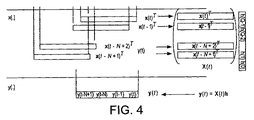
必要とされるものは、ベクトルhの推定である。このベクトルは、入力信号の単一の観察値y(t)と1つのベクトルx(t)とからだけでは、確定的に推定することができない。hに関して曖昧でない情報のために十分な情報を得るのに必要なものは、x(t)過程からの一連の「スナップショットベクトル」x(t),x(t−1),…と、y(t)過程の1つのスナップショットベクトルy(t)=[y(t−N+1),…,y(t)]とである。すると、応答スナップショットベクトルy(t)は、図4に示すように、hと「スナップショットベクトル」x(t),x(t−1),…の各々との内積によって書きかえることができる。 What is needed is an estimation of the vector h. This vector cannot be deterministically estimated from only a single observation y (t) of the input signal and one vector x (t). What is needed to obtain enough information for unambiguous information about h is a series of “snapshot vectors” x (t), x (t−1),. (T) One snapshot vector y (t) = [y (t−N + 1),..., Y (t)] in the process. Then, the response snapshot vector y (t) can be rewritten by the inner product of h and each of the “snapshot vectors” x (t), x (t−1),... As shown in FIG. .
行列のセットアップの最終バージョンは、X(t)の要素を次式のように書けることに注意することからわかる。 The final version of the matrix setup can be seen by noting that the elements of X (t) can be written as
X(t)ij=x(t−i−j) 0≦j≦Q−1,0≦i≦N−1 式(3) X (t) ij = x (t−i−j) 0 ≦ j ≦ Q−1, 0 ≦ i ≦ N−1 Formula (3)
これで、X(t)の第1列が、上から下へ時間的に逆行するように、x(t−Q+1)からx(t−Q−N+2)までのx(t)の時間スライスを含むことがわかる。X(t)の第2列は、x(t−Q+2)からx(t−Q−N+3)までのx(t)の時間スライスを含み、以下同様に、最後の列は、x(t−N+1)から時間的に逆行するx(t)の時間スライスを含む。要約すると、行列X(t)の列は、図5に示すように、x(t)の連続的な時間スライスを含んでいる。 Now, the time slice of x (t) from x (t−Q + 1) to x (t−Q−N + 2) is made so that the first column of X (t) reverses in time from top to bottom. I understand that it contains. The second column of X (t) includes x (t) time slices from x (t−Q + 2) to x (t−Q−N + 3), and so on. (N + 1) includes time slices of x (t) that are retrograde in time. In summary, the columns of the matrix X (t) contain consecutive time slices of x (t), as shown in FIG.
これで、出力信号ベクトルy(t)が、x(t)の最新のQ個の時間スナップショットベクトルによる線形結合であることがわかる。これが、上記モデルの元の提示に対応するベクトル化されたバージョンである。 Thus, it can be seen that the output signal vector y (t) is a linear combination of the latest Q time snapshot vectors of x (t). This is a vectorized version corresponding to the original presentation of the model.
行列X(t)が十分に条件付けられたものである限り、インパルス応答hは、
推定値
![]()
Estimated value
![]()
ここで、αは、予測変数におけるノイズ及び/又は共線性(co-linearity)の存在下で解の候補を縮小させるために使用される正則化パラメータである。 Where α is a regularization parameter used to reduce the solution candidates in the presence of noise and / or co-linearity in the predictor.
上の式4及び5の解は、公知である次式の通常最小二乗(ordinary least-squares:OLS)推定値及びリッジ又は最小平均二乗(LMS)推定値である。 The solutions of Equations 4 and 5 above are the ordinary least-squares (OLS) estimates and the ridge or least mean square (LMS) estimates of the following equation:
ここで、「+」演算子はムーア・ペンローズの逆行列を示す。これは当該技術において既知であり、極く簡単に言えば、これは、線形方程式の集合の解に対する、最小二乗アプローチを用いた最良の近似である。解が複数存在する場合は、L2ノルムが最小になるものが選ばれる。 Here, the “+” operator indicates Moore-Penrose inverse matrix. This is known in the art and, quite simply, it is the best approximation using a least square approach to the solution of a set of linear equations. If there are multiple solutions, the one with the smallest L2 norm is selected.
ノイズレベルが既知であれば、パラメータαは、統計的平均二乗誤差を最小化するように選定可能である。この技術は、信号処理の技術分野ではLMS法として知られている。ただしこのような場合、通常は、行列X(t)は単一の駆動信号又は圧縮パルスから受信されるサンプルのすべてを包含することが想定される。しかしながら、本発明によれば、駆動信号の部分集合のみを含む行列X(t)を使用することが提案される。このことは、最初の送信より前に信号が消滅するのを待機する必要なしに、hの推定値が経時的に更新されることを可能にする。これにより、スライディングサンプルウィンドウが効果的にもたらされる。 If the noise level is known, the parameter α can be selected to minimize the statistical mean square error. This technique is known as the LMS method in the field of signal processing. However, in such cases, it is usually assumed that the matrix X (t) encompasses all of the samples received from a single drive signal or compressed pulse. However, according to the invention, it is proposed to use a matrix X (t) containing only a subset of the drive signals. This allows the estimate of h to be updated over time without having to wait for the signal to disappear before the first transmission. This effectively provides a sliding sample window.
LMS法による上述のスライディングウィンドウの定式化は、本質的には、単一のパルス又は重複を避けるように離隔された複数のパルスのみを使用するものとは対照的な、連続なLMS法である。これは、離散サンプルではなく信号の時間連続(すなわち、アナログ)表現を有していることを単に示している、時間連続なLMS法と混同されるべきではない。 The above sliding window formulation by the LMS method is essentially a continuous LMS method as opposed to using only a single pulse or multiple pulses separated to avoid overlap. . This should not be confused with the time-continuous LMS method, which simply indicates that it has a time-continuous (ie analog) representation of the signal rather than discrete samples.
これまでに述べた分析から、送信信号の計算された逆行列、例えば擬似逆行列を受信信号へ適用すると、送信信号の全体にわたる相互の直交性を必要とすることなく、音響チャンネルの優れた推定が得られることがわかる。事実、性能を決定する重要なファクタは、送信信号の個々の部分が互いに線形独立になっている度合いである。これは、相互に直交していることよりも、条件の厳しさに関してははるかにゆるいものである。線形独立であることの重要性は式(5)から生じるが、ここでは、信号の複数の部分を可能な限り線形独立にすることでチャンネル推定の曖昧さが最小化される。このような曖昧さは行列X(t)の条件付けの品質を低下させ、結果的に、先の式(4)に対してより多くの可能な解をもたらしてしまう。さらに、X(t)の複数の列における共線性はX(t)がいくつかの小さな特異値を有することを含意するので、hの推定の分散は増大し、延いてはこれが、例えば擬似逆行列の演算の際に、付加的ノイズ成分を拡大させるように影響する。 From the analysis described so far, applying a calculated inverse matrix of the transmitted signal, for example a pseudo-inverse, to the received signal provides an excellent estimate of the acoustic channel without requiring mutual orthogonality across the transmitted signal. It can be seen that In fact, an important factor that determines performance is the degree to which the individual parts of the transmitted signal are linearly independent of each other. This is much looser with respect to the severity of conditions than being orthogonal to each other. The importance of being linearly independent arises from equation (5), where channel estimation ambiguity is minimized by making portions of the signal as linearly independent as possible. Such ambiguity degrades the conditioning quality of the matrix X (t) and results in more possible solutions to the previous equation (4). Furthermore, the collinearity in multiple columns of X (t) implies that X (t) has several small singular values, so that the variance of the estimate of h increases, which in turn is, for example, pseudo-inverse When the matrix is calculated, an additional noise component is affected.
後に示すように、本発明の逆行列演算技術は、先に述べた構造的ノイズの問題から被る悪影響がはるかに少ない。その理由は、この構造的ノイズが受信信号の一部を形成していて、計算された逆行列がこれに適用されるということにある。これには、構造的ノイズをランダム化又は白色化し、よって平均化を容易にするという効果のあることがわかる。 As will be shown later, the inverse matrix operation technique of the present invention has much less adverse effects from the structural noise problem described above. The reason is that this structural noise forms part of the received signal and the computed inverse matrix is applied to it. It can be seen that this has the effect of randomizing or whitening the structural noise, thus facilitating averaging.
擬似逆行列等の逆行列の計算が計算集約的なタスクである点は、重要な考慮事項である。必要な逆行列は、受信信号へ当該逆行列を適用するのと同時に、又はその直前に計算可能である。簡単なアプリケーションでは、インパルス信号の送信時にこれをリアルタイムで行うことも可能である。しかしながら、これでは、達成可能な分解能(時間及び空間の双方)が制限される。これに対処するため、チャンネル推定は事後の遡及的分析として実行されてもよい。しかしながら、これは、多くのアプリケーションにとって不適切であろう。 An important consideration is that computation of inverse matrices such as pseudo-inverse is a computationally intensive task. The required inverse matrix can be calculated simultaneously with or just before applying the inverse matrix to the received signal. In simple applications, this can be done in real time when the impulse signal is transmitted. However, this limits the achievable resolution (both time and space). To address this, channel estimation may be performed as a retrospective retrospective analysis. However, this may be inappropriate for many applications.
しかしながら、好適には、逆行列はインパルス信号の送信に先立って計算される。本願出願人は、これを行う能力が本発明に係る好適な方法の重要な優位点であると認識している。このことは、分解能の大幅な制限又は高価な処理パワーの要件なしにリアルタイム実装を可能にする。計算された逆行列、例えばX(t)+は、予め決められた信号x(t)から事前に計算されてメモリに格納され、次いでy(t)におけるサンプルのスナップショットベクトルと事前に乗算するためのルックアップ表として使用されることが可能である。リアルタイムの逆行列演算は、不要である。この利点の意義は、これを、特許文献1に記載されている最近の従来技術による教示と比較すればより良く理解することができる。特許文献1では、応答信号y(t)の時間サンプルから構成される行列の逆行列を演算することが必要であるようにモデルが構築され、この場合、測定後の逆行列演算が不可避である。従って、特許文献1における教示内容では、分散されたネットワーク上の多数のコンピュータ間で必要な処理を分割する方法に重点が置かれている。これに対して、本発明の一実施形態は、後述するように、標準的なデスクトップ型パーソナルコンピュータ上への実装に成功している。
Preferably, however, the inverse matrix is calculated prior to transmission of the impulse signal. Applicants recognize that the ability to do this is an important advantage of the preferred method according to the present invention. This allows real-time implementation without significant resolution limitations or expensive processing power requirements. The computed inverse matrix, eg, X (t) +, is pre-computed from a predetermined signal x (t) and stored in memory, then pre-multiplied with the sample's snapshot vector at y (t). Can be used as a lookup table for. Real-time inverse matrix operation is not required. The significance of this advantage can be better understood when compared to the recent prior art teaching described in US Pat. In
受信信号は、通常、環境におけるオブジェクトの表面からの反射と、信号が伝搬する媒体(例えば、音響信号の場合は空気)の影響との結果である。しかしながらまた、受信信号は、環境の一部を反射せずに通過している可能性もある。このことは、例えば、送信機(もしくは送信機が取り付けられたオブジェクト)を空間中で位置決めするための簡単なシステムの場合にあてはまる可能性がある。 The received signal is usually the result of reflections from the surface of the object in the environment and the influence of the medium through which the signal propagates (eg, air in the case of acoustic signals). However, the received signal may also pass through a portion of the environment without reflection. This may be the case, for example, in the case of a simple system for positioning a transmitter (or an object with a transmitter attached) in space.
送信信号、延いては受信される応答は、使用されるハードウェアの制約内のブロードバンド信号である可能性がある。しかしながら、少なくともいくつかの好適な実施形態では、これらの帯域幅は意図的に制限される。制限なしであればブロードバンドである信号の帯域幅を制限することは、信号に冗長性を導入することに相当するので、これは、チャンネル推定の計算に要する計算量を削減する点で効果的である。 The transmitted signal, and hence the received response, can be a broadband signal within the constraints of the hardware used. However, in at least some preferred embodiments, these bandwidths are intentionally limited. If there is no limit, limiting the bandwidth of a broadband signal is equivalent to introducing redundancy in the signal, which is effective in reducing the amount of computation required to calculate the channel estimate. is there.
一例を挙げると、帯域幅は、そのもとの範囲の3分の1まで制限されてもよい。行列演算に含まれる全内積との密接な相関を達成するには、本来必要とされたであろう内積における乗算回数の約3分の1で足りるので、完全なベクトルから抽出されるベクトル要素がエイリアシング効果を生じないように選定されていれば、送信されるインパルスx(t)及び受信される信号y(t)における後続の時間サンプルは所定の程度の冗長性を呈示する。 As an example, the bandwidth may be limited to one third of its original range. In order to achieve a close correlation with the total dot product included in the matrix operation, approximately one third of the number of multiplications in the inner product that would have been originally required is sufficient, so that the vector element extracted from the complete vector is If selected to produce no aliasing effect, subsequent time samples in the transmitted impulse x (t) and the received signal y (t) exhibit a certain degree of redundancy.
さらに、送信信号x(t)及び受信信号y(t)の帯域が制限される場合は、チャンネル推定値
![]()
![]()
![]()
![]()
![]()
![]()
ある好適な実施形態の集合では、チャンネル推定は、環境のあらゆる特徴をモニタリングするために使用される。例えば、これは、石油探査にとって大きな価値をもつ海底面を測定するために使用可能である。この場合の「チャンネル」は、海底と、介在する海水である。本発明に従って達成され得る優位点は、十分な分解能を保ちながら、従来技術を使用する場合よりはるかに迅速に海底を走査できることにある。これは、送信した信号が消滅するのを待つ必要がなくかつ可能な限り高度に相互に直交する複数の送信符号を構築する必要なしにチャンネル推定の連続的な更新をもたらす、本発明により与えられる能力の成果である。このような実施形態の他の例としては、医療法画像化処理、セキュリティのスキャン処理、ロボットビジョン等がある。 In a set of preferred embodiments, channel estimation is used to monitor every feature of the environment. For example, it can be used to measure the sea floor, which has great value for oil exploration. The “channel” in this case is the seabed and intervening seawater. An advantage that can be achieved in accordance with the present invention is that it can scan the seabed much more quickly than with the prior art while maintaining sufficient resolution. This is given by the present invention which results in a continuous update of the channel estimate without having to wait for the transmitted signal to disappear and without having to construct multiple transmission codes that are as mutually orthogonal as possible It is a result of ability. Other examples of such embodiments include medical law imaging processing, security scanning processing, robot vision, and the like.
さらなる態様から見ると、本発明は、環境をマッピングする方法を提供し、本方法は、インパルス信号を上記環境へ送信することと、上記環境からの戻り信号を検出することと、上記インパルス信号の計算された逆行列を上記戻り信号へ適用することとを含む。 Viewed from a further aspect, the present invention provides a method of mapping an environment, the method transmitting an impulse signal to the environment, detecting a return signal from the environment, and detecting the impulse signal. Applying the calculated inverse matrix to the return signal.
また、インパルス信号を環境へ送信する手段と、上記環境からの戻り信号を検出しかつ上記インパルス信号の計算された逆行列を上記戻り信号へ適用する手段とを備える、環境をマッピングするためのマッピング装置も提供される。 A mapping for mapping the environment, comprising: means for transmitting the impulse signal to the environment; and means for detecting the return signal from the environment and applying the calculated inverse matrix of the impulse signal to the return signal. An apparatus is also provided.
本発明はまた、環境へ送信されるインパルス信号の計算された逆行列を上記環境からの戻り信号へ適用する手段と、これにより上記環境の表現を計算する手段とを備える、環境をマッピングするためのコンピュータソフトウェア製品を包含する。 The present invention also provides for mapping an environment comprising means for applying a calculated inverse matrix of an impulse signal transmitted to the environment to a return signal from the environment and thereby calculating a representation of the environment. Including computer software products.
好適には、上記マッピング方法は、推定されたチャンネル応答に基づいて位置ダイアグラムを構築することを含む。これは、連続したインパルス応答推定値が互いに隣接して提示された表現である。このようなダイアグラム内の特徴部分、例えば反射体の端又は中心は、次に、標準的な画像処理技術を用いて識別可能である。例えば、海底等の地形上において定速で送信機を移動させることによって、海底のプロファイルがスキャンされる。 Preferably, the mapping method includes constructing a location diagram based on the estimated channel response. This is a representation in which successive impulse response estimates are presented adjacent to each other. Features in such a diagram, such as the edge or center of the reflector, can then be identified using standard image processing techniques. For example, the seabed profile is scanned by moving the transmitter at a constant speed on topography such as the seabed.
別の好適な実施形態の集合では、チャンネル推定は、移動するオブジェクトの追跡に使用される。この場合の「チャンネル」は、オブジェクト及び周囲の空間である。ここでは、チャンネル推定を連続的に更新する能力が不可欠である。このようなアプリケーションは、オブジェクトが非常にゆっくりと移動しているか、非常に低い空間分解能で十分であるというのではない限り、従来技術の送信−受信−待機技術では当然ながら不可能である。以下の例でわかるように、本発明の一実施形態によれば、標準的なデスクトップPCと、一般的なPCラウドスピーカと、2つの一般的なマイクロホンとを用いて、指先の高速移動をミリメートル未満の精度で追跡し得ることが示されている。これは、物理的接触の必要性を取り除いた人間とマシンとのインターフェースにおいて、多くの可能なアプリケーションを有する。本願出願人が企図するこのようなアプリケーションのうちの特定の1つは、特に病院における、医療機器のためのインターフェースにおけるものであり、病院では、物理的接触の必要性の回避によって、機器を介した相互感染の危険性が低下する。 In another set of preferred embodiments, channel estimation is used to track moving objects. The “channel” in this case is the object and the surrounding space. Here, the ability to continuously update the channel estimate is essential. Such an application is of course not possible with prior art transmit-receive-wait techniques unless the object is moving very slowly or a very low spatial resolution is sufficient. As can be seen in the following example, according to one embodiment of the present invention, a standard desktop PC, a typical PC loudspeaker, and two common microphones are used to provide fast fingertip movement in millimeters. It has been shown that it can be tracked with less accuracy. This has many possible applications in the human-machine interface that eliminates the need for physical contact. One particular such application contemplated by the Applicant is in an interface for a medical device, particularly in a hospital, where the intervention of the device is avoided by avoiding the need for physical contact. The risk of mutual infection is reduced.
さらに他の態様から見ると、本発明はオブジェクトを追跡する方法を提供し、本方法は、インパルス信号を送信することと、上記オブジェクトからの上記インパルス信号の反射を記録することと、上記インパルス信号の計算された逆行列を上記反射された信号へ適用することとを含む。 Viewed from yet another aspect, the present invention provides a method for tracking an object, the method comprising transmitting an impulse signal, recording a reflection of the impulse signal from the object, and the impulse signal. Applying the calculated inverse matrix to the reflected signal.
好適には、上記方法はさらに、推定されたチャンネル応答に基づいて位置ダイアグラムを構築することと、例えば追跡されているオブジェクトの位置を計算するために適切な画像処理技術を用いて、上記位置ダイアグラムを解釈することとを含む。 Preferably, the method further comprises constructing a position diagram based on the estimated channel response and using, for example, an appropriate image processing technique to calculate the position of the tracked object. Interpreting.
また、送信手段と、受信手段と、処理手段とを備える追跡装置も提供され、上記処理手段は、上記送信手段によって送信されたインパルス信号の計算された逆行列を、上記受信手段によって受信された信号へ適用するように構成される。 There is also provided a tracking device comprising a transmitting means, a receiving means, and a processing means, wherein the processing means has received the calculated inverse matrix of the impulse signal transmitted by the transmitting means by the receiving means. Configured to apply to a signal.
本発明はまた、オブジェクトへ向けて環境内へ送信されるインパルス信号の計算された逆行列を、上記オブジェクトから反射される戻り信号へ適用する手段と、これにより、上記オブジェクトのロケーションを計算する手段とを備える、オブジェクトを追跡するためのコンピュータソフトウェア製品を包含する。 The invention also provides means for applying a computed inverse matrix of impulse signals transmitted into the environment towards the object to the return signal reflected from the object, thereby calculating the location of the object A computer software product for tracking objects comprising:
一般に、組み合わされた一対の送信機及び受信機毎に、1次元での追跡が可能になる。従って、2次元の追跡を行う場合は、2つの受信機、又は好適には2つの送信機が必要である。これらの2つの場合において、共通の送信機又は受信機がそれぞれ使用可能である。しかしながら、このことは必須ではなく、代わりに別々のものが使用されてもよい。2つの送信機は、独立した信号によって駆動されてもよい。あるいは、これらは同じ信号によって駆動されてもよいが、ただし、このとき各信号には互いに時間遅延が付加されている。このことは、信号が互いに区別されることを可能にする。これと同じ効果は、送信機のうちの1つを追跡領域から物理的にオフセットすることによっても達成可能である。 In general, one-dimensional tracking is possible for each pair of combined transmitter and receiver. Thus, for two-dimensional tracking, two receivers, or preferably two transmitters, are required. In these two cases, a common transmitter or receiver can each be used. However, this is not essential and a separate one may be used instead. The two transmitters may be driven by independent signals. Alternatively, they may be driven by the same signal, but at this time each signal has a time delay added to it. This allows the signals to be distinguished from one another. This same effect can be achieved by physically offsetting one of the transmitters from the tracking area.
いくつかの企図される実施形態では、2つの送信機、例えばラウドスピーカは、同じ周波数帯からの信号のそれぞれによって駆動され、これらの信号は受信機において分離される。これは、以下の説明から理解することができる。 In some contemplated embodiments, two transmitters, eg, loudspeakers, are driven by each of the signals from the same frequency band, and these signals are separated at the receiver. This can be understood from the following description.
受信機(例えば、マイクロホン)で受信される信号は、送信された(そして畳み込まれた)信号の合成信号である。 The signal received at the receiver (eg, microphone) is a composite signal of the transmitted (and convolved) signal.
y(t)=h1(t)*x1(t)+h2(t)*x2(t) 式(6a) y (t) = h 1 (t) * x 1 (t) + h 2 (t) * x 2 (t) Equation (6a)
これは、行列/ベクトル表記では次式になる。 This is expressed by the following equation in matrix / vector notation.
ここで、以下の表記を用いた。 Here, the following notation was used.
X(t)=[X1(t)X2(t)]
h(t)=[h1(t)Th2(t)T]T
X (t) = [X 1 (t) X 2 (t)]
h (t) = [h 1 (t) T h 2 (t) T] T
本発明に係る方法を使用すれば、誤差及び摂動に関して結果が安定であるように行列X(t)の大きさが選定されることを保証しながら、インパルス応答h1(t)及びh2(t)の双方を含むベクトルh(t)を推定することができる。 Using the method according to the invention, the impulse responses h 1 (t) and h 2 (( 2 ) are chosen while ensuring that the size of the matrix X (t) is chosen so that the result is stable with respect to errors and perturbations. A vector h (t) containing both t) can be estimated.
当然ながら、3次元追跡では、余分な送信機又は受信機を追加することができる。本発明の方法は、理想的には、前述の分析から理解できるように、複数の送信機及び受信機とともに使用されることに適する。例えば、これらの複数の構成要素は、アレイ処理や、アレイ画像生成及び分析を実行するために使用されてもよい。実際に、本発明の方法は、本発明の方法を使用できるアプリケーションと音声及び画像生成技術との分野において大きな効力を有する。これは、実際の演算より前に信号行列の逆行列を演算することによりもたらされる、計算集約的な演算を実行する能力に由来する。 Of course, in 3D tracking, extra transmitters or receivers can be added. The method of the present invention is ideally suited for use with multiple transmitters and receivers, as can be appreciated from the foregoing analysis. For example, these multiple components may be used to perform array processing and array image generation and analysis. In fact, the method of the present invention has great effect in the field of applications and audio and image generation techniques that can use the method of the present invention. This stems from the ability to perform computationally intensive operations resulting from computing the inverse of the signal matrix prior to the actual operation.
オブジェクトを2次元又は3次元で位置決めするためには、異なる信号が適切に合成されなければならない。好適には、異なる信号に対応するインパルス応答推定を合成して、追跡されているオブジェクトを位置決めするためには、楕円の交差が使用される。言いかえれば、インパルス応答のピークを強い反射体によるものであると解釈することにより、反射体は、受信機/送信機を焦点として有し、送信機から反射体へ到達して戻る伝搬時間により与えられる径を有する楕円面上に存在するものとみなされる。複数の送信機/受信機が使用されれば、反射体は受信機−送信機の伝搬時間の3つ組に対応する楕円面の交点に存在し、これらの楕円面の共通の交点として識別されることが可能である。 In order to position an object in two or three dimensions, different signals must be properly synthesized. Preferably, elliptical intersections are used to synthesize impulse response estimates corresponding to different signals to locate the object being tracked. In other words, by interpreting the peak of the impulse response as being due to a strong reflector, the reflector has a receiver / transmitter as the focal point, and the propagation time from the transmitter to the reflector and back It is considered to exist on an ellipsoid having a given diameter. If multiple transmitters / receivers are used, the reflector is present at the intersection of ellipsoids corresponding to the receiver-transmitter propagation time triple and is identified as the common intersection of these ellipsoids. Is possible.
本発明に係る上述のマッピング及び追跡の用途は、共通する重要な特徴を有する。すなわち、受信機は送信機が生成するインパルスに対するチャンネルの応答のみを受信して分析するという意味で、これらは閉じたものである。実際に、本発明の場合は一般にはこのことは事実であり、送信機と受信機との間で情報は伝達されない。本発明は、送信される内容を、それが計算された逆行列に変形されているにしても、受信機が正確に認識しているということに基づくものである。「情報」は逆行列の計算に必要とされるので、論理的には情報は伝達可能ではない。 The above mapping and tracking applications according to the present invention have important features in common. That is, the receiver is closed in the sense that the receiver only receives and analyzes the channel response to the impulse generated by the transmitter. In fact, this is generally the case with the present invention, and no information is communicated between the transmitter and the receiver. The present invention is based on the fact that the receiver correctly recognizes the content to be transmitted, even if it has been transformed into a computed inverse matrix. Since “information” is required for calculation of an inverse matrix, information cannot be transmitted logically.
好適には、送信される信号と受信される応答とに使用されるサンプリングレートは同じである。しかしながら、これは必須ではなく、異なる場合もある。サンプリングレートとしては、アプリケーション及び要求される分解能に依存して、数ヘルツからギガヘルツまでの何れかの値が使用可能である。 Preferably, the sampling rate used for the transmitted signal and the received response is the same. However, this is not essential and may be different. As the sampling rate, any value from several hertz to gigahertz can be used depending on the application and the required resolution.
本願出願人は、本発明に従って説明している連続なLMS法が、残存エコー及びノイズに対して頑健であるゆえに効果的であることを認識している。以下、このことを説明する。式(1)に残存エコー及びノイズの双方を包含させると、次式になる。 Applicants have recognized that the continuous LMS method described in accordance with the present invention is effective because it is robust to residual echo and noise. This will be described below. When both residual echo and noise are included in the equation (1), the following equation is obtained.
ここで、n(t)はチャンネルノイズであり、s(t)は残存エコーからの寄与分である。このエコーは、明らかに、信号x(t)のうちの何らかの先行部分がフィルタリングされたものになる。言いかえれば、s(t)への寄与分は、前述の分析で検討したベクトル[x(t−Q+1),…,x(t)]に含まれるものよりも先行するx(t)のサンプルから生じるもののはずである。これらの先行するサンプルは、ベクトルh内に保持されるタップの外部にある障害又は影響に対応する別のフィルタタップと畳み込み演算される。これらの別のタップは、フィルタg(t)によって、次式のように表される。 Here, n (t) is channel noise, and s (t) is a contribution from the remaining echo. This echo is clearly a filtered version of some previous part of the signal x (t). In other words, the contribution to s (t) is a sample of x (t) that precedes that contained in the vector [x (t−Q + 1),..., X (t)] examined in the above analysis. Should come from. These preceding samples are convolved with another filter tap corresponding to a fault or effect outside the tap held in vector h. These other taps are represented by the filter g (t) as follows:
ここで、Mは最大残響時間(又はエコーの残存時間)である。行列表記に移行すると、式(7)及び(8)は、ブロック形式では次式のように表される。 Here, M is the maximum reverberation time (or echo remaining time). When shifting to matrix notation, equations (7) and (8) are expressed in the block form as follows:
y(t)=X(t)h+X2(t)g+n(t) 式(9) y (t) = X (t) h + X 2 (t) g + n (t) Equation (9)
ここで、X2(t)は、中心のQタップウィンドウの外側にある、上述の行列形式による信号の一部を含み、gは、「ウィンドウの外」のフィルタタップによるベクトルであり、n(t)は、付加的チャンネルノイズを含むベクトルである。 Where X 2 (t) includes a portion of the signal in the matrix format described above that is outside the central Q tap window, g is a vector with “out of window” filter taps, and n ( t) is a vector containing additional channel noise.
本発明に係る逆行列演算技術を使用し、上述の式(9)に擬似逆行列X(t)+を左から乗算すると、次式が得られる。 Using the inverse matrix calculation technique according to the present invention and multiplying the above equation (9) by the pseudo inverse matrix X (t) + from the left, the following equation is obtained.
ここで、以下の表記を用いた。 Here, the following notation was used.
m(t)=X(t)+X2(t)g+X(t)+n(t) m (t) = X (t ) + X 2 (t) g + X (t) + n (t)
2行目の右辺の第1項に関して、X(t)+X(t)=Iであれば、
![]()
![]()
![]()
![]()
![]()
![]()
本発明を使用する方法及び装置は、相互相関を使用するものよりも効果的であることを先に述べた。以下、これについて説明するが、まずは、本明細書で言及した相互相関の動作方法について説明する。 It was mentioned earlier that the method and apparatus using the present invention is more effective than using cross-correlation. This will be described below, but first, the cross correlation operation method referred to in this specification will be described.
信号x(t)がラウドスピーカを介して送信されたと仮定すると、これは、マイクロホンを介して同じくy(t)として受信される。受信信号y(t)は、送信信号に対して、次式のように関連しているものと考えられる。 Assuming that the signal x (t) was transmitted via a loudspeaker, this is also received as y (t) via a microphone. The reception signal y (t) is considered to be related to the transmission signal as follows.
すなわち、y(t)のあるサンプルは、x(t)における最後のK個のサンプルの線形結合であり、線形重みは「フィルタ係数」h(0),…,h(K−1)において与えられる。チャンネルを推定するためには、これらのフィルタ係数を推定することが必要である。この技術において、信号x(t)は、負の無限大から正の無限大までのすべてのtについて「白色」であると仮定される。言いかえれば、信号はすべての非ゼロシフトについて当該信号自体と無相関であると仮定されている。このことは次式のように表される。 That is, a sample with y (t) is a linear combination of the last K samples in x (t), and the linear weights are given in “filter coefficients” h (0),..., H (K−1). It is done. In order to estimate the channel, it is necessary to estimate these filter coefficients. In this technique, the signal x (t) is assumed to be “white” for all t from negative infinity to positive infinity. In other words, the signal is assumed to be uncorrelated with the signal itself for all non-zero shifts. This is expressed as follows:
ここで、Pは正の実数である。 Here, P is a positive real number.
信号と、その信号自体の時間反転したものとの畳み込み演算を行うことは、その信号自体との相関、すなわち信号の自動相関を計算することと同じである。よって、x(t)が実際に白色であることを仮定すれば、x(t)をそれ自体と相関させることにより、時間ラグ0の場合は正の値Pが生じ、その他のすべての場合ではゼロが生じる。これを別の方法で表記すると、次式になる。
Performing a convolution operation between a signal and a time-inverted version of the signal is the same as calculating a correlation with the signal itself, that is, an automatic correlation of the signal. Thus, assuming x (t) is actually white, correlating x (t) with itself yields a positive value P in the case of
x(t)*x(−t)=P・∂(t) 式(C) x (t) * x (−t) = P · ∂ (t) Formula (C)
ここで、∂(t)はディラックのデルタ関数である。 Here, ∂ (t) is a Dirac delta function.
ここで、次式のように、N+1個のサンプル長及びx(t)の時間ウィンドウで、時間軸上の点t0のほぼ周辺においても式(B)が成り立つと仮定する。 Here, as shown in the following equation, it is assumed that the equation (B) is established also in the vicinity of the point t 0 on the time axis in the time window of N + 1 sample lengths and x (t).
t0の周囲でy(t)とx(−t)との畳み込みを行うと、次式が得られる。 When convolution of y (t) and x (−t) is performed around t 0 , the following equation is obtained.
この和における内項を計算すると、次式が得られる。 When the inner term in this sum is calculated, the following equation is obtained.
よって、次式が得られる。 Therefore, the following equation is obtained.
上記式(D)からわかるように、式(G)における括弧内の項は、l=iのとき、かつそのときに限り(およそ)Pであり、そうでなければ(およそ)0である。ゆえに、l=1を選ぶことにより、畳み込み
![]()
![]()
上述の相互相関法は、式(5及び6)において本発明の説明のために用いたものと同様の枠組みに当てはめることが可能である。この場合、推定量は、次式になるであろう。 The cross-correlation method described above can be applied to a framework similar to that used to describe the present invention in equations (5 and 6). In this case, the estimator would be
![]()
![]()
これは、低品質の推定量である。X(t)が直交行列である場合、解は、LS又はLMS又はリッジ推定量(スケーリング定数まで)と同一になる。しかしながら、一般には、関連したスライディングウィンドウ行列X(t)が一般に直交行列であるという特性を有する時系列x(t)を構築することは困難である。これは、直交符号の形式をとる比較的長さの短いシーケンスを発見するという問題点に起因する。その結果、相互相関に基づく方法では符号シーケンスの選択が不可欠であるが、連続なLMS法ではさほど重要ではない。 This is a low quality estimator. If X (t) is an orthogonal matrix, the solution will be the same as the LS or LMS or ridge estimator (up to the scaling constant). However, in general, it is difficult to construct a time series x (t) having the property that the associated sliding window matrix X (t) is generally an orthogonal matrix. This is due to the problem of finding a relatively short sequence in the form of an orthogonal code. As a result, code sequence selection is essential for cross-correlation based methods, but less important for continuous LMS methods.
図6は、インパルス応答推定のシーケンスの例を示したものである。本例は、インパルス応答は変化しない人為的に作った場合の事例であるが、これは相対的な分解能の明確性を示そうとするためのものである。画像の縦のスライスは、連続した時点におけるインパルス応答推定値に対応し、すなわち、画像は先に述べた位置ダイアグラムである。左側のパネルには、相互相関法を用いて得られた結果が示され、右側のパネルでは、本発明に係る連続なLMS法が使用されている。相互相関の画像では望ましくないアーティファクトの存在が明らかであり、LMSに比べて、その後の追跡タスクはより困難になる。 FIG. 6 shows an example of an impulse response estimation sequence. In this example, the impulse response is artificially generated and does not change, but this is intended to show the relative resolution clarity. The vertical slice of the image corresponds to the impulse response estimate at successive times, i.e. the image is the position diagram described above. The left panel shows the results obtained using the cross-correlation method, and the right panel uses the continuous LMS method according to the present invention. The presence of undesirable artifacts is evident in cross-correlation images, making subsequent tracking tasks more difficult compared to LMS.
少なくともいくつかの好適な実施形態において述べたように、帯域幅は、使用されるハードウェアの制約を超えて意図的に制限される。これは、次に説明するように、必要な計算量の低減において優位点を有する。 As stated in at least some preferred embodiments, bandwidth is intentionally limited beyond the constraints of the hardware used. This has an advantage in reducing the amount of calculation required, as will be explained next.
信号の帯域が制限される場合、信号x(t)には時間的な冗長度が存在し、よって、行列X(t)の行及び列も冗長性を帯びる。この影響で、行列X(t)の階数は下がる。これにより、真のインパルス応答hの推定精度は低下させられるが、計算量もずっと削減することができる。 When the signal bandwidth is limited, there is temporal redundancy in the signal x (t), so the rows and columns of the matrix X (t) are also redundant. Due to this influence, the rank of the matrix X (t) decreases. As a result, the estimation accuracy of the true impulse response h can be reduced, but the amount of calculation can also be reduced.
ここで、次式を、X(t)の節約された特異値分解であるとする。 Here, it is assumed that the following equation is a saved singular value decomposition of X (t).
ここで、{σi}は非ゼロの特異値であり、{ui,vi}は左側及び右側の特異ベクトルである。行列U=(u1,u2,…,ur),V=(v1,v2,…,vr),及びS=diag(σ1,σ2,…,σr)は、個数r=rank(X(t))の左右の特異ベクトル及び特異値をそれぞれ含む。X(t)が高度に共線的であれば、特異値の多くはゼロに近くなる。このことは、以下の近似を可能にする。
Here, {σ i } is a non-zero singular value, and {u i , v i } are left and right singular vectors. Matrix U = (u 1, u 2 , ..., u r), V = (
これは、X(t)のk成分近似である。行列Uk,Sk,Vkは、この行列の最初のk個の特異ベクトル及び特異値のみを含む。さらに、これで、X(t)の擬似逆行列推定を、次式で表すことができる。 This is an approximation of the k component of X (t). The matrices U k , S k and V k contain only the first k singular vectors and singular values of this matrix. Further, the pseudo inverse matrix estimation of X (t) can be expressed by the following equation.
この時点で、行列Uk,Sk,Vkは削減された個数の列及び行を有するので、T及びPは、次式により表される。 At this point, since the matrices U k , S k , and V k have a reduced number of columns and rows, T and P are expressed by the following equations.
T=VkSk −1
P=Uk T
T = V k S k −1
P = U k T
X(t)が(N×Q)行列であれば、X(t)+は(Q×N)になり、ゆえに、TはQ×Kになり、Pは(N×K)になる。チャンネルhを推定するためにX(t)の擬似逆行列を適用すると、次式になる。 If X (t) is an (N × Q) matrix, X (t) + becomes (Q × N), so T becomes Q × K and P becomes (N × K). When a pseudo inverse matrix of X (t) is applied to estimate the channel h, the following equation is obtained.
![]()
![]()
ここで、積Py(t)の計算にはN×K回の演算(乗算及び和演算)が必要であり、結果Py(t)とTとの積の計算にはQ×K回の演算が必要である。このことは、総演算回数が(N+Q)×Kであることを意味する。元の方法の代替方法は、直にX(t)+との乗算を行うため、N×Q回の演算が必要である。N=200,Q=70及びK=Q/3〜23が、X(t)に係るランクが削減されかつ十分に良好な推定をもたらす場合(典型的には、元の周波数帯の1/3に制限された信号を使用するとき)では、y(t)とX(t)+との乗算の総演算回数は200×70=14000になるが、これに対して、y(t)にまずPを乗算して次にTを乗算すると、合計の演算回数は(N+Q)×K=(200+70)*23=6210になる。このことは、演算時間の半分以上が節約されたことを意味する。提案している低減の実装は、各時間ウィンドウにつき、1つの(X(t)+)ではなく、2組の行列T,Pを格納することを含む。 Here, the calculation of the product Py (t) requires N × K operations (multiplication and summation), and the product of the result Py (t) and T requires Q × K operations. is necessary. This means that the total number of calculations is (N + Q) × K. Since the alternative method of the original method directly performs multiplication with X (t) + , N × Q operations are required. N = 200, Q = 70 and K = Q / 3-23 if the rank for X (t) is reduced and yields a sufficiently good estimate (typically 1/3 of the original frequency band) (When using a signal limited to 2), the total number of multiplications of y (t) and X (t) + is 200 × 70 = 14000. When multiplying by P and then by T, the total number of operations is (N + Q) × K = (200 + 70) * 23 = 6210. This means that more than half of the computation time has been saved. The proposed reduction implementation involves storing two sets of matrices T and P instead of one (X (t) + ) for each time window.
上記内容は、本発明のさらに好適な特徴をもたらす。本発明の方法に係る少なくともいくつかの好適な実装においては、計算された逆行列は、インパルス信号行列の特異値分解の部分集合から導出される一対の行列を含み、本方法は、これらの行列に、上記受信信号のサンプルを含むベクトルを乗算するステップを含む。好適には、本方法はさらに、上記受信信号のサンプルの部分集合を選択して部分集合ベクトルを生成することと、上記一対の行列に上記部分集合ベクトルを乗算することとを含む。 The above contents provide further preferable features of the present invention. In at least some preferred implementations of the method of the present invention, the computed inverse matrix includes a pair of matrices derived from a subset of the singular value decomposition of the impulse signal matrix, the method comprising these matrices The step of multiplying the received signal sample by a vector. Preferably, the method further includes selecting a subset of samples of the received signal to generate a subset vector and multiplying the pair of matrices by the subset vector.
別の好適な特徴によれば、本方法は、上記逆行列の行及び/又は列の部分集合を計算することと、上記部分集合間での補間演算を行って上記計算された逆行列を完成させることとを含む。 According to another preferred feature, the method completes the calculated inverse matrix by calculating a subset of rows and / or columns of the inverse matrix and performing an interpolation operation between the subsets. Including.
次に、本発明の実装例について説明する。ただし、これは理解を助ける目的で行うものであり、本発明の範囲を限定するものとして理解されるべきではない。 Next, an implementation example of the present invention will be described. However, this is done to aid understanding and should not be understood as limiting the scope of the invention.
サウンドカードにより駆動される標準的なPCラウドスピーカを用いて、指先追跡システムを構築した。サウンドカードには、反射される信号を記録するために2つの標準的なPCマイクロホンも接続した。当然ながら、専用の超音波トランスデューサ又はハイドロホンを代わりに使用してもよい。 A fingertip tracking system was constructed using a standard PC loudspeaker driven by a sound card. The sound card was also connected with two standard PC microphones to record the reflected signal. Of course, a dedicated ultrasonic transducer or hydrophone may be used instead.
0乃至20kHzの帯域におけるディジタル白色ノイズをディジタル信号プロセッサ(DSP)により生成し、ここで、各時間サンプルは区間[−1,1]から引き出され、上記ディジタル白色ノイズを、ディジタル−アナログ変換器を介してサウンドカードへ送り、よってラウドスピーカまで送った。マイクロホンから受信される信号は、サウンドカードを介してアナログ−ディジタル変換器(すなわち、サンプラ)へ向けて送った。約22kHzのサンプリングレートを使用した。サンプリングされた信号は、DSPへ送った。DSPはまた、送信信号の予め計算された擬似逆行列を保持するメモリ記憶装置にも接続されている。これは、次に、所定のウィンドウ内の受信される応答サンプルの行列を予め乗算するために使用される。 Digital white noise in the 0-20 kHz band is generated by a digital signal processor (DSP), where each time sample is derived from the interval [-1, 1] and the digital white noise is converted into a digital-analog converter. To the sound card and thus to the loudspeaker. The signal received from the microphone was sent to the analog-to-digital converter (ie, sampler) via the sound card. A sampling rate of about 22 kHz was used. The sampled signal was sent to the DSP. The DSP is also connected to a memory storage device that holds a pre-calculated pseudo-inverse of the transmitted signal. This is then used to premultiply the matrix of response samples received within a given window.
典型的なパラメータは、以下の通りである。行列X(t)の大きさを200×70であるように選択し(x(t)信号の200個のスナップショットを用いて70個のフィルタタップを推定する)、インパルス応答推定の更新を毎秒100回行うと、合計で毎秒200×70×100=140万回の乗算及び加算演算、又は1.4メガフロップになる。これは、バックグラウンド演算としてソフトウェアで実装したり、又は安価なDSP上で実行したりすることが可能な、適度の演算回数である。演算回数は、整数演算になるように圧縮されてもよい。さらに、この目的のために、プロセッサの並列化と、単一命令複数データ命令(single instruction multiple data instructions)と、専用のコプロセッサを使用してもよい。 Typical parameters are as follows: Select the size of the matrix X (t) to be 200 × 70 (estimate 70 filter taps using 200 snapshots of the x (t) signal) and update the impulse response estimate every second If it is performed 100 times, a total of 200 × 70 × 100 = 1.4 million multiplications and additions per second, or 1.4 megaflops. This is an appropriate number of operations that can be implemented in software as a background operation or executed on an inexpensive DSP. The number of operations may be compressed so as to be an integer operation. Further, for this purpose, processor parallelism, single instruction multiple data instructions, and dedicated coprocessors may be used.
結果としての計算されたタップは、図6の右側のパネルに示すものと同様の位置ダイアグラムにプロットされる。これは、実際上、時間(横軸)に対する送信機/受信機からの変位(縦軸)のプロットである。従って、図6におけるプロットは、静止した反射体に関するものである。位置ダイアグラムは、信号毎について、すなわちラウドスピーカ毎についてプロットされる。 The resulting calculated tap is plotted in a position diagram similar to that shown in the right panel of FIG. This is actually a plot of displacement (vertical axis) from the transmitter / receiver versus time (horizontal axis). Therefore, the plot in FIG. 6 is for a stationary reflector. The position diagram is plotted for each signal, ie for each loudspeaker.
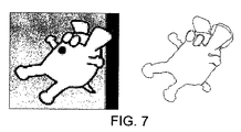
2次元トレースをプロットするためには、反射体の移動の概要をプロットできるようにするために、楕円の交差を用いて2つのダイアグラムが連続的に合成される。図7は、指の追跡に使用される画像の例と、上述の装置によって結果的に得られたプロットとを示す。反射体の非常に小さな移動も明確に解像されていることが観察されるであろう。例えば、右側のプロットは、事実上、左側の輪郭におけるいくつかの連続したトレーシングで構成されることもわかる。 To plot a two-dimensional trace, two diagrams are synthesized sequentially using elliptical intersections so that an overview of reflector movement can be plotted. FIG. 7 shows an example of an image used for finger tracking and the resulting plot with the device described above. It will be observed that very small movements of the reflector are also clearly resolved. For example, it can also be seen that the right plot is effectively composed of several consecutive tracings on the left contour.
Claims (43)
インパルス信号を送信することと、
上記オブジェクトからの上記インパルス信号の反射信号を記録することと、
上記インパルス信号を表す行列の一般化された逆行列として計算された逆行列を上記反射信号へ適用して、推定されたチャンネル応答を取得することと、
上記推定されたチャンネル応答に基づいて時間に対する変位の位置ダイアグラムを構築することと、
異なる送信機及び受信機からなる複数のペアからの複数の推定されたチャンネル応答を楕円又は楕円面の交差を用いて合成し、これにより、追跡されている上記オブジェクトの位置を決定することとを含む方法。 A method of tracking an object,
Sending an impulse signal;
Recording the reflected signal of the impulse signal from the object;
Applying an inverse matrix calculated as a generalized inverse of the matrix representing the impulse signal to the reflected signal to obtain an estimated channel response;
Constructing a position diagram of displacement against time based on the estimated channel response ;
Combining multiple estimated channel responses from multiple pairs of different transmitters and receivers using an ellipse or ellipsoidal intersection, thereby determining the position of the object being tracked ; Including methods.
上記方法は、上記一対の行列に、上記受信信号のサンプルを含むベクトルを乗算するステップを含む、請求項1〜16のうちのいずれか1つに記載の方法。 The computed inverse matrix includes a pair of matrices derived from a subset of singular value decompositions of the matrix representing the impulse signal,
17. The method according to any one of claims 1 to 16, wherein the method comprises multiplying the pair of matrices by a vector that includes samples of the received signal.
上記処理手段は、上記送信手段によって送信されるインパルス信号を表す行列の一般化された逆行列として計算された逆行列を、上記受信手段によって受信された信号へ適用して、推定されたチャンネル応答を取得するように構成され、
上記追跡装置は、
上記推定されたチャンネル応答に基づいて時間に対する変位の位置ダイアグラムを構築する手段と、
異なる送信機及び受信機からなる複数のペアからの複数の推定されたチャンネル応答を楕円又は楕円面の交差を用いて合成し、これにより、追跡されている上記オブジェクトの位置を決定する手段とをさらに備える追跡装置。 A tracking device comprising a transmitting means, a receiving means, and a processing means,
The processing means applies an inverse matrix calculated as a generalized inverse matrix of the matrix representing the impulse signal transmitted by the transmitting means to the signal received by the receiving means to estimate the channel response Is configured to get
The tracking device is
Means for constructing a position diagram of displacement with respect to time based on the estimated channel response ;
Combining a plurality of estimated channel responses from a plurality of pairs of different transmitters and receivers using ellipses or ellipsoidal intersections, thereby determining the position of the object being tracked ; A tracking device further provided.
Applications Claiming Priority (3)
| Application Number | Priority Date | Filing Date | Title |
|---|---|---|---|
| US63743704P | 2004-12-21 | 2004-12-21 | |
| US60/637,437 | 2004-12-21 | ||
| PCT/GB2005/004968 WO2006067436A1 (en) | 2004-12-21 | 2005-12-21 | Channel impulse response estimation |
Publications (3)
| Publication Number | Publication Date |
|---|---|
| JP2008524623A JP2008524623A (en) | 2008-07-10 |
| JP2008524623A5 JP2008524623A5 (en) | 2009-02-12 |
| JP5539620B2 true JP5539620B2 (en) | 2014-07-02 |
Family
ID=35954017
Family Applications (1)
| Application Number | Title | Priority Date | Filing Date |
|---|---|---|---|
| JP2007547637A Active JP5539620B2 (en) | 2004-12-21 | 2005-12-21 | Method and apparatus for tracking an object |
Country Status (4)
| Country | Link |
|---|---|
| US (4) | US7768876B2 (en) |
| EP (2) | EP2330783B1 (en) |
| JP (1) | JP5539620B2 (en) |
| WO (1) | WO2006067436A1 (en) |
Families Citing this family (98)
| Publication number | Priority date | Publication date | Assignee | Title |
|---|---|---|---|---|
| EP2330783B1 (en) | 2004-12-21 | 2012-10-10 | Elliptic Laboratories AS | Channel impulse response estimation |
| US20080144441A1 (en) * | 2006-07-11 | 2008-06-19 | Colangelo Frank G | Sonar device |
| EP2701042B1 (en) | 2008-03-18 | 2015-01-28 | Elliptic Laboratories AS | Object and movement detection |
| GB0806196D0 (en) | 2008-04-04 | 2008-05-14 | Elliptic Laboratories As | Multi-range object location estimation |
| TWI475847B (en) * | 2008-04-16 | 2015-03-01 | Koninkl Philips Electronics Nv | Passive radar for presence and motion detection |
| GB0810179D0 (en) * | 2008-06-04 | 2008-07-09 | Elliptic Laboratories As | Object location |
| GB0816222D0 (en) * | 2008-09-05 | 2008-10-15 | Elliptic Laboratories As | Machine interfaces |
| WO2017100706A1 (en) | 2015-12-09 | 2017-06-15 | Origin Wireless, Inc. | Method, apparatus, and systems for wireless event detection and monitoring |
| US10447094B2 (en) | 2016-05-03 | 2019-10-15 | Origin Wireless, Inc. | Method, system, and apparatus for wireless power transmission based on power waveforming |
| US9559874B2 (en) | 2013-08-16 | 2017-01-31 | Origin Wireless, Inc. | Multiuser time-reversal division multiple access uplink system with parallel interference cancellation |
| US10129862B1 (en) | 2016-02-16 | 2018-11-13 | Origin Wireless, Inc. | Methods, devices, apparatus, and systems for medium access control in wireless communication systems utilizing spatial focusing effect |
| US10291460B2 (en) | 2012-12-05 | 2019-05-14 | Origin Wireless, Inc. | Method, apparatus, and system for wireless motion monitoring |
| US9407306B2 (en) | 2014-04-25 | 2016-08-02 | Origin Wireless, Inc. | Quadrature amplitude modulation for time-reversal systems |
| US10609711B1 (en) | 2015-03-05 | 2020-03-31 | Origin Wireless, Inc. | Time-reversal scalability for high network densification |
| US11025475B2 (en) | 2012-12-05 | 2021-06-01 | Origin Wireless, Inc. | Method, apparatus, server, and systems of time-reversal technology |
| US9686054B2 (en) | 2014-07-17 | 2017-06-20 | Origin Wireless, Inc. | Joint waveform design and interference pre-cancellation for time-reversal systems |
| US9882675B2 (en) | 2013-08-16 | 2018-01-30 | Origin Wireless, Inc. | Time-reversal wireless systems having asymmetric architecture |
| US10014982B1 (en) | 2015-01-22 | 2018-07-03 | Origin Wireless, Inc. | Time-reversal technologies for hybrid wireless networks |
| US9883511B1 (en) | 2012-12-05 | 2018-01-30 | Origin Wireless, Inc. | Waveform design for time-reversal systems |
| US9226304B2 (en) | 2014-03-10 | 2015-12-29 | Origin Wireless, Inc. | Time-reversal wireless paradigm for internet of things |
| US10168414B2 (en) | 2014-07-17 | 2019-01-01 | Origin Wireless, Inc. | Wireless signals and techniques for determining locations of objects in multi-path environments |
| US9887864B1 (en) | 2014-03-10 | 2018-02-06 | Origin Wireless, Inc. | Methods, devices and systems of heterogeneous time-reversal paradigm enabling direct connectivity in internet of things |
| US10440705B2 (en) | 2012-12-05 | 2019-10-08 | Origin Wireless, Inc. | Method, apparatus, server, and systems of time-reversal technology |
| WO2010042319A2 (en) | 2008-10-10 | 2010-04-15 | Ziva Corporation | Techniques and systems for wireless communications |
| EP2474102A4 (en) | 2009-09-03 | 2016-06-22 | Ziva Corp | Techniques and systems for communications based on time reversal pre-coding |
| GB0916707D0 (en) * | 2009-09-23 | 2009-11-04 | Elliptic Laboratories As | Acoustic motion determination |
| US9329728B2 (en) | 2009-10-07 | 2016-05-03 | Elliptic Laboratories As | User interfaces |
| US8644402B2 (en) * | 2009-11-24 | 2014-02-04 | Qualcomm, Incorporated | Apparatus and method for compressive sensing tap identification for channel estimation |
| US8665971B2 (en) | 2009-11-24 | 2014-03-04 | Qualcomm, Incorporated | Apparatus and method for channel estimation using compressive sensing |
| US8582674B2 (en) | 2009-11-24 | 2013-11-12 | Qualcomm Incorporated | Apparatus and method for channel estimation using compressive sensing based on Taylor series expansion |
| US8907929B2 (en) | 2010-06-29 | 2014-12-09 | Qualcomm Incorporated | Touchless sensing and gesture recognition using continuous wave ultrasound signals |
| US9983679B2 (en) | 2010-08-19 | 2018-05-29 | Elliptic Laboratories As | Interaction with portable devices |
| WO2012028884A1 (en) | 2010-09-02 | 2012-03-08 | Elliptic Laboratories As | Motion feedback |
| US8223589B2 (en) * | 2010-10-28 | 2012-07-17 | Hon Hai Precision Industry Co., Ltd. | Gesture recognition apparatus and method |
| WO2012066541A2 (en) * | 2010-11-16 | 2012-05-24 | Epos Development Ltd. | System and method for object position estimation based on ultrasonic reflected signals |
| GB201021477D0 (en) * | 2010-12-17 | 2011-02-02 | Elliptic Laboratories As | Signal processing |
| US9857868B2 (en) | 2011-03-19 | 2018-01-02 | The Board Of Trustees Of The Leland Stanford Junior University | Method and system for ergonomic touch-free interface |
| US8840466B2 (en) | 2011-04-25 | 2014-09-23 | Aquifi, Inc. | Method and system to create three-dimensional mapping in a two-dimensional game |
| GB201116734D0 (en) | 2011-09-28 | 2011-11-09 | Elliptic Laboratories As | Improvements in touchless object motion estimation |
| US9084058B2 (en) | 2011-12-29 | 2015-07-14 | Sonos, Inc. | Sound field calibration using listener localization |
| US8854433B1 (en) | 2012-02-03 | 2014-10-07 | Aquifi, Inc. | Method and system enabling natural user interface gestures with an electronic system |
| GB201203832D0 (en) | 2012-03-05 | 2012-04-18 | Elliptic Laboratories As | User input system |
| WO2013140130A1 (en) | 2012-03-21 | 2013-09-26 | Elliptic Laboratories As | Signal processing for acoustic user input |
| US9111135B2 (en) | 2012-06-25 | 2015-08-18 | Aquifi, Inc. | Systems and methods for tracking human hands using parts based template matching using corresponding pixels in bounded regions of a sequence of frames that are a specified distance interval from a reference camera |
| US8934675B2 (en) | 2012-06-25 | 2015-01-13 | Aquifi, Inc. | Systems and methods for tracking human hands by performing parts based template matching using images from multiple viewpoints |
| US9219460B2 (en) | 2014-03-17 | 2015-12-22 | Sonos, Inc. | Audio settings based on environment |
| US9690539B2 (en) | 2012-06-28 | 2017-06-27 | Sonos, Inc. | Speaker calibration user interface |
| US9106192B2 (en) | 2012-06-28 | 2015-08-11 | Sonos, Inc. | System and method for device playback calibration |
| US9706323B2 (en) | 2014-09-09 | 2017-07-11 | Sonos, Inc. | Playback device calibration |
| GB2503760A (en) * | 2012-07-02 | 2014-01-08 | Koninkl Philips Electronics Nv | A Method for Processing Scanner Signals from an Ultrasound Transducer |
| GB201212685D0 (en) | 2012-07-17 | 2012-08-29 | Elliptic Laboratories As | Control of electronic devices |
| US8836768B1 (en) | 2012-09-04 | 2014-09-16 | Aquifi, Inc. | Method and system enabling natural user interface gestures with user wearable glasses |
| US10270642B2 (en) | 2012-12-05 | 2019-04-23 | Origin Wireless, Inc. | Method, apparatus, and system for object tracking and navigation |
| US10122409B2 (en) | 2012-12-03 | 2018-11-06 | University Of Maryland At College Park | Systems and methods for time-reversal division multiple access wireless broadband communications |
| US9313020B2 (en) | 2014-02-19 | 2016-04-12 | Origin Wireless, Inc. | Handshaking protocol for time-reversal system |
| US10327213B1 (en) | 2015-10-01 | 2019-06-18 | Origin Wireless, Inc. | Time-reversal communication systems |
| US9129155B2 (en) | 2013-01-30 | 2015-09-08 | Aquifi, Inc. | Systems and methods for initializing motion tracking of human hands using template matching within bounded regions determined using a depth map |
| US9092665B2 (en) | 2013-01-30 | 2015-07-28 | Aquifi, Inc | Systems and methods for initializing motion tracking of human hands |
| KR101438114B1 (en) | 2013-02-01 | 2014-11-03 | 국방과학연구소 | Method for Active Sonar Underwater Target Classification Using Canonical Correlation Analysis and Underwater Target Classification Apparatus |
| US9298266B2 (en) | 2013-04-02 | 2016-03-29 | Aquifi, Inc. | Systems and methods for implementing three-dimensional (3D) gesture based graphical user interfaces (GUI) that incorporate gesture reactive interface objects |
| US9817565B2 (en) | 2013-07-23 | 2017-11-14 | Blackberry Limited | Apparatus and method pertaining to the use of a plurality of 3D gesture sensors to detect 3D gestures |
| US9798388B1 (en) | 2013-07-31 | 2017-10-24 | Aquifi, Inc. | Vibrotactile system to augment 3D input systems |
| US9507417B2 (en) | 2014-01-07 | 2016-11-29 | Aquifi, Inc. | Systems and methods for implementing head tracking based graphical user interfaces (GUI) that incorporate gesture reactive interface objects |
| US9619105B1 (en) | 2014-01-30 | 2017-04-11 | Aquifi, Inc. | Systems and methods for gesture based interaction with viewpoint dependent user interfaces |
| US9264839B2 (en) | 2014-03-17 | 2016-02-16 | Sonos, Inc. | Playback device configuration based on proximity detection |
| US9614658B2 (en) * | 2014-06-20 | 2017-04-04 | Huawei Technologies Co., Ltd. | System and method for radio full duplex |
| US9705662B2 (en) | 2014-08-15 | 2017-07-11 | Huawei Technologies Co., Ltd. | System and method for radio full duplex |
| US9952825B2 (en) | 2014-09-09 | 2018-04-24 | Sonos, Inc. | Audio processing algorithms |
| US9891881B2 (en) | 2014-09-09 | 2018-02-13 | Sonos, Inc. | Audio processing algorithm database |
| US10127006B2 (en) | 2014-09-09 | 2018-11-13 | Sonos, Inc. | Facilitating calibration of an audio playback device |
| US9910634B2 (en) | 2014-09-09 | 2018-03-06 | Sonos, Inc. | Microphone calibration |
| GB201421427D0 (en) | 2014-12-02 | 2015-01-14 | Elliptic Laboratories As | Ultrasonic proximity and movement detection |
| WO2016172593A1 (en) | 2015-04-24 | 2016-10-27 | Sonos, Inc. | Playback device calibration user interfaces |
| US10664224B2 (en) | 2015-04-24 | 2020-05-26 | Sonos, Inc. | Speaker calibration user interface |
| US9538305B2 (en) | 2015-07-28 | 2017-01-03 | Sonos, Inc. | Calibration error conditions |
| EP3531714B1 (en) | 2015-09-17 | 2022-02-23 | Sonos Inc. | Facilitating calibration of an audio playback device |
| US9693165B2 (en) | 2015-09-17 | 2017-06-27 | Sonos, Inc. | Validation of audio calibration using multi-dimensional motion check |
| US9743207B1 (en) | 2016-01-18 | 2017-08-22 | Sonos, Inc. | Calibration using multiple recording devices |
| US10003899B2 (en) | 2016-01-25 | 2018-06-19 | Sonos, Inc. | Calibration with particular locations |
| US11106423B2 (en) | 2016-01-25 | 2021-08-31 | Sonos, Inc. | Evaluating calibration of a playback device |
| GB201602319D0 (en) | 2016-02-09 | 2016-03-23 | Elliptic Laboratories As | Proximity detection |
| US9860662B2 (en) | 2016-04-01 | 2018-01-02 | Sonos, Inc. | Updating playback device configuration information based on calibration data |
| US9864574B2 (en) | 2016-04-01 | 2018-01-09 | Sonos, Inc. | Playback device calibration based on representation spectral characteristics |
| US9763018B1 (en) * | 2016-04-12 | 2017-09-12 | Sonos, Inc. | Calibration of audio playback devices |
| US9794710B1 (en) | 2016-07-15 | 2017-10-17 | Sonos, Inc. | Spatial audio correction |
| US9860670B1 (en) | 2016-07-15 | 2018-01-02 | Sonos, Inc. | Spectral correction using spatial calibration |
| US10372406B2 (en) | 2016-07-22 | 2019-08-06 | Sonos, Inc. | Calibration interface |
| US10459684B2 (en) | 2016-08-05 | 2019-10-29 | Sonos, Inc. | Calibration of a playback device based on an estimated frequency response |
| CN106897558A (en) * | 2017-02-24 | 2017-06-27 | 王雯钰 | A kind of Chinese medicine nursing percussion device for rehabilitation control system |
| US11307324B2 (en) | 2018-03-21 | 2022-04-19 | Massachusetts Institute Of Technology | Systems and methods for detecting seismo-electromagnetic conversion |
| WO2019217653A1 (en) * | 2018-05-09 | 2019-11-14 | Massachusetts Institute Of Technology | Systems and methods for focused blind deconvolution |
| US10299061B1 (en) | 2018-08-28 | 2019-05-21 | Sonos, Inc. | Playback device calibration |
| US11206484B2 (en) | 2018-08-28 | 2021-12-21 | Sonos, Inc. | Passive speaker authentication |
| US11165462B2 (en) * | 2018-11-07 | 2021-11-02 | Samsung Electronics Co., Ltd. | Motion assisted leakage removal for radar applications |
| US11085293B2 (en) | 2019-06-06 | 2021-08-10 | Massachusetts Institute Of Technology | Sequential estimation while drilling |
| US10734965B1 (en) | 2019-08-12 | 2020-08-04 | Sonos, Inc. | Audio calibration of a portable playback device |
| KR102639501B1 (en) * | 2020-04-16 | 2024-02-23 | 삼성전자주식회사 | Electronic device performing extension of bandwidth for sensing by integrating channel impulse responses and method for controlling thereof |
| WO2023239205A1 (en) * | 2022-06-10 | 2023-12-14 | Samsung Electronics Co., Ltd. | Method and device for inference in ultra-wide band system (uwb) |
Family Cites Families (20)
| Publication number | Priority date | Publication date | Assignee | Title |
|---|---|---|---|---|
| JPS58166278A (en) * | 1982-03-26 | 1983-10-01 | Koden Electronics Co Ltd | Separating method of time series signal |
| US4506354A (en) * | 1982-09-30 | 1985-03-19 | Position Orientation Systems, Ltd. | Ultrasonic position detecting system |
| US5059959A (en) * | 1985-06-03 | 1991-10-22 | Seven Oaks Corporation | Cursor positioning method and apparatus |
| JPH04100381A (en) * | 1990-08-20 | 1992-04-02 | Hitachi Ltd | Waveform equalizer for tv receiver |
| US6265676B1 (en) * | 1997-03-10 | 2001-07-24 | Electronics For Imaging, Inc. | Systems and processing algorithms for ultrasound time-of-flight digitizer systems |
| US6130663A (en) * | 1997-07-31 | 2000-10-10 | Null; Nathan D. | Touchless input method and apparatus |
| US6950534B2 (en) * | 1998-08-10 | 2005-09-27 | Cybernet Systems Corporation | Gesture-controlled interfaces for self-service machines and other applications |
| US6198470B1 (en) | 1998-12-28 | 2001-03-06 | Uri Agam | Computer input device |
| US6313825B1 (en) * | 1998-12-28 | 2001-11-06 | Gateway, Inc. | Virtual input device |
| US6799141B1 (en) * | 1999-06-09 | 2004-09-28 | Beamcontrol Aps | Method for determining the channel gain between emitters and receivers |
| US20020140633A1 (en) | 2000-02-03 | 2002-10-03 | Canesta, Inc. | Method and system to present immersion virtual simulations using three-dimensional measurement |
| AU2001251344A1 (en) | 2000-04-05 | 2001-10-23 | Dimensional Media Associates, Inc. | Methods and apparatus for virtual touchscreen computer interface controller |
| JP2002008004A (en) * | 2000-06-20 | 2002-01-11 | Japan Radio Co Ltd | Deconvolution processing device |
| JP2005043164A (en) | 2003-07-25 | 2005-02-17 | Toshiba Corp | Apparatus for measuring propagation time of sound wave |
| EP2330783B1 (en) * | 2004-12-21 | 2012-10-10 | Elliptic Laboratories AS | Channel impulse response estimation |
| US20070085828A1 (en) * | 2005-10-13 | 2007-04-19 | Schroeder Dale W | Ultrasonic virtual mouse |
| GB0806196D0 (en) * | 2008-04-04 | 2008-05-14 | Elliptic Laboratories As | Multi-range object location estimation |
| US9066191B2 (en) * | 2008-04-09 | 2015-06-23 | Fraunhofer-Gesellschaft Zur Foerderung Der Angewandten Forschung E.V. | Apparatus and method for generating filter characteristics |
| GB0810179D0 (en) * | 2008-06-04 | 2008-07-09 | Elliptic Laboratories As | Object location |
| US8907929B2 (en) * | 2010-06-29 | 2014-12-09 | Qualcomm Incorporated | Touchless sensing and gesture recognition using continuous wave ultrasound signals |
-
2005
- 2005-12-21 EP EP11155623A patent/EP2330783B1/en active Active
- 2005-12-21 WO PCT/GB2005/004968 patent/WO2006067436A1/en active Application Filing
- 2005-12-21 EP EP05821006A patent/EP1851924B1/en active Active
- 2005-12-21 JP JP2007547637A patent/JP5539620B2/en active Active
-
2007
- 2007-06-21 US US11/766,651 patent/US7768876B2/en active Active
-
2010
- 2010-08-02 US US12/848,930 patent/US8072842B2/en active Active
-
2011
- 2011-10-26 US US13/282,382 patent/US8305843B2/en active Active
-
2012
- 2012-10-05 US US13/646,440 patent/US8531916B2/en active Active
Also Published As
| Publication number | Publication date |
|---|---|
| US20080281523A1 (en) | 2008-11-13 |
| US20120099403A1 (en) | 2012-04-26 |
| US8072842B2 (en) | 2011-12-06 |
| US7768876B2 (en) | 2010-08-03 |
| EP2330783B1 (en) | 2012-10-10 |
| JP2008524623A (en) | 2008-07-10 |
| US8531916B2 (en) | 2013-09-10 |
| EP1851924A1 (en) | 2007-11-07 |
| EP2330783A1 (en) | 2011-06-08 |
| US20130094329A1 (en) | 2013-04-18 |
| EP1851924B1 (en) | 2012-12-05 |
| US8305843B2 (en) | 2012-11-06 |
| WO2006067436A1 (en) | 2006-06-29 |
| US20100296368A1 (en) | 2010-11-25 |
Similar Documents
| Publication | Publication Date | Title |
|---|---|---|
| JP5539620B2 (en) | Method and apparatus for tracking an object | |
| US6719696B2 (en) | High resolution 3D ultrasound imaging system deploying a multi-dimensional array of sensors and method for multi-dimensional beamforming sensor signals | |
| JP5624976B2 (en) | Estimating the position of objects in various ranges | |
| US7460605B2 (en) | Time reversal communication system | |
| US9465101B2 (en) | Aberration correction with broad transmit beams in medical ultrasound | |
| Synnevag et al. | Adaptive beamforming applied to medical ultrasound imaging | |
| US8744155B2 (en) | Imaging or communications system utilizing multisample apodization and method | |
| CN104414687A (en) | Ultrasonic measurement apparatus, ultrasonic imaging apparatus, and ultrasonic measurement method | |
| JP7235534B6 (en) | Microphone array position estimation device, microphone array position estimation method, and program | |
| CN107661120A (en) | Picture is moved into using multiple parallel reception wave beams | |
| WO2003093862A1 (en) | Ultrasound imaging system with a high lateral resolution | |
| CN110536647B (en) | Systems, methods, and computer-readable media for processing and compositing ultrasound images in the presence of motion | |
| EP3088912A1 (en) | Ultrasound imaging system and method for representing rf signals therein | |
| CN112784412B (en) | Single hydrophone normal wave modal separation method and system based on compressed sensing | |
| KR20200000909A (en) | Apparatus and method for suppressing reverberation signal | |
| KR20230156044A (en) | Imaging objects within structures | |
| Amerineni | Multi Channel Sub Band Wiener Beamformer | |
| Northardt | The Higher Order Ambiguity Function Used For Non-Linear Sensor Array Fault Resiliency In The Presence Of Multiple Sources | |
| Ouahabi et al. | Discrete time-frequency (time-scale) techniques for time delay and Doppler estimation |
Legal Events
| Date | Code | Title | Description |
|---|---|---|---|
| A521 | Request for written amendment filed |
Free format text: JAPANESE INTERMEDIATE CODE: A523 Effective date: 20081218 |
|
| A621 | Written request for application examination |
Free format text: JAPANESE INTERMEDIATE CODE: A621 Effective date: 20081218 |
|
| A977 | Report on retrieval |
Free format text: JAPANESE INTERMEDIATE CODE: A971007 Effective date: 20110525 |
|
| A131 | Notification of reasons for refusal |
Free format text: JAPANESE INTERMEDIATE CODE: A131 Effective date: 20110531 |
|
| A711 | Notification of change in applicant |
Free format text: JAPANESE INTERMEDIATE CODE: A711 Effective date: 20110616 |
|
| A521 | Request for written amendment filed |
Free format text: JAPANESE INTERMEDIATE CODE: A821 Effective date: 20110616 |
|
| A601 | Written request for extension of time |
Free format text: JAPANESE INTERMEDIATE CODE: A601 Effective date: 20110826 |
|
| A602 | Written permission of extension of time |
Free format text: JAPANESE INTERMEDIATE CODE: A602 Effective date: 20110902 |
|
| A601 | Written request for extension of time |
Free format text: JAPANESE INTERMEDIATE CODE: A601 Effective date: 20110928 |
|
| A602 | Written permission of extension of time |
Free format text: JAPANESE INTERMEDIATE CODE: A602 Effective date: 20111005 |
|
| A601 | Written request for extension of time |
Free format text: JAPANESE INTERMEDIATE CODE: A601 Effective date: 20111026 |
|
| A602 | Written permission of extension of time |
Free format text: JAPANESE INTERMEDIATE CODE: A602 Effective date: 20111102 |
|
| A521 | Request for written amendment filed |
Free format text: JAPANESE INTERMEDIATE CODE: A523 Effective date: 20111108 |
|
| A131 | Notification of reasons for refusal |
Free format text: JAPANESE INTERMEDIATE CODE: A131 Effective date: 20120214 |
|
| A601 | Written request for extension of time |
Free format text: JAPANESE INTERMEDIATE CODE: A601 Effective date: 20120514 |
|
| A602 | Written permission of extension of time |
Free format text: JAPANESE INTERMEDIATE CODE: A602 Effective date: 20120521 |
|
| A521 | Request for written amendment filed |
Free format text: JAPANESE INTERMEDIATE CODE: A523 Effective date: 20120606 |
|
| A131 | Notification of reasons for refusal |
Free format text: JAPANESE INTERMEDIATE CODE: A131 Effective date: 20130319 |
|
| A601 | Written request for extension of time |
Free format text: JAPANESE INTERMEDIATE CODE: A601 Effective date: 20130618 |
|
| A602 | Written permission of extension of time |
Free format text: JAPANESE INTERMEDIATE CODE: A602 Effective date: 20130625 |
|
| A521 | Request for written amendment filed |
Free format text: JAPANESE INTERMEDIATE CODE: A523 Effective date: 20130718 |
|
| TRDD | Decision of grant or rejection written | ||
| A01 | Written decision to grant a patent or to grant a registration (utility model) |
Free format text: JAPANESE INTERMEDIATE CODE: A01 Effective date: 20140415 |
|
| R150 | Certificate of patent or registration of utility model |
Ref document number: 5539620 Country of ref document: JP Free format text: JAPANESE INTERMEDIATE CODE: R150 |
|
| A61 | First payment of annual fees (during grant procedure) |
Free format text: JAPANESE INTERMEDIATE CODE: A61 Effective date: 20140501 |
|
| R250 | Receipt of annual fees |
Free format text: JAPANESE INTERMEDIATE CODE: R250 |
|
| R250 | Receipt of annual fees |
Free format text: JAPANESE INTERMEDIATE CODE: R250 |
|
| R250 | Receipt of annual fees |
Free format text: JAPANESE INTERMEDIATE CODE: R250 |
|
| R250 | Receipt of annual fees |
Free format text: JAPANESE INTERMEDIATE CODE: R250 |
|
| R250 | Receipt of annual fees |
Free format text: JAPANESE INTERMEDIATE CODE: R250 |
|
| R250 | Receipt of annual fees |
Free format text: JAPANESE INTERMEDIATE CODE: R250 |
|
| R250 | Receipt of annual fees |
Free format text: JAPANESE INTERMEDIATE CODE: R250 |
|
| R250 | Receipt of annual fees |
Free format text: JAPANESE INTERMEDIATE CODE: R250 |