JP5538694B2 - Radiation imaging apparatus and control method thereof - Google Patents
Radiation imaging apparatus and control method thereof Download PDFInfo
- Publication number
- JP5538694B2 JP5538694B2 JP2008220500A JP2008220500A JP5538694B2 JP 5538694 B2 JP5538694 B2 JP 5538694B2 JP 2008220500 A JP2008220500 A JP 2008220500A JP 2008220500 A JP2008220500 A JP 2008220500A JP 5538694 B2 JP5538694 B2 JP 5538694B2
- Authority
- JP
- Japan
- Prior art keywords
- connection
- unit
- detection unit
- radiation
- ray image
- Prior art date
- Legal status (The legal status is an assumption and is not a legal conclusion. Google has not performed a legal analysis and makes no representation as to the accuracy of the status listed.)
- Active
Links
- 238000003384 imaging method Methods 0.000 title claims description 68
- 230000005855 radiation Effects 0.000 title claims description 45
- 238000000034 method Methods 0.000 title claims description 32
- 238000001514 detection method Methods 0.000 claims description 122
- 238000004891 communication Methods 0.000 claims description 26
- 230000006870 function Effects 0.000 description 16
- 238000012545 processing Methods 0.000 description 14
- 238000010586 diagram Methods 0.000 description 8
- OAICVXFJPJFONN-UHFFFAOYSA-N Phosphorus Chemical compound [P] OAICVXFJPJFONN-UHFFFAOYSA-N 0.000 description 6
- 238000006243 chemical reaction Methods 0.000 description 6
- 239000004065 semiconductor Substances 0.000 description 5
- 238000012546 transfer Methods 0.000 description 5
- 238000004590 computer program Methods 0.000 description 4
- 230000020169 heat generation Effects 0.000 description 4
- 230000036544 posture Effects 0.000 description 4
- 230000008569 process Effects 0.000 description 4
- 239000000758 substrate Substances 0.000 description 4
- 230000008901 benefit Effects 0.000 description 3
- 229910052751 metal Inorganic materials 0.000 description 3
- 239000002184 metal Substances 0.000 description 3
- 230000003287 optical effect Effects 0.000 description 3
- 230000005540 biological transmission Effects 0.000 description 2
- 238000001816 cooling Methods 0.000 description 2
- 238000005516 engineering process Methods 0.000 description 2
- 239000011521 glass Substances 0.000 description 2
- 230000001678 irradiating effect Effects 0.000 description 2
- 230000007246 mechanism Effects 0.000 description 2
- 238000002601 radiography Methods 0.000 description 2
- 239000000126 substance Substances 0.000 description 2
- 238000009825 accumulation Methods 0.000 description 1
- 230000009471 action Effects 0.000 description 1
- 238000012993 chemical processing Methods 0.000 description 1
- 239000000470 constituent Substances 0.000 description 1
- 238000012937 correction Methods 0.000 description 1
- 238000003745 diagnosis Methods 0.000 description 1
- 238000007599 discharging Methods 0.000 description 1
- 230000000694 effects Effects 0.000 description 1
- 230000005284 excitation Effects 0.000 description 1
- 230000017525 heat dissipation Effects 0.000 description 1
- 238000003702 image correction Methods 0.000 description 1
- 238000003780 insertion Methods 0.000 description 1
- 230000037431 insertion Effects 0.000 description 1
- 238000007689 inspection Methods 0.000 description 1
- 238000009434 installation Methods 0.000 description 1
- 239000000463 material Substances 0.000 description 1
- 150000002736 metal compounds Chemical class 0.000 description 1
- 238000012986 modification Methods 0.000 description 1
- 230000004048 modification Effects 0.000 description 1
- 238000012544 monitoring process Methods 0.000 description 1
- 230000035699 permeability Effects 0.000 description 1
- 229910052761 rare earth metal Inorganic materials 0.000 description 1
- 150000002910 rare earth metals Chemical class 0.000 description 1
- 239000011347 resin Substances 0.000 description 1
- 229920005989 resin Polymers 0.000 description 1
- 230000035945 sensitivity Effects 0.000 description 1
- 238000004381 surface treatment Methods 0.000 description 1
- 238000009423 ventilation Methods 0.000 description 1
Images


Classifications
-
- A—HUMAN NECESSITIES
- A61—MEDICAL OR VETERINARY SCIENCE; HYGIENE
- A61B—DIAGNOSIS; SURGERY; IDENTIFICATION
- A61B6/00—Apparatus or devices for radiation diagnosis; Apparatus or devices for radiation diagnosis combined with radiation therapy equipment
-
- A—HUMAN NECESSITIES
- A61—MEDICAL OR VETERINARY SCIENCE; HYGIENE
- A61B—DIAGNOSIS; SURGERY; IDENTIFICATION
- A61B6/00—Apparatus or devices for radiation diagnosis; Apparatus or devices for radiation diagnosis combined with radiation therapy equipment
- A61B6/42—Arrangements for detecting radiation specially adapted for radiation diagnosis
- A61B6/4208—Arrangements for detecting radiation specially adapted for radiation diagnosis characterised by using a particular type of detector
- A61B6/4233—Arrangements for detecting radiation specially adapted for radiation diagnosis characterised by using a particular type of detector using matrix detectors
-
- A—HUMAN NECESSITIES
- A61—MEDICAL OR VETERINARY SCIENCE; HYGIENE
- A61B—DIAGNOSIS; SURGERY; IDENTIFICATION
- A61B6/00—Apparatus or devices for radiation diagnosis; Apparatus or devices for radiation diagnosis combined with radiation therapy equipment
- A61B6/44—Constructional features of apparatus for radiation diagnosis
- A61B6/4488—Means for cooling
-
- A—HUMAN NECESSITIES
- A61—MEDICAL OR VETERINARY SCIENCE; HYGIENE
- A61B—DIAGNOSIS; SURGERY; IDENTIFICATION
- A61B6/00—Apparatus or devices for radiation diagnosis; Apparatus or devices for radiation diagnosis combined with radiation therapy equipment
- A61B6/44—Constructional features of apparatus for radiation diagnosis
- A61B6/4494—Means for identifying the diagnostic device
-
- A—HUMAN NECESSITIES
- A61—MEDICAL OR VETERINARY SCIENCE; HYGIENE
- A61B—DIAGNOSIS; SURGERY; IDENTIFICATION
- A61B6/00—Apparatus or devices for radiation diagnosis; Apparatus or devices for radiation diagnosis combined with radiation therapy equipment
- A61B6/56—Details of data transmission or power supply, e.g. use of slip rings
- A61B6/563—Details of data transmission or power supply, e.g. use of slip rings involving image data transmission via a network
-
- A—HUMAN NECESSITIES
- A61—MEDICAL OR VETERINARY SCIENCE; HYGIENE
- A61B—DIAGNOSIS; SURGERY; IDENTIFICATION
- A61B6/00—Apparatus or devices for radiation diagnosis; Apparatus or devices for radiation diagnosis combined with radiation therapy equipment
- A61B6/44—Constructional features of apparatus for radiation diagnosis
- A61B6/4405—Constructional features of apparatus for radiation diagnosis the apparatus being movable or portable, e.g. handheld or mounted on a trolley
-
- A—HUMAN NECESSITIES
- A61—MEDICAL OR VETERINARY SCIENCE; HYGIENE
- A61B—DIAGNOSIS; SURGERY; IDENTIFICATION
- A61B6/00—Apparatus or devices for radiation diagnosis; Apparatus or devices for radiation diagnosis combined with radiation therapy equipment
- A61B6/44—Constructional features of apparatus for radiation diagnosis
- A61B6/4429—Constructional features of apparatus for radiation diagnosis related to the mounting of source units and detector units
- A61B6/4435—Constructional features of apparatus for radiation diagnosis related to the mounting of source units and detector units the source unit and the detector unit being coupled by a rigid structure
- A61B6/4441—Constructional features of apparatus for radiation diagnosis related to the mounting of source units and detector units the source unit and the detector unit being coupled by a rigid structure the rigid structure being a C-arm or U-arm
Landscapes
- Health & Medical Sciences (AREA)
- Life Sciences & Earth Sciences (AREA)
- Engineering & Computer Science (AREA)
- Medical Informatics (AREA)
- Physics & Mathematics (AREA)
- Radiology & Medical Imaging (AREA)
- Surgery (AREA)
- Nuclear Medicine, Radiotherapy & Molecular Imaging (AREA)
- Optics & Photonics (AREA)
- Pathology (AREA)
- Biophysics (AREA)
- Biomedical Technology (AREA)
- Heart & Thoracic Surgery (AREA)
- Molecular Biology (AREA)
- High Energy & Nuclear Physics (AREA)
- Animal Behavior & Ethology (AREA)
- General Health & Medical Sciences (AREA)
- Public Health (AREA)
- Veterinary Medicine (AREA)
- Mathematical Physics (AREA)
- Computer Networks & Wireless Communication (AREA)
- Apparatus For Radiation Diagnosis (AREA)
Description
本発明は、放射線を用いて被写体を放射線撮影する放射線画像撮影装置及びその制御方法に関する。 The present invention relates to a radiographic imaging apparatus that radiographs a subject using radiation and a control method thereof.
従来、対象物に放射線を照射し、当該対象物を透過した放射線の強度分布を検出して対象物の放射線画像を得る装置が知られている。このような装置は、工業用の非破壊検査や医療診断の場で広く一般に利用されている。 2. Description of the Related Art Conventionally, there has been known an apparatus that obtains a radiation image of an object by irradiating the object with radiation and detecting an intensity distribution of the radiation transmitted through the object. Such a device is widely used in industrial nondestructive inspection and medical diagnosis.
このような撮影では、一般に、放射線に対するフィルム/スクリーン方法が用いられる。これは感光性フィルムと放射線に対して感度を有している蛍光体とを組合せて撮影する方法である。この方法では、放射線の照射により発光する希土類の蛍光体をシート状にしたものを感光性フィルムの両面に密着して保持し、被写体を透過した放射線を蛍光体で可視光に変換し、感光性フィルムで光を捉える。その後、フィルム上に形成された潜像を化学処理で現像することで可視化する。 In such imaging, a film / screen method for radiation is generally used. This is a method of photographing by combining a photosensitive film and a phosphor having sensitivity to radiation. In this method, a sheet of rare earth phosphor that emits light when irradiated with radiation is held in close contact with both sides of the photosensitive film, and the radiation that has passed through the subject is converted into visible light by the phosphor. Capture light with film. Thereafter, the latent image formed on the film is visualized by developing it by chemical processing.
一方、近年のデジタル技術の進歩により、放射線画像を電気信号に変換し、この電気信号を画像処理した後、可視画像としてCRT等に再生し高画質の放射線画像を得る方式が普及してきている。このような放射線画像を電気信号に変換する方法として、放射線の透過画像を一旦、蛍光体中に潜像として蓄積し、後にレーザー光等の励起光を照射することで潜像を光電的に読み出し、可視像として出力する放射線画像記録再生システムが提案されている。 On the other hand, with the recent advancement of digital technology, a method of converting a radiographic image into an electrical signal, processing the electrical signal, and reproducing it as a visible image on a CRT or the like to obtain a high-quality radiographic image has become widespread. As a method for converting such a radiation image into an electrical signal, a radiation transmission image is temporarily accumulated as a latent image in a phosphor, and then the latent image is photoelectrically read out by irradiating excitation light such as laser light. A radiation image recording / reproducing system that outputs a visible image has been proposed.
また、近年の半導体プロセス技術の進歩に伴い、半導体センサを使用して放射線画像を撮影する装置が知られている。このシステムは、従来の感光性フィルムを用いる放射線写真システムに比べて非常に広いダイナミックレンジを有しており、放射線の露光量の変動に影響されない放射線画像を得ることができる。また、従来の感光性フィルム方式と異なり、化学処理がいらず、即時的に出力画像を得ることができる。 With recent advances in semiconductor process technology, an apparatus for taking a radiation image using a semiconductor sensor is known. This system has a very wide dynamic range as compared with a radiographic system using a conventional photosensitive film, and can obtain a radiographic image that is not affected by fluctuations in the exposure dose of radiation. Further, unlike the conventional photosensitive film system, no chemical treatment is required and an output image can be obtained immediately.
図12は、このような放射線画像撮影装置を用いたシステムを示す概念図である。 FIG. 12 is a conceptual diagram showing a system using such a radiographic imaging apparatus.
103は、放射線検出センサ104を内蔵した放射線画像撮影装置(以下、X線像撮影部と略す)である。放射線発生装置101によって発せられた放射線を被写体102に照射すると、被写体を透過した放射線が蛍光体を介して可視光に変換され、二次元の格子状に配列した光電変換素子によって電気信号として検出される。このシステムには、放射線検出センサ104に対して読出し駆動や画像転送などの制御を行う制御部105が設けられている。制御部105の制御により、X線像撮影部103から出力された画像がデジタル画像処理され、モニタ106に被写体の放射線画像が表示される。
このシステムは、前述の放射線画像記録再生システムとは異なり、即時的に画像をモニタできる点が長所である。このようなシステムでは、一般に、放射線室に固定に据え置かれた専用の架台にX線像撮影部を設置し、立位や臥位などにより撮影することになる。近年では可搬型のX線像撮影部も開発されており、任意の撮影姿勢での撮影も行なえるようになっている。特許文献1には、過般型のX線像撮影部を、管球に対向する位置に固定して支持したり、また、支持部から切り離し単体で用いるようにしたりする技術が提案されている。前者においては位置決めが容易となり、高精度のアライメントを迅速に行なえることになる。後者においてはX線像撮影部を自由な位置に置くことができるため、動けない被験者に対しても利用できるので、被験者の負担を軽減できる。このように特許文献1で提案される技術によれば、1つの装置で2つの撮影形態を実現できるため、利便性を向上させることができる。
しかし、その反面、2つの異なる撮影形態を一つの装置で実現するため、それぞれに最適な装置として考えた場合、配慮しなければならない課題もある。 On the other hand, since two different photographing modes are realized by one apparatus, there is a problem that must be considered when considering each apparatus as an optimum apparatus.
医療現場では装置間の混線やペースメーカ等への影響、また無線の信頼性を懸念して無線化が促進しない傾向にある。前述のX線像撮影部でも実際は、装置に電源を供給したり、情報を授受したりするケーブルが設けられる。テーブル上でカセッテ用途としてX線像撮影部を使用する際には、人体が装置上に乗る場合が少なからずある。そのため、ケーブルは、厚み方向に凹凸を生じないように側面から引き出され、引回しの操作性を考慮して可とう性の高い構造で形成される。これに対して架台に支持されている場合は、装置側面へのケーブル引回しは、人体へのアライメントや操作性上邪魔になる可能性が大きく、ケーブルの可とう性よりも通信の高速性の方が優先度が高い仕様となる。 In the medical field, there is a tendency that wireless communication is not promoted due to concerns about crosstalk between devices, effects on pacemakers, and wireless reliability. In the above-described X-ray imaging unit, a cable for supplying power to the apparatus and exchanging information is actually provided. When using an X-ray imaging unit on a table as a cassette application, a human body often gets on the apparatus. Therefore, the cable is drawn out from the side surface so as not to cause unevenness in the thickness direction, and is formed with a highly flexible structure in consideration of the operability of routing. On the other hand, when supported by the gantry, cable routing to the side of the device is likely to interfere with human alignment and operability, and communication speed is higher than cable flexibility. This is a higher priority specification.
そこで、本発明は、上記問題点に鑑みてなされたものであり、可搬可能に検出部を使用する際の利便性と固定して検出部を使用する際の高機能性とを両立させるようにした放射線画像撮影装置及びその制御方法を提供することを目的とする。 Therefore, the present invention has been made in view of the above-described problems, and it is intended to achieve both convenience when using the detection unit in a portable manner and high functionality when using the detection unit while being fixed. An object of the present invention is to provide a radiographic imaging apparatus and a control method thereof.
上記目的を達成するため、本発明の一態様による放射線画像撮影装置は、被写体に放射線を照射する放射線発生部と、前記被写体を透過した前記放射線発生部からの放射線を検出することにより放射線画像を撮影する検出部と、前記放射線発生部と前記検出部とによる放射線撮影を制御する制御部とを具備し、前記検出部は、可搬可能に使用される場合に前記制御部との接続に使用される第1の接続手段と、支持部により固定して使用される場合に前記制御部との接続に使用される第2の接続手段と、前記第1の接続手段及び前記第2の接続手段のいずれを用いて前記制御部と接続されているかを検知する接続先検知手段と、前記接続先検知手段による検知結果に基づいて前記撮影の動作を決定する決定手段とを具備し、前記決定手段は、前記第1の接続手段により接続されていると検知された場合、前記第2の接続手段により接続される場合よりも前記撮影のフレームレートを低くすることを特徴とする。 In order to achieve the above object, a radiographic imaging device according to an aspect of the present invention includes a radiation generation unit that irradiates a subject with radiation, and a radiation image obtained by detecting radiation from the radiation generation unit that has passed through the subject. A detection unit that performs imaging, and a control unit that controls radiography by the radiation generation unit and the detection unit, and the detection unit is used for connection to the control unit when used in a portable manner First connection means, second connection means used for connection with the control unit when used by being fixed by a support part, the first connection means and the second connection means A connection destination detection means for detecting which of the connection means is connected to, and a determination means for determining the photographing operation based on a detection result by the connection destination detection means. Before When it is detected as being connected by a first connecting means and to lower the frame rate of the imaging than when connected by said second connecting means.
また、本発明の一態様は、
被写体を透過した放射線発生部からの放射線を検出することにより放射線画像を撮影する検出部と、
前記放射線の入射面と直交する前記検出部の側面に設けられ、可搬可能に使用される場合に前記検出部の制御部との接続に使用される第1の接続手段と、
前記放射線の入射面と対向する前記検出部の背面に設けられ、支持部により固定して使用される場合に前記制御部との接続に使用される第2の接続手段と
を備えることを特徴とする。
One embodiment of the present invention includes
A detector for capturing a radiographic image by detecting radiation from the rays generating unit release that transmitted through the Utsushitai,
A first connection means provided on a side surface of the detection unit orthogonal to the incident surface of the radiation and used for connection with the control unit of the detection unit when used in a portable manner;
A second connecting means provided on a back surface of the detection unit facing the radiation incident surface and used for connection to the control unit when used by being fixed by a support unit ;
It is characterized by providing .
本発明によれば、可搬可能に検出部を使用する際の利便性と、固定して検出部を使用する際の高機能性とを両立させることができる。 ADVANTAGE OF THE INVENTION According to this invention, the convenience at the time of using a detection part to be portable and high functionality at the time of using a detection part fixedly can be made compatible.
以下、本発明に係わる放射線画像撮影装置及びその制御方法の一実施の形態について添付図面を参照して詳細に説明する。 Hereinafter, an embodiment of a radiographic imaging apparatus and a control method thereof according to the present invention will be described in detail with reference to the accompanying drawings.
(実施形態1)
図1は、本発明の一実施の形態に係わる放射線画像撮影装置(以下、X線像撮影装置と略す)の機能的な構成の一例を示す図である。
(Embodiment 1)
FIG. 1 is a diagram showing an example of a functional configuration of a radiographic image capturing apparatus (hereinafter abbreviated as an X-ray image capturing apparatus) according to an embodiment of the present invention.
X線像撮影装置80は、1又は複数のコンピュータを含んで構成される。コンピュータには、例えば、CPU等の主制御手段、ROM(Read Only Memory)、RAM(Random Access Memory)等の記憶手段が具備される。また、コンピュータには、ネットワークカード等の通信手段、キーボード、ディスプレイ又はタッチパネル等の入出力手段等、が具備されていてもよい。なお、これら各構成手段は、バス等により接続され、主制御手段が記憶手段に記憶されたプログラムを実行することで制御される。
The X-ray
ここで、X線像撮影装置80は、X線発生部81と、X線像検出部10と、制御部82と、表示部(モニタ)83とを具備して構成される。
Here, the
X線発生部(すなわち、放射線発生部)81は、被写体(例えば、人体)に向けて放射線(X線)を照射する。X線像検出部10は、被写体を透過したX線発生部81からの放射線を検出することにより、当該被写体に基づくX線画像を撮影する。制御部82は、X線像撮影装置80における処理を統括して制御する。例えば、X線発生部81とX線像検出部10とによる(X線撮影)放射線撮影を制御する。この他、例えば、X線像検出部10に対して読出し駆動や画像転送などの制御も行なう。表示部83は、X線像検出部10により撮影された被写体のX線撮影画像を表示する。
An X-ray generation unit (that is, a radiation generation unit) 81 irradiates a subject (for example, a human body) with radiation (X-rays). The X-ray
以上が、X線像撮影装置80における機能的な構成の一例についての説明であるが、この装置内に設けられる機能的な構成は、必ずしも上記図示した通りに実現される必要はない。例えば、上述した各機能構成を、複数の装置にそれぞれ配し、システムとして実現するようにしてもよい。
The above is an explanation of an example of the functional configuration of the
次に、図2〜図4を用いて、図1に示すX線像検出部について説明する。図2は、X線像検出部10の内部断面の一例を示す図であり、図3は、X線像検出部10の外観の斜視図の一例を示す図であり、図4は、X線像検出部10を着脱可能に支持する支持部に装着した場合の一例を示す図である。
Next, the X-ray image detection unit shown in FIG. 1 will be described with reference to FIGS. FIG. 2 is a diagram showing an example of an internal cross section of the X-ray
図2において、1はX線像検出パネルであり、基本的に蛍光板1aと光電変換素子1bと基板1cとで構成される。基板1cは、半導体素子との化学作用のないこと半導体プロセスの温度に耐えること、寸法安定性などの必要性からガラス板が多く用いられる。このようなガラス基板上には、半導体プロセスにより2次元配列的に光電変換素子1bが形成される。蛍光板1aは、金属化合物の蛍光体を樹脂板に塗布したものが用いられ、基板1cと接着によって一体化されている。これらは、X線像検出パネル1として金属製の基台2に固定されている。
In FIG. 2, reference numeral 1 denotes an X-ray image detection panel, which basically comprises a
3は光電変換された電気信号を処理する回路基板であり、フレキシブル回路基板4によって光電変換素子1bと接続されており、基台2の裏側に固定されている。更に、基台2は筐体本体5aに固定され、X線透過性の高い材料から成る筐体蓋5bで密閉されてX線像撮影装置80のX線像検出部10が構成される。このようなX線像検出部10は、X線を照射する管球との組合わせでX線画像の撮影が可能になる。
X線像検出部10では、図2の上側より被写体を透過したX線が入射されると、蛍光板1aが発光し、その光を2次元配列された光電変換素子1bで電気的な信号に変換する。これにより、デジタル画像を得る。デジタル画像は、外部通信部7を介して制御部82に転送される。これにより、利用者は、モニタ上から即時的に撮影画像を見ることができる。
In the X-ray
X線像検出パネル1からの電荷の読み出しは、駆動回路部によって選択された列の複数の光電変換素子1bが蓄積した電荷を、それぞれ行方向に放電させ、各行に対応して設置された読出回路部によって読み取る方式によって行われる。このようなX線像検出部10の駆動時には、各電子部品3、4による電力消費に伴い発熱が生ずる。電気部品から発生した熱は、X線像検出部10内部の温度を上昇させ、筐体5を介して外気に放熱される。X線像検出部10には、画像読み出しに伴った電源供給や信号転送のために、電源供給手段や信号転送手段を有する必要がある。本実施形態においては、X線像検出部10は、外部の制御部82に接続されるため、X線像検出部10の側面、すなわち、放射線入射面と直交した位置に、図2に示すように、2箇所の開口5c、5dが形成される。この開口5c、5dの内部には、ケーブル用の接続端子8、11a及び11bがそれぞれ設けられている。各々の接続端子に対しては、図2の9で図示されるような開閉可能なカバーが設けられている。このようなX線像検出部10は、カセッテとして単独として使用されるか、若しくは種々の支持部と組み合わされて使用される。
The readout of charges from the X-ray image detection panel 1 is performed by discharging the charges accumulated in the plurality of
図3は、X線像検出部10を撮影台20と組み合わせて用いた場合の構成の一例を示す図である。
FIG. 3 is a diagram illustrating an example of a configuration when the X-ray
この撮影台20は、被検者を載置する天板21が水平面内に移動可能に支持されている。この天板21は、撮影台本体22上に支持部23を介して設けられる。撮影台本体22と天板21との間には、X線像検出部10を装着するための収納部24が設けられており、この収納部24の前面には、X線像検出部10を挿入するための開口部25が形成されている。また、撮影台20の上方には、ガイド部32に沿って移動可能なX線を照射するX線管球31が配置されている。
The imaging table 20 is supported by a
このような撮影台20にX線像検出部10を設置する方法としては、矢印Aで示すように、収納部24内にX線像検出部10を装着する方法と、矢印Bで示すように、天板21上にX線像検出部10を載置して使用する方法とが挙げられる。
As a method of installing the X-ray
収納部24内に装着する矢印Aの方法においては、X線像検出部10が直接、被検者が接触することがないため、被検者とX線像検出部10のアライメントが容易になる。また、天板21上に載置して使用する矢印Bの方法においては、種々の姿勢にX線像検出部10を位置決めできる自由度がある。
In the method of the arrow A that is mounted in the
矢印Bのように天板21上でカセッテとして単独で使用する場合に、ケーブルに関して要件となるのは、アライメントする際の操作性に鑑み、第1に可とう性を有すること、第2に人体が乗っても支障ないこと、といった点が挙げられる。逆に矢印Aのように撮影台20内部に装着して使用する際はそれらの要件は不要となる。
When used alone as a cassette on the
また、X線像検出部10で発生する熱は、撮影時のX線像検出パネル1からの電荷読み出しに伴うアナログ系の発熱や、デジタル処理系での画像処理に伴う発熱により生じる。撮影時の消費電力は、待機時に比べて大きな消費電力を要するため、撮影の間隔により平均消費電力に差が出る。また、撮影時のフレームレートにより発熱量が大きく変化する。X線像検出部10を単体で可搬可能に使用する際には、X線像検出部10からの放熱は、外装5の表面からの放熱性能で決まるため、表面処理や放熱面による自然対流のみではおよそ限界がある。そのため、これを考慮して、放熱性能的に許容できるフレームレートFoが予め決められている。なお、このフレームレートFoは、X線像検出部10を収納部24内に装着して固定で使用する場合よりも、低く設定される。これらの事情からX線像検出部10を可搬可能に使用する際は、通信として極端に高速な通信は必要なく、メタル系のケーブルによる通信で十分な性能を達成できる。むしろメタルケーブルの可とう性を活かし操作性上支障ないケーブル構成を実現することが重要である。また、人体がX線像検出部10に乗る場合には、厚み方向への凹凸は体感的に不快感を招きやすく、できるだけ平坦であることが望ましい。従って、ケーブルの引き回しは側面から行うのが好ましく、可搬可能に使用する際は側面に設けられた接続端子部8にケーブル6を接続して使用する。
Further, the heat generated by the X-ray
一方、収納部24内に装着する矢印Aの方法においては、X線像検出部10を可搬可能に使用する場合とは異なり、別の冷却手段を配置することが可能となる。例えば、収納部24の側面に図示しないファンと通気口が形成され、X線像検出部10と収納部24とにより形成された空間内をエアフローにより冷却する放熱手段があってもよい。このような放熱系によりX線像検出部10内で発生した熱は、筐体5の裏面側を強制対流される空気層により放熱される。収納部24に設けられた通風口を通じて外部と換気される。従って、可搬可能に使用する場合よりも、撮影のフレームレートを高く設定することができ、高フレームレートでの安定した連続撮影も可能となる。また、装置内部にあることから可搬可能に使用する場合よりもケーブルに対する可とう性の要望は小さい。そのため、光通信ケーブルのような高速通信を採用することで、高フレームレート化が可能である。
On the other hand, in the method indicated by the arrow A that is mounted in the
X線像検出部10は、詳細については後述するが、いずれの接続端子に接続されたかを検知する手段を有している。その接続状態に基づき撮影可能なフレームレートの設定を変更する。接続端子は、例えば、単体用途と架台装着用途とで外形形状が異なり、誤って違う仕様のケーブルとして接続されることがないように考慮されている。それに伴い、制御部82との通信手段、通信プロトコルやX線像検出パネル1の撮影駆動方式も切り替える。例えば、X線像検出部10を単体で可搬可能に使用する際に、単体用の接続端子にケーブルを接続すると、X線像検出部10は、静止画撮影モードとなる。なお、静止画撮影モードとは、1回の曝射入力に対して1回撮影する場合がモードであり、連続撮影する場合は、動画撮影モードとなる。通信プロトコルには、例えば、汎用性のあるイーサネット(登録商標)を使用し、特殊な場合を除くと最大でも1秒程度の電荷蓄積と、1秒程度の読み出しを撮影画像取得と補正画像取得との2回行なう駆動方式が用いられる。一般的には、1人の被検者に対して姿勢を変えたり、被検者自体が入れ換わったりするため、撮影間隔は早くとも数10秒単位であり、長時間連続することはない。
Although the details will be described later, the X-ray
これに対して、架台装着用途の接続端子11a及び11bにケーブル12が装着されると、動画撮影モードになる。動画撮影では、30fpsでのコマ送り撮影が必要であり、数分間連続する撮影も行われる。従って、静止画撮影モードと比較すると発熱量も急増するが、架台内の冷却手段で冷却可能である。通信用ケーブルとしても操作性上高い可とう性を必要としないため、図3の12で図示されるようにコネクタを分割しコネクタ12bで接続される光ケーブルを一部に採用することができる。また、コネクタ12aで示されるように静止画系のケーブルよりも線数増加などの対応が可能であり、静止画撮影モードよりも高速な通信仕様を実現できる。
On the other hand, when the
ここで、図5を用いて、図1に示すX線像検出部10における機能的な構成の一例について説明する。
Here, an example of a functional configuration of the X-ray
X線像検出部10には、第1の接続部111と、第2の接続部112と、接続先検知部113と、撮影動作決定部114とが具備される。
The X-ray
第1の接続部111は、単体用途の接続端子8により実現され、第2の接続部112は、架台装着用途の接続端子11a及び11bにより実現される。これら第1の接続部111及び第2の接続部112は、電源供給や信号を転送するためのインターフェースとしての役割を果たす。なお、これら接続部各々は、それぞれ複数の接続端子から構成されていてもよい(例えば、電源用、信号転送用等)。
The
接続先検知部113は、ケーブルが接続された際に、その接続された接続端子を検知する。すなわち、ケーブルが第1の接続部111に接続されたのか、第2の接続部112に接続されたのかを検知する。
The connection
撮影動作決定部114は、接続先検知部113の検知結果に基づいてX線像検出部10による撮影動作を決定する。具体的には、第1の接続部111にケーブル接続がなされた場合には、撮影モードを静止画とし(静止画撮影モード)、第2の接続部112にケーブル接続がなされた場合には、撮影モードを動画とする(動画撮影モード)。すなわち、接続状態に基づき撮影可能なフレームレートの設定を変更する。
また、撮影動作決定部114では、接続のあった接続端子の通信仕様(例えば、伝送速度等)に基づいてX線像検出パネル1の撮影駆動方式を切り替える等する。なお、X線像検出パネル1の撮影駆動方式の切り替えとは、例えば、撮影画像取得と補正画像取得とのために駆動を2回行なうか、また駆動を1回しか行なわないか等である。
The imaging
In addition, the imaging
次に、図6を用いて、図1に示すX線像撮影装置80における動作の一例について説明する。ここでは、X線画像を撮影する場合について説明する。
Next, an example of the operation in the
この処理が開始されると、X線像撮影装置80は、X線像検出部10の接続先検知部113において、どの接続端子にケーブルが接続されているかを確認する。ここで、ケーブル未接続であれば(ステップS101で未接続)、接続監視を継続する。一方、接続が検知されると、X線像撮影装置80は、X線像検出部10の撮影動作決定部114において、X線像撮影動作を決定する。上述した通り、決定の対象となる撮影動作は、接続端子に許可された撮影モードや、X線像検出パネル1の駆動動作方式等が挙げられるが、ここでは、撮影モードの切り替えを例に挙げて説明する。
When this process is started, the
ここで、第1の接続部111にケーブルが接続されている旨検知された場合(ステップS102で単体)、静止画撮影モードが選択できる撮影メニュー画面が表示部83に表示される(ステップS104、ステップS105)。一方、第2の接続部112にケーブルが接続されている旨検知された場合(ステップS102で固定)、動画撮影モードが選択できる撮影メニュー画面が表示部83に表示される(ステップS103、ステップS105)。なお、第2の接続部112にケーブルが接続されている場合、動画撮影モードのみならず、静止画撮影モードを選べるようにしてもよい。撮影メニュー画面では、例えば、第1の接続部111にケーブルが接続された場合は、静止画撮影モードのみしか選択できないように限定され、動画撮影モードは選択できなくなる。これに対して、第2の接続部112にケーブルが接続された場合は、静止画と動画の両方の操作メニューが選択できるようになる。
Here, when it is detected that a cable is connected to the first connection unit 111 (single unit in step S102), a shooting menu screen in which a still image shooting mode can be selected is displayed on the display unit 83 (step S104, Step S105). On the other hand, when it is detected that a cable is connected to the second connection unit 112 (fixed in step S102), a shooting menu screen in which the moving image shooting mode can be selected is displayed on the display unit 83 (steps S103 and S105). ). When a cable is connected to the
撮影メニュー画面が表示されると、操作者は、入力手段(不図示)を介して撮影モードや撮影箇所(撮影部位)を選択する。そして、これに伴った入力がなされると、X線像撮影装置80は、この入力操作を受け付けるとともに(ステップS106)、上述した処理で決められた撮影モードにより撮影を実施する(ステップS107)。その後、X線像撮影装置80は、その撮影したX線画像に対して画像補正処理を実施した後(ステップ108)、その画像を、記憶手段(不図示)に保存する(ステップS109)。
When the imaging menu screen is displayed, the operator selects an imaging mode and an imaging location (imaging site) via input means (not shown). When an input accompanying this is made, the
以上説明したように実施形態1によれば、X線像検出部10を単体(可搬可能)で使用する際の利便性と、架台装着(支持部に固定)により使用する際の高機能性とを両立させることができる。これにより、動画やカセッテ静止画など種々の撮影に兼用できる装置を提供できることになる。
As described above, according to the first embodiment, the convenience when using the X-ray
(実施形態2)
次に、実施形態2について説明する。実施形態2においては、X線像検出部10をモバイルCアーム装置と組み合わせて使用する場合を例に挙げて説明する。なお、実施形態2に係わるX線像撮影装置80、X線像検出部10の機能的な構成は、実施形態1を説明した図1、図5と同様となるため、その説明については省略する。
(Embodiment 2)
Next,
ここで、図7〜図10を用いて、実施形態2に係わるX線像検出部10について説明する。図7は、X線像検出部10をCアームに装着した場合の一例を示す図であり、図8は、X線像検出部10の外観の斜視図の一例を示す図である。また、図9は、X線像検出部10を可搬使用に使用する場合の接続状態の一例を示す図であり、図10は、X線像検出部10をCアームに装着した場合の接続状態の一例を示す図である。
Here, the X-ray
図7において、モバイルCアーム装置50は、本体部51に支持されている水平軸52と、その先端に設けられたC字状のアーム部材53とから構成される。これらは図中矢印で示されるような回転及び移動が可能に構成されている。Cアーム部53の両端には、X線発生部81とX線像検出部10とが対向して設置されており、前述した機構により任意姿勢に位置決めされて使用できる。
In FIG. 7, the mobile
X線像検出部10は、Cアーム先端に設けられたホルダ部56に対して着脱可能に保持される。また、X線像検出部10は、X線入射軸周りの回転Rs動作も可能に支持されている。この場合、X線像検出部10は、矩形形状であるため、従来のイメージインテンシファイアの円筒形状とは異なり、人体への位置決めによる撮影領域も変化する。従って、X線像検出部10を回転させることにより所望の撮影領域に位置合わせすることができる。このとき、ケーブルがX線像検出部10の側面に引き回されていると人体への位置決めに邪魔になるだけではなく、操作上もケーブルを引っ掛けたりするトラブルを招きかねない。
The X-ray
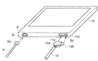
そこで、実施形態2においては、この点に注目し、図8に示すように、ケーブルの接続端子41、43を、X線入射面と対向する背面に設けた開口部40aと、直交する側面に設けた開口部40bとの2箇所に配置する。それぞれの接続端子41、43は、開閉可能なカバー42、44に覆われており、カバー42、44は、閉じる方向に図示しないばねで付勢されている。
Therefore, in the second embodiment, paying attention to this point, as shown in FIG. 8, the
また、可搬可能に使用する際は、図9に示すように、実施形態1と同様に側面の接続端子41を使用し、Cアームに装着して使用する際は、図10に示すように、背面の接続端子43を使用する。Cアームに装着されると、接続先検知部113が装着を検知し、X線像検出部内部の電磁式ロック手段によって側面のカバーがロックされ、背面のカバーがロック解除になる。逆にCアームに装着されていない場合は、側面のカバーがロック解除され、背面のカバーがロック状態になる。このようなインターロック機構により誤って違う箇所に接続しようとするミスを防ぐことができる。
Further, when used in a portable manner, as shown in FIG. 9, the
CアームにX線像検出部10を装着し、背面の接続端子43にケーブル61を接続する。ケーブル51は、X線像検出部の略中央部の位置に収納され、X線像検出部10が回転しても問題ないように巻かれた状態で配置されている。
The X-ray
以上が、実施形態2についての説明である。なお、実施形態2に係わるX線像撮影装置80の動作については、上述した実施形態1を説明した図6と同様となるため、その説明については省略する。
The above is the description of the second embodiment. Note that the operation of the
以上が本発明の代表的な実施形態の一例であるが、本発明は、上記及び図面に示す実施形態に限定することなく、その要旨を変更しない範囲内で適宜変形して実施できるものである。 The above is an example of a typical embodiment of the present invention, but the present invention is not limited to the embodiment described above and shown in the drawings, and can be appropriately modified and implemented without departing from the scope of the present invention. .
例えば、X線像検出部10は、無線通信機能を備えていてもよい。この場合について図11を用いて簡単に説明する。図11には、上述した実施形態1と同様の撮影台20と、無線通信機能を備えたX線像検出部10とを組み合わせた場合の構成の一例が示される。ここで、X線像検出部10は、無線通信を行なう接続手段71と有線通信を行なう接続手段72との両者を具備して構成される。収納部24内にX線像検出部10が装着され、X線像検出部10の接続端子72に対してケーブル12が接続された場合は、実施形態1と同様に動画撮影モードで高フレームレートによる撮影が許可される。一方、天板21上で可搬可能に使用する場合、X線像撮影装置80は、まず、X線像検出部10との間の無線での通信を確立する。この結果、X線像検出部10が認識された場合、無線により両者は通信を開始する。このときの撮影モードは、静止画撮影モードのみが許可される。以下の動作は、実施形態1と同様となるため、説明を省略する。
For example, the X-ray
また、X線像検出部10と組み合わされる支持部は、上述した撮影台20に限定されるものではない。例えば、立位スタンドやユニバーサルスタンド等であってもよい。
The support unit combined with the X-ray
なお、本発明は、例えば、システム、装置、方法、プログラム若しくは記録媒体等としての実施態様を採ることもできる。具体的には、複数の機器から構成されるシステムに適用してもよいし、また、一つの機器からなる装置に適用してもよい。 It should be noted that the present invention can take the form of, for example, a system, apparatus, method, program, or recording medium. Specifically, the present invention may be applied to a system composed of a plurality of devices, or may be applied to an apparatus composed of a single device.
また、本発明は、ソフトウェアのプログラムをシステム或いは装置に直接或いは遠隔から供給し、そのシステム或いは装置に内蔵されたコンピュータが該供給されたプログラムコードを読み出して実行することにより実施形態の機能が達成される場合をも含む。この場合、供給されるプログラムは実施形態で図に示したフローチャートに対応したコンピュータプログラムである。 Further, the present invention achieves the functions of the embodiments by supplying a software program directly or remotely to a system or apparatus, and reading and executing the supplied program code by a computer incorporated in the system or apparatus. This includes cases where In this case, the supplied program is a computer program corresponding to the flowchart shown in the drawings in the embodiment.
従って、本発明の機能処理をコンピュータで実現するために、該コンピュータにインストールされるプログラムコード自体も本発明を実現するものである。つまり、本発明は、本発明の機能処理を実現するためのコンピュータプログラム自体も含まれる。その場合、プログラムの機能を有していれば、オブジェクトコード、インタプリタにより実行されるプログラム、OS(Operating System)に供給するスクリプトデータ等の形態であってもよい。 Accordingly, since the functions of the present invention are implemented by computer, the program code installed in the computer also implements the present invention. In other words, the present invention includes a computer program itself for realizing the functional processing of the present invention. In that case, as long as it has the function of a program, it may be in the form of object code, a program executed by an interpreter, script data supplied to an OS (Operating System), or the like.
コンピュータプログラムを供給するためのコンピュータ読み取り可能な記録媒体としては以下が挙げられる。例えば、フロッピー(登録商標)ディスク、ハードディスク、光ディスク、光磁気ディスク、MO、CD−ROM、CD−R、CD−RW、磁気テープ、不揮発性のメモリカード、ROM、DVD(DVD−ROM,DVD−R)などである。 Examples of the computer-readable recording medium for supplying the computer program include the following. For example, floppy (registered trademark) disk, hard disk, optical disk, magneto-optical disk, MO, CD-ROM, CD-R, CD-RW, magnetic tape, nonvolatile memory card, ROM, DVD (DVD-ROM, DVD- R).
その他、プログラムの供給方法としては、クライアントコンピュータのブラウザを用いてインターネットのホームページに接続し、該ホームページから本発明のコンピュータプログラムをハードディスク等の記録媒体にダウンロードすることが挙げられる。この場合、ダウンロードされるプログラムは、圧縮され自動インストール機能を含むファイルであってもよい。また、本発明のプログラムを構成するプログラムコードを複数のファイルに分割し、それぞれのファイルを異なるホームページからダウンロードすることによっても実現可能である。つまり、本発明の機能処理をコンピュータで実現するためのプログラムファイルを複数のユーザに対してダウンロードさせるWWWサーバも、本発明に含まれるものである。 As another program supply method, a client computer browser is used to connect to a homepage on the Internet, and the computer program of the present invention is downloaded from the homepage to a recording medium such as a hard disk. In this case, the downloaded program may be a compressed file including an automatic installation function. It can also be realized by dividing the program code constituting the program of the present invention into a plurality of files and downloading each file from a different homepage. That is, a WWW server that allows a plurality of users to download a program file for realizing the functional processing of the present invention on a computer is also included in the present invention.
また、本発明のプログラムを暗号化してCD−ROM等の記録媒体に格納してユーザに配布するという形態をとることもできる。この場合、所定の条件をクリアしたユーザに、インターネットを介してホームページから暗号を解く鍵情報をダウンロードさせ、その鍵情報を使用して暗号化されたプログラムを実行し、プログラムをコンピュータにインストールさせるようにもできる。 Further, the program of the present invention may be encrypted, stored in a recording medium such as a CD-ROM, and distributed to users. In this case, a user who has cleared a predetermined condition is allowed to download key information for decryption from a homepage via the Internet, execute an encrypted program using the key information, and install the program on the computer. You can also.
また、コンピュータが、読み出したプログラムを実行することによって、前述した実施形態の機能が実現される他、そのプログラムの指示に基づき、コンピュータ上で稼動しているOSなどとの協働で実施形態の機能が実現されてもよい。この場合、OSなどが、実際の処理の一部又は全部を行ない、その処理によって前述した実施形態の機能が実現される。 In addition to the functions of the above-described embodiment being realized by the computer executing the read program, the embodiment of the embodiment is implemented in cooperation with an OS or the like running on the computer based on an instruction of the program. A function may be realized. In this case, the OS or the like performs part or all of the actual processing, and the functions of the above-described embodiments are realized by the processing.
更に、記録媒体から読み出されたプログラムが、コンピュータに挿入された機能拡張ボードやコンピュータに接続された機能拡張ユニットに備わるメモリに書き込まれて前述の実施形態の機能の一部或いは全てが実現されてもよい。この場合、機能拡張ボードや機能拡張ユニットにプログラムが書き込まれた後、そのプログラムの指示に基づき、その機能拡張ボードや機能拡張ユニットに備わるCPU(Central Processing Unit)などが実際の処理の一部又は全部を行なう。 Furthermore, the program read from the recording medium is written in a memory provided in a function expansion board inserted into the computer or a function expansion unit connected to the computer, so that part or all of the functions of the above-described embodiments are realized. May be. In this case, after a program is written to the function expansion board or function expansion unit, the CPU (Central Processing Unit) provided in the function expansion board or function expansion unit is a part of the actual processing or based on the instructions of the program. Do everything.
10 X線像検出部
80 X線像撮影装置
81 X線発生部
82 制御部
83 表示部
111 第1の接続部
112 第2の接続部
113 接続先検知部
114 撮影動作決定部
DESCRIPTION OF
Claims (9)
前記放射線の入射面と直交する前記検出部の側面に設けられ、可搬可能に使用される場合に前記検出部の制御部との接続に使用される第1の接続手段と、
前記放射線の入射面と対向する前記検出部の背面に設けられ、支持部により固定して使用される場合に前記制御部との接続に使用される第2の接続手段と
を備えることを特徴とする放射線画像撮影装置。 A detector for capturing a radiographic image by detecting radiation from the rays generating unit release that transmitted through the Utsushitai,
A first connection means provided on a side surface of the detection unit orthogonal to the incident surface of the radiation and used for connection with the control unit of the detection unit when used in a portable manner;
A second connecting means provided on a back surface of the detection unit facing the radiation incident surface and used for connection to the control unit when used by being fixed by a support unit ;
Radiographic imaging apparatus comprising: a.
前記接続先検知手段による検知結果に基づいて前記撮影の動作を決定する決定手段とを更に備え、
前記決定手段は、
前記第1の接続手段により接続されていると検知された場合、前記第2の接続手段により接続される場合よりも前記撮影のフレームレートを低くすることを特徴とする請求項1記載の放射線画像撮影装置。 A connection destination detection means for detecting which of the first connection means and the second connection means is connected to the control unit;
A decision means for deciding the photographing operation based on a detection result by the connection destination detection means;
The determining means includes
The radiographic image according to claim 1 , wherein when it is detected that the connection is made by the first connection means, the frame rate of the imaging is made lower than the case where the connection is made by the second connection means. Shooting device.
前記制御部との間で行なわれる通信に用いられ、通信プロトコルがそれぞれ異なる
ことを特徴とする請求項1又は2に記載の放射線画像撮影装置。 The first connecting means and the second connecting means are:
The radiographic imaging apparatus according to claim 1, wherein the radiographic imaging apparatus is used for communication performed with the control unit and has different communication protocols.
その接続に用いられる接続端子の形状がそれぞれ異なる
ことを特徴とする請求項1乃至3いずれか1項に記載の放射線画像撮影装置。 The first connecting means and the second connecting means are:
The radiographic imaging apparatus according to claim 1, wherein the connection terminals used for the connection have different shapes.
前記接続先検知手段により接続されている旨が検知された接続手段の通信仕様に基づいて前記検出部の撮影駆動方式を決定する
ことを特徴とする請求項2に記載の放射線画像撮影装置。 The determining means includes
The radiographic image capturing apparatus according to claim 2 , wherein an imaging drive method of the detection unit is determined based on a communication specification of the connection unit that is detected to be connected by the connection destination detection unit.
前記第2の接続手段は、前記制御部との間で行なわれる有線による通信に用いられる
ことを特徴とする請求項1乃至5いずれか1項に記載の放射線画像撮影装置。 The first connection means is used for wireless communication performed with the control unit,
The radiographic imaging apparatus according to claim 1, wherein the second connection unit is used for wired communication performed with the control unit.
前記接続端子はそれぞれ、閉じる方向へ付勢された開閉可能なカバーに覆われることを特徴とする請求項1に記載の放射線画像撮影装置。The radiographic imaging apparatus according to claim 1, wherein each of the connection terminals is covered with an openable / closable cover that is biased in a closing direction.
前記第2の接続手段が使用される場合、前記第1の接続手段に対応するカバーを閉位置でロックするロック手段 When the second connecting means is used, a locking means for locking the cover corresponding to the first connecting means in the closed position.
を更に備えることを特徴とする請求項7に記載の放射線画像撮影装置。The radiographic imaging apparatus according to claim 7, further comprising:
前記検出部が、
前記放射線の入射面と直交する前記検出部の側面に設けられ、可搬可能に使用される場合に前記検出部の制御部との接続に使用される第1の接続手段、前記放射線の入射面と対向する前記検出部の背面に設けられ、支持部により固定して使用される場合に前記制御部との接続に使用される第2の接続手段のいずれを用いて前記検出部が前記制御部と接続されているかを検知する接続先検知工程
を有することを特徴とする放射線画像撮影装置の制御方法。 A method of controlling a radiation image capturing apparatus which immediately Bei detection unit for capturing a radiographic image by detecting radiation from the rays generating unit release that transmitted through the Utsushitai,
The detection unit is
Provided on a side surface of the detector perpendicular to the plane of incidence of the radiation, the first connecting means that is used to connect the control unit of the detector when the portable can be used, the incident surface of the radiation and it provided on the back surface of the detector facing the detection unit and the control unit using any of the second connecting means that is used to connect to the control unit when used in fixing the support part as the connection destination detection engineering to detect whether it is connected to the
The method of radiographic image capturing apparatus characterized by having a.
Priority Applications (2)
| Application Number | Priority Date | Filing Date | Title |
|---|---|---|---|
| JP2008220500A JP5538694B2 (en) | 2008-08-28 | 2008-08-28 | Radiation imaging apparatus and control method thereof |
| US12/506,360 US7924982B2 (en) | 2008-08-28 | 2009-07-21 | Radiographic imaging apparatus and control method thereof |
Applications Claiming Priority (1)
| Application Number | Priority Date | Filing Date | Title |
|---|---|---|---|
| JP2008220500A JP5538694B2 (en) | 2008-08-28 | 2008-08-28 | Radiation imaging apparatus and control method thereof |
Related Child Applications (1)
| Application Number | Title | Priority Date | Filing Date |
|---|---|---|---|
| JP2014094045A Division JP5832584B2 (en) | 2014-04-30 | 2014-04-30 | X-ray image detector and X-ray imaging apparatus |
Publications (3)
| Publication Number | Publication Date |
|---|---|
| JP2010051594A JP2010051594A (en) | 2010-03-11 |
| JP2010051594A5 JP2010051594A5 (en) | 2011-09-22 |
| JP5538694B2 true JP5538694B2 (en) | 2014-07-02 |
Family
ID=41725434
Family Applications (1)
| Application Number | Title | Priority Date | Filing Date |
|---|---|---|---|
| JP2008220500A Active JP5538694B2 (en) | 2008-08-28 | 2008-08-28 | Radiation imaging apparatus and control method thereof |
Country Status (2)
| Country | Link |
|---|---|
| US (1) | US7924982B2 (en) |
| JP (1) | JP5538694B2 (en) |
Families Citing this family (15)
| Publication number | Priority date | Publication date | Assignee | Title |
|---|---|---|---|---|
| JP5675062B2 (en) | 2009-06-05 | 2015-02-25 | キヤノン株式会社 | X-ray imaging device |
| JP5586878B2 (en) | 2009-06-08 | 2014-09-10 | キヤノン株式会社 | X-ray imaging device |
| JP5580573B2 (en) | 2009-11-09 | 2014-08-27 | キヤノン株式会社 | Control device, radiation imaging system, control method, management method, and program |
| JP5917029B2 (en) * | 2011-06-24 | 2016-05-11 | キヤノン株式会社 | X-ray imaging apparatus and X-ray imaging control method |
| CN102970848B (en) * | 2011-08-31 | 2016-12-28 | Ge医疗系统环球技术有限公司 | X-ray detector and heat dissipating method |
| JP5984432B2 (en) * | 2012-03-01 | 2016-09-06 | キヤノン株式会社 | X-ray equipment |
| JP5988618B2 (en) * | 2012-03-02 | 2016-09-07 | キヤノン株式会社 | Radiation imaging apparatus, control apparatus, and control method thereof |
| US20130279661A1 (en) * | 2012-04-19 | 2013-10-24 | Canon Kabushiki Kaisha | Radiant ray generation control apparatus, radiation imaging system, and method for controlling the same |
| JP6224901B2 (en) | 2013-03-14 | 2017-11-01 | キヤノン株式会社 | Mobile radiographic imaging apparatus, control method for mobile radiographic imaging apparatus, and program |
| US10772589B2 (en) * | 2014-09-23 | 2020-09-15 | Samsung Electronics Co., Ltd. | Receiving device and X-ray imaging apparatus having the same |
| KR20160064940A (en) * | 2014-11-28 | 2016-06-08 | 삼성전자주식회사 | X-ray imaging apparatus |
| US10379437B2 (en) * | 2014-11-28 | 2019-08-13 | Samsung Electronics Co., Ltd. | X-ray detector and X-ray imaging apparatus having the same |
| JP6662385B2 (en) * | 2015-07-17 | 2020-03-11 | コニカミノルタ株式会社 | Radiation imaging apparatus and radiation imaging system |
| JP6134992B2 (en) * | 2015-07-31 | 2017-05-31 | 富士フイルム株式会社 | Radiation irradiation equipment |
| US10531847B2 (en) * | 2016-07-18 | 2020-01-14 | Samsung Electronics Co., Ltd. | X-ray detector and X-ray imaging apparatus having the same |
Family Cites Families (7)
| Publication number | Priority date | Publication date | Assignee | Title |
|---|---|---|---|---|
| JP3610348B2 (en) * | 2001-08-27 | 2005-01-12 | キヤノン株式会社 | Cassette type imaging apparatus and radiation imaging apparatus |
| JP4454970B2 (en) | 2003-06-13 | 2010-04-21 | キヤノン株式会社 | X-ray imaging device |
| JP2008134057A (en) * | 2005-03-10 | 2008-06-12 | Konica Minolta Medical & Graphic Inc | Radiation image detector and radiation image photographing system |
| CN100569182C (en) * | 2005-03-25 | 2009-12-16 | 柯尼卡美能达医疗印刷器材株式会社 | Radiation image obtains equipment and radiation image obtains system |
| US7787014B2 (en) * | 2005-12-19 | 2010-08-31 | General Electric Company | Systems, apparatus and methods for portable imaging |
| JP4817365B2 (en) * | 2006-03-03 | 2011-11-16 | 株式会社日立メディコ | X-ray diagnostic equipment |
| JP5224726B2 (en) * | 2006-07-10 | 2013-07-03 | キヤノン株式会社 | Radiation imaging apparatus and control method thereof |
-
2008
- 2008-08-28 JP JP2008220500A patent/JP5538694B2/en active Active
-
2009
- 2009-07-21 US US12/506,360 patent/US7924982B2/en not_active Expired - Fee Related
Also Published As
| Publication number | Publication date |
|---|---|
| JP2010051594A (en) | 2010-03-11 |
| US20100054404A1 (en) | 2010-03-04 |
| US7924982B2 (en) | 2011-04-12 |
Similar Documents
| Publication | Publication Date | Title |
|---|---|---|
| JP5538694B2 (en) | Radiation imaging apparatus and control method thereof | |
| JP3990914B2 (en) | Radiation imaging equipment | |
| KR100992469B1 (en) | Radiographic apparatus | |
| JP5580573B2 (en) | Control device, radiation imaging system, control method, management method, and program | |
| JP5438714B2 (en) | Radiography equipment | |
| US7988356B2 (en) | Radiographic imaging apparatus and method | |
| JP5167966B2 (en) | Radiographic imaging system and radiographic image detector | |
| JP4078096B2 (en) | Radiation imaging equipment | |
| JP5630250B2 (en) | Radiation imaging system | |
| JP2004141240A (en) | Radiation detection cassette, and image information management system | |
| JP2006320532A (en) | Radiographic system | |
| JP2006055201A (en) | Radiographic apparatus, radiographic system and radiographic method | |
| JP5832584B2 (en) | X-ray image detector and X-ray imaging apparatus | |
| JP2012157666A (en) | Radiation image photographing system | |
| JP2009205155A (en) | Radiation detection apparatus | |
| JP5776166B2 (en) | Radiation imaging system | |
| JP4464149B2 (en) | Radiation imaging equipment | |
| JP3989659B2 (en) | Radiation detection cassette | |
| JP2010167259A (en) | Radiographic image capturing system, processor, and radiographic image capturing method | |
| JP5619203B2 (en) | Radiation imaging apparatus, control apparatus, and control method | |
| JP5773048B2 (en) | Correction data generation method and radiographic imaging system of radiographic imaging apparatus | |
| JP2009077891A (en) | Radiation imaging cassette | |
| JP2009291338A (en) | Radiation image capturing system | |
| JP2010012060A (en) | Portable radiation image detector and radiation image photographing system | |
| JP2005204860A (en) | Radiographic apparatus |
Legal Events
| Date | Code | Title | Description |
|---|---|---|---|
| A521 | Request for written amendment filed |
Free format text: JAPANESE INTERMEDIATE CODE: A523 Effective date: 20110804 |
|
| A621 | Written request for application examination |
Free format text: JAPANESE INTERMEDIATE CODE: A621 Effective date: 20110804 |
|
| A977 | Report on retrieval |
Free format text: JAPANESE INTERMEDIATE CODE: A971007 Effective date: 20130328 |
|
| A131 | Notification of reasons for refusal |
Free format text: JAPANESE INTERMEDIATE CODE: A131 Effective date: 20130527 |
|
| A521 | Request for written amendment filed |
Free format text: JAPANESE INTERMEDIATE CODE: A523 Effective date: 20130716 |
|
| TRDD | Decision of grant or rejection written | ||
| A01 | Written decision to grant a patent or to grant a registration (utility model) |
Free format text: JAPANESE INTERMEDIATE CODE: A01 Effective date: 20140331 |
|
| R151 | Written notification of patent or utility model registration |
Ref document number: 5538694 Country of ref document: JP Free format text: JAPANESE INTERMEDIATE CODE: R151 |
|
| A61 | First payment of annual fees (during grant procedure) |
Free format text: JAPANESE INTERMEDIATE CODE: A61 Effective date: 20140430 |