JP5538390B2 - System and method for collecting plasma protein fractions from separated blood components - Google Patents
System and method for collecting plasma protein fractions from separated blood components Download PDFInfo
- Publication number
- JP5538390B2 JP5538390B2 JP2011523014A JP2011523014A JP5538390B2 JP 5538390 B2 JP5538390 B2 JP 5538390B2 JP 2011523014 A JP2011523014 A JP 2011523014A JP 2011523014 A JP2011523014 A JP 2011523014A JP 5538390 B2 JP5538390 B2 JP 5538390B2
- Authority
- JP
- Japan
- Prior art keywords
- plasma
- blood
- separator
- protein
- separated
- Prior art date
- Legal status (The legal status is an assumption and is not a legal conclusion. Google has not performed a legal analysis and makes no representation as to the accuracy of the status listed.)
- Active
Links
- 108010017384 Blood Proteins Proteins 0.000 title claims description 47
- 102000004506 Blood Proteins Human genes 0.000 title claims description 47
- 238000000034 method Methods 0.000 title claims description 44
- 239000012503 blood component Substances 0.000 title claims description 41
- 210000004369 blood Anatomy 0.000 claims description 164
- 239000008280 blood Substances 0.000 claims description 164
- 102000004169 proteins and genes Human genes 0.000 claims description 51
- 108090000623 proteins and genes Proteins 0.000 claims description 51
- 238000000926 separation method Methods 0.000 claims description 50
- 239000000306 component Substances 0.000 claims description 36
- 239000012528 membrane Substances 0.000 claims description 35
- 238000002617 apheresis Methods 0.000 claims description 30
- 230000008569 process Effects 0.000 claims description 11
- 239000011148 porous material Substances 0.000 claims description 10
- 238000005194 fractionation Methods 0.000 claims description 9
- 239000012510 hollow fiber Substances 0.000 claims description 9
- 239000012141 concentrate Substances 0.000 claims description 4
- 108010058237 plasma protein fraction Proteins 0.000 claims 5
- 229940081857 plasma protein fraction Drugs 0.000 claims 5
- 238000005086 pumping Methods 0.000 claims 1
- 210000003743 erythrocyte Anatomy 0.000 description 64
- 238000012545 processing Methods 0.000 description 34
- 239000012530 fluid Substances 0.000 description 29
- 239000007788 liquid Substances 0.000 description 20
- 239000003146 anticoagulant agent Substances 0.000 description 18
- 229940127219 anticoagulant drug Drugs 0.000 description 18
- 210000001772 blood platelet Anatomy 0.000 description 10
- 238000000605 extraction Methods 0.000 description 10
- 238000012546 transfer Methods 0.000 description 9
- 238000010586 diagram Methods 0.000 description 7
- 210000000265 leukocyte Anatomy 0.000 description 7
- 230000037452 priming Effects 0.000 description 7
- 238000003860 storage Methods 0.000 description 6
- 230000000712 assembly Effects 0.000 description 5
- 238000000429 assembly Methods 0.000 description 5
- 108010088751 Albumins Proteins 0.000 description 4
- 102000009027 Albumins Human genes 0.000 description 4
- LFQSCWFLJHTTHZ-UHFFFAOYSA-N Ethanol Chemical compound CCO LFQSCWFLJHTTHZ-UHFFFAOYSA-N 0.000 description 4
- 230000004888 barrier function Effects 0.000 description 4
- 210000004180 plasmocyte Anatomy 0.000 description 4
- FAPWRFPIFSIZLT-UHFFFAOYSA-M Sodium chloride Chemical compound [Na+].[Cl-] FAPWRFPIFSIZLT-UHFFFAOYSA-M 0.000 description 3
- 238000005119 centrifugation Methods 0.000 description 3
- 238000004587 chromatography analysis Methods 0.000 description 3
- 238000001802 infusion Methods 0.000 description 3
- 238000012986 modification Methods 0.000 description 3
- 230000004048 modification Effects 0.000 description 3
- 108010054218 Factor VIII Proteins 0.000 description 2
- 102000001690 Factor VIII Human genes 0.000 description 2
- 108010049003 Fibrinogen Proteins 0.000 description 2
- 102000008946 Fibrinogen Human genes 0.000 description 2
- 241000209149 Zea Species 0.000 description 2
- 235000005824 Zea mays ssp. parviglumis Nutrition 0.000 description 2
- 235000002017 Zea mays subsp mays Nutrition 0.000 description 2
- 230000008901 benefit Effects 0.000 description 2
- 230000000740 bleeding effect Effects 0.000 description 2
- 230000017531 blood circulation Effects 0.000 description 2
- 230000001413 cellular effect Effects 0.000 description 2
- 235000005822 corn Nutrition 0.000 description 2
- 230000006378 damage Effects 0.000 description 2
- 229960000301 factor viii Drugs 0.000 description 2
- 229940012952 fibrinogen Drugs 0.000 description 2
- 238000005534 hematocrit Methods 0.000 description 2
- 230000002572 peristaltic effect Effects 0.000 description 2
- 230000000717 retained effect Effects 0.000 description 2
- 238000001228 spectrum Methods 0.000 description 2
- 108010047303 von Willebrand Factor Proteins 0.000 description 2
- 102100036537 von Willebrand factor Human genes 0.000 description 2
- 229960001134 von willebrand factor Drugs 0.000 description 2
- 108090000935 Antithrombin III Proteins 0.000 description 1
- 102000004411 Antithrombin III Human genes 0.000 description 1
- 108010039209 Blood Coagulation Factors Proteins 0.000 description 1
- 102000015081 Blood Coagulation Factors Human genes 0.000 description 1
- 102100022641 Coagulation factor IX Human genes 0.000 description 1
- 206010053567 Coagulopathies Diseases 0.000 description 1
- 108010076282 Factor IX Proteins 0.000 description 1
- 108010080379 Fibrin Tissue Adhesive Proteins 0.000 description 1
- 230000005526 G1 to G0 transition Effects 0.000 description 1
- 108060003951 Immunoglobulin Proteins 0.000 description 1
- 108090000190 Thrombin Proteins 0.000 description 1
- 230000004913 activation Effects 0.000 description 1
- 208000007502 anemia Diseases 0.000 description 1
- 229960005348 antithrombin iii Drugs 0.000 description 1
- 238000013459 approach Methods 0.000 description 1
- 238000003556 assay Methods 0.000 description 1
- 239000003114 blood coagulation factor Substances 0.000 description 1
- 238000010241 blood sampling Methods 0.000 description 1
- 230000006727 cell loss Effects 0.000 description 1
- 230000035602 clotting Effects 0.000 description 1
- 238000004891 communication Methods 0.000 description 1
- 238000001816 cooling Methods 0.000 description 1
- 238000007872 degassing Methods 0.000 description 1
- 229960004222 factor ix Drugs 0.000 description 1
- 239000000835 fiber Substances 0.000 description 1
- 238000003306 harvesting Methods 0.000 description 1
- 102000018358 immunoglobulin Human genes 0.000 description 1
- 239000004615 ingredient Substances 0.000 description 1
- 230000000977 initiatory effect Effects 0.000 description 1
- 238000004519 manufacturing process Methods 0.000 description 1
- 238000002156 mixing Methods 0.000 description 1
- 239000002991 molded plastic Substances 0.000 description 1
- 238000004806 packaging method and process Methods 0.000 description 1
- 210000002381 plasma Anatomy 0.000 description 1
- 238000002360 preparation method Methods 0.000 description 1
- 230000001681 protective effect Effects 0.000 description 1
- 230000009467 reduction Effects 0.000 description 1
- 150000003384 small molecules Chemical class 0.000 description 1
- 230000001954 sterilising effect Effects 0.000 description 1
- 238000004659 sterilization and disinfection Methods 0.000 description 1
- 230000001225 therapeutic effect Effects 0.000 description 1
- 238000002560 therapeutic procedure Methods 0.000 description 1
- 229960004072 thrombin Drugs 0.000 description 1
- 238000003466 welding Methods 0.000 description 1
Images


Classifications
-
- A—HUMAN NECESSITIES
- A61—MEDICAL OR VETERINARY SCIENCE; HYGIENE
- A61M—DEVICES FOR INTRODUCING MEDIA INTO, OR ONTO, THE BODY; DEVICES FOR TRANSDUCING BODY MEDIA OR FOR TAKING MEDIA FROM THE BODY; DEVICES FOR PRODUCING OR ENDING SLEEP OR STUPOR
- A61M1/00—Suction or pumping devices for medical purposes; Devices for carrying-off, for treatment of, or for carrying-over, body-liquids; Drainage systems
- A61M1/36—Other treatment of blood in a by-pass of the natural circulatory system, e.g. temperature adaptation, irradiation ; Extra-corporeal blood circuits
-
- A—HUMAN NECESSITIES
- A61—MEDICAL OR VETERINARY SCIENCE; HYGIENE
- A61M—DEVICES FOR INTRODUCING MEDIA INTO, OR ONTO, THE BODY; DEVICES FOR TRANSDUCING BODY MEDIA OR FOR TAKING MEDIA FROM THE BODY; DEVICES FOR PRODUCING OR ENDING SLEEP OR STUPOR
- A61M1/00—Suction or pumping devices for medical purposes; Devices for carrying-off, for treatment of, or for carrying-over, body-liquids; Drainage systems
- A61M1/34—Filtering material out of the blood by passing it through a membrane, i.e. hemofiltration or diafiltration
- A61M1/3496—Plasmapheresis; Leucopheresis; Lymphopheresis
-
- A—HUMAN NECESSITIES
- A61—MEDICAL OR VETERINARY SCIENCE; HYGIENE
- A61M—DEVICES FOR INTRODUCING MEDIA INTO, OR ONTO, THE BODY; DEVICES FOR TRANSDUCING BODY MEDIA OR FOR TAKING MEDIA FROM THE BODY; DEVICES FOR PRODUCING OR ENDING SLEEP OR STUPOR
- A61M1/00—Suction or pumping devices for medical purposes; Devices for carrying-off, for treatment of, or for carrying-over, body-liquids; Drainage systems
- A61M1/36—Other treatment of blood in a by-pass of the natural circulatory system, e.g. temperature adaptation, irradiation ; Extra-corporeal blood circuits
- A61M1/3621—Extra-corporeal blood circuits
- A61M1/3622—Extra-corporeal blood circuits with a cassette forming partially or totally the blood circuit
- A61M1/36222—Details related to the interface between cassette and machine
-
- A—HUMAN NECESSITIES
- A61—MEDICAL OR VETERINARY SCIENCE; HYGIENE
- A61M—DEVICES FOR INTRODUCING MEDIA INTO, OR ONTO, THE BODY; DEVICES FOR TRANSDUCING BODY MEDIA OR FOR TAKING MEDIA FROM THE BODY; DEVICES FOR PRODUCING OR ENDING SLEEP OR STUPOR
- A61M1/00—Suction or pumping devices for medical purposes; Devices for carrying-off, for treatment of, or for carrying-over, body-liquids; Drainage systems
- A61M1/36—Other treatment of blood in a by-pass of the natural circulatory system, e.g. temperature adaptation, irradiation ; Extra-corporeal blood circuits
- A61M1/3621—Extra-corporeal blood circuits
- A61M1/3622—Extra-corporeal blood circuits with a cassette forming partially or totally the blood circuit
- A61M1/36224—Extra-corporeal blood circuits with a cassette forming partially or totally the blood circuit with sensing means or components thereof
-
- A—HUMAN NECESSITIES
- A61—MEDICAL OR VETERINARY SCIENCE; HYGIENE
- A61M—DEVICES FOR INTRODUCING MEDIA INTO, OR ONTO, THE BODY; DEVICES FOR TRANSDUCING BODY MEDIA OR FOR TAKING MEDIA FROM THE BODY; DEVICES FOR PRODUCING OR ENDING SLEEP OR STUPOR
- A61M1/00—Suction or pumping devices for medical purposes; Devices for carrying-off, for treatment of, or for carrying-over, body-liquids; Drainage systems
- A61M1/36—Other treatment of blood in a by-pass of the natural circulatory system, e.g. temperature adaptation, irradiation ; Extra-corporeal blood circuits
- A61M1/3621—Extra-corporeal blood circuits
- A61M1/3622—Extra-corporeal blood circuits with a cassette forming partially or totally the blood circuit
- A61M1/36225—Extra-corporeal blood circuits with a cassette forming partially or totally the blood circuit with blood pumping means or components thereof
-
- A—HUMAN NECESSITIES
- A61—MEDICAL OR VETERINARY SCIENCE; HYGIENE
- A61M—DEVICES FOR INTRODUCING MEDIA INTO, OR ONTO, THE BODY; DEVICES FOR TRANSDUCING BODY MEDIA OR FOR TAKING MEDIA FROM THE BODY; DEVICES FOR PRODUCING OR ENDING SLEEP OR STUPOR
- A61M1/00—Suction or pumping devices for medical purposes; Devices for carrying-off, for treatment of, or for carrying-over, body-liquids; Drainage systems
- A61M1/36—Other treatment of blood in a by-pass of the natural circulatory system, e.g. temperature adaptation, irradiation ; Extra-corporeal blood circuits
- A61M1/3621—Extra-corporeal blood circuits
- A61M1/3622—Extra-corporeal blood circuits with a cassette forming partially or totally the blood circuit
- A61M1/36226—Constructional details of cassettes, e.g. specific details on material or shape
- A61M1/362262—Details of incorporated reservoirs
-
- A—HUMAN NECESSITIES
- A61—MEDICAL OR VETERINARY SCIENCE; HYGIENE
- A61M—DEVICES FOR INTRODUCING MEDIA INTO, OR ONTO, THE BODY; DEVICES FOR TRANSDUCING BODY MEDIA OR FOR TAKING MEDIA FROM THE BODY; DEVICES FOR PRODUCING OR ENDING SLEEP OR STUPOR
- A61M1/00—Suction or pumping devices for medical purposes; Devices for carrying-off, for treatment of, or for carrying-over, body-liquids; Drainage systems
- A61M1/36—Other treatment of blood in a by-pass of the natural circulatory system, e.g. temperature adaptation, irradiation ; Extra-corporeal blood circuits
- A61M1/3621—Extra-corporeal blood circuits
- A61M1/3622—Extra-corporeal blood circuits with a cassette forming partially or totally the blood circuit
- A61M1/36226—Constructional details of cassettes, e.g. specific details on material or shape
- A61M1/362265—Details of valves
-
- A—HUMAN NECESSITIES
- A61—MEDICAL OR VETERINARY SCIENCE; HYGIENE
- A61M—DEVICES FOR INTRODUCING MEDIA INTO, OR ONTO, THE BODY; DEVICES FOR TRANSDUCING BODY MEDIA OR FOR TAKING MEDIA FROM THE BODY; DEVICES FOR PRODUCING OR ENDING SLEEP OR STUPOR
- A61M1/00—Suction or pumping devices for medical purposes; Devices for carrying-off, for treatment of, or for carrying-over, body-liquids; Drainage systems
- A61M1/36—Other treatment of blood in a by-pass of the natural circulatory system, e.g. temperature adaptation, irradiation ; Extra-corporeal blood circuits
- A61M1/3621—Extra-corporeal blood circuits
- A61M1/3622—Extra-corporeal blood circuits with a cassette forming partially or totally the blood circuit
- A61M1/36226—Constructional details of cassettes, e.g. specific details on material or shape
- A61M1/362266—Means for adding solutions or substances to the blood
-
- A—HUMAN NECESSITIES
- A61—MEDICAL OR VETERINARY SCIENCE; HYGIENE
- A61M—DEVICES FOR INTRODUCING MEDIA INTO, OR ONTO, THE BODY; DEVICES FOR TRANSDUCING BODY MEDIA OR FOR TAKING MEDIA FROM THE BODY; DEVICES FOR PRODUCING OR ENDING SLEEP OR STUPOR
- A61M1/00—Suction or pumping devices for medical purposes; Devices for carrying-off, for treatment of, or for carrying-over, body-liquids; Drainage systems
- A61M1/36—Other treatment of blood in a by-pass of the natural circulatory system, e.g. temperature adaptation, irradiation ; Extra-corporeal blood circuits
- A61M1/3693—Other treatment of blood in a by-pass of the natural circulatory system, e.g. temperature adaptation, irradiation ; Extra-corporeal blood circuits using separation based on different densities of components, e.g. centrifuging
- A61M1/3696—Other treatment of blood in a by-pass of the natural circulatory system, e.g. temperature adaptation, irradiation ; Extra-corporeal blood circuits using separation based on different densities of components, e.g. centrifuging with means for adding or withdrawing liquid substances during the centrifugation, e.g. continuous centrifugation
-
- A—HUMAN NECESSITIES
- A61—MEDICAL OR VETERINARY SCIENCE; HYGIENE
- A61M—DEVICES FOR INTRODUCING MEDIA INTO, OR ONTO, THE BODY; DEVICES FOR TRANSDUCING BODY MEDIA OR FOR TAKING MEDIA FROM THE BODY; DEVICES FOR PRODUCING OR ENDING SLEEP OR STUPOR
- A61M1/00—Suction or pumping devices for medical purposes; Devices for carrying-off, for treatment of, or for carrying-over, body-liquids; Drainage systems
- A61M1/36—Other treatment of blood in a by-pass of the natural circulatory system, e.g. temperature adaptation, irradiation ; Extra-corporeal blood circuits
- A61M1/38—Removing constituents from donor blood and storing or returning remainder to body, e.g. for transfusion
-
- A—HUMAN NECESSITIES
- A61—MEDICAL OR VETERINARY SCIENCE; HYGIENE
- A61M—DEVICES FOR INTRODUCING MEDIA INTO, OR ONTO, THE BODY; DEVICES FOR TRANSDUCING BODY MEDIA OR FOR TAKING MEDIA FROM THE BODY; DEVICES FOR PRODUCING OR ENDING SLEEP OR STUPOR
- A61M2202/00—Special media to be introduced, removed or treated
- A61M2202/04—Liquids
- A61M2202/0413—Blood
- A61M2202/0415—Plasma
-
- A—HUMAN NECESSITIES
- A61—MEDICAL OR VETERINARY SCIENCE; HYGIENE
- A61M—DEVICES FOR INTRODUCING MEDIA INTO, OR ONTO, THE BODY; DEVICES FOR TRANSDUCING BODY MEDIA OR FOR TAKING MEDIA FROM THE BODY; DEVICES FOR PRODUCING OR ENDING SLEEP OR STUPOR
- A61M2202/00—Special media to be introduced, removed or treated
- A61M2202/07—Proteins
-
- A—HUMAN NECESSITIES
- A61—MEDICAL OR VETERINARY SCIENCE; HYGIENE
- A61M—DEVICES FOR INTRODUCING MEDIA INTO, OR ONTO, THE BODY; DEVICES FOR TRANSDUCING BODY MEDIA OR FOR TAKING MEDIA FROM THE BODY; DEVICES FOR PRODUCING OR ENDING SLEEP OR STUPOR
- A61M2205/00—General characteristics of the apparatus
- A61M2205/12—General characteristics of the apparatus with interchangeable cassettes forming partially or totally the fluid circuit
Landscapes
- Health & Medical Sciences (AREA)
- Heart & Thoracic Surgery (AREA)
- Vascular Medicine (AREA)
- Biomedical Technology (AREA)
- Engineering & Computer Science (AREA)
- Anesthesiology (AREA)
- Hematology (AREA)
- Life Sciences & Earth Sciences (AREA)
- Animal Behavior & Ethology (AREA)
- General Health & Medical Sciences (AREA)
- Public Health (AREA)
- Veterinary Medicine (AREA)
- Cardiology (AREA)
- External Artificial Organs (AREA)
- Medicines Containing Material From Animals Or Micro-Organisms (AREA)
Description
本出願は、2008年8月12日出願の米国仮特許出願第61/088154号、2008年9月3日出願の米国仮特許出願第61/093892号、2008年9月17日出願の米国仮特許出願第61/097598号及び2008年12月8日出願の米国仮特許出願第61/120763号についての米国特許法第119条(e)による利益を主張する。
This application is filed with US Provisional Patent Application No. 61/088154 filed on August 12, 2008, US Provisional Patent Application No. 61/093892 filed on September 3, 2008, and US Provisional Application filed on September 17, 2008. We claim the benefit of US Patent Section 119 (e) for
本出願は、2009年4月24日出願の米国特許出願第12/429325号に関連する。 This application is related to US patent application Ser. No. 12 / 429,325, filed Apr. 24, 2009.
血液及び血液成分の輸血のため、1人の献血者からの全血は、通常、血漿、赤血球及び血小板の3つの成分に分離される。それぞれの成分は、多様な特定の状態及び病状を治療するのに使用することができる。例えば、赤血球成分は、貧血を治療し、出血による赤血球喪失を補充するために使用することができ、濃縮した血小板成分は、出血を制御するために使用することができ、血漿成分は、血液量を増加させるために患者に与えることができ、又は採取した後、オフラインで、フィブリノーゲン、フォンウイルブランド因子、第VIII因子、第IX因子、アンチトロンビンIII、フィブリンのり(Fibrin sealant)、トロンビン、アルファI及びIVIGなどの個々の血漿タンパク質に分離することができる。複数の献血者からの血漿は、採取して一緒に混合又は一緒に貯留することもでき、この混合された血漿液の貯留液は、所望の血漿タンパク質に分画することもできる。 Due to the transfusion of blood and blood components, whole blood from a single blood donor is usually separated into three components: plasma, red blood cells, and platelets. Each component can be used to treat a variety of specific conditions and conditions. For example, the red blood cell component can be used to treat anemia and replenish red blood cell loss due to bleeding, the concentrated platelet component can be used to control bleeding, and the plasma component is the blood volume Can be given to patients to increase or after collection offline, fibrinogen, von Willebrand factor, factor VIII, factor IX, antithrombin III, fibrin sealant, thrombin, alpha I And can be separated into individual plasma proteins such as IVIG. Plasma from multiple blood donors can be collected and mixed together or pooled together, and the pooled plasma fluid pool can be fractionated into the desired plasma proteins.
採取した血漿成分をタンパク質又は血漿の様々な成分又は画分に分離することは、血漿分画と呼ばれる。このような分画は、通常、多くの献血者からの血漿を混合して、冷アルコール分画(コーン分画としても知られている)及びクロマトグラフィーの公知技法を使用することにより個々の血漿タンパク質を濃縮する、大型の分画器によって実施する。 Separating collected plasma components into various components or fractions of protein or plasma is called plasma fractionation. Such fractions are usually obtained by mixing plasma from many blood donors and using individual techniques for cold alcohol fractionation (also known as corn fractionation) and chromatographic techniques. Performed by a large fractionator that concentrates the protein.
1人の献血者から分離した血液成分を得るには伝統的に2つの方法がある。1つの方法は、献血者から全血を採取し、全血を採取してからしばらく時間が経った後全血を各成分に分離することである。この方法を利用すると、全血は、発熱物質がなく滅菌されており、採取される血液の量にとって十分な抗凝固剤を含有する認可済み容器内に採取される。この方法で採取された全血は、実験室で技術者によって各成分に分離されるが、分離は通常、米国では採取から約2時間から8時間後に、欧州では約2時間から24時間後に行われる。 There are traditionally two ways to obtain a separate blood component from a blood donor. One method is to collect whole blood from blood donors and separate the whole blood into components after some time has passed since the collection of whole blood. Using this method, whole blood is collected in an approved container that is pyrogen-free and sterilized and contains sufficient anticoagulant for the amount of blood collected. Whole blood collected in this way is separated into individual components by a technician in the laboratory, but the separation is usually performed about 2 to 8 hours after collection in the United States and about 2 to 24 hours after collection in Europe. Is called.
全血を各成分に分離するための別の方法は、アフェレーシス装置(apheresis device)を使用することによるものである。このアフェレーシス装置は、オンラインでこの装置に接続された1人の献血者からの全血を自動的に各成分に分離し、採取しない不要な任意の血液成分は採取手順の間に献血者に返送される。 Another method for separating whole blood into components is by using an apheresis device. This apheresis device automatically separates whole blood from a single blood donor connected to this device online into individual components, and any unnecessary blood components not collected are returned to the donor during the collection procedure. Is done.
アフェレーシス装置を使用して、献血された血液の細胞成分から血漿成分を分離することができる。アフェレーシス装置は、採取しない成分を返送するため、1人の献血者による献血回数の増加が可能になる。 An apheresis device can be used to separate plasma components from cellular components of donated blood. Since the apheresis device returns components that are not collected, the number of blood donations by one blood donor can be increased.
本発明は、分離容器を回転させるステップと、回転している分離容器内で血漿を他の血液成分から分離するステップと、分離した血漿を回転している分離容器から血漿分離器に供給するステップと、血漿分離器を使用して血漿を血漿タンパク質に分離するステップと、少なくとも一部の血漿タンパク質を採取するステップとを含む、血漿画分を採取する方法を含むことができる。 The present invention includes a step of rotating a separation container, a step of separating plasma from other blood components in the rotating separation container, and a step of supplying separated plasma to the plasma separator from the rotating separation container And collecting a plasma fraction using a plasma separator and separating the plasma into plasma proteins and collecting at least a portion of the plasma proteins.
本発明のさらなる態様は、ローターと、ローターに取り付けられてローターと共に回転する分離容器であって、ローターの回転中に血液がその中で血漿及び他の成分に分離される分離容器と、分離容器に流路として(fluidly)接続されて、回転している分離容器から分離した血漿を受ける血漿分離器と、血漿分離器内にある中空糸を有する膜であって、分離した血漿から少なくともいくつかの血漿タンパク質を分離することができる膜と、血漿分離器から分離した血漿タンパク質を採取するための、血漿分離器に流路として接続されている採取容器とを含む、アフェレーシス血漿分離システムである。 A further aspect of the present invention is a rotor, a separation vessel attached to the rotor and rotating with the rotor, wherein the blood is separated into plasma and other components therein during rotation of the rotor, and the separation vessel And a membrane having a hollow fiber in the plasma separator, which is fluidly connected to receive the separated plasma from the rotating separation container, and at least some of the separated plasma An apheresis plasma separation system comprising a membrane capable of separating the plasma proteins of and a collection container connected as a flow path to the plasma separator for collecting the plasma proteins separated from the plasma separator.
本発明の別の態様は、ある時間の間に血漿分離器に入る液体の量を決定するステップと、この時間の間に、血漿分離器内で血漿から分離され、血漿分離器から出る血漿タンパク質の量を測定するステップと、当該流出量に対する流入量の比率を求めることにより、血漿分離器から出る血漿タンパク質の濃度を予測するステップとを含む、血漿分離器を使用して採取されるタンパク質の濃度を予測する方法を含む。 Another aspect of the present invention is to determine the amount of liquid that enters the plasma separator during a period of time, and during this time, the plasma protein that is separated from the plasma in the plasma separator and exits the plasma separator Measuring the amount of the protein collected using the plasma separator, the method comprising: determining the concentration of plasma protein exiting the plasma separator by determining the ratio of the inflow to the outflow Includes methods for predicting concentration.
本発明のさらなる態様は、回転している分離容器内で、血漿を他の血液成分から分離するステップと、回転している分離容器からの血漿を血漿タンパク質に分離するステッと、さらに任意選択で血漿分画プロセスにおいて所望の血漿タンパク質を濃縮するステップとを含む、方法によって生成される、血漿タンパク質生成物に関する。 A further aspect of the invention further comprises the steps of separating plasma from other blood components in a rotating separation vessel, further separating the plasma from the rotating separation vessel into plasma proteins, and optionally further. Concentrating a desired plasma protein in a plasma fractionation process.
本発明の追加の態様は、取出/返送アセンブリと、取出/返送アセンブリに流路として接続されている分離容器と、分離容器に流路として接続されている膜型血漿分離器を含む血漿採取アセンブリと、膜型血漿分離器に流路として接続されている採取容器とを含む、予め接続された使い捨てセットに関する。 An additional aspect of the present invention is a plasma collection assembly comprising an extraction / return assembly, a separation container connected as a flow path to the extraction / return assembly, and a membrane plasma separator connected as a flow path to the separation container And a pre-connected disposable set including a collection container connected to the membrane plasma separator as a flow path.
類似の要素は、類似の数を用いて表していることに留意されたい。本発明を、TRIMA(登録商標)自動採取システム(製造販売:CaridianBCT社、Lakewood、コロラド州、米国)を参照しながら説明するが、CaridianBCT社が製造販売するCOBE(登録商標)SPECTRAシステム、SPECTRA OPTIA(登録商標)システム及びTRIMA ACCEL(登録商標)自動採取システムなど(但し、これらに限定されない)の任意のアフェレーシスシステムを、本発明の精神及び範囲を逸脱しない範囲で使用することができることに留意されたい。 Note that similar elements are represented using similar numbers. The present invention will be described with reference to a TRIMA® automated collection system (manufactured and sold by: Caridian BCT, Lakewood, Colorado, USA), the COBE® SPECTRA system, SPECTRA OPTIA manufactured and sold by Caridian BCT. It is noted that any apheresis system such as, but not limited to, a TRIMA® system and a TRIMA ACCEL® automated collection system may be used without departing from the spirit and scope of the present invention. I want.
本発明は、Fenwal社(Lake Zurich、イリノイ州、米国)製造のAutophereis Cシステム又はHaemonetics社(Bainbridge、マサチューセッツ州)製造のPCSシステムなど、他の製造会社のアフェレーシスシステムで使用することもできる。 The present invention can also be used in an apheresis system of another manufacturing company, such as the Autopheris C system manufactured by Fenwal (Lake Zurich, Illinois, USA) or the PCS system manufactured by Haemonetics (Bainbridge, Mass.).
血液のアフェレーシスシステム2を図1に例示するが、これは連続した血液成分の分離プロセスを可能にする。一般的に、連続システムにおいて、全血が献血者/患者4から採血されて血液成分分離装置6に供給され、ここで血液は個々の血液成分に分離され、装置6から、これらの血液成分の少なくとも1つの成分が取り出され、他の成分は献血者に返送される。連続システム2は、血漿をさらに血漿タンパク質に分離又は濃縮して採取することも提供する。
A blood apheresis system 2 is illustrated in FIG. 1, which allows a continuous blood component separation process. In general, in a continuous system, whole blood is drawn from a donor /
血液のアフェレーシスシステム2において、血液は、献血者/患者4から採血され、体外チューブ回路10、血液処理容器352及び血漿分離器又は濃縮器205を含む、予め接続された使い捨てセット8を経て導かれ、これによって、完全に閉鎖され滅菌されたシステムが画定される。使い捨てセット8は、体外チューブ回路10と連結するためのポンプ/バルブ/センサのアセンブリ1000、及び使い捨て血液処理容器352と連結するためのチャンネルアセンブリ200を含む、血液成分分離装置6上に取り付けられる。
In the blood apheresis system 2, blood is drawn from a donor /
チャンネルアセンブリ200は、血液をその様々なタイプの血液成分に遠心分離により分離するのに必要な遠心力を与える遠心分離機の回転可能なローターアセンブリ568に回転自在に相互接続される、チャンネル収容部(channel housing)204を含む。血液処理容器352は、チャンネル収容部内の溝又はチャンネルに適合するようにチャンネル収容部204内に嵌め込まれている。血液は、こうして献血者/患者4から、体外チューブ回路10を通って、回転している血液処理容器352へと流れる。血液処理容器352内の血液は様々なタイプの血液成分に分離され、これらの血液成分タイプ(例えば血漿、赤血球)の少なくとも1つが、血液処理容器352から、連続的に取り出される。次いで、血漿成分はさらに血漿タンパク質に濃縮又は分離することができる。また、採取のため又は治療上の処置における使用のために保持しない血液成分は、血液処理容器352から取り出されて、体外チューブ回路10を介して献血者/患者4に返送される。血液処理容器352は、任意選択で、血小板の採取にも使用することができるが、このような採取については説明しない。
血液成分分離装置6の操作は、1つ又は複数のプロセッサによって制御されるが、これは図示していない。アフェレーシスシステム2の操作者をその操作の様々の面で助けるために、血液成分分離装置6は、タッチスクリーンの入力/出力装置664付きグラフィカルインターフェース660を含む。
The operation of the
下記のアフェレーシスシステムを、赤血球の採取及び血漿タンパク質の採取に関して説明する。しかし、必要であれば血漿の採取のみも可能であることは理解される。血漿の採取のみが望まれ、続けて血漿タンパク質の分離又は採取を伴うのであれば、下記に記載したシステムを簡略化してもよい。例えば、赤血球の採取アセンブリ950を削除してもよい。通気バッグチューブサブアセンブリ(vent bag tubing subassembly)100及び置換液アセンブリ(replacement fluid assembly)960も任意選択としてもよい。赤血球を採取せずに血漿タンパク質のみを採取するのであれば簡略化した閉鎖システムにすることができる。
The following apheresis system is described with respect to red blood cell collection and plasma protein collection. However, it is understood that only plasma collection is possible if necessary. If only plasma collection is desired, followed by plasma protein separation or collection, the system described below may be simplified. For example, the red blood
図2に例示するように、血液に適合可能な(blood−primable)予め接続された体外チューブ回路10は、カセットアセンブリ110及びいくつかのチューブアセンブリ20、50、60、950、90、100、並びに任意選択でこれらに相互接続される960を含む。一般的に、血液取出/返送チューブアセンブリ20は、献血者/患者4とカセットアセンブリ110の間に単一のニードル連結部(interface)を与え、血液取込み/血液成分移送サブアセンブリ(blood inlet/blood component tubing subassembly)60は、カセットアセンブリ110と血液処理容器352の間に連結部(interface)を与える。抗凝固剤チューブアセンブリ50、血漿又は血漿タンパク質の採取チューブアセンブリ90、赤血球の採取アセンブリ950及び通気バッグチューブサブアセンブリ100は、カセットアセンブリ110とも相互接続されている。さらに血小板の採取を望むのであれば、血小板の採取チューブアセンブリを含んでもよい。任意選択で、置換液サブアセンブリ960を含んでもよい。上記のアセンブリ又はサブ−アセンブリを含む体外チューブ回路10及び血液処理容器352は相互接続されており、単回の使用のための、閉鎖された使い捨てシステム又は予め接続された使い捨てシステムが得られる。
As illustrated in FIG. 2, a blood-primable pre-connected
血液の取出/返送チューブアセンブリ20は、共通の多岐管(manifold)28を介して血液取出チューブ22、血液返送チューブ24及び抗凝固剤チューブ26と相互接続されたニードルサブアセンブリ30を含む。ニードルサブアセンブリ30は、保護ニードルスリーブ34及びニードルキャップ36を有するニードル32、並びにニードル32と多岐管28の間にある相互接続チューブ38を含む。ニードルサブアセンブリ30は、さらにDスリーブ40及び相互接続チューブ38の周りに配置されたチューブクランプ42を含む。血液取出チューブ22に、血液サンプリングサブアセンブリ46と相互接続されたY型コネクタ44を付けてもよい。
The blood withdrawal /
血液取出/返送アセンブリは、貯蔵部150の底部に接続された第1の一体型の流路190a、チューブループ192、並びにチューブループ192及び血液返送チューブ24に相互接続された第2の一体型の液体流路を含む。
The blood withdrawal / return assembly includes a first
カセットアセンブリ110は、熱溶接で接合される前と後ろの成形プラスチックプレート(図示せず)を含み、一体型の液体流路を有する長方形のカセット部材115を画定する。カセットアセンブリ110は、様々な一体型の流路を相互接続させる、下記に記載するいくつかの外に延在するチューブループをさらに含む。一体型の流路は様々なチューブアセンブリとも相互接続されている。
図3に示されるように、カセットアセンブリ110は、血液の取出/返送チューブアセンブリ20の抗凝固剤チューブ26と相互接続されている第1の一体型抗凝固剤流路120aを含む。カセットアセンブリ110は、第2の一体型抗凝固剤流路120b、並びに第1及び第2の一体型抗凝固剤流路120aと120bの間にポンプが係合している抗凝固剤チューブループ122をさらに含む。第2の一体型抗凝固剤流路120bは、抗凝固剤チューブアセンブリ50に相互接続されている。抗凝固剤チューブアセンブリ50は、抗凝固剤源に接続できる点滴チャンバ(spike drip chamber)52(図2)、抗凝固剤送液チューブ54及び滅菌バリアフィルター56を含む。使用の間、抗凝固剤チューブアセンブリ50は、抗凝固剤を献血者/患者4から取り出した血液に与えて、体外チューブ回路10における任意の凝固を減らす又は妨げる。
As shown in FIG. 3, the
カセットアセンブリ110は、血液取出/返送チューブアセンブリ20の血液取出チューブ22と相互接続された、第1の一体型血液取込み流路130aをも含む。カセットアセンブリ110は、第2の一体型血液取込み流路130b及び第1及び第2の一体型血液取込み流路130a及び130bの間にポンプが係合している血液取込みチューブループ132をさらに含む。第1の一体型血液取込み流路130aは、第1の圧力センサモジュール134及び入口フィルター136を含み、第2の一体型血液取込み流路130bは、第2の圧力センサモジュール138を含む。第2の一体型血液取込み流路130bは、血液取込み/血液成分移送アセンブリ60の血液取込みチューブ62と相互接続されている。
The
血液取込みチューブ62は、血液処理容器352の入力ポート392とも相互接続されており、全血を血液処理容器へ供給して処理させる。分離血液成分をカセットアセンブリ110に戻すために、血液取込み/血液成分移送アセンブリ60は、出口ポート520付きの赤血球(RBC)取出しチューブ64及び出口ポート456付きの血漿取出しチューブ68をさらに含む。連結部を制御するための制御ポートは61で示す。
The
血液取込みチューブ62、RBC取出しチューブ64及び血漿取出しチューブ68はすべて第1及び第2の歪み緩和部材72及び74並びにその間にある編まれた軸受け部材76を通過する。これは、米国特許第4425112号に教示されるように、継ぎ目のない相互接続を可能にする利点がある。図示されているように、多管コネクタ78を様々なチューブラインにおいて使用することができる。
任意選択の置換液移送アセンブリ960は、生理食塩溶液などの置換液(又は、例えば置換/交換RBC若しくは血漿)を献血者/患者4に送液するために設けることができる。図示されたように、置換液アセンブリ960は、内部の置換液流路140aと流路として連通されてカセット110に取り付けられている少なくとも1つの置換液入口チューブライン962を含み、流路140aが次に置換液移送ループ142に接続され、それがカセット110及び内部の置換液流路140bに接続し戻される。別の2つの内部流路又はスパー(spur)144a及び144b並びにチューブループ146も図示されている。内部流路144bは、その中を又はそれを通って液体が全く流れないように遮断される。出口のチューブラインはこれに接続されないことが好ましく、また流路144bを省いてもよい。
An optional replacement
置換液アセンブリ960は、好ましくは、図示されるようにY型コネクタ969を介してチューブライン962に接続することができる、任意選択で付設された滅菌バリア装置966a〜966b及びチューブ接続ライン968a〜968bを持つ1つ又は複数のスパイクアセンブリ964a〜964bをさらに含む。1つ又は複数のスライドクランプ970も含めてよい。使用の前に血漿タンパク質を凍結させてもよいので、滅菌バリア装置966a〜966bは任意選択である。
The
置換液アセンブリはこのような液体を140a及びチューブループ142を介して導入されているように図示されているが、これらは例示のためのものである。言い換えると、この液体は、チューブループ162などの返送のための他のチューブループを介して導入することができ、又はこのような液体をチューブを介してシステム内に吸引することでさえ可能である。
The replacement fluid assembly is illustrated as introducing such liquid via 140a and
血液取込み/血液成分移送アセンブリ60の血漿取出しチューブ68は、カセットアセンブリ110の第1の一体型血漿流路160aと相互接続されている。カセットアセンブリ110は、第1の一体型血漿流路160a及び第2の一体型血漿流路160bを相互接続させ、ポンプが係合している、血漿チューブループ162をさらに含む。第2の一体型血漿流路160bは、第1及び第2のスパー164a及び164bを含む。第1のスパー164aは、血漿採取チューブアセンブリ90と相互接続されている。血漿採取チューブアセンブリ90を用いて、使用中に血漿を採取することができ、これは、血漿コレクタチューブ92、分離器205、血漿コレクタチューブ93及び1つ又は複数の血漿採取バッグ、容器(container)又は貯蔵部94を含む。スライドクランプ96は、血漿コレクタチューブ93の上に置いてもよい。血漿採取チューブアセンブリ90は、下記に、より詳しく記載するように血漿成分をさらに分離させるために使用することもできる。
The
第2の一体型血漿流路160bの第2のスパー164bは、血漿を献血者/患者4に返送するために、血漿返送チューブループ166に相互接続されている。この目的のため、血漿返送チューブループ166は、カセットアセンブリ110の血液返送貯蔵部150の頭部と相互接続されている。
The
血漿返送アセンブリはまた、血漿を分離又は濃縮させた後返送する。分離した後の返送は、チューブ962、分岐管140a及び140b並びにポンプが係合している血漿チューブループ142に接続しているチューブ963を含む。スパー144bは、血漿返送ループ又はチューブ146に接続されており、血漿をカセット貯蔵部150に送液して、最終的に献血者/患者4に送液する。同様に、このサブアセンブリを使用して、962、140a、チューブループ142、140b及び146を通して置換液を送液して、貯蔵部150に戻すことができる。置換液が必要でなければ、チューブ963との接続部の上の置換液サブアセンブリに関連するチューブ962の部分は省略してもよい。
The plasma return assembly also returns after the plasma has been separated or concentrated. The return after separation includes the
血漿返送アセンブリは、血漿をチューブループ142を介して返送するところが図示されているが、血漿は162のような別のポンプループ配置を介して返送することもできる。
Although the plasma return assembly is shown returning plasma through the
血漿採取チューブアセンブリは、中空糸膜の分離器又は濃縮器205を含む、図4に示される血漿分離サブアセンブリを含む。チューブ92は、分離器205の入口203に相互接続されている。チューブ93は、膜型分離器205の出口206に相互接続されている。血漿採取チューブアセンブリ90は、採取するべきではない血漿又はタンパク質を返送するために第2の出口208に相互接続されているチューブ963も含む。返送チューブ963を含む血漿返送アセンブリは、上記に記載のように、チューブ962及び分岐管140aに接続されている。
The plasma collection tube assembly includes a plasma separation subassembly shown in FIG. 4 that includes a hollow fiber membrane separator or
血漿タンパク質濃縮器又は血漿分離器205は、第1の先端キャップ214に入口203及び反対側の先端キャップ216に出口206を含む。
The plasma protein concentrator or
中空糸膜は、2つの先端キャップ214及び216の間に配置されている。このような中空糸膜212は、繊維の中に毛細管内部空間(IC)を含み、中空糸の外側に毛細管外部空間(EC)を含む。中空糸を形成する膜の孔径は、血漿、又は任意選択で選択された分子量のタンパク質などの成分がICとECの空間の間を通過できるように選択することができる。したがって、分離した血漿がチューブ92及び入口203を通ってIC空間に入ると、膜孔を通ってEC空間に通過できる血漿及び任意のタンパク質は、出口208及びチューブ963を通過することになろう。
The hollow fiber membrane is disposed between the two
下記の表1は様々なタンパク質画分及びこれらのキロダルトン単位の分子量を示している。膜の孔径は、表に示したものなどの、所望のタンパク質画分以外のすべてが膜を通過するようにカットオフ値を持つよう選択することができる。例えば、孔径は50キロダルトン未満のものすべてを通過させるようなものでもよく、或いは、孔径は、カットオフ値が50kDaから1300kDaで選択される範囲のものが、膜を通過するように選択することもできる。 Table 1 below shows the various protein fractions and the molecular weights of these kilodalton units. The pore size of the membrane can be selected to have a cutoff value so that all but the desired protein fraction passes through the membrane, such as those shown in the table. For example, the pore size may be anything that passes less than 50 kilodaltons, or the pore size should be selected so that the cutoff range between 50 kDa and 1300 kDa passes through the membrane. You can also.

例えば、分子量が50kDa未満である成分のみが通過するような孔径を有する膜の場合、表1のあらゆるタンパク質は出口206で採取され、タンパク質がより少ない血漿だけが出口208から返送される。
For example, for a membrane with a pore size that allows only components with a molecular weight of less than 50 kDa to pass through, any protein in Table 1 is collected at
別の例では、分子量が150kDa未満である成分のみが返送されるような孔径を有する膜の場合、分子量が150kDaより大きい一部のタンパク質だけが採取されることになる。血漿及び分子量が150kDa未満の他の血漿タンパク質は膜を通って出口208に流れよう。
In another example, in the case of a membrane having a pore size such that only components with a molecular weight of less than 150 kDa are returned, only a portion of the protein with a molecular weight greater than 150 kDa will be collected. Plasma and other plasma proteins with a molecular weight of less than 150 kDa will flow through the membrane to the
血液取込み/血液成分移送アセンブリ60のRBC取出しチューブ64は、カセットアセンブリ110の一体型RBC流路170に相互接続されている(図3)。一体型RBC流路170は、第1及び第2のスパー170a及び170bをそれぞれ含む。第1のスパー170aは、分離されたRBCを献血者/患者4に返送するためにRBC返送チューブループ172に相互接続されている。このような目的のため、RBC返送チューブループ172は、カセットアセンブリ110の血液返送貯蔵部150の頭部に相互接続されている。第2のスパー170bは、赤血球を採取するべきでなければ、閉鎖してもよいし、或いはRBC採取チューブアセンブリ950に接続することもできる。
The
RBC採取チューブアセンブリ950は、RBCコレクタチューブ952、少なくとも1つのRBC採取貯蔵部、容器又はバッグ954、及び滅菌バリアフィルター/ドリップスパイクアセンブリ956を含む。1つ又はより多くの実用的な数のRBCバッグ954の(図示せず)をコレクタチューブ952に接続してもよい。さらに、ここでは図示されていないが、1つ又は複数の白血球(WBC)濾過器及び/又はRBC貯蔵溶液接続部及び/又はバッグは、RBC採取チューブアセンブリ950に予め接続していてもよく及び/又はその構成部品として含んでもよい。
RBC
通気バッグチューブアセンブリ100は、カセットアセンブリ110の血液返送貯蔵部150の頭部にも相互接続されている。通気バッグチューブアセンブリ100は、通気孔チューブ102及び通気バッグ104を含む。使用中、カセットアセンブリ110内、特に血液返送貯蔵部150内に包装時から存在する滅菌空気は、通気孔チューブ102及び通気バッグ104への流入及び流出を繰り返すが、これについてさらに詳しく説明する。
The vent
図3に例示するように、ポンプが係合している、チューブループ122、132、142、162及び192はカセット部材115から延在して非対称の配置をもたらし、これにより、カセットアセンブリ110を血液成分分離装置6に容易に正しく取り付けて使用することができる。
As illustrated in FIG. 3, the
標準の操作において、全血はニードルアセンブリ30、血液取出チューブ22、カセットアセンブリ110及び血液取込みチューブ62を通って処理容器352に移動する。次いで、全血は、容器352において血液成分に分離される。生成物を採取する間、RBC及び血漿は容器352から、対応するポート520及び456を通って流出して採取され、続いて血漿タンパク質が分離及び/又は返送される。
In standard operation, whole blood travels through the
カセットアセンブリにおいて、上部及び下部超音波センサ(図示せず)を有する貯蔵部150は、血液処理モードの間、返送血液が、それぞれの血液返送/交換送液サブモード中に貯蔵部150から取り出され、それぞれの血液取出サブモード中に蓄積されるように設けられる。採取しない血小板及び血漿(及び恐らく、白血球も)又は採取されなかった赤血球及び/又は置換液が貯蔵部150内に上部超音波レベルセンサ(図示せず)にまで蓄積されると、ポンプループ192と関連するポンプ1090の動作が起動し、血液又は交換成分を貯蔵部150から190a、192及び190bを介して取り出し、これらを返送/送液チューブ24及びニードルアセンブリ20を介して献血者/患者4に返還する。貯蔵部150内の液体レベルが下部超音波レベルセンサのレベルまで低下すると、返送/送液蠕動ポンプ1090は自動的に停止し、血液取出サブモードを再起動する。次いで、血液取出サブモード及び血液返送/交換送液サブモードのサイクルが所定量の血小板、RBC又は他の採取される血液成分が得られるまで続くことになる。
In the cassette assembly, a
カセット110をポンプ/バルブ/センサのアセンブリ1000に取り付けると、ポンプ1040がチューブポンプループ142と結び付き、ポンプ1066がチューブループ162と結び付き、ポンプ1030がチューブループ132と結び付き、ポンプ1020がチューブループ122と結び付き、ポンプ1090がチューブループ192と結び付く。
When
チャンネルアセンブリ200は、回転式遠心分離ローターアセンブリ568上に配置され(図1)、使い捨て血液処理容器352を受けるチャンネル収容部204を含む。
The
チャンネル収容部204には、血液が所望の態様で血液成分タイプに分離され得るように血液処理容器352が取り付けられる。
A
これに関して、チャンネル収容部204は、血液処理容器352が配置される、概ねくぼんだチャンネル(図示せず)を含む。
In this regard, the
血液処理チャンネル容器352は、チャンネル収容部204が回転する間、血液が血液処理容器352に供給され、遠心分離で様々な血液成分タイプに分離され、またチャンネル収容部204が回転している間、血液処理容器352から様々な血液成分タイプが取り出せるようにチャンネル収容部204内に配置される。さらに、このチャンネルは、遠心分離の間、(例えば、このチャンネル内に血液処理容器352を保持することにより及び血液処理容器352の所望の輪郭を維持することにより)血液処理容器352と相互に作用することも望ましい。加えて、該チャンネルは、血液処理容器352の血液プライミング(すなわち、アフェレーシス手順で、血液を血液処理容器352に供給する第1の液体として使用すること)を可能にする。
The blood
血液処理容器352は、アフェレーシス手順では、血液の流れに直接接続して、流れを受け入れるようにチャンネル収容部204のチャンネル内に配置される。血液処理容器352を使用すると、各アフェレーシス手順後のチャンネル収容部204を滅菌する必要性が軽減され、また容器352を廃棄して、使い捨てシステムを提供してもよい。血液処理容器352は、チャンネル内で独立して立つのに十分な剛性であるように構築されている。さらに、血液処理容器352はまた、上記の外形を有してチャンネル内に装着されるのに十分な剛性である。しかし、血液処理容器352はまた、アフェレーシス手順の間、チャンネルの形状にほぼ合致するように十分に柔軟でなければならない。血液処理容器及びアフェレーシスシステムの部品のより詳細は、米国特許第6,514,189Blに記載されている。
The
図2に示されるように、血液は取込みチューブ62から血液取込みポート392を通って血液処理容器352の内部に導入される。血液取込みポート392は、血液処理容器352の内側部分に延在している。
As shown in FIG. 2, blood is introduced from the
血液取込みポート392により血液処理容器352に供給される血液は、少なくともRBC及び/又は血漿に分離される。
The blood supplied to the
分離した血漿は、ポート456及びチューブ68を介して血液処理容器から出る。分離した赤血球は、ポート520及びチューブ64を介して血液から出る。
Separated plasma exits the blood processing vessel via
アフェレーシスシステムは、図3で1120、1110及び1100で概略的に示されている、様々なバルブアセンブリを含む。これらのバルブは、ポンプ/バルブ/センサのアセンブリ1000の一部である。
The apheresis system includes various valve assemblies, shown schematically at 1120, 1110 and 1100 in FIG. These valves are part of the pump / valve /
本明細書において記載されるアフェレーシスシステムは、連続血漿分離ステップにより、赤血球(RBC)及び/又は血漿の連続分離を提供する。例えば、連続分離は、RBC及び血漿を両方同時に採取することにより、及び/又はRBC又は血漿のどちらかを別々に採取することにより提供することができる。さらに血漿を分離するために、血漿をRBCと共に又は血漿のみを採取してもよい。採取されなかった成分は献血者に再輸血して返送される。バッフィコート成分、すなわち血小板及びWBCは、記載したように別に採取されないことに留意されたい。むしろ、これらの成分はこれらの手順の間ずっと、RBCと共に残留することがあり、後で濾過して取り除く。例えばWBCは、白血球削減フィルター等により濾過して取り除くか、又はRBC生成物と共に保持するか、若しくは献血者に返送するかのいずれかを行うことができる。血漿生成物は、乏血小板のままで、WBCを含まない(又は少なくとも公布の最低安全範囲内)ものとすることができる。 The apheresis system described herein provides continuous separation of red blood cells (RBC) and / or plasma by a continuous plasma separation step. For example, continuous separation can be provided by collecting both RBC and plasma simultaneously and / or by collecting either RBC or plasma separately. In order to further separate the plasma, the plasma may be collected with RBC or only plasma. Uncollected ingredients are returned to the donor for re-transfusion. Note that the buffy coat components, ie platelets and WBC, are not collected separately as described. Rather, these components may remain with the RBC throughout these procedures and are later filtered off. For example, the WBC can be either filtered out with a leukocyte reduction filter or the like, retained with the RBC product, or returned to the blood donor. The plasma product can remain platelet poor and be free of WBC (or at least within the minimum safe range of promulgation).
本実施形態において、RBC及び血漿の同時採取又は血漿のみの採取に関する選択肢のみを記載するが、血小板の採取を別の選択肢としてもよい。血漿及びRBCの両方を採取すべき1つのアプローチでは、血液アフェレーシスシステム2を利用して、ある第1の時間の間にRBC及び血漿を同時に採取することができ、次いで、第2の時間の間に血漿又は赤血球のいずれかを採取することができる。これは2重の赤血球生成物又は2重の血漿生成物を含み、この2重の生成物の量は使用者によって設定することができる。 In the present embodiment, only the options related to the simultaneous collection of RBC and plasma or the collection of only plasma are described, but the collection of platelets may be another option. In one approach where both plasma and RBC should be collected, blood apheresis system 2 can be used to collect RBC and plasma simultaneously during a first time, and then during a second time. Either plasma or red blood cells can be collected. This includes a double erythrocyte product or a double plasma product, the amount of which can be set by the user.
置換液も任意選択で本発明の手順の範囲内で与えてもよい。滅菌生理食塩溶液は、本明細書で使用が考慮される置換液の選択肢の1つである。したがって、血漿及び/又はRBCの多量の液体量が献血者/患者から採血される場合/とき、引き換えに置換液を送液することにより、献血者/患者を十分に水分補給し得る。 A replacement fluid may also optionally be provided within the scope of the present procedure. Sterile saline solution is one of the replacement solution options contemplated for use herein. Therefore, when / when a large amount of plasma and / or RBC fluid is collected / from a blood donor / patient, the blood donor / patient can be sufficiently hydrated by delivering a replacement fluid in exchange.
血液処理が始まると、血漿は1つ又は複数の貯蔵部94内に採取され、及び/又は赤血球は1つ又は複数の貯蔵部954内に採取される。或いは、貯蔵部954内へのRBCの採取又は貯蔵部94内への血漿の採取のいずれかを、個々の手順で選択的に完了させることもできる。いずれかの採取手順の間、血液成分分離装置6は、好ましくは連続した血液取出及び血液返送の起動及び終了を制御する。さらに、血液成分分離装置6は、所定のプロトコルに従った血漿及びRBCの採取プロセスを制御するであろう。これは、好ましくはポンプ/バルブ/センサのアセンブリ1000のバルブアセンブリ1100、1110及び1120、及び/又は適当なポンプ1020、1030、1040、1066及び/又は1090の制御を含む。
When blood processing begins, plasma is collected in one or
初めに、血液プライミングを実施して使い捨てシステム10をプライミングする。血液プライミングの間、プライミング段階であっても、成分分離が開始され、いくつかの血漿が採取されることが望ましい。従って、血漿が出口ポート456を通ってチューブ68へと流出することがある。
Initially, blood priming is performed to prime the
血液プライミング段階の後及び/又は同時に血液分離制御装置6は、任意選択の交換液体ラインもプライミングされ得るようにポンプ/バルブ/センサのアセンブリ1000に制御信号を与える。特に、置換液バルブアセンブリ1100は開口され、置換液入口ポンプ1040のスイッチが入れられて生理食塩溶液(又は他の置換液)を置換液入口チューブ962及び置換液移送ループ142aを通じて置換液導入チューブライン146にポンプ移送し、カセット貯蔵部150における最初の採取が行われるが、この最初のプライミング採取はおそらく及び好ましくは少量の置換液を構成しない。
After and / or at the same time as the blood priming phase, the
プライミングが完了した後、まだなお準備段階中であるが、血液成分分離装置6は、処理容器352から流出したすべての分離した血液成分が先ず返送/送液/貯蔵部150に移動するようにポンプ/バルブ/センサのアセンブリ1000に適当な制御信号を与えることができる。任意選択で、採取の前に、すべての血液成分の分離及び献血者への返送の1つ又は複数サイクルを行ってもよい。また、血液成分分離装置6は、1つ又は複数のこれらの最初の血液成分返送サブモードの間、ポンプループ132に関連付けられている血液取込みポンプアセンブリ1030の動作を継続してもよい。
After priming is complete, the
所望のAC比率を確立するため、血液成分分離装置6は、所定の速度で取込んだ血液流の中に抗凝固剤を導入するように抗凝固剤蠕動ポンプ1020に適当な制御信号を与える。抗凝固処理された血液の血液処理容器352への取込み流速は、献血者/患者4に対する所定の抗凝固剤最大許容注入速度(ACIR)により制限し得る。
In order to establish the desired AC ratio, blood
採取が開始されると、血液成分分離装置6は、血漿迂回バルブアセンブリ1110を切り替えて、容器352からポンプ移送された、分離血漿の流れを血漿取出しチューブ68及び血漿チューブループ162を通じて、血漿コレクタチューブ92へと向け、膜型分離器205の入口203へと通すように制御信号を与える。アフェレーシスシステムの簡略図を示す図5を参照されたい。加えて、血漿だけを採取すべきであれば、赤血球は容器352から取出しチューブ64を通って返送チューブループ172を経て血液返送貯蔵部150へと流れ続ける。しかし、RBCを血漿と同時に採取すべきであれば、赤血球バルブ1120が切り替えられて、チューブ64から流出する分離RBCの流れは、(カセット110の)スパー170bに向けられ、そしてこれを介してチューブライン952に、そしてこれを介して1つ又は複数のRBC採取貯蔵部954に向けられる。
When the collection is started, the blood
採取プロセスのいずれかの間に、1つ又は複数の置換液を献血者/患者4に送液してもよい。したがって、分離装置6が返送モードよりもむしろ採取モード内にある時はいつでも、置換液入口バルブアセンブリ1100は開口することもでき、置換液ポンプ1040は、置換液を、液体源(図示せず)から、チューブライン962、カセット流路140a及び140b、並びにチューブループ142及び146を通じて貯蔵部150へ送液するのを開始する。
One or more replacement fluids may be delivered to the donor /
分離及び採取の間、チャンネル収容部204は、通常、約3000rpmの回転速度で駆動され、準備及び成分採取段階の両方の間、所望のヘマトクリットを達成することができる。これに対して、容器352への血液取込みの流速は、約64.7ml/分未満に設定することができる。所望のヘマトクリットは、RBC及び/又は血漿の採取段階を開始する前に、容器352のおよそ2つの量の全血量を容器352を通過させることにより確実に固定化することができる。
During separation and collection, the
RBC採取段階を開始するために、血液成分分離装置6は、血液処理容器352から取り出されたRBCの流れをRBC採取貯蔵部954に向かわせるようにRBC迂回バルブアセンブリ1120に適当な制御信号を与える。RBCの採取が開始するとすぐに及び/又はそれと同時に、置換液バルブアセンブリ1100は切り替えられて、任意選択で置換液の流れが貯蔵部150にも供給される。
To initiate the RBC collection phase, the blood
分離したRBCは、分離後、採取のために容器352からライン64を経てポンプ移送されないが、その代わりに、容器352に対する血液取込みの流れの相対的圧力によって、容器352から体外チューブ回路10を経て移動される(これは、血漿出口ポート456による血漿出口の圧力により変更することができるようにしてもよい)。その結果として、分離及び採取したRBCの損傷が最小になる。
The separated RBCs are not pumped from the
赤血球の採取とは別に又はそれと連続して行い得る、血漿の採取に関して、分離した血漿は、ポンプ1066によって、血漿採取ライン92を通りフィルター分離器又は濃縮器205を通ってライン93を経て血漿成分採取バッグ94へとポンプ移送される。
With respect to plasma collection, which can be performed separately or in series with red blood cell collection, the separated plasma is pumped by
分離した血漿は、ローター352から、チューブ162がその周りに延在するポンプ1066によって、ポート456、ライン68、流路160a、チューブ162、流路160bを通って、移送され、血漿採取ライン92を介してフィルター又は分離器205内に流れる。フィルター膜を通ってIC側からEC側に移動しない血漿タンパク質の画分は貯蔵バッグ94中に流入する。EC側に移動する残留の血漿及び/又はタンパク質は、フィルター205から、出口208、チューブ963、962、流路140a、チューブループ142、流路140b、チューブ146を通って貯蔵部150に流入し献血者4に返送される。濃縮された血漿生成物は、所望のタンパク質の標準量の数倍の量又は高い濃度を含有することがあるが、単により多くの血漿をフィルター、濃縮器又は分離器205で処理することによって生成することができる。
The separated plasma is transferred from the
所望量の赤血球を採取し、血漿タンパク質を分離及び採取した後、及び血液分離装置6が迂回アセンブリ1110及び1120に、それぞれ分離した血漿及び分離したRBCの流れを貯蔵部150に向けるように制御信号を与えた後、さらなる血液処理を望まないのであれば、次に濯ぎ戻し(rinse back)手順を完了させてもよい。血漿ポンプ1066を返送/送液ポンプ1090の速度と同じ血漿最大速度に設定して濯ぎ戻しを行う。
After collecting the desired amount of red blood cells, separating and collecting plasma proteins, and the
手順の最後に、血漿バッグ94及び赤血球貯蔵部、もしあれば954を、体外チューブ回路1からその接続を切断してもよい。
At the end of the procedure, the
フィルター205の孔径は、すべてのタンパク質が容器94内に採取される又は分子量が十分に大きいタンパク質だけを採取されるかを決める。
The pore size of the
概略図5は別の選択肢も示している。図5に示されるように、血漿分離器205に入る血漿は、ポンプ1066により入口側203に移送され、またポンプ1040により出口(EC)側208に移送される。しかし、ポンプの位置は変えてもよい。例えば、図5に示されるように、ICの出口側にポンプがあってもよい(極細線が1040aを示している)。このポンプは入口ポンプ1066のみと共に使用してもよく(1040を経てEC側にポンプ移送しない)又はポンプ1040のみと共に使用してもよい(1066を経て入口すなわちIC側にポンプで汲み上げない)。このように、2つのポンプを利用するがこのようなポンプの正確な位置は変更してもよい。
The schematic diagram 5 also shows another option. As shown in FIG. 5, plasma entering the
ポンプ1040aで206からIC側に移送することで、IC側に対する陽圧による膜を通した流れが与えられ、こうして、EC側に陰圧を与えるポンプ1066及び1040を使用すると生じるおそれがある、液体の脱気を回避させる。膜212が、ポンプ1040aの使用時に遮断されると、ポンプ1040aのローラーの圧縮力は、ローラーが十分に持ち上がり、過大な量又は圧力に対する閉塞が少なくなる状態になり得る。こうして、ポンプ1040aは圧力除去バルブとして機能することができる。
Transfer from 206 to the IC side with pump 1040a provides a flow through the membrane with positive pressure on the IC side, thus a liquid that may occur when using pumps 1066 and 1040 that apply negative pressure to the EC side. Avoid degassing. If the
この連続アフェレーシス手順は、献血者から所望のタンパク質を採取及び取出し、血漿タンパク質の残留物を献血者に返送することを可能とする。これにより、1回の献血血液中に含まれる少量の所望のタンパク質に代えて所望のタンパク質の最大限の採取及び濃縮が可能になる。 This continuous apheresis procedure allows the desired protein to be collected and removed from the blood donor and the plasma protein residue returned to the blood donor. This enables maximum collection and concentration of the desired protein instead of a small amount of the desired protein contained in one blood donation.
この手順を使用して、血漿タンパク質画分を他の細胞成分と同時に採取することができる。具体的には、所望の血漿タンパク質を1人の献血者から採取することができ、一方、不要な成分は献血者に返送することができる。これにより、1人の献血者から取り出された液体の量は害をもたらさないので、献血者へのリスクを高めずに1人の献血者からより多量の所望の血漿タンパク質を採取することが可能になる。より多くの血漿を処理することができ、その結果、より多量の血漿タンパク質が採取できることになる。しかし、献血者の観点から、通常の血漿の採取と同じ量を取り出してに、より多量のタンパク質を採取することができる。 Using this procedure, plasma protein fractions can be collected simultaneously with other cellular components. Specifically, the desired plasma protein can be collected from a single blood donor while unnecessary components can be returned to the blood donor. This makes it possible to collect a larger amount of the desired plasma protein from a single blood donor without increasing the risk to the blood donor because the amount of liquid removed from one blood donor does not cause harm. become. More plasma can be processed, resulting in a greater amount of plasma protein being collected. However, from the viewpoint of a blood donor, a larger amount of protein can be collected by taking out the same amount as that of normal plasma collection.
タンパク質濃縮生成物の最終の濃度は、フィルターに入る血漿の流れとフィルターから出る血漿の流れの比率を調節することによって調節することができる。これは、ポンプ1066、1040又は1040aのポンプ速度を調節することによって行うことができる。例えば、仮に膜がすべてのタンパク質を取り除き、フィルターを通るその流れの速度がフィルターへの血漿の流れの速度の半分であれば、結果生成されるタンパク質の濃度は、標準の献血者の血漿の濃度の2倍となる。
The final concentration of the protein concentrate product can be adjusted by adjusting the ratio of the plasma flow entering the filter to the plasma flow exiting the filter. This can be done by adjusting the pump speed of the
高分子量のタンパク質を採取することが必要であれば、フィルター/円筒205は、アルブミン及び他の低分子量のタンパク質を連続的に分離し、これらを献血者に返送し、その一方でフィブリノーゲン、lgG、フォンウイルブランド因子及び第VIII因子などのより高い分子量の画分を採取することができる。
If it is necessary to collect high molecular weight proteins, the filter /
フィルター濃縮器の代替の配置は、図6に示すように設けることもできよう。より低い分子量のタンパク質が必要であれば、膜を通るタンパク質を返送するのではなく、採取するようにチューブを変更することによって、より高い分子量のタンパク質を献血者に返送し、その一方で、より低い分子量のタンパク質を採取することができる。この構成において、出口208はチューブ93に接続され、出口206は献血者への返送のためにチューブ963に接続される。
An alternative arrangement of filter concentrator could be provided as shown in FIG. If a lower molecular weight protein is needed, return the higher molecular weight protein to the blood donor by changing the tube to collect rather than returning the protein through the membrane, while Low molecular weight proteins can be collected. In this configuration,
また、上記は、膜のIC側に入る分離した血漿に関し説明するものであるが、このような血漿はEC側に入ることができ、低分子の成分はこの膜を通ってIC側に移動できよう。低分子の画分が所望であれば、ポート206を介して採取し、より高い分子量の画分を採取するのであれば、ポート208を介して採取されよう。
Also, the above describes the separated plasma entering the IC side of the membrane, but such plasma can enter the EC side and low molecular components can migrate to the IC side through this membrane. Like. If a low molecular fraction is desired, it will be collected via
上記に説明したように、このような分離の特異性は、所望のタンパク質の分子量に対応する孔径を有する膜を選択することによって達成することができる。 As explained above, such separation specificity can be achieved by selecting a membrane having a pore size corresponding to the molecular weight of the desired protein.
採取した高濃度のタンパク質を使用して治療の目的のために患者の血漿を濃縮することができる。この高濃度の生成物は、下記に説明するように、そのタンパク質の収率が標準の血漿に比べてよりはるかに高く、そのため、より多量のタンパク質濃縮生成物を生成する追加の分画のために使用することもできる。 The collected high concentration of protein can be used to concentrate the patient's plasma for therapeutic purposes. This high concentration product, as explained below, has a much higher protein yield compared to standard plasma, and therefore for additional fractions that produce higher amounts of protein-enriched product. Can also be used.
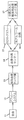
図7は、ブロック図の形で、献血者11から全血を採血し(全血)、上記に説明したようにアフェレーシス装置12を使用して濃縮タンパク質画分を採取するプロセスを例示している。アフェレーシスプロセスからの血漿タンパク質13は、任意選択で、血漿分画センター14に供給してもよく、また任意選択で他の採取物と共に貯留し、冷アルコール分画16(コーン分画としても知られている)又はクロマトグラフィー15などの公知の血漿分画プロセスを利用して、このような生成物をさらに分画又は濃縮することができる。その他の公知の分画プロセスを使用してもよい。このプロセスを使用してIVIG又は凝固因子などの高濃度の血漿タンパク質の輸液製品17を提供することができる。冷アルコール分画は、採取したアフェレーシスタンパク質生成物にこのタンパク質生成品を冷却しながらそれと同時にアルコールを添加することを含む。これによって、選別された血漿タンパク質が、任意の残留血漿又は他の選別されなかったタンパク質から沈殿する。クロマトグラフィーは、アフェレーシス血漿タンパク質を、固定相に通過させて、他のタンパク質及び残留している血漿と必要なタンパク質をさらに分離する方法を含む。これらのプロセスにより、さらに濃縮された、所望のタンパク質の生成物が生成される。このような生成品は、輸液製品として必要とされるまで凍結することができる。
FIG. 7 illustrates in block diagram form the process of collecting whole blood from donor 11 (whole blood) and collecting the concentrated protein fraction using
表2は、図4に関して上述したものと同様の、血漿濃縮器又は分離器205を持つ、アフェレーシスシステムにおける2回の運転のアッセイ結果を示す。HMW、すなわち高分子量は、出口206において分離器205から出る総タンパク質、アルブミン、又はlgG免疫グロブリンの量を示す。LMW、すなわち低分子量は、出口208においてアッセイされたタンパク質、アルブミン又はlgGの総量を示す。
Table 2 shows assay results of two runs in an apheresis system with a plasma concentrator or
表3は、図4に示された、血漿分離器を備えたアフェレーシスシステムにおける容量を基にしたタンパク質の予測値を示す。各運転ごとに、入口ポンプ1030の流速(入口)は示されている。また、203における流速に相当する、血漿採取ポンプ1066により決定される血漿流速も表に載せている。ライン93又は出口206における、HMW速度と称した流速も示されている。ポンプ1040で移送される導管又はライン963内の低分子の流速はLMWで示す。中空糸212の膜などの膜の全体にわたる圧力即ちトランス膜圧TMPも示されている。ポンプ比率は、HMWの流速(ここでは、高分子量のタンパク質が採取される。)に対する血漿採取の流速の比率である。量比率は、ある特定の時間の間に206を出る量に対する入口203に入る量である。この量は、単位時間に対する流速から容易に決定することができる。
Table 3 shows the predicted protein values based on volume in the apheresis system with plasma separator shown in FIG. For each run, the flow rate (inlet) of the
総タンパク質、アルブミン、lgGの測定濃度及びその平均値は、採取バッグ94から決定された際の値である。
The measured concentrations of total protein, albumin, and lgG and their average values are values determined from the
濃度比率及び量比率はほとんど一致を示している。実施例で示されるように、その違いは5%以下である。このデータから、タンパク質の濃度は量比率によって予測できることが理解し得る。 The concentration ratio and the quantity ratio are almost the same. As shown in the examples, the difference is 5% or less. From this data it can be seen that the protein concentration can be predicted by the quantity ratio.
タンパク質濃度を予測する方法は、ある時間の間に入口203を通過する量を測定するステップ、同じ時間の間に出口206での量を決定するステップを含むことができる。流入量は、ポンプ1066の回転数又は流速によって決定することができる。流出量は、バッグ94内にあるものの量の測定又はポンプ1040の回転数若しくは流速によって測定することができる。流出量に対する流入量を測定することによって、容量の比率が得られる。この比率は、バッグ94内に採取されるタンパク質の平均濃度比率として使用することができる。
The method of predicting protein concentration can include measuring the amount that passes through the
例えば、上記に示した主要値を使用して、
流入量−未採取量=流出量
流入量/流出量=流入量/流入量−流出量=量比率
決定した量比率は濃度比率に近似している。
For example, using the main values shown above,
Inflow amount-uncollected amount = outflow amount inflow amount / outflow amount = inflow amount / inflow amount-outflow amount = amount ratio The determined amount ratio approximates the concentration ratio.
前述のように、量比率は、単位時間に対する流速と関係している。出口206、208を通る流速と比較した、濃縮器205内への流速を含む、流速を選択し、これを使用して、最終の採取生成品のための特定のタンパク質濃度を選択することができる。
As described above, the quantity ratio is related to the flow rate per unit time. A flow rate, including the flow rate into the
本発明の範囲から逸脱することなく本発明の方法及び構造に様々な変更及び改変を加えることができることは当業者には理解されよう。したがって、本発明は、示されている特定の実施例に限定されるものではないことを理解されたい。それどころか、本発明は、改変及び変更が以下の特許請求項の範囲及びそれらと同等の範囲内である限りこれらの変更及び改変を含めるものである。 Those skilled in the art will recognize that various changes and modifications can be made to the method and structure of the present invention without departing from the scope of the invention. Accordingly, it should be understood that the invention is not limited to the specific embodiments shown. On the contrary, the invention is intended to cover these modifications and variations as long as the modifications and variations are within the scope of the following claims and their equivalents.
Claims (18)
該回転している分離容器352内で全血中の血漿と他の血液成分とを分離するステップと、
該分離した血漿を、該回転している分離容器352から血漿分離器205に供給するステップと、
該血漿を、血漿分離器205を使用して血漿タンパク質を含む少なくとも1つの画分に分離するステップと、
該少なくとも1つの画分を採取するステップと
を含む、全血から血漿画分を採取する方法であって、
前記採取するステップにおける前記少なくとも1つの画分の量(volume)に対する、前記供給するステップにおいて前記血漿分離器に供給された分離血漿の量(volume)の比率を求めて、量比(volume ratio)を決定するステップと、
該量比から、前記少なくとも1つの画分中の血漿タンパク質の濃縮率を予測するステップとをさらに含む、方法。 Rotating the separation vessel 352;
Separating plasma in whole blood from other blood components in the rotating separation vessel 352;
Supplying the separated plasma to the plasma separator 205 from the rotating separation vessel 352;
Separating the plasma into at least one fraction containing plasma proteins using a plasma separator 205;
Collecting a plasma fraction from whole blood, comprising collecting the at least one fraction ,
A ratio of the volume of separated plasma supplied to the plasma separator in the supplying step to the volume of the at least one fraction in the collecting step is determined. A step of determining
Predicting the concentration of plasma protein in the at least one fraction from the quantitative ratio.
特定の時間の間に前記血漿分離器に入る分離血漿の量を測定するステップと、
該特定の時間の間に、前記採取するステップにおいて前記血漿分離器から出る量を測定するステップとを含む、請求項1に記載の方法。 Determining the quantitative ratio comprises:
Measuring the amount of separated plasma entering the plasma separator during a specified time;
The during a particular time, and measuring the amount exiting the plasma separator in the step of collecting method of claim 1.
採取される血漿タンパク質から分離された前記血漿及び血漿タンパク質の量を測定するステップを含み、該ステップが、
前記血漿分離器から出る残留血漿及び残留血漿タンパク質の流速を決定するステップ及び
該残留血漿及び該残留血漿タンパク質の量を使用して、該分離された血漿タンパク質の濃度を予測するステップを含む、請求項2又は3に記載の方法。 Measuring the amount leaving the plasma separator,
Measuring the amount of said plasma and plasma protein separated from the plasma protein to be collected, said step comprising:
Determining the flow rate of residual plasma and residual plasma protein exiting the plasma separator and predicting the concentration of the separated plasma protein using the residual plasma and the amount of residual plasma protein. Item 4. The method according to Item 2 or 3 .
該ローター568に取り付けられ、該ローターと共に回転する分離容器352であって、該ローター568の回転中に血液がその中で血漿及び他の成分に分離される分離容器352と、
該分離容器352に流路として(fluidly)接続されて、該回転している分離容器352から、該分離血漿を受ける血漿分離器205と、
該血漿分離器205内に中空糸膜212を有し、少なくともいくつかの血漿タンパク質を該分離血漿から分離することができる膜212と、
該血漿分離器205から、該分離した血漿タンパク質を採取するための、該血漿分離器205に流路として接続されている採取容器94と
該血漿分離器205に供給された分離血漿の量を決定する手段1066と、
該採取された血漿タンパク質画分の量を決定する手段1040、1040aと、
該採取された血漿タンパク質画分の量に対する、該血漿分離器205に供給された分離血漿の量の比を調整し、これにより該血漿分離器205での血漿タンパク質の濃縮率を調整する手段6、1066、1040、1040aとを備える、アフェレーシス血漿分離システム。 Rotor 568,
A separation vessel 352 attached to and rotating with the rotor 568, wherein blood is separated into plasma and other components therein during rotation of the rotor 568;
A plasma separator 205 fluidly connected to the separation vessel 352 and receiving the separated plasma from the rotating separation vessel 352;
A membrane 212 having a hollow fiber membrane 212 in the plasma separator 205 and capable of separating at least some plasma proteins from the separated plasma;
A collection container 94 connected as a flow path to the plasma separator 205 for collecting the separated plasma protein from the plasma separator 205;
Means 1066 for determining the amount of separated plasma supplied to the plasma separator 205;
Means 1040, 1040a for determining the amount of the collected plasma protein fraction;
Means 6 for adjusting the ratio of the amount of separated plasma supplied to the plasma separator 205 to the amount of the collected plasma protein fraction, thereby adjusting the concentration ratio of the plasma protein in the plasma separator 205 An apheresis plasma separation system comprising: 1066, 1040, 1040a .
Applications Claiming Priority (11)
| Application Number | Priority Date | Filing Date | Title |
|---|---|---|---|
| US8815408P | 2008-08-12 | 2008-08-12 | |
| US61/088,154 | 2008-08-12 | ||
| US9389208P | 2008-09-03 | 2008-09-03 | |
| US61/093,892 | 2008-09-03 | ||
| US9759808P | 2008-09-17 | 2008-09-17 | |
| US61/097,598 | 2008-09-17 | ||
| US12076308P | 2008-12-08 | 2008-12-08 | |
| US61/120,763 | 2008-12-08 | ||
| US12/429,266 US8123713B2 (en) | 2008-08-12 | 2009-04-24 | System and method for collecting plasma protein fractions from separated blood components |
| US12/429,266 | 2009-04-24 | ||
| PCT/US2009/048087 WO2010019317A2 (en) | 2008-08-12 | 2009-06-22 | System and method for collecting plasma protein fractions from separated blood components |
Related Child Applications (1)
| Application Number | Title | Priority Date | Filing Date |
|---|---|---|---|
| JP2014092874A Division JP2014168701A (en) | 2008-08-12 | 2014-04-28 | System and method for collecting plasma protein fraction from separated blood components |
Publications (3)
| Publication Number | Publication Date |
|---|---|
| JP2011530384A JP2011530384A (en) | 2011-12-22 |
| JP2011530384A5 JP2011530384A5 (en) | 2012-08-09 |
| JP5538390B2 true JP5538390B2 (en) | 2014-07-02 |
Family
ID=41669545
Family Applications (2)
| Application Number | Title | Priority Date | Filing Date |
|---|---|---|---|
| JP2011523014A Active JP5538390B2 (en) | 2008-08-12 | 2009-06-22 | System and method for collecting plasma protein fractions from separated blood components |
| JP2014092874A Pending JP2014168701A (en) | 2008-08-12 | 2014-04-28 | System and method for collecting plasma protein fraction from separated blood components |
Family Applications After (1)
| Application Number | Title | Priority Date | Filing Date |
|---|---|---|---|
| JP2014092874A Pending JP2014168701A (en) | 2008-08-12 | 2014-04-28 | System and method for collecting plasma protein fraction from separated blood components |
Country Status (4)
| Country | Link |
|---|---|
| US (2) | US8123713B2 (en) |
| EP (1) | EP2313771B1 (en) |
| JP (2) | JP5538390B2 (en) |
| WO (1) | WO2010019317A2 (en) |
Families Citing this family (22)
| Publication number | Priority date | Publication date | Assignee | Title |
|---|---|---|---|---|
| US8123713B2 (en) * | 2008-08-12 | 2012-02-28 | Caridian Bct, Inc. | System and method for collecting plasma protein fractions from separated blood components |
| US9446354B2 (en) | 2010-08-25 | 2016-09-20 | Repligen Corporation | Device, system and process for modification or concentration of cell-depleted fluid |
| WO2012141697A1 (en) * | 2011-04-13 | 2012-10-18 | Fenwal, Inc. | Systems and methods for use and control of an automated separator with adsorption columns |
| WO2013025415A1 (en) | 2011-08-12 | 2013-02-21 | Terumo Bct, Inc. | System for blood separation with replacement fluid apparatus and method |
| US9327296B2 (en) | 2012-01-27 | 2016-05-03 | Fenwal, Inc. | Fluid separation chambers for fluid processing systems |
| WO2013152253A1 (en) | 2012-04-05 | 2013-10-10 | Terumo Bct, Inc. | Syestem and method for collecting and treating plasma protein fractions |
| US9057055B2 (en) | 2012-12-05 | 2015-06-16 | The Royal Institution For The Advancement Of Learning/Mcgill University | Method of obtaining circulating cancer cell populations |
| WO2014195252A2 (en) * | 2013-06-03 | 2014-12-11 | Avance Medical Sàrl | Extemporaneous preparation of autologous fibrin |
| CN106470676A (en) * | 2014-05-08 | 2017-03-01 | 德克萨斯大学系统董事会 | Method and composition for non-cell toxicity stem cell transplantation |
| WO2016019113A1 (en) * | 2014-08-01 | 2016-02-04 | Siemens Healthcare Diagnostics Inc. | Vacuum-assisted plasma separation |
| US10207044B2 (en) | 2015-07-29 | 2019-02-19 | Fenwal, Inc. | Five-port blood separation chamber and methods of using the same |
| AU2017278303B2 (en) * | 2016-06-10 | 2022-08-18 | Repligen Corporation | Chromatography column packing medium recovery |
| CA3066361A1 (en) | 2017-06-07 | 2018-12-13 | Shifamed Holdings, Llc | Intravascular fluid movement devices, systems, and methods of use |
| CN107583120B (en) * | 2017-09-20 | 2024-05-14 | 中南大学湘雅二医院 | Plasma exchange dialysis adsorption system |
| EP3710076B1 (en) | 2017-11-13 | 2023-12-27 | Shifamed Holdings, LLC | Intravascular fluid movement devices, systems, and methods of use |
| WO2019188501A1 (en) * | 2018-03-26 | 2019-10-03 | Terumo Kabushiki Kaisha | Biological component treatment cassette and biological component treatment system |
| JP2022540616A (en) | 2019-07-12 | 2022-09-16 | シファメド・ホールディングス・エルエルシー | Intravascular blood pump and methods of manufacture and use |
| US11654275B2 (en) | 2019-07-22 | 2023-05-23 | Shifamed Holdings, Llc | Intravascular blood pumps with struts and methods of use and manufacture |
| US11724089B2 (en) | 2019-09-25 | 2023-08-15 | Shifamed Holdings, Llc | Intravascular blood pump systems and methods of use and control thereof |
| RU199624U1 (en) * | 2020-03-20 | 2020-09-10 | Федеральное государственное бюджетное образовательное учреждение высшего образования "Самарский государственный медицинский университет" Министерства здравоохранения Российской Федерации | ELECTROPHORETIC CHIP FOR DETERMINING BLOOD PROTEIN FRACTIONS |
| WO2022120270A1 (en) * | 2020-12-04 | 2022-06-09 | Shifamed Holdings, Llc | Catheter blood pumps and external fluid control consoles |
| CA3232327A1 (en) * | 2021-10-21 | 2023-04-27 | Siemens Healthcare Diagnostics Inc. | Fluidic tubing assembly for blood analyzer |
Family Cites Families (65)
| Publication number | Priority date | Publication date | Assignee | Title |
|---|---|---|---|---|
| CA1131527A (en) * | 1977-10-18 | 1982-09-14 | James H. Devries | Monitor and fluid circuit assembly |
| US4276140A (en) * | 1980-01-10 | 1981-06-30 | Ionics Inc. | Electrodialysis apparatus and process for fractionating protein mixtures |
| US4351710A (en) * | 1980-01-10 | 1982-09-28 | Ionics, Incorporated | Fractionation of protein mixtures |
| US4619639A (en) * | 1980-02-05 | 1986-10-28 | Asahi Medical Co., Ltd. | Method and apparatus for low pressure filtration of plasma from blood |
| US4350594A (en) * | 1980-04-16 | 1982-09-21 | Kuraray Co., Ltd. | Blood purification using plural ultrafiltration stages |
| US4350156A (en) * | 1980-05-29 | 1982-09-21 | Japan Foundation For Artificial Organs | Method and apparatus for on-line filtration removal of macromolecules from a physiological fluid |
| US4746436A (en) * | 1981-06-25 | 1988-05-24 | Baxter Travenol Laboratories, Inc. | Membrane plasmapheresis apparatus and process which utilize a flexible wall to variably restrict the flow of plasma filtrate and thereby stabilize transmembrane pressure |
| FR2519555A1 (en) * | 1982-01-11 | 1983-07-18 | Rhone Poulenc Sa | APPARATUS AND METHOD FOR ALTERNATIVE PLASMAPHERESE WITH MEMBRANE APPARATUS |
| JPS598967A (en) * | 1982-07-08 | 1984-01-18 | 日機装株式会社 | Continuous blood treating apparatus |
| JPS59501537A (en) * | 1982-08-24 | 1984-08-30 | バクスタ−、トラベノ−ル、ラボラトリ−ズ インコ−ポレイテッド | Increased Yield Blood Component Collection System and Method |
| WO1984000905A1 (en) * | 1982-08-24 | 1984-03-15 | Baxter Travenol Lab | Blood component collection systems and methods |
| JPS6036061A (en) * | 1983-08-08 | 1985-02-25 | 鐘淵化学工業株式会社 | Blood purifying apparatus |
| US4898675A (en) * | 1983-08-15 | 1990-02-06 | Lavender Ardis R | System and method for continuously fractionating blood in situ |
| DE3570188D1 (en) * | 1984-02-24 | 1989-06-22 | Kuraray Co | Apparatus for the treatment of plasma |
| JPS60179065A (en) * | 1984-02-24 | 1985-09-12 | 株式会社クラレ | Blood treating apparatus |
| US4776964A (en) * | 1984-08-24 | 1988-10-11 | William F. McLaughlin | Closed hemapheresis system and method |
| US4780205A (en) * | 1984-10-30 | 1988-10-25 | Teijin Limited | Permselective hollow fiber membrane, process for the preparation thereof, method and apparatus for plasma components separation |
| JPS61193668A (en) * | 1985-02-21 | 1986-08-28 | 株式会社クラレ | Serum treatment apparatus |
| US4806247A (en) * | 1985-04-12 | 1989-02-21 | Baxter International Inc. | Plasmapheresis system and method |
| US4713176A (en) * | 1985-04-12 | 1987-12-15 | Hemascience Laboratories, Inc. | Plasmapheresis system and method |
| GB8513240D0 (en) * | 1985-05-24 | 1985-06-26 | Metal Box Plc | Spin welding machine |
| JPS6247367A (en) * | 1985-08-24 | 1987-03-02 | 株式会社 日本メデイカル・サプライ | Blood concentrator |
| US4721564A (en) | 1985-10-22 | 1988-01-26 | Kuraray Co., Ltd. | Apparatus for the filtration of plasma from blood |
| US4871462A (en) * | 1985-12-23 | 1989-10-03 | Haemonetics Corporation | Enhanced separation of blood components |
| US4728430A (en) * | 1986-02-10 | 1988-03-01 | Millipore Corporation | Diafiltration method |
| US4789482A (en) | 1986-02-10 | 1988-12-06 | Millipore Corporation | Method for separating liquid compositions on the basis of molecular weight |
| JPS63105770A (en) | 1986-10-23 | 1988-05-11 | 鐘淵化学工業株式会社 | Plasma component separating membrane |
| JPS63111877A (en) * | 1986-10-29 | 1988-05-17 | 株式会社ニツシヨ− | Plasma sampling apparatus and method |
| US4789842A (en) * | 1987-11-23 | 1988-12-06 | Jiri Naxera | Composite transistor device with over-current protection |
| DE68902698C5 (en) * | 1988-06-23 | 2005-07-14 | Asahi Medical Co. Ltd. | Method for separating blood into blood components and unit for separating blood components. |
| US5008012A (en) * | 1989-05-25 | 1991-04-16 | Asahi Medical Co., Ltd. | Compact plasma separator and an apparatus containing the same |
| US5141490A (en) * | 1989-06-25 | 1992-08-25 | Terumo Kabushiki Kaisha | Single-needle type plasma separation apparatus and plasma collection apparatus |
| IT1244805B (en) * | 1990-11-22 | 1994-09-05 | Roerig Farmaceutici Italiana S | SINGLE NEEDLE PLASMAFERESIS EXTRA-BODY CIRCUIT |
| DE69212088T2 (en) * | 1991-03-26 | 1996-11-21 | Otsuka Pharma Co Ltd | METHOD AND DEVICE FOR FILTERING PLASMA |
| US5217618A (en) * | 1991-08-26 | 1993-06-08 | Terumo Kabushiki Kaisha | Plasma purification treatment |
| AU663250B2 (en) * | 1993-01-28 | 1995-09-28 | Otsuka Pharmaceutical Factory, Inc. | Secondary filter cleaning method in blood plasma filtration method |
| AUPN858596A0 (en) * | 1996-03-08 | 1996-04-04 | Csl Limited | Filtration of plasma precipitates using cellulose filter aid |
| US5868936A (en) * | 1996-06-20 | 1999-02-09 | Baxter International Inc. | Affinity membrane system and method of using same |
| US5954971A (en) * | 1997-01-07 | 1999-09-21 | Haemonetics Corporation | Pumped-filter blood-processing apparatus and methods |
| US6251295B1 (en) * | 1998-01-08 | 2001-06-26 | Nexell Therapeutics Inc. | Method for recirculation washing of blood cells |
| US6669905B1 (en) * | 1998-05-21 | 2003-12-30 | Baxter International Inc. | Systems and methods for collecting plasma that is free or virtually free of cellular blood species |
| US6277337B1 (en) * | 1998-07-21 | 2001-08-21 | Gambro, Inc. | Method and apparatus for inactivation of biological contaminants using photosensitizers |
| DE19904088A1 (en) * | 1999-02-02 | 2000-09-07 | Fressenius Hemocare Gmbh | Tubing set for a cell separator for separating blood into its components and method for separating blood into its components |
| US6730054B2 (en) * | 1999-10-16 | 2004-05-04 | Baxter International Inc. | Blood collection systems and methods that derive estimated effects upon the donor's blood volume and hematocrit |
| BR0014802A (en) * | 1999-10-16 | 2003-11-11 | Baxter Int | Automated collection systems and methods for obtaining whole blood red blood cells, platelets and plasma |
| US7470245B2 (en) * | 2000-02-02 | 2008-12-30 | Xepmed, Inc. | Extracorporeal pathogen reduction system |
| JP3936142B2 (en) * | 2000-02-04 | 2007-06-27 | テルモ株式会社 | Blood component collection device |
| AU2001232053A1 (en) | 2000-02-11 | 2001-08-20 | Allied Therapeutics Limited | System for the extracorporeal treatment of blood |
| WO2001066172A2 (en) * | 2000-03-09 | 2001-09-13 | Gambro, Inc. | Extracorporeal blood processing method and apparatus |
| DE20014311U1 (en) * | 2000-08-15 | 2001-02-15 | Heim Medizintechnik Gmbh | Filter arrangement for separating blood into plasma and cellular components |
| US6808503B2 (en) * | 2001-03-06 | 2004-10-26 | Baxter International Inc. | Automated system and method for pre-surgical blood donation and fluid replacement |
| US6849183B2 (en) * | 2002-08-13 | 2005-02-01 | Transvivo, Inc. | Method and apparatus for therapeutic apheresis |
| US7481936B2 (en) * | 2001-10-17 | 2009-01-27 | Transvivo Inc. | Method and apparatus for patient fluid management |
| US20030205538A1 (en) * | 2002-05-03 | 2003-11-06 | Randel Dorian | Methods and apparatus for isolating platelets from blood |
| US20060129082A1 (en) * | 2002-08-13 | 2006-06-15 | Jacek Rozga | Selective plasma exchange therapy |
| CA2498244C (en) * | 2002-09-12 | 2012-03-06 | Teruhiko Oishi | Plasma purification membrane and plasma purification system |
| US7291269B2 (en) * | 2003-03-17 | 2007-11-06 | Gambro Lundia Ab | Apparatus and process for extracorporeal treatment of blood with selective extraction of solutes |
| JP4283013B2 (en) * | 2003-03-18 | 2009-06-24 | テルモ株式会社 | Blood component collection circuit |
| ITPD20030076A1 (en) * | 2003-04-16 | 2003-07-15 | Federico Nalesso | PLASMA MACHINE COMBINED PLASMA PURIFICATION ADSORPTION-PERFUSION BY USING A THREE-COMPARTMENTAL DIALIZER |
| JP4368810B2 (en) * | 2005-01-28 | 2009-11-18 | テルモ株式会社 | Filter device and blood component collection device |
| US20060226086A1 (en) * | 2005-04-08 | 2006-10-12 | Robinson Thomas C | Centrifuge for blood processing systems |
| JP4848143B2 (en) * | 2005-06-17 | 2011-12-28 | テルモ株式会社 | Blood component collection device |
| JP2007215569A (en) * | 2006-02-14 | 2007-08-30 | Asahi Kasei Medical Co Ltd | Plasma component separator and blood purifying apparatus by double filtration |
| KR100843339B1 (en) * | 2006-12-07 | 2008-07-03 | 한국전자통신연구원 | Serum separator using microchannel for separating serum from whole blood and the method of separating serum by the same |
| US8123713B2 (en) * | 2008-08-12 | 2012-02-28 | Caridian Bct, Inc. | System and method for collecting plasma protein fractions from separated blood components |
-
2009
- 2009-04-24 US US12/429,266 patent/US8123713B2/en active Active
- 2009-06-22 EP EP09807017.0A patent/EP2313771B1/en active Active
- 2009-06-22 WO PCT/US2009/048087 patent/WO2010019317A2/en active Application Filing
- 2009-06-22 JP JP2011523014A patent/JP5538390B2/en active Active
-
2012
- 2012-02-21 US US13/400,811 patent/US20120145619A1/en not_active Abandoned
-
2014
- 2014-04-28 JP JP2014092874A patent/JP2014168701A/en active Pending
Also Published As
| Publication number | Publication date |
|---|---|
| JP2014168701A (en) | 2014-09-18 |
| US20120145619A1 (en) | 2012-06-14 |
| WO2010019317A3 (en) | 2010-04-01 |
| US8123713B2 (en) | 2012-02-28 |
| WO2010019317A2 (en) | 2010-02-18 |
| US20100042037A1 (en) | 2010-02-18 |
| JP2011530384A (en) | 2011-12-22 |
| EP2313771A4 (en) | 2017-10-25 |
| EP2313771A2 (en) | 2011-04-27 |
| EP2313771B1 (en) | 2020-06-17 |
Similar Documents
| Publication | Publication Date | Title |
|---|---|---|
| JP5538390B2 (en) | System and method for collecting plasma protein fractions from separated blood components | |
| US7052606B2 (en) | Methods and apparatus for leukoreduction of red blood cells | |
| JP5667211B2 (en) | Apparatus for extracting platelets with low plasma carryover | |
| US8202240B2 (en) | System and method for collecting plasma protein fractions from separated blood components | |
| US20130264288A1 (en) | System and Method For Collecting And Treating Plasma Protein Fractions | |
| US20070118063A1 (en) | Method and Apparatus for Leukoreduction of Red Blood Cells | |
| EP2515966B1 (en) | Methods and apparatus for collection of filtered blood components, in particular red blood cells | |
| JP5215412B2 (en) | Apparatus for the controlled addition of solvents to blood components | |
| EP2695625A2 (en) | Methods for automated blood prime |
Legal Events
| Date | Code | Title | Description |
|---|---|---|---|
| A521 | Request for written amendment filed |
Free format text: JAPANESE INTERMEDIATE CODE: A523 Effective date: 20120619 |
|
| A621 | Written request for application examination |
Free format text: JAPANESE INTERMEDIATE CODE: A621 Effective date: 20120619 |
|
| A131 | Notification of reasons for refusal |
Free format text: JAPANESE INTERMEDIATE CODE: A131 Effective date: 20130705 |
|
| A601 | Written request for extension of time |
Free format text: JAPANESE INTERMEDIATE CODE: A601 Effective date: 20131001 |
|
| A602 | Written permission of extension of time |
Free format text: JAPANESE INTERMEDIATE CODE: A602 Effective date: 20131008 |
|
| A601 | Written request for extension of time |
Free format text: JAPANESE INTERMEDIATE CODE: A601 Effective date: 20131101 |
|
| A602 | Written permission of extension of time |
Free format text: JAPANESE INTERMEDIATE CODE: A602 Effective date: 20131111 |
|
| A521 | Request for written amendment filed |
Free format text: JAPANESE INTERMEDIATE CODE: A523 Effective date: 20131128 |
|
| TRDD | Decision of grant or rejection written | ||
| A01 | Written decision to grant a patent or to grant a registration (utility model) |
Free format text: JAPANESE INTERMEDIATE CODE: A01 Effective date: 20140411 |
|
| R150 | Certificate of patent or registration of utility model |
Ref document number: 5538390 Country of ref document: JP Free format text: JAPANESE INTERMEDIATE CODE: R150 |
|
| A61 | First payment of annual fees (during grant procedure) |
Free format text: JAPANESE INTERMEDIATE CODE: A61 Effective date: 20140428 |
|
| R250 | Receipt of annual fees |
Free format text: JAPANESE INTERMEDIATE CODE: R250 |
|
| R250 | Receipt of annual fees |
Free format text: JAPANESE INTERMEDIATE CODE: R250 |
|
| R250 | Receipt of annual fees |
Free format text: JAPANESE INTERMEDIATE CODE: R250 |
|
| R250 | Receipt of annual fees |
Free format text: JAPANESE INTERMEDIATE CODE: R250 |
|
| R250 | Receipt of annual fees |
Free format text: JAPANESE INTERMEDIATE CODE: R250 |
|
| R250 | Receipt of annual fees |
Free format text: JAPANESE INTERMEDIATE CODE: R250 |
|
| R250 | Receipt of annual fees |
Free format text: JAPANESE INTERMEDIATE CODE: R250 |
|
| R250 | Receipt of annual fees |
Free format text: JAPANESE INTERMEDIATE CODE: R250 |