JP5537117B2 - Paper sheet handling equipment - Google Patents
Paper sheet handling equipment Download PDFInfo
- Publication number
- JP5537117B2 JP5537117B2 JP2009245957A JP2009245957A JP5537117B2 JP 5537117 B2 JP5537117 B2 JP 5537117B2 JP 2009245957 A JP2009245957 A JP 2009245957A JP 2009245957 A JP2009245957 A JP 2009245957A JP 5537117 B2 JP5537117 B2 JP 5537117B2
- Authority
- JP
- Japan
- Prior art keywords
- driven
- frame
- paper sheet
- discrimination
- inclined surface
- Prior art date
- Legal status (The legal status is an assumption and is not a legal conclusion. Google has not performed a legal analysis and makes no representation as to the accuracy of the status listed.)
- Active
Links
Images


Classifications
-
- G—PHYSICS
- G07—CHECKING-DEVICES
- G07D—HANDLING OF COINS OR VALUABLE PAPERS, e.g. TESTING, SORTING BY DENOMINATIONS, COUNTING, DISPENSING, CHANGING OR DEPOSITING
- G07D11/00—Devices accepting coins; Devices accepting, dispensing, sorting or counting valuable papers
- G07D11/10—Mechanical details
- G07D11/12—Containers for valuable papers
-
- G—PHYSICS
- G07—CHECKING-DEVICES
- G07D—HANDLING OF COINS OR VALUABLE PAPERS, e.g. TESTING, SORTING BY DENOMINATIONS, COUNTING, DISPENSING, CHANGING OR DEPOSITING
- G07D11/00—Devices accepting coins; Devices accepting, dispensing, sorting or counting valuable papers
- G07D11/10—Mechanical details
- G07D11/14—Inlet or outlet ports
-
- G—PHYSICS
- G07—CHECKING-DEVICES
- G07D—HANDLING OF COINS OR VALUABLE PAPERS, e.g. TESTING, SORTING BY DENOMINATIONS, COUNTING, DISPENSING, CHANGING OR DEPOSITING
- G07D11/00—Devices accepting coins; Devices accepting, dispensing, sorting or counting valuable papers
- G07D11/40—Device architecture, e.g. modular construction
Description
本発明は、鑑別装置を着脱自在に取り付けられる紙葉類取扱装置に関連する。 The present invention relates to a paper sheet handling device to which a discrimination device is detachably attached.
例えば、自動販売機、両替機、現金自動支払機、自動預金機、ゲーム機等に搭載される下記特許文献1に開示される紙幣取扱装置を図23に示す。図示のように、紙幣取扱装置(100)は、フレーム(111)に固定されて紙幣の真贋を判定する鑑別装置(101)と、鑑別装置(101)から供給される紙幣を紙幣収納部(104)に収納する収納装置(103)とを備える。鑑別装置(101)は、鑑別した紙幣を搬送通路(107)に沿って収納装置(103)に移送する搬送装置(102)を備える。収納装置(103)は、紙幣取扱装置のフレーム(111)に着脱自在に取り付けられ、鑑別装置(101)から搬送される紙幣を収納する紙幣収納部(104)と、収納装置(103)に搬送される紙幣を紙幣収納部(104)に押込む押込装置(105)とを有する。
For example, FIG. 23 shows a banknote handling apparatus disclosed in the following
収納装置(103)のケース(106)内に形成される収容空間(108)内に押込装置(105)が収納装置(103)に対して着脱可能に配置される。搬送装置(102)に設けられる搬送通路出口(109)は、押込装置(105)に設けられるスリット状の紙幣取入口(110)に接続される。フレーム(111)に収納装置(103)を取り付けるとき、押込装置(105)の従動歯車(113)は、搬送装置(102)に設けられる駆動歯車(112)に自動的に駆動連結される。 The push-in device (105) is detachably arranged with respect to the storage device (103) in the storage space (108) formed in the case (106) of the storage device (103). A conveyance passage outlet (109) provided in the conveyance device (102) is connected to a slit-shaped banknote intake (110) provided in the pushing device (105). When the storage device (103) is attached to the frame (111), the driven gear (113) of the pushing device (105) is automatically driven and connected to the drive gear (112) provided in the transport device (102).
鑑別装置(101)により真正と判断される紙幣は、搬送装置(102)により搬送通路出口(109)から排出され、ケース(106)の紙幣取入口(110)から収容空間(108)内に搬送される。このとき、搬送装置(102)の図示しないモータが逆転されると、搬送装置(102)の駆動歯車(112)に駆動接続される従動歯車(113)は、駆動歯車(112)により逆転されるため、押込装置(105)が駆動されて、収容空間(108)内の紙幣を紙幣収納部(104)内に押込むことができる。従動歯車(113)の正転時に、押込装置(105)は、図示の引込位置に戻される。 The banknote judged to be authentic by the discrimination device (101) is discharged from the transport passage outlet (109) by the transport device (102) and transported from the banknote inlet (110) of the case (106) into the accommodation space (108). Is done. At this time, when a motor (not shown) of the conveying device (102) is reversed, the driven gear (113) that is drivingly connected to the driving gear (112) of the conveying device (102) is reversed by the driving gear (112). Therefore, the pushing device (105) is driven, and the banknote in the accommodation space (108) can be pushed into the banknote storage part (104). During the forward rotation of the driven gear (113), the pushing device (105) is returned to the drawing position shown.
従来の前記紙幣取扱装置では、フレーム(111)に収納装置(103)を装着するときに、フレーム(111)に固定された搬送装置(102)の駆動歯車(112)に押込装置(105)の従動歯車(113)を自動的に互いに駆動連結できる。この駆動連結構造では、搬送装置(102)の駆動歯車(112)に押込装置(105)の従動歯車(113)との連結時の衝撃を緩衝する緩衝構造が設けられる。 In the conventional bill handling device, when the storage device (103) is mounted on the frame (111), the push gear (105) is inserted into the drive gear (112) of the transport device (102) fixed to the frame (111). The driven gears (113) can be automatically connected to each other. In this drive connection structure, a buffer structure for buffering an impact when the drive gear (112) of the transport device (102) is connected to the driven gear (113) of the pushing device (105) is provided.
フレーム(111)に着脱可能に鑑別装置(101)を装着する従来の異なる滑動連結構造の断面図を図24に示す。図示のように、鑑別装置(101)を嵌合する鈎状突起(115)がフレーム(111)上に形成され、滑動可能に鈎状突起(115)に係合される開口部(117)が鑑別装置(101)の底面に形成される。鈎状突起(115)と開口部(117)との係合によりフレーム(111)に着脱自在に鑑別装置(101)を取り付ける滑動連結構造(116)が形成される。しかしながら、この滑動連結構造(116)では、フレーム(111)に鑑別装置(101)を装着するとき、鑑別装置(101)の搬送装置(102)の駆動歯車(112)が鈎状突起(115)に衝突して、駆動歯車(112)が機械的損傷を受ける危険がある。また、鈎状突起(115)と鑑別装置(101)とで構成される滑動連結構造(116)の分だけ紙幣取扱装置の高さが増加する難点がある。更に、紙幣取扱装置の寸法が規格により制限されるため、鑑別装置(101)及びフレーム(111)の大きさの分だけ収納装置(103)の収容量を制限せざるをえず、従来の収納装置(103)では、収容空間(108)内に収納できないサイズの長い紙幣も存在した。 FIG. 24 shows a cross-sectional view of a different conventional sliding connection structure in which the discrimination device (101) is detachably attached to the frame (111). As shown in the figure, a hook-like protrusion (115) for fitting the discrimination device (101) is formed on the frame (111), and an opening (117) that is slidably engaged with the hook-like protrusion (115) is formed. It is formed on the bottom surface of the discrimination device (101). A sliding connection structure (116) for attaching the discrimination device (101) to the frame (111) in a detachable manner is formed by engagement between the hook-shaped protrusion (115) and the opening (117). However, in this sliding connection structure (116), when the identification device (101) is attached to the frame (111), the drive gear (112) of the conveying device (102) of the identification device (101) is the hook-shaped protrusion (115). There is a risk that the drive gear (112) may be mechanically damaged. In addition, there is a problem that the height of the bill handling device increases by the amount of the sliding connection structure (116) constituted by the hook-shaped protrusion (115) and the discrimination device (101). Furthermore, since the size of the bill handling device is limited by the standard, the storage capacity of the storage device (103) must be limited by the size of the discrimination device (101) and the frame (111), and the conventional storage In the device (103), there were long bills that could not be stored in the storage space (108).
従って、本発明は、鑑別装置を容易に着脱自在に取り付けられる紙葉類取扱装置を提供することを目的とする。また、本発明は、紙葉類取扱装置のフレームに鑑別装置を着脱自在に取り付けかつより大きなサイズの紙葉類を収納できる収納装置を有する紙幣取扱装置を提供することを目的とする。更に、鑑別装置内の搬送装置を損傷せずに、搬送装置を収納装置に駆動接続できる紙葉類取扱装置を提供することを目的とする。 Therefore, an object of the present invention is to provide a paper sheet handling device to which a discrimination device can be easily and detachably attached. Another object of the present invention is to provide a banknote handling apparatus having a storage device that can detachably attach a discrimination device to a frame of a paper sheet handling apparatus and can store larger size paper sheets. Furthermore, it aims at providing the paper sheet handling apparatus which can drive-connect a conveyance apparatus to a storage apparatus, without damaging the conveyance apparatus in a discrimination apparatus.
本発明による紙葉類取扱装置は、一対の側壁(41)及び一対の側壁(41)間に架橋されたブラケット(7)を有するフレーム(1)と、底面(52)及び底面(52)から下方に突出する駆動歯車(26)を有する搬送装置(102)を備えかつフレーム(1)に着脱可能に取り付けられる鑑別装置(2)と、紙葉収納部(104)、収容空間(108)、収容空間(108)内に配置されて鑑別装置(2)から搬送される紙葉を紙葉収納部(104)内に押し込む押込装置(105)、押込装置(105)を駆動する従動歯車(27)を有しかつフレーム(1)に取り付けられる収納装置(3)と、鑑別装置(2)をフレーム(1)に着脱可能に取り付ける連結装置(4)とを備える。連結装置(4)は、フレーム(1)の側壁(41)及び鑑別装置(2)の側壁(51)の一方に形成されるカム案内部(5)と、フレーム(1)の側壁(41)及び鑑別装置(2)の側壁(51)の他方に形成されかつカム案内部(5)に係止する従動部(6)とを有する。カム案内部(5)は、ブラケット(7)から離間してかつ搬送装置(102)の駆動歯車(26)をブラケット(7)に接触させずに、従動部(6)の移動を案内して鑑別装置(2)を水平に移動させる遠位通路(10)と、遠位通路(10)に接続されかつ遠位通路(10)を通過した従動部(6)を収納装置(3)に向って斜めに移動させる接近通路(11)と、接近通路(11)に接続されかつ接近通路(11)を通過した従動部(6)を鑑別装置(2)の装着位置まで水平に移動させて搬送装置(102)の駆動歯車(26)を収納装置(3)の従動歯車(27)に駆動連結させる係止通路(12)とを有する。
本発明による別の紙葉類取扱装置は、一対の側壁(41)及び一対の側壁(41)間に架橋されたブラケット(7)を有するフレーム(1)と、搬送装置(102)を備えかつフレーム(1)に着脱可能に取り付けられる鑑別装置(2)と、鑑別装置(2)をフレーム(1)に着脱可能に取り付ける連結装置(4)と、フレーム(1)に取り付けられて鑑別装置(2)から搬送される紙葉を収納する収納装置(3)とを備える。鑑別装置(2)は、鑑別装置(2)内で紙葉を搬送する搬送装置(102)により駆動される駆動歯車(26)と、鑑別装置(2)の底面(52)から突出する複数の防御突起(58)とを有する。収納装置(3)は、鑑別装置(2)からの紙葉が通過する紙葉取入口(63)と、紙葉取入口(63)を通過する紙葉を収納する収容空間(108)と、収容空間(108)内の紙葉を紙葉収納部(104)内に押込む押込装置(105)と、押込装置(105)を駆動する従動歯車(27)と、収納装置(3)の上面(62)に形成される複数の係合溝(64)とを有する。連結装置(4)は、フレーム(1)の側壁(41)及び鑑別装置(2)の側壁(51)の一方に形成されるカム案内部(5)と、フレーム(1)の側壁(41)及び鑑別装置(2)の側壁(51)の他方に形成されかつカム案内部(5)に係止する従動部(6)とを有する。鑑別装置(2)の駆動歯車(26)は、複数の防御突起(58)間に配置され、押込装置(105)の従動歯車(27)は、複数の係合溝(64)間に配置される。鑑別装置(2)がフレーム(1)の取付位置に移動されるとき、搬送装置(102)の駆動歯車(26)が押込装置(105)の従動歯車(27)に駆動連結されると共に、複数の防御突起(58)が収納装置(3)の係合溝(64)内に嵌合され、搬送装置(102)により従動歯車(27)を回転して押込装置(105)を作動する。
本発明のように、フレーム(1)の側壁(41)と鑑別装置(2)の側壁(51)との間に着脱可能な連結装置(4)を設けると、カム案内部(5)と従動部(6)との間に付加的構成部品を設ける必要がない点で有利である。また、本実施の形態では、カム案内部(5)は、従動部(6)を介してブラケット(7)から離間して鑑別装置(2)の搬送装置(102)の移動を案内する遠位通路(10)と、遠位通路(10)を通過した鑑別装置(2)をフレーム(1)の取付位置に案内する接近通路(11)とを備える。遠位通路(10)に沿う従動部(6)の移動により、鑑別装置(2)の搬送装置(102)をブラケット(7)に接触させずに、遠位通路(10)に沿って従動部(6)を案内できるので、搬送装置(102)に機械的損傷を回避して、鑑別装置(2)をフレーム(1)に係合することができる。
The paper sheet handling apparatus according to the present invention includes a frame (1) having a pair of side walls (41) and a bracket (7) bridged between the pair of side walls (41), a bottom surface (52), and a bottom surface (52). A discrimination device (2) having a conveying device (102) having a drive gear (26) protruding downward and detachably attached to the frame (1), a paper sheet storage portion (104), a storage space (108), A pushing device (105) for pushing a paper sheet placed in the accommodation space (108) and conveyed from the discrimination device (2) into the paper sheet storage unit (104), a driven gear (27) for driving the pushing device (105) ) And attached to the frame (1) and a connecting device (4) for detachably attaching the discrimination device (2) to the frame (1). The connecting device (4) includes a cam guide (5) formed on one of the side wall (41) of the frame (1) and the side wall (51) of the discrimination device (2), and the side wall (41) of the frame (1). And a driven portion (6) formed on the other side wall (51) of the discrimination device (2) and engaged with the cam guide portion (5). The cam guide portion (5) guides the movement of the driven portion (6) while being separated from the bracket (7) and without bringing the drive gear (26) of the transport device (102) into contact with the bracket (7). The distal passage (10) for horizontally moving the identification device (2) and the follower (6) connected to the distal passage (10) and passing through the distal passage (10) are directed toward the storage device (3). And move the approaching passage (11) that moves diagonally and the driven part (6) connected to the approaching passage (11) and passing through the approaching passage (11) horizontally to the mounting position of the discrimination device (2). A locking passage (12) for drivingly connecting the drive gear (26) of the device (102) to the driven gear (27) of the storage device (3).
Another paper sheet handling apparatus according to the present invention includes a frame (1) having a pair of side walls (41) and a bracket (7) bridged between the pair of side walls (41), and a conveying device (102). A discrimination device (2) removably attached to the frame (1), a connecting device (4) for removably attaching the discrimination device (2) to the frame (1), and a discrimination device attached to the frame (1) ( And a storage device (3) for storing the paper sheet conveyed from 2). The identification device (2) includes a drive gear (26) driven by a conveying device (102) that conveys a paper sheet in the identification device (2), and a plurality of protrusions protruding from the bottom surface (52) of the identification device (2). And a defensive protrusion (58). The storage device (3) includes a paper sheet inlet (63) through which a paper sheet from the discrimination device (2) passes, and a storage space (108) for storing paper sheets that pass through the paper sheet inlet (63), The pushing device (105) for pushing the paper sheet in the housing space (108) into the paper sheet storage unit (104), the driven gear (27) for driving the pushing device (105), and the upper surface of the housing device (3) A plurality of engaging grooves (64) formed in (62). The connecting device (4) includes a cam guide (5) formed on one of the side wall (41) of the frame (1) and the side wall (51) of the discrimination device (2), and the side wall (41) of the frame (1). And a driven portion (6) formed on the other side wall (51) of the discrimination device (2) and engaged with the cam guide portion (5). The drive gear (26) of the identification device (2) is disposed between the plurality of defense protrusions (58), and the driven gear (27) of the pushing device (105) is disposed between the plurality of engagement grooves (64). The When the identification device (2) is moved to the mounting position of the frame (1), the driving gear (26) of the conveying device (102) is drivingly connected to the driven gear (27) of the pushing device (105), and a plurality of The protective projection (58) is fitted in the engaging groove (64) of the storage device (3), and the driven gear (27) is rotated by the conveying device (102) to operate the pushing device (105).
When the detachable connecting device (4) is provided between the side wall (41) of the frame (1) and the side wall (51) of the discrimination device (2) as in the present invention, the cam guide portion (5) and the driven device are provided. This is advantageous in that it is not necessary to provide additional components with the part (6). Further, in the present embodiment, the cam guide part (5) is separated from the bracket (7) via the follower part (6) and guides the movement of the conveying device (102) of the discrimination device (2). A passage (10) and an approach passage (11) for guiding the discrimination device (2) that has passed through the distal passage (10) to the mounting position of the frame (1) are provided. By moving the follower (6) along the distal passage (10), the follower (102) of the identification device (2) is not brought into contact with the bracket (7), and the follower is moved along the distal passage (10). Since (6) can be guided, it is possible to avoid mechanical damage to the transport device (102) and to engage the discrimination device (2) to the frame (1).
フレームの側壁の形状と鑑別装置の側壁の形状により形成される連結装置のカム案内部と従動部とを分離可能に連動させるので、鑑別装置と収納装置との間に連結装置を設けて、部品数を増加しかつ紙葉類取扱装置の高さを増大する必要がない。 Since the cam guide portion and the driven portion of the connecting device formed by the shape of the side wall of the frame and the shape of the side wall of the discriminating device are detachably interlocked, a connecting device is provided between the discriminating device and the storage device. There is no need to increase the number and height of the paper handling apparatus.
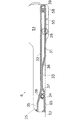
紙幣取扱装置に適用した本発明の紙葉類取扱装置の実施の形態を図1〜図22について以下説明する。本明細書では、「前」又は「前部」は、図13のX軸方向に沿う鑑別装置(2)の紙幣挿入口(53)側(図面上左側)を示し、「奥」又は「後部」は、X軸方向に沿う反対側(図面上右側)を示す。また、「上」及び「上部」は、Y軸方向に沿う上方側を示し、「下」及び「下部」は、Y軸方向に沿う下方側を示す。 An embodiment of the paper sheet handling apparatus of the present invention applied to a banknote handling apparatus will be described below with reference to FIGS. In this specification, “front” or “front” indicates the bill insertion slot (53) side (left side in the drawing) of the discrimination device (2) along the X-axis direction in FIG. "Indicates the opposite side (right side in the drawing) along the X-axis direction. Further, “upper” and “upper” indicate the upper side along the Y-axis direction, and “lower” and “lower” indicate the lower side along the Y-axis direction.
図1に示すように、本発明の紙幣取扱装置は、フレーム(1)と、フレーム(1)に着脱可能に取り付けられる鑑別装置(2)と、フレーム(1)と鑑別装置(2)との間に設けられて鑑別装置(2)をフレーム(1)に着脱可能に取り付ける連結装置(4)と、フレーム(1)に着脱可能に取り付けられて鑑別装置(2)から搬送される紙幣を収納する収納装置(3)とを備える。フレーム(1)は、一対の側壁(41)と、一対の側壁(41)の後部間を接続する後壁(42)と、一対の側壁(41)の前部間を接続するブラケット(7)とを備える。また、鑑別装置(2)の前下部には、鑑別装置(2)をブラケット(7)に固定するラッチ装置(8)が設けられる。ABS樹脂、ポリカーボネート樹脂、アクリル樹脂、ポリアミド樹脂、ポリアセタール樹脂又はこれらの何れかの混合樹脂の射出成形又はアルミニウム若しくは鉄等の金属板のプレス成型によりフレーム(1)、鑑別装置(2)及び収納装置(3)の外殻を形成できる。 As shown in FIG. 1, the bill handling apparatus of the present invention includes a frame (1), a discrimination device (2) that is detachably attached to the frame (1), a frame (1), and a discrimination device (2). A connecting device (4) that is provided between the frame (1) and attaches the identification device (2) to the frame (1) in a detachable manner, and stores bills that are detachably attached to the frame (1) and conveyed from the identification device (2) And a storage device (3). The frame (1) includes a pair of side walls (41), a rear wall (42) connecting the rear portions of the pair of side walls (41), and a bracket (7) connecting the front portions of the pair of side walls (41). With. A latch device (8) for fixing the discrimination device (2) to the bracket (7) is provided at the front lower part of the discrimination device (2). Frame (1), discrimination device (2), and storage device by injection molding of ABS resin, polycarbonate resin, acrylic resin, polyamide resin, polyacetal resin or mixed resin of any of these or press molding of metal plate such as aluminum or iron The outer shell of (3) can be formed.
図2及び図3に示す実施の形態では、連結装置(4)は、フレーム(1)の一対の側壁(41)の各々に形成されるカム案内部(5)と、鑑別装置(2)の一対の側壁(51)の各々に形成されかつカム案内部(5)に接触する従動部(6)とを備える。連結装置(4)のカム案内部(5)は、垂直に配置されるフレーム(1)の一対の側壁(41)に形成され、連結装置(4)の従動部(6)は、垂直に配置される鑑別装置(2)の一対の側壁(51)に形成され、ブラケット(7)は、フレーム(1)の一対の側壁(41)に対して直角に配置される。連結装置(4)は、成型される樹脂若しくは金属又は成型される樹脂と金属との組み合わせ材料により形成される。カム案内部(5)は、フレーム(1)の一対の側壁(41)の各々に形成され、従動部(6)は、鑑別装置(2)の一対の側壁(51)の各々に形成される。カム案内部(5)は、フレーム(1)の側壁(41)に水平に形成される遠位通路(10)と、遠位通路(10)に続き傾斜する接近通路(11)と、接近通路(11)に続く係止通路(12)とを備える。遠位通路(10)は、遠位面(13)と、遠位面(13)に対向して突出する突起面(14)と、突起面(14)の前部に形成される入口傾斜面(19)とにより形成される。遠位通路(10)と係止通路(12)との間に設けられる接近通路(11)は、遠位面(13)から連続して傾斜する第1の傾斜面(15)と、第1の傾斜面(15)に平行に突起面(14)から連続して傾斜する第2の傾斜面(16)とにより形成される。係止通路(12)は、遠位面(13)に平行にかつ第2の傾斜面(16)に連続して延伸する近位面(20)と、遠位面(13)に平行にかつ第1の傾斜面(15)に連続して延伸する係止面(21)と、近位面(20)と係止面(21)との間に形成される当接面(22)とにより形成される。フレーム(1)に固定されるブラケット(7)は、入口傾斜面(19)の前方に配置され、遠位面(13)とブラケット(7)は、遠位通路(10)の入口(23)を構成する。 In the embodiment shown in FIGS. 2 and 3, the connecting device (4) includes a cam guide portion (5) formed on each of the pair of side walls (41) of the frame (1), and a discrimination device (2). And a driven portion (6) formed on each of the pair of side walls (51) and in contact with the cam guide portion (5). The cam guide portion (5) of the coupling device (4) is formed on the pair of side walls (41) of the vertically arranged frame (1), and the driven portion (6) of the coupling device (4) is arranged vertically. The bracket (7) is formed at right angles to the pair of side walls (41) of the frame (1). The coupling device (4) is formed of a resin or metal to be molded or a combination material of a resin to be molded and a metal. The cam guide portion (5) is formed on each of the pair of side walls (41) of the frame (1), and the driven portion (6) is formed on each of the pair of side walls (51) of the discrimination device (2). . The cam guide (5) includes a distal passage (10) formed horizontally in the side wall (41) of the frame (1), an approach passage (11) inclined following the distal passage (10), and an access passage. A locking passage (12) following (11). The distal passage (10) includes a distal surface (13), a projecting surface (14) projecting opposite the distal surface (13), and an inlet inclined surface formed at the front of the projecting surface (14). (19). The access passage (11) provided between the distal passage (10) and the locking passage (12) includes a first inclined surface (15) continuously inclined from the distal surface (13), and a first And a second inclined surface (16) inclined continuously from the projection surface (14) in parallel to the inclined surface (15). The locking passageway (12) has a proximal surface (20) extending parallel to the distal surface (13) and continuously to the second inclined surface (16), parallel to the distal surface (13) and A locking surface (21) extending continuously from the first inclined surface (15) and a contact surface (22) formed between the proximal surface (20) and the locking surface (21) It is formed. The bracket (7) fixed to the frame (1) is arranged in front of the inlet inclined surface (19), and the distal surface (13) and the bracket (7) are connected to the inlet (23) of the distal passage (10). Configure.
従動部(6)は、第1の従動面(31)と、第1の従動面(31)に対し平行で一定間隔離間する第2の従動面(32)と、第2の傾斜面(16)に対し平行で第1の従動面(31)に連続する第3の傾斜面(36)と、第1の従動面(31)に対し平行で第3の傾斜面(36)に連続する第3の従動面(33)と、第3の従動面(33)に連続する第4の傾斜面(37)と、第3の従動面(33)に対して平行で第4の傾斜面(37)に連続する第4の従動面(34)と、第3の傾斜面(36)に平行に第2の従動面(32)に連続する第5の傾斜面(38)と、第2の従動面(32)に平行でかつ第5の傾斜面(38)に連続する第5の従動面(35)と、第5の従動面(35)の端部に設けられて遠位通路(10)の入口(23)の縁部(24)に当接又は対向する突起(25)と、第1の従動面(31)と第2の従動面(32)とを接続する湾曲する端面(39)とを備える。端面(39)は、係止通路(12)の当接面(22)と相補的形状を有する。 The driven portion (6) includes a first driven surface (31), a second driven surface (32) parallel to the first driven surface (31) and spaced apart by a predetermined distance, and a second inclined surface (16 ) Parallel to the first driven surface (31) and the third inclined surface (36) parallel to the first driven surface (31) and continuous to the third inclined surface (36). 3 driven surface (33), a fourth inclined surface (37) continuous to the third driven surface (33), and a fourth inclined surface (37) parallel to the third driven surface (33). ), A fourth driven surface (34) continuous to the second inclined surface (36), a fifth inclined surface (38) continuous to the second driven surface (32) in parallel with the third inclined surface (36), and a second driven A fifth driven surface (35) parallel to the surface (32) and continuing to the fifth inclined surface (38), and a distal passage (10) provided at the end of the fifth driven surface (35) A curved end face (39) connecting the projection (25) abutting against or facing the edge (24) of the inlet (23) and the first driven surface (31) and the second driven surface (32) With. The end surface (39) has a shape complementary to the contact surface (22) of the locking passageway (12).
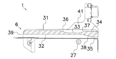
図2及び図4に示すように、鑑別装置(2)の搬送装置を構成する駆動歯車(26)が鑑別装置(2)に設けられ、図3及び図5に示すように、押込装置(105)の従動歯車(27)が収納装置(3)内に設けられる。例えば、当接面(22)に接触する係止通路(12)の最奥部に従動部(6)が配置されて、鑑別装置(2)と収納装置(3)とをフレーム(1)に正しく取り付けた図13に示す装着位置では、従動歯車(27)は、駆動歯車(26)に適切かつ直接的に駆動連結される。図4に示すように、鑑別装置(2)内の図示しない紙幣の搬送通路の出口となる搬送通路出口(55)と、搬送装置(102)の駆動歯車(26)を外部に露出させる開口部(57)とが鑑別装置(2)の底面(52)に設けられる。鑑別装置(2)は、紙幣を搬送する搬送装置(102)により回転する少なくとも1対の駆動歯車(26)を有する。駆動歯車(26)は、収納装置(3)内に設けられて収納装置(3)内で紙幣を搬送する図示しない収納搬送装置を駆動すると共に、収納装置(3)内の押込装置(105)を駆動する。例えば、駆動歯車(26)は、正転時に収納搬送装置を駆動し、逆転時に押込装置(105)を駆動する。この場合に、駆動歯車(26)の逆転時に収納搬送装置の逆転を防止する一方向回転クラッチを設けることができる。1対の駆動歯車(26)の各々少なくとも一部は、歯車開口部(57)の開口面を越えて露出して、収納装置(3)の従動歯車(27)に駆動連結される。 As shown in FIGS. 2 and 4, a drive gear (26) that constitutes the conveying device of the discrimination device (2) is provided in the discrimination device (2). As shown in FIGS. ) Driven gear (27) is provided in the storage device (3). For example, the innermost follower (6) of the locking passageway (12) that contacts the abutting surface (22) is disposed, and the discrimination device (2) and the storage device (3) are attached to the frame (1). In the correctly mounted position shown in FIG. 13, the driven gear (27) is appropriately and directly connected to the drive gear (26). As shown in FIG. 4, a conveyance passage outlet (55) serving as an outlet of a bill conveyance passage (not shown) in the identification device (2) and an opening for exposing the drive gear (26) of the conveyance device (102) to the outside. (57) is provided on the bottom surface (52) of the discrimination device (2). The identification device (2) has at least one pair of drive gears (26) rotated by a transport device (102) for transporting banknotes. The drive gear (26) is provided in the storage device (3) and drives a storage transport device (not shown) that transports banknotes in the storage device (3), and also pushes in the storage device (3). Drive. For example, the drive gear (26) drives the storage / conveyance device during normal rotation and drives the pushing device (105) during reverse rotation. In this case, it is possible to provide a one-way rotation clutch that prevents the storage and conveyance device from rotating in reverse when the drive gear (26) rotates in reverse. At least a part of each of the pair of drive gears (26) is exposed beyond the opening surface of the gear opening (57) and is drivingly connected to the driven gear (27) of the storage device (3).
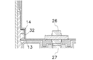
また、鑑別装置(2)の底面(52)から収納装置方向に突出する複数の防御突起(58)が駆動歯車(26)の周辺に設けられる。防御突起(58)の突出量は、駆動歯車(26)の突出量と同一か又はそれ以上に設定され、駆動歯車(26)の周辺を包囲する。防御突起(58)は、紙幣の搬送通路出口(55)に対して直角にかつ互いに平行に延伸する。図5に示すように、鑑別装置(2)の底面(52)に平行に設けられる収納装置(3)の上面(62)には、搬送される紙幣を受け入れる紙幣取入口(63)と、上面(62)上で紙幣取入口(63)に対して直角方向に帯状に伸びる複数の係合溝(64)とが設けられる。収納装置(3)の上面(62)から内側に窪む係合溝(64)は、収納装置(3)の上面(62)に長さ方向に延伸する。押込装置(105)の従動歯車(27)を外部に露出させる開口部(67)が係合溝(64)に設けられ、係合溝(64)の内側に細長い複数の突起(65)が設けられる。フレーム(1)に鑑別装置(2)を装着する際に、鑑別装置(2)の防御突起(58)は、係合溝(64)に係合されると共に、鑑別装置(2)の駆動歯車(26)と防御突起(58)との間に複数の突起(65)が嵌合され、鑑別装置(2)の搬送通路出口(55)と収納装置(3)の紙幣取入口(63)とを整合させる。 A plurality of protective projections (58) projecting from the bottom surface (52) of the discrimination device (2) toward the storage device are provided around the drive gear (26). The amount of protrusion of the protective protrusion (58) is set to be equal to or greater than the amount of protrusion of the drive gear (26), and surrounds the periphery of the drive gear (26). The protective protrusions (58) extend perpendicular to the bill conveyance path outlet (55) and parallel to each other. As shown in FIG. 5, on the upper surface (62) of the storage device (3) provided in parallel with the bottom surface (52) of the discrimination device (2), there are a bill intake port (63) for receiving the conveyed bills, and an upper surface. (62) A plurality of engaging grooves (64) extending in a band shape in a direction perpendicular to the banknote inlet (63) are provided. The engagement groove (64) recessed inward from the upper surface (62) of the storage device (3) extends in the length direction to the upper surface (62) of the storage device (3). An opening (67) that exposes the driven gear (27) of the pushing device (105) to the outside is provided in the engagement groove (64), and a plurality of elongated protrusions (65) are provided inside the engagement groove (64). It is done. When the identification device (2) is attached to the frame (1), the defense protrusion (58) of the identification device (2) is engaged with the engagement groove (64) and the drive gear of the identification device (2). A plurality of protrusions (65) are fitted between (26) and the protective protrusion (58), and the conveyance passage outlet (55) of the discrimination device (2) and the banknote intake (63) of the storage device (3) Align.
図6〜図9に示すように、鑑別装置(2)のラッチ装置(8)は、軸(84)に回転可能に取り付けられる係止レバー(81)と、回転可能に軸(88)に固定される作動レバー(82)と、軸(88)に固定されるハンドル(83)とを備える。係止レバー(81)は、ブラケット(7)に形成される開口部(7a)に係止するストッパ(85)と、引張弾性力を発生するスプリング(86)の一端が接続される付勢端部(89)と、作動レバー(82)に回転可能に連結されるピン(87)が嵌合される長孔(90)とを有する。鑑別装置(2)の側壁(51)に固定されるスプリング(86)は、係止レバー(81)を軸(84)の周りに反時計方向に付勢する。鑑別装置(2)をフレーム(1)に装着する際に、ストッパ(85)がブラケット(7)の上面を摺動するとき、スプリング(86)の弾力に抗して係止レバー(81)を時計方向に回転させるレバー傾斜面(85a)を有する。また、ハンドル(83)が引張操作されたときも同様に係止レバー(81)を時計方向に回転させる。 As shown in FIGS. 6 to 9, the latch device (8) of the discrimination device (2) is fixed to the shaft (88) and the locking lever (81) rotatably attached to the shaft (84). And a handle (83) fixed to the shaft (88). The locking lever (81) is a biasing end to which a stopper (85) that locks into the opening (7a) formed in the bracket (7) and one end of a spring (86) that generates a tensile elastic force are connected. And a slot (90) into which a pin (87) rotatably connected to the operating lever (82) is fitted. The spring (86) fixed to the side wall (51) of the discrimination device (2) urges the locking lever (81) counterclockwise around the shaft (84). When attaching the identification device (2) to the frame (1), when the stopper (85) slides on the top surface of the bracket (7), the locking lever (81) is pushed against the elasticity of the spring (86). A lever inclined surface (85a) that rotates clockwise is provided. Similarly, when the handle (83) is pulled, the locking lever (81) is rotated clockwise.
図10及び図11に示すように、鑑別装置(2)をフレーム(1)に装着するとき、従動部(6)の端面(39)を遠位通路(10)の入口(23)内に挿入すると、端面(39)が入口傾斜面(19)に当接し、入口傾斜面(19)に沿って突起面(14)上に案内される。従動部(6)の第1の従動面(31)は、突起面(14)に当接して摺動され、従動部(6)の第2の従動面(32)は、遠位通路(10)の遠位面(13)に対向し又は接触して遠位通路(10)に沿って摺動される。このとき、従動部(6)は、ブラケット(7)に対する突起面(14)の高さ分だけ収納装置(3)から離間してカム案内部(5)に沿ってフレーム(1)の奥に移動される。従動部(6)の第1の従動面(31)がカム案内部(5)の突起面(14)上に当接する状態では、鑑別装置(2)の底面(52)及び底面(52)から突出する一対の駆動歯車(26)及び複数の防御突起(58)は、収納装置(3)の上面(62)には接触しない。 As shown in FIGS. 10 and 11, when the discrimination device (2) is attached to the frame (1), the end surface (39) of the follower (6) is inserted into the inlet (23) of the distal passage (10). Then, the end surface (39) comes into contact with the entrance inclined surface (19) and is guided along the entrance inclined surface (19) onto the projecting surface (14). The first driven surface (31) of the driven portion (6) is slid in contact with the projecting surface (14), and the second driven surface (32) of the driven portion (6) is moved to the distal passage (10 ) And slid along the distal passage (10) opposite or in contact with the distal surface (13). At this time, the driven portion (6) is separated from the storage device (3) by the height of the projecting surface (14) with respect to the bracket (7) and is located behind the frame (1) along the cam guide portion (5). Moved. In a state where the first driven surface (31) of the driven portion (6) is in contact with the projecting surface (14) of the cam guide portion (5), the bottom surface (52) and the bottom surface (52) of the discrimination device (2) The pair of protruding drive gears (26) and the plurality of defense protrusions (58) do not contact the upper surface (62) of the storage device (3).
図10に示す状態から更に鑑別装置(2)をフレーム(1)の奥に押込むと、図12に示すように、従動部(6)の端面(39)が第1の傾斜面(15)に接触し、従動部(6)の第3の傾斜面(36)が第2の傾斜面(16)に接触して摺動し、従動部(6)及び鑑別装置(2)全体は、図12の矢印方向で示すように、第1及び第2の傾斜面(15,16)により形成される接近通路(11)に沿って収納装置(3)に向って斜めに移動する。従動部(6)が係止通路(12)に到達して、従動部(6)の第1の従動面(31)が近位面(20)に接触すると、同時に、鑑別装置(2)の底面(52)から突出する1対の駆動歯車(26)及び複数の防御突起(58)は、収納装置(3)の上面(62)の複数の係合溝(64)内に嵌合される。
When the discrimination device (2) is further pushed into the back of the frame (1) from the state shown in FIG. 10, as shown in FIG. 12, the end surface (39) of the driven portion (6) is the first inclined surface (15). The third inclined surface (36) of the driven part (6) contacts and slides on the second inclined surface (16), and the driven part (6) and the discrimination device (2) as a whole are shown in FIG. As shown by the direction of the
鑑別装置(2)をフレーム(1)に向って奥に押込むと、図13に示すように、従動部(6)は、カム案内部(5)の係止通路(12)に沿って僅かに水平に移動し、従動部(6)の端面(39)は、係止通路(12)の当接面(22)に接触して、鑑別装置(2)は、正しく装着位置に配置され、従動部(6)の進行方向への更なる移動が阻止される。鑑別装置(2)が正しく装着位置に配置されると、駆動歯車(26)は、従動歯車(27)に駆動連結される。また、従動部(6)の第4の傾斜面(37)は、入口傾斜面(19)に接触又は対向し、従動部(6)の突起(25)は、入口(23)の縁部(24)に対向し又は接触する。同時に、図13に示すように、従動部(6)の第3の傾斜面(36)とカム案内部(5)の第2の傾斜面(16)との間に間隙が形成される。別法として、従動部(6)が係止通路(12)に到達して、従動部(6)の第1の従動面(31)が近位面(20)に接触する時点で、駆動歯車(26)と従動歯車(27)とを駆動連結してもよく、更に、駆動歯車(26)と従動歯車(27)との少なくとも一方をバネ等の弾性体により付勢して、弾性的に緩衝連結させても良い。 When the discrimination device (2) is pushed inward toward the frame (1), the driven portion (6) slightly moves along the locking passage (12) of the cam guide portion (5) as shown in FIG. The end surface (39) of the driven portion (6) contacts the contact surface (22) of the locking passage (12), and the discrimination device (2) is correctly placed at the mounting position. Further movement of the follower (6) in the traveling direction is prevented. When the discrimination device (2) is correctly placed at the mounting position, the drive gear (26) is drivingly connected to the driven gear (27). The fourth inclined surface (37) of the driven portion (6) is in contact with or faces the inlet inclined surface (19), and the protrusion (25) of the driven portion (6) is the edge portion of the inlet (23) ( Oppose or touch 24). At the same time, as shown in FIG. 13, a gap is formed between the third inclined surface (36) of the driven portion (6) and the second inclined surface (16) of the cam guide portion (5). Alternatively, when the driven portion (6) reaches the locking passageway (12) and the first driven surface (31) of the driven portion (6) contacts the proximal surface (20), the drive gear (26) and the driven gear (27) may be drivingly connected, and at least one of the driving gear (26) and the driven gear (27) is urged by an elastic body such as a spring to elastically A buffer connection may be used.
このように、鑑別装置(2)をフレーム(1)に装着するとき、遠位通路(10)に沿って従動部(6)を移動することにより、ブラケット(7)及び収納装置(3)から離間する位置に搬送装置(102)を保持しながら、鑑別装置(2)の駆動歯車をブラケット(7)又は収納装置(3)に接触させずに、収納装置(3)の上面(62)に対して鑑別装置(2)を相対的に平行に水平に移動し、その後、収納装置(3)に接近させながら、接近通路(11)に沿って従動部(6)を斜めに移動して、係止通路(12)に達する。このとき、従動部(6)の第1の従動面(31)は、カム案内部(5)の近位面(20)に当接する。従動部(6)が係止通路(12)に達したとき又は係止通路(12)に沿って従動部(6)を僅かに奥に移動して、係止通路(12)の装着位置に従動部(6)が到達したとき、鑑別装置(2)の駆動歯車(26)を収納装置(3)の従動歯車(27)に直接駆動連結させて、駆動歯車(26)の損傷を防止することができる。また、従動部(6)が係止通路(12)に達したとき、鑑別装置(2)の底面(52)の防御突起(58)を収納装置(3)の上面(62)の係合溝(64)内に嵌合させると共に、鑑別装置(2)の搬送通路出口(55)と収納装置(3)の紙幣取入口(63)とを整合させて、鑑別装置(2)を正しく装着位置に配置することができる。 Thus, when mounting the discrimination device (2) to the frame (1), by moving the follower (6) along the distal passage (10), the bracket (7) and the storage device (3) While holding the transport device (102) in a separated position, the drive gear of the discrimination device (2) is not brought into contact with the bracket (7) or the storage device (3), and is placed on the upper surface (62) of the storage device (3). On the other hand, the identification device (2) is moved relatively parallel and horizontally, and then the driven portion (6) is moved obliquely along the approach passage (11) while approaching the storage device (3), Reach the locking passage (12). At this time, the first driven surface (31) of the driven portion (6) abuts on the proximal surface (20) of the cam guide portion (5). When the driven portion (6) reaches the locking passageway (12), or moves the driven portion (6) slightly along the locking passageway (12) to the mounting position of the locking passageway (12). When the driven portion (6) arrives, the drive gear (26) of the discrimination device (2) is directly connected to the driven gear (27) of the storage device (3) to prevent damage to the drive gear (26). be able to. When the driven portion (6) reaches the locking passageway (12), the protective protrusion (58) on the bottom surface (52) of the discrimination device (2) is connected to the engagement groove on the top surface (62) of the storage device (3). (64) is fitted in, and the transfer passage outlet (55) of the identification device (2) is aligned with the banknote inlet (63) of the storage device (3), so that the identification device (2) is correctly installed. Can be arranged.
本実施の形態では、カム案内部(5)と従動部(6)との間に付加的構成部品を設けずに、フレーム(1)と鑑別装置(2)との外側形状により連結装置(4)を形成できる。また、鑑別装置(2)と収納装置(3)との間に従来必要とされた連結装置を設ける必要がないため、紙幣を収容する収納装置(3)の高さ方向又は長手方向の容量を拡張できる。収納装置(3)を長さ方向に拡張すると、従来では収納できない長さの紙幣も収納でき、紙幣取扱装置の活用幅を広げる事ができる。鑑別装置(2)の駆動歯車(26)は、外部物体との衝突に対して防御突起(58)により保護され、収納装置(3)の従動歯車(27)が収納装置(3)の上面よりも突出しないため、鑑別装置(2)の着脱操作による歯車(26,27)の損傷を防止でき、紙幣取扱装置の使用寿命を延長することができる。 In this embodiment, an additional component is not provided between the cam guide portion (5) and the driven portion (6), and the connecting device (4) is formed by the outer shape of the frame (1) and the discrimination device (2). ) Can be formed. Further, since it is not necessary to provide a connecting device that has been conventionally required between the discrimination device (2) and the storage device (3), the capacity in the height direction or the longitudinal direction of the storage device (3) for storing banknotes is increased. Can be expanded. When the storage device (3) is extended in the length direction, it is possible to store banknotes of a length that cannot be stored conventionally, and the utilization range of the banknote handling device can be expanded. The drive gear (26) of the discrimination device (2) is protected by a protective projection (58) against collision with an external object, and the driven gear (27) of the storage device (3) is moved from the upper surface of the storage device (3). Therefore, the gears (26, 27) can be prevented from being damaged by the attaching / detaching operation of the discrimination device (2), and the service life of the bill handling device can be extended.
図12及び図13に示すように、ストッパ(81)がブラケット(7)の表面に当接しながら従動部(6)が遠位通路(10)を通過するとき又は第1の傾斜面(15)及び第2の傾斜面(16)に沿って従動部(6)が接近通路(11)を通過して、従動部(6)がカム案内部(5)に沿って下降するとき、ストッパ(81)は、ブラケット(7)の表面に当接する。この場合に、ラッチ装置(8)のストッパ(85)のレバー傾斜面(85a)がブラケット(7)の縁部(7b)に当接するため、係止レバー(81)は、スプリング(86)の弾力に抗して軸(84)の周りに時計方向に回転され、ブラケット(7)の表面上を摺動する。従動部(6)の端面(39)が係止通路(12)の当接面(22)に接触すると、スプリング(86)の弾力により係止レバー(81)が反時計方向に回転されて、ストッパ(85)は、ブラケット(7)に形成される開口部(7a)に係止されるため、ラッチ装置(8)は、フレーム(1)の所定の位置に鑑別装置(2)を位置決めすると共に、フレーム(1)からの鑑別装置(2)の引抜を阻止する。 As shown in FIGS. 12 and 13, when the follower (6) passes through the distal passage (10) while the stopper (81) abuts the surface of the bracket (7), or the first inclined surface (15). When the driven portion (6) passes through the approach passage (11) along the second inclined surface (16) and the driven portion (6) descends along the cam guide portion (5), the stopper (81 ) Contacts the surface of the bracket (7). In this case, since the lever inclined surface (85a) of the stopper (85) of the latch device (8) contacts the edge (7b) of the bracket (7), the locking lever (81) is connected to the spring (86). It is rotated clockwise around the shaft (84) against elasticity and slides on the surface of the bracket (7). When the end surface (39) of the driven portion (6) contacts the contact surface (22) of the locking passage (12), the locking lever (81) is rotated counterclockwise by the elasticity of the spring (86), Since the stopper (85) is locked in the opening (7a) formed in the bracket (7), the latch device (8) positions the discrimination device (2) at a predetermined position of the frame (1). At the same time, the withdrawal of the discrimination device (2) from the frame (1) is prevented.
鑑別装置(2)をフレーム(1)から引出すには、スプリング(86)の弾力に抗してハンドル(83)を手動で下方に回転すると、ハンドル(83)が軸(88)の周りに反時計方向に回転されるので、ピン(87)を介して係止レバー(81)が時計方向に上方に回転される。従って、係止レバー(81)が時計方向に回転されて、ストッパ(85)と開口部(7a)との係合が解除されるため、鑑別装置(2)を手前に引いて、従動部(6)をカム案内部(5)から分離し、鑑別装置(2)をフレーム(1)から取り外すことができる。 To pull out the identification device (2) from the frame (1), the handle (83) is rotated around the shaft (88) by manually rotating the handle (83) against the elasticity of the spring (86). Since it is rotated in the clockwise direction, the locking lever (81) is rotated upward in the clockwise direction via the pin (87). Therefore, the locking lever (81) is rotated clockwise, and the engagement between the stopper (85) and the opening (7a) is released.Therefore, the discrimination device (2) is pulled forward and the driven portion ( 6) can be separated from the cam guide (5), and the discrimination device (2) can be removed from the frame (1).
図1〜図15に示す実施の形態では、フレーム(1)にカム案内部(5)を形成し、鑑別装置(2)の一対の側壁(51)に従動部(6)を形成する例を示したが、図16〜図20に示す第2の実施の形態のように、フレーム(1)に従動部(6)を形成し、鑑別装置(2)の一対の側壁(51)にカム案内部(5)を形成することもできる。第2の実施の形態に示す構造及び作用効果は、前記の説明から理解できよう。第2の実施の形態では、図1〜図15に示す第1の実施の形態を示す部分と同一の部分には同一の符号を付する。 In the embodiment shown in FIGS. 1 to 15, an example in which the cam guide portion (5) is formed on the frame (1) and the driven portion (6) is formed on the pair of side walls (51) of the discrimination device (2). As shown in the second embodiment shown in FIGS. 16 to 20, the follower (6) is formed on the frame (1), and the cam guide is provided on the pair of side walls (51) of the discrimination device (2). The part (5) can also be formed. The structure and operational effects shown in the second embodiment can be understood from the above description. In the second embodiment, the same parts as those shown in the first embodiment shown in FIGS.
本発明による紙幣取扱装置の第3の実施の形態を図21と図22に示す。図21及び図22では、図1〜図20に示す部分と実質的に同一の箇所には、同一の符号を付して説明を省略する。第3の実施の形態では、第1及び第2の実施の形態で示すカム案内部(5)の遠位面(13)と第1の傾斜面(15)とを除去し、ほぼ台形又は平行四辺形断面に従動部(6)の断面形状を単純化し、遠位面(13)と第1の傾斜面(15)とを省略する点で、第1及び第2の実施形態よりも簡便な構造を有する。第3の実施の形態の構成及び作用効果は、第1及び第2の実施の形態と同様である。第3の実施の形態では、カム案内部(5)をフレーム(1)に形成し、従動部(6)を鑑別装置(2)に形成する例を図示するが、逆に、図16〜図18に示すように、従動部(6)をフレーム(1)に形成し、カム案内部(5)を鑑別装置(2)に形成してもよい。 A third embodiment of the banknote handling apparatus according to the present invention is shown in FIGS. In FIG.21 and FIG.22, the same code | symbol is attached | subjected to the location substantially the same as the part shown in FIGS. 1-20, and description is abbreviate | omitted. In the third embodiment, the distal surface (13) and the first inclined surface (15) of the cam guide portion (5) shown in the first and second embodiments are removed, and substantially trapezoidal or parallel. It is simpler than the first and second embodiments in that the cross-sectional shape of the follower portion (6) is simplified and the distal surface (13) and the first inclined surface (15) are omitted. It has a structure. The configuration and operational effects of the third embodiment are the same as those of the first and second embodiments. In the third embodiment, an example in which the cam guide portion (5) is formed in the frame (1) and the driven portion (6) is formed in the discrimination device (2) is illustrated. As shown in FIG. 18, the driven portion (6) may be formed on the frame (1), and the cam guide portion (5) may be formed on the discrimination device (2).
本発明の前記実施の形態では、種々の変更が可能である。例えば、フレーム(1)の剛性を向上するブラケット(7)をフレーム(1)の一対の側壁(41)間に接続される例を説明したが、フレーム(1)の一対の側壁(41)間に別体若しくは一体で固定し又はフレーム(1)に固定される収納装置(3)の天板によりブラケットを兼用してもよい。また、図示の構造を転倒させて収納装置の下方に鑑別装置を配置してフレームに取り付ける転倒型構造の紙幣取扱装置にも本発明を適用することができる。 Various modifications can be made in the embodiment of the present invention. For example, the bracket (7) for improving the rigidity of the frame (1) has been described as being connected between the pair of side walls (41) of the frame (1). The bracket may also be used as a top plate of the storage device (3) fixed separately or integrally to the frame (1). Further, the present invention can be applied to a banknote handling apparatus having an overturning structure in which the illustrated structure is turned over and a discrimination device is disposed below the storage device and attached to the frame.
本発明の実施の形態による作用効果を列挙すれば、次の通りである。
[1] フレーム(1)に対し鑑別装置(2)を着脱自在に装着することができる。
[2] 鑑別装置(2)の駆動歯車(26)等の搬送装置(102)を機械的に損傷せずに、搬送装置(102)を収納装置(3)に係脱自在に駆動連結することができる。
[3] フレーム(1)の側壁(41)の形状と鑑別装置(2)の側壁(51)の形状により形成される連結装置(4)のカム案内部(5)と従動部(6)とを分離可能に連動させることができる。
[4] カム案内部(5)と従動部(6)との間に付加的構成部品を設ける必要がない。
[5] 鑑別装置(2)と収納装置(3)との間に連結装置を設ける必要がなく、その分、紙幣を収容する収納装置(3)の容量を増加することができる。
[6] より大きいサイズの紙幣を収納装置(3)に収容することができる。
[7] 防御突起(58)により鑑別装置(2)の底面(52)から露出する駆動歯車(26)を保護することができる。
The effects according to the embodiment of the present invention are listed as follows.
[1] The discrimination device (2) can be detachably attached to the frame (1).
[2] The transporting device (102) is detachably drive-coupled to the storage device (3) without mechanically damaging the transporting device (102) such as the drive gear (26) of the discrimination device (2). Can do.
[3] The cam guide portion (5) and the follower portion (6) of the connecting device (4) formed by the shape of the side wall (41) of the frame (1) and the shape of the side wall (51) of the discrimination device (2) Can be linked in a separable manner.
[4] There is no need to provide an additional component between the cam guide part (5) and the driven part (6).
[5] There is no need to provide a connecting device between the discrimination device (2) and the storage device (3), and the capacity of the storage device (3) for storing banknotes can be increased accordingly.
[6] Larger banknotes can be stored in the storage device (3).
[7] The drive gear (26) exposed from the bottom surface (52) of the discrimination device (2) can be protected by the protective protrusion (58).
本発明は、有価紙葉を鑑別しかつ収納する紙葉類取扱装置に鑑別装置を着脱自在に取り付ける技術に適用することができる。また、クーポン、銀行券、証券及び代用紙幣等の紙幣以外の有価紙葉にも本発明を適用できることは明らかである。 The present invention can be applied to a technique for detachably attaching a discrimination device to a paper sheet handling device that discriminates and stores valuable paper sheets. It is also clear that the present invention can be applied to valuable paper sheets other than banknotes such as coupons, banknotes, securities, and substitute banknotes.
(1)・・フレーム、 (2)・・鑑別装置、 (3)・・収納装置、 (4)・・連結装置、 (5)・・カム案内部、 (6)・・従動部、 (7)・・ブラケット、 (7a)・・開口部、 (8)・・ラッチ装置、 (10)・・遠位通路、 (11)・・接近通路、 (12)・・係止通路、 (13)・・遠位面、 (14)・・突起面、 (15)・・第1の傾斜面、 (16)・・第2の傾斜面、 (19)・・入口傾斜面、 (20)・・近位面、 (21)・・係止面、 (22)・・当接面、 (23)・・入口、 (24)・・縁部、 (25)・・突起、 (26)・・駆動歯車、 (27)・・従動歯車、 (31)・・第1の従動面、 (32)・・第2の従動面、 (33)・・第3の従動面、 (34)・・第4の従動面、 (35)・・第5の従動面、 (36)・・第3の傾斜面、 (37)・・第4の傾斜面、 (38)・・第5の傾斜面、 (39)・・端面、 (41)・・側壁、 (42)・・後壁、 (51)・・側壁、 (52)・・底面、 (53)・・紙幣挿入口、 (55)・・搬送通路出口、 (57)・・歯車開口部、 (58)・・防御突起、 (62)・・上面、 (63)・・紙幣取入口、 (64)・・係合溝、 (65)・・突起、 (70)・・接近平面、 (71)・・平坦突起、 (77)・・凹部、 (81)・・係止レバー、 (82)・・作動レバー、 (83)・・ハンドル、 (84)・・軸、 (85)・・ストッパ、 (85a)・・レバー傾斜面、 (86)・・スプリング、 (87)・・ピン、 (88)・・軸、 (89)・・付勢端部、 (90)・・長孔、 (100)・・紙幣取扱装置、 (101)・・鑑別装置、 (102)・・搬送装置、 (103)・・収納装置、 (104)・・紙幣収納部、 (105)・・押込装置、 (106)・・ケース、 (108)・・収容空間、 (109)・・搬送通路出口、 (110)・・紙幣取入口、 (111)・・フレーム、 (112)・・従動歯車、 (113)・・駆動歯車、 (115)・・ブラケット、 (116)・・滑動連結構造、 (1) ・ ・ Frame, (2) ・ ・ Difference device, (3) ・ Storage device, (4) ・ Connecting device, (5) ・ Cam guide, (6) ・ Driver, (7・ ・ Bracket, (7a) ・ ・ Opening, (8) ・ Latch device, (10) ・ Distal passage, (11) ・ Access passage, (12) ・ ・ Locking passage, (13) · · Distal surface, (14) · · Projection surface, (15) · · First inclined surface, (16) · · Second inclined surface, (19) · · Inlet inclined surface, (20) · · Proximal surface, (21) ... Locking surface, (22) ... Contact surface, (23) ... Entrance, (24) ... Edge, (25) ... Projection, (26) ... Drive Gear, (27) ... driven gear, (31) ... first driven surface, (32) ... second driven surface, (33) ... third driven surface, (34) ... fourth (35) ・ ・ 5th driven surface, (36) ・ ・ 3rd inclined surface, (37) ・ ・ 4th inclined surface, (38) ・ ・ 5th inclined surface, (39 ) ... End face, (41) ... Side wall, (42) ... Back wall, (51) ... Side wall, (52) ・ ・ Bottom surface, (53) ・ ・ Bill insertion slot, (55) ・ ・ Carrying passage exit, (57) ・ ・ Gear opening, (58) ・ ・ Protective protrusion, (62) ・ ・ Top surface, ( 63) ・ ・ Bill intake, (64) ・ ・ Engagement groove, (65) ・ ・ Protrusion, (70) ・ ・ Flat surface, (71) ・ ・ Flat projection, (77) ・ ・ Recess, (81)・ ・ Locking lever, (82) ・ ・ Operating lever, (83) ・ ・ Handle, (84) ・ ・ Shaft, (85) ・ ・ Stopper, (85a) ・ ・ Lever inclined surface, (86) ・ ・ Spring (87) ・ ・ Pin, (88) ・ ・ Shaft, (89) ・ ・ Biasing end, (90) ・ ・ Long hole, (100) ・ ・ Bill handling device, (101) ・ ・ Difference device, (102) ・ ・ Conveying device, (103) ・ ・ Storage device, (104) ・ ・ Bill storage unit, (105) ・ ・ Pushing device, (106) ・ ・ Case, (108) ・ ・ Storage space, (109 ··········································· 110 (116) ・ ・ Sliding connection structure,
Claims (12)
底面及び底面から下方に突出する駆動歯車を有する搬送装置を備えかつフレームに着脱可能に取り付けられる鑑別装置と、
紙葉収納部、収容空間、収容空間内に配置されて鑑別装置から搬送される紙葉を紙葉収納部内に押し込む押込装置、押込装置を駆動する従動歯車を有しかつフレームに取り付けられる収納装置と、
鑑別装置をフレームに着脱可能に取り付ける連結装置とを備え、
連結装置は、フレームの側壁及び鑑別装置の側壁の一方に形成されるカム案内部と、フレームの側壁及び鑑別装置の側壁の他方に形成されかつカム案内部に係止する従動部とを有し、
カム案内部は、ブラケットから離間してかつ搬送装置の駆動歯車をブラケットに接触させずに、従動部の移動を案内して鑑別装置を水平に移動させる遠位通路と、遠位通路に接続されかつ遠位通路を通過した従動部を収納装置に向って斜めに移動させる接近通路と、接近通路に接続されかつ接近通路を通過した従動部を鑑別装置の装着位置まで水平に移動させて搬送装置の駆動歯車を収納装置の従動歯車に駆動連結させる係止通路とを有することを特徴とする紙葉類取扱装置。 A frame having a pair of side walls and a bracket bridged between the pair of side walls;
A discrimination device including a bottom surface and a transport device having a drive gear projecting downward from the bottom surface and detachably attached to the frame;
A paper storage unit, a storage space, a pressing device that pushes a paper sheet disposed in the storage space and conveyed from the discrimination device into the paper storage unit, a storage device that has a driven gear that drives the pressing device and is attached to the frame When,
A connecting device for detachably attaching the identification device to the frame;
The coupling device has a cam guide portion formed on one of the side wall of the frame and the side wall of the discrimination device, and a driven portion formed on the other of the side wall of the frame and the side wall of the discrimination device and locked to the cam guide portion. ,
The cam guide part is connected to the distal path and the distal path that guides the movement of the driven part and moves the discrimination device horizontally without moving the drive gear of the transport device in contact with the bracket and spaced apart from the bracket. And an approach passage that moves the driven portion that has passed through the distal passage obliquely toward the storage device, and a transport device that horizontally moves the driven portion connected to the access passage and passed through the access passage to the mounting position of the discrimination device. And a latching passage for drivingly connecting the drive gear to the driven gear of the storage device.
連結装置のカム案内部及び従動部の他方を垂直に配置される鑑別装置の一対の側壁に形成し、
水平に配置される鑑別装置の底壁から搬送装置の一部が下方に突出する請求項8に記載の紙葉類取扱装置。 One of the cam guide portion and the driven portion of the coupling device is formed on a pair of side walls of the vertically arranged frame,
The other of the cam guide portion and the driven portion of the coupling device is formed on a pair of side walls of the discrimination device arranged vertically
The paper sheet handling device according to claim 8, wherein a part of the conveying device protrudes downward from a bottom wall of the discrimination device arranged horizontally.
ブラケットは、一対の側壁の前部間を接続し、
カム案内部と従動部との一方をフレームの一対の側壁に形成し、
カム案内部と従動部との他方を鑑別装置の側壁に形成した請求項1に記載の紙葉類取扱装置。 The frame includes a rear wall connecting the rear portions of the pair of side walls,
The bracket connects between the front parts of the pair of side walls,
One of the cam guide portion and the driven portion is formed on the pair of side walls of the frame,
The paper sheet handling device according to claim 1, wherein the other of the cam guide portion and the driven portion is formed on a side wall of the discrimination device.
鑑別装置は、鑑別装置内で紙葉を搬送する搬送装置により駆動される駆動歯車と、鑑別装置の底面から突出する複数の防御突起とを有し、
収納装置は、鑑別装置からの紙葉が通過する紙葉取入口と、紙葉取入口を通過する紙葉を収納する収容空間と、収容空間内の紙葉を紙葉収納部内に押込む押込装置と、押込装置を駆動する従動歯車と、収納装置の上面に形成される複数の係合溝とを有し、
連結装置は、フレームの側壁及び鑑別装置の側壁の一方に形成されるカム案内部と、フレームの側壁及び鑑別装置の側壁の他方に形成されかつカム案内部に係止する従動部とを有し、
鑑別装置の駆動歯車は、複数の防御突起間に配置され、
押込装置の従動歯車は、複数の係合溝間に配置され、
鑑別装置がフレームの取付位置に移動されるとき、搬送装置の駆動歯車が押込装置の従動歯車に駆動連結されると共に、複数の防御突起が収納装置の係合溝内に嵌合され、搬送装置により従動歯車を回転して押込装置を作動することを特徴とする紙葉類取扱装置。 A frame having a pair of side walls and a bracket bridged between the pair of side walls, a discrimination device including a transport device and detachably attached to the frame, a connecting device for detachably attaching the discrimination device to the frame, and an attachment to the frame And a storage device for storing paper sheets conveyed from the discrimination device,
The identification device has a drive gear driven by a conveying device that conveys a paper sheet in the identification device, and a plurality of defense protrusions protruding from the bottom surface of the identification device,
The storage device includes a paper sheet inlet through which the paper sheet from the discrimination device passes, a storage space for storing the paper sheet passing through the paper sheet inlet, and a push for pushing the paper sheet in the storage space into the paper sheet storage unit. An apparatus, a driven gear that drives the pushing device, and a plurality of engagement grooves formed on the upper surface of the storage device,
The coupling device has a cam guide portion formed on one of the side wall of the frame and the side wall of the discrimination device, and a driven portion formed on the other of the side wall of the frame and the side wall of the discrimination device and locked to the cam guide portion. ,
The drive gear of the identification device is arranged between the plurality of defense protrusions,
The driven gear of the pushing device is disposed between the plurality of engaging grooves,
When the discrimination device is moved to the mounting position of the frame, the drive gear of the transport device is drivingly connected to the driven gear of the push-in device, and a plurality of protective projections are fitted into the engagement grooves of the storage device, and the transport device The paper sheet handling device is characterized in that the driven gear is rotated to actuate the pushing device.
Priority Applications (11)
| Application Number | Priority Date | Filing Date | Title |
|---|---|---|---|
| JP2009245957A JP5537117B2 (en) | 2009-10-26 | 2009-10-26 | Paper sheet handling equipment |
| US12/842,156 US8746433B2 (en) | 2009-10-26 | 2010-07-23 | Document handler having validator detachably attached thereto |
| MX2012004909A MX2012004909A (en) | 2009-10-26 | 2010-10-26 | Document handler having validator detachably attached thereto. |
| PCT/JP2010/006325 WO2011052189A1 (en) | 2009-10-26 | 2010-10-26 | Document handler having validator detachably attached thereto |
| EP10826325.2A EP2494529B1 (en) | 2009-10-26 | 2010-10-26 | Document handler having validator detachably attached thereto |
| RU2012121833/08A RU2491643C1 (en) | 2009-10-26 | 2010-10-26 | Document handling device having verification device detachably attached thereto |
| CN201080056289.9A CN102782731B (en) | 2009-10-26 | 2010-10-26 | Document handler having validator detachably attached thereto |
| ES10826325.2T ES2541007T3 (en) | 2009-10-26 | 2010-10-26 | Document management device that has a validator detachably attached to it |
| BR112012009814-4A BR112012009814B1 (en) | 2009-10-26 | 2010-10-26 | DOCUMENT HANDLER THAT HAS A VALIDATOR STUCK OUT OF THIS |
| CA2778755A CA2778755C (en) | 2009-10-26 | 2010-10-26 | Document handler having validator detachably attached thereto |
| TW099136967A TWI446292B (en) | 2009-10-26 | 2010-10-26 | Document handler having validator detachably attached thereto |
Applications Claiming Priority (1)
| Application Number | Priority Date | Filing Date | Title |
|---|---|---|---|
| JP2009245957A JP5537117B2 (en) | 2009-10-26 | 2009-10-26 | Paper sheet handling equipment |
Publications (3)
| Publication Number | Publication Date |
|---|---|
| JP2011090652A JP2011090652A (en) | 2011-05-06 |
| JP2011090652A5 JP2011090652A5 (en) | 2012-11-29 |
| JP5537117B2 true JP5537117B2 (en) | 2014-07-02 |
Family
ID=43897458
Family Applications (1)
| Application Number | Title | Priority Date | Filing Date |
|---|---|---|---|
| JP2009245957A Active JP5537117B2 (en) | 2009-10-26 | 2009-10-26 | Paper sheet handling equipment |
Country Status (11)
| Country | Link |
|---|---|
| US (1) | US8746433B2 (en) |
| EP (1) | EP2494529B1 (en) |
| JP (1) | JP5537117B2 (en) |
| CN (1) | CN102782731B (en) |
| BR (1) | BR112012009814B1 (en) |
| CA (1) | CA2778755C (en) |
| ES (1) | ES2541007T3 (en) |
| MX (1) | MX2012004909A (en) |
| RU (1) | RU2491643C1 (en) |
| TW (1) | TWI446292B (en) |
| WO (1) | WO2011052189A1 (en) |
Families Citing this family (14)
| Publication number | Priority date | Publication date | Assignee | Title |
|---|---|---|---|---|
| JP5484866B2 (en) | 2009-11-16 | 2014-05-07 | 日本金銭機械株式会社 | Paper sheet handling equipment |
| JP5795990B2 (en) * | 2012-05-14 | 2015-10-14 | 日立オムロンターミナルソリューションズ株式会社 | Paper sheet handling equipment and automatic transaction equipment |
| JP2014113935A (en) * | 2012-12-11 | 2014-06-26 | Kojima Press Industry Co Ltd | Air port device for vehicle |
| US9721241B2 (en) * | 2013-09-21 | 2017-08-01 | Jcm American Corporation | Document handler system and method with timed operation |
| US9721414B2 (en) | 2014-10-31 | 2017-08-01 | Crane Payment Innovations, Inc. | Document cassette displacement actuator for document acceptor |
| EP3073453B1 (en) * | 2015-03-27 | 2020-03-25 | Wincor Nixdorf International GmbH | Safe bag module with a handle having one-sided transmission of torque |
| JP6450042B1 (en) * | 2018-03-29 | 2019-01-09 | 日本金銭機械株式会社 | Paper sheet storage unit and paper sheet processing apparatus |
| USD1019785S1 (en) | 2018-08-03 | 2024-03-26 | Aristocrat Technologies, Inc. | Gaming machine |
| CN110102501B (en) * | 2019-04-12 | 2020-11-27 | 远光软件股份有限公司 | Automatic sorting device and method for original certificates |
| JP7433789B2 (en) * | 2019-07-05 | 2024-02-20 | キヤノン株式会社 | Drive transmission device and image forming device equipped with the same |
| CN211237010U (en) * | 2019-07-25 | 2020-08-11 | 日本金钱机械株式会社 | Coin discriminating unit |
| US11195369B2 (en) | 2020-05-05 | 2021-12-07 | Aristocrat Technologies, Inc. | Electronic gaming machine with access door |
| US11941939B2 (en) | 2020-09-24 | 2024-03-26 | Aristocrat Technologies, Inc. | Electronic gaming machine including monitor and podium counterweight |
| US20230045373A1 (en) * | 2021-07-29 | 2023-02-09 | Aristocrat Technologies, Inc. | Bill validator mount for electronic gaming machines |
Family Cites Families (16)
| Publication number | Priority date | Publication date | Assignee | Title |
|---|---|---|---|---|
| US5372361A (en) * | 1992-11-13 | 1994-12-13 | Japan Cash Machine Co. Ltd. | Bill handling apparatus with exchangeable pusher for stacker |
| US5405131A (en) | 1994-01-10 | 1995-04-11 | Mars Incorporated | Currency validator and secure lockable removable currency cassette |
| TW367471B (en) | 1994-11-09 | 1999-08-21 | Mars Inc | Sheet handling apparatus, banknote handling apparatus, temporary storage device and method of controlling a rotatable intermediate sheet storage device |
| US5616915A (en) * | 1995-01-23 | 1997-04-01 | Mars Incorporated | Optical sensor for monitoring the status of a bill magazine in a bill validator |
| US5907141A (en) * | 1996-07-19 | 1999-05-25 | Mars Incorporated | Use of security coupons in connection with locking mechanisms for vending and gaming machines |
| US5996888A (en) * | 1998-04-29 | 1999-12-07 | Gilbarco Inc. | Tamper-resistant cash acceptor for securely storing paper currency in a dispenser apparatus |
| US7104383B1 (en) | 2000-02-14 | 2006-09-12 | Leon Saltsov | Validator with removable flash memory |
| JP3849913B2 (en) | 2000-10-05 | 2006-11-22 | 日立オムロンターミナルソリューションズ株式会社 | Paper sheet handling equipment |
| JP3959706B2 (en) | 2001-03-01 | 2007-08-15 | 日立オムロンターミナルソリューションズ株式会社 | Banknote handling equipment |
| ES2331061T3 (en) | 2001-09-28 | 2009-12-21 | Japan Cash Machine Co., Ltd. | APPLIANCE FOR HANDLING PAPER SHEETS. |
| EP1609054B1 (en) * | 2002-12-31 | 2012-01-25 | Diebold, Incorporated | Atm currency cassette arrangement |
| JP2005018644A (en) | 2003-06-27 | 2005-01-20 | Aruze Corp | Money handling device |
| JP4710727B2 (en) | 2006-06-09 | 2011-06-29 | 沖電気工業株式会社 | Deposit bill handling mechanism |
| JP5261660B2 (en) | 2007-10-17 | 2013-08-14 | 旭精工株式会社 | Banknote storage device |
| JP5227087B2 (en) | 2008-06-09 | 2013-07-03 | 日本金銭機械株式会社 | Paper sheet handling equipment |
| JP5484866B2 (en) * | 2009-11-16 | 2014-05-07 | 日本金銭機械株式会社 | Paper sheet handling equipment |
-
2009
- 2009-10-26 JP JP2009245957A patent/JP5537117B2/en active Active
-
2010
- 2010-07-23 US US12/842,156 patent/US8746433B2/en active Active
- 2010-10-26 RU RU2012121833/08A patent/RU2491643C1/en active
- 2010-10-26 WO PCT/JP2010/006325 patent/WO2011052189A1/en active Application Filing
- 2010-10-26 MX MX2012004909A patent/MX2012004909A/en active IP Right Grant
- 2010-10-26 ES ES10826325.2T patent/ES2541007T3/en active Active
- 2010-10-26 CN CN201080056289.9A patent/CN102782731B/en active Active
- 2010-10-26 BR BR112012009814-4A patent/BR112012009814B1/en active IP Right Grant
- 2010-10-26 TW TW099136967A patent/TWI446292B/en active
- 2010-10-26 EP EP10826325.2A patent/EP2494529B1/en active Active
- 2010-10-26 CA CA2778755A patent/CA2778755C/en active Active
Also Published As
| Publication number | Publication date |
|---|---|
| TWI446292B (en) | 2014-07-21 |
| RU2491643C1 (en) | 2013-08-27 |
| EP2494529A4 (en) | 2013-06-19 |
| CN102782731B (en) | 2015-01-07 |
| WO2011052189A1 (en) | 2011-05-05 |
| ES2541007T3 (en) | 2015-07-15 |
| BR112012009814A2 (en) | 2016-10-18 |
| BR112012009814B1 (en) | 2019-10-01 |
| TW201128576A (en) | 2011-08-16 |
| CA2778755C (en) | 2015-03-17 |
| US20110094850A1 (en) | 2011-04-28 |
| CN102782731A (en) | 2012-11-14 |
| CA2778755A1 (en) | 2011-05-05 |
| US8746433B2 (en) | 2014-06-10 |
| JP2011090652A (en) | 2011-05-06 |
| EP2494529B1 (en) | 2015-04-29 |
| MX2012004909A (en) | 2012-07-17 |
| EP2494529A1 (en) | 2012-09-05 |
Similar Documents
| Publication | Publication Date | Title |
|---|---|---|
| JP5537117B2 (en) | Paper sheet handling equipment | |
| JP2011090652A5 (en) | ||
| EP2502212B1 (en) | Modularized document handler | |
| JP4448398B2 (en) | Paper sheet processing equipment | |
| JPH0680770U (en) | Banknote transport, storage, and payout device | |
| JP2009098930A (en) | Paper money storage device | |
| JP2006309681A (en) | Paper money identification storage apparatus | |
| JP2012155588A (en) | Banknote take-out mechanism for banknote identification machine and banknote identification machine | |
| KR101122478B1 (en) | Cassette for automatic teller machine | |
| JP5046623B2 (en) | Bill identifying device and game medium lending machine storing the bill identifying device | |
| JP5196518B2 (en) | Banknote handling equipment | |
| JP6567273B2 (en) | Banknote handling equipment | |
| JP3575330B2 (en) | Paper storage device | |
| JP4387209B2 (en) | Bill recognition device | |
| JP5054410B2 (en) | Banknote handling equipment | |
| JP7402678B2 (en) | Paper sheet storage device and paper sheet processing device | |
| JP5110940B2 (en) | Banknote handling equipment | |
| KR950007855Y1 (en) | Cash withdrawal equipment for cash dispenser | |
| WO2016178295A1 (en) | Banknote processing device | |
| KR200375231Y1 (en) | Paper money back current protection device for Paper money receipter | |
| KR101764508B1 (en) | Medium storage box and financial device | |
| JPS61124473A (en) | Paper money selecting device | |
| JPH08161580A (en) | Paper money storage device | |
| JP2010067282A (en) | Bill-processing apparatus | |
| JP2003320158A (en) | Game medium-dispensing device |
Legal Events
| Date | Code | Title | Description |
|---|---|---|---|
| A521 | Request for written amendment filed |
Free format text: JAPANESE INTERMEDIATE CODE: A523 Effective date: 20121015 |
|
| A621 | Written request for application examination |
Free format text: JAPANESE INTERMEDIATE CODE: A621 Effective date: 20121015 |
|
| A131 | Notification of reasons for refusal |
Free format text: JAPANESE INTERMEDIATE CODE: A131 Effective date: 20140121 |
|
| A521 | Request for written amendment filed |
Free format text: JAPANESE INTERMEDIATE CODE: A523 Effective date: 20140324 |
|
| TRDD | Decision of grant or rejection written | ||
| A01 | Written decision to grant a patent or to grant a registration (utility model) |
Free format text: JAPANESE INTERMEDIATE CODE: A01 Effective date: 20140415 |
|
| A61 | First payment of annual fees (during grant procedure) |
Free format text: JAPANESE INTERMEDIATE CODE: A61 Effective date: 20140425 |
|
| R150 | Certificate of patent or registration of utility model |
Ref document number: 5537117 Country of ref document: JP Free format text: JAPANESE INTERMEDIATE CODE: R150 |
|
| R250 | Receipt of annual fees |
Free format text: JAPANESE INTERMEDIATE CODE: R250 |
|
| R250 | Receipt of annual fees |
Free format text: JAPANESE INTERMEDIATE CODE: R250 |
|
| R250 | Receipt of annual fees |
Free format text: JAPANESE INTERMEDIATE CODE: R250 |
|
| R250 | Receipt of annual fees |
Free format text: JAPANESE INTERMEDIATE CODE: R250 |
|
| R250 | Receipt of annual fees |
Free format text: JAPANESE INTERMEDIATE CODE: R250 |
|
| R250 | Receipt of annual fees |
Free format text: JAPANESE INTERMEDIATE CODE: R250 |
|
| R250 | Receipt of annual fees |
Free format text: JAPANESE INTERMEDIATE CODE: R250 |