JP5534026B2 - Communication system control method, communication system, and communication apparatus - Google Patents
Communication system control method, communication system, and communication apparatus Download PDFInfo
- Publication number
- JP5534026B2 JP5534026B2 JP2012544024A JP2012544024A JP5534026B2 JP 5534026 B2 JP5534026 B2 JP 5534026B2 JP 2012544024 A JP2012544024 A JP 2012544024A JP 2012544024 A JP2012544024 A JP 2012544024A JP 5534026 B2 JP5534026 B2 JP 5534026B2
- Authority
- JP
- Japan
- Prior art keywords
- link
- port
- communication device
- ports
- eco
- Prior art date
- Legal status (The legal status is an assumption and is not a legal conclusion. Google has not performed a legal analysis and makes no representation as to the accuracy of the status listed.)
- Expired - Fee Related
Links
Images


Classifications
-
- H—ELECTRICITY
- H04—ELECTRIC COMMUNICATION TECHNIQUE
- H04W—WIRELESS COMMUNICATION NETWORKS
- H04W52/00—Power management, e.g. TPC [Transmission Power Control], power saving or power classes
- H04W52/02—Power saving arrangements
- H04W52/0209—Power saving arrangements in terminal devices
- H04W52/0261—Power saving arrangements in terminal devices managing power supply demand, e.g. depending on battery level
- H04W52/0274—Power saving arrangements in terminal devices managing power supply demand, e.g. depending on battery level by switching on or off the equipment or parts thereof
-
- H—ELECTRICITY
- H04—ELECTRIC COMMUNICATION TECHNIQUE
- H04L—TRANSMISSION OF DIGITAL INFORMATION, e.g. TELEGRAPHIC COMMUNICATION
- H04L12/00—Data switching networks
- H04L12/02—Details
- H04L12/12—Arrangements for remote connection or disconnection of substations or of equipment thereof
-
- H—ELECTRICITY
- H04—ELECTRIC COMMUNICATION TECHNIQUE
- H04L—TRANSMISSION OF DIGITAL INFORMATION, e.g. TELEGRAPHIC COMMUNICATION
- H04L47/00—Traffic control in data switching networks
- H04L47/10—Flow control; Congestion control
- H04L47/41—Flow control; Congestion control by acting on aggregated flows or links
-
- H—ELECTRICITY
- H04—ELECTRIC COMMUNICATION TECHNIQUE
- H04L—TRANSMISSION OF DIGITAL INFORMATION, e.g. TELEGRAPHIC COMMUNICATION
- H04L49/00—Packet switching elements
- H04L49/40—Constructional details, e.g. power supply, mechanical construction or backplane
-
- Y—GENERAL TAGGING OF NEW TECHNOLOGICAL DEVELOPMENTS; GENERAL TAGGING OF CROSS-SECTIONAL TECHNOLOGIES SPANNING OVER SEVERAL SECTIONS OF THE IPC; TECHNICAL SUBJECTS COVERED BY FORMER USPC CROSS-REFERENCE ART COLLECTIONS [XRACs] AND DIGESTS
- Y02—TECHNOLOGIES OR APPLICATIONS FOR MITIGATION OR ADAPTATION AGAINST CLIMATE CHANGE
- Y02D—CLIMATE CHANGE MITIGATION TECHNOLOGIES IN INFORMATION AND COMMUNICATION TECHNOLOGIES [ICT], I.E. INFORMATION AND COMMUNICATION TECHNOLOGIES AIMING AT THE REDUCTION OF THEIR OWN ENERGY USE
- Y02D30/00—Reducing energy consumption in communication networks
- Y02D30/70—Reducing energy consumption in communication networks in wireless communication networks
Landscapes
- Engineering & Computer Science (AREA)
- Computer Networks & Wireless Communication (AREA)
- Signal Processing (AREA)
- Small-Scale Networks (AREA)
- Data Exchanges In Wide-Area Networks (AREA)
Description
本発明は、通信システムの制御方法、通信システム、通信装置に関する。 The present invention relates to a communication system control method, a communication system, and a communication apparatus.
ネットワークにおいて、複数の物理的なリンクを仮想的に1個のリンク(リンクアグリゲーショングループ(Link Aggregation Group))に束ねて使用することにより、束ねた複数の物理的なリンクの通信速度を合算した通信速度により通信を行うことができるリンクアグリゲーション(Link Aggregation)機能が知られている。リンクアグリゲーション機能は、イーサネット(登録商標)の機能の1つであり、IEEE(The Institute of Electrical and Electronics Engineers, Inc.)802.3adに規定されている。また、同様の機能として、ファイバチャネル(Fibre Channel)において、複数の物理的なポートを仮想的に1つのポートに束ねて使用することにより、束ねた複数の物理的なポートの通信速度を合算した通信速度により通信を行うことができるトランキング(Trunking)機能が知られている。 In a network, multiple physical links are virtually bundled into a single link (Link Aggregation Group), and the combined communication speeds of the bundled physical links are combined. A link aggregation function capable of performing communication at a speed is known. The link aggregation function is one of Ethernet (registered trademark) functions, and is defined in IEEE (The Institute of Electrical and Electronics Engineers, Inc.) 802.3ad. In addition, as a similar function, in Fiber Channel, a plurality of physical ports are virtually bundled into one port, and the communication speeds of the bundled physical ports are added together. A trunking function capable of performing communication at a communication speed is known.
また、ネットワーク中継装置間の通信における予備リンクを用いてリンクの冗長化を行うリンクアグリゲーション冗長化方法であって、所定の二以上のリンクを運用リンクとして用いてリンクアグリゲーショングループを作成するとともに、所定のリンクを擬似的に閉塞して予備リンクとし、リンクアグリゲーショングループにおける運用リンクの状態を監視し、運用リンクのうち一部の運用リンクが使用不可能な状態となると、使用不可能な状態となった一部の運用リンクをリンクアグリゲーショングループからデタッチし(切離し)、予備リンクの擬似的な閉塞状態を解除して、予備リンクをリンクアグリゲーショングループに運用リンクとしてアタッチする(追加する)ことが、提案されている。 In addition, a link aggregation redundancy method for performing link redundancy using a backup link in communication between network relay devices, creating a link aggregation group using two or more predetermined links as operation links, If a link of a link aggregation group is monitored, the status of the active links in the link aggregation group is monitored, and if some of the active links become unusable, the link becomes unusable. It is proposed that a part of the active link is detached from the link aggregation group (detached), the pseudo-blocking state of the spare link is released, and the spare link is attached (added) to the link aggregation group as an active link. Has been.
さらに、複数の無線部を有する無線基地局装置において、データ量検出部が、無線端末から各無線部への通信データ量である上りデータ量と、無線部から無線端末への通信データ量である下りデータ量とを比較し、上りデータ量の方が下りデータ量より大きい場合には、制御部が電源制御部にいずれかの無線部の送信部への電力供給を停止させ、下りデータ量の方が上りデータ量より大きい場合には、制御部が電源制御部にいずれかの無線部の受信部への電力供給を停止させ、上りデータ量と下りデータ量とが共に所定の閾値よりも小さい場合には、制御部が電源制御部にいずれかの無線部の送信部と受信部への電力供給を共に停止させることが、提案されている。 Further, in the radio base station apparatus having a plurality of radio units, the data amount detection unit is the amount of uplink data that is the amount of communication data from the radio terminal to each radio unit, and the amount of communication data from the radio unit to the radio terminal When the amount of uplink data is greater than the amount of downlink data, the control unit causes the power supply control unit to stop supplying power to the transmitter of any of the radio units, and the amount of downlink data is If the data amount is larger than the uplink data amount, the control unit causes the power supply control unit to stop supplying power to the receiving unit of one of the radio units, and both the uplink data amount and the downlink data amount are smaller than a predetermined threshold value. In this case, it has been proposed that the control unit causes the power supply control unit to stop power supply to the transmission unit and the reception unit of any one of the radio units.
リンクアグリゲーションにおいては、仮想的に束ねられたリンクアグリゲーショングループが使用帯域の冗長性を持つ。従って、通信に必要な帯域に対しリンクアグリゲーショングループにより確保された使用帯域が余剰となる期間が必然的に生じることになる。そこで、リンクアグリゲーショングループにおける冗長性を維持しつつ、通信を行う際の消費電力を削減することが望まれる。 In link aggregation, virtually bundled link aggregation groups have redundancy in use bandwidth. Therefore, a period in which the used bandwidth secured by the link aggregation group is surplus with respect to the bandwidth necessary for communication inevitably occurs. Therefore, it is desired to reduce power consumption when performing communication while maintaining redundancy in the link aggregation group.
本発明は、リンクアグリゲーショングループを用いた通信における消費電力を削減することができる通信システムの制御方法を提供することを目的とする。 An object of this invention is to provide the control method of the communication system which can reduce the power consumption in the communication using a link aggregation group.
開示される通信システムの制御方法は、第1の通信装置の複数の第1ポートと第2の通信装置の複数の第2ポートとを接続する複数のリンクを、仮想的な1個のリンクであるリンクアグリゲーショングループとして使用して、第1の通信装置と第2の通信装置との間において通信を行う通信システムの制御方法である。前記通信システムの制御方法は、第1の通信装置が、リンクアグリゲーショングループの使用帯域情報に基づいて、複数の第1ポートの中の少なくとも1個の第1ポートの電源供給を切断し前記少なくとも1個の第1ポートをリンクダウンするステップと、第1の通信装置が、リンクダウンするステップの後に、第2の通信装置にリンクダウン終了通知を送信するステップと、リンクダウン終了通知を受信した第2の通信装置が、複数の第2ポートの中のリンクダウンしている少なくとも1個の第2ポートの電源供給を切断するステップとを含む。 According to a disclosed communication system control method, a plurality of links connecting a plurality of first ports of a first communication device and a plurality of second ports of a second communication device are formed by a single virtual link. This is a control method for a communication system that performs communication between a first communication device and a second communication device using a certain link aggregation group. In the control method of the communication system, the first communication device cuts off the power supply of at least one first port among the plurality of first ports based on the use band information of the link aggregation group. A step of linking down the first ports, a step of transmitting a link down end notification to the second communication device after the step of the first communication device linking down, and a step of receiving the link down end notification The two communication devices disconnecting power supply to at least one second port that is linked down among the plurality of second ports.
開示される通信システムの制御方法によれば、リンクアグリゲーショングループにおいてリンクダウンしたリンクの両端のポートに対する電源供給を停止することができるので、リンクアグリゲーショングループを用いた通信における消費電力を削減することができる。 According to the disclosed communication system control method, it is possible to stop power supply to the ports at both ends of a link that has been linked down in the link aggregation group, so that it is possible to reduce power consumption in communication using the link aggregation group. it can.
以下、通信システムの制御方法、通信システム及び通信装置の実施形態の一例を説明する。 Hereinafter, an exemplary embodiment of a communication system control method, a communication system, and a communication apparatus will be described.
一般に、ネットワークスイッチ装置のポートに実装され、ネットワーク機器等の通信機能を階層構造を用いて定義したOSI参照モデルの第1層に定義される物理層モジュールであるPHYモジュール(PHYsical layer module)は、実際に通信しているか否かに拘わらず、電源が供給されている限り一定の電力を消費する。従って、リンクアグリゲーショングループにおいて確保された使用帯域が余剰である場合には、リンクアップしているポートのPHYモジュールは通信を行わないにも拘わらず電力を消費している。 Generally, a PHY module (PHYsical layer module), which is a physical layer module that is mounted on a port of a network switch device and is defined in the first layer of an OSI reference model that defines a communication function of a network device or the like using a hierarchical structure, Regardless of whether or not the communication is actually performed, a certain amount of power is consumed as long as the power is supplied. Therefore, when the used bandwidth reserved in the link aggregation group is excessive, the PHY module of the port that is linked up consumes power even though it does not perform communication.
しかし、リンクアグリゲーショングループにおいて、リンクアップしているポートの電源供給を切断した場合、確立されたリンクが切断されることによるリンクエラーが出力され、ハードウェア故障や伝送路の異常として処理されてしまう。従って、リンクアグリゲーショングループにおいて、リンクアップしているポートの電源供給を切断することはできない。 However, in the link aggregation group, when the power supply of a port that is linked up is cut off, a link error due to the established link being cut off is output, which is handled as a hardware failure or a transmission path error. . Therefore, in the link aggregation group, it is not possible to cut off the power supply of the port that is linked up.
以上から、リンクが確立されているポートについては、常にそのPHYモジュールの電源をONにして、リンクを確立しておく必要がある。従って、リンクアグリゲーショングループにおいて確保された使用帯域が余剰である場合には、リンクの両端におけるポートのPHYモジュールの消費電力が無駄となる。 From the above, it is necessary to always establish a link for a port for which a link has been established by turning on the power of the PHY module. Therefore, when the use band reserved in the link aggregation group is excessive, the power consumption of the PHY modules of the ports at both ends of the link is wasted.
一方、リンクアグリゲーショングループにおいて確保された使用帯域が余剰である場合には、リンクアグリゲーショングループからリンクを削除し、使用帯域が不足している場合には、リンクアグリゲーショングループにリンクを追加することが考えられる。 On the other hand, when the used bandwidth reserved in the link aggregation group is surplus, the link may be deleted from the link aggregation group, and when the used bandwidth is insufficient, a link may be added to the link aggregation group. It is done.
しかし、リンクアグリゲーショングループからリンクを削除しても、リンクの両端におけるポートのPHYモジュールの電源供給を切断しない限り、消費電力は削減されない。換言すれば、1個のリンクアグリゲーショングループからリンクを削除しても、使用帯域の余剰分を削減できるが、消費電力の削減を図ることはできない。なお、前述したように、実際にはリンクアグリゲーショングループにおいて、リンクアップしているポートの電源供給を切断することはできない。 However, even if the link is deleted from the link aggregation group, the power consumption is not reduced unless the power supply of the PHY modules of the ports at both ends of the link is cut off. In other words, even if the link is deleted from one link aggregation group, the surplus of the used band can be reduced, but the power consumption cannot be reduced. As described above, in the link aggregation group, it is actually impossible to cut off the power supply of the port that is linked up.
開示される通信システムの制御方法、通信システム及び通信装置によれば、リンクアグリゲーショングループにおける冗長性を維持しつつ、リンクアグリゲーショングループにおいてリンクダウンしたリンクの両端のポートの電源供給を切断し、通信装置における消費電力を削減する。 According to the disclosed communication system control method, communication system, and communication device, the communication device is configured to disconnect the power supply from the ports at both ends of the link that is linked down in the link aggregation group while maintaining redundancy in the link aggregation group. Reduce power consumption.
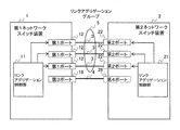
図1は、ネットワークスイッチ装置を含む通信システムの一例を示す図である。 FIG. 1 is a diagram illustrating an example of a communication system including a network switch device.
通信システムは、通信装置である第1のネットワークスイッチ装置1と、通信装置である第2のネットワークスイッチ装置2と、これらの間を接続する複数のリンク3及び4とを含む。第1のネットワークスイッチ装置1は、フレームを中継するネットワーク中継装置であり、リンクアグリゲーション制御部11と、複数の第1ポート12と、第3ポート18とを含む。第2のネットワークスイッチ装置2は、フレームを中継するネットワーク中継装置であり、リンクアグリゲーション制御部21と、複数の第2ポート22と、第4ポート28とを含む。
The communication system includes a first
複数の第1ポート12は、各々、リンク3により、複数の第2ポート22と接続される。リンク3は、例えばケーブルや光ファイバ等の伝送経路である。複数の第1ポート12の数及び複数の第2ポート22の数は、「3」に限られない。
The plurality of
通信システムは、LAG5を使用して、第1のネットワークスイッチ装置1と第2のネットワークスイッチ装置2との間において通信を行う。なお、以下の説明において、「リンクアグリゲーショングループ(Link Aggregation Group)」をLAGと言うこととする。LAG5は、リンクアグリゲーションによる通信におけるリンクの単位である。LAG5は、第1のネットワークスイッチ装置1の複数の第1ポート12と第2のネットワークスイッチ装置2の複数の第2ポート22とを接続する複数のリンク3を含む仮想的な1個のリンクである。
The communication system performs communication between the first
LAG5を用いる通信は、リンクアグリゲーション制御部11及びリンクアグリゲーション制御部21により制御される。LAG5を用いる通信は、例えばリンクアグリゲーション制御プロトコル(LACP)に従って行われる通信である。リンクアグリゲーション制御プロトコルは、例えばIEEE802.3adにより規定されている。従って、リンクアグリゲーション制御部11及びリンクアグリゲーション制御部21が、リンクアグリゲーション制御プロトコルに従ってLAG5を制御することにより、LAG5を用いる通信が実行される。
Communication using the
一方、第3ポート18は、第1のネットワークスイッチ装置1に含まれるポートであって、複数の第1ポート12以外のポートである。第3ポート18は、複数の第1ポート12と複数の第2ポート22とを接続するLAG5に属さないポートである。
On the other hand, the
第4ポート28は、第2のネットワークスイッチ装置2に含まれるポートであって、複数の第2ポート22以外のポートである。第4ポート28は、複数の第1ポート12と複数の第2ポート22とを接続するLAG5に属さないポートである。
The
第3ポート18はリンク4により第4ポート28と接続される。リンク4は、例えばケーブルや光ファイバ等の伝送経路である。第3ポート18の数及び第4ポート28の数は、「1」に限られず、複数であっても良い。複数の第3ポート18及び複数の第4ポート28が設けられる場合、複数の第3ポート18と複数の第4ポート28とを接続する複数のリンクを、第1ポート12及び第2ポート22が属するLAG5以外のリンクアグリゲーショングループとして使用するようにしても良い。
The
なお、第3ポート18は、第2のネットワークスイッチ装置2以外の通信装置と接続されるようにしても良い。第4ポート28は、第1のネットワークスイッチ装置1以外の通信装置と接続されるようにしても良い。
The
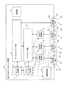
図2は、ネットワークスイッチ装置の構成の一例を示す図である。 FIG. 2 is a diagram illustrating an example of the configuration of the network switch device.
第1のネットワークスイッチ装置1は、リンクアグリゲーション制御部11と複数の第1ポート12と第3ポート18に加えて、データスイッチング部13と、アグリゲータ部14と、送受信制御部15と、電源制御部16と、監視部17とを含む。リンクアグリゲーション制御部11は、スイッチ管理部111と、アグリゲーション制御部112とを含む。複数の第1ポート12は、各々、MAC部121と、PHYモジュール122と、LED(Light Emitting Diode)123とを含む。第3ポート18は、MAC部181と、PHYモジュール182と、LED183とを含む。第3ポート18は、第1ポート12と同様の構成を有していても良く、第1ポート12と異なる構成を有していても良い。
The first
次に、第2のネットワークスイッチ装置2は、例えば第1のネットワークスイッチ装置1と同様の構成を有する。第2ポート22は第1ポート12と同様の構成を有し、第4ポート28は第3ポート18と同様の構成を有する。第2のネットワークスイッチ装置2が、第1のネットワークスイッチ装置1と異なる構成を有するようにしても良い。
Next, the second
例えば、第1のネットワークスイッチ装置1のスイッチ管理部111と第2のネットワークスイッチ装置2のスイッチ管理部111とを区別する場合、第1のネットワークスイッチ装置1のスイッチ管理部を「111A」と表し、第2のネットワークスイッチ装置2のスイッチ管理部を「111B」と表すこととする。換言すれば、第1のネットワークスイッチ装置1の要素には符号Aを付して表し、第2のネットワークスイッチ装置2の要素には符号Bを付して表すこととする。
For example, when distinguishing the switch management unit 111 of the first
PHYモジュール122は、送受信を行なう送受信フレームについて、ネットワークにおける機能を階層的に表したOSI参照モデルの第7階層のうち第1層目に位置する物理層においてデータの送受信及び信号変換を行う物理デバイスである。PHYモジュール122の実装位置は、ポート番号で示される。ポート番号は、第1のネットワークスイッチ装置1において第1ポート12を一意に識別する識別情報である。PHYモジュール122は、ケーブルや光ケーブル等を介して受信した受信フレームをMAC部121に送信する。また、PHYモジュール122は、MAC部121からの送信フレームをケーブルや光ケーブルを介して宛先のPHYモジュールに送信する。PHYモジュール182も同様である。
The
MAC部121は、PHYモジュール122に対応して設けられ、送受信フレームの伝送制御を行う。伝送制御としては、例えば、フレーム形式の検出や誤り検出等が行われる。MAC部181も同様である。
The
MAC部121は、PHYモジュール122からの受信フレームを送受信制御部15に送信する。また、MAC部121は、送受信制御部15からの送信フレームをPHYモジュール122に送信する。一方、MAC部181は、PHYモジュール182からの受信フレームをデータスイッチング部13に送信する。また、MAC部181は、データスイッチング部13からの送信フレームをPHYモジュール182に送信する。
The
LED123は、アグリゲーション制御部112の制御に従って、第1ポート12の状態を点灯を行なうことにより表示する。例えば、第1ポート12がリンクアップしている場合は「緑」、リンクダウンしている場合は「消灯」、エラーである場合は「橙点滅」により、各々の状態が表示される。LED183も同様である。
LED123 displays the state of the
電源制御部16は、複数のPHYモジュール122及びPHYモジュール182への電源供給を制御する。具体的には、電源制御部16は、スイッチ管理部111からの制御に従って、複数のPHYモジュール122及びPHYモジュール182に電源を供給し、また、電源の供給を切断する。
The
送受信制御部15は、MAC部121に対応して設けられるコントローラ、パーサー、マルチプレクサ等である。送受信制御部15は、MAC部121からLACPフレームを受信した場合には、LACPフレームをアグリゲーション制御部112に送信する。また、送受信制御部15は、MAC部121からLACPフレーム以外のフレームを受信した場合には、LACPフレーム以外のフレームをアグリゲータ部14に送信する。更に、送受信制御部15は、アグリゲータ部14から送信されたフレームを、対応するMAC部121にそのまま送信する。
The transmission /
アグリゲータ部14は、LAG5毎に設けられる。アグリゲータ部14は、対応する第1ポート12からの受信フレームを、データスイッチング部13に送信する。また、アグリゲータ部14は、データスイッチング部13からの送信フレームを、LAG5に属する第1ポート12に、予め定められた通信プロトコルに従って分散するように送信する。
The aggregator unit 14 is provided for each
データスイッチング部13は、フレームのスイッチングを行う。換言すれば、データスイッチング部13は、アグリゲータ部14から受信したフレームにおける送信先MACに基づいて、送信先のアグリゲータ部14を決定し、受信したフレームを決定した送信先のアグリゲータ部14に送信する。
The
監視部17は、監視対象である複数の第1ポート12の各々から収集した使用帯域情報を保持する。使用帯域情報としては、例えば、複数の第1ポート12毎の送受信量、LAG5の送受信量、複数の第1ポート12毎のエラー回数、LAG5のエラー回数がある。また、監視部17は、監視対象である第3ポート18から収集した使用帯域情報を保持する。使用帯域情報としては、例えば、第3ポート18の送受信量、第3ポート18のエラー回数がある。なお、複数のLAG5が存在する場合、送受信量やエラー回数は、リンクアグリゲーショングループ毎に収集される。
The monitoring unit 17 holds used bandwidth information collected from each of the plurality of
スイッチ管理部111は、後述するポート状態管理テーブル113を用いて、第1のネットワークスイッチ装置1に含まれる複数の第1ポート12及び第3ポート18の各々を管理する。具体的には、スイッチ管理部111は、複数の第1ポート12及び第3ポート18の各々に実装されたPHYモジュール122及び182を監視する。そして、スイッチ管理部111は、監視の結果に基づいて、伝送路状態(リンクステータス)を判断し、また、アグリゲーション制御部112からの依頼に応じて、電源制御部16を介してPHYモジュール122及び182の電源供給を制御する。
The switch management unit 111 manages each of the plurality of
アグリゲーション制御部112は、後述するLAG管理テーブル114を用いて、LAG5を管理する。具体的には、アグリゲーション制御部112は、LAG5に必要な情報であるリンクアグリゲーション情報を、LACPフレームを用いて他のアグリゲーション制御部112と交換する。LACPフレームは、前述のリンクアグリゲーション制御プロトコルに従うフレームである。
The
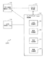
図3は、リンクアグリゲーション制御部の構成の一例を示す図である。 FIG. 3 is a diagram illustrating an example of a configuration of the link aggregation control unit.
リンクアグリゲーション制御部11は、スイッチ管理部111と、アグリゲーション制御部112と、ポート状態管理テーブル113と、LAG管理テーブル114とを含む。アグリゲーション制御部112は、LAG監視部115と、削除処理部116と、追加処理部117と、更新処理部118とを含む。
The link
なお、リンクアグリゲーション制御部21は、リンクアグリゲーション制御部11と同様の構成を有する。例えば、リンクアグリゲーション制御部11のアグリゲーション制御部112とリンクアグリゲーション制御部21のアグリゲーション制御部112とを区別する場合には、リンクアグリゲーション制御部11のアグリゲーション制御部を「112A」と表し、リンクアグリゲーション制御部21のアグリゲーション制御部を「112B」と表すこととする。換言すれば、リンクアグリゲーション制御部11の要素には符号Aを付して表し、リンクアグリゲーション制御部21の要素には符号Bを付して表すこととする。
The link
アグリゲーション制御部112は、自己の属する第1のネットワークスイッチ装置1がリンクアグリゲーション制御におけるマスタ装置である場合に、LAG5を監視した結果に基づいて、LAG5のリンクの削除処理又は追加処理を実行する。リンクアグリゲーション制御におけるマスタ装置は、ECO処理モードにおいて、LAG5のリンクの数を減少又は増加させる。LAG5の監視は、LAG監視部115により実行される。LAG5のリンクの削除処理は、削除処理部116により実行される。LAG5のリンクの追加処理は、追加処理部117により実行される。
When the first
また、アグリゲーション制御部112は、自己の属する第1のネットワークスイッチ装置1がリンクアグリゲーション制御におけるスレーブ装置である場合に、マスタ装置である第2のネットワークスイッチ装置2によるLAG5のリンクの削除処理の結果又は追加処理の結果に従って、LAG5のリンクの更新処理を実行する。リンクアグリゲーション制御におけるスレーブ装置は、ECO処理モードにおいて、マスタ装置によるLAG5のリンクの数を削除処理又は増加処理に従う。マスタ装置によるリンクの削除処理の結果又は追加処理の結果に従うリンクの更新処理は、更新処理部118により実行される。
Further, the
図1〜図3の例においては、第1のネットワークスイッチ装置1がリンクアグリゲーション制御におけるマスタ装置であり、第2のネットワークスイッチ装置2がリンクアグリゲーション制御におけるスレーブ装置である。ネットワークスイッチ装置1及び2のいずれをマスタ装置とするかは、LAG管理テーブル114において予め定められる。LAG管理テーブル114については、図4を参照して後述する。
In the example of FIGS. 1 to 3, the first
アグリゲーション制御部112は、LAG5の使用帯域情報に基づいて、必要なリンクの数を算出し、必要なリンクの数とLAG5に現在リンクアップしているリンクの数とを比較する。LAG5の使用帯域情報は、監視部17から取得される。そして、アグリゲーション制御部112は、必要なリンクの数とLAG5に現在リンクアップしているリンクの数との比較の結果に基づいて、必要なリンクの数が現在リンクアップしているリンクの数より少ない場合に、リンクの削除処理としてリンクダウン処理を実行する。また、アグリゲーション制御部112は、必要なリンクの数とLAG5に現在リンクアップしているリンクの数との比較の結果に基づいて、必要なリンクの数が現在リンクアップしているリンクの数より多い場合に、リンクの追加処理としてリンクアップ処理を実行する。
The
アグリゲーション制御部112は、LAG5の使用帯域情報に基づいて、LAG5のリンクの削除処理を実行する。具体的には、アグリゲーション制御部112は、複数の第1ポート12の中の少なくとも1個の第1ポート12の電源供給を切断するとともにリンクダウン処理を行なう。
The
第1ポート12の電源供給の切断と第1ポート12のリンクダウン処理とは、いずれを先に実行しても良い。図3の例においては、アグリゲーション制御部112は、少なくとも1個の第1ポート12の電源供給を切断することにより、少なくとも1個の第1ポート12のリンクダウン処理を行なう。
Either the power supply cut-off of the
アグリゲーション制御部112は、リンクダウン処理の後に、第2のネットワークスイッチ装置2にリンクダウン処理を終了した旨のリンクダウン終了通知を送信する。リンクダウン終了通知を受信した第2のネットワークスイッチ装置2は、複数の第2ポート22の中のリンクダウンしている少なくとも1個の第2ポート22の電源供給を切断する。これにより、リンクの両端の第1ポート21及び第2ポート22の電源供給を切断することができる。
After the link-down process, the
アグリゲーション制御部112は、使用帯域情報に基づいて電源供給を切断された少なくとも1個の第1ポート12を、リンクダウンを示すエラー通知の対象から除外する。これにより、第1のネットワークスイッチ装置1において、使用帯域情報に基づいて電源供給を切断されたことに起因するリンクダウンとエラーの発生による本来のリンクダウンとを区別することができる。エラー通知の対象とするか否かは、ポート状態管理テーブル113において設定される。ポート状態管理テーブル113については、図5を参照して後述する。
The
第2のネットワークスイッチ装置2において、アグリゲーション制御部112Bは、使用帯域情報に基づいて電源供給を切断されたことによりリンクダウンした第1ポート12にケーブル等を介して接続される第2ポート22を、リンクダウンを示すエラー通知の対象から除外する。これにより、第2のネットワークスイッチ装置2において、使用帯域情報に基づいて電源供給を切断されたことに起因するリンクダウンとエラーの発生による本来のリンクダウンとを区別することができる。
In the second
アグリゲーション制御部112は、リンクの削除処理、換言すれば、リンクダウン処理に先立って、第2のネットワークスイッチ装置2にリンクダウン開始通知を送信する。リンクダウン開始通知を受信した第2のネットワークスイッチ装置2は、全ての第2ポート22の電源を一旦投入し、リンクダウン開始通知に対する応答をアグリゲーション制御部112に返信する。リンクダウン開始通知に対する応答を受信したアグリゲーション制御部112は、リンクダウン処理を実行する。
The
これにより、複数の第2ポート22の全ての電源が一旦投入され、リンクアップされなかったリンクの第2ポート22のみについて電源が切断される。このため、アグリゲーション制御部112における第1ポート12のリンクダウン処理とは独立に、第2のネットワークスイッチ装置2における第2ポート22のリンクダウン処理を実行することができる。また、ユーザやネットワーク監視装置によるアグリゲーション制御部112における第1ポート12の監視に基づいて、第2のネットワークスイッチ装置2における第2ポート22をユーザがリンクダウンする必要を無くすことができる。
Thereby, all the power supplies of the plurality of
アグリゲーション制御部112は、LAG5の使用帯域情報に基づいて、LAG5のリンクの追加処理を実行する。具体的には、アグリゲーション制御部112は、複数の第1ポート12の中の少なくとも1個の第1ポート12の電源を投入するとともに第1ポート12をリンクアップする。なお、リンクアップされる第1ポート12は、電源を投入されたポートである。
The
アグリゲーション制御部112は、リンクアップ処理の終了後に、第2のネットワークスイッチ装置2にリンクアップ終了通知を送信する。リンクアップ終了通知を受信した第2のネットワークスイッチ装置2は、複数の第2ポート22の中のリンクダウンしている第2ポート22の電源供給を切断する。これにより、リンクの両端の第1ポート21及び第2ポート22の電源供給を切断することができる。
The
アグリゲーション制御部112は、リンクの追加処理の開始に先立って、第2のネットワークスイッチ装置2にリンクアップ開始通知を送信する。リンクアップ開始通知を受信した第2のネットワークスイッチ装置2は、一旦、全ての第2ポート22の電源を投入し、リンクアップ開始通知に対する応答をアグリゲーション制御部112に返信する。リンクアップ開始通知に対する応答を受信したアグリゲーション制御部112は、リンクアップ処理を実行する。
The
これにより、複数の第2ポート22について一旦全ての電源が投入され、リンクアップされなかったリンクの第2ポート22のみについて電源が切断される。このため、アグリゲーション制御部112における第1ポート12のリンクアップとは独立に、第2のネットワークスイッチ装置2における第2ポート22のリンクアップ処理を実行することができる。また、ユーザやネットワーク監視装置によるアグリゲーション制御部112における第1ポート12の監視に基づいて、第2のネットワークスイッチ装置2における第2ポート22をリンクアップする必要を無くすことができる。
As a result, all the power is temporarily turned on for the plurality of
アグリゲーション制御部112は、リンクアップ処理及びリンクダウン処理において、LA−ECOフレームを生成して使用する。LA−ECOフレームは、ポートの電源供給を切断して消費電力を削減するためのフレーム、換言すれば、後述するECO処理モードを実現するフレームである。具体的には、LA−ECOフレームは、LACPフレームの一種であって、リンクアップ開始通知、リンクアップ終了通知、リンクダウン開始通知、リンクダウン終了通知のためのフレームである。また、LA−ECOフレームは、リンクアップ開始通知に対する応答、リンクアップ終了通知に対する応答、リンクダウン開始通知に対する応答、リンクダウン終了通知に対する応答としても使用される。
The
例えば、フレームに含まれる複数のOCTETの中の予め定められた位置の1又は複数のOCTET(以下、特定OCTETという)が、そのフレームがLA−ECOフレームであるか否かを表すために用いられる。換言すれば、LA−ECOフレームの特定OCTETは、予め定められた値を有する。更に、LA−ECOフレームの特定OCTETの値に基づいて、そのフレームは、リンクアップ開始通知、リンクアップ終了通知、リンクダウン開始通知、リンクダウン終了通知、又は、これらの応答のいずれかであると判断される。LA−ECOフレームについては、図6を参照して後述する。 For example, one or more OCCTETs (hereinafter referred to as specific OCTETs) at predetermined positions in a plurality of OCCTETs included in a frame are used to indicate whether or not the frame is an LA-ECO frame. . In other words, the specific OCTET of the LA-ECO frame has a predetermined value. Further, based on the value of the specific OCTET of the LA-ECO frame, the frame is one of a link-up start notification, a link-up end notification, a link-down start notification, a link-down end notification, or a response thereof. To be judged. The LA-ECO frame will be described later with reference to FIG.
アグリゲーション制御部112は、自己の属する第1のネットワークスイッチ装置1がリンクアグリゲーション制御におけるマスタ装置である場合に、LAG5を監視の結果に基づいて、LAG5のリンクアップするポート(換言すれば、リンク)の交替処理を実行する。具体的には、アグリゲーション制御部112は、LAG5の使用帯域情報に基づいて、現在リンクアップしているポートについて、リンクアップしている時間が予め定められた閾値を超えているかを判断する。リンクアップしている時間は、後述するように、ポート状態管理テーブル113における「リンクアップ稼働時間」である。
When the first
そして、アグリゲーション制御部112は、リンクアップしている時間が閾値を超えているポートが存在する場合に、リンクアップ処理を実行した後におけるリンクアップしている時間が閾値を超えているポートについて、リンクダウン処理を実行する。また、アグリゲーション制御部112は、リンクダウン処理の対象となるポートの数と同一の数のポートを、リンクダウンしている複数のポートの中から選択して、選択したポートについてリンクアップ処理を実行する。
And, when there is a port whose link up time exceeds the threshold, the
上記のポートの交代処理により、LAG5において、リンクアグリゲーショングループにおいて確保された使用帯域が余剰である場合であっても、特定のリンクがリンクダウンして電源が切断されたままとなることを防止することができる。例えば、特定のリンクがリンクダウンして電源が切断されたままである場合、その特定のリンクにおいてハードウェア故障等が発生しても、LAG5において使用帯域が不足してその特定のリンクをリンクアップするまで、ハードウェア故障等を検出することができない。しかし、特定のリンクが電源供給を切断され続けることを防止することができるので、随時ハードウェア故障等を検出することができ、瞬間的な帯域の不足を生じることを防止することができる。また、特定のリンクの部品のみの使用時間が増加することを防止して、ハードウェア故障を平準化することができる。
The above-described port replacement process prevents the specific link from being linked down and the power supply from being cut off even when the used bandwidth reserved in the link aggregation group is excessive in LAG5. be able to. For example, when a specific link is linked down and the power supply is cut off, even if a hardware failure or the like occurs in the specific link, the use band is insufficient in the
図4は、LAG管理テーブルの一例を示す図である。 FIG. 4 is a diagram illustrating an example of the LAG management table.
LAG管理テーブル114は、項目毎にLAG5の現在の状況を示す情報を格納する。LAG5の状況を管理する項目としては、「Actor System ID」「Actor Aggregation Key」「Partner System ID」「Partner Aggregation Key」「PORT」「Actor ECO処理モード」「Partner ECO処理モード」「ECO処理役割」「ECO処理実行フラグ」「送信OCTET数」「受信OCTET数」がある。
The LAG management table 114 stores information indicating the current status of the
ここで、「Actor」は、自スイッチについての項目であることを示す。「Partner」は、接続先スイッチについての項目であることを示す。従って、第1のネットワークスイッチ装置1に設けられるLAG管理テーブル114においては、「Actor」は第1のネットワークスイッチ装置1を意味し、「Partner」は第2のネットワークスイッチ装置2を意味する。
Here, “Actor” indicates that the item is related to the own switch. “Partner” indicates an item for the connection destination switch. Therefore, in the LAG management table 114 provided in the first
「Actor System ID」は、自スイッチ、換言すれば、第1のネットワークスイッチ装置1において、LAG5が使用するMACアドレスである。「Actor Aggregation Key」は、自スイッチ、換言すれば、第1のネットワークスイッチ装置1において、LAG5を識別する識別情報である。
The “Actor System ID” is a MAC address used by the
「Partner System ID」は、第1のネットワークスイッチ装置1のLAG5の接続先スイッチ、換言すれば、第2のネットワークスイッチ装置2のLAG5が使用するMACアドレスである。「Partner Aggregation Key」は、接続先スイッチ、換言すれば、第2のネットワークスイッチ装置2において、LAG5を識別する識別情報である。
The “Partner System ID” is a MAC address used by the connection destination switch of the
「PORT」は、自スイッチ、換言すれば、第1のネットワークスイッチ装置1においてLAG5に参加している第1ポート12のポート番号である。
“PORT” is the port number of the
「Actor ECO処理モード」は、自スイッチ、換言すれば、第1のネットワークスイッチ装置1のLAG5においてECO処理モードが有効であるか無効であるかを示す。「Partner ECO処理モード」は、接続先スイッチ、換言すれば、第2のネットワークスイッチ装置2のLAG5においてECO処理モードが「有効」であるか「無効」であるかを示す。
The “Actor ECO processing mode” indicates whether the ECO processing mode is valid or invalid in the self switch, in other words, the
ここで、「ECO処理モード」は、ポートの電源供給を切断して消費電力を削減するモード、換言すれば、LA−ECOフレームにより実現されるモードである。従って、第1のネットワークスイッチ装置1は、「Actor ECO処理モード」が「有効」である場合にはECO状態とされ、「Actor ECO処理モード」が「無効」である場合にはECO状態以外の状態、換言すれば、通常の状態とされる。ECO状態については、図5を参照して後述する。第2のネットワークスイッチ装置2は、「Partner ECO処理モード」が「有効」である場合にはECO状態とされ、「Partner ECO処理モード」が「無効」である場合にはECO状態以外の状態、換言すれば、通常の状態とされる。
Here, the “ECO processing mode” is a mode in which the power supply to the port is cut off to reduce power consumption, in other words, a mode realized by the LA-ECO frame. Therefore, the first
「ECO処理役割」は、ECO処理モードにおいて、自スイッチ、換言すれば、第1のネットワークスイッチ装置1がマスタ装置であるかスレーブ装置であるかを示す。第1のネットワークスイッチ装置1がマスタ装置である場合、ECO処理役割は「MASTER」とされる。これにより、第1のネットワークスイッチ装置1は、使用帯域情報に基づいて、ECO処理モードにおいて、LAG5のリンクの数を増加又は減少させる。第1のネットワークスイッチ装置1がスレーブ装置である場合、ECO処理役割は「SLAVE」とされる。これにより、第1のネットワークスイッチ装置1は、ECO処理モードにおいて、マスタ装置である第2のネットワークスイッチ装置2が実行するECO処理に追従する。
The “ECO processing role” indicates whether the local switch, in other words, the first
「ECO処理実行フラグ」は、自スイッチ、換言すれば、第1のネットワークスイッチ装置1がECO処理を実行中であるか停止中であるかを示す。換言すれば、「ECO処理実行フラグ」により、第1のネットワークスイッチ装置1がECO処理モードであるか否かが示される。
The “ECO processing execution flag” indicates whether the switch itself, in other words, the first
「送信OCTET数」は、LAG5を介して送信されたOCTETの数である。「受信OCTET数」は、LAG5を介して受信されたOCTETの数である。 “Number of transmitted OCTETs” is the number of OCTEETs transmitted via LAG5. The “number of received OCTETs” is the number of OCTETs received via LAG5.
LAG管理テーブル114は、アグリゲーション制御部112により作成される。LAG管理テーブル114において、「Actor System ID」、「Actor Aggregation Key」、「Partner System ID」、「Partner Aggregation Key」及び「PORT」は、LAG5を構成する際に、例えば第1又は第2ネットワーク装置に接続するコンピュータから、アグリゲーション制御部112にそれぞれ入力される。「Actor ECO処理モード」、「Partner ECO処理モード」、「ECO処理役割」及び「ECO処理実行フラグ」は、ECO処理モードを実行する際に、アグリゲーション制御部112によりそれぞれ設定される。「送信OCTET数」及び「受信OCTET数」は、ECO処理モードにおいて、監視部17から「送信OCTET数」及び「受信OCTET数」を取得したアグリゲーション制御部112により設定される。
The LAG management table 114 is created by the
リンクアグリゲーション制御部11は、LAG5を管理するLAG管理テーブル114Aを含む。第1のネットワークスイッチ装置1において、LAG管理テーブル114Aには、第1のネットワークスイッチ装置1がマスタ装置として登録され、第2のネットワークスイッチ装置2がスレーブ装置として登録される。これにより、マスタ装置である第1のネットワークスイッチ装置1のアグリゲーション制御部112Aは、LAG5に属する複数のポートについてのリンクダウン処理及びリンクアップ処理を実行するか否かについて、それぞれ決定を行なう。
The link
リンクアグリゲーション制御部21は、LAG5を管理するLAG管理テーブル114Bを含む。第2のネットワークスイッチ装置2において、LAG管理テーブル114Bには、第1のネットワークスイッチ装置1がマスタ装置として登録され、第2のネットワークスイッチ装置2がスレーブ装置として登録される。これにより、スレーブ装置である第2のネットワークスイッチ装置2のアグリゲーション制御部112Bは、マスタ装置である第1のネットワークスイッチ装置1によるLAG5のリンクの削除処理の結果又は追加処理の結果に従って、LAG5のリンクの更新処理を実行する。
The link
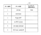
図5は、ポート状態管理テーブルの一例を示す図である。 FIG. 5 is a diagram illustrating an example of the port state management table.
ポート状態管理テーブル113は、ポート毎にポートの状態を示す情報を格納する。ポート状態管理テーブル113において、ポートはポート番号により表される。なお、図5においては、LAG5に属するポートがポート番号1〜6までの6個存在し、6個のポートが各々異なるポート状態であるものとする。
The port status management table 113 stores information indicating the port status for each port. In the port status management table 113, the port is represented by a port number. In FIG. 5, it is assumed that there are six ports belonging to LAG5 from
ポート状態を示す情報としては、「Link Up」、「Link Down」、「Power OFF」、「no PHY module」、「Link state unknown」及び「ECO auto−poweroff」がある。 Information indicating the port status includes “Link Up”, “Link Down”, “Power OFF”, “no PHY module”, “Link state unknown”, and “ECO auto-poweroff”.
「Link Up」は、ポートがリンクアップしていることを示す。ポート状態がリンクアップである場合には、リンクアップ稼働時間も格納される。リンクアップ稼働時間は、ポートがリンクアップしてから稼動を継続している時間である。リンクアップ稼働時間の単位は、例えば秒である。 “Link Up” indicates that the port is linked up. When the port state is link up, the link up operation time is also stored. The link up operation time is the time during which the port continues to operate after the link up. The unit of the link up operation time is, for example, second.
「Link Down」は、ポートがリンクダウンしていることを示す。「Power OFF」は、ポートの電源供給が切断されていることを示す。「no PHYmodule」は、ポートのPHYモジュールが認識できない等、PHYモジュールの状態が不明であることを示す。「Link state unknown」は、ポートのリンクの状態が不明であることを示す。 “Link Down” indicates that the port is linked down. “Power OFF” indicates that the power supply of the port is cut off. “No PHYmodule” indicates that the state of the PHY module is unknown, for example, the port PHY module cannot be recognized. “Link state unknown” indicates that the link state of the port is unknown.
「ECO auto−poweroff」は、ポートがECO状態であることを示す。「ECO auto−poweroff」、換言すれば、ECO状態は、消費電力の削減のために、ポートの電源供給が切断されていることを示す。従って、ポートがECO状態である場合には、ポートはリンクダウンしているが、リンクダウンの原因はハードウェア故障や回線障害等ではなく、消費電力の削減のためにポートの電源供給が切断されたことが判別できる。 “ECO auto-poweroff” indicates that the port is in the ECO state. “ECO auto-poweroff”, in other words, the ECO state indicates that the power supply of the port is cut to reduce power consumption. Therefore, when the port is in the ECO state, the port is linked down, but the cause of the link down is not a hardware failure or a line failure, but the power supply of the port is cut to reduce power consumption. Can be determined.
ポート状態管理テーブル113は、スイッチ管理部111により作成される。ポート状態管理テーブル113において、「Link Up」、「Link Down」、「Power OFF」及び「no PHY module」は、スイッチ管理部111により更新される。また、「Link Up」、「Link Down」、「Link state unknown」及び「ECO auto−poweroff」は、後述するように、アグリゲーション制御部112の依頼に基づいて、スイッチ管理部111により、予め定められたタイミングで更新される。
The port state management table 113 is created by the switch management unit 111. In the port status management table 113, “Link Up”, “Link Down”, “Power OFF”, and “no PHY module” are updated by the switch management unit 111. In addition, “Link Up”, “Link Down”, “Link state unknown”, and “ECO auto-poweroff” are determined in advance by the switch management unit 111 based on the request of the
リンクアグリゲーション制御部11は、第1ポート12の状態を管理するポート状態管理テーブル113Aを含む。第1のネットワークスイッチ装置1において、ポート状態管理テーブル113Aには、使用帯域情報に基づいて電源供給を切断された少なくとも1個の第1ポート12の状態が、ECO状態、換言すれば、「ECO auto−poweroff」として登録される。ECO状態は、消費電力を削減するためにポートの電源供給を切断した状態であって、LA−ECOフレームにより実現される状態であり、使用帯域情報に基づかない電源の切断と区別される。これにより、アグリゲーション制御部112Aは、ポート状態管理テーブル113AにECO状態として登録された少なくとも1個の第1ポート12についてのリンクダウンの発生を、エラー通知の対象から除外する。
The link
リンクアグリゲーション制御部21は、第2ポート22の状態を管理するポート状態管理テーブル113Bを含む。第2のネットワークスイッチ装置2において、ポート状態管理テーブル113Bには、使用帯域情報に基づいて電源供給を切断された少なくとも1個の第1ポート12のリンクダウンに応じてリンクダウンした少なくとも1個の第2ポート22の状態が、ECO状態、換言すれば、「ECO auto−poweroff」として登録される。これにより、アグリゲーション制御部112Bは、第2ポート状態管理テーブル113BにECO状態として登録された少なくとも1個の第2ポート22についてのリンクダウンを、エラー通知の対象から除外する。
The link
図6は、LA−ECOフレームの一例を示す図である。実際には、図6は、LA−ECOフレーム、換言すれば、ECO状態通知フレームにおける、各フィールドと、各フィールドのOCTETの数と、各フィールドに格納される情報についての説明を示す。 FIG. 6 is a diagram illustrating an example of an LA-ECO frame. Actually, FIG. 6 shows an explanation of each field, the number of OCTET of each field, and information stored in each field in the LA-ECO frame, in other words, the ECO status notification frame.
「Destination Address」は、LA−ECOフレームの送信先MACアドレスを格納するフィールドである。「Source Address」は、LA−ECOフレームの送信元MACアドレスを格納するフィールドである。「Length/Type」は、LA−ECOフレームがLA−ECOフレームであることを示すType値を格納するフィールドである。「Subtype」は、図1及び図2の例のネットワークスイッチ装置1及び2においては使用されないフィールドである。「Version Number」は、リンクアグリゲーション制御プロトコルの版数を格納するフィールドである。
“Destination Address” is a field for storing the destination MAC address of the LA-ECO frame. “Source Address” is a field for storing the source MAC address of the LA-ECO frame. “Length / Type” is a field for storing a Type value indicating that the LA-ECO frame is an LA-ECO frame. “Subtype” is a field that is not used in the
「Actor System」は、自スイッチ、換言すれば、第1のネットワークスイッチ装置1のLAG5のMACアドレスを格納するフィールドである。従って、「Actor System」は、図4のLAG管理テーブル114に格納された「Actor System ID」を格納する。「Actor Key」は、自スイッチ、換言すれば、第1のネットワークスイッチ装置1において、LAG5を識別する識別情報を格納するフィールドである。従って、「Actor Key」は、図4のLAG管理テーブル114に格納された「Actor Aggregation Key」を格納する。
“Actor System” is a field that stores the MAC address of the
「Partner System」は、LAG5において第1のネットワークスイッチ装置1の接続先スイッチ、換言すれば、LAG5において第2のネットワークスイッチ装置2が使用するMACアドレスを格納するフィールドである。従って、「Partner System」は、図4のLAG管理テーブル114に格納された「Partner System ID」を格納する。「Partner Key」は、接続先スイッチ、換言すれば、第2のネットワークスイッチ装置2において、LAG5を識別する識別情報を格納するフィールドである。従って、「Partner Key」は、図4のLAG管理テーブル114に格納された「Partner Aggregation Key」を格納する。
“Partner System” is a field for storing a connection destination switch of the first
「ECO mode」は、フレームがLA−ECOフレームであるか否かを示す情報を格納するフィールドである。「ECO mode」の値が「1」である場合、フレームはLA−ECOフレームであり、従って、ECO処理モードは有効である。「ECO mode」の値が「0」である場合、ECO処理モードは無効である。「Link Training」は、ECO処理モードにおいて、リンクを行なうポートを変更中であるか否かを示す情報を格納するフィールドである。「Link Training」の値が「1」である場合、第1のネットワークスイッチ装置1がリンクを行なうポートを変更中である旨を示す。「Link Training」の値が「0」である場合、第1のネットワークスイッチ装置1はリンクを行なうポートを変更中ではない旨を示す。
“ECO mode” is a field for storing information indicating whether or not the frame is an LA-ECO frame. If the value of “ECO mode” is “1”, the frame is an LA-ECO frame, and therefore the ECO processing mode is valid. When the value of “ECO mode” is “0”, the ECO processing mode is invalid. “Link Training” is a field for storing information indicating whether or not the port to be linked is being changed in the ECO processing mode. When the value of “Link Training” is “1”, it indicates that the first
「ACK」及び「NACK」は、各々、先に受信したフレームに対する応答を格納するフィールドである。「ACK」の値が「1」である場合、先に受信したフレームによる通知を了承することを示す。「NACK」の値が「1」である場合、先に受信したフレームによる通知を却下することを示す。「reserve」は、図1及び図2の例のネットワークスイッチ装置1及び2においては使用されない予約済みフィールドである。「FCS」は、フレームのチェックサムを格納するフィールドである。
“ACK” and “NACK” are fields for storing responses to previously received frames, respectively. When the value of “ACK” is “1”, it indicates that the notification by the previously received frame is acknowledged. When the value of “NACK” is “1”, it indicates that the notification by the previously received frame is to be rejected. “Reserve” is a reserved field that is not used in the
以下、図7A〜図13を参照して、アグリゲーション制御部112について詳細に説明する。
Hereinafter, the
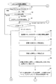
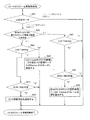
図7A及び図7Bは、一体となって、第1のネットワークスイッチ装置1のアグリゲーション制御部112Aが実行するリンクアグリゲーション監視処理フローを示す。
FIG. 7A and FIG. 7B show the link aggregation monitoring process flow executed by the aggregation control unit 112A of the first
アグリゲーション制御部112Aにおいて、LAG監視部115Aは、LAG管理テーブル114Aを参照して、「Actor ECO処理モード」及び「Partner ECO処理モード」が有効であるか無効であるかを判断する(ステップS1)。換言すれば、LAG監視部115Aは、「Actor」である第1のネットワークスイッチ装置1及び「Partner」である第2のネットワークスイッチ装置2がECO処理モードであるか否かを判断する。
In the aggregation control unit 112A, the LAG monitoring unit 115A refers to the LAG management table 114A and determines whether the “Actor ECO processing mode” and the “Partner ECO processing mode” are valid or invalid (step S1). . In other words, the LAG monitoring unit 115A determines whether or not the first
LAG管理テーブル114Aにおいて「Actor ECO処理モード」及び「Partner ECO処理モード」が無効である場合、LAG監視部115Aは、予め定められた時間の経過を待って(ステップS110)、ステップS1を繰り返す。 When the “Actor ECO processing mode” and the “Partner ECO processing mode” are invalid in the LAG management table 114A, the LAG monitoring unit 115A waits for elapse of a predetermined time (step S110) and repeats step S1.
LAG管理テーブル114Aにおいて「Actor ECO処理モード」及び「Partner ECO処理モード」が有効である場合、LAG監視部115Aは、LAG管理テーブル114Aを参照して、「ECO処理役割」を判断する(ステップS2)。換言すれば、LAG監視部115Aは、自己が属する第1のネットワークスイッチ装置1がマスタ装置であるか否かを判断する。
When the “Actor ECO processing mode” and the “Partner ECO processing mode” are valid in the LAG management table 114A, the LAG monitoring unit 115A refers to the LAG management table 114A to determine “ECO processing role” (step S2). ). In other words, the LAG monitoring unit 115A determines whether or not the first
「ECO処理役割」が「スレーブ装置(図7Aにおいては、SLAVEと表示)」である場合、LAG監視部115Aは、予め定められた時間の経過を待って(ステップS110)、ステップS1を繰り返す。 When the “ECO processing role” is “slave device (indicated as SLAVE in FIG. 7A)”, the LAG monitoring unit 115A waits for a predetermined time (step S110) and repeats step S1.
「ECO処理役割」が「マスタ装置(図7Aにおいては、MASTERと表示)」である場合、LAG監視部115Aは、LAGチェック状況を格納するLAGチェック状況格納領域を初期化し(ステップS3)、LAG5をサーチする(ステップS4)。換言すれば、ステップS4において、LAG監視部115Aは、リンクアグリゲーション監視処理が未処理のLAG5が存在するか否かを判断する。LAGチェック状況格納領域は、例えばLAG監視部115Aが有するメモリ内に設けられる。
When the “ECO processing role” is “master device (indicated as“ MASTER ”in FIG. 7A)”, the LAG monitoring unit 115A initializes a LAG check status storage area for storing the LAG check status (step S3), and LAG5. Is searched (step S4). In other words, in step S4, the LAG monitoring unit 115A determines whether there is a
リンクアグリゲーション監視処理が未処理のLAG5が存在しない場合、LAG監視部115Aは、予め定められた時間の経過を待って(ステップS110)、ステップS1を繰り返す。 When there is no LAG5 that has not been subjected to link aggregation monitoring processing, the LAG monitoring unit 115A waits for a predetermined time (step S110) and repeats step S1.
リンクアグリゲーション監視処理が未処理のLAG5が存在する場合、LAG監視部115Aは、リンクアグリゲーション監視処理が未処理のLAG5の中から1個のLAG5を選択して、監視部17Aから選択したLAG5についての統計情報を獲得する(ステップS5)。統計情報としては、送信OCTET数と、受信OCTET数とが獲得される。監視部17Aから獲得した送信OCTET数は「現在の送信OCTET数」であり、監視部17から獲得した受信OCTET数は「現在の受信OCTET数」である。「現在の送信OCTET数」及び「現在の受信OCTET数」は、LAGチェック状況格納領域に格納される。 When there is an unprocessed LAG5 for which link aggregation monitoring processing is not performed, the LAG monitoring unit 115A selects one LAG5 from among the LAG5 for which link aggregation monitoring processing has not been processed, and for the LAG5 selected from the monitoring unit 17A. Statistical information is acquired (step S5). As statistical information, the number of transmitted OCTETs and the number of received OCTEETs are acquired. The number of transmission OCETETs acquired from the monitoring unit 17A is the “current number of transmission OCTETs”, and the number of reception OCTETs acquired from the monitoring unit 17 is the “number of current reception OCTETs”. The “current number of transmitted OCTETs” and “current number of received OCETETs” are stored in the LAG check status storage area.
この後、LAG監視部115Aは、送信に必要なリンク数を算出する(ステップS6)。具体的には、LAG監視部115Aは、LAG管理テーブル114Aを参照して、「送信OCTET数」を取得する。LAG管理テーブル114Aから取得した送信OCTET数は「前回の送信OCTET数」である。「前回の送信OCTET数」は、LAGチェック状況格納領域に格納される。この後、LAG監視部115Aは、LAGチェック状況格納領域に格納した値を用いて、{(現在の送信OCTET数)−(前回の送信OCTET数)}を(単位時間当たりの1個のリンクの基準帯域)で割る。これにより、「送信に必要なリンク数」が算出される。単位時間当たりの1個のリンクの基準帯域は、経験的に知ることができ、予め定められる。「送信に必要なリンク数」は、LAGチェック状況格納領域に格納される。 Thereafter, the LAG monitoring unit 115A calculates the number of links necessary for transmission (step S6). Specifically, the LAG monitoring unit 115A refers to the LAG management table 114A and acquires the “number of transmission OCTETs”. The number of transmission OCTETs acquired from the LAG management table 114A is the “number of previous transmission OCTETs”. The “number of previous transmission OCTETs” is stored in the LAG check status storage area. Thereafter, the LAG monitoring unit 115A uses the value stored in the LAG check status storage area to calculate {(current number of transmission OCTETs) − (last number of transmission OCETETs)} (of one link per unit time). Divide by (reference band). Thereby, “the number of links necessary for transmission” is calculated. The reference bandwidth of one link per unit time can be known empirically and is determined in advance. The “number of links necessary for transmission” is stored in the LAG check status storage area.
次に、LAG監視部115Aは、受信に必要なリンク数を算出する(ステップS7)。具体的には、LAG監視部115Aは、LAG管理テーブル114Aを参照して、「受信OCTET数」を取得する。LAG管理テーブル114Aから取得した受信OCTET数は「前回の受信OCTET数」である。「前回の受信OCTET数」は、LAGチェック状況格納領域に格納される。この後、LAG監視部115Aは、LAGチェック状況格納領域に格納した値を用いて、{(現在の受信OCTET数)−(前回の受信OCTET数)}を(単位時間当たりの1個のリンクの基準帯域)で割る。これにより、「受信に必要なリンク数」が算出される。「受信に必要なリンク数」は、LAGチェック状況格納領域に格納される。 Next, the LAG monitoring unit 115A calculates the number of links necessary for reception (step S7). Specifically, the LAG monitoring unit 115A refers to the LAG management table 114A and acquires the “number of received OCTETs”. The number of received OCTETs acquired from the LAG management table 114A is “the previous number of received OCTETs”. The “previous received OCET number” is stored in the LAG check status storage area. Thereafter, the LAG monitoring unit 115A uses the value stored in the LAG check status storage area to calculate {(current received OCETET number) − (previous received OCCTET number)} (one link per unit time). Divide by (reference band). Thereby, “the number of links necessary for reception” is calculated. The “number of links necessary for reception” is stored in the LAG check status storage area.
更に、LAG監視部115Aは、LAGチェック状況格納領域に格納した値を用いて、送信に必要なリンク数と受信に必要なリンク数とを比較して、大きい方をLAG5における「必要なリンク数」とする(ステップS8)。なお、「必要なリンク数」が「0」となった場合には、第1のネットワークスイッチ装置1と第2のネットワークスイッチ装置2との間の通信が全て遮断されるのを防ぐため、「必要なリンク数」を「1」とする。「必要なリンク数」は、LAGチェック状況格納領域に格納される。
Further, the LAG monitoring unit 115A compares the number of links necessary for transmission with the number of links necessary for reception using the value stored in the LAG check status storage area. (Step S8). When the “necessary number of links” is “0”, in order to prevent all communication between the first
この後、LAG監視部115Aは、ポート状態管理テーブル113Aを参照して、LAG5に属する第1ポート12の中で、その時点でリンクアップしている第1ポート12の数を調べる(ステップS9)。換言すれば、LAG監視部115Aは、ポート状態管理テーブル113Aにおいてポート状態が「Link Up」である第1ポート12の数を、「現在のリンク数」として抽出する。「現在のリンク数」は、LAGチェック状況格納領域に格納される。
Thereafter, the LAG monitoring unit 115A refers to the port state management table 113A and checks the number of
この後、LAG監視部115Aは、LAGチェック状況格納領域に格納した値を用いて、「現在のリンク数」が「必要なリンク数」よりも小さいか否かを判断する(ステップS10)。「現在のリンク数」が「必要なリンク数」よりも小さい場合(ステップS10 Yes)、LAG監視部115Aは、第1ポート12の追加処理を実行する(ステップS11)。第1ポート12の追加処理は、実際には、LAG監視部115Aにより起動された追加処理部117Aが実行する。第1ポート12の追加処理については、図8を参照して後述する。ステップS11の後、ステップS14が実行される。
Thereafter, the LAG monitoring unit 115A determines whether the “current number of links” is smaller than the “necessary number of links” using the value stored in the LAG check status storage area (step S10). When the “current number of links” is smaller than the “necessary number of links” (Yes in step S10), the LAG monitoring unit 115A performs the process of adding the first port 12 (step S11). The addition process of the
「現在のリンク数」が「必要なリンク数」以上の場合(ステップS10 No)、LAG監視部115Aは、更に、LAGチェック状況格納領域に格納した値を用いて、「現在のリンク数」が「必要なリンク数」よりも大きいか否かを判断する(ステップS12)。「現在のリンク数」が「必要なリンク数」よりも大きい場合(ステップS12 Yes)、LAG監視部115Aは、第1ポート12の削除処理を実行する(ステップS13)。第1ポート12の削除処理は、実際には、LAG監視部115Aにより起動された削除処理部116Aが実行する。第1ポート12の削除処理については、図9を参照して後述する。ステップS13の後、ステップS14が実行される。
When the “current link count” is equal to or greater than the “necessary link count” (No in step S10), the LAG monitoring unit 115A further uses the value stored in the LAG check status storage area to set the “current link count”. It is determined whether or not it is larger than “the number of necessary links” (step S12). When the “current number of links” is larger than the “necessary number of links” (Yes in step S12), the LAG monitoring unit 115A executes the deletion process of the first port 12 (step S13). The deletion processing of the
「現在のリンク数」が「必要なリンク数」以下の場合(ステップS12 No)、換言すれば、「現在のリンク数」が「必要なリンク数」と等しい場合、LAG監視部115Aは、第1ポート12の交替処理を実行する。具体的には、LAG監視部115Aは、LAG管理テーブル114Aを参照して、LAG5に属する第1ポート12を抽出し(ステップS14)、ポート状態管理テーブル113Aを参照して、LAG5に属する第1ポート12の中で、リンクアップ稼働時間が基準時間を越えている第1ポート12が存在するか否かを判断する(ステップS15)。基準時間は、予め定められる。
If the “current link number” is equal to or less than the “necessary link number” (No in step S12), in other words, if the “current link number” is equal to the “necessary link number”, the LAG
リンクアップ稼働時間が基準時間を越えている第1ポート12が存在しない場合(ステップS15 No)、LAG監視部115Aは、予め定められた時間の経過を待って(ステップS110)、ステップS1を繰り返す。
When there is no
リンクアップ稼働時間が基準時間を越えている第1ポート12が存在する場合(ステップS15 Yes)、LAG監視部115Aは、ポート状態管理テーブル113Aを参照して、LAG5に属する第1ポート12の中で、ポート状態が「ECO auto−poweroff」である第1ポート12が存在するか否かを判断する(ステップS16)。
When there is a
ポート状態が「ECO auto−poweroff」である第1ポート12が存在しない場合(ステップS16 No)、LAG監視部115Aは、予め定められた時間の経過を待って(ステップS110)、ステップS1を繰り返す。
When the
ポート状態が「ECO auto−poweroff」である第1ポート12が存在する場合(ステップS16 Yes)、LAG監視部115Aは、第1ポート12の追加処理を実行する(ステップS17)。前述したように、第1ポート12の追加処理については、図8を参照して後述する。
When there is the
この後、LAG監視部115Aは、LAG5に属する第1ポート12の状態を確認することにより、リンクアップしているリンクの数が「現在のリンク数」よりも増えていることを確認する(ステップS18)。なお、リンクアップしているリンクの数が「現在のリンク数」よりも増えていない場合には、LAG監視部115Aは、ステップS17を繰り返す。この後、LAG監視部115Aは、ステップS15において抽出したリンクアップ稼働時間が基準時間を越えている第1ポート12を指定して、第1ポート12の削除処理を実行する(ステップS19)。前述したように、第1ポート12の削除処理については、図9を参照して後述する。この後、LAG監視部115Aは、ステップS4を繰り返す。
Thereafter, the LAG monitoring unit 115A confirms that the number of links that are linked up is larger than the “current number of links” by confirming the state of the
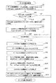
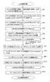
図8は、第1のネットワークスイッチ装置1のアグリゲーション制御部112Aが実行するポート追加処理フローである。
FIG. 8 is a port addition process flow executed by the aggregation control unit 112A of the first
アグリゲーション制御部112Aにおいて、追加処理部117Aは、ポート状態管理テーブル113Aを参照して、LAG5に属する第1ポート12の中で、ポート状態が「ECO auto−poweroff」である第1ポート12を抽出する(ステップS21)。そして、追加処理部117Aは、「ECO auto−poweroff」である第1ポート12の数が「0」であるか「1以上」であるかを判断する(ステップS22)。「ECO auto−poweroff」である第1ポート12の数が「0」である場合、追加処理部117Aは、処理を終了する。
In the aggregation control unit 112A, the additional processing unit 117A refers to the port state management table 113A and extracts the
「ECO auto−poweroff」である第1ポート12の数が「1以上」である場合、追加処理部117Aは、「ECO auto−poweroff」である第1ポート12の中から、新たにリンクアップに追加する第1ポート12を決定する(ステップS23)。リンクアップに追加する第1ポート12は、例えば、「ECO auto−poweroff」である第1ポート12の中からランダムに選択される。
When the number of
この後、追加処理部117Aは、LAG5のリンクの更新処理を実行中であることを示すフレーム、換言すれば、LA−ECOフレームを第2のネットワークスイッチ装置2のアグリゲーション制御部112Bに送信する(ステップS24)。この時、LA−ECOフレームにおいて、「Link Training」が「1」とされる。このLA−ECOフレームは、リンクアップ開始通知である。 Thereafter, the additional processing unit 117A transmits a frame indicating that the LAG5 link update process is being executed, in other words, an LA-ECO frame to the aggregation control unit 112B of the second network switch device 2 ( Step S24). At this time, “Link Training” is set to “1” in the LA-ECO frame. This LA-ECO frame is a link-up start notification.
この後、追加処理部117Aは、第2のネットワークスイッチ装置2のアグリゲーション制御部112Bから、送信したLA−ECOフレームに対する応答を待つ(ステップS25)。換言すれば、追加処理部117Aは、送信したLA−ECOフレームにおいて了承を示す「ACK」が「1」とされたフレームの受信を待つ。 Thereafter, the additional processing unit 117A waits for a response to the transmitted LA-ECO frame from the aggregation control unit 112B of the second network switch device 2 (step S25). In other words, the additional processing unit 117A waits for reception of a frame in which “ACK” indicating approval is “1” in the transmitted LA-ECO frame.
送信したLA−ECOフレームにおいて却下を示す「NACK」が「1」であるフレームを受信した場合、又は、何も受信することなくタイムアウトした場合、追加処理部117Aは、処理を終了する。タイムアウトの時間は予め定められる。 When a frame with “NACK” “1” indicating rejection in the transmitted LA-ECO frame is received, or when a time-out occurs without receiving anything, the additional processing unit 117A ends the process. The time-out time is predetermined.
送信したLA−ECOフレームにおいて「ACK」が「1」であるフレームを受信した場合、追加処理部117Aは、LAG管理テーブル114Aにおいて、LAG5についてのECO処理実行フラグを立てる(ステップS26)。更に、追加処理部117Aは、ポート状態管理テーブル113Aにおいて、ステップS23で決定したリンクアップに追加する第1ポート12の状態を、「ECO auto−poweroff」から「Link state unknown」にする(ステップS27)。更に、追加処理部117Aは、リンクアップに追加する第1ポート12のLED123を、リンクダウン状態の表示に変更する(ステップS28)。
When the transmitted LA-ECO frame receives a frame with “ACK” being “1”, the additional processing unit 117A sets an ECO processing execution flag for LAG5 in the LAG management table 114A (step S26). Furthermore, the addition processing unit 117A changes the state of the
この後、追加処理部117Aは、スイッチ管理部111Aを介して、リンクアップに追加する第1ポート12のPHYモジュール122への電源を電源制御部16Aに供給させる(ステップS29)。換言すれば、追加処理部117Aは、スイッチ管理部111Aに対して電源制御部16Aへの電源供給の依頼を発行し、スイッチ管理部111Aは、受信した電源供給の依頼を電源制御部16Aへ送信し、電源制御部16Aは受信した電源供給を実行する。これにより、リンクアップに追加する第1ポート12のPHYモジュール122へ電源制御部16Aから電源が供給される。これに応じて、リンクアップに追加する第1ポート12がリンクアップする。また、追加処理部117Aは、ポート状態管理テーブル113Aにおいて、リンクアップに追加する第1ポート12の状態を、「Link state unknown」から「Link Up」にする。
Thereafter, the addition processing unit 117A causes the power control unit 16A to supply power to the
この後、追加処理部117Aは、LAG5のリンクの更新処理を終了したことを示すフレーム、換言すれば、LA−ECOフレームを第2のネットワークスイッチ装置2のアグリゲーション制御部112Bに送信する(ステップS210)。この時、LA−ECOフレームにおいて、「Link Training」が「0」とされる。このLA−ECOフレームは、リンクアップ終了通知である。更に、追加処理部117Aは、LAG管理テーブル114Aにおいて、LAG5についてのECO処理実行フラグを「1」から「0」に落とす(ステップS211)。 Thereafter, the additional processing unit 117A transmits a frame indicating that the LAG5 link update processing has ended, in other words, the LA-ECO frame to the aggregation control unit 112B of the second network switch device 2 (step S210). ). At this time, “Link Training” is set to “0” in the LA-ECO frame. This LA-ECO frame is a link-up end notification. Further, the additional processing unit 117A drops the ECO processing execution flag for LAG5 from “1” to “0” in the LAG management table 114A (step S211).
この後、追加処理部117Aは、LAG5に属する第1ポート12の状態を確認する。確認の結果、リンクアップに追加する第1ポート12がリンクアップしなかった場合には、追加処理部117Aは、ポート状態管理テーブル113Aにおいて、リンクアップに追加する第1ポート12の状態を、「Link state unknown」から「Link Down」にして、スイッチ管理部111Aにエラー通報を依頼する(ステップS212)。
Thereafter, the additional processing unit 117A confirms the state of the
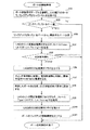
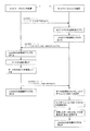
図9は、第1のネットワークスイッチ装置1のアグリゲーション制御部112Aが実行するポート削除処理フローである。
FIG. 9 is a port deletion processing flow executed by the aggregation control unit 112A of the first
アグリゲーション制御部112Aにおいて、削除処理部116Aは、ポート状態管理テーブル113Aを参照して、LAG5に属する第1ポート12の中で、ポート状態が「Link Up」である第1ポート12を抽出する(ステップS31)。そして、削除処理部116Aは、「Link Up」である第1ポート12の数が「1」であるか「2以上」であるかを判断する(ステップS32)。「Link Up」である第1ポート12の数が「1」である場合、削除処理部116Aは、ポートの削除処理を終了する。
In the aggregation control unit 112A, the deletion processing unit 116A refers to the port state management table 113A and extracts the
「Link Up」である第1ポート12の数が「2以上」である場合、削除処理部116Aは、「Link Up」である第1ポート12の中から、リンクダウンさせるポートを選択する、換言すれば、リンクアップ中の第1ポート12の仲から削除する第1ポート12を決定する(ステップS33)。リンクアップから削除する第1ポート12は、例えばリンクアップ中の第1ポート12の中からランダムに選択される。なお、ポート遷移タイマ値が少ない第1ポート12を選択するようにしても良い。ポート遷移タイマ値は、「ポートに割当てられた時間」から「リンクアップ稼動時間」を引いた時間であり、ポートがリンクアップしている時間の残り時間を表す。「ポートに割当てられた時間」は、ポート遷移タイマ値が負の値にならないように、十分に長くされる。また、上位のコンピュータからリンクアップから削除する第1ポート12が指定された場合には、指定された第1ポート12がリンクアップから削除される。
When the number of the
この後、削除処理部116Aは、LAG5のリンクの更新処理を実行中であることを示すフレーム、換言すれば、LA−ECOフレームを第2のネットワークスイッチ装置2のアグリゲーション制御部112Bに送信する(ステップS34)。この時、LA−ECOフレームにおいて、「Link Training」が「1」とされる。このLA−ECOフレームは、リンクダウン開始通知である。 Thereafter, the deletion processing unit 116A transmits a frame indicating that the LAG5 link update processing is being executed, in other words, an LA-ECO frame to the aggregation control unit 112B of the second network switch device 2 ( Step S34). At this time, “Link Training” is set to “1” in the LA-ECO frame. This LA-ECO frame is a link down start notification.
この後、削除処理部116Aは、第2のネットワークスイッチ装置2のアグリゲーション制御部112Bから、送信したLA−ECOフレームに対する応答を待つ(ステップS35)。換言すれば、削除処理部116Aは、送信したLA−ECOフレームにおいて了承を示す「ACK」が「1」とされたフレームの受信を待つ。 Thereafter, the deletion processing unit 116A waits for a response to the transmitted LA-ECO frame from the aggregation control unit 112B of the second network switch device 2 (step S35). In other words, the deletion processing unit 116A waits for reception of a frame in which “ACK” indicating approval is “1” in the transmitted LA-ECO frame.
送信したLA−ECOフレームにおいて却下を示す「NACK」が「1」とされたフレームを受信した場合、又は、何も受信することなくタイムアウトした場合、削除処理部116Aは、処理を終了する。タイムアウトの時間は予め定められる。 When a frame in which “NACK” indicating rejection is “1” is received in the transmitted LA-ECO frame or when a time-out occurs without receiving anything, the deletion processing unit 116A ends the processing. The time-out time is predetermined.
送信したLA−ECOフレームにおいて「ACK」が「1」とされたフレームを受信した場合、削除処理部116Aは、LAG管理テーブル114Aにおいて、LAG5についてのECO処理実行フラグを「0」から「1」に立てる(ステップS36)。 When receiving the frame in which “ACK” is set to “1” in the transmitted LA-ECO frame, the deletion processing unit 116A changes the ECO processing execution flag for LAG5 from “0” to “1” in the LAG management table 114A. (Step S36).
この後、削除処理部116Aは、スイッチ管理部111Aを介して、電源制御部16Aに、リンクアップから削除する第1ポート12のPHYモジュール122への電源供給を切断させる(ステップS37)。換言すれば、削除処理部116Aは、スイッチ管理部111Aに対して電源制御部16Aへの電源供給の切断の依頼を発行し、スイッチ管理部111Aは、受信した電源供給の切断の依頼を電源制御部16Aへ送信し、電源制御部16Aは受信した電源供給の切断を実行する。これにより、リンクアップから削除する第1ポート12のPHYモジュール122への電源供給が切断される。これに応じて、リンクアップから削除する第1ポート12がリンクダウンする。また、削除処理部116Aは、ポート状態管理テーブル113Aにおいて、リンクアップから削除する第1ポート12の状態を、「Link Up」から「ECO auto−poweroff」にする。更に、削除処理部116Aは、リンクアップから削除する第1ポート12のLED123を、ECO状態の表示とする(ステップS38)。
Thereafter, the deletion processing unit 116A causes the power control unit 16A to cut the power supply to the
この後、削除処理部116Aは、LAG5のリンクの更新処理を終了したことを示すフレーム、換言すれば、LA−ECOフレームを第2のネットワークスイッチ装置2のアグリゲーション制御部112Bに送信する(ステップS39)。この時、LA−ECOフレームにおいて、「Link Training」が「0」とされる。このLA−ECOフレームは、リンクダウン終了通知である。更に、削除処理部116Aは、LAG管理テーブル114Aにおいて、LAG5についてのECO処理実行フラグを「1」から「0」に落とす(ステップS310)。 Thereafter, the deletion processing unit 116A transmits a frame indicating that the LAG5 link update processing has been completed, in other words, an LA-ECO frame to the aggregation control unit 112B of the second network switch device 2 (step S39). ). At this time, “Link Training” is set to “0” in the LA-ECO frame. This LA-ECO frame is a link down end notification. Further, the deletion processing unit 116A drops the ECO processing execution flag for LAG5 from “1” to “0” in the LAG management table 114A (step S310).
この後、削除処理部116Aは、ポート状態管理テーブル113Aにおいて、リンクアップから削除する第1ポート12のリンクアップ稼働時間を「0」として(ステップS311)、処理を終了する。
Thereafter, the deletion processing unit 116A sets the link up operation time of the
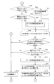
図10は、第2のネットワークスイッチ装置2のアグリゲーション制御部112Bが実行するECOフレーム受信処理フローである。
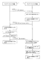
FIG. 10 is an ECO frame reception process flow executed by the aggregation control unit 112B of the second
第2のネットワークスイッチ装置2のアグリゲーション制御部112Bにおいて、LAG監視部115Bは、第1のネットワークスイッチ装置1のアグリゲーション制御部112AからLA−ECOフレームを受信すると、受信したLA−ECOフレームにより指定されたLAG5をサーチする(ステップS41)。換言すれば、ステップS41において、LAG監視部115Bは、受信したLA−ECOフレームにより指定されたLAG5が存在するか否かを判断する。
In the aggregation control unit 112B of the second
受信したLA−ECOフレームにより指定されたLAG5が存在しない場合、LAG監視部115Bは、処理を終了する。 When there is no LAG5 specified by the received LA-ECO frame, the LAG monitoring unit 115B ends the process.
受信したLA−ECOフレームにより指定されたLAG5が存在する場合、LAG監視部115Bは、該当するLAG5について、実行中のリンクの更新処理があるか否かを判断する(ステップS42)。
When the
受信したLA−ECOフレームにより指定されたLAG5について、実行中のリンクの更新処理がない場合、LAG監視部115Bは、受信したLA−ECOフレームの「Link Training」が「1」であるか「0」であるかを判断する(ステップS43)。
When there is no link update process in progress for the
「Link Training」が「1」である場合、LAG監視部115Bは、受信したLA−ECOフレームの「ACK」が「1」であるか「0」であるかを判断する(ステップS44)。「ACK」が「0」である場合、LAG監視部115Bは、リンクの更新処理を実行する更新処理部118Bを起動して(ステップS45)、その後、処理を終了する。リンクの更新処理については、図11を参照して後述する。「ACK」が「1」である場合、LAG監視部115Bは、処理を終了する。 When “Link Training” is “1”, the LAG monitoring unit 115B determines whether “ACK” of the received LA-ECO frame is “1” or “0” (step S44). When “ACK” is “0”, the LAG monitoring unit 115B activates the update processing unit 118B that executes link update processing (step S45), and then ends the processing. The link update process will be described later with reference to FIG. When “ACK” is “1”, the LAG monitoring unit 115B ends the process.
ステップS43において、「Link Training」が「0」である場合、LAG監視部115Bは、受信したLA−ECOフレームの「ECO mode」を参照して、「ECO mode」の値をLAG管理テーブル114Bの「Partner ECO処理モード」に記録して(ステップS46)、処理を終了する。 In step S43, when “Link Training” is “0”, the LAG monitoring unit 115B refers to the “ECO mode” of the received LA-ECO frame, and sets the value of “ECO mode” in the LAG management table 114B. Recording is performed in “Partner ECO processing mode” (step S46), and the processing is terminated.
ステップS42において、受信したLA−ECOフレームにより指定されたLAG5について、実行中のリンクの更新処理がある場合、LAG監視部115Bは、受信したLA−ECOフレームの「Link Training」が「1」であるか「0」であるかを判断する(ステップS47)。
In step S42, when there is a link update process in progress for the
「Link Training」が「1」である場合、LAG監視部115Bは、処理を終了する。「Link Training」が「0」である場合、LAG監視部115Bは、受信したLA−ECOフレームの「ACK」が「1」であるか「0」であるかを判断する(ステップS48)。「ACK」が「1」である場合、LAG監視部115Bは、処理を終了する。「ACK」が「0」である場合、LAG監視部115Bは、実行中のリンクの更新処理を実行中の更新処理部118Bに対して、「Link Training」が「0」であるLA−ECOフレームを受信したことを通知して(ステップS49)、処理を終了する。 When “Link Training” is “1”, the LAG monitoring unit 115B ends the process. When “Link Training” is “0”, the LAG monitoring unit 115B determines whether “ACK” of the received LA-ECO frame is “1” or “0” (step S48). When “ACK” is “1”, the LAG monitoring unit 115B ends the process. When “ACK” is “0”, the LAG monitoring unit 115B sends an LA-ECO frame whose “Link Training” is “0” to the update processing unit 118B that is executing the update process of the link being executed. Is received (step S49), and the process is terminated.
図11は、第2のネットワークスイッチ装置2のアグリゲーション制御部112Bが実行するリンク更新処理フローである。
FIG. 11 is a link update processing flow executed by the aggregation control unit 112B of the second
アグリゲーション制御部112Bにおいて、更新処理部118Bは、スイッチ管理部111Bを介して、全ての第2ポート22のPHYモジュールへ電源制御部16Bから電源を供給させる(ステップS51)。換言すれば、更新処理部118Bは、スイッチ管理部111Bに対して電源制御部16Bへの電源供給の依頼を発行し、スイッチ管理部111Bは、受信した電源供給の依頼を電源制御部16Bへ送信し、電源制御部16Bは受信した電源供給を実行する。これにより、全ての第1ポート22のPHYモジュールへ電源が供給される。
In the aggregation control unit 112B, the update processing unit 118B supplies power from the power control unit 16B to the PHY modules of all the
この後、更新処理部118Bは、ポート状態管理テーブル113Bを参照して、状態が「ECO auto−poweroff」である第2ポート22のLEDを、「Link Down」の表示に変更する(ステップS52)。更に、更新処理部118Bは、状態が「ECO auto−poweroff」である第2ポート22の状態を、ポート状態管理テーブル113Bにおいて、「Link state unknown」に変更する(ステップS53)。
Thereafter, the update processing unit 118B refers to the port state management table 113B, and changes the LED of the
この後、更新処理部118Bは、LAG管理テーブル114Bにおいて、LAG5についてのECO処理実行フラグを「0」から「1」に立てる(ステップS54)。 Thereafter, the update processing unit 118B sets the ECO processing execution flag for LAG5 from “0” to “1” in the LAG management table 114B (step S54).
この後、更新処理部118Bは、LAG5のリンクの更新処理の実行を了解することを示すフレームを第1のネットワークスイッチ装置1のアグリゲーション制御部112Aに送信する(ステップS55)。LAG5のリンクの更新処理の実行を了解することを示すフレームは、受信したLA−ECOフレームにおいて「ACK」が「1」とされたフレームである。 Thereafter, the update processing unit 118B transmits a frame indicating that the execution of the link update process of the LAG5 is accepted to the aggregation control unit 112A of the first network switch device 1 (step S55). The frame indicating that the execution of the LAG5 link update process is accepted is a frame in which “ACK” is set to “1” in the received LA-ECO frame.
この後、更新処理部118Bは、第1のネットワークスイッチ装置1のアグリゲーション制御部112Aから「Link Training」が「0」とされたLA−ECOフレームを受信するのを待つ(ステップS56)。なお、実際には、前述したように、「Link Training」が「0」とされたLA−ECOフレームは、ステップS49において検出される。 Thereafter, the update processing unit 118B waits to receive an LA-ECO frame in which “Link Training” is set to “0” from the aggregation control unit 112A of the first network switch device 1 (step S56). Actually, as described above, the LA-ECO frame in which “Link Training” is set to “0” is detected in step S49.
なお、何も受信することなくタイムアウトした場合、更新処理部118Bは、処理を終了する。タイムアウトの時間は予め定められる。 Note that if a timeout occurs without receiving anything, the update processing unit 118B ends the process. The time-out time is predetermined.
「Link Training」が「0」とされたLA−ECOフレームを受信した場合、更新処理部118Bは、LAG5に属する第2ポート22の状態を確認することにより、リンクダウンしているリンクを抽出する(ステップS57)。
When the LA-ECO frame having “Link Training” set to “0” is received, the update processing unit 118B extracts the link that is linked down by checking the state of the
この後、更新処理部118Bは、ポート状態管理テーブル113Bにおいて、リンクダウンしている第2ポート22の状態を、「ECO auto−poweroff」に変更する(ステップS58)。
Thereafter, the update processing unit 118B changes the state of the
更に、更新処理部118Bは、スイッチ管理部111Bを介して、リンクダウンしている第2ポート22のPHYモジュールへの電源制御部16Bからの電源供給を切断させる(ステップS59)。換言すれば、更新処理部118Bは、スイッチ管理部111Bに対して電源制御部16Bへの電源供給の切断の依頼を発行し、スイッチ管理部111Bは、受信した電源供給の切断の依頼を電源制御部16Bへ送信し、電源制御部16Bは受信した電源供給の切断を実行する。これにより、リンクダウンしている第2ポート22のPHYモジュールへの電源供給が切断される。
Further, the update processing unit 118B disconnects the power supply from the power control unit 16B to the PHY module of the
この後、更新処理部118Bは、リンクダウンしている第2ポート22のLED、換言すれば、リンクアップから削除された第2ポート22のLEDを、ECO状態の表示とする(ステップS510)。更に、更新処理部118Bは、LAG管理テーブル114Bにおいて、LAG5についてのECO処理実行フラグを「1」から「0」に落とす(ステップS511)。そして、更新処理部118Bは、ポート状態管理テーブル113Bにおいて、リンクダウンしている第2ポート22のリンクアップ稼働時間を「0」として(ステップS512)、処理を終了する。
Thereafter, the update processing unit 118B displays the LED of the
図12は、リンク削除処理の説明図である。 FIG. 12 is an explanatory diagram of the link deletion process.
第1のネットワークスイッチ装置1は、リンクダウン処理に先立って、第2のネットワークスイッチ装置2にLA−ECOフレームを送信する。この時、LA−ECOフレームにおいて、「Link Training」が「1」とされる。「Link Training」が「1」であり、「ACK」が「0」であるので、このLA−ECOフレームは、リンクダウン開始通知である。
The first
第2のネットワークスイッチ装置2が、リンクダウン開始通知としてのLA−ECOフレームを受信した場合、これに応じて、複数の第2ポート22の電源を投入し、LAG5についてのECO処理実行フラグを立てる。
When the second
この後、第2のネットワークスイッチ装置2が、第1のネットワークスイッチ装置1にLA−ECOフレームを送信する。この時、LA−ECOフレームにおいて、「Link Training」が「1」とされ、「ACK」が「1」とされる。「Link Training」が「1」であり、「ACK」が「1」であるので、このLA−ECOフレームは、リンクダウン開始通知に対する応答である。
Thereafter, the second
第1のネットワークスイッチ装置1は、リンクダウン開始通知に対する応答としてのLA−ECOフレームを受信した場合、これに応じて、リンクダウン処理を実行する。
When the first
具体的には、第1のネットワークスイッチ装置1は、LAG5についてのECO処理実行フラグを立てる。その後、第1のネットワークスイッチ装置1は、LAG5の使用帯域情報に基づいて、LAG5に属する複数の第1ポート12の中で、少なくとも1個の第1ポート12の電源供給を切断する。これにより、第1のネットワークスイッチ装置1は、少なくとも1個の第1ポート12をリンクダウンする。
Specifically, the first
更に、第1のネットワークスイッチ装置1は、使用帯域情報に基づいて電源供給を切断された少なくとも1個の第1ポート12を、リンクダウンを示すエラー通知の対象から除外する。これに応じて、第1のネットワークスイッチ装置1は、使用帯域情報に基づいて電源供給を切断された少なくとも1個の第1ポート12のLED123を、ECO状態の表示とする。
Furthermore, the first
このリンクダウン処理の後に、第1のネットワークスイッチ装置1は、第2のネットワークスイッチ装置2にLA−ECOフレームを送信する。この時、LA−ECOフレームにおいて、「Link Training」が「0」とされる。「Link Training」が「0」であり、「ACK」が「0」であるので、このLA−ECOフレームは、リンクダウン終了通知である。
After the link-down process, the first
この後、第1のネットワークスイッチ装置1は、LAG5についてのECO処理実行フラグを落とす。
Thereafter, the first
第2のネットワークスイッチ装置2は、リンクダウン終了通知を受信した場合、これに応じて、LAG5に属する複数の第2ポート22の状態をチェックして、リンクダウンしている少なくとも1個の第2ポート22を抽出する。そして、第2のネットワークスイッチ装置2は、複数の第2ポート22の中で、第1ポート12のリンクダウンに応じてリンクダウンしている少なくとも1個の第2ポート22の電源供給を切断する。これにより、リンクダウンしているリンクの両端のポートの電源供給が切断される。
When the second
更に、第2のネットワークスイッチ装置2は、第1ポート12のリンクダウンに応じたリンクダウンに基づいて電源供給を切断された少なくとも1個の第2ポート22を、リンクダウンを示すエラー通知の対象から除外する。これに応じて、第2のネットワークスイッチ装置2は、第1ポート12のリンクダウンに応じたリンクダウンに基づいて電源供給を切断された少なくとも1個の第2ポート22のLEDを、ECO状態の表示とする。
Furthermore, the second
この後、第2のネットワークスイッチ装置2は、LAG5についてのECO処理実行フラグを落とす。
Thereafter, the second
図13は、リンク追加処理の説明図である。 FIG. 13 is an explanatory diagram of the link addition process.
第1のネットワークスイッチ装置1は、リンクアップ処理に先立って、第2のネットワークスイッチ装置2にLA−ECOフレームを送信する。この時、LA−ECOフレームにおいて、「Link Training」が「1」とされる。「Link Training」が「1」であり、「ACK」が「0」であるので、このLA−ECOフレームは、リンクアップ開始通知である。
The first
第2のネットワークスイッチ装置2が、リンクアップ開始通知としてのLA−ECOフレームを受信した場合、これに応じて、複数の第2ポート22の電源を投入し、LAG5についてのECO処理実行フラグを「0」から「1」に立てる。
When the second
この後、第2のネットワークスイッチ装置2が、第1のネットワークスイッチ装置1にLA−ECOフレームを送信する。この時、LA−ECOフレームにおいて、「Link Training」が「1」とされ、「ACK」が「1」とされる。「Link Training」が「1」で「ACK」が「1」であるので、このLA−ECOフレームは、リンクアップ開始通知に対する応答である。
Thereafter, the second
第1のネットワークスイッチ装置1は、リンクアップ開始通知に対する応答としてのLA−ECOフレームを受信した場合、これに応じて、リンクアップ処理を実行する。
When the first
具体的には、第1のネットワークスイッチ装置1は、LAG5についてのECO処理実行フラグを立てる。その後、第1のネットワークスイッチ装置1は、LAG5の使用帯域情報に基づいて、LAG5に属する複数の第1ポート12の中で、少なくとも1個の第1ポート12の電源を供給する。これにより、第1のネットワークスイッチ装置1は、前記少なくとも1個の第1ポート12をリンクアップする。
Specifically, the first
更に、第1のネットワークスイッチ装置1は、使用帯域情報に基づいて電源を供給された少なくとも1個の第1ポート12を、リンクダウンを示すエラー通知の対象とする。これに応じて、第1のネットワークスイッチ装置1は、使用帯域情報に基づいて電源を供給された少なくとも1個の第1ポート12のLED123を、ECO状態の表示からリンクアップの表示とする。
Further, the first
このリンクアップ処理の後に、第1のネットワークスイッチ装置1は、第2のネットワークスイッチ装置2にLA−ECOフレームを送信する。この時、LA−ECOフレームにおいて、「Link Training」が「0」とされる。「Link Training」が「0」であり、「ACK」が「0」であるので、このLA−ECOフレームは、リンクアップ終了通知である。
After this link-up process, the first
この後、第1のネットワークスイッチ装置1は、LAG5についてのECO処理実行フラグを「1」から「0」に落とす。
Thereafter, the first
第2のネットワークスイッチ装置2は、リンクアップ終了通知を受信した場合、これに応じて、LAG5に属する複数の第2ポート22の状態をチェックして、リンクダウンしている第2ポート22を抽出する。そして、第2のネットワークスイッチ装置2は、複数の第2ポート22の中で、第1ポート12のリンクダウンに応じてリンクダウンしている第2ポート22の電源供給を切断する。これにより、新たにリンクアップしたポートを含むリンクアップしているポートを除いて、リンクダウンしているリンクの両端のポートの電源供給が切断される。
When the second
更に、第2のネットワークスイッチ装置2は、第1ポート12のリンクダウンに応じたリンクダウンに基づいて電源供給を切断された第2ポート22を、リンクダウンを示すエラー通知の対象から除外する。これに応じて、第2のネットワークスイッチ装置2は、第1ポート12のリンクダウンに応じたリンクダウンに基づいて電源供給を切断された第2ポート22のLEDを、ECO状態の表示とする。
Further, the second
この後、第2のネットワークスイッチ装置2は、LAG5についてのECO処理実行フラグを「1」から「0」に落とす。
Thereafter, the second
1 第1のネットワークスイッチ装置
2 第2のネットワークスイッチ装置
3、4 リンク
5 リンクアグリゲーショングループ(LAG)
11、21 リンクアグリゲーション制御部
12 第1ポート
13 データスイッチング部
14 アグリゲータ部
15 送受信制御部
16 電源制御部
17 監視部
18 第3ポート
22 第2ポート
28 第4ポート
111 スイッチ管理部
112 アグリゲーション制御部
121 MAC部
122 PHYモジュール
123 LED
113 ポート状態管理テーブル
114 LAG管理テーブル
115 LAG監視部
116 削除処理部
117 追加処理部
118 更新処理部DESCRIPTION OF
DESCRIPTION OF
113 Port Status Management Table 114 LAG Management Table 115
Claims (10)
前記第1の通信装置が、前記リンクアグリゲーショングループの使用帯域情報に基づいて、前記複数の第1ポートの中の少なくとも1個の第1ポートの物理層モジュールに対する電源供給を切断し前記少なくとも1個の第1ポートをリンクダウンするステップと、
前記第1の通信装置が、前記リンクダウンするステップの後に、前記第2の通信装置にリンクダウン終了通知を送信するステップと、
前記リンクダウン終了通知を受信した前記第2の通信装置が、前記複数の第2ポートの中のリンクダウンしている少なくとも1個の第2ポートの物理層モジュールに対する電源供給を切断するステップとを含む
ことを特徴とする通信システムの制御方法。 Using a plurality of links connecting a plurality of first ports of the first communication device and a plurality of second ports of the second communication device as a link aggregation group that is a virtual one link, A control method of a communication system for performing communication between a first communication device and the second communication device,
The first communication device cuts off the power supply to the physical layer module of at least one first port of the plurality of first ports based on the bandwidth usage information of the link aggregation group, and the at least one Linking down the first port of
The first communication device transmitting a link down end notification to the second communication device after the link down step;
The second communication device that has received the link down end notification cuts off power supply to the physical layer module of at least one second port that is linked down among the plurality of second ports. A control method for a communication system, comprising:
前記第2の通信装置が、前記使用帯域情報に基づいて電源供給を切断された前記少なくとも1個の第1ポートのリンクダウンに応じてリンクダウンした前記少なくとも1個の第2ポートを、リンクダウンを示すエラー通知の対象から除外する
ことを特徴とする請求項1に記載の通信システムの制御方法。 The first communication device excludes the at least one first port whose power supply is cut off based on the use band information from an error notification target indicating a link down;
The second communication device links down the at least one second port linked down in response to a link down of the at least one first port whose power supply is cut off based on the use band information. 2. The communication system control method according to claim 1, wherein the error notification target is excluded from an error notification target.
前記第1の通信装置が、前記リンクダウンするステップに先立って、前記第2の通信装置にリンクダウン開始通知を送信するステップと、
前記リンクダウン開始通知を受信した前記第2の通信装置が、前記複数の第2ポートの電源を投入し、前記リンクダウン開始通知に対する応答を前記第1の通信装置に返信するステップとを含む
ことを特徴とする請求項1に記載の通信システムの制御方法。 The communication system control method further comprises:
The first communication device transmits a link down start notification to the second communication device prior to the link down step;
Receiving the link down start notification, turning on the power of the plurality of second ports and returning a response to the link down start notification to the first communication device. The method of controlling a communication system according to claim 1.
前記第1の通信装置が、前記通信システムのグループの使用帯域情報に基づいて、前記複数の第1ポートの中の少なくとも1個の第1ポートの電源を投入し前記少なくとも1個の第1ポートをリンクアップするステップと、
前記第1の通信装置が、前記リンクアップするステップの後に、前記第2の通信装置にリンクアップ終了通知を送信するステップと、
前記リンクアップ終了通知を受信した前記第2の通信装置が、前記複数の第2ポートの中のリンクダウンしている第2ポートの電源供給を切断するステップとを含む
ことを特徴とする請求項1に記載の通信システムの制御方法。 The communication system control method further comprises:
The first communication device turns on the power of at least one first port of the plurality of first ports based on the use band information of the group of the communication systems, and the at least one first port The steps of linking up
The first communication device transmitting a link-up end notification to the second communication device after the link-up step; and
The second communication device that has received the link-up end notification cuts off the power supply to the second port that is linked down among the plurality of second ports. The control method of the communication system of Claim 1.
前記第1の通信装置が、前記リンクアップするステップに先立って、前記第2の通信装置にリンクアップ開始通知を送信するステップと、
前記リンクアップ開始通知を受信した前記第2の通信装置が、前記複数の第2ポートの電源を投入し、前記リンクアップ開始通知に対する応答を前記第1の通信装置に返信するステップとを含む
ことを特徴とする請求項4に記載の通信システムの制御方法。 The communication system control method further comprises:
The first communication device transmitting a link-up start notification to the second communication device prior to the link-up step;
The second communication device receiving the link-up start notification turns on the power of the plurality of second ports and returns a response to the link-up start notification to the first communication device. The control method of the communication system according to claim 4.
前記第1の通信装置が、前記通信システムのグループの使用帯域情報に基づいて必要なリンクの数を算出し、前記必要なリンクの数と現在リンクアップしているリンクの数とを比較するステップを含み、
前記第1の通信装置が、前記比較に基づいて、前記必要なリンクの数が現在リンクアップしているリンクの数より少ない場合に前記リンクダウンするステップを実行し、前記必要なリンクの数が現在リンクアップしているリンクの数より多い場合に前記リンクアップするステップを実行する
ことを特徴とする請求項4に記載の通信システムの制御方法。 The communication system control method further comprises:
The first communication device calculates the number of necessary links based on the used bandwidth information of the group of the communication system, and compares the number of necessary links with the number of links that are currently linked up. Including
The first telecommunication device performs the link down step based on the comparison if the number of required links is less than the number of links that are currently linked up; The communication system control method according to claim 4, wherein the link-up step is executed when the number of links that are currently linked up is larger than the number of links.
前記第1の通信装置が、前記通信システムのグループの使用帯域情報に基づいて、現在リンクアップしているリンクについて、前記リンクアップしている時間が予め定められた閾値を超えているかを判断するステップを含み、
前記第1の通信装置が、前記リンクアップしている時間が前記閾値を超えているリンクが存在する場合に、前記リンクアップするステップを実行した後に、前記リンクアップしている時間が前記閾値を超えているリンクについて、前記リンクダウンするステップを実行する
ことを特徴とする請求項1に記載の通信システムの制御方法。 The communication system control method further comprises:
The first communication apparatus determines whether the link up time exceeds a predetermined threshold for a link that is currently linked up based on the use band information of the group of the communication system. Including steps,
When there is a link in which the first communication apparatus has exceeded the threshold for the link up time, the link up time is set to the threshold after executing the link up step. The communication system control method according to claim 1, wherein the link down step is executed for a link exceeding the link.
前記リンクアグリゲーショングループの使用帯域情報に基づいて、前記複数の第1ポートの中の少なくとも1個の第1ポートの物理層モジュールに対する電源供給を切断し前記少なくとも1個の第1ポートをリンクダウンし、前記第2の通信装置にリンクダウン終了通知を送信する第1の通信装置と、
前記リンクダウン終了通知を受信した前記第2の通信装置が、前記複数の第2ポートの中のリンクダウンしている少なくとも1個の第2ポートの物理層モジュールに対する電源供給を切断する第2の通信装置とを含む
ことを特徴とする通信システム。 Using a plurality of links connecting a plurality of first ports of the first communication device and a plurality of second ports of the second communication device as a link aggregation group that is a virtual one link, A communication system for performing communication between a first communication device and the second communication device,
Based on the bandwidth usage information of the link aggregation group, the power supply to the physical layer module of at least one first port of the plurality of first ports is disconnected, and the at least one first port is linked down. A first communication device that transmits a link down end notification to the second communication device;
The second communication device that has received the link down end notification disconnects power supply to the physical layer module of at least one second port that is linked down among the plurality of second ports. A communication system comprising: a communication device.
前記複数のリンクを介して、他の通信装置の複数の第2のポートと接続される複数の第1のポートと、
前記リンクアグリゲーショングループの使用帯域情報に基づいて、前記複数の第1のポートの中の少なくとも1個の第1のポートの物理層モジュールに対する電源供給を切断し前記少なくとも1個の第1のポートをリンクダウンし、前記他の通信装置にリンクダウン終了通知を送信するリンクアグリゲーション制御部とを含む
ことを特徴とする通信装置。 A communication device that communicates with other communication devices using a plurality of links as a link aggregation group that is a single virtual link,
A plurality of first ports connected to a plurality of second ports of other communication devices via the plurality of links;
Based on the bandwidth usage information of the link aggregation group, the power supply to the physical layer module of at least one first port of the plurality of first ports is disconnected, and the at least one first port is A link aggregation control unit configured to link down and transmit a link down end notification to the other communication device.
前記複数のリンクを介して、他の通信装置の複数の第1のポートと接続される複数の第2のポートと、
前記他の通信装置から、前記リンクアグリゲーショングループの使用帯域情報に基づいて前記複数の第1のポートの中の少なくとも1個の第1のポートの物理層モジュールに対する電源供給を切断し前記少なくとも1個の第1のポートをリンクダウンしたことを示す、リンクダウン終了通知を受信し、前記複数の第2ポートの中のリンクダウンしている少なくとも1個の第2ポートの物理層モジュールに対する電源供給を切断するリンクアグリゲーション制御部とを含む
ことを特徴とする通信装置。 A communication device that communicates with other communication devices using a plurality of links as a link aggregation group that is a single virtual link,
A plurality of second ports connected to a plurality of first ports of other communication devices via the plurality of links;
The power supply to the physical layer module of at least one first port of the plurality of first ports is disconnected from the other communication device based on the use band information of the link aggregation group, and the at least one Receiving a link down end notification indicating that the first port of the second port is linked down, and supplying power to the physical layer module of at least one second port of the plurality of second ports that is linked down A communication apparatus comprising: a link aggregation control unit that disconnects.
Applications Claiming Priority (1)
| Application Number | Priority Date | Filing Date | Title |
|---|---|---|---|
| PCT/JP2010/070331 WO2012066625A1 (en) | 2010-11-16 | 2010-11-16 | Method of controlling communication system, communication system, communication device |
Publications (2)
| Publication Number | Publication Date |
|---|---|
| JPWO2012066625A1 JPWO2012066625A1 (en) | 2014-05-12 |
| JP5534026B2 true JP5534026B2 (en) | 2014-06-25 |
Family
ID=46083591
Family Applications (1)
| Application Number | Title | Priority Date | Filing Date |
|---|---|---|---|
| JP2012544024A Expired - Fee Related JP5534026B2 (en) | 2010-11-16 | 2010-11-16 | Communication system control method, communication system, and communication apparatus |
Country Status (4)
| Country | Link |
|---|---|
| US (1) | US20130250829A1 (en) |
| EP (1) | EP2642699A1 (en) |
| JP (1) | JP5534026B2 (en) |
| WO (1) | WO2012066625A1 (en) |
Families Citing this family (16)
| Publication number | Priority date | Publication date | Assignee | Title |
|---|---|---|---|---|
| CN102364892B (en) * | 2011-10-12 | 2013-04-24 | 华为技术有限公司 | Link aggregation control protocol (LACP) link switching and data transmission method and apparatus thereof |
| US9608899B2 (en) * | 2011-11-21 | 2017-03-28 | Qualcomm Incorporated | Packet-based aggregation of data streams across disparate networking interfaces |
| CN102769568B (en) * | 2012-07-19 | 2015-10-21 | 中兴通讯股份有限公司 | A kind of flow forwarding method based on virtual switch cluster and system |
| CN102916899B (en) * | 2012-09-28 | 2016-08-03 | 华为技术有限公司 | Power-economizing method under a kind of Trunk networking and device |
| WO2015141467A1 (en) * | 2014-03-17 | 2015-09-24 | 日本電気株式会社 | Receiving device, number of lines recognition circuit, number of lines recognition method and program |
| CN104283724B (en) * | 2014-10-31 | 2017-10-27 | 大唐移动通信设备有限公司 | A kind of management method and equipment of aggregation group state |
| US9548892B2 (en) * | 2015-01-26 | 2017-01-17 | Arista Networks, Inc. | Method and system for preventing polarization in a network |
| US10171306B2 (en) * | 2015-02-26 | 2019-01-01 | Cisco Technology, Inc. | Automatic discovery and provisioning of multi-chassis etherchannel peers |
| US10425319B2 (en) | 2015-05-21 | 2019-09-24 | Huawei Technologies Co., Ltd. | Transport software defined networking (SDN)—zero configuration adjacency via packet snooping |
| US10015053B2 (en) * | 2015-05-21 | 2018-07-03 | Huawei Technologies Co., Ltd. | Transport software defined networking (SDN)—logical link aggregation (LAG) member signaling |
| US10565041B2 (en) | 2017-05-19 | 2020-02-18 | Western Digital Technologies, Inc. | Managing phys of a data storage target device |
| JP7020070B2 (en) * | 2017-11-16 | 2022-02-16 | 富士通株式会社 | Relay device and program |
| US11088963B2 (en) * | 2019-12-16 | 2021-08-10 | Dell Products L.P. | Automatic aggregated networking device backup link configuration system |
| US11652753B2 (en) * | 2020-07-29 | 2023-05-16 | Hewlett Packard Enterprise Development Lp | Link aggregation group optimization |
| CN112260901B (en) * | 2020-10-23 | 2022-05-03 | 北京信而泰科技股份有限公司 | Network damage instrument and use method thereof |
| CN112468393B (en) * | 2020-11-04 | 2022-09-09 | 烽火通信科技股份有限公司 | Method and device for selecting forwarding port based on link EEE and power consumption and electronic equipment |
Family Cites Families (10)
| Publication number | Priority date | Publication date | Assignee | Title |
|---|---|---|---|---|
| US7327748B2 (en) * | 2002-01-28 | 2008-02-05 | Alcatel Lucent | Enterprise switching device and method |
| JP4155105B2 (en) | 2003-05-20 | 2008-09-24 | 日本電気株式会社 | Link aggregation redundancy method, system, program, and network relay device |
| JP2006005437A (en) * | 2004-06-15 | 2006-01-05 | Fujitsu Ltd | Traffic distributed control unit |
| EP1942608A4 (en) * | 2005-09-02 | 2011-01-12 | Fujitsu Ltd | Network interface control program and network interface controller |
| US7729361B2 (en) * | 2006-02-24 | 2010-06-01 | Cisco Technology, Inc. | Method and system for power-efficient adaptive link aggregation |
| JP2008252282A (en) | 2007-03-29 | 2008-10-16 | Kyocera Corp | Radio base station apparatus |
| US7813341B2 (en) * | 2008-01-29 | 2010-10-12 | International Business Machines Corporation | Overhead reduction for multi-link networking environments |
| JP5513342B2 (en) * | 2010-02-26 | 2014-06-04 | アラクサラネットワークス株式会社 | Packet relay device |
| JPWO2011108378A1 (en) * | 2010-03-01 | 2013-06-24 | 日本電気株式会社 | Transmission apparatus, transmission method and transmission system |
| US20130003549A1 (en) * | 2011-06-30 | 2013-01-03 | Broadcom Corporation | Resilient Hashing for Load Balancing of Traffic Flows |
-
2010
- 2010-11-16 EP EP10859681.8A patent/EP2642699A1/en not_active Withdrawn
- 2010-11-16 JP JP2012544024A patent/JP5534026B2/en not_active Expired - Fee Related
- 2010-11-16 WO PCT/JP2010/070331 patent/WO2012066625A1/en active Application Filing
-
2013
- 2013-05-13 US US13/892,343 patent/US20130250829A1/en not_active Abandoned
Non-Patent Citations (2)
| Title |
|---|
| CSNG200800485053; 河野義幸,福田豊,田村瞳,川原憲治,尾家祐二: '動的な物理リンク数制御によるスイッチ省電力化手法の提案' 電子情報通信学会技術研究報告 Vol.107 No.525 IN2007-216, 20080228, p343-348, 社団法人電子情報通信学会 * |
| JPN6010073153; 河野義幸,福田豊,田村瞳,川原憲治,尾家祐二: '動的な物理リンク数制御によるスイッチ省電力化手法の提案' 電子情報通信学会技術研究報告 Vol.107 No.525 IN2007-216, 20080228, p343-348, 社団法人電子情報通信学会 * |
Also Published As
| Publication number | Publication date |
|---|---|
| EP2642699A1 (en) | 2013-09-25 |
| JPWO2012066625A1 (en) | 2014-05-12 |
| US20130250829A1 (en) | 2013-09-26 |
| WO2012066625A1 (en) | 2012-05-24 |
Similar Documents
| Publication | Publication Date | Title |
|---|---|---|
| JP5534026B2 (en) | Communication system control method, communication system, and communication apparatus | |
| US8971337B2 (en) | Packet relay device | |
| KR102114243B1 (en) | Network, master, hub, and method for providing a bluetooth infrastructure | |
| CN102055525B (en) | loop detection and control method | |
| US8098682B2 (en) | System and method for interfacing with a management system | |
| US8400912B2 (en) | Activating a tunnel upon receiving a control packet | |
| US7719956B2 (en) | Trunk network system for multipoint-to-multipoint relay | |
| CN104301146A (en) | Link switching method and device in software defined network | |
| US9385944B2 (en) | Communication system, path switching method and communication device | |
| CN103209099B (en) | A kind of automatic switching protection method of internodal network communication circuit | |
| CN102724030A (en) | Stacking system with high reliability | |
| CN101860492A (en) | Quick switching method, device and system | |
| CN111654435B (en) | Link protection fault processing system and method based on LACP | |
| JP2012522455A (en) | Energy efficient Ethernet network nodes and methods of using Ethernet network nodes | |
| CN103595626A (en) | Method for achieving dynamic path planning in ring network | |
| CN105340230A (en) | Virtual chassis topology management | |
| CN103227725A (en) | Method and device for dual-server backup of firewall | |
| US8279752B1 (en) | Activating tunnels using control packets | |
| JP5974911B2 (en) | Communication system and network relay device | |
| CN106936510B (en) | Method for adjusting optical power, network equipment and network management equipment | |
| CN101340377B (en) | Method, apparatus and system for data transmission in double layer network | |
| CN104639358A (en) | Batched network port switching method and system | |
| US7860090B2 (en) | Method for processing LMP packets, LMP packet processing unit and LMP packet processing node | |
| CN102064956A (en) | Method for regulating aging time, system and modulator-demodulator | |
| CN103001832B (en) | The detection method of distributed file system interior joint and device |
Legal Events
| Date | Code | Title | Description |
|---|---|---|---|
| TRDD | Decision of grant or rejection written | ||
| A01 | Written decision to grant a patent or to grant a registration (utility model) |
Free format text: JAPANESE INTERMEDIATE CODE: A01 Effective date: 20140401 |
|
| R150 | Certificate of patent or registration of utility model |
Ref document number: 5534026 Country of ref document: JP Free format text: JAPANESE INTERMEDIATE CODE: R150 |
|
| A61 | First payment of annual fees (during grant procedure) |
Free format text: JAPANESE INTERMEDIATE CODE: A61 Effective date: 20140414 |
|
| LAPS | Cancellation because of no payment of annual fees |