JP5525532B2 - Cardiac function management incorporating myocardial contractility adjustment - Google Patents
Cardiac function management incorporating myocardial contractility adjustment Download PDFInfo
- Publication number
- JP5525532B2 JP5525532B2 JP2011527815A JP2011527815A JP5525532B2 JP 5525532 B2 JP5525532 B2 JP 5525532B2 JP 2011527815 A JP2011527815 A JP 2011527815A JP 2011527815 A JP2011527815 A JP 2011527815A JP 5525532 B2 JP5525532 B2 JP 5525532B2
- Authority
- JP
- Japan
- Prior art keywords
- ccm
- therapy
- circuit
- adverse event
- neural stimulation
- Prior art date
- Legal status (The legal status is an assumption and is not a legal conclusion. Google has not performed a legal analysis and makes no representation as to the accuracy of the status listed.)
- Expired - Fee Related
Links
Images


Classifications
-
- A—HUMAN NECESSITIES
- A61—MEDICAL OR VETERINARY SCIENCE; HYGIENE
- A61N—ELECTROTHERAPY; MAGNETOTHERAPY; RADIATION THERAPY; ULTRASOUND THERAPY
- A61N1/00—Electrotherapy; Circuits therefor
- A61N1/18—Applying electric currents by contact electrodes
- A61N1/32—Applying electric currents by contact electrodes alternating or intermittent currents
- A61N1/36—Applying electric currents by contact electrodes alternating or intermittent currents for stimulation
- A61N1/362—Heart stimulators
- A61N1/3627—Heart stimulators for treating a mechanical deficiency of the heart, e.g. congestive heart failure or cardiomyopathy
-
- A—HUMAN NECESSITIES
- A61—MEDICAL OR VETERINARY SCIENCE; HYGIENE
- A61N—ELECTROTHERAPY; MAGNETOTHERAPY; RADIATION THERAPY; ULTRASOUND THERAPY
- A61N1/00—Electrotherapy; Circuits therefor
- A61N1/18—Applying electric currents by contact electrodes
- A61N1/32—Applying electric currents by contact electrodes alternating or intermittent currents
- A61N1/36—Applying electric currents by contact electrodes alternating or intermittent currents for stimulation
- A61N1/3605—Implantable neurostimulators for stimulating central or peripheral nerve system
- A61N1/36128—Control systems
- A61N1/36146—Control systems specified by the stimulation parameters
- A61N1/36182—Direction of the electrical field, e.g. with sleeve around stimulating electrode
- A61N1/36185—Selection of the electrode configuration
-
- A—HUMAN NECESSITIES
- A61—MEDICAL OR VETERINARY SCIENCE; HYGIENE
- A61N—ELECTROTHERAPY; MAGNETOTHERAPY; RADIATION THERAPY; ULTRASOUND THERAPY
- A61N1/00—Electrotherapy; Circuits therefor
- A61N1/18—Applying electric currents by contact electrodes
- A61N1/32—Applying electric currents by contact electrodes alternating or intermittent currents
- A61N1/36—Applying electric currents by contact electrodes alternating or intermittent currents for stimulation
- A61N1/362—Heart stimulators
- A61N1/365—Heart stimulators controlled by a physiological parameter, e.g. heart potential
- A61N1/368—Heart stimulators controlled by a physiological parameter, e.g. heart potential comprising more than one electrode co-operating with different heart regions
- A61N1/3686—Heart stimulators controlled by a physiological parameter, e.g. heart potential comprising more than one electrode co-operating with different heart regions configured for selecting the electrode configuration on a lead
-
- A—HUMAN NECESSITIES
- A61—MEDICAL OR VETERINARY SCIENCE; HYGIENE
- A61N—ELECTROTHERAPY; MAGNETOTHERAPY; RADIATION THERAPY; ULTRASOUND THERAPY
- A61N1/00—Electrotherapy; Circuits therefor
- A61N1/18—Applying electric currents by contact electrodes
- A61N1/32—Applying electric currents by contact electrodes alternating or intermittent currents
- A61N1/36—Applying electric currents by contact electrodes alternating or intermittent currents for stimulation
- A61N1/362—Heart stimulators
- A61N1/37—Monitoring; Protecting
-
- A—HUMAN NECESSITIES
- A61—MEDICAL OR VETERINARY SCIENCE; HYGIENE
- A61N—ELECTROTHERAPY; MAGNETOTHERAPY; RADIATION THERAPY; ULTRASOUND THERAPY
- A61N1/00—Electrotherapy; Circuits therefor
- A61N1/18—Applying electric currents by contact electrodes
- A61N1/32—Applying electric currents by contact electrodes alternating or intermittent currents
- A61N1/36—Applying electric currents by contact electrodes alternating or intermittent currents for stimulation
- A61N1/3605—Implantable neurostimulators for stimulating central or peripheral nerve system
- A61N1/3606—Implantable neurostimulators for stimulating central or peripheral nerve system adapted for a particular treatment
- A61N1/36114—Cardiac control, e.g. by vagal stimulation
-
- A—HUMAN NECESSITIES
- A61—MEDICAL OR VETERINARY SCIENCE; HYGIENE
- A61N—ELECTROTHERAPY; MAGNETOTHERAPY; RADIATION THERAPY; ULTRASOUND THERAPY
- A61N1/00—Electrotherapy; Circuits therefor
- A61N1/18—Applying electric currents by contact electrodes
- A61N1/32—Applying electric currents by contact electrodes alternating or intermittent currents
- A61N1/36—Applying electric currents by contact electrodes alternating or intermittent currents for stimulation
- A61N1/362—Heart stimulators
- A61N1/37—Monitoring; Protecting
- A61N1/3706—Pacemaker parameters
- A61N1/3708—Pacemaker parameters for power depletion
-
- A—HUMAN NECESSITIES
- A61—MEDICAL OR VETERINARY SCIENCE; HYGIENE
- A61N—ELECTROTHERAPY; MAGNETOTHERAPY; RADIATION THERAPY; ULTRASOUND THERAPY
- A61N1/00—Electrotherapy; Circuits therefor
- A61N1/18—Applying electric currents by contact electrodes
- A61N1/32—Applying electric currents by contact electrodes alternating or intermittent currents
- A61N1/36—Applying electric currents by contact electrodes alternating or intermittent currents for stimulation
- A61N1/362—Heart stimulators
- A61N1/37—Monitoring; Protecting
- A61N1/371—Capture, i.e. successful stimulation
- A61N1/3712—Auto-capture, i.e. automatic adjustment of the stimulation threshold
-
- A—HUMAN NECESSITIES
- A61—MEDICAL OR VETERINARY SCIENCE; HYGIENE
- A61N—ELECTROTHERAPY; MAGNETOTHERAPY; RADIATION THERAPY; ULTRASOUND THERAPY
- A61N1/00—Electrotherapy; Circuits therefor
- A61N1/18—Applying electric currents by contact electrodes
- A61N1/32—Applying electric currents by contact electrodes alternating or intermittent currents
- A61N1/38—Applying electric currents by contact electrodes alternating or intermittent currents for producing shock effects
- A61N1/39—Heart defibrillators
- A61N1/3956—Implantable devices for applying electric shocks to the heart, e.g. for cardioversion
- A61N1/3962—Implantable devices for applying electric shocks to the heart, e.g. for cardioversion in combination with another heart therapy
- A61N1/39622—Pacing therapy
Landscapes
- Health & Medical Sciences (AREA)
- Cardiology (AREA)
- Life Sciences & Earth Sciences (AREA)
- Heart & Thoracic Surgery (AREA)
- Animal Behavior & Ethology (AREA)
- Veterinary Medicine (AREA)
- Radiology & Medical Imaging (AREA)
- Biomedical Technology (AREA)
- Engineering & Computer Science (AREA)
- General Health & Medical Sciences (AREA)
- Public Health (AREA)
- Nuclear Medicine, Radiotherapy & Molecular Imaging (AREA)
- Neurology (AREA)
- Neurosurgery (AREA)
- Biophysics (AREA)
- Physiology (AREA)
- Hospice & Palliative Care (AREA)
- Electrotherapy Devices (AREA)
Description
本願は2008年9月16日に出願の米国仮特許出願シリアル番号第61/097420号の優先権の利益を主張し、該米国仮出願は参照により本明細書に組み込まれる。 This application claims the benefit of priority of US Provisional Patent Application Serial No. 61/097420, filed September 16, 2008, which is hereby incorporated by reference.
植込み型ペースメーカは、心臓をペーシングするために使用することができる。ペーシングの例としては、徐脈ペーシングを挙げることが可能であり、前記徐脈ペーシングは、電気刺激パルスを心臓に送達して応答性心収縮を誘発する、例えば、速く、十分な心拍数を維持して、患者の代謝必要性を満たすための心拍出量の血液を提供することができる。また、ペーシングの別の例としては、抗頻拍ペーシング(ATP)を挙げることも可能であり、前記抗頻拍ペーシングは、電気刺激の急速なシーケンスを送達して、例えば、ATPパルスが心臓の律動を制御し;次いでATPパルスレートが適切な心拍数に低下され得るように、あまりに速い頻脈性不整脈の心臓律動を「オーバードライブする」ことを含む。 An implantable pacemaker can be used to pace the heart. An example of pacing can include bradycardia pacing, which delivers electrical stimulation pulses to the heart to induce responsive cardiac contraction, for example, maintaining a fast and sufficient heart rate Thus, blood with cardiac output to meet the metabolic needs of the patient can be provided. Another example of pacing can include anti-tachycardia pacing (ATP), which delivers a rapid sequence of electrical stimulation, for example, when an ATP pulse is detected in the heart. Controlling the rhythm; then “overdrive” the heart rhythm of a tachyarrhythmia that is too fast so that the ATP pulse rate can be reduced to an appropriate heart rate.
植込み型心臓再同期療法(CRT)装置は、心臓の収縮を空間的に整えるために使用することができる。CRTは、房室伝導(AV)時間設定、心房間時間設定(LA−RA)時間設定、心室間時間設定(LV−RV)、心室内時間設定等の内の1つ以上を維持するために電気刺激を送達することを含むことができる。 Implantable cardiac resynchronization therapy (CRT) devices can be used to spatially align heart contractions. CRT to maintain one or more of atrioventricular conduction (AV) time setting, interatrial time setting (LA-RA) time setting, interventricular time setting (LV-RV), intraventricular time setting, etc. Delivering electrical stimulation.
植込み型除細動器は、より高いエネルギーの電気除細動ショックを送達して、心律動異常、例えば心房性又は心室性頻拍性不整脈又は細動を妨げるために使用され得る。
心筋収縮能調整(CCM)装置は、心拍数を増加させるため(ペーシング等)でなく、又は空間的に心収縮を同期させるため(CRT等)でなく、(より強い心収縮はまた、より高い収縮レート及び適切なAV又は他の同期性と共に心拍出量を増加させることを促進することもできるので)心収縮性を増加させるために心臓に非刺激性エネルギーを送達するために使用され得る。CCM療法において、電気エネルギーは、典型的には、心収縮の直後の時間等の心臓の不応期の間に心臓に送達される。不応期の間、心臓組織は、不応期の間に送達された電気刺激が、結果として生じる心収縮を誘発しないという点で、電気刺激に対して非感受性である。しかし、不応期の間に送達されたCCM電気エネルギーは、それが応答性心収縮を誘発しないにもかかわらず、心収縮性を増加させ得ると考えられ、その結果、次の心収縮がより強力になる可能性があり、それによって、より良好な心拍出量を生じることが促進される。
Implantable defibrillators can be used to deliver higher energy cardioversion shocks to prevent cardiac rhythm abnormalities such as atrial or ventricular tachyarrhythmia or fibrillation.
Myocardial contractility regulation (CCM) devices are not for increasing heart rate (such as pacing) or for spatially synchronizing cardiac contractions (such as CRT) (stronger cardiac contractions are also higher) Can also be used to deliver non-stimulatory energy to the heart to increase cardiac contractility (as it can also facilitate increasing cardiac output with contraction rate and appropriate AV or other synchrony). . In CCM therapy, electrical energy is typically delivered to the heart during the refractory period of the heart, such as the time immediately following cardiac contraction. During the refractory period, the heart tissue is insensitive to electrical stimulation in that electrical stimulation delivered during the refractory period does not induce the resulting cardiac contraction. However, it is believed that CCM electrical energy delivered during the refractory period can increase cardiac contractility even though it does not induce responsive cardiac contraction, so that the next cardiac contraction is more powerful Which is encouraged to produce better cardiac output.
心室組織に関連する2つの不応期、即ち絶対不応期及び相対不応期がある。心室の絶対不応期は、活動電位の開始時に開始し、QRS群及びT波の正の状態になる部分を含む。相対不応期は、T波の負の状態になる部分の間に起こる。心室の絶対不応期の間、心室組織は、別の活動電位(又は結果として生じる収縮)を開始するために刺激され得ない。心室の相対不応期の間、心室組織は、別の活動電位(及び結果として生じる収縮)を開始するために刺激され得るが、典型的には、通常よりも大きな刺激が必要とされる。更に、相対不応期の間の電気エネルギーの送達は、催不整脈性であり得る。 There are two refractory periods associated with ventricular tissue, an absolute refractory period and a relative refractory period. The absolute refractory period of the ventricle begins at the beginning of the action potential and includes the QRS complex and the portion of the T wave that is positive. The relative refractory period occurs during the negative portion of the T wave. During the ventricular absolute refractory period, ventricular tissue cannot be stimulated to initiate another action potential (or resulting contraction). During the relative refractory period of the ventricles, ventricular tissue can be stimulated to initiate another action potential (and resulting contraction), but typically greater stimulation is required. Furthermore, the delivery of electrical energy during the relative refractory period can be arrhythmogenic.
催不整脈性組織に向けられるCCM療法は、心室収縮を始動しないことが意図されることから、催不整脈性CCM療法に関連する電気エネルギーは、好ましくは、心室の絶対不応期の間に送達される。更に、心房組織に向けられるCCM療法に関連するエネルギーは、心房の絶対不応期の間に送達される。 Since CCM therapy directed to proarrhythmic tissue is not intended to trigger ventricular contractions, electrical energy associated with proarrhythmic CCM therapy is preferably delivered during the absolute refractory period of the ventricle . In addition, energy associated with CCM therapy directed at atrial tissue is delivered during the absolute refractory period of the atrium.
本発明者は、とりわけ、心臓機能管理装置におけるCCM療法と、1つ以上の他の療法(例えば、徐脈ペーシング、抗頻拍ペーシング(ATP)、心臓再同期療法(CRT)、心房又は心室除細動ショック療法)又は機能(例えば、ペーシング閾値エネルギーを自動的に決定するための自動閾値機能、心臓をキャプチャするためにペーシングエネルギーを自動的に調整するための自動キャプチャ機能等)との統合が、重大な統合の課題と、場合によっては、緩和しない場合における有害作用の可能性とを示し得ることを認識した。これを考慮して、本発明者は、例えば本明細書において詳細に記載される通りの他の心臓機能管理療法又は機能と組み合わせて、CCM療法を使用することを促進するために1つ以上の特徴を含み得る統合型(組み込み)心臓機能管理装置を作製した。 The inventor has inter alia identified CCM therapy in a cardiac function management device and one or more other therapies (eg bradycardia pacing, anti-tachycardia pacing (ATP), cardiac resynchronization therapy (CRT), atrial or ventricular removal). Fibrillation shock therapy) or function (eg, automatic threshold function to automatically determine pacing threshold energy, automatic capture function to automatically adjust pacing energy to capture the heart, etc.) Recognized that it could show significant integration challenges and, in some cases, potential adverse effects if not mitigated. In view of this, the inventor has determined that one or more to facilitate the use of CCM therapy, eg, in combination with other cardiac function management therapies or functions as described in detail herein. An integrated (built-in) cardiac function management device was created that could include features.
本明細書における他の場所に記載されるように、植込み型心臓律動/機能管理システムは、CCMと1つ以上の他の療法とを統合して(組み込んで)、例えば、装置安全性を保ち、有効性を改善し、検知及び検出を増強し、又は療法の有効性及び送達を増強することができる。1つ以上の他の療法の例としては、ペーシング、除細動/電気除細動、心臓再同期療法(CRT)又は神経刺激を挙げることができる。 As described elsewhere herein, an implantable cardiac rhythm / function management system integrates (incorporates) CCM and one or more other therapies, for example, to maintain device safety. Can improve efficacy, enhance detection and detection, or enhance the effectiveness and delivery of therapy. Examples of one or more other therapies can include pacing, defibrillation / cardioversion, cardiac resynchronization therapy (CRT), or neural stimulation.
例1は、心臓の不応期の間に非刺激性電気エネルギーを送達するよう構成された心筋収縮能調整(CCM)療法回路;非CCM療法を送達するよう構成された非CCM心臓療法回路;及び前記CCM療法回路及び前記非CCM療法回路に結合されたコントローラ回路であって、CCM療法又は非CCM療法の内の少なくとも一方を、前記CCM療法又は前記非CCM療法の内の他方についての情報を使用して調整するよう構成されたコントローラ回路;を備えた植込み型心臓律動/機能管理装置を含む。 Example 1 includes a myocardial contractility modulation (CCM) therapy circuit configured to deliver non-stimulatory electrical energy during the cardiac refractory period; a non-CCM cardiac therapy circuit configured to deliver non-CCM therapy; and A controller circuit coupled to the CCM therapy circuit and the non-CCM therapy circuit, using information about at least one of CCM therapy or non-CCM therapy and the other of the CCM therapy or non-CCM therapy An implantable cardiac rhythm / function management device with a controller circuit configured to adjust the
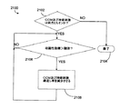
例2において、例1の装置は、(1)再充電パルスが完了するか;(2)心不整脈評価が完了するか;(3)神経刺激が完了するか;又は(4)除細動ショックが完了するか;の内の少なくとも1つがなされるまでCCM療法を延期するよう構成されたコントローラ回路を場合により含む。 In Example 2, the device of Example 1 (1) Recharge pulse is complete; (2) Cardiac arrhythmia assessment is complete; (3) Neural stimulation is complete; or (4) Defibrillation shock Optionally includes a controller circuit configured to postpone CCM therapy until at least one of the following is done.
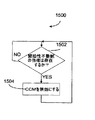
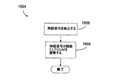
例3において、例1から2までのいずれか1つの装置は、場合により、電気刺激療法回路を含み;前記コントローラ回路は、CCM条件が存在するのかどうかについての情報を使用して電気刺激エネルギーを調整するよう構成される。 In Example 3, any one device of Examples 1 to 2 optionally includes an electrical stimulation therapy circuit; the controller circuit uses the information about whether a CCM condition exists to generate electrical stimulation energy. Configured to adjust.
例4において、例1から3までのいずれか1つの装置は、CCM条件が存在するのかどうかを決定し、(a)CCMが規定の前の時間の間に送達されたか、又は(b)CCMが有効である場合にCCM条件が存在するとみなすように構成されたコントローラを、場合により含む。 In Example 4, any one device from Examples 1 to 3 determines whether a CCM condition exists and (a) the CCM was delivered during a specified previous time, or (b) the CCM Optionally includes a controller that is configured to consider a CCM condition to exist if is valid.
例5において、例1から4までのいずれか1つの装置は、少なくとも1つのCCM条件が存在する場合に電気刺激閾値エネルギーを決定するよう構成されたコントローラを場合により含む。 In Example 5, any one device of Examples 1 through 4 optionally includes a controller configured to determine electrical stimulation threshold energy when at least one CCM condition exists.
例6において、例1から5までのいずれか1つの装置は、少なくとも1つのCCM条件が存在する場合に前記電気刺激閾値エネルギー以上で前記電気刺激療法を送達するよう構成されたコントローラを場合により含む。 In Example 6, any one device of Examples 1-5 optionally includes a controller configured to deliver the electrical stimulation therapy at or above the electrical stimulation threshold energy when at least one CCM condition exists. .
例7において、例1から6までのいずれか1つの装置は、CCM条件が存在しない場合に前記電気刺激閾値エネルギーから誘導された規定のエネルギーで前記電気刺激療法を送
達するよう構成されたコントローラを場合により含む。
In Example 7, any one device of Examples 1-6 includes a controller configured to deliver the electrical stimulation therapy with a defined energy derived from the electrical stimulation threshold energy in the absence of a CCM condition. In some cases included.
例8において、例1から7までのいずれか1つの装置は、CCM条件が存在しない場合に電気刺激閾値エネルギーを決定するよう構成されたコントローラを場合により含む。
例9において、例1から8までのいずれか1つの装置は、少なくとも1つのCCM条件が存在する場合に前記電気刺激閾値エネルギーから誘導された規定のエネルギーで前記電気刺激療法を送達するよう構成されたコントローラを場合により含む。
In Example 8, any one device of Examples 1-7 optionally includes a controller configured to determine the electrical stimulation threshold energy when no CCM condition exists.
In Example 9, any one device of Examples 1-8 is configured to deliver the electrical stimulation therapy with a defined energy derived from the electrical stimulation threshold energy when at least one CCM condition exists. Optional controller.
例10において、例1から9までのいずれか1つの装置は、CCM条件が存在しない場合に前記電気刺激閾値エネルギー以上で前記電気刺激療法を送達するよう構成されたコントローラを場合により含む。 In Example 10, any one device of Examples 1-9 optionally includes a controller configured to deliver the electrical stimulation therapy above the electrical stimulation threshold energy when no CCM condition is present.
例11において、例1から10までのいずれか1つの装置は、場合により電気刺激療法回路を含み;前記コントローラ回路は、再充電パルスを発すること又は結合コンデンサを配置することの内の少なくとも1つによってCCM療法の送達を整えるよう構成される。 In Example 11, any one device of Examples 1 to 10 optionally includes an electrical stimulation therapy circuit; the controller circuit is at least one of issuing a recharge pulse or placing a coupling capacitor Configured to coordinate delivery of CCM therapy.
例12において、例1から11までのいずれか1つの装置は、同じ部位へのCCM療法及び前記再充電パルスの同時送達を停止するよう構成されたコントローラ回路を場合により含む。 In Example 12, any one device of Examples 1 to 11 optionally includes a controller circuit configured to stop simultaneous delivery of CCM therapy and the recharge pulse to the same site.
例13において、例1から12までのいずれか1つの装置は、CCMの送達を始動し、次いで再充電パルスを発することを始動し、その後同じ心周期の間に電気刺激の送達を始動するよう構成されたコントローラ回路を場合により含む。 In Example 13, any one device of Examples 1-12 initiates CCM delivery, then initiates a recharge pulse, and then initiates electrical stimulation delivery during the same cardiac cycle. Optionally includes a configured controller circuit.
例14において、例1から13までのいずれか1つの装置は、再充電を発することを始動し、その後CCM残留電荷を放出するよう構成されたコントローラ回路を場合により含む。 In Example 14, any one of Examples 1-13 optionally includes a controller circuit configured to initiate recharging and then release CCM residual charge.
例15において、例1から14までのいずれか1つの装置は、CCMの送達を始動し、次いで結合コンデンサを配置し、その後電気刺激の送達を始動するように構成されたコントローラ回路を場合により含む。 In Example 15, any one device of Examples 1-14 optionally includes a controller circuit configured to initiate delivery of CCM, then place a coupling capacitor, and then initiate delivery of electrical stimulation. .
例16において、例1から15までのいずれか1つの装置は、電気刺激を送達することを始動し、次いでCCMを送達することを始動し、その後電気刺激及びCCM残留電荷を放出するために再充電を始動するよう構成されたコントローラ回路を場合により含む。 In Example 16, any one device of Examples 1-15 initiates delivery of electrical stimulation, then initiates delivery of CCM, and then re-releases to release electrical stimulation and CCM residual charge. Optionally includes a controller circuit configured to initiate charging.
例17において、例1から16までのいずれか1つの装置は、電気刺激を送達することを始動し、次いでCCMを送達するための結合コンデンサを配置し、次いでCCMを送達することを始動し、次いで電気刺激及びCCM残留電荷を放出するために再充電を始動するよう構成されたコントローラ回路を場合により含む。 In Example 17, any one device from Examples 1-16 initiates delivering electrical stimulation, then places a coupling capacitor to deliver CCM, and then initiates delivery of CCM; A controller circuit is then optionally included that is configured to initiate recharging in order to release electrical stimulation and CCM residual charge.
例18において、例1から17までのいずれか1つの装置は、結合コンデンサにおける残留CCMエネルギーが、電気刺激の間に送達されるエネルギーに付加されるように前記結合コンデンサを配置するよう構成されたコントローラを場合により含む。 In Example 18, any one device of Examples 1-17 was configured to position the coupling capacitor such that residual CCM energy in the coupling capacitor is added to the energy delivered during electrical stimulation. Optionally includes a controller.
例19において、例1から18までのいずれか1つの装置は、場合により、自動閾値回路又は自動キャプチャ回路の内の少なくとも1つを含み;前記コントローラ回路は、CCMが有効であるのかどうかと、以下の:(1)自動閾値又は自動キャプチャの間にCCMを一時停止すること;(2)CCMが非アクティブである場合に自動閾値又は自動キャプチャを実行すること;又は(3)前記CCMと前記自動閾値又は自動キャプチャの内の少
なくとも1つとに非競合電極配置を割り当てること;の内の少なくとも1つを行うために自動キャプチャ又は自動閾値の少なくとも1つが有効であるのかどうかとについての情報を使用するよう構成される。
In Example 19, any one device of Examples 1-18 optionally includes at least one of an automatic threshold circuit or an automatic capture circuit; the controller circuit determines whether CCM is valid; The following: (1) Pause CCM during auto threshold or auto capture; (2) Perform auto threshold or auto capture when CCM is inactive; or (3) The CCM and the Assigning a non-competitive electrode arrangement to at least one of the automatic threshold or automatic capture; using information about whether at least one of the automatic capture or automatic threshold is valid to do at least one of Configured to do.
例20において、例1から19までのいずれか1つの装置は、場合により、自動閾値回路又は自動キャプチャ回路の内の少なくとも1つを含み;前記コントローラ回路は、(1)電気刺激キャプチャ閾値エネルギーの変化を検出する;及び(2)前記電気刺激キャプチャ閾値エネルギーの前記変化についての情報を使用してCCM療法を調整する;ように構成される。 In Example 20, any one device of Examples 1-19 optionally includes at least one of an automatic threshold circuit or an automatic capture circuit; the controller circuit includes: (1) electrical stimulation capture threshold energy And (2) adjusting CCM therapy using information about the change in the electrical stimulation capture threshold energy.
例21において、例1から20までのいずれか1つの装置は、場合により心室電位検知回路を含み;前記心室電位検知回路は、誘発電位又は固有電位の内の少なくとも1つを検知するよう構成され;前記コントローラ回路は、(1)心室電位の大きさ、時間設定又は形態の変化の内の少なくとも1つを含む心室電位の変化を検出し;及び(2)心室電位の変化についての情報を使用してCCM療法を調整する、ように構成される。 In Example 21, any one of Examples 1-20 optionally includes a ventricular potential sensing circuit; wherein the ventricular potential sensing circuit is configured to sense at least one of an evoked potential or an intrinsic potential. Said controller circuit detects (1) a change in ventricular potential including at least one of a magnitude, time setting or morphological change in ventricular potential; and (2) uses information about changes in ventricular potential To configure CCM therapy.
例22において、例1から21までのいずれか1つの装置は、場合により、ペーシング又は除細動閾値決定回路の内の少なくとも1つを含み;前記コントローラ回路は、ペーシング又は除細動閾値試験の内の少なくとも1つの間にCCM療法を制御するよう構成される。 In Example 22, any one device of Examples 1 to 21 optionally includes at least one of a pacing or defibrillation threshold determination circuit; the controller circuit for pacing or defibrillation threshold testing Configured to control CCM therapy during at least one of the two.
例23において、例1から22までのいずれか1つの装置は、ペーシング又は除細動閾値試験の内の少なくとも1つの間にCCM療法を停止するよう構成されたコントローラ回路を場合により含む。 In Example 23, any one device from Examples 1 to 22 optionally includes a controller circuit configured to stop CCM therapy during at least one of a pacing or defibrillation threshold test.
例24において、例1から22までのいずれか1つの装置は、ペーシング又は除細動閾値試験の内の少なくとも1つの間にCCM療法を提供することを始動するよう構成されたコントローラ回路を場合により含む。 In Example 24, any one device of Examples 1 to 22 optionally includes a controller circuit configured to initiate providing CCM therapy during at least one of a pacing or defibrillation threshold test. Including.
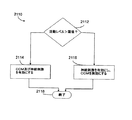
例25において、例1から24までのいずれか1つの装置は、場合により固有心臓信号検知回路を含み;前記コントローラ回路は、前の拍動が、ペーシングされた拍動であったのか又は検知された拍動であったのかに異なって基づいて、CCMエネルギー、CCM送達時間設定、CCM送達部位又はCCM電極配置の内の少なくとも1つを調整することによって、CCM療法送達と固有心臓信号検知とを整えるように配置される。 In Example 25, any one of the devices from Examples 1 to 24 optionally includes an intrinsic cardiac signal detection circuit; the controller circuit detects whether the previous beat was a paced beat. The CCM therapy delivery and intrinsic heart signal detection are adjusted by adjusting at least one of CCM energy, CCM delivery time setting, CCM delivery site or CCM electrode placement based on whether the pulse was Arranged to arrange.
例26において、例1から25までのいずれか1つの装置は、固有拍動の後のCCM送達時間設定と比較して、ペーシングされた拍動の後のCCM送達時間設定を遅延させるよう構成されたコントローラ回路を場合により含む。 In Example 26, any one device of Examples 1-25 is configured to delay the CCM delivery time setting after the paced beat as compared to the CCM delivery time setting after the unique beat. Optional controller circuitry.
例27において、例1から26までのいずれか1つの装置は、場合により固有心臓信号検知回路を含み;前記コントローラ回路は、どの心腔がペーシングされるのかに異なって基づいて、CCMエネルギー、CCM送達時間設定、CCM送達部位又はCCM電極配置の内の少なくとも1つを調整することによって、CCM療法送達と固有心臓信号検知とを整えるよう構成される。 In Example 27, any one device of Examples 1 to 26 optionally includes an intrinsic cardiac signal sensing circuit; the controller circuit determines the CCM energy, CCM based on which heart chamber is being paced It is configured to coordinate CCM therapy delivery and intrinsic cardiac signal detection by adjusting at least one of a delivery time setting, a CCM delivery site, or a CCM electrode placement.
例28において、例1から27までのいずれか1つの装置は、(a)CCM療法が第1心腔に送達され、且つペーシング療法が異なる第2心腔に送達される場合に第1時間設定遅延の後でCCM療法を送達する;及び(b)CCM療法及びペーシング療法が同じ心腔に送達される場合に第2時間設定遅延の後でCCM療法を送達する;ように構成されたコントローラ回路を場合により含み、前記第1時間設定遅延は、前記第2時間設定遅延より
も長い。
In Example 28, any one of the devices from Examples 1 to 27 is configured to: (a) set a first time when CCM therapy is delivered to the first heart chamber and pacing therapy is delivered to a different second heart chamber; A controller circuit configured to deliver CCM therapy after the delay; and (b) deliver CCM therapy after a second time set delay when CCM therapy and pacing therapy are delivered to the same heart chamber; The first time setting delay is longer than the second time setting delay.
例29は、心臓の不応期の間に非刺激性電気エネルギーを送達するよう構成された心筋収縮能調整(CCM)療法回路;頻拍性不整脈を検出すること又は頻拍性不整脈療法を送達することの内の少なくとも1つを含む頻拍性不整脈機能を実行するよう構成された頻拍性不整脈回路;及び前記CCM療法回路及び前記頻拍性不整脈回路に結合されたコントローラ回路であって、CCM療法又は前記頻拍性不整脈機能の内の少なくとも一方を、前記CCM療法又は前記頻拍性不整脈機能の内の他方についての情報を使用して調整するよう構成されたコントローラ回路;を含む植込み型心臓律動/機能管理装置を含む。 Example 29 is a myocardial contractility modulation (CCM) therapy circuit configured to deliver non-stimulatory electrical energy during the cardiac refractory period; detecting tachyarrhythmia or delivering tachyarrhythmia therapy A tachyarrhythmia circuit configured to perform a tachyarrhythmia function including at least one of: a CCM therapy circuit and a controller circuit coupled to the tachyarrhythmia circuit comprising: An implantable heart comprising: a controller circuit configured to adjust at least one of therapy or the tachyarrhythmia function using information about the other of the CCM therapy or the tachyarrhythmia function; Includes rhythm / function management device.
例30において、例29の装置は、ショック療法を送達するよう構成されたショック療法回路を場合により含み;前記コントローラ回路は、ショック療法送達の間にショック療法回路からCCM療法回路を切り離すように構成される。 In Example 30, the apparatus of Example 29 optionally includes a shock therapy circuit configured to deliver shock therapy; the controller circuit configured to decouple the CCM therapy circuit from the shock therapy circuit during shock therapy delivery Is done.
例31において、例29又は30の内のいずれか1つの装置は、固有心臓信号形態解析回路を使用して頻拍性不整脈を検出するよう構成された頻拍性不整脈回路を場合により含み;前記コントローラ回路は、CCM条件が存在するのかどうかについての情報を使用して前記形態解析を調整するよう構成され;及びCCM条件は、(a)CCMが規定の前の時間の間に送達されたか、又は(b)CCMが有効である場合に存在するとみなされる。 In Example 31, the apparatus of any one of Examples 29 or 30 optionally includes a tachyarrhythmia circuit configured to detect tachyarrhythmia using an intrinsic cardiac signal form analysis circuit; The controller circuit is configured to adjust the morphological analysis using information about whether a CCM condition exists; and the CCM condition is: (a) whether the CCM was delivered during a specified previous time; Or (b) Present if CCM is valid.
例32において、例29から31までのいずれか1つの装置は、CCM条件が存在するのかどうかに基づいて形態テンプレートを選択するよう構成されたコントローラ回路を場合により含む。 In Example 32, any one device of Examples 29-31 optionally includes a controller circuit configured to select a configuration template based on whether a CCM condition exists.
例33において、例29から32までのいずれか1つの装置は、CCMが有効である場合、前記コントローラ回路が、有効にされたCCMによって得られた形態テンプレートを選択するよう構成されるように配置されたコントローラを場合により含む。 In Example 33, any one of the devices from Examples 29 to 32 is arranged such that if the CCM is valid, the controller circuit is configured to select a configuration template obtained by the enabled CCM. Optionally includes a designated controller.
例34において、例29から33までの内の1つの装置は、CCM条件が存在する場合に形態解析が無効にされるように配置されたコントローラを場合により含む。
例35は、心臓の不応期の間に非刺激性電気エネルギーを送達するよう構成された心筋収縮能調整(CCM)療法回路;生理学的パラメータを検知するよう構成された生理学的検知回路;及び前記CCM療法回路及び前記生理学的検知回路に結合されたコントローラ回路であって、検知された前記生理学的パラメータについての情報を使用してCCM療法を調整するよう構成されたコントローラ回路;を備えた植込み型心臓律動/機能管理装置を含む。
In Example 34, one of the devices in Examples 29-33 optionally includes a controller that is arranged such that morphological analysis is disabled when a CCM condition exists.
Example 35 includes a myocardial contractility modulation (CCM) therapy circuit configured to deliver non-stimulatory electrical energy during a cardiac refractory period; a physiological sensing circuit configured to sense a physiological parameter; and A controller circuit coupled to the CCM therapy circuit and the physiological sensing circuit, the controller circuit configured to adjust CCM therapy using information about the sensed physiological parameter; Includes a cardiac rhythm / function management device.
例36において、例35の装置は、腎機能又は心臓機能の内の少なくとも1つの測定の指標を検知するよう構成された生理学的検知回路を場合により含む。
例37において、例35から36までのいずれか1つの装置は、CCMエネルギー、CCM送達時間設定、CCM送達部位又はCCM電極配置の内の少なくとも1つを調整するために腎機能又は心臓機能についての情報を使用するよう構成されたコントローラ回路を場合により含む。
In Example 36, the apparatus of Example 35 optionally includes a physiological sensing circuit configured to sense an indication of at least one of renal function or cardiac function.
In Example 37, any one of the devices of Examples 35 to 36 may be used for renal or cardiac function to adjust at least one of CCM energy, CCM delivery time setting, CCM delivery site or CCM electrode placement. Optionally includes a controller circuit configured to use the information.
例38において、例35から37までのいずれか1つの装置は、カリウム、ナトリウム、カルシウム、クロリド又はバイカルボネートの内の少なくとも1つの測定の指標を検出するよう構成された電解質検知器を場合により含む。 In Example 38, any one device of Examples 35-37 optionally includes an electrolyte detector configured to detect an indication of at least one of potassium, sodium, calcium, chloride, or bicarbonate. .
例39において、例35から38までのいずれか1つの装置は、CCMエネルギー、CCM送達時間設定、CCM送達部位又はCCM電極配置の内の少なくとも1つを調整する
ためにカリウム、ナトリウム、カルシウム、クロリド又はバイカルボネートの内の少なくとも1つの測定についての情報を使用するよう構成されたコントローラ回路を場合により含む。
In Example 39, any one of the devices of Examples 35-38 may include potassium, sodium, calcium, chloride to adjust at least one of CCM energy, CCM delivery time setting, CCM delivery site or CCM electrode placement. Or optionally including a controller circuit configured to use information about at least one measurement of the bicarbonate.
例40において、例35から39までのいずれか1つの装置は、血中尿素窒素、血清クレアチニン又は糸球体濾過率の内の少なくとも1つの測定の指標を検出するよう構成された生理学的検知回路を場合により含む。 In Example 40, any one of the devices of Examples 35 to 39 includes a physiological sensing circuit configured to detect an indicator of at least one measurement of blood urea nitrogen, serum creatinine or glomerular filtration rate. In some cases included.
例41において、例35から40までのいずれか1つの装置は、CCMエネルギー、CCM送達時間設定、CCM送達部位又はCCM電極配置の内の少なくとも1つを調整するために血中尿素窒素、血清クレアチニン又は糸球体濾過率の内の前記少なくとも1つの前記測定についての情報を使用するよう構成されたコントローラ回路を場合により含む。 In Example 41, any one of the devices of Examples 35 to 40 can be used to adjust blood urea nitrogen, serum creatinine to adjust at least one of CCM energy, CCM delivery time setting, CCM delivery site or CCM electrode placement. Or optionally including a controller circuit configured to use information about the at least one of the measurements of glomerular filtration rate.
例42において、例35から41までのいずれか1つの装置は、神経信号を検知するよう構成された神経検知器を場合により含む。
例43において、例35から42までのいずれか1つの装置は、CCMエネルギー、CCM送達時間設定、CCM送達部位又はCCM電極配置の内の少なくとも1つを調整するために前記神経信号についての情報を使用するよう構成されたコントローラ回路を場合により含む。
In Example 42, any one device of Examples 35-41 optionally includes a nerve detector configured to detect a nerve signal.
In Example 43, any one of the devices from Examples 35 to 42 may provide information about the neural signal to adjust at least one of CCM energy, CCM delivery time setting, CCM delivery site or CCM electrode placement. Optionally includes a controller circuit configured for use.
例44において、例35から43までのいずれか1つの装置は、迷走神経からの神経信号を検知するよう構成された神経検知器を場合により含み;前記迷走神経からの前記神経信号は、迷走神経活性の増加又は低下の内の1つの指標を含む。 In Example 44, any one device of Examples 35-43 optionally includes a nerve detector configured to detect a nerve signal from the vagus nerve; the nerve signal from the vagus nerve is Includes one of the increases or decreases in activity.
例45において、例35から44までのいずれか1つの装置は、前記神経信号が迷走神経活性の増加を示す場合、前記コントローラ回路がCCMエネルギー又はCCM送達の周波数の内の少なくとも1つを増加させるよう構成されるように配置されたコントローラ回路を場合により含む。 In Example 45, any one of the devices of Examples 35 to 44, wherein the controller circuit increases at least one of CCM energy or frequency of CCM delivery if the neural signal indicates an increase in vagus nerve activity. Optionally includes a controller circuit arranged to be configured as such.
例46において、例35から45までのいずれか1つの装置は、交感神経活性又は副交感神経活性の内の少なくとも1つをモニタするよう構成された神経検知器を場合により含み;前記神経信号は、交感神経活性の増加、交感神経活性の低下、副交感神経活性の増加、又は副交感神経活性の低下の内の少なくとも1つの指標を含む。 In Example 46, any one of the devices of Examples 35 to 45 optionally includes a neural detector configured to monitor at least one of sympathetic or parasympathetic activity; It includes at least one indicator of increased sympathetic activity, decreased sympathetic activity, increased parasympathetic activity, or decreased parasympathetic activity.
例47において、例35から46までのいずれか1つの装置は、前記神経信号が、副交感神経活性の増加又は交感神経活性の低下の内の少なくとも1つを示す場合、コントローラ回路が、CCMエネルギー又はCCM送達の周波数の内の少なくとも1つを増加させるよう構成されるように配置されたコントローラ回路を場合により含む。 In Example 47, any one of the devices of Examples 35 to 46 may be configured such that if the neural signal exhibits at least one of an increase in parasympathetic activity or a decrease in sympathetic activity, the controller circuit can detect CCM energy or Optionally includes a controller circuit arranged to be configured to increase at least one of the frequencies of the CCM delivery.
例48において、例35から47までのいずれか1つの装置は、前記神経信号が、交感神経活性の増加又は副交感神経活性の低下の内の少なくとも1つを示す場合、前記コントローラ回路が、CCMエネルギー又はCCM送達の周波数の内の少なくとも1つを低下させるよう構成されるように配置されたコントローラ回路を場合により含む。 In Example 48, any one of the devices of Examples 35 to 47 may be configured such that, if the neural signal indicates at least one of an increase in sympathetic activity or a decrease in parasympathetic activity, the controller circuit includes CCM energy Or optionally including a controller circuit arranged to be configured to reduce at least one of the frequencies of the CCM delivery.
例49において、例35から48までのいずれか1つの装置は、神経刺激療法を送達するよう構成された神経刺激回路を場合により含む。
例50において、例35から49までのいずれか1つの装置は、前記CCM療法又は前記神経刺激療法の内の少なくとも一方を、前記CCM療法又は前記神経刺激療法の内の他方についての情報を使用して調整するよう構成されたコントローラ回路を場合により含む。
In Example 49, any one of the devices of Examples 35 to 48 optionally includes a neural stimulation circuit configured to deliver neural stimulation therapy.
In Example 50, the device of any one of Examples 35 to 49 uses information about at least one of the CCM therapy or the neural stimulation therapy and information about the other of the CCM therapy or the neural stimulation therapy. Optionally includes a controller circuit configured to adjust.
例51において、例35から50までのいずれか1つの装置は、検知された前記生理学的パラメータについての情報を使用して前記CCM療法又は前記神経刺激療法の内の少なくとも1つを調整するよう構成されたコントローラ回路を場合により含む。 In Example 51, any one device of Examples 35 to 50 is configured to adjust at least one of the CCM therapy or the neural stimulation therapy using information about the sensed physiological parameter. Optionally includes a controller circuit.
例52は、心臓の不応期の間に非刺激性電気エネルギーを送達するよう構成された心筋収縮能調整(CCM)療法回路;有害事象検出回路;及び前記CCM療法回路及び前記有害事象検出回路に結合されたコントローラ回路であって、前記有害事象検出回路からの有害事象についての情報を使用してCCM療法を調整するよう構成されたコントローラ回路;を備えた植込み型心臓律動/機能管理装置を含む装置を含む。 Example 52 includes a myocardial contractility modulation (CCM) therapy circuit configured to deliver non-stimulatory electrical energy during a cardiac refractory period; an adverse event detection circuit; and the CCM therapy circuit and the adverse event detection circuit. An implantable cardiac rhythm / function management device comprising: a controller circuit coupled to the controller circuit configured to adjust CCM therapy using information about adverse events from the adverse event detection circuit; Including equipment.
例53において、例52の装置は、非CCM療法を送達するよう構成された非CCM療法回路を場合により含み;前記有害事象検出回路は、バッテリ状態回路を含み;及び前記コントローラ回路は、多数のバッテリの内のどれが前記非CCM療法回路又は前記CCM療法回路の内の少なくとも1つにサービスを提供するのかを再構成するための前記バッテリ状態回路から得られたバッテリ状態情報を使用するよう構成される。 In Example 53, the apparatus of Example 52 optionally includes a non-CCM therapy circuit configured to deliver non-CCM therapy; the adverse event detection circuit includes a battery status circuit; and the controller circuit includes a plurality of Configured to use battery status information obtained from the battery status circuit to reconfigure which of the batteries serve at least one of the non-CCM therapy circuit or the CCM therapy circuit Is done.
例54において、例52又は53の内のいずれか1つの装置は、非CCM療法を送達するよう構成された非CCM療法回路を場合により含み;前記有害事象検出回路は、バッテリ状態回路を含み;及び前記コントローラ回路は、前記CCM療法又は前記非CCM療法の内の一方の送達を、前記CCM療法又は前記非CCM療法の内の他方よりも優先的に終了するために前記バッテリ状態回路から得られたバッテリ状態情報を使用するよう構成される。 In Example 54, any one of the devices of Examples 52 or 53 optionally includes a non-CCM therapy circuit configured to deliver non-CCM therapy; the adverse event detection circuit includes a battery status circuit; And the controller circuit is obtained from the battery status circuit to preferentially terminate delivery of one of the CCM therapy or the non-CCM therapy over the other of the CCM therapy or the non-CCM therapy. Configured to use the battery status information.
例55において、例52から54までのいずれか1つの装置は、神経刺激療法を送達するよう構成された神経刺激療法回路を場合により含み;前記有害事象検出回路は、神経刺激又はCCMの内の少なくとも1つに関連する有害事象を検出するよう構成され;及び前記コントローラ回路は、前記有害事象検出回路からの情報に基づいて前記CCM療法又は前記神経刺激療法の内の少なくとも1つを調整するよう構成される。 In Example 55, any one device of Examples 52-54 optionally includes a neural stimulation therapy circuit configured to deliver neural stimulation therapy; the adverse event detection circuit is within neural stimulation or CCM Configured to detect an adverse event associated with at least one; and the controller circuit adjusts at least one of the CCM therapy or the neural stimulation therapy based on information from the adverse event detection circuit Composed.
例56において、例52から55までのいずれか1つの装置は、神経刺激が有効であり、且つ前記神経刺激に関連する有害事象が発現する場合、次いで前記コントローラ回路が、(a)CCMが有効である場合に神経刺激をオフにする;(b)CCMが有効でなく、且つ神経刺激を無効にしない場合にCCMを有効にする;又は(c)CCMが有効でなく、且つ神経刺激を無効にする場合にCCMを有効にする、ように配置されたコントローラ回路を場合により含む。 In Example 56, if any one of the devices of Examples 52-55 is effective for neural stimulation and an adverse event associated with the neural stimulation occurs, then the controller circuit: (a) CCM enabled Turn off neural stimulation if (b) CCM is not effective and do not disable neural stimulation; or (c) CCM is not effective and disable neural stimulation Optionally includes a controller circuit arranged to enable the CCM.
例57において、例52から56までのいずれか1つの装置は、CCMが有効であり、且つ前記CCMに関連する有害事象が発現する場合、次いで前記コントローラ回路が、(a)神経刺激が有効である場合にCCMをオフにする;(b)神経刺激が有効でなく、且つCCMを無効にしない場合に神経刺激をオンにする;又は(c)神経刺激が有効でなく、且つCCMを無効にする場合に神経刺激を有効にする、ように配置されたコントローラ回路を場合により含む。 In Example 57, any one of the devices of Examples 52 through 56 may be configured such that if CCM is effective and an adverse event associated with the CCM occurs, then the controller circuit: (a) Neural stimulation is enabled Turn off CCM in some cases; (b) Turn on nerve stimulation when nerve stimulation is not effective and do not disable CCM; or (c) Disable nerve stimulation and disable CCM Optionally includes a controller circuit arranged to enable neural stimulation.
例58において、例52から57までのいずれか1つの装置は、生理学的検知器を含む有害事象検出器を場合により含む。
例59において、例52から58までのいずれか1つの装置は、交互脈を検出するよう構成された生理学的検知器を場合により含み;前記コントローラは、交互脈の検出に応答してCCMエネルギー、CCM送達時間設定、CCM送達部位又はCCM電極配置の内の少なくとも1つを調整するよう構成される。
In Example 58, any one device of Examples 52-57 optionally includes an adverse event detector including a physiological detector.
In Example 59, any one device of Examples 52-58 optionally includes a physiological detector configured to detect an alternan; the controller responds to the detection of the alternan with CCM energy; It is configured to adjust at least one of a CCM delivery time setting, a CCM delivery site, or a CCM electrode placement.
例60において、例52から59までのいずれか1つの装置は、交互脈の検出に応答してCCMエネルギー又はCCM送達の周波数の内の少なくとも1つを増加させるよう構成されたコントローラを場合により含む。 In Example 60, any one device of Examples 52-59 optionally includes a controller configured to increase at least one of CCM energy or CCM delivery frequency in response to detection of an alternan. .
例61において、例52から60までのいずれか1つの装置は、前記有害事象についての使用者入力情報を受信するために使用者インタフェースを含む前記有害事象検出回路を場合により含む。 In Example 61, any one apparatus of Examples 52-60 optionally includes the adverse event detection circuit including a user interface to receive user input information about the adverse event.
例62において、例52から61までのいずれか1つの装置は、CCMを有効にするためのCCM始動条件を検出するよう構成されたCCM始動検出回路を含む有害事象検出回路を場合により含み;前記コントローラ回路は、少なくとも1つのCCM始動が検出される場合に前記CCM療法を有効にするよう構成される。 In Example 62, any one device of Examples 52 through 61 optionally includes an adverse event detection circuit that includes a CCM start detection circuit configured to detect a CCM start condition to enable CCM; The controller circuit is configured to enable the CCM therapy when at least one CCM start is detected.
例63において、例52から62までのいずれか1つの装置は、心不全の増悪の指標、腎機能の増悪の指標、血行動態状態の増悪の指標、規定値の範囲の上若しくは下にある生理学的パラメータの測定の指標、呼吸困難の指標、規定閾値の下にある検出された身体活動レベル、又はCCM療法以外の装置に基づく心不全療法の有効若しくは無効の指標の内の少なくとも1つを含むCCM始動条件を場合により含む。 In Example 63, any one of the devices of Examples 52-62 may be used to indicate an indication of heart failure exacerbation, an indication of an exacerbation of renal function, an indication of an exacerbation of hemodynamic status, a physiological condition that is above or below a specified range. CCM initiation including at least one of a parameter measurement index, a dyspnea index, a detected physical activity level below a defined threshold, or a valid or ineffective index of heart failure therapy based on a device other than CCM therapy Conditions are included in some cases.
例64において、例52から63までのいずれか1つの装置は、心不全の増悪の指標を含むCCM始動条件を場合により含む。
例65において、例52から64までのいずれか1つの装置は、CCM療法以外の装置に基づく心不全療法の有効又は無効の指標を含むCCM始動条件を場合により含む。
In Example 64, any one device of Examples 52-63 optionally includes a CCM start condition that includes an indication of an exacerbation of heart failure.
In Example 65, any one device of Examples 52-64 optionally includes a CCM start condition that includes an indication of the effectiveness or ineffectiveness of heart failure therapy based on a device other than CCM therapy.
例66において、例52から65までのいずれか1つの装置は、CCMを無効にするためのCCMストレッサを検出するよう構成されたCCMストレッサ検出回路を含む有害事象検出回路を場合により含み;前記コントローラ回路は、少なくとも1つのCCMストレッサが検出される場合にCCMを無効にするよう構成される。 In Example 66, any one device of Examples 52 through 65 optionally includes an adverse event detection circuit including a CCM stressor detection circuit configured to detect a CCM stressor for disabling CCM; The circuit is configured to disable the CCM when at least one CCM stressor is detected.
例67において、例52から66までのいずれか1つの装置は、睡眠呼吸障害の検出、検出された心筋虚血、検出された心筋梗塞、心不全状態の改善の指標、規定値の範囲の上若しくは下にある生理学的パラメータの測定の指標、CCM療法以外の装置に基づく心不全療法の有効若しくは無効の指標、検出された心不整脈、規定閾値を超える検出された身体活動レベル、又は検出された磁気共鳴イメージングの内の少なくとも1つを含むCCMストレッサ条件を場合により含む。 In Example 67, any one of the devices of Examples 52 through 66 may be used to detect sleep breathing disorders, detected myocardial ischemia, detected myocardial infarction, an indication of improvement in heart failure status, over a specified range Indicator of measurement of underlying physiological parameter, indication of effectiveness or ineffectiveness of heart failure therapy based on a device other than CCM therapy, detected cardiac arrhythmia, detected physical activity level above specified threshold, or detected magnetic resonance Optionally includes a CCM stressor condition that includes at least one of the imaging.
例68において、例52から67までのいずれか1つの装置は、CCM療法以外の装置に基づく心不全療法の有効又は無効の指標を含むCCMストレッサ条件を場合により含む。 In Example 68, any one device of Examples 52-67 optionally includes a CCM stressor condition that includes an indication of the effectiveness or ineffectiveness of heart failure therapy based on a device other than CCM therapy.
例69において、例52から68までのいずれか1つの装置は、規定閾値を超える検出された身体活動レベルを含む前記CCMストレッサ条件を場合により含む。
例70において、例52から69までのいずれか1つの装置は、CCMを有効にするためのCCM始動条件を検出するよう構成されたCCM始動検出回路と、CCMを無効にするためのCCMストレッサを検出するよう構成されたCCMストレッサ検出回路とを含む有害事象検出回路を場合により含み;前記コントローラ回路は、少なくとも1つのCCM始動が検出される場合にCCM療法を有効にするために、及び少なくとも1つのCCMストレッサが検出される場合にCCMを無効にするよう構成される。
In Example 69, any one device of Examples 52-68 optionally includes the CCM stressor condition that includes a detected physical activity level that exceeds a specified threshold.
In Example 70, any one of Examples 52-69 includes a CCM start detection circuit configured to detect a CCM start condition for enabling CCM, and a CCM stressor for disabling CCM. An adverse event detection circuit, optionally including a CCM stressor detection circuit configured to detect; the controller circuit to enable CCM therapy if at least one CCM activation is detected; and at least one The CCM is configured to be invalidated when two CCM stressors are detected.
例71において、例52から70までのいずれか1つの装置は、心不全の増悪の指標、腎機能の増悪の指標、血行動態状態の増悪の指標、規定値の範囲の上若しくは下にある生理学的パラメータの測定の指標、呼吸困難の指標、規定閾値の下にある検出された身体活動レベル、又はCCM療法以外の装置に基づく心不全療法の有効若しくは無効の指標の内の少なくとも1つを含むCCM始動条件を場合により含む。 In Example 71, any one of the devices of Examples 52 to 70 may be used to indicate an indication of heart failure exacerbation, an indication of exacerbation of renal function, an indication of exacerbation of hemodynamic status, a physiological condition that is above or below a specified range. CCM initiation including at least one of a parameter measurement index, a dyspnea index, a detected physical activity level below a defined threshold, or a valid or ineffective index of heart failure therapy based on a device other than CCM therapy Conditions are included in some cases.
例72において、例52から71までのいずれか1つの装置は、心不全の増悪の指標を含むCCM始動条件を場合により含む。
例73において、例52から72までのいずれか1つの装置は、CCM療法以外の装置に基づく心不全療法の有効又は無効の指標を含むCCM始動条件を場合により含む。
In Example 72, any one device of Examples 52-71 optionally includes a CCM start condition that includes an indication of an exacerbation of heart failure.
In Example 73, any one device of Examples 52-72 optionally includes a CCM start condition that includes an indication of the effectiveness or ineffectiveness of heart failure therapy based on a device other than CCM therapy.
例74において、例52から73までのいずれか1つの装置は、睡眠呼吸障害の検出、検出された心筋虚血、検出された心筋梗塞、心不全状態の改善の指標、規定値の範囲の上若しくは下にある生理学的パラメータの測定の指標、CCM療法以外の装置に基づく心不全療法の有効若しくは無効の指標、検出された心不整脈、規定閾値を超える検出された身体活動レベル、又は検出された磁気共鳴イメージングの内の少なくとも1つを含むCCMストレッサ条件を場合により含む。 In Example 74, any one of the devices from Examples 52 to 73 is used to detect sleep breathing disorder, detected myocardial ischemia, detected myocardial infarction, an indication of improvement in heart failure status, over a range of prescribed values, Indicator of measurement of underlying physiological parameter, indication of effectiveness or ineffectiveness of heart failure therapy based on a device other than CCM therapy, detected cardiac arrhythmia, detected physical activity level above specified threshold, or detected magnetic resonance Optionally includes a CCM stressor condition that includes at least one of the imaging.
例75において、例52から74までのいずれか1つの装置は、CCM療法以外の装置に基づく心不全療法の有効又は無効の指標を含む前記CCMストレッサ条件を場合により含む。 In Example 75, any one device of Examples 52-74 optionally includes the CCM stressor condition that includes an indication of the effectiveness or ineffectiveness of heart failure therapy based on a device other than CCM therapy.
例76において、例52から75までのいずれか1つの装置は、規定閾値を超える検出された身体活動レベルを含む前記CCMストレッサ条件を場合により含む。
例77は、心筋収縮能調整(CCM)療法を送達することを含む方法を含み、前記CCM療法を送達することは、心臓の不応期の間に非刺激性電気エネルギーを送達すること;非CCM療法を送達すること;及び前記CCM療法又は前記非CCM療法の内の少なくとも一方を、前記CCM療法又は前記非CCM療法の内の他方についての情報を使用して調整すること;を含む。
In Example 76, any one device of Examples 52-75 optionally includes the CCM stressor condition that includes a detected physical activity level that exceeds a specified threshold.
Example 77 includes a method comprising delivering a myocardial contractility modulation (CCM) therapy, wherein delivering the CCM therapy delivers non-stimulatory electrical energy during a cardiac refractory period; Delivering a therapy; and adjusting at least one of the CCM therapy or the non-CCM therapy using information about the other of the CCM therapy or the non-CCM therapy.
例78において、例77の方法は、(1)再充電パルスが完了するか;(2)心不整脈評価が完了するか;(3)神経刺激が完了するか;又は(4)除細動ショックが完了するかの内の少なくとも1つがなされるまで前記CCM療法を送達することを延期することを場合により含む。 In Example 78, the method of Example 77 includes: (1) recharging pulse is complete; (2) cardiac arrhythmia assessment is complete; (3) neural stimulation is complete; or (4) defibrillation shock. Optionally delaying delivery of the CCM therapy until at least one of is completed.
例79において、例77又は78のいずれか1つの方法は、場合により電気刺激療法を送達することを含み;前記CCM療法又は前記非CCM療法の内の少なくとも1つを調整することは、CCM条件が存在するのかどうかについての情報を使用して電気刺激エネルギーを調整することを含む。 In Example 79, the method of any one of Examples 77 or 78 optionally includes delivering electrical stimulation therapy; adjusting at least one of the CCM therapy or the non-CCM therapy is a CCM condition Including adjusting the electrical stimulation energy using information about whether or not it is present.
例80において、例77から79までのいずれか1つの方法は、(a)CCMが規定の前の時間の間に送達されたか、又は(b)CCMが有効である場合にCCM条件が存在するとみなすことを場合により含む。 In Example 80, any one of the methods from Examples 77 to 79 can be used if (a) the CCM was delivered during a specified previous time, or (b) a CCM condition exists if the CCM is valid. Including cases to consider.
例81において、例77から80までのいずれか1つの方法は、少なくとも1つのCCM条件が存在する場合に電気刺激閾値エネルギーを決定することを場合により含む。
例82において、例77から81までのいずれか1つの方法は、少なくとも1つのCCM条件が存在する場合に前記電気刺激閾値エネルギー以上で前記非CCM電気刺激療法を送達することを場合により含む。
In Example 81, any one method of Examples 77 through 80 optionally includes determining an electrical stimulation threshold energy when at least one CCM condition exists.
In Example 82, any one method of Examples 77-81 optionally includes delivering the non-CCM electrical stimulation therapy at or above the electrical stimulation threshold energy when at least one CCM condition is present.
例83において、例77から82までのいずれか1つの方法は、CCM条件が存在しない場合に前記電気刺激閾値エネルギーから誘導された規定のエネルギーで前記電気刺激療法を送達することを場合により含む。 In Example 83, any one of the methods from Examples 77 to 82 optionally includes delivering the electrical stimulation therapy with a defined energy derived from the electrical stimulation threshold energy when no CCM condition is present.
例84において、例77から83までのいずれか1つの方法は、CCM条件が存在しない場合に電気刺激閾値エネルギーを決定することを場合により含む。
例85において、例77から84までのいずれか1つの方法は、少なくとも1つのCCM条件が存在する場合に前記電気刺激閾値エネルギーから誘導された規定のエネルギーで電気刺激療法を送達することを場合により含む。
In Example 84, any one method of Examples 77-83 optionally includes determining an electrical stimulation threshold energy when no CCM condition exists.
In Example 85, any one of the methods of Examples 77-84 optionally comprises delivering electrical stimulation therapy with a defined energy derived from the electrical stimulation threshold energy when at least one CCM condition is present. Including.
例86において、例77から85までのいずれか1つの方法は、CCM条件が存在しない場合に前記電気刺激閾値エネルギー以上で前記電気刺激療法を送達することを場合により含む。 In Example 86, any one of the methods from Examples 77 to 85 optionally includes delivering the electrical stimulation therapy at or above the electrical stimulation threshold energy in the absence of CCM conditions.
例87において、例77から86までのいずれか1つの方法は、電気刺激療法を送達することを含む前記非CCM療法を送達することを場合により含み;前記CCM療法を送達することは、再充電パルスを発すること又は結合コンデンサを配置することの内の少なくとも1つによってCCM療法を整えることを含む。 In Example 87, any one of the methods from 77 to 86 optionally includes delivering the non-CCM therapy comprising delivering electrical stimulation therapy; delivering the CCM therapy comprises recharging Arranging CCM therapy by at least one of pulsing or placing a coupling capacitor.
例88において、例77から87までのいずれか1つの方法は、同じ部位へのCCM療法及び前記再充電パルスの同時送達を停止することを場合により含む。
例89において、例77から88までのいずれか1つの方法は、CCMの送達を始動すること、次いで再充電パルスを発することを始動すること、その後同じ心周期の間に電気刺激の送達を始動することを場合により含む。
In Example 88, any one method of Examples 77-87 optionally includes stopping CCM therapy and simultaneous delivery of the recharge pulse to the same site.
In Example 89, any one of the methods of Examples 77 through 88 initiates CCM delivery, then initiates a recharge pulse, and then initiates electrical stimulation delivery during the same cardiac cycle. To include in some cases.
例90において、例77から89までのいずれか1つの方法は、再充電を発することを始動すること、その後CCM残留電荷を放出することを場合により含む。
例91において、例77から90までのいずれか1つの方法は、CCMの送達を始動すること、次いで結合コンデンサを配置すること、その後電気刺激の送達を始動することを場合により含む。
In Example 90, any one method of Examples 77-89 optionally includes initiating a recharge to be emitted and then releasing a CCM residual charge.
In Example 91, any one method of Examples 77-90 optionally includes initiating CCM delivery, then placing a binding capacitor, and then initiating electrical stimulation delivery.
例92において、例77から91までのいずれか1つの方法は、電気刺激の送達を始動すること、次いでCCMを送達することを始動すること、その後電気刺激及びCCM残留電荷を放出するために再充電を始動することを場合により含む。 In Example 92, any one of the methods of Examples 77-91 can be used to initiate delivery of electrical stimulation, then to initiate delivery of CCM, and then re-release to release electrical stimulation and CCM residual charge. Optionally including initiating charging.
例93において、例77から92までのいずれか1つの方法は、電気刺激の送達を始動すること、次いでCCMを送達するための結合コンデンサを配置すること、次いでCCMを送達することを始動すること、次いで電気刺激及びCCM残留電荷を放出するために再充電を始動することを場合により含む。 In Example 93, any one of the methods from Examples 77 to 92 initiates the delivery of electrical stimulation, then places a coupling capacitor to deliver the CCM, and then initiates the delivery of the CCM. And then optionally initiating recharging to release electrical stimulation and CCM residual charge.
例94において、例77から93までのいずれか1つの方法は、結合コンデンサにおける残留CCMエネルギーが、電気刺激の間に送達されるエネルギーに付加されるように前記結合コンデンサを配置することを場合により含む。 In Example 94, any one of the methods from Examples 77 to 93 optionally arranges the coupling capacitor such that residual CCM energy in the coupling capacitor is added to the energy delivered during electrical stimulation. Including.
例95において、例77から94までのいずれか1つの方法は、場合により、自動閾値機能又は自動キャプチャ機能の内の少なくとも1つを実行することを含み;前記CCM療法又は前記非CCM療法の内の少なくとも1つを調整することは、CCM療法が有効であるのかどうかと、自動閾値又は自動キャプチャの内の少なくとも1つが、以下の:(1)自動閾値又は自動キャプチャの間にCCMを一時停止すること;(2)CCMが非アクティブである場合に自動閾値又は自動キャプチャを実行すること;又は(3)前記CCMと
前記自動閾値又は自動キャプチャの内の少なくとも1つとに非競合電極配置を割り当てること;の内の少なくとも1つを行うために有効であるのかどうかとについての情報を使用することを含む。
In Example 95, any one of Examples 77-94 optionally includes performing at least one of an automatic threshold function or an automatic capture function; within the CCM therapy or the non-CCM therapy Adjusting at least one of the following is whether CCM therapy is effective and at least one of the auto threshold or auto capture is: (1) pause CCM during auto threshold or auto capture (2) performing an automatic threshold or automatic capture when the CCM is inactive; or (3) assigning a non-competing electrode arrangement to the CCM and at least one of the automatic threshold or automatic capture. Using information about whether it is valid to do at least one of the following:
例96において、例77から95までのいずれか1つの方法は、場合により、自動閾値機能又は自動キャプチャ機能の内の少なくとも1つを実行することを含み;前記CCM療法又は前記非CCM療法の内の少なくとも1つを調整することは、(1)電気刺激キャプチャ閾値エネルギーの変化を検出すること;及び(2)前記電気刺激キャプチャ閾値エネルギーの前記変化についての情報を使用してCCM療法を調整すること;を含む。 In Example 96, any one of Examples 77-95 optionally includes performing at least one of an automatic threshold function or an automatic capture function; within the CCM therapy or the non-CCM therapy Adjusting at least one of: (1) detecting a change in electrical stimulation capture threshold energy; and (2) adjusting CCM therapy using information about the change in the electrical stimulation capture threshold energy Including.
例97において、例77から96までのいずれか1つの方法は、場合により、誘発電位又は固有電位の内の少なくとも1つを検知することを含み;前記CCM療法又は前記非CCM療法の内の少なくとも1つを調整することは、(1)少なくとも1つの誘発電位又は固有電位の変化であって、前記少なくとも1つの誘発電位又は固有電位の大きさ、時間設定又は形態の変化の内の少なくとも1つを含む変化を検出すること;及び(2)前記少なくとも1つの誘発電位又は固有電位の変化についての情報を使用してCCM療法を調整すること;を含む。 In Example 97, any one of the methods 77-96 optionally includes detecting at least one of an evoked potential or intrinsic potential; at least one of the CCM therapy or the non-CCM therapy Adjusting one is (1) a change in at least one evoked potential or intrinsic potential, wherein at least one of the changes in magnitude, time setting or morphology of the at least one evoked potential or intrinsic potential. And (2) adjusting CCM therapy using information about changes in the at least one evoked potential or eigenpotential.
例98において、例77から97までのいずれか1つの方法は、場合により、ペーシング又は除細動閾値の内の少なくとも1つを決定することを含み;前記CCM療法又は前記非CCM療法の内の少なくとも1つを調整することは、ペーシング又は除細動閾値試験の内の少なくとも1つの間にCCM療法を制御することを含む。 In Example 98, any one of Examples 77-97 optionally includes determining at least one of a pacing or defibrillation threshold; within the CCM therapy or the non-CCM therapy Adjusting at least one includes controlling CCM therapy during at least one of a pacing or defibrillation threshold test.
例99において、例77から98までのいずれか1つの方法は、ペーシング又は除細動閾値試験の内の少なくとも1つの間にCCM療法を停止することを場合により含む。
例100において、例77から99までのいずれか1つの方法は、ペーシング又は除細動閾値試験の内の少なくとも1つの間にCCM療法を提供することを始動することを場合により含む。
In Example 99, any one method of Examples 77-98 optionally includes stopping CCM therapy during at least one of a pacing or defibrillation threshold test.
In Example 100, any one method of Examples 77-99 optionally includes initiating providing CCM therapy during at least one of a pacing or defibrillation threshold test.
例101において、例77から100までのいずれか1つの方法は、場合により、固有心臓信号を検知することを含み;前記CCM療法又は前記非CCM療法の内の少なくとも1つを調整することは、前の拍動が、ペーシングされた拍動であったのか又は検知された拍動であったのかに異なって基づいて、CCMエネルギー、CCM送達時間設定、CCM送達部位又はCCM電極配置の内の少なくとも1つを調整することによって、CCM療法送達と固有心臓信号検知とを整えることを含む。 In Example 101, any one method of Examples 77 to 100 optionally includes detecting an intrinsic cardiac signal; adjusting at least one of the CCM therapy or the non-CCM therapy comprises: Based on whether the previous beat was a paced beat or a sensed beat, at least of CCM energy, CCM delivery time setting, CCM delivery site or CCM electrode placement Adjusting CCM therapy delivery and intrinsic cardiac signal detection by adjusting one.
例102において、例77から101までのいずれか1つの方法は、固有拍動の後のCCM送達時間設定と比較して、ペーシングされた拍動の後のCCM送達時間設定を遅延させることを場合により含む。 In Example 102, if any one of the methods from Example 77 to 101 delays the CCM delivery time setting after the paced beat as compared to the CCM delivery time setting after the intrinsic beat. Included.
例103において、例77から102までのいずれか1つの方法は、場合により、固有心臓信号を検知することを含み;前記CCM療法又は前記非CCM療法の内の少なくとも1つを調整することは、どの心腔がペーシングされるのかに異なって基づいて、CCMエネルギー、CCM送達時間設定、CCM送達部位又はCCM電極配置の内の少なくとも1つを調整することによって、CCM療法送達と固有心臓信号検知とを整えることを含む。 In Example 103, any one of the methods from Examples 77 to 102 optionally includes detecting an intrinsic cardiac signal; adjusting at least one of the CCM therapy or the non-CCM therapy comprises: CCM therapy delivery and intrinsic heart signal detection by adjusting at least one of CCM energy, CCM delivery time setting, CCM delivery site or CCM electrode placement based on which heart chamber is paced Including trimming.
例104において、例77から103までのいずれか1つの方法は、(a)CCM療法が第1心腔に送達され、且つペーシング療法が異なる第2心腔に送達される場合に第1時間設定遅延の後でCCM療法を送達すること;及び(b)CCM療法及びペーシング療法が同じ心腔に送達される場合に第2時間設定遅延の後でCCM療法を送達すること;を場
合により含み、第1時間設定遅延は、第2時間設定遅延よりも長い。
In Example 104, any one of the methods from Example 77 to 103 includes: (a) setting a first time when CCM therapy is delivered to the first heart chamber and pacing therapy is delivered to a different second heart chamber; Optionally delivering CCM therapy after the delay; and (b) delivering CCM therapy after the second time set delay when CCM therapy and pacing therapy are delivered to the same heart chamber; The first time setting delay is longer than the second time setting delay.
例105は、心筋収縮能調整(CCM)療法を送達することを含む方法を含み、前記CCM療法を送達することは、心臓の不応期の間に非刺激性電気エネルギーを送達すること;頻拍性不整脈を検出すること又は頻拍性不整脈療法を送達することの内の少なくとも1つを含む頻拍性不整脈機能を実行すること;及び前記CCM療法又は前記頻拍性不整脈機能の内の少なくとも一方を、前記CCM療法又は前記頻拍性不整脈機能の内の他方についての情報を使用して調整すること;を含む。 Example 105 includes a method that includes delivering myocardial contractility modulation (CCM) therapy, wherein delivering the CCM therapy delivers unstimulated electrical energy during a cardiac refractory period; tachycardia Performing a tachyarrhythmia function comprising at least one of detecting tachyarrhythmia or delivering tachyarrhythmia therapy; and at least one of the CCM therapy or the tachyarrhythmia function Adjusting using information about the other of the CCM therapy or the tachyarrhythmia function.
例106において、例105の方法は、場合により、頻拍性不整脈療法を送達することを含み、頻拍性不整脈療法を送達することには、ショック療法を送達することを含み;及び前記CCM療法又は前記頻拍性不整脈機能の内の少なくとも1つを調整することは、ショック療法送達からCCM療法送達を切り離すことを含む。 In Example 106, the method of Example 105 optionally includes delivering tachyarrhythmia therapy, delivering tachyarrhythmia therapy comprises delivering shock therapy; and said CCM therapy Alternatively, adjusting at least one of the tachyarrhythmia functions includes decoupling CCM therapy delivery from shock therapy delivery.
例107において、例105又は106の内のいずれか1つの方法は、固有心臓信号形態解析回路を使用して頻拍性不整脈を検出することを場合により含み、前記CCM療法又は前記頻拍性不整脈機能の内の少なくとも1つを調整することは、CCM条件が存在するのかどうかについての情報を使用して前記形態解析を調整することを含み;及びCCM条件は、(a)CCMが規定の前の時間の間に送達されたか、又は(b)CCMが有効である場合に存在するとみなされる。 In Example 107, any one of the methods of Example 105 or 106 optionally includes detecting tachyarrhythmia using intrinsic cardiac signal morphology analysis circuitry, wherein the CCM therapy or the tachyarrhythmia Adjusting at least one of the functions includes adjusting the morphological analysis using information about whether a CCM condition exists; and the CCM condition includes: (a) Or (b) present if the CCM is valid.
例108において、例105から107までのいずれか1つの方法は、CCM条件が存在するのかどうかに基づいて形態テンプレートを選択することを場合により含む。
例109において、例105から108までのいずれか1つの方法は、CCMが有効である場合、有効にされたCCMによって得られた形態テンプレートを選択することを含む形態テンプレートを選択することを場合により含む。
In example 108, any one method of examples 105-107 optionally includes selecting a morphology template based on whether a CCM condition exists.
In Example 109, any one of the methods from Example 105 to 108 optionally includes selecting a shape template that includes selecting a shape template obtained by the enabled CCM if the CCM is enabled. Including.
例110において、例105から109までのいずれか1つの方法は、CCM条件が存在する場合に前記形態解析を無効にすることを場合により含む。
例111は、心筋収縮能調整(CCM)療法を送達することを含むが方法を含み、前記CCM療法を送達することは、心臓の不応期の間に非刺激性電気エネルギーを送達すること;生理学的パラメータを検知すること;及び検知された前記生理学的パラメータについての情報を使用して前記CCM療法を調整すること;を含む。
In example 110, any one of the methods from example 105 to 109 optionally includes disabling the morphological analysis if a CCM condition exists.
Example 111 includes delivering a myocardial contractility modulation (CCM) therapy, but includes a method, wherein delivering the CCM therapy delivers unstimulated electrical energy during the cardiac refractory period; Sensing a physical parameter; and adjusting the CCM therapy using information about the sensed physiological parameter.
例112において、例111の方法は、腎機能又は心臓機能の内の少なくとも1つの測定の指標を検知することを場合により含む。
例113において、例111又は112の内のいずれか1つの方法は、CCMエネルギー、CCM送達時間設定、CCM送達部位又はCCM電極配置の内の少なくとも1つを調整するために腎機能又は心臓機能についての情報を使用することを場合により含む。
In Example 112, the method of Example 111 optionally includes detecting an indication of at least one measurement of renal function or cardiac function.
In Example 113, any one of the methods of Examples 111 or 112 is for renal or cardiac function to adjust at least one of CCM energy, CCM delivery time setting, CCM delivery site or CCM electrode placement. Use of the information in some cases.
例114において、例111から113までのいずれか1つの方法は、カリウム、ナトリウム、カルシウム、クロリド又はバイカルボネートの内の少なくとも1つの測定の指標を検出することを場合により含む。 In Example 114, any one of the methods from Examples 111 to 113 optionally includes detecting an indication of at least one of potassium, sodium, calcium, chloride, or bicarbonate.
例115において、例111から114までのいずれか1つの方法は、CCMエネルギー、CCM送達時間設定、CCM送達部位又はCCM電極配置の内の少なくとも1つを調整するためにカリウム、ナトリウム、カルシウム、クロリド又はバイカルボネートの少なくとも1つの測定についての情報を使用することを場合により含む。 In Example 115, any one of the methods from Example 111 to 114 includes potassium, sodium, calcium, chloride to adjust at least one of CCM energy, CCM delivery time setting, CCM delivery site or CCM electrode placement. Or optionally using information about at least one measurement of bicarbonate.
例116において、例111から115までのいずれか1つの方法は、血中尿素窒素、
血清クレアチニン又は糸球体濾過率の内の少なくとも1つの測定の指標を検出することを場合により含む。
In Example 116, any one method of Examples 111 to 115 is blood urea nitrogen,
Optionally including detecting an indication of at least one of serum creatinine or glomerular filtration rate.
例117において、例111から116までのいずれか1つの方法は、CCMエネルギー、CCM送達時間設定、CCM送達部位又はCCM電極配置の内の少なくとも1つを調整するために前記少なくとも1つの血中尿素窒素、血清クレアチニン又は糸球体濾過率の前記測定についての情報を使用することを場合により含む。 In Example 117, any one of the methods of Examples 111-116 may include the at least one blood urea to adjust at least one of CCM energy, CCM delivery time setting, CCM delivery site or CCM electrode placement. Optionally including using information about said measurement of nitrogen, serum creatinine or glomerular filtration rate.
例118において、例111から117までのいずれか1つの方法は、場合により、神経信号を検知することを含む。
例119において、例111から118までのいずれか1つの方法は、CCMエネルギー、CCM送達時間設定、CCM送達部位又はCCM電極配置の内の少なくとも1つを調整するために前記神経信号についての情報を使用することを場合により含む。
In Example 118, any one of the methods from Examples 111 to 117 optionally includes detecting a neural signal.
In Example 119, any one of the methods from Examples 111 to 118 may include information about the neural signal to adjust at least one of CCM energy, CCM delivery time setting, CCM delivery site, or CCM electrode placement. Including use in some cases.
例120において、例111から119までのいずれか1つの方法は、迷走神経からの神経信号を検知することを含む前記神経信号を検知することを場合により含み;前記迷走神経からの前記神経信号は、迷走神経活性の増加又は低下の内の1つの指標を含む。 In Example 120, any one of the methods from Example 111 to 119 optionally includes detecting the neural signal including detecting a neural signal from the vagus nerve; the neural signal from the vagus nerve is One of the indicators of increased or decreased vagal activity.
例121において、例111から120までのいずれか1つの方法は、前記神経信号が迷走神経活性の増加を示す場合、CCMエネルギー又はCCM送達の周波数の内の少なくとも1つを増加させることを場合により含む。 In Example 121, any one of the methods of Examples 111-120 optionally comprises increasing at least one of CCM energy or frequency of CCM delivery if the neural signal indicates an increase in vagus nerve activity. Including.
例122において、例118から121までのいずれか1つの方法は、交感神経活性又は副交感神経活性の内の少なくとも1つをモニタすることを場合により含み;前記神経信号は、交感神経活性の増加、交感神経活性の低下、副交感神経活性の増加、又は副交感神経活性の低下の内の少なくとも1つの指標を含む。 In Example 122, any one of the methods 118-121 optionally includes monitoring at least one of sympathetic or parasympathetic activity; the neural signal includes an increase in sympathetic activity, It includes at least one indicator of decreased sympathetic activity, increased parasympathetic activity, or decreased parasympathetic activity.
例123において、例118から122までのいずれか1つの方法は、前記神経信号が、副交感神経活性の増加又は交感神経活性の低下の内の少なくとも1つを示す場合、CCMエネルギー又はCCM送達の周波数の内の少なくとも1つを増加させることを場合により含む。
In Example 123, any one of the
例124において、例118から123までのいずれか1つの方法は、前記神経信号が、交感神経活性の増加又は副交感神経活性の低下の内の少なくとも1つを示す場合、CCMエネルギー又はCCM送達の周波数の内の少なくとも1つを低下させることを場合により含む。 In Example 124, any one of the methods from 118 to 123 can be used for CCM energy or CCM delivery frequency when the neural signal exhibits at least one of an increase in sympathetic activity or a decrease in parasympathetic activity. Optionally reducing at least one of the.
例125において、例111から124までのいずれか1つの方法は、場合により、神経刺激療法を送達することを含む。
例126において、例111から125までのいずれか1つの方法は、CCM療法又は神経刺激療法の内の少なくとも一方を、前記CCM療法又は前記神経刺激療法の内の他方についての情報を使用して調整することを場合により含む。
In Example 125, any one method of Examples 111-124 optionally includes delivering neural stimulation therapy.
In Example 126, any one method of Examples 111-125 adjusts at least one of CCM therapy or neural stimulation therapy using information about the other of said CCM therapy or said neural stimulation therapy To include in some cases.
例127において、例111から126までのいずれか1つの方法は、検知された前記生理学的パラメータについての情報を使用して前記CCM療法又は前記神経刺激療法の内の少なくとも1つを調整することを場合により含む。 In Example 127, any one method of Examples 111-126 includes adjusting information about the sensed physiological parameter to adjust at least one of the CCM therapy or the neural stimulation therapy. In some cases included.
例128は、心筋収縮能調整(CCM)療法を送達することを含む方法を含み、前記CCM療法を送達することは、心臓の不応期の間に非刺激性電気エネルギーを送達すること;有害事象を検出すること;及び前記有害事象についての情報を使用して前記CCM療法
を調整すること;を含む。
Example 128 includes a method that includes delivering myocardial contractility modulation (CCM) therapy, wherein delivering the CCM therapy delivers unstimulated electrical energy during a cardiac refractory period; And adjusting the CCM therapy using information about the adverse event.
例129において、例128の方法は、場合により、非CCM療法を送達することを含み、有害事象を検出することは、バッテリ状態を検出することを含み;及びCCM療法を調整することは、多数のバッテリの内のどれが前記非CCM療法又は前記CCM療法の内の少なくとも1つの送達にサービスを提供するのかを再構成するためにバッテリ状態情報を使用することを含む。 In Example 129, the method of Example 128 optionally includes delivering a non-CCM therapy, detecting an adverse event includes detecting a battery condition; and adjusting the CCM therapy includes multiple Using battery status information to reconfigure which of the non-CCM therapies will service at least one of the non-CCM therapies or the CCM therapies.
例130において、例128又は129の内のいずれか1つの方法は、場合により、非CCM療法を送達することを含み、有害事象を検出することは、バッテリの状態を検出することを含み;及びCCM療法を調整することは、前記CCM療法又は前記非CCM療法の内の一方の送達を、前記CCM療法又は前記非CCM療法の内の他方よりも優先的に終了するためにバッテリ状態情報を使用することを含む。 In Example 130, any one of the methods of Examples 128 or 129 optionally includes delivering a non-CCM therapy, and detecting the adverse event includes detecting a battery condition; and Coordinating CCM therapy uses battery status information to preferentially terminate delivery of one of the CCM therapy or the non-CCM therapy over the other of the CCM therapy or the non-CCM therapy Including doing.
例131において、例128から130までのいずれか1つの方法は、神経刺激療法を送達すること;神経刺激又はCCMの内の少なくとも1つに関連する有害事象を検出すること;及び神経刺激又はCCMの内の少なくとも1つに関連する有害事象についての情報に基づいて前記CCM療法又は前記神経刺激療法の内の少なくとも1つを調整すること;を場合により含む。 In Example 131, any one of Examples 128-130 includes delivering neural stimulation therapy; detecting an adverse event associated with at least one of neural stimulation or CCM; and neural stimulation or CCM Optionally adjusting at least one of the CCM therapy or the neural stimulation therapy based on information about adverse events associated with at least one of the above.
例132において、例128から131までのいずれか1つの方法は、神経刺激が有効であり、且つ神経刺激に関連する有害事象が発現する場合、以下の:(a)CCMが有効である場合に神経刺激をオフにすること;(b)CCMが有効でなく、且つ神経刺激を無効にしない場合にCCMを有効にすること;又は(c)CCMが有効でなく、且つ神経刺激を無効にする場合にCCMを有効にすること;の内の1つを行うことを場合により含む。 In Example 132, any one of the methods from 128 to 131 is performed when neural stimulation is effective and an adverse event associated with neural stimulation occurs: (a) When CCM is effective Turn off neural stimulation; (b) enable CCM if CCM is not effective and does not disable neural stimulation; or (c) disable CCM and disable neural stimulation. Optionally including doing one of: enabling CCM.
例133において、例128から132までのいずれか1つの方法は、CCMが有効であり、且つCCMに関連する有害事象が発現する場合、以下の:(a)神経刺激が有効である場合にCCMをオフにすること;(b)神経刺激が有効でなく、且つCCMを無効にしない場合に神経刺激をオンにすること;又は(c)神経刺激が有効でなく、且つCCMを無効にする場合に神経刺激を有効にすること;の内の1つを行うことを場合により含む。 In Example 133, any one of the methods 128-132 shows that if CCM is effective and an adverse event related to CCM occurs: (a) CCM when neural stimulation is effective (B) turning on nerve stimulation when nerve stimulation is not effective and CCM is not disabled; or (c) when nerve stimulation is not effective and CCM is disabled. Optionally enabling one of the following: enabling neural stimulation.
例134において、例128から133までのいずれか1つの方法は、場合により、生理学的パラメータを検知することを含む。
例135において、例128から134までのいずれか1つの方法は、場合により、交互脈を検出することを含み;前記CCM療法を調整することは、交互脈の検出に応答してCCMエネルギー、CCM送達時間設定、CCM送達部位又はCCM電極配置の内の少なくとも1つを調整することを含む。
In example 134, any one of the methods from example 128 to 133 optionally includes sensing a physiological parameter.
In Example 135, any one of the methods 128-134 optionally includes detecting an alternan; adjusting the CCM therapy may include CCM energy, CCM in response to the detection of the alternan Adjusting at least one of delivery time setting, CCM delivery site or CCM electrode placement.
例136において、例135の方法は、交互脈の検出に応答してCCMエネルギー又はCCM送達の周波数の内の少なくとも1つを増加させることを場合により含む。
例137において、例128から136までのいずれか1つの方法は、使用者入力情報を受信するよう構成された使用者インタフェースに前記有害事象についての情報を提供することを場合により含む。
In Example 136, the method of Example 135 optionally includes increasing at least one of CCM energy or frequency of CCM delivery in response to detection of alternans.
In Example 137, any one of the
例138において、例128から137までのいずれか1つの方法は、CCMを有効にするためのCCM始動条件を検出することを場合により含み;前記CCM療法を調整することは、少なくとも1つのCCM始動が検出される場合に前記CCM療法を有効にするこ
とを含む。
In Example 138, any one of the
例139において、例128から138までのいずれか1つの方法は、心不全の増悪の指標、腎機能の増悪の指標、血行動態状態の増悪の指標、規定値の範囲の上若しくは下にある生理学的パラメータの測定の指標、呼吸困難の指標、規定閾値の下にある検出された身体活動レベル、又はCCM療法以外の装置に基づく心不全療法の有効若しくは無効の指標、の内の少なくとも1つを含むCCM始動条件を場合により含む。 In Example 139, any one of the methods from Examples 128 to 138 may be used to indicate an indication of heart failure exacerbation, an indication of renal function exacerbation, an indication of an exacerbation of hemodynamic status, a physiological condition that is above or below a specified range. CCM including at least one of an indicator of parameter measurement, an indication of dyspnea, a detected physical activity level below a defined threshold, or an indication of effectiveness or ineffectiveness of heart failure therapy based on a device other than CCM therapy Optionally includes start conditions.
例140において、例128から139までのいずれか1つの方法は、心不全の増悪の指標を含むCCM始動条件を場合により含む。
例141において、例128から140までのいずれか1つの方法は、CCM療法以外の装置に基づく心不全療法の有効又は無効の指標を含むCCM始動条件を場合により含む。
In Example 140, any one of the methods 128-139 optionally includes a CCM start condition that includes an indication of heart failure exacerbation.
In Example 141, any one method of Examples 128-140 optionally includes a CCM start condition that includes an indication of the effectiveness or ineffectiveness of heart failure therapy based on a device other than CCM therapy.
例142において、例128から141までのいずれか1つの方法は、CCMを無効にするためのCCMストレッサ条件を検出することを場合により含み;前記CCM療法を調整することは、少なくとも1つのCCMストレッサが検出される場合に前記CCM療法を無効にすることを含む。
In Example 142, any one of the
例143において、例128から142までのいずれか1つの方法は、睡眠呼吸障害の検出、検出された心筋虚血、検出された心筋梗塞、心不全状態の改善の指標、規定値の範囲の上若しくは下にある生理学的パラメータの測定の指標、CCM療法以外の装置に基づく心不全療法の有効若しくは無効の指標、検出された心不整脈、規定閾値を超える検出された身体活動レベル、又は検出された磁気共鳴イメージングの内の少なくとも1つを含むCCMストレッサ条件を場合により含む。 In Example 143, any one of the methods from Examples 128 to 142 may be used to detect sleep-disordered breathing, detected myocardial ischemia, detected myocardial infarction, an indication of improvement in heart failure status, over a range of specified values, or Indicator of measurement of underlying physiological parameter, indication of effectiveness or ineffectiveness of heart failure therapy based on a device other than CCM therapy, detected cardiac arrhythmia, detected physical activity level above specified threshold, or detected magnetic resonance Optionally includes a CCM stressor condition that includes at least one of the imaging.
例144において、例128から143までのいずれか1つの方法は、CCM療法以外の装置に基づく心不全療法の有効若しくは無効の指標を含む前記CCMストレッサ条件を場合により含む。 In Example 144, any one of the methods from Examples 128 to 143 optionally includes the CCM stressor condition including an indication of effectiveness or ineffectiveness of heart failure therapy based on a device other than CCM therapy.
例145において、例142から144までのいずれか1つの方法は、規定閾値を超える検出された身体活動レベルを含む前記CCMストレッサ条件を場合により含む。
例146において、例128から145までのいずれか1つの方法は、(1)CCMを有効にするためのCCM始動条件と(2)CCMを無効にするためのCCMストレッサ条件とを検出することを場合により含み;前記CCM療法を調整することは、少なくとも1つのCCM始動が検出される場合に前記CCM療法を有効にすること、及び少なくとも1つのCCMストレッサが検出される場合に前記CCM療法を無効にすること;を含む。
In Example 145, any one of the methods 142 through 144 optionally includes the CCM stressor condition that includes a detected physical activity level that exceeds a defined threshold.
In Example 146, one of the methods from Examples 128 to 145 includes detecting (1) a CCM start condition for enabling CCM and (2) a CCM stressor condition for disabling CCM. Optionally adjusting; adjusting the CCM therapy enables the CCM therapy if at least one CCM trigger is detected, and disables the CCM therapy if at least one CCM stressor is detected Including.
例147において、例128から146までのいずれか1つの方法は、心不全の増悪の指標、腎機能の増悪の指標、血行動態状態の増悪の指標、規定値の範囲の上若しくは下にある生理学的パラメータの測定の指標、呼吸困難の指標、規定閾値の下にある検出された身体活動レベル、又はCCM療法以外の装置に基づく心不全療法の有効若しくは無効の指標の内の少なくとも1つを含むCCM始動条件を場合により含む。 In Example 147, any one of the methods from Examples 128 to 146 may be used to indicate an indication of heart failure exacerbation, an indication of renal function exacerbation, an indication of an exacerbation of hemodynamic status, a physiological condition that is above or below a specified range. CCM initiation including at least one of a parameter measurement index, a dyspnea index, a detected physical activity level below a defined threshold, or a valid or ineffective index of heart failure therapy based on a device other than CCM therapy Conditions are included in some cases.
例148において、例128から147までのいずれか1つの方法は、心不全の増悪の指標を含む前記CCM始動条件を場合により含む。
例149において、例128から148までのいずれか1つの方法は、CCM療法以外の装置に基づく心不全療法の有効又は無効の指標を含む前記CCM始動条件を場合により含む。
In Example 148, any one of the
In Example 149, any one of the
例150において、例128から149までのいずれか1つの方法は、睡眠呼吸障害の検出、検出された心筋虚血、検出された心筋梗塞、心不全状態の改善の指標、規定値の範囲の上若しくは下にある生理学的パラメータの測定の指標、CCM療法以外の装置に基づく心不全療法の有効若しくは無効の指標、検出された心不整脈、規定閾値を超える検出された身体活動レベル、又は検出された磁気共鳴イメージングの内の少なくとも1つを含む前記CCMストレッサ条件を場合により含む。 In Example 150, any one of the methods from Example 128 to 149 includes sleep respiratory disorder detection, detected myocardial ischemia, detected myocardial infarction, an indication of improvement in heart failure status, over a range of specified values or Indicator of measurement of underlying physiological parameter, indication of effectiveness or ineffectiveness of heart failure therapy based on a device other than CCM therapy, detected cardiac arrhythmia, detected physical activity level above specified threshold, or detected magnetic resonance Optionally including said CCM stressor condition comprising at least one of imaging.
例151において、例128から150までのいずれか1つの方法は、CCM療法以外の装置に基づく心不全療法の有効又は無効の指標を含むCCMストレッサ条件を場合により含む。 In Example 151, any one of the methods from Examples 128 to 150 optionally includes a CCM stressor condition that includes an indication of the effectiveness or ineffectiveness of heart failure therapy based on a device other than CCM therapy.
例152において、例128から151までのいずれか1つの方法は、規定閾値を超える検出された身体活動レベルを含む前記CCMストレッサ条件を場合により含む。
この概要は、本特許出願の主題の概要を提供することが意図されるものである。本発明の排他的又は網羅的な説明を提供することが意図されるものではない。詳細な記載は、本特許出願についての更なる情報を提供するために含まれる。
In Example 152, any one method of Examples 128 through 151 optionally includes the CCM stressor condition that includes a detected physical activity level that exceeds a defined threshold.
This summary is intended to provide an overview of subject matter of the present patent application. It is not intended to provide an exclusive or exhaustive description of the invention. A detailed description is included to provide further information about the present patent application.
必ずしも一定の比率で描かれるというわけではない図面において、類似の符号は、同様の成分を異なる図において記載することができる。異なる添字を有する類似の符号は、同様の成分の異なる例を表すことができる。一般に、図面は、例えば、限定されるものではないが、本明細書において考察される各種実施形態を示す。 In the drawings, which are not necessarily drawn to scale, like numerals may describe similar components in different figures. Similar symbols with different subscripts may represent different examples of similar components. In general, the drawings illustrate, for example, but not limited to, the various embodiments discussed herein.
図1は、心臓機能管理システム100及びそれが使用される環境の部分の一例を示す。特定の例において、システム100は、植込み型心臓律動又は機能管理装置102と、局所的外部インタフェース装置104と、任意の遠隔外部インタフェース装置106とを含む。特定の例において、植込み型装置102は、心房検知回路108と、心房療法回路110と、心室検知回路112と、心室療法回路114と、コントローラ回路116と、メモリ回路118と、通信回路120と、電源(例えばバッテリ)121と、バッテリ状態回路123とを含む。
FIG. 1 shows an example of a cardiac function management system 100 and the portion of the environment in which it is used. In certain examples, system 100 includes an implantable cardiac rhythm or
心房検知回路108は、典型的には、電極、例えば心房内電極、又は心房脱分極情報を含む固有心房心臓信号の検知を可能にする他の電極に結合される。心房療法回路110は、典型的には、同様に、例えば、ペーシング、心臓再同期療法(CRT)、心筋収縮能調整(CCM)療法、除細動/電気除細動ショック、又は他のエネルギーパルスを一方又は両方の心房に送達するために、これらの又は他の電極に結合される。
心室検知回路112は、典型的には、電極、例えば、心室内電極、又は心室脱分極情報を含む固有心室性信号の検知を可能にする他の電極に結合される。心室療法回路114は、典型的には、同様に、例えば、ペーシング、心臓再同期療法(CRT)、心筋収縮能調整(CCM)療法、除細動/電気除細動ショック、又は他のエネルギーパルスを一方又は両方の心室に送達するために、これらの又は他の電極に結合される。
コントローラ回路116は、検知された心臓信号から情報を受信するために心房検知回路108及び心室検知回路112に結合され、並びに療法パルスの時間設定送達を始動するために制御又は始動信号を提供するために心房療法回路110及び心室療法回路114に結合される。一例において、コントローラ回路116は、例えば1つ以上の他の療法(例えば、徐脈ペーシング、抗頻拍ペーシング(ATP)、心臓再同期療法(CRT)、心
房又は心室除細動ショック療法)又は機能(例えば、ペーシング閾値エネルギーを自動的に決定するための自動閾値機能、心臓をキャプチャするためにペーシングエネルギーを自動的に調整するための自動キャプチャ機能等)と組み合わせてCCM療法を効果的に送達することを可能にすることを促進するための制御を提供するために構成され得る。一例において、これは、コントローラ回路116の中に専用のモジュールを提供すること、又は実行可能な、解釈可能な、又は実施可能なコード配置をコントローラ回路116に提供することを含むことができる。
The
メモリ回路118は、例えば、制御パラメータ値、生理学的データ又は他の情報を保存するためにコントローラ回路116に結合される。通信回路120は、外部装置、例えば、局所的外部インタフェース装置104又は遠隔外部インタフェース装置106との高周波(RF)又は他の無線通信を可能にするためにコントローラ回路116に結合される。
一例において、バッテリ121は、植込み型装置102のための電力を提供するために1つ以上のバッテリを含むことができる。一例において、バッテリ121は、例えば外部装置から植込み型装置102への無線経皮的エネルギー伝達によって再充電可能であり得る。バッテリ状態回路123は、例えばどれくらいのエネルギーがバッテリ121内に保存されたままになっているのかを示すバッテリ状態情報を例えば決定するために、バッテリ121及びコントローラ回路116の各々に通信的に結合され得る。コントローラ回路116は、例えば少なくとも部分的にバッテリ状態情報に基づいて、植込み型装置102の作動を変更するために構成され得る。
In one example, the
局所的外部インタフェース装置104は、典型的には、例えば通信又はコンピュータネットワークを通じた遠隔外部インタフェース装置106との有線又は無線通信を可能にするために、プロセッサ122及びグラフィックユーザインタフェース(GUI)124、又は情報を表示するか若しくはユーザー入力を受信するための類似の装置、並びに通信回路を含む。同様に、遠隔外部インタフェース装置106は、典型的には、例えば通信又はコンピュータネットワークを通じた局所的外部インタフェース装置104との有線又は無線通信を可能にするために、プロセッサ126及びグラフィックユーザインタフェース(GUI)128、又は情報を表示するか若しくはユーザー入力を受信するための類似の装置、並びに通信回路を含む。システム100が、(例えばコントローラ回路116によって提供される)植込み型装置102、(例えばプロセッサ122によって提供される)局所的外部インタフェース装置104、及び(例えばプロセッサ126によって提供される)遠隔外部インタフェース装置106におけるプロセッシング能力を含むので、本明細書において考察される各種方法は、かかる部位のいずれかで実施することが可能であり、又はタスクは、かかる部位の内の2つ以上の間で分配することが可能である。
The local
1.バッテリの状態に基づくCCM管理の例
本発明者は、とりわけ、CCM療法が、心収縮性と、故に心拍出量とを増強するのに有用であるが、植込み型装置102によって提供される他の更により高い重要性のある療法に干渉する可能性がある消費電力を伴う可能性があることを認識した。
1. Example of CCM Management Based on Battery Status The inventor found that, among other things, CCM therapy is useful for enhancing cardiac contractility and hence cardiac output, but others provided by
図2Aは、例えばバッテリ状態回路123を使用して決定され得るバッテリ121のバッテリ状態に少なくとも部分的に基づいてCCM療法を管理するために、どのようにコントローラ回路116が構成され得るのかについての一例を示す。この例において、コントローラ回路116は、例えば図2Aの例において示される方法200を実行すべく構成され得る。
FIG. 2A illustrates an example of how the
202において、バッテリ状態及びCCM状態を決定することができる。一例において、バッテリ状態を決定することは、バッテリ状態が推定され得る、バッテリ121の1つ
以上の特性(例えば、バッテリ端子電圧、バッテリインピーダンス、使用される電荷、又は残りの電荷)を決定するために、バッテリ状態回路123を使用することを含むことができる。一例において、バッテリ状態を推定することはまた、植込み型装置102の1つ以上の特性(例えば、静止電流又は消費電力、過渡電流又は消費電力等)を推定することを含むこともできる。測定されたバッテリ状態特性は、1つ以上の規定の試験条件に対して比較することが可能であり、バッテリが、1つ以上の規定の試験条件に適合しない場合、「バッテリ低下」が表示される。一例において、「バッテリ低下」は、既存の選択的交換指標(ERI)が設定される場合に表示され得る。
At 202, battery status and CCM status can be determined. In one example, determining the battery status is to determine one or more characteristics of the battery 121 (eg, battery terminal voltage, battery impedance, charge used, or remaining charge) from which the battery status can be estimated. The
一例において、CCM状態は、例えば、CCM療法のいずれかの形態(例えば、心房CCM、心室CCM、両室CCM等)が現在オンにされているのかどうかについて示す1つ以上の制御パラメータを照会することによって、コントローラ回路116によって決定され得る。
In one example, the CCM status, for example, queries one or more control parameters that indicate whether any form of CCM therapy (eg, atrial CCM, ventricular CCM, biventricular CCM, etc.) is currently turned on. Can be determined by the
204において、バッテリ低下が表示され、且つあらゆるCCM療法がオンにされている場合、206においてCCM療法は一時的に無効にされる。208において、待機期間を経過させた後、プロセスフローが202に戻る。204において、バッテリ低下が表示されず、又はCCMがオンでない場合、第1の例においてプロセスフローは直接208へ進むことができるか、又は第2の例においてプロセスフローは210へ進むことができる。 If a low battery is displayed at 204 and any CCM therapy is turned on, the CCM therapy is temporarily disabled at 206. At 208, after the waiting period has elapsed, the process flow returns to 202. If the low battery is not displayed at 204 or the CCM is not on, the process flow can proceed directly to 208 in the first example, or the process flow can proceed to 210 in the second example.
210において、バッテリ低下が表示されず、且つCCMが(例えば、206の以前の出現によって)一時的に無効にされている場合、212において、一時的に無効にされているCCMは再度有効にされ、プロセスフローは208へ進むことができる。それ以外の場合、210において、プロセスフローは、212を実行することなく直接208へ進むことができる。 If the low battery is not displayed at 210 and the CCM is temporarily disabled (eg, by a previous appearance of 206), then at 212, the temporarily disabled CCM is re-enabled. The process flow can proceed to 208. Otherwise, at 210, the process flow can proceed directly to 208 without executing 212.
一例において、待機208のための一定の遅延を使用するのではなく、予定されたCCM療法事象の直前に、図2Aに示されるプロセスの少なくとも一部を自動的に実行することができる。例えば、CCMパルスが、心臓の不応期の間に心臓に送達される予定である場合、CCMパルスのかかる送達の前に、プロセス200(例えば208を除く)を実行して、CCMパルスの送達を進行させるか、又はCCM療法を一時的に無効にすることによって停止することができる。
In one example, rather than using a constant delay for
一例において、図2Aに示されるプロセスの少なくとも一部は、待機208のための一定の遅延を使用するのではなく、バッテリ状態指標の変化によって自動的に実行することが可能である。例えば、バッテリ状態がバッテリ低下に変化し、且つCCM療法がオンであり、一時的に無効にされない場合、CCM療法を一時的に無効にすることができる。バッテリ状態指標の後の変化の際、例えばバッテリ条件が改善した場合にCCMを再度有効にすることができる。例えば、バッテリが再充電可能であり、且つバッテリの再充電が起きた場合、又は植込み型装置102の他の機能がオフにされ、それによってバッテリの多少の復旧が可能になる場合、バッテリ条件は改善する可能性がある。少なくとも1つの他の機能もバッテリ低下等のバッテリ状態指標において無効にされ得る一例において、より高い重要性(例えば、より高い優先権)の機能の前により小さい重要性(例えば、より低い優先権)の機能が無効にされ、より低い重要性の機能の前により高い重要性の機能が再度有効にされるようにCCM及び少なくとも1つの他の機能に優先権を個別に割り当てることができる。一例において、除細動療法及びペーシング療法に、CCM療法よりも高い優先権を割り当てることができる。
In one example, at least a portion of the process shown in FIG. 2A can be performed automatically by a change in battery status indicator rather than using a constant delay for
図2Bは、例えばバッテリ状態回路123を使用して決定され得る、バッテリ121の
バッテリ状態に少なくとも部分的に基づいてCCM療法を管理するために、どのようにコントローラ回路116が構成され得るのかについての一例を示す。この例において、コントローラ回路116は、例えば図2Bの例に示される方法220を実行するために構成され得る。206においてCCMを無効にし、且つ212においてCCMを有効にする代わりに、コントローラ回路216が、多数のバッテリ121A、...、121Nの内のどれを使用してどの機能にサービスを提供するのかを変更するために1つ以上の切替器を作動させることができることを除いて、方法220は、図2Aに示される方法200と同様である。
FIG. 2B illustrates how the
例えば、同じバッテリ121が、CCM療法及びより高い優先権の療法(例えば、除細動、ペーシング等)の両方にサービスを提供するために使用される場合、224において、より高い優先権の療法を、CCM療法のためにエネルギーを提供するバッテリとは異なる専用のバッテリ121に切り換えることが可能であり、222において、バッテリの共有は、場合により再開され得る。別の一例において、224において、CCM療法を、共有されたバッテリ121から異なるバッテリ121に肩代わりさせることができる。
For example, if the
図2Cは、例えばバッテリ状態回路123を使用して決定され得る、バッテリ121のバッテリ状態に少なくとも部分的に基づいてCCM療法を管理するために、どのようにコントローラ回路116が構成され得るのかについての一例を示す。この例において、コントローラ回路116は、例えば図2Cの例に示される方法230を実行するために構成され得る。232において、バッテリ低下が表示され、且つCCM療法及び別の療法(例えば、非CCM療法)がオンにされている場合、234において、CCM及び別の療法のより高い電力が無効にされる。242において、待機期間を経過させた後、プロセスフローが232に戻る。234において、バッテリ低下が表示されず、且つCCM及び別の療法の両方がオンでない場合、第1の例においてプロセスフローは直接242に進むことができるか、又は第2の例においてプロセスフローは236へ進むことができる。
FIG. 2C illustrates how the
236において、バッテリ低下が表示されず、且つCCM又は別の療法が(例えば、240の以前の出現によって)一時的に無効にされている場合、238において、一時的に無効にされているCCM又は別の療法は再度有効にされ、プロセスフローは242へ進むことができる。それ以外の場合、236において、プロセスフローは、238を実行することなく直接242へ進むことができる。 If at 236 a low battery is not indicated and the CCM or another therapy is temporarily disabled (eg, by a previous appearance of 240), at 238 the CCM that has been temporarily disabled or Another therapy is re-enabled and the process flow can proceed to 242. Otherwise, at 236, the process flow can proceed directly to 242 without performing 238.
方法230の一例において、他の療法は、神経刺激療法等、収縮性を改善する別の療法を含むことができる。
2.自動閾値又は自動キャプチャによるCCM管理の例
本発明者は、とりわけ、CCM療法が、心収縮性と、故に心拍出量とを増強するのに有用であるが、植込み型装置102によっても実行される自動閾値サービス又は自動キャプチャサービスに干渉する可能性があることを認識した。
In one example of
2. Examples of CCM management with automatic threshold or automatic capture The inventor has shown that, among other things, CCM therapy is useful for enhancing cardiac contractility and hence cardiac output, but is also performed by the
自動閾値サービスは、ペーシング又はCRT電気刺激が、応答性心収縮を誘発することによって心臓を「キャプチャする」閾値エネルギーレベルを決定することを含むことができる。これによって、医師又は他の個人が、植込み型装置102の1つ以上の制御パラメータをプログラム化することが可能になり、電気刺激エネルギーが、心臓をキャプチャするための閾値を超えることが確保される。自動閾値の決定は、それより下では結果として生じる心収縮がもはや誘発されないエネルギーを決定するために、(例えば、電気刺激パルス振幅又は持続時間を調整することによって)電気刺激パルスの電気刺激エネルギーを変化させることを含んでよい。故に、自動閾値の決定は、特定のエネルギーレベルの電気刺激パルスを発すること、次いで、応答性心収縮が誘発されたのかどうかを検討することを含んでよい。自動キャプチャにおいて、キャプチャ閾値が時間に亘って変化する場合で
あっても、一般に応答性心収縮を誘発する電気刺激エネルギーを維持するように、電気刺激エネルギーを、(例えば、使用者によって一定値にプログラム化するのではなく)継続的に、自動的に動的に変化させることができる。
The automatic threshold service may include pacing or CRT electrical stimulation determining a threshold energy level that “captures” the heart by inducing responsive cardiac contractions. This allows a physician or other individual to program one or more control parameters of the
一例において、応答性心収縮が誘発されたのかどうかを決定することは、心収縮を示す固有心臓脱分極信号(例えば、心室脱分極のためのQRS群、又は心房の脱分極のためのP波)が検出され得るのかどうかを決定するために、発された電気刺激パルスの直後の時間の間に検知増幅器を使用することを含むことができる。誘発応答検知の例は、米国特許第6,226,551号、米国特許第6,427,085号及び米国特許第5,941,903号に記載されており、それらの各々は、誘発応答検出のその記載を含み、参照により本明細書に完全に組み込まれている。 In one example, determining whether a responsive heart contraction has been induced is the determination of an intrinsic cardiac depolarization signal indicative of cardiac contraction (eg, QRS complex for ventricular depolarization, or P wave for atrial depolarization). Using a sense amplifier during the time immediately following the emitted electrical stimulation pulse. Examples of evoked response detection are described in US Pat. No. 6,226,551, US Pat. No. 6,427,085 and US Pat. No. 5,941,903, each of which detects evoked response. Which is fully incorporated herein by reference.
誘発応答が電気刺激後の心臓の不応期の間に起きるので、同じ不応期の間に送達されたCCM療法が、自動閾値又は自動キャプチャサービスの誘発応答検出に干渉する可能性があることを、本発明者は認識した。例えば、送達されたCCM療法パルスは、誘発応答として検知増幅器によって誤って認識される可能性があるか、又はそれは、検知増幅器を飽和させて、例えばしばらくの間それを実施不可能にする可能性があるか、又はそれは、キャプチャが起こる閾値エネルギーを変更する可能性がある。 Because evoked responses occur during the cardiac refractory period after electrical stimulation, CCM therapy delivered during the same refractory period can interfere with automatic threshold or evoked response detection of the auto capture service, The inventor has recognized. For example, a delivered CCM therapy pulse may be mistakenly recognized by the sense amplifier as an evoked response, or it may saturate the sense amplifier, making it inoperable for some time, for example. Or it may change the threshold energy at which capture occurs.
図3Aは、自動閾値又は自動キャプチャもまた有効にされているのかどうかに少なくとも部分的に基づき得る方法300を使用してCCM療法を管理するために、どのようにコントローラ回路116が構成され得るのかについての一例を示す。302において、コントローラ回路116は、自動閾値又は自動キャプチャのいずれかと共にCCM療法が有効にされているのかどうかを決定することができる。その場合、304Aにおいて、自動閾値又は自動キャプチャの間にCCMを一時停止することができる。一例において、これは、自動閾値又は自動キャプチャサービスの誘発応答試験の間にCCMを一時停止することを含んでよい。別の一例において、これは、自動閾値サービスが、その一連の誘発応答試験の全てを完了させるまでCCMを一時停止することを含んでよい。
FIG. 3A illustrates how the
図3Bは、CCM及び誘発応答試験を使用する方法308の一例を示す。302において、コントローラ回路116は、自動閾値又は自動キャプチャのいずれかと共にCCM療法が有効にされているのかどうかを決定することができる。その場合、304Bにおいて、CCM療法が一時停止される(例えば、CCM療法エネルギーが心臓に印加されない)時間の間に自動閾値又は自動キャプチャ機能の誘発応答試験を実行することができる。CCMは、ヘルスケア提供者によって有効にされるにもかかわらず、一定の間隔をおいてコントローラ回路116によって自律的に一時停止され得る。例えば、CCMは、24時間毎に21時間一時停止され得る。更に、CCMは、心不整脈の間に一時停止され得る。例えば、心房性転位症若しくは心室性転位症(例えば心室性期外収縮)、心房性頻脈若しくは心室性頻脈、洞性徐脈、又は心房ペーシング若しくは心室ペーシングを含む不整脈性心周期の間にCCMを一時停止することができる。
FIG. 3B shows an example of a
図3Cは、CCM及び自動閾値又は自動キャプチャを使用する方法310の一例を示す。302において、コントローラ回路116は、自動閾値又は自動キャプチャのいずれかと共にCCM療法がオンであるのかどうかを決定することができる。その場合、304Cにおいて、非競合電極配置は、心臓へのCCMエネルギー送達が、自動閾値又は自動キャプチャサービスの一方又は両方の誘発応答試験に干渉しないように、CCM療法に、及びオンである自動閾値又は自動キャプチャ療法の一方又は両方に割り当てられる。
FIG. 3C shows an example of a
一例において、非競合電極は、CCM療法送達のそれに対して反対側の心腔の上又は中に位置する一対の電極を使用して心室誘発応答を検知することができる。一例において、
同じ心腔の上又は中におけるCCM療法の送達のために使用されない一対の電極を使用して、誘発応答を検知することができる。一例において、非心臓性部位(例えば、植込み型心臓律動/機能管理装置102のハウジング)における別の電極と連動して、同じ又は反対側の心腔の上又は中におけるCCM療法の送達のために使用されない電極を使用して、誘発応答を検知することができる。
In one example, a non-competitive electrode can sense a ventricular evoked response using a pair of electrodes located on or in the opposite heart chamber to that of CCM therapy delivery. In one example,
A pair of electrodes that are not used for delivery of CCM therapy on or in the same heart chamber can be used to detect an evoked response. In one example, for delivery of CCM therapy on or in the same or opposite heart chamber in conjunction with another electrode at a non-cardiac site (eg, the housing of the implantable cardiac rhythm / function management device 102). Unused electrodes can be used to detect evoked responses.
図3Dは、どのようにして自動閾値又は自動キャプチャがCCM療法を提供し得るのかを示す方法312の一例を示す。302において、コントローラ回路116は、自動閾値又は自動キャプチャのいずれかと共にCCM療法が有効にされているのかどうかを決定することができる。その場合、304Dにおいて、自動閾値又は自動キャプチャのために使用される誘発応答信号の解釈は、CCM療法によって引き起こされる誘発応答信号のあらゆる変化を提供するために修正され得る。提供され得る誘発応答パラメータの例としては、大きさ、時間設定、総エネルギー又は信号形態の内の1つ以上が挙げられる。例えば、CCM療法が、ペーシングパルスのキャプチャによって引き起こされる誘発応答のピーク振幅を増大させる場合、自動閾値又は自動キャプチャは、ペーシングパルスのキャプチャから予想される誘発応答の振幅を増大させることができる。
FIG. 3D shows an example of a
CCM療法が、自動閾値又は自動キャプチャサービスに影響するか、又はそれに干渉する可能性があるということを認識することに加えて、本発明者は、とりわけ、CCM療法の有効性をモニタするためにキャプチャ閾値又は誘発若しくは固有電位の変化を使用することができることを認識した。図3E及び3Fは、幾つかの例を示す。 In addition to recognizing that CCM therapy can affect or interfere with automatic thresholds or automatic capture services, the inventor has inter alia to monitor the effectiveness of CCM therapy. It has been recognized that changes in capture threshold or evoked or intrinsic potential can be used. 3E and 3F show some examples.
図3Eは、キャプチャ閾値エネルギーの変化についての情報を使用してCCM療法を調整する方法314の一例を示す。302において、コントローラ回路116は、自動閾値又は自動キャプチャのいずれかと共にCCM療法が有効にされているのかどうかを決定することができる。その場合、303Aにおいて、コントローラ回路116は、電気刺激キャプチャ閾値エネルギーレベルの変化があるかどうかを検出することができる。その場合、304Eにおいて、コントローラ回路116は、電気刺激キャプチャ閾値エネルギーレベルの変化についての情報を使用してCCM療法を調整することができる。例えば、キャプチャ閾値エネルギーの増加は、総合的心臓機能の増悪、筋細胞機能の増悪、又は心臓リモデリングを示す可能性があると考えられる。この場合、CCM療法は、例えば、心臓の状態の増悪を治療するか又はそれに拮抗する際のその有効性を増大させるために調整され得る。CCM療法がこれらの条件下で調整され得る方法の例としては、CCM送達のエネルギー又は周波数を増加させることが挙げられる。CCM療法が調整され得る方法の他の例としては、CCM送達のために使用される電極の配置を変化させること、又は不応期の中におけるCCM送達の時間設定を調整することが挙げられる。
FIG. 3E shows an example of a
図3Fは、誘発電位又は固有電位の変化についての情報を使用してCCM療法を調整する方法316の一例を示す。この例において、誘発電位は、ペーシングパルスから生じる心室電位であってよく、固有電位は、心臓自身の電気的活性から生じる心室電位であってよい。心室電位は、一方又は両方の心室の脱分極又は再分極によって引き起こされるいずれの電位であってもよい。318において、コントローラ回路116は、更に有効にされる誘発電位検知回路又は固有電位検知回路のいずれかと共にCCM療法が有効にされているのかどうかを決定することができる。その場合、320において、コントローラ回路116は、誘発電位又は固有電位の変化があるのかどうかを検出することができる。誘発電位又は固有電位の変化としては、例えば、大きさ、周波数又は形態の変化を挙げることができる。誘発電位又は固有の電位の変化がある場合、322において、コントローラ回路116は、誘発電位又は固有電位の変化についての情報を使用してCCM療法を調整することができる。例えば、誘発電位若しくは固有電位の大きさの減少、又は誘発電位若しくは固有電位の周波数の増加は、総合的心臓機能の増悪、筋細胞機能の増悪、又は心臓のリ
モデリングを示す可能性があると考えられる。この場合、CCM療法は、例えば、心臓の状態の増悪を治療するか又はそれに拮抗する際のその有効性を増加させるために調整され得る。CCM療法がこれらの条件下で調整され得る方法の例としては、CCM送達のエネルギー又は周波数を増加させることが挙げられる。CCM療法が調整され得る方法の他の例としては、CCM送達のために使用される電極の配置を変化させること、又は不応期の中におけるCCM送達の時間設定を調整することを挙げることができる。
FIG. 3F shows an example of a
3.除細動ショックによるCCM管理の例
本発明者は、とりわけ、例えば心室療法回路114若しくは心房療法回路110の中に含まれ得るCCM療法送達回路、又は例えば心房検知回路108若しくは心室検知回路112の中に含まれ得る例えばCCM療法の送達の時間設定を行うための固有心臓信号検知回路は、心房若しくは心室除細動/電気除細動ショックの送達によって悪影響を受ける可能性があることを認識した。
3. Example of CCM Management by Defibrillation Shock The inventor has inter alia identified as a CCM therapy delivery circuit, which can be included, for example, in a
図4は、除細動/電気除細動ショックと組み合わせてCCM療法を管理するための方法400の部分の一例を示す。402において、コントローラ回路116は、それが、心房若しくは心室除細動又は電気除細動ショックの予定された送達を有することを決定する。その場合、404において、例えば心室療法回路114又は心房療法回路110の中に含まれ得るCCM療法送達回路は、それ以外の場合、CCM療法を提供するために、又は固有電気心臓を検知するために、例えばCCM療法の送達の時間設定を行うために使用される電極から切り離され得る。
FIG. 4 shows an example of portions of a
一例において、ショックの間に著しいエネルギーの存在に付すことができる電極からCCM療法送達回路を切り離すことは、CCM療法送達回路(又はCCM固有心臓信号検知回路)と電極との間の切替器を開くことを含むことができる。 In one example, disconnecting a CCM therapy delivery circuit from an electrode that can be subjected to significant energy presence during a shock opens a switch between the CCM therapy delivery circuit (or CCM-specific cardiac signal sensing circuit) and the electrode. Can be included.
一例において、CCM療法送達又はCCM検知回路を対応する電極から切り離すことは、CCM療法送達又はCCM検知回路から間隔をおいてショックエネルギーをコース変更するためにかかる装置をオンにすることによってショックに自動的に応答するためのシリコン制御整流器(SCR)又はツェナダイオードを提供することを含む。 In one example, disconnecting the CCM therapy delivery or CCM sensing circuit from the corresponding electrode automatically activates the shock by turning on such a device at a distance from the CCM therapy delivery or CCM sensing circuit to course change shock energy. Providing a silicon controlled rectifier (SCR) or a Zener diode to respond responsively.
4.抗頻拍性不整脈療法によるCCM管理の例
本発明者は、とりわけ、CCM療法が、例えば頻拍性不整脈を妨げるための抗頻拍性不整脈療法と悪い方向に相互作用する可能性があることを認識した。抗頻拍性不整脈療法は、例えば、抗頻拍ペーシング(ATP)又は電気除細動若しくは除細動ショック療法を含むことができる。
4). Example of CCM management with anti-tachyarrhythmia therapy The inventor has shown that, inter alia, CCM therapy may interact adversely with anti-tachyarrhythmia therapy, eg to prevent tachyarrhythmia. Recognized. Anti-tachyarrhythmia therapy can include, for example, anti-tachycardia pacing (ATP) or cardioversion or defibrillation shock therapy.
上記記載のように、ATPは、例えば、ATPパルスが心臓の律動を制御し;次いでATPパルスレートが適切な心拍数に低下され得るようにあまりに速い頻脈性不整脈心臓の律動を「オーバードライブする」ために、慎重に時間設定された電気刺激の急速なシーケンスを送達することを含むことができる。電気除細動又は除細動ショック療法は、頻拍性不整脈等の心律動異常を妨げるためにより高いエネルギーショックを送達することを含むことができる。ATP又はショック療法の間の心臓へのエネルギー送達の時間設定は、頻拍性不整脈の終結にとって重要である可能性があり、故に、CCMエネルギーの送達は、かかる抗頻拍性不整脈療法に干渉する可能性がある。頻拍性不整脈を妨げるためにATP又はショック療法が送達されるので、それは、CCMを介した収縮性の増大よりも重要であると考えることができる。 As described above, ATP, for example, "overdrives" a tachyarrhythmia heart rhythm that is too fast so that the ATP pulse controls the heart rhythm; then the ATP pulse rate can be reduced to an appropriate heart rate. To deliver a rapid sequence of carefully timed electrical stimuli. Cardioversion or defibrillation shock therapy can include delivering higher energy shocks to prevent cardiac rhythm abnormalities such as tachyarrhythmias. Time setting of energy delivery to the heart during ATP or shock therapy may be important for the termination of tachyarrhythmia, therefore delivery of CCM energy interferes with such anti-tachyarrhythmia therapy there is a possibility. Since ATP or shock therapy is delivered to prevent tachyarrhythmia, it can be considered more important than increased contractility via CCM.
図5Aは、ATPと組み合わせてCCM療法を管理するための方法500の部分の一例を示す。502において、ATPが予定されているか又は進行中である場合、504にお
いて、ATPが完了するまで、或いはATPが完了し且つ頻拍性不整脈が終結したと表示されるまで、CCMは一時的に無効にされる。
FIG. 5A shows an example of portions of a
図5Bは、抗頻拍性不整脈療法、例えばATP又はショック療法と組み合わせてCCM療法を管理するための方法508の部分の一例を示す。510において、頻拍性不整脈が検出されるか、又は、それ以外の場合、存在すると表示される場合、512において、CCMは、頻拍性不整脈がもはや存在しないと表示されるまで一時的に無効にされる。一例において、方法508は、存在すると表示されている心室性頻拍性不整脈に特異的である。別の一例において、方法508は、心房性頻脈性不整脈又は心室性頻拍性不整脈が存在すると表示される場合に適用される。別の一例において、512において、抗頻拍性不整脈療法(例えばATP又はショック)が送達され、次いでCCMが再開され得るまで、CCMを停止することができる。
FIG. 5B shows an example of portions of a
5.他のパルスによるCCM管理の例
本発明者は、とりわけ、心臓に送達されるCCM療法パルスが、心臓に、又は身体の表面の中若しくは上の1つ以上の他の部位に送達される種々の他のパルスと悪い方向に相互作用する可能性があることを認識した。かかる他のパルスの幾つかの例としては、例えば、限定されるものではないが、(1)徐脈ペーシングパルス、ATPパルス又はCRTパルス;(2)電荷平衡を回復させるための、又は結合コンデンサを放電させるためのペーシングパルスの後に送達される「再充電」パルス;(3)インピーダンス検知パルス(例えば、胸部インピーダンス、心臓内インピーダンス、又は関連の他の検知されたインピーダンスを決定するための応答性電圧を検知するために送達される試験電流);(4)例えば神経系の交感要素と副交感神経要素との間の自律平衡に影響を及ぼすために送達され得る迷走神経又は他の神経の刺激パルス;或いは(5)心房若しくは心室除細動又は電気除細動ショックパルス;の内の1つ以上を挙げることができる。
5. Examples of CCM management with other pulses The inventor, among other things, has various CCM therapy pulses delivered to the heart that are delivered to the heart or to one or more other sites in or on the surface of the body. It was recognized that it could interact with other pulses in a bad direction. Some examples of such other pulses include, but are not limited to: (1) bradycardia pacing pulse, ATP pulse or CRT pulse; (2) to restore charge balance or coupling capacitor A “recharge” pulse delivered after the pacing pulse to discharge the cell; (3) an impedance sensing pulse (eg, responsiveness to determine chest impedance, intracardiac impedance, or other related sensed impedance) Test current delivered to detect voltage); (4) vagal or other neural stimulation pulses that can be delivered to influence the autonomous balance between, for example, the sympathetic and parasympathetic elements of the nervous system Or (5) one or more of atrial or ventricular defibrillation or cardioversion shock pulses;
図6は、CCMとかかる他のパルス又は機能との間の望ましくない相互作用を回避するための方法600の部分の一例を示す。
602において、ペースパルス(例えば、徐脈ペーシングパルス、ATPパルス又はCRTパルス)が予定されている場合、604において、CCMパルス送達は、606においてプロセスフローが再開する前にペースパルスの送達が完了する後まで予定変更される。それ以外の場合、604において、ペースパルスが予定されていない場合、プロセスフローは606において継続する。
FIG. 6 shows an example of portions of a
At 602, if a pace pulse (eg, bradycardia pacing pulse, ATP pulse or CRT pulse) is scheduled, at 604, CCM pulse delivery is completed before the process flow resumes at 606. It will be rescheduled until later. Otherwise, at 604, if no pace pulse is scheduled, the process flow continues at 606.
606において、再充電パルスが予定されている場合、608において、CCMパルス送達は、610においてプロセスフローが継続する前に再充電パルスの送達が完了する後まで予定変更される。それ以外の場合、606において、再充電パルスが予定されていない場合、プロセスフローは610において継続する。 If a recharge pulse is scheduled at 606, then at 608, CCM pulse delivery is rescheduled until after delivery of the recharge pulse is completed before the process flow continues at 610. Otherwise, at 606, if no recharge pulse is scheduled, the process flow continues at 610.
610において、心不整脈評価(例えば、インピーダンス検知)が予定されている場合、612において、CCMパルス送達は、614においてプロセスフローが継続する前に不整脈評価が完了する後まで予定変更される。それ以外の場合、610において、かかる不整脈評価が予定されていない場合、プロセスフローは614において継続する。一例において、610における予定された不整脈評価のためのチェックは、インピーダンス検知(例えば、胸部インピーダンス又は心臓内インピーダンス)に対してだけ適用されるのではなく、場合により1つ以上の他の形態の不整脈評価(例えば、固有心臓信号検知)にも適用される。 If a cardiac arrhythmia assessment (eg, impedance detection) is scheduled at 610, then at 612, CCM pulse delivery is rescheduled until after the arrhythmia assessment is completed before the process flow continues at 614. Otherwise, at 610, if such an arrhythmia assessment is not scheduled, the process flow continues at 614. In one example, the check for scheduled arrhythmia assessment at 610 is not applied only to impedance sensing (eg, chest impedance or intracardiac impedance), and optionally one or more other forms of arrhythmia. It also applies to evaluation (eg, intrinsic cardiac signal detection).
614において、神経刺激パルスが予定されている場合、616において、CCMパルス送達は、618においてプロセスフローが継続する前に神経刺激が完了する後まで予定
変更される。それ以外の場合、614において、かかる神経刺激パルスが予定されていない場合、プロセスフローは618において継続する。
If a neural stimulation pulse is scheduled at 614, then at 616, CCM pulse delivery is rescheduled until after neural stimulation is completed before the process flow continues at 618. Otherwise, at 614, if such a neural stimulation pulse is not scheduled, the process flow continues at 618.
618において、ショックパルスが予定されている場合、620において、CCMパルス送達は、622においてプロセスフローが継続する前にショック送達が完了する後まで予定変更される。それ以外の場合、618において、ショック送達が予定されていない場合、プロセスフローは622において継続する。 If a shock pulse is scheduled at 618, then at 620, CCM pulse delivery is rescheduled until after the shock delivery is completed before the process flow continues at 622. Otherwise, at 618, if no shock delivery is scheduled, the process flow continues at 622.
622において、任意の予定されたペース、再充電、検知、神経刺激又はショックが送達された後、予定された又は予定変更されたCCM療法パルスを送達することができる。
更なる変形において、他のパルス送達をチェックすることは、図6に示される方法600に同様に組み込まれ得る。
At 622, a scheduled or rescheduled CCM therapy pulse can be delivered after any scheduled pace, recharge, sensing, neural stimulation or shock is delivered.
In further variations, checking other pulse delivery may be similarly incorporated into the
別の一例において、任意の予定されたペース、再充電、不整脈評価、神経刺激又はショックの完了の後までCCMを延期するためにCCMパルス送達を予定変更する代わりに、任意の予定されたペース、再充電、不整脈評価、神経刺激又はショックの内の1つ以上を、CCM送達が完了する後まで予定変更することができる。 In another example, instead of rescheduling CCM pulse delivery to postpone CCM until after completion of any scheduled pace, recharge, arrhythmia assessment, neural stimulation or shock, One or more of recharge, arrhythmia assessment, neural stimulation or shock can be rescheduled until after CCM delivery is complete.
6.除細動閾値によるCCM管理の例
本発明者は、とりわけ、心臓に送達されるCCM療法パルスは、心房又は心室除細動閾値に影響を与えることが可能であり、頻拍性不整脈を妨げるために最小限のショックエネルギーしか必要とされないことを認識した。一般に、実際の除細動ショックエネルギーは、対応する除細動閾値エネルギーを超える値にプログラム化され得る。
6). Example of CCM Management by Defibrillation Threshold The inventor believes that, among other things, CCM therapy pulses delivered to the heart can affect the atrial or ventricular defibrillation threshold and prevent tachyarrhythmia Recognized that minimal shock energy was required. In general, the actual defibrillation shock energy can be programmed to a value that exceeds the corresponding defibrillation threshold energy.
除細動閾値エネルギーは、除細動閾値試験を実行することによって決定され得る。一例において、除細動閾値試験は、例えば制御条件下で医師によって誘起され得る頻拍性不整脈の間にショックを実際に送達することを含むことができる。別の一例において、除細動閾値試験は、実際の除細動ショックを送達するのではなく、より小さい試験エネルギーを送達することによって除細動閾値を推定することができる。いずれの場合においても、決定された除細動閾値エネルギーは、除細動閾値試験を実行する時間の間又は前後にCCM療法が対象に送達されるのかどうかに影響を受ける可能性があった。 The defibrillation threshold energy can be determined by performing a defibrillation threshold test. In one example, a defibrillation threshold test can include actually delivering a shock during a tachyarrhythmia that can be induced by a physician under controlled conditions, for example. In another example, a defibrillation threshold test can estimate the defibrillation threshold by delivering smaller test energy rather than delivering an actual defibrillation shock. In either case, the determined defibrillation threshold energy could be affected by whether CCM therapy is delivered to the subject during or around the time of performing the defibrillation threshold test.
図7は、CCM療法が送達されているのかどうかを考慮に入れることができる除細動閾値試験のための方法700の部分の一例を示す。702において、CCM療法は、まだオフでない場合、オフにされる。704において、除細動閾値試験が実行される。これは、CCMがない条件下で(1つ又は複数の)第1除細動閾値を得るために所望のように心房除細動試験若しくは心室除細動試験又は両方を実行することを含むことができる。また、これは、植込み型心臓律動/機能管理装置102のハウジング、植込み型心臓律動/機能管理装置への近位側コイル電極1712、及び植込み型心臓律動/機能管理装置への遠位側コイル電極1710を伴うもの等、1つ以上の異なる電極の組み合わせを使用して除細動試験を実行することを含むこともできる。706において、CCM療法は、そのプログラム化されたCCMパラメータ設定に対して(或いは、デフォルトのCCMパラメータ設定に対して)オンにされる。708において、除細動閾値試験が再度実行される。これは、CCMの条件下で(1つ又は複数の)第2除細動閾値を得るために所望のように心房除細動試験若しくは心室除細動試験又は両方を実行することを含むことができる。710において、決定された(1つ又は複数の)第1及び第2除細動閾値が、除細動閾値を決定するために使用される。一例において、これは、例えばそれぞれ(1つ又は複数の)第2除細動閾値及び(1つ又は複数の)第1除細動閾値によって決定される(かかる異なる対応する条件の下でのそれぞれの使用のための)CCM及び非CCM条件のための別々の除細動閾値を確立することを含むことができる。別の一例において、これは、CCM及び非C
CM条件下で得られたデータからより高いエネルギーの除細動閾値を選択する保存的除細動閾値を確立することを含むことができる。
FIG. 7 shows an example of portions of a
Establishing a conservative defibrillation threshold that selects a higher energy defibrillation threshold from data obtained under CM conditions.
記載された手法の変形において、除細動閾値試験は、異なるCCM条件(様々なCCMパラメータ)の下で繰り返すことが可能である。この情報は、CCM閾値が決定された条件に最も近く適合するCCM条件の下での使用のための除細動閾値を選択するために、又は除細動ショックエネルギーが、従って最悪の場合の除細動閾値エネルギーを超えるように調整され得るように最悪の場合の除細動閾値を選択するために使用され得る。 In a variation of the described approach, the defibrillation threshold test can be repeated under different CCM conditions (various CCM parameters). This information can be used to select a defibrillation threshold for use under CCM conditions that most closely matches the condition for which the CCM threshold was determined, or for defibrillation shock energy, and therefore the worst case exclusion. It can be used to select the worst case defibrillation threshold so that it can be adjusted to exceed the fibrillation threshold energy.
記載された手法の別の変形において、CCM条件が終わった後の規定時間(例えば5分間)の中で起こることが予定された除細動のための送達された除細動エネルギーを選択するために、CCM及び非CCM除細動閾値のより高いエネルギーが使用される。従って、一例において、CCM療法がオフにされた後で除細動ショックが規定時間(例えば4分間)の中で送達されることが予定されるように頻拍性不整脈が発現する場合、除細動エネルギーを決定するためにCCM及び非CCM除細動閾値のより高いエネルギーが使用される。更なる変形において、CCM条件が終わった後の規定時間の中で除細動ショックを送達するために、除細動閾値のCCM値が使用される。 In another variation of the described approach, to select the delivered defibrillation energy for a defibrillation that is scheduled to occur within a defined time (eg, 5 minutes) after the CCM condition ends. Higher energy of CCM and non-CCM defibrillation thresholds is used. Thus, in one example, if tachyarrhythmia develops such that a defibrillation shock is scheduled to be delivered within a specified time (eg, 4 minutes) after CCM therapy is turned off, The higher energy of the CCM and non-CCM defibrillation threshold is used to determine the kinetic energy. In a further variation, the defibrillation threshold CCM value is used to deliver a defibrillation shock within a defined time after the CCM condition is over.
7.ペーシング/CRT閾値によるCCM管理の例
本発明者は、とりわけ、心臓に送達されるCCM療法パルスが、心房若しくは心室ペーシング又はCRT閾値に影響を与える可能性があり、応答性心収縮を誘発するために最小限の電気刺激エネルギーが必要とされることを認識した。一般に、実際のペーシング又はCRTエネルギーは、対応するペーシング又はCRT閾値エネルギーを超えた値にプログラム化され得る。
7). Example of CCM Management with Pacing / CRT Thresholds The inventor has inter alia identified that CCM therapy pulses delivered to the heart can affect atrial or ventricular pacing or CRT thresholds and induce responsive cardiac contractions, among others. Recognized that minimal electrical stimulation energy is required. In general, the actual pacing or CRT energy can be programmed to a value that exceeds the corresponding pacing or CRT threshold energy.
ペーシング又はCRT閾値エネルギーは、ペーシング又はCRT閾値試験を実行することによって決定され得る。一例において、ペーシング又はCRT閾値試験は、様々なエネルギーレベルのペーシング又はCRTパルスを実際に送達することと、どのエネルギーが応答性誘発心収縮を得るのかを決定することとを含むことができる。決定されたペーシング又はCRT閾値エネルギーは、ペーシング又はCRT閾値試験を実行する時間の間又は前後にCCM療法が対象に送達されるのかどうかに影響を受ける可能性があった。 The pacing or CRT threshold energy can be determined by performing a pacing or CRT threshold test. In one example, a pacing or CRT threshold test can include actually delivering pacing or CRT pulses at various energy levels and determining which energy obtains responsive evoked cardiac contractions. The determined pacing or CRT threshold energy could be affected by whether CCM therapy is delivered to the subject during or around the time of performing the pacing or CRT threshold test.
図8は、CCM療法が送達されているのかどうかを考慮に入れることができるペーシング又はCRT閾値試験のための方法800の部分の一例を示す。802において、CCM療法は、まだオフでない場合、オフにされる。804において、ペーシング又はCRT閾値試験が実行される。これは、CCMがない条件下で(1つ又は複数の)第1ペーシング又はCRT閾値を得るために所望のように心房、心室、両心房、両心室、心房内又は心室内電気刺激閾値試験を実行することを含むことができる。また、これは、1つ以上の二極又は一極電極配置等、1つ以上の異なる電極配置を使用して電気刺激閾値試験を実行することを含むこともできる。806において、CCM療法は、そのプログラム化されたCCMパラメータ設定に対して(或いは、デフォルトのCCMパラメータ設定に対して)オンにされる。808において、ペーシング又はCRT閾値試験が再度実行される。これは、CCMの条件下で(1つ又は複数の)第2ペーシング又はCRT閾値を得るために所望のように心房若しくは心室ペーシング又はCRT試験或いは両方を実行することを含むことができる。810において、決定された(1つ又は複数の)第1及び第2ペーシング又はCRT閾値が、ペーシング又はCRT閾値を決定するために使用される。一例において、これは、例えばそれぞれ(1つ又は複数の)第2ペーシング又はCRT閾値及び(1つ又は複数の)第1ペーシング又はCRT閾値によって決定される(かかる異なる対応する条件の下でのそれぞれの使用のための)CCM及び非CCM条件のための別々のペーシング又はCRT閾値を確立することを含むことができる。別の一例において、これは、CCM
及び非CCM条件下で得られたデータからより高いエネルギーのペーシング又はCRT閾値を選択する保存的ペーシング又はCRT閾値を確立することを含むことができる。
FIG. 8 shows an example of portions of a
And establishing conservative pacing or CRT thresholds that select higher energy pacing or CRT thresholds from data obtained under non-CCM conditions.
記載された手法の変形において、ペーシング又はCRT閾値試験は、異なるCCM条件(様々なCCMパラメータ)の下で繰り返すことが可能である。この情報は、CCM閾値が決定された条件に最も近く適合するCCM条件の下での使用のためのペーシング若しくはCRT閾値を選択するために、又はペーシング若しくはCRT電気刺激エネルギーが、従って最悪の場合のペーシング若しくはCRT閾値エネルギーを超えるように調整され得るように最悪の場合のペーシング若しくはCRT閾値を選択するために使用され得る。 In a variation of the described approach, the pacing or CRT threshold test can be repeated under different CCM conditions (various CCM parameters). This information can be used to select a pacing or CRT threshold for use under CCM conditions that most closely matches the condition for which the CCM threshold was determined, or for pacing or CRT electrical stimulation energy, and therefore worst case It can be used to select the worst case pacing or CRT threshold so that it can be adjusted to exceed the pacing or CRT threshold energy.
記載された手法の別の変形において、CCM条件が終わった後の規定時間(例えば5分間)の中で起こることが予定されたペーシング又はCRT電気刺激のための送達されたペーシング又はCRTエネルギーを選択するために、CCM若しくは非CCMペーシング又はCRT閾値のより高いエネルギーが使用される。従って、一例において、CCM療法がオフにされた後でペーシング又はCRT電気刺激が規定時間(例えば4分間)の中で送達されることが予定されるように頻拍性不整脈が発現する場合、ペーシング又はCRT電気刺激エネルギーを決定するためにCCM及び非CCMペーシング又はCRT閾値のより高いエネルギーが使用される。更なる変形において、CCM条件が終わった後の規定時間の中でペーシング又はCRT電気刺激を送達するために、ペーシング又はCRT閾値のCCM値が使用される。 In another variation of the described approach, select delivered pacing or CRT energy for pacing or CRT electrical stimulation that is scheduled to occur within a defined time (eg, 5 minutes) after the CCM condition is over To do so, a higher energy of CCM or non-CCM pacing or CRT threshold is used. Thus, in one example, if tachyarrhythmia develops such that pacing or CRT electrical stimulation is scheduled to be delivered within a specified time (eg, 4 minutes) after CCM therapy is turned off. Alternatively, higher CCM and non-CCM pacing or CRT threshold energies are used to determine CRT electrical stimulation energy. In a further variation, the pacing or CRT threshold CCM value is used to deliver pacing or CRT electrical stimulation within a defined time after the CCM condition is over.
図9は、CCM条件が存在するのかどうかに応じてペーシング又はCRT電気刺激エネルギーを調整するための方法900の部分の一例を示す。902において、ペーシング又はCRT電気刺激が予定されている場合、904において、CCM条件が存在しているのかどうかが決定される。一例において、CCMがオンである場合、CCM条件は存在するとみなされる。変形において、CCM条件はまた、CCMが規定の前の時間(例えば5分間)の中でオンであった場合にも存在するとみなされる。904において、CCM条件が存在しない場合、906において、非CCM条件下で事前に決定された電気刺激閾値を超えるエネルギーを使用して電気刺激を送達することができる。904において、CCM条件が存在する場合、908において、規定の振幅又は持続時間の量だけ増加した(例えば1ボルト増加した)非CCM電気刺激閾値を超えるエネルギーを使用して電気刺激を送達することができる。CCM条件が存在する場合、例えばCCMがオンであるか、又は最近オンであった場合、これは、キャプチャを確保することを促進することができる。
FIG. 9 shows an example of portions of a
8.ペーシング又はCRTによるCCM共有回路の例
本発明者は、とりわけ、特定の例において、ペーシング又はCRT電気刺激を生成し、送達するために使用されるものと同じCCMエネルギーの生成及び送達用回路の少なくとも一部を共有することが望ましい可能性があるが、そうすることが、望ましくない相互作用をもたらす可能性があったことを認識した。例えば、CCMが、(後述するように)ペーシング又はCRTと同じ結合コンデンサを使用する場合、CCMによって結合コンデンサにおいて残る残留電荷は、心臓をキャプチャすること(例えば応答性心収縮を誘発すること)からペーシング又はCRT電気刺激パルスを停止する可能性があった。
8). Examples of CCM Sharing Circuits with Pacing or CRT The inventor, among other things, has at least a circuit for generating and delivering the same CCM energy that is used to generate and deliver pacing or CRT electrical stimulation, in particular examples. Although it may be desirable to share some, it has been recognized that doing so may have resulted in undesirable interactions. For example, if the CCM uses the same coupling capacitor as the pacing or CRT (as described below), the residual charge remaining in the coupling capacitor by the CCM is from capturing the heart (eg, inducing responsive cardiac contraction). There was a possibility to stop pacing or CRT electrical stimulation pulses.
CCMを提供するために使用されるためにも応用することができるペーシング出力チャネルの例示的例は、Cardiac Pacemakers,Inc.に譲渡されている、CONFIGURATION OF PACING OUTPUT CHANNELSという表題の、2007年12月30日に出願の、Michael J.Lyden et al.の米国仮特許出願シリアル番号第61/009,747号(代理人整理番号279.F98PV2)において記載されており、それは、参照により完全に本明細書に組み込まれており、ペーシング出力チャネル、それらの配置、及び使用方法のその記載を含
む。
An illustrative example of a pacing output channel that can also be applied to be used to provide a CCM is Cardiac Pacemakers, Inc. Michael J., filed on Dec. 30, 2007, entitled CONFIGURATION OF PACING OUTPUT CHANNELS. Lyden et al. US Provisional Patent Application Serial No. 61 / 009,747 (Attorney Docket No. 279.F98PV2), which is fully incorporated herein by reference, and includes pacing output channels, their Includes its description of placement and usage.
図10は、例えば、心臓1000の所望の部分にペースを送達するための、又は心臓1000の所望の部分からの自発的な固有の若しくは誘発された固有の脱分極を検知するための植込み型心臓律動管理装置の部分の一例を示す。自発的な固有の脱分極は、心臓1000自体によって生成されるが、一方で誘発された固有の脱分極は、電気刺激パルス、例えばペーシングパルス又はCRTパルスの結果である。心腔の脱分極によって、それは収縮する。収縮の後、心腔が拡張して血液が充填されると共に、再分極が起こる。 FIG. 10 illustrates an implantable heart, for example, for delivering a pace to a desired portion of the heart 1000 or detecting spontaneous intrinsic or induced intrinsic depolarization from the desired portion of the heart 1000. An example of the part of a rhythm management apparatus is shown. Spontaneous intrinsic depolarization is generated by the heart 1000 itself, while induced intrinsic depolarization is the result of an electrical stimulation pulse, such as a pacing pulse or a CRT pulse. Due to depolarization of the heart chamber, it contracts. After contraction, the heart chamber expands and fills with blood, and repolarization occurs.
図10は、ペーシング供給コンデンサ1040に保存された調節可能電圧を生成するペーシング/CRT/CCM電圧発生機1020の一例を示す。切替器1060は、供給コンデンサ1040に、又はそれからペーシング電圧発生機1020を選択的に結合するか又は切り離すために使用され得る。ペース/CRT/CCMパルスは、例えば切替器1120及び1140を閉じることによって、例えば電極1080及び1090(特定の例において、リード1100において)を介して、心臓1000に送達され得る。この例において、ペーシングパルスの送達の間、結合コンデンサ1160は、電極1090から地面までのリターンパスの中において含まれる。或いは、結合コンデンサ1160は、ペーシング供給コンデンサ1040とペーシング電極1080との間で直列に構成され得る。心臓の再分極の間等、ペーシングパルスの送達の後の非ゼロ遅延期間の後、「再充電」期間を開始することができる。再充電期間の間、切替器1120を開き、切替器1140及び1150を切って、ペース/CRT/CCMパルスの間に蓄積された電圧を、心臓1000を介して結合コンデンサ1160からゼロの方に放出することができる。
FIG. 10 illustrates an example of a pacing / CRT /
図11は、内的又は外的除細動ショックの間を除いて通常は「オン」であるオフチップリード切替器「LS」を更に含む切替配置の別の図示と共に、それぞれ「ペーシング」及び「再充電」期間「P」及び「R」の間の(図10の)電極1080と1090との間の電圧波形の一例を示す。(注:「LS」リード切替器は、用いられる入力保護スキームに応じて、徐脈ペースメーカ装置内に存在しなくてもよい)。ペーシング期間「P」の間、切替器1120及び1140を閉じる。再充電期間「R」の間、切替器1140及び1150を閉じる。
FIG. 11 shows “pacing” and “pacing” respectively with another illustration of a switching arrangement further including an off-chip reed switch “LS” that is normally “on” except during an internal or external defibrillation shock. An example of a voltage waveform between
図10及び11の例において、自発的又は誘発された固有の脱分極はまた、(検知増幅器、並びに他の信号プロセッシング要素を含むことができる)検知増幅器チャネル1180を介して、例えば電極1080と1090との間において検知され得る。得られた検知情報は、例えば更なるプロセッシングのためのプロセッサ1200に提供され得る。この例において、プロセッサ1200は、例えば情報を読み取るか、又は保存するための、搭載されているか、又は個別のメモリ1220にアクセスすることができる。また、プロセッサ1200は、他の要素、例えば、ペーシング電圧発生機1020、切替器1060、1120、1140及び1150、検知増幅器チャネル1180、又はメモリ1220の作動を制御することもできる。
In the example of FIGS. 10 and 11, spontaneous or induced intrinsic depolarization also occurs via sense amplifier channel 1180 (which may include sense amplifiers as well as other signal processing elements), eg,
自動閾値モードにおいて、植込み型装置は、例えば、ペーシング供給コンデンサ1040に保存された電圧を変化させることによって、又はペーシング供給コンデンサ1040に保存されたエネルギーがペーシング電極1080に結合されるペーシングパルス幅時間を変化させることによって、各種のペーシング出力エネルギーによってサイクル動作することができる。それより下では応答性脱分極がもはや誘発されない送達「閾値」エネルギーを自動的に決定することによって、ペーシング出力エネルギーは、例えば所望の安全域だけその閾値を超えるように自動的に又は手動で設定され得る。同様に、自動キャプチャモードにおいて、植込み型装置は、送達されたペースが応答性誘発脱分極をもたらしたのかどうかを決定するために、例えば送達されたペースへの追従を自動的に検知することが
できる。ペーシング出力エネルギーは、長期に亘る期間、又は拍動間隔に基づいて、例えばその閾値を超えるように自動的に調整され得る。
In the automatic threshold mode, the implantable device may increase the pacing pulse width time at which energy stored in the
従って、自動キャプチャ及び心房自動閾値は、両方とも、ペーシングパルスの送達の直後の心臓からの誘発応答を検知することを含むことができる。誘発応答信号の確実な検知又は検出を達成することに対する可能な課題は、ペース/再充電事象の直後に電極1080及び1090に亘って認められる通りのペースパルスリード分極(例えば「後電位」)アーチファクトである。前記装置の電極配置が電極1080及び1090以外の更なる電極(例えば、除細動器装置の中における更なる右心室コイル電極及び更なる右心房コイル電極)を含む特定の例において、かかる他の電極を使用していかなる誘発応答をも検知することが可能であり、−かかる他の電極は、ペースパルスを送達するために使用されるものとは異なるので、それらは、電極1080及び1090において認められる後電位に影響されずに誘発応答をすばやく検知することができる。かかるスキームによって、ペースアーチファクトは、誘発応答検知チャネルにおいてほとんど又は全く認められない。
Thus, both auto-capture and atrial auto-threshold can include detecting an evoked response from the heart immediately after delivery of a pacing pulse. A possible challenge to achieving reliable sensing or detection of evoked response signals is the pace pulse lead polarization (eg, “post-potential”) artifact as observed across
しかし、特定の徐脈装置は、誘発応答のかかる検知を、ペーシングパルスを送達するために使用される電極から独立したものとするために、かかる個別の電極を有する利用可能なリードを有することができない。かかる配置において、誘発応答検知は、かかるペーシングアーチファクトによって影響される可能性がある。本発明者らは、とりわけ、一減少方法又はこのアーチファクトは、例えばかかる誘発応答検知の間に結合コンデンサ1160の静電容量を減少させることであることを認識した。誘発応答検知の例は、米国特許第6,226,551号、米国特許第6,427,085号、及び米国特許第5,941,903号に記載されており、それらの各々は、参照により本明細書に完全に組み込まれており、誘発応答検出のその説明を含む。例示的例として、誘発応答検知の間のペースアーチファクトは、誘発応答検知の間により小さい(例えば2.2μF)結合コンデンサ1160を使用することによって、及び非誘発応答ペーシングの間により大きい(例えば10μF)結合コンデンサ1160を使用することによって、減少させることが可能である。
However, certain bradycardic devices may have available leads with such individual electrodes to make such detection of evoked responses independent of the electrodes used to deliver pacing pulses. Can not. In such an arrangement, evoked response detection can be affected by such pacing artifacts. The inventors have recognized that, among other things, a reduction method or this artifact is to reduce the capacitance of the
しかし、誘発応答信号のより良好な検知可視性を提供すると共に、より小さい結合コンデンサ値は、ペーシング波形の形状を変更することもできる。例えば、立ち上がりの振幅と立ち下がりの振幅との間の電圧垂下が、ペーシング供給コンデンサ1040、結合コンデンサ1160、及び心臓負荷及びトランジスタ切替器の直列抵抗によって形成されるRC時間定数の関数であることから、より小さい結合コンデンサは、一般に、ペーシングパルス振幅におけるより速い分解をもたらす。従って、より小さい結合コンデンサ値を使用することは、ペースパルスの立ち下がりの振幅を減少させる可能性があり、それは、使用可能なペーシングパルス幅持続時間を効果的に限定することもまた可能である。本発明者らは、1つの解決が、利用可能なより小さい(例えば2.2μF)結合コンデンサ1160及びより大きい(例えば10μF)結合コンデンサの両方を有すること、誘発応答検知の間に(例えば、自動閾値、自動キャプチャ又は両方の間に)より小さい結合コンデンサ1160を自動的に使用すること、並びに、それ以外の場合、より大きい結合コンデンサ1160を自動的に使用することであることを認識した。また、本発明者らは、大きさが限定された植込み型装置において、更に以下に記載されるもの等の別のペーシングチャネルからの結合コンデンサを「借りる」切替配置を使用することが可能であることも認識した。
However, while providing better sense visibility of the evoked response signal, smaller coupling capacitor values can also change the shape of the pacing waveform. For example, the voltage droop between the rising and falling amplitudes is a function of the RC time constant formed by the
図12は、特定のペーシングチャネルが、ペーシングエネルギーが送達される心臓の特定の部位と関連し得る特定のペーシングチャネルのための切替配置の例を一般に示すブロック図である。例示的例として、右心室(RV)への単腔ぺーシングは、図12に示されるもの等の単一ペーシングチャネルを使用することができる。別の例示的例として、RV及び右心房(RA)への二腔ペーシングは、2つのかかるペーシングチャネルを使用する
ことができる。更なる例示的例として、RA、RV及び左心室への三腔ペーシングは、3つのペーシングチャネルを使用することができる。また、他の配置又はより多くのペーシングチャネルも可能である。
FIG. 12 is a block diagram generally illustrating an example of a switching arrangement for a particular pacing channel where a particular pacing channel may be associated with a particular portion of the heart where pacing energy is delivered. As an illustrative example, single chamber pacing to the right ventricle (RV) may use a single pacing channel such as that shown in FIG. As another illustrative example, dual chamber pacing to the RV and right atrium (RA) can use two such pacing channels. As a further illustrative example, three-chamber pacing to RA, RV, and left ventricle can use three pacing channels. Other arrangements or more pacing channels are also possible.
図12の例において、ペーシング供給コンデンサ1040及びリターン結合コンデンサ1160に加えて、バックアップペーシング供給コンデンサ3000もまた、特定のペーシングチャネルにおいて含まれる。この例において、通常のペーシング供給コンデンサ1040及びバックアップペーシング供給コンデンサの各々は、例えば、二極ペーシングパルス送達の間に環状電極と、単極ペーシングパルス送達の間に(植込み型装置のハウジングと関連した)缶電極とにそれぞれ結合するための、個別のそれぞれの切替器1120A及び1120Bを含む。
In the example of FIG. 12, in addition to pacing
多数のかかるペーシングチャネルが使用される一例において、例えば自動キャプチャが有効にされない場合、別のペーシングチャネルからのバックアップペーシングコンデンサ3000を、その結合コンデンサ1160としての使用のための特定のペーシングチャネルが「借りる」ことができる。実際、自動閾値バックアップペーシング供給を有する単腔ペーシング装置においても、バックアップペーシング供給コンデンサは、より広いペースパルスを提供するために、(例えば、自動閾値モードにおいて作動しない場合)結合コンデンサと交換され得る。例示的例において、植込み型装置が個別のRA、RV及びLVペーシングチャネルを含むと仮定すると、各々は、10μFペーシング供給コンデンサ1040、2.2μF結合コンデンサ1150、及び10μFバックアップペーシング供給コンデンサ3000を含む。RV自動キャプチャが有効にされる場合を除き、RVペーシングチャネルは、RAチャネルの10μFバックアップペーシング供給コンデンサ3000を、その結合コンデンサ1160として使用することができる。RV自動キャプチャが有効にされる場合、RVペーシングチャネルは、別のチャネルから借りるのではなく、それ自身の2.2μF結合コンデンサ1160を使用する。この例において、別のチャネルからバックアップ供給コンデンサ3000を「借りる」ことは、切替器1140の代わりに、コンデンサ3000とTIP電極との間の切替器(図示せず)を閉じることを含む。
In an example where a large number of such pacing channels are used, for example if auto-capture is not enabled, a particular pacing channel for use as its
別の一例において、特定のペーシングチャネルは、別のペーシングチャネルから借りるのではなく、結合コンデンサ1160としての使用のためのそれ自身のバックアップペーシングコンデンサ3000を借りることができる。しかし、かかる例において、そのチャネルのためのバックアップペーシングは、そのチャネルの自身のバックアップペーシングコンデンサ3000が結合コンデンサ1160として使用されるので利用可能ではない。
In another example, a particular pacing channel can borrow its own
更に別の一例において、特定のペーシングチャネルは、別のペーシングチャネルからバックアップペーシング供給コンデンサを借りるのではなく、その結合コンデンサ1160としての使用のための別のペーシングチャネルの結合コンデンサ1160を借りることができる。
In yet another example, a particular pacing channel can borrow a
上記記載のように、本発明者は、とりわけ、ペーシング又はCRT電気刺激を生成し、送達するために使用されるものと同じCCMエネルギーの生成及び送達用回路の少なくとも一部を共有する特定の例において、望ましくない相互作用が起こる可能性があることを認識した。例えば、CCMが、ペーシング又はCRTと同じ結合コンデンサ1160を使用する場合、CCMによって結合コンデンサ1160に残る残留電荷は、その後のペーシング又はCRT電気刺激パルスを、心臓をキャプチャする(例えば、応答性心収縮を誘発する)ことから停止することができる。
As described above, the inventors have inter alia specific examples that share at least some of the same CCM energy generation and delivery circuitry used to generate and deliver pacing or CRT electrical stimulation. Recognized that undesired interactions may occur. For example, if the CCM uses the
図13Aは、例えばCCM療法をさらに送達するためのペーシングチャネルを使用するための、方法1300の部分の一例を示す。1302において、CCMエネルギーは、例
えば、適切なエネルギー量を生成することと、CCMエネルギーをペーシング供給コンデンサ1040に保存することと、結合コンデンサ1160を使用することを含む、心臓にCCMエネルギーを送達することとによって、心臓に送達される。1304において、心臓へのCCM療法送達の後、次いで再充電パルスを実行して、結合コンデンサ1160を空にする。次いで、1306において、例えばペーシング供給コンデンサ1040及び結合コンデンサ1160を使用することによって、ペーシング又はCRT電気刺激を生成し、送達することができる。一例において、コントローラ116は、再充電パルス及びCCM療法からのエネルギーの同時送達を停止するか又は防止するために構成され得る。再充電パルス及びCCMからのエネルギーの同時送達は、再充電パルスのために使用される電極とCCM療法のために使用される電極との間に電流の流れを引き起こす可能性がある。この電流の流れは、意図されたCCM療法エネルギーを変更する(増加又は減少させる)ことができる。また、それは、電気シミュレーション及びCCM療法のために使用される電極のための荷電平衡の維持に干渉する可能性もある。故に、かかる悪影響を回避するために、再充電パルス及びCCMエネルギーの同時送達を停止することができる。
FIG. 13A shows an example of portions of a
図13Bは、例えばCCM療法をさらに送達するためのペーシングチャネルを使用するための、方法1308の部分の一例を示す。1310において、ペーシング又はCRT電気刺激が予定されている場合、1312において、例えばいかなる前のCCM療法送達からも依然として存在し得るいかなる残留電荷の結合コンデンサ1160も空にするために、最初に再充電パルスを発する。次いで、1314において、ペーシング又はCRT電気刺激を送達し、その後1316においてプロセスを終了する。1310において、ペーシング又はCRTパルスが予定されていない場合、1316においてプロセスを終了する。
FIG. 13B shows an example of portions of a
図13Cは、例えばCCM療法をさらに送達するためのペーシングチャネルを使用するための、方法1318の部分の一例を示す。1320において、CCMエネルギーは、例えば、適切なエネルギー量を生成することと、CCMエネルギーをペーシング供給コンデンサ1040に保存することと、結合コンデンサ1160を使用することを含む、心臓にCCMエネルギーを送達することとによって、心臓に送達される。1322において、共有結合コンデンサ1160が再構成され、その結果、結合コンデンサ1160に亘ってCCMによって残された残留電圧を、結合コンデンサを介した心臓への送達のためのペーシング供給コンデンサ1040に保存されたペーシングエネルギーに付加する。かかる付加的電圧を提供するためにペーシング出力チャネルを再構成する方法の一例は、図13Fについて以下に記載される。
FIG. 13C shows an example of portions of a
図13Dは、例えばCCM療法をさらに送達するためのペーシングチャネルを使用するための、方法1326の部分の一例を示す。1328において、ペース又はCRT時間設定補充収縮間隔の終了の際、心臓に、例えば一方又は両方の心室にペース又はCRT電気刺激が送達される。1330において、電気刺激及びCCMが結合コンデンサ1160を共有する場合であっても、例えば1328と1330との間で再充電を発することなく、例えば1328におけるペース又はCRT電気刺激送達から時間設定された規定の第1期間の終了後、心腔のペース後不応期の間、CCM療法が送達される。1332において、電気刺激及びCCM療法の両方が送達された後、次いで、例えば結合コンデンサ1160に保存された残留電荷を空にするために再充電を発し、その後1332においてプロセスフローを終了する。
FIG. 13D illustrates an example of portions of a
図13Eは、例えばCCM療法をさらに送達するためのペーシングチャネルを使用するための、方法1336の部分の一例を示す。1338において、ペース又はCRT時間設定補充収縮間隔の終了の際、心臓に、例えば一方又は両方の心室にペース又はCRT電気刺激が送達される。次いで、1340において、ペーシングに残留CCMエネルギーを付加するための上記記載のものと同様の方法において、結合コンデンサに亘ってペース又は
CRT電気刺激によって残された残留電圧が、送達されるCCMエネルギーに付加されるように、結合コンデンサ1340が配置される。1342において、電気刺激及びCCMが結合コンデンサ1160を共有する場合であっても、例えば1338と1342との間で再充電を発することなく、例えば1338におけるペース又はCRT電気刺激送達から時間設定された規定の第1期間の終了後、心腔のペース後不応期の間、CCM療法が送達される。1344において、電気刺激及びCCM療法の両方が送達された後、次いで、例えば結合コンデンサ1160に保存された残留電荷を空にするために再充電を発し、その後1346においてプロセスフローを終了する。
FIG. 13E shows an example of portions of a
図13Fは、例えば、心臓律動管理及びCCM療法を送達するための植込み型医療装置の部分の一例を示す。この例において、CCM切替器1352A、1352Bを閉じることによって、CCM切替器1352A、1352B及び結合コンデンサ1160を介したCCM供給コンデンサ1350から心臓1000へのCCMエネルギーの送達が生じる。CCM切替器1352A、1352Bを開くことによってCCMエネルギー送達を停止させることができる。一例において、CCMエネルギー送達は、結合コンデンサ1160に亘る残留電圧をもたらす。CCMエネルギー送達の停止の後の非ゼロ遅延期間の後、ペーシングエネルギーは、ペーシング切替器1120A及び1120Bを閉じることによって心臓1000に送達され得る。ペーシング切替器1120A及び1120Bを閉じることによって、ペーシングエネルギーが、ペーシング切替器1120A及び1120B並びに結合コンデンサ1160を介してペーシング供給コンデンサ1040から心臓1000に送達される。この例において、CCMエネルギーの送達から生じる結合コンデンサ1160における残留電荷は、ペーシングエネルギーに付加される。結合コンデンサ1160におけるいかなる望ましくない電荷の再充電も、再充電切替器1150を閉じることによって除去され得る。
FIG. 13F shows an example of a portion of an implantable medical device for delivering cardiac rhythm management and CCM therapy, for example. In this example, closing CCM switches 1352A, 1352B results in delivery of CCM energy from
9.固有心臓信号検知によるCCM統合の例
本発明者は、とりわけ、特定の例において、心臓にCCMエネルギーを送達することは、例えば、心臓の脱分極として誤って検出されることによって、又は例えば実際の心臓の脱分極の検知を停止するために検知増幅器入力を摂動させることによって、若しくは飽和させることによっても、固有心臓信号検知に干渉する可能性があることを認識した。
9. Example of CCM integration with intrinsic cardiac signal sensing . In particular, in certain instances, we have delivered CCM energy to the heart, for example, by being falsely detected as a depolarization of the heart or, for example, by actual It has been recognized that perturbing or saturating the sense amplifier input to stop sensing cardiac depolarization can also interfere with intrinsic cardiac signal detection.
図14Aは、CCM送達と固有心臓信号検知との間の相互作用を回避することを促進するための方法1400の部分の一例を示す。1402において、(例えば、CCMエネルギーの送達の間に、場合によりその後の再充電パルスの間に)CCMが送達される場合、1404において固有心臓信号検知増幅器が「消去される」。一例において、かかる消去は、1つ以上の切替器を開いて、心臓と関連するそれらの対応する検知電極からそれらの検知入力の内のそれらの1つ以上を切り離すことを含むことができる。かかる検知増幅器の消去の間、1つ以上の検知入力は、消去に先行したものと同じ信号値で場合により保持され得るか、又は規定のバイアス信号値を提供するバイアス回路に、1つ以上の切替器によって接続され得る。消去の別の一例において、検知増幅器入力は、それらのそれぞれの出力から切り離されないが、検知増幅器出力信号は、消去期間の間に無視される。1404における消去の後、次いで1406においてプロセスフローを終了する。1402において、CCMが送達されない場合、次いで、プロセスフローは、直接1406に進み、終了する。
FIG. 14A shows an example of portions of a
図14Bは、CCM送達と固有心臓信号検知との間の相互作用を回避することを促進するための方法1408の部分の一例を示す。1410において、CCM療法がオンにされる場合、1412において、CCM送達電極は、1つ以上の固有心臓信号検知増幅器によって固有心臓信号検知のために使用されるものとは異なる電極になるように配置される。これは、CCMパルス送達による固有心臓信号検知増幅器の摂動を減少させることを促進
することができる。
FIG. 14B shows an example of portions of a
図14Cは、CCM療法送達及び電気的心臓信号検知を整えるための方法1420の部分の一例を示す。1422において、心臓信号が検知され得る。1424において、前の検知心臓信号が、ペーシングされた拍動である場合、1426において、CCM療法の時間設定、部位又はエネルギーの内の少なくとも1つを調整することができる。例えば、ペーシングされた脱分極が、固有の脱分極よりも遅い可能性があるので、固有の拍動と比較してペーシングされた拍動の後のCCM療法の時間設定を遅延させることは有利である可能性があると考えられる。更に、ペーシング療法及びCCM療法が、異なる心腔に送達される場合、例えば心腔間遅延を提供するか又は便宜するために(CCM療法がペーシング療法と同じ心腔に送達される場合、CCM送達の時間設定と比較して)CCM療法の送達を遅延させることは有利である可能性があると考えられる。一例において、CCM療法及びペーシング療法は、例えばCCM時間設定に影響を及ぼす可能性がある心腔間遅延を回避するために同じ心腔に送達され得る。一例において、CCM療法及びペーシング療法は、例えば、CCM送達とペーシング療法との間の干渉の可能性を回避するために、又は特定の状況において所望の生理学的利益を提供すると考えられる部位においてCCM療法を提供するために、異なる心腔に送達され得る。
FIG. 14C illustrates an example of portions of a
10.頻拍性不整脈の検出によるCCMの統合の例
本発明者は、とりわけ、特定の例において、心臓にCCMエネルギーを送達することは、頻拍性不整脈の検出、頻拍性不整脈の分類、又は頻拍性不整脈の治療に干渉する可能性があることを認識した。
10. Examples of CCM Integration by Tachyarrhythmia Detection In particular, in certain instances, the inventors have delivered CCM energy to the heart to detect tachyarrhythmias, classify tachyarrhythmias, or tachyarrhythmias. Recognized that it may interfere with the treatment of beating arrhythmias.
図15Aは、例えば、CCM送達と頻拍性不整脈の検出、分類又は治療との間の望ましくない相互作用を回避することを促進するための方法1500の部分の一例を示す。1502において、頻拍性不整脈の指標が存在する場合、1504において、頻拍性不整脈の指標が存在することが継続する間、CCMは無効にされる。一例において、頻拍性不整脈の指標は、規定の数の「速い」拍動(例えば、閾値頻拍性不整脈レート値を超える心拍数で)を含む条件の検出を含む。一例において、条件は、規定の数の連続的な速い拍動を含むことができる。別の一例において、条件は、規定の数の連続的な拍動の中の規定の数の速い拍動(例えば、「Y」回の速い拍動の「X」)を含むことができる。一例において、条件は、頻脈性不整脈の形態を示す規定の1回以上の拍動の検出を含むことができる。別の一例において、条件は、心拍数の突然の加速を検出することを含むことができる。例えば頻拍性不整脈の指標を提供するより複雑な試験を形成するために各種の個々の条件を組み合わせることができる。
FIG. 15A shows an example of portions of a
図15Bは、例えば、CCM送達と頻拍性不整脈の検出、分類又は治療との間の望ましくない相互作用を回避することを促進するための方法1506の部分の一例を示す。1508において、規定のレート閾値(例えば頻拍性不整脈レート閾値)を超える心拍数が検出される場合、1510において、CCMは、心拍数がもはや閾値を超えなくなるまで無効にされる。
FIG. 15B illustrates an example of a portion of a
11.形態を使用する頻拍性不整脈の検出又は分類によるCCM統合の例
本発明者は、とりわけ、特定の例において、心臓にCCMエネルギーを送達することは、検出された心臓の脱分極の形態を使用する頻拍性不整脈の検出又は分類に干渉する可能性があることを認識した。例えば、上室性頻拍性不整脈(SVT)と心室性頻拍性不整脈(VT)との間の識別は、検出された心臓の脱分極の形態を、特定の種類の拍動(例えば、正常洞調律(NSR)拍動、SVT拍動又はVT拍動)を表すテンプレート形態と比較することを含むことができる。しかし、心臓にCCMエネルギーを送達することは、テンプレートの困難と比較し得る検出された拍動の形態を変更する可能性がある。
11. Example of CCM integration by detecting or classifying tachyarrhythmia using morphology . In particular, in certain instances, delivering the CCM energy to the heart uses the detected cardiac depolarization morphology. Recognized that it may interfere with the detection or classification of tachyarrhythmias. For example, the distinction between supraventricular tachyarrhythmia (SVT) and ventricular tachyarrhythmia (VT) may indicate the form of detected heart depolarization to a particular type of beat (e.g., normal Comparing with a template form representing sinus rhythm (NSR) beats, SVT beats or VT beats). However, delivering CCM energy to the heart can alter the form of detected beats that can be compared to the difficulty of the template.
図16Aは、例えば検出された拍動の形態を形態テンプレートと比較するために使用され得る例えば形態解析を使用してCCM送達と頻拍性不整脈の検出又は分類との間の望ましくない相互作用を回避することを促進するための方法1600の部分の一例を示す。1602において、頻拍性不整脈の指標が存在するのかどうかが決定される。一例において、これは、頻拍性不整脈閾値レート値を超える心拍数を検出することを含むことができる。他の例において、これは、本明細書における他の場所で記載される他の頻拍性不整脈の指標の内のいずれかの1つ以上を検出することを含むことができる。頻拍性不整脈の指標が1602において存在する場合、1604において、CCM条件が存在するのかどうかを決定することができる。一例において、これは、オンにされるCCM療法サービスを含む。別の一例において、これは、オンにされるか又は最近オンにされた(例えば、規定の前の時間量の中で、例えば5分間)CCM療法サービスを含む。CCM条件が1604において存在する場合、1606において、オンにされたCCMによって以前に得られた拍動形態テンプレートを使用して拍動形態を解析し、次いでプロセスフローが1610へと継続する。それ以外の場合、CCM条件が1604において存在しない場合、1608において、オフにされたCCMによって得られた拍動形態テンプレートを使用して拍動形態を解析し、次いでプロセスフローが1610へと継続する。1602において、頻拍性不整脈の指標が存在しない場合、次いでプロセスフローは1610へと継続する。 FIG. 16A illustrates an undesirable interaction between CCM delivery and tachyarrhythmia detection or classification using, for example, morphological analysis, which can be used, for example, to compare the detected pulsatile morphology to a morphological template. FIG. 7 shows an example portion of a method 1600 for facilitating avoidance. At 1602, it is determined whether a tachyarrhythmia index is present. In one example, this can include detecting a heart rate that exceeds a tachyarrhythmia threshold rate value. In other examples, this can include detecting any one or more of the other tachyarrhythmia indicators described elsewhere herein. If a tachyarrhythmia index is present at 1602, it can be determined at 1604 whether a CCM condition exists. In one example, this includes a CCM therapy service that is turned on. In another example, this includes a CCM therapy service that is turned on or recently turned on (eg, within a pre-defined amount of time, eg, 5 minutes). If a CCM condition exists at 1604, at 1606, the beat form is analyzed using the beat form template previously obtained by the turned on CCM, and then the process flow continues to 1610. Otherwise, if the CCM condition does not exist at 1604, at 1608, the pulsation form is analyzed using the pulsation form template obtained by the turned off CCM, and then the process flow continues to 1610. . If the tachyarrhythmia indication is not present at 1602, then process flow continues to 1610.
図16Bは、例えば検出された拍動の形態を形態テンプレートと比較するために使用され得る例えば形態解析を使用してCCM送達と頻拍性不整脈の検出又は分類との間の望ましくない相互作用を回避することを促進するための方法1612の部分の一例を示す。1614において、CCMがオンにされているのかどうかが決定される。その場合、次いで、1616において形態解析が無効にされる。頻拍性不整脈の検出又は分類を実行するためにかかる状況下で1つ以上の別の(非形態的)手法を使用することができる。1616において形態解析が無効にされた後、プロセスフローは1618へと継続する。1614において、CCMがオンにされない場合、次いで形態解析は無効にされず;その代わり、プロセスフローは直接1618へと継続する。一例において、CCM療法がオンにされると共に1616において形態解析を無効にした後、CCM療法がオフにされた後で形態解析を再度有効にする。
FIG. 16B illustrates an undesirable interaction between CCM delivery and tachyarrhythmia detection or classification using, for example, morphological analysis, which can be used, for example, to compare the detected pulsatile morphology to a morphological template. An example of a portion of a
12.インピーダンス検知によるCCM統合の例
本発明者は、とりわけ、特定の例において、心臓にCCMエネルギーを送達することは、胸部インピーダンス検知、心臓内インピーダンス検知、又は他のあらゆる所望のインピーダンス検知を実行するために使用することもできる制御された非刺激性エネルギーの提供に有用である可能性があることを認識した。これは、植込み型装置102によって消費される電力を節約することを促進することが可能であり、それによりその耐用寿命が延長される。例えば、胸部インピーダンス検知は、対象の呼吸、心収縮又は胸部液蓄積状況(例えば、肺水腫、低血圧等)についての情報を検出するために使用され得る。一例において、対象に提供されるペーシングレートを調整するために使用され得る心拍出量の増加又は低下のための患者の代謝必要性の生理学的検知器指標を提供するために呼吸率及び一回換気量の情報が使用され得る対象の「換気量」を測定するために、胸部インピーダンスを使用することができる。心臓内インピーダンスは、例えばペーシングレートを調整するための代謝必要性の生理学的検知器指標を提供するために使用することもできる前放出間隔(pre−ejection interval)(PEI)を決定するために同様に使用され得る。また、心臓内インピーダンスは、収縮性の指標を提供するために使用することも可能である。これらの例は、単にインピーダンス情報が有用であり得る各種用途の一部の説明であり、制限することが意図されるものではない。
12 Examples of CCM Integration by Impedance Sensing In particular, in particular examples, the present inventors have delivered CCM energy to the heart to perform chest impedance sensing, intracardiac impedance sensing, or any other desired impedance sensing. It has been recognized that it may be useful in providing controlled, non-irritating energy that can also be used. This can help conserve the power consumed by the
一例において、所望のインピーダンスパラメータは、所定の電極を介して心臓にCCM
エネルギーを送達し、インピーダンス検知電極を介して応答特性を測定することによって得ることができる。一例において、心臓に送達されるCCMエネルギーパルスは、インピーダンス情報の唯一の源である可能性があり、又は別の一例において、CCMパルスは、CCMパルスとして送達されない他のインピーダンス検知試験エネルギーパルスによって補充され得る。
In one example, the desired impedance parameter is applied to the heart via a predetermined electrode to the CCM.
It can be obtained by delivering energy and measuring the response characteristics via an impedance sensing electrode. In one example, the CCM energy pulse delivered to the heart may be the only source of impedance information, or in another example, the CCM pulse is supplemented by other impedance sensing test energy pulses that are not delivered as CCM pulses. Can be done.
典型的にはインピーダンス検知のために使用される非CCMパルスは、それらがECGストリップ上に識別可能なアーチファクトを作らない(それは、診断する臨床医を混乱させる可能性がある)振幅、周波数及び繰返し率に通常保たれるので、インピーダンス試験エネルギーパルスとしてCCMエネルギーパルスを使用することはまた、典型的にはインピーダンス検知のために使用される非CCMエネルギーパルスを上回る相乗作用を提供することもできる。非刺激性CCMパルスは、かかる非刺激性及び非アーチファクト生成典型的インピーダンス試験エネルギーパルスよりも大きなエネルギーを提供することを含む可能性があるで、更にインピーダンス情報を提供するためのCCMパルスを使用することは、非CCM誘導インピーダンス情報よりも良好な信号対雑音特性を有するかかるインピーダンス情報を提供することができる。上記したように、CCM送達レートがあまりに低くてインピーダンス検知のための所望のサンプルレートを提供できない場合、組み合わせたCCM/インピーダンス検知パルスは、例えばより高いインピーダンスサンプリングレートを提供するために非CCMインピーダンス検知パルスによって補充され得る。 Non-CCM pulses typically used for impedance sensing do not create identifiable artifacts on the ECG strip (which can confuse the diagnosing clinician) amplitude, frequency and repetition Using a CCM energy pulse as the impedance test energy pulse can also provide a synergy over the non-CCM energy pulses typically used for impedance sensing, since the rate is usually kept constant. Non-stimulatory CCM pulses may include providing greater energy than such non-stimulatory and non-artifact producing typical impedance test energy pulses, and further use CCM pulses to provide impedance information. This can provide such impedance information with better signal-to-noise characteristics than non-CCM inductive impedance information. As noted above, if the CCM delivery rate is too low to provide the desired sample rate for impedance sensing, the combined CCM / impedance sensing pulse may be non-CCM impedance sensing, eg, to provide a higher impedance sampling rate. Can be replenished by pulses.
13.電極配置のCCM使用の例
図17は、CCM、ペーシング、CRT及び除細動ショック療法を提供するために使用され得る電極配置1700の一例を示す。この例において、電極配置は、血管内右心室(RV)リード1702及び血管内左心室(LV)リード1704を含むことができる。この例において、RVリード1702は、右心房を通って、右心室に導入され得る。この例において、RVリード1702は、RV心尖の近くに位置することができるRV先端電極1706、わずかにより近位のRV環状電極1708、更にわずかにより近位の遠位側RVコイル電極1710、及び更により近位の上室性(SV)コイル電極1712を含むことができる。この例において、LVリード1704は、右心房及び冠状静脈洞を通って大心臓静脈に挿入されるために配置することが可能であり、その結果、その電極1714A〜Dは、各々左心室(LV)に関連して位置する。
13. Example of CCM Use of Electrode Placement FIG. 17 shows an example of an
本発明者は、とりわけ、電極配置1700及び他の電極配置が、多数の部位を提供することが可能であり、その多数の部位からCCM療法を送達することが可能であり、それによって、心臓にCCM療法を送達するための異なる「ベクトル」が作られることを認識した。また、本発明者は、例えば心臓の特定の部分の収縮性を増強するためのCCM療法を送達するための特定の電極を選択することは有益である可能性があることをも認識した。本発明者は、例えば異なる時点で心臓の各種の異なる領域の収縮性を増強するためのCCM療法を送達するための特定の電極をサイクル動作させるか、又はそれ以外の場合、変化させることは、有益である可能性があることを更に認識した。
The inventors have inter alia that
例示的例において、RV CCM療法送達は、電極対(1706、1708)、(1706、1710)、(1710、1712)の間において(例えば連続的心周期の間に)順に送達され得るが、一方でLV CCM療法は、電極対(1714C、1714D)、(1714A、1714B)の間において(例えば連続的心周期の間に)順に送達される。別の例示的例において、RV CCM療法は、電極対(1706、1708)、(1710、1712)の間において並行して送達されるが、一方でLV CCM療法は、電極対(1714A、1714B)、(1714C、1714D)の間において並行して送達される。並行して又は連続的にサイクル動作された選択CCM電極対の他の同様の例は、例えば単心室又は両心室CCM療法を提供するために同様に可能である。 In an illustrative example, RV CCM therapy delivery may be delivered sequentially between electrode pairs (1706, 1708), (1706, 1710), (1710, 1712) (eg, during a continuous cardiac cycle), while LV CCM therapy is delivered in sequence between the electrode pairs (1714C, 1714D), (1714A, 1714B) (eg, during a continuous cardiac cycle). In another illustrative example, RV CCM therapy is delivered in parallel between electrode pairs (1706, 1708), (1710, 1712), while LV CCM therapy is electrode pair (1714A, 1714B). , (1714C, 1714D). Other similar examples of selected CCM electrode pairs that are cycled in parallel or sequentially are equally possible, for example to provide single or biventricular CCM therapy.
一例において、両心室CCM療法は、RV CCMエネルギー送達とLV CCMエネルギー送達との間において規定の相殺された時間間隔値でRV及びLVに提供される。一例において、規定の相殺された時間間隔値は、両心室心臓再同期療法としても次いで送達されるRVペースパルスとLVペースパルスとの間の規定の相殺された時間間隔値に等しく設定される。 In one example, both ventricular CCM therapies are provided to RV and LV with a defined offset time interval value between RV CCM energy delivery and LV CCM energy delivery. In one example, the prescribed offset time interval value is set equal to the prescribed offset time interval value between the RV pace pulse and the LV pace pulse that is then delivered as a biventricular cardiac resynchronization therapy.
別の一例において、例えば心臓に電気エネルギーを送達するために特定の電極が適切に作動しているのかどうかを決定するために、リードインピーダンス又は同様の試験を使用することが可能であり、CCM療法を送達するために使用される特定の電極の障害が検出される場合、CCM療法電極配置は、まだ適切に作動しているとみなされる電極の組み合わせからCCM療法を送達するために自動的に再構成される。 In another example, lead impedance or similar tests can be used to determine whether a particular electrode is working properly, for example to deliver electrical energy to the heart, and CCM therapy If a failure of the particular electrode used to deliver the CCM therapy is detected, the CCM therapy electrode placement is automatically re-established to deliver CCM therapy from the electrode combination still considered to be working properly. Composed.
別の一例において、どの電極又は電極の組み合わせが高ペーシングインピーダンスを示すのかについて決定するためにリードインピーダンス試験を使用することが可能であり、高ペーシングインピーダンスを有する電極の組み合わせは、CCM療法を送達するために自動的に選択され、このことによってCCM療法を送達する効率が改善される。 In another example, a lead impedance test can be used to determine which electrode or combination of electrodes exhibits high pacing impedance, and the electrode combination with high pacing impedance delivers CCM therapy Is automatically selected to improve efficiency of delivering CCM therapy.
14.検知器情報によるCCM使用の例
本発明者は、とりわけ、植込み型装置102の生理学的検知器からの情報を、対象に対する臨床的利益を得るためにCCM療法を制御又は調整するために有利には使用することができることを認識した。
14 Example of CCM Use with Detector Information The inventor advantageously uses information from the physiological detector of the
図18Aは、CCM療法を制御するための検知器情報を使用するための方法1800の部分の一例を示す。1802において、対象の身体活動レベルの指標が閾値と比較される。一例において、対象の身体活動レベルの指標は、加速度計又は他の活性検知器によって提供され得る。別の一例において、対象の身体活動レベルの指標は、呼吸情報から推定することが可能であり、例えば、胸部インピーダンス検知器又は他の呼吸検知器によって提供することが可能である。1802において、対象の身体活動レベルが閾値活動レベル値を超える場合、1804においてCCM療法を有効にすることが可能であり、その後、1806においてプロセスフローを終了させる。それ以外の場合、1802において、対象の身体活動レベルが閾値活動レベル値を超えない場合、1805においてCCM療法を無効にし、その後、1806においてプロセスフローを終了する。このようにして、収縮性を増強するためにCCM療法を提供することができるが、それは、それが最も必要とされる場合、即ち、患者が著しい量の身体活動を受けている場合である。CCM療法が必要でない場合、それを停止することが可能であり、このことによって、エネルギーが節約され、植込み型装置102の耐用寿命が延長される。
FIG. 18A shows an example of portions of a
図18Bは、CCM療法を制御するための検知器情報を使用するための方法1808の部分の一例を示す。1810において、増加した心拍出量のための患者の代謝必要性の指標が決定される。一例において、患者の代謝必要性の指標は、患者の身体活動レベルの指標によって提供することが可能であり、例えば、加速度計、呼吸検知器等によって提供することが可能である。1812において、CCM療法は、代謝必要性の関数として調整され得る。例えば、代謝必要性の指標の増加は、代謝必要性のより低い指標よりも高いエネルギーのCCM療法の送達をもたらすことができる。別の一例において、代謝必要性の指標の増加は、代謝必要性のより低い指標よりも更なる電極対部位からのCCM療法の送達をもたらすことができる。別の一例において、代謝必要性の指標の増加は、代謝必要性のより低い指標よりも頻回のCCM療法の送達をもたらす(例えば、拍動1回おき、又は3回目の拍動毎等に対して拍動毎)。
FIG. 18B shows an example of a portion of a
図18Cは、CCM療法を制御するための検知器情報を使用するための方法1816の部分の一例を示す。1818において、例えば傾斜切替器、三軸加速度計、又は他の姿勢検知器を使用することによって、患者の姿勢の指標が検出される。1820において、CCM療法は、例えば座るか又は仰臥位の姿勢の場合よりも立つ部分の場合のCCM療法を提供するために、姿勢の関数として調整される。
FIG. 18C shows an example of portions of a
図18Dは、CCM療法を制御するための検知器情報を使用するための方法1824の部分の一例を示す。1826において、例えば、患者が眠っているのかどうかを検出するために、活性検知器、呼吸検知器又は姿勢検知器の内の1つ以上を含むことができる睡眠検出器を使用することによって、患者が眠っているのかどうかが決定される。1826において、患者が眠っている場合、1828においてCCMを停止し(エネルギーを節約し、装置耐用寿命を増加させ)、その後、1832においてプロセスフローを終了する。それ以外の場合、1826において、患者が眠っていない場合、1830においてCCMは有効にされ、その後、1832においてプロセスフローを終了する。
FIG. 18D shows an example of portions of a
図18Eは、CCM療法の閉ループ制御を提供するための検知器情報を使用するための方法1834の部分の一例を示す。1836において、血行動態指標が測定される。一例において、これは、CCM療法を提供することによって増強されると考えられる収縮性の指標を測定することを含む。一例において、肺動脈(PA)又は他の血圧若しくは血流量検知器は、測定された血行動態指標を提供するために使用される。一例において、血圧は、収縮性の測定された血行動態指標として使用される単位時間当たりの血圧の右心室の変化(例えば、RV dP/dt)を推定するために使用される。
FIG. 18E shows an example of portions of a
1838において、測定された血行動態指標が血行動態の改善を示す場合、1840においてCCM制御パラメータ(例えば、エネルギー、繰返し率、電極配置等)は、以前の反復の場合と同じ方向に増加して調整され、その後、プロセスフローは、1844の待機条件へと継続する。それ以外の場合、1842において、CCM制御パラメータは、以前の反復と反対の方向に増加して調整され、その後、プロセスフローは、1844の待機条件へと継続する。1844において、規定の期間の待機の後、プロセスフローは1836に戻り、そこで血行動態指標が再度測定され、プロセスフローは、図18Eに示されるように継続する。このように、血行動態の測定指標、例えば収縮性の指標を最大にするために、閉ループ様式において、1つ以上のCCM制御パラメータを調整することができる。CCM療法の閉ループ制御のために使用され得る収縮性の他の可能な指標の例としては、例えば、限定されるものではないが、AV間隔、又は収縮性の他の代用物を挙げることができる。CCM療法の閉ループ制御のために使用され得る他の可能な血行動態指標の例としては、例えば、限定されるものではないが、経心臓的インピーダンス又は血液ガス(例えばCO2又はO2)を挙げることができる。 If the measured hemodynamic index at 1838 indicates an improvement in hemodynamics, then at 1840 the CCM control parameters (eg, energy, repetition rate, electrode placement, etc.) are adjusted to increase in the same direction as in the previous iteration. The process flow then continues to the 1844 wait condition. Otherwise, at 1842, the CCM control parameter is increased and adjusted in the opposite direction from the previous iteration, after which the process flow continues to the 1844 wait condition. At 1844, after a predetermined period of waiting, the process flow returns to 1836 where the hemodynamic index is measured again and the process flow continues as shown in FIG. 18E. In this way, one or more CCM control parameters can be adjusted in a closed loop fashion to maximize hemodynamic measurement metrics, eg, contractility metrics. Examples of other possible indicators of contractility that can be used for closed-loop control of CCM therapy can include, but are not limited to, AV intervals, or other substitutes for contractility. . Examples of other possible hemodynamic indicators that may be used for closed loop control of CCM therapy include, but are not limited to, transcardiac impedance or blood gas (eg, CO 2 or O 2 ). be able to.
上記例の一部において、閉ループ制御は、収縮性を最大にするように記載されたが、別の一例において、収縮性の測度が規定の閾値を超える場合、例えば、エネルギーを節約し、植込まれた装置の耐用寿命を増加させるために、CCMが停止される。従って、一例において、CCMの閉ループ制御は、一般に収縮性を規定値までだけ増加させるように行うことが可能であるが、その規定値を超えると、CCMは、効果的でない可能性があり、費用効果的でもない可能性がある(例えば、収縮性の更なる増加を得るために費やされるエネルギーに関して)。 In some of the above examples, closed loop control has been described to maximize contractility, but in another example, if the measure of contractility exceeds a specified threshold, for example, to save energy and implant In order to increase the useful life of rare equipment, the CCM is stopped. Thus, in one example, closed loop control of a CCM can generally be performed to increase contractility only to a specified value, but beyond that specified value, the CCM may not be effective and costly. It may not be effective (eg, with respect to the energy spent to obtain a further increase in contractility).
図18Fは、CCM療法を制御するための検知器情報を使用するための方法1846の部分の一例を示す。1848において、例えば心臓機能又は腎機能を示す生理学的パラメータの少なくとも1つが検出され得る。心臓機能又は腎機能を示す生理学的パラメータの例としては、物質、例えば電解質、例えばカリウム、ナトリウム、カルシウム、クロリド
又はバイカルボネートの濃度が挙げられる。一例において、電解質は、血液又は間質組織において測定され得る。心臓機能又は腎機能を示す生理学的パラメータの他の例としては、腎機能、例えば血中尿素窒素(BUN)、血清クレアチニン又は糸球体濾過率(GFR)を評価するために使用される1種以上の化学物質が挙げられる。1850において、CCM療法は、心臓機能又は腎機能を示す生理学的パラメータの関数として調整され得る。かかるCCM調整の例としては、CCM送達のエネルギー若しくは周波数を調整すること、CCM電極配置を調整すること、又は不応期の中においてCCM送達の時間設定を調整することが挙げられる。一例において、CCM療法は、血液又は間質性のカルシウムレベルの関数として調整することが可能であり、その結果、検出されたカルシウムレベルが規定の閾値レベルの下にある場合、CCMのエネルギー又は周波数を増加させることができる。
FIG. 18F shows an example of portions of a
CCM療法を調整するために使用するためにも応用され得る植込み型医療装置の中における化学的検知の例示的例は、Cardiac Pacemakers,Inc.に譲渡されている、2006年5月17日に出願され、米国特許公開番号第20070270675号として2007年11月22日に公開された、Implantable Medical Device with Chemical Sensor and Related Methodsという表題のMichael Kane et al.の米国特許出願シリアル番号第11/383,933号(代理人整理番号115.0002US01)、及びCardiac Pacemakers,Inc.に譲渡されている、2006年5月17日に出願され、米国特許公開番号第20070270674号として2007年11月22日に公開された、Methods Regarding Implantable Medical Device with Chemical Sensorという表題のMichael Kane et al.の米国特許出願シリアル番号第11/383,926号(代理人整理番号115.0003US01)において記載されており、それらは、化学的検知、それらの配置、及び使用方法のその記載を含み、参照により本明細書に完全に組み込まれている。 An illustrative example of chemical sensing in an implantable medical device that can also be applied for use in coordinating CCM therapy is provided by Cardiac Parkers, Inc. Michael, entitled "Implantable Medical Device Chemical and Related Methods" filed May 17, 2006 and published November 22, 2007 as U.S. Patent Publication No. 20077027065. al. U.S. Patent Application Serial No. 11 / 383,933 (Attorney Docket No. 115.0002US01), and Cardiac Makers, Inc. Assigned to the United States Patent Publication No. 20077027064 and published November 22, 2007 as Michael Regibling Medical Medical with Chemical Sensor. . U.S. Patent Application Serial No. 11 / 383,926 (Attorney Docket No. 115.0003US01), which includes a description of chemical detection, their placement, and usage, by reference. Which is fully incorporated herein.
図18Gは、CCM療法を制御するための検知器情報を使用するための方法1854の部分の一例を示す。1856において、一例において、神経信号が検出される。神経信号の例としては、交感神経信号又は副交感神経信号、例えば迷走神経信号を挙げることができる。1858において、CCM療法は、神経信号から得られる情報を使用して調整され得る。かかるCCM調整の例としては、CCM送達のエネルギー若しくは周波数を調整すること、CCM電極配置を調整すること、又は不応期の中においてCCM送達の時間設定を調整することを挙げることができる。一例において、CCM療法は、迷走神経信号の関数として調整することが可能であり、その結果、規定の閾値レベルを上回る迷走神経活性の増加がある場合、CCMのエネルギー又は周波数を増加させることができる。迷走神経活性の増加は、心不全患者の改善を示すことができる。故に、迷走神経活性の増加は、CCM療法が患者の状態の改善に作用していることを示すことができると考えられる。この場合、CCMのエネルギー又は周波数を増加させることは、更に患者に利益を与える可能性があると考えられる。
FIG. 18G shows an example of portions of a
15.CCMエネルギー送達の時間設定及び調整の例
本発明者は、とりわけ、心室の事象の後の不応期の間に心室CCM療法を送達することができることを認識したが、心室の事象は、検知された(例えば、QRS群又はその他を検出することによって検知された)心室収縮又はペーシングされた心室収縮のいずれかであり得る。
15. Example of CCM energy delivery timing and adjustment The inventor recognized that, among other things, ventricular CCM therapy could be delivered during the refractory period after a ventricular event, but the ventricular event was detected It can be either a ventricular contraction (eg, sensed by detecting a QRS complex or others) or a paced ventricular contraction.
図19は、検知されたQRS群と心室ペーシング又はCRTパルスとの両方と連動して心室CCM療法を送達するための方法の部分の一例を示す。1902において、心室ペー
シングエスケープタイマーの終了の前にQRS群が検知される場合、1904において、CCMエネルギー送達は、検知されたQRS群又はその適切な基準点からの規定の第1遅延において時間設定され得る。このことは、心室が、電気刺激に応答して収縮することに相対的に感受性がない場合、検知後CCMエネルギー送達が検知後心室不応期の間に起きることを確保するのを促進することができる。1905において、心室検知後CCM療法エネルギーは、第1遅延の後に送達され、その後、1912においてプロセスフローが終了する。1902において、心室ペーシングエスケープタイマーの終了前にQRS群が検知されない場合、1908において、心室ペーシングエスケープタイマーの終了の際にペース(又はCRT)パルスが送達される。次いで、1908において、ペーシングエスケープタイマーの終了からの規定の第2遅延においてペース後CCM療法送達を時間設定することができる。このことは、心室が、電気刺激に応答して収縮することに相対的に感受性がない場合、ペース後CCMエネルギー送達がペース後心室不応期の間に起きることを確保するのを促進することができる。1910において、ペース後CCM療法は、第2遅延の後に送達され、その後、1912においてプロセスフローが終了する。
FIG. 19 shows an example of portions of a method for delivering ventricular CCM therapy in conjunction with both sensed QRS complex and ventricular pacing or CRT pulse. If a QRS complex is detected at 1902, prior to expiration of the ventricular pacing escape timer, at 1904, CCM energy delivery is timed at a defined first delay from the detected QRS complex or its appropriate reference point. obtain. This can help ensure that post-detection CCM energy delivery occurs during the post-detection ventricular refractory period if the ventricles are relatively insensitive to contraction in response to electrical stimulation. it can. At 1905, post-ventricular sensing CCM therapy energy is delivered after the first delay, after which the process flow ends at 1912. If at 1902 no QRS complex is detected prior to the expiration of the ventricular pacing escape timer, at 1908, a pace (or CRT) pulse is delivered upon expiration of the ventricular pacing escape timer. Then, at 1908, post-pace CCM therapy delivery can be timed at a prescribed second delay from the end of the pacing escape timer. This can help ensure that post-pace CCM energy delivery occurs during the post-pace ventricular refractory period if the ventricle is relatively insensitive to contraction in response to electrical stimulation. it can. At 1910, post-pace CCM therapy is delivered after the second delay, after which the process flow ends at 1912.
一例において、検知後第1遅延は、ペース後第2遅延とは異なる規定値に設定され得る。例えば、わずかにより長い(例えば約20ミリ秒)遅延は、検知後第1の遅延のためよりもペース後第2遅延のために使用され得る。ペース後心周期のために使用されるわずかにより長い遅延は、例えば、心室の固有収縮による信号を得ることと比較して(1つ又は複数の)ペーシングパルスを発することからの心室の収縮における遅延を補償するために使用され得る。別の一例において、検知後CCM療法の1つ以上のパラメータは、ペース後CCM送達とは異なるように規定され得る。例えば、ペース後CCM送達のためとは異なるCCM供与量(例えばエネルギー)が、検知後CCM送達のために使用され得る。一例において、検知後CCM療法のためにCCM供与量を増加させることができる。CCM供与量の増加は、これらのサイクルにおけるCRTの減少による検知後心周期の利益を提供することができる。一例において、ペース後CCM療法のためにCCM供与量を増加させることができる。この例において、増加したCCM供与量は、固有収縮と比較してペーシングからの心室のより効果的でない収縮を補償するために意図される。このことは、非CRT心室ペーシングに特に当てはまる。例えばCCMパルス振幅、パルス幅又はパルス列持続時間を変化させることによってCCM供与量を変更することができる。 In one example, the first delay after detection may be set to a prescribed value different from the second delay after pace. For example, a slightly longer delay (eg, about 20 milliseconds) may be used for a second post-pace delay than for a first delay after detection. The slightly longer delay used for the post-pace cardiac cycle is, for example, a delay in ventricular contraction from emitting pacing pulse (s) compared to obtaining a signal due to the intrinsic contraction of the ventricle. Can be used to compensate. In another example, one or more parameters of post-detection CCM therapy may be defined differently than post-pace CCM delivery. For example, a different CCM dosage (eg, energy) than for post-pace CCM delivery can be used for post-sensing CCM delivery. In one example, the CCM dosage can be increased for post-detection CCM therapy. Increasing CCM dosage can provide post-detection cardiac cycle benefits due to the decrease in CRT in these cycles. In one example, CCM dosage can be increased for post-pace CCM therapy. In this example, the increased CCM dosage is intended to compensate for a less effective contraction of the ventricle from pacing compared to the intrinsic contraction. This is especially true for non-CRT ventricular pacing. For example, the CCM dosage can be changed by changing the CCM pulse amplitude, pulse width or pulse train duration.
一例において、CCM療法送達は、ペース後又は検知後のシナリオの内の一方についてオフにすることが可能であり、ペース後又は検知後のシナリオの内の他方についてオンのままにすることが可能である。一例において、ATPと関連した相対的に高レートでCCMが効果がないか又は有害である可能性があるので、抗頻脈ペーシング(ATP)の間にCCMを一時停止することができる。一例において、検知後サイクルと関連した相対的により短い心周期間隔の間のCCMが効果がないか又は有害である可能性があるので、心室拍動数調節(VRR)が有効にされる場合、1回以上のペース後サイクルの間にCCMを一時停止することができる。心室拍動数調節(VRR)の例は、共通に譲渡されたKramer et al.の米国特許第6,411,848号、米国特許第7,062,325号、Krig et al.の米国特許第7,142,918号、及びKramer et al.の米国特許第7,181,278号に記載されており、それらの各々は、心室拍動数調節(VRR)のその記載を含み、参照により本明細書に完全に組み込まれている。 In one example, CCM therapy delivery can be turned off for one of the post-pace or post-sensing scenarios and can remain on for the other of the post-pace or post-sensing scenarios. is there. In one example, the CCM can be suspended during anti-tachycardia pacing (ATP) because the CCM can be ineffective or harmful at the relatively high rate associated with ATP. In one example, if ventricular rate regulation (VRR) is enabled because CCM during a relatively shorter cardiac cycle interval associated with the post-detection cycle may be ineffective or harmful, The CCM can be paused during one or more post-pace cycles. An example of ventricular rate regulation (VRR) is the commonly assigned Kramer et al. U.S. Pat. No. 6,411,848, U.S. Pat. No. 7,062,325, Krig et al. U.S. Pat. No. 7,142,918 and Kramer et al. U.S. Pat. No. 7,181,278, each of which includes its description of ventricular rate regulation (VRR), which is fully incorporated herein by reference.
16.心房細動の患者におけるCCM療法の例
本発明者は、とりわけ、CCM療法が、慢性心房細動(AF)を示す患者にしばしば提供されないことを認識した。これは、主に、AFが、心室不応期の間のCCM療法送達を適切に時間設定することを困難にする可能性がある不規則な又は予測不可能な心室性心臓周期長を引き起こすためである。しかし、本発明者はまた、CCM療法が収縮性を増加さ
せ、それによって、AFの存在によって幾らか支障を来たす心拍出量を改善することができるので、慢性又は発作性(間欠性)AF患者が、CCM療法から特に利益を受けることができることも認識した。
16. Example of CCM Therapy in Patients with Atrial Fibrillation The inventor has recognized, among other things, that CCM therapy is often not provided to patients exhibiting chronic atrial fibrillation (AF). This is mainly because AF causes irregular or unpredictable ventricular cardiac cycle lengths that can make it difficult to time CCM therapy delivery properly during the ventricular refractory period. is there. However, the inventor has also shown that chronic or paroxysmal (intermittent) AF, since CCM therapy can increase contractility, thereby improving cardiac output that is somewhat disturbed by the presence of AF. It was also recognized that patients can benefit especially from CCM therapy.
図20Aは、例えば、慢性又は間欠性AFの患者においてCCM療法を使用するための方法2000の部分の一例を示す。2002において、例えば、限定されるものではないが、上室性頻拍性不整脈(SVT)、発作性心房細動(PAF)又は心房性期外収縮(PAC)の内の1つ以上を検出するために、例えば既存の心房性頻脈性不整脈エピソード検出アルゴリズムを使用することによって、心房性頻脈性不整脈が存在するのかどうかが決定される。2002において、心房性頻脈性不整脈が存在する場合、2004において心室CCM療法が無効にされ、その後2008においてプロセスフローが終了する。2002において、心房性頻脈性不整脈が存在しない場合、2006において心室CCM療法が無効にされ、その後2008においてプロセスフローが終了する。一例において、心房性頻脈性不整脈が検出される場合はいつでも、又は心室CCM療法が送達されることになっている場合はいつでも、方法2000を実行することができる。
FIG. 20A shows an example of portions of a
図20Bは、例えば、慢性又は間欠性AFの患者におけるCCM療法を使用するための方法2010の部分の一例を示す。2012において、連続的な心房収縮の間の間隔(A−A間隔)が心房性頻脈性不整脈閾値(例えば500ミリ秒)未満であるのかどうかが決定される。2012において、A−A間隔が閾値未満である場合、2014において、心室CCM療法は、その心周期について無効にされ、その後2018においてプロセスフローが終了する。2012において、A−A間隔が閾値以上である場合、2016において、心室CCM療法は、その心周期について有効にされ、その後2018においてプロセスフローが終了する。一例において、方法2010は、心周期毎に、例えばA−A間隔毎に繰り返される。
FIG. 20B shows an example of portions of a
17.CCM療法を神経刺激療法と統合する例
本発明者は、とりわけ、有利には、神経刺激療法と共にCCM療法を使用することができることを認識した。例えば、CCM及び迷走神経刺激(VNS)の両方は、収縮性を増加させると考えられ、それらは異なるメカニズムを用いるので、CCM及びVNSは、収縮性を増加させるために相乗効果的に作用する可能性があると考えられる。しかし、VNS及びCCMは、異なる消費電力を有し、特定の状況において、VNSは、他の効果、例えば、(血圧の低下を引き起こし得る)血管拡張又は(心拍出量を低下させ得る)心拍数の低下につながる可能性がある。従って、本発明者は、同じ植込み型装置102を使用した神経刺激及びCCMの両方の提供を適切に管理することが、挑戦的且つ有用である可能性があることを認識した。
17. Example of integrating CCM therapy with neurostimulation The inventor has recognized, inter alia, that CCM therapy can be used advantageously with neurostimulation therapy, among others. For example, both CCM and vagus nerve stimulation (VNS) are thought to increase contractility, and they use different mechanisms, so CCM and VNS can act synergistically to increase contractility. It is thought that there is sex. However, VNS and CCM have different power consumption, and in certain circumstances VNS can have other effects, such as vasodilation (which can cause a decrease in blood pressure) or heartbeat (which can reduce cardiac output). It can lead to a drop in numbers. Accordingly, the present inventor has realized that it may be challenging and useful to properly manage the provision of both neural stimulation and CCM using the same
図21Aは、CCM及びVNS又は他の神経刺激を管理するための方法2100の部分の一例を示す。2102において、CCM及び神経刺激が両方ともオンでない場合、2104においてプロセスは終了する。それ以外の場合、2106において、収縮性指標が規定の閾値を超えるのかどうかが決定される。一例において、これは、時間に亘る右心室の血圧の変化率(RV dP/dt)を測定するために肺動脈圧検知器又は他の血圧検知器を使用することを含み、それは、より高いRV dP/dtがより大きな心室収縮性に対して相関関係にあるという点において収縮性を示す。故に、一例において、2106において、収縮性指標が規定の閾値を超えるのかどうかを決定することは、RV dP/dtが規定の閾値を超えるのかどうかを決定することを含む。その場合、所望の収縮性が得られたとみなされ、プロセスフローは2108へ進む。2108において、所望の収縮性を達成した場合、電力を節約するためにCCM及び神経刺激の繰返し周波数を低下させることができる。例えば、心周期毎にCCMが送達される場合、それは、一心周期おきに減らして送達され得る。神経刺激が、5分間はオン、その後の5分間はオフの動作周期を繰り
返して送達される場合、それは、5分間はオン、その後の6分間はオフに減らして送達され得る。次いでプロセスフローは2106に継続して戻り、収縮性指標の進行中のモニタリングを継続することができる。このようにして、CCM及び神経刺激療法は、例えば所望の収縮性レベルが達成された際に電力を節約するためにCCM及び神経刺激を抑制するために閉ループ様式において調整することが可能である。更なる一例において、CCM及び神経刺激繰返し周波数の各々に対する収縮性指標の感受性を決定するために初期化試験を実施することが可能であり、故に、CCM及び神経刺激繰返し周波数が低下する量は、これらのそれぞれの感受性を使用して重み付けられる。一例において、例えば2108において、CCMを修正するために、本明細書における他の場所で記載される1つ以上の相乗的パラメータを使用することができる。
FIG. 21A shows an example of portions of a
図21Bは、CCM及びVNS又は他の神経刺激を管理するための方法2110の部分の一例を示す。2112において、例えば患者が身体的に活動的なのかどうかを決定するために、対象の身体活動レベルの指標が閾値活動値を超えるのかどうかが決定される。2112において、活動レベルが閾値を超える場合、2114においてCCM及び神経刺激の両方が有効にされる。この例において、2112において、活動レベルが閾値を超えない場合、2116において神経刺激が有効にされ、CCMは無効にされる。
FIG. 21B shows an example of portions of a
図21Cは、CCM及びVNS又は他の神経刺激を管理するための方法2120の部分の一例を示す。2102において、CCM及び神経刺激が両方とも有効にされない場合、次いで2104においてプロセスは終了する。それ以外の場合、2122において、相乗的パラメータが規定の閾値を超えるのかどうかが決定される。相乗的パラメータの例としては、1つ以上の血行動態パラメータ、例えば、収縮性、心拍出量、一回拍出量、駆出率又は血圧を挙げることができる。他の相乗的パラメータとしては、生理学的なパラメータ、例えば、1種以上の電解質(例えば、ナトリウム、カリウム、カルシウム、クロリド、バイカルボネート)、1種以上の炎症性マーカー(例えば、C反応性蛋白質、腫瘍壊死因子)、クレアチニン、BUN、GFR、アルドステロン又はナトリウム利尿ペプチドの内の1種以上を挙げることができる。閾値が相乗的パラメータに達した場合(重み付けられた又は他の組み合わせた閾値が、多数のパラメータのために使用され得る)、プロセスフローは2124へ進む。2124において、所望の閾値を達成した際、CCM又は神経刺激の内の一方又は両方を修正することができる。例えば、心周期毎にCCMが送達される場合、それは、一心周期おきに減らして送達され得る。神経刺激が、5分間はオン、その後の5分間はオフを含む動作周期で送達される場合、例えば、5分間はオン、その後の6分間はオフの動作周期を使用して送達されるために、それを減らすことができる。次いでプロセスフローは2122に継続して戻り、収縮性指標の進行中のモニタリングを継続することができる。このようにして、CCM及び神経刺激療法は、例えばCCM及び神経刺激療法の組み合わせた供与量を制御するために、閉ループ様式において調整することが可能である。
FIG. 21C shows an example of portions of a
一例において、CCM及び神経刺激は、同じ心周期の間に適用され得る。これは、CCM及び神経刺激によって提供される総収縮性の増強を増加させる又は最大にすることを促進することができる。CCM及び神経刺激は、これらの2つの療法のために使用されるエネルギーパルスが、同時に、並行して、又は2つの異なる療法のエネルギーパルスの中に重複部分を作る方法で送達されない場合であっても、同じ心周期の間で適用され得る。 In one example, CCM and neural stimulation can be applied during the same cardiac cycle. This can help to increase or maximize the total contractility enhancement provided by CCM and neural stimulation. CCM and neural stimulation are when the energy pulses used for these two therapies are not delivered at the same time, in parallel, or in an overlapping fashion between the energy pulses of two different therapies. Can also be applied during the same cardiac cycle.
一例において、CCM及び神経刺激は、異なる心周期で適用され得る。例えば、CCM及び神経刺激は、例えば2つの療法の間の望ましくない相互作用を回避すると共に両方の療法の利益を得るために、交互の心周期で適用され得る。一例は、CCMによる心周期と神経刺激によるものとの比を規定することができる(例えば、CCMは2周期で適用され、次いで神経刺激は1周期で適用される)。一例は、CCM療法の時間と神経刺激療法の
時間との比を規定することができる(例えば、CCMは2分間適用され、次いで神経刺激は1分間適用される)。
In one example, CCM and neural stimulation can be applied at different cardiac cycles. For example, CCM and neural stimulation can be applied in alternating cardiac cycles, for example, to avoid unwanted interactions between the two therapies and to benefit from both therapies. One example can define the ratio of the cardiac cycle due to CCM to that due to neural stimulation (eg, CCM is applied in two cycles, then neural stimulation is applied in one cycle). An example can define the ratio of the time of CCM therapy to the time of neurostimulation therapy (eg, CCM is applied for 2 minutes and then nerve stimulation is applied for 1 minute).
別の一例において、一方又は両方のCCM療法及び神経刺激療法を送達するか又は送達を継続するかを決定するために、1つ以上の副作用を使用することができる。例えば、両方のCCM療法及び神経刺激療法が送達され、且つCCM療法又は神経刺激療法の内の一方の副作用が発現する場合、その特定の療法を無効にすることができる。例えば他の療法の喪失を補償するために、残りの療法を変更(例えば増加)することができる。別の一例において、CCM及び神経刺激療法の内の一方だけが有効にされ、且つその療法に関連する副作用が発現する場合、その療法を無効にし、他方の療法を有効にすることができる。 In another example, one or more side effects can be used to determine whether to deliver or continue with one or both CCM therapies and neural stimulation therapies. For example, if both CCM therapy and nerve stimulation therapy are delivered and one side effect of CCM therapy or nerve stimulation therapy develops, that particular therapy can be overridden. The remaining therapies can be altered (eg, increased), eg, to compensate for the loss of other therapies. In another example, if only one of CCM and neural stimulation therapy is enabled and the side effects associated with that therapy develop, the therapy can be disabled and the other therapy enabled.
神経刺激に関連する可能性のある副作用の例は、徐脈、音声変調、咽喉若しくは頸部の疼痛若しくは刺痛、咳嗽、頭痛及び耳痛、睡眠困難、体重変化、息切れ、嘔吐、顔面潮紅、浮動性めまい、被刺激性、又は迷走神経が神経分布した器官の機能劣化である。一例において、1種以上の可能性のある副作用は、植込まれた心臓律動/機能管理装置102の中の、又は個別の植込まれた装置若しくは局所的外部装置の中に位置する生理学的検知器によって検出され得る。一例において、徐脈は、装置102の中のECG信号増幅器を使用して検出され得る。一例において、咳嗽又は息切れは、装置102の胸部インピーダンス又は他の呼吸検知器を使用して検出され得る。一例において、体重変化は、局所的外部使用者インタフェース104又は遠隔外部使用者インタフェース106に通信的に連結された体重計を使用して検出され得る。一例において、1種以上の他の症状は、例えば局所的外部使用者インタフェース104を介して、対象を照会することによって、又は、それ以外の場合、対象若しくは介護者から情報を受信することによって、検出され得る。
Examples of side effects that may be associated with neural stimulation include bradycardia, voice modulation, sore throat or cervical pain or tingling, cough, headache and ear pain, difficulty sleeping, weight loss, shortness of breath, vomiting, flushing of the face, Floating dizziness, irritability, or functional deterioration of organs with nerve distribution of the vagus nerve. In one example, the one or more possible side effects are physiological sensing located in the implanted cardiac rhythm /
図21Dは、CCM又は神経刺激療法の内の1つと関連する有害事象に応答して少なくとも部分的にCCM又は神経刺激療法を調整するための方法2150の部分の例を示す。2152において、プロセスフローは、例えば割込み又は他の条件のためのコントローラ回路116による進行中のモニタリングの部分を開始する。
FIG. 21D shows an example of portions of a
2154において、神経刺激療法が有効にされ、且つ神経刺激療法に関連する有害事象が発現する場合、2156においてプロセスフローは継続し、それ以外の場合、例えば、コントローラ回路116による、より進行中のモニタリングのために2162においてプロセスフローは終了する。2156において、神経刺激が有効にされ、且つ関連する有害事象が検出された場合、CCMが有効にされているのかどうかが決定される。その場合、2160において神経刺激はオフにされ、2162においてプロセスフローは終了する。それ以外の場合、2158において、CCMは有効にされ、プロセスフローは2160へと継続し、神経刺激はオフにされ、次いで更なるモニタリングのために2162においてプロセスフローは終了する。
If the neurostimulation therapy is enabled at 2154 and an adverse event associated with the neurostimulation therapy occurs, the process flow continues at 2156, otherwise, for example, more ongoing monitoring by the
2164で、CCM療法が有効にされ、且つCCM療法に関連する有害事象が発現する場合、2166においてプロセスフローは継続し、それ以外の場合、例えば、コントローラ回路116による、より進行中のモニタリングのために2162においてプロセスフローは終了する。2166において、CCMが有効にされ、且つ関連する有害事象が検出された場合、神経刺激が有効にされているのかどうかが決定される。その場合、2170においてCCMはオフにされ、2162においてプロセスフローは終了する。それ以外の場合、2168において、神経刺激は有効にされ、プロセスフローは2170へと継続し、CCMはオフにされ、次いで更なるモニタリングのために2162においてプロセスフローは終了する。
If the CCM therapy is enabled at 2164 and an adverse event associated with the CCM therapy occurs, then the process flow continues at 2166, otherwise for more ongoing monitoring, eg, by the
18.CCMのための条件を始動する及び停止する例
本発明者は、とりわけ、特定の生理学的又は他の条件がCCM療法を始動し、例えばCCM療法はかかる条件下で利益を提供することを促進することが可能であり、及び他の生理学的又は他の条件がCCM療法を停止し、例えばCCM療法は更なるストレスを作る可能性があるか、若しくはかかる条件を悪化させる可能性があることを認識した。
18. Examples of starting and stopping conditions for CCM The inventor, among other things, facilitates certain physiological or other conditions to initiate CCM therapy, eg CCM therapy provides benefits under such conditions And that other physiological or other conditions stop CCM therapy, for example, CCM therapy may create additional stress or may exacerbate such conditions did.
図22は、適切な条件下でCCMを有効又は無効にする方法2200の部分の一例を示す。2202においてCCM始動が検出される場合、2204においてCCM療法は有効にされ、プロセスフローは2206へと継続する。かかる始動の例としては、心不全の増悪(例えば、末梢性浮腫の発症若しくは増悪、肺水腫、又は心拍出量低下)、腎機能の増悪、呼吸困難、規定の閾値の下の身体活動度、規定の閾値範囲の上又は下の生理学的パラメータ(例えば電解質)、血行動態状態の増悪(例えば、血圧の変化率の低下、心拍出量低下、一回拍出量低下、血圧低下又は交互脈)等の指標の検出を含むことができる。CCM始動の他の例としては、別の装置に基づく心不全療法(例えばCRT又は神経刺激)の有効化又は無効化を含むことができる。CCM始動の装置に基づく及び外部の検出手段の例は、以下の特許及び出願:“CARDIAC RHYTHM MANAGEMENT SYSTEM FOR EDEMA”という表題のZhu et al.の米国特許第7,191,000号、“THIRD HEART SOUND ACTIVITY INDEX FOR HEART FAILURE MONITORING”という表題のSiejko et al.の米国特許第7,115,096号、“SENSOR FOR
EDEMA”という表題のBelalcazar et al.の米国特許出願第11/469,018号、及び“SYSTEM AND METHOD FOR DETERMINING EDEMA THROUGH REMOTE PATIENT SENSING”という表題のBardy et al.の米国特許出願第11/789,388号、において示されており、それらの各々は本特許出願の譲受人に譲渡されており、それらの開示は参照により本明細書に完全に組み込まれている。
FIG. 22 shows an example of portions of a
US Patent Application No. 11 / 469,018 to Belalcazar et al. Entitled "EDEMA" and Bardy et al. No. 388, each of which is assigned to the assignee of the present patent application, the disclosure of which is fully incorporated herein by reference.
一例において、2204において、2202におけるCCM始動の検出に応答してCCM療法を有効にすることは、CCM送達の時間設定、部位又はエネルギーの内の1つ以上を調整することを含むことができる。例えば、交互脈の検出に応答して、CCM療法は、CCMの周波数若しくはエネルギーを増加させること、CCMを送達するために使用される電極配置を変化させること、又は不応期の中におけるCCM送達の時間設定を調整することによって調整することが可能である。 In one example, at 2204, enabling CCM therapy in response to detection of CCM activation at 2202 can include adjusting one or more of a CCM delivery time setting, site, or energy. For example, in response to detection of alternans, CCM therapy may increase the frequency or energy of CCM, change the electrode placement used to deliver CCM, or CCM delivery during the refractory period. It is possible to adjust by adjusting the time setting.
2202において、CCM始動が検出されない場合、プロセスフローは2206へと継続する。2206においてストレッサ条件が検出される場合、2208においてCCM療法は無効にされ、2210においてプロセスフローは終了する。かかるストレッサの例としては、検出された睡眠呼吸障害(例えば、無呼吸、呼吸低下)、虚血、心筋梗塞、心不全状態の改善、規定の閾値範囲の上若しくは下の生理学的パラメータ(例えば電解質)、心不整脈、規定の閾値を超える身体活動度、磁気共鳴(MR)イメージング、又は装置に基づく別の心不全療法(例えばCRT若しくは神経刺激)の有効化若しくは無効化を挙げることができる。2206においてストレッサ条件が検出されない場合、2210においてプロセスフローは終了する。方法2200によって、適切な始動に応答するために、及び特定のストレッサ条件下で更なる心血管ストレスを作ることを回避するために、CCMを適切に使用することが可能になる。
If no CCM start is detected at 2202, process flow continues to 2206. If a stressor condition is detected at 2206, CCM therapy is disabled at 2208 and the process flow ends at 2210. Examples of such stressors include detected sleep breathing disorders (eg apnea, hypopnea), ischemia, myocardial infarction, improvement of heart failure status, physiological parameters above or below a defined threshold range (eg electrolyte) , Cardiac arrhythmia, physical activity above a specified threshold, magnetic resonance (MR) imaging, or enabling or disabling another heart failure therapy (eg, CRT or neural stimulation) based on the device. If no stressor condition is detected at 2206, the process flow ends at 2210. The
付記
上記の詳細な説明は、詳細な説明の一部を形成する添付の図面に対する参照を含む。図面は、例証として、本発明が実施され得る特定の実施形態を示す。また、これらの実施形態は、本明細書において「例」とも称される。かかる例は、図と共に記載されるものに加えて要素を含むことができる。しかし、本発明者らはまた、図と共に記載されるそれらの
要素だけが提供される例をも検討する。更に、本発明者らはまた、特定の一例(若しくはその1つ以上の態様)に関して、又は本明細書において図と共に記載される他の例(若しくはその1つ以上の態様)に関して、図と共に記載されるそれらの要素(若しくはその1つ以上の態様)の任意の組み合わせ又は並べ替えを使用する例をも検討する。
Appendix The above detailed description includes references to the accompanying drawings, which form a part of the detailed description. The drawings show, by way of illustration, specific embodiments in which the invention can be practiced. These embodiments are also referred to herein as “examples”. Such examples can include elements in addition to those described in conjunction with the figures. However, we also consider examples where only those elements described with the figures are provided. In addition, the inventors also describe in conjunction with the figures for a particular example (or one or more aspects thereof) or for other examples (or one or more aspects thereof) described herein with the figures. Also contemplated are examples using any combination or permutation of those elements (or one or more aspects thereof) to be performed.
本明細書において参照される全ての刊行物、特許及び特許文献は、個別に参照により組み込まれているが如く、参照により本明細書に完全に組み込まれている。本明細書と参照によりこうして組み込まれているそれらの文献との間の矛盾した使用法がある場合、組み込まれた(1つ又は複数の)参考文献における使用法は、本明細書の使用法に対する補足であると考えられるべきであり;両立しない矛盾については、本明細書における使用法が優先する。 All publications, patents, and patent documents referred to herein are hereby fully incorporated by reference, as if individually incorporated by reference. Where there is a conflicting usage between the present specification and those references thus incorporated by reference, the usage in the incorporated reference (s) is intended to Should be considered supplemental; for inconsistencies, the usage herein shall prevail.
本明細書において、他のいずれの例又は「少なくとも1つ」若しくは「1つ以上」の使用法とは関係なく、1つ又は1つより多いものを含むために、特許文献において一般的であるように、単数の用語(数詞に限定のない用語)が使用される。本明細書において、「又は」という用語は、特に明記しない限り、非排他的なものを指すために、或いは「A又はB」が、「BでなくA」、「AでなくB」並びに「A及びB」を含むように使用される。以下の請求項において、「含む」という用語はオープンエンドであり、即ち、請求項におけるかかる用語の後に列挙されるものに加えて要素を含むシステム、装置、物品又はプロセスは、依然としてその請求項の範囲内にあるとみなされる。そのうえ、以下の請求項において、「第1」、「第2」及び「第3」等の用語は、単にラベルとして使用されるだけであり、数的要件をそれらの対象に課すことが意図されるものではない。 As used herein, it is common in the patent literature to include one or more than one, regardless of any other examples or “at least one” or “one or more” usage. As such, a singular term (a term with no limitation on the number) is used. In this specification, the term “or” unless otherwise stated, refers to non-exclusive or “A or B” means “A not B”, “B not A”, and “ A and B "are used to include. In the following claims, the term “comprising” is open-ended, that is, a system, apparatus, article or process that includes elements in addition to those listed after such term in the claims is still in that claim. Considered to be in range. Moreover, in the following claims, terms such as “first”, “second” and “third” are merely used as labels and are intended to impose numerical requirements on their objects. It is not something.
本明細書において記載される方法の例は、少なくとも部分的に機械又はコンピュータにより実行され得る。幾つかの例は、上記の例において記載される通りの方法を実行するために電子デバイスを配置するために実施可能な命令によってコード化されたコンピュータ可読媒体又は機械可読媒体を含むことができる。かかる方法の実施は、コード、例えば、マイクロコード、アセンブリ言語コード、高水準言語コード等を含むことができる。かかるコードは、各種方法を実行するためのコンピュータ可読命令を含むことができる。コードは、コンピュータプログラム製品の部分を形成することができる。更に、コードは、実行の間、又は他の時間に、1つ以上の揮発性又は不揮発性コンピュータ可読の媒体に明白に保存され得る。これらのコンピュータ可読媒体としては、ハードディスク、リムーバブル磁気ディスク、リムーバブル光ディスク(例えばコンパクトディスク及びデジタルビデオディスク)、磁気カセット、メモリーカード又はメモリースティック、ランダムアクセスメモリー(RAM)、リードオンリーメモリー(ROM)等を挙げることができるが、これらに限定されるものではない。 The example methods described herein may be performed at least in part by a machine or a computer. Some examples may include a computer readable medium or machine readable medium encoded with instructions executable to position an electronic device to perform the methods as described in the examples above. Implementation of such a method can include code, eg, microcode, assembly language code, high level language code, and the like. Such code can include computer readable instructions for performing various methods. The code can form part of a computer program product. Further, the code may be explicitly stored on one or more volatile or non-volatile computer readable media during execution or at other times. These computer readable media include hard disks, removable magnetic disks, removable optical disks (eg, compact disks and digital video disks), magnetic cassettes, memory cards or memory sticks, random access memory (RAM), read only memory (ROM), and the like. However, it is not limited to these.
上の記載は、例示的なものであって、限定的であることが意図されるものではない。例えば、上記の例(又はそれらの1つ以上の態様)は、互いに組み合わせて使用され得る。例えば、当業者は、上の記載を検討する際、他の実施形態を使用することができる。要約は、読者が技術的開示の特性をすばやく確認することができるために米国特許法施行規則37C.F.R1.72(b)に従って提供される。それは、請求項の範囲又は意味を解釈するか又は限定するために使用されないという了解の下で提出される。また、上記の詳細な説明において、開示を簡素化するために各種特徴を一緒にまとめることができる。このことは、請求されていない開示された特徴がいかなる請求項にも必須であることを意図するものであると解釈されてはならない。むしろ、発明の主題は、特定の開示された実施形態の全ての特徴よりも少数の特徴に存在する可能性がある。従って、以下の請求項は、ここで詳細な説明に組み込まれ、各請求項は、個別の実施形態としてそれ自体で成り立っている。本発明の範囲は、かかる請求項に与えられた均等物の完全な範囲と共に、添付の特許請求の範囲に関して決定されなければならない。 The above description is illustrative and is not intended to be limiting. For example, the above examples (or one or more aspects thereof) may be used in combination with each other. For example, those skilled in the art can use other embodiments when considering the above description. The summary is provided in order to allow the reader to quickly ascertain the characteristics of the technical disclosure. F. Provided in accordance with R1.72 (b). It is submitted with the understanding that it will not be used to interpret or limit the scope or meaning of the claims. Also, in the detailed description above, various features can be grouped together to simplify the disclosure. This should not be interpreted as intending that an unclaimed disclosed feature is essential to any claim. Rather, the inventive subject matter may reside in fewer features than all the features of a particular disclosed embodiment. Thus, the following claims are hereby incorporated into the Detailed Description, with each claim standing on its own as a separate embodiment. The scope of the invention should be determined with reference to the appended claims, along with the full scope of equivalents to which such claims are entitled.
Claims (14)
生理学的検知器を含む有害事象検出回路;
非CCM療法を送達するよう構成された非CCM療法回路;及び
前記CCM療法回路及び前記有害事象検出回路に結合されたコントローラ回路であって、前記有害事象検出回路からの有害事象についての情報を使用してCCM療法を調整するよう構成されたコントローラ回路;
を備えた植込み型心臓律動/機能管理装置を含む装置であって、
前記有害事象検出回路が、バッテリ状態回路を含み;
複数のバッテリの内のどれが前記非CCM療法回路又は前記CCM療法回路の内の少なくとも1つにサービスを提供するのかを再構成するために前記バッテリ状態回路から得られたバッテリ状態情報を使用するよう、前記コントローラ回路が構成される、装置。 Myocardial contractility modulation (CCM) therapy circuit configured to deliver non-stimulatory electrical energy during the refractory period of the heart;
Adverse event detection circuitry including physiological detectors;
A non-CCM therapy circuit configured to deliver a non-CCM therapy; and a controller circuit coupled to the CCM therapy circuit and the adverse event detection circuit using information about the adverse event from the adverse event detection circuit And a controller circuit configured to coordinate CCM therapy;
A device comprising an implantable cardiac rhythm / function management device comprising :
The adverse event detection circuit includes a battery status circuit;
Use battery status information obtained from the battery status circuit to reconfigure which of a plurality of batteries serves at least one of the non-CCM therapy circuit or the CCM therapy circuit. An apparatus wherein the controller circuit is configured .
生理学的検知器を含む有害事象検出回路;
非CCM療法を送達するよう構成された非CCM療法回路;及び
前記CCM療法回路及び前記有害事象検出回路に結合されたコントローラ回路であって、前記有害事象検出回路からの有害事象についての情報を使用してCCM療法を調整するよう構成されたコントローラ回路;
を備えた植込み型心臓律動/機能管理装置を含む装置であって、
前記有害事象検出回路が、バッテリ状態回路を含み;
前記CCM療法又は前記非CCM療法の内の一方の送達を、前記CCM療法又は前記非CCM療法の内の他方よりも優先的に終了するために前記バッテリ状態回路から得られたバッテリ状態情報を使用するよう、前記コントローラ回路が構成される、装置。 Myocardial contractility modulation (CCM) therapy circuit configured to deliver non-stimulatory electrical energy during the refractory period of the heart;
Adverse event detection circuitry including physiological detectors;
A non-CCM therapy circuit configured to deliver a non-CCM therapy ; and
A controller circuit coupled to the CCM therapy circuit and the adverse event detection circuit configured to adjust CCM therapy using information about adverse events from the adverse event detection circuit;
A device comprising an implantable cardiac rhythm / function management device comprising:
The adverse event detection circuit includes a battery status circuit;
Use battery status information obtained from the battery status circuit to preferentially terminate delivery of one of the CCM therapy or the non-CCM therapy over the other of the CCM therapy or the non-CCM therapy. to such, the controller circuit is formed, equipment.
前記有害事象検出回路が、神経刺激又はCCMの内の少なくとも1つに関連する有害事象を検出するよう構成され;
前記有害事象検出回路からの情報に基づいて前記CCM療法又は前記神経刺激療法の内の少なくとも1つを調整するよう、前記コントローラ回路が構成される、請求項1又は2に記載の装置。 A neural stimulation therapy circuit configured to deliver neural stimulation therapy;
The adverse event detection circuit is configured to detect an adverse event associated with at least one of neural stimulation or CCM;
The apparatus of claim 1 or 2 , wherein the controller circuit is configured to adjust at least one of the CCM therapy or the neural stimulation therapy based on information from the adverse event detection circuit.
生理学的検知器を含む有害事象検出回路;
神経刺激療法を送達するよう構成された神経刺激療法回路;及び
前記CCM療法回路及び前記有害事象検出回路に結合されたコントローラ回路であって、前記有害事象検出回路からの有害事象についての情報を使用してCCM療法を調整するよう構成されたコントローラ回路;
を備えた植込み型心臓律動/機能管理装置を含む装置であって、
前記有害事象検出回路が、神経刺激又はCCMの内の少なくとも1つに関連する有害事象を検出するよう構成され;
前記有害事象検出回路からの情報に基づいて前記CCM療法又は前記神経刺激療法の内の少なくとも1つを調整するよう、前記コントローラ回路が構成され、
神経刺激が有効であり、且つ前記神経刺激に関連する有害事象が発現する場合に、次いで前記コントローラ回路が、(a)CCMが有効である場合に神経刺激をオフにする;(b)CCMが有効でなく、且つ神経刺激を無効にしない場合にCCMを有効にする;又は(c)CCMが有効でなく、且つ神経刺激を無効にする場合にCCMを有効にする、ように前記コントローラ回路が構成される、装置。 Myocardial contractility modulation (CCM) therapy circuit configured to deliver non-stimulatory electrical energy during the refractory period of the heart;
Adverse event detection circuitry including physiological detectors;
A neural stimulation therapy circuit configured to deliver neural stimulation therapy; and
A controller circuit coupled to the CCM therapy circuit and the adverse event detection circuit configured to adjust CCM therapy using information about adverse events from the adverse event detection circuit;
A device comprising an implantable cardiac rhythm / function management device comprising:
The adverse event detection circuit is configured to detect an adverse event associated with at least one of neural stimulation or CCM;
The controller circuit is configured to adjust at least one of the CCM therapy or the neural stimulation therapy based on information from the adverse event detection circuit;
If neural stimulation is effective and an adverse event associated with the neural stimulation occurs, then the controller circuit (a) turns off neural stimulation when CCM is effective; (b) CCM is Enable the CCM if not valid and do not disable neural stimulation; or (c) enable the CCM if CCM is not valid and disable neural stimulation; configured, the equipment.
生理学的検知器を含む有害事象検出回路;
神経刺激療法を送達するよう構成された神経刺激療法回路;及び
前記CCM療法回路及び前記有害事象検出回路に結合されたコントローラ回路であって、前記有害事象検出回路からの有害事象についての情報を使用してCCM療法を調整するよう構成されたコントローラ回路;
を備えた植込み型心臓律動/機能管理装置を含む装置であって、
前記有害事象検出回路が、神経刺激又はCCMの内の少なくとも1つに関連する有害事象を検出するよう構成され;
前記有害事象検出回路からの情報に基づいて前記CCM療法又は前記神経刺激療法の内の少なくとも1つを調整するよう、前記コントローラ回路が構成され、
CCMが有効であり、且つ前記CCMに関連する有害事象が発現する場合、次いで前記コントローラ回路が、(a)神経刺激が有効である場合にCCMをオフにする;(b)神経刺激が有効でなく、且つCCMを無効にしない場合に神経刺激をオンにする;又は(c)神経刺激が有効でなく、且つCCMを無効にする場合に神経刺激を有効にする、ように前記コントローラ回路が構成される、装置。 Myocardial contractility modulation (CCM) therapy circuit configured to deliver non-stimulatory electrical energy during the refractory period of the heart;
Adverse event detection circuitry including physiological detectors;
A neural stimulation therapy circuit configured to deliver neural stimulation therapy; and
A controller circuit coupled to the CCM therapy circuit and the adverse event detection circuit configured to adjust CCM therapy using information about adverse events from the adverse event detection circuit;
A device comprising an implantable cardiac rhythm / function management device comprising:
The adverse event detection circuit is configured to detect an adverse event associated with at least one of neural stimulation or CCM;
The controller circuit is configured to adjust at least one of the CCM therapy or the neural stimulation therapy based on information from the adverse event detection circuit;
If the CCM is valid and an adverse event related to the CCM occurs, then the controller circuit (a) turns off the CCM if the neural stimulation is valid; (b) the neural stimulation is valid And the controller circuit is configured to enable neural stimulation if not and disable CCM; or (c) enable neural stimulation if neural stimulation is not enabled and CCM is disabled It is is, equipment.
交互脈の検出に応答してCCMエネルギー、CCM送達時間設定、CCM送達部位又はCCM電極配置の内の少なくとも1つを調整するよう、前記コントローラ回路が構成される、請求項1から5のいずれか一項に記載の装置。 The physiological detector is configured to detect an alternan;
6. The controller circuit of claim 1, wherein the controller circuit is configured to adjust at least one of CCM energy, CCM delivery time setting, CCM delivery site, or CCM electrode placement in response to detection of an alternan . The apparatus according to one item .
前記コントローラ回路が、少なくとも1つのCCM始動が検出される場合に前記CCM療法を有効にするよう構成される、請求項1から8のいずれか一項に記載の装置。 The adverse event detection circuit includes a CCM start detection circuit configured to detect a CCM start condition for enabling the CCM;
9. The apparatus according to any one of claims 1 to 8 , wherein the controller circuit is configured to enable the CCM therapy when at least one CCM start is detected.
前記コントローラ回路が、少なくとも1つのCCMストレッサが検出される場合にCCMを無効にするよう構成される、請求項1から12のいずれか一項に記載の装置。 The adverse event detection circuit includes a CCM stressor detection circuit configured to detect a CCM stressor for disabling the CCM;
Wherein the controller circuit is configured to disable the CCM if at least one CCM stressor is detected, apparatus according to any one of claims 1 to 12.
Applications Claiming Priority (3)
| Application Number | Priority Date | Filing Date | Title |
|---|---|---|---|
| US9742008P | 2008-09-16 | 2008-09-16 | |
| US61/097,420 | 2008-09-16 | ||
| PCT/US2009/005165 WO2010033190A2 (en) | 2008-09-16 | 2009-09-16 | Cardiac function management integrating cardiac contractility modulation |
Publications (3)
| Publication Number | Publication Date |
|---|---|
| JP2012502729A JP2012502729A (en) | 2012-02-02 |
| JP2012502729A5 JP2012502729A5 (en) | 2012-11-01 |
| JP5525532B2 true JP5525532B2 (en) | 2014-06-18 |
Family
ID=41226893
Family Applications (1)
| Application Number | Title | Priority Date | Filing Date |
|---|---|---|---|
| JP2011527815A Expired - Fee Related JP5525532B2 (en) | 2008-09-16 | 2009-09-16 | Cardiac function management incorporating myocardial contractility adjustment |
Country Status (4)
| Country | Link |
|---|---|
| US (4) | US8712520B2 (en) |
| EP (1) | EP2358431A2 (en) |
| JP (1) | JP5525532B2 (en) |
| WO (1) | WO2010033190A2 (en) |
Families Citing this family (20)
| Publication number | Priority date | Publication date | Assignee | Title |
|---|---|---|---|---|
| US8712520B2 (en) | 2008-09-16 | 2014-04-29 | Cardiac Pacemakers, Inc. | Cardiac function management integrating cardiac contractility modulation |
| US20100198295A1 (en) * | 2009-01-30 | 2010-08-05 | Medtronic, Inc. | Performing extended capture detection test after detecting inadequate capture |
| US8706230B2 (en) * | 2009-04-23 | 2014-04-22 | Impulse Dynamics Nv | Implantable lead connector |
| US8571656B2 (en) | 2009-12-15 | 2013-10-29 | Cardiac Pacemakers, Inc. | Ventricular pacing to augment atrial natriuretic hormone production |
| US8738111B2 (en) | 2010-06-29 | 2014-05-27 | Cardiac Pacemakers, Inc. | Cardiac contraction detection using information indicative of lead motion |
| EP2540341B1 (en) | 2011-06-28 | 2016-07-27 | BIOTRONIK SE & Co. KG | Cardiac stimulator for delivery of cardiac contractility modulation therapy |
| EP2540342A1 (en) | 2011-06-28 | 2013-01-02 | BIOTRONIK SE & Co. KG | Cardiac stimulator for delivery of cardiac contractility modulation therapy |
| US8821705B2 (en) * | 2011-11-25 | 2014-09-02 | Tecan Trading Ag | Digital microfluidics system with disposable cartridges |
| EP2628503B1 (en) | 2012-02-16 | 2016-02-24 | BIOTRONIK SE & Co. KG | Cardiac stimulator for cardiac contractility modulation |
| US8504161B1 (en) * | 2012-08-07 | 2013-08-06 | Medtronic, Inc. | Modulate vagal signals to reduce inflammation |
| US9421385B2 (en) * | 2012-08-16 | 2016-08-23 | Cardiac Pacemakers, Inc. | Therapy delivery architecture for implantable medical device |
| US9446247B2 (en) * | 2013-05-21 | 2016-09-20 | Mr3 Medical, Llc | System and method for stimulating the heart using sub-threshold biphasic stimulation |
| JP2016158914A (en) * | 2015-03-03 | 2016-09-05 | サンリツオートメイション株式会社 | Sudden death avoidance system |
| EP3351289A1 (en) * | 2017-01-24 | 2018-07-25 | BIOTRONIK SE & Co. KG | System and method for measuring effectiveness of autonomic neurostimulation |
| US10625079B2 (en) * | 2017-11-03 | 2020-04-21 | Pacesetter, Inc. | Method and system for managing residual charge for multi-point pacing therapy |
| US11951319B2 (en) * | 2018-08-07 | 2024-04-09 | Pacesetter, Inc. | Systems and methods for applying anti-tachycardia pacing using subcutaneous implantable cardioverter-defibrillators |
| WO2021079319A1 (en) * | 2019-10-23 | 2021-04-29 | Impulse Dynamics Nv | Cardiac contractility modulation for atrial arrhythmia patients |
| US20230264030A1 (en) * | 2020-06-25 | 2023-08-24 | Impulse Dynamics Nv | Treating crt non-responders using cardiac contractility modulation therapy |
| EP4259274A1 (en) * | 2020-12-13 | 2023-10-18 | Impulse Dynamics NV | Combined implantable pulse generator device |
| US20230001204A1 (en) * | 2021-07-02 | 2023-01-05 | Impulse Dynamics Nv | Means and methods for using non-excitatory electrical heart failure therapy as a therapy for heart failure with preserved ejection fraction |
Family Cites Families (60)
| Publication number | Priority date | Publication date | Assignee | Title |
|---|---|---|---|---|
| US4590941A (en) * | 1981-03-02 | 1986-05-27 | Cordis Corporation | Cardiac pacer with improved battery system, output circuitry, and emergency operation |
| US5086774A (en) * | 1990-04-02 | 1992-02-11 | Siemens-Pacesetter, Inc. | System and method for automatically compensating for latency conduction time in a programmable pacemaker |
| US5184615A (en) | 1991-03-08 | 1993-02-09 | Telectronics Pacing Systems, Inc. | Apparatus and method for detecting abnormal cardiac rhythms using evoked potential measurements in an arrhythmia control system |
| US8825152B2 (en) | 1996-01-08 | 2014-09-02 | Impulse Dynamics, N.V. | Modulation of intracellular calcium concentration using non-excitatory electrical signals applied to the tissue |
| CN1168511C (en) | 1996-01-08 | 2004-09-29 | 伊帕斯动力公司 | Electrical muscle controller |
| US7167748B2 (en) | 1996-01-08 | 2007-01-23 | Impulse Dynamics Nv | Electrical muscle controller |
| US6463324B1 (en) | 1996-09-16 | 2002-10-08 | Impulse Dynamics N. V. | Cardiac output enhanced pacemaker |
| US6298268B1 (en) | 1996-09-16 | 2001-10-02 | Impulse Dynamics N.V. | Cardiac output controller |
| US6587721B1 (en) | 1998-11-06 | 2003-07-01 | Impulse Dynamics N.V. | Trigger-based regulation of excitable tissue control of the heart |
| US6675043B1 (en) | 1998-11-06 | 2004-01-06 | Impulse Dynamics N.V. | Sensor-based regulation of excitable tissue control of the heart |
| US6292693B1 (en) | 1998-11-06 | 2001-09-18 | Impulse Dynamics N.V. | Contractility enhancement using excitable tissue control and multi-site pacing |
| US6725093B1 (en) | 1998-11-06 | 2004-04-20 | Impulse Dynamics N.V. | Regulation of excitable tissue control of the heart based on physiological input |
| US6370430B1 (en) | 1999-03-25 | 2002-04-09 | Impulse Dynamics N.V. | Apparatus and method for controlling the delivery of non-excitatory cardiac contractility modulating signals to a heart |
| US6263242B1 (en) | 1999-03-25 | 2001-07-17 | Impulse Dynamics N.V. | Apparatus and method for timing the delivery of non-excitatory ETC signals to a heart |
| US6233487B1 (en) | 1999-06-08 | 2001-05-15 | Impulse Dynamics N.V. | Apparatus and method for setting the parameters of an alert window used for timing the delivery of ETC signals to a heart under varying cardiac conditions |
| US6223072B1 (en) | 1999-06-08 | 2001-04-24 | Impulse Dynamics N.V. | Apparatus and method for collecting data useful for determining the parameters of an alert window for timing delivery of ETC signals to a heart under varying cardiac conditions |
| US6360126B1 (en) | 1999-08-20 | 2002-03-19 | Impulse Dynamics N.V. | Apparatus and method for controlling the delivery of contractility modulating non-excitatory signals to the heart |
| US6993385B1 (en) | 1999-10-25 | 2006-01-31 | Impulse Dynamics N.V. | Cardiac contractility modulation device having anti-arrhythmic capabilities and a method of operating thereof |
| US7027863B1 (en) | 1999-10-25 | 2006-04-11 | Impulse Dynamics N.V. | Device for cardiac therapy |
| AU1049901A (en) | 1999-10-25 | 2001-05-08 | Impulse Dynamics N.V. | Cardiac contractility modulation device having anti-arrhythmic capabilities and a method of operating thereof |
| US6480737B1 (en) | 1999-12-29 | 2002-11-12 | Impulse Dynamics Nv | Field delivery safety system using detection of atypical ECG |
| US6640135B1 (en) | 2000-04-06 | 2003-10-28 | Cardiac Pacemakers, Inc. | Apparatus and method for spatially and temporally distributing cardiac electrical stimulation |
| EP1267992A4 (en) | 2000-04-06 | 2008-12-10 | Impulse Dynamics Nv | Contractility enhancement using excitable tissue control and multi-site pacing |
| AU5504301A (en) | 2000-05-04 | 2001-11-12 | Impulse Dynamics N.V. | Signal delivery through the right ventricular septum |
| US6704598B2 (en) | 2001-05-23 | 2004-03-09 | Cardiac Pacemakers, Inc. | Cardiac rhythm management system selecting between multiple same-chamber electrodes for delivering cardiac therapy |
| US7191000B2 (en) | 2001-07-31 | 2007-03-13 | Cardiac Pacemakers, Inc. | Cardiac rhythm management system for edema |
| US7228175B2 (en) | 2002-05-15 | 2007-06-05 | Cardiac Pacemakers, Inc. | Cardiac rhythm management systems and methods using acoustic contractility indicator |
| US7477932B2 (en) * | 2003-05-28 | 2009-01-13 | Cardiac Pacemakers, Inc. | Cardiac waveform template creation, maintenance and use |
| US7292888B2 (en) | 2003-08-11 | 2007-11-06 | Medtronic, Inc. | Cardiac stimulation during a refractory period |
| US7233824B2 (en) | 2003-10-07 | 2007-06-19 | Medtronic, Inc. | Secure and efficacious therapy delivery for an extra-systolic stimulation pacing engine |
| US7130687B2 (en) * | 2003-10-24 | 2006-10-31 | Medtronic, Inc | Implantable medical device and method for delivering therapy for sleep-disordered breathing |
| US20070191901A1 (en) | 2004-06-04 | 2007-08-16 | Pacesetter, Inc. | Quantifying systolic and diastolic cardiac performance from dynamic impedance waveforms |
| US7764995B2 (en) | 2004-06-07 | 2010-07-27 | Cardiac Pacemakers, Inc. | Method and apparatus to modulate cellular regeneration post myocardial infarct |
| US7765001B2 (en) | 2005-08-31 | 2010-07-27 | Ebr Systems, Inc. | Methods and systems for heart failure prevention and treatments using ultrasound and leadless implantable devices |
| US7828711B2 (en) * | 2004-08-16 | 2010-11-09 | Cardiac Pacemakers, Inc. | Method and apparatus for modulating cellular growth and regeneration using ventricular assist device |
| US20060178586A1 (en) | 2005-02-07 | 2006-08-10 | Dobak John D Iii | Devices and methods for accelerometer-based characterization of cardiac function and identification of LV target pacing zones |
| US7289850B2 (en) * | 2005-04-28 | 2007-10-30 | Medtronics, Inc. | System for enhanced cardiac function with combined PESP/NES |
| US7561923B2 (en) * | 2005-05-09 | 2009-07-14 | Cardiac Pacemakers, Inc. | Method and apparatus for controlling autonomic balance using neural stimulation |
| US20070060962A1 (en) | 2005-07-26 | 2007-03-15 | Carlo Pappone | Apparatus and methods for cardiac resynchronization therapy and cardiac contractility modulation |
| ES2960372T3 (en) | 2005-09-06 | 2024-03-04 | Impulse Dynamics Nv | Device for supplying electrical signals to a heart |
| US7616990B2 (en) * | 2005-10-24 | 2009-11-10 | Cardiac Pacemakers, Inc. | Implantable and rechargeable neural stimulator |
| US8406864B2 (en) | 2006-02-07 | 2013-03-26 | Impulse Dynamics Nv | Assessing cardiac activity |
| US7509167B2 (en) * | 2006-02-16 | 2009-03-24 | Cardiac Pacemakers, Inc. | MRI detector for implantable medical device |
| DE102006015013B4 (en) * | 2006-03-31 | 2010-06-02 | Siemens Ag | Implantable pacemaker |
| US8046064B2 (en) | 2006-04-24 | 2011-10-25 | Medtronic, Inc. | Method of delivering PESP/ICC as well as adjusting the refractory period of the heart |
| US7809441B2 (en) * | 2006-05-17 | 2010-10-05 | Cardiac Pacemakers, Inc. | Implantable medical device with chemical sensor and related methods |
| US9295845B2 (en) | 2006-06-29 | 2016-03-29 | Cardiac Pacemakers, Inc. | Post-MI pacing with autocapture function |
| US8226570B2 (en) * | 2006-08-08 | 2012-07-24 | Cardiac Pacemakers, Inc. | Respiration monitoring for heart failure using implantable device |
| US20080046037A1 (en) * | 2006-08-18 | 2008-02-21 | Haubrich Gregory J | Wireless Communication Network for an Implantable Medical Device System |
| US7797041B2 (en) | 2006-10-11 | 2010-09-14 | Cardiac Pacemakers, Inc. | Transcutaneous neurostimulator for modulating cardiovascular function |
| US20080132966A1 (en) | 2006-12-05 | 2008-06-05 | G&L Consulting, Llc | Stimulation of coronary artery baroreceptors |
| US8523771B2 (en) * | 2007-02-12 | 2013-09-03 | Cardiac Pacemakers, Inc. | Cardiovascular pressure annotations and logbook |
| US7711420B2 (en) | 2007-03-19 | 2010-05-04 | Cardiac Pacemakers, Inc. | Closed-loop control of cardioprotective pre-excitation pacing |
| US7778707B2 (en) | 2007-03-21 | 2010-08-17 | Cardiac Pacemakers, Inc. | Method and device for myocardial stress redistribution |
| US7856266B1 (en) * | 2007-05-31 | 2010-12-21 | Pacesetter, Inc. | Implantable cardiac stimulation device providing reduced defibrillation thresholds and method |
| US7962212B2 (en) | 2007-08-02 | 2011-06-14 | Cameron Health, Inc. | Multiple battery configurations in an implantable medical device |
| US8131363B2 (en) * | 2007-09-25 | 2012-03-06 | Cardiac Pacemakers, Inc. | Closed-loop control of intermittent excitatory cardiac stimulation for therapeutic effect |
| ES2593091T3 (en) * | 2007-12-12 | 2016-12-05 | Cardiac Pacemakers, Inc. | Implantable medical device with Hall sensor |
| US7970463B2 (en) | 2007-12-20 | 2011-06-28 | Cardiac Pacemakers, Inc. | Anti-tachyarrhythmia system with unified atrial tachyarrhythmia rate threshold |
| US8712520B2 (en) * | 2008-09-16 | 2014-04-29 | Cardiac Pacemakers, Inc. | Cardiac function management integrating cardiac contractility modulation |
-
2009
- 2009-09-16 US US12/561,128 patent/US8712520B2/en not_active Expired - Fee Related
- 2009-09-16 US US12/561,137 patent/US8718764B2/en not_active Expired - Fee Related
- 2009-09-16 JP JP2011527815A patent/JP5525532B2/en not_active Expired - Fee Related
- 2009-09-16 US US12/561,124 patent/US8634910B2/en not_active Expired - Fee Related
- 2009-09-16 EP EP09789318A patent/EP2358431A2/en not_active Withdrawn
- 2009-09-16 WO PCT/US2009/005165 patent/WO2010033190A2/en active Application Filing
- 2009-09-16 US US12/561,143 patent/US8718761B2/en not_active Expired - Fee Related
Also Published As
| Publication number | Publication date |
|---|---|
| WO2010033190A2 (en) | 2010-03-25 |
| US8712520B2 (en) | 2014-04-29 |
| JP2012502729A (en) | 2012-02-02 |
| WO2010033190A3 (en) | 2011-03-03 |
| US20100069977A1 (en) | 2010-03-18 |
| US8718764B2 (en) | 2014-05-06 |
| US20100069980A1 (en) | 2010-03-18 |
| US8634910B2 (en) | 2014-01-21 |
| US20100069985A1 (en) | 2010-03-18 |
| EP2358431A2 (en) | 2011-08-24 |
| US20100069984A1 (en) | 2010-03-18 |
| US8718761B2 (en) | 2014-05-06 |
Similar Documents
| Publication | Publication Date | Title |
|---|---|---|
| JP5525532B2 (en) | Cardiac function management incorporating myocardial contractility adjustment | |
| US20180078773A1 (en) | Multi-device cardiac resynchronization therapy with mode switching timing reference | |
| JP6412250B2 (en) | Medical device system with multiple communication modes | |
| US20220161035A1 (en) | Efficient delivery of multi-site pacing | |
| US8781582B2 (en) | Vagal stimulation | |
| US8617082B2 (en) | Heart sounds-based pacing optimization | |
| US7123961B1 (en) | Stimulation of autonomic nerves | |
| US9101772B2 (en) | Secure and efficacious therapy delivery for a pacing engine | |
| JP5184525B2 (en) | Cardiac pacing therapy supply system | |
| US8718763B2 (en) | Vagal stimulation | |
| JP5153879B2 (en) | Closed loop control of intermittent excitatory cardiac stimulation for therapeutic effects | |
| US20140316486A1 (en) | Vagal stimulation | |
| JP4988720B2 (en) | Retrograde atrial sensing to identify subthreshold atrial pacing | |
| US20120185009A1 (en) | Vagal stimulation | |
| US8150512B2 (en) | Use of impedance to assess electrode locations | |
| US8175706B2 (en) | Overlapping pacing and tachyarrhythmia detection zones | |
| EP2742972B1 (en) | Capture confirmation for multi-site pacing | |
| JP5174818B2 (en) | Intermittent high energy cardiac stimulation for therapeutic effects | |
| US9314634B2 (en) | Initiation tests and guidelines for implementing cardiac therapy | |
| US8903490B2 (en) | Methods and systems for recognizing arrhythmias using neural stimulation | |
| US20190381323A1 (en) | Delivery of cardiac pacing therapy for cardiac remodeling | |
| US9044615B2 (en) | Method and system for validating local capture in multisite pacing delivery |
Legal Events
| Date | Code | Title | Description |
|---|---|---|---|
| RD04 | Notification of resignation of power of attorney |
Free format text: JAPANESE INTERMEDIATE CODE: A7424 Effective date: 20120217 |
|
| A521 | Written amendment |
Free format text: JAPANESE INTERMEDIATE CODE: A523 Effective date: 20120914 |
|
| A621 | Written request for application examination |
Free format text: JAPANESE INTERMEDIATE CODE: A621 Effective date: 20120914 |
|
| A131 | Notification of reasons for refusal |
Free format text: JAPANESE INTERMEDIATE CODE: A131 Effective date: 20131203 |
|
| A521 | Written amendment |
Free format text: JAPANESE INTERMEDIATE CODE: A523 Effective date: 20140226 |
|
| TRDD | Decision of grant or rejection written | ||
| A01 | Written decision to grant a patent or to grant a registration (utility model) |
Free format text: JAPANESE INTERMEDIATE CODE: A01 Effective date: 20140325 |
|
| A61 | First payment of annual fees (during grant procedure) |
Free format text: JAPANESE INTERMEDIATE CODE: A61 Effective date: 20140411 |
|
| R150 | Certificate of patent or registration of utility model |
Ref document number: 5525532 Country of ref document: JP Free format text: JAPANESE INTERMEDIATE CODE: R150 |
|
| LAPS | Cancellation because of no payment of annual fees |