JP5523305B2 - Modular measuring head system - Google Patents
Modular measuring head system Download PDFInfo
- Publication number
- JP5523305B2 JP5523305B2 JP2010504479A JP2010504479A JP5523305B2 JP 5523305 B2 JP5523305 B2 JP 5523305B2 JP 2010504479 A JP2010504479 A JP 2010504479A JP 2010504479 A JP2010504479 A JP 2010504479A JP 5523305 B2 JP5523305 B2 JP 5523305B2
- Authority
- JP
- Japan
- Prior art keywords
- module
- measuring head
- head system
- central
- modular measuring
- Prior art date
- Legal status (The legal status is an assumption and is not a legal conclusion. Google has not performed a legal analysis and makes no representation as to the accuracy of the status listed.)
- Active
Links
- 230000003287 optical effect Effects 0.000 claims description 30
- 238000005286 illumination Methods 0.000 claims description 23
- 238000005259 measurement Methods 0.000 description 17
- 238000003384 imaging method Methods 0.000 description 8
- 238000004140 cleaning Methods 0.000 description 2
- 239000002184 metal Substances 0.000 description 2
- 238000012634 optical imaging Methods 0.000 description 2
- 230000010287 polarization Effects 0.000 description 2
- 230000006978 adaptation Effects 0.000 description 1
- 230000015572 biosynthetic process Effects 0.000 description 1
- 239000004020 conductor Substances 0.000 description 1
- 238000010276 construction Methods 0.000 description 1
- 239000000835 fiber Substances 0.000 description 1
- 238000007689 inspection Methods 0.000 description 1
- 238000009434 installation Methods 0.000 description 1
- 238000012986 modification Methods 0.000 description 1
- 230000004048 modification Effects 0.000 description 1
- 239000013307 optical fiber Substances 0.000 description 1
- 239000013589 supplement Substances 0.000 description 1
- 238000004441 surface measurement Methods 0.000 description 1
Images


Classifications
-
- G—PHYSICS
- G01—MEASURING; TESTING
- G01B—MEASURING LENGTH, THICKNESS OR SIMILAR LINEAR DIMENSIONS; MEASURING ANGLES; MEASURING AREAS; MEASURING IRREGULARITIES OF SURFACES OR CONTOURS
- G01B5/00—Measuring arrangements characterised by the use of mechanical techniques
- G01B5/004—Measuring arrangements characterised by the use of mechanical techniques for measuring coordinates of points
- G01B5/008—Measuring arrangements characterised by the use of mechanical techniques for measuring coordinates of points using coordinate measuring machines
- G01B5/012—Contact-making feeler heads therefor
-
- G—PHYSICS
- G01—MEASURING; TESTING
- G01B—MEASURING LENGTH, THICKNESS OR SIMILAR LINEAR DIMENSIONS; MEASURING ANGLES; MEASURING AREAS; MEASURING IRREGULARITIES OF SURFACES OR CONTOURS
- G01B11/00—Measuring arrangements characterised by the use of optical techniques
- G01B11/002—Measuring arrangements characterised by the use of optical techniques for measuring two or more coordinates
- G01B11/005—Measuring arrangements characterised by the use of optical techniques for measuring two or more coordinates coordinate measuring machines
- G01B11/007—Measuring arrangements characterised by the use of optical techniques for measuring two or more coordinates coordinate measuring machines feeler heads therefor
Landscapes
- Physics & Mathematics (AREA)
- General Physics & Mathematics (AREA)
- Length Measuring Devices By Optical Means (AREA)
- Force Measurement Appropriate To Specific Purposes (AREA)
Description
本発明は、特に測定機械のための光学系モジュール式測定ヘッドシステムに関するものである。 The present invention relates to an optical modular measuring head system, in particular for a measuring machine.
幾つかの測定の問題を解決し得る光学系測定ヘッドを備える測定機械は公知である。そのような測定機械に関して、例えば特許文献1が参照される。この測定機械は、結像タイプのビデオフィーラ(触覚器)として作動するだけでなくZ方向でのドット態様での測定を行うためにレーザーフィーラを取り入れる測定ヘッドを備えている。 Measuring machines with optical measuring heads that can solve several measurement problems are known. For such a measuring machine, reference is made, for example, to US Pat. This measuring machine is equipped with a measuring head that not only operates as an imaging type video feeler but also incorporates a laser feeler to perform dot-like measurements in the Z direction.
更に、この測定機械は別個のZスピンドルスリーブに支持された機械フィーラも備える。この機械フィーラも測定タスクを履行可能である。
一般に、光学系測定ヘッドは特定タイプの測定乃至画像撮影を実行するように調整されている。例えば、結像モードに対する干渉測定法と非干渉測定の改善は一般に、もし可能であったとしても、測定ヘッドの改良に関連している。
The measuring machine further comprises a mechanical feeler supported on a separate Z spindle sleeve. This mechanical feeler can also perform measurement tasks.
In general, the optical system measurement head is adjusted to perform a specific type of measurement or imaging. For example, improved interferometric and non-interferometric measurements for imaging modes are generally associated with improved measurement heads, if possible.
上記のことを考慮して、素早く効率的に所望の測定を実行する測定ヘッドを提供する可能性を生み出すことを本発明の課題とする。 In view of the above, it is an object of the present invention to create the possibility of providing a measuring head that performs a desired measurement quickly and efficiently.
この課題は、請求項1に係るモジュール式測定ヘッドシステムでもって解決される。
当該モジュール式測定ヘッドシステムは、平行六面体の形状をした中央モジュールを少なくとも備えており、当該モジュールは中央支持建築ブロックとして作用し、例えば照明モジュール、レンズモジュール、ミラーモジュール及び/又はカメラモジュールの形態をした幾つかの機能群を搭載し得る。例えばカバーキャップ、カバープレート、中間リング、中間片、チューブ等のような補助要素や付加的なモジュールがもたらされ得、それによって、それらもモジュール式測定ヘッドシステムに属する。中央モジュールは、他のモジュールが取り付け可能な画定された接続位置を有する。特定の測定タスクに夫々要する複数のモジュールを選択して取り付けることによって、モジュール式測定ヘッドシステムは、例えば環状光照明を備えた結像測定ヘッド、レンズ照明を備えた結像測定ヘッド、レーザー照明ヘッド、固定結像スケールを示す測定ヘッド、連続的な若しくは段階的に変化する結像スケールを有する測定ヘッド等として、実施可能である。これは、夫々必要とされる若しくは所望の他の複数のモジュールを平行六面体の形状をした中央モジュールに搭載するところの建築ブロック若しくはモジュール原理に基づいて、実現される。
This problem is solved with the modular measuring head system according to
The modular measuring head system comprises at least a central module in the shape of a parallelepiped, which acts as a central supporting building block, for example in the form of a lighting module, a lens module, a mirror module and / or a camera module. It is possible to install several function groups. For example, auxiliary elements such as cover caps, cover plates, intermediate rings, intermediate pieces, tubes etc. and additional modules can be provided, which also belong to the modular measuring head system. The central module has a defined connection location to which other modules can be attached. By selecting and mounting a plurality of modules each required for a specific measurement task, a modular measurement head system can be used, for example, an imaging measurement head with annular light illumination, an imaging measurement head with lens illumination, a laser illumination head It can be implemented as a measuring head having a fixed imaging scale, a measuring head having a continuous or stepwise changing imaging scale, and the like. This is realized on the basis of a building block or module principle in which other modules, each required or desired, are mounted on a central module in the shape of a parallelepiped.
好ましくは、中央モジュールの複数の取り付け位置は、様々な他のモジュールが特定の取り付け位置に取り付けることができるように構成されている。理想的な場合、個々のモジュールのアセンブリとそれらの空間的配置の観点において大いなる変更可能性を達成できるように、上記複数の取り付け位置が均等に構成されている。 Preferably, the plurality of mounting positions of the central module are configured so that various other modules can be mounted at specific mounting positions. In the ideal case, the plurality of mounting positions are equally configured so as to achieve great variability in terms of the assembly of the individual modules and their spatial arrangement.
中央モジュールは、取り付けられるべき光学系コンポーネントのための、即ち、取り付けられるべきモジュールのための交差する光路を表す内部空間を囲む。好ましくは、複数の開口が、それらの中心軸が直角に中心点において交差するように構成されている。場合によっては、付加的な開口や取り付け位置が中央モジュールに設けられてもよく、それらの中心軸は付加的な中心点において交差する。これらの状態によって、様々な光学系コンポーネントが、それらがどのように中央モジュールに取り付けられているかにかかわらず、常に正しく相互に交差することになる。 The central module encloses an internal space that represents the intersecting optical path for the optical component to be attached, i.e. for the module to be attached. Preferably, the plurality of openings are configured such that their central axes intersect at a right angle at a central point. In some cases, additional openings and mounting locations may be provided in the central module, and their central axes intersect at additional central points. These conditions ensure that the various optical components always correctly cross each other regardless of how they are attached to the central module.
モジュール式測定ヘッドは、光学系座標測定装置に用いるように意図されている。このヘッドは、例えばカメラモジュールの形態をした少なくとも一つの光学センサを備える。更に、二次元画像を検出するために、一つ若しくは複数の光学式結像のモジュールがモジュール式測定ヘッドシステムに属する。中央モジュールは、照明モジュールで成る同軸の照明ユニットの取り付けに適している。これは好ましくは、光ファイバを用いて必要な光が入り込むモジュールである。それゆえ、入熱は低く維持される。代わりに、照明モジュールは光生成用LEDを備えていてもよい。中央モジュールの構造変更することなく、簡単に、他のモジュールを加え、取り除き、あるいは交換することによって様々な適応を成し遂げることが可能である。例えば、ミラーモジュールと照明モジュールを用いてレンズの測定路に光が射出するように同軸照明ユニットが取り付けられてもよい。例えばレンズを取り囲む環状の光モジュールのような他の照明モジュールが装着され、あるいは取り払われてもよい。例えばレーザーベースの距離センサやレンズ点(lens point)の高さレベル検知用の他の光学系ドットセンサのような付加的なセンサ若しくはセンサ要素が設けられていてもよい。同じく、例えば付加的なカメラモジュールのような他の検知器モジュールが設けられていてもよい。このようなモジュールは、例えば異なる結像スケールをディスプレイする点で第一の検知器モジュール(カメラモジュール)と相違する。 The modular measuring head is intended for use in an optical coordinate measuring device. This head comprises at least one optical sensor, for example in the form of a camera module. Furthermore, in order to detect a two-dimensional image, one or more optical imaging modules belong to the modular measuring head system. The central module is suitable for mounting a coaxial lighting unit consisting of lighting modules. This is preferably a module into which the necessary light enters using an optical fiber. Therefore, heat input is kept low. Alternatively, the lighting module may include a light generating LED. Various adaptations can be achieved by simply adding, removing or replacing other modules without changing the structure of the central module. For example, a coaxial illumination unit may be attached using a mirror module and an illumination module so that light is emitted to the lens measurement path. Other illumination modules, such as an annular light module surrounding the lens, may be mounted or removed. Additional sensors or sensor elements such as laser-based distance sensors or other optical dot sensors for detecting the lens point height level may be provided. Similarly, other detector modules such as additional camera modules may be provided. Such a module differs from the first detector module (camera module) in that, for example, a different imaging scale is displayed.
アクチュエータ、例えばピエゾアクチュエータが、例えば干渉レンズとして構成されたレンズで深いスキャン(deep scan)を実行するために、モジュール式測定ヘッドに備えられていてもよい。 An actuator, for example a piezo actuator, may be provided in the modular measuring head in order to perform a deep scan, for example with a lens configured as an interference lens.
更に、触覚フィーラがモジュール式測定ヘッドに取り付けられていてもよい。
更に、モジュール式測定ヘッドは光学系ドットセンサを有していてもよい。これはクロマトグラフ共焦点センサとして、または干渉測定原理を基礎とするセンサとして構成され得る。
Furthermore, a haptic feeler may be attached to the modular measuring head.
Furthermore, the modular measuring head may have an optical dot sensor. This can be configured as a chromatographic confocal sensor or as a sensor based on the interferometric principle.
本発明の有利な実施形態の補足的な詳細は図面、明細書の以下の記載あるいは特許請求の範囲のサブジェクトマター(主題/内容)である。明細書は本発明の必須のアスペクトに限定され、また様々な状況に限定されている。図面は、明細書を補足する付加的な詳細を示している。 Additional details of advantageous embodiments of the invention are the subject matter of the drawings, the following description of the specification or the claims. The specification is limited to essential aspects of the invention and is limited to various situations. The drawings show additional details that supplement the specification.
図1は、モジュール式測定ヘッドシステム2に基づいてモジュール式に組み立てられた光学系測定ヘッド1を示す。図10は、上記システムの一般的な配置図である。モジュール式測定ヘッドシステム2は、様々な組み合わせで組み立てられ得る種々のモジュールを備えて構成される。各々の組み合わせの基本は、図2に示されるような中央モジュール3である。この中央モジュールは、小さな側面4,5と大きな側面6,7,8,9の六つの面を有する平行六面体である。対向する小さめの側面4,5は中央開口を備えた取り付け位置を有し、それら中央開口の中心軸線は互いに一直線になっている。照明モジュール11用取り付け位置10は、表面5に設けられている。このモジュールは、導光ファイバ若しくは光伝播ケーブル13を介して光を供給する好ましくは矩形のハウジング12を備えている。中央モジュール3でのハウジング12の一直線上の整列のために、例えば取り付け位置10の開口に嵌まり込む管状延長部14の形状をした適切な整列手段を設けることが可能である。
FIG. 1 shows an optical
反対側の小さな側面4に同様に取り付け位置15が設けられ、この位置は種々の光学系コンポーネントの受け入れ部として作用し得る。本例の場合、上記位置は半透明のミラー17を有したミラーモジュール16を収容するために備えられている。このミラーは取り付け位置15を表す開口の中心軸線に対して45度の角度で配置されている。ミラーモジュール16には中間リング18と閉じディスク19が付設されており、閉じディスクは、その内側を向いた面に、例えば光トラップとして機能する光吸収表面20を有する。
The opposite small side 4 is likewise provided with a
更に、中央モジュール3は、その上側の大きな側面6に、上記取り付け位置10,15の中心軸線と直角に交差する中心軸線を有する開口によって表される取り付け位置21を有する。この取り付け位置21の隣に、開口21と平行に向き且つその中心軸線が好ましくは取り付け位置10,15の中心軸線と交差する他の開口22が設けられていてもよい。この開口22は光学系コンポーネントのための、又は例えば他のコンポーネントの出っ張りの収容のための取り付け位置として作用することができる。上記出っ張りは例えばズームドライブのサーボモータである。
Furthermore, the
鉛直で前側の大きな側面7は、一つかそれ以上の取り付け位置23,24を有し、複数の取り付け位置の場合、好ましくは互いに平行である。その取り付け位置は上記取り付け位置10,15の中心軸線と交差する中心軸線を有する開口によって表されている。更に、取り付け位置23の中心軸線は好ましくは同時に取り付け位置21の中心軸線と交差する。
The large front side 7 is vertical and has one or more mounting positions 23, 24, which are preferably parallel to each other in the case of a plurality of mounting positions. The attachment position is represented by an opening having a central axis intersecting with the central axes of the attachment positions 10 and 15. Furthermore, the central axis of the mounting
取り付け位置21との一直線上の整列において、中央モジュール3の下側の大きな側面8が他の取り付け位置25を備え、その中心軸線は上記取り付け位置21の中心軸線と一致する。この位置は例えばレンズの装着にために用いられる。
In alignment with the mounting
図1に言及すると、当該図は中央モジュール3に基づいた特に簡単なデザインを示す測定ヘッドを図解している。下側の大きな側面8に、取り付け片27の支持のために好ましくは円柱形の頚部を有したレンズモジュール26が取り付けられている。レンズモジュール26は、図1では認識できないミラーモジュール16と照明モジュール11を介して光を受け取る。更に取り付け片27が、例えば暗視野の照明に使用され得る環状の照明モジュール28を支持していてもよい。ミラーモジュールに加えて、取り付け位置15は、機械的フィーラ31、例えば切り換えフィーラを収容するよう調整された保持管30を備えた保持モジュール29を支持する。
Referring to FIG. 1, the figure illustrates a measuring head showing a particularly simple design based on the
ズームモジュール32が中央モジュール3の平坦な上側の大きな側面6に取り付けられる。当該ズームモジュール32は、その上側で場合によっては管33を介してカメラモジュール34を支持する。
A
測定ヘッド1は、触覚的に且つ光学的に加工物の表面を測定するのに用いることができる。光学的な表面測定のために、レンズモジュール26、ズームモジュール32及びカメラモジュール34から成る光学系結像システムが用いられる。照明のために、ミラーモジュール16が光路中に設けられている限りは、環状照明モジュール28及び/又は照明モジュール11が設けられている。
The measuring
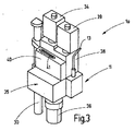
図3は、中央モジュール3に基づいた改良型測定ヘッド1aを示す。この測定ヘッドは図3において付加的なコンポーネントによって完全に隠れている。既に説明した程度でコンポーネントが存在し、同じ参照番号が用いられ、先の説明が参照される。図3において、レンズモジュール26は大きな側面7に取り付けられたレーザー自動焦点モジュール35によって覆われている。そのレーザー36はレンズに対して平行な下向き方向に延在する。図10に示されているように、レーザー36は半透明のミラー37を用いて、場合によってはミラーモジュール16を介してレンズモジュール26の光路に光を射出する。
FIG. 3 shows an
ズームモジュール32の代わりに、中央モジュール3の上側の大きな側面6に階段状のズームモジュール38が設けられ、この階段状ズームモジュールは、半透明のミラーと完全に反射するミラーとを用いて、取り付け位置21から光路を二つの平行な光路に分割する。これら二つの光路のうち一方の光路はカメラモジュール(第一のカメラモジュール)34に至り、他方は補助的なカメラモジュール(第二のカメラモジュール)39に至る。両方のカメラモジュールは段階状のズームモジュール38の上側の面で互いに平行に配置されている。二つのカメラモジュール34,39は好ましくは、異なるチップサイズ及び/又は異なるピクセル数の電子ピクセル型カメラである。それらは同時に作動し、それゆえ同時に画像信号を生成し、その結果、二つのカメラモジュール34,39間で電子的に素早い選択をすることが可能で、それゆえ拡大を切り換え、画像信号も平行して記録することが可能である。補足的な開示のために、DE19514498A1が参照される。
Instead of the
更に、段階状のズームモジュール38はコネクタ41を備えた電気接続モジュール40を支持していてもよい。好ましくは、このコネクタはマルチピンコネクタで、これを用いて例えば環状の照明モジュール28のLED群を作動させるために、電力が測定ヘッド1aに供給可能である。更に、段階状ズームモジュール38の代わりにズームモジュール32が設けられるならば、ズームモジュール32の駆動はコネクタ41を介して制御可能である。接続モジュール40から他のアセンブリに電気信号を送るために、中央モジュール3は図2から明らかなように、その後ろの側面9で、例えば平坦な溝部として形作られたケーブルチャネル42を備える。
Further, the step-
図4は、測定ヘッド1bを提供するための、モジュールの別の組み合わせを示す。既に記載されたモジュールと要素が用いられ、既に述べられた参照番号が参照される程度まで、先の記載が参照される。固定焦点距離を有したレンズ26aが用いられている。中央モジュール3はその前側でカバープレート43を備えている。カバープレートは取り付け位置24と取り付け位置若しくは検査開口若しくはクリーニング開口23とを覆う。
FIG. 4 shows another combination of modules for providing the measuring
図5は、図1に係る測定ヘッド1を示す別の斜視図である。
図6は、図4の実施形態に基づくズームのない異形デザインの光学系測定ヘッド1cを示す。カメラモジュール34が固定レンズ26bに直接取り付けられている。中間モジュール44がカメラモジュール34と中央モジュール3の間に配されており、この中間モジュール44は調整可能な光学コンポーネントを含まず、あるいは光学コンポーネントを全く含まない。これ以外、先の記載が相応して当て嵌まる。
FIG. 5 is another perspective view showing the measuring
FIG. 6 shows an
図7は他の変更例を示す。前側にカバープレート43を備えた中央モジュール3にピエゾ調整モジュール45が取り付けられている。中央モジュールは、その取り付け位置25で、光学干渉レンズ26c、例えばミラウレンズ(Mirau lens)を支持する。上記ピエゾ調整モジュールは例えば50ナノメートルのステップ幅と1秒当たり50ステップの割合で例えばレンズ26を調整するように配されている。(レンズ系の)レンズの能動的な動きがピエゾ調整モジュール45を用いて達成可能である。この測定ヘッド1dを用いて高い測定精度が達成可能である。
FIG. 7 shows another modification. A
図8は、画像結像のみならず光学干渉画像の同時記録のために用いられ得る測定ヘッド1eを示す。既に記載されたコンポーネントが用いられる限り、先の記載が参照される。モジュール式測定システムの使用で、DE 102004022341 A1にしたがう測定構造を履行することが可能である。 FIG. 8 shows a measuring head 1e that can be used for simultaneous recording of optical interference images as well as image formation. As long as the components already described are used, reference is made to the previous description. With the use of a modular measuring system, it is possible to implement a measuring structure according to DE 102004022341 A1.
チューブ46を介して、ビームスプリッタハウジング47はその下側取り付け位置25に取り付けられ、それによって基準ミラー48を備えた基準光路が上記ビームスプリッタハウジングから分岐する。反対側に白色照明ユニット49が配され、それによって上記照明ユニットが光波導体50を介して光を供給可能である。更に上記ユニットは偏波フィルターを含んでいてもよい。λ/4プレートが基準光路に配されていてもよい。或る偏向を示す光を第一のカメラモジュール34に案内し、他の偏向を示す光を第二のカメラモジュール39に案内するために、複数の偏波フィルターが中間モジュール44に設けられてもよい。このようにして、一つの基準画像が或るカメラモジュールで記録され、検査対象のライブ画像が他のカメラモジュールで記録され得る。二つのカメラモジュール34,39は、一方で複数の基準画像を記録して、それらの差がライブ画像を生成するのに用いられ、他方で異なる画像を記録するのに用いられ得る。
Via the
図9は、測定ヘッド1dの形態における既述のモジュールの他の組み合わせを示す。このことを考慮して、レンズ26は取り付け片27に取り付けられ、環状の光モジュール28は側方の取り付け位置15に取り付けられる。下側の取り付け位置25はカバープレートによって閉じられている。
FIG. 9 shows another combination of the modules already described in the form of a measuring head 1d. In consideration of this, the
図10は、選び得るアセンブリ組み合わせの随意選択を図解する既述した多数のモジュールと要素を示す。中央モジュール3のリア側(側面9)は、好ましくは大きな開口を有さず、それゆえ他のモジュールのための取り付けがもたらされない。上記リア側は、例えば測定機械のようなガイド要素に対する中央モジュール3の取り付けのために用いられる。取り付けのために、中央モジュールを機械支持部に機械的に据え付けるための据付装置53を蟻溝52と共に形成する蟻ほぞ状金属シート51を用いることが可能である。好ましくは、蟻溝は矩形の大きな側面9、短いエッジに平行な中央に設けられる。
FIG. 10 shows a number of the modules and elements described above that illustrate the optional choice of assembly combinations that can be selected. The rear side (side 9) of the
六つの側面4,5,6,7,8,9を有した平行六面体の形状をした少なくとも中央モジュール3を備えて構成されるモジュール式測定ヘッドシステム2が提案されている。中央モジュールは内部空間を取り囲み、少なくとも五つの側面4,5,6,7,8で取り付け位置10,15,21,24,25を有し、各々の取り付け位置は、上記内部空間に通じる少なくとも一つの開口の範囲を定めている。付加的な複数のモジュールと共に、中央モジュール3は、非常に多様な光学系測定ヘッドを創出するモジュール式構造キットを形成する。それらのモジュールは照明モジュール11及び/又はレンズモジュール26及び/又はミラーモジュール16及び/又はカメラモジュール34である。これらオプションモジュールの各々は、取り付け位置10,15,21,24,25の少なくとも一つに(任意に他のモジュールを介在させることによって)少なくとも間接的に取り付けられることが可能である。
There has been proposed a modular measuring head system 2 comprising at least a
1 測定ヘッド
2 モジュール式測定ヘッドシステム
3 中央モジュール
4,5 小さな側面
6,7,8,9 大きな側面
10 取り付け位置
11 照明モジュール
12 ハウジング
13 光伝播ケーブル
14 管状延長部
15 取り付け位置
16 ミラーモジュール
17 ミラー
18 中間リング
19 ディスク
20 表面
21 取り付け位置
22 開口
23 取り付け位置/クリーニング開口
24,25 取り付け位置
26 レンズモジュール
27 取り付け片
28 環状照明モジュール
29 保持モジュール
30 保持管
31 フィーラ
32 ズームモジュール
33 管
34 カメラモジュール
35 レーザー自動焦点モジュール
36 レーザー
37 ミラー
38 階段状ズームモジュール
39 カメラモジュール
40 接続モジュール
41 コネクタ
42 ケーブルチャネル
43 カバープレート
44 中間モジュール
45 ピエゾ調整モジュール
46 管
47 ビームスプリッタハウジング
48 基準ミラー
49 照明ユニット
50 光波導体
51 蟻ほぞ金属シート
52 蟻溝
53 装着装置
DESCRIPTION OF
Claims (15)
六つの側面(4,5,6,7,8,9)を有し、内部空間を取り囲み、少なくとも五つの前記側面(4,5,6,7,8)において、少なくとも一つの前記内部空間に通じる開口をそれぞれ取り囲む取り付け位置(10,15,21,24,25)を有する、平行六面体形状の中央モジュール(3)と、
前記取り付け位置(10,15,21,24,25)の少なくとも一つに取り付け可能である照明モジュール(11)と、
上記取り付け位置(10,15,21,24,25)の少なくとも一つに取り付け可能であるレンズモジュール(26)と、
上記取り付け位置(10,15,21,24,25)の少なくとも一つに取り付け可能であるミラーモジュール(16)と、
上記取り付け位置(10,15,21,24,25)の少なくとも一つに取り付け可能であるカメラモジュール(34)と
を少なくとも備えて構成される測定ヘッドシステムであって、上記中央モジュール(3)は機械的装着装置(53)を備えており、この装着装置を用いて中央モジュール(3)、照明モジュール(11)、レンズモジュール(26)、ミラーモジュール(16)、カメラモジュール(34)のうちの少なくとも二つからできている測定ヘッド(1)が機械支持部に装着可能である、モジュール式測定ヘッドシステム。 Modular measuring head system (2)
Have six sides (4,5,6,7,8,9) surrounds the interior space, at least five said side of (4,5,6,7,8), in at least one of said interior space to have a mounting position (10,15,21,24,25) surrounding the opening to each central module parallelepiped shape (3),
A lighting module (11) attachable to at least one of the mounting positions (10, 15, 21, 24, 25) ;
A lens module (26) attachable to at least one of the attachment positions (10, 15, 21, 24, 25);
A mirror module (16) attachable to at least one of the attachment positions (10, 15, 21, 24, 25);
A measuring head system comprising at least a camera module (34) that can be attached to at least one of the attachment positions (10, 15, 21, 24, 25), wherein the central module (3) A mechanical mounting device (53) is provided. Using this mounting device, the central module (3), the illumination module (11), the lens module (26), the mirror module (16), and the camera module (34). A modular measuring head system in which at least two measuring heads (1) can be mounted on a machine support.
Applications Claiming Priority (3)
| Application Number | Priority Date | Filing Date | Title |
|---|---|---|---|
| DE102007018951A DE102007018951B3 (en) | 2007-04-21 | 2007-04-21 | Modular measuring head system |
| DE102007018951.8 | 2007-04-21 | ||
| PCT/EP2008/002305 WO2008128610A1 (en) | 2007-04-21 | 2008-03-22 | Modular measurement head system |
Publications (3)
| Publication Number | Publication Date |
|---|---|
| JP2010525341A JP2010525341A (en) | 2010-07-22 |
| JP2010525341A5 JP2010525341A5 (en) | 2013-10-10 |
| JP5523305B2 true JP5523305B2 (en) | 2014-06-18 |
Family
ID=39522270
Family Applications (1)
| Application Number | Title | Priority Date | Filing Date |
|---|---|---|---|
| JP2010504479A Active JP5523305B2 (en) | 2007-04-21 | 2008-03-22 | Modular measuring head system |
Country Status (4)
| Country | Link |
|---|---|
| US (1) | US8174684B2 (en) |
| JP (1) | JP5523305B2 (en) |
| DE (1) | DE102007018951B3 (en) |
| WO (1) | WO2008128610A1 (en) |
Families Citing this family (2)
| Publication number | Priority date | Publication date | Assignee | Title |
|---|---|---|---|---|
| DE102007000306B4 (en) * | 2007-05-08 | 2015-07-09 | Werth Messtechnik Gmbh | Coordinate measuring machine |
| CA2901248C (en) | 2013-03-14 | 2022-01-18 | Scott Technologies, Inc. | Sensor assembly |
Family Cites Families (10)
| Publication number | Priority date | Publication date | Assignee | Title |
|---|---|---|---|---|
| DE3806686A1 (en) * | 1988-03-02 | 1989-09-14 | Wegu Messtechnik | MULTICOORDINATE MEASURING AND TESTING DEVICE |
| GB9213159D0 (en) * | 1992-06-22 | 1992-08-05 | British Tech Group | Method of and apparatus for interferometrically inspecting a surface of an object |
| DE4445331C5 (en) * | 1994-12-19 | 2006-07-27 | Mycrona Gesellschaft für innovative Messtechnik mbH | Automatic multi-sensor measuring head for coordinate measuring machines |
| DE19747027A1 (en) * | 1997-04-21 | 1998-10-22 | Wegu Messtechnik | Multiple sensor scan device e.g. for coordinate measuring device |
| DE19810333A1 (en) * | 1998-03-11 | 1999-09-23 | Tilo Klett | Automatic tool positioning arrangement |
| IT1299902B1 (en) * | 1998-03-13 | 2000-04-04 | Marposs Spa | HEAD, EQUIPMENT AND METHOD FOR CHECKING LINEAR DIMENSIONS OF MECHANICAL PARTS. |
| JP3468504B2 (en) * | 1999-06-09 | 2003-11-17 | 株式会社ミツトヨ | Measurement procedure file generation method, measurement device, and storage medium |
| DE20320216U1 (en) * | 2003-12-29 | 2004-03-18 | Iqsun Gmbh | laser scanner |
| DE102005018168C5 (en) * | 2005-04-19 | 2013-11-07 | Carl Mahr Holding Gmbh | White light interferometric microscope measuring device |
| EP2037214A1 (en) * | 2007-09-14 | 2009-03-18 | Leica Geosystems AG | Method and measuring device for measuring surfaces |
-
2007
- 2007-04-21 DE DE102007018951A patent/DE102007018951B3/en active Active
-
2008
- 2008-03-22 JP JP2010504479A patent/JP5523305B2/en active Active
- 2008-03-22 WO PCT/EP2008/002305 patent/WO2008128610A1/en active Application Filing
-
2009
- 2009-10-20 US US12/589,250 patent/US8174684B2/en active Active
Also Published As
| Publication number | Publication date |
|---|---|
| DE102007018951B3 (en) | 2009-01-02 |
| WO2008128610A1 (en) | 2008-10-30 |
| JP2010525341A (en) | 2010-07-22 |
| US8174684B2 (en) | 2012-05-08 |
| US20100157288A1 (en) | 2010-06-24 |
Similar Documents
| Publication | Publication Date | Title |
|---|---|---|
| KR101409644B1 (en) | Three-dimensional shape measuring apparatus | |
| US7400413B2 (en) | Three-dimensional shape measuring apparatus using shadow moire | |
| CN110045386B (en) | Method and system for optical alignment of light detection and ranging | |
| US8599372B2 (en) | Linear chromatic confocal microscopic system | |
| US9042010B2 (en) | Scanning microscope and method for optically scanning one or more samples | |
| US9684149B2 (en) | Coordinate measuring machine and method for determining spatial coordinates on a measurement object | |
| JP6282654B2 (en) | Optical system configuration and optical microscope | |
| CN104054014A (en) | Arrangement for use in the illumination of a specimen in SPIM microscopy | |
| JP2006047958A (en) | Exposure device and exposure method | |
| JP2006522948A (en) | Microscope arrangement | |
| CN107807495B (en) | Pattern exposure apparatus, exposure head, and pattern exposure method | |
| JP5523305B2 (en) | Modular measuring head system | |
| JP2014514779A (en) | Lithographic system for processing at least part of a target | |
| JP4855388B2 (en) | Lens barrel rotating apparatus having at least four positions for light incident on or emitted from a laser scanning microscope | |
| JP2010014837A (en) | Optical scanning microscope | |
| JP5512122B2 (en) | Scanning laser microscope and sub-assembly for non-descanned detection | |
| JPH06347703A (en) | Intermediate connecting lens barrel | |
| US7936502B2 (en) | Microscope | |
| JP7422563B2 (en) | Medical projection devices and medical observation systems | |
| JP2007047043A (en) | Multi-wavelength interferometer | |
| US20040145804A1 (en) | Microscope lens and the use of a microscope lens of this type in a microscope | |
| JP2013145123A (en) | Optical system with wide-angle reflection coaxial illumination | |
| JP6063658B2 (en) | Imaging device | |
| JP2006145849A (en) | Optical device for inspection and inspecting device equipped with the same | |
| JP2011027804A (en) | Confocal microscope |
Legal Events
| Date | Code | Title | Description |
|---|---|---|---|
| A621 | Written request for application examination |
Free format text: JAPANESE INTERMEDIATE CODE: A621 Effective date: 20101126 |
|
| RD04 | Notification of resignation of power of attorney |
Free format text: JAPANESE INTERMEDIATE CODE: A7424 Effective date: 20101228 |
|
| A131 | Notification of reasons for refusal |
Free format text: JAPANESE INTERMEDIATE CODE: A131 Effective date: 20130422 |
|
| A601 | Written request for extension of time |
Free format text: JAPANESE INTERMEDIATE CODE: A601 Effective date: 20130719 |
|
| A602 | Written permission of extension of time |
Free format text: JAPANESE INTERMEDIATE CODE: A602 Effective date: 20130726 |
|
| A524 | Written submission of copy of amendment under article 19 pct |
Free format text: JAPANESE INTERMEDIATE CODE: A524 Effective date: 20130822 |
|
| TRDD | Decision of grant or rejection written | ||
| A01 | Written decision to grant a patent or to grant a registration (utility model) |
Free format text: JAPANESE INTERMEDIATE CODE: A01 Effective date: 20140310 |
|
| A61 | First payment of annual fees (during grant procedure) |
Free format text: JAPANESE INTERMEDIATE CODE: A61 Effective date: 20140408 |
|
| R150 | Certificate of patent or registration of utility model |
Ref document number: 5523305 Country of ref document: JP Free format text: JAPANESE INTERMEDIATE CODE: R150 |
|
| R250 | Receipt of annual fees |
Free format text: JAPANESE INTERMEDIATE CODE: R250 |
|
| R250 | Receipt of annual fees |
Free format text: JAPANESE INTERMEDIATE CODE: R250 |
|
| R250 | Receipt of annual fees |
Free format text: JAPANESE INTERMEDIATE CODE: R250 |
|
| R250 | Receipt of annual fees |
Free format text: JAPANESE INTERMEDIATE CODE: R250 |
|
| R250 | Receipt of annual fees |
Free format text: JAPANESE INTERMEDIATE CODE: R250 |
|
| R250 | Receipt of annual fees |
Free format text: JAPANESE INTERMEDIATE CODE: R250 |
|
| R250 | Receipt of annual fees |
Free format text: JAPANESE INTERMEDIATE CODE: R250 |
|
| R250 | Receipt of annual fees |
Free format text: JAPANESE INTERMEDIATE CODE: R250 |