JP5517183B2 - Game machine - Google Patents

Game machine Download PDF

Info

Publication number
JP5517183B2
JP5517183B2 JP2008211879A JP2008211879A JP5517183B2 JP 5517183 B2 JP5517183 B2 JP 5517183B2 JP 2008211879 A JP2008211879 A JP 2008211879A JP 2008211879 A JP2008211879 A JP 2008211879A JP 5517183 B2 JP5517183 B2 JP 5517183B2
Authority
JP
Japan
Prior art keywords
effect
detection
state
player
holding
Prior art date
Legal status (The legal status is an assumption and is not a legal conclusion. Google has not performed a legal analysis and makes no representation as to the accuracy of the status listed.)
Active
Application number
JP2008211879A
Other languages
Japanese (ja)
Other versions
JP2010046210A (en
Inventor
智也 永江
Current Assignee (The listed assignees may be inaccurate. Google has not performed a legal analysis and makes no representation or warranty as to the accuracy of the list.)
Toyomaru Industry Co Ltd
Original Assignee
Toyomaru Industry Co Ltd
Priority date (The priority date is an assumption and is not a legal conclusion. Google has not performed a legal analysis and makes no representation as to the accuracy of the date listed.)
Filing date
Publication date
Application filed by Toyomaru Industry Co Ltd filed Critical Toyomaru Industry Co Ltd
Priority to JP2008211879A priority Critical patent/JP5517183B2/en
Publication of JP2010046210A publication Critical patent/JP2010046210A/en
Application granted granted Critical
Publication of JP5517183B2 publication Critical patent/JP5517183B2/en
Active legal-status Critical Current
Anticipated expiration legal-status Critical

Links

Images

Landscapes

  • Pinball Game Machines (AREA)
  • Display Devices Of Pinball Game Machines (AREA)

Description

本発明は遊技機に関し、詳細には、遊技者による操作手段の操作に応じて演出内容を変化させることが可能な遊技機に関する。   The present invention relates to a gaming machine, and more particularly, to a gaming machine capable of changing the contents of effects according to the operation of an operating means by a player.

従来、遊技者の興趣を惹き付けるために、様々な演出を行う遊技機が知られている。この遊技機では、特定の始動口を遊技球が通過することを契機として、遊技者に有利な当たり遊技を実行するか否かの判定である当たり判定が行われる。そして、画像を表示する表示手段や音声を発生させるスピーカ等の演出手段が設けられており、当たり判定の結果を遊技者に報知する報知演出や、当たり遊技中の演出等の様々な演出が演出手段によって実行される。しかし、これらの演出はあらかじめ決められたパターンに従って実行されており、演出が単調なものとなっていた。また、遊技に積極的に参加している印象を遊技者に与えることもできなかった。   2. Description of the Related Art Conventionally, gaming machines that perform various effects are known to attract the interest of players. In this gaming machine, a hit determination, which is a determination as to whether or not a hit game advantageous to the player is executed, is triggered by the passing of a game ball through a specific starting port. Further, there are provided presentation means such as a display means for displaying an image and a speaker for generating sound, and various effects such as a notification effect for notifying the player of the result of the hit determination and an effect during the hit game are produced. Executed by means. However, these effects are executed according to a predetermined pattern, and the effects are monotonous. Also, the player could not give an impression of being actively participating in the game.

そこで、遊技者が操作可能な操作手段を設け、操作手段の操作に応じて演出内容を変化させる遊技機が提案されている(例えば、特許文献1参照)。この遊技機で遊技を行っている遊技者は、操作手段を操作することによって、複数の演出の中から所望する演出を選択して実行させることができる。よって、演出が単調となることを防止して遊技者を楽しませることができる。   In view of this, there has been proposed a gaming machine that is provided with operating means that can be operated by the player and that changes the contents of the effect according to the operation of the operating means (see, for example, Patent Document 1). A player playing a game on this gaming machine can select and execute a desired effect from a plurality of effects by operating the operation means. Therefore, the player can be entertained by preventing the production from becoming monotonous.

また、操作手段が操作されるタイミングに応じて異なる演出を実行する遊技機も提案されている(例えば、特許文献2参照)。この遊技機は、操作手段が操作されたタイミングが所定のタイミングであれば、当たりを示す演出を行う。一方で、操作タイミングが所定のタイミングでなければ、はずれを示す演出を行う。そして、実行された演出と当たり判定の結果とが異なる場合には、演出が示す結果を当たり判定の結果に合致させるための特定の演出を付加する。これにより、自己の技量により当たり遊技が実行されるように遊技者に認識させて、遊技者の興趣を惹き付けている。
特開2003−199904号公報 特開2005−87769号公報
In addition, a gaming machine that executes different effects according to the timing at which the operating means is operated has been proposed (see, for example, Patent Document 2). If the timing at which the operating means is operated is a predetermined timing, this gaming machine performs an effect indicating a win. On the other hand, if the operation timing is not a predetermined timing, an effect indicating a deviation is performed. If the executed effect is different from the result of the hit determination, a specific effect is added to match the result indicated by the effect with the result of the hit determination. Thereby, the player is made to recognize that the winning game is executed according to his / her skill, and the player's interest is attracted.
JP 2003-199904 A Japanese Patent Laid-Open No. 2005-87769

しかしながら、このような従来の遊技機では、遊技者は操作手段の操作が面倒である場合でも、所望する演出を実行させるためには操作手段を操作しなければならないという問題点があった。また、特に、操作手段を短時間の間に断続的に操作すると特別な演出が実行される場合には、断続的に操作する行為を恥ずかしく思う遊技者も多く、操作手段を操作することなく特別な演出を楽しみたいという遊技者の要望に応えることはできなかった。   However, in such a conventional gaming machine, there is a problem that the player has to operate the operation means in order to execute a desired effect even when the operation of the operation means is troublesome. In particular, when a special performance is performed when the operation means is intermittently operated for a short time, many players feel embarrassed to perform the intermittent operation, and the special operation is not performed without operating the operation means. It was not possible to meet the player's request to enjoy a special performance.

本発明は上記課題を解決するためになされたものであり、操作手段を操作することによって実行される特別な演出を、操作手段を操作することなく楽しみたいという遊技者の要望に応えることができる遊技機を提供することを目的とする。   The present invention has been made to solve the above-described problems, and can meet a player's desire to enjoy a special performance executed by operating the operating means without operating the operating means. An object is to provide a gaming machine.

上記目的を達成するために、請求項1に記載の遊技機は、演出を実行する演出実行手段と、初期位置と終点位置との間を移動する操作部と、当該操作部が前記初期位置から前記初期位置と前記終点位置との間の所定位置まで移動されたことを検出する操作検出手段と、前記操作部を前記初期位置へ向けて付勢する付勢手段と、前記所定位置よりも前記終点位置側へ前記操作部が移動された場合に、前記所定位置又は当該所定位置よりも前記終点位置側で前記操作部を保持する保持手段と、前記保持手段によって前記操作部が保持されていることを検出する保持検出手段と、前記保持手段による保持を解除する保持解除手段とを備え、遊技者が操作可能な操作手段と、前記操作検出手段による検出結果に応じて、前記演出実行手段による演出の実行を制御する演出実行制御手段と、前記保持検出手段によって前記操作部が保持されていることが検出されている間、前記操作部が前記初期位置から前記所定位置まで移動されたことが前記操作検出手段によって検出されている状態である操作恒常検出状態を設定する操作恒常検出状態設定手段と、前記保持解除手段によって前記保持手段による保持が解除された場合に、前記操作恒常検出状態設定手段による前記操作恒常検出状態の設定を解除する操作恒常検出状態解除手段と、前記操作恒常検出状態設定手段によって前記操作恒常検出状態が設定されている場合に、所定時間当たりに複数回断続して前記操作部が前記初期位置から前記所定位置まで移動される場合の前記操作検出手段による検出結果を、前記演出実行制御手段が用いる検出結果として生成する断続操作結果生成手段と、遊技盤に設けられた始動口に遊技球が入賞することを契機として、遊技者に有利な遊技状態である有利状態を生起するか否かを判定する判定手段と、前記判定手段による判定の結果に基づいて、前記有利状態が生起される期待度を遊技者に報知する演出である報知演出を、前記演出実行手段に実行させる報知演出実行制御手段と、前記操作有効期間中における前記操作検出手段による検出回数を累計した回数である累計操作回数を記憶する累計操作回数記憶手段とを備え、前記操作検出手段は、前記操作恒常検出状態設定手段によって前記操作恒常検出状態が設定されていない場合、前記操作部が前記初期位置から前記所定位置まで移動されたことを検出可能であり、前記報知演出実行制御手段は、前記累計操作回数記憶手段に記憶された前記累計操作回数が大きいほど、前記期待度の高い前記報知演出を実行可能であり、前記断続操作結果生成手段は、前記操作恒常検出状態が設定されている場合に生成する所定時間当たりの断続検出回数を、1秒間当たり6回以下とすることを特徴とする。 In order to achieve the above object, the gaming machine according to claim 1 includes an effect execution means for executing an effect, an operation unit that moves between an initial position and an end point position, and the operation unit from the initial position. Operation detecting means for detecting movement to a predetermined position between the initial position and the end position, urging means for urging the operation portion toward the initial position, and When the operation unit is moved to the end position side, the operation unit is held by the predetermined position or a holding unit that holds the operation unit at the end point side of the predetermined position, and the holding unit holds the operation unit. A holding detecting means for detecting this, and a holding releasing means for releasing the holding by the holding means, and an operation means that can be operated by the player, and according to a detection result by the operation detecting means, by the effect executing means Directing It is detected that the operation unit is moved from the initial position to the predetermined position while it is detected that the operation unit is held by the production execution control unit that controls the line and the holding detection unit. An operation constant detection state setting unit that sets an operation constant detection state that is a state detected by the detection unit, and when the holding by the holding unit is released by the holding release unit, the operation constant detection state setting unit When the operation constant detection state is set by the operation constant detection state release means and the operation constant detection state setting means for canceling the setting of the operation constant detection state, the operation is intermittently performed a plurality of times per predetermined time. The effect execution control means uses the detection result by the operation detection means when the section is moved from the initial position to the predetermined position. Determining the intermittent operation result generation means for generating as a result, in response to winning game ball to the starting opening provided on the game board, whether arising advantageous condition that is advantageous gaming state to the player out And a notification effect execution control unit that causes the effect execution unit to execute a notification effect that is an effect of notifying the player of the expected degree of occurrence of the advantageous state based on a result of determination by the determination unit. And a cumulative operation count storage means for storing a cumulative operation count that is a cumulative count of the number of detections by the operation detection means during the operation valid period , wherein the operation detection means is controlled by the operation constant detection state setting means. If the operation homeostasis detection state is not set, detectable der is, the notification effect execution control hand in that the operating part is moved from the initial position to the predetermined position The higher the cumulative operation count stored in the cumulative operation count storage means, the higher the expected degree of the notification effect can be executed, and the intermittent operation result generation means sets the operation constant detection state. intermittent detection count per a predetermined time to produce if they are to be characterized to Rukoto and below 6 times per second.

また、本発明の請求項に記載の遊技機は、請求項1に記載の発明の構成に加え、前記操作恒常検出状態設定手段によって前記操作恒常検出状態が設定されている間に、前記演出実行手段によって所定の演出が実行される場合、前記操作恒常検出状態の解除を遊技者に促す解除指示手段を備えている。 Further, in the gaming machine according to claim 2 of the present invention, in addition to the configuration of the invention according to claim 1, while the operation constant detection state is set by the operation constant detection state setting means, the effect When a predetermined effect is executed by the execution means, a release instructing means for prompting the player to release the operation constant detection state is provided.

また、本発明の請求項に記載の遊技機は、請求項1又は2に記載の発明の構成に加え、前記操作手段の操作を有効とする操作有効期間を設定する有効期間設定手段と、当該有効期間設定手段によって設定された前記操作有効期間中に前記操作手段の操作を有効とする有効制御手段と、当該有効制御手段によって前記操作手段の操作が有効とされていることを遊技者に報知する操作有効報知手段とを備え、前記操作検出手段による検出結果に応じて制御される演出には、前記操作有効報知手段による報知を伴う演出と、前記操作有効報知手段による報知を伴わない演出とが設けられていることを特徴とする Further, the gaming machine according to claim 3 of the present invention, in addition to the configuration of the invention according to claim 1 or 2 , effective period setting means for setting an operation effective period for validating the operation of the operation means, The effective control means for validating the operation of the operation means during the operation valid period set by the valid period setting means, and the player that the operation of the operation means is validated by the effective control means. The effect that is provided with the notification of the operation validity notifying unit and the effect that is not accompanied by the notification of the operation validity notifying unit are included in the effect that is provided according to the detection result by the operation detecting unit. And is provided .

請求項1に記載の遊技機によると、遊技者が操作可能な操作手段を備えており、操作手段が操作されることに応じて演出の実行を制御することができる。そして、操作手段が操作されたことが検出されている状態である操作恒常検出状態を設定する操作恒常検出状態設定手段、及びこれを解除する操作恒常検出状態解除手段を備えている。従って、遊技者は、操作恒常検出状態を設定することで、操作手段の操作が面倒な場合や恥ずかしい場合、さらには、操作のタイミングが分からない場合や操作を忘れていた場合でも、実際に操作を行うことなく、操作手段を操作した場合に実行される演出を楽しむことができる。また、操作恒常検出状態の設定を解除することで、遊技者は操作手段を操作するか否かを自ら選択でき、所望の演出を楽しむことができる。また、操作手段の操作部が初期位置へ向けて付勢されており、この操作部が所定位置まで移動されることで、操作を検出することができる。さらに、所定位置よりも終点位置側へ移動された場合に、操作部を保持し、操作恒常検出状態を設定することができる。これにより、1つの操作手段で、遊技者による操作を検出することもでき、操作恒常検出状態を設定することもできる。よって、部品点数を削減することができ、操作方法も単純となる。また、遊技者は、操作部が移動された状態で保持されているか否かを見るだけで、操作恒常検出状態が設定されているか否かを容易に把握することができる。また、操作恒常検出状態が設定されている場合に、操作手段が所定時間内に複数回断続して操作される場合と同じ演出を演出実行手段によって実行することができる。従って、遊技者は、操作手段を断続的に操作することが面倒である場合や恥ずかしい場合でも、断続的に操作した場合に実行される演出を楽しむことができる。
また、操作恒常検出状態が設定されている場合、断続操作結果生成手段によって生成される断続検出回数は、1秒間当たり6回以下である。従って、遊技者は、操作恒常検出状態の設定を解除して、自ら操作手段を操作すれば、1秒間当たり6回よりも多くの回数操作手段を操作し得る。よって、操作恒常検出状態を設定して、操作手段を操作することなく演出を楽しむか、操作恒常検出状態を設定せずに、より多くの回数操作手段を操作して演出を楽しむかを、遊技者に選択させることができる。
また、操作有効期間中における操作検出手段による検出回数を累計する累計操作回数記憶手段を備え、累計操作回数が大きいほど期待度の高い報知演出を実行する。従って、遊技者は所望の演出を楽しむことができる。
According to the gaming machine of the first aspect, the operation means that can be operated by the player is provided, and the execution of the effect can be controlled in response to the operation means being operated. And the operation constant detection state setting means which sets the operation constant detection state which is the state in which it is detected that the operation means was operated, and the operation constant detection state cancellation | release means which cancel | releases this are provided. Therefore, by setting the operation constant detection state, the player can actually operate even when the operation of the operation means is troublesome or embarrassed, or even when the timing of the operation is unknown or the operation is forgotten. It is possible to enjoy the effect executed when the operating means is operated without performing the above. Further, by canceling the setting of the operation constant detection state, the player can select whether or not to operate the operation means, and can enjoy a desired effect. Further, the operation part of the operation means is biased toward the initial position, and the operation can be detected by moving the operation part to a predetermined position. Furthermore, when it moves to the end position side from the predetermined position, the operation unit can be held and the operation constant detection state can be set. Thereby, the operation by the player can be detected by one operation means, and the operation constant detection state can be set. Therefore, the number of parts can be reduced and the operation method is simplified. Further, the player can easily grasp whether or not the operation constant detection state is set only by looking at whether or not the operation unit is held in a moved state. Further, when the operation constant detection state is set, the same effect as when the operation unit is operated intermittently a plurality of times within a predetermined time can be executed by the effect execution unit. Therefore, even when it is troublesome or embarrassed to operate the operation means intermittently, the player can enjoy the effects that are executed when the operation is operated intermittently.
When the operation constant detection state is set, the number of intermittent detections generated by the intermittent operation result generation unit is six or less per second. Therefore, the player can operate the operation means more than 6 times per second by canceling the setting of the operation constant detection state and operating the operation means by himself / herself. Therefore, whether to enjoy the production without setting the operation constant detection state and operating the operation means, or whether to enjoy the production by operating the operation means more times without setting the operation constant detection state. Can be selected.
In addition, a cumulative operation number storage unit that accumulates the number of detections by the operation detection unit during the operation valid period is provided, and a notification effect with a higher expectation is executed as the cumulative operation number increases. Therefore, the player can enjoy a desired effect.

また、本発明の請求項に記載の遊技機は、請求項1に記載の発明の効果に加え、例えば操作手段が操作されるタイミングに応じて内容が変化する演出等、所定の演出を行う場合に、操作恒常検出状態の解除を遊技者に促すことができる。従って、遊技者は、実行される演出の種類に応じて、操作恒常検出状態の設定及び解除を適切に行うことができる。 In addition to the effect of the invention according to claim 1, the gaming machine according to claim 2 of the present invention performs a predetermined effect such as an effect in which the content changes according to the timing at which the operating means is operated. In this case, the player can be prompted to release the operation constant detection state. Therefore, the player can appropriately set and cancel the operation constant detection state according to the type of effect to be executed.

また、本発明の請求項に記載の遊技機は、請求項1又は2に記載の発明の効果に加え、操作手段の操作が有効とされていることを遊技者に報知する操作有効報知手段を備える一方で、操作手段の操作に応じて制御される演出には、操作有効報知手段による報知を伴わない、所謂隠し演出が設けられている。従って、遊技者は、操作恒常検出状態を設定すれば、隠し演出が実行されるタイミングが分からない場合でも隠し演出を楽しむことができる。また、操作恒常検出状態を解除すれば、隠し演出が行われることを期待しながら、操作手段を操作して遊技を楽しむことができる。 In addition to the effects of the invention described in claim 1 or 2 , the gaming machine according to claim 3 of the present invention is an operation validity notifying means for notifying the player that the operation of the operation means is valid. On the other hand, the effect controlled according to the operation of the operation means is provided with a so-called hidden effect that is not accompanied by notification by the operation validity notification means. Therefore, if the player sets the operation constant detection state, the player can enjoy the hidden effect even when the timing at which the hidden effect is executed is not known. Further, if the operation constant detection state is canceled, it is possible to enjoy the game by operating the operation means while expecting a hidden effect.

以下、本発明に係る遊技機の一実施の形態であるパチンコ機1について、図面を参照して説明する。まず、図1及び図2を参照して、パチンコ機1の機械的構成について説明する。図1は、パチンコ機1の正面図であり、図2は、遊技盤2の正面図である。   Hereinafter, a pachinko machine 1 which is an embodiment of a gaming machine according to the present invention will be described with reference to the drawings. First, with reference to FIG.1 and FIG.2, the mechanical structure of the pachinko machine 1 is demonstrated. FIG. 1 is a front view of the pachinko machine 1, and FIG. 2 is a front view of the game board 2.

図1に示すように、パチンコ機1の上半分の部分には、発射ハンドル7の操作により図示外の発射機から発射された遊技媒体としての遊技球が流下する遊技盤2が設けられている。この遊技盤2は略正方形であり(図2参照)、透明なガラス板を保持した前面枠13で保護されている。遊技盤2の下方部には、発射機に遊技球を供給し、且つ賞品球を受ける上皿5が設けられており、上皿5の中央には、遊技者によって操作される操作ボタン20が配設されている。そして、上皿5の直下には、賞品球を受ける下皿6が設けられ、下皿6の右横には、遊技球の発射を調整する発射ハンドル7が設けられている。さらに、前面枠13の上部の左右の角にはスピーカ48がそれぞれ設けられており、前面枠13の前面には演出用の電飾ランプが多数設けられている。   As shown in FIG. 1, in the upper half of the pachinko machine 1, a game board 2 is provided in which a game ball as a game medium launched from a launcher (not shown) by the operation of the launch handle 7 flows down. . The game board 2 is substantially square (see FIG. 2), and is protected by a front frame 13 holding a transparent glass plate. An upper plate 5 is provided below the game board 2 to supply game balls to the launcher and receive prize balls. An operation button 20 operated by a player is provided at the center of the upper plate 5. It is arranged. A lower plate 6 for receiving a prize ball is provided directly below the upper plate 5, and a launch handle 7 for adjusting the launch of the game ball is provided on the right side of the lower plate 6. Furthermore, speakers 48 are respectively provided at the left and right corners of the upper portion of the front frame 13, and a large number of lighting lamps for production are provided on the front surface of the front frame 13.

また、図2に示すように、遊技盤2の前面にはガイドレール3で囲まれた略円形の遊技領域4が設けられている。この遊技領域4の略中央には、表示画面28や役物装置30等を備えた図柄表示装置8が配設されている。そして、図柄表示装置8の左方には普通図柄始動ゲート12が設けられており、図柄表示装置8の下方には特別図柄始動電動役物15が、さらにその直下には第一大入賞口16が配設されている。また、図柄表示装置8の上部には第二大入賞口17が配設されており、普通図柄始動ゲート12の下方には、大当たり判定の結果を示す特別図柄や普通当たり判定の結果を示す普通図柄、及び各種保留球数を表示する図柄表示部11が設けられている。尚、保留球数とは、普通図柄始動ゲート12又は特別図柄始動電動役物15を通過した遊技球のうち、未だ当たり判定が行われていない遊技球の数である。また、第一大入賞口16は、遊技者に多数の遊技球が払い出される15ラウンド大当たり遊技中に開放され、第二大入賞口17は、15ラウンド大当たり遊技よりも払い出される遊技球が少ない2ラウンド大当たり遊技及び小当たり遊技中に開放される。   As shown in FIG. 2, a substantially circular game area 4 surrounded by a guide rail 3 is provided on the front surface of the game board 2. A symbol display device 8 having a display screen 28, an accessory device 30 and the like is disposed in the approximate center of the game area 4. An ordinary symbol start gate 12 is provided on the left side of the symbol display device 8, a special symbol start electric accessory 15 is provided below the symbol display device 8, and a first big prize opening 16 is provided immediately below. Is arranged. A second big prize opening 17 is arranged at the upper part of the symbol display device 8, and below the normal symbol starting gate 12, a special symbol indicating the result of the jackpot determination and a normal symbol indicating the result of the normal hit determination are shown. A symbol display unit 11 for displaying symbols and various numbers of reserved balls is provided. Note that the number of reserved balls is the number of game balls that have not yet been determined to hit among the game balls that have passed through the normal symbol start gate 12 or the special symbol start electric accessory 15. The first grand prize opening 16 is opened during a 15-round jackpot game in which a large number of game balls are paid out to the player, and the second big prize opening 17 has less game balls to be paid out than the 15 round jackpot game 2 Open during round jackpot and small hit games.

次いで、図柄表示装置8について説明する。図柄表示装置8の左端には、図柄表示装置8の外側から内側へ遊技球を案内する案内路18が設けられており、案内路18によって案内された遊技球は、可動部材19の右部へ落下する。可動部材19は、竹製のししおどしをかたどって合成樹脂により形成されており、重心よりもやや右側を回転中心として、所定範囲を回転可能に支持されている。そして、通常は右部が上方に傾いた状態で静止しているが、案内路18によって案内された遊技球が右部へ落下すると、遊技球の重さによって可動部材19の右部は下方へ傾き、遊技球を図柄表示装置8の中央へ向けて排出する。これにより、案内路18によって案内された遊技球が特別図柄始動電動役物15へ入賞する割合を高めつつ、遊技球を利用して可動部材19を動作させて、遊技者を楽しませることができる。   Next, the symbol display device 8 will be described. A guide path 18 is provided at the left end of the symbol display device 8 to guide the game ball from the outside to the inside of the symbol display device 8. The game ball guided by the guide path 18 moves to the right part of the movable member 19. Fall. The movable member 19 is formed of a synthetic resin in the shape of a bamboo squeeze, and is supported so as to be rotatable within a predetermined range with the right side of the center of gravity as the center of rotation. Normally, the right part is stationary with the upper part tilted upward, but when the game ball guided by the guide path 18 falls to the right part, the right part of the movable member 19 moves downward due to the weight of the game ball. The game ball is tilted and discharged toward the center of the symbol display device 8. Thereby, while increasing the rate at which the game ball guided by the guide path 18 wins the special symbol starting electric accessory 15, the movable member 19 can be operated using the game ball to entertain the player. .

また、図柄表示装置8の右側には、役物装置30が配設されている。役物装置30の基体は、合成樹脂により茶筅の形状に形成されており、上部を中心として揺動可能に支持されている。また、図示しないが、基体の内側には、第二大入賞口17へ入賞した遊技球を停留させる停留部と、停留部に停留していた遊技球をクルーン34へ誘導する誘導路とが設けられている。そして、基体を振動させるためのモータと、停留部による遊技球の停留を解除するソレノイドとが配設されており、これらを制御することで、基体を振動させる演出、及び遊技球をクルーン34へ排出する演出を実行することができる。また、クルーン34には、遊技球が入球する入球孔が3つ形成されており、いずれの入球孔に遊技球が入球するかに応じて、演出の態様を決定するための所謂モードが振り分けられる。   An accessory device 30 is disposed on the right side of the symbol display device 8. The base of the accessory device 30 is formed in a teacup shape from a synthetic resin, and is supported so as to be swingable around the upper part. Although not shown, a stopping part for stopping the game ball won in the second grand prize opening 17 and a guide way for guiding the game ball stopped in the stopping part to the croon 34 are provided inside the base. It has been. A motor for vibrating the base and a solenoid for releasing the stop of the game ball by the stop are disposed. By controlling these, an effect for vibrating the base and the game ball to the clown 34 are provided. An effect of discharging can be executed. In addition, the Kleon 34 is formed with three entrance holes into which game balls enter, so-called so-called for determining the mode of production according to which entrance hole the game balls enter. Modes are sorted.

そして、図柄表示装置8の中央には、LCDからなる表示画面28が配設されている。この表示画面28には、動画やメッセージ等様々な映像が表示される。特に、大当たり判定の結果を示す3つのデモ図柄が画面中央に表示される。そして、判定結果を遊技者に報知するための演出である報知演出が開始されると、特別図柄の変動に同期してデモ図柄が変動を開始し、高速変動を経て低速変動となり、左、右の順で停止する。そして、左右のデモ図柄が同一の図柄となれば、判定結果が大当たりの可能性があることを示す様々なリーチ演出が行われて、全てのデモ図柄が同一となれば、大当たり遊技が開始されることとなる。一方で、低速変動後に停止した左右のデモ図柄が異なる図柄であれば、リーチ演出が行われることなくそのまま中央のデモ図柄も停止し、判定結果がはずれであることが示される。   In the center of the symbol display device 8, a display screen 28 composed of an LCD is disposed. On this display screen 28, various images such as moving images and messages are displayed. In particular, three demo symbols indicating the result of jackpot determination are displayed in the center of the screen. When the notification effect, which is an effect for notifying the determination result to the player, is started, the demo symbol starts to fluctuate in synchronization with the fluctuation of the special symbol. Stop in this order. Then, if the left and right demo symbols are the same, various reach effects are performed indicating that the judgment result may be a big hit. If all the demo symbols are the same, the big hit game is started. The Rukoto. On the other hand, if the left and right demo symbols that have stopped after the low-speed fluctuation are different, the center demo symbol is also stopped without performing the reach effect, indicating that the determination result is off.

次に、図3及び図4を参照して、操作ボタン20について説明する。図3は、オート状態解除中の操作ボタン20の部分断面図であり、図4は、オート状態設定中の操作ボタン20の部分断面図である。尚、オート状態とは、常に又は断続的にボタンが押下されている状態(本発明における「操作恒常検出状態」)である。操作ボタン20は、主に基部90、柱部93、及び操作部96により構成されている。   Next, the operation button 20 will be described with reference to FIGS. 3 and 4. FIG. 3 is a partial cross-sectional view of the operation button 20 during cancellation of the auto state, and FIG. 4 is a partial cross-sectional view of the operation button 20 during setting of the auto state. The auto state is a state in which the button is pressed constantly or intermittently (“operation constant detection state” in the present invention). The operation button 20 is mainly composed of a base 90, a pillar 93, and an operation unit 96.

基部90は、円柱状の凹部91を備え、この凹部91において柱部93及び操作部96を上下方向に移動可能に支持する。また、凹部91の上端部には、内側へ延びるフランジ92が形成されており、柱部93及び操作部96が凹部91から抜け出ることを防止している。   The base 90 includes a cylindrical recess 91, and supports the column portion 93 and the operation portion 96 in the recess 91 so as to be movable in the vertical direction. Further, a flange 92 extending inward is formed at the upper end portion of the concave portion 91 to prevent the column portion 93 and the operation portion 96 from coming out of the concave portion 91.

柱部93は円柱形状であり、凹部91に収納されている。そして、柱部93の底部と凹部91の底面との間には第一バネ101が配設されており、柱部93はこの第一バネ101によって上方に付勢されている。さらに、柱部93の底部、及び凹部91の底面のそれぞれには、柱部93が下方へ押し込まれたことを互いに接触することによって検出する押し込み検出スイッチ98が設けられている。また、柱部93の上端部から上方へコの字状の係合部94が延びており、操作部96の下部に設けられた被係合部100に係合することで、柱部93と操作部96との距離を制限している。   The column part 93 has a cylindrical shape and is accommodated in the recess 91. A first spring 101 is disposed between the bottom of the pillar portion 93 and the bottom surface of the recess 91, and the pillar portion 93 is biased upward by the first spring 101. Further, a push-in detection switch 98 is provided on each of the bottom part of the pillar part 93 and the bottom face of the concave part 91 to detect that the pillar part 93 is pushed downward by contacting each other. Further, a U-shaped engaging portion 94 extends upward from the upper end portion of the pillar portion 93, and is engaged with the engaged portion 100 provided at the lower portion of the operation portion 96, thereby The distance from the operation unit 96 is limited.

操作部96は、光透過性を有する合成樹脂によって略円筒状に形成された中空部材であり、凹部91における柱部93の上方で上下動可能に支持されている。そして、操作部96の底部と柱部93の上部との間には第二バネ102が配設されており、操作部96は第二バネ102によって上方に付勢されている。また、操作部96の内部には操作有効報知LED97が設けられており、操作ボタン20の操作が有効となっていることを、操作有効報知LED97を点灯させることで遊技者に報知することができる。さらに、操作部96の底部、及び柱部93の上部のそれぞれには、操作部96が押下されたことを検出する押下検出スイッチ99が設けられている。   The operation part 96 is a hollow member formed in a substantially cylindrical shape with a light-transmitting synthetic resin, and is supported above the column part 93 in the recess 91 so as to be movable up and down. A second spring 102 is disposed between the bottom of the operation unit 96 and the upper portion of the column part 93, and the operation unit 96 is urged upward by the second spring 102. Further, an operation validity notification LED 97 is provided inside the operation unit 96, and the player can be notified that the operation of the operation button 20 is enabled by turning on the operation validity notification LED 97. . Further, a press detection switch 99 for detecting that the operation unit 96 is pressed is provided on each of the bottom of the operation unit 96 and the upper part of the column part 93.

ここで、操作ボタン20の保持・解除機構について説明する。柱部93の側面には、操作ボタン20の押し込み状態での保持、及び保持解除を行うための第一〜第五ガイド溝105〜109が形成されている。第一ガイド溝105は左斜め上方へ向けて延設されており、第二ガイド溝106は、第一ガイド溝105の上端部に滑らかに接続されて右斜め上方へ延設されている。また、第二ガイド溝106の上端部から右斜め下方へ第三ガイド溝107が延設され、この第三ガイド溝の右端部から右斜め上方へ第四ガイド溝108が延設されている。また、第四ガイド溝の右端部から左斜め下方へ第五ガイド溝109が延設されており、この第五ガイド溝109は段部110を介して第一ガイド溝105の下端部に接続されている。そして、凹部91の底面には戻りコイルバネ111が固定されており、戻りコイルバネ111の上端部には、図3における紙面裏側へ突出して第一〜第五ガイド溝105〜109に沿って摺動する爪部112が形成されている。この爪部112は、戻りコイルバネ111の弾性力によって、図3における右側へ付勢されている。   Here, the holding / release mechanism of the operation button 20 will be described. First to fifth guide grooves 105 to 109 for holding and releasing the operation button 20 in the depressed state are formed on the side surface of the column part 93. The first guide groove 105 extends obliquely upward to the left, and the second guide groove 106 is smoothly connected to the upper end of the first guide groove 105 and extends obliquely upward to the right. Further, a third guide groove 107 extends obliquely downward to the right from the upper end of the second guide groove 106, and a fourth guide groove 108 extends obliquely upward to the right from the right end of the third guide groove. In addition, a fifth guide groove 109 extends obliquely downward to the left from the right end portion of the fourth guide groove, and the fifth guide groove 109 is connected to the lower end portion of the first guide groove 105 via the step portion 110. ing. A return coil spring 111 is fixed to the bottom surface of the recess 91, and the upper end portion of the return coil spring 111 protrudes to the back side of the paper surface in FIG. 3 and slides along the first to fifth guide grooves 105 to 109. A claw portion 112 is formed. The claw portion 112 is urged to the right side in FIG. 3 by the elastic force of the return coil spring 111.

次いで、操作ボタン20の動作について説明する。図3に示すように、初期位置に位置している操作部96が遊技者によって押下されると、操作部96は第二バネ102の弾性力に抗して下降する。そして、操作部96が、柱部93に接触する所定位置まで下降すると、操作部96が押下されたことが押下検出スイッチ99によって検出される。この状態から遊技者が手を離すと、操作部96は第二バネ102の弾性力によって初期位置へ戻る。   Next, the operation of the operation button 20 will be described. As shown in FIG. 3, when the operation unit 96 positioned at the initial position is pressed by the player, the operation unit 96 descends against the elastic force of the second spring 102. When the operation unit 96 is lowered to a predetermined position where it comes into contact with the column part 93, it is detected by the press detection switch 99 that the operation unit 96 has been pressed. When the player releases the hand from this state, the operation unit 96 returns to the initial position by the elastic force of the second spring 102.

一方で、所定位置よりもさらに下方へ操作部96が押し込まれると、柱部93は第二バネ102の弾性力に抗して下降していく。すると、戻りコイルバネ111の上端部に形成された爪部112は、第一ガイド溝105及び第二ガイド溝106に沿って移動し、操作部96が最も下方の終点位置まで押し込まれると、爪部112は第二ガイド溝106の上端部に位置する。この状態から遊技者が手を離すと、爪部112は図3における紙面右側へ付勢されているため、第二ガイド溝106でなく第三ガイド溝107に沿って移動し、第三ガイド溝107と第四ガイド溝108との接続部に係止される。すると、図4に示すように、操作部96は押し込まれた状態で保持され、保持されている間、操作部96が押し込まれていることが押し込み検出スイッチ98によって検出される。これにより、遊技者は、ボタンのオート状態を設定することができる。尚、操作部96が押し込まれて保持されると、押し込まれていない状態では上方に突出していた操作部96は、その上面が基部90の上面に滑らかに接続されることとなる。従って、遊技者は、操作部96が上方に突出しているか否かを確認するだけで、オート状態が設定されているか否かを容易に把握することができる。   On the other hand, when the operation portion 96 is pushed further downward than the predetermined position, the column portion 93 descends against the elastic force of the second spring 102. Then, the claw portion 112 formed on the upper end portion of the return coil spring 111 moves along the first guide groove 105 and the second guide groove 106, and when the operation portion 96 is pushed down to the lowest end position, the claw portion 112 is located at the upper end of the second guide groove 106. When the player releases the hand from this state, the claw portion 112 is urged to the right side of the page in FIG. 3, and therefore moves along the third guide groove 107 instead of the second guide groove 106. It is locked to the connecting portion between 107 and the fourth guide groove 108. Then, as shown in FIG. 4, the operation unit 96 is held in the depressed state, and the depression detection switch 98 detects that the operation unit 96 is depressed while being held. Thereby, the player can set the automatic state of the button. When the operation unit 96 is pushed and held, the upper surface of the operation unit 96 that protrudes upward when not pushed is smoothly connected to the upper surface of the base 90. Therefore, the player can easily grasp whether or not the auto state is set only by checking whether or not the operation unit 96 protrudes upward.

そして、図4に示す状態からさらに操作部96が押し込まれると、紙面右側へ付勢されている爪部112は、第四ガイド溝108の右端部へ移動する。この状態から遊技者が手を離すと、爪部112は第五ガイド溝109に沿って移動し、段部110を紙面奥側へ落下して第一ガイド溝105の下端部へ位置する。これに伴い、操作部96は初期位置へ戻る。そして、操作部96が再び押し込まれると、爪部112は段部110及び第一ガイド溝105にガイドされて、同じ動作を行うこととなる。このように、本実施の形態では、ボタンのオート状態の設定と、手動によるボタンの押下とを、共に1つの操作ボタン20を用いて行うことができる。   When the operation unit 96 is further pushed from the state shown in FIG. 4, the claw portion 112 urged to the right side of the drawing moves to the right end portion of the fourth guide groove 108. When the player releases the hand from this state, the claw portion 112 moves along the fifth guide groove 109, drops the stepped portion 110 to the back side of the page, and is positioned at the lower end portion of the first guide groove 105. Accordingly, the operation unit 96 returns to the initial position. And if the operation part 96 is pushed in again, the nail | claw part 112 will be guided by the step part 110 and the 1st guide groove 105, and will perform the same operation | movement. As described above, in the present embodiment, the setting of the automatic state of the button and the manual pressing of the button can be performed by using one operation button 20.

次に、本実施の形態のパチンコ機1の電気的構成について、図5を参照して説明する。図5は、パチンコ機1の電気的構成を示すブロック図である。図5に示すように、制御部40は、主基板41、電源基板42、演出制御基板43、払出制御基板45、ランプドライバ基板46、中継基板47、及びサブ統合基板58から構成されている。この制御部40は、パチンコ機1(図1参照)の裏側(背面側)に設けられている。   Next, the electrical configuration of the pachinko machine 1 according to the present embodiment will be described with reference to FIG. FIG. 5 is a block diagram showing an electrical configuration of the pachinko machine 1. As shown in FIG. 5, the control unit 40 includes a main board 41, a power supply board 42, an effect control board 43, a payout control board 45, a lamp driver board 46, a relay board 47, and a sub-integrated board 58. This control part 40 is provided in the back side (back side) of the pachinko machine 1 (refer FIG. 1).

はじめに、主基板41について説明する。パチンコ機1の主制御を司る主基板41には、プログラムに従って各種の処理を行う主基板CPUユニット50が設けられている。この主基板CPUユニット50には、各種の演算処理を行うCPU51と、演算処理中に発生するデータの値等を一時的に記憶するRAM52と、制御プログラム、各種データの初期値、他の基板への指示を行うコマンド等を記憶したROM53とが設けられており、これらは1つのLSIとして一体にモールディングされている。また、主基板CPUユニット50には割込信号発生回路57が接続されており、CPU51は、この割込信号発生回路57から割込信号が入力される毎に、ROM53に記憶されている制御プログラムを実行する。   First, the main substrate 41 will be described. The main board 41 that performs main control of the pachinko machine 1 is provided with a main board CPU unit 50 that performs various processes according to a program. The main board CPU unit 50 includes a CPU 51 for performing various arithmetic processes, a RAM 52 for temporarily storing data values generated during the arithmetic processes, a control program, initial values of various data, and other boards. And a ROM 53 that stores commands and the like for instructing these, and these are integrally molded as one LSI. An interrupt signal generation circuit 57 is connected to the main board CPU unit 50, and the CPU 51 stores a control program stored in the ROM 53 every time an interrupt signal is input from the interrupt signal generation circuit 57. Execute.

また、主基板41にはI/Oインタフェイス54が設けられており、サブ統合基板58、払出制御基板45、中継基板47等のサブ基板と、特別図柄始動電動役物15へ入賞した遊技球を検出する始動口スイッチ70とが接続されている。また、主基板41のI/Oインタフェイス54には、図示外の遊技場管理用コンピュータにパチンコ機1の情報を出力する出力ポート55が接続されている。   Further, the main board 41 is provided with an I / O interface 54, and sub-boards such as a sub-integrated board 58, a payout control board 45, and a relay board 47, and a game ball that has won a prize for the special symbol starting electric machine 15. Is connected to a start port switch 70 for detecting Further, the I / O interface 54 of the main board 41 is connected to an output port 55 for outputting information of the pachinko machine 1 to a game hall management computer (not shown).

次いで、払出制御基板45及び中継基板47について説明する。払出制御基板45には、CPU45aや図示外の入力インタフェイス、RAM及びROMが内蔵されており、賞品球払出装置49に接続されている。そして、主基板41から送信されるコマンドに従って、賞品球払出装置49の制御を行う。また、中継基板47には、普通図柄始動ゲート12への遊技球の通過を検出する普通図柄作動スイッチ71、大入賞口16,17の開閉部材を開放・閉鎖する大入賞口開放ソレノイド72、特別図柄始動電動役物15の開閉部材を開放・閉鎖する電動役物開放ソレノイド73、大入賞口16,17に入賞した遊技球を検出するための大入賞口スイッチ75、普通図柄、特別図柄、及び各種保留球数を表示する図柄表示部11が接続されている。このような構成のもと、中継基板47は、スイッチやソレノイドの配線の中継と、主基板41から直接制御される図柄表示部11等への中継とを行っている。尚、特別図柄始動電動役物15、第一大入賞口16、及び第二大入賞口17に遊技球が入賞すると、所定数の遊技球が払い出される。   Next, the payout control board 45 and the relay board 47 will be described. The payout control board 45 incorporates a CPU 45 a, an input interface (not shown), a RAM and a ROM, and is connected to a prize ball payout device 49. Then, according to the command transmitted from the main board 41, the prize ball payout device 49 is controlled. The relay board 47 includes a normal symbol operation switch 71 for detecting the passing of the game ball to the normal symbol starting gate 12, a special winning opening opening solenoid 72 for opening / closing the opening / closing members of the special winning openings 16, 17, An electric accessory opening solenoid 73 for opening / closing the opening / closing member of the symbol starting electric accessory 15, a big prize opening switch 75 for detecting a game ball won in the big prize openings 16, 17, a normal symbol, a special symbol, and A symbol display unit 11 for displaying various numbers of reserved balls is connected. Under such a configuration, the relay board 47 relays wiring of switches and solenoids and relays to the symbol display unit 11 and the like that are directly controlled from the main board 41. In addition, when a game ball wins the special symbol starting electric accessory 15, the first grand prize opening 16, and the second big prize opening 17, a predetermined number of game balls are paid out.

次いで、サブ統合基板58、演出制御基板43、及びランプドライバ基板46について説明する。サブ統合基板58には、CPU581、RAM582、及びROM583が設けられている。そして、演出制御基板43及びランプドライバ基板46と、操作ボタン20の操作有効報知LED97、押し込み検出スイッチ98、及び押下検出スイッチ99と、音声を発生させるスピーカ48とに接続されている。そして、主基板41から送信されるコマンドに従って、演出の総合的な制御を行う。特に、所定の場合には操作ボタン20の操作を有効とし、操作されたか否かを検出して、検出結果に応じて演出を制御する。また、演出制御基板43は、CPU43aや図示外の入力インタフェイス、RAM及びROMを内蔵しており、表示画面28の制御を行っている。また、ランプドライバ基板46には、CPU46aや図示外の入力インタフェイス、RAM及びROMが内蔵されており、役物装置30と、パチンコ機1の前面に設けられている照明装置35とに接続されている。そして、サブ統合基板58から送信されるコマンドに基づいて、役物装置30の振動動作及び遊技球の停留解除の制御と、照明装置35の発光の制御とを行っている。   Next, the sub integrated board 58, the effect control board 43, and the lamp driver board 46 will be described. The sub integrated board 58 is provided with a CPU 581, a RAM 582, and a ROM 583. And it is connected to the production control board 43 and the lamp driver board 46, the operation effective notification LED 97 of the operation button 20, the push-in detection switch 98, the push-down detection switch 99, and the speaker 48 that generates sound. Then, in accordance with a command transmitted from the main board 41, comprehensive control of effects is performed. In particular, in a predetermined case, the operation of the operation button 20 is validated, whether or not it has been operated is detected, and the effect is controlled according to the detection result. The effect control board 43 incorporates a CPU 43a, an input interface (not shown), RAM, and ROM, and controls the display screen 28. The lamp driver board 46 includes a CPU 46a, an input interface (not shown), a RAM and a ROM, and is connected to the accessory device 30 and the lighting device 35 provided on the front surface of the pachinko machine 1. ing. Then, based on the command transmitted from the sub-integrated board 58, the control of the swing operation of the accessory device 30 and the release of the game ball is stopped, and the light emission of the lighting device 35 is controlled.

次いで、電源基板42について説明する。電源基板42は、主基板41及び遊技球発射装置37に接続されており、各基板及び遊技球発射装置37に直流の安定化した電力を供給している。遊技球発射装置37は、図示外の発射モータや、発射ハンドル7に設けられたタッチセンサ、発射装置停止スイッチ、及び発射強弱調整ボリューム等からなり、一定間隔(本実施の形態では0.6秒)毎に1個ずつ遊技球を遊技領域へ発射する。   Next, the power supply substrate 42 will be described. The power supply board 42 is connected to the main board 41 and the game ball launching device 37, and supplies DC stabilized power to each board and the game ball launching device 37. The game ball launching device 37 includes a launching motor (not shown), a touch sensor provided on the launching handle 7, a launching device stop switch, a firing strength adjustment volume, and the like. The game ball launching device 37 has a fixed interval (in this embodiment, 0.6 seconds). ) Launch one game ball into the game area every time.

次に、主基板41のRAM52の記憶エリアについて説明する。RAM52には、各種のカウンタを記憶するカウンタ記憶エリア、普通図柄始動ゲート12を遊技球が通過した際に取得される乱数を記憶する普通当たり関係情報記憶エリア、特別図柄始動電動役物15への遊技球の入賞時に取得される乱数を記憶する大当たり関係情報記憶エリア、主基板41からサブ統合基板58や払出制御基板45等へ出力される制御コマンドを記憶するコマンド関係記憶エリア等の各種記憶エリアが設けられている。   Next, the storage area of the RAM 52 of the main board 41 will be described. The RAM 52 has a counter storage area for storing various counters, a normal hit relation information storage area for storing a random number acquired when the game ball passes through the normal symbol start gate 12, and a special symbol start electric accessory 15. Various storage areas such as a jackpot relation information storage area for storing random numbers acquired when winning game balls, a command relation storage area for storing control commands output from the main board 41 to the sub-integrated board 58, the payout control board 45, and the like Is provided.

カウンタ記憶エリアに記憶される主なカウンタとしては、普通当たり判定カウンタ、大当たり判定カウンタ、特別図柄作成カウンタ、変動パターン決定カウンタ等がある。これらのカウンタの値は、割込信号発生回路57(図3参照)からの割込信号に基づいて実行されるメイン処理のカウンタ更新処理(S12、図7参照)において、一定間隔の時間(例えば、割込信号発生の間隔である2ms)毎に所定量(例えば、「1」)ずつ加算される。また、各カウンタには最小値及び最大値が設けられており、この範囲内を循環するように構成されている。   Main counters stored in the counter storage area include a normal hit determination counter, a big hit determination counter, a special symbol creation counter, a variation pattern determination counter, and the like. The values of these counters are set at regular intervals (for example, in the counter update process of the main process (S12, see FIG. 7)) that is executed based on the interrupt signal from the interrupt signal generation circuit 57 (see FIG. 3). , A predetermined amount (for example, “1”) is added every 2 ms). Each counter is provided with a minimum value and a maximum value, and is configured to circulate within this range.

次に、図6を参照して、RAM52の大当たり関係情報記憶エリアについて説明する。図6は、RAM52の大当たり関係情報記憶エリアを示す概念図である。図6に示すように、大当たり関係情報記憶エリアには、実行中の報知演出や大当たり遊技の基になった乱数が記憶される判定エリアと、特別図柄始動電動役物15に入賞して未だ大当たり判定の結果が報知されていない遊技球(特別図柄作動保留球)の取得した乱数が記憶される第一〜第四記憶エリアとが設けられている。さらに、この判定エリア及び第一〜第四記憶エリアのそれぞれには、大当たり判定カウンタの値が記憶される大当たり乱数欄と、特別図柄作成カウンタの値が記憶される特別図柄決定乱数欄と、変動パターン決定カウンタの値が記憶される変動パターン決定乱数欄とが設けられている。そして、特別図柄始動電動役物15への遊技球の入賞が確認されると、保留球数に対応する記憶エリアに各値が記憶され、この値に基づいて大当たり判定、大当たりと判定された場合の特別図柄の決定、及び変動パターンの決定が行われる。尚、普通当たり関係情報記憶エリアにおいても同様に5つの記憶エリアが設けられており、普通当たり乱数を保留できるようになっている。   Next, the jackpot relation information storage area of the RAM 52 will be described with reference to FIG. FIG. 6 is a conceptual diagram showing a jackpot relation information storage area of the RAM 52. As shown in FIG. 6, in the jackpot relation information storage area, a determination area in which a random number that is the basis of a running notification effect or a jackpot game is stored, and a special symbol starting electric accessory 15 is won to win There are provided first to fourth storage areas in which random numbers acquired by game balls (special symbol operation holding balls) for which the determination result is not notified are stored. Further, each of the determination area and the first to fourth storage areas has a jackpot random number column in which the value of the jackpot determination counter is stored, a special symbol determination random number column in which the value of the special symbol creation counter is stored, and a variation A variation pattern determination random number column for storing the value of the pattern determination counter is provided. Then, when the winning of the game ball to the special symbol starting electric accessory 15 is confirmed, each value is stored in the storage area corresponding to the number of reserved balls, and when it is determined that the jackpot is determined, the jackpot is determined based on this value The special symbol and the fluctuation pattern are determined. Similarly, in the normal hit relation information storage area, five storage areas are similarly provided so that the normal hit random numbers can be held.

次に、主基板41のROM53の記憶エリアについて説明する。ROM53には、CPU51がパチンコ機1を制御するための各種プログラムを記憶する制御プログラム記憶エリア、主基板41からサブ統合基板58等に出力される制御コマンドのテーブルを記憶する制御コマンドテーブル記憶エリア、大当たり判定等が行われる際に参照される各種テーブルを記憶する判定テーブル記憶エリア、大当たり判定の結果を報知する報知演出のパターン(以下、「変動パターン」という。)に関するテーブル等の情報が記憶されている変動パターン記憶エリア等の各種記憶エリアが設けられている。   Next, the storage area of the ROM 53 of the main board 41 will be described. The ROM 53 has a control program storage area for storing various programs for the CPU 51 to control the pachinko machine 1, a control command table storage area for storing a table of control commands output from the main board 41 to the sub integrated board 58, etc. Information such as a determination table storage area for storing various tables referred to when jackpot determination or the like is performed, and a table related to a notification effect pattern (hereinafter referred to as “variation pattern”) for notifying the result of jackpot determination is stored. Various storage areas such as a fluctuation pattern storage area are provided.

変動パターン記憶エリアには、大当たり判定時の遊技状態、及び大当たり判定の結果(はずれ又は大当たり)に応じて複数のテーブルが設けられている。それぞれのテーブルには複数種類の変動パターンが割り当てられており、各変動パターンと変動パターン決定乱数の値とが対応付けされている。そして、大当たり乱数を用いて大当たり判定が行われると、その時点での遊技状態及び判定結果に応じたテーブルが参照されて、大当たり乱数と共に取得される変動パターン決定乱数の値によって変動パターンが1つ決定される。すると、主基板41は、決定された変動パターンを指定するコマンドをサブ統合基板58へ送信し、サブ統合基板58は、指定された変動パターンに応じて報知演出を制御する。本実施の形態の変動パターンには、当たりを示す可能性がある演出であるリーチ演出を実行しない「非リーチ」の変動パターン、役物装置30を動作させるリーチ演出を実行する「役物リーチ」の変動パターン、複数のリーチ演出からいずれか1つを遊技者に選択させて実行する「演出選択リーチ」の変動パターン、操作ボタン20の押下時間に応じてリーチ演出の内容を制御する「押下時間指定演出」の変動パターン等、多数の変動パターンが設けられている。   In the variation pattern storage area, a plurality of tables are provided in accordance with the gaming state at the time of jackpot determination and the result of the jackpot determination (missing or jackpot). Each table is assigned a plurality of types of variation patterns, and each variation pattern is associated with a variation pattern determination random number value. Then, when the jackpot determination is performed using the jackpot random number, a table according to the gaming state and the determination result at that time is referred to, and one variation pattern is determined by the value of the variation pattern determination random number acquired together with the jackpot random number. It is determined. Then, the main board 41 transmits a command for designating the determined variation pattern to the sub-integrated board 58, and the sub-integrated board 58 controls the notification effect according to the designated variation pattern. The variation pattern of the present embodiment includes a “non-reach” variation pattern that does not execute a reach effect, which is an effect that may indicate a win, and a “function reach” that executes a reach effect that operates the accessory device 30. Variation pattern of "effect selection reach" to be executed by selecting one of a plurality of reach effects, and "the pressing time for controlling the contents of the reach effect according to the pressing time of the operation button 20" A large number of variation patterns such as a variation pattern of “designated effect” are provided.

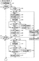
次に、パチンコ機1の主基板41による動作について、図7を参照して説明する。図7は、主基板41におけるメイン処理のフローチャートである。以下、フローチャートの各ステップについて「S」と略記する。パチンコ機1の主基板41による制御は、ROM53の制御プログラム記憶エリアに記憶されている制御プログラムにより行われる。制御プログラムのメイン処理は、割込信号発生回路57(図5参照)が発生する割込信号をCPU51が感知した際に、CPU51において実行される。割込信号は、一定の間隔(本実施の形態では2ms)毎に発生されるので、メイン処理は2ms毎に繰り返し実行されることになる。   Next, the operation of the main board 41 of the pachinko machine 1 will be described with reference to FIG. FIG. 7 is a flowchart of main processing in the main board 41. Hereinafter, each step of the flowchart is abbreviated as “S”. Control by the main board 41 of the pachinko machine 1 is performed by a control program stored in a control program storage area of the ROM 53. The main process of the control program is executed by the CPU 51 when the CPU 51 senses an interrupt signal generated by the interrupt signal generation circuit 57 (see FIG. 5). Since the interrupt signal is generated at regular intervals (2 ms in the present embodiment), the main process is repeatedly executed every 2 ms.

図7に示すように、割込信号の感知によってメイン処理が開始されると、まず、コマンド出力処理が行われる(S10)。このコマンド出力処理では、制御コマンドが、I/Oインタフェイス54を介してサブ統合基板58や払出制御基板45、中継基板47等に出力される。制御コマンドには、決定された特別図柄を示す特別図柄指定コマンド、決定された変動パターンを指示すると共にデモ図柄の変動開始を指示する変動パターン指定コマンド、変動している特別図柄の停止を指示する特別図柄停止コマンド、大当たり遊技を開始させることを示す大当たり遊技開始コマンド、第一大入賞口16又は第二大入賞口17の開放を指示する大入賞口開放コマンド、大当たり遊技が終了したことを示す大当たり遊技終了コマンド等、多数のコマンドがある。ここで出力される制御コマンドは、前回実施されたメイン処理においてコマンド関係記憶エリア5209に出力コマンドとして記憶された制御コマンドである。   As shown in FIG. 7, when the main process is started by sensing an interrupt signal, first, a command output process is performed (S10). In this command output process, a control command is output to the sub-integrated board 58, the payout control board 45, the relay board 47, etc. via the I / O interface 54. In the control command, a special symbol designating command indicating the determined special symbol, a variation pattern designating command instructing the determined variation pattern and instructing the start of variation of the demo symbol, and instructing the stop of the varying special symbol Special symbol stop command, jackpot game start command indicating start of jackpot game, jackpot opening command instructing opening of the first jackpot 16 or the second jackpot 17, indicating that the jackpot game has ended There are a number of commands such as a jackpot game end command. The control command output here is a control command stored as an output command in the command relation storage area 5209 in the main process executed last time.

次いで、スイッチ読込処理が行われる(S11)。このスイッチ読込処理では、普通図柄始動ゲート12、特別図柄始動電動役物15、第一大入賞口16、及び第二大入賞口17への遊技球の入賞を検知する処理が行われる。具体的には、これらの入賞口に設けられた各スイッチ(図5参照)により遊技球が検出されたか否かが判断される。そして、遊技球が検出された場合には、RAM52に記憶された各スイッチに対応したフラグがONとされる。   Next, a switch reading process is performed (S11). In this switch reading process, a process of detecting a winning of a game ball in the normal symbol starting gate 12, the special symbol starting electric accessory 15, the first grand prize winning port 16, and the second major winning prize port 17 is performed. Specifically, it is determined whether or not a game ball is detected by each switch (see FIG. 5) provided in these winning openings. When a game ball is detected, the flag corresponding to each switch stored in the RAM 52 is turned ON.

次いで、カウンタ更新処理が行われる(S12)。このカウンタ更新処理では、RAM52のカウンタ記憶エリアに記憶されている乱数取得カウンタの各値が所定量だけ加算され、タイマカウンタの各値が所定量だけ減算される。   Next, a counter update process is performed (S12). In this counter update process, each value of the random number acquisition counter stored in the counter storage area of the RAM 52 is added by a predetermined amount, and each value of the timer counter is subtracted by a predetermined amount.

次いで、特別電動役物処理が行われる(S13)。この特別電動役物処理では、第一大入賞口16又は第二大入賞口17の開閉動作を指示するための大入賞口開放コマンド、大入賞口閉鎖コマンド等の制御コマンドをサブ統合基板58へ送信するための処理が行われる。第一大入賞口16は、15ラウンド大当たり遊技中に開閉され、一旦開放された第一大入賞口16は、1回の開放動作における最大開放時間である30秒が経過するか、又は9個の遊技球の入賞が検出されると閉鎖する。そして、この動作が15回繰り返されると大当たり遊技が終了する。また、第二大入賞口17は、2ラウンド大当たり遊技中及び小当たり遊技中に開閉され、最大開放時間である2秒の経過、又は9個の遊技球の入賞を契機として閉鎖する。そして、この動作が2回繰り返されると当たり遊技が終了する。特別電動役物処理では、大当たり遊技が終了すると、大当たりと判定される割合が通常よりも高くなる確率変動状態や、特別図柄始動電動役物15が開放される割合が通常よりも高くなる時短状態等、各種遊技状態を制御する処理が行われる。そして、大当たり遊技が終了したことを示す大当たり遊技終了コマンドがRAM52に記憶される。   Next, special electric accessory processing is performed (S13). In this special electric accessory processing, control commands such as a big prize opening command and a big prize opening closing command for instructing the opening / closing operation of the first big prize opening 16 or the second big prize opening 17 are sent to the sub-integrated board 58. Processing for transmission is performed. The first grand prize opening 16 is opened and closed during 15 rounds of jackpot game, and once the first big prize opening 16 has been opened, 30 seconds, which is the maximum opening time in one opening operation, has elapsed, or 9 It closes when a winning game ball is detected. And if this operation is repeated 15 times, the jackpot game ends. The second grand prize winning opening 17 is opened and closed during the two round big hit game and the small hit game, and is closed when the maximum opening time of 2 seconds elapses or when nine game balls are won. Then, when this operation is repeated twice, the winning game ends. In the special electric accessory processing, when the jackpot game is over, the probability variation state in which the ratio determined to be a big hit is higher than normal, or the short time state in which the ratio at which the special symbol start electric bonus 15 is opened is higher than normal. A process for controlling various game states is performed. Then, a jackpot game end command indicating that the jackpot game has ended is stored in the RAM 52.

次いで、特別図柄処理が行われる(S14)。この特別図柄処理では、特別図柄始動電動役物15への遊技球の入賞を契機として乱数が取得され、取得された乱数が大当たり関係情報記憶エリア(図6参照)に記憶される。そして、第一〜第四記憶エリアのうち、番号の若い記憶エリアの乱数から順次大当たり判定が行われ、大当たり判定の結果及び変動パターン決定乱数の値により変動パターンが決定されて、決定された変動パターンを指定する変動パターン指定コマンドがRAM52に記憶される。サブ統合基板58は、変動パターン指定コマンドを受信すると、デモ図柄の変動を開始させると共に、指定された変動パターンに応じて、大当たり判定の結果を示す報知演出を制御する。また、図柄表示部11に表示される特別図柄の決定、指示、デモ図柄及び特別図柄の変動終了を指示する特別図柄停止コマンドの記憶等の処理が行われる。   Next, special symbol processing is performed (S14). In this special symbol process, a random number is acquired in response to a winning of a game ball to the special symbol starting electric accessory 15 and the acquired random number is stored in the jackpot relation information storage area (see FIG. 6). Then, among the first to fourth storage areas, the jackpot determination is performed sequentially from the random number of the storage area with the smallest number, the variation pattern is determined based on the result of the jackpot determination and the value of the variation pattern determination random number, and the determined variation A variation pattern designation command for designating a pattern is stored in the RAM 52. When the sub-integrated board 58 receives the variation pattern designation command, the sub-integrated substrate 58 starts the demonstration symbol variation and controls the notification effect indicating the result of the jackpot determination according to the designated variation pattern. Also, processing such as determination of special symbols displayed on the symbol display unit 11, instruction, storage of a special symbol stop command for instructing the end of variation of the demo symbols and special symbols, and the like are performed.

次いで、普通電動役物処理が行われる(S15)。この普通電動役物処理では、普通当たりとなった場合に、特別図柄始動電動役物15に設けられた一対の開閉部材(所謂チューリップ)の開閉(普通当たり遊技中の動作)の制御が行われる。開閉部材が開放されることにより、特別図柄始動電動役物15への遊技球の入賞が容易となる。   Next, ordinary electric accessory processing is performed (S15). In this ordinary electric accessory processing, when a normal hit is reached, the opening / closing (operation during normal hit game) of a pair of opening / closing members (so-called tulips) provided in the special symbol starting electric accessory 15 is controlled. . By opening the opening / closing member, it becomes easy to win a game ball to the special symbol starting electric accessory 15.

次いで、普通図柄処理が行われる(S16)。この普通図柄処理では、普通当たり乱数の取得、普通当たり判定等が行われる。まず、スイッチ読込処理(S11)にて普通図柄始動ゲート12への遊技球の通過が検出されると、普通当たり判定カウンタの値が普通当たり乱数として取得される。そして、普通当たり判定が行われて、図柄表示部11の普通図柄を変動及び停止させることで判定結果が報知される。   Next, normal symbol processing is performed (S16). In this normal symbol processing, normal random numbers are obtained, normal hit determination, and the like are performed. First, when the passing of the game ball to the normal symbol start gate 12 is detected in the switch reading process (S11), the value of the normal hit determination counter is acquired as a normal hit random number. Then, the normal hit determination is performed, and the determination result is notified by changing and stopping the normal symbol on the symbol display unit 11.

次いで、賞品球の払い出しを行う払出処理(S17)、及びエラーチェック(S18)が行われる。パチンコ機1にエラーが発生している場合には、表示画面28にエラー表示を行わせたり、照明装置35を点灯・点滅させたり、スピーカ48,48にエラー音を発音させたりする。そこで、S10のコマンド出力処理にてサブ統合基板58へ送信するためのエラーコマンドがRAM52のコマンド関係記憶エリア5209に記憶される。次いで、情報出力処理(S19)において、図示外の遊技場管理用コンピュータにパチンコ機1の大当たり情報、始動情報等の各種の情報が出力ポート55を介して出力される。情報出力処理が終わるとメイン処理は終了する。そして、割込信号発生回路57から割込信号を受信すると、また最初からメイン処理が実行される。   Next, a payout process (S17) for paying out prize balls and an error check (S18) are performed. If an error has occurred in the pachinko machine 1, an error is displayed on the display screen 28, the lighting device 35 is lit or blinked, or an error sound is generated on the speakers 48, 48. Therefore, an error command for transmission to the sub-integrated board 58 in the command output process of S10 is stored in the command relation storage area 5209 of the RAM 52. Next, in the information output process (S19), various kinds of information such as jackpot information, starting information, etc. of the pachinko machine 1 are output via the output port 55 to a game hall management computer (not shown). When the information output process ends, the main process ends. When the interrupt signal is received from the interrupt signal generation circuit 57, the main process is executed again from the beginning.

次に、サブ統合基板58における処理について説明する。サブ統合基板では、主基板41から送信されるコマンドに従って、表示画面28、役物装置30、照明装置35、スピーカ48等を制御する処理が行われる。すなわち、主基板41において行われた種々の判定結果に応じて、演出を総合的に制御する。特に、パチンコ機1では、操作ボタン20の操作に応じて演出を制御することができるが、操作ボタン20の操作部96が深く押し込まれた状態で保持され、ボタンのオート状態が設定されると、遊技者によって操作ボタン20が操作された場合と同じ演出を実行する。この点に本発明の特徴を有する。   Next, processing in the sub integrated substrate 58 will be described. In the sub-integrated substrate, processing for controlling the display screen 28, the accessory device 30, the illumination device 35, the speaker 48, and the like is performed in accordance with a command transmitted from the main substrate 41. That is, the effect is comprehensively controlled according to various determination results made on the main board 41. In particular, in the pachinko machine 1, the production can be controlled in accordance with the operation of the operation button 20, but when the operation unit 96 of the operation button 20 is held in a deeply pressed state and the automatic state of the button is set. The same effect as when the operation button 20 is operated by the player is executed. This is a feature of the present invention.

まず、サブ統合基板58のRAM582について説明する。RAM582には、主基板41により指定された変動パターンが記憶される変動パターン記憶エリア、演出制御基板43やランプドライバ基板46に出力される制御コマンドが記憶されるコマンド関係記憶エリア、各種フラグが記憶されるフラグ関係記憶エリア、各種カウンタが記憶されるカウンタ記憶エリア等の各種記憶エリアが設けられている。   First, the RAM 582 of the sub integrated substrate 58 will be described. The RAM 582 stores a variation pattern storage area for storing a variation pattern designated by the main board 41, a command-related storage area for storing control commands output to the effect control board 43 and the lamp driver board 46, and various flags. Various storage areas such as a flag related storage area and a counter storage area for storing various counters are provided.

フラグ関係記憶エリアに記憶されている主なフラグとして、予告演出実行フラグ、隠し演出実行フラグ、報知演出実行フラグ、大当たり遊技演出実行フラグ、及び押下検出フラグがある。予告演出実行フラグは、遊技者に操作ボタン20の操作を促し、ボタンが操作されたか否かに応じて制御される演出である予告演出を実行することが決定されている場合に「ON」とされる。隠し演出実行フラグは、遊技者に操作ボタン20の操作を促すことなく、ボタンが操作されたか否かに応じて制御される演出である隠し演出を実行することが決定されている場合に「ON」とされる。報知演出実行フラグは、報知演出制御処理(図9乃至図16参照)を実行するか否かを決定するためのフラグであり、このフラグが「ON」となっている場合のみ、報知演出制御処理が実行される。同様に、大当たり遊技演出実行フラグが「ON」となっている場合のみ、大当たり遊技演出処理(図17参照)が実行される。そして、押下検出フラグは、操作ボタン20が手動で押下された場合、及びオート状態によって操作ボタン20が押下されたとみなされた場合に「ON」とされる。   Main flags stored in the flag-related storage area include a notice effect execution flag, a hidden effect execution flag, a notification effect execution flag, a jackpot game effect execution flag, and a press detection flag. The notice effect execution flag is “ON” when it is determined to prompt the player to operate the operation button 20 and to execute the notice effect that is an effect controlled according to whether or not the button is operated. Is done. The hidden effect execution flag is “ON” when it is determined to execute the hidden effect that is an effect controlled according to whether or not the button is operated without prompting the player to operate the operation button 20. " The notification effect execution flag is a flag for determining whether or not to execute the notification effect control process (see FIGS. 9 to 16), and only when the flag is “ON”, the notification effect control process. Is executed. Similarly, the jackpot game effect process (see FIG. 17) is executed only when the jackpot game effect execution flag is “ON”. The press detection flag is set to “ON” when the operation button 20 is pressed manually and when the operation button 20 is considered to be pressed due to the auto state.

カウンタ記憶エリアには、主に、操作有効期間カウンタ、連打回数カウンタ、及びラウンド数計数カウンタが記憶されている。操作有効期間カウンタは、操作ボタン20の操作が有効となる期間である操作有効期間を計測するためのタイマカウンタである。連打回数カウンタは、1回の操作有効期間中に操作ボタン20が断続的に操作された累計の回数を計数するカウンタである。ラウンド数計数カウンタは、1回の大当たり遊技中に行われる大入賞口16,17の開閉動作の回数(ラウンド数)を計数するためのカウンタである。   The counter storage area mainly stores an operation effective period counter, a continuous hit count counter, and a round count counter. The operation valid period counter is a timer counter for measuring an operation valid period that is a period during which the operation of the operation button 20 is valid. The repeated hit counter is a counter that counts the cumulative number of times that the operation button 20 has been operated intermittently during one operation effective period. The round number counting counter is a counter for counting the number of opening / closing operations (number of rounds) of the big winning openings 16, 17 performed during one big hit game.

次いで、サブ統合基板58のROM583について説明する。ROM583には、CPU581がパチンコ機1の制御を補助するための各種プログラムが記憶されるプログラム記憶エリア、サブ統合基板58から演出制御基板43やランプドライバ基板46に出力される制御コマンドのテーブルが記憶される制御コマンドテーブル記憶エリア等の各種記憶エリアが設けられている。   Next, the ROM 583 of the sub integrated board 58 will be described. The ROM 583 stores a program storage area for storing various programs for the CPU 581 to assist the control of the pachinko machine 1, and a table of control commands output from the sub-integrated board 58 to the effect control board 43 and the lamp driver board 46. Various storage areas such as a control command table storage area are provided.

次に、サブ統合基板58で行われるサブ統合基板処理、報知演出制御処理、及び大当たり遊技演出処理について、図8乃至図17を参照して説明する。図8は、サブ統合基板58で行われるサブ統合基板処理のフローチャートであり、図9及び図11は、サブ統合基板58で行われる報知演出制御処理のフローチャートであり、図10は、箱120及びボタン操作指示121の表示態様の一例を示す図である。また、図12は、報知演出制御処理の中で行われる役物リーチ制御処理のサブルーチンのフローチャートであり、図13は、ボタン連打指示123及び遊技説明124の表示態様の一例を示す図である。また、図14は、報知演出制御処理の中で行われる演出選択リーチ制御処理のサブルーチンのフローチャートであり、図15は、演出候補126、演出選択指示メッセージ127、及びオート解除誘導メッセージ128の表示態様の一例を示す図である。また、図16は、報知演出制御処理の中で行われる押下時間指定演出制御処理のサブルーチンのフローチャートであり、図17は、サブ統合基板58で行われる大当たり遊技演出処理のフローチャートである。サブ統合基板処理は、主基板41からコマンドを受信した場合に、CPU581において実行される。また、報知演出制御処理は、報知演出実行フラグが「ON」とされており、且つサブ統合基板処理が行われていない間にCPU581において実行され、大当たり遊技演出処理は、大当たり遊技演出実行フラグが「ON」とされており、且つサブ統合基板処理が行われていない間にCPU581において実行される。   Next, sub-integrated board processing, notification effect control processing, and jackpot game effect processing performed on the sub-integrated board 58 will be described with reference to FIGS. FIG. 8 is a flowchart of the sub-integrated board process performed on the sub-integrated board 58, FIGS. 9 and 11 are flowcharts of the notification effect control process performed on the sub-integrated board 58, and FIG. It is a figure which shows an example of the display mode of the button operation instruction | indication 121. FIG. FIG. 12 is a flowchart of a subroutine for the accessory reach control process performed in the notification effect control process, and FIG. 13 is a diagram showing an example of a display mode of the button hitting instruction 123 and the game description 124. FIG. 14 is a flowchart of a subroutine of the effect selection reach control process performed in the notification effect control process, and FIG. 15 is a display mode of the effect candidate 126, the effect selection instruction message 127, and the auto release guidance message 128. It is a figure which shows an example. FIG. 16 is a flowchart of a subroutine of a press time designation effect control process performed in the notification effect control process, and FIG. 17 is a flowchart of a jackpot game effect process performed in the sub-integrated board 58. The sub integrated substrate processing is executed by the CPU 581 when a command is received from the main substrate 41. Further, the notification effect control process is executed by the CPU 581 while the notification effect execution flag is set to “ON” and the sub-integrated board processing is not performed, and the jackpot game effect processing flag is set to the jackpot game effect execution flag. The CPU 581 executes “ON” while the sub-integrated substrate processing is not performed.

図8に示すように、サブ統合基板処理が開始されると、まず、変動パターン指定コマンドを受信したか否かが判断される(S21)。受信した場合には(S21:YES)、コマンドによって指定された変動パターンがRAM582に記憶され(S22)、予告演出を実行するか否かが、指定された変動パターンに応じて抽選される(S23)。本実施の形態における予告演出とは、表示画面28に箱を表示させて操作ボタン20の操作を促し、操作ボタン20が操作された場合に箱から予告図柄(饅頭)を出現させる演出である。そして、指定された変動パターンが、大当たり時に実行される割合が他の演出よりも高い(大当たりの期待度が高い)リーチ演出の変動パターンであれば、予告演出が実行される割合が高くなるように実行抽選が行われる。   As shown in FIG. 8, when the sub-integrated substrate processing is started, it is first determined whether or not a variation pattern designation command has been received (S21). If received (S21: YES), the variation pattern designated by the command is stored in the RAM 582 (S22), and whether or not the notice effect is to be executed is selected according to the designated variation pattern (S23). ). The notice effect in the present embodiment is an effect in which a box is displayed on the display screen 28 to prompt the user to operate the operation button 20, and when the operation button 20 is operated, a notice symbol (wharf) appears from the box. If the specified variation pattern is a variation pattern of a reach effect that has a higher rate of execution at the jackpot than other effects (higher expectation of the jackpot), the rate at which the notice effect is executed is higher. An execution lottery is performed.

予告演出の実行抽選に当選した場合には(S25:YES)、予告図柄の態様が変動パターンに応じて決定される(S26)。指定された変動パターンが大当たりの変動パターンであれば、大当たりの期待度が高いことを示す予告図柄が決定され易い。そして、予告演出を実行するか否かを示す予告演出実行フラグが、実行することを示す「ON」とされ(S27)、報知演出制御処理を実行するか否かを示す報知演出実行フラグが「ON」とされて(S28)、サブ統合基板処理が終了する。報知演出実行フラグが「ON」とされると、報知演出制御処理が実行されるが、この詳細は後述する。   When the lottery for the notice effect is won (S25: YES), the aspect of the notice symbol is determined according to the variation pattern (S26). If the specified variation pattern is a jackpot variation pattern, it is easy to determine a notice symbol indicating that the expectation of jackpot is high. Then, the notice effect execution flag indicating whether or not to execute the notice effect is set to “ON” indicating execution (S27), and the notification effect execution flag indicating whether or not to execute the notification effect control process is “ ON "(S28), the sub-integrated substrate processing is completed. When the notification effect execution flag is set to “ON”, the notification effect control process is executed, which will be described later in detail.

一方で、予告演出の実行抽選に当選しなかった場合には(S25:NO)、隠し演出を実行するか否かが、指定された変動パターンに応じて抽選される(S30)。隠し演出とは、操作ボタン20の操作が有効となっていることを遊技者に報知することなく、操作ボタン20が操作されたか否かに応じて制御される演出である。本実施の形態では、デモ図柄の背景に表示させている花を咲かせる演出や、池から魚を登場させる演出等が隠し演出として用意されている。隠し演出の実行抽選に当選しなかった場合には(S31:NO)、そのまま報知演出実行フラグが「ON」とされて(S28)、サブ統合基板処理が終了する。当選した場合には(S31:YES)、隠し演出の態様が変動パターンに応じて決定される(S33)。指定された変動パターンが大当たりの変動パターンであれば、先述した予告図柄の態様と同様に、大当たりの期待度が高いことを示す隠し演出の態様が決定され易い。そして、隠し演出実行フラグが、隠し演出を実行することを示す「ON」とされ(S34)、報知演出実行フラグが「ON」とされて(S28)、サブ統合基板処理が終了する。   On the other hand, if the execution lottery for the notice effect is not won (S25: NO), whether or not to execute the hidden effect is drawn according to the designated variation pattern (S30). The hidden effect is an effect that is controlled according to whether or not the operation button 20 is operated without notifying the player that the operation of the operation button 20 is valid. In the present embodiment, an effect of making the flower displayed in the background of the demo symbol bloom, an effect of making fish appear from the pond, and the like are prepared as a hidden effect. When the hidden effect execution lottery is not won (S31: NO), the notification effect execution flag is set to “ON” as it is (S28), and the sub-integrated board processing is ended. When winning (S31: YES), the mode of the hidden effect is determined according to the variation pattern (S33). If the specified variation pattern is a jackpot variation pattern, the hidden effect mode indicating that the expectation level for the jackpot is high is easily determined as in the case of the notice symbol pattern described above. Then, the hidden effect execution flag is set to “ON” indicating that the hidden effect is executed (S34), the notification effect execution flag is set to “ON” (S28), and the sub-integrated board processing is ended.

また、変動パターン指定コマンドを受信していない場合には(S21:NO)、特別図柄停止コマンドを受信したか否かが判断される(S37)。受信した場合には(S37:YES)、報知演出を終了させる処理、具体的には、デモ図柄を確定表示させる処理が行われて(S38)、報知演出実行フラグが「OFF」とされ(S39)、サブ統合基板処理が終了する。   If the variation pattern designation command has not been received (S21: NO), it is determined whether or not a special symbol stop command has been received (S37). If received (S37: YES), a process for ending the notification effect, specifically, a process for confirming and displaying the demo symbol (S38) is performed, and the notification effect execution flag is set to “OFF” (S39). ), The sub-integrated substrate processing ends.

また、特別図柄停止コマンドを受信していない場合には(S37:NO)、大当たり遊技開始コマンドを受信したか否かが判断される(S41)。受信していない場合には(S41:NO)、受信したコマンドに応じたその他の処理が行われて(S44)、サブ統合基板処理が終了する。受信した場合には(S41:YES)、大当たり遊技演出実行フラグが、大当たり遊技演出処理を実行することを示す「ON」とされて(S42)、サブ統合基板処理が終了する。大当たり遊技演出実行フラグが「ON」とされると、大当たり遊技演出処理が実行されるが、この詳細は図17を参照して後述する。   If a special symbol stop command has not been received (S37: NO), it is determined whether a jackpot game start command has been received (S41). If not received (S41: NO), other processing corresponding to the received command is performed (S44), and the sub-integrated substrate processing is terminated. If received (S41: YES), the jackpot game effect execution flag is set to “ON” indicating that the jackpot game effect process is to be executed (S42), and the sub-integrated board process ends. When the jackpot game effect execution flag is set to “ON”, the jackpot game effect process is executed. This will be described later with reference to FIG.

次に、図9乃至図11を参照して、報知演出制御処理について説明する。先述したように、報知演出制御処理は、主基板41から変動パターン指定コマンドを受信することを契機として行われる。まず、表示画面28に表示されているデモ図柄の変動が開始され(S47)、予告演出実行フラグが「ON」となっているか否かが判断される(S48)。予告演出を実行することを示す「ON」となっている場合には(S48:YES)、箱120(図10参照)を表示させる処理が演出制御基板43に対して行われる(S50)。   Next, the notification effect control process will be described with reference to FIGS. 9 to 11. As described above, the notification effect control process is performed in response to receiving a variation pattern designation command from the main board 41. First, the change of the demo symbol displayed on the display screen 28 is started (S47), and it is determined whether or not the notice effect execution flag is “ON” (S48). When it is “ON” indicating that the notice effect is to be executed (S48: YES), a process for displaying the box 120 (see FIG. 10) is performed on the effect control board 43 (S50).

そして、操作ボタン20のオート状態が設定されているか否かが判断される(S51)。この判断は、操作ボタン20の操作部96(図3及び図4参照)が押し込まれた状態で保持されていることが、押し込み検出スイッチ98によって検出されているか否かによって行われる。操作部96が押し込まれておらず、オート状態の設定中でないと判断された場合には(S51:NO)、操作ボタン20の操作を促すボタン操作指示121を表示させる処理が、演出制御基板43に対して行われる(S52)。すると、図10に示すように、表示画面28には、箱120と共に、「ボタンを押してね」というメッセージと下向きの矢印とからなるボタン操作指示121が表示される。そして、操作有効報知LED97(図3及び図4参照)が点灯されて、操作ボタン20の操作が有効となっていることが遊技者に報知され(S53)、操作ボタン20の操作有効期間を計測するための操作有効期間カウンタがセットされる(S54)。   Then, it is determined whether or not the automatic state of the operation button 20 is set (S51). This determination is made based on whether or not the push-in detection switch 98 has detected that the operation unit 96 (see FIGS. 3 and 4) of the operation button 20 is being pushed in. When it is determined that the operation unit 96 has not been pushed in and the auto state is not being set (S51: NO), the process of displaying the button operation instruction 121 that prompts the operation of the operation button 20 is performed. (S52). Then, as shown in FIG. 10, on the display screen 28, a button operation instruction 121 including a message “Please press the button” and a downward arrow is displayed together with the box 120. Then, the operation validity notification LED 97 (see FIGS. 3 and 4) is turned on to notify the player that the operation of the operation button 20 is valid (S53), and the operation validity period of the operation button 20 is measured. An operation valid period counter is set (S54).

次いで、操作ボタン20が押下されたか否かが、押下検出スイッチ99によって判断される(S56)。そして、押下されていなければ(S56:NO)、操作有効期間が経過したか否かが操作有効期間カウンタによって判断され(S57)、経過していなければ(S57:NO)、S56の判断へ戻る。操作有効期間が経過する前に操作ボタン20が押下された場合には(S56:YES)、ボタン操作指示121が表示画面28から消去され(S59)、操作有効報知LED97を消灯させる処理が行われる(S60)。次いで、決定されている態様の予告図柄を箱120から出現させる処理が行われて(S61)、所定時間表示された後、箱120及び予告図柄が消去される(S62)。そして、予告演出実行フラグが「OFF」とされて(S63)、S81(図11参照)の判断へ移行する。また、操作ボタン20が押下されることなく操作有効期間が経過した場合には(S57:YES)、ボタン操作指示121が消去され(S65)、操作有効報知LED97が消灯される(S66)。そして、箱120が消去され(S67)、予告演出実行フラグが「OFF」とされて(S63)、S81の判断へ移行する。   Next, whether or not the operation button 20 has been pressed is determined by the press detection switch 99 (S56). If it is not pressed (S56: NO), it is determined by the operation effective period counter whether or not the operation effective period has elapsed (S57). If not (S57: NO), the process returns to the determination of S56. . When the operation button 20 is pressed before the operation valid period elapses (S56: YES), the button operation instruction 121 is deleted from the display screen 28 (S59), and a process for turning off the operation validity notification LED 97 is performed. (S60). Next, a process of causing the determined advance notice symbol to appear from the box 120 is performed (S61), and after displaying for a predetermined time, the box 120 and the advance notice symbol are deleted (S62). Then, the notice effect execution flag is set to “OFF” (S63), and the process proceeds to the determination of S81 (see FIG. 11). If the operation valid period has passed without the operation button 20 being pressed (S57: YES), the button operation instruction 121 is deleted (S65), and the operation validity notification LED 97 is turned off (S66). Then, the box 120 is deleted (S67), the notice effect execution flag is set to “OFF” (S63), and the process proceeds to S81.

一方で、操作ボタン20の操作部96が押し込まれた状態で保持されており、オート状態の設定中であると判断された場合には(S51:YES)、遊技者が操作ボタン20を押下しなくとも、箱120から予告図柄を出現させる処理が行われる(S61)。そして、箱120及び予告図柄が消去され(S62)、予告演出実行フラグが「OFF」とされて(S63)、S81の判断へ移行する。   On the other hand, when the operation unit 96 of the operation button 20 is held in the depressed state and it is determined that the automatic state is being set (S51: YES), the player presses the operation button 20 down. Even if not, the process of causing the notice symbol to appear from the box 120 is performed (S61). Then, the box 120 and the notice symbol are deleted (S62), the notice effect execution flag is set to “OFF” (S63), and the process proceeds to the determination of S81.

このように、本実施の形態によると、操作ボタン20のオート状態を設定すると、遊技者は、操作ボタン20を実際に押下することなく、押下した場合と同じ予告演出を楽しむことができる。また、オート状態を解除すれば、操作ボタン20を操作して予告図柄を出現させるか否かを遊技者自身が選択することができる。   Thus, according to this embodiment, when the automatic state of the operation button 20 is set, the player can enjoy the same notice effect as when the operation button 20 is pressed without actually pressing the operation button 20. If the auto state is canceled, the player himself can select whether or not to make the notice symbol appear by operating the operation button 20.

また、予告演出実行フラグが「OFF」となっている場合には(S48:NO)、隠し演出実行フラグが「ON」となっているか否かが判断される(S70)。隠し演出を実行しないことを示す「OFF」となっている場合には(S70:NO)、そのままS81の判断へ移行する。隠し演出を実行することを示す「ON」となっている場合には(S70:YES)、操作ボタン20のオート状態が設定されているか否かが判断される(S71)。   When the notice effect execution flag is “OFF” (S48: NO), it is determined whether or not the hidden effect execution flag is “ON” (S70). If it is “OFF” indicating that the hidden effect is not executed (S70: NO), the process proceeds to S81 as it is. When it is “ON” indicating that the hidden effect is executed (S70: YES), it is determined whether or not the automatic state of the operation button 20 is set (S71).

オート状態が設定されていなければ(S71:NO)、ボタンの操作が有効となっていることは遊技者に報知されることなく、操作有効期間カウンタがセットされ(S72)、操作ボタン20が押下されたか否かが判断される(S73)。そして、押下されていなければ(S73:NO)、操作有効期間が経過したか否かが判断され(S74)、経過していなければ(S74:NO)、S73の判断へ戻る。操作有効期間が経過する前に操作ボタン20が押下された場合には(S73:YES)、決定されている態様の隠し演出を実行する処理が行われ(S76)、隠し演出実行フラグが「OFF」とされて(S77)、S81の判断へ移行する。操作ボタン20が操作されることなく操作有効期間が経過した場合には(S74:YES)、隠し演出は実行されることなく、隠し演出実行フラグが「OFF」とされて(S77)、S81の判断へ移行する。一方で、操作ボタン20のオート状態が設定されている場合には(S71:YES)、遊技者が操作ボタン20を押下しなくとも、決定されている態様の隠し演出が実行されて(S76)、隠し演出実行フラグが「OFF」とされ(S77)、S81の判断へ移行する。   If the auto state is not set (S71: NO), the operation valid period counter is set without notifying the player that the button operation is valid (S72), and the operation button 20 is pressed. It is determined whether or not it has been done (S73). If it is not pressed (S73: NO), it is determined whether or not the operation valid period has elapsed (S74). If not (S74: NO), the process returns to the determination of S73. When the operation button 20 is pressed before the operation valid period elapses (S73: YES), a process for executing the hidden effect in the determined mode is performed (S76), and the hidden effect execution flag is set to “OFF”. (S77), the process proceeds to S81. When the operation valid period has passed without the operation button 20 being operated (S74: YES), the hidden effect execution flag is set to “OFF” without executing the hidden effect (S77), and the operation of S81 is performed. Transition to judgment. On the other hand, when the automatic state of the operation button 20 is set (S71: YES), the hidden effect of the determined mode is executed without the player pressing the operation button 20 (S76). Then, the hidden effect execution flag is set to “OFF” (S77), and the process proceeds to S81.

このように、本実施の形態では、操作ボタン20の操作が有効となっていることは報知されずに、ボタンの操作を契機として行われる演出である、所謂隠し演出を実行することができる。よって、遊技者は、オート状態を解除して手動で操作ボタン20を押下することで、隠し演出が行われることを期待して遊技を楽しむことができる。また、オート状態を設定すれば、隠し演出の実行タイミングが分からない場合や、ボタン操作が面倒な場合でも、隠し演出を楽しむことができる。すなわち、遊技者は、操作ボタン20のオート機能を設定するか否かを自ら選択することで、様々な形で演出を楽しむことができる。   Thus, in the present embodiment, it is possible to execute a so-called hidden effect, which is an effect that is performed when the operation of the button 20 is performed, without notifying that the operation of the operation button 20 is valid. Therefore, the player can enjoy the game in expectation that a hidden effect will be performed by canceling the auto state and manually pressing the operation button 20. If the auto state is set, the hidden effect can be enjoyed even when the execution timing of the hidden effect is not known or the button operation is troublesome. That is, the player can enjoy the effects in various forms by selecting whether or not to set the automatic function of the operation button 20 by himself / herself.

次いで、図11に示すように、主基板41から指定された変動パターンが、リーチ演出を実行しない「非リーチ」の変動パターンであるか否かが判断される(S81)。「非リーチ」の変動パターンであれば(S81:YES)、左右のデモ図柄が異なるように左、右、中の順でデモ図柄を停止させて、デモ図柄を確定表示させる処理が行われて(S82)、報知演出制御処理が終了する。「非リーチ」の変動パターンでなければ(S81:NO)、リーチを成立させるために、左右のデモ図柄が同一となるように左、右の順でデモ図柄を停止させる処理が行われる(S83)。   Next, as shown in FIG. 11, it is determined whether or not the variation pattern designated from the main board 41 is a “non-reach” variation pattern in which the reach effect is not executed (S81). If the variation pattern is “non-reach” (S81: YES), the demo symbols are stopped in the order of left, right, and middle so that the left and right demo symbols are different, and a process of confirming and displaying the demo symbols is performed. (S82), the notification effect control process ends. If the fluctuation pattern is not “non-reach” (S81: NO), in order to establish reach, a process of stopping the demo symbols in order of left and right is performed so that the left and right demo symbols are the same (S83). ).

そして、役物装置30を動作させるリーチ演出を実行する「役物リーチ」の変動パターンであるか否かが判断され(S85)、「役物リーチ」の変動パターンであれば(S85:YES)、役物リーチ制御処理が行われて、報知演出制御処理が終了する。「役物リーチ」の変動パターンでなければ(S85:NO)、複数のリーチ演出からいずれか1つを遊技者に選択させて実行する「演出選択リーチ」の変動パターンであるか否かが判断される(S87)。「演出選択リーチ」の変動パターンであれば(S87:YES)、演出選択リーチ制御処理が行われて(S88)、処理が終了する。「演出選択リーチ」の変動パターンでなければ(S87:NO)、操作ボタン20の押下時間に応じてリーチ演出の内容を制御する「押下時間指定演出」の変動パターンであるか否かが判断される(S89)。「押下時間指定演出」の変動パターンであれば(S89:YES)、押下時間指定演出制御処理が行われて(S90)、処理が終了する。また、「押下時間指定演出」の変動パターンでもなければ(S89:NO)、操作ボタン20の操作を伴わないリーチ演出の変動パターンであり、変動パターンに応じてリーチ演出が制御されて(S91)、処理が終了する。以下、操作ボタン20の操作を伴うリーチ演出の制御処理である、役物リーチ制御処理、演出選択リーチ制御処理、及び押下時間指定演出制御処理の詳細について説明する。   Then, it is determined whether or not the variation pattern of the “actual reach” for performing the reach effect for operating the accessory device 30 (S85). If the variation pattern of the “actual reach” is determined (S85: YES). Then, the accessory reach control process is performed, and the notification effect control process ends. If it is not the “actual reach reach” variation pattern (S85: NO), it is determined whether or not it is the variation pattern of “production selection reach” that is executed by selecting one of a plurality of reach productions. (S87). If it is the variation pattern of “effect selection reach” (S87: YES), the effect selection reach control process is performed (S88), and the process ends. If it is not the variation pattern of “effect selection reach” (S87: NO), it is determined whether or not it is the variation pattern of “depression time designation effect” that controls the contents of reach effect according to the pressing time of the operation button 20. (S89). If it is a variation pattern of “pressing time designation effect” (S89: YES), a pressing time designation effect control process is performed (S90), and the process ends. If it is not the variation pattern of “pressing time designation effect” (S89: NO), it is the variation pattern of the reach effect that does not involve the operation of the operation button 20, and the reach effect is controlled according to the change pattern (S91). , The process ends. Hereinafter, details of the reach effect control process, the effect selection reach control process, and the pressing time designation effect control process, which are the reach effect control processes accompanying the operation of the operation buttons 20, will be described.

次に、図12及び図13を参照して、報知演出制御処理中で行われる役物リーチ制御処理について説明する。役物装置30を動作させるリーチ演出を実行する「役物リーチ」の変動パターンが指定された場合、ボタン連打指示123(図13参照)が表示画面28に表示されて(S94)、操作ボタン20の連打を行うことが遊技者に促される。次いで、遊技説明124が表示画面28に表示される(S95)。本実施の形態における「役物リーチ」では、操作ボタン20の連打に応じて役物装置30が振動する。そして、大当たり判定の結果が大当たりとなっており、且つ連打回数が所定数以上となれば、役物装置30に停留されている遊技球がクルーン34に排出される。遊技説明124では、この「役物リーチ」についての説明が行われる。   Next, with reference to FIG.12 and FIG.13, the accessory reach control process performed in a notification effect control process is demonstrated. When the variation pattern of “actual reach” for executing the reach effect for operating the accessory device 30 is designated, a button repeated instruction 123 (see FIG. 13) is displayed on the display screen 28 (S94), and the operation button 20 is displayed. The player is encouraged to make consecutive hits. Next, the game description 124 is displayed on the display screen 28 (S95). In the “accessory reach” in the present embodiment, the accessory device 30 vibrates in response to repeated operation of the operation button 20. If the result of the jackpot determination is a jackpot and the number of consecutive hits is equal to or greater than a predetermined number, the game ball stopped on the accessory device 30 is discharged to the croon 34. In the game explanation 124, explanation about the “actual reach” is given.

次いで、操作有効報知LED97が点灯されて、操作ボタン20の操作が有効となっていることが遊技者に報知され(S96)、オート連打ペース抽選処理が行われる(S97)。このオート連打ペースとは、操作ボタン20のオート状態が設定されている間に所定の演出が実行され、操作ボタン20が断続的に押下されたとみなして演出を制御する場合の、単位時間当たりの押下検出回数である。本実施の形態では、1秒間当たり2回、4回、6回の3つのオート連打ペースが設けられており、このいずれかが抽選によって決定される。ここで、3つのオート連打ペースは全て、遊技者が操作ボタン20を可能な限り早く連打した場合の連打数の平均値よりも小さくなるようにあらかじめ設定されている。そして、操作有効期間カウンタがセットされる(S98)。   Next, the operation validity notification LED 97 is turned on to notify the player that the operation of the operation button 20 is effective (S96), and an automatic continuous stroke pace lottery process is performed (S97). This auto-striking pace is a predetermined effect that is executed while the automatic state of the operation button 20 is set, and it is considered that the operation button 20 is intermittently pressed and the effect is controlled per unit time. This is the number of press detections. In the present embodiment, three automatic continuous hitting paces of 2, 4, and 6 times per second are provided, and one of these is determined by lottery. Here, all of the three auto-batching paces are set in advance so as to be smaller than the average value of the number of consecutive hits when the player hits the operation button 20 as soon as possible. Then, an operation valid period counter is set (S98).

次いで、操作ボタン20のオート状態が設定されているか否かが判断され(S101)、設定されていれば(S101:YES)、操作ボタン20が押下されたことを示す押下検出フラグを、決定されたオート連打ペースで「ON」とする処理が行われる(S105)。オート状態が設定されていなければ(S101:NO)、操作ボタン20が押下されたか否かが押し込み検出スイッチ98によって判断され(S102)、押下された場合には(S102:YES)、押下検出フラグが「ON」とされる(S103)。また、押下されていない場合には(S102:NO)、そのまま次の判断へ移行する。   Next, it is determined whether or not the automatic state of the operation button 20 is set (S101). If it is set (S101: YES), a pressing detection flag indicating that the operation button 20 has been pressed is determined. Then, the process of turning “ON” at the auto-batching pace is performed (S105). If the auto state is not set (S101: NO), it is judged by the push-in detection switch 98 whether or not the operation button 20 is pressed (S102). If pressed (S102: YES), a press detection flag is set. Is set to “ON” (S103). If not pressed (S102: NO), the process proceeds to the next determination.

次いで、押下検出フラグが「ON」とされているか否かが判断される(S107)。「OFF」とされている場合には(S107:NO)、そのままS113の判断へ移行する。「ON」とされている場合には(S107:YES)、役物装置30を1回振動させる処理がランプドライバ基板46に対して行われ(S108)、役物装置30が振動したことを示す効果音を発生させる処理が行われる(S109)。そして、1回の演出における操作ボタン20の累計連打回数を計数する連打回数カウンタに「1」が加算され(S110)、押下検出フラグが「OFF」とされて(S111)、操作有効期間が経過したか否かが判断される(S113)。操作有効期間が経過していない場合には(S113:NO)、S101の判断へ戻り、押下検出結果に応じて役物装置30を振動させる一連の処理が繰り返し行われることとなる。   Next, it is determined whether or not the press detection flag is “ON” (S107). When it is set to “OFF” (S107: NO), the process proceeds to the determination of S113 as it is. When “ON” is set (S107: YES), a process of vibrating the accessory device 30 once is performed on the lamp driver board 46 (S108), indicating that the accessory device 30 vibrates. Processing for generating a sound effect is performed (S109). Then, “1” is added to the repeated hit counter for counting the cumulative number of consecutive hits of the operation button 20 in one production (S110), the press detection flag is set to “OFF” (S111), and the operation valid period has elapsed. It is determined whether or not it has been done (S113). If the operation valid period has not elapsed (S113: NO), the process returns to the determination of S101, and a series of processes for vibrating the accessory device 30 according to the press detection result is repeated.

操作有効期間が経過した場合には(S113:YES)、操作有効報知LED97が消灯された後、今回の操作有効期間中の操作ボタン20の累計連打回数が、所定値以上となっているか否かが判断される(S115)。連打回数カウンタの値が所定値以上となっていれば(S115:YES)、指定された「役物リーチ」の変動パターンが大当たりの変動パターンである場合に、役物装置30に停留されている遊技球がクルーン34に排出されて(S116)、累計連打回数に応じてその後の演出が制御され(S117)、役物リーチ制御処理が終了する。また、累計連打回数が所定値に達していない場合には(S115:NO)、遊技球はクルーン34に排出されることなく、累計連打回数に応じた演出が行われて(S117)、役物リーチ制御処理が終了する。累計連打回数に応じた演出とは、例えば、遊技球がクルーン34に排出された場合には、「大当たり確定」等のメッセージが表示画面28に表示される。また、遊技球がクルーン34に排出されなかった場合には、累計連打回数が多い程、大当たりとなる期待度が高いことを示す演出が実行され易い。   When the operation valid period has elapsed (S113: YES), after the operation validity notification LED 97 is turned off, whether or not the cumulative number of consecutive hits of the operation button 20 during the current operation valid period is greater than or equal to a predetermined value. Is determined (S115). If the value of the repeated hit counter is equal to or greater than a predetermined value (S115: YES), the change is retained in the accessory device 30 when the specified variation pattern of the “object reach” is a jackpot variation pattern. The game ball is discharged to the croon 34 (S116), the subsequent effects are controlled according to the cumulative number of consecutive hits (S117), and the accessory reach control process is terminated. If the cumulative number of consecutive hits has not reached the predetermined value (S115: NO), the game ball is not discharged to the croon 34, and an effect corresponding to the cumulative number of consecutive hits is performed (S117). The reach control process ends. For example, when the game ball is discharged to the croon 34, a message such as “confirm big hit” is displayed on the display screen 28. Further, when the game ball is not discharged to the croon 34, it is easier to execute an effect indicating that the higher the cumulative number of consecutive hits, the higher the degree of expectation that will be a big hit.

このように、本実施の形態では、「役物リーチ」を実行する際にオート状態が設定されていれば、操作ボタン20が断続して押下される場合と同じ演出を実行することができる。よって、遊技者は、操作ボタン20を連打することが面倒である場合や恥ずかしい場合、実際に操作ボタンを連打しなくても、連打した場合に実行される演出を楽しむことができる。また、オート状態が設定されている場合のオート連打回数が抽選によって決定されるため、オート状態設定中の演出は単調となることなく、多様な演出を遊技者に楽しませることができる。さらに、遊技者は、より多くの回数操作ボタン20を連打したい場合には、オート状態を解除して自ら操作ボタン20を連打することもできる。よって、遊技者は所望の演出を楽しむことができる。   As described above, in the present embodiment, if the auto state is set when executing the “actual reach,” the same effect as when the operation button 20 is intermittently pressed can be executed. Therefore, when it is troublesome or embarrassed to hit the operation button 20 repeatedly, the player can enjoy the effect that is executed when the operation button is repeatedly hit without actually hitting the operation button repeatedly. In addition, since the number of automatic continuous hits when the auto state is set is determined by lottery, the effect during the auto state setting is not monotonous and the player can enjoy various effects. Further, when the player wants to repeatedly press the operation button 20 a greater number of times, the player can cancel the auto state and repeatedly press the operation button 20 himself. Therefore, the player can enjoy a desired effect.

次に、図14及び図15を参照して、報知演出制御処理中で行われる演出選択リーチ制御処理について説明する。複数のリーチ演出からいずれか1つを遊技者に選択させて実行する「演出選択リーチ」の変動パターンが指定された場合、4つの演出候補126(図15参照)が表示画面28に表示される(S121)。次いで、「どれか1つ選んでください」という演出選択指示メッセージ127が表示されて(S122)、メッセージの表示時間を計測するメッセージ表示時間カウンタがセットされる(S123)。   Next, with reference to FIGS. 14 and 15, the effect selection reach control process performed during the notification effect control process will be described. When a variation pattern of “effect selection reach” that is executed by causing the player to select one of a plurality of reach effects is specified, four effect candidates 126 (see FIG. 15) are displayed on the display screen 28. (S121). Next, an effect selection instruction message 127 "Please select one" is displayed (S122), and a message display time counter for measuring the display time of the message is set (S123).

次いで、操作ボタン20のオート状態が設定されているか否かが判断され(S125)、設定されていれば(S125:YES)、オート状態の解除を遊技者に促すオート解除誘導メッセージ128(図15参照)が表示されて(S126)、S127の判断へ移行する。オート状態が設定されていなければ(S125:NO)、そのままS127の判断へ移行し、メッセージ表示時間が経過したか否かが判断される。経過していなければ(S127:NO)、S125の判断へ戻り、経過していれば(S127:YES)、演出選択指示メッセージ127及びオート解除誘導メッセージ128の表示が消去される(S129)。そして、4つの演出候補126の1つを囲む指定表示129の更新(ルーレット)が開始される(S130)。この指定表示129は左から右へ順次更新され、最も右側の図柄に達すると、次回は最も左側の図柄へ更新されて、これが繰り返される。次いで、操作有効報知LED97が点灯され(S131)、操作有効期間カウンタがセットされる(S132)。   Next, it is determined whether or not the automatic state of the operation button 20 is set (S125). If it is set (S125: YES), an automatic release guidance message 128 (FIG. 15) prompting the player to release the automatic state. Reference) is displayed (S126), and the process proceeds to S127. If the auto state is not set (S125: NO), the process proceeds to S127 as it is, and it is determined whether the message display time has elapsed. If it has not elapsed (S127: NO), the process returns to the determination of S125, and if it has elapsed (S127: YES), the display of the effect selection instruction message 127 and the auto release guidance message 128 is deleted (S129). Then, the update (roulette) of the designation display 129 surrounding one of the four effect candidates 126 is started (S130). The designation display 129 is sequentially updated from left to right. When the rightmost symbol is reached, the symbol is updated to the leftmost symbol next time, and this is repeated. Next, the operation validity notification LED 97 is turned on (S131), and an operation validity period counter is set (S132).

次いで、操作ボタン20のオート状態が設定されているか否かが再び判断され(S134)、設定されていなければ(S134:NO)、操作ボタン20が押下されたか否かが判断される(S135)。操作ボタン20が押下されていなければ(S135:NO)、操作有効期間が経過したか否かが判断され(S136)、経過していなければ(S136:NO)、S134の判断へ戻る。そして、オート状態が設定されていた場合(S134:YES)、操作有効期間中に操作ボタン20が押下された場合(S135:YES)、及び操作有効期間が経過した場合には(S136:YES)、操作有効報知LED97が消灯され、その時点で指定表示129によって指定されている演出を実行させる処理が行われて(S137)、演出選択リーチ制御処理が終了する。   Next, it is determined again whether or not the automatic state of the operation button 20 is set (S134). If it is not set (S134: NO), it is determined whether or not the operation button 20 is pressed (S135). . If the operation button 20 is not pressed (S135: NO), it is determined whether or not the operation valid period has elapsed (S136). If not (S136: NO), the process returns to the determination of S134. When the auto state is set (S134: YES), when the operation button 20 is pressed during the operation effective period (S135: YES), and when the operation effective period has elapsed (S136: YES). Then, the operation valid notification LED 97 is turned off, a process for executing the effect designated by the designation display 129 at that time is performed (S137), and the effect selection reach control process is ended.

このように、本実施の形態では、遊技者が操作ボタン20を押下するタイミングに応じて、4つの演出のいずれかを実行することができる。そして、この「演出選択リーチ」を実行する場合には、操作ボタン20のオート状態の解除を遊技者に促すことができる。従って、遊技者は、自ら演出を選択する場合、オート状態を解除するタイミングを適切に把握することができる。また、特に所望する演出がない場合には、オート状態を設定したまま、又は操作ボタン20を押下せずに、自動で演出を選択させることもできる。   Thus, in the present embodiment, one of the four effects can be executed according to the timing when the player presses the operation button 20. When this “effect selection reach” is executed, the player can be prompted to cancel the automatic state of the operation button 20. Therefore, the player can appropriately grasp the timing for canceling the auto state when he / she selects the performance. In addition, when there is no desired effect, it is possible to automatically select an effect while the auto state is set or without pressing the operation button 20.

次に、図16を参照して、報知演出制御処理中で行われる押下時間指定演出制御処理について説明する。操作ボタン20の押下時間に応じてリーチ演出の内容を制御する「押下時間指定演出」の変動パターンが指定された場合、まず、「10秒押せ」等の所定の押下時間を指示するメッセージが表示画面28に表示される(S141)。そして、操作有効報知LED97が点灯され(S142)、操作有効期間カウンタがセットされる(S143)。次いで、操作ボタン20のオート状態が設定されているか否かが判断され(S145)、設定されていなければ(S145:NO)、操作ボタン20が押下されているか否かが判断される(S147)。   Next, with reference to FIG. 16, the pressing time designation effect control process performed during the notification effect control process will be described. When a variation pattern of “pressing time designation effect” that controls the content of reach effect according to the pressing time of the operation button 20 is designated, first, a message indicating a predetermined pressing time such as “press for 10 seconds” is displayed. It is displayed on the screen 28 (S141). Then, the operation validity notification LED 97 is turned on (S142), and an operation validity period counter is set (S143). Next, it is determined whether or not the automatic state of the operation button 20 is set (S145). If it is not set (S145: NO), it is determined whether or not the operation button 20 is pressed (S147). .

そして、オート状態が設定されている場合(S145:YES)、又は操作ボタン20が押下されている場合には(S147:YES)、操作有効期間内における操作ボタン20の累計押下時間を計測するカウンタが加算されて(S146)、操作有効期間が経過したか否かが判断される(S148)。一方で、オート状態が設定されておらず、操作ボタン20の押下中でもなければ(S147:NO)、累計押下時間は加算されることなくS148の判断へ移行する。そして、操作有効期間が経過するまでこれらの処理が繰り返し行われ(S148:NO)、期間が経過すると(S148:YES)、操作有効報知LED97が消灯され、累計押下時間に応じた演出が実行されて(S149)、押下時間指定演出制御処理が終了する。累計押下時間に応じた演出とは、本実施の形態では、計測された累計押下時間と、指定された押下時間との差に応じて行われる演出であり、差が1秒未満なら演出A、1秒以上2秒未満なら演出B、2秒以上3秒未満なら演出C、3秒以上なら演出Dが実行される。   When the auto state is set (S145: YES), or when the operation button 20 is pressed (S147: YES), a counter that measures the total pressed time of the operation button 20 within the operation effective period. Is added (S146), and it is determined whether or not the operation valid period has elapsed (S148). On the other hand, if the auto state is not set and the operation button 20 is not being pressed (S147: NO), the cumulative pressing time is not added, and the process proceeds to S148. These processes are repeated until the operation effective period elapses (S148: NO), and when the period elapses (S148: YES), the operation effective notification LED 97 is turned off, and an effect corresponding to the total pressing time is executed. (S149), the pressing time designation effect control process ends. In the present embodiment, the effect corresponding to the total pressed time is an effect performed according to the difference between the measured total pressed time and the specified pressed time, and if the difference is less than 1 second, the effect A, If it is 1 second or more and less than 2 seconds, the effect B is executed, if it is not less than 3 seconds and less than 3 seconds, the effect C, and if it is 3 seconds or more, the effect D is executed.

このように、本実施の形態では、操作ボタン20の押下タイミングに応じて制御される演出、及び連打回数に応じて制御される演出だけでなく、押下時間に応じて制御される演出を実行することもできる。この演出では、遊技者は、操作ボタン20の押下時間を調整することで、様々な演出を楽しむことができる。詳細には、遊技者は、例えば演出Aが実行されることを望む場合、累計押下時間が10秒に極力近づくように操作ボタン20を操作することとなる。これにより、累計押下時間を遊技者に予測させて遊技に集中させることができ、興趣をより強く惹き付けることができる。さらに、操作ボタン20を押下し続けることが面倒な場合や恥ずかしい場合等は、オート状態の設定及び解除を行うだけで、ボタンを押下し続けた場合に実行される演出を楽しむことができる。   As described above, in this embodiment, not only an effect controlled according to the pressing timing of the operation button 20 and an effect controlled according to the number of repeated hits, but also an effect controlled according to the pressing time is executed. You can also In this effect, the player can enjoy various effects by adjusting the pressing time of the operation button 20. Specifically, for example, when the player desires to execute the effect A, the player operates the operation button 20 so that the cumulative pressing time approaches 10 seconds as much as possible. As a result, the player can predict the accumulated pressing time and concentrate the game on the game, thereby attracting interest more strongly. Furthermore, when it is troublesome or embarrassed to keep pressing the operation button 20, it is possible to enjoy the effect that is executed when the button is kept pressed by simply setting and canceling the auto state.

次に、図17を参照して、大当たり遊技演出処理について説明する。先述したように、大当たり遊技演出処理は大当たり遊技中の演出を制御する処理であり、大当たり遊技開始コマンドの受信を契機として大当たり遊技演出実行フラグが「ON」とされている間に、CPU581によって実行される。まず、大入賞口16,17のいずれかを開放させることを示す大入賞口開放コマンドを受信したか否かが判断される(S151)。受信していなければ(S151:NO)、大当たり遊技終了コマンドを受信したか否かが判断され(S152)、受信していなければ(S152:NO)、S151の判断へ戻る。大入賞口開放コマンドを受信した場合には(S151:YES)、ラウンド数を計数するラウンド数計数カウンタに「1」が加算され(S154)、計数されているラウンド数に応じて演出が制御される(S155)。そして、ラウンド数が「8」であるか否かが判断され(S156)、8ラウンド目でなければ(S156:NO)、そのままS151の判断へ戻る。   Next, the jackpot game effect process will be described with reference to FIG. As described above, the jackpot game effect process is a process for controlling the effect during the jackpot game, and is executed by the CPU 581 while the jackpot game effect execution flag is set to “ON” when the jackpot game start command is received. Is done. First, it is determined whether or not a special prize opening command indicating that one of the special prize openings 16 and 17 is to be opened is received (S151). If not received (S151: NO), it is determined whether a jackpot game end command has been received (S152). If not received (S152: NO), the process returns to S151. When the winning prize opening command is received (S151: YES), “1” is added to the round number counter for counting the number of rounds (S154), and the effect is controlled according to the counted number of rounds. (S155). Then, it is determined whether or not the number of rounds is “8” (S156), and if it is not the eighth round (S156: NO), the process directly returns to the determination of S151.

そして、大当たり遊技が進行し、8ラウンド目に達した場合には(S156:YES)、ボタン連打指示123(図13参照)が表示画面28に表示されて(S158)、オート連打ペース抽選処理が行われる(S159)。この抽選処理は、先述した役物リーチ制御処理におけるオート連打ペース抽選処理(S97、図12参照)と同様である。次いで、操作有効期間カウンタがセットされ(S160)、操作ボタン20のオート状態が設定されているか否かが判断される(S162)。オート状態が設定されていれば(S162:YES)、既に決定されているオート連打ペースで押下検出フラグを「ON」とする処理が行われる(S163)。オート状態が設定されていなければ(S162:NO)、操作ボタン20が押下されたか否かが判断され(S164)、押下された場合には(S164:YES)、押下検出フラグが「ON」とされる(S165)。また、押下されていない場合には(S164:NO)、そのまま次の判断へ移行する。   Then, when the jackpot game progresses and the eighth round is reached (S156: YES), the button repeated hitting instruction 123 (see FIG. 13) is displayed on the display screen 28 (S158), and the automatic repeated hitting pace lottery process is performed. Performed (S159). This lottery process is the same as the automatic continuous-pace pace lottery process (S97, see FIG. 12) in the aforementioned accessory reach control process. Next, an operation valid period counter is set (S160), and it is determined whether or not the automatic state of the operation button 20 is set (S162). If the auto state has been set (S162: YES), a process of setting the press detection flag to “ON” at the already determined auto repetitive pace is performed (S163). If the auto state has not been set (S162: NO), it is determined whether or not the operation button 20 has been pressed (S164). If pressed (S164: YES), the press detection flag is set to “ON”. (S165). If not pressed (S164: NO), the process proceeds to the next determination.

次いで、押下検出フラグが「ON」とされているか否かが判断される(S167)。「OFF」とされている場合には(S167:NO)、そのままS170の判断へ移行する。「ON」とされている場合には(S167:YES)、1回の操作有効期間における累計連打回数を計数する連打回数カウンタに「1」が加算され(S168)、押下検出フラグが「OFF」とされる(S169)。そして、操作有効期間が経過したか否かが判断され(S170)、経過していない場合には(S170:NO)、S162の判断へ戻る。経過した場合には(S170:YES)、累計連打回数が所定値以上となっているか否かが判断され(S172)、所定値以上となっていれば(S172:YES)、スピーカ48によって発生させている音楽を変更する処理が行われて(S173)、S151の判断へ戻る。累計連打回数が所定値に達していない場合には(S172:NO)、そのままS151の判断へ戻る。   Next, it is determined whether or not the pressing detection flag is “ON” (S167). When it is set to “OFF” (S167: NO), the process proceeds to the determination of S170 as it is. If it is set to “ON” (S167: YES), “1” is added to the repeated hit counter for counting the cumulative number of consecutive hits in one operation effective period (S168), and the press detection flag is set to “OFF”. (S169). Then, it is determined whether or not the operation valid period has elapsed (S170), and if it has not elapsed (S170: NO), the process returns to the determination of S162. If it has elapsed (S170: YES), it is determined whether or not the cumulative number of repeated hits is greater than or equal to a predetermined value (S172). If it is greater than or equal to the predetermined value (S172: YES), it is generated by the speaker 48. A process for changing the current music is performed (S173), and the process returns to the determination of S151. If the cumulative number of consecutive hits has not reached the predetermined value (S172: NO), the process directly returns to the determination in S151.

このように、本実施の形態では、単調となりがちな大当たり遊技中にも、操作ボタン20の連打回数に応じた演出を実行することができる。そして、大当たり遊技中には、遊技者は払い出された遊技球を箱へ移動させたり、遊技球が入った箱を交換したりする必要があり、操作ボタン20を長時間操作することが困難な場合もあるが、操作ボタン20のオート機能を設定することで、操作ボタン20が操作された場合に実行される演出を楽しむことができる。   As described above, in the present embodiment, it is possible to execute an effect according to the number of consecutive hits of the operation button 20 even during a jackpot game that tends to be monotonous. During the jackpot game, it is necessary for the player to move the paid game ball to the box, or to exchange the box containing the game ball, and it is difficult to operate the operation button 20 for a long time. In some cases, by setting the auto function of the operation button 20, it is possible to enjoy an effect that is executed when the operation button 20 is operated.

以上説明したように、本実施の形態によると、操作ボタン20の操作部96を押し込むことで、操作ボタン20が常に押下された状態、又は断続的に押下されたとみなされる状態であるオート状態(操作恒常検出状態)を設定することができる。よって、遊技者は、操作ボタン20の操作が面倒な場合や恥ずかしい場合、さらには、操作のタイミングが分からない場合や操作を忘れていた場合でも、実際に操作を行うことなく、操作ボタン20を操作した場合に実行される演出を楽しむことができる。また、オート状態を解除することで、遊技者は操作ボタン20を操作するか否かを自ら選択でき、所望の演出を楽しむことができる。   As described above, according to the present embodiment, when the operation unit 96 of the operation button 20 is pushed in, the operation state of the operation button 20 is always pressed or is considered to be pressed intermittently ( The operation constant detection state) can be set. Therefore, the player can operate the operation button 20 without actually performing the operation even when the operation of the operation button 20 is troublesome or embarrassed, or even when the operation timing is unknown or the operation is forgotten. It is possible to enjoy the effects that are executed when operated. Further, by canceling the auto state, the player can select whether or not to operate the operation button 20 by himself / herself, and can enjoy a desired effect.

特に、操作ボタン20を連打させる演出が実行された場合には、オート状態の設定中に生成される連打のペースが抽選されるため、演出が実行される毎に連打のペースが異なる。よって、オート状態を設定している場合でも演出が単調となることはなく、オート状態を解除して自ら操作ボタン20を連打すれば、オート状態中よりも多くの回数連打することも可能となる。従って、遊技者は、操作ボタン20を用いる演出を、所望する方法で楽しむことができる。   In particular, when the effect of repeatedly hitting the operation button 20 is executed, the pace of consecutive hits generated during the setting of the auto state is selected, so that the pace of consecutive hits is different every time the effect is executed. Therefore, even if the auto state is set, the production does not become monotonous, and if the automatic state is canceled and the operation button 20 is repeatedly hit by itself, it is possible to repeatedly hit more times than in the auto state. . Therefore, the player can enjoy the effect using the operation button 20 in a desired manner.

また、操作ボタン20の操作タイミングに応じて制御される演出等、所定の演出を実行する場合に、操作ボタン20のオート状態が設定されていれば、オート状態の解除を遊技者に促すことができる。よって、遊技者は、実行される演出の種類に応じて、オート状態の設定及び解除を適切に行うことができる。また、遊技者は、操作ボタン20の操作が有効とされていることが報知されない隠し演出について、オート状態を設定すれば、ボタン操作のタイミングが分からなくても演出を楽しむことができるし、オート状態を解除すれば、隠し演出が行われることを期待しながらボタン操作を行うことができる。そして、本実施の形態の操作ボタン20によると、遊技者は、オート状態の設定及び解除と、ボタンの押下とを共に1つの操作ボタン20で行うことができる。さらに、操作部96が押し込まれた状態で保持されているか否かを確認すれば、オート状態が設定されているか否かを容易に把握することができる。   Further, when a predetermined effect such as an effect controlled according to the operation timing of the operation button 20 is executed, if the auto state of the operation button 20 is set, the player is prompted to cancel the auto state. it can. Therefore, the player can appropriately set and cancel the auto state according to the type of effect to be executed. In addition, the player can enjoy the performance even if the user does not know the timing of the button operation by setting the auto state for the hidden performance that is not notified that the operation of the operation button 20 is valid. If the state is canceled, the button operation can be performed while expecting a hidden effect. And according to the operation button 20 of this Embodiment, the player can perform the setting and cancellation | release of an auto state, and pressing down of a button with one operation button 20. FIG. Furthermore, if it is confirmed whether or not the operation unit 96 is held in the depressed state, it can be easily grasped whether or not the auto state is set.

尚、本実施の形態の表示画面28、役物装置30、照明装置35、及びスピーカ48が本発明の「演出実行手段」に相当し、操作ボタン20が「操作手段」に相当し、押下検出スイッチ99が「操作検出手段」に相当する。第二バネ102が「付勢手段」に相当する。また、操作部96の押し込まれた状態での保持及び保持解除を行うガイド溝105〜109、段部110、戻りコイルバネ111、及び爪部112が「保持手段」及び「保持解除手段」に相当し、押し込み検出スイッチ98が「保持検出手段」に相当する。図9のS51及びS71、図12のS101、図14のS125、図16のS145、図17のS162において、操作部96が押し込まれた状態で保持されていることが押し込み検出スイッチ98によって検出されているか否かを判断するサブ統合基板58のCPU581が「操作恒常検出状態設定手段」及び「操作恒常検出状態解除手段」として機能する。 The display screen 28, the accessory device 30, the illumination device 35, and the speaker 48 according to the present embodiment correspond to the “production execution means” of the present invention, the operation button 20 corresponds to the “operation means”, and press detection. The switch 99 corresponds to “operation detection means”. The second spring 102 corresponds to “biasing means”. Further, the guide grooves 105 to 109, the stepped portion 110, the return coil spring 111, and the claw portion 112 that perform holding and releasing when the operation portion 96 is pushed in correspond to “holding means” and “holding releasing means”. The push-in detection switch 98 corresponds to “holding detection means”. In S51 and S71 in FIG. 9, S101 in FIG. 12, S125 in FIG. 14, S145 in FIG. 16, and S162 in FIG. 17, it is detected by the push-in detection switch 98 that the operation unit 96 is held in the pushed-in state. The CPU 581 of the sub-integrated board 58 that determines whether or not it is functioning as “operation constant detection state setting means” and “operation constant detection state release means”.

また、図12のS105及び図17のS163で、操作ボタン20が所定時間当たりに複数回断続して押下されるタイミングで押下検出フラグを「ON」とするサブ統合基板58のCPU581が「断続操作結果生成手段」として機能する。また、図14のS126で、オート解除誘導メッセージ128を表示画面28に表示させるサブ統合基板58のCPU581及び演出制御基板43が「解除指示手段」として機能する。また、図9のS54,72、図12のS98、図14のS132、図16のS143、及び図17のS160で操作有効期間を設定するサブ統合基板58のCPU581が「有効期間設定手段」として機能し、図9のS56,73、図12のS102、図14のS135、図16のS147、及び図17のS164で操作ボタン20の押下を有効とするサブ統合基板58のCPU581が「有効制御手段」として機能する。また、図9のS52、図12のS94、図14のS122、及び図17のS158でメッセージを表示させるサブ統合基板58のCPU581、演出制御基板43、及び表示画面28、さらには図9のS53、図12のS96、図14のS131、及び図16のS142で操作有効報知LED97を点灯させるサブ統合基板58のCPU581及びランプドライバ基板46が「操作有効報知手段」として機能する。特別図柄始動電動役物15が「始動口」に相当する。図7のS14において大当たり判定を行う主基板41のCPU51が「判定手段」として機能する。図9及び図11における報知演出制御処理を実行するサブ統合基板58のCPU581が「報知演出実行制御手段」として機能する。サブ統合基板58のRAM582に記憶される連打回数カウンタが「累計回数記憶手段」に相当する。   In S105 of FIG. 12 and S163 of FIG. 17, the CPU 581 of the sub-integrated board 58 that sets the press detection flag to “ON” at the timing when the operation button 20 is pressed and pressed a plurality of times per predetermined time is “interrupted operation”. It functions as “result generation means”. In addition, in S126 of FIG. 14, the CPU 581 and the effect control board 43 of the sub-integrated board 58 that display the auto-release guidance message 128 on the display screen 28 function as “release instruction means”. Further, the CPU 581 of the sub-integrated board 58 that sets the operation effective period in S54, 72 in FIG. 9, S98 in FIG. 12, S132 in FIG. 14, S143 in FIG. 16, and S160 in FIG. The CPU 581 of the sub-integrated board 58 that functions and validates the pressing of the operation button 20 in S56, 73 in FIG. 9, S102 in FIG. 12, S135 in FIG. 14, S147 in FIG. 16, and S164 in FIG. Functions as a means. Further, the CPU 581 of the sub-integrated board 58, the effect control board 43, and the display screen 28 that display messages in S52 of FIG. 9, S94 of FIG. 12, S122 of FIG. 14, and S158 of FIG. 17, and S53 of FIG. The CPU 581 and the lamp driver board 46 of the sub-integrated board 58 that turn on the operation validity notification LED 97 in S96 of FIG. 12, S131 of FIG. 14, and S142 of FIG. 16 function as “operation validity notification means”. The special symbol start electric accessory 15 corresponds to a “start port”. The CPU 51 of the main board 41 that performs jackpot determination in S14 of FIG. 7 functions as “determination means”. The CPU 581 of the sub-integrated board 58 that executes the notification effect control process in FIGS. 9 and 11 functions as “notification effect execution control means”. The counter for the number of consecutive hits stored in the RAM 582 of the sub-integrated substrate 58 corresponds to “total number of times storage means”.

尚、本発明は、以上詳述した実施の形態に限定されるものではなく、本発明の要旨を逸脱しない範囲内において種々の変更が可能であることは勿論である。まず、オート状態(操作恒常検出状態)を設定するための操作ボタン20の構成は変更が可能である。例えば、本実施の形態では、操作部96を押し込まれた状態で保持するための方式として、ハート状に形成されたカムを用いるハート状カム方式を用いている。しかし、周知の方式である回転カム方式やラチェットカム方式等、他の方式を用いても本発明の実現が可能である。また、押し込まれた状態での操作部96の保持を解除するための方法も、操作部96をさらに押し込む方法に限られない。保持を解除するための解除ボタン等を別に設けてこの解除ボタンを遊技者に操作させる方法や、モータを用いて保持を解除する方法等へ任意に変更することができる。また、押下を検出するためのスイッチの構成や、操作が有効となっているか否かを遊技者に示すための構成等が変更できることは言うまでもない。   It should be noted that the present invention is not limited to the embodiment described in detail above, and various modifications can be made without departing from the scope of the present invention. First, the configuration of the operation button 20 for setting the auto state (operation constant detection state) can be changed. For example, in the present embodiment, a heart-shaped cam method using a heart-shaped cam is used as a method for holding the operation unit 96 in a pressed state. However, the present invention can be realized by using other methods such as a rotating cam method and a ratchet cam method which are well-known methods. Further, the method for releasing the holding of the operation unit 96 in the pushed state is not limited to the method of further pushing the operation unit 96. It is possible to arbitrarily change to a method of separately providing a release button for releasing the holding and causing the player to operate the release button, a method of releasing the holding using a motor, or the like. In addition, it goes without saying that the configuration of the switch for detecting depression, the configuration for indicating to the player whether or not the operation is valid, and the like can be changed.

また、オート状態の設定方法自体も変更可能である。例えば、遊技者が演出実行時の押下や連打にのみ用いる押しボタンとは別に、オート状態の設定及び解除を行うための専用のスイッチやボタンを配設してもよい。また、押しボタンが所定時間以上長押しされることによって、オート状態の設定及び解除を切り替える構成としてもよい。この場合、オート状態が設定中であるか否かを遊技者に容易に把握させるために、例えば押しボタンの内部にLEDを配設し、オート状態が設定されているか否かに応じてLEDの発光態様を変化させることもできる。   Also, the setting method itself of the auto state can be changed. For example, a dedicated switch or button for setting and canceling the auto state may be provided separately from the push button used only by the player for pressing or continuous striking when performing an effect. Moreover, it is good also as a structure which switches the setting and cancellation | release of an auto state, when a pushbutton is long-pressed more than predetermined time. In this case, in order to make the player easily grasp whether or not the auto state is being set, for example, an LED is arranged inside the push button, and the LED is set according to whether or not the auto state is set. The light emission mode can also be changed.

また、本実施の形態では、操作ボタン20の押下タイミングに応じて制御される演出(演出選択リーチ、図14参照)をオート状態の設定中に実行する場合、オート解除誘導メッセージ128を表示画面28に表示させることで、オート状態の解除を遊技者に促している。しかし、表示画面28を用いずに解除を促す音声を発生させてもよいし、表示画面28と音声とを共に用いてもよい。また、押下のタイミングに応じて制御される演出を実行する場合には、オート状態を強制的に解除するように設定することも可能である。具体的には、オート状態の設定及び解除を、押しボタンの長押しやスイッチの切り替えによって行う遊技機において、所定の演出中ではオート状態の設定を無効とし、押下のタイミングに応じて演出を制御する。これにより、オート状態の設定中であっても押下タイミングが自動的に決まってしまうことはなく、遊技者は所望のタイミングでボタンを押下し、所望の演出を楽しむことができる。   Further, in the present embodiment, when an effect controlled according to the pressing timing of the operation button 20 (effect selection reach, see FIG. 14) is executed during the setting of the auto state, the auto release guidance message 128 is displayed on the display screen 28. The player is prompted to cancel the auto state. However, a voice prompting release may be generated without using the display screen 28, or the display screen 28 and the voice may be used together. In addition, when an effect controlled according to the timing of pressing is executed, it is possible to set to forcibly cancel the auto state. Specifically, in a gaming machine in which the auto state is set and released by long-pressing a push button or switching a switch, the auto state setting is invalidated during a predetermined production, and the production is controlled according to the timing of the depression. To do. Thereby, even if the auto state is being set, the pressing timing is not automatically determined, and the player can press the button at a desired timing and enjoy a desired effect.

また、本実施の形態で操作ボタン20を連打させる演出を実行する場合(例えば、図12に示す役物リーチ制御処理参照)、操作ボタン20の操作有効期間が開始する前にオート連打ペースを予め決定し、操作有効期間内では一定のペースで押下検出フラグを「ON」としている。しかし、オート状態が設定される毎にオート連打ペースを決定してもよい。この場合、遊技者は、所望の連打ペースが決定されるまで繰り返しオート状態の解除及び設定を行うことも可能となるため、オート状態を利用してより自由に演出を楽しむことができる。   Further, in the case where the effect of repeatedly hitting the operation button 20 is executed in the present embodiment (see, for example, the accessory reach control process shown in FIG. 12), the automatic repeated hitting pace is set in advance before the operation effective period of the operation button 20 starts. The press detection flag is set to “ON” at a constant pace within the operation effective period. However, the auto-batching pace may be determined each time the auto state is set. In this case, the player can repeatedly cancel and set the auto state until the desired continuous striking pace is determined, so that the player can enjoy the performance more freely using the auto state.

本発明の遊技機はパチンコ機に限られず、パチコン機等の各種の遊技機に適用可能である。   The gaming machine of the present invention is not limited to a pachinko machine, but can be applied to various gaming machines such as a pachinko machine.

パチンコ機1の正面図である。1 is a front view of a pachinko machine 1. FIG. 遊技盤2の正面図である。2 is a front view of the game board 2. FIG. オート状態解除中の操作ボタン20の部分断面図である。It is a fragmentary sectional view of the operation button 20 in cancellation | release of an automatic state. オート状態設定中の操作ボタン20の部分断面図である。It is a fragmentary sectional view of operation button 20 in an auto state setting. パチンコ機1の電気的構成を示すブロック図である。2 is a block diagram showing an electrical configuration of the pachinko machine 1. FIG. RAM52の大当たり関係情報記憶エリアを示す概念図である。It is a conceptual diagram which shows the jackpot relation information storage area of RAM52. 主基板41におけるメイン処理のフローチャートである。4 is a flowchart of main processing in the main board 41. サブ統合基板58で行われるサブ統合基板処理のフローチャートである。4 is a flowchart of sub integrated substrate processing performed in a sub integrated substrate 58. サブ統合基板58で行われる報知演出制御処理のフローチャートである。10 is a flowchart of a notification effect control process performed on a sub-integrated board 58. ボタン操作指示121及び箱120の表示態様の一例を示す図である。It is a figure which shows an example of the display mode of the button operation instruction | indication 121 and the box 120. FIG. サブ統合基板58で行われる報知演出制御処理のフローチャートである。10 is a flowchart of a notification effect control process performed on a sub-integrated board 58. 報知演出制御処理の中で行われる役物リーチ制御処理のサブルーチンのフローチャートである。It is a flowchart of a subroutine of the accessory reach control process performed in the notification effect control process. ボタン連打指示123及び遊技説明124の表示態様の一例を示す図である。It is a figure which shows an example of the display mode of the button repeated strike instruction | indication 123 and the game description 124. FIG. 報知演出制御処理の中で行われる演出選択リーチ制御処理のサブルーチンのフローチャートである。It is a flowchart of the subroutine of the production | presentation selection reach control process performed in a notification production | presentation control process. 演出候補126、演出選択指示メッセージ127、及びオート解除誘導メッセージ128の表示態様の一例を示す図である。It is a figure showing an example of a display mode of production candidate 126, production selection directions message 127, and auto cancellation guidance message 128. 報知演出制御処理の中で行われる押下時間指定演出制御処理のサブルーチンのフローチャートである。It is a flowchart of a subroutine of a pressing time designation effect control process performed in the notification effect control process. サブ統合基板58で行われる大当たり遊技演出処理のフローチャートである。It is a flowchart of the jackpot game effect processing performed in the sub-integrated board 58.

1 パチンコ機
20 操作ボタン
28 表示画面
30 役物装置
41 主基板
43 演出制御基板
46 ランプドライバ基板
48 スピーカ
51 CPU
58 サブ統合基板
93 柱部
96 操作部
97 操作有効報知LED
98 押し込み検出スイッチ
99 押下検出スイッチ
105〜109 ガイド溝
110 段部
111 戻りコイルバネ
112 爪部
128 オート解除誘導メッセージ
581 CPU
582 RAM
583 ROM
DESCRIPTION OF SYMBOLS 1 Pachinko machine 20 Operation button 28 Display screen 30 Accessory apparatus 41 Main board 43 Production control board 46 Lamp driver board 48 Speaker 51 CPU
58 Sub-integrated board 93 Column 96 Operation unit 97 Operation effective notification LED
98 Push-down detection switch 99 Press-down detection switch 105-109 Guide groove 110 Step portion 111 Return coil spring 112 Claw portion 128 Automatic release guidance message 581 CPU
582 RAM
583 ROM

Claims (3)

演出を実行する演出実行手段と、
初期位置と終点位置との間を移動する操作部と、当該操作部が前記初期位置から前記初期位置と前記終点位置との間の所定位置まで移動されたことを検出する操作検出手段と、前記操作部を前記初期位置へ向けて付勢する付勢手段と、前記所定位置よりも前記終点位置側へ前記操作部が移動された場合に、前記所定位置又は当該所定位置よりも前記終点位置側で前記操作部を保持する保持手段と、前記保持手段によって前記操作部が保持されていることを検出する保持検出手段と、前記保持手段による保持を解除する保持解除手段とを備え、遊技者が操作可能な操作手段と、
前記操作検出手段による検出結果に応じて、前記演出実行手段による演出の実行を制御する演出実行制御手段と、
前記保持検出手段によって前記操作部が保持されていることが検出されている間、前記操作部が前記初期位置から前記所定位置まで移動されたことが前記操作検出手段によって検出されている状態である操作恒常検出状態を設定する操作恒常検出状態設定手段と、
前記保持解除手段によって前記保持手段による保持が解除された場合に、前記操作恒常検出状態設定手段による前記操作恒常検出状態の設定を解除する操作恒常検出状態解除手段と、
前記操作恒常検出状態設定手段によって前記操作恒常検出状態が設定されている場合に、所定時間当たりに複数回断続して前記操作部が前記初期位置から前記所定位置まで移動される場合の前記操作検出手段による検出結果を、前記演出実行制御手段が用いる検出結果として生成する断続操作結果生成手段と
遊技盤に設けられた始動口に遊技球が入賞することを契機として、遊技者に有利な遊技状態である有利状態を生起するか否かを判定する判定手段と、
前記判定手段による判定の結果に基づいて、前記有利状態が生起される期待度を遊技者に報知する演出である報知演出を、前記演出実行手段に実行させる報知演出実行制御手段と、
前記操作有効期間中における前記操作検出手段による検出回数を累計した回数である累計操作回数を記憶する累計操作回数記憶手段とを備え、
前記操作検出手段は、
前記操作恒常検出状態設定手段によって前記操作恒常検出状態が設定されていない場合、前記操作部が前記初期位置から前記所定位置まで移動されたことを検出可能であり、
前記報知演出実行制御手段は、前記累計操作回数記憶手段に記憶された前記累計操作回数が大きいほど、前記期待度の高い前記報知演出を実行可能であり、
前記断続操作結果生成手段は、前記操作恒常検出状態が設定されている場合に生成する所定時間当たりの断続検出回数を、1秒間当たり6回以下とすることを特徴とする遊技機。
Production execution means for performing production,
An operation unit that moves between an initial position and an end point position; an operation detection unit that detects that the operation unit has been moved from the initial position to a predetermined position between the initial position and the end point position; An urging means for urging the operation unit toward the initial position; and when the operation unit is moved to the end position side of the predetermined position, the predetermined position or the end position side of the predetermined position. A holding means for holding the operation section, a holding detection means for detecting that the operation section is held by the holding means, and a holding release means for releasing the holding by the holding means. Operable operating means;
Production execution control means for controlling execution of the production by the production execution means according to the detection result by the operation detection means,
While the operation detection unit is detected to be held by the holding detection unit, the operation detection unit detects that the operation unit has been moved from the initial position to the predetermined position. Operation constant detection state setting means for setting the operation constant detection state;
When the holding by the holding means is released by the holding releasing means, the operation constant detection state releasing means for releasing the setting of the operation constant detection state by the operation constant detection state setting means;
The operation detection in the case where the operation constant detection state is set by the operation constant detection state setting means, and the operation unit is moved from the initial position to the predetermined position by being interrupted a plurality of times per predetermined time. An intermittent operation result generating means for generating a detection result by the means as a detection result used by the effect execution control means ;
A determination means for determining whether or not to generate an advantageous state, which is a gaming state advantageous to a player, when a game ball wins at a starting port provided in the game board;
Based on the result of determination by the determination means, notification effect execution control means for causing the effect execution means to execute a notification effect that is an effect of notifying the player of the expected degree of occurrence of the advantageous state;
A cumulative operation count storage means for storing a cumulative operation count that is a cumulative count of the number of detections by the operation detection means during the operation valid period ;
The operation detecting means includes
If the operation homeostasis detected state by said operating homeostasis detection state setting means is not configuration may cause detectable der that the operation section is moved from said initial position to said predetermined position,
The notification effect execution control means can execute the notification effect with a higher expectation as the cumulative operation count stored in the cumulative operation count storage means is larger.
The intermittent operation result generation means, the intermittent detection count per a predetermined time to generate when operating constantly detected state is set, the gaming machine characterized by the following and to Rukoto 6 times per second.
前記操作恒常検出状態設定手段によって前記操作恒常検出状態が設定されている間に、前記演出実行手段によって所定の演出が実行される場合、前記操作恒常検出状態の解除を遊技者に促す解除指示手段を備えたことを特徴とする請求項1に記載の遊技機。 Release instruction means for urging the player to release the operation constant detection state when a predetermined effect is executed by the effect execution means while the operation constant detection state is set by the operation constant detection state setting means The gaming machine according to claim 1, further comprising: 前記操作手段の操作を有効とする操作有効期間を設定する有効期間設定手段と、
当該有効期間設定手段によって設定された前記操作有効期間中に前記操作手段の操作を有効とする有効制御手段と、
当該有効制御手段によって前記操作手段の操作が有効とされていることを遊技者に報知する操作有効報知手段とを備え、
前記操作検出手段による検出結果に応じて制御される演出には、
前記操作有効報知手段による報知を伴う演出と、
前記操作有効報知手段による報知を伴わない演出とが設けられていることを特徴とする請求項1又は2に記載の遊技機。
Valid period setting means for setting an operation valid period for validating the operation of the operation means;
Effective control means for enabling the operation of the operation means during the operation effective period set by the effective period setting means;
Operation effective notification means for notifying the player that the operation of the operation means is enabled by the effective control means,
In the production controlled according to the detection result by the operation detection means,
Production accompanied by notification by the operation effective notification means,
The gaming machine according to claim 1 or 2, characterized in that effect and without notification by the operation enable notification means.
JP2008211879A 2008-08-20 2008-08-20 Game machine Active JP5517183B2 (en)

Priority Applications (1)

Application Number Priority Date Filing Date Title
JP2008211879A JP5517183B2 (en) 2008-08-20 2008-08-20 Game machine

Applications Claiming Priority (1)

Application Number Priority Date Filing Date Title
JP2008211879A JP5517183B2 (en) 2008-08-20 2008-08-20 Game machine

Publications (2)

Publication Number Publication Date
JP2010046210A JP2010046210A (en) 2010-03-04
JP5517183B2 true JP5517183B2 (en) 2014-06-11

Family

ID=42063831

Family Applications (1)

Application Number Title Priority Date Filing Date
JP2008211879A Active JP5517183B2 (en) 2008-08-20 2008-08-20 Game machine

Country Status (1)

Country Link
JP (1) JP5517183B2 (en)

Cited By (4)

* Cited by examiner, † Cited by third party
Publication number Priority date Publication date Assignee Title
JP2017123931A (en) * 2016-01-13 2017-07-20 サミー株式会社 Game machine
JP2020068900A (en) * 2018-10-29 2020-05-07 株式会社ニューギン Game machine
JP2020068901A (en) * 2018-10-29 2020-05-07 株式会社ニューギン Game machine
JP2020068903A (en) * 2018-10-29 2020-05-07 株式会社ニューギン Game machine

Families Citing this family (55)

* Cited by examiner, † Cited by third party
Publication number Priority date Publication date Assignee Title
JP5293681B2 (en) * 2010-05-17 2013-09-18 タイヨーエレック株式会社 Game machine
JP5577154B2 (en) * 2010-05-28 2014-08-20 株式会社ニューギン Game machine
JP5514673B2 (en) * 2010-08-30 2014-06-04 京楽産業.株式会社 Gaming machine button device and gaming machine equipped with gaming machine button device
JP5927521B2 (en) * 2011-08-29 2016-06-01 株式会社大一商会 Game machine
JP5776034B2 (en) * 2011-09-05 2015-09-09 株式会社ソフイア Game machine
JP6101898B2 (en) * 2012-03-07 2017-03-29 株式会社ソフイア Game machine
JP5982982B2 (en) * 2012-04-19 2016-08-31 株式会社竹屋 Game machine
JP6142219B2 (en) * 2012-05-31 2017-06-07 株式会社高尾 Circulating game machine
JP2014039810A (en) * 2012-07-23 2014-03-06 Sankyo Co Ltd Game machine
JP5783158B2 (en) * 2012-10-31 2015-09-24 株式会社三洋物産 Game machine
JP2013056267A (en) * 2012-12-27 2013-03-28 Kyoraku Sangyo Kk Game machine
JP6257138B2 (en) * 2013-01-09 2018-01-10 株式会社三共 Game machine
JP6185253B2 (en) * 2013-02-21 2017-08-23 株式会社平和 Game machine
JP6041716B2 (en) * 2013-03-14 2016-12-14 株式会社三共 Game machine
JP6041713B2 (en) * 2013-03-14 2016-12-14 株式会社三共 Game machine
JP6041714B2 (en) * 2013-03-14 2016-12-14 株式会社三共 Game machine
JP6041715B2 (en) * 2013-03-14 2016-12-14 株式会社三共 Game machine
JP6347578B2 (en) * 2013-06-13 2018-06-27 株式会社大一商会 Game machine
JP6347919B2 (en) * 2013-06-18 2018-06-27 株式会社三共 Game machine
JP6140009B2 (en) * 2013-07-01 2017-05-31 株式会社ニューギン Game machine
JP2015047337A (en) * 2013-09-02 2015-03-16 株式会社藤商事 Game machine
JP2015058084A (en) * 2013-09-18 2015-03-30 マルホン工業株式会社 Pachinko machine
JP5608804B2 (en) * 2013-10-08 2014-10-15 京楽産業.株式会社 Game machine
JP5745590B2 (en) * 2013-10-08 2015-07-08 京楽産業.株式会社 Game machine
JP5889344B2 (en) * 2014-01-30 2016-03-22 株式会社三共 Game machine
JP2015146997A (en) * 2014-02-07 2015-08-20 株式会社大都技研 game machine
JP5961810B2 (en) * 2014-06-12 2016-08-02 株式会社大都技研 Amusement stand
JP5923564B2 (en) * 2014-08-11 2016-05-24 京楽産業.株式会社 Game machine
JP5968961B2 (en) * 2014-08-11 2016-08-10 京楽産業.株式会社 Game machine
JP2016039887A (en) * 2014-08-13 2016-03-24 京楽産業.株式会社 Game machine
JP6222028B2 (en) * 2014-09-26 2017-11-01 サミー株式会社 Game machine
JP6020529B2 (en) * 2014-09-26 2016-11-02 タイヨーエレック株式会社 Game machine
JP5978271B2 (en) * 2014-10-15 2016-08-24 京楽産業.株式会社 Game machine
JP6142140B2 (en) * 2015-01-31 2017-06-07 株式会社大都技研 Amusement stand
JP6530624B2 (en) * 2015-03-27 2019-06-12 株式会社平和 Gaming machine
JP2015142771A (en) * 2015-03-31 2015-08-06 株式会社ソフイア Game machine
JP6726940B2 (en) * 2015-07-06 2020-07-22 株式会社三共 Amusement machine
JP2017023362A (en) * 2015-07-21 2017-02-02 株式会社大都技研 Game board
JP2015223522A (en) * 2015-08-06 2015-12-14 株式会社大都技研 Game machine
JP6192189B2 (en) * 2015-08-11 2017-09-06 株式会社高尾 Game machine
JP6246172B2 (en) * 2015-10-01 2017-12-13 株式会社ニューギン Game machine
JP6102000B2 (en) * 2015-11-05 2017-03-29 株式会社大都技研 Amusement stand
JP2017086644A (en) * 2015-11-13 2017-05-25 株式会社大都技研 Game machine
JP2016073736A (en) * 2016-01-05 2016-05-12 京楽産業.株式会社 Game machine
JP6152900B1 (en) * 2016-01-13 2017-06-28 サミー株式会社 Pachinko machine
JP6606437B2 (en) * 2016-01-21 2019-11-13 株式会社三共 Game machine
JP6581048B2 (en) * 2016-07-25 2019-09-25 株式会社三共 Game machine
JP6490736B2 (en) * 2017-03-29 2019-03-27 株式会社大一商会 Gaming machine
JP6903321B2 (en) * 2017-06-29 2021-07-14 株式会社サンセイアールアンドディ Pachinko machine
JP6865703B2 (en) * 2018-02-16 2021-04-28 株式会社三共 Pachinko machine
JP2019146824A (en) * 2018-02-28 2019-09-05 株式会社サンセイアールアンドディ Game machine
JP7123409B2 (en) * 2019-10-30 2022-08-23 株式会社ニューギン game machine
JP7123407B2 (en) * 2019-10-30 2022-08-23 株式会社ニューギン game machine
JP7201235B2 (en) * 2019-10-30 2023-01-10 株式会社ニューギン game machine
JP7123408B2 (en) * 2019-10-30 2022-08-23 株式会社ニューギン game machine

Family Cites Families (10)

* Cited by examiner, † Cited by third party
Publication number Priority date Publication date Assignee Title
JP3907213B2 (en) * 1992-09-11 2007-04-18 伸壹 坪田 Game control device
JPH06142291A (en) * 1992-11-05 1994-05-24 Ace Denken:Kk Ball shooting operating device of motor-driven pachinko gam
JPH0739647A (en) * 1993-07-30 1995-02-10 Hudson Soft Co Ltd Input device of computer game machine
JP4338013B2 (en) * 2002-10-08 2009-09-30 株式会社大一商会 Game machine
JP2005102840A (en) * 2003-09-29 2005-04-21 Aruze Corp Game machine and simulation program
JP2005342182A (en) * 2004-06-02 2005-12-15 Hori Co Ltd Continuous stroke assist device and continuous stroke device
JP4848175B2 (en) * 2005-11-07 2011-12-28 株式会社ニューギン Game machine
JP2007209539A (en) * 2006-02-09 2007-08-23 Olympia:Kk Pinball game machine
JP4705547B2 (en) * 2006-10-06 2011-06-22 株式会社ニューギン Game machine
JP4739283B2 (en) * 2007-06-25 2011-08-03 株式会社大都技研 Amusement stand

Cited By (4)

* Cited by examiner, † Cited by third party
Publication number Priority date Publication date Assignee Title
JP2017123931A (en) * 2016-01-13 2017-07-20 サミー株式会社 Game machine
JP2020068900A (en) * 2018-10-29 2020-05-07 株式会社ニューギン Game machine
JP2020068901A (en) * 2018-10-29 2020-05-07 株式会社ニューギン Game machine
JP2020068903A (en) * 2018-10-29 2020-05-07 株式会社ニューギン Game machine

Also Published As

Publication number Publication date
JP2010046210A (en) 2010-03-04

Similar Documents

Publication Publication Date Title
JP5517183B2 (en) Game machine
JP6514181B2 (en) Gaming machine
JP6514180B2 (en) Gaming machine
JP4905897B2 (en) Game machine
JP5152983B2 (en) Game machine
JP5256530B2 (en) Game machine
JP4905889B2 (en) Game machine
JP5600724B2 (en) Game machine
JP2015139596A (en) Game machine
JP5150819B2 (en) Game machine
JP7466941B2 (en) Gaming Machines
JP5152984B2 (en) Game machine
JP5337372B2 (en) Game machine
JP5256526B2 (en) Game machine
JP5042933B2 (en) Game machine
JP5800939B2 (en) Game machine
JP2018064651A (en) Game machine
JP2016120109A (en) Game machine
JP5142255B2 (en) Game machine
JP6002923B2 (en) Game machine
JP2015139598A (en) Game machine
JP5713216B2 (en) Game machine
JP2023160617A (en) Game machine
JP2009106542A (en) Performance device and game machine provided with the same
JP2022167165A (en) game machine

Legal Events

Date Code Title Description
A621 Written request for application examination

Free format text: JAPANESE INTERMEDIATE CODE: A621

Effective date: 20110629

A977 Report on retrieval

Free format text: JAPANESE INTERMEDIATE CODE: A971007

Effective date: 20130228

A131 Notification of reasons for refusal

Free format text: JAPANESE INTERMEDIATE CODE: A131

Effective date: 20130305

A521 Written amendment

Free format text: JAPANESE INTERMEDIATE CODE: A523

Effective date: 20130423

A131 Notification of reasons for refusal

Free format text: JAPANESE INTERMEDIATE CODE: A131

Effective date: 20131029

A521 Written amendment

Free format text: JAPANESE INTERMEDIATE CODE: A523

Effective date: 20131219

TRDD Decision of grant or rejection written
A01 Written decision to grant a patent or to grant a registration (utility model)

Free format text: JAPANESE INTERMEDIATE CODE: A01

Effective date: 20140304

A61 First payment of annual fees (during grant procedure)

Free format text: JAPANESE INTERMEDIATE CODE: A61

Effective date: 20140326

R150 Certificate of patent or registration of utility model

Ref document number: 5517183

Country of ref document: JP

Free format text: JAPANESE INTERMEDIATE CODE: R150

R250 Receipt of annual fees

Free format text: JAPANESE INTERMEDIATE CODE: R250