JP5515921B2 - Manufacturing method of constant temperature type piezoelectric oscillator - Google Patents
Manufacturing method of constant temperature type piezoelectric oscillator Download PDFInfo
- Publication number
- JP5515921B2 JP5515921B2 JP2010067497A JP2010067497A JP5515921B2 JP 5515921 B2 JP5515921 B2 JP 5515921B2 JP 2010067497 A JP2010067497 A JP 2010067497A JP 2010067497 A JP2010067497 A JP 2010067497A JP 5515921 B2 JP5515921 B2 JP 5515921B2
- Authority
- JP
- Japan
- Prior art keywords
- temperature
- frequency
- piezoelectric oscillator
- voltage
- tov
- Prior art date
- Legal status (The legal status is an assumption and is not a legal conclusion. Google has not performed a legal analysis and makes no representation as to the accuracy of the status listed.)
- Expired - Fee Related
Links
- 238000004519 manufacturing process Methods 0.000 title claims description 16
- 238000010438 heat treatment Methods 0.000 claims description 12
- 230000010355 oscillation Effects 0.000 claims description 10
- 239000013078 crystal Substances 0.000 description 42
- 238000010586 diagram Methods 0.000 description 11
- 230000000694 effects Effects 0.000 description 8
- 238000012890 quintic function Methods 0.000 description 7
- 238000012888 cubic function Methods 0.000 description 6
- 238000012886 linear function Methods 0.000 description 6
- 238000000034 method Methods 0.000 description 6
- 239000003990 capacitor Substances 0.000 description 5
- 239000010453 quartz Substances 0.000 description 5
- VYPSYNLAJGMNEJ-UHFFFAOYSA-N silicon dioxide Inorganic materials O=[Si]=O VYPSYNLAJGMNEJ-UHFFFAOYSA-N 0.000 description 5
- 230000006870 function Effects 0.000 description 4
- 230000007423 decrease Effects 0.000 description 3
- 238000009826 distribution Methods 0.000 description 3
- 238000005520 cutting process Methods 0.000 description 2
- 239000000758 substrate Substances 0.000 description 2
- 230000003321 amplification Effects 0.000 description 1
- 230000005540 biological transmission Effects 0.000 description 1
- 238000004891 communication Methods 0.000 description 1
- 230000003247 decreasing effect Effects 0.000 description 1
- 230000005284 excitation Effects 0.000 description 1
- 238000003754 machining Methods 0.000 description 1
- 238000005259 measurement Methods 0.000 description 1
- 238000010295 mobile communication Methods 0.000 description 1
- 238000003199 nucleic acid amplification method Methods 0.000 description 1
- 238000005498 polishing Methods 0.000 description 1
Images


Classifications
-
- H—ELECTRICITY
- H03—ELECTRONIC CIRCUITRY
- H03L—AUTOMATIC CONTROL, STARTING, SYNCHRONISATION, OR STABILISATION OF GENERATORS OF ELECTRONIC OSCILLATIONS OR PULSES
- H03L1/00—Stabilisation of generator output against variations of physical values, e.g. power supply
- H03L1/02—Stabilisation of generator output against variations of physical values, e.g. power supply against variations of temperature only
- H03L1/04—Constructional details for maintaining temperature constant
-
- H—ELECTRICITY
- H03—ELECTRONIC CIRCUITRY
- H03B—GENERATION OF OSCILLATIONS, DIRECTLY OR BY FREQUENCY-CHANGING, BY CIRCUITS EMPLOYING ACTIVE ELEMENTS WHICH OPERATE IN A NON-SWITCHING MANNER; GENERATION OF NOISE BY SUCH CIRCUITS
- H03B5/00—Generation of oscillations using amplifier with regenerative feedback from output to input
- H03B5/02—Details
- H03B5/04—Modifications of generator to compensate for variations in physical values, e.g. power supply, load, temperature
-
- H—ELECTRICITY
- H03—ELECTRONIC CIRCUITRY
- H03B—GENERATION OF OSCILLATIONS, DIRECTLY OR BY FREQUENCY-CHANGING, BY CIRCUITS EMPLOYING ACTIVE ELEMENTS WHICH OPERATE IN A NON-SWITCHING MANNER; GENERATION OF NOISE BY SUCH CIRCUITS
- H03B5/00—Generation of oscillations using amplifier with regenerative feedback from output to input
- H03B5/30—Generation of oscillations using amplifier with regenerative feedback from output to input with frequency-determining element being electromechanical resonator
- H03B5/32—Generation of oscillations using amplifier with regenerative feedback from output to input with frequency-determining element being electromechanical resonator being a piezoelectric resonator
-
- H—ELECTRICITY
- H03—ELECTRONIC CIRCUITRY
- H03L—AUTOMATIC CONTROL, STARTING, SYNCHRONISATION, OR STABILISATION OF GENERATORS OF ELECTRONIC OSCILLATIONS OR PULSES
- H03L1/00—Stabilisation of generator output against variations of physical values, e.g. power supply
- H03L1/02—Stabilisation of generator output against variations of physical values, e.g. power supply against variations of temperature only
- H03L1/022—Stabilisation of generator output against variations of physical values, e.g. power supply against variations of temperature only by indirect stabilisation, i.e. by generating an electrical correction signal which is a function of the temperature
- H03L1/023—Stabilisation of generator output against variations of physical values, e.g. power supply against variations of temperature only by indirect stabilisation, i.e. by generating an electrical correction signal which is a function of the temperature by using voltage variable capacitance diodes
-
- Y—GENERAL TAGGING OF NEW TECHNOLOGICAL DEVELOPMENTS; GENERAL TAGGING OF CROSS-SECTIONAL TECHNOLOGIES SPANNING OVER SEVERAL SECTIONS OF THE IPC; TECHNICAL SUBJECTS COVERED BY FORMER USPC CROSS-REFERENCE ART COLLECTIONS [XRACs] AND DIGESTS
- Y10—TECHNICAL SUBJECTS COVERED BY FORMER USPC
- Y10T—TECHNICAL SUBJECTS COVERED BY FORMER US CLASSIFICATION
- Y10T29/00—Metal working
- Y10T29/42—Piezoelectric device making
Description
本発明は、恒温槽の設定温度を一定とし、設定温度と圧電振動子の頂点温度との温度差を補償する周波数電圧制御回路を備えた恒温型圧電発振器の製造方法に関する。 The present invention, the set temperature of the thermostatic chamber is constant, a method for producing a constant-temperature piezoelectric oscillator having a frequency voltage control circuit for compensating the temperature difference between the peak temperature of the set temperature and the piezoelectric vibrator.
移動体通信機器や伝送通信機器に用いる周波数制御デバイスである水晶発振器として、
外部の温度変化に影響されることなく高安定な周波数を出力する恒温槽型圧電発振器が、
従来から知られている。近年、各種機器用に小型、軽量、低消費電力の恒温槽型圧電発振
器が市場から求められている。
特許文献1には、消費電力を低減した恒温槽型圧電発振器が開示されており、図12は
そのブロック図である。恒温槽型圧電発振器は、恒温槽61内で電圧制御圧電発振器63
を加熱する発熱体62と、恒温槽61内に設けられた槽内感温素子64と、恒温槽外で外
気温を検知する槽外感温素子65とを備えている。さらに、槽外感温素子65の温度情報
に基づき電圧制御圧電発振器63の電圧を制御しその周波数を可変する制御電圧発生回路
67と、槽外感温素子65と槽内感温素子64との温度差の温度情報により発熱体62の
温度を制御する温度制御回路66と、を備えている。
図12の高温槽型圧電発振器では、恒温槽内温度が多少変動することから、恒温槽61
内に収納する圧電発振器に、感温素子からの温度情報に基づき制御電圧発生回路67で生
成する電圧を供給し、周波数を制御できるよう電圧制御圧電発振器63を用いている。
As a crystal oscillator that is a frequency control device used for mobile communication equipment and transmission communication equipment,
A thermostatic chamber type piezoelectric oscillator that outputs a highly stable frequency without being affected by external temperature changes,
Conventionally known. In recent years, there has been a demand for a thermostatic chamber type piezoelectric oscillator having a small size, light weight and low power consumption for various devices.
Are provided with a
In the high-temperature tank type piezoelectric oscillator of FIG. 12, the temperature in the thermostatic chamber fluctuates somewhat.
The voltage control piezoelectric oscillator 63 is used so that the voltage generated by the control
また、特許文献2には、外気温度の変化を検知して温度制御する恒温型の水晶発振器が
開示されている。図13は、シングルオーブン構造の発振器内に設ける回路基板の温度補
償回路のブロック図である。温度補償回路は、温度センサー71、増幅器72、加算器7
3、目標温度設定入力端子74、増幅器75、積分器76、加算器77、増幅調整用抵抗
78、ヒータ用電源端子79、ヒータ80、トランジスタ81、加算器82、周波数補正
入力端子83、増幅器84、抵抗器85、可変容量ダイオード86、水晶振動子87、周
波数出力端子88から構成されている。温度センサー71とヒータ80は回路基板上に設
け、両者は水晶振動子87の近くに配置するのが望ましい。
温度センサー71が検出した増幅器72の電圧出力と、目標温度入力電圧74との差を
、加算器73により検出して第1差信号を出力する。温度変動による第1差信号の変化を
抽出し、抽出信号と第1差信号を入力とした加算器7の出力は、外気温度が下がれば温度
を上昇させるように、トランジスタ11のコレクタ電圧を下げてヒータ10の電流を増加
させる。逆に、外気温度が上がればヒータ10の電流を減少させる。水晶振動子の周波数
を補正するために、予め補正用の電圧値(周波数補正信号)を設定して加算器82に入力
する。そして、上記抽出信号との差を検出して第2差信号とし、第2差信号に基づいて水
晶振動子の振動周波数を制御すると開示されている。
3, target temperature
A difference between the voltage output of the
しかしながら、特許文献1に開示された恒温槽型圧電発振器は、恒温槽の内部と外部に
それぞれ感温素子を設け、外部の温度情報、又は内部の温度情報の少なくとも何れか一方
に基づいて、制御電圧発生回路と温度制御回路とを制御する圧電発振器であり、恒温槽内
を加熱する発熱体の消費電力は少なくできるものの、恒温槽型圧電発振器の周波数安定度
は不十分であるという問題があった。
また、特許文献2に開示された水晶発振器は、外気温度の変化を検知して温度制御を行
うことで、恒温型の水晶発振器の周波数安定度向上を試みたものであるが、従来の恒温型
水晶発振器と同様に水晶振動子の頂点温度にオーブン温度を調整することを前提としてお
り、この調整に多大の工数を要するという問題があった。
これらばかりでなく、この高安定な圧電発振器を得るには、一方で頂点温度の精度の高
い圧電振動素子の作りこみも益々厳しく要求されており、この為、生産性の低下や生産コ
ストの増加を招いていた。
本発明は上記問題を解決するためになされたもので、圧電振動子の加工精度が従来通り
でありながら、調整工数を大幅に削減した高安定な恒温型圧電発振器を提供することを課
題とする。
However, the thermostat-type piezoelectric oscillator disclosed in
The crystal oscillator disclosed in
In addition to these, in order to obtain this highly stable piezoelectric oscillator, on the other hand, the creation of a piezoelectric vibration element with a high apex temperature accuracy has been increasingly demanded, which has led to a decrease in productivity and an increase in production cost. Was invited.
The present invention has been made to solve the above problems, and an object of the present invention is to provide a highly stable constant temperature type piezoelectric oscillator in which the machining accuracy of the piezoelectric vibrator is the same as the conventional one, and the adjustment man-hour is greatly reduced. .
本発明は、上記の課題の少なくとも一部を解決するためになされたものであり、以下の
形態又は適用例として実現することが可能である。
SUMMARY An advantage of some aspects of the invention is to solve at least a part of the problems described above, and the invention can be implemented as the following forms or application examples.
[適用例1]本発明に係る恒温型圧電発振器は、圧電振動子と、前記圧電振動子を励振
する発振回路と、発振周波数を電圧により制御する周波数電圧制御回路と、前記圧電振動
子の温度を一定に保持する温度制御部と、入力される情報を処理し前記周波数電圧制御回
路に信号を供給する演算回路と、を備えた恒温型圧電発振器であって、前記温度制御部は
、温度を感知する感温素子と、前記圧電振動子を加熱する発熱体と、前記感温素子の温度
信号に基づき前記発熱体の温度を制御する温度制御回路と、を有し、前記周波数電圧制御
回路は、電圧により容量値が可変する電圧可変容量回路と、補償電圧発生回路と、を有し
、前記演算回路は、前記圧電振動子の零温度係数温度Tpと前記温度制御部の設定温度T
ovとの温度差による周波数偏差を補償する周波数温度特性補償量近似式に基づいて、前
記補償電圧発生回路に前記周波数偏差を補償する電圧を生成させ、該電圧を前記電圧可変
容量回路に印加し周波数を補償することを特徴とする恒温型圧電発振器である。
Application Example 1 A constant temperature piezoelectric oscillator according to the present invention includes a piezoelectric vibrator, an oscillation circuit that excites the piezoelectric vibrator, a frequency voltage control circuit that controls an oscillation frequency by voltage, and a temperature of the piezoelectric vibrator. A constant temperature type piezoelectric oscillator comprising: a temperature control unit that maintains a constant value; and an arithmetic circuit that processes input information and supplies a signal to the frequency voltage control circuit, wherein the temperature control unit A temperature sensing element for sensing, a heating element for heating the piezoelectric vibrator, and a temperature control circuit for controlling the temperature of the heating element based on a temperature signal of the temperature sensing element, and the frequency voltage control circuit is A voltage variable capacitance circuit whose capacitance value varies with voltage, and a compensation voltage generation circuit, wherein the arithmetic circuit includes a zero temperature coefficient temperature Tp of the piezoelectric vibrator and a set temperature T of the temperature control unit.
Based on a frequency temperature characteristic compensation amount approximate expression for compensating a frequency deviation due to a temperature difference from ov, the compensation voltage generation circuit generates a voltage for compensating the frequency deviation, and the voltage is applied to the voltage variable capacitance circuit. This is a constant temperature type piezoelectric oscillator characterized by compensating the frequency.
温度制御部の設定温度Tovを、圧電振動子の零温度係数温度(頂点温度)Tpの平均
値である一定温度に設定する。頂点温度Tpと設定温度Tovとの温度差による恒温型圧
電発振器の周波数温度特性の周波数偏差を求める。この周波数偏差を、多くの恒温型圧電
発振器の周波数温度特性データから得られた周波数温度特性補償量近似式に基づき補償す
る。つまり、周波数電圧制御回路に周波数補償用の容量を生成させ、この容量値で前記周
波数偏差を補償するように機能する恒温型圧電発振器を構成した。温度制御部の設定温度
Tovを一定値に設定し、圧電振動子の頂点温度Tpと設定温度Tovと入力するだけで
、温度差(Tp−Tov)による周波数温度特性の周波数偏差を、演算回路が補償電圧発
生回路に補償電極電圧を発生させ、この電圧で周波数補償用の容量を生成させて周波数偏
差を補償するので、調整工程を自動化できて、個々の温度制御部の調整を省け、大幅な工
数削減となるという効果がある。
The set temperature Tov of the temperature control unit is set to a constant temperature that is an average value of the zero temperature coefficient temperature (apex temperature) Tp of the piezoelectric vibrator. The frequency deviation of the frequency temperature characteristic of the constant temperature piezoelectric oscillator due to the temperature difference between the vertex temperature Tp and the set temperature Tov is obtained. This frequency deviation is compensated based on a frequency temperature characteristic compensation amount approximate expression obtained from frequency temperature characteristic data of many constant temperature piezoelectric oscillators. That is, a constant temperature type piezoelectric oscillator that functions to generate a frequency compensation capacitor in the frequency voltage control circuit and compensate the frequency deviation with this capacitance value is configured. By simply setting the set temperature Tov of the temperature control unit to a constant value and inputting the apex temperature Tp and the set temperature Tov of the piezoelectric vibrator, the arithmetic circuit can calculate the frequency deviation of the frequency temperature characteristic due to the temperature difference (Tp-Tov). A compensation voltage is generated in the compensation voltage generation circuit, and a frequency compensation capacitor is generated with this voltage to compensate for the frequency deviation. Therefore, the adjustment process can be automated, and the adjustment of each temperature control unit can be omitted. There is an effect that man-hours are reduced.
[適用例2]また恒温型圧電発振器は、前記圧電振動子が水晶振動子であることを特徴
とする適用例1に記載の恒温型圧電発振器である。
[Application Example 2] The constant temperature piezoelectric oscillator is the constant temperature piezoelectric oscillator according to Application Example 1, wherein the piezoelectric vibrator is a quartz crystal vibrator.
圧電振動子に水晶振動子を用いることにより、製造する際のマウント時のストレス(歪
)のバラツキ、温度変化による歪、経年変化による歪の変化等が生じた場合に、周波数変
化が少ないカット角の水晶振動子を用いることができる。
By using a crystal unit as the piezoelectric unit, cut angle with less frequency change when there is variation in mounting stress (strain) during manufacturing, strain due to temperature change, strain change due to secular change, etc. Can be used.
[適用例3]また恒温型圧電発振器は、前記周波数温度特性補償量近似式が、前記温度
差(Tp−Tov)に関する一次式多項式で近似されることを特徴とする適用例1又は2
に記載の恒温型圧電発振器である。
Application Example 3 In the constant temperature type piezoelectric oscillator, the frequency temperature characteristic compensation amount approximate expression is approximated by a linear expression polynomial relating to the temperature difference (Tp−Tov).
2. A constant temperature type piezoelectric oscillator described in 1.
周波数温度特性補償量近似式を一次式多項式で近似することにより、恒温型圧電発振器
の周波数温度特性を満たしつつ、補償電圧発生回路の構成が簡素化でき、且つ温度制御部
の調整工数が大幅に削減できるという効果がある。
By approximating the frequency temperature characteristic compensation amount approximate expression with a linear polynomial, the configuration of the compensation voltage generation circuit can be simplified while satisfying the frequency temperature characteristic of the constant temperature type piezoelectric oscillator, and the adjustment man-hour of the temperature control unit is greatly increased. There is an effect that it can be reduced.
[適用例4]また恒温型圧電発振器は、前記周波数温度特性補償量近似式が、前記温度
差(Tp−Tov)に関する三次多項式で近似されることを特徴とする適用例1又は2に
記載の恒温型圧電発振器である。
Application Example 4 In the constant temperature type piezoelectric oscillator, the frequency temperature characteristic compensation amount approximate expression is approximated by a third-order polynomial related to the temperature difference (Tp−Tov). This is a constant temperature type piezoelectric oscillator.
周波数温度特性補償量近似式を三次式多項式で近似することにより、補償電圧発生回路
の構成が一次式多項式を用いた場合より複雑になるが、恒温型圧電発振器の周波数温度特
性がより改善でき、且つ温度制御部の調整工数が大幅に削減できるという効果がある。
By approximating the frequency temperature characteristic compensation amount approximation equation with a cubic polynomial, the configuration of the compensation voltage generation circuit is more complicated than when using a linear polynomial, but the frequency temperature characteristic of the constant temperature type piezoelectric oscillator can be further improved, In addition, there is an effect that the number of adjustment steps of the temperature control unit can be greatly reduced.
[適用例5]また恒温型圧電発振器は、前記周波数温度特性補償量近似式が、前記温度
差(Tp−Tov)に関する五次多項式で近似されることを特徴とする適用例1又は2に
記載の恒温型圧電発振器である。
Application Example 5 In the constant temperature type piezoelectric oscillator, the frequency temperature characteristic compensation amount approximate expression is approximated by a fifth-order polynomial related to the temperature difference (Tp−Tov). This is a constant temperature type piezoelectric oscillator.
周波数温度特性補償量近似式を五次式多項式で近似することにより、補償電圧発生回路
の構成は複雑になるが、恒温型圧電発振器の周波数温度特性が大幅に改善でき、且つ温度
制御部の調整工数が大幅に削減できるという効果がある。
By approximating the frequency temperature characteristic compensation amount approximation equation with a quintic polynomial, the configuration of the compensation voltage generation circuit becomes complicated, but the frequency temperature characteristic of the constant temperature type piezoelectric oscillator can be greatly improved and the temperature control unit can be adjusted. There is an effect that man-hours can be greatly reduced.
[適用例6]恒温型圧電発振器の製造方法は、適用例1乃至5の何れかに記載の恒温型
圧電発振器の製造方法であって、前記圧電振動子の頂点温度Tpを測定する圧電振動子測
定工程と、前記温度制御部の設定温度Tovを設定する温度制御部調整工程と、前記周波
数温度特性補償量近似式に基づいて作成される逆温度特性補償量近似式の各係数を求める
工程と、該各係数をインターフェース回路を介して前記演算回路に入力する工程と、前記
演算回路からの信号により前記補償電圧発生回路に周波数温度特性補償電圧を生成させる
工程と、前記恒温型圧電発振器の周波数を調整する工程と、を有すること特徴とする恒温
型圧電発振器の製造方法である。
Application Example 6 A constant temperature type piezoelectric oscillator manufacturing method is the constant temperature type piezoelectric oscillator manufacturing method according to any one of Application Examples 1 to 5, wherein the piezoelectric vibrator measures the apex temperature Tp of the piezoelectric vibrator. A measurement step, a temperature control unit adjustment step for setting a set temperature Tov of the temperature control unit, and a step for obtaining coefficients of an inverse temperature characteristic compensation amount approximate expression created based on the frequency temperature characteristic compensation amount approximate expression; A step of inputting each coefficient to the arithmetic circuit through an interface circuit; a step of generating a frequency temperature characteristic compensation voltage by the signal from the arithmetic circuit; and a frequency of the constant temperature piezoelectric oscillator. A method for manufacturing the constant temperature piezoelectric oscillator.
予め、温度制御部の設定温度を一定にした多数の恒温型圧電発振器の周波数温度特性デ
ータを測定して、高温Thにおける周波数偏差dF/F|Thと低温Tlにおける周波数
偏差dF/F|Tlとの差(dF/F|Th−dF/F|Tl)と、(Tp−Tov)と
の関係式、即ち周波数温度特性補償量近似式を求め、この関係式の逆特性の逆温度特性補
償量近似式を求めておく。
圧電振動子の頂点温度Tpを測定し、温度制御部の設定温度Tovを設定し、このデー
タTp、Tovを入力して、逆温度特性補償量近似式の各係数を求め、この各係数を演算
回路のメモリに格納する。演算回路はメモリに格納された各係数に基づき、周波数電圧制
御回路の補償電圧を発生させ、この電圧により周波数を補償する容量を生成する。このよ
うに、周波数温度特性補償量近似式を求めておけば、TpとTovの入力だけで恒温型圧
電発振器の調整が完了するので、調整工数を大幅に削減できる製造方法である。
Advance, by measuring the frequency-temperature characteristic data of a number of constant-temperature piezoelectric oscillator in which the set temperature of the temperature control unit to be constant, the frequency deviation dF / F at high temperature Th | and Tl | frequency deviation dF / F in Th and low temperature Tl The difference equation (dF / F | Th− dF / F | Tl ) and the relationship equation (Tp−Tov), that is, the frequency temperature characteristic compensation amount approximate equation is obtained, and the inverse temperature characteristic compensation amount that is the inverse characteristic of this relationship equation Find an approximate expression.
The apex temperature Tp of the piezoelectric vibrator is measured, the set temperature Tov of the temperature control unit is set, the data Tp and Tov are input, the coefficients of the inverse temperature characteristic compensation amount approximate expression are obtained, and the coefficients are calculated. Store in circuit memory. The arithmetic circuit generates a compensation voltage for the frequency voltage control circuit based on each coefficient stored in the memory, and generates a capacitance for compensating the frequency by this voltage. Thus, if the frequency temperature characteristic compensation amount approximate expression is obtained, the adjustment of the constant temperature piezoelectric oscillator is completed only by inputting Tp and Tov, and therefore, the manufacturing method can greatly reduce the adjustment man-hours.
以下、本発明の実施の形態を図面に基づいて詳細に説明する。図1は、本発明の一実施
形態に係る恒温型圧電発振器1の構成を示す概略ブロック図である。
恒温型圧電発振器1は、圧電振動子Y1と、圧電振動子Y1を励振するための発振回路
10と、圧電振動子Y1と発振回路10とからなる圧電発振器の発振周波数を電圧により
制御する周波数電圧制御回路7と、圧電振動子Y1の温度を一定に保持する温度制御部8
と、入力される情報を処理し周波数電圧制御回路に信号を供給する演算回路6と、を備え
た恒温型圧電発振器である。
温度制御部8は、圧電振動子Y1の近傍の温度を感知する感温素子8aと、圧電振動子
Y1を加熱する発熱体8bと、感温素子8aの温度信号に基づき発熱体8cの温度を所定
の温度に制御する温度制御回路8cと、を有している。
周波数電圧制御回路7は、電圧により容量値が可変する複数の容量素子を含む電圧可変
容量回路7bと、演算回路6からの情報により電圧可変容量回路7bに印加する電圧を生
成する補償電圧発生回路と、を有している。
演算回路6は、圧電振動子Y1の零温度係数温度(頂点温度)Tpと温度制御部8の設
定温度Tovとの温度差によって生じる恒温型圧電発振器1の周波数温度特性における周
波数偏差を、周波数温度特性補償量近似式3の逆特性を有する逆温度特性補償量近似式4
に基づいて、補償電圧発生回路7aに前記周波数偏差を補償する電圧を生成させ、該電圧
を電圧可変容量回路7bに印加して出力周波数を補償するように構成された恒温型圧電発
振器である。
なお、恒温型圧電発振器1は、周波数可変入力端子12に外部から与える電圧Vfによ
り、中心周波数を僅かに変化させる容量素子を電圧可変容量回路7bに有しており、周波
数は出力周波数端子14から出力される。
Hereinafter, embodiments of the present invention will be described in detail with reference to the drawings. FIG. 1 is a schematic block diagram showing a configuration of a constant
The constant temperature
And an
The
The frequency voltage control circuit 7 includes a voltage
The
Is a constant temperature piezoelectric oscillator configured to cause the compensation
The constant temperature
従来、恒温型圧電発振器(恒温槽型高安定圧電発振器)には、図2に一例を示すような
二回回転カット水晶基板を用いた水晶振動子が使用されている。SCカット水晶振動子を
一例として説明する。SCカット(Stress Compensated Cut)水晶振動子は、図2に示す
ように、X軸の回りにθ(約34度)回転し、更にZ’軸の回りにφ(約22度)回転し
て切り出した水晶基板を所定の厚さに研磨し、その両主表面に励振電極を付着して形成し
た振動子である。SCカット水晶振動子には、図3に示すようにCモード、Bモード、A
モードの3つの振動モードが励振され、この3つのモードの中でCモードを用いて水晶発
振器を構成する。Cモードの変曲点の一例は、ATカット水晶振動子の変曲点の一例が約
27.5度であるのに対し、約95度と高温側にあり、恒温槽を用いて構成する高安定水
晶発振器に適している。なお、変曲点は切断角φの大きく依存している。
SCカット水晶振動子の極大値であり、且つ零温度係数の頂点温度Tpをバラツキの少
ないように、高精度で製作する必要がある。さらに、SCカット水晶振動子を収容する恒
温槽の設定温度を頂点温度Tpに高精度で調整する必要がある。頂点温度TpはSCカッ
ト水晶振動子毎に僅かに異なるため、SCカット水晶振動子の頂点温度Tp毎に恒温槽の
温度を調整するのは工数の掛かる作業であった。
2. Description of the Related Art Conventionally, a crystal resonator using a twice-rotation cut crystal substrate as shown in FIG. 2 is used for a constant temperature type piezoelectric oscillator (a constant temperature bath type high stability piezoelectric oscillator). An SC cut crystal resonator will be described as an example. As shown in FIG. 2, the SC cut (Stress Compensated Cut) crystal unit rotates by θ (about 34 degrees) around the X axis and then rotates by φ (about 22 degrees) around the Z ′ axis. The vibrator is formed by polishing a quartz substrate to a predetermined thickness and attaching excitation electrodes to both main surfaces thereof. As shown in FIG. 3, the SC-cut quartz crystal has C mode, B mode, A
Three vibration modes of the mode are excited, and the crystal oscillator is configured using the C mode among the three modes. An example of the inflection point of the C mode is about 95 degrees on the high temperature side, whereas the example of the inflection point of the AT-cut crystal resonator is about 27.5 degrees. Suitable for stable crystal oscillator. The inflection point greatly depends on the cutting angle φ.
It is necessary to manufacture the SC cut crystal resonator with a high accuracy so that the peak temperature Tp of the zero temperature coefficient and the maximum value of the SC cut crystal resonator is less varied. Furthermore, it is necessary to adjust the set temperature of the thermostatic chamber that accommodates the SC cut crystal resonator to the apex temperature Tp with high accuracy. Since the apex temperature Tp is slightly different for each SC cut crystal resonator, adjusting the temperature of the thermostatic chamber for each apex temperature Tp of the SC cut crystal resonator is a time consuming work.
そこで、設定温度を一定にした恒温槽に、頂点温度Tpを選別していないSCカット水
晶振動子を収容した恒温型圧電発振器の周波数温度特性の測定を試みた。図4は、横軸を
経過時間(h)とし、縦軸の一方(図中左側)を周波数偏差dF/F(=(F−F0/F
0)でF0は中心周波数)とし、縦軸の他方(図中右側)を周囲温度Ta(℃)とした。
恒温槽の周囲温度Taを常温に保持した後、常温から−10℃まで低下させて所定の時間
保持した後、周囲温度Taを70℃まで時間をかけて上昇させ、70℃に所定の時間保持
した後、常温に戻した。曲線C1はその時の経過時間と恒温槽の周囲温度Taとの関係を
示す曲線である。
曲線群C2は、個々の恒温型圧電発振器の周囲温度Taに対する周波数偏差dF/F(
×10−9)を示している。
Therefore, an attempt was made to measure the frequency temperature characteristics of a constant temperature type piezoelectric oscillator in which an SC cut crystal resonator in which the apex temperature Tp was not selected was housed in a constant temperature bath with a constant set temperature. In FIG. 4, the horizontal axis represents elapsed time (h), and one of the vertical axes (left side in the figure) represents the frequency deviation dF / F (= (F−F 0 / F
F 0 0) is the center frequency), the other vertical axis (right side in the drawing) and the ambient temperature Ta (° C.).
After holding the ambient temperature Ta of the thermostatic bath at room temperature, the temperature is lowered from room temperature to −10 ° C. and held for a predetermined time, and then the ambient temperature Ta is increased to 70 ° C. over time and held at 70 ° C. for a predetermined time. And then returned to room temperature. A curve C1 is a curve showing the relationship between the elapsed time at that time and the ambient temperature Ta of the thermostatic bath.
The curve group C2 shows a frequency deviation dF / F (with respect to the ambient temperature Ta of each constant temperature piezoelectric oscillator).
× 10 −9 ).
図5は恒温槽の周囲温度Taと内部温度Tovとの関係を示す図である。横軸を経過時
間(h)とし、縦軸の一方(図中左側)を恒温槽の設定温度と内部温度Tovとの温度差
とし、縦軸の他方(図中右側)を周囲温度Ta(℃)とした。恒温槽の周囲温度Taを常
温に保持した後、常温から−10℃まで低下させて所定の時間保持した後、周囲温度Ta
を70℃まで上昇させ、70℃に所定の時間保持した後、常温に戻した。曲線C1はその
時の経過時間と恒温槽の周囲温度Taとの関係を示す曲線である。
曲線C3は周囲温度Taの変化に対する恒温槽の設定温度と内部温度Tovとの温度差
の変化を示す図である。常温では恒温槽の設定温度と内部温度Tovとの温度差は零であ
るが、周囲温度Taが−10℃では、温度差はマイナス側に0.5℃程度変動し、周囲温
度Taが70℃では、温度差はプラス側に1℃程度変動している。つまり、恒温槽の内部
温度Tovは、周囲温度Taの変化により僅かに変動し、周囲温度Taが低温では、内部
温度Tovは設定温度より僅かに低く、周囲温度Taが高温では、内部温度Tovは設定
温度より僅かに高くなる。
FIG. 5 is a diagram showing the relationship between the ambient temperature Ta of the thermostatic chamber and the internal temperature Tov. The horizontal axis is the elapsed time (h), one of the vertical axes (left side in the figure) is the temperature difference between the set temperature of the thermostat and the internal temperature Tov, and the other vertical axis (right side in the figure) is the ambient temperature Ta (° C. ). After holding the ambient temperature Ta of the thermostat at room temperature, the temperature is lowered from room temperature to −10 ° C. and held for a predetermined time, and then the ambient temperature Ta
Was raised to 70 ° C., kept at 70 ° C. for a predetermined time, and then returned to room temperature. A curve C1 is a curve showing the relationship between the elapsed time at that time and the ambient temperature Ta of the thermostatic bath.
A curve C3 is a diagram illustrating a change in temperature difference between the set temperature of the thermostatic chamber and the internal temperature Tov with respect to the change in the ambient temperature Ta. At normal temperature, the temperature difference between the set temperature of the thermostatic chamber and the internal temperature Tov is zero, but when the ambient temperature Ta is -10 ° C, the temperature difference fluctuates by about 0.5 ° C on the negative side, and the ambient temperature Ta is 70 ° C. Then, the temperature difference fluctuates about 1 ° C. on the plus side. That is, the internal temperature Tov of the thermostatic chamber varies slightly due to a change in the ambient temperature Ta. When the ambient temperature Ta is low, the internal temperature Tov is slightly lower than the set temperature, and when the ambient temperature Ta is high, the internal temperature Tov is Slightly higher than the set temperature.
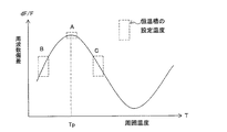
図6はSCカット水晶振動子の周波数温度特性曲線を示す図であり、変曲点の近傍の周
波数温度特性を示している。SCカット水晶振動子の周波数温度特性曲線の極大値の温度
、即ち零温度係数温度(頂点温度Tp)に、恒温槽の温度Tovを設定するのが望ましい
。つまり、図6の周波数温度特性曲線の領域Aに設定することが望ましい。しかし、設定
温度Tovを頂点温度Tpより低温度側の領域Bに設定する場合と、頂点温度Tpより高
温度側の領域Cに設定する場合とでは、恒温槽の内部温度Tovが、周囲温度Taの変化
により図5に示すように僅かに変動した場合に、恒温型圧電発振器の周波数変化の様子が
異なる。
図6は、横軸を周囲温度Tとし、縦軸をSCカット水晶振動子の周波数偏差としたとき
、周囲温度Tの僅かの変化に対するSCカット水晶振動子の周波数変化を示す図である。
恒温槽の内部温度TovをSCカット水晶振動子の頂点温度Tp、図6の領域Aに設定し
た場合は、内部温度Tovが僅かに変動しても恒温型圧電発振器の周波数偏差dF/Fは
、図7の曲線CAのように変化しない。恒温槽の内部温度Tovを頂点温度Tpより低温
側、図6の領域Bに設定した場合は、内部温度Tovが僅かに上昇すると、恒温型圧電発
振器の周波数偏差dF/Fは、図7の曲線CBのように内部温度Tovと共に増加なる。
また、内部温度Tovを頂点温度Tpより高温側、図6の領域Cに設定した場合は、内部
温度Tovが僅かに上昇すると周波数偏差dF/Fは、図7の曲線CCのように内部温度
Tovが僅かに上昇すると、逆に減少する。
逆に、設定温度Tovを一定にした高温槽に、頂点温度TpがばらつくSCカット水晶
振動子を収容して構成した恒温型圧電発振器の周波数偏差の変化は、上記のと同様である
。
FIG. 6 is a diagram showing a frequency-temperature characteristic curve of the SC cut crystal resonator, and shows a frequency-temperature characteristic near the inflection point. It is desirable to set the temperature Tov of the thermostatic chamber to the maximum value of the frequency temperature characteristic curve of the SC cut crystal resonator, that is, the zero temperature coefficient temperature (apex temperature Tp). That is, it is desirable to set in the region A of the frequency temperature characteristic curve of FIG. However, in the case where the set temperature Tov is set in the region B on the lower temperature side than the apex temperature Tp and the case where the set temperature Tov is set in the region C on the higher temperature side than the apex temperature Tp, the internal temperature Tov of the thermostatic bath is the ambient temperature Ta. When the frequency fluctuates slightly as shown in FIG. 5, the frequency change of the constant temperature piezoelectric oscillator is different.
FIG. 6 is a diagram showing a change in frequency of the SC cut crystal resonator with respect to a slight change in the ambient temperature T, where the horizontal axis is the ambient temperature T and the vertical axis is the frequency deviation of the SC cut crystal resonator.
When the internal temperature Tov of the thermostatic chamber is set to the apex temperature Tp of the SC-cut crystal resonator, the region A in FIG. 6, the frequency deviation dF / F of the thermostatic piezoelectric oscillator is obtained even if the internal temperature Tov slightly varies. It does not change as the curve C a of FIG. When the internal temperature Tov of the thermostatic chamber is set in the region B in FIG. 6 that is lower than the apex temperature Tp, when the internal temperature Tov slightly increases, the frequency deviation dF / F of the thermostatic piezoelectric oscillator is the curve in FIG. It becomes increased with an internal temperature Tov as C B.
Further, the high temperature-side internal temperature Tov than the peak temperature Tp, if you set the region C in FIG. 6, the frequency deviation dF / F is the internal temperature Tov slightly increases the internal temperature as indicated by the curve C C of Fig. 7 When Tov increases slightly, it decreases conversely.
On the contrary, the change in frequency deviation of the constant temperature type piezoelectric oscillator configured by accommodating the SC cut crystal resonator in which the apex temperature Tp varies in the high temperature bath in which the set temperature Tov is constant is the same as described above.
図4に示した恒温型圧電発振器の周波数温度特性を検討し直してみた。SCカット水晶
振動子の頂点温度Tpと、恒温槽の設定温度(内部温度)Tovとの温度差(Tp−To
v)を横軸とし、70℃における恒温型圧電発振器の周波数偏差dF/F_70℃と、−
10℃における周波数偏差周波数偏差dF/F_−10℃と、の差(dF/F_70℃−d
F/F_−10℃)を縦軸として、図4に示した周波数温度特性のデータをプロットし直
した図が、図8である。図8より温度差(Tp−Tov)と、周波数偏差の差(dF/F
_70℃−dF/F_−10℃)との間には強い相関があることを見出した。図8は、この
相関を一次関数で近似した例である。図8から周波数偏差の差(dF/F_70℃−dF
/F_−10℃)を補償すれば、恒温槽の設定温度Tovを、SCカット水晶振動子の頂
点温度Tpに合わせ込まなくとも、恒温型圧電発振器の周波数温度特性を所望の安定度内
に調整できることを想致した。
多数のSCカット水晶振動子の頂点温度Tpを測定し、その頂点温度の平均値の温度に
恒温槽の温度Tovを設定する。SCカット水晶振動子個々の頂点温度Tpを測定し、温
度差(Tp−Tov)を求める。温度差(Tp−Tov)を図8の横軸に当てはめると、
横軸より恒温型圧電発振器に生じる周波数偏差の差(dF/F_70℃−dF/F_−10
℃)が推定される。恒温型圧電発振器の周波数温度特性を所望の安定度内に収めるには、
推定された(dF/F_70℃−dF/F_−10℃)を零にすればよい。つまり、恒温型
圧電発振器の発振周波数を−(dF/F_70℃−dF/F_−10℃)だけ補償してやれ
ばよい。
そこで、図8の周波数温度特性補償近似曲線K1の逆特性の逆温度特性補償量近似式を
求め、この逆温度特性補償量近似式に頂点温度Tpと設定内部温度Tovとを入れて周波
数補償量を求め、恒温型圧電発振器の発振周波数に加算してやればよい。
The frequency temperature characteristics of the constant temperature piezoelectric oscillator shown in FIG. 4 were examined again. Temperature difference (Tp-To) between the vertex temperature Tp of the SC-cut crystal resonator and the set temperature (internal temperature) Tov of the thermostatic chamber
v) is the horizontal axis, and the frequency deviation dF / F_70 ° C. of the constant temperature piezoelectric oscillator at 70 ° C., −
Frequency deviation at 10 ° C. Frequency deviation dF / F — −10 ° C. (dF / F — 70 ° C.-d
FIG. 8 is a graph obtained by re-plotting the data of the frequency temperature characteristics shown in FIG. 4 with the vertical axis being F / F_−10 ° C. From FIG. 8, the temperature difference (Tp−Tov) and the frequency deviation difference (dF / F
_70 ° C.-dF / F_-10 ° C.). FIG. 8 is an example in which this correlation is approximated by a linear function. From FIG. 8, the difference in frequency deviation (dF / F_70 ° C.−dF
/ F_-10 ° C), the frequency temperature characteristics of the constant temperature type piezoelectric oscillator can be adjusted within the desired stability without having to adjust the set temperature Tov of the constant temperature bath to the apex temperature Tp of the SC cut crystal resonator. I thought I could do it.
The vertex temperatures Tp of a large number of SC-cut quartz resonators are measured, and the temperature Tov of the thermostatic bath is set to the average temperature of the vertex temperatures. The vertex temperature Tp of each SC cut crystal resonator is measured, and the temperature difference (Tp−Tov) is obtained. When the temperature difference (Tp−Tov) is applied to the horizontal axis of FIG.
Difference in frequency deviation (dF / F_70 ° C.−dF / F_−10) generated in the constant temperature type piezoelectric oscillator from the horizontal axis
° C) is estimated. To keep the frequency temperature characteristics of the constant temperature type piezoelectric oscillator within the desired stability,
The estimated (dF / F_70 ° C.−dF / F_−10 ° C.) may be made zero. That is, it is only necessary to compensate the oscillation frequency of the constant temperature type piezoelectric oscillator by − (dF / F_70 ° C.−dF / F_−10 ° C.).
Therefore, an inverse temperature characteristic compensation amount approximate expression of the inverse characteristic of the frequency temperature characteristic compensation approximate curve K1 in FIG. 8 is obtained, and the apex temperature Tp and the set internal temperature Tov are put into this inverse temperature characteristic compensation amount approximate expression to obtain the frequency compensation amount. Can be obtained and added to the oscillation frequency of the constant temperature piezoelectric oscillator.
図9は、温度差(Tp−Tov)と周波数偏差の差(dF/F_70℃−dF/F_−1
0℃)との関係を三次関数K3で近似した場合であり、図10は五次関数K5で近似した
場合である。関数の次数を上げるほど近似の精度の度合いが上がり、恒温型圧電発振器の
周波数偏差を零に近づけることができるが、回路で関数を実現する際に回路が複雑になる
。
図1に示した周波数温度特性補償量近似式3を、図8〜10に示した一次関数近似式K
1、三次関数近似式K3、五次関数近似式K5の何れかを使って求め、求めた式の逆特性
を逆温度特性補償量近似式4とする。ここで逆特性とは、例えば図8の一次関数近似式K
1がY=αX+β(ここで、X=(Tp−Tov)、Y=dF/F_70℃−dF/F_−
10℃)で表わせるとしたとき、Yを−yに、Xをxに置き換えた式をいう。つまり、y
=−(αX+β)(ここで、x=(Tp−Tov)、y=dF/F_70℃−dF/F_−
10℃)を、Yの逆特性という。三次関数近似式、五次関数近似式についても同様である
。
FIG. 9 shows the difference between temperature difference (Tp−Tov) and frequency deviation (dF / F_70 ° C.−dF / F_−1).
0 ° C.) is approximated by a cubic function K3, and FIG. 10 is approximated by a quintic function K5. The degree of approximation accuracy increases as the order of the function is increased, and the frequency deviation of the constant temperature piezoelectric oscillator can be brought close to zero, but the circuit becomes complicated when the function is realized by the circuit.
The frequency temperature characteristic compensation amount
1 or a cubic function approximate expression K3 or a quintic function approximate expression K5, and the inverse characteristic of the calculated expression is defined as an inverse temperature characteristic compensation amount
1 = Y = αX + β (where X = (Tp−Tov), Y = dF / F_70 ° C.−dF / F_−
10 ° C.) where Y is replaced with -y and X is replaced with x. That is, y
= − (ΑX + β) (where x = (Tp−Tov), y = dF / F_70 ° C.−dF / F_−
10 ° C.) is called the reverse characteristic of Y. The same applies to the cubic function approximate expression and the quintic function approximate expression.
逆温度特性補償量近似式4を多項式で表わしたときの各係数、例えば五次式の場合は、
五次の係数をf5、四次の係数をe5、三次の係数をd5、二次の係数をc5、一次の係
数をb5、定数項をa5として、各係数f5、e5、d5、c5、b5、a5をPC(パ
ーソナルコンピューター)等から、恒温型圧電発振器1のインターフェース回路5に出力
し、演算回路6のメモリに各係数f5、e5、d5、c5、b5、a5を格納する。周波
数電圧制御回路7の補償電圧発生回路7aはメモリに格納された係数f5、e5、d5、
c5、b5、a5に基づいて五次関数の電圧を発生させ、この電圧を電圧可変容量回路7
bに印加する。電圧可変容量回路7bは印加された電圧に応じた容量値を呈し、この容量
値が圧電振動子Y1と直列に接続されているので、圧電振動子Y1と発振回路10とから
なる圧電振動子の発振器周波数を可変する。この周波数可変量は、例えば図10の温度差
(Tp−Tov)に対応する周波数偏差の差(dF/F_70℃−dF/F_−10℃)に
対し負号を付けた周波数変化量であり、温度差(Tp−Tov)により生じる周波数偏差
を零に補償するように動作する。
Each coefficient when the inverse temperature characteristic compensation amount
The fifth order coefficient f 5, fourth order coefficient e 5, third-order coefficients d 5, the secondary of the coefficients c 5, first coefficient a b 5, the constant term as a 5, the
A voltage of a quintic function is generated based on c 5 , b 5 , and a 5 , and this voltage is applied to the voltage variable capacitance circuit 7.
Apply to b. The voltage
温度制御部の設定温度Tovを、圧電振動子の頂点温度Tpの平均値である一定温度に
設定する。頂点温度Tpと設定温度Tovとの温度差による恒温型圧電発振器の周波数温
度特性の周波数偏差を求める。この周波数偏差を、多くの恒温型圧電発振器の周波数温度
特性データから得られた周波数温度特性補償量近似式3に基づき補償する。つまり、周波
数電圧制御回路7に周波数補償用の容量を生成させ、この容量値で前記の周波数偏差を補
償するように機能する恒温型圧電発振器を構成する。
温度制御部の設定温度Tovを一定値に設定し、圧電振動子の頂点温度Tpと設定温度
Tovと入力するだけで、温度差(Tp−Tov)による周波数温度特性の周波数偏差を
、演算回路6が補償電圧発生回路7aに補償電極電圧を発生させ、この電圧で周波数補償
用の容量を生成させて周波数偏差を補償するので、調整工程を自動化でき、個々の温度制
御部の調整を省け、大幅な工数削減となるという効果がある。
また、圧電振動子Y1にSCカット水晶振動子を用いることにより、製造する際のマウ
ント時のストレス(歪)のバラツキ、温度変化による歪、経年変化による歪の変化等が生
じた場合に、他のカットの水晶振動子に比べて周波数変化が少ないという効果がある。
The set temperature Tov of the temperature control unit is set to a constant temperature that is an average value of the apex temperatures Tp of the piezoelectric vibrators. The frequency deviation of the frequency temperature characteristic of the constant temperature piezoelectric oscillator due to the temperature difference between the vertex temperature Tp and the set temperature Tov is obtained. This frequency deviation is compensated based on frequency temperature characteristic compensation amount
By simply setting the set temperature Tov of the temperature controller to a constant value and inputting the apex temperature Tp and the set temperature Tov of the piezoelectric vibrator, the frequency deviation of the frequency temperature characteristic due to the temperature difference (Tp-Tov) is calculated by the
In addition, by using an SC-cut crystal resonator for the piezoelectric resonator Y1, when a variation in stress (strain) during mounting, distortion due to temperature change, strain change due to secular change, etc. has occurred, etc. There is an effect that the frequency change is smaller than that of the crystal resonator of the cut.
図11は、逆温度特性補償量近似式4を表わす一次関数、三次関数、五次関数を示した
式である。但しxはSCカット水晶振動子の頂点温度Tpと高温槽の設定温度Tovの温
度差を表わし、yは周波数温度特性の周波数偏差補償量を表わしている。
周波数温度特性補償量近似式3を一次式多項式で近似することにより、恒温型圧電発振
器の周波数温度特性を満たしつつ、補償電圧発生回路の構成が簡素化でき、且つ温度制御
部の調整工数が大幅に削減できるという効果がある。
また、周波数温度特性補償量近似式3を三次式多項式で近似することにより、補償電圧発
生回路の構成が一次式多項式を用いた場合より複雑になるが、恒温型圧電発振器の周波数
温度特性がより改善でき、且つ温度制御部の調整工数が大幅に削減できるという効果があ
る。
また、周波数温度特性補償量近似式を五次式多項式で近似することにより、補償電圧発
生回路の構成は複雑になるが、恒温型圧電発振器の周波数温度特性が大幅に改善でき、且
つ温度制御部の調整工数が大幅に削減できるという効果がある。
FIG. 11 is an equation showing a linear function, a cubic function, and a quintic function representing the inverse temperature characteristic compensation amount
By approximating the frequency temperature characteristic compensation amount
Further, by approximating the frequency temperature characteristic compensation amount
Further, by approximating the frequency temperature characteristic compensation amount approximation equation with a quintic polynomial, the configuration of the compensation voltage generation circuit becomes complicated, but the frequency temperature characteristic of the constant temperature piezoelectric oscillator can be greatly improved, and the temperature control unit The adjustment man-hour can be greatly reduced.
本発明に係る製造方法は、上記の恒温型圧電発振器の製造方法であって、圧電振動子Y
1の頂点温度Tpを測定する圧電振動子測定工程と、温度制御部8の設定温度Tovを設
定する温度制御部調整工程と、周波数温度特性補償量近似式3に基づいて作成される逆温
度特性補償量近似式4の各係数を求める工程と、この各係数をインターフェース回路5を
介して演算回路6に入力する工程と、演算回路6からの信号により補償電圧発生回路7a
に補償電圧を生成させる工程と、この電圧により電圧可変容量回路7bに容量を生成する
工程と、この容量の容量値により、恒温型圧電発振器の周波数を調整する工程と、を有す
る恒温型圧電発振器の製造方法である。
予め、温度制御部8の設定温度Tovを一定にした多数の恒温型圧電発振器1の周波数
温度特性データを測定して、高温Thにおける周波数偏差dF/F|Thと低温Tlにお
ける周波数偏差dF/F|Tlとの差(dF/F|Th−dF/F|Tl)と、(Tp−
Tov)との関係式、即ち周波数温度特性補償量近似式3を求め、この関係式の逆特性の
逆温度特性補償量近似式4を求めておく。
圧電振動子Y1の頂点温度Tpを測定し、温度制御部8の設定温度Tovを設定し、こ
のデータTp、Tovを入力して、逆温度特性補償量近似式4の各係数を求め、この各係
数を演算回路のメモリに格納する。演算回路8はメモリに格納された各係数に基づき、周
波数電圧制御回路7に補償電圧を発生させ、この電圧により周波数を補償する容量を生成
する。このように、周波数温度特性補償量近似式3を求めておけば、TpとTovの入力
だけで恒温型圧電発振器の調整が完了するので、調整工数を大幅に削減できる製造方法で
ある。
なお、SCカット水晶振動子を例示して説明したが、本願発明は他のカット角を有する
水晶振動子でも実施可能である。
A manufacturing method according to the present invention is a manufacturing method of the above-described constant temperature type piezoelectric oscillator, wherein the piezoelectric vibrator Y
Piezoelectric vibrator measuring step for measuring the apex temperature Tp of 1, temperature control unit adjusting step for setting the set temperature Tov of the
Generating a compensation voltage, generating a capacitance in the voltage
The frequency temperature characteristic data of a large number of constant temperature
Tov), that is, frequency temperature characteristic compensation amount
The apex temperature Tp of the piezoelectric vibrator Y1 is measured, the set temperature Tov of the
Although the SC cut crystal resonator has been described as an example, the present invention can be implemented with a crystal resonator having another cut angle.
1…恒温型圧電発振器、3…周波数温度特性補償量近似式、4…逆温度特性補償量近似式
、Y1…圧電振動子、5…IF回路、6…演算回路、7…周波数電圧制御回路、7a…補
償電圧発生回路、7b…電圧可変容量回路、8…温度制御部、8a…感温素子、8b…発
熱体、8c…温度制御回路、10…発振回路、12…周波数可変入力端子、14…出力周
波数端子
DESCRIPTION OF
Claims (2)
前記圧電振動子を励振する発振回路と、
前記圧電振動子を加熱する発熱体、温度を検知する感温素子、及び前記感温素子の信号に基づき前記発熱体の温度を制御する温度制御回路、を備えている温度制御部と、
前記発振回路の出力信号の周波数偏差を補償するための補償電圧を出力する補償電圧発生回路、ならびに前記補償電圧により容量値が制御される電圧可変容量回路を備えている周波数電圧制御回路と、
メモリと、
を備えている恒温型圧電発振器の製造方法であって、
前記温度制御部を動作させて前記圧電振動子を加熱させた状態で前記前記圧電振動子の所望の温度と前記温度制御部の設定温度との温度差に伴い生じる前記周波数偏差に関わる周波数温度特性データを測定する工程と、
前記周波数電圧制御回路が前記補償電圧を出力するために必要なデータを前記周波数温度特性データから求めると共に、求めた前記データをメモリに格納する工程と、
を含むことを特徴とする恒温型圧電発振器の製造方法。 A piezoelectric vibrator;
An oscillation circuit for exciting the piezoelectric vibrator;
A temperature control unit including a heating element that heats the piezoelectric vibrator, a temperature sensing element that detects temperature, and a temperature control circuit that controls the temperature of the heating element based on a signal from the temperature sensing element;
A compensation voltage generation circuit that outputs a compensation voltage for compensating a frequency deviation of an output signal of the oscillation circuit, and a frequency voltage control circuit including a voltage variable capacitance circuit whose capacitance value is controlled by the compensation voltage;
Memory,
A method of manufacturing a constant temperature piezoelectric oscillator comprising:
Frequency temperature characteristics related to the frequency deviation caused by a temperature difference between a desired temperature of the piezoelectric vibrator and a set temperature of the temperature control section in a state where the temperature control section is operated and the piezoelectric vibrator is heated. Measuring the data;
Obtaining the data necessary for the frequency voltage control circuit to output the compensation voltage from the frequency temperature characteristic data, and storing the obtained data in a memory;
A method of manufacturing a constant temperature piezoelectric oscillator, comprising:
前記周波数温度特性データを測定する工程において、前記所定の温度は、前記零温度係数になる温度であることを特徴とする請求項8に記載の恒温型圧電発振器の製造方法。 The frequency temperature characteristic of the piezoelectric vibrator has a point that becomes a zero temperature coefficient,
9. The method of manufacturing a constant temperature piezoelectric oscillator according to claim 8, wherein, in the step of measuring the frequency temperature characteristic data, the predetermined temperature is a temperature that becomes the zero temperature coefficient.
Priority Applications (4)
| Application Number | Priority Date | Filing Date | Title |
|---|---|---|---|
| JP2010067497A JP5515921B2 (en) | 2010-03-24 | 2010-03-24 | Manufacturing method of constant temperature type piezoelectric oscillator |
| US13/026,375 US8482356B2 (en) | 2010-03-24 | 2011-02-14 | Constant-temperature piezoelectric oscillator and method of manufacturing the same |
| CN201110070549.4A CN102201787B (en) | 2010-03-24 | 2011-03-23 | Constant-temperature piezoelectric oscillator and method of manufacturing the same |
| US13/857,437 US9007134B2 (en) | 2010-03-24 | 2013-04-05 | Constant-temperature piezoelectric oscillator and method of manufacturing the same |
Applications Claiming Priority (1)
| Application Number | Priority Date | Filing Date | Title |
|---|---|---|---|
| JP2010067497A JP5515921B2 (en) | 2010-03-24 | 2010-03-24 | Manufacturing method of constant temperature type piezoelectric oscillator |
Publications (3)
| Publication Number | Publication Date |
|---|---|
| JP2011205166A JP2011205166A (en) | 2011-10-13 |
| JP2011205166A5 JP2011205166A5 (en) | 2013-05-09 |
| JP5515921B2 true JP5515921B2 (en) | 2014-06-11 |
Family
ID=44655721
Family Applications (1)
| Application Number | Title | Priority Date | Filing Date |
|---|---|---|---|
| JP2010067497A Expired - Fee Related JP5515921B2 (en) | 2010-03-24 | 2010-03-24 | Manufacturing method of constant temperature type piezoelectric oscillator |
Country Status (3)
| Country | Link |
|---|---|
| US (2) | US8482356B2 (en) |
| JP (1) | JP5515921B2 (en) |
| CN (1) | CN102201787B (en) |
Families Citing this family (36)
| Publication number | Priority date | Publication date | Assignee | Title |
|---|---|---|---|---|
| JP5515921B2 (en) * | 2010-03-24 | 2014-06-11 | セイコーエプソン株式会社 | Manufacturing method of constant temperature type piezoelectric oscillator |
| JP5966577B2 (en) * | 2012-05-08 | 2016-08-10 | セイコーエプソン株式会社 | Temperature compensation circuit, circuit device, electronic device and adjustment method |
| JP6123979B2 (en) * | 2012-05-23 | 2017-05-10 | セイコーエプソン株式会社 | Oscillator and electronic device |
| JP6060011B2 (en) * | 2013-03-12 | 2017-01-11 | 京セラクリスタルデバイス株式会社 | Oscillator |
| JP2014197751A (en) * | 2013-03-29 | 2014-10-16 | セイコーエプソン株式会社 | Oscillator, electronic apparatus and mobile object |
| JP6350793B2 (en) * | 2013-12-25 | 2018-07-04 | セイコーエプソン株式会社 | OSCILLATOR CIRCUIT, OSCILLATOR, ELECTRONIC DEVICE, MOBILE BODY, AND OSCILLATOR MANUFACTURING METHOD |
| JP6177155B2 (en) * | 2014-02-10 | 2017-08-09 | ソニーセミコンダクタソリューションズ株式会社 | Oscillator circuit and frequency synthesizer |
| CN104506140A (en) * | 2014-11-04 | 2015-04-08 | 中国科学院上海光学精密机械研究所 | Constant temperature crystal oscillator high-precision frequency control device and control method thereof |
| JP2016144128A (en) * | 2015-02-04 | 2016-08-08 | セイコーエプソン株式会社 | Oscillator, electronic apparatus, and mobile body |
| JP2017139682A (en) * | 2016-02-05 | 2017-08-10 | セイコーエプソン株式会社 | Vibration piece, manufacturing method for the same, oscillator, electronic apparatus, movable body, and base station |
| US10149193B2 (en) | 2016-06-15 | 2018-12-04 | At&T Intellectual Property I, L.P. | Method and apparatus for dynamically managing network resources |
| US10284730B2 (en) | 2016-11-01 | 2019-05-07 | At&T Intellectual Property I, L.P. | Method and apparatus for adaptive charging and performance in a software defined network |
| US10454836B2 (en) | 2016-11-01 | 2019-10-22 | At&T Intellectual Property I, L.P. | Method and apparatus for dynamically adapting a software defined network |
| US10505870B2 (en) | 2016-11-07 | 2019-12-10 | At&T Intellectual Property I, L.P. | Method and apparatus for a responsive software defined network |
| US10469376B2 (en) | 2016-11-15 | 2019-11-05 | At&T Intellectual Property I, L.P. | Method and apparatus for dynamic network routing in a software defined network |
| KR102610822B1 (en) * | 2016-11-30 | 2023-12-06 | 삼성전자주식회사 | Circuit for controlling oscillator and apparatus including the same |
| US10039006B2 (en) | 2016-12-05 | 2018-07-31 | At&T Intellectual Property I, L.P. | Method and system providing local data breakout within mobility networks |
| US10264075B2 (en) * | 2017-02-27 | 2019-04-16 | At&T Intellectual Property I, L.P. | Methods, systems, and devices for multiplexing service information from sensor data |
| US10469286B2 (en) | 2017-03-06 | 2019-11-05 | At&T Intellectual Property I, L.P. | Methods, systems, and devices for managing client devices using a virtual anchor manager |
| US10819606B2 (en) | 2017-04-27 | 2020-10-27 | At&T Intellectual Property I, L.P. | Method and apparatus for selecting processing paths in a converged network |
| US10212289B2 (en) | 2017-04-27 | 2019-02-19 | At&T Intellectual Property I, L.P. | Method and apparatus for managing resources in a software defined network |
| US10673751B2 (en) | 2017-04-27 | 2020-06-02 | At&T Intellectual Property I, L.P. | Method and apparatus for enhancing services in a software defined network |
| US10749796B2 (en) | 2017-04-27 | 2020-08-18 | At&T Intellectual Property I, L.P. | Method and apparatus for selecting processing paths in a software defined network |
| US10382903B2 (en) | 2017-05-09 | 2019-08-13 | At&T Intellectual Property I, L.P. | Multi-slicing orchestration system and method for service and/or content delivery |
| US10257668B2 (en) | 2017-05-09 | 2019-04-09 | At&T Intellectual Property I, L.P. | Dynamic network slice-switching and handover system and method |
| US10070344B1 (en) | 2017-07-25 | 2018-09-04 | At&T Intellectual Property I, L.P. | Method and system for managing utilization of slices in a virtual network function environment |
| US10425084B2 (en) * | 2017-10-03 | 2019-09-24 | Murata Manufacturing Co., Ltd. | Oven controlled MEMS oscillator and system and method for calibrating the same |
| US10104548B1 (en) | 2017-12-18 | 2018-10-16 | At&T Intellectual Property I, L.P. | Method and apparatus for dynamic instantiation of virtual service slices for autonomous machines |
| CN110336535A (en) * | 2019-06-12 | 2019-10-15 | Oppo广东移动通信有限公司 | A kind of crystal oscillator calibration method, device, terminal device and storage medium |
| DE112020006422T5 (en) | 2020-03-19 | 2022-11-03 | Murata Manufacturing Co., Ltd. | CRYSTAL MOBILIZING ELEMENT, CRYSTAL MOBILE AND CRYSTAL OSCILLATOR |
| CN111490781B (en) * | 2020-04-22 | 2023-05-26 | 中国科学院国家授时中心 | Time keeping method for controlling voltage-controlled crystal oscillator based on temperature variation difference |
| CN111884589B (en) * | 2020-08-26 | 2021-11-05 | 硅谷数模(苏州)半导体有限公司 | Method and device for determining temperature compensation parameters of frequency source |
| CN113285671B (en) * | 2021-05-14 | 2023-08-22 | 广东虹勤通讯技术有限公司 | Method and device for calibrating frequency-temperature compensation curve of digital crystal oscillator |
| CN114035024B (en) * | 2021-10-26 | 2023-11-14 | 深圳市兴威帆电子技术有限公司 | Real-time clock chip testing system and method |
| CN114594807B (en) * | 2022-03-07 | 2023-02-28 | 黄山奥仪电器有限公司 | Constant temperature control system based on VTI |
| CN115001483B (en) * | 2022-07-15 | 2022-10-28 | 深圳市英特瑞半导体科技有限公司 | Adaptive temperature change clock module and adaptive temperature change method |
Family Cites Families (18)
| Publication number | Priority date | Publication date | Assignee | Title |
|---|---|---|---|---|
| US2007A (en) * | 1841-03-16 | Improvement in the mode of harvesting grain | ||
| JPS6355614A (en) | 1986-08-27 | 1988-03-10 | Nippon Telegr & Teleph Corp <Ntt> | Timer control system for information processor |
| JPS6355614U (en) * | 1986-09-29 | 1988-04-14 | ||
| JPS6482809A (en) * | 1987-09-25 | 1989-03-28 | Kinseki Ltd | Digital temperature compensated crystal oscillator |
| JPH01248806A (en) * | 1988-03-30 | 1989-10-04 | Nec Corp | Constant temperature bath type piezoelectric oscillator |
| JPH0296406A (en) * | 1988-09-30 | 1990-04-09 | Nippon Dempa Kogyo Co Ltd | Temperature compensation crystal oscillator |
| GB2233513A (en) * | 1989-06-09 | 1991-01-09 | Philips Electronic Associated | Oscillators |
| JP3272633B2 (en) | 1997-04-30 | 2002-04-08 | キンセキ株式会社 | Thermostat type piezoelectric oscillator |
| JP4070139B2 (en) * | 2002-08-28 | 2008-04-02 | 旭化成エレクトロニクス株式会社 | Approximate nth order function generator and temperature compensated crystal oscillation circuit |
| JP2005124022A (en) * | 2003-10-20 | 2005-05-12 | Matsushita Electric Ind Co Ltd | Function generating circuit |
| US7253694B2 (en) | 2004-07-15 | 2007-08-07 | C-Mac Quartz Crystals, Limited | Temperature compensated oven controlled crystal oscillator |
| JP4796414B2 (en) | 2006-03-14 | 2011-10-19 | 日本電波工業株式会社 | Crystal oscillator |
| CN100527597C (en) * | 2006-03-28 | 2009-08-12 | 青岛硅盛微电子有限公司 | High precision temperature compensation crystal oscillator |
| US7482889B2 (en) * | 2006-06-28 | 2009-01-27 | Cts Corporation | Apparatus and method of temperature compensating an ovenized oscillator |
| EP2045616B1 (en) * | 2006-07-21 | 2013-09-11 | Mitsubishi Electric Corporation | Modulation signal generation circuit, transmission/reception module, and radar device |
| US7466209B2 (en) * | 2007-01-05 | 2008-12-16 | Sirf Technology, Inc. | System and method for providing temperature correction in a crystal oscillator |
| JP2009200888A (en) * | 2008-02-22 | 2009-09-03 | Seiko Instruments Inc | Mems oscillator |
| JP5515921B2 (en) * | 2010-03-24 | 2014-06-11 | セイコーエプソン株式会社 | Manufacturing method of constant temperature type piezoelectric oscillator |
-
2010
- 2010-03-24 JP JP2010067497A patent/JP5515921B2/en not_active Expired - Fee Related
-
2011
- 2011-02-14 US US13/026,375 patent/US8482356B2/en active Active
- 2011-03-23 CN CN201110070549.4A patent/CN102201787B/en active Active
-
2013
- 2013-04-05 US US13/857,437 patent/US9007134B2/en active Active
Also Published As
| Publication number | Publication date |
|---|---|
| CN102201787A (en) | 2011-09-28 |
| US8482356B2 (en) | 2013-07-09 |
| US20110234328A1 (en) | 2011-09-29 |
| US9007134B2 (en) | 2015-04-14 |
| CN102201787B (en) | 2015-01-14 |
| JP2011205166A (en) | 2011-10-13 |
| US20140070892A1 (en) | 2014-03-13 |
Similar Documents
| Publication | Publication Date | Title |
|---|---|---|
| JP5515921B2 (en) | Manufacturing method of constant temperature type piezoelectric oscillator | |
| JP4738409B2 (en) | Temperature compensated thermostatic chamber controlled crystal oscillator | |
| US7403078B2 (en) | Temperature compensated crystal oscillator | |
| JP2001267847A (en) | Temperature compensated crystal oscillator and method for compensating temperature or the oscillator | |
| JP2011114403A (en) | Temperature compensation method for piezoelectric oscillator, and piezoelectric oscillator | |
| JP5218169B2 (en) | Piezoelectric oscillator and method for measuring ambient temperature of this piezoelectric oscillator | |
| JP5429653B2 (en) | Oscillator and method of manufacturing oscillator | |
| JP5205827B2 (en) | Oscillation frequency control method and oscillator | |
| TWI599162B (en) | Oscillating device and electronic apparatus having the same | |
| WO1995011456A1 (en) | Frequency counter and frequency counting method | |
| CN112385055B (en) | Determination and application of voltage to a piezoelectric actuator | |
| JP2002076774A (en) | Method for regulating temperature compensated oscillator | |
| JP5082988B2 (en) | Method for adjusting temperature compensated piezoelectric oscillator and temperature compensated piezoelectric oscillator adjusted by the method | |
| JP2011234094A (en) | Piezoelectric oscillator, manufacturing method of piezoelectric oscillator and temperature compensation method of piezoelectric oscillator | |
| CN110198155A (en) | A kind of digital temperature compensation crystal oscillator | |
| JP2005347929A (en) | Temperature compensating crystal oscillator and its adjustment method | |
| JPH08237030A (en) | Temperature compensation device for crystal oscillation circuit | |
| JP2002204127A (en) | Method and device for adjusting temperature compensating crystal oscillator | |
| JP2014230201A (en) | Temperature control circuit, oven-controlled piezoelectric oscillator and temperature control method | |
| JP3211134B2 (en) | Calculation method of oscillation frequency of crystal unit | |
| US11799423B2 (en) | Method of building oscillator frequency adjustment lookup table and associated transceiver | |
| RU2726170C1 (en) | Generator with dynamic heating of saw resonator thermostat | |
| JP5213845B2 (en) | Temperature compensated crystal oscillator | |
| RU2669055C1 (en) | System and method for operating mechanical resonator in electronic oscillator | |
| US20230231519A1 (en) | Oscillator circuit and temperature compensation method for oscillator circuit |
Legal Events
| Date | Code | Title | Description |
|---|---|---|---|
| A521 | Request for written amendment filed |
Free format text: JAPANESE INTERMEDIATE CODE: A523 Effective date: 20130322 |
|
| A621 | Written request for application examination |
Free format text: JAPANESE INTERMEDIATE CODE: A621 Effective date: 20130322 |
|
| A977 | Report on retrieval |
Free format text: JAPANESE INTERMEDIATE CODE: A971007 Effective date: 20131205 |
|
| A131 | Notification of reasons for refusal |
Free format text: JAPANESE INTERMEDIATE CODE: A131 Effective date: 20131217 |
|
| A521 | Request for written amendment filed |
Free format text: JAPANESE INTERMEDIATE CODE: A523 Effective date: 20140210 |
|
| TRDD | Decision of grant or rejection written | ||
| A01 | Written decision to grant a patent or to grant a registration (utility model) |
Free format text: JAPANESE INTERMEDIATE CODE: A01 Effective date: 20140304 |
|
| A61 | First payment of annual fees (during grant procedure) |
Free format text: JAPANESE INTERMEDIATE CODE: A61 Effective date: 20140317 |
|
| R150 | Certificate of patent or registration of utility model |
Ref document number: 5515921 Country of ref document: JP Free format text: JAPANESE INTERMEDIATE CODE: R150 |
|
| S531 | Written request for registration of change of domicile |
Free format text: JAPANESE INTERMEDIATE CODE: R313531 |
|
| R350 | Written notification of registration of transfer |
Free format text: JAPANESE INTERMEDIATE CODE: R350 |
|
| LAPS | Cancellation because of no payment of annual fees |