JP5513018B2 - Peripheral device and image reading device - Google Patents
Peripheral device and image reading device Download PDFInfo
- Publication number
- JP5513018B2 JP5513018B2 JP2009143655A JP2009143655A JP5513018B2 JP 5513018 B2 JP5513018 B2 JP 5513018B2 JP 2009143655 A JP2009143655 A JP 2009143655A JP 2009143655 A JP2009143655 A JP 2009143655A JP 5513018 B2 JP5513018 B2 JP 5513018B2
- Authority
- JP
- Japan
- Prior art keywords
- information processing
- control
- file
- processing apparatus
- usb
- Prior art date
- Legal status (The legal status is an assumption and is not a legal conclusion. Google has not performed a legal analysis and makes no representation as to the accuracy of the status listed.)
- Active
Links
- 230000002093 peripheral effect Effects 0.000 title claims description 208
- 230000010365 information processing Effects 0.000 claims description 218
- 238000012545 processing Methods 0.000 claims description 76
- 238000000034 method Methods 0.000 claims description 62
- 230000008569 process Effects 0.000 claims description 48
- 230000006870 function Effects 0.000 claims description 44
- 238000004891 communication Methods 0.000 claims description 31
- 238000009434 installation Methods 0.000 claims description 24
- 230000004044 response Effects 0.000 claims description 14
- 239000000725 suspension Substances 0.000 claims description 2
- 239000000872 buffer Substances 0.000 description 88
- 238000012546 transfer Methods 0.000 description 66
- 238000010586 diagram Methods 0.000 description 27
- 230000005540 biological transmission Effects 0.000 description 16
- 238000012360 testing method Methods 0.000 description 13
- 238000007639 printing Methods 0.000 description 10
- 230000004913 activation Effects 0.000 description 7
- 230000015572 biosynthetic process Effects 0.000 description 7
- 238000012544 monitoring process Methods 0.000 description 7
- 230000007704 transition Effects 0.000 description 7
- 230000008859 change Effects 0.000 description 4
- 239000000284 extract Substances 0.000 description 4
- 238000004590 computer program Methods 0.000 description 3
- 238000001514 detection method Methods 0.000 description 3
- 241000700605 Viruses Species 0.000 description 2
- 238000012790 confirmation Methods 0.000 description 2
- 208000015181 infectious disease Diseases 0.000 description 2
- 238000003780 insertion Methods 0.000 description 2
- 230000037431 insertion Effects 0.000 description 2
- 230000005856 abnormality Effects 0.000 description 1
- 230000003213 activating effect Effects 0.000 description 1
- 230000006399 behavior Effects 0.000 description 1
- 238000006243 chemical reaction Methods 0.000 description 1
- 230000006835 compression Effects 0.000 description 1
- 238000007906 compression Methods 0.000 description 1
- 238000005516 engineering process Methods 0.000 description 1
- 239000012464 large buffer Substances 0.000 description 1
- 230000000737 periodic effect Effects 0.000 description 1
- 238000003825 pressing Methods 0.000 description 1
- 238000004904 shortening Methods 0.000 description 1
Images


Classifications
-
- H—ELECTRICITY
- H04—ELECTRIC COMMUNICATION TECHNIQUE
- H04N—PICTORIAL COMMUNICATION, e.g. TELEVISION
- H04N1/00—Scanning, transmission or reproduction of documents or the like, e.g. facsimile transmission; Details thereof
- H04N1/00962—Input arrangements for operating instructions or parameters, e.g. updating internal software
-
- G—PHYSICS
- G03—PHOTOGRAPHY; CINEMATOGRAPHY; ANALOGOUS TECHNIQUES USING WAVES OTHER THAN OPTICAL WAVES; ELECTROGRAPHY; HOLOGRAPHY
- G03G—ELECTROGRAPHY; ELECTROPHOTOGRAPHY; MAGNETOGRAPHY
- G03G15/00—Apparatus for electrographic processes using a charge pattern
- G03G15/50—Machine control of apparatus for electrographic processes using a charge pattern, e.g. regulating differents parts of the machine, multimode copiers, microprocessor control
- G03G15/5075—Remote control machines, e.g. by a host
-
- H—ELECTRICITY
- H04—ELECTRIC COMMUNICATION TECHNIQUE
- H04N—PICTORIAL COMMUNICATION, e.g. TELEVISION
- H04N1/00—Scanning, transmission or reproduction of documents or the like, e.g. facsimile transmission; Details thereof
- H04N1/00127—Connection or combination of a still picture apparatus with another apparatus, e.g. for storage, processing or transmission of still picture signals or of information associated with a still picture
- H04N1/00204—Connection or combination of a still picture apparatus with another apparatus, e.g. for storage, processing or transmission of still picture signals or of information associated with a still picture with a digital computer or a digital computer system, e.g. an internet server
- H04N1/00236—Connection or combination of a still picture apparatus with another apparatus, e.g. for storage, processing or transmission of still picture signals or of information associated with a still picture with a digital computer or a digital computer system, e.g. an internet server using an image reading or reproducing device, e.g. a facsimile reader or printer, as a local input to or local output from a computer
-
- H—ELECTRICITY
- H04—ELECTRIC COMMUNICATION TECHNIQUE
- H04N—PICTORIAL COMMUNICATION, e.g. TELEVISION
- H04N1/00—Scanning, transmission or reproduction of documents or the like, e.g. facsimile transmission; Details thereof
- H04N1/00912—Arrangements for controlling a still picture apparatus or components thereof not otherwise provided for
- H04N1/00938—Software related arrangements, e.g. loading applications
-
- H—ELECTRICITY
- H04—ELECTRIC COMMUNICATION TECHNIQUE
- H04N—PICTORIAL COMMUNICATION, e.g. TELEVISION
- H04N2201/00—Indexing scheme relating to scanning, transmission or reproduction of documents or the like, and to details thereof
- H04N2201/0008—Connection or combination of a still picture apparatus with another apparatus
- H04N2201/0034—Details of the connection, e.g. connector, interface
- H04N2201/0037—Topological details of the connection
- H04N2201/0041—Point to point
-
- H—ELECTRICITY
- H04—ELECTRIC COMMUNICATION TECHNIQUE
- H04N—PICTORIAL COMMUNICATION, e.g. TELEVISION
- H04N2201/00—Indexing scheme relating to scanning, transmission or reproduction of documents or the like, and to details thereof
- H04N2201/0008—Connection or combination of a still picture apparatus with another apparatus
- H04N2201/0034—Details of the connection, e.g. connector, interface
- H04N2201/0048—Type of connection
- H04N2201/0049—By wire, cable or the like
-
- H—ELECTRICITY
- H04—ELECTRIC COMMUNICATION TECHNIQUE
- H04N—PICTORIAL COMMUNICATION, e.g. TELEVISION
- H04N2201/00—Indexing scheme relating to scanning, transmission or reproduction of documents or the like, and to details thereof
- H04N2201/0008—Connection or combination of a still picture apparatus with another apparatus
- H04N2201/007—Selecting or switching between a still picture apparatus or function and another apparatus or function
-
- H—ELECTRICITY
- H04—ELECTRIC COMMUNICATION TECHNIQUE
- H04N—PICTORIAL COMMUNICATION, e.g. TELEVISION
- H04N2201/00—Indexing scheme relating to scanning, transmission or reproduction of documents or the like, and to details thereof
- H04N2201/0008—Connection or combination of a still picture apparatus with another apparatus
- H04N2201/0074—Arrangements for the control of a still picture apparatus by the connected apparatus
- H04N2201/0075—Arrangements for the control of a still picture apparatus by the connected apparatus by a user operated remote control device, e.g. receiving instructions from a user via a computer terminal or mobile telephone handset
Landscapes
- Engineering & Computer Science (AREA)
- Multimedia (AREA)
- Signal Processing (AREA)
- General Engineering & Computer Science (AREA)
- Computing Systems (AREA)
- Microelectronics & Electronic Packaging (AREA)
- Physics & Mathematics (AREA)
- General Physics & Mathematics (AREA)
- Stored Programmes (AREA)
- Facsimiles In General (AREA)
- Accessory Devices And Overall Control Thereof (AREA)
- Storing Facsimile Image Data (AREA)
Description
本発明は、イメージスキャナ、プリンタまたは複合機などの周辺装置に関する。 The present invention relates to a peripheral device such as an image scanner, a printer, or a multifunction peripheral.
イメージスキャナ、プリンタまたは複合機などの周辺装置は広く普及している。これらの周辺装置に接続するインターフェースとして、シリアルインタフェース、パラレルインタフェース、USB、IEEE1394、LANなどが知られている。 Peripheral devices such as image scanners, printers, and multifunction peripherals are widely used. As an interface for connecting to these peripheral devices, a serial interface, a parallel interface, USB, IEEE 1394, LAN, and the like are known.
ところで、周辺装置をコンピュータ上で使用できるようにするためには、その周辺装置用のデバイスドライバやアプリケーションソフトウエアをインストールしなければならない(特許文献1)。 Incidentally, in order to be able to use a peripheral device on a computer, it is necessary to install a device driver and application software for the peripheral device (Patent Document 1).
しかし、デバイスドライバやアプリケーションソフトウエアをインストールすることが制限されているコンピュータが存在する。この制限はセキュリティ対策で課されることが多い。例えば、マイクロソフトウインドウズ(登録商標)等のオペレーティングシステム(OS)では、管理者権限を有しているユーザのみがデバイスドライバをインストールできる。したがって、一般ユーザはデバイスドライバやアプリケーションソフトウエアをインストールできないため、周辺装置を利用できなくなってしまう。このような状況は、外出先のコンピュータを使用する場合に度々発生することが予想される。 However, there are computers that are restricted from installing device drivers and application software. This restriction is often imposed by security measures. For example, in an operating system (OS) such as Microsoft Windows (registered trademark), only a user having administrator authority can install a device driver. Therefore, since a general user cannot install a device driver or application software, the peripheral device cannot be used. Such a situation is expected to occur frequently when using a computer outside the office.
また、従来は、管理者権限を持つユーザであっても、画像読み取り装置を接続する前に、予め、デバイスドライバをインストールしておかなければならなかった。すなわち、従来は、デバイスドライバをコンピュータにインストールしていない状態で、周辺装置を利用することができなかった。 Conventionally, even a user having administrator authority has to install a device driver in advance before connecting the image reading apparatus. That is, conventionally, a peripheral device cannot be used without a device driver installed in the computer.
さらに、デバイスドライバは、一般に、CD−ROMにより頒布されている。よって、このCD−ROMを用意しなければ、デバイスドライバをインストールすることができなかった。例えば、CD−ROMを紛失してしまうと、デバイスドライバをインストールすることができなかった。インターネットを介してデバイスドライバを入手できるケースもあるが、そのためにインターネットに接続できる環境が必要である。また、デバイスドライバを提供しているWEBサイトのURLや、周辺装置の種類や名称を正確に把握して入力しなければならず、面倒であった。 Furthermore, the device driver is generally distributed by a CD-ROM. Therefore, the device driver cannot be installed unless this CD-ROM is prepared. For example, if the CD-ROM is lost, the device driver cannot be installed. In some cases, the device driver can be obtained via the Internet. For this reason, an environment capable of connecting to the Internet is required. In addition, it is troublesome because it is necessary to accurately grasp and input the URL of the WEB site providing the device driver and the type and name of the peripheral device.
本発明の目的は、デバイスドライバやソフトウエアをコンピュータにインストールすることなく、周辺装置を利用可能とすることである。また、いくつかの観点での本発明の他の目的は、デバイスドライバやソフトウエアをコンピュータにインストールすることなく、画像読取装置により比較的に大きな画像も読取可能とすることである。また、他のいくつかの観点での本発明の他の目的は、情報処理装置(PC)がデバイスドライバをインストール済みであるか否かに応じて、周辺装置の動作モードを選択する制御を可能とすることである。 An object of the present invention is to make it possible to use a peripheral device without installing a device driver or software in a computer. Another object of the present invention from several viewpoints is to enable a relatively large image to be read by an image reading apparatus without installing a device driver or software in the computer. Another object of the present invention in other aspects is to control the operation mode of the peripheral device depending on whether or not the information processing apparatus (PC) has installed the device driver. It is to do.
本発明は、情報処理装置からの情報に基づいて所定の処理が実行される周辺装置であって、
前記所定の処理を制御する制御プログラム、及び前記周辺装置を制御するための制御ファイルを記憶する記憶手段と、
前記情報処理装置に対して前記記憶手段の前記制御プログラムを送信する通信手段と、
前記情報処理装置の前記制御プログラムの実行において前記記憶手段内の前記制御ファイルに書き込まれた指示情報に基づいて前記周辺装置の動作を制御する制御手段と
を備え、
前記記憶手段は、前記制御プログラム及び前記制御ファイルが記憶されている書き込み禁止又は書き込み不可能な第1メモリ領域と、前記情報処理装置から認識可能な第2メモリ領域とを有し、
前記制御プログラム及び前記制御ファイルを前記第1メモリ領域から前記第2メモリ領域に複製して、前記情報処理装置が前記第2メモリ領域内の前記制御プログラムを実行して前記情報処理装置から前記制御ファイルに書き込まれる前記指示情報に基づいて前記制御手段が前記周辺装置の動作を制御することを特徴とする。
The present invention is a peripheral device in which a predetermined process is executed based on information from an information processing device,
Storage means for storing a control program for controlling the predetermined processing and a control file for controlling the peripheral device;
Communication means for transmitting the control program of the storage means to the information processing apparatus;
Control means for controlling operation of the peripheral device based on instruction information written in the control file in the storage means in execution of the control program of the information processing apparatus;
With
The storage means includes a first memory area in which the control program and the control file are stored, a write-inhibited or non-writable first memory area, and a second memory area recognizable from the information processing apparatus,
The control program and the control file are copied from the first memory area to the second memory area, and the information processing apparatus executes the control program in the second memory area to execute the control from the information processing apparatus. The control means controls the operation of the peripheral device based on the instruction information written in the file .
本発明によれば、周辺装置を制御するためのプログラムを情報処理装置に保存していなくても周辺装置を情報処理装置から利用可能となる。 According to the present invention, the peripheral device can be used from the information processing device even if the program for controlling the peripheral device is not stored in the information processing device.
以下に本発明の一実施形態を示す。以下で説明される個別の実施形態は、本発明の上位概念、中位概念および下位概念など種々の概念を理解するために役立つであろう。また、本発明の技術的範囲は、特許請求の範囲によって確定されるのであって、以下の個別の実施形態によって限定されるわけではない。 An embodiment of the present invention is shown below. The individual embodiments described below will help to understand various concepts, such as the superordinate concept, intermediate concept and subordinate concept of the present invention. Further, the technical scope of the present invention is determined by the scope of the claims, and is not limited by the following individual embodiments.
[観点1]
情報処理装置からの情報に基づいて所定の処理が実行される周辺装置であって、前記所定の処理を制御するプログラムを記憶し、また前記周辺装置を制御するためのデータを記憶する記憶手段と、
前記情報処理装置に対して前記記憶手段の前記プログラムを送信する通信手段と、
前記情報処理装置の前記プログラムの実行において前記記憶手段に書き込まれた指示情報に基づいて前記周辺装置の動作を制御する制御手段と
を備えていることを特徴とする周辺装置。
[Viewpoint 1]
A peripheral device for executing predetermined processing based on information from the information processing device, storing a program for controlling the predetermined processing, and storing means for storing data for controlling the peripheral device; ,
Communication means for transmitting the program in the storage means to the information processing apparatus;
A peripheral device comprising: control means for controlling the operation of the peripheral device based on instruction information written in the storage means in execution of the program of the information processing apparatus.
観点1によれば、前記周辺装置を制御するためのプログラムを情報処理装置にインストールしていなくても周辺装置を情報処理装置から利用可能となる。そのため、プログラムを入手していないユーザであっても周辺装置を利用できるようになる。また、必要なソフトウエアが周辺装置に記憶されているため、CD−ROMの紛失による使用不可といった問題からも開放されよう。 According to the first aspect, even if a program for controlling the peripheral device is not installed in the information processing device, the peripheral device can be used from the information processing device. Therefore, even a user who has not obtained a program can use the peripheral device. Further, since necessary software is stored in the peripheral device, it will be freed from the problem that the CD-ROM cannot be used due to loss.
[観点2]
前記記憶手段は前記プログラムを記憶するRAMを含むことを特徴とする観点1記載の周辺装置。
[Viewpoint 2]
2. The peripheral device according to
このように、観点2によれば、容易にアクセスできる周辺装置のRAMから制御プログラムを利用できるようになる。 Thus, according to the second aspect, the control program can be used from the RAM of the peripheral device that can be easily accessed.
[観点3]
前記記憶手段は、前記プログラムを記憶するROM又は不揮発性メモリを含み、前記RAMは前記指示情報を記憶し、前記制御手段は、前記周辺装置に前記情報処理装置が接続されると前記プログラムを前記RAMに記憶し、前記通信手段は、前記RAMから前記プログラムを前記情報処理装置に送信することを特徴とする観点2記載の周辺装置。
[Viewpoint 3]
The storage means includes a ROM or nonvolatile memory for storing the program, the RAM stores the instruction information, and the control means stores the program when the information processing apparatus is connected to the peripheral device. 3. The peripheral device according to
このように観点3によれば、プログラムをROMや不揮発性メモリに保持することで誤消去からの保護が容易となり、前記プログラムの実行による情報処理装置からの指示情報を、RAMを介して容易に受け取ることが可能となる。従来であれば何らかのデバイスドライバが制御コマンドなどを送信していたのに対して、観点3の周辺装置では制御コマンドなどが周辺装置のRAMに書き込まれるので、間接的に周辺装置を制御できるようになる。 As described above, according to the third aspect, it is easy to protect against erroneous erasure by holding the program in the ROM or the non-volatile memory. It becomes possible to receive. In the past, some device driver sent a control command or the like, but in the peripheral device of viewpoint 3, since the control command or the like is written in the RAM of the peripheral device, the peripheral device can be controlled indirectly. Become.
[観点4]
制御手段は、前記記憶手段の前記RAMをUSBディスクドライブとして前記情報処理装置に認識させるための情報を前記通信手段により情報処理装置へ送信することを特徴とする観点2記載の周辺装置。
[Viewpoint 4]
The peripheral device according to
このように観点4によれば、RAMを読み書き可能なUSBディスクデバイスとして情報処理装置に認識させることで、周辺装置を例えば画像読み取り装置や印刷装置として認識させる必要がなくなる。よって、OSからデバイスドライバのインストールを要求されることもない。 As described above, according to the fourth aspect, by causing the information processing apparatus to recognize the RAM as a readable / writable USB disk device, it is unnecessary to recognize the peripheral device as, for example, an image reading apparatus or a printing apparatus. Therefore, installation of a device driver is not requested from the OS.
[観点5]
前記周辺装置は外部記憶装置として動作する第1動作モードと、所定の処理を実行する処理装置として動作する第2動作モードとを有し、前記制御手段は前記第1動作モードと前記第2動作モードとのいずれか一方を選択する選択手段を備えていることを特徴とする観点2に記載の周辺装置。
[Viewpoint 5]
The peripheral device has a first operation mode that operates as an external storage device, and a second operation mode that operates as a processing device that executes a predetermined process, and the control means includes the first operation mode and the second operation mode. The peripheral device according to
このように観点5によれば、外部記憶装置として周辺装置を情報処理装置に認識させる動作モードと、周辺装置を画像読み取り装置や印刷装置として認識させるモードとを使い分けることができる。 As described above, according to the fifth aspect, the operation mode in which the information processing device recognizes the peripheral device as the external storage device and the mode in which the peripheral device is recognized as the image reading device or the printing device can be used properly.
[観点6]
前記選択手段は、前記周辺装置に設けられる手動スイッチにより前記第1動作モードまたは前記第2動作モードを切り替えるものであることを特徴とする観点5に記載の周辺装置。
[Viewpoint 6]
6. The peripheral device according to aspect 5, wherein the selection unit is configured to switch the first operation mode or the second operation mode by a manual switch provided in the peripheral device.
このように観点6によれば、ユーザは簡単な手の操作でスイッチを切り替えて動作モードの選択を確定させてから周辺装置を使用することができる。 As described above, according to the viewpoint 6, the user can use the peripheral device after confirming the selection of the operation mode by switching the switch with a simple hand operation.
[観点7]
前記プログラムは、前記情報処理装置への前記周辺装置の接続に応じて、前記情報処理装置によって前記通信手段を介して前記記憶手段から前記情報処理装置にロードされることを特徴とする観点1ないし6のいずれかに記載の周辺装置。
[Viewpoint 7]
The program is loaded from the storage unit to the information processing device via the communication unit by the information processing device in response to the connection of the peripheral device to the information processing device. The peripheral device according to any one of 6.
このように観点7によれば、接続時に制御用のプログラムがロードされるので、ユーザがソフトウエアをロードする操作を行う手間を省略できる。 As described above, according to the viewpoint 7, since the control program is loaded at the time of connection, it is possible to save the user from performing the operation of loading the software.
[観点8]
情報処理装置からの情報に基づいて所定の処理を実行する周辺装置であって、前記所定の処理を制御するプログラムを記憶する記憶手段と、前記プログラムを前記情報処理装置に送信する通信手段と、前記情報処理装置にロードされた前記プログラムに基づいて動作が制御される前記周辺装置の第1動作モードの制御と、前記プログラムとは異なるデバイスドライバにより動作が制御される前記周辺装置の第2動作モードの制御を行う制御手段とを備えることを特徴とする周辺装置。
[Viewpoint 8]
A peripheral device that executes a predetermined process based on information from the information processing apparatus, a storage unit that stores a program that controls the predetermined process; a communication unit that transmits the program to the information processing apparatus; Control of the first operation mode of the peripheral device whose operation is controlled based on the program loaded in the information processing device, and second operation of the peripheral device whose operation is controlled by a device driver different from the program A peripheral device comprising control means for controlling a mode.
このように、観点8によれば、プログラムを情報処理装置にインストールすることなく周辺装置を情報処理装置から利用可能となる。また、必要なプログラムが周辺装置に記憶されているため、CD−ROMの紛失による使用不可といった問題からも開放されよう。また、外部記憶装置として、内蔵のプログラムにより制御される第1動作モードと、通常のデバイスドライバに制御されて動作する第2動作モードとを有しているので、デバイスドライバの利用が可能か否かで、より良い制御モードを選択できる。 Thus, according to the viewpoint 8, the peripheral device can be used from the information processing apparatus without installing the program in the information processing apparatus. Further, since the necessary program is stored in the peripheral device, it will be free from the problem that the CD-ROM cannot be used due to loss. Further, since the external storage device has a first operation mode controlled by a built-in program and a second operation mode operated by a normal device driver, it is possible to use the device driver. Therefore, a better control mode can be selected.
[観点9]
前記デバイスドライバが前記情報処理装置にインストール済みであるか否かを判定するための判定プログラムを前記記憶手段に記憶し、前記周辺装置が前記情報処理装置に接続されると、前記通信手段により前記判定プログラムを該情報処理装置へ送信し、前記情報処理装置で実行された前記判定プログラムの判定結果に応じて、前記制御手段は前記周辺装置の前記第1動作モードと、前記第2動作モードとを選択する制御を行うことを特徴とする観点8に記載の周辺装置。
[Viewpoint 9]
A determination program for determining whether or not the device driver has been installed in the information processing apparatus is stored in the storage means, and when the peripheral device is connected to the information processing apparatus, the communication means A determination program is transmitted to the information processing apparatus, and according to a determination result of the determination program executed by the information processing apparatus, the control means includes the first operation mode and the second operation mode of the peripheral device. 9. The peripheral device according to aspect 8, wherein control for selecting is performed.
このように観点9によれば、判定プログラムを周辺装置が備えておくことで、情報処理装置はこの判定プログラムにしたがって、デバイスドライバをインストール済みであるか否かを判定できる。その結果、周辺装置は、判定結果に応じて周辺装置の動作モードを制御することが可能となる。 As described above, according to the aspect 9, the information processing apparatus can determine whether the device driver has been installed according to the determination program by providing the determination program in the peripheral device. As a result, the peripheral device can control the operation mode of the peripheral device according to the determination result.
[観点10]
前記制御手段は、
デフォルトの状態で前記周辺装置の動作モードを前記第1動作モードとし、
前記デバイスドライバがインストールされていることが前記判定プログラムによって判定されると、前記制御手段は前記周辺装置の動作モードを前記第2動作モードとする制御を行うことを特徴とする観点9に記載の周辺装置。
[Viewpoint 10]
The control means includes
The operation mode of the peripheral device in the default state is the first operation mode,
10. The viewpoint according to aspect 9, wherein when the determination program determines that the device driver is installed, the control unit performs control to set the operation mode of the peripheral device to the second operation mode. Peripheral device.
観点10によれば、デフォルトの状態では周辺装置は外部記憶装置として機能し、一方で、デバイスドライバがインストール済みであれば、周辺装置は外部記憶装置から画像処理装置へと切り替わることができる。なお、デバイスドライバがインストール済みである場合に、周辺装置が外部記憶装置と画像読取装置との双方として機能してもよい。これは、例えば、外部記憶装置と画像読取装置とがUSBの切り替え可能なインターフェースとして機能すれば実現可能である。 According to the viewpoint 10, in the default state, the peripheral device functions as an external storage device. On the other hand, if the device driver is already installed, the peripheral device can be switched from the external storage device to the image processing device. When the device driver is already installed, the peripheral device may function as both the external storage device and the image reading device. This can be realized, for example, if the external storage device and the image reading device function as a USB switchable interface.
[観点11]
前記判定プログラムは、前記情報処理装置への前記周辺装置の接続に応じて、前記情報処理装置によって、前記通信手段を介して前記記憶手段から前記情報処理装置にロードされることを特徴とする観点9に記載の周辺装置。
[Aspect 11]
The determination program is loaded from the storage unit to the information processing device via the communication unit by the information processing device in response to the connection of the peripheral device to the information processing device. 9. The peripheral device according to 9.
このように、プログラムを自動的にロードされるファイルとして記憶しておけば、ユーザがプログラムをロードする操作を行う手間を省略できる。 As described above, if the program is stored as a file to be automatically loaded, it is possible to save the user from performing the operation of loading the program.
[観点12]
プログラムはデバイスドライバであり、判定プログラムは、
デバイスドライバが情報処理装置にインストール済みである場合に、情報処理装置にインストールされているデバイスドライバのバージョンと、記憶手段に記憶されているデバイスドライバのバージョンとを比較する比較手段と、
記憶手段に記憶されているデバイスドライバのバージョンが情報処理装置にインストールされているデバイスドライバのバージョンよりも新しい場合に限り記憶手段に記憶されているデバイスドライバを情報処理装置にインストールするインストール手段と
して情報処理装置を機能させることを特徴とする観点9に記載の周辺装置。
[Aspect 12]
The program is a device driver, and the judgment program is
A comparison unit that compares the version of the device driver installed in the information processing apparatus with the version of the device driver stored in the storage unit when the device driver is already installed in the information processing apparatus;
Information as installation means for installing the device driver stored in the storage means into the information processing apparatus only when the version of the device driver stored in the storage means is newer than the version of the device driver installed in the information processing apparatus The peripheral device according to aspect 9, wherein the processing device is caused to function.
観点12によれば、より新しいデバイスドライバを使用できるようになる。また、新しいデバイスドライバを古いデバイスドライバによって上書きしてしまうことを防止できるようになる。 According to the viewpoint 12, a newer device driver can be used. It is also possible to prevent a new device driver from being overwritten by an old device driver.
[観点13]
判定プログラムは、
周辺装置の取り外しを指示されると、記憶手段から読み出されて情報処理装置へインストールされたデバイスドライバを情報処理装置からアンインストールするアンインストール手段
として情報処理装置を機能させることを特徴とする観点12に記載の周辺装置。
[Aspect 13]
The judgment program is
A feature of causing an information processing apparatus to function as an uninstalling means for uninstalling a device driver read from a storage means and installed in the information processing apparatus when an instruction to remove the peripheral device is given. The peripheral device according to 12.
このように、画像読取装置やプリンタ等の利用が終了したときなどに、インストールしたデバイスドライバをコンピュータから削除することができる。そのため、コンピュータに使用済みの不要なファイルが残ることがないだろう。また、画像読み取りや印刷を行っていないとき、コンピュータのリソースをむだに消費することがなくなるであろう。 As described above, the installed device driver can be deleted from the computer when the use of the image reading apparatus, the printer, or the like is finished. Therefore, there will be no unnecessary files left on the computer. Also, when the image is not read or printed, the computer resources will not be wasted.
[観点14]
画像読み取り部を備え、情報処理装置からの情報に基づいて画像読取処理を実行する画像読取装置であって、
情報処理装置で実行され、前記画像読取装置を制御するプログラムを記憶した記憶手段と、前記プログラムを前記情報処理装置に送信する通信手段と、
画像読取装置を情報処理装置の外部記憶装置として該情報処理装置に認識させるための情報を出力する制御を行う制御手段とを有し、該制御手段は前記情報処理装置での前記プログラムの実行において
繰り返し発生するコマンドに従って、前記記憶手段から部分画像データを繰り返し出力する制御を行う
ことを特徴とする画像読取装置。
[Viewpoint 14]
An image reading apparatus that includes an image reading unit and executes image reading processing based on information from an information processing apparatus,
A storage unit that is executed by the information processing apparatus and stores a program for controlling the image reading apparatus; a communication unit that transmits the program to the information processing apparatus;
Control means for performing control to output information for causing the information processing apparatus to recognize the image reading apparatus as an external storage device of the information processing apparatus, and the control means is configured to execute the program in the information processing apparatus. An image reading apparatus that performs control to repeatedly output partial image data from the storage unit in accordance with a repeatedly generated command.
観点14によれば、画像読取装置を情報処理装置の外部記憶装置として情報処理装置に認識させることで、画像読取装置のデバイスドライバを情報処理装置にインストールする必要がない。また、画像の読取のためのコマンドを受け付けると部分画像データを制御ファイルに格納し、制御ファイルから読み出す操作に応じて出力することで、比較的に大きな画像も読取可能となる。 According to the aspect 14, it is not necessary to install a device driver of the image reading apparatus in the information processing apparatus by causing the information processing apparatus to recognize the image reading apparatus as an external storage device of the information processing apparatus. When a command for reading an image is received, partial image data is stored in a control file and output in accordance with an operation of reading from the control file, so that a relatively large image can be read.
[観点15]
記憶手段からプログラムが読み出され情報処理装置で実行されると、プログラムは情報処理装置を、記憶手段から部分画像データを読み出し、読み出した複数の部分画像データを組み合わせ、画像データを完成させる処理手段として機能させることを特徴とする観点14に記載の画像読取装置。
[Aspect 15]
When the program is read from the storage unit and executed by the information processing apparatus, the program reads the partial image data from the storage unit, combines the plurality of read partial image data, and completes the image data. The image reading apparatus according to aspect 14, wherein the image reading apparatus is made to function as:
このようにバッファから制御ファイルを通じて部分画像データを読み出して複数の部分画像データを組み合わせ、画像データを完成させる必要がある。そこで、記憶手段から読み出されて情報処理装置で実行されるプログラムにこの機能を持たせることにした。 As described above, it is necessary to read partial image data from the buffer through the control file, combine a plurality of partial image data, and complete the image data. Therefore, the program read from the storage means and executed by the information processing apparatus is provided with this function.
[観点16]
プログラムを実行する情報処理装置によって記憶手段にコマンドが書き込まれてから、記憶手段への部分画像データの書き込みが完了するまで、情報処理装置による前記部分画像データの読み出し要求に応答しないことを特徴とする観点15に記載の画像読取装置。
[Aspect 16]
The information processing apparatus does not respond to the partial image data read request from the information processing apparatus until the writing of the partial image data to the storage means is completed after the command is written to the storage means by the information processing apparatus that executes the program. The image reading device according to aspect 15.
部分画像データの書き込みが完了していないにもかかわらず、画像読取装置が情報処理装置からのファイルの読み出し要求に応答してしまうと、部分画像データを正確に転送できなくなるおそれがある。そこで、このような読み出し要求を無視することとした。 If the image reading apparatus responds to a file read request from the information processing apparatus even though the writing of the partial image data has not been completed, there is a possibility that the partial image data cannot be transferred accurately. Therefore, such a read request is ignored.
[観点17]
制御手段は、前記プログラムを実行している前記情報処理装置による前記部分画像データの読み出しの速度が、画像読取装置の画像読取動作の速度より遅い場合、該画像読取動作の中断と再開の制御を行うことを特徴とする観点15または16に記載の画像読取装置。
[Viewpoint 17]
The control means controls suspension and resumption of the image reading operation when the speed of reading the partial image data by the information processing device executing the program is slower than the speed of the image reading operation of the image reading device. The image reading apparatus according to the aspect 15 or 16, wherein the image reading apparatus is performed.
観点17によれば、例えば部分画像データの読み出しの速度が遅い安価な情報処理装置を用いる場合でも、本実施形態の画像読取装置を使用して安定した画像読取を行うことができる。 According to the viewpoint 17, for example, even when an inexpensive information processing apparatus with a low partial image data reading speed is used, stable image reading can be performed using the image reading apparatus of this embodiment.
[観点18]
画像読み取り部と、情報処理装置で実行され画像読取装置を制御するプログラムを記憶した記憶手段と、前記プログラムを情報処理装置に送信する通信手段と、を備えた画像読取装置の制御方法であって、
画像読取装置を情報処理装置の外部記憶装置として該情報処理装置に認識させるための情報を出力する制御を行う工程と、前記情報処理装置での前記プログラムの実行において繰り返し発生するコマンドに従って、前記記憶手段から部分画像データを繰り返し出力する制御を行う工程と
を備えることを特徴とする画像読取装置の制御方法。
[Aspect 18]
A control method for an image reading apparatus, comprising: an image reading unit; a storage unit that stores a program that is executed by the information processing apparatus and controls the image reading apparatus; and a communication unit that transmits the program to the information processing apparatus. ,
The step of performing control to output information for causing the information processing apparatus to recognize the image reading apparatus as an external storage device of the information processing apparatus, and the storage according to a command repeatedly generated in execution of the program in the information processing apparatus And a step of performing control to repeatedly output partial image data from the means.
観点18によれば、画像読取装置を情報処理装置の外部記憶装置として情報処理装置に認識させることで、画像読取装置のデバイスドライバを情報処理装置にインストールする必要がない。また、画像の読取のためのコマンドを受け付けると部分画像データを制御ファイルに格納し、制御ファイルから読み出す情報処理装置の操作に応じて出力することで、比較的に大きな画像も読取可能となる。 According to the aspect 18, it is not necessary to install the device driver of the image reading apparatus in the information processing apparatus by causing the information processing apparatus to recognize the image reading apparatus as an external storage device of the information processing apparatus. When a command for reading an image is received, partial image data is stored in a control file, and output according to an operation of the information processing apparatus read from the control file, so that a relatively large image can be read.
<第1の実施形態>
図1は、本発明の第1の実施形態に係る、パーソナルコンピュータとして例示したコンピュータと画像読み取り装置としてのスキャナのソフトウエアブロック図である。
<First Embodiment>
FIG. 1 is a software block diagram of a computer exemplified as a personal computer and a scanner as an image reading apparatus according to the first embodiment of the present invention.
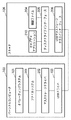
情報処理装置の一例であるコンピュータ100には、オペレーティングシステム101、ファイルシステム201、USBマスストレージドライバ202及びUSBインターフェースドライバ103がインストールされている。オペレーティングシステム101は、いわゆるOSのことであり、コンピュータ100の基本ソフトウエアである。ファイルシステム201は、ハードディスクドライブなどの記憶装置にファイルを格納するためのソフトウエアである。USBマスストレージドライバ202は、ハードディスクドライブ、CD−ROM、DVD−ROM、CD−R、DVD−R、USBメモリなどのマスストレージを制御するためのソフトウエアである。USBインターフェースドライバ103は、USBインターフェースに接続されたUSBデバイスを制御するためのソフトウエアである。なお、これらのソフトウエアはOSの一部であってもよい。
An
一方、周辺装置の一例であるスキャナ装置106には、コンピュータ100にスキャナ装置の制御を実行させるための制御プログラムを備えている。例えば、本実施形態では、キャプチャアプリケーション210、制御ファイル204、USBディスクドライブインターフェース205及びUSBマスストレージクラスインターフェース206が備えられている。本実施形態のキャプチャアプリケーション210は、ドライバプログラムを含み、コンピュータ100で実行されて画像を読み取るための制御を行うソフトウエアである。制御ファイル204は、キャプチャアプリケーション210を実行しているコンピュータ100からの制御コマンドなどが書き込まれるファイルである。USBディスクドライブインターフェース205は、スキャナ装置106に備えられているメモリ(RAM、フラッシュメモリ、EEPROMなど)をディスクドライブとして使用するためのソフトウエアである。USBマスストレージクラスインターフェース206は、USBディスクドライブインターフェース205を介してメモリをUSBマスストレージとして使用するためのソフトウエアである。
On the other hand, the
なお、市販のスキャナ装置は、これらのソフトウエアではなく、USBスキャナクラスインターフェースを備えている。そのため、パーソナルコンピュータは、キャプチャアプリケーションソフトウエアや専用のスキャナドライバを備える必要がある。本実施形態であれば、USBスキャナクラスインターフェースは必ずしも必要ではない。また、パーソナルコンピュータ側では、キャプチャアプリケーションソフトウエアや専用のスキャナドライバが必ずしも必要ではない。 Note that a commercially available scanner device has a USB scanner class interface instead of these software. Therefore, the personal computer needs to include capture application software and a dedicated scanner driver. In this embodiment, the USB scanner class interface is not always necessary. On the personal computer side, capture application software and a dedicated scanner driver are not necessarily required.
図2は、パーソナルコンピュータとして例示するコンピュータとスキャナのハードウエアブロック図である。図2において、コンピュータ100は、CPU121、ROM123、RAM124、ハードディスクドライブ122、USBインターフェース104を備えている。USBインターフェース104は、USBケーブル105を介してスキャナ装置106と接続される。また、CPU121は、キーボード/マウス125とディスプレイ126とが接続されている。
FIG. 2 is a hardware block diagram of a computer and a scanner exemplified as a personal computer. 2, the
コンピュータ100に電力が投入されると、CPU121は、ROM123からファームウエアを起動し、ハードディスクドライブ122からマイクロソフト(登録商標)ウインドウズ・オペレーティングシステム101を起動する。OSなどの必要なソフトウエアは、RAM124にロードされる。
When power is applied to the
一方、スキャナ装置106は、CPU110、ROM127、RAM203、画像読み取り部112、USBコントローラ128、USBインターフェース107を備えている。スキャナ装置106に電力が投入されると、CPU110は、ファームウエアをROM127から起動する。または不図示の不揮発性メモリから起動してもよい。
On the other hand, the
まず、コンピュータ100上のオペレーティングシステム101は、USBインターフェース104にUSBケーブル105を介して何らかの周辺デバイスが接続されると、周辺デバイスのインターフェースにアクセスし、周辺デバイスの種類を確定する。ここで、スキャナ装置106には、オペレーティングシステム101にマスストレージデバイスクラスとして認識される。マスストレージデバイスクラスデバイスを制御するためのUSBマスストレージドライバ202は、コンピュータに備えられており、新たにインストールする必要がないからである。それゆえ、本実施形態のスキャナ装置106は、USBマスストレージクラスインターフェース206を有している。
First, when a peripheral device is connected to the USB interface 104 via the
このように、マイクロソフト(登録商標)ウインドウズのオペレーティングシステム101は、標準で、マスストレージクラスのUSBデバイスをサポートしている。CPU121がマスストレージクラスのUSBデバイスにアクセスする際、オペレーティングシステム101がマスストレージクラスのUSBドライバ(USBマスストレージドライバ202)を含んでいるため、コンピュータ100への特別なデバイスドライバ等のインストールを必要としない。また、マスストレージクラスデバイスへの標準的なアクセスは、オペレーティングシステム101を使用して、管理者権限なしに実行されることが可能である。
As described above, the
よって、コンピュータ100にスキャナ装置106が接続されると、CPU121は、予めインストールされているUSBマスストレージドライバ202を起動する。また、スキャナ装置106が、USBマスストレージクラスインターフェース206を有しているため、コンピュータ100にスキャナ装置106を接続すると、CPU121及びオペレーティングシステム101は、スキャナ装置106をマスストレージデバイスとして認識する。さらに、CPU121及びオペレーティングシステム101は、スキャナ装置106のROM127やRAM203を外部記憶装置としてアクセスする。
Therefore, when the
この認識処理についてさらに詳細に説明する。コンピュータ100にスキャナ装置106が接続された場合、オペレーティングシステム101(CPU121)は、USBインターフェース104にて何らかの周辺デバイスの接続を検知し、USBケーブル105を介して、スキャナ装置106のUSBインターフェース107にアクセスする。スキャナ装置106のCPU110は、USBインターフェース107にコンピュータ100からアクセスがあると、USBマスストレージクラスインターフェース206にアクセスさせる。オペレーティングシステム101は、スキャナ装置106のUSBマスストレージクラスインターフェース206にアクセスすることで、予めオペレーティングシステム101に含まれているUSBマスストレージドライバ202を利用して、USBインターフェースドライバ103とUSBインターフェース104からUSBケーブル105を介してスキャナ装置106にアクセス可能になる。
This recognition process will be described in more detail. When the
また、スキャナ装置106は、オペレーティングシステム101に、マスストレージクラスデバイスとして認識されている。そのため、コンピュータ100は、スキャナ装置106のUSBインターフェース107、USBマスストレージクラスインターフェース206、USBディスクドライブインターフェース205を介して、管理者権限の有無に依存しないアクセス方法でスキャナ装置106にアクセスできる。ただし、コンピュータ100は直接的に画像読み取り部112を制御することはできず、あくまで記憶装置としてスキャナ装置106にアクセスできるにすぎない。
The
また、スキャナ装置106には、キャプチャアプリケーション210と、スキャナ装置106を制御するための制御ファイル204とを予めROM127またはRAM203に保存してある。ROM127またはRAM203は、フラッシュメモリ、EEPROM、DRAMなどの組み合わせによって実現可能である。キャプチャアプリケーション210は、コンピュータ100からの指令のもとにスキャナ装置106で画像読み取りを行うためのソフトウエアであり、オペレーティングシステム101上で動作する
さらに、コンピュータ100は、ファイルシステム201に関連付けたファイルフォルダ内に、スキャナ装置106内に保存してある制御ファイル204とキャプチャアプリケーション210に対応するテーブルを形成する。
In the
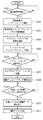
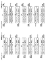
図3は、コンピュータ100からの指令のもとにキャプチャアプリケーション210を利用してスキャナ装置106で画像読み取りを行うフローのフローチャートである。
FIG. 3 is a flowchart of a flow in which the
コンピュータ100のCPU121は、スキャナ装置106が接続されたか否かを判断する(ステップS301)。CPU121は、周辺デバイス(スキャナ装置106)のインターフェースに接続する(ステップS302)。
The
CPU121は、周辺デバイスのインターフェースクラスの情報をスキャナ装置106から取得する(ステップS303)。この情報により接続された周辺装置の種類が認識できる。
The
上述したようにスキャナ装置106がUSBマスストレージインターフェースを有している。そのため、コンピュータ100にスキャナ装置106が接続されたとき、CPU121は、USBマスストレージデバイスが接続されたと認識する(ステップS304)。また、スキャナ装置106は、USBマスストレージクラスインターフェース206のサブクラスとして、USBディスクドライブインターフェース205を有している。そのため、CPU121は、接続されたスキャナ装置106をディスクドライブとして認識する。
As described above, the
オペレーティングシステム101は、スキャナ装置106内に保存してある制御ファイル204とキャプチャアプリケーション210に対応するテーブルを、ファイルシステム201に関連付けたファイルフォルダ内に形成する。このことによりCPU121は、スキャナ装置106内に格納してある制御ファイル204とキャプチャアプリケーション210を、ドライブレターを割り当てたディスクドライブ上のファイルとして扱うことができる(ステップS305)。これは、スキャナ装置106が、OSによってドライブレターを割り当てたディスクドライブとして認識されているからである。
The
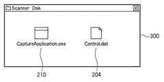
図4は、ドライブレターを割り当てられたディスクドライブ(スキャナ)をファイル管理ソフト(エクスプローラ)で開いた様子を示す図である。スキャナ装置106が内蔵するメモリは、フォルダ300に対応している。フォルダ300は、コンピュータ100に接続されたキーボード/マウス125を使用して開くことができる。フォルダ300には、キャプチャアプリケーション210(ファイル名:CaptureApplication.exe)と制御ファイル204(ファイル名:Control.dat)とが格納されている。
FIG. 4 is a diagram showing a state in which a disk drive (scanner) to which a drive letter is assigned is opened by file management software (Explorer). The memory built in the
CPU121は、フォルダ300内のキャプチャアプリケーション210を起動するための指示が入力されたか否かを判定する(ステップS306)。この指示は、キーボード/マウス125からユーザによって入力されてもよいし、フォルダ300に格納されている不図示のautorun.inf等の自動実行情報ファイルによって指示されてもよい。例えば、マイクロソフト(登録商標)ウインドウズオペレーティングシステムにおいては、CDドライブ内にCD−ROMが挿入されると、オペレーティングシステムは「autorun.inf」と呼ばれる、CD−ROM上の自動実行情報ファイルを検出し、「autorun.inf」内で自動実行することが指定された実行ファイルを実行する。また、マイクロソフト(登録商標)ウインドウズオペレーティングシステムのあるバージョンにおいては、USBディスクドライブ内に、「autorun.inf」、という名称のファイルが存在すると、その内部に記述されたコマンドを自動実行する。すなわち、「autorun.inf」内に自動実行させたい実行ファイル名を記述しておけば、利用者にキーボード/マウス125を操作させることなく自動的に起動させることも可能である。よって、実行ファイルとして上述のCaptureApplication.exeがautorun.inf内で記述されていることになる。キャプチャアプリケーション210を起動するための指示が入力されると、CPU121は、スキャナ装置106からキャプチャアプリケーションをメモリ(RAM124)にロードして起動する(ステップS307)。このようにスキャナ装置106のUSBインターフェースは、コンピュータ100からのソフトウエアのロード動作に応じて、ソフトウエアを送信する通信手段の一例である。
The
なお、autorun.inf等の自動実行情報ファイルにCaptureApplication.exeとは異なる、例えば異なる機能のautorun.exe等のソフトウエアの名称を記述しておいてもよい。コンピュータ100のメモリ(RAM124)にロードされて起動されたautorun.exeまたはCaptureApplication.exeによれば、USBディスクドライブインターフェース205を介して接続され、ディスクドライブとして認識されたスキャナ装置106を、スキャナドライバのインストールなしに制御することが出来る。すなわちCaptureApplication.exeやautorun.exe等の制御ソフトウエアは、USBメモリとして認識されるRAM上のファイルの受け渡しで画像読取及び画像形成の少なくとも一方に関するコマンドの送出と、画像データのスキャナからの移動を可能とするドライバ機能を有するものとする。またはドライバ機能を有するDLL(Dynamic Link Library)モジュール等の他のプログラムとリンクして、USBメモリとして認識されるRAM上のファイルの受け渡しを行うことによって、画像読取や画像形成に関するコマンドの送出と、画像データのスキャナからの移動やプリンタへの移動を可能とするようにしてもよい。
In addition, autorun. In the automatic execution information file such as inf, CaptureApplication. For example, autorun. The name of software such as exe may be described. Autorun.exe loaded into the memory (RAM 124) of the
なお、CaptureApplication.exeやautorun.exe等のソフトウエアが特定のDLLモジュール等にリンクする必要がある場合には、必要なDLLモジュール等をスキャナ装置106からコンピュータ100のメモリ(RAM124)にロードするようにしてもよい。
In addition, CaptureApplication. exe and autorun. When software such as exe needs to be linked to a specific DLL module or the like, the necessary DLL module or the like may be loaded from the
なお、自動実行情報ファイルはautorun.inf以外の名称であってもよい。また、マイクロソフト(登録商標)ウインドウズオペレーティングシステムにおいては、USBディスクドライブにおいても、電源投入時またはUSBコネクタが差し込まれたとき、CPU121は「autorun.inf」と呼ばれる、USBディスクドライブ上の自動実行情報ファイルを検出し、autorun.infの記述に従って、CaptureApplication.exe、autorun.exe等の起動を確認させるためのコンピュータ100のダイアログ画面を表示させて、ユーザの操作により起動可能な状態にすることができる。またオペレーティングシステム101の設定を変えれば、起動確認のダイアログ画面をコンピュータ100に表示させることなく、autorun.infの記述に従って、CaptureApplication.exe、autorun.exe等を起動させることもできる。
The automatic execution information file is autorun. A name other than inf may be used. Also, in the Microsoft (registered trademark) Windows operating system, even in a USB disk drive, when the power is turned on or the USB connector is inserted, the
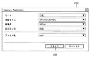
また、autorun.inf等の自動実行情報ファイルは、コンピュータウイルス等の悪意のプログラムや、悪意を持った人物による改ざんを防ぐために、周辺装置のメモリ領域のうち書き込み禁止にできる保護メモリ領域又は書き込み不可能なメモリ領域に記憶することが望ましい。ここで、本実施形態では、スキャナ装置106は、コンピュータ100の指示情報に基づいて制御される。詳細には、コンピュータ100からの指示情報は、コンピュータ100によるソフトウエアの実行により、スキャナ装置106の記憶手段に書き込まれる。そして、スキャナ装置106のCPU110は、記憶手段に書き込まれた指示情報に基づいてスキャナ装置106の動作を制御するようになっている。例えば、本実施形態では、コンピュータ100は、ディスプレイ126を接続しており、各種ユーザインターフェースをディスプレイ126に表示する。すなわち、コンピュータ100は、実際には、ソフトウエアの実行により、図5に示すようなユーザインターフェースを表示可能であり、ユーザは、このユーザインターフェースによりスキャナ装置106の制御条件を適宜指定できるようになっている。例えば、図5は、キャプチャアプリケーション210が起動したときに表示されるユーザインターフェースの一例を示した図である。図5に示すようなキャプチャアプリケーション210のインターフェースが表示されると、ユーザは、キーボード/マウス125を操作して、スキャン設定を実行する。例えば、読み取りモード(本実施形態では、白黒)、用紙サイズ(本実施形態では、A4)、解像度(本実施形態では、300dpi)、読み取り面(本実施形態では、両面)がキーボード/マウス125を使用して選択される。さらに、読み取った画像を保存するための画像ファイルのファイル名(本実施形態では、test1)もキーボード/マウス125を操作して入力される。最後に、スキャンボタン301がキーボード/マウス125を使用してクリックされる。
Also, autorun. An automatic execution information file such as inf is a protected memory area or a non-writable memory area in the memory area of the peripheral device in order to prevent malicious programs such as computer viruses and falsification by malicious persons. It is desirable to memorize. Here, in the present embodiment, the
スキャンボタン301がキーボード/マウス125によりクリックされると、キャプチャアプリケーション210(CPU121)は、スキャン設定を受け付け、スキャナ装置106内の制御ファイル204にスキャン設定(指示情報)を書き込む。さらに、CPU121は、スキャン開始コマンドデータ(指示情報)も制御ファイル204に書き込む(ステップS308)。
When the
スキャナ装置106のCPU110は、制御ファイル204を監視している。そうして、CPU110は、スキャン設定およびスキャン開始コマンドデータが制御ファイル204に書かれたことを検出すると、制御ファイル204を読み込んで、そこに書かれているスキャン設定にしたがって画像読み取り部112を制御し、スキャンを開始する。以上のように、情報処理装置が接続されて所定の処理が実行される本スキャナ装置は、スキャナ装置を利用可能とするプログラムを格納すると共にスキャナ装置を制御するための指示情報が書き込み可能なメモリと、情報処理装置に対してメモリからプログラムを送信する通信手段と、情報処理装置の前記プログラムの実行によりメモリに書き込まれた前記指示情報に基づいてスキャナ装置を制御する制御手段とを備えていることを特徴としている。
The
スキャナ装置106はスキャンを開始すると、画像読み取り部112で読み取った画像データをCPU110は制御ファイルに書き込む。この制御ファイルは、スキャン設定を可能としている制御ファイルと同一であってもよいし、異なってもよい。
When the
コンピュータ100のCPU121は、画像データが制御ファイル204に書き込まれたか否かを監視する(ステップS309)。画像データが制御ファイル204に書き込まれたことを検出すると、制御ファイル204から画像データを読み出す(ステップS310)。CPU121は、指定された画像ファイル(本実施形態では、ファイル名「test1」)を作成し、ハードディスクドライブ122に記憶する(ステップ311)。本実施形態の周辺装置はプリンタや複合機等の画像形成機能を有する装置でもよい。CaptureApplication.exeやautorun.exe等の制御ソフトウエアは、USBメモリとして認識されるRAM上のファイルの受け渡しで画像読取及び画像形成の少なくとも一方に関するコマンドの送出と、画像データのスキャナからの移動やプリンタ等への移動を可能とするドライバ機能を有するものであってもよい。またはドライバ機能を有するDLL(Dynamic Link Library)モジュール等の他のプログラムとリンクして、USBメモリとして認識されるRAM上のファイルの受け渡しを行うことによって、画像読取や画像形成に関するコマンドの送出と、画像データのスキャナからの移動やプリンタ 等への移動を可能とするようにしてもよい。
The
以上説明したように、本実施形態によれば、コンピュータ100にデバイスドライバやアプリケーションなどのソフトウエアをインストールすることなく、スキャナ装置106で画像読み取りを行うことができるようになる。例えば、管理者権限がなくオペレーティングシステム101においてインストーラにログインできないユーザや、外出先のパーソナルコンピュータを使用するユーザであっても、容易に、画像読み取りを行うことができる
本実施形態ではUSBマスストレージクラスインターフェース206のUSBディスクドライブインターフェース205を介して読出し可能なRAM203等にCaptureApplication.exe210やautorun.infやautorun.exe等の制御用のソフトウエアが常時記憶されているようになっている。しかし、電源投入時や初期化時や所定のコマンドを受けたとき等に不図示のROM等に記憶されたファームウエア等の制御により、ROMや不揮発性メモリ等に記憶された情報に基づいてRAM203等に、USBマスストレージクラスインターフェースを介して読み出し可能なように、その都度autorun.infやCaptureApplication.exeやautorun.exe等を格納するようにしてもよい。もちろんROMや不揮発性メモリ等にautorun.infやCaptureApplication.exeやautorun.exe等がそのまま記憶されている場合は、RAM203等に複製するようにしてもよい。このようにROMや不揮発性メモリ等に記憶された情報に基づいてRAM203等に格納又は複製された制御用のソフトウエアは、コンピュータ100のメモリ(RAM124)にロードされ起動される。起動された制御用のソフトウエアは、制御ファイル204へのコマンド等の書き込みの制御や、画像データを制御ファイル204から読み出したり制御ファイル204へ書き込んだりする制御を実行する。
As described above, according to the present embodiment, the
これらの制御用のソフトウエア(CaptureApplication.exe210等)はRAM203等から消去することも可能であり、USBマスストレージクラスインターフェースを介して読み書き可能なRAM203等の記憶容量を、他の目的に有効に活用することができる。また、万一コンピュータウイルス等の感染がこれらの制御用のソフトウエアに認められた場合は、これらの制御用のソフトウエアを消去することによって、感染の拡大を防ぐことができる。 These control software (CaptureApplication.exe210, etc.) can be deleted from the RAM203, etc., and the storage capacity of the RAM203, etc., which can be read and written via the USB mass storage class interface, is effectively utilized for other purposes. can do. In addition, if an infection such as a computer virus is recognized in these control software, the spread of the infection can be prevented by erasing these control software.
なお、CaptureApplication.exeやautorun.exe等の制御用のソフトウエアは、コンピュータ100のメモリ(RAM124)にロードして起動することで使用可能となるものであり、インストールする必要がないソフトウエアであることが特徴である。また、本実施形態ではコンピュータ100によってスキャナ装置106のRAM203が1つのディスクドライブとしてドライブレターを割り当てられて認識される。不図示のROMや不揮発性メモリ等はコンピュータ100からは認識されないことが望ましい。このようにするとスキャナ装置106に対してドライブレターは1つだけ割り当てられるので、他の機器のために必要とされるドライブレターを浪費することがない。以上説明したように、本発明の第1の実施形態では、コンピュータ100にデバイスドライバやアプリケーションなどのソフトウエアをインストールすることなく、スキャナ装置106で画像読み取りを行うことができるようになる。例えば、管理者権限がなくオペレーティングシステム101においてインストーラにログインできないユーザや、外出先のパーソナルコンピュータを使用するユーザであっても、容易に、画像読み取りを行うことができる。
In addition, CaptureApplication. Control software such as exe and autorun.exe can be used by loading it into the memory (RAM 124) of the
<第2の実施形態>
図6は、本発明の第2の実施形態に係る、コンピュータと画像読み取り装置としてのスキャナのソフトウエアブロック図である。すでに説明した箇所に同一の参照符号を付与することで説明を簡潔にする。
<Second Embodiment>
FIG. 6 is a software block diagram of a computer and a scanner as an image reading apparatus according to the second embodiment of the present invention. The description will be simplified by giving the same reference numerals to the parts already described.
第1の実施形態で説明したUSBマスストレージクラスインターフェース206は、複数のUSBマスストレージサブクラスを有することが可能である。そこで、第2の実施形態では、USBディスクドライブインターフェース205とUSB CDドライブインターフェース208といった2つのサブクラスがスキャナ装置106に備えられている。コンピュータ100上のオペレーティングシステム101は、それぞれを論理的に別個のデバイスとしてアクセス可能である。すなわち、コンピュータ100のCPU121は、スキャナ装置106を2つの論理的に異なるディスクドライブとして認識し、ドライブレターをそれぞれに割り当てる。
The USB mass
より詳細に説明する。コンピュータ100にスキャナ装置106が接続されると、オペレーティングシステム101(CPU121)は、USBインターフェース104にて何らかの周辺デバイスの接続を検知する。そして、CPU121は、USBケーブル105を介して、スキャナ装置106のUSBインターフェース107にアクセスする。
This will be described in more detail. When the
スキャナ装置106のCPU110は、USBインターフェース107にコンピュータ100からアクセスがあると、USBマスストレージクラスインターフェース206にアクセスさせる。このように、オペレーティングシステム101は、スキャナ装置106のUSBマスストレージクラスインターフェース206へアクセスする。これにより、CPU121は、予めオペレーティングシステム101に含まれているUSBマスストレージドライバ202を利用して、USBインターフェースドライバ103とUSBインターフェース104からUSBケーブル105を介してスキャナ装置106にアクセス可能になる。
The
また、スキャナ装置106は2つのUSBマスストレージサブクラスを有していることから、オペレーティングシステム101は2つのマスストレージクラスデバイスとしてスキャナ装置106を認識する。よって、コンピュータ100のCPU121は、スキャナ装置106のUSBインターフェース107、USBマスストレージクラスインターフェース206、USB CDドライブインターフェース208あるいはUSBディスクドライブインターフェース205を介して、管理者権限を持たないユーザが利用可能なアクセス方法によってスキャナ装置106にアクセスできる。
Since the
また、スキャナ装置106には、オートランファイル207と、キャプチャアプリケーション210と、制御ファイル204とが予め保存されている。オートランファイル207は、上述したautorun.infなどである。
In the
なお、コンピュータ100のCPU121は、USB CDドライブインターフェース208を介して、制御ファイル204は、USBディスクドライブインターフェース205を介して、キャプチャアプリケーション210とオートランファイル207とにアクセスする。
The
上述したように、オペレーティングシステム101がマイクロソフト(登録商標)ウインドウズであれば、CDドライブ内にデータCDが挿入されると「autorun.inf」(オートランファイル207)の読出しを実行する。オートランファイル207は、USB CDドライブインターフェース208を介してアクセスされるため、自動的に読み出されて処理されることになる。
As described above, if the
スキャナ装置106のCPU110は、コンピュータ100に接続した時点で、CDドライブ内にデータCDが挿入されていない状態であるとオペレーティングシステム101に仮想的に認識させる。次に、CPU110は、CDが挿入されたことをオペレーティングシステム101に仮想的に認識させることで、オートランファイル207が自動実行されるように制御する。
When connected to the
さらに、コンピュータ100は、スキャナ装置106に保存してある制御ファイル204とキャプチャアプリケーション210とオートランファイル207に対応するテーブルを、ファイルシステム201に関連付けられたフォルダ内に形成する。
Furthermore, the
図7は、コンピュータ100からキャプチャアプリケーション210を利用してスキャナ装置106で画像読み取りを行うフローを示したフローチャートである。既に説明した箇所には同一の参照符号を付与することで、説明を簡潔にする。
FIG. 7 is a flowchart showing a flow of reading an image with the
ステップS301ないしステップS304が実行されると、コンピュータ100のCPU121は、マスストレージデバイスが接続された認識する。スキャナ装置106は、USBマスストレージクラスインターフェース206のサブクラスとして、USB CDドライブインターフェース208とUSBディスクドライブインターフェース205を有している。そのため、コンピュータ100のCPU121は、接続されたスキャナ装置106をそれぞれ、CDドライブとディスクドライブとして認識する(ステップS705)。
When steps S301 to S304 are executed, the
上述のように、オペレーティングシステム101(CPU121)は、ファイルシステム201に関連付けられたファイルフォルダ内に、スキャナ装置106内に保存してある制御ファイル204とキャプチャアプリケーション210とオートランファイル207に対応するテーブルを形成する。そのため、CPU121は、スキャナ装置106内に保存してある制御ファイル204をディスクドライブ上のファイルとして認識する。また、CPU121は、キャプチャアプリケーション210とオートランファイル207をCDドライブ上のファイルとして認識する。
As described above, the operating system 101 (CPU 121) stores tables corresponding to the
図8は、CDドライブとして認識されているメモリ領域に対応したフォルダの一例を示した図である。すなわち、スキャナ装置106のROMやRAMのうち、CDドライブとして認識されているメモリ領域がフォルダ302としてコンピュータ100には認識される。よって、フォルダ302に、キャプチャアプリケーション210とオートランファイル207が格納されているように見える。
FIG. 8 is a diagram showing an example of a folder corresponding to a memory area recognized as a CD drive. That is, the memory area recognized as the CD drive in the ROM and RAM of the
図9は、ディスクドライブとして認識されているメモリ領域に対応したフォルダの一例を示した図である。スキャナ装置106のROMやRAMのうち、ディスクドライブとして認識されているメモリ領域がフォルダ303としてコンピュータ100には認識される。よって、フォルダ303に、制御ファイル204が格納されているように見える。
FIG. 9 is a diagram showing an example of a folder corresponding to a memory area recognized as a disk drive. Of the ROM and RAM of the
ユーザは、図8に示すようなフォルダ302と図9に示すようなフォルダ303をコンピュータ100に接続されたキーボード/マウス125を使用して開くことができる。
The user can open the
オペレーティングシステム101(CPU121)は、CDドライブ内にデータCDが挿入されたと判断すると、オートランファイル207を実行する(ステップS706)。オートランファイル207は、予め、キャプチャアプリケーション210を起動するように記述されている。そのため、CPU121は、オートランファイル207の記述を解釈して、キャプチャアプリケーション210を起動する(ステップS707)。ユーザの操作は不要であるため、ユーザには、キャプチャアプリケーション210が自動的に起動されたように見える。
If the operating system 101 (CPU 121) determines that the data CD has been inserted into the CD drive, it executes the autorun file 207 (step S706). The auto-
なお、図8のようなCDドライブとして認識される領域を設けず、RAM124が図9のようなUSBディスクドライブとしてだけ認識されるようにしてもよい。その場合autorun.infとCaptureApplication.exe、autorun.exe等をUSBディスクドライブとして認識されているRAM124のメモリ領域に格納すればよい。必要があればそこにDLLモジュールも格納する。電源投入時またはUSBコネクタが差し込まれたとき、autorun.infの記述に従って、CaptureApplication.exe、autorun.exe等の起動を確認させるためのダイアログ画面をコンピュータ100に表示させて、ユーザの操作により起動可能な状態にすることができる。またオペレーティングシステム101の設定を変えれば、起動確認のダイアログ画面をコンピュータ100に表示させることなく、autorun.infの記述に従って、CaptureApplication.exe、autorun.exe等を起動させることもできる。
Note that the
また、図8でCDドライブとして認識されると示した領域の代わりに、読取のみ可能なUSBディスクドライブとして認識される領域を設け、RAM124が複数個のUSBディスクドライブとしてコンピュータ100に認識されるようにしてもよい。その場合、autorun.infとCaptureApprlication.exe、autorun.exe等を、読取のみ可能なUSBディスクドライブとして認識されているRAM124のメモリ領域に格納することで、これらのファイルが悪意を持った人物に改ざんされることを防ぐこともできる。
Further, instead of the area shown as being recognized as a CD drive in FIG. 8, an area recognized as a readable USB disk drive is provided, so that the
その後、上述したステップS308ないしS311が実行される。 Thereafter, the above-described steps S308 to S311 are executed.
以上、2つの実施形態で説明したように、本実施形態では、コンピュータ100にデバイスドライバやアプリケーションなどのソフトウエアをインストールすることなく、スキャナ装置106で画像読み取りを行うことができるようになる。例えば、管理者権限がなくオペレーティングシステム101においてインストーラにログインできないユーザや、外出先のパーソナルコンピュータを使用するユーザであっても、容易に、画像読み取りを行うことができる。
As described above in the two embodiments, in this embodiment, the
なお、上記の第1及び第2の各実施形態においては、キャプチャアプリケーション210からスキャンを開始する例を説明した。しかし、スキャナ装置106上にスタートボタン等を配置し、スタートボタンを押下されたことをCPU110が検知すると、スキャンを開始してもよい。その際、キャプチャアプリケーション210(CPU121)は、スキャナ装置106のスタートボタンを、制御ファイル204を介して監視してもよい。この場合は、CPU110がスタートボタンを押下されたことを示す情報を制御ファイル204に書き込むことになる。
In each of the first and second embodiments, the example in which scanning is started from the
キャプチャアプリケーション210は、スキャナ装置106に制御ファイル204を介してスキャン開始を指示してもよいし、キャプチャアプリケーション210が、制御ファイル204に画像データが生成されたことを検知して、スキャンが開始されたと判断し、画像データを読み出して画像ファイルをハードディスクドライブに保存しても良い。
The
また、上記第1及び第2の実施形態においては、キャプチャアプリケーション210を起動し、ユーザインターフェースを表示しているが、スキャナ装置106を最初に接続した後は、マイクロソフト(登録商標)ウインドウズ等のオペレーティングシステム101に常駐してもよい。
In the first and second embodiments, the
また、上記第1及び第2の実施形態においては、キャプチャアプリケーション210には画像表示機能が無いが、キャプチャアプリケーション210が読み取られた画像の表示機能を備えていても良い。
In the first and second embodiments, the
また、上記第1及び第2の実施形態においては、RAM203の制御ファイル204にスキャン設定を書き込んでいるため、スキャン設定がスキャナ装置106に保存されない。しかし、スキャナ装置106内で、設定されたスキャン設定を不図示の不揮発メモリ等に記憶しておいても良い。また、オペレーティングシステム101のユーザ毎に、別々のスキャン設定を記憶しておいても良い。
In the first and second embodiments, since the scan setting is written in the
また、上記第1及び第2の実施形態においては、マイクロソフト(登録商標)ウインドウズオペレーティングシステム上での動作を例にとって説明した。しかしこれは一例にすぎない。本発明は、アップル社のオペレーティングシステムやリナックスオペレーティングシステム等、その他のオペレーティングシステムにも適用できる技術思想だからである。 In the first and second embodiments, the operation on the Microsoft (registered trademark) Windows operating system has been described as an example. But this is only an example. This is because the present invention is a technical idea that can be applied to other operating systems such as Apple's operating system and Linux operating system.
また、上記第1及び第2の実施形態においては、画像読み取り装置を例にとって説明したが、プリンタでもよく、画像読み取り機能と画像形成機能を併せ持つ複合機等でもよい。
なお、本発明の周辺装置が画像形成機能を有する場合は画像形成に関するコマンドの送出の機能と、画像形成に用いる画像データの送出の機能とを、autorun.exe等のソフトウエアは備えることになる。
In the first and second embodiments, the image reading apparatus has been described as an example. However, a printer or a multifunction machine having both an image reading function and an image forming function may be used.
When the peripheral device of the present invention has an image forming function, a function for sending a command related to image formation and a function for sending image data used for image formation are described in autorun. Software such as exe will be provided.
<第3の実施形態>
第1の実施形態や第2の実施形態では、デバイスドライバのインストールが不要となる反面、常に、専用のキャプチャアプリケーションを使用する必要がある。一方で、デバイスドライバのインストールが許可されているコンピュータでは、普及した汎用のキャプチャアプリケーションを使用したいという要望も予想される。
<Third Embodiment>
In the first and second embodiments, installation of a device driver is not necessary, but a dedicated capture application must always be used. On the other hand, it is expected that a computer that is permitted to install a device driver will want to use a general-purpose capture application.
そこで、本実施形態では、専用のデバイスドライバのインストールを必要とする制御モードと、上述した第1の実施形態又は第2の実施形態のように、専用のデバイスドライバ等のソフトウエアのインストールを必要としない制御モードとを備え、両者を切り替えることができる周辺装置について提案する。なお、後者のモード、すなわち、ソフトウエアのインストールを必要としない制御モードについては、上述した第1の実施形態又は第2の実施形態と同様である。以下、専用のデバイスドライバ等のソフトウエアのインストールを必要とする制御モードについて詳細に説明する。 Therefore, in this embodiment, a control mode that requires the installation of a dedicated device driver and the installation of software such as a dedicated device driver as in the first or second embodiment described above are required. Proposed is a peripheral device that has a control mode that can not be switched and can be switched between. Note that the latter mode, that is, the control mode that does not require software installation, is the same as in the first embodiment or the second embodiment described above. Hereinafter, a control mode that requires installation of software such as a dedicated device driver will be described in detail.
図10は、第3の実施形態に係るソフトウエアブロック図である。既に説明した箇所には同一の参照符号が付与されている。図1と比較すると、汎用のキャプチャアプリケーション222と、USBスキャナドライバ102と、スイッチ220がコンピュータ100に追加されている。一方、スキャナ装置106には、USBスキャナクラスインターフェース108とスイッチ221とが追加されている。
FIG. 10 is a software block diagram according to the third embodiment. The parts already described are given the same reference numerals. Compared to FIG. 1, a general-
コンピュータ100上のオペレーティングシステム101は、USBインターフェース104にUSBケーブル105を介して何らかの周辺デバイスが接続された場合、周辺デバイスのインターフェースにアクセスし、周辺デバイスの種類を確定する。ここで、スキャナ装置106には、オペレーティングシステム101にマスストレージデバイスクラスとして認識してもらうためのUSBマスストレージクラスインターフェース206と、スキャナデバイスクラスとして認識してもらうためにUSBスキャナクラスインターフェース108とを有している。
When any peripheral device is connected to the USB interface 104 via the
これらの2つの異なるクラスのインターフェースは、スイッチ221によって択一的に切り替えられる。なお、スイッチ221は、第3の制御モードとして、2つのクラスのインターフェースを同時に有効にするように切り替えてもよい。スイッチ221は、ソフトウエアで実現されてもよいし、電気的に切り替え可能な電子スイッチを用いてハードウエアによって実現されてよい。また、ソフトウエア及びハードウエアの両方も用いてスイッチ221が実現されてもよい。
These two different classes of interfaces are alternatively switched by a
具体的には、上記のハードウエアにより実現されるスイッチ221としては、例えば、ユーザが手で切り替え可能なスイッチ等が挙げられる。またはスイッチ221の切り替えのための電気信号を生成する他の手動スイッチを別途設けてもよい。これらの場合後述するような制御が可能なスイッチと異なり、CPU110の制御によるスイッチ221の切り替えができない。このようなとき表示LED等を設けCPU110からLED等の点灯を制御することによりユーザに手でスイッチ221等を切り替えさせるようにしてもよい。
Specifically, as the
なお、このような手で切り替え可能なスイッチ221又は他の手動スイッチを設けた場合は、スイッチの切り替え状態に応じてスキャナ装置106の不図示の操作ボタンを押した場合の動作を異ならせることができる。例えば、スイッチ221又は他の手動スイッチをUSBマスストレージクラスインターフェース206を認識可能とする側に切り替えておき、不図示のスキャン開始ボタンを押すと、USBの接続が遮断された状態への遷移と、その後再びUSBの接続が行なわれた状態への遷移とを擬似的に起こすこともできる。これらの遷移により、USBのコネクタに触れることなく、USBの抜き差しを行った場合に実行されるオートランプログラムの起動やオートランの確認ダイアログの表示を可能とし、画像読取を少ない操作で行うことができる。
When such a
また、このような手で切り替え可能なスイッチ221又は上述した他の手動スイッチをUSBスキャナクラスインターフェース108を認識させる側に切り替えておき、不図示のスキャン開始ボタンを押すと、所定のJOBをコンピュータ100上で動作させるための情報をコンピュータ100に送信したり、あるいは制御ファイルにJOBを起動させるための情報を書き込んだりするようにすることもできる。
Further, when such a
一方、コンピュータ100上で動作するオペレーティングシステム101は、マスストレージクラスのUSBデバイスをサポートしている。オペレーティングシステム101がマスストレージクラスデバイスのデバイスドライバであるUSBマスストレージドライバ202を含んでいる。そのため、ユーザは、コンピュータ100への特別なデバイスドライバをインストールすることを要求されることはない。また、マスストレージクラスデバイスへの標準的なアクセスは、オペレーティングシステム101を通じて、管理者権限なしに、実行可能である。
On the other hand, the
よって、コンピュータ100にスキャナ装置106を接続したとき、予めインストールされているUSBマスストレージドライバ202が使用される。また、スキャナ装置106は、USBマスストレージクラスインターフェース206を有している。そのため、コンピュータ100にスキャナ装置106を接続すると、スキャナ装置106がマスストレージデバイスとしてオペレーティングシステム101に認識され、アクセスが可能となる。
Therefore, when the
なお、コンピュータ100内のスイッチ220を切り替えることで、USBマスストレージドライバ202以外のドライバへ接続を切り替えることができるものとする。スイッチ220は、ソフトウエアで実現されてもよいし、電気的に切り替え可能な電子スイッチを用いてハードウエアによって実現されてよい。また、ソフトウエア及びハードウエアの両方も用いてスイッチ220が実現されてもよい。
It is assumed that the connection can be switched to a driver other than the USB
また、USBマスストレージクラスインターフェース206は、複数のUSBマスストレージサブクラスを有することが可能である。図6に示したように、2つのサブクラスを有するようにスキャナ装置106が変更されてもよい。
The USB mass
コンピュータ100に予めインストールされているキャプチャアプリケーション222は、スキャナ装置106で画像読み取りを行うためのソフトウエアである。USBスキャナドライバ102は、スキャナ装置106を、USBインターフェースを介して接続するためのデバイスドライバである。これは、標準でOSには用意されていない専用のデバイスドライバである。よって、USBスキャナクラスインターフェース108が有効に設定されているときは、USBスキャナドライバ102を通じて画像の読取が実行される。
A
本実施形態においては、管理者権限を有するユーザが、予めキャプチャアプリケーション222とUSBスキャナドライバ102をコンピュータ100へインストールしているものとする。USBマスストレージドライバ202とUSBスキャナドライバ102は、スイッチ220によって切り替えられる。もちろん、双方が同時に有効にされてもよい。
In this embodiment, it is assumed that a user having administrator authority has installed the
コンピュータ100にスキャナ装置106が接続された場合、オペレーティングシステム101は、USBインターフェース104にて何らかの周辺デバイスの接続を検知し、USBケーブル105を介して、スキャナ装置106のUSBインターフェース107にアクセスする。スキャナ装置106のCPU110は、USBインターフェース107にコンピュータ100からアクセスがあると、切り替えスイッチ221をUSBマスストレージクラスインターフェース206に切り替え、USBマスストレージクラスインターフェース206にアクセスさせる。オペレーティングシステム101は、スキャナ装置106のUSBマスストレージクラスインターフェース206にアクセスすることで、切り替えスイッチ220を切り替えてUSBマスストレージドライバ202を有効にし、USBインターフェース104からUSBケーブル105を介してスキャナ装置106にアクセスする。
When the
スキャナ装置106は、オペレーティングシステム101に、マスストレージクラスデバイスとして認識されている。そのため、コンピュータ100は、スキャナ装置106のUSBインターフェース107、USBマスストレージクラスインターフェース206、USBディスクドライブインターフェース205を介して、オペレーティングシステム101の管理者権限なしに実行できるアクセス方法でスキャナ装置106にアクセスができる。
The
スキャナ装置106には、コンピュータ100からスキャナ装置106で画像読み取りを行うためのオペレーティングシステム101上で動作するキャプチャアプリケーション210と、スキャナ装置106を制御するための制御ファイル204とを予め保存してある。
In the
さらに、コンピュータ100は、スキャナ装置106内に保存してある制御ファイル204とキャプチャアプリケーション210に対応するテーブルを、ファイルシステム201に関連付けたファイルフォルダ内に形成する。これらのテーブルを形成することでスキャナ装置106内の制御ファイル204とキャプチャアプリケーション210は、例えばコンピュータ100の画面に表示されるようになる。本実施形態の説明では、スキャナ装置106内のキャプチャアプリケーション210を使用する動作モードの説明は省略する。
Further, the
図11は、ユーザが、コンピュータ100にインストールしてあるキャプチャアプリケーション222を起動して、スキャナ装置106で画像読み取りを行うフローを示したフローチャートである。
FIG. 11 is a flowchart showing a flow in which the user activates the
コンピュータ100はスキャナ装置106が接続されたか否かを監視する(ステップS1101)。コンピュータ100はUSBマスストレージクラスインターフェースを有する装置としてスキャナ装置106を接続する(ステップS1102)。コンピュータ100は周辺デバイスのインターフェースクラス等の情報をスキャナ装置106から取得する(ステップS1103)。コンピュータ100は、取得した情報により、接続された周辺デバイスの種類を認識できる。
The
ところで、スキャナ装置106の切り替えスイッチ221は、通常、USBマスストレージインターフェースに切り替えられている。そのため、コンピュータ100はスキャナ装置106をUSBマスストレージデバイスと認識する(ステップS1104)。コンピュータ100は、切り替えスイッチ220をUSBマスストレージドライバ202に切り替え、接続されたスキャナ装置106をディスクドライブとしてファイルシステムに追加する(ステップS1105)。
Incidentally, the
このようにして、コンピュータ100は、マスストレージとしてスキャナ装置106を認識する。コンピュータ100は、キャプチャアプリケーション222の起動が指示されたか否かを判定する。(ステップS1106)。キャプチャアプリケーション222の起動が指示されると、コンピュータ100は、キャプチャアプリケーション222を起動する(S1107)。
In this way, the
コンピュータ100はスキャナ装置106がマスストレージデバイスとして認識されていることをファイルシステム201から検知する。そこで、コンピュータ100は、ファイルシステム201を経由してスキャナ装置106に対して、USBスキャナクラスインターフェース108で接続しなおすように指示を出す(ステップS1108)。スキャナ装置106は、USBスキャナクラスクラスへのインターフェースの切り替えの指示を受信した場合、一度、コンピュータ100への接続状態から切断状態に移行した後、再度、接続状態に移行する。
The
このとき、オペレーティングシステム101は、USBインターフェース104にて何らかの周辺デバイスの接続を検知する(ステップS1109)。スキャナ装置106のCPU110は、USBインターフェース107にコンピュータ100からのアクセスがあると、切り替えスイッチ221をUSBスキャナクラスインターフェース108が有効となるように切り替え、コンピュータ100にUSBスキャナクラスインターフェース108へアクセスさせる(S1110)。これによりコンピュータ100は、装置のインターフェースクラスの情報等を取得する(ステップS1111)。取得した情報は、コンピュータ100がUSBスキャナクラスインターフェース108に接続したことを示している。よって、コンピュータ100は、接続された周辺デバイスがスキャナデバイスであると認識する(ステップS1112)。
At this time, the
次に、ユーザは、キャプチャアプリケーション222が起動されているため、ディスプレイ126にはユーザインターフェース画面が表示されている(図5)。本実施形態でのキャプチャアプリケーション222はキャプチャアプリケーション210と同一のユーザインターフェースを使用しているが、両者は異なってもよい。ユーザは、キャプチャアプリケーション222で、読み取りモード(本実施形態では、白黒)、用紙サイズ(本実施形態では、A4)、解像度(本実施形態では、300dpi)、読み取り面(本実施形態では、両面)を設定する。この設定には、キーボード/マウス125が使用される。また、画像ファイルのファイル名(本実施形態では、test1)もキーボード/マウス125を使用して入力される。最後に、スキャンボタン301がキーボード/マウス125によりクリックされる。
Next, since the user has activated the
スキャンボタン301がクリックされると、キャプチャアプリケーション222(CPU121)は、USBスキャナドライバ102、USBインターフェースドライバ103及びUSBインターフェース104を介して、スキャナ装置106に、スキャン設定を送信するとともに、スキャン開始コマンドを送信する(ステップS1113)。(以下はスキャナクラスのため:受信receive)
スキャナ装置106は、USBインターフェース107からUSBスキャナクラスインターフェースを介して、スキャン設定およびスキャン開始コマンドデータを受信したことを検出する。スキャナ装置106は、受信したスキャン設定にしたがってスキャンを開始する。
When the
The
コンピュータ100は、スキャナ装置106の画像読み取り部112が読み取った画像データを、USBスキャナクラスインターフェース108及びUSBインターフェース107を介して受信する(ステップS1114、S1115)。キャプチャアプリケーション222は、受信した画像データを結合し、指定されたファイル名(本実施形態では、test1)の画像ファイルとしてハードディスクドライブに保存する(ステップS1116)。
The
なお、コンピュータ100にUSBスキャナドライバ102をインストールできないときの動作は、第1及び第2の実施形態と変わらないため、説明を省略する。
Note that the operation when the
<第4の実施形態>
図12は、第4の実施形態に係るソフトウエアブロック図である。図12と図10とを比較するとわかるように、スキャナ装置106のソフトウエア構成が第2の実施形態と第3の実施形態とを組み合わせたものとなっている。すなわち、インストールに関して制限のあるコンピュータにスキャナ装置106が接続されたときは、第2の実施形態で説明したようにコンピュータ及びスキャナ装置106が動作する。一方で、既にUSBスキャナドライバ102やキャプチャアプリケーション222がすでにインストールされているコンピュータでは、第3の実施形態で説明したようにコンピュータ及びスキャナ装置106が動作する。
<Fourth Embodiment>
FIG. 12 is a software block diagram according to the fourth embodiment. As can be seen by comparing FIG. 12 and FIG. 10, the software configuration of the
[画像転送処理]
図13は、上記第2、第4実施形態での画像転送処理の一例を示したフローチャートである。スキャナ装置106のCPU110は、制御ファイル204にスキャン開始コマンドが書き込まれたか否かを確認する(ステップS1301)。スキャン開始コマンドが書き込まれたことを検知すると、CPU110は、画像読み取り部112を制御してスキャンを開始し、読み取った画像の画像データをCPU110が制御ファイル204に書き込む(ステップS1302)。CPU110は、1ページ分の画像データについて制御ファイル204への書き込みが終了したか否かを判定する(ステップS1303)。これが終了すると、CPU110は、コンピュータ100にリムーバブルメディアが交換された旨を、USBケーブル105を通じて通知する(S1304)。
[Image transfer processing]
FIG. 13 is a flowchart showing an example of image transfer processing in the second and fourth embodiments. The
オペレーティングシステム101は、リムーバブルメディアが交換された旨の通知を受信すると、リムーバブルメディアが交換されたと判断し、スキャナ装置106に記憶されている制御ファイル204に対応したファイルシステム201の管理テーブルを更新する。CPU121は、更新された管理テーブルを読み、制御ファイル204に画像データが書き込まれたことを認識する。
When the
CPU121が実行しているキャプチャアプリケーション210は、書き込まれた画像データを制御ファイル204から抽出し、抽出した画像データを結合して1つの画像ファイルを生成し、指定されたファイル名(上記実施形態では、test1)を付与してハードディスクドライブに保存する。上述したようにリムーバブルメディアが交換されたと判断される状態にする方法の他に、画像データの格納の完了等をコンピュータに通知する方法は、下記のような例示する方法が可能である。
The
[画像転送処理の他の例]
図14は、上記第4実施形態でのコンピュータ側の画像転送処理の一例を示したフローチャートである。図15は、上記第4実施形態でのスキャナ装置側の画像転送処理の一例を示したフローチャートである。
[Other examples of image transfer processing]
FIG. 14 is a flowchart showing an example of image transfer processing on the computer side in the fourth embodiment. FIG. 15 is a flowchart showing an example of image transfer processing on the scanner device side in the fourth embodiment.
上記実施形態のマスストレージクラスデバイスは、SCSIコマンド体系での送受信をサポートしている。つまり、コンピュータ100は、マスストレージデバイスに対して、SCSIコマンド体系で、コマンドを発行する。また、コンピュータ100のマイクロソフトウインドウズ(登録商標)オペレーティングシステム101は、マスストレージデバイスの接続があると、定期的に、Test Unit Readyコマンドを発行する。
The mass storage class device of the above embodiment supports transmission / reception using the SCSI command system. That is, the
コンピュータ100から、スキャナ装置106にスキャン開始指示を行うとき、まず、キャプチャアプリケーション210は、制御ファイル204にスキャン開始命令を書き込む。具体的には、マイクロソフトウインドウズ(登録商標)オペレーティングシステム101は、Writeコマンドを発行し、パラメータデータでスキャン開始命令を送信する(S1401、S1402、S1403)。
When the
スキャナ装置106は、Writeコマンドのパラメータデータでスキャン開始命令を受信し、スキャンパラメータを制御ファイル204から読み出して受け付けると(S1501,S1502)、スキャンを開始し、画像読み取り部112で読み取った画像データを制御ファイル204に書き込む(S1503)。
When the
このとき、スキャナ装置106は、画像読み取り中の画像データが制御ファイル204に書き込み中である場合、Test Unit Readyコマンドに対して、正常状態を示すGOODステータスを返す(S1504,S1505)。コンピュータ100は、定期的にTest Unit Readyコマンドを送信する(S1404)。
At this time, if the image data being read is being written to the
その後、スキャナは、画像データの制御ファイル204への書き込みが終了した場合(S1506)、Test Unit Readyコマンドに対して(S1507)、書き込み終了を通知するためにCHECK CONDITIONステータスを返す(S1508)。
Thereafter, when the writing of the image data to the
コンピュータ100のオペレーティングシステム101はスキャナ装置106から、GOODステータスの代わりにCHECK CONDITIONステータスを受信すると(S1405)、スキャナ装置106の状態の詳細情報を取得するために、Request Senseコマンドを発行する(S1406)。
When the
スキャナ装置106は、Request Senseコマンドを受信すると(S1509)、前回のコマンドであるTest Unit Readyコマンドに対して、CHECK CONDITIONステータスを返しているため、センスデータでMEDIUM NOT PRESENTセンスキーおよびセンスコード、または、MEDIUM MAY HAVE CHANGEDセンスキーおよびセンスコードを送信する(S1510)。
When the
コンピュータ100のオペレーティングシステム101はスキャナ装置106から、センスデータとして、MEDIUM NOT PRESENTセンスキーおよびセンスコード、または、MEDIUM MAY HAVE CHANGEDセンスキーおよびセンスコードを受信すると(S1407)、マスストレージデバイスのリムーバブルメディアが排出されたものと判断する。さらに、コンピュータ100のオペレーティングシステム101は、マスストレージデバイスのリムーバブルメディアの挿入を待つために、定期的に、Test Unit Readyコマンドを発行する(S1408)。
When the
スキャナ装置106は、CHECK CONDITIONステータスを返した後、次のTest Unit Readyコマンドを受信すると(S1511)、オペレーティングシステム101に対して、正常状態を示すGOODステータスを返す(S1512)。
Upon receiving the next Test Unit Ready command after returning the CHECK CONDITION status (S1511), the
コンピュータ100のオペレーティングシステム101はGOODステータスを受信すると(S1409)、マスストレージデバイスのリムーバブルメディアが挿入されたと判断する。オペレーティングシステム101は、スキャナ装置106内にある制御ファイル204に対応するファイルシステム201内の管理テーブルを更新し、更新された管理テーブルにより制御ファイル204に画像データが書き込まれたことをキャプチャアプリケーション210は認識する(S1410)。
When the
以上により、キャプチャアプリケーション210は制御ファイル204から、書き込まれた画像データを読み出して指定された保存ファイル名(上記実施形態では、test1)で保存する。
As described above, the
なお、上記実施形態では、Test Unit Readyコマンドに対して、上述したようにCHECK CONDITIONステータスを返したが、コンピュータ100のオペレーティングシステム101が発行する他のコマンド(例えば、Mode SelectコマンドやStart−Stop Unitコマンド)に対して、CHECK CONDITIONステータスを返しても実現できる。
In the above embodiment, the CHECK CONDITION status is returned to the Test Unit Ready command as described above, but other commands issued by the
また、上記実施形態では、マスストレージデバイスのリムーバブルメディアの排出/挿入と認識させるための振る舞いをすることで、オペレーティングシステム101にファイルシステム201内の管理テーブルの更新を促せたが、USBバスのD+信号とD−信号をともに0にするよう制御してから、USBバスリセットステートに移行して、USBデバイスの仮想的な脱着が行われたという振る舞いをしても実現できる。
In the above-described embodiment, the
[デバイス認識処理]
コンピュータ100のオペレーティングシステム101は、USBデバイスの接続を検知すると、コントロール転送のセットアップステージにて、GET_DESCRIPTOR標準デバイスリクエストを発行する。
[Device recognition processing]
When the
スキャナ装置106は、GET_DESCRIPTOR標準デバイスリクエストを受信すると、要求されたディスクリプタを返す。ディスクリプタは、デバイスの種類や特性や属性などの情報を表現するために使われ、フォーマットが定義されている。
Upon receiving the GET_DESCRIPTOR standard device request, the
コンピュータ100のオペレーティングシステム101は、スキャナ装置106から受信したGET_DESCRIPTOR標準デバイスリクエストのうち、標準デバイスディスクリプタ、標準構成(コンフィグレーション)ディスクリプタ、標準インターフェースディスクリプタによって、接続されたデバイスの種類や特性や属性などの情報を取得する。
Of the GET_DESCRIPTOR standard device request received from the
[マスストレージデバイスとして接続される処理]
図16、図17は、周辺装置がマスストレージデバイスとして接続されるときの処理の一例を示したフローチャートである。図16はコンピュータ100における処理であり、図17は周辺装置における処理である。
[Process connected as a mass storage device]
FIGS. 16 and 17 are flowcharts showing an example of processing when a peripheral device is connected as a mass storage device. FIG. 16 shows processing in the
図16によれば、コンピュータ100は、スキャナ装置106が接続されたか否かを監視する(ステップS1601)。コンピュータ100は、何等かの周辺装置が接続されたことを検出すると、周辺装置のインターフェースに接続する(ステップS1602)。コンピュータ100は、周辺装置へGET_DESCRIPTOR標準デバイスリクエストを発行する(ステップS1603)。このディスクリプタにより接続された周辺装置の種類が認識できる。
According to FIG. 16, the
一方、図17によれば、スキャナ装置106は、コンピュータに接続されたと認識したときは(S1701)、デフォルトでUSBマスストレージインターフェースを選択するよう、切り替えスイッチ221をソフト的に切り替える。これによりスキャナ装置106はコンピュータ100に、USBマスストレージインターフェースへの接続を行わせる(ステップS1702)。よって、スキャナ装置106は、GET_DESCRIPTORを受信すると(S1703)、GET_DESCRIPTOR標準デバイスリクエストのうち、標準デバイスディスクリプタのデバイスクラスコードまたは標準インターフェースディスクリプタのインターフェースクラスコードにて、USBマスストレージクラスコードを送信する(ステップS1704)。
On the other hand, according to FIG. 17, when the
図16によれば、コンピュータ100のオペレーティングシステム101は、デバイスクラスコード、または、インターフェースクラスコードとして、USBマスストレージクラスコードを受信すると(ステップS1604)、USBマスストレージクラスコードに関連するUSBマスストレージドライバや、その他のクライアントドライバをRAM124上で起動することで、内部の切り替えスイッチ220を、USBマスストレージドライバ202にソフト的に切り替える(ステップS1605)。
According to FIG. 16, when the
スイッチ221はユーザが手で切り替え可能なスイッチでもよい。またはスイッチ221の切り替えのための電気信号を生成する他の手動スイッチを別途設けてもよい。これらの場合上記のようなCPU110の制御によるスイッチ221のソフト的な切り替えができない。このようなとき表示LED等を設け、CPU110からLED等の点灯を制御することによりユーザに手でスイッチ221を切り替えさせるようにしてもよい。
The
[スキャナデバイスへ切り替わる処理]
図18、図19は、周辺装置がスキャナデバイスとして接続されるときの処理の一例を示したフローチャートである。図18はコンピュータ100における処理であり、図19は周辺装置における処理である。
[Process to switch to scanner device]
18 and 19 are flowcharts showing an example of processing when a peripheral device is connected as a scanner device. 18 shows processing in the
図19によれば、スキャナ装置106は、コンピュータによりインターフェースクラスの切り替えが指示された場合、USBバスのD+信号とD−信号をともに0にするよう制御してから、USBバスリセットステートに移行することで、一度、コンピュータ100から接続を切り離し(ステップS1901)、再度、接続状態となった振る舞いをする(ステップS1902)。
According to FIG. 19, when switching of the interface class is instructed by the computer, the
一方、図18によれば、コンピュータ100は、スキャナ装置106が接続されたか否かを監視する(ステップS1801)。コンピュータ100は、周辺装置のインターフェースに接続する(ステップS1802)。コンピュータ100は、周辺装置へGET_DESCRIPTOR標準デバイスリクエストを発行する(ステップS1803)。このディスクリプタにより接続された周辺装置の種類が認識できる。
On the other hand, according to FIG. 18, the
再び図19によれば、スキャナ装置106は、切り替えスイッチ221をUSBスキャナインターフェースへとソフト的に切り替える(ステップS1903)。スキャナ装置106は、GET_DESCRIPTORを受信すると(S1904)、GET_DESCRIPTOR標準デバイスリクエストのうち、標準デバイスディスクリプタのデバイスクラスコード、または、標準インターフェースディスクリプタのインターフェースクラスコードにて、USBスキャナクラスコードを送信する(ステップS1905)。
Referring again to FIG. 19, the
コンピュータ100のオペレーティングシステム101は、デバイスクラスコード、または、インターフェースクラスコードとして、USBスキャナクラスコードを受信すると(ステップS1804)、USBスキャナクラスコードに関連するUSBスキャナドライバや、その他のクライアントドライバをRAM124上で起動することで、内部の切り替えスイッチ220を、USBスキャナドライバ102にソフト的に切り替える(ステップS1805)。
When the
なお、上述した実施形態では、デバイスクラスコード、あるいは、インターフェースクラスコードで、USBスキャナクラスコードを送信したが、クラスなし(0)を送信し、デバイスディスクリプタのベンダIDとプロダクトIDから、予めコンピュータ100にインストールしてある定義ファイルを参照してクラスを確定しても良い。
In the above-described embodiment, the USB scanner class code is transmitted using the device class code or the interface class code, but no class (0) is transmitted, and the
上述した各実施形態においては、画像読み取り装置(スキャナ)を周辺装置の一例として説明した。しかし、本発明の周辺装置は、画像形成装置(プリンタ)であってもよいし、画像読み取り機能と画像形成機能を併せ持つ複合機等であってもよい。この場合、画像処理部は画像形成部に相当し、キャプチャアプリケーションは印刷アプリケーションに相当しよう。 In each of the above-described embodiments, the image reading device (scanner) has been described as an example of the peripheral device. However, the peripheral device of the present invention may be an image forming apparatus (printer) or a multi-function machine having both an image reading function and an image forming function. In this case, the image processing unit will correspond to the image forming unit, and the capture application will correspond to the printing application.
具体的に、CPU121は、印刷アプリケーションにしたがって、周辺装置のメモリ(読み書き可能でドライブレターが割り当てられたディスクドライブとして認識される)の制御ファイル204に印刷ジョブのデータを書き込む。周辺装置のCPU110は、制御ファイル204を監視しており、印刷ジョブのデータが印刷アプリケーションによって書き込まれるとこれを読み出し、画像形成部(プリンタエンジン)に転送する。CPU110は、必要に応じて印刷ジョブのデータを変換(ラスタライズなど)してもよい。これによって、画像形成部が印刷処理を実行する。このように、周辺装置は、画像形成装置であってもよい。
Specifically, the
なお、周辺装置のデバイスドライバがコンピュータにインストールされていない場合は、通常の制御方法では周辺装置で印刷を行うことができない。本実施形態では、CPU121は周辺装置の記憶手段から印刷アプリケーションを起動する。コンピュータのアプリケーションソフトウエア(ワードプロセッサや画像編集ソフトウエアなど)が印刷対象データを汎用形式のファイルとして出力すると、印刷アプリケーションによりCPU121は、汎用形式のファイルを印刷ジョブのデータに変換し、制御ファイル204へ書き込む。なお、汎用形式のファイルがそのまま周辺装置の記憶手段に書き込まれてもよい。これにより、周辺装置のデバイスドライバをインストールしなくても、周辺装置で印刷を実行できるようになる。
Note that if the device driver of the peripheral device is not installed in the computer, printing cannot be performed by the peripheral device by a normal control method. In the present embodiment, the
<第5の実施形態>
一般に、OSは、外部記憶装置のデバイスドライバをデフォルトで備えているが、画像処理装置のデバイスドライバをデフォルトで備えていないことがあり、画像処理装置を制御できない場合がある。
<Fifth Embodiment>
Generally, an OS includes a device driver for an external storage device by default, but may not include a device driver for an image processing device by default, and may not be able to control the image processing device.
そこで、本発明は、このような課題および他の課題のうち、少なくとも1つを解決することを目的とする。例えば、本発明は、情報処理装置(PC)がデバイスドライバをインストール済みであるか否かに応じて、周辺装置の動作モードを切り換える制御を行うことを目的とする。なお、他の課題については明細書の全体を通して理解できよう。 Therefore, an object of the present invention is to solve at least one of such problems and other problems. For example, an object of the present invention is to perform control to switch an operation mode of a peripheral device according to whether or not an information processing apparatus (PC) has already installed a device driver. Other issues can be understood throughout the specification.
図20は、コンピュータとスキャナ装置とのソフトウエアブロック図である。コンピュータ100は、例えば、なパーソナルコンピュータ(PC)などのホストコンピュータである。ここでは、情報処理装置の一例として、コンピュータ100について説明する。
FIG. 20 is a software block diagram of the computer and the scanner device. The
コンピュータ100には、オペレーティングシステム101、ファイルシステム201、USBマスストレージドライバ202及びUSBインターフェースドライバ103がインストールされている。オペレーティングシステム101は、いわゆるOSのことであり、コンピュータ100の基本ソフトウエアである。ファイルシステム201は、ハードディスクドライブなどの記憶装置にファイルを格納するためのソフトウエアである。USBマスストレージドライバ202は、ハードディスクドライブ、CD−ROM、DVD−ROM、CD−R、DVD−R、DVD+R、CD−RW、DVD−RW、DVD+RW、DVD−RAM、BD−ROM、BD−R、BD−RE、USBメモリなどのマスストレージを制御するためのソフトウエアである。USBインターフェースドライバ103は、USBインターフェースに接続されたUSBデバイスを制御するためのソフトウエアである。なお、これらのソフトウエアはOSの一部であってもよい。
In the
スイッチ220を切り替えることで、USBマスストレージドライバ202以外のデバイスドライバへ接続を切り替えることができるものとする。スイッチ220は、ソフトウエアで実現されてもよいし、電気的に切り替え可能な電子スイッチを用いてハードウエアによって実現されてよい。また、ソフトウエア及びハードウエアの両方も用いてスイッチ220が実現されてもよい。
It is assumed that the connection can be switched to a device driver other than the USB
一方、周辺装置の一例であるスキャナ装置106には、キャプチャアプリケーション210、制御ファイル204、USBディスクドライブインターフェース205及びUSBマスストレージクラスインターフェース206が備えられている。キャプチャアプリケーション210は、コンピュータ100で実行されて画像を読み取るための制御を行うソフトウエアである。制御ファイル204は、キャプチャアプリケーション210を実行しているコンピュータ100からアクセスされ制御コマンドなどがその中に書き込まれるファイルである。USBディスクドライブインターフェース205は、スキャナ装置106に備えられているメモリ(RAM、フラッシュメモリ、EEPROMなど)をディスクドライブとして使用するためのソフトウエアである。USBマスストレージクラスインターフェース206は、USBディスクドライブインターフェース205を介してメモリをUSBマスストレージとして使用するためのソフトウエアである。
On the other hand, the
スキャナ装置106は、USBマスストレージクラスインターフェース206のサブクラスとして、USBディスクドライブインターフェース205だけでなく、USB CDドライブインターフェース208を備えている。USB CDドライブインターフェース208は、スキャナ装置106が備えているメモリの一部をCD−ROMドライブとしてコンピュータ100が利用するためのインターフェースである。このCD−ROMとして利用される不揮発性のメモリ領域には、オートランファイル207、判定アプリケーション224及びキャプチャアプリケーション210が記憶されている。
The
なお、USB CDドライブインターフェース208は、USB CD−ROMドライブインターフェース、USB CD−Rドライブインターフェース、USB CD−RWドライブインターフェースのいずれであってもよい。USB CD−Rドライブインターフェース、USB CD−RWドライブインターフェースは、スキャナ装置106が備えている読み書き可能なメモリの一部をあたかもCD−Rドライブ、CD−RWドライブ中のCD−Rディスク、CD−RWディスクであると見なしてコンピュータ100が利用することを可能とするためのインターフェースである。
The USB
オートランファイル207は、判定アプリケーション224をコンピュータ100で自動的に実行することを指示するための情報を含んでいる。オートランファイル207は、例えば、autorun.infである。オペレーティングシステム101がマイクロソフト(登録商標)ウインドウズであれば、CDドライブ内にデータCDが挿入されると「autorun.inf」を実行するようになっている。オートランファイル207は、USB CDドライブインターフェース208を介してアクセスされるため、自動的に起動されることになる。判定アプリケーション224は、コンピュータ100で実行されて画像処理部(例:USBスキャナクラスインターフェース108、画像読み取り部など)をコンピュータ100から制御するためのデバイスドライバがコンピュータ100にインストール済みであるか否かを判定するための判定プログラムである。
The auto-
キャプチャアプリケーション210は、コンピュータ100で実行されて画像を読み取るための制御を行うソフトウエアである。キャプチャアプリケーション210は、デバイスドライバを備えていないPCや、デバイスドライバやアプリケーションのインストールを制限されているPCでの使用が有用である。なぜなら、キャプチャアプリケーション210は、PCにデバイスドライバや何らかのキャプチャアプリケーションをインストールすることなく、直接、スキャナ装置106を制御できるソフトウエアだからである。
The
スキャナ装置106は、USBスキャナクラスインターフェース108とスイッチ221とを備えている。判定アプリケーション224によって、デバイスドライバがコンピュータ100にインストールされていることが確認されると、スイッチ221は判定結果に基づいて、スキャナ装置106を外部記憶装置(USBマスストレージクラスインターフェース)から画像処理部(USBスキャナクラスインターフェース108)へと切り替えるよう制御される。なお、デバイスドライバがコンピュータ100にインストールされていないことが判定されると、スイッチ221は、スキャナ装置106を外部記憶装置(USBマスストレージクラスインターフェース)から画像処理部(USBスキャナクラスインターフェース108)へと切り替える制御はされない。すなわち、スキャナ装置106は、そのまま外部記憶装置としてコンピュータ100によって認識されたままとなる。
The
または、デバイスドライバがコンピュータ100にインストールされていないことが判定された際に、デフォルトモードで外部記憶装置(USBマスストレージクラスインターフェース)として認識された状態を、一旦解消した後、再度外部記憶装置(USBマスストレージクラスインターフェース)と認識させてもよい。
Alternatively, when it is determined that the device driver is not installed in the
コンピュータとスキャナ装置とのハードウエアブロックに関してはすでに図2に示したとおりなので、ここでは説明を省略する。 Since the hardware blocks of the computer and the scanner device have already been shown in FIG. 2, description thereof is omitted here.
ところで、本実施形態では、スキャナ装置106は外部記憶装置としてOSに認識されたままの状態で、画像を読み取ることができる。すなわち、キャプチャアプリケーション210をコンピュータ100のRAM124にロードして実行すると、CPU121は、キャプチャアプリケーション210にしたがって各種の制御命令を制御ファイル204に書き込む。スキャナ装置106のCPU110は、制御ファイル204への書き込みアクセスを監視し、制御ファイル204にコマンドが書き込まれると、そのコマンドを実行する。CPU110は、コマンドにしたがって読み取った画像の画像データを制御ファイル204に書き込む。CPU121は、キャプチャアプリケーション210にしたがって制御ファイル204から画像データを抽出し、画像データを結合して画像ファイルを作成する。すなわち、制御ファイル204を介在させることで、スキャナ装置106をUSBメモリ等としてOSに認識させたまま、画像を読み取ることが可能となる。
By the way, in the present embodiment, the
コンピュータ100上のオペレーティングシステム101は、USBインターフェース104にUSBケーブル105を介して何らかの装置が接続された場合、USBマスストレージクラスインターフェースを有する装置としてアクセスし、装置の種類を確定する。ここで、スキャナ装置106には、オペレーティングシステム101にマスストレージデバイスクラスとして認識してもらうためのUSBマスストレージクラスインターフェース206と、USBスキャナクラスデバイスとして認識してもらうためにUSBスキャナクラスインターフェース108とを有している。
When any device is connected to the USB interface 104 via the
このように、これらの2つのUSBクラスインターフェースは、スイッチ221によって択一的に切り替えられる。なお、スイッチ221は、第3の制御モードとして、2つのクラスのインターフェースを同時に有効にするように切り替えてもよい。スイッチ221は、ソフトウエアで実現されてもよいし、電気的に切り替え可能な電子スイッチを用いてハードウエアによって実現されてよい。また、ソフトウエア及びハードウエアの両方も用いてスイッチ221が実現されてもよい。
As described above, these two USB class interfaces are alternatively switched by the
スキャナ装置106には、コンピュータ100からスキャナ装置106で画像読み取りを行うためのオペレーティングシステム101上で動作するキャプチャアプリケーション210と、キャプチャアプリケーション222およびUSBスキャナドライバ102がコンピュータ100に予めインストールされているかどうか判定する判定アプリケーション224が予め保存してある。また、スキャナ装置106をコンピュータ100に接続した際に自動実行される、オートランファイル207、スキャナ装置106を制御するための制御ファイル204を予め保存してある。
The
なお、キャプチャアプリケーション210と判定アプリケーション224とオートランファイル207は、USB CDドライブインターフェース208を介して、制御ファイル204は、USBディスクドライブインターフェース205を介して、コンピュータ100からアクセスできる。
The
上述したように、オペレーティングシステム101は、CDドライブ内にデータCDが挿入された場合、「autorun.inf」と呼ばれる、CD上のファイルを検出して自動実行する機能を備えている。オートランファイル207は、USB CDドライブインターフェース208を介してアクセスされるため、仮想的にCDが装着されたものとコンピュータ100に認識させることが必要となる。仮想的にデータCDが装着されたことを示す信号をCPU110は、USBインターフェース107を介してコンピュータ100へ出力する。すなわち、CPU110は、コンピュータ100に接続した時点では、CDドライブ内にデータCDが挿入されていない状態であるとコンピュータ100に仮想的に認識させ、直後に、CDが装着されたと仮想的に認識させることで、オートランファイル207が自動実行されるような制御を行うものとする。これにより、オペレーティングシステム101及びCPU121は、データCDが装着されたことを検知し、autorun.infを読み出して解析し、判定アプリケーションを読み出して起動する。
As described above, the
さらに、コンピュータ100は、スキャナ装置106内に保存してある制御ファイル204とキャプチャアプリケーション210と判定アプリケーション224とオートランファイル207とに対応するテーブルを、ファイルシステム201に関連付けたファイルフォルダ内に形成する。
Further, the
図21、図22は、コンピュータ100からキャプチャアプリケーション210を利用してスキャナ装置106で画像読み取りを行うフローのフローチャートである。
FIG. 21 and FIG. 22 are flowcharts of a flow for reading an image with the
コンピュータ100のCPU121は、周辺装置(スキャナ装置106)が接続されたか否かを監視する(ステップS2101)。コンピュータ100のCPU121は、USBマスストレージクラスインターフェースを有する装置としてスキャナ装置106を接続する(ステップS2102)。コンピュータ100は、インターフェースクラス等の情報を周辺装置(スキャナ装置106)から取得する(ステップS2103)。CPU121は、この情報に基づいて、接続された周辺デバイスの種類を認識できる。
The
周辺デバイスの種類を認識した段階では、スキャナ装置106の切り替えスイッチ221は、USBマスストレージクラスインターフェース206に切り替えられている。そのため、コンピュータ100のCPU121は、スキャナ装置106をUSBマスストレージデバイスと認識する(ステップS2104)。
At the stage of recognizing the type of the peripheral device, the
コンピュータ100のCPU121は、内部の切り替えスイッチ220をUSBマスストレージドライバ202に切り替える(S2105)。スキャナ装置106は、USBマスストレージクラスインターフェース206のサブクラスとして、USB CDドライブインターフェース208とUSBディスクドライブインターフェース205を有している。そのため、オペレーティングシステム101及びCPU121は、接続されたスキャナ装置106をCDドライブとディスクドライブとしてファイルシステムに追加する(ステップS2106)。
The
オペレーティングシステム101は、スキャナ装置106内に保存してある制御ファイル204とキャプチャアプリケーション210と判定アプリケーション224とオートランファイル207に対応するテーブルを、ファイルシステム201に関連付けたファイルフォルダ内に形成する。このことによりCPU121は、スキャナ装置106内に格納してある制御ファイル204を、ドライブレター(例:D)を割り当てたディスクドライブ上のファイルとして認識する。また、CPU121は、キャプチャアプリケーション210と判定アプリケーション224とオートランファイル207とを、ドライブレター(例:E)を割り当てたCDドライブ上のファイルとして扱うことができる。
The
図23は、ドライブレターを割り当てられたCDドライブ(スキャナ)をファイル管理ソフト(エクスプローラ)で開いた様子を示す図である。スキャナ装置106が提供しコンピュータ100からのアクセスが可能なメモリ領域は、フォルダ302に対応している。フォルダ302は、コンピュータ100に接続されたキーボード/マウス125を使用して開くことができる。フォルダ302には、キャプチャアプリケーション210(ファイル名:CaptureApplication.exe)と、判定アプリケーション224(ファイル名:Judge.exe)と、オートランファイル207(ファイル名:Autorun.inf)とが格納されている。
FIG. 23 is a diagram showing a state where a CD drive (scanner) to which a drive letter is assigned is opened by file management software (Explorer). A memory area provided by the
なお、すでに図9に示したように、スキャナ装置106が提供するメモリ領域は、フォルダ303に対応している。フォルダ303はコンピュータ100から読み書き可能なフォルダであり、制御ファイル204(ファイル名:Control.dat)を格納している。
As already shown in FIG. 9, the memory area provided by the
次に、オペレーティングシステム101(CPU121)は、CDドライブ内にデータCDが挿入されたと判定し、スキャナ装置106内にあるオートランファイル(自動実行情報ファイル)207をRAM124にロードして自動的にその内容を調べる処理を起動する(S2107)。オートランファイル207には、判定アプリケーション224を起動するよう記載されている。よって、オペレーティングシステム101は、スキャナ装置106内にある判定アプリケーション224をRAM124に読み込み自動的に起動する(S2108)。なお、判定アプリケーション224は、スキャナ装置106に対応したデバイスドライバ(USBスキャナドライバ102)と、任意のキャプチャアプリケーション(画像編集ソフトウエアなど)との両方がインストール済みであるか否かを判定する(S2109)。これは、どちらか1つでも欠けていれば、画像の読み取りを実行できないからである。なお、簡易的な読取に限ればスキャナドライバだけでも読み取り可能な場合もあり、このような場合はスキャナドライバのインストールの判定だけを行ってもよい。
Next, the operating system 101 (CPU 121) determines that the data CD has been inserted into the CD drive, and loads the autorun file (automatic execution information file) 207 in the
判定アプリケーション224が、任意のキャプチャアプリケーションおよびUSBスキャナドライバ102の少なくとも一方がインストールされていないと判定すると、判定アプリケーション224は、キャプチャアプリケーション210を起動するための動作を行う(S2110)。すなわち、オペレーティングシステム101及びCPU121は、スキャナ装置106内にあるキャプチャアプリケーション210をRAM124にロードして起動する。CPU121は、スキャナ装置106を外部記憶装置として認識されているため、キャプチャアプリケーション210を直接起動することができる。
If the
コンピュータ100には、ディスプレイ126が接続されており、各種ユーザインターフェースの表示ができる。キャプチャアプリケーション210が起動したときに表示されるユーザインターフェースの一例は、図5に示した通りである。キャプチャアプリケーション210のユーザインターフェースが表示されると、ユーザは、キーボード/マウス125を操作して、スキャン設定を実行する。最後に、スキャンボタン301がキーボード/マウス125を使用してクリックされる。
A
スキャンボタン301がキーボード/マウス125によりクリックされると、キャプチャアプリケーション210(CPU121)は、スキャン設定を受け付け、スキャナ装置106内の制御ファイル204にスキャン設定を書き込む。さらに、CPU121は、スキャン開始コマンドデータも制御ファイル204に書き込む(ステップS2111)。
When the
スキャナ装置106のCPU110は、制御ファイル204を監視している。そうして、CPU110は、スキャン設定およびスキャン開始コマンドデータが制御ファイル204に書かれたことを検出すると、制御ファイル204を読み込んで、そこに書かれているスキャン設定にしたがって画像読み取り部112を制御し、スキャンを開始する。
The
スキャナ装置106はスキャンを開始すると、画像読み取り部112で読み取った画像を制御ファイルに書き込む。この制御ファイルは、スキャン設定を可能としている制御ファイルと同一であってもよいし、異なってもよい。
When the scanning starts, the
コンピュータ100のCPU121は、画像データが制御ファイル204に書き込まれたか否かを監視する(ステップS2112)。画像データが制御ファイル204に書き込まれたことを検出すると、制御ファイル204から画像データを読み出す(ステップS2113)。CPU121は、指定された画像ファイル(本実施形態では、ファイル名「test1」)を作成し、ハードディスクドライブ122に記憶する(ステップS2114)。
The
図24は、管理者権限を持つユーザによって、すでに、任意のキャプチャアプリケーション222およびUSBスキャナドライバ102がインストールされているコンピュータ100のソフトウエアブロック図である。
FIG. 24 is a software block diagram of the
一般に、オペレーティングシステム101には、スキャナ装置106で画像読み取りを行うためのキャプチャアプリケーション222と、スキャナ装置106をUSBで接続するためのUSBスキャナドライバ102とが標準で用意されていない。そのため、一般には、USBスキャナドライバ102と、このUSBスキャナドライバ102を介してスキャナ装置106から画像を入力するためのキャプチャアプリケーション222とをコンピュータ100へインストールする必要がある。
In general, the
ところが、管理者権限を持たないユーザは、コンピュータ100へキャプチャアプリケーション222やUSBスキャナドライバ102をインストールできないことがある。よって、これらがインストールの制限でインストールされていないときは、ステップS2110ないしS2114が実行される。
However, a user who does not have administrator authority may not be able to install the
一方、管理者権限を有するユーザが、予めコンピュータ100へこれらのソフトウエアをインストールしていることもある。すなわち、この場合は、ステップS2109において、インストール済みと判定され、図22に示したステップS2201に進む。なお、USBマスストレージドライバ202とUSBスキャナドライバ102は、スイッチ220によって択一的に切り替えられる(選択される)ものとする。
On the other hand, a user having administrator authority may have installed these software in the
図22を参照して具体的な動作について説明する。スキャナ装置106はデフォルトの状態でマスストレージデバイスとして認識されている。キャプチャアプリケーション222およびUSBスキャナドライバ102がインストールされていると判定すると、判定アプリケーション224(CPU121)は、スキャナ装置106に対して、USBスキャナクラスインターフェース108で接続しなおすように指示を送信する(ステップS2201)。スキャナ装置106のCPU110は、インターフェースのクラスの切り替えの指示を受信すると、一度、コンピュータ100への接続状態から切断状態に移行した後、再度、接続状態に移行する。
A specific operation will be described with reference to FIG. The
このとき、オペレーティングシステム101(CPU121)は、USBインターフェース104にて何らかの周辺デバイスの接続を検知する(ステップS2202)。CPU121は、USBマスストレージクラスインターフェースを有する装置としてスキャナ装置106を接続する(S2203)。スキャナ装置106のCPU110は、USBインターフェース107にコンピュータ100からのアクセスがあると、切り替えスイッチ221を、USBマスストレージクラスインターフェース206からUSBスキャナクラスインターフェース108に切り替える。コンピュータ100にUSBスキャナクラスインターフェース108にアクセスさせる。これによりコンピュータ100は、周辺装置のインターフェースクラス等の情報を取得し(ステップS2204)、接続された周辺デバイスがスキャナデバイスであると認識することができる(ステップS2205)。
At this time, the operating system 101 (CPU 121) detects connection of some peripheral device through the USB interface 104 (step S2202). The
一方、CPU121は、判定プログラム(判定アプリケーション)にしたがってスイッチ220を操作し、USBインターフェースドライバ103の接続先をUSBマスストレージドライバ202からUSBスキャナドライバ102へ切り替える(S2206)。
On the other hand, the
CPU121は、ユーザによる起動指示を受け付け、コンピュータ100にインストールされているキャプチャアプリケーション222を起動する(ステップS2207、S2208)。なお、コンピュータ100には、ディスプレイ126が接続されており、各種ユーザインターフェースの表示ができるものとする。キャプチャアプリケーション222は、図5に示したようなユーザインターフェースであってもよいし、異なるユーザインターフェースであってもよい。ここでは、説明の簡略化のために同一とする。
The
ユーザは、キャプチャアプリケーション222で、読み取りモード(本実施形態では、白黒)、用紙サイズ(本実施形態では、A4)、解像度(本実施形態では、300dpi)、読み取り面(本実施形態では、両面)をキーボード/マウス125を使用して選択し、保存ファイル名(本実施形態では、test1)をキーボード/マウス125を使用して入力して、スキャンボタン301をキーボード/マウス125でキーの押下あるいはクリックする。
The user uses the
スキャンボタン301がキーボード/マウス125でキーの押下あるいはクリックされると、キャプチャアプリケーション222(CPU121)は、USBスキャナドライバ102からUSBインターフェースドライバ103とUSBインターフェース104を介して、スキャナ装置106へスキャン設定を送信し、さらにスキャン開始コマンドを送信する(ステップS2209)。
When the
スキャナ装置106は、USBインターフェース107からUSBスキャナクラスインターフェースを介して、スキャン設定およびスキャン開始コマンドデータを受信したことを検出すると、設定されたスキャン設定でスキャンを開始する。CPU110は、画像読み取り部112が読み取った画像データをUSBスキャナクラスインターフェース108から送信する。
When the
コンピュータ100のCPU121は、スキャナ装置106が送信する画像データを、USBインターフェース107を介して受信する(ステップS2210、S2211)。キャプチャアプリケーション222(CPU121)は、受信した画像データから、指定されたファイル名(本実施形態では、test1)を付与した画像ファイルを生成して保存する(ステップS2212)。
The
以上説明したように、本実施形態によれば、スキャナドライバがインストール済みであれば周辺装置を画像処理装置として情報処理装置に認識させ、スキャナドライバがインストールされてないければ周辺装置を情報処理装置により読み書き可能である外部記憶装置として情報処理装置に認識させる。なお、上述したように、画像を読み取るために必要となる複数のソフトウエア(キャプチャアプリケーション及びドライバ)のうち少なくとも1つが未インストールであれば、周辺装置を外部記憶装置として情報処理装置に認識させてもよい。この場合は、スキャナ装置106などの周辺装置を外部記憶装置として使用できるようになる。もちろん、スキャナドライバなど画像を読み取るために必要となるすべての制御用プログラムがインストールされていれば、情報処理装置は、スキャナ装置106をスキャナ装置として認識する。
As described above, according to the present embodiment, if the scanner driver has been installed, the peripheral device is recognized as the image processing device by the information processing device, and if the scanner driver is not installed, the peripheral device is identified as the information processing device. Thus, the information processing apparatus is recognized as an external storage device that can be read and written. As described above, if at least one of a plurality of software (capture application and driver) necessary for reading an image is not installed, the peripheral device is recognized as an external storage device by the information processing device. Also good. In this case, a peripheral device such as the
また、判定プログラム(判定アプリケーション)は自動実行形式のファイルであるため、ユーザは起動を指示する手間を省ける。 In addition, since the determination program (determination application) is an automatic execution format file, the user can save the trouble of instructing activation.
なお、本実施形態では、デバイスドライバなど必要な制御用プログラムがインストールされていなければ、スキャナ装置106が記憶しているキャプチャアプリケーション210を起動することで、画像を読み取ることが可能となる。例えば、スキャナドライバなどをインストールするには、オペレーティングシステム101の管理者権限がユーザに要求されることがある。例えば、外出先のPCを利用する際にこのような状況が発生するだろう。本実施形態であれば、スキャナドライバなどのインストールが不要となるため、管理者権限でログインできない制限ユーザや一般ユーザであっても、画像の読み取りを実行できる。
In this embodiment, if a necessary control program such as a device driver is not installed, an image can be read by activating the
もちろん、管理者権限を持つユーザが、すでに、キャプチャアプリケーション222およびUSBスキャナドライバ102をインストールしているコンピュータ100においては、汎用のキャプチャアプリケーションを利用して本実施形態のスキャナ装置で画像読み取りを行うことができる。
Of course, in a
また、スキャナ装置106は、コンピュータ100に接続した際にデフォルトでマスストレージデバイスとして認識される。よって、デバイスドライバがインストールされないことが原因でオペレーティングシステム101が不明なデバイスと認識することを回避できる。オペレーティングシステム101等のドライバインストールウイザードが起動したりすることも回避できる。
The
なお、本実施形態においては、キャプチャアプリケーション210からスキャンを開始する例を説明した。しかし、スキャナ装置106上にスタートボタン等を配置し、スタートボタンを押下されたことをCPU110が検知すると、スキャンを開始してもよい。その際、キャプチャアプリケーション210(CPU121)は、スキャナ装置106のスタートボタンを、制御ファイル204を介して監視してもよい。この場合は、CPU110がスタートボタンを押下されたことを制御ファイル204に書き込むことになる。
In the present embodiment, an example in which scanning is started from the
キャプチャアプリケーション210は、スキャナ装置106に制御ファイル204を介してスキャン開始を指示してもよいし、キャプチャアプリケーション210が、制御ファイル204に画像データが生成されたことを検知して、スキャンが開始されたと判断し、画像ファイルをハードディスクドライブに保存しても良い。
The
また、本実施形態においては、スキャナ装置106の接続時にキャプチャアプリケーション210を起動し、ユーザインターフェースを表示しているが、スキャナ装置106の最初の接続時に、オペレーティングシステム101に常駐してもよい。
In this embodiment, the
また、本実施形態においては、キャプチャアプリケーション210には画像表示機能が無いが、キャプチャアプリケーション210が画像表示機能を備えていても良い。
In this embodiment, the
なお、USB CDドライブインターフェースを持たない場合は、USBディスクドライブインターフェースを介して読み書き可能な領域として認識される領域に、自動実行情報ファイルや判定アプリケーションを格納してもよい。このようにすれば自動実行情報ファイルの記述内容に従って判定アプリケーションの自動起動が可能となる。 If the USB CD drive interface is not provided, the automatic execution information file and the determination application may be stored in an area recognized as a readable / writable area via the USB disk drive interface. In this way, the determination application can be automatically started according to the description contents of the automatic execution information file.
<第6の実施形態>
図25は、コンピュータとスキャナ装置とのソフトウエアブロック図である。図1などと共通する部分には、同一の参照番号が付与されている。とりわけ、スキャナ装置106では、キャプチャアプリケーション210、制御ファイル204及びUSBディスクドライブインターフェース205が削除され、代わりに、インストーラ225が採用されている。インストーラ225は、スキャナドライバなど画像を読み取るために必要な制御用プログラムをコンピュータ100へインストールするためのソフトウエアである。必要な制御用プログラムは、例えば、上述したキャプチャアプリケーション222およびUSBスキャナドライバ102である。判定アプリケーション224にしたがってCPU121は、これらの制御用プログラムがインストールされているか否かを判定し、未インストールであればスキャナ装置106からこれらの制御用プログラムをコンピュータ100に送信し、インストールする。CPU121は、インストーラ225と判定アプリケーション224とオートランファイル207とへUSB CDドライブインターフェース208を介してアクセスできる。オートランファイル207は、例えば、autorun.infであり、CPU121に判定アプリケーション224を自動起動させる。判定アプリケーション224は、CPU121にインストーラ225を起動させる。
<Sixth Embodiment>
FIG. 25 is a software block diagram of the computer and the scanner device. The same reference numbers are given to the parts common to FIG. In particular, in the
図26は、コンピュータとスキャナ装置とのソフトウエアブロック図である。図26では、キャプチャアプリケーション222とUSBスキャナドライバ102とがコンピュータ100にインストールされている状態を示している。この場合は、CPU121がスイッチ220をUSBマスストレージドライバ202からUSBスキャナドライバ102へ切り替えるものとする。この切り替えは、判定アプリケーション224の判定結果に依存して実行される。
FIG. 26 is a software block diagram of the computer and the scanner device. FIG. 26 shows a state where the
図27は、第6の実施形態に係る画像読み取りを示したフローチャートである。なお、図21と共通する処理には同一の参照符号を付与することで説明を簡潔にする。ステップS2101ないしステップS2108が実行され、CPU121は、判定アプリケーション224を起動する。
FIG. 27 is a flowchart showing image reading according to the sixth embodiment. Note that the same reference numerals are assigned to the processes common to those in FIG. 21 to simplify the description. Steps S2101 to S2108 are executed, and the
CPU121は、判定アプリケーション224にしたがって、キャプチャアプリケーション222およびUSBスキャナドライバ102がインストールされているか否かを判定する(S2109)。CPU121は、所定のファイル名のファイルを検索したり、レジストリの内容を解析したりすることで、これらのソフトウエアがインストール済みであるか否かを判定する。未インストールであれば、ステップS2710に進み。インストール済みであれば、図22に示したステップS22201に進む。
The
CPU121は、判定アプリケーション224にしたがって、インストーラ225を起動する(S2710)。インストーラ225は、コンピュータ100に、キャプチャアプリケーション222およびUSBスキャナドライバ102をインストールする(S2711)。インストーラ225には、圧縮された状態でキャプチャアプリケーション222およびUSBスキャナドライバ102を内包している。インストールが完了すると、コンピュータ100の内部状態は、図26に示した通りとなる。その後、図22に示したステップS2201に進む。
The
なお、キャプチャアプリケーション222およびUSBスキャナドライバ102のうち一部のソフトウエアがコンピュータ100内にインストールされていることがある。この場合、CPU121は、不足しているソフトウエアのみをインストールすることが作業の短縮化の観点から好適であろう。もちろん、インストール済みのソフトウエアを上書きしてインストールしてもよい。
Note that some software of the
以上説明したように、第6の実施形態によれば、画像を読み取るために必要なソフトウエアがインストールされていなければ、スキャナ装置106からこれらをインストールすることができる。よって、これらのソフトウエアを記憶した専用のCD−ROMを紛失した場合や、元々専用のCD−ROMを製品パッケージに同梱していない場合であっても、スキャナ装置106を使用することが可能となる。また、WEBサイトにこれらのソフトウエアを探しに行く手間も省けるであろう。
As described above, according to the sixth embodiment, if software necessary for reading an image is not installed, these can be installed from the
上述した第5、第6の実施形態においては、画像読み取り装置を周辺装置の一例として説明した。しかし、本発明の周辺装置は、画像形成装置(プリンタ)であってもよいし、画像読み取り機能と画像形成機能を併せ持つ複合機等であってもよい。この場合、画像処理部は画像形成部に相当し、キャプチャアプリケーションは印刷アプリケーションに相当しよう。 In the fifth and sixth embodiments described above, the image reading device has been described as an example of a peripheral device. However, the peripheral device of the present invention may be an image forming apparatus (printer) or a multi-function machine having both an image reading function and an image forming function. In this case, the image processing unit will correspond to the image forming unit, and the capture application will correspond to the printing application.
具体的に、CPU121は、印刷アプリケーションにしたがって、周辺装置のメモリ(読み書き可能でドライブレターが割り当てられたディスクドライブ)の制御ファイル204に印刷ジョブのデータを書き込む。周辺装置のCPU110は、制御ファイル204を監視しており、印刷ジョブのデータが書き込まれるとこれを読み出し、画像形成部(プリンタエンジン)に転送する。CPU110は、必要に応じて印刷ジョブのデータを変換(ラスタライズなど)してもよい。これによって、画像形成部が印刷処理を実行する。このように、周辺装置は、画像形成装置であってもよい。
Specifically, the
なお、周辺装置のデバイスドライバがコンピュータにインストールされていない場合は、市販の周辺装置では印刷を行うことができない。本実施形態では、CPU121は周辺装置の記憶手段から印刷アプリケーションを起動する。コンピュータのアプリケーションソフトウエア(ワードプロセッサや画像編集ソフトウエアなど)が印刷対象データを汎用形式のファイルとして出力すると、起動された印刷アプリケーションにより、CPU121は、汎用形式のファイルを印刷ジョブのデータに変換し、制御ファイル204へ書き込む。なお、汎用形式のファイルがそのまま周辺装置の記憶手段に書き込まれてもよい。これにより、周辺装置のデバイスドライバをインストールしなくても、周辺装置で印刷を実行できるようになる。
Note that if the peripheral device driver is not installed in the computer, printing cannot be performed with a commercially available peripheral device. In the present embodiment, the
ところで、スキャナ装置106からキャプチャアプリケーション222およびUSBスキャナドライバ102をコンピュータ100にインストールしたときは、これらをCPU121が強制的にアンインストール(削除)してもよい。例えば、スキャナ装置106とコンピュータ100との接続が切断されるなど、周辺装置の取り外しを指示された時点で、CPU121は、キャプチャアプリケーション222およびUSBスキャナドライバ102を削除する。あるいは、ユーザのスキャン作業が終了したら、CPU121は、これらを削除しても良い。この場合、判定アプリケーション224は常駐しており、CPU121は判定アプリケーション224にしたがってスキャナ装置106が取り外されたか否かや、キャプチャアプリケーション222が終了したか否かを監視する。
Incidentally, when the
また、キャプチャアプリケーション222およびUSBスキャナドライバ102がコンピュータ100内にインストールされている場合に、CPU121は、スキャナ装置106内に保持されさているソフトウエアモジュール類のバージョンとインストール済みのフトウエアモジュール類のバージョンとを比較してもよい。そして、スキャナ装置106に記憶されているフトウエアモジュール類のバージョンが相対的に新しい場合に限り、これらをコンピュータ100にインストールしてもよい。
Further, when the
また、本実施形態においては、RAM203の制御ファイル204にスキャン設定を書き込んでいるため、設定が保存されない。しかし、スキャナ装置106内で、設定されたスキャン設定を不図示の不揮発メモリ等に記憶しておいても良い。また、その設定は、オペレーティングシステム101のユーザ毎に、記憶しておいても良い。
In this embodiment, since the scan setting is written in the
また、上記2つの実施形態においては、マイクロソフト(登録商標)ウインドウズオペレーティングシステム上での動作を例にとって説明した。しかしこれは一例にすぎない。本発明は、アップル社のオペレーティングシステムやリナックスオペレーティングシステム等、その他のオペレーティングシステムにも適用できる技術思想だからである。 In the above two embodiments, the operation on the Microsoft (registered trademark) Windows operating system has been described as an example. But this is only an example. This is because the present invention is a technical idea that can be applied to other operating systems such as Apple's operating system and Linux operating system.
なお、上述した実施形態では、コンピュータ100のオペレーティングシステム101によりautorun.infに記述されたソフトウエアを実行させるために読み書き可能な外部記憶装置として認識させる際に、CD−RドライブやCD−RWドライブとして認識させる技術を用いたが、DVD−RW等の規格のDVDドライブやブルーレイ規格のドライブとして認識されるようにしても良い。 In the above-described embodiment, the autorun. A technology for recognizing as a CD-R drive or a CD-RW drive when recognizing it as a readable / writable external storage device in order to execute the software described in inf. It may be recognized as a drive or a Blu-ray standard drive.
<第7の実施形態>
上述したいくつかの実施形態は、デバイスドライバやソフトウエアをコンピュータにインストールすることなく、画像読取装置を利用可能とする発明であった。すなわち、画像読取装置を外部記憶装置として情報処理装置に認識させ、この外部記憶装置に画像ファイルを書き込み、情報処理装置がこの画像ファイルを読み出す。これは、情報処理装置を制御するオペレーティングシステム(OS)は、画像読取装置のデバイスドライバを有していないが、外部記憶装置のデバイスドライバであれば有している性質を利用した発明である。
<Seventh Embodiment>
Some of the embodiments described above are inventions that make it possible to use an image reading apparatus without installing a device driver or software in a computer. That is, the information reading apparatus is recognized as an external storage device by the information processing apparatus, an image file is written to the external storage apparatus, and the information processing apparatus reads the image file. This is an invention that utilizes the property that an operating system (OS) for controlling an information processing apparatus does not have a device driver for an image reading apparatus but has a device driver for an external storage device.
しかし、画像ファイルのサイズによって、画像読取装置が備える記憶装置に例えば1ページの画像ファイルの全体を格納できないことが予想される。この場合、画像読取装置は、極めて小さな画像ファイルしか情報処理装置に転送できなくなってしまう。すなわち、画像読取装置の能力を十分に生かしきれないおそれがある。 However, depending on the size of the image file, for example, it is expected that the entire image file of one page cannot be stored in the storage device included in the image reading apparatus. In this case, the image reading apparatus can transfer only a very small image file to the information processing apparatus. That is, there is a possibility that the capability of the image reading apparatus cannot be fully utilized.
そこで、第7の実施形態は、例えば、画像読取装置のデバイスドライバをコンピュータにインストールすることなく、画像読取装置により比較的に大きな画像も読取可能とすることを目的とする。 Therefore, the seventh embodiment is intended to enable a relatively large image to be read by the image reading apparatus without installing a device driver of the image reading apparatus in the computer, for example.
第7の実施形態に係る、汎用情報処理装置として例示したコンピュータと、画像読取装置としてのスキャナとのソフトウエアブロックは、図1に記載した通りである。これらのハードウエアブロックは、図2に記載した通りである。 The software blocks of the computer exemplified as the general-purpose information processing apparatus and the scanner as the image reading apparatus according to the seventh embodiment are as described in FIG. These hardware blocks are as described in FIG.
図2によれば、スキャナ装置106は、CPU110、ROM127(ソフトウエア記憶手段)、RAM203(ファイル記憶手段)、画像読み取り部112、USBコントローラ128、USBインターフェース107を備えている。スキャナ装置106に電力が投入されると、CPU110は、ファームウエアをROM127から読み出して起動する。とりわけ、ROM127は、画像読取装置を使用するために情報処理装置で実行されるソフトウエアを記憶したソフトウエア記憶手段の一例である。また、RAM203は制御ファイル等を記憶するファイル記憶手段の一例である。なお、ROM127やRAM203は、フラッシュメモリやEEPROMなどの不揮発性メモリによって実現されてもよい。また、1つの不揮発性メモリによってROM127とRAM203が実現されてもよい。なお、RAM203には、画像読み取り部によって取得された画像データを一時的に格納するためのバッファ領域が確保される。
According to FIG. 2, the
コンピュータ100にスキャナ装置106が接続されると、CPU121は、予めインストールされている標準のUSBマスストレージドライバ202を起動する。また、スキャナ装置106は、USBマスストレージクラスインターフェース206を有している。そのため、コンピュータ100にスキャナ装置106を接続すると、USBマスストレージクラスインターフェース206は、自己がUSBマスストレージクラスインターフェースであることを示す識別情報を送信する。よって、CPU121及びオペレーティングシステム101は、スキャナ装置106をマスストレージデバイスとして認識する。さらに、CPU121及びオペレーティングシステム101は、スキャナ装置106のROM127やRAM203を外部記憶装置としてアクセスする。すなわち、スキャナ装置106は、よく知られたUSBメモリと同等の動作をすることになる。オペレーティングシステム101は、使用されていないドライブレター(D:やE:など)をスキャナ装置106に割り当てることで、スキャナ装置106はドライブの1つとなる。
When the
図28は、コンピュータ100からキャプチャアプリケーション210を利用してスキャナ装置106で画像読み取りを行う処理のフローチャートである。
FIG. 28 is a flowchart of processing for reading an image with the
コンピュータ100のCPU121は、スキャナ装置106が接続されたか否かを監視する(ステップS2801)。CPU121は、USBマスストレージクラスインターフェースを有する装置としてスキャナ装置106を接続する(ステップS2802)。
The
CPU121は、インターフェースクラス等の情報をスキャナ装置106から取得する(ステップS2803)。この情報により接続された周辺装置の種類が認識できる。
The
上述したようにスキャナ装置106は、USBマスストレージインターフェースを有している。そのため、コンピュータ100にスキャナ装置106が接続されたとき、CPU121は、USBマスストレージデバイスが接続されたと認識する(ステップS2804)。また、スキャナ装置106は、USBマスストレージクラスインターフェース206のサブクラスとして、USBディスクドライブインターフェース205を有している。そのため、CPU121は、接続されたスキャナ装置106をディスクドライブとして認識する。このように、USBマスストレージクラスインターフェース206は、画像読取装置を情報処理装置の外部記憶装置として情報処理装置に認識させるための認識制御手段の一例である。
As described above, the
オペレーティングシステム101は、スキャナ装置106内に保存してある制御ファイル204とキャプチャアプリケーション210に対応するテーブルを、ファイルシステム201に関連付けたファイルフォルダ内に形成する。このことによりCPU121は、スキャナ装置106内に格納してある制御ファイル204とキャプチャアプリケーション210を、ドライブレターを割り当てたディスクドライブ上のファイルとして扱うことができる(ステップS2805)。これは、スキャナ装置106が、OSによってドライブレターを割り当てたディスクドライブとして認識されているからである。
The
ドライブレターを割り当てられたディスクドライブ(スキャナ)をファイル管理ソフト(エクスプローラ)で開いた様子は、すでに図4に示したとおりである。 The state in which the disk drive (scanner) to which the drive letter is assigned is opened by the file management software (Explorer) is as shown in FIG.
CPU121は、フォルダ300内のキャプチャアプリケーション210を起動するための指示が入力されたか否かを監視する(ステップS2806)。この指示は、キーボード/マウス125から入力されてもよいし、フォルダ300に格納されている不図示のautorun.infによって指示されてもよい。例えば、マイクロソフト(登録商標)ウインドウズオペレーティングシステムにおいては、CDドライブ内にCD−ROMが挿入されると、「autorun.inf」と呼ばれる、CD−ROM上のファイルを検出し、「autorun.inf」内で自動実行することが指定されたコマンドを実行する。また、マイクロソフト(登録商標)ウインドウズオペレーティングシステムのあるバージョンにおいては、USBディスクドライブ内に「autorun.inf」という名称のファイルが存在すると、オペレーティングシステムはその内部に記述されたコマンドを自動実行する。すなわち、「autorun.inf」内に自動実行させたい実行ファイル名を記述しておけば、利用者にキーボード/マウス125を操作させることなく自動的にコンピュータ100に実行ファイルを起動させることも可能である。よって、コマンドファイルとして上述のCaptureApplication.exeがautorun.inf内で記述されていることになる。キャプチャアプリケーション210を起動するための指示が入力されると、CPU121は、スキャナ装置106のROM127に記憶されているキャプチャアプリケーション210を読み出し、RAM124にロードして起動する(ステップS2807)。このように、外部記憶装置として認識された画像読取装置のソフトウエア記憶手段からソフトウエアが情報処理装置によって実行される。
The
上記autorun.inf内で記述されている、実行が指定されたコマンドファイルはCaptureApplication.exeよりも簡単な機能のautorun.exe等のプログラムであってもよい。また、コマンドファイルとして記述されたプログラムは、メモリ上のファイルの受け渡しで画像読取を可能とするドライバプログラムの機能を、少なくとも含んでいればよい。 Autorun. The command file described in the inf and designated for execution is CaptureApplication. autorun with simpler functions than exe. It may be a program such as exe. The program described as a command file only needs to include at least the function of a driver program that enables image reading by transferring a file on a memory.
コンピュータ100は、ディスプレイ126を接続しており、各種ユーザインターフェースをディスプレイ126に表示する。キャプチャアプリケーション210が起動したときに表示されるユーザインターフェースの一例は、すでに図5に示した通りである。
The
図5に示したスキャンボタン301がキーボード/マウス125によりクリックされたと判断すると(ステップS2807a)、キャプチャアプリケーション210(CPU121)は、スキャン設定を受け付け、スキャナ装置106内の制御ファイル204にスキャン設定を書き込むことでスキャナ装置106へ送信が行われる。さらに、CPU121は、スキャン開始コマンドも制御ファイル204に書き込む(ステップS2808)。なお、スキャン設定は、スキャン開始コマンドに添付されて転送されるデータであってもよい。
If it is determined that the
スキャナ装置106のCPU110は、制御ファイル204が更新されたか否かを監視している。制御ファイル204が更新されると、CPU110は、制御ファイル204を解析し、制御ファイル204に含まれているコマンドを実行する。例えば、CPU110は、スキャン設定およびスキャン開始コマンドなどが制御ファイル204に書かれたことを検出すると、制御ファイル204に書かれているスキャン設定にしたがって画像読み取り部112を制御し、スキャンを開始する。このように、CPU110は、ファイル記憶手段に書き込まれた制御ファイルを解析し、制御ファイルに含まれているコマンドを実行する実行手段の一例である。
The
スキャナ装置106のCPU110は、上記のように制御ファイル204に含まれているコマンドを実行するとともに、コマンドを受け付けたことを示すレスポンス情報を制御ファイル204または他の特定のファイルに書き込むようにしてもよい。このようにすることで、制御ファイル204または上述した他の特定のファイル等の定期的なポーリングを行っているコンピュータ100へのレスポンス情報の送信と等価な働きを実行することができる。
スキャナ装置106はスキャンを開始すると、画像読み取り部112で読み取った画像データを制御ファイルに書き込む。この制御ファイルは、スキャン設定やコマンドが書き込まれている制御ファイル204と同一であってもよいし、異なってもよい。ここでは、説明の便宜上、両者は同一であるものとする。又は制御ファイルではなく画像データを転送するための他のファイルを別途用意してもよい。なお、レスポンス情報や画像データを制御ファイル204または他の特定のファイルに書き込んでいる間は、この制御ファイル204または当該特定のファイルの読出しはブロックされる。
The
When the scanning starts, the
コンピュータ100のCPU121は、画像データが制御ファイル204に書き込まれたか否かを監視する(ステップS2809)。画像データが制御ファイル204に書き込まれたことを検出すると、制御ファイル204から画像データを読み出す(ステップS2810)。CPU121は、指定された画像ファイル(本実施形態では、ファイル名「test1」)を作成し、ハードディスクドライブ122に記憶する(ステップS2811)。
The
ところで、1枚の画像あたりのデータサイズが、RAM203に確保しているバッファのサイズよりも大きいことがある。これは、原稿のサイズが大きかったり、画像圧縮率が小さかったりすると、発生しやすい。なお、バッファは、RAM203以外の不図示のメモリに確保されてもよい。
Incidentally, the data size per image may be larger than the size of the buffer secured in the
そこで、本実施形態では、CPU110は、バッファの記憶可能容量を超える画像データについて、この画像データのサイズより小さなサイズの部分画像データごとに、読取と制御ファイル204への格納とを実行する。このように、部分画像データは、例えば1ページの画像の全体を表す全体画像データに対する部分的な画像データである。
Therefore, in the present embodiment, the
CPU110は、原稿から読み取った部分画像データによってバッファが満杯になると、その旨を示すステータスデータを制御ファイル204に書き込む。また、CPU110は、部分画像データを制御ファイル204に保存する。このように、CPU110は、バッファに格納された部分画像データを制御ファイルに保存する保存手段の一例である。
When the buffer is full with the partial image data read from the document, the
コンピュータ100のCPU121は、制御ファイル204の一部を読み出し、満杯になったことを示すステータスデータが格納されているか否かを判定する。満杯になったことを示すステータスデータが格納されていれば、部分画像データの転送が可能となったことを意味する。よって、CPU121は、制御ファイル204から部分画像データを読み出し、RAM124に格納するとともに、制御ファイル204から部分画像データを削除する。このように、ステータスデータを中に含む制御ファイルは、部分画像データの転送が可能となったことを通知するための通知手段の一例である。なお、通知手段は、制御ソフトウエアを実行する情報処理装置によって制御ファイルにコマンドが書き込まれてから、実行手段によって制御ファイル又は他のファイルへ部分画像データの書き込みが完了するまで、情報処理装置による制御ファイル又は他のファイルの読み出し要求に応答しないようにしてもよい。この場合、情報処理装置は、画像読み取り装置が制御ファイル等の読取に応答したことをもって、部分画像データの転送が可能となったことを認識すると同時に、部分画像データの読み出しを実行し完了する。
The
スキャナ装置106のCPU110は、制御ファイル204から部分画像データが削除されると、中断されていた画像の読取を再開する。CPU110は、原稿から読み取った新たな部分画像データによってバッファが満杯になると、その旨を示すステータスデータを制御ファイル204に書き込む。これらの動作は、1枚の原稿についての画像の読取が完了するまで、繰り返し実行される。1枚の原稿についての画像の読取が完了すると、CPU110は、画像読取の完了を示すステータスデータを制御ファイル204に書き込む。
When the partial image data is deleted from the
コンピュータ100のCPU121は、制御ファイル204を読み出し、読取完了を示すステータスデータが格納されているか否かを判定する。読取完了を示すステータスデータが格納されていれば、CPU121は、RAM124に格納して置いた一連の部分画像データを合成して、1枚相当の画像データを作成する。なお、CPU121の動作は、スキャナ装置106に保存されているキャプチャアプリケーション210を、コンピュータ100のCPU121で実行することによって実現されている。一方、スキャナ装置106のCPU110の動作は、ファームウエアによって実現されている。
The
<第8の実施形態>
第8の実施形態に係る、コンピュータと画像読取装置としてのスキャナのソフトウエアブロックは、図6に示した通りである。
<Eighth Embodiment>
The software blocks of the computer and the scanner as the image reading apparatus according to the eighth embodiment are as shown in FIG.
第7の実施形態で説明したUSBマスストレージクラスインターフェース206は、複数のUSBマスストレージサブクラスを有することが可能である。そこで、第8の実施形態では、USBディスクドライブインターフェース205とUSB CDドライブインターフェース208といった2つのサブクラスがスキャナ装置106に備えられている。コンピュータ100上のオペレーティングシステム101は、論理的にそれぞれを別デバイスとしてアクセス可能である。すなわち、コンピュータ100のCPU121は、スキャナ装置106を2つのディスクドライブとして認識し、ドライブレターをそれぞれに割り当てる。
The USB mass
より詳細に説明する。コンピュータ100にスキャナ装置106が接続されると、オペレーティングシステム101(CPU121)は、USBインターフェース104にて何らかの周辺デバイスの接続を検知する。そして、CPU121は、USBケーブル105を介して、スキャナ装置106のUSBインターフェース107にアクセスする。
This will be described in more detail. When the
スキャナ装置106のCPU110は、USBインターフェース107にコンピュータ100からアクセスがあると、USBマスストレージクラスインターフェース206にアクセスさせる。このように、オペレーティングシステム101は、スキャナ装置106のUSBマスストレージクラスインターフェース206へアクセスする。これにより、CPU121は、予めオペレーティングシステム101に含まれているUSBマスストレージドライバ202を利用して、USBインターフェースドライバ103とUSBインターフェース104からUSBケーブル105を介してスキャナ装置106にアクセス可能になる。
The
また、スキャナ装置106は2つのUSBマスストレージサブクラスを有していることから、オペレーティングシステム101は2つのマスストレージクラスデバイスとしてスキャナ装置106を認識する。よって、コンピュータ100のCPU121は、スキャナ装置106のUSBインターフェース107、USBマスストレージクラスインターフェース206、USB CDドライブインターフェース208あるいはUSBディスクドライブインターフェース205を介して、管理者権限を必要としないアクセス方法でスキャナ装置106にアクセスできる。
Since the
また、スキャナ装置106には、オートランファイル207と、キャプチャアプリケーション210と、制御ファイル204とが予め保存されている。オートランファイル207は、上述したautorun.infなどである。
In the
なお、コンピュータ100のCPU121は、USB CDドライブインターフェース208を介して、制御ファイル204は、USBディスクドライブインターフェース205を介して、キャプチャアプリケーション210とオートランファイル207とにアクセスする。
The
上述したように、オペレーティングシステム101がマイクロソフト(登録商標)ウインドウズであれば、CDドライブ内にデータCDが挿入されると「autorun.inf」を実行する。オートランファイル207は、USB CDドライブインターフェース208を介してアクセスされるため、自動的に起動されることになる。
As described above, if the
スキャナ装置106のCPU110は、コンピュータ100に接続した時点で、CDドライブ内にデータCDが挿入されていない状態であるとオペレーティングシステム101に仮想的に認識させる。次に、CPU110は、CDが挿入されたことをオペレーティングシステム101に仮想的に認識させることで、オートランファイル207が自動実行されるように制御する。
When connected to the
さらに、コンピュータ100は、スキャナ装置106に保存してある制御ファイル204とキャプチャアプリケーション210とオートランファイル207に対応するテーブルを、ファイルシステム201に関連付けられたフォルダ内に形成する。
Furthermore, the
図29は、コンピュータ100からキャプチャアプリケーション210を利用してスキャナ装置106で画像読み取りを行う処理を示したフローチャートである。既に説明した箇所には同一の参照符号を付与することで、説明を簡潔にする。
FIG. 29 is a flowchart illustrating a process of reading an image with the
ステップS2801ないしステップS2804が実行されると、コンピュータ100のCPU121は、マスストレージデバイスが接続された認識する。スキャナ装置106は、USBマスストレージクラスインターフェース206のサブクラスとして、USB CDドライブインターフェース208とUSBディスクドライブインターフェース205を有している。そのため、コンピュータ100のCPU121は、接続されたスキャナ装置106をそれぞれ、CDドライブとディスクドライブとして認識する(ステップS2905)。なお、USBマスストレージクラスインターフェース206は、サブクラスとして、USB CDドライブインターフェース208とUSBディスクドライブインターフェース205を有していることを示す情報をコンピュータ100に通知する。この通知は、USBインターフェースドライバ103を経由してオペレーティングシステム101に伝達される。
When steps S2801 to S2804 are executed, the
オペレーティングシステム101(CPU121)は、ファイルシステム201に関連付けられたファイルフォルダ内に、スキャナ装置106内に保存してある制御ファイル204とキャプチャアプリケーション210とオートランファイル207に対応するテーブルを形成する。そのため、CPU121は、スキャナ装置106内に保存してある制御ファイル204をディスクドライブ上のファイルとして認識する。また、CPU121は、キャプチャアプリケーション210とオートランファイル207をCDドライブ上のファイルとして認識する。
The operating system 101 (CPU 121) forms a table corresponding to the
CDドライブとして認識されているメモリ領域に対応したフォルダの一例は、すでに図8に示した通りである。すなわち、スキャナ装置106のROMやRAMのうち、CDドライブとして認識されているメモリ領域がフォルダ302としてコンピュータ100には認識される。よって、フォルダ302に、キャプチャアプリケーション210とオートランファイル207が格納されているように見える。
An example of a folder corresponding to a memory area recognized as a CD drive is as shown in FIG. That is, the memory area recognized as the CD drive in the ROM and RAM of the
ディスクドライブとして認識されているメモリ領域に対応したフォルダの一例は、すでに図9に示した通りである。スキャナ装置106のROMやRAMのうち、ディスクドライブとして認識されているメモリ領域がフォルダ303としてコンピュータ100には認識される。よって、フォルダ303に、制御ファイル204が格納されているように見える。
An example of a folder corresponding to a memory area recognized as a disk drive has already been shown in FIG. Of the ROM and RAM of the
ユーザは、コンピュータ100に接続されたキーボード/マウス125を使用して、図8に示すようなフォルダ302と図9に示すようなフォルダ303を開くことができる。
A user can open a
オペレーティングシステム101(CPU121)は、CDドライブ内にデータCDが挿入されたと判断すると、オートランファイル207を実行する(ステップS2906)。オートランファイル207は、予め、キャプチャアプリケーション210を起動するように記述されている。そのため、CPU121は、オートランファイル207の記述を解釈して、キャプチャアプリケーション210を起動する(ステップS2907)。ユーザの関与は不要であるため、ユーザには、キャプチャアプリケーション210が自動的に起動されたように見える。
When the operating system 101 (CPU 121) determines that the data CD has been inserted into the CD drive, the operating system 101 (CPU 121) executes the autorun file 207 (step S2906). The auto-
その後、上述したステップS2807aないしS2811が実行される。 Thereafter, steps S2807a to S2811 described above are executed.
以上、第7及び第8の実施形態で説明したように、本発明では、コンピュータ100にデバイスドライバやアプリケーションなどのソフトウエアをインストールすることなく、スキャナ装置106で画像読み取りを行うことができるようになる。例えば、管理者権限でオペレーティングシステム101にログインできないユーザや、外出先のパーソナルコンピュータを使用するユーザであっても、容易に、画像読み取りを行うことができる。
As described above in the seventh and eighth embodiments, according to the present invention, the
なお、上記の第7及び第8の実施形態においては、キャプチャアプリケーション210からスキャンを開始する例を説明した。しかし、スキャナ装置106上にスタートボタン等を配置し、スタートボタンを押下されたことをCPU110が検知すると、スキャンを開始してもよい。その際、キャプチャアプリケーション210(CPU121)は、スキャナ装置106のスタートボタンを、制御ファイル204を介して監視してもよい。この場合は、CPU110がスタートボタンを押下されたことを制御ファイル204に書き込むことになる。
In the seventh and eighth embodiments, the example in which scanning is started from the
キャプチャアプリケーション210は、スキャナ装置106に制御ファイル204を介してスキャン開始を指示してもよいし、キャプチャアプリケーション210が、制御ファイル204に画像データが生成されたことを検知して、スキャンが開始されたと判断し、画像ファイルをハードディスクドライブに保存しても良い。
The
また、上記第7及び第8の実施形態においては、キャプチャアプリケーション210を起動し、ユーザインターフェースを表示しているが、スキャナ装置106の接続時に、マイクロソフト(登録商標)ウインドウズ等のオペレーティングシステム101に常駐してもよい。
In the seventh and eighth embodiments, the
また、上記第7及び第8の実施形態においては、キャプチャアプリケーション210には画像表示機能が無いが、キャプチャアプリケーション210が画像表示機能を備えていても良い。
In the seventh and eighth embodiments, the
また、上記第7及び第8の実施形態においては、RAM203の制御ファイル204にスキャン設定を書き込んでいるため、設定が保存されない。しかし、スキャナ装置106内で、設定されたスキャン設定を不図示の不揮発メモリ等に記憶しておいても良い。また、その設定は、オペレーティングシステム101のユーザ毎に、記憶しておいても良い。
In the seventh and eighth embodiments, since the scan setting is written in the
また、上記第7及び第8の実施形態においては、マイクロソフト(登録商標)ウインドウズオペレーティングシステム上での動作を例にとって説明した。しかしこれは一例にすぎない。本発明は、アップル社のオペレーティングシステムやリナックスオペレーティングシステム等、その他のオペレーティングシステムにも適用できる技術思想だからである。 Further, in the seventh and eighth embodiments, the operation on the Microsoft (registered trademark) Windows operating system has been described as an example. But this is only an example. This is because the present invention is a technical idea that can be applied to other operating systems such as Apple's operating system and Linux operating system.
<第9の実施形態>
スキャナ装置では、コンピュータにインストールされたスキャナドライバにより直接的に制御されて画像の読取を実行する。そのため、スキャナ装置から逐次画像データがコンピュータに転送されることになる。しかし、本実施形態のスキャナ装置では、スキャナドライバを介さずにマスストレージドライバを介して画像データを転送するため、スキャナ装置が有しているバッファのサイズが画像データのサイズを制限することになる。
<Ninth Embodiment>
In the scanner device, an image is read by being directly controlled by a scanner driver installed in the computer. Therefore, the image data is sequentially transferred from the scanner device to the computer. However, in the scanner device according to the present embodiment, image data is transferred via the mass storage driver instead of the scanner driver. Therefore, the size of the buffer included in the scanner device limits the size of the image data. .
そこで、本実施形態では、スキャナ装置106のバッファのサイズよりも大きな画像データを分割して格納する方法について詳細に説明する。すなわち、上述したステップS2808ないしS2811に関して、より詳細に説明する。
Therefore, in the present embodiment, a method for dividing and storing image data larger than the buffer size of the
[コマンドの送出/受け付け]
図30は、画像データの分割転送の一例として、コンピュータ側及びスキャナ装置側で実行される通信プロトコルを示したフローチャートである。以下で説明するコンピュータ側の処理は、スキャナ装置106側に記憶されたキャプチャアプリケーション210をコンピュータ100のCPU121が実行することによってCPU121が行うものとする。すなわち、ソフトウエア上の主体は、キャプチャアプリケーション210であり、ハードウエア上の主体はCPU121である。なお、コンピュータ100のCPU121は、キャプチャアプリケーション210にしたがってRAM124にバッファAを確保しておくものとする。一方、以下で説明するスキャナ装置側の処理は、ファームウエアにしたがってCPU110が実行するものとする。すなわち、ソフトウエア上の主体は、ファームウエアであり、ハードウエア上の主体はCPU110である。なお、スキャナ装置106のCPU110は、ファームウエアにしたがってRAM203にバッファBを確保しておくものとする。
[Send / Receive command]
FIG. 30 is a flowchart showing a communication protocol executed on the computer side and the scanner device side as an example of divided transfer of image data. The processing on the computer side described below is performed by the
ステップS3001で、コンピュータ100のCPU121は、キャプチャアプリケーション210にしたがって、バッファAに制御コマンドを書き込む。制御コマンドは、例えば、SCSIコマンドのフォーマットにしたがって独自に定義したデータ列である。制御コマンドとして、例えば、画像取得のために必要なスキャン解像度等を設定するSet Windowコマンドや、画像取得の開始を指示するScanコマンド、画像データを読み込むときに使用するRead Imageコマンド等を予め定義しておく。予め定義された制御コマンドとその意味との関係を示す制御コマンド定義情報は、キャプチャアプリケーション210およびスキャナ装置106の双方に保持されているものとする。制御コマンド定義情報には、各コマンドを識別するための固有のコマンドデータ列と、コマンドデータ列の長さを示す整数値と、コマンドにデータを添付して転送を行う必要性を示す真偽値と、データ転送の方向(スキャナ装置106からキャプチャアプリケーション210へ転送するものか、あるいはその逆か)を示す情報とを含む。
In step S <b> 3001, the
ステップS3002で、CPU121は、制御コマンドにデータを添付して送信する必要があるか否かを判定する。CPU121は、バッファAに書き込まれた制御コマンドをキーとしてコマンド定義情報を検索し、抽出した真偽値からデータを添付すべきか否かを判定する。データを添付すべき制御コマンドであれば、ステップS3003に進む。一方、データを添付すべき制御コマンドでなければ、ステップS3004に進む。
In step S3002, the
ステップS3003で、CPU121は、既にステップS3001で書き込まれている制御コマンドに続けてデータをバッファAに追記する。
In step S3003, the
ステップS3004で、CPU121は、スキャナ装置106に記憶されている制御ファイル204にバッファAの内容を書き込む。なお、本実施形態では、キャプチャアプリケーション210から制御ファイル204に対して読み書きを開始するときに、マイクロソフトウインドウズ(登録商標)によるファイルキャッシュ機能が働くと正常に通信を行うことができないおそれがある。そこで、CPU121は、ファイルキャッシュ機能を停止する。
In step S3004, the
スキャナ装置106は、ステップS3004によって制御ファイル204が更新されるまで監視しつつ待機している。ステップS3050で、スキャナ装置106のCPU110は、制御ファイル204が更新されたか否かを監視する。制御ファイル204の更新の検知方法は、例えば、CPU110は、スキャナ装置106のRAM203に保持しているファイルシステムのアドレステーブルから制御ファイル204が存在しているセクタアドレスを参照する。CPU110は、コンピュータ100からこのセクタアドレスに対するデータ書き込みが行われ、その終了を検知したとき、制御ファイル204が更新されたと判定する。他の例としては、CPU110が、制御ファイル204を一定周期で読み込み、制御ファイル204の内容、サイズ、日付等に変化があったときに、制御ファイル204が更新されたと判定する。制御ファイルの更新検知処理は、キャプチャアプリケーション210による制御ファイル204への書き込み及び読み出し処理と重複しないように、排他制御される。
The
ステップS3051で、CPU110は、制御ファイル204の先頭から、各制御コマンドに対応したサイズだけコマンドデータ列を読み出す。CPU110は、コマンド定義情報を参照し、制御ファイル204に書かれている制御コマンドの長さを取得して、コマンドデータ列を読み出す。
In step S <b> 3051, the
ステップS3052で、CPU110は、制御ファイル204を解析し、受け付けた制御コマンドにデータが添付されているか否かを判定する。データが添付されていなければ、ステップS3054に進む。データが添付されていれば、ステップS3053に進む。
In step S3052, the
ステップS3053で、CPU110は、制御コマンドの後端部分から添付データを読み込む。読み出す添付データの長さは、前述のコマンド定義情報を参照して取得する。
In step S3053,
ステップS3054で、スキャナ装置106は、制御ファイル204から抽出した制御コマンドを実行する。例えば、制御コマンドが前述のSet Windowコマンドであった場合、CPU110は、スキャナ装置106のRAM203にスキャン設定を保持するための領域を確保し、そこに受信した添付データを元にスキャン設定を書き込む。例えば、制御コマンドがScanコマンドであった場合、CPU110は、RAM203内部でスキャン設定を保持している領域を参照して画像読み取り部112等を制御し、取得した画像データをRAM203に別途確保したスキャンバッファに保存する。
In step S3054, the
ステップS3055で、CPU110は、制御ファイル204から抽出した制御コマンドが添付データの送信の必要なコマンドであるか否かを判別する。この判別は制御コマンド定義情報を参照して実行される。データの送信が必要なコマンドであった場合、ステップS3056に進む。データの送信が必要でないコマンドであった場合、ステップS3057に進む。
In step S3055,
ステップS3056で、CPU110は、抽出したコマンドに対応したステータスデータとともに、当該コマンドに対応したデータをバッファBに書き込む。例えば、制御コマンドが、Read Imageコマンドであった場合、CPU110は、画像読み取り部112等を制御して取得した画像データのうち、キャプチャアプリケーション210が指定したサイズだけ抽出し、その画像データをバッファBに書き込む。その後、ステップS3058に進む。
In step S3056,
ステップS3057で、CPU110は、抽出したコマンドに対応したステータス情報をバッファBに書き込む。その後、ステップS3058に進む。ステータス情報は、受信した制御コマンドの実行状態を表す情報である。ステータス情報には、例えば、制御コマンドに対応する処理が正常に行われたことを表すGOOD STATUSや、スキャナ装置106が他の処理を実行中であり、コマンドを受け付けることができないことを表すBUSYなどがある。もし、ステップS3056で、バッファBに添付データが書き込まれた場合についても同様のステータス情報を、CPU110は、この添付データの末尾等に追加する。
In step S3057,
CPU110は、キャプチャアプリケーション210に送信すべきデータのバッファBへの書き込みが完了すると、ステップS3058で、制御ファイル204にバッファBの内容を書き込む。なお、スキャナ装置106による制御ファイル204へのデータ書き込み処理は、キャプチャアプリケーション210による制御ファイル204への書き込み及び読み出し処理と重複しないように、排他制御される。このとき制御ファイル204内の制御コマンドは変更しないものとするが、変更してもよい。
When the writing of data to be transmitted to the
スキャナ装置106は、ステップS3058の処理が終了したら、ステップS3050に戻る。
When the process of step S3058 ends, the
ステップS3005で、コンピュータのCPU121は、制御ファイル204を監視しつつ、制御ファイル204が更新されるまで待機する。制御ファイルの監視および更新の検知方法は、例えば、制御ファイル204のうち、添付データ以外の部分の内容を一定周期で繰り返し読み込み、RAM124に保存されている制御ファイルの内容と比較する。現在の制御ファイルと、前回の制御ファイルとが不一致であれば、CPU121は、制御ファイル204が更新されたと判定する。また、例えば、他の通知用ファイルを読み込んで、その内容により制御ファイル204の更新を判定するようにしてもよい。また、例えば、スキャナ装置106は、ステップS3050で制御コマンドの更新を検知してから、ステップS3058で制御ファイル204を更新するまでの間に、コンピュータのCPU121が制御ファイル204を読み込もうとしたときには、その処理をブロックし、応答を返さないようにUSBディスクドライブインターフェース205を制御してもよい。この場合、コンピュータのCPU121は、制御ファイル204に対して読み込み処理を実行し、その処理が終了したことを検知すると、制御ファイル204が更新されたと判定する。更新が判定され読み込まれた制御ファイル204の内容は、RAM124に保持される。
In step S3005, the
また、コマンドを受け付けたことを示すレスポンス情報を制御ファイル204または他の特定のファイルに書き込む場合も、制御ファイル204を更新するまでの間に、コンピュータのCPU121が制御ファイル204または他の特定のファイルを読み込もうとしたときには、読み込み動作をブロックし、応答を返さないようにする。
Even when response information indicating that a command has been received is written to the
ステップS3006で、CPU121は、ステップS3004で送信のために制御ファイル204に書き込んだ制御コマンド又は、S3005で制御ファイル204から読み込んだ制御コマンドが添付データの受け取りを必要とするものであるか否かを判別する。この判別は、ステップS3002と同様、前述のコマンド定義情報を参照することで実行される。送信又は、読み込まれた制御コマンドが添付データを受け取るべきものであった場合、ステップS3007に進む。添付データを受け取るべきものでなければ、ステップS3008に進む。
In step S3006, the
ステップS3007で、CPU121は、制御ファイル204から添付データを読み込む。
In step S3007, the
ステップS3008で、CPU121は、制御ファイル204からステータス情報を読み込む。添付データが存在する場合は、添付データの後端からステータス情報が抽出される。一方、添付データが存在しない場合には、制御ファイル204の先頭からステータス情報が読み込まれる。
In step S3008, the
ステップS3009で、CPU121は、ステータス情報から、次に行うべき動作を決定して実行する。例えば、ステータス情報がGOOD STATUSであったなら、CPU121は、引き続き次のコマンドの送出/受け付けを実行する。一方、ステータス情報がBUSY等の異常を示すものであった場合、CPU121は、その要因を取得するコマンドを新たに発行する(ステップS3001)。CPU121は、このコマンドに応答してスキャナ装置106が制御ファイル204に書き込んだ詳細情報を読み出す(S3007、S3008)。CPU121は、この詳細情報にしたがって、ディスプレイ126に要因を通知するためのダイアログボックスを表示する。
In step S3009, the
[画像読取処理]
図31は、画像読取処理の一例を示すフローチャートである。ここでは、ステップS2810に示した画像データ転送方法(キャプチャアプリケーション210の動作)について説明する。なお、通信プロトコルは、図30に示した通りである。
[Image reading processing]
FIG. 31 is a flowchart illustrating an example of image reading processing. Here, the image data transfer method (operation of the capture application 210) shown in step S2810 will be described. The communication protocol is as shown in FIG.
ステップS3100で、CPU121は、キャプチャアプリケーション210にしたがって、スキャナ装置106に画像取得動作の開始を指示するScanコマンドを発行する。なお、コマンドの発行処理は、ステップS2808やステップS3001などに関して説明した通りである。CPU121は、変数RcvSizeと、変数ImgSizeを初期化する。変数RcvSizeは、スキャナ装置106からこれまでに受信したデータのサイズを表す変数であり、初期化によって0にクリアされる。変数ImgSizeは、受信すべき全画像データのサイズを表す変数であり、ユーザ設定値から算出された画像データサイズが初期化によって代入される。一方、スキャナ装置106のCPU110は、制御ファイル204を通じてScanコマンドを受け付けると、画像読み取り部112を制御して画像読取を開始する。CPU110は、取得した画像データをRAM203に一時的に蓄積する。なお、RAM203の記憶容量には制限があるため、ここでは、受信すべき全画像データのうち一部の画像データのみがRAM203に格納されるものとする。
In step S <b> 3100, the
ステップS3101で、CPU121は、Read Imageコマンドを発行する。スキャナ装置106のCPU110は、制御ファイル204を通じてRead Imageコマンドを受け付けると、RAM203に蓄積されている画像データを、図30の通信プロトコルにしたがって、コンピュータ100が読み出せるように、制御ファイル204に格納する。1つのRead Imageコマンドあたりでコンピュータ100が読み出す画像データのサイズは、例えば、キャプチャアプリケーション210の内部で定数TransSizeとして予め定義されている。定数TransSizeは、予めRAM203の記憶容量よりも小さな値に設定されることになる。CPU121は、Read Imageコマンドのコマンド列に定数TransSizeの値を添付し、スキャナ装置106の制御ファイル204に書き込むことでコマンドの転送を実行する。スキャナ装置106のCPU110は、受け付けたRead Imageコマンドを解析し、コマンド列中に含まれている定数TransSizeに応じたサイズの画像データを、図30の通信プロトコルにしたがって制御ファイル204に書き込む。画像データの書き込みが完了すると、CPU121(キャプチャアプリケーション210)は、制御ファイル204から画像データを読み出し可能となる。CPU121は、前述の通信プロトコルにしたがって制御ファイル204を読み出す。ここで読み出される画像データのサイズは、定数TransSizeにより示されたサイズである。
In step S3101, the
ステップS3102で、CPU121は、制御ファイル204を通じて受信した画像データをRAM124に確保されたバッファCに書き込む。
In step S 3102, the
図32は、RAM124に確保されたバッファCの一例を示す図である。バッファCの先頭アドレスから変数RcvSize分だけ進んだアドレスから、CPU121は、画像データを書き込む。
FIG. 32 is a diagram illustrating an example of the buffer C secured in the
例えば、1つ目のReadImageコマンドを発行したときには、まだ画像データを全く受信していないため、変数RcvSizeは0である。1つ目の画像データ1201は、アドレスaを先頭アドレスとしてバッファCに書き込まれる。1つ目の画像データ1202は、アドレスbを先頭アドレスとして書き込まれる。ここで、b=a+TransSizeである。
For example, when the first ReadImage command is issued, since no image data has been received yet, the variable RcvSize is 0. The
ステップS3103で、CPU121は、定数TransSizeを、変数RcvSizeに加算する(ステップS3103)。ちなみに、転送回数をnとすれば、RcvSize = n × TransSizeという式が成り立つ。また、ImgSizeをTransSizeで除算して得られる商の値は、総転送回数を示すことになる。
In step S3103, the
ステップS3104で、CPU121は、1枚の原稿についてすべての画像データの転送が完了したか否かを判定する。具体的に、CPU121は、取得すべき全画像サイズImgSizeと、変数RcvSizeの値を比較し、RcvSizeの値がImgSize以上となったか否かを判定する。ImgSizeがRcvSize未満であれば、まだ、転送は完了していないため、次の画像データをスキャナ装置106の制御ファイル204から読み出すべく、ステップS3101に戻り、ReadImageコマンドを発行する。ImgSizeがRcvSize以上となると、転送が完了したため、ステップS3105に進む。
In step S3104, the
このように、ステップS3101からステップS3104までの各処理を繰り返し実行することで、大サイズの原稿画像であっても部分画像データに分割して読み出すことができる。 As described above, by repeatedly executing each processing from step S3101 to step S3104, even a large-size original image can be divided into partial image data and read.
ステップS3105で、CPU121は、バッファCに格納されているすべての部分画像データを結合することで、1枚の原稿画像についての画像ファイルを生成する。
In step S3105, the
なお、スキャナ装置106から受信した画像データが、画像読み取り部に固有の形式となっている場合もある。この場合、コンピュータ100上のさまざまなアプリケーションで扱いやすくするため、CPU121は、画像データの変換処理を実行してもよい。例えば、受信した画像データをフルカラーBMPファイルとして保存するためには、CPU121は、バッファCに蓄えられた各画像データの色深度を24Bitに変換し、画像ファイルの先頭にビットマップヘッダを付加すればよい。なお、CPU121は、予め図5のユーザインターフェースを通じてユーザにより設定されたファイル名を、完成した画像ファイルに付与し、ハードディスクドライブ122に保存する。
The image data received from the
次に、スキャナ装置106の動作について説明する。
Next, the operation of the
図33は、スキャンタスクの一例を示したフローチャートである。図34は、画像転送タスクの一例を示したフローチャートである。制御ファイル204から読み出した制御コマンドが、Scanコマンドであれば、スキャナ装置106では、スキャンタスクと画像転送タスクとが並行して実行される。なお、図中のN、Mは、フラグを識別するための整数型の変数である。
FIG. 33 is a flowchart illustrating an example of a scan task. FIG. 34 is a flowchart illustrating an example of an image transfer task. If the control command read from the
スキャナ装置106のCPU110は、画像読み取り部112が取得した画像データを一時的に保持するための記憶領域である複数のスキャンバッファをRAM203に確保する。各スキャンバッファのサイズは、定数TransSizeに相当する。
The
図35は、スキャンバッファの一例を示す図である。この図では、2つのスキャンバッファ(0)とスキャンバッファ(1)とが存在する。フラグ(0)は、スキャンバッファ(0)の状態を表す。フラグ(1)は、スキャンバッファ(1)の状態を表す。これらのフラグも2つのスキャンバッファと同時にRAM203の内部に確保される。
FIG. 35 is a diagram illustrating an example of a scan buffer. In this figure, there are two scan buffers (0) and a scan buffer (1). The flag (0) represents the state of the scan buffer (0). Flag (1) represents the state of the scan buffer (1). These flags are also secured in the
はじめに図33を参照してスキャンタスクについて説明する。 First, the scan task will be described with reference to FIG.
ステップS3300で、CPU110は、整数N、スキャンタスクに関する2つのフラグを初期化する。具体的には、Nには0が設定され、スキャンバッファ(0)に対応するフラグ(0)及びスキャンバッファ(1)に対応するフラグ(1)には「空」が設定される。「空」は、フラグ(N)に対応するスキャンバッファに未処理の画像データがないことを表す値である。
In step S3300,
ステップS3301で、CPU110は、スキャンバッファ(N)の状態を監視し、スキャンバッファ(N)が空いた状態になるまで待機する(ステップS3301)。すなわち、CPU110は、フラグ(N)の値を参照し、スキャンバッファ(N)が空いたか否かを判定する。スキャンバッファ(N)が空いた状態になると、ステップS3302に進む。
In step S3301, the
ステップS3302で、CPU110は、フラグ(N)の値を、「取得中」に設定する。「取得中」は、スキャンタスクがフラグ(N)に対応するスキャンバッファに画像データを取得中であることを表す値である。
In step S3302,
ステップS3303で、CPU110は、原稿の読取を開始するよう画像読み取り部112に指示し、原稿の走査を開始する。画像読み取り部112は、原稿から読み取った画像データをスキャンバッファ(N)に書き込む。
In step S3303,
ステップS3304で、スキャンバッファ(N)への画像データの格納が完了したことを画像読み取り部112が通知すると、CPU110は、フラグ(N)の値を、「取得済」に設定する。「取得済」は、スキャンタスクがフラグ(N)に対応するスキャンバッファに画像データを取得し終えたことを表す値である。
In step S3304, when the
ステップS3305で、CPU110は、スキャンバッファの切り替え処理を実行する。例えば、CPU110は、次のスキャンバッファを識別するための整数Nを、(N+1)%2を演算することで決定する。%は剰余を求める演算記号とし、(N+1)%2は(N+1)を2で割ったときのあまりを求める演算式とする。例えば、現在のスキャンバッファがスキャンバッファ(0)であれば、次はスキャンバッファ(1)となる。(0+1)%2=1。よって、CPU110は、Nを1に変更する。逆に、現在のスキャンバッファがスキャンバッファ(1)であれば、次はスキャンバッファ(0)となる。(1+1)%2=0。よって、CPU110は、Nを0に変更する。
In step S3305, the
ステップS3306で、CPU110は、画像読み取りの終了がコンピュータ100から指示されているか又は、画像読み取りを終了すべき状態か判定する。例えば、原稿の走査が終了したとき、キャプチャアプリケーション210から原稿取得終了を示すコマンドが発行されたとき、あるいは原稿台に原稿を搭載したスキャナにおいて原稿のジャムが発生したときなどに、画像の読み取りを終了する。ここで、画像の読み取りが終了でなければ、スキャンタスクはステップS3301に戻って、画像の読み取りを継続する。画像の読み取りの終了と判断した場合は、スキャナ装置106のスキャンタスクは処理を終了する。
In step S3306, the
次に、図34を参照して画像転送タスクについて説明する。 Next, the image transfer task will be described with reference to FIG.
ステップS3400で、CPU110は、フラグを識別するための整数Mを初期化する。具体的には、Mには0が設定される。
In step S3400,
ステップS3401で、CPU110は、画像データの取得を指示するReadImageコマンドがコンピュータ100により制御ファイル204に書き込まれたか否かを判定する。ReadImageコマンドの読み出しに成功するまでCPU110は待機する。ReadImageコマンドを受け付けると、ステップS3402に進む。
In step S3401, the
ステップS3402で、CPU110は、RAM203からフラグ(M)の値を読み出し、その値が「取得済」か否かを判定する。フラグ(M)の値が「取得済」になるまで、CPU110は待機する。フラグ(M)の値が「取得済」になると、画像転送タスクはステップS3403に進む。
In step S3402, the
ステップS3403で、CPU110は、フラグ(M)の値を、「送信中」に設定する。「送信中」は、フラグ(M)に対応するスキャンバッファに保存された画像データを、キャプチャアプリケーション210が読み出し可能であることを表す値である。
In step S3403,
ステップS3404で、CPU110は、スキャンバッファ(M)に含まれるデータを、ReadImageコマンドに対応する処理によって作成された部分画像データとして、キャプチャアプリケーション210が読み出し可能な状態にする。すなわちステップS3404の送信の処理とは、CPU110が、制御ファイル204に画像データを書き込むことを意味する。このように制御ファイル204に書き込まれた部分画像データは、制御ファイル204を監視しているコンピュータ100により、そのつど読み出される。すなわち制御ファイル204を介して画像データの読み出しの指示を受け付けるごとに、制御ファイル204に書き込まれた部分画像データのデータ量を1回の送信データ量としてコンピュータ100への画像データの送信が実行される。また、図31からわかるように、コンピュータ100の受信した部分画像データの合計サイズ(RcvSize)がImgSizeになるまでコンピュータ100はReadImageコマンドを繰り返し発行する。こうして部分画像データはコンピュータ100に繰り返し送信される。なお、1つの部分画像データを送信している間に、下位レベルの通信で例えばUSBディスクドライブの512セクタを単位として、画像データの送信を複数回行う場合もある。すなわち本発明での部分画像データを単位とする画像データの分割送信は、上述した下位レベルの通信での例えば所定数のセクタを単位とする画像データの複数回の送信を意味するものではない。
In step S3404, the
ステップS3405で、CPU110は、フラグ(M)の値を、「空」に設定する。
In step S3405,
ステップS3406で、CPU110は、スキャンバッファの切り替え処理を実行する。例えば、CPU110は、次のスキャンバッファを識別するための整数Mを、(M+1)%2を演算することで決定する。例えば、現在のスキャンバッファがスキャンバッファ(0)であれば、次はスキャンバッファ(1)となる。(0+1)%2=1。よって、CPU110は、Mを1に変更する。逆に、現在のスキャンバッファがスキャンバッファ(1)であれば、次はスキャンバッファ(0)となる。(1+1)%2=0。よって、CPU110は、Mを0に変更する。
In step S3406, the
ステップS3407で、CPU110は、画像読み取り終了がコンピュータ100から指示されているか否か又は、画像読み取りを終了すべき状態かを判定する。(ステップS3407)。判定条件は、前述のスキャンタスクのステップS3306と同様である。画像読み取りが終了でなければ、画像転送タスクはステップS3401に戻って、画像転送処理を継続する。画像読み取りの終了と判断した場合、スキャナ装置106の画像転送タスクは終了する。
In step S3407, the
図36は、スキャンバッファの状態遷移の例を示した図である。A1からA7は、画像転送タスクにおける転送速度が、スキャンタスクの画像読み取り速度よりも速い場合の一例である。B1からB7は、画像転送タスクの転送速度が、スキャンタスクの画像読み取り速度よりも遅い場合の一例である。 FIG. 36 is a diagram illustrating an example of the state transition of the scan buffer. A1 to A7 are examples when the transfer speed in the image transfer task is faster than the image reading speed of the scan task. B1 to B7 are examples when the transfer speed of the image transfer task is slower than the image reading speed of the scan task.
キャプチャアプリケーション210(CPU121)がScanコマンドを発行すると、スキャンタスク(CPU110)は、ステップS3300〜S3302を順に実行する。そして、スキャンタスクは、ステップS3303で画像読み取り及び画像データのスキャンバッファ(0)への格納を開始する。このとき、すでにReadImageコマンドが発行されていたとすると、画像転送タスク(CPU110)は、ステップS3400、S3401を順に実行し、ステップ1402に進む。画像転送タスクは、ステップS3402でフラグ(0)の値が画像取得終了を表す値に変化するまで待機する(A1、B1)。 When the capture application 210 (CPU 121) issues a Scan command, the scan task (CPU 110) executes steps S3300 to S3302 in order. In step S3303, the scan task starts reading an image and storing the image data in the scan buffer (0). At this time, if the ReadImage command has already been issued, the image transfer task (CPU 110) executes steps S3400 and S3401 in order, and proceeds to step 1402. The image transfer task waits until the value of the flag (0) changes to a value indicating the end of image acquisition in step S3402 (A1, B1).
次に、スキャンタスクがステップS3303、S3304を終了すると、画像転送タスクは、ステップS3402を抜け、ステップS3403、S3404に示したスキャンバッファ(0)の内容を制御ファイル204に書き込んで、画像データがコンピュータ100により読み出し可能な状態にする(A2、B2)。そして、画像読取終了の指示がなかった場合、スキャンタスクはS3305、S3306、S3301、S3302を順に実行し、画像読み取り及び画像データのスキャンバッファ(1)への格納動作を継続する(A3、B3)。
Next, when the scan task ends steps S3303 and S3304, the image transfer task exits step S3402, writes the contents of the scan buffer (0) shown in steps S3403 and S3404 into the
画像転送タスクにより画像データが制御ファイル204に書き込まれ、かつ制御ファイル204から画像データが、コンピュータ100のキャプチャアプリケーション210により読み込まれる処理の速度等である、画像転送タスクの転送速度が、スキャンタスクの画像読み取り速度よりも速い場合、次のような動作になる。すなわち、スキャンタスクがスキャンバッファ(1)に対して画像データの書き込みを終了する前に、画像転送タスクがスキャンバッファ(0)から制御ファイル204に書き込んだ画像データがコンピュータ100により読み出されて転送し終えることとなる(A4)。画像転送タスクは、スキャンバッファ(0)の画像転送が終了すると、ステップS3405、S3406、S3407、S3401を順に実行する。そしてキャプチャアプリケーション210から2回目のReadImageコマンドが発行されると、画像転送タスクは、ステップS3401の待機状態を抜け、ステップS3402でフラグ(1)の値を参照する。このとき、スキャンタスクによるスキャンバッファ(1)への画像データの格納が終了していなかった場合、画像転送タスクは、これが終了するまで待機する(A5)。スキャンタスクがスキャンバッファ(1)に対する格納動作を終了すると(A6)、画像転送タスクは、S3402の待機状態を抜けて、スキャンバッファ(1)の内容を制御ファイル204に書き込む。すなわち、コンピュータ100のキャプチャアプリケーション210により読み出し可能なように、制御ファイル204に画像データを格納することで、キャプチャアプリケーション210に対して転送する(A7)。
The transfer speed of the image transfer task, such as the processing speed at which image data is written to the
この例のように画像転送タスクの転送速度がスキャンタスクの画像読み取り速度よりも速い場合、上述のフローチャートに従った処理を実装すると、スキャンタスクは画像転送タスクの進捗に応じて適宜待機することになる。スキャナ装置106の画像取得処理速度よりもキャプチャアプリケーション210による画像読み出し動作の速度が上回っていたとしても、スキャナ装置106は、TransSizeごとに原稿の画像データを分割し、滞りなく転送することができる。
When the transfer speed of the image transfer task is faster than the image reading speed of the scan task as in this example, if the processing according to the above flowchart is implemented, the scan task will wait appropriately according to the progress of the image transfer task. Become. Even if the image reading operation speed of the
逆に、画像転送タスクの転送速度がスキャンタスクの画像読み取り速度よりも遅いこともある。この場合、例えば、キャプチャアプリケーション210の画像データ読み取りが遅いため、画像転送タスクによるスキャンバッファ(0)から制御ファイル204への画像データの格納が終了する前に、スキャンタスクはスキャンバッファ(1)に対する取得した画像データの書き込みを完了することがある(B4)。このとき、スキャンタスクは、ステップS3304、S3305、S3306を順に実行したあと、S3301でフラグ(0)の値を参照し、スキャンバッファ(0)へ画像データの取得を開始しようとする。しかし、この段階ではまだスキャンバッファ(0)から制御ファイル204への画像データの格納が終了していない。よって、スキャンタスクは、スキャンバッファ(0)の画像データの制御ファイル204への格納が終了するまで待機する(B5)。スキャンタスクは、画像データ取得の停止とともに、原稿の走査を一時停止する。その後、画像転送タスクによってスキャンバッファ(0)の画像データの制御ファイル204への格納動作が終了すると(B6)、スキャンタスクは、ステップS3301の待機状態を抜けて、原稿の走査を再開するとともに、画像データをスキャンバッファ(0)に書き込み始める(B7)。
Conversely, the transfer speed of the image transfer task may be slower than the image reading speed of the scan task. In this case, for example, since the image data read by the
この例のように、画像データのコンピュータ100への転送速度がスキャンタスクの画像読み取り速度よりも遅い場合であっても、上述したフローチャートに従った処理を実装すると、スキャンタスクは、画像転送タスクによる画像転送処理の進捗に併せて、適宜待機することができる。このため、スキャナ装置106の画像取得処理速度よりもコンピュータ100のキャプチャアプリケーション210による画像読み込み動作速度が下回っていたとしても、スキャナ装置106は、原稿の画像データをTransSizeごとに分割し、キャプチャアプリケーション210へ転送することができる。
Even when the transfer speed of image data to the
以上の実施形態により、キャプチャアプリケーション210が制御ファイル204にReadImageコマンドを複数回書き込むことによって、スキャナ装置106は、RAM203の容量を超える大きな原稿画像データを、キャプチャアプリケーションへ転送することができる。
According to the above embodiment, when the
以上説明した第7ないし第9の各実施形態によれば、画像読取装置を情報処理装置の外部記憶装置(例:USBマスストレージクラス)として情報処理装置に認識させることで、画像読取装置のデバイスドライバを情報処理装置にインストールする必要がない。また、小サイズの部分画像データを取得して制御ファイルに格納して読み出し可能な状態にすることで、比較的に大きな画像も読取可能となる。 According to each of the seventh to ninth embodiments described above, by causing the information processing apparatus to recognize the image reading apparatus as an external storage device (eg, USB mass storage class) of the information processing apparatus, the device of the image reading apparatus There is no need to install the driver in the information processing apparatus. In addition, by acquiring small-size partial image data, storing it in a control file, and making it readable, a relatively large image can be read.
とりわけ、画像データをより小さな複数の部分画像データごとに読取と転送とを実行することで、バッファのサイズが小さくても大きな画像を転送できるようになる。なお、1枚の原稿の画像データを格納可能な大きなバッファを有する画像読取装置にも、本発明の部分画像データの送信は有効に適用できる。なぜならば、バッファに1枚の原稿の画像データが格納された後に画像データの転送を開始する場合よりも、部分画像データが格納されるごとに送信を行う場合のほうが、画像読取処理のスピードが速くなるためである。 In particular, by reading and transferring image data for each of a plurality of smaller partial image data, a large image can be transferred even if the buffer size is small. The transmission of partial image data according to the present invention can also be effectively applied to an image reading apparatus having a large buffer capable of storing image data of one original. This is because the speed of the image reading process is higher when the transmission is performed every time the partial image data is stored than when the transfer of the image data is started after the image data of one original is stored in the buffer. This is because it gets faster.
また、制御ファイルを通じて部分データを転送することで、画像読取装置を外部記憶装置として認識させたまま、画像の読み取りを実現できる。 Further, by transferring the partial data through the control file, it is possible to realize image reading while the image reading device is recognized as an external storage device.
通常、制御ファイルを通じて部分データを転送するには、制御ファイルに部分データが書き込まれたことを情報処理装置に通知する必要がある。定期的に制御ファイルを監視する方法もあるが、監視周期がながければ、遅延が多くなり、監視周期が短すぎれば無駄に情報処理装置の演算能力を消費することになる。そこで、画像読み取り装置は、制御ファイルに部分画像の読み込みを指示するコマンドが書き込まれたことを検知してから、制御ファイルに部分画像データの書き込みが完了するまでの間、情報処理装置が制御ファイルを読み込もうとしたときには、その処理をブロックし、応答を返さないようにUSBインターフェースを制御してもよい。具体的には、画像読み取り装置が制御ファイルに部分画像データを書き込んでいる最中に、情報処理装置のUSBマスストレージドライバから制御ファイルの読み出しを行うコマンドを受信したら、そのデータステージの転送要求に対してNAKパケットを返すようにする。この場合、情報処理装置は、制御ファイルに対して部分画像の読み込みを指示するコマンドを書き込んだ直後から、制御ファイルの読み出しを繰り返し実行し、その処理が終了したことを検知すればよい。このとき情報処理装置は、制御ファイルの読み取り終了を検知することによって制御ファイルが更新されたと認識すると同時に、部分画像データの取得が完了することになる。あるいは、画像読取装置が制御ファイルに部分画像データが書き込まれたことを制御ファイルとは別のファイル又は別の通知手段で情報処理装置に通知するようにしてもよい。具体的には、情報処理装置からTest Unit Readyコマンド、Mode Selectコマンド、または、Start−Stop Unitコマンドを受信すると、画像読取装置は、CHECK CONDITION ステータスを返信すればよい。これにより、ファイルテーブルが参照され、制御ファイルの更新が認識されることになる。 Usually, in order to transfer partial data through the control file, it is necessary to notify the information processing apparatus that the partial data has been written to the control file. There is a method of periodically monitoring the control file, but if the monitoring cycle is short, the delay increases, and if the monitoring cycle is too short, the computing power of the information processing apparatus is unnecessarily consumed. Therefore, the image reading apparatus detects that the command for instructing reading of the partial image is written in the control file until the writing of the partial image data in the control file is completed. May be blocked, and the USB interface may be controlled so as not to return a response. Specifically, when a command for reading a control file is received from the USB mass storage driver of the information processing device while the image reading device is writing partial image data to the control file, a transfer request for the data stage is received. In contrast, a NAK packet is returned. In this case, the information processing apparatus may repeatedly execute reading of the control file immediately after writing a command for instructing reading of the partial image to the control file, and detect that the processing has been completed. At this time, the information processing apparatus recognizes that the control file has been updated by detecting the end of reading the control file, and at the same time, the acquisition of the partial image data is completed. Alternatively, the image reading apparatus may notify the information processing apparatus that the partial image data has been written to the control file using a file different from the control file or another notification means. Specifically, upon receiving a Test Unit Ready command, a Mode Select command, or a Start-Stop Unit command from the information processing apparatus, the image reading apparatus may return a CHECK CONDITION status. As a result, the file table is referred to and the update of the control file is recognized.
また、USBバスのD+信号とD−信号とをともにゼロに変更することでUSBバスリセットステートに移行してもよい。この場合も、同様に、ファイルテーブルが参照され、制御ファイルの更新が認識されることになる。 Alternatively, the USB bus reset state may be entered by changing both the D + signal and D− signal of the USB bus to zero. In this case, similarly, the file table is referred to and the update of the control file is recognized.
<第10の実施形態>
本実施形態の周辺装置である画像処理装置(例:スキャナ、プリンタ及び複合機など)は、画像処理装置(スキャナ、プリンタ及び複合機など)として情報処理装置(PC)に認識させた状態で、情報処理装置にインストールされているドライバから指示を受けて動作する動作モードと、画像処理装置を外部記憶装置として情報処理装置に認識させて、画像データの受け渡しを行う動作モードとを備えている。このような画像処理装置を、どちらのモードで使用するかユーザが簡単に設定可能とすることが望ましい。
<Tenth Embodiment>
An image processing apparatus (for example, a scanner, a printer, and a multifunction machine) that is a peripheral device of the present embodiment is recognized by an information processing apparatus (PC) as an image processing apparatus (a scanner, a printer, a multifunction machine, etc.) There are provided an operation mode that operates in response to an instruction from a driver installed in the information processing apparatus, and an operation mode that causes the information processing apparatus to recognize the image processing apparatus as an external storage device and transfers image data. It is desirable that the user can easily set which mode to use such an image processing apparatus.
そこで、本実施形態の周辺装置である画像処理装置はユーザが手で切り替え可能な手動スイッチを有し、手動スイッチの切り替えに応じて画像処理装置の動作モードが切り替わるようになっている。それとともに、上記のどちらのモードで画像処理装置が動作しているかを情報処理装置において認識可能とするために、情報処理装置に送信する情報の切り替えを、ユーザの手による操作によるスイッチの切り替えに応じて行うようにした。 In view of this, the image processing apparatus, which is a peripheral device according to the present embodiment, has a manual switch that can be manually switched by the user, and the operation mode of the image processing apparatus is switched according to the switching of the manual switch. At the same time, in order to make it possible for the information processing apparatus to recognize in which mode the image processing apparatus is operating, switching of information to be transmitted to the information processing apparatus is switched to switching by a user's hand operation. I did it accordingly.
本実施形態は、例えば図10の等のスキャナ装置106においてソフト的に切り替えが行われるスイッチ221を、ユーザが手の操作で切り替え可能な手動スイッチに置き換えた場合に相当する。または、電気的に制御されるスイッチ221の切り替え状態を制御するための他の手動スイッチを、図10等の装置に追加して設けてもよい。このようにすれば、ユーザがスイッチを手で切り替える簡単な操作だけで、希望する動作モードでスキャナ装置106を動作させることができる。実際の動作モードの切り替えは手動スイッチの切り替え後の電源再投入時やリセット時やUSBケーブルの抜き差しが行われたときに行うようにすることが好適である。
This embodiment corresponds to a case where the
上記手動スイッチを設けた本実施形態において、例えばスキャナ装置106に設けられた不図示のスタートボタン等の操作を行ったとき、手動スイッチの切り替え状態がどうなっているかに応じて、スキャナ装置106の動作を異ならせることが好適である。
例えば、スキャナ装置106を外部記憶装置としてパーソナルコンピュータ100に認識させて画像データの受け渡しを行う動作モードとなるように、手動スイッチの切り替えを行った状態で、パーソナルコンピュータ100に接続されたまま不図示のスタートボタン等の操作を行ったとする。このときに、スキャナ装置106は一旦擬似的にUSB接続が切断された状態に遷移し、その後再度USB接続が行われた状態に遷移する。
In the present embodiment in which the manual switch is provided, for example, when an operation of a start button (not shown) provided in the
For example, the
USBコネクタに触れることなくこのようなUSBインターフェースの切断と再接続を擬似的に行わせることで、画像処理装置を制御するソフトウエアの再立ち上げができる。例えば、画像処理装置を外部記憶装置として認識した状態で画像読取や画像形成を行った後、一旦情報処理装置(パーソナルコンピュータ)においてキャプチャアプリケーション210等の実行を終了すると、情報処理装置のメモリに画像処理装置(スキャナ装置106)からロードされていたキャプチャアプリケーション210は情報処理装置のメモリから消去される。再度、キャプチャアプリケーション210を起動したい場合に、USBコネクタの抜き差しを行うことは面倒であり、本実施形態では不図示のスタートボタン等(画像処理装置に設けたもの)の操作を行うだけでよい。このようにしてUSBコネクタの抜き差しに伴うキャプチャアプリケーション210の起動又は起動確認ダイアログの表示が可能である。
By causing the USB interface to be disconnected and reconnected in a pseudo manner without touching the USB connector, the software for controlling the image processing apparatus can be restarted. For example, after image reading or image formation is performed with the image processing apparatus recognized as an external storage device, once execution of the
また、外部記憶装置を取り外す際の決められた操作をユーザが行って、外部記憶装置を安全に取り外し可能な状態となった場合等においても、上記のようなUSBコネクタの擬似的な抜き差しをワンタッチで行わせると効果的である。このようにすると、再度外部記憶装置として情報処理装置に認識させることができる。更にUSBの接続に伴って何らかのオートランプログラムの自動起動を行うような設定がされている場合は、上記スタートボタン等の操作でオートランプログラムを起動できる。 In addition, even when the user performs a predetermined operation for removing the external storage device and the external storage device can be safely removed, one-touch operation of the above USB connector can be performed with one touch. It is effective to let it be done. In this way, the information processing apparatus can be recognized again as an external storage device. Further, when the setting for automatically starting the autorun program is made in accordance with the USB connection, the autorun program can be started by operating the start button or the like.
一方、画像処理装置か画像読取装置として情報処理装置に認識されて、情報処理装置からスキャナドライバを用いて制御される動作モードとなるように、手動スイッチの切り替えを行ったとする。このようにしてから不図示のスタートボタン等の操作を行ったとき、情報処理装置にスタートボタン等の操作が行われたことを示す情報を引き渡す。 On the other hand, assume that the information processing device is recognized as an image processing device or an image reading device, and the manual switch is switched so that the operation mode is controlled from the information processing device using a scanner driver. Then, when an operation such as a start button (not shown) is performed, information indicating that the operation such as the start button has been performed is delivered to the information processing apparatus.
ところで、画像読取装置を使用して原稿のスキャンを行う場合に、一連のスキャン動作のスキャン条件や、スキャン動作により読み取られた画像データに対して行う画像処理等の内容等を登録した、1つ又は複数のジョブを予め作成しておくことが一般に行われる。 By the way, when scanning an original using an image reading apparatus, a scan condition for a series of scan operations, contents of image processing performed on image data read by the scan operation, and the like are registered. Alternatively, a plurality of jobs are generally created in advance.
情報処理装置では、画像読取装置からスタートボタン等の操作が行われたことを示す情報を受け取ったとき、ジョブとして登録された一連のスキャン動作等を実行するようにできる。もちろん、ジョブ機能がない場合やジョブが登録されていない場合は、画像読取装置からスタートボタン等の操作が行われたことを示す情報を受け取ったとき、現在の設定やデフォルトの設定に従ってスキャン動作を行ってもよい。なお、登録されているジョブの情報を情報処理装置のHDD等に記憶しておくことが好適であるが、画像読取装置が有する不揮発性メモリ等に記憶してもよい。 When the information processing apparatus receives information indicating that an operation such as a start button has been performed from the image reading apparatus, a series of scan operations registered as a job can be executed. Of course, when there is no job function or when no job is registered, the scan operation is performed according to the current setting or default setting when receiving information indicating that the start button or the like has been operated from the image reading apparatus. You may go. The registered job information is preferably stored in the HDD or the like of the information processing apparatus, but may be stored in a nonvolatile memory or the like included in the image reading apparatus.
以上のようにすることで、画像処理装置の本体の操作ボタンを押す等の簡単な操作で、手動スイッチの切り替え状態に応じて異なる動作を行い画像処理装置の操作が簡単になる。なお、手動スイッチの切り替え後に実際に動作モードが切り替わるタイミングは、電源切断後の再投入時や、USBコネクタの実際の抜き差し時や、不図示のスタートボタン等の操作時の、いずれであっても又はこれら全てであっても本発明に含まれる。 By doing so, the operation of the image processing apparatus is simplified by performing different operations depending on the switching state of the manual switch by a simple operation such as pressing an operation button on the main body of the image processing apparatus. Note that the timing at which the operation mode is actually switched after switching the manual switch is either when the power is turned on again after the power is turned off, when the USB connector is actually inserted or removed, or when the start button (not shown) is operated. Or all of these are included in the present invention.
以上説明した各実施形態の任意の構成要素を他の実施形態に追加してもよく、これもまた本発明に含まれる。また、本発明の構成の一部又は全てを1個又は複数個のCPUで実行されるソフトウエアで実現してもよい。 Arbitrary components of each embodiment described above may be added to other embodiments, and this is also included in the present invention. Further, part or all of the configuration of the present invention may be realized by software executed by one or a plurality of CPUs.
<他の実施形態>
なお、周辺装置からソフトウエアをコンピュータにインストールできるようにしつつ、インストール回数を管理できるようにしてもよい。周辺装置に備えられた記憶手段は、外部周辺機器としての機能を情報処理装置が制御するために使用する制御ソフトウエアモジュールを記憶するとともに、外部記憶装置としても機能する。転送手段は、記憶手段に記憶されている制御ソフトウエアモジュールと同一バージョンの制御ソフトウエアモジュールまたはより新しいバージョンの制御ソフトウエアモジュールのいずれもが情報処理装置にインストールされていないときに、記憶手段に記憶されている制御ソフトウエアモジュールを情報処理装置にインストールするために転送する。管理手段は、制御ソフトウエアモジュールをいずれかの情報処理装置にインストールした回数を管理する。
<Other embodiments>
The number of installations may be managed while allowing software to be installed on the computer from the peripheral device. The storage means provided in the peripheral device stores a control software module used for the information processing device to control the function as the external peripheral device, and also functions as an external storage device. The transfer means stores in the storage means when neither the control software module of the same version as the control software module stored in the storage means nor the control software module of a newer version is installed in the information processing apparatus. The stored control software module is transferred for installation in the information processing apparatus. The management means manages the number of times that the control software module is installed in any information processing apparatus.
スキャナ装置106のROMには、判定アプリケーション224と、オートランファイル(自動実行情報ファイル)207が予め保存されている。判定アプリケーションは、パーソナルコンピュータ100のCPU121によって実行され、パーソナルコンピュータ100にUSBスキャナドライバ102がインストールされているかどうかを判断する。オートランファイルは、スキャナ装置106をパーソナルコンピュータ100に接続した際に判定アプリケーションをCPU121に自動実行させるための記述を備えている。
In the ROM of the
すなわち、CPU121は、オートランファイルの記述内容にしたがって、判定アプリケーション224を起動する。オートランファイルは、記憶手段のうちCDドライブとして認識される記憶領域に記憶されている。よって、判定アプリケーションは、記憶手段のうちCDドライブとして認識される記憶領域に記憶されているAutorun.inf(自動実行情報ファイル)によって自動的に起動されるように記述されているコンピュータプログラムの一例である。判定アプリケーションは、画像読み取りに必要となる制御ソフトウエアモジュールがインストール済みであるかどうかを判定し、インストール済みでなければ、上述した各種のソフトウエアをインストールする。
That is, the
CPU121は、USBスキャナドライバがインストールされているかどうかを判断する。インストールされているかは、例えば、レジストリを参照することにより判断できる。SBスキャナドライバがインストールされていなければ、CPU121は、インストーラにしたがって、パーソナルコンピュータ100にキャプチャアプリケーションおよびUSBスキャナドライバをスキャナ装置106から読み出してインストールする。
The
キャプチャアプリケーションおよびUSBスキャナドライバは、CPU110、USBコントローラ128及びUSBインターフェース107によって、ROM127から読み出されて、パーソナルコンピュータ100へと転送される。よって、CPU110、USBコントローラ128及びUSBインターフェース107は、記憶手段に記憶されている制御ソフトウエアモジュールと同一またはより新しいバージョンの制御ソフトウエアモジュールのいずれもが情報処理装置にインストールされていないときに、記憶手段に記憶されている制御ソフトウエアモジュールを情報処理装置にインストールするために転送する転送手段の一例といえよう。
The capture application and the USB scanner driver are read from the
CPU121は、インストール回数カウンタのカウント値を1つ増やす。なお、インストール回数カウンタで残数をカウントしている場合は、残数を1つ減数する。インストール回数カウンタは、例えば、CPU121からアクセス可能な、スキャナ装置106に設けられた不揮発性の記憶領域(SRAMやEEPROMなど)に記憶されたファイルである。また、CPU121は、制御ソフトウエアモジュールをいずれかの情報処理装置にインストールした回数を計数して不揮発性の記憶領域に書き込む回数書き込み手段の一例である。
The
ところで、最新のドライバでは機能が向上していることが多いため、より最新のドライバがインストールされることが望ましい。そこで、CPU121は、パーソナルコンピュータ100内にインストールされているUSBスキャナドライバのバージョンとスキャナ装置106内にあるUSBスキャナドライバのバージョンとを比較し、前者が後者よりも古いか否かを判定する。古ければ、CPU121は、スキャナ装置106内にあるUSBスキャナドライバをパーソナルコンピュータ100内にインストールする。
By the way, since the functions of the latest driver are often improved, it is desirable to install the latest driver. Therefore, the
ところで、周辺装置からソフトウエアをコンピュータにインストールできるようにしつつ、周辺装置に記憶されているソフトウエアを更新できるようにすれば便利であろう。この課題を解決するために、周辺装置は、情報処理装置の外部記憶装置としての機能と該情報処理装置の外部周辺機器としての機能とを備えている。周辺装置は、外部周辺機器としての機能を情報処理装置が制御するために使用する制御ソフトウエアモジュールを記憶するとともに、外部記憶装置として記憶領域を該情報処理装置に提供する記憶手段と、記憶手段に記憶されている制御ソフトウエアモジュールよりも新しいバージョンの制御ソフトウエアモジュールが情報処理装置に記憶されているときに、情報処理装置から送信される該新しいバージョンの制御ソフトウエアモジュールを受信して、記憶手段に書き込む書き込み手段とを含む。 By the way, it would be convenient if the software stored in the peripheral device can be updated while the software can be installed in the computer from the peripheral device. In order to solve this problem, the peripheral device has a function as an external storage device of the information processing device and a function as an external peripheral device of the information processing device. The peripheral device stores a control software module used for the information processing device to control a function as an external peripheral device, and provides a storage area to the information processing device as an external storage device; When a control software module of a newer version than the control software module stored in the information processing device is stored in the information processing device, the control software module of the new version transmitted from the information processing device is received, Writing means for writing to the storage means.
判定アプリケーション224は、記憶手段に記憶されている制御ソフトウエアモジュールのバージョンと、情報処理装置にインストールされている制御ソフトウエアモジュールのバージョンとを比較する比較手段の一例である。なお、判定アプリケーション224は、制御ソフトウエアモジュールのインストールを制御するコンピュータプログラムの一例である。また、判定アプリケーション224やインストーラ225は、周辺装置を外部記憶装置として認識しているパーソナルコンピュータ(情報処理装置)によって記憶手段から読み出されてRAM124等にロードされ実行されるコンピュータプログラムである。
The
CPU121は、判定アプリケーション224にしたがって、パーソナルコンピュータに記憶されているUSBスキャナドライバ102のバージョンと、スキャナ装置106に記憶されているUSBスキャナドライバ226のバージョンとを比較し、USBスキャナドライバ102がより新しいか否かを判定する。パーソナルコンピュータにインストールされているUSBスキャナドライバ102がスキャナ装置106に記憶されているUSBスキャナドライバ226より新しければ、CPU121は、判定アプリケーション224にしたがって、パーソナルコンピュータ100のハードディスクドライブ122からUSBスキャナドライバ102を読み出し、スキャナ装置106のROM127に上書きするために転送する。このようにROM127はフラッシュメモリ等を用いて、書き換え可能な構成になっている。スキャナ装置106のCPU110は、USBインターフェース107を介して受信したUSBスキャナドライバ102をROM127に書き込む。このように、CPU110は、記憶手段に記憶されている制御ソフトウエアモジュールよりも新しいバージョンの制御ソフトウエアモジュールが情報処理装置に記憶されているときに、情報処理装置から送信される新しいバージョンの制御ソフトウエアモジュールを受信して、記憶手段に書き込む書き込み手段の一例である。自動更新の対象となる複数の制御ソフトウエアモジュールが存在する場合、ROM127に記憶されたものよりバージョンアップされていると判断された制御ソフトウエアモジュールのみがパーソナルコンピュータ100からスキャナ装置106に送信されてくるので、ROM127に上書きされることになる。すなわち、キャプチャアプリケーションのみが更新されることもあるし、ドライバのみが更新されることもある。なお、CDドライブインタフェースが有効となった状態でソフトウエアの更新ができない場合、CPU121及びCPU110は、CDドライブインタフェースからUSBメモリなどの書き込み可能なマスストレージインターフェースに切り替えることになろう。また、ソフトウエアの更新を可能とするために、読み取り専用のCDドライブとして認識されるのではなく、CD−RやCD−RWドライブ等の読み書き可能なディスク装置に、CD−RやCD−RW等の読み書き可能なディスクが装填されているものとして認識されるように構成しても良い。
なお、USB CDドライブインターフェースを持たない場合は、USBディスクドライブインターフェースを介して読み書き可能な領域として認識される領域に、自動実行情報ファイルや判定アプリケーションを格納してもよい。このようにすれば自動実行情報ファイルの記述内容に従って判定アプリケーションの自動起動が可能となる。
In accordance with the
If the USB CD drive interface is not provided, the automatic execution information file and the determination application may be stored in an area recognized as a readable / writable area via the USB disk drive interface. In this way, the determination application can be automatically started according to the description contents of the automatic execution information file.
例えば、パーソナルコンピュータ100にインストールされているUSBスキャナドライバ102のバージョンが1.0.5で、スキャナ装置106に記憶されているUSBスキャナドライバ226のバージョンが1.0.4であったと仮定する。この場合は、CPU121は、スキャナ装置106に記憶されている古いUSBスキャナドライバ226をUSBスキャナドライバ102によって上書きする。
For example, assume that the version of the
さらに、パーソナルコンピュータ側により新しいバージョンのソフトウエアが存在するときは、CPU121は、それを周辺装置に書き込む。よって、インストールされるために周辺装置に格納されているソフトウエアをより新しいものに維持することが可能となる。
Further, when a new version of software exists on the personal computer side, the
上記の実施形態では、USBスキャナドライバのインストールとその更新について説明したが、キャプチャアプリケーションなどの他のソフトに本発明を適用してもよい。 In the above embodiment, the installation and update of the USB scanner driver have been described. However, the present invention may be applied to other software such as a capture application.
ところで、画像読取装置のデバイスドライバをコンピュータにインストールすることなく画像の読取を実現しつつ、画像読取装置の個別の設定データを持ち運び可能としてもよい。この課題を解決するために、画像読取装置は、画像読取装置を使用するために情報処理装置で実行されるソフトウエアを記憶したソフトウエア記憶手段と、画像読取装置に接続される情報処理装置ごとまたは情報処理装置を使用するユーザごとに、画像の読み取りに適用されるパラメータファイル記憶手段とを備える。ソフトウエアは、情報処理装置に対応したパラメータをファイル記憶手段から読み出してパラメータに応じたコマンドを画像読取装置に送信するコマンド送信手段として、情報処理装置を機能させる。 By the way, it is possible to carry the individual setting data of the image reading apparatus while realizing the image reading without installing the device driver of the image reading apparatus in the computer. In order to solve this problem, the image reading apparatus includes a software storage unit that stores software executed by the information processing apparatus in order to use the image reading apparatus, and an information processing apparatus connected to the image reading apparatus. Alternatively, each user who uses the information processing apparatus includes parameter file storage means applied to image reading. The software causes the information processing apparatus to function as a command transmission unit that reads a parameter corresponding to the information processing apparatus from the file storage unit and transmits a command corresponding to the parameter to the image reading apparatus.
本発明の画像読取装置は、画像読取装置を使用するために情報処理装置で実行されるソフトウエアを記憶したソフトウエア記憶手段と、画像読取装置に接続される情報処理装置ごとまたは情報処理装置を使用するユーザごとに画像の読み取りに適用されるパラメータファイル記憶手段とを備える。上記ソフトウエアは、情報処理装置に対応したパラメータをファイル記憶手段から読み出してパラメータに応じたコマンドを画像読取装置に送信するコマンド送信手段として、情報処理装置を機能させる。 An image reading apparatus according to the present invention includes a software storage unit that stores software executed by an information processing apparatus in order to use the image reading apparatus, and an information processing apparatus connected to the image reading apparatus or an information processing apparatus. Parameter file storage means applied to image reading for each user to be used. The software causes the information processing apparatus to function as a command transmission unit that reads a parameter corresponding to the information processing apparatus from the file storage unit and transmits a command corresponding to the parameter to the image reading apparatus.
画像読取装置を使用するユーザごとや画像読取装置が接続されるコンピュータごとの個別の設定データを持ち運び可能となるため、ユーザの設定負担が軽減される。また、本実施形態では、コンピュータごとの設定パラメータおよびユーザごとの設定パラメータの少なくとも一方をスキャナ装置106の内部に格納することを特徴としている。
Since it is possible to carry individual setting data for each user who uses the image reading apparatus or for each computer to which the image reading apparatus is connected, the setting burden on the user is reduced. Further, the present embodiment is characterized in that at least one of setting parameters for each computer and setting parameters for each user is stored in the
本実施形態で、ROM127は、不揮発性のメモリであり、コンピュータ100によって情報を書き込むことが可能なメモリである。ROM127には、少なくとも、キャプチャアプリケーション210と設定ファイル212が記憶される。よって、ROM127は、画像読取装置に接続される情報処理装置ごとおよび情報処理装置を使用するユーザごとの少なくとも一方の、画像の読み取りに適用されるパラメータを記憶するファイル記憶手段の一例である。
In the present embodiment, the
図5に示したスキャン設定の確認と変更のためのユーザインターフェースには、各種の設定項目に対して現在選択されている内容が表示される。とりわけ、キャプチャアプリケーションを起動した直後に選択されている設定項目の内容は、CPU121が設定ファイルから読み出した内容に基づいて選択したものである。これらの読取設定の内容は、CPU121が、コンピュータの識別情報やユーザの識別情報を認識し、それらの少なくとも一方に対応する読取設定内容を設定ファイル212から抽出して、ユーザインターフェースに表示させている。
The user interface for checking and changing the scan setting shown in FIG. 5 displays the contents currently selected for various setting items. In particular, the content of the setting item selected immediately after starting the capture application is selected based on the content read by the
[DefaultSetting]は、初期設定であることを示す。初期設定は、コンピュータやユーザを特定できないときに使用される設定である。そのため、ComuputerNameには、コンピュータに依存しないことを意味するNULLが設定されている。Modeは、白黒読み取りモードまたはカラー読み取りモードかを示す。PaperSizeは読み取りサイズを示す。Resolutionは、読取解像度を示している。ReadSideは、片面読取か両面読取かを示す。FileNameは、読み取った画像に付与されるファイル名称を示す。DisplayImageは、読み取った画像を表示するか否かを示す。 [DefaultSetting] indicates an initial setting. The initial setting is a setting used when a computer or a user cannot be specified. Therefore, NULL is set in ComputerName, which means that it does not depend on the computer. “Mode” indicates black-and-white reading mode or color reading mode. PaperSize indicates the read size. Resolution indicates the reading resolution. ReadSide indicates whether single-sided reading or double-sided reading. FileName indicates a file name given to the read image. DisplayImage indicates whether to display the read image.
また、設定の変更が行われた場合は、スキャナ装置106に記憶された設定ファイルに設定の変更が反映される。よって、ユーザは、スキャナ装置106を接続するコンピュータが変更されても、そのコンピュータに適するであろう新しい設定内容を読み出して、使用することができる。
When the setting is changed, the setting change is reflected in the setting file stored in the
上述したように、スキャナ装置が接続されるコンピュータごとの設定を設定ファイルに格納してもよいが、このような設定は、ユーザごとに切り替えられてもよい。そこで、ユーザごとの設定を設定ファイルに格納することについて説明する。 As described above, the settings for each computer to which the scanner device is connected may be stored in the setting file, but such settings may be switched for each user. Therefore, storing the setting for each user in the setting file will be described.
なお、現在、コンピュータ100を使用しているユーザ名が既に登録されていて、かつパラメータを変更した場合、CPU121は、設定ファイル212内の設定セットを書き換える。一方、ユーザ名が設定ファイル212に登録されていない場合、CPU121は、このユーザ名に対応した設定セットを設定ファイル212に追加する。設定の変更が行われた場合は、スキャナ装置106に記憶された設定ファイルに設定の変更が反映される。よって、ユーザは、スキャナ装置106を接続するコンピュータが変更されても、ユーザの用途に適するであろう新しい設定内容を読み出して、使用することができる。上述した各実施形態の構成要素を他の実施形態に追加してもよく、本発明に含まれる。上述した各実施形態の周辺装置(画像読取装置を含む)において、周辺装置に記憶されたプログラムが情報処理装置にロードされて起動され、周辺装置が動作を開始する方式を、下記のように変形してもよい。(1):周辺装置を情報処理装置に接続すると、自動実行情報ファイル(例えばautorun.inf)とドライバプログラム(例えばCaptureApplication.exe)が情報処理装置にロードされて、自動的に周辺装置は動作を開始する。(2):周辺装置を情報処理装置に接続すると自動実行情報ファイルと、ドライバプログラムが情報処理装置にロードされ、情報処理装置又は周辺装置の操作部をユーザが操作すると周辺装置は動作を開始する。(3):周辺装置を情報処理装置に接続すると自動実行情報ファイルが情報処理装置にロードされ、情報処理装置又は周辺装置の操作部をユーザが操作するとドライバプログラムが情報処理装置にロードされ、周辺装置は動作を開始する。(4):周辺装置を情報処理装置に接続すると自動実行情報ファイルが情報処理装置にロードされ、情報処理装置又は周辺装置の操作部をユーザが操作するとドライバプログラムが情報処理装置にロードされ、さらにユーザ操作を行うと周辺装置は動作を開始する。(5):周辺装置を情報処理装置に接続し情報処理装置又は周辺装置の操作部をユーザが操作すると、自動実行情報ファイルと、ドライバプログラムが情報処理装置にロードされ、周辺装置は動作を開始する。(6):周辺装置を情報処理装置に接続し情報処理装置又は周辺装置の操作部をユーザが操作すると、自動実行情報ファイルが情報処理装置にロードされ、さらにユーザ操作を行うと、ドライバプログラムが情報処理装置にロードされ周辺装置は動作を開始する。
If the user name who is currently using the
Claims (16)
前記所定の処理を制御する制御プログラム、及び前記周辺装置を制御するための制御ファイルを記憶する記憶手段と、
前記情報処理装置に対して前記記憶手段の前記制御プログラムを送信する通信手段と、
前記情報処理装置の前記制御プログラムの実行において前記記憶手段内の前記制御ファイルに書き込まれた指示情報に基づいて前記周辺装置の動作を制御する制御手段と
を備え、
前記記憶手段は、前記制御プログラム及び前記制御ファイルが記憶されている書き込み禁止又は書き込み不可能な第1メモリ領域と、前記情報処理装置から認識可能な第2メモリ領域とを有し、
前記制御プログラム及び前記制御ファイルを前記第1メモリ領域から前記第2メモリ領域に複製して、前記情報処理装置が前記第2メモリ領域内の前記制御プログラムを実行して前記情報処理装置から前記制御ファイルに書き込まれる前記指示情報に基づいて前記制御手段が前記周辺装置の動作を制御することを特徴とする周辺装置。 A peripheral device that performs predetermined processing based on information from the information processing device,
Storage means for storing a control file for controlling a control program for controlling the predetermined processing, and the peripheral device,
Communication means for transmitting the control program of the storage means to the information processing apparatus;
Control means for controlling the operation of the peripheral device based on instruction information written in the control file in the storage means in the execution of the control program of the information processing apparatus ,
The storage means includes a first memory area in which the control program and the control file are stored, a write-inhibited or non-writable first memory area, and a second memory area recognizable from the information processing apparatus,
The control program and the control file are copied from the first memory area to the second memory area, and the information processing apparatus executes the control program in the second memory area to execute the control from the information processing apparatus. The peripheral device, wherein the control means controls the operation of the peripheral device based on the instruction information written in the file .
前記RAMは前記指示情報を記憶し、
前記制御手段は、前記周辺装置に前記情報処理装置が接続されると前記制御プログラムを前記RAMに記憶し、
前記通信手段は、前記RAMから前記制御プログラムを前記情報処理装置に送信することを特徴とする請求項2記載の周辺装置。 The storage means includes a ROM or a nonvolatile memory that stores the control program,
The RAM stores the instruction information,
The control means stores the control program in the RAM when the information processing device is connected to the peripheral device,
The peripheral device according to claim 2, wherein the communication unit transmits the control program from the RAM to the information processing apparatus.
前記所定の処理を制御する制御プログラム、及び前記周辺装置を制御するための制御ファイルを記憶する記憶手段と、
前記制御プログラムを前記情報処理装置に送信する通信手段と、
前記情報処理装置にロードされた前記制御プログラムに基づいて動作が制御される前記周辺装置の第1動作モードの制御と、前記制御プログラムとは異なるデバイスドライバにより動作が制御される前記周辺装置の第2動作モードの制御を行う制御手段と
を備え、
前記記憶手段は、前記制御プログラム及び前記制御ファイルが記憶されている書き込み禁止又は書き込み不可能な第1メモリ領域と、前記情報処理装置から認識可能な第2メモリ領域とを有し、
前記第1動作モードにおいては、前記制御プログラム及び前記制御ファイルを前記第1メモリ領域から前記第2メモリ領域に複製して、前記情報処理装置が前記第2メモリ領域内の前記制御プログラムを実行して前記情報処理装置から前記制御ファイルに書き込まれる指示情報に基づいて前記制御手段が前記周辺装置の動作を制御することを特徴とする周辺装置。 A peripheral device that executes predetermined processing based on information from the information processing device,
Storage means for storing a control program for controlling the predetermined processing and a control file for controlling the peripheral device ;
Communication means for transmitting the control program to the information processing apparatus;
Control of the first operation mode of the peripheral device, the operation of which is controlled based on the control program loaded in the information processing device, and the control of the peripheral device, the operation of which is controlled by a device driver different from the control program. Control means for controlling two operation modes ,
The storage means includes a first memory area in which the control program and the control file are stored, a write-inhibited or non-writable first memory area, and a second memory area recognizable from the information processing apparatus,
In the first operation mode, the control program and the control file are copied from the first memory area to the second memory area, and the information processing apparatus executes the control program in the second memory area. near the control means is characterized that you control the operation of the peripheral device based on an instruction information written in the control file from the information processing apparatus Te apparatus.
前記周辺装置が前記情報処理装置に接続されると、前記通信手段により前記判定プログラムを該情報処理装置へ送信し、
前記情報処理装置で実行された前記判定プログラムの判定結果に応じて、前記制御手段は前記周辺装置の前記第1動作モードと、前記第2動作モードとを選択する制御を行うことを特徴とする請求項8に記載の周辺装置。 Storing a determination program for determining whether or not the device driver is already installed in the information processing apparatus in the storage unit;
When the peripheral device is connected to the information processing device, the communication unit transmits the determination program to the information processing device,
The control means performs control to select the first operation mode and the second operation mode of the peripheral device according to a determination result of the determination program executed by the information processing apparatus. The peripheral device according to claim 8.
デフォルトの状態で前記周辺装置の動作モードを前記第1動作モードとし、
前記デバイスドライバがインストールされていることが前記判定プログラムによって判定されると、前記制御手段は前記周辺装置の動作モードを前記第2動作モードとする制御を行うことを特徴とする請求項9に記載の周辺装置。 The control means includes
The operation mode of the peripheral device in the default state is the first operation mode,
10. The control unit according to claim 9, wherein when the determination program determines that the device driver is installed, the control unit performs control to set the operation mode of the peripheral device to the second operation mode. Peripherals.
前記判定プログラムは、前記デバイスドライバが前記情報処理装置にインストール済みである場合に、前記情報処理装置にインストールされているデバイスドライバのバージョンと、前記記憶手段に記憶されているデバイスドライバのバージョンとを比較する比較手段と、
前記記憶手段に記憶されているデバイスドライバのバージョンが前記情報処理装置にインストールされているデバイスドライバのバージョンよりも新しい場合に限り前記記憶手段に記憶されているデバイスドライバを前記情報処理装置にインストールするインストール手段と
して前記情報処理装置を機能させることを特徴とする請求項9に記載の周辺装置。 The control program is a device driver;
When the device driver is already installed in the information processing apparatus, the determination program includes a version of the device driver installed in the information processing apparatus and a version of the device driver stored in the storage unit. A comparison means for comparing;
The device driver stored in the storage means is installed in the information processing apparatus only when the version of the device driver stored in the storage means is newer than the version of the device driver installed in the information processing apparatus. The peripheral apparatus according to claim 9, wherein the information processing apparatus functions as an installation unit.
前記周辺装置の取り外しを指示されると、前記記憶手段から読み出され前記情報処理装置へインストールされた前記デバイスドライバを該情報処理装置からアンインストールするアンインストール手段
として前記情報処理装置を機能させることを特徴とする請求項12に記載の周辺装置。 The determination program is:
When the removal of the peripheral device is instructed, the information processing device functions as an uninstalling device that uninstalls the device driver read from the storage device and installed in the information processing device from the information processing device. The peripheral device according to claim 12.
前記情報処理装置で実行され、前記画像読取装置を制御するプログラムを記憶した記憶手段と、
前記プログラムを前記情報処理装置に送信する通信手段と、
前記画像読取装置を前記情報処理装置の外部記憶装置として該情報処理装置に認識させるための情報を出力する制御を行う制御手段と
を有し、
該制御手段は前記情報処理装置での前記プログラムの実行において繰り返し発生するコマンドに従って、前記記憶手段から部分画像データを繰り返し出力する制御を行い、
前記記憶手段から前記プログラムが読み出され前記情報処理装置で実行されると、前記プログラムは、前記記憶手段から前記部分画像データを読み出し、読み出した複数の前記部分画像データを結合し、画像データを完成させる処理手段として前記情報処理装置を機能させ、
前記通信手段は、
前記プログラムを実行する前記情報処理装置によって前記記憶手段にコマンドが書き込まれてから、前記記憶手段への前記部分画像データの書き込みが完了するまで、前記部分画像データの読み出し要求に応答しないことを特徴とする画像読取装置。 An image reading apparatus that includes an image reading unit and executes image reading processing based on information from an information processing apparatus,
Storage means for storing a program executed by the information processing apparatus and controlling the image reading apparatus;
Communication means for transmitting the program to the information processing apparatus;
Control means for performing control to output information for causing the information processing apparatus to recognize the image reading apparatus as an external storage device of the information processing apparatus;
Have
The control means performs control to repeatedly output partial image data from the storage means in accordance with a command repeatedly generated in execution of the program in the information processing apparatus,
When the program is read from the storage means and executed by the information processing apparatus, the program reads the partial image data from the storage means, combines the read partial image data, and outputs image data. Causing the information processing apparatus to function as a processing means to be completed;
The communication means includes
After the command is written in the storage unit by the information processing apparatus that executes the program, the partial image data read request is not responded until the writing of the partial image data to the storage unit is completed. and images reader you.
情報処理装置からの情報に基づいて所定の処理が実行され画像読取装置を制御する制御プログラムを記憶した記憶手段と、
前記制御プログラムを前記情報処理装置に送信する通信手段と、
を備えた画像読取装置の制御方法であって、
前記記憶手段には、更に、情報処理装置からの指示情報が書き込まれる制御ファイルが記憶され、
前記記憶手段は、前記制御プログラム及び前記制御ファイルが記憶されている書き込み禁止又は書き込み不可能な第1メモリ領域と、前記情報処理装置から認識可能な第2メモリ領域とを有し、
前記画像読取装置の前記第2メモリ領域を前記情報処理装置の外部記憶装置として該情報処理装置に認識させるための制御を行う認識制御工程と、
前記第1メモリ領域から前記第2メモリ領域に複製された前記制御プログラムを前記情報処理装置が実行することにより、繰り返し発生するコマンドを前記制御ファイルに書き込み、当該コマンドに従って、前記記憶手段から部分画像データを繰り返し出力する出力制御工程と
を備えることを特徴とする画像読取装置の制御方法。 An image reading unit;
Storage means for storing a control program for executing predetermined processing based on information from the information processing apparatus and controlling the image reading apparatus;
Communication means for transmitting the control program to the information processing apparatus;
A method for controlling an image reading apparatus comprising:
The storage means further stores a control file in which instruction information from the information processing apparatus is written,
The storage means includes a first memory area in which the control program and the control file are stored, a write-inhibited or non-writable first memory area, and a second memory area recognizable from the information processing apparatus,
A recognition control step for performing control for causing the information processing apparatus to recognize the second memory area of the image reading apparatus as an external storage device of the information processing apparatus;
When the information processing apparatus executes the control program copied from the first memory area to the second memory area, a command that repeatedly occurs is written to the control file, and the partial image is stored from the storage unit according to the command. An image reading apparatus control method comprising: an output control step of repeatedly outputting data.
Priority Applications (6)
| Application Number | Priority Date | Filing Date | Title |
|---|---|---|---|
| JP2009143655A JP5513018B2 (en) | 2008-06-27 | 2009-06-16 | Peripheral device and image reading device |
| CN200980124604.4A CN102077165B (en) | 2008-06-27 | 2009-06-18 | Peripheral device and image reading device |
| US12/989,409 US8717599B2 (en) | 2008-06-27 | 2009-06-18 | Peripheral device and image reading device |
| PCT/JP2009/061554 WO2009157500A1 (en) | 2008-06-27 | 2009-06-18 | Peripheral device and image reading device |
| EP09770210.4A EP2291732B1 (en) | 2008-06-27 | 2009-06-18 | Peripheral device and image reading device |
| US14/228,824 US9124751B2 (en) | 2008-06-27 | 2014-03-28 | Peripheral device and image reading device |
Applications Claiming Priority (7)
| Application Number | Priority Date | Filing Date | Title |
|---|---|---|---|
| JP2008169263 | 2008-06-27 | ||
| JP2008169262 | 2008-06-27 | ||
| JP2008169262 | 2008-06-27 | ||
| JP2008169263 | 2008-06-27 | ||
| JP2008259957 | 2008-10-06 | ||
| JP2008259957 | 2008-10-06 | ||
| JP2009143655A JP5513018B2 (en) | 2008-06-27 | 2009-06-16 | Peripheral device and image reading device |
Related Child Applications (1)
| Application Number | Title | Priority Date | Filing Date |
|---|---|---|---|
| JP2014073631A Division JP5739561B2 (en) | 2008-06-27 | 2014-03-31 | Peripheral device, image reading device and image reading system |
Publications (3)
| Publication Number | Publication Date |
|---|---|
| JP2010113702A JP2010113702A (en) | 2010-05-20 |
| JP2010113702A5 JP2010113702A5 (en) | 2012-07-26 |
| JP5513018B2 true JP5513018B2 (en) | 2014-06-04 |
Family
ID=41444564
Family Applications (1)
| Application Number | Title | Priority Date | Filing Date |
|---|---|---|---|
| JP2009143655A Active JP5513018B2 (en) | 2008-06-27 | 2009-06-16 | Peripheral device and image reading device |
Country Status (5)
| Country | Link |
|---|---|
| US (2) | US8717599B2 (en) |
| EP (1) | EP2291732B1 (en) |
| JP (1) | JP5513018B2 (en) |
| CN (1) | CN102077165B (en) |
| WO (1) | WO2009157500A1 (en) |
Families Citing this family (42)
| Publication number | Priority date | Publication date | Assignee | Title |
|---|---|---|---|---|
| EP2259199A1 (en) * | 2009-05-22 | 2010-12-08 | Brother Kogyo Kabushiki Kaisha | Display device, data conversion method, and computer-readable medium storing data conversion programm |
| US8615613B2 (en) * | 2009-07-03 | 2013-12-24 | Canon Denshi Kabushiki Kaisha | Program executed in information processing apparatus to control peripheral apparatus |
| KR20110040604A (en) * | 2009-10-14 | 2011-04-20 | 삼성전자주식회사 | Cloud server, client terminal, device, method for operating cloud server and method for operating client terminal |
| US8312184B2 (en) | 2009-11-25 | 2012-11-13 | Canon Denshi Kabushiki Kaisha | Peripheral device usable without installing driver in computer beforehand |
| KR20110071747A (en) * | 2009-12-21 | 2011-06-29 | 한국전자통신연구원 | Method for making usb storage of a file system and remote connection, and system thereof |
| CN101751353A (en) * | 2009-12-24 | 2010-06-23 | 深圳华为通信技术有限公司 | Data card upgrading method and device |
| JP4915465B2 (en) * | 2010-05-13 | 2012-04-11 | ブラザー工業株式会社 | Scanner device |
| US8432456B2 (en) * | 2010-06-18 | 2013-04-30 | Apple Inc. | Digital camera for sharing digital images |
| JP2012018431A (en) * | 2010-07-06 | 2012-01-26 | Buffalo Inc | External storage device |
| JP5392511B2 (en) * | 2010-12-31 | 2014-01-22 | ▲華▼▲為▼▲終▼端有限公司 | Data card, method for data card reporting port, and method for booting data card |
| JP5869228B2 (en) * | 2011-03-31 | 2016-02-24 | キヤノン電子株式会社 | Peripheral device, image reading device, and information processing system |
| EP2503466B1 (en) * | 2011-03-23 | 2017-08-23 | Canon Denshi Kabushiki Kaisha | Peripheral device used while being connected to information processing apparatus |
| JP5533760B2 (en) * | 2011-03-30 | 2014-06-25 | ブラザー工業株式会社 | Image reading device |
| JP2013010222A (en) * | 2011-06-28 | 2013-01-17 | Brother Industries Ltd | Printing device |
| US8756348B2 (en) | 2011-09-14 | 2014-06-17 | Barco N.V. | Electronic tool and methods for meetings |
| US10965480B2 (en) | 2011-09-14 | 2021-03-30 | Barco N.V. | Electronic tool and methods for recording a meeting |
| US11258676B2 (en) | 2011-09-14 | 2022-02-22 | Barco N.V. | Electronic tool and methods for meetings |
| US10762002B2 (en) | 2011-09-14 | 2020-09-01 | Barco N.V. | Electronic tool and methods with audio for meetings |
| US9083769B2 (en) | 2011-09-14 | 2015-07-14 | Barco N.V. | Electronic tool and methods for meetings |
| US20130097340A1 (en) * | 2011-10-18 | 2013-04-18 | Mediatek Inc. | Usb multi-functions device and method thereof |
| JP6123976B2 (en) * | 2011-10-31 | 2017-05-10 | ブラザー工業株式会社 | Electronic device, electronic device file processing program, electronic device file processing method, and electronic device system |
| JP5803821B2 (en) * | 2012-06-15 | 2015-11-04 | 富士ゼロックス株式会社 | Control device, first control unit, second control unit, and image forming apparatus |
| JP5617943B2 (en) * | 2013-02-06 | 2014-11-05 | ブラザー工業株式会社 | Image reading device |
| WO2014156128A1 (en) | 2013-03-29 | 2014-10-02 | セイコーエプソン株式会社 | Network device, network printer, and network device control method |
| JP6171629B2 (en) * | 2013-06-28 | 2017-08-02 | ブラザー工業株式会社 | Image reading device |
| JP6167711B2 (en) | 2013-07-12 | 2017-07-26 | ブラザー工業株式会社 | Print processing program |
| JP6351225B2 (en) * | 2013-09-02 | 2018-07-04 | キヤノン株式会社 | Image processing apparatus, information processing system, control method therefor, and program for information processing apparatus and image processing apparatus |
| JP6395380B2 (en) * | 2014-01-07 | 2018-09-26 | キヤノン株式会社 | Information processing apparatus, information processing method, and program |
| JP6260458B2 (en) * | 2014-05-30 | 2018-01-17 | 京セラドキュメントソリューションズ株式会社 | Image forming apparatus, image forming method, and control program |
| JP6693417B2 (en) * | 2014-08-28 | 2020-05-13 | ソニー株式会社 | Reader / writer device, information processing device, data transfer control method, and program |
| FR3041787A1 (en) * | 2015-09-28 | 2017-03-31 | Orange | METHOD FOR TRANSFERRING CONFIGURATION INFORMATION OF A CONNECTED OBJECT |
| JP6736881B2 (en) * | 2015-12-25 | 2020-08-05 | 株式会社リコー | Image processing apparatus, image forming apparatus, image processing method, and program |
| US9582445B1 (en) * | 2016-03-29 | 2017-02-28 | Viewpost Ip Holdings, Llc | USB drive security systems and methods |
| JP2018084893A (en) * | 2016-11-22 | 2018-05-31 | キヤノン株式会社 | Information processing apparatus, control method and program |
| US10277688B2 (en) * | 2017-01-04 | 2019-04-30 | Microsoft Technology Licensing, Llc | Automatic installation activation selection for hosted services |
| JP6828481B2 (en) * | 2017-02-07 | 2021-02-10 | 富士ゼロックス株式会社 | Information processing equipment, image forming equipment, and programs |
| CN108629175B (en) * | 2018-05-14 | 2020-07-17 | 深圳市江波龙电子股份有限公司 | Access control method and access control device of USB mass storage equipment |
| US10904292B1 (en) * | 2018-09-25 | 2021-01-26 | Amazon Technologies, Inc. | Secure data transfer device |
| JP2021060751A (en) * | 2019-10-04 | 2021-04-15 | キヤノン株式会社 | Information processing device and control method thereof, and program |
| JP7484235B2 (en) * | 2020-03-06 | 2024-05-16 | セイコーエプソン株式会社 | Printing device and method for controlling printing device |
| JP2023102493A (en) | 2022-01-12 | 2023-07-25 | 東芝テック株式会社 | Information processing apparatus |
| CN115098454A (en) * | 2022-07-26 | 2022-09-23 | 北京天融信网络安全技术有限公司 | Data processing method and system |
Family Cites Families (28)
| Publication number | Priority date | Publication date | Assignee | Title |
|---|---|---|---|---|
| JPH07271946A (en) * | 1994-03-28 | 1995-10-20 | Toshiba Corp | Image information processor |
| JP2001256170A (en) * | 2000-03-13 | 2001-09-21 | Hitachi Ltd | Peripheral device and printer |
| JP4194252B2 (en) * | 2000-06-21 | 2008-12-10 | キヤノン株式会社 | Print control apparatus, control method, and program |
| WO2003012577A2 (en) * | 2001-07-31 | 2003-02-13 | Silicom Ltd. | Device-related software installation |
| JP3513147B2 (en) * | 2002-05-29 | 2004-03-31 | 株式会社ハギワラシスコム | USB storage device and its control device |
| US7460551B2 (en) * | 2002-06-28 | 2008-12-02 | Harris Corporation | Data-driven interface control circuit |
| EP1398694B1 (en) * | 2002-07-26 | 2013-09-11 | Canon Kabushiki Kaisha | Information processing method |
| US20040184043A1 (en) * | 2003-01-31 | 2004-09-23 | Canon Kabushiki Kaisha | Image forming apparatus and method of controlling same, and information processing apparatus and method |
| JP4238618B2 (en) * | 2003-03-28 | 2009-03-18 | ブラザー工業株式会社 | Compound machine |
| TWI261757B (en) * | 2003-04-30 | 2006-09-11 | Hagiwara Sys Com Co Ltd | USB storage device |
| JP3996867B2 (en) | 2003-05-06 | 2007-10-24 | キヤノンマーケティングジャパン株式会社 | Information processing apparatus, device driver addition method, program, and recording medium |
| TW200424862A (en) * | 2003-05-13 | 2004-11-16 | Ours Technology Inc | Usage of USB transmission line |
| US20050132352A1 (en) * | 2003-12-11 | 2005-06-16 | Konica Minolta Business Technologies, Inc. | Installation of hardware devices |
| JP2005321907A (en) * | 2004-05-07 | 2005-11-17 | Kyocera Corp | Device driver provision method, information equipment, and peripheral equipment |
| JP4500118B2 (en) * | 2004-07-06 | 2010-07-14 | 株式会社日立製作所 | Storage device |
| JP2006067116A (en) * | 2004-08-25 | 2006-03-09 | Canon Inc | Data processing method of information processing system, information processing system, storage medium and program |
| US7787158B2 (en) * | 2005-02-01 | 2010-08-31 | Canon Kabushiki Kaisha | Data processing apparatus, image processing apparatus, data processing method, image processing method, and programs for implementing the methods |
| US20070177426A1 (en) | 2006-01-31 | 2007-08-02 | Richard Dellacona | System and method for automated delivery of software payload |
| US20070198996A1 (en) * | 2006-02-09 | 2007-08-23 | Ziep Software Inc. | System and method for driving peripheral devices |
| US8190785B2 (en) * | 2006-05-26 | 2012-05-29 | Smart Technologies Ulc | Plug-and-play device and method for enhancing features and settings in an interactive display system |
| JP5039331B2 (en) * | 2006-07-07 | 2012-10-03 | キヤノン株式会社 | Information processing apparatus, deletion method, and program |
| US8799521B2 (en) | 2006-11-29 | 2014-08-05 | Sony Corporation | System and method for receiving control commands at a peripheral device |
| JP4333764B2 (en) * | 2007-03-28 | 2009-09-16 | ブラザー工業株式会社 | Device control system |
| JP2008245046A (en) * | 2007-03-28 | 2008-10-09 | Brother Ind Ltd | Multifunction peripheral, and device control system |
| JP4572959B2 (en) * | 2008-06-17 | 2010-11-04 | コニカミノルタビジネステクノロジーズ株式会社 | Image forming apparatus, data transfer system, and management program |
| US8615613B2 (en) * | 2009-07-03 | 2013-12-24 | Canon Denshi Kabushiki Kaisha | Program executed in information processing apparatus to control peripheral apparatus |
| US8312184B2 (en) * | 2009-11-25 | 2012-11-13 | Canon Denshi Kabushiki Kaisha | Peripheral device usable without installing driver in computer beforehand |
| EP2503466B1 (en) * | 2011-03-23 | 2017-08-23 | Canon Denshi Kabushiki Kaisha | Peripheral device used while being connected to information processing apparatus |
-
2009
- 2009-06-16 JP JP2009143655A patent/JP5513018B2/en active Active
- 2009-06-18 EP EP09770210.4A patent/EP2291732B1/en active Active
- 2009-06-18 WO PCT/JP2009/061554 patent/WO2009157500A1/en active Application Filing
- 2009-06-18 CN CN200980124604.4A patent/CN102077165B/en active Active
- 2009-06-18 US US12/989,409 patent/US8717599B2/en active Active
-
2014
- 2014-03-28 US US14/228,824 patent/US9124751B2/en active Active
Also Published As
| Publication number | Publication date |
|---|---|
| CN102077165B (en) | 2017-05-17 |
| EP2291732A1 (en) | 2011-03-09 |
| CN102077165A (en) | 2011-05-25 |
| US9124751B2 (en) | 2015-09-01 |
| US20140211259A1 (en) | 2014-07-31 |
| US8717599B2 (en) | 2014-05-06 |
| EP2291732A4 (en) | 2012-10-31 |
| WO2009157500A1 (en) | 2009-12-30 |
| JP2010113702A (en) | 2010-05-20 |
| US20110038005A1 (en) | 2011-02-17 |
| EP2291732B1 (en) | 2019-12-18 |
Similar Documents
| Publication | Publication Date | Title |
|---|---|---|
| JP5513018B2 (en) | Peripheral device and image reading device | |
| EP1592221B1 (en) | Peripherals of computer | |
| JP7129842B2 (en) | SYSTEM, IMAGE FORMING APPARATUS, CONTROL METHOD THEREOF, AND PROGRAM | |
| US8914558B2 (en) | Peripheral device usable without installing driver in computer beforehand | |
| EP1387566B1 (en) | Image forming apparatus | |
| US9075627B2 (en) | Server connected to image forming apparatus and client, client, and method of remotely installing driver of image forming apparatus | |
| US7979600B2 (en) | Multifunction peripheral and device control system | |
| US20080055640A1 (en) | Communication system and printer therefor | |
| KR101650731B1 (en) | Management apparatus and method for managing device driver of management apparatus | |
| EP2503466B1 (en) | Peripheral device used while being connected to information processing apparatus | |
| KR20110085986A (en) | Information processing apparatus, information processing method, and program | |
| JP2010039684A (en) | Image forming apparatus, information processing apparatus, data processing method, and program | |
| JP2004303216A (en) | Information processor, image forming apparatus, error processing method in starting program, and recording medium | |
| EP1542125B1 (en) | Information processing apparatus, program recovery method, and recording medium storing a program for program recovery | |
| JP5596376B2 (en) | Peripheral device | |
| JP2009070230A (en) | Operation history information recording device, control method for operation history information recording device, control program and recording medium | |
| JP5815256B2 (en) | Peripheral device and image reading device | |
| JP5739561B2 (en) | Peripheral device, image reading device and image reading system | |
| JP2006293638A (en) | Information processor and peripheral equipment | |
| JP5869228B2 (en) | Peripheral device, image reading device, and information processing system | |
| JP5243194B2 (en) | Image reading apparatus and control method thereof | |
| JP2010097284A (en) | Peripheral equipment | |
| JP5016133B2 (en) | Control method of information processing system | |
| JP5161272B2 (en) | Peripheral device | |
| JP2010108426A (en) | Peripheral device |
Legal Events
| Date | Code | Title | Description |
|---|---|---|---|
| A521 | Request for written amendment filed |
Free format text: JAPANESE INTERMEDIATE CODE: A523 Effective date: 20120612 |
|
| A621 | Written request for application examination |
Free format text: JAPANESE INTERMEDIATE CODE: A621 Effective date: 20120612 |
|
| A131 | Notification of reasons for refusal |
Free format text: JAPANESE INTERMEDIATE CODE: A131 Effective date: 20130802 |
|
| A521 | Request for written amendment filed |
Free format text: JAPANESE INTERMEDIATE CODE: A523 Effective date: 20130924 |
|
| TRDD | Decision of grant or rejection written | ||
| A01 | Written decision to grant a patent or to grant a registration (utility model) |
Free format text: JAPANESE INTERMEDIATE CODE: A01 Effective date: 20140307 |
|
| A61 | First payment of annual fees (during grant procedure) |
Free format text: JAPANESE INTERMEDIATE CODE: A61 Effective date: 20140327 |
|
| R150 | Certificate of patent or registration of utility model |
Ref document number: 5513018 Country of ref document: JP Free format text: JAPANESE INTERMEDIATE CODE: R150 |
|
| R250 | Receipt of annual fees |
Free format text: JAPANESE INTERMEDIATE CODE: R250 |
|
| R250 | Receipt of annual fees |
Free format text: JAPANESE INTERMEDIATE CODE: R250 |
|
| R250 | Receipt of annual fees |
Free format text: JAPANESE INTERMEDIATE CODE: R250 |
|
| R250 | Receipt of annual fees |
Free format text: JAPANESE INTERMEDIATE CODE: R250 |
|
| R250 | Receipt of annual fees |
Free format text: JAPANESE INTERMEDIATE CODE: R250 |
|
| R250 | Receipt of annual fees |
Free format text: JAPANESE INTERMEDIATE CODE: R250 |
|
| R250 | Receipt of annual fees |
Free format text: JAPANESE INTERMEDIATE CODE: R250 |
|
| R250 | Receipt of annual fees |
Free format text: JAPANESE INTERMEDIATE CODE: R250 |