JP5509721B2 - Vehicle steering device - Google Patents
Vehicle steering device Download PDFInfo
- Publication number
- JP5509721B2 JP5509721B2 JP2009185712A JP2009185712A JP5509721B2 JP 5509721 B2 JP5509721 B2 JP 5509721B2 JP 2009185712 A JP2009185712 A JP 2009185712A JP 2009185712 A JP2009185712 A JP 2009185712A JP 5509721 B2 JP5509721 B2 JP 5509721B2
- Authority
- JP
- Japan
- Prior art keywords
- friction coefficient
- vehicle
- steering
- column
- coefficient material
- Prior art date
- Legal status (The legal status is an assumption and is not a legal conclusion. Google has not performed a legal analysis and makes no representation as to the accuracy of the status listed.)
- Expired - Fee Related
Links
Images


Landscapes
- Steering Controls (AREA)
Description
本発明は、ステアリングホイールの位置を調節するためにチルト調節やテレスコピック調節を可能とした車両用ステアリング装置に関するものである。 The present invention relates to a vehicle steering apparatus that enables tilt adjustment and telescopic adjustment to adjust the position of a steering wheel.
車両用ステアリング装置では、ステアリングホイールの操舵力が、ステアリングシャフト、ステアリングギヤユニット、タイロッドなどを介して左右の操舵輪に伝達されるように構成されている。また、車両用ステアリング装置には、運転者の体型に応じてステアリングホイールの位置を調節するために、チルト調節機構やテレスコピック調節機構が備えられている。チルト調節は、ステアリングホイールを傾動して主として高さを調節するものであり、テレスコピック調節は、ステアリングホイールをステアリングシャフト軸方向に移動して主として距離を調節するものである。 The vehicle steering apparatus is configured such that the steering force of the steering wheel is transmitted to the left and right steering wheels via a steering shaft, a steering gear unit, a tie rod, and the like. Further, the vehicle steering apparatus is provided with a tilt adjustment mechanism and a telescopic adjustment mechanism in order to adjust the position of the steering wheel in accordance with the body shape of the driver. The tilt adjustment is to adjust the height mainly by tilting the steering wheel, and the telescopic adjustment is mainly to adjust the distance by moving the steering wheel in the axial direction of the steering shaft.
一般に、チルト調節やテレスコピック調節は、ステアリングシャフトを保持しているステアリングコラムの拘束を解除して、所謂アンクランプして行う。チルト調節やテレスコピック調節が終わったらステアリングコラムを拘束して、所謂クランプする。位置調節機能付きの車両用ステアリング装置では、クランプ時のステアリングホイール保持力が重視されている。即ち、衝突時に運転者がステアリングホイールに衝突する二次衝突で、ステアリングホイールの位置が衝突方向に移動してしまうと、展開したエアバッグの位置が定まらないという問題が生じる。 In general, tilt adjustment and telescopic adjustment are performed by releasing the restraint of the steering column holding the steering shaft and so-called unclamping. When tilt adjustment and telescopic adjustment are finished, the steering column is restrained and so-called clamping is performed. In a vehicle steering apparatus with a position adjusting function, the steering wheel holding force at the time of clamping is emphasized. That is, if the position of the steering wheel moves in the collision direction in a secondary collision in which the driver collides with the steering wheel at the time of the collision, there arises a problem that the position of the deployed airbag cannot be determined.
このクランプ時のステアリングホイール保持力を高めるものとしては、例えばギヤなどの機構からなるステアリングコラム締結構造を備えた車両用ステアリング装置が各社から提供されている。しかしながら、ギヤを用いたステアリングコラム締結構造では、ギヤの山と山が重なってしまって締結が不完全となる恐れがある。また、その不完全な締結を回避させるために、どちらかのギヤの山又は双方のギヤの山が締結の際に重なりを回避する方向に動く機構を備える場合には、コストが高くなる。 For increasing the steering wheel holding force at the time of clamping, for example, various companies provide vehicle steering devices including a steering column fastening structure including a mechanism such as a gear. However, in a steering column fastening structure using a gear, there is a possibility that the crest of the gear overlaps and the fastening is incomplete. Further, in order to avoid the incomplete fastening, the cost increases when one of the gear ridges or both gear ridges are provided with a mechanism that moves in a direction to avoid overlapping at the time of fastening.
そこで、例えば下記特許文献1に記載される車両用ステアリング装置や、下記特許文献2に記載される車両用ステアリング装置が提案されている。このうち、下記特許文献1に記載される車両用ステアリング装置は、車体側保持部材の内側にコラム側部材が配設され、クランプ機構によって車体側保持部材にコラム側部材を圧接保持する場合に、クランプ機構と車体側保持部材の間及び車体側保持部材とコラム側部材の間の夫々に、片側2枚の高摩擦材を介装し、コラム側部材、即ちステアリングホイールの保持力を高めるようにしている。また、下記特許文献2は、車体側ブラケットの内側に摩擦板を取付け、ステアリングコラムと摩擦材の間に可撓性部材の摺接片を介装し、ロック機構により、ステアリングコラムを下方に押し下げながら可撓性部材を上方に押し上げ、当該可撓性部材の摺接片をステアリングコラムと摩擦材の間に強制的に押し込んでステアリングコラム、即ちステアリングホイールの保持力を高めるようにしている。
Therefore, for example, a vehicle steering device described in Patent Document 1 below and a vehicle steering device described in
しかしながら、前記各特許文献に記載される車両用ステアリング装置は、摩擦板や高摩擦材が別部材であり、組立が面倒で、その分だけ、コストも高くなる。
本発明は、上記のような問題点に着目してなされたものであり、クランプ時のステアリングホイールの保持力を確保しながら、組立が容易で、その分だけ、コストを低廉化できる車両用ステアリング装置を提供することを目的とするものである。
However, in the vehicle steering device described in each of the above patent documents, the friction plate and the high friction material are separate members, and the assembly is troublesome, and the cost increases accordingly.
The present invention has been made by paying attention to the above-described problems, and it is easy to assemble while securing the holding force of the steering wheel at the time of clamping, and the vehicle steering that can reduce the cost accordingly. The object is to provide an apparatus.
上記課題を解決するために、本発明の車両用ステアリング装置は、ステアリングホイールを傾動することによりチルト調整すると共にステアリングホイールを軸方向に移動することによりテレスコピック調整してステアリングホイールの位置を調整することが可能な車両用ステアリング装置において、前記チルト調整及びテレスコピック調整の双方によるステアリングホイールの位置調整時に相対移動する部材のクランプ時接触面の何れか一方又は双方に高摩擦係数材を一体的に施したことを特徴とするものである。 In order to solve the above problem, the vehicular steering apparatus of the present invention, the position of the steering wheel the steering wheel and retainer-less Copic adjusted by the moving axially with tilt adjustment by tilting the steering wheel In the vehicle steering apparatus capable of adjusting the high friction coefficient material, one or both of the contact surfaces at the time of clamping of the member that relatively moves when adjusting the position of the steering wheel by both the tilt adjustment and the telescopic adjustment are integrated. It is characterized by the fact that it has been applied.
また、前記クランプ時接触面の摩擦係数を1以上としたことを特徴とするものである。
また、前記高摩擦係数材を厚さ500μm以下のゴム材料としたことを特徴とするものである。
また、前記高摩擦係数材に導電性を付与したことを特徴とするものである。
また、前記高摩擦係数材をコーティングにより作成したことを特徴とするものである。
Further, the friction coefficient of the contact surface during clamping is set to 1 or more.
The high friction coefficient material is a rubber material having a thickness of 500 μm or less.
Further, the high friction coefficient material is imparted with conductivity.
The high friction coefficient material is formed by coating.
また、アンクランプ時には、前記部材の接触面間に所定の間隔を設けたことを特徴とするものである。
また、前記チルト調整又はテレスコピック調整時には、高摩擦係数材以外の部位が摺動することを特徴とするものである。
また、前記チルト調整又はテレスコピック調整時に相対移動する部材同士の接触面に、高摩擦係数材を施さない面も設けたことを特徴とするものである。
Further, at the time of unclamping, a predetermined interval is provided between the contact surfaces of the members.
Further, at the time of the tilt adjustment or the telescopic adjustment, a portion other than the high friction coefficient material slides.
In addition, the contact surface of the members that move relative to each other during the tilt adjustment or telescopic adjustment is provided with a surface that is not provided with a high friction coefficient material.
而して、本発明の車両用ステアリング装置によれば、クランプ時のステアリングホイールの位置調整時に相対移動する部材のクランプ時接触面の何れか一方又は双方に高摩擦係数材を一体的に施したことにより、クランプ時のステアリングホイールの保持力を確保しながら、組立が容易になり、その分だけ、コストの低廉化が可能となる。
また、接触面の摩擦係数を1以上としたことにより、クランプ時のステアリングホイール保持力を確保することができる。
Thus, according to the vehicle steering apparatus of the present invention, the high friction coefficient material is integrally applied to either one or both of the contact surfaces at the time of clamping of the member that relatively moves when adjusting the position of the steering wheel at the time of clamping. This facilitates assembly while ensuring the holding force of the steering wheel at the time of clamping, and the cost can be reduced accordingly.
Moreover, the steering wheel holding force at the time of clamping can be ensured by setting the friction coefficient of the contact surface to 1 or more.
また、高摩擦係数材を厚さ500μm以下のゴム材料としたことにより、クランプ時の剛性の低下を防止すると共に、クリープ変形を防止することができる。
また、高摩擦係数材に導電性を付与したことにより、クラクションなど、用途が広がる。
また、高摩擦係数材をコーティングにより作成したことにより、更なるコストの低廉化を可能とすると共に、組立が容易になる。
また、アンクランプ時には、部材の接触面間に所定の間隔を設けたことにより、部材同士の固着を防止することができる。
In addition, since the high friction coefficient material is a rubber material having a thickness of 500 μm or less, it is possible to prevent a decrease in rigidity during clamping and to prevent creep deformation.
Moreover, the use of the high friction coefficient material expands its application such as horn.
In addition, since the high coefficient of friction material is formed by coating, the cost can be further reduced and the assembly is facilitated.
Further, at the time of unclamping, the members can be prevented from sticking by providing a predetermined interval between the contact surfaces of the members.
また、チルト調整又はテレスコピック調整時には、高摩擦係数材以外の部位が摺動することとしたため、高摩擦係数材の摩耗を防止することができ、調整時の操作力を増大することがなく、導電性が付与されている場合には導電性を確保することができる。
また、チルト調整又はテレスコピック調整時に相対移動する部材同士の接触面に、高摩擦係数材を施さない面も設けたことにより、導電性が付与されている場合にはステアリングホイールに装備した電装品(クラクションなど)を正常に動作させることができる。
In addition, since the part other than the high friction coefficient material slides at the time of tilt adjustment or telescopic adjustment, the wear of the high friction coefficient material can be prevented, the operation force during adjustment is not increased, and the conductive When the property is imparted, conductivity can be ensured.
In addition, by providing a contact surface between members that move relative to each other during tilt adjustment or telescopic adjustment, a surface not provided with a high coefficient of friction material is also provided. Horn etc.) can be operated normally.
次に、本発明の車両用ステアリング装置の第1実施形態について図面を参照しながら説明する。
図1は、本実施形態の車両用ステアリング装置のステアリングシャフト部の全体図である。この車両用ステアリング装置では、ステアリングホイール1の中央部(ハブ部)にステアリングシャフト2の上端部が連結され、そのステアリングシャフト2は、車体前方に向けて斜め下方に配設されている。ステアリングシャフト2の下端部は、自在継手3を介してインターミディエイトシャフト4に連結されている。インターミディエイトシャフト4は、図示しないステアリングギヤユニットやタイロッドなどを介して左右の操舵輪に連結されている。この構成によって、ステアリングホイール1の操舵力が、ステアリングシャフト2、インターミディエイトシャフト4、ステアリングギヤユニットなどを介して左右の操舵輪に伝達され、当該左右の操舵輪が転舵するようになっている。
Next, a vehicle steering apparatus according to a first embodiment of the present invention will be described with reference to the drawings.
FIG. 1 is an overall view of a steering shaft portion of a vehicle steering apparatus according to the present embodiment. In this vehicle steering device, the upper end portion of the
また、図2にも示すように、前記ステアリングシャフト2の外周にはインナーコラム5が配設され、その上部外周にコラムハウジング8が配設されていて、コラムハウジング8は上部車体連結構造7を介して車体に連結され、インナーコラム5は下部車体連結構造6を介して車体に連結されている。また、後述するように、当該コラムハウジング8はチルトブラケット13に支持され、インナーコラム5はピボットブラケット12に支持されている。本実施形態では、インナーコラム5とコラムハウジング8とで、一般にいうステアリングコラムが構成される。
As shown in FIG. 2, an
上部車体連結構造7は、上部のピボットブラケット12と、下部のチルトブラケット13と、クランプボルト16と、ナット15と、ハンドルレバー17と備えて構成され、これらによってステアリングホイール1の位置調節を行うためのチルト調節及びテレスコピック調節を可能とする。チルト調節はステアリングホイール1を傾動して、主として高さを調節するものである。テレスコピック調節はステアリングホイール1をステアリングシャフト2の軸方向に移動して、主として距離を調節するものである。
The upper vehicle body connection structure 7 includes an
テレスコピック調節を可能とするために、前記ステアリングシャフト2は、例えば図2に示すように2本のシャフト部材2a、2bをスプライン(又はセレーション)嵌合となっている。また、シャフト部材2a、2bからなるステアリングシャフト2は、複数のベアリング21によって、コラムハウジング8内やインナーコラム5内で回転自在に支持されている。
In order to enable telescopic adjustment, the steering
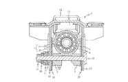
図3には、上部車体連結構造7内の軸直角断面を示す。インナーコラム5は、非鉄金属製のコラムハウジング8でほぼ被嵌されている。コラムハウジング8の下端部には軸線方向に沿ってスリットが形成され、そのスリットの両側下方に締付け部9が延設されている。チルトブラケット13は(図示しない)上方の車体取付部に取付けられ、コラムハウジング8を車幅方向両側から挟むようにして、二枚下方向きに延設される側壁部を有する。そして、一方のチルトブラケット側壁部13にクランプボルト16が装入され、その軸部が前記コラムハウジング8の2つの締付け部9を貫通し、締付け部9から突出したクランプボルト16を他方のチルトブラケット側壁部13から突出し、その先端ネジ部に、2枚のカム板11及びスラストベアリング18を介装して、ナット15が螺合されている。このうち、一方のカム板11はハンドルレバー17と一緒に回転するようになっており、ハンドルレバー17を例えば下方に回転するとカム板11の回転によるスラスト力で、カム板11とクランプボルト16の頭部とで2つの締付け部9がチルトブラケット側壁部13ごと図の内側に押付けられ、そのときコラムハウジング8のインナーコラム被嵌部に生じる締付け力でインナーコラム5が挟持され、所謂クランプされる。一方、ハンドルレバー17を例えば上方に回転するとカム板11の回転によるスラスト力が解除され、カム板11とクランプボルト16の頭部による締付け部9の押圧が解除され、コラムハウジング8のインナーコラム被嵌部によるインナーコラム5の締付け力が弱まり、アンクランプされる。
FIG. 3 shows a cross section perpendicular to the axis in the upper vehicle body connection structure 7. The
ピボットブラケット12には、車幅方向の軸線を有するピン10が設けられており、ピボットブラケット12ごと、つまりコラムハウジング8、インナーコラム5、ステアリングシャフト2も一緒にピン10の軸線周りに回転可能であり、これによりのアンクランプ時にはチルト調節、つまりステアリングホイール1の傾動が可能となる。また、コラムハウジング8の車幅方向両端部には軸先方向に長手なスライドガイド19が突設されており、アンクランプ時にあってテレスコピック調節、つまりステアリングホイール1の軸先方向への移動時には、スライドガイド19が2枚のチルトブラケット13の内側に摺接してガイドする。
The
本実施形態では、各チルトブラケット13の車幅方向内側面が当接するコラムハウジング8の締付け部9の車幅方向両外側に高摩擦係数材コーティング層20が設けられている。この高摩擦係数材コーティング層20は、例えば摩擦係数が1以上のゴム材料を500μm以下の厚さにディッピング又は塗布してコーティングしたものである。これにより、インナーコラム5のクランプ時、チルトブラケット13の内側面とコラムハウジング8の締付け部9との間に大きな摩擦力、即ち大きなクランプ力が生じ、ステアリングホイール1が強固に保持される。また、高摩擦係数材コーティング層20をコラムハウジング8の締付け部9の車幅方向両外側にコーティングにより一体的に設けたことにより、別部材の高摩擦係数部材を使用する必要がなく、その分だけ組立が容易になり、更にその分だけコストの低廉化が可能となる。ゴム材料自体は、周知のように、それほど強度の高い部材ではないが、コーティング層の厚さを500μm以下とすることにより、クランプボルト16の頭部及びカム板11の内側面による締付け時でも、座屈などによって所謂中折れするようなことがなく、十分な剛性が得られる。
In the present embodiment, the high friction coefficient
更には、本実施形態の高摩擦係数材コーティング層20には、例えばカーボンブラックを混入するなどして導電性を付与している。このように高摩擦係数材コーティング層20に導電性を付与することにより、例えばステアリングホイール1に装備したクラクションなどの電装品を正常に動作させることができるなど、用途が広がる。
また、アンクランプ時には、図4に示すように、クランプ時とは逆向きのカム板11のスラスト力に伴う変位によって、例えばコラムハウジング8の締付け部9とチルトブラケット13の内側面(実質的には高摩擦係数材コーティング層20とチルトブラケット13の内側面)との間(反対側の締付け部9とチルトブラケット13の内側面との間も同じ)に所定の間隔が形成され、高摩擦係数材コーティング層20による高摩擦力がチルトブラケット13の内側面との間に生じないように構成され、コラムハウジング8のスライドガイド19のみが2枚のチルトブラケット13の内側に摺接してガイドする。これにより、例えばテレスコピック調整時の調整力が必要以上に大きくなるのを防止することができる。また、このように構成することにより、長期間のクランプ状態でゴム部材からなる高摩擦係数コーティング層20がチルトブラケット13の内側面に固着したような場合に、それを強制的に離間することが可能となる。
Furthermore, the high friction coefficient
Further, at the time of unclamping, as shown in FIG. 4, for example, the tightening
図5は、本発明の車両用ステアリング装置の第2実施形態を示す軸直角断面図である。本実施形態の車両用ステアリング装置は、前記第1実施形態の車両用ステアリング装置とほぼ同様であり、図5に示す上部車体連結構造7の軸直角断面も、前記第1実施形態の図3の上部車体連結構造7とほぼ同様である。従って、同等の構成要件には、同等の符号を附し、その詳細な説明を省略する。本実施形態では、前述したゴム部材などからなる高摩擦係数材コーティング層20の形成位置が、前記第1実施形態の図3のものと異なる。本実施形態では、前記コラムハウジング8の締付け部9の車幅方向両外側に加え、同じくコラムハウジング8の車幅方向両端部に突設されたスライドガイド19の車幅方向両端部にも高摩擦係数材コーティング層20がコーティングにより一体的に形成されている。
FIG. 5 is a cross-sectional view perpendicular to the axis showing a second embodiment of the vehicle steering apparatus of the present invention. The vehicle steering device of the present embodiment is substantially the same as the vehicle steering device of the first embodiment, and the cross section perpendicular to the axis of the upper vehicle body connection structure 7 shown in FIG. 5 is the same as that of FIG. 3 of the first embodiment. This is substantially the same as the upper vehicle body connection structure 7. Accordingly, equivalent constituent elements are denoted by the same reference numerals, and detailed description thereof is omitted. In the present embodiment, the formation position of the high-friction coefficient
図6は、本発明の車両用ステアリング装置の第3実施形態を示す軸直角断面図である。本実施形態の車両用ステアリング装置は、前記第1実施形態の車両用ステアリング装置とほぼ同様であり、図6に示す上部車体連結構造7の軸直角断面も、前記第1実施形態の図3の上部車体連結構造7とほぼ同様である。従って、同等の構成要件には、同等の符号を附し、その詳細な説明を省略する。本実施形態では、前述したゴム部材などからなる高摩擦係数材コーティング層20の形成位置が、前記第1実施形態の図3のものと異なる。本実施形態では、2枚のチルトブラケット13の各車幅方向内側面、即ちコラムハウジング8側面に高摩擦係数材コーティング層20がコーティングにより一体的に形成されている。
FIG. 6 is a cross-sectional view perpendicular to the axis showing a third embodiment of the vehicle steering device of the present invention. The vehicle steering device of the present embodiment is substantially the same as the vehicle steering device of the first embodiment, and the cross section perpendicular to the axis of the upper vehicle body connection structure 7 shown in FIG. 6 is also the same as that of FIG. 3 of the first embodiment. This is substantially the same as the upper vehicle body connection structure 7. Accordingly, equivalent constituent elements are denoted by the same reference numerals, and detailed description thereof is omitted. In the present embodiment, the formation position of the high-friction coefficient
図7は、本発明の車両用ステアリング装置の第4実施形態を示す軸直角断面図である。本実施形態の車両用ステアリング装置は、前記第1実施形態の車両用ステアリング装置とほぼ同様であり、図7に示す上部車体連結構造7の軸直角断面も、前記第1実施形態の図3の上部車体連結構造7とほぼ同様である。従って、同等の構成要件には、同等の符号を附し、その詳細な説明を省略する。本実施形態では、前述したゴム部材などからなる高摩擦係数材コーティング層20の形成位置が、前記第1実施形態の図3のものと異なる。本実施形態では、前記コラムハウジング8の締付け部9の車幅方向両外側に加え、同じくコラムハウジング8の車幅方向両端部に突設されたスライドガイド19の車幅方向両端部にも、2枚のチルトブラケット13の各車幅方向内側面、即ちコラムハウジング8側面にも高摩擦係数材コーティング層20がコーティングにより一体的に形成されている。
FIG. 7 is a cross-sectional view perpendicular to the axis showing a fourth embodiment of the vehicle steering apparatus of the present invention. The vehicle steering device of the present embodiment is substantially the same as the vehicle steering device of the first embodiment, and the cross section perpendicular to the axis of the upper vehicle body connection structure 7 shown in FIG. 7 is also the same as that of FIG. 3 of the first embodiment. This is substantially the same as the upper vehicle body connection structure 7. Accordingly, equivalent constituent elements are denoted by the same reference numerals, and detailed description thereof is omitted. In the present embodiment, the formation position of the high-friction coefficient
図8は、本発明の車両用ステアリング装置の第5実施形態を示す軸直角断面図である。本実施形態の車両用ステアリング装置は、前記第1実施形態の車両用ステアリング装置とほぼ同様であり、図8に示す上部車体連結構造7の軸直角断面も、前記第1実施形態の図3の上部車体連結構造7とほぼ同様である。従って、同等の構成要件には、同等の符号を附し、その詳細な説明を省略する。本実施形態では、前述したゴム部材などからなる高摩擦係数材コーティング層20の形成位置が、前記第1実施形態の図3のものと異なる。本実施形態では、クランプボルト16の頭部の車幅方向内側面、即ちチルトブラケット13側面及びカム板11の車幅方向内側面、即ちチルトブラケット13側面に高摩擦係数材コーティング層20がコーティングにより一体的に形成されている。
FIG. 8 is a cross-sectional view perpendicular to the axis showing a fifth embodiment of the vehicle steering device of the present invention. The vehicle steering device of the present embodiment is substantially the same as the vehicle steering device of the first embodiment, and the cross section perpendicular to the axis of the upper vehicle body connection structure 7 shown in FIG. 8 is the same as that of FIG. 3 of the first embodiment. This is substantially the same as the upper vehicle body connection structure 7. Accordingly, equivalent constituent elements are denoted by the same reference numerals, and detailed description thereof is omitted. In the present embodiment, the formation position of the high-friction coefficient
図9は、本発明の車両用ステアリング装置の第6実施形態を示す軸直角断面図である。本実施形態の車両用ステアリング装置は、前記第1実施形態の車両用ステアリング装置とほぼ同様であり、図9に示す上部車体連結構造7の軸直角断面も、前記第1実施形態の図3の上部車体連結構造7とほぼ同様である。従って、同等の構成要件には、同等の符号を附し、その詳細な説明を省略する。本実施形態では、前述したゴム部材などからなる高摩擦係数材コーティング層20の形成位置が、前記第1実施形態の図3のものと異なる。本実施形態では、各チルトブラケット13の車幅方向外側面、即ちクランプボルト16の頭部側面及びカム板11の内側面側に高摩擦係数材コーティング層20がコーティングにより一体的に形成されている。
FIG. 9 is a cross-sectional view perpendicular to the axis showing a sixth embodiment of the vehicle steering device of the present invention. The vehicle steering device of the present embodiment is substantially the same as the vehicle steering device of the first embodiment, and the cross section perpendicular to the axis of the upper vehicle body connection structure 7 shown in FIG. 9 is the same as that of FIG. 3 of the first embodiment. This is substantially the same as the upper vehicle body connection structure 7. Accordingly, equivalent constituent elements are denoted by the same reference numerals, and detailed description thereof is omitted. In the present embodiment, the formation position of the high-friction coefficient
図10は、本発明の車両用ステアリング装置の第7実施形態を示す軸直角断面図である。本実施形態の車両用ステアリング装置は、前記第1実施形態の車両用ステアリング装置とほぼ同様であり、図10に示す上部車体連結構造7の軸直角断面も、前記第1実施形態の図3の上部車体連結構造7とほぼ同様である。従って、同等の構成要件には、同等の符号を附し、その詳細な説明を省略する。本実施形態では、前述したゴム部材などからなる高摩擦係数材コーティング層20の形成位置が、前記第1実施形態の図3のものと異なる。本実施形態では、クランプボルト16の頭部の内側面、即ちチルトブラケット13側面及びカム板11の内側面、即ちチルトブラケット13側面、及びチルトブラケット13の各車幅方向外側面、即ちクランプボルト16の頭部側面及びカム板11の内側面側に高摩擦係数材コーティング層20がコーティングにより一体的に形成されている。
FIG. 10 is a cross-sectional view perpendicular to the axis showing a seventh embodiment of the vehicle steering apparatus of the present invention. The vehicle steering device of the present embodiment is substantially the same as the vehicle steering device of the first embodiment, and the cross section perpendicular to the axis of the upper vehicle body connection structure 7 shown in FIG. 10 is the same as that of FIG. 3 of the first embodiment. This is substantially the same as the upper vehicle body connection structure 7. Accordingly, equivalent constituent elements are denoted by the same reference numerals, and detailed description thereof is omitted. In the present embodiment, the formation position of the high-friction coefficient
図11は、本発明の車両用ステアリング装置の第8実施形態を示す軸直角断面図である。本実施形態の車両用ステアリング装置の概略構成は、前記第1実施形態の図1に示すものと同様であり、ステアリングシャフトの概略構成も、前記第1実施形態の図2に示すものと同様である。本実施形態の車両用ステアリング装置では、インナーコラムを支持する上部車体連結構造の構成が、前記前記第1実施形態の図3の上部車体連結構造7の構成と少し異なる。しかしながら、同等の構成も多いので、それら同等の構成要件には、同等の符号を附し、その詳細な説明を省略する。具体的には、前記第1実施形態の非鉄金属製のコラムハウジングが、鉄製のアウターコラム22に変更され、全体で鉄製のステアリングコラム構造となっている。
FIG. 11 is a cross-sectional view perpendicular to the axis showing the eighth embodiment of the vehicle steering apparatus of the present invention. The schematic configuration of the vehicle steering device of the present embodiment is the same as that shown in FIG. 1 of the first embodiment, and the schematic configuration of the steering shaft is the same as that shown in FIG. 2 of the first embodiment. is there. In the vehicle steering device of the present embodiment, the configuration of the upper vehicle body connection structure that supports the inner column is slightly different from the configuration of the upper vehicle body connection structure 7 of FIG. 3 of the first embodiment. However, since there are many equivalent configurations, the same components are denoted by the same reference numerals, and detailed description thereof is omitted. Specifically, the nonferrous metal column housing of the first embodiment is changed to an iron
インナーコラム5には、同じく円筒状のもう一つのアウターコラム22が被嵌され、このアウターコラム22が、逆U字状の金属製U字ブラケット23の円弧部に覆われている。U字ブラケット23の2つの垂下部25の各内側には、アウターコラム22の車幅方向両側下方から当該アウターコラム22に当接するクランプブラケット24が設けられている。クランプボルト16は、2つのクランプブラケット24を通過するようにして、U字ブラケット23の2つの垂下部25及び2枚のチルトブラケット13に挿通されている。
The
従って、本実施形態では、ハンドルレバー17を例えば下方に回転するとカム板11の回転によるスラスト力により、カム板11とクランプボルト16の頭部とでU字ブラケット23の2つの垂下部25がチルトブラケット13ごと図の内側に押付けられ、そのときU字ブラケット23の円弧部とクランプブラケット24とに生じる締付け力でインナーコラム5がアウターコラム22ごと挟持され、所謂クランプされる。一方、ハンドルレバー17を例えば上方に回転するとカム板11の回転によるスラスト力が解除され、カム板11とクランプボルト16の頭部による垂下部25の押圧が解除され、U字ブラケット23とクランプブラケット24とによる前記締付け力が弱まり、アンクランプされる。アンクランプ時のテレスコピック調節時は、アウターコラム22がクランプブラケット24によってスライドガイドされる。
Therefore, in this embodiment, when the handle lever 17 is rotated downward, for example, the two hanging
そして、本実施形態では、U字ブラケット23の2つの垂下部25の車幅方向外側面に、前記第1実施形態と同様に、ゴム部材などからなる高摩擦係数材コーティング層20がコーティングによってU字ブラケット23と一体的に設けられている。高摩擦係数材コーティング層20の特徴は、前記第1実施形態と同様である。これにより、クランプ時、チルトブラケット13の車幅方向内側面とU字ブラケット23の垂下部25との間に大きな摩擦力、即ち大きなクランプ力が生じ、ステアリングホイール1が強固に保持される。
In the present embodiment, the high friction coefficient
また、アンクランプ時には、クランプ時とは逆向きのカム板11のスラスト力に伴う変位によって、U字ブラケット23の各垂下部25とチルトブラケット13の車幅方向内側面との間(実質的には高摩擦係数材コーティング層20とチルトブラケット13の内側面との間)に所定の間隔が形成され、高摩擦係数材コーティング層20による高摩擦力がチルトブラケット13との間に生じないように構成され、U字ブラケット23のクランプブラケット24のみがアウターコラム22の外周に摺接してガイドする。これにより、例えばテレスコピック調整時の調整力が必要以上に大きくなるのを防止することができる。
Further, at the time of unclamping, due to the displacement accompanying the thrust force of the
なお、前記第8実施形態では、U字ブラケット23の2つの垂下部25の車幅方向両外側に高摩擦係数材コーティング層20を設けたが、高摩擦係数材コーティング層20の形成部位はこれに限定されるものではなく、例えばチルトブラケット13の車幅方向内側面に設けたり、或いはU字ブラケット23の2つの垂下部25の車幅方向両外側とチルトブラケット13の車幅方向内側面との双方に設けたりしてもよい。即ち、本発明では、ステアリングホイールの位置調整時に相対移動する部材のクランプ時接触面の何れか一方又は双方に高摩擦係数材を一体的に施せばよい。
また、本発明の車両用ステアリング装置が適用されるステアリング装置の構成自体も、前記に限定されるものではなく、車両用ステアリング装置全般に広く展開することができる。
In the eighth embodiment, the high-friction coefficient
Further, the configuration itself of the steering device to which the vehicle steering device of the present invention is applied is not limited to the above, and can be widely applied to all vehicle steering devices.
1はステアリングホイール
2はステアリングシャフト
3は自在継手
4はインターミディエイトシャフト
5はインナーコラム
6は下部車体連結構造
7は上部車体連結構造
8はコラムハウジング
9は締付け部
10はピン
11はカム板
12はピボットブラケット
13はチルトブラケット
14はインナーチューブ
15はナット
16はクランプボルト
17はハンドルレバー
18はスラストベアリング
19はスライドガイド
20は高摩擦係数材コーティング層
21はベアリング
22はアウターコラム
23はU字ブラケット
24はクランプブラケット
25は垂下部
1 is a
Claims (6)
Priority Applications (1)
| Application Number | Priority Date | Filing Date | Title |
|---|---|---|---|
| JP2009185712A JP5509721B2 (en) | 2009-08-10 | 2009-08-10 | Vehicle steering device |
Applications Claiming Priority (1)
| Application Number | Priority Date | Filing Date | Title |
|---|---|---|---|
| JP2009185712A JP5509721B2 (en) | 2009-08-10 | 2009-08-10 | Vehicle steering device |
Publications (3)
| Publication Number | Publication Date |
|---|---|
| JP2011037357A JP2011037357A (en) | 2011-02-24 |
| JP2011037357A5 JP2011037357A5 (en) | 2012-06-07 |
| JP5509721B2 true JP5509721B2 (en) | 2014-06-04 |
Family
ID=43765613
Family Applications (1)
| Application Number | Title | Priority Date | Filing Date |
|---|---|---|---|
| JP2009185712A Expired - Fee Related JP5509721B2 (en) | 2009-08-10 | 2009-08-10 | Vehicle steering device |
Country Status (1)
| Country | Link |
|---|---|
| JP (1) | JP5509721B2 (en) |
Families Citing this family (5)
| Publication number | Priority date | Publication date | Assignee | Title |
|---|---|---|---|---|
| JP2011157015A (en) * | 2010-02-02 | 2011-08-18 | Fuji Kiko Co Ltd | Steering column device |
| KR101563705B1 (en) * | 2013-05-08 | 2015-10-28 | 한국델파이주식회사 | Steering column for vehicle |
| EP3257722B1 (en) | 2015-05-19 | 2019-03-27 | NSK Ltd. | Steering device |
| WO2016186149A1 (en) * | 2015-05-19 | 2016-11-24 | 日本精工株式会社 | Steering device |
| JP6680571B2 (en) * | 2016-03-04 | 2020-04-15 | 株式会社山田製作所 | Steering device |
Family Cites Families (7)
| Publication number | Priority date | Publication date | Assignee | Title |
|---|---|---|---|---|
| JPH0511105Y2 (en) * | 1988-01-29 | 1993-03-18 | ||
| JPH06293273A (en) * | 1993-03-09 | 1994-10-21 | Mazda Motor Corp | Control device for vehicle |
| JP2003118595A (en) * | 2001-08-06 | 2003-04-23 | Nsk Ltd | Vehicular steering device and its manufacturing method |
| JP2005195120A (en) * | 2004-01-08 | 2005-07-21 | Nsk Ltd | Vehicle steering expansion shaft |
| JP4333372B2 (en) * | 2004-01-13 | 2009-09-16 | 日本精工株式会社 | Tilt position adjustable steering column device |
| JP2008195260A (en) * | 2007-02-14 | 2008-08-28 | Nissan Motor Co Ltd | Elastic coupling structure for steering and steering device |
| JP5104068B2 (en) * | 2007-06-29 | 2012-12-19 | 日本精工株式会社 | Position adjustment type steering device |
-
2009
- 2009-08-10 JP JP2009185712A patent/JP5509721B2/en not_active Expired - Fee Related
Also Published As
| Publication number | Publication date |
|---|---|
| JP2011037357A (en) | 2011-02-24 |
Similar Documents
| Publication | Publication Date | Title |
|---|---|---|
| EP2923922B1 (en) | Steering Device | |
| JP5788829B2 (en) | Steering device | |
| JP5428582B2 (en) | Steering device | |
| JP5375996B2 (en) | Steering device | |
| EP2923919B1 (en) | Steering device | |
| KR101031627B1 (en) | Steering column assembly | |
| JP5528868B2 (en) | Steering device | |
| EP2535239A1 (en) | Steering apparatus | |
| JP5050550B2 (en) | Steering device | |
| JP5509721B2 (en) | Vehicle steering device | |
| US8091449B2 (en) | Steering apparatus | |
| JP5408367B1 (en) | Shock absorbing steering device | |
| JP2007099260A (en) | Steering device | |
| JP5233150B2 (en) | Steering device | |
| JP5167995B2 (en) | Steering device | |
| JP5181584B2 (en) | Steering device | |
| JP2006168492A (en) | Steering device | |
| JP2006264424A (en) | Steering device | |
| WO2015114991A1 (en) | Steering device | |
| JP6575803B2 (en) | Steering device | |
| JP6759746B2 (en) | Steering device | |
| JP2007038822A (en) | Steering device | |
| JP6668619B2 (en) | Telescopic steering column device | |
| JP5609812B2 (en) | Steering device | |
| WO2016114223A1 (en) | Steering device |
Legal Events
| Date | Code | Title | Description |
|---|---|---|---|
| RD04 | Notification of resignation of power of attorney |
Free format text: JAPANESE INTERMEDIATE CODE: A7424 Effective date: 20111216 |
|
| A521 | Request for written amendment filed |
Free format text: JAPANESE INTERMEDIATE CODE: A523 Effective date: 20120420 |
|
| A621 | Written request for application examination |
Free format text: JAPANESE INTERMEDIATE CODE: A621 Effective date: 20120420 |
|
| A977 | Report on retrieval |
Free format text: JAPANESE INTERMEDIATE CODE: A971007 Effective date: 20130415 |
|
| A131 | Notification of reasons for refusal |
Free format text: JAPANESE INTERMEDIATE CODE: A131 Effective date: 20130423 |
|
| A521 | Request for written amendment filed |
Free format text: JAPANESE INTERMEDIATE CODE: A523 Effective date: 20130619 |
|
| A131 | Notification of reasons for refusal |
Free format text: JAPANESE INTERMEDIATE CODE: A131 Effective date: 20130709 |
|
| A521 | Request for written amendment filed |
Free format text: JAPANESE INTERMEDIATE CODE: A523 Effective date: 20130828 |
|
| TRDD | Decision of grant or rejection written | ||
| A01 | Written decision to grant a patent or to grant a registration (utility model) |
Free format text: JAPANESE INTERMEDIATE CODE: A01 Effective date: 20140225 |
|
| A61 | First payment of annual fees (during grant procedure) |
Free format text: JAPANESE INTERMEDIATE CODE: A61 Effective date: 20140310 |
|
| R150 | Certificate of patent or registration of utility model |
Ref document number: 5509721 Country of ref document: JP Free format text: JAPANESE INTERMEDIATE CODE: R150 |
|
| LAPS | Cancellation because of no payment of annual fees |