JP5506552B2 - Control device for vibration actuator and control method for vibration actuator - Google Patents
Control device for vibration actuator and control method for vibration actuator Download PDFInfo
- Publication number
- JP5506552B2 JP5506552B2 JP2010130156A JP2010130156A JP5506552B2 JP 5506552 B2 JP5506552 B2 JP 5506552B2 JP 2010130156 A JP2010130156 A JP 2010130156A JP 2010130156 A JP2010130156 A JP 2010130156A JP 5506552 B2 JP5506552 B2 JP 5506552B2
- Authority
- JP
- Japan
- Prior art keywords
- frequency
- vibrator
- frequency range
- vibration type
- ellipticity
- Prior art date
- Legal status (The legal status is an assumption and is not a legal conclusion. Google has not performed a legal analysis and makes no representation as to the accuracy of the status listed.)
- Active
Links
- 238000000034 method Methods 0.000 title claims description 25
- 238000001514 detection method Methods 0.000 claims description 15
- 230000007423 decrease Effects 0.000 description 6
- 238000010586 diagram Methods 0.000 description 6
- 238000005452 bending Methods 0.000 description 5
- 230000003247 decreasing effect Effects 0.000 description 5
- 238000006243 chemical reaction Methods 0.000 description 4
- 239000007769 metal material Substances 0.000 description 4
- 238000013459 approach Methods 0.000 description 2
- 230000010287 polarization Effects 0.000 description 2
- 230000006870 function Effects 0.000 description 1
- 238000010408 sweeping Methods 0.000 description 1
Images


Classifications
-
- H—ELECTRICITY
- H02—GENERATION; CONVERSION OR DISTRIBUTION OF ELECTRIC POWER
- H02N—ELECTRIC MACHINES NOT OTHERWISE PROVIDED FOR
- H02N2/00—Electric machines in general using piezoelectric effect, electrostriction or magnetostriction
- H02N2/02—Electric machines in general using piezoelectric effect, electrostriction or magnetostriction producing linear motion, e.g. actuators; Linear positioners ; Linear motors
- H02N2/06—Drive circuits; Control arrangements or methods
-
- H—ELECTRICITY
- H02—GENERATION; CONVERSION OR DISTRIBUTION OF ELECTRIC POWER
- H02N—ELECTRIC MACHINES NOT OTHERWISE PROVIDED FOR
- H02N2/00—Electric machines in general using piezoelectric effect, electrostriction or magnetostriction
- H02N2/0005—Electric machines in general using piezoelectric effect, electrostriction or magnetostriction producing non-specific motion; Details common to machines covered by H02N2/02 - H02N2/16
- H02N2/001—Driving devices, e.g. vibrators
- H02N2/0015—Driving devices, e.g. vibrators using only bending modes
-
- H—ELECTRICITY
- H02—GENERATION; CONVERSION OR DISTRIBUTION OF ELECTRIC POWER
- H02N—ELECTRIC MACHINES NOT OTHERWISE PROVIDED FOR
- H02N2/00—Electric machines in general using piezoelectric effect, electrostriction or magnetostriction
- H02N2/0005—Electric machines in general using piezoelectric effect, electrostriction or magnetostriction producing non-specific motion; Details common to machines covered by H02N2/02 - H02N2/16
- H02N2/0075—Electrical details, e.g. drive or control circuits or methods
- H02N2/008—Means for controlling vibration frequency or phase, e.g. for resonance tracking
-
- H—ELECTRICITY
- H02—GENERATION; CONVERSION OR DISTRIBUTION OF ELECTRIC POWER
- H02N—ELECTRIC MACHINES NOT OTHERWISE PROVIDED FOR
- H02N2/00—Electric machines in general using piezoelectric effect, electrostriction or magnetostriction
- H02N2/02—Electric machines in general using piezoelectric effect, electrostriction or magnetostriction producing linear motion, e.g. actuators; Linear positioners ; Linear motors
- H02N2/026—Electric machines in general using piezoelectric effect, electrostriction or magnetostriction producing linear motion, e.g. actuators; Linear positioners ; Linear motors by pressing one or more vibrators against the driven body
-
- H—ELECTRICITY
- H02—GENERATION; CONVERSION OR DISTRIBUTION OF ELECTRIC POWER
- H02N—ELECTRIC MACHINES NOT OTHERWISE PROVIDED FOR
- H02N2/00—Electric machines in general using piezoelectric effect, electrostriction or magnetostriction
- H02N2/02—Electric machines in general using piezoelectric effect, electrostriction or magnetostriction producing linear motion, e.g. actuators; Linear positioners ; Linear motors
- H02N2/06—Drive circuits; Control arrangements or methods
- H02N2/062—Small signal circuits; Means for controlling position or derived quantities, e.g. for removing hysteresis
-
- H—ELECTRICITY
- H02—GENERATION; CONVERSION OR DISTRIBUTION OF ELECTRIC POWER
- H02N—ELECTRIC MACHINES NOT OTHERWISE PROVIDED FOR
- H02N2/00—Electric machines in general using piezoelectric effect, electrostriction or magnetostriction
- H02N2/10—Electric machines in general using piezoelectric effect, electrostriction or magnetostriction producing rotary motion, e.g. rotary motors
- H02N2/103—Electric machines in general using piezoelectric effect, electrostriction or magnetostriction producing rotary motion, e.g. rotary motors by pressing one or more vibrators against the rotor
-
- H—ELECTRICITY
- H02—GENERATION; CONVERSION OR DISTRIBUTION OF ELECTRIC POWER
- H02N—ELECTRIC MACHINES NOT OTHERWISE PROVIDED FOR
- H02N2/00—Electric machines in general using piezoelectric effect, electrostriction or magnetostriction
- H02N2/10—Electric machines in general using piezoelectric effect, electrostriction or magnetostriction producing rotary motion, e.g. rotary motors
- H02N2/14—Drive circuits; Control arrangements or methods
- H02N2/142—Small signal circuits; Means for controlling position or derived quantities, e.g. speed, torque, starting, stopping, reversing
Landscapes
- General Electrical Machinery Utilizing Piezoelectricity, Electrostriction Or Magnetostriction (AREA)
Description
本発明は、振動型アクチュエータの制御装置及び振動型アクチュエータの制御方法に関するものである。 The present invention relates to a vibration actuator control apparatus and a vibration actuator control method.
従来より、板状の振動子の所定の質点に楕円運動を生じさせ、被駆動体を駆動する振動波アクチュエータの提案がなされている。
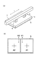
板状の振動子を有する振動型アクチュエータの基本的な構成としては、特許文献1に示すような構成が知られている。図8(a)は、特許文献1の振動型アクチュエータの基本的な構成の一例を示す外観斜視図である。
図8(a)に示すように、この振動型アクチュエータの振動子は、矩形の板状に形成された金属材料から成る弾性体4を備え、弾性体4の裏面には圧電素子(電気−機械エネルギー変換素子)5が接合されている。弾性体4の上面の所定位置には、複数の突起部6が設けられている。
この構成によれば、圧電素子5に交流電圧を印加することにより、弾性体4の長辺方向における2次の屈曲振動と、弾性体4の短辺方向における1次の屈曲振動とが同時に発生し、突起部6に楕円運動が励起される。
そして、突起部6の上部(接触部)に被駆動体7を加圧接触させることにより、被駆動体7を突起部6の楕円運動によって直線的に駆動することができるようになっている。つまり、突起部6がこの振動子の駆動部として作用する。
Conventionally, there has been proposed a vibration wave actuator that causes an elliptic motion to occur at a predetermined mass point of a plate-like vibrator and drives a driven body.
As a basic configuration of a vibration type actuator having a plate-like vibrator, a configuration as shown in Patent Document 1 is known. FIG. 8A is an external perspective view showing an example of a basic configuration of the vibration type actuator of Patent Document 1. FIG.
As shown in FIG. 8A, the vibrator of the vibration type actuator includes an
According to this configuration, by applying an AC voltage to the
The driven
図8(b)は、図8(a)に示した振動型アクチュエータにおける圧電素子5の分極領域の一例を示す模式図である。
また、図9(a)、(b)は、弾性体4の振動モードを示す斜視図であり、図9(c)は、弾性体4の突起部6に励起する楕円運動を説明するための説明図である。
上記圧電素子5は、図8(b)に示すように、分極処理されており、2つの電極A1、A2を備えている。
上記2つの電極A1、A2に同相の交流電圧V1、V2を印加することにより、上記矩形の弾性体4において長辺方向と平行な方向に延びた2本の節を有する1次の屈曲振動を励振する。これが図9(a)に示す第1の振動モードとなる。
また、2つの電極A1、A2に逆相の交流電圧V1、V2を印加することにより、矩形の弾性体4の短辺方向と平行な方向に延びた3本の節を有する2次の屈曲振動を励振する。これが図9(b)に示す第2の振動モードとなる。
そして、上記第1の振動モードと第2の振動モードの組み合わせにより突起部6に楕円運動を励振し、このとき、突起部6に被駆動体を加圧接触させると、被駆動体を直線的に駆動することができるようになっている。
ここで、図9(a)に示す第1の振動モードによって、突起部6には、被駆動体と加圧接触する接触部の面(以下、接触面と記す。)と垂直な方向に変位する振幅(以下、Z軸振幅と記す。)が励起される。
また、図9(b)に示す第2の振動モードによって、突起部6には、接触面と平行な方向に変位する振幅(以下、X軸振幅と記す。)が励起される。
上記第1の振動モードと第2の振動モードの2つの振幅モードを組み合わせることにより、所定の突起部6に図9(c)に示すように楕円運動が励起することができる。以下Z軸振幅とX軸振幅の大きさの比を本明細書では楕円運動の楕円比と記す。
FIG. 8B is a schematic diagram illustrating an example of a polarization region of the
FIGS. 9A and 9B are perspective views showing vibration modes of the
The
By applying in-phase AC voltages V1 and V2 to the two electrodes A1 and A2, a primary bending vibration having two nodes extending in a direction parallel to the long side direction in the rectangular
Further, by applying AC voltages V1 and V2 having opposite phases to the two electrodes A1 and A2, a secondary bending vibration having three nodes extending in a direction parallel to the short side direction of the rectangular
Then, when the elliptical motion is excited in the protrusion 6 by the combination of the first vibration mode and the second vibration mode, and the driven body is brought into pressure contact with the protrusion 6 at this time, the driven body is linearly moved. Can be driven to.
Here, according to the first vibration mode shown in FIG. 9A, the protrusion 6 is displaced in a direction perpendicular to the surface of the contact portion (hereinafter referred to as a contact surface) in pressure contact with the driven body. To be excited (hereinafter referred to as Z-axis amplitude).
Further, the second vibration mode shown in FIG. 9B excites the protrusion 6 with an amplitude that is displaced in a direction parallel to the contact surface (hereinafter referred to as X-axis amplitude).
By combining the two amplitude modes of the first vibration mode and the second vibration mode, elliptical motion can be excited in the predetermined protrusion 6 as shown in FIG. 9C. Hereinafter, the ratio of the magnitude of the Z-axis amplitude to the X-axis amplitude is referred to as the elliptic ratio of elliptical motion in this specification.
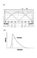
図10(a)は、2相の電圧V1、V2の位相差を−180度〜180度で変化させたときの第1の振動モード及び第2の振動モードの振幅を説明するためのグラフである。
分極された圧電素子5における2つの電極A1、A2に印加する2相の交流電圧V1、V2の位相差を−180度〜180度に変化させたときの、第1の振動モードと第2の振動モード(P2)の振幅は、それぞれ図10(a)のP1とP2に示すようになる。
同図の横軸が位相差を示し、縦軸が第1の振幅モードと第2の振幅モードの振幅を示している。
第1の振動モードと第2の振動モードの組み合わせにより突起部6に楕円運動が励起し、印加する交流電圧V1、V2の位相差を変更することにより、所定の突起部6の励起する楕円運動の楕円比を調整することができる。
FIG. 10A is a graph for explaining the amplitudes of the first vibration mode and the second vibration mode when the phase difference between the two-phase voltages V1 and V2 is changed from −180 degrees to 180 degrees. is there.
The first vibration mode and the second vibration mode when the phase difference between the two-phase AC voltages V1 and V2 applied to the two electrodes A1 and A2 in the polarized
In the figure, the horizontal axis indicates the phase difference, and the vertical axis indicates the amplitude of the first amplitude mode and the second amplitude mode.
The elliptical motion is excited in the protrusion 6 by the combination of the first vibration mode and the second vibration mode, and the elliptical motion that the predetermined protrusion 6 is excited by changing the phase difference between the applied AC voltages V1 and V2. The ellipse ratio can be adjusted.
図10(a)の下部に、横軸の位相差に応じた楕円形状を示す。そして、交流電圧V1、V2の位相差の正負の符号を切り替えることにより、直線的に駆動する振動型アクチュエータの駆動方向を切り替えることができる。
さらに、位相差を任意の値から正負の符号を含めて連続的に切り替える(例えば、位相差を正負の符号を含めて90度から−90度まで連続的に変更する)ことにより、駆動方向と速度が連続的に変化させることが可能になる。
駆動速度においては図10(b)に示すように共振周波数を速度のピークとし、共振周波数よりも高周波数側ではなだらかに駆動速度が減少し、かつ低周波数側では急激に速度が減少する現象(以下、崖落ち現象と記す)が生じてしまう。
また、圧電素子に印加する交流電圧の周波数を共振周波数に近づけることにより、速度を速くすることができ、印加する交流電圧の周波数を共振周波数から遠ざけることにより、速度を遅くすることができることが一般的に知られている。
このような振動型アクチュエータにおいて、振動子を複数用いることにより駆動力を高めた装置を構成することが可能である。
An elliptical shape corresponding to the phase difference on the horizontal axis is shown in the lower part of FIG. Then, by switching the sign of the phase difference between the AC voltages V1 and V2, the driving direction of the vibration type actuator that is driven linearly can be switched.
Furthermore, the phase difference is continuously switched from an arbitrary value including a positive / negative sign (for example, the phase difference is continuously changed from 90 degrees to −90 degrees including a positive / negative sign) to thereby change the driving direction. The speed can be changed continuously.
In the driving speed, as shown in FIG. 10B, the resonance frequency is a peak of the speed, the driving speed is gently decreased on the higher frequency side than the resonant frequency, and the speed is rapidly decreased on the lower frequency side ( (Hereinafter referred to as a cliff fall phenomenon).
In addition, the speed can be increased by bringing the frequency of the alternating voltage applied to the piezoelectric element closer to the resonance frequency, and the speed can be decreased by moving the frequency of the applied alternating voltage away from the resonance frequency. Known.
In such a vibration type actuator, it is possible to configure a device having an increased driving force by using a plurality of vibrators.
しかしながら、複数の振動子を用いて被駆動体を駆動するように振動型アクチュエータを構成する場合、つぎのような課題が生じる。
振動型アクチュエータの制御装置の回路構成を簡単にするため、複数のそれぞれの振動子に共通の周波数を印加する場合、各々の振動子の共振周波数にズレがあると、動作が不安定になる。このため、不安定な部分を使用せずに駆動することが必要がある。
However, when a vibration type actuator is configured to drive a driven body using a plurality of vibrators, the following problems occur.
In order to simplify the circuit configuration of the control device for the vibration type actuator, when a common frequency is applied to each of the plurality of vibrators, the operation becomes unstable if there is a deviation in the resonance frequency of each vibrator. For this reason, it is necessary to drive without using an unstable part.
本発明は、上記課題に鑑み、複数の振動子を用いて被駆動体を駆動するように構成するに当たり、それぞれの振動子の共振周波数にズレがあっても、安定して駆動することが可能となる振動型アクチュエータの制御装置及び制御方法の提供を目的とする。 In view of the above problems, the present invention is configured to drive a driven body using a plurality of vibrators, and can be driven stably even if there is a deviation in the resonance frequency of each vibrator. An object of the present invention is to provide a control device and a control method for a vibration type actuator.
本発明は、つぎのように構成した振動型アクチュエータの制御装置及び振動型アクチュエータの制御方法を提供するものである。
本発明の振動型アクチュエータの制御装置は、複数の振動子に共通の交流信号を印加することにより前記複数の振動子の接触部に楕円運動を生じさせ、前記楕円運動により前記接触部に接触する被駆動体を前記複数の振動子に対して相対移動させる振動型アクチュエータの制御装置であって、
前記交流信号の駆動周波数を設定する周波数決定手段を備え、
前記周波数決定手段は、振動子毎に設定された楕円比変更周波数範囲が重複する周波数範囲内で、前記楕円運動の楕円比を変化させる際の前記交流信号の周波数を設定し、
前記楕円比変更周波数範囲は、
前記楕円比を変化させた時の最大の共振周波数を下限値とし、前記下限値よりも高い周波数であり前記被駆動体が相対移動する最大の周波数を上限値とし、前記上限値と前記下限値の間の周波数範囲として前記振動子毎に設定されていることを特徴とする。
また、本発明の振動型アクチュエータの制御装置は、交流信号の駆動周波数を設定する周波数決定手段を備え、
前記交流信号は、振動型アクチュエータの少なくとも第1の振動子と第2の振動子のそれぞれの接触部の楕円運動を生成するための信号であり、
前記第1の振動子は、前記第1の振動子の接触部の楕円運動の楕円比を変更するための第1の周波数範囲を有し、
前記第2の振動子は、前記第2の振動子の接触部の楕円運動の楕円比を変更するための第2の周波数範囲を有し、
前記周波数決定手段は、前記第1の振動子と前記第2の振動子のそれぞれの楕円比を変更するように、前記交流信号の周波数を、前記第1の周波数範囲と前記第2の周波数範囲が重複する範囲内に設定することを特徴とする。
また、本発明の振動型アクチュエータの制御方法は、複数の振動子に共通の交流信号を印加することにより前記複数の振動子の接触部に楕円運動を生じさせ、前記楕円運動により前記接触部に接触する被駆動体を前記複数の振動子に対して相対移動させる振動型アクチュエータの制御方法であって、
振動子毎に設定された楕円比変更周波数範囲が重複する周波数範囲内で、前記楕円運動の楕円比を変化させる際の前記交流信号の周波数を設定するにあたり、
前記楕円比を変化させた時の最大の共振周波数を下限値とし、前記下限値よりも高い周波数であり前記被駆動体が相対移動する最大の周波数を上限値とし、前記上限値と前記下限値の間の周波数範囲を前記楕円比変更周波数範囲として前記振動子毎に設定することを特徴とする。
また、本発明の振動型アクチュエータの制御方法は、複数の振動子に共通の交流信号を印加することにより前記複数の振動子の接触部に楕円運動を生じさせ、前記楕円運動により前記接触部に接触する被駆動体を前記複数の振動子に対して相対移動させる振動型アクチュエータの制御方法であって、
交流信号の周波数を設定する周波数決定工程を有し、
前記交流信号は、振動型アクチュエータの少なくとも第1の振動子と第2の振動子のそれぞれの接触部の楕円運動を生成するための信号であり、
前記第1の振動子は、前記第1の振動子の接触部の楕円運動の楕円比を変更するための第1の周波数範囲を有し、
前記第2の振動子は、前記第2の振動子の接触部の楕円運動の楕円比を変更するための第2の周波数範囲を有し、
前記周波数決定工程は、前記第1の振動子と前記第2の振動子のそれぞれの楕円比を変更するように、前記交流信号の周波数を、前記第1の周波数範囲と前記第2の周波数範囲が重複する範囲内に設定する工程を有することを特徴とする。
The present invention provides a vibration actuator control apparatus and a vibration actuator control method configured as follows.
The control device for the vibration type actuator of the present invention causes an elliptical motion to occur in the contact portion of the plurality of transducers by applying a common AC signal to the plurality of transducers, and contacts the contact portion by the elliptical motion. A control device for a vibration type actuator for moving a driven body relative to the plurality of vibrators,
Comprising frequency determining means for setting the drive frequency of the AC signal;
The frequency determining means sets the frequency of the AC signal when changing the ellipticity of the elliptical motion within a frequency range where the ellipticity change frequency range set for each transducer overlaps,
The ellipticity change frequency range is
The maximum resonance frequency when changing the ellipticity ratio is set as a lower limit value, the maximum frequency that is higher than the lower limit value and the relative movement of the driven body is set as an upper limit value, and the upper limit value and the lower limit value The frequency range is set for each of the vibrators.
Further, the control device for the vibration type actuator of the present invention includes frequency determining means for setting the drive frequency of the AC signal,
The AC signal is a signal for generating an elliptical motion of each contact portion of at least the first vibrator and the second vibrator of the vibration type actuator,
The first vibrator has a first frequency range for changing the ellipticity of the elliptical motion of the contact portion of the first vibrator;
The second vibrator has a second frequency range for changing the ellipticity of the elliptical motion of the contact portion of the second vibrator;
The frequency determination means sets the frequency of the AC signal to the first frequency range and the second frequency range so as to change the elliptic ratio of each of the first vibrator and the second vibrator. Is set within the overlapping range.
Further, in the control method of the vibration type actuator of the present invention, an elliptical motion is generated in the contact portion of the plurality of transducers by applying a common AC signal to the plurality of transducers, and the contact portion is caused by the elliptical motion. A control method of a vibration type actuator for relatively moving a driven body in contact with the plurality of vibrators,
In setting the frequency of the AC signal when changing the ellipticity ratio of the elliptical motion within the frequency range where the ellipticity change frequency range set for each transducer overlaps,
The maximum resonance frequency when changing the ellipticity ratio is set as a lower limit value, the maximum frequency that is higher than the lower limit value and the relative movement of the driven body is set as an upper limit value, and the upper limit value and the lower limit value The frequency range between is set as the ellipticity ratio changing frequency range for each transducer.
Further, in the control method of the vibration type actuator of the present invention, an elliptical motion is generated in the contact portion of the plurality of transducers by applying a common AC signal to the plurality of transducers, and the contact portion is caused by the elliptical motion. A control method of a vibration type actuator for relatively moving a driven body in contact with the plurality of vibrators,
A frequency determining step for setting the frequency of the AC signal;
The AC signal is a signal for generating an elliptical motion of each contact portion of at least the first vibrator and the second vibrator of the vibration type actuator,
The first vibrator has a first frequency range for changing the ellipticity of the elliptical motion of the contact portion of the first vibrator;
The second vibrator has a second frequency range for changing the ellipticity of the elliptical motion of the contact portion of the second vibrator;
In the frequency determination step, the frequency of the AC signal is changed between the first frequency range and the second frequency range so as to change the elliptic ratio of each of the first vibrator and the second vibrator. It has the process of setting in the range which overlaps.
本発明によれば、複数の振動子を用いて被駆動体を駆動する装置を構成するに当たり、
それぞれの振動子の共振周波数にズレがあっても、安定して駆動することが可能となる振動型アクチュエータの制御装置及び制御方法を実現することができる。
According to the present invention, in configuring an apparatus for driving a driven body using a plurality of vibrators,
Even if there is a deviation in the resonance frequency of each vibrator, it is possible to realize a control device and control method for a vibration type actuator that can be driven stably.
以下、本発明の実施の形態について、図面を参照しながら説明する。
[第1の実施形態]
本発明の第1の実施形態における振動型アクチュエータの制御装置の構成を、図1を用いて説明する。
本実施形態の振動型アクチュエータは、少なくとも電気−機械エネルギー変換素子と弾性体とを有する振動子を複数備えている。
そして、前記複数の振動子におけるそれぞれの前記電気−機械エネルギー変換素子に対し共通の駆動周波数による交流信号を印加することによって、前記複数の振動子の接触部を介して接触している被駆動体を駆動するように構成されている。
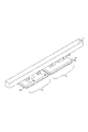
図1は、2つの振動子により1つの被駆動体を相対駆動させる振動型アクチュエータであり、直線状に延びる被駆動体の長手方向に被駆動体を相対移動させるよう構成されている。これらの2つの振動子により、2倍の推力を発生させることができる。
図1に示す振動子8aと振動子8bは不図示のホルダにより一体となって被駆動体3と相対移動する構成とされている。
図1に示すように、この振動型アクチュエータの振動子8aは、矩形の板状に形成された金属材料から成る弾性体4aを備え、弾性体4aの裏面には圧電素子(電気−機械エネルギー変換素子)5aが接合されている。
弾性体4aの上面の所定位置には、2つの突起部6aが設けられている。
図1に示す振動子は突起部に楕円運動を生じさせ、突起部の上部(接触部)に摩擦接触する被駆動体を駆動する。同様に振動子8bは、弾性体4bには圧電素子5bが接合されており、弾性体4bの所定位置には2つの突起6bが設けられている。
Hereinafter, embodiments of the present invention will be described with reference to the drawings.
[First Embodiment]
The configuration of the control device for the vibration type actuator according to the first embodiment of the present invention will be described with reference to FIG.
The vibration type actuator of this embodiment includes a plurality of vibrators having at least an electro-mechanical energy conversion element and an elastic body.
And the to-be-driven body which is contacting via the contact part of the said several vibrator | oscillator by applying the alternating current signal by a common drive frequency with respect to each said electro-mechanical energy conversion element in these vibrator | oscillators It is comprised so that it may drive.
FIG. 1 shows a vibration type actuator that relatively drives one driven body by two vibrators, and is configured to relatively move the driven body in the longitudinal direction of the driven body that extends linearly. These two vibrators can generate twice as much thrust.
The vibrator 8a and the vibrator 8b shown in FIG. 1 are configured to move together with the driven body 3 by a holder (not shown).
As shown in FIG. 1, a vibrator 8a of the vibration actuator includes an elastic body 4a made of a metal material formed in a rectangular plate shape, and a piezoelectric element (electro-mechanical energy conversion) is provided on the back surface of the elastic body 4a. Element) 5a is joined.
Two protrusions 6a are provided at predetermined positions on the upper surface of the elastic body 4a.
The vibrator shown in FIG. 1 causes an elliptical motion in the protrusion, and drives a driven body that is in frictional contact with the upper portion (contact portion) of the protrusion. Similarly, in the vibrator 8b, a piezoelectric element 5b is bonded to the elastic body 4b, and two protrusions 6b are provided at predetermined positions of the elastic body 4b.
図1に示す、圧電素子5a、5bには図8(b)に示す2群の電極A1、A2が設けられており、圧電素子5a、5bは図8(b)の紙面方向に分極処理されている。
この構成による振動子は印加する2相の交流電圧(交流信号)の位相差を変更することにより、図1に示す突起部6a、6bに励起する楕円運動の楕円比を変更することができる。
The piezoelectric elements 5a and 5b shown in FIG. 1 are provided with two groups of electrodes A1 and A2 shown in FIG. 8B, and the piezoelectric elements 5a and 5b are polarized in the paper direction of FIG. 8B. ing.
The vibrator having this configuration can change the ellipticity of the elliptical motion excited in the protrusions 6a and 6b shown in FIG. 1 by changing the phase difference between the applied two-phase AC voltages (AC signals).
図1に示す振動子は、図10(b)に示すように、振動子の圧電素子に印加する交流電圧の駆動周波数を共振周波数に近づけることにより、速度を速くすることができる。
また、印加する交流電圧の周波数を共振周波数から遠ざけることにより、速度を遅くすることができる。
また、共振周波数を速度のピークとし、共振周波数よりも高周波数側ではなだらかに駆動速度が減少し、且つ低周波数側では急激に駆動速度が減少するような特性となる。
また、突起部6a、6bに励起する楕円運動のX軸振幅を大きくすることにより、被駆動体の移動速度を速くすることができる。
また、X軸振幅を小さくすると共に、Z軸振幅を所定の振幅に保つことにより、被駆動体の移動速度を安定的に遅くすることができる。
また、2相の交流電圧の位相差を切り替えることにより、被駆動体の相対移動の向きを切り替えることができる。
As shown in FIG. 10B, the vibrator shown in FIG. 1 can be increased in speed by bringing the drive frequency of the alternating voltage applied to the piezoelectric element of the vibrator close to the resonance frequency.
Further, the speed can be reduced by keeping the frequency of the applied AC voltage away from the resonance frequency.
Further, the resonance frequency is set to the peak of the speed, and the driving speed is gradually decreased on the higher frequency side than the resonance frequency, and the driving speed is rapidly decreased on the lower frequency side.
Moreover, the moving speed of the driven body can be increased by increasing the X-axis amplitude of the elliptical motion excited in the protrusions 6a and 6b.
Further, the moving speed of the driven body can be stably reduced by reducing the X-axis amplitude and keeping the Z-axis amplitude at a predetermined amplitude.
Further, the direction of relative movement of the driven body can be switched by switching the phase difference between the two-phase AC voltages.
上記図8(b)に示す、圧電素子5の電極V1、V2に対して印加する交流電圧の位相差を−180度〜180度で変化させたとき所定の突起部6a、6bに励起する楕円運動の楕円比を調整することができる。
図10(a)の下部に、横軸の位相差に応じた楕円形状を示す。
位相差を正負の符号を含めて90度から−90度まで連続的に変更することにより、駆動方向と速度が連続的に変化させることが可能になる。
上記の構成によって、図1の振動子8a、および8bそれぞれに振動を励振することにより、被駆動体(スライダ)3を駆動することが可能となる。
また、本発明の振動子は、上記形態に限られず、突起部にZ軸振幅を励起する振動モードの振動と、突起部にX軸振幅を励起する振動モードの振動と、の組み合わせにより突起部に楕円運動を生じさせる振動子であればよい。具体的には、上記形態の他に、振動子の長手方向の伸縮振動と曲げ振動とを組み合わせて突起部に楕円運動を生じさせる形態でもよい。
As shown in FIG. 8B, an ellipse that excites the predetermined protrusions 6a and 6b when the phase difference of the AC voltage applied to the electrodes V1 and V2 of the
An elliptical shape corresponding to the phase difference on the horizontal axis is shown in the lower part of FIG.
By continuously changing the phase difference from 90 degrees to -90 degrees including positive and negative signs, the driving direction and speed can be continuously changed.
With the above configuration, the driven body (slider) 3 can be driven by exciting the vibrators 8a and 8b in FIG.
Further, the vibrator of the present invention is not limited to the above-described form, and the projection portion is formed by a combination of vibration mode vibration that excites the Z-axis amplitude in the projection portion and vibration mode vibration that excites the X-axis amplitude in the projection portion. Any transducer that causes elliptical motion can be used. Specifically, in addition to the above-described form, an elliptical motion may be generated in the protrusion by combining the longitudinal vibration and bending vibration of the vibrator.
次に、図1に示す1つの振動子の駆動特性について説明する。
図2は、1つの振動子と1つの被駆動体で駆動した場合の、電極A1と電極A2(図8(b)参照)に印加する交流電圧の位相差と駆動周波数と駆動速度の関係を示すグラフである。例えば、図2に示すように、位相差が90度から0度に近づくほど、第2の振幅モードの振幅が小さくなることにより駆動速度が小さくなる。また、位相差が90度から0度に近づくほど、共振周波数が高くなる。
ここで位相差を変更する際の駆動特性を説明する。
例えば、位相差60度のときの共振周波数に値に駆動周波数を設定し、位相差を90度から低位相差側にシフトした場合、位相差90度から位相差60度までは共振周波数よりも高周波側で駆動しているため崖落ち現象は生じない。ところが、位相差を60度よりも小さくシフトさせると、突然崖落ち現象が発生することになる。つまり、位相差60度のときの共振周波数の値に駆動周波数を設定し、位相差を変更する際は位相差60度より低位相差側は不安定な動作となる。
しかしながら、位相差10度のときの共振周波数の値に駆動周波数を設定し、位相差を90度から低位相差側にシフトした場合、位相差90度から位相差10度までは位相差10度の共振周波数よりも高周波数側で駆動しているため崖落ち現象は生じない。
つまり、駆動周波数を固定して位相差を変更して駆動する場合、位相差が低い値の場合の共振周波数より高周波数側で駆動することが崖落ち現象の発生を少なくすることができる。
上述の位相差が0度の時の共振周波数24が最も高い共振周波数となるので、この周波数を位相差を変化させる制御を行う際の下限値とする。
Next, driving characteristics of one vibrator shown in FIG. 1 will be described.
FIG. 2 shows the relationship between the phase difference of the AC voltage applied to the electrodes A1 and A2 (see FIG. 8B), the drive frequency, and the drive speed when driven by one vibrator and one driven body. It is a graph to show. For example, as shown in FIG. 2, as the phase difference approaches 90 degrees from 0 degrees, the amplitude of the second amplitude mode decreases, and thus the driving speed decreases. Also, the resonance frequency increases as the phase difference approaches 90 degrees from 0 degrees.
Here, driving characteristics when changing the phase difference will be described.
For example, when the drive frequency is set to the resonance frequency when the phase difference is 60 degrees and the phase difference is shifted from 90 degrees to the low phase difference side, the phase difference from 90 degrees to the phase difference of 60 degrees is higher than the resonance frequency. Because it is driven on the side, there is no cliff fall phenomenon. However, when the phase difference is shifted to less than 60 degrees, a sudden cliff fall phenomenon occurs. That is, when the drive frequency is set to the value of the resonance frequency when the phase difference is 60 degrees and the phase difference is changed, the operation on the phase difference side lower than the phase difference of 60 degrees is unstable.
However, when the drive frequency is set to the value of the resonance frequency when the phase difference is 10 degrees and the phase difference is shifted from 90 degrees to the low phase difference side, the phase difference of 90 degrees from the phase difference of 90 degrees to the phase difference of 10 degrees Since it is driven at a frequency higher than the resonance frequency, no cliff fall phenomenon occurs.
That is, when driving by fixing the driving frequency and changing the phase difference, driving on the higher frequency side than the resonance frequency when the phase difference is a low value can reduce the occurrence of a cliff fall phenomenon.
Since the resonance frequency 24 when the phase difference is 0 degree is the highest resonance frequency, this frequency is set as a lower limit value when the control for changing the phase difference is performed.
つぎに、周波数を変更した際の駆動特性を説明する。
例えば、位相差を90度に設定した状態で、共振周波数より高周波数側に駆動周波数をスイープアップすると駆動速度が徐々に小さくなり、突然、駆動速度が下がり動作しなくなる部分23がある。このように、下限値よりも高周波数側であって、被駆動体が相対移動しなくなる周波数を、位相差制御の際の上限値とする。また、上限値としては、上記したスイープアップした際に被駆動体が動作しなくなる部分23ではなく、共振周波数より十分に高周波数側から駆動周波数をスイープダウンした場合に速度が急激に立ち上がる部分の周波数を上限値としても良い。つまり、本発明においては、スイープダウン又はスイープアップの際に、下限値よりも高周波数側であって被駆動体が相対移動しなくなる周波数を上限値に設定すればよい。
上述の周波数の上限値と下限値の間の周波数範囲を図2に示す楕円比変更周波数範囲と設定する。この楕円比変更の周波数範囲内で楕円比を変更することにより、崖落ち現象や駆動速度が下がり動作しなくなる部分を避けて駆動することができる。
Next, drive characteristics when the frequency is changed will be described.
For example, when the phase difference is set to 90 degrees and the drive frequency is swept up to a higher frequency than the resonance frequency, there is a portion 23 where the drive speed gradually decreases and the drive speed is suddenly lowered and no operation is performed. As described above, the frequency that is higher than the lower limit value and at which the driven body does not relatively move is set as the upper limit value in the phase difference control. In addition, the upper limit value is not the portion 23 where the driven body does not operate when sweeping up as described above, but the portion where the speed suddenly rises when the drive frequency is swept down from a frequency sufficiently higher than the resonance frequency. The frequency may be the upper limit value. That is, in the present invention, the frequency that is higher in frequency than the lower limit value and at which the driven body does not relatively move during the sweep down or sweep up may be set as the upper limit value.
A frequency range between the upper limit value and the lower limit value of the above-described frequency is set as an ellipticity ratio changing frequency range shown in FIG. By changing the elliptic ratio within the frequency range for changing the elliptic ratio, it is possible to drive while avoiding a cliff fall phenomenon or a portion where the driving speed decreases and the operation is stopped.
図3のブロック図を用いて、本実施形態における振動型アクチュエータの制御装置の構成について説明する。
この制御装置は、被駆動体の目標値を生成する位置指令生成手段17を有し、その出力側には、比較手段18を介して操作量決定手段22が接続されている。
比較手段18は、位置指令生成手段17から出力された目標値と、位置検出手段16から出力された被駆動体の現在位置とを比較する。
操作量決定手段22は、比較手段18の比較結果から、振動型アクチュエータの操作量eを演算する。
操作量決定手段22はPI制御器、またはPID制御器で構成されている。位置検出手段16は、被駆動体3の位置を検出するものであり、例えば、リニアスケールやエンコーダにて構成される。
振動子8aは、上記図1に示した構成の振動子であり、矩形の板状に形成された金属材料から成る弾性体4aの裏面に圧電素子5aが接合され、弾性体4aの表面に複数の突起部6aが設けられた振動子を備えている。
同様に、振動子8bは図1に示した構成の振動子であり、矩形の板状に形成された金属材料から成る弾性体4bの裏面に圧電素子5bが接合され、弾性体4bの表面に駆動部としての複数の突起部6bが設けられた振動子を備えている。
被駆動体3は、図1に示す被駆動体3であり、振動子8a及び振動子8bの出力側に被駆動体3が接続されている。
操作量決定手段22の出力側には、上記した楕円運動における楕円の比率を設定する楕円比決定手段19と、交流信号の周波数を設定する周波数決定手段20が接続されている。
With reference to the block diagram of FIG. 3, the configuration of the control device for the vibration type actuator in this embodiment will be described.
This control device has a position command generation means 17 for generating a target value of the driven body, and an operation amount determination means 22 is connected to the output side via a comparison means 18.
The
The operation
The operation
The vibrator 8a is a vibrator having the structure shown in FIG. 1, and a piezoelectric element 5a is bonded to the back surface of an elastic body 4a made of a metal material formed in a rectangular plate shape, and a plurality of pieces are formed on the surface of the elastic body 4a. The vibrator is provided with the protruding portion 6a.
Similarly, the vibrator 8b is a vibrator having the configuration shown in FIG. 1, and a piezoelectric element 5b is joined to the back surface of an elastic body 4b made of a metal material formed in a rectangular plate shape, and the surface of the elastic body 4b. A vibrator provided with a plurality of protrusions 6b as a drive unit is provided.
The driven body 3 is the driven body 3 shown in FIG. 1, and the driven body 3 is connected to the output side of the vibrator 8a and the vibrator 8b.
Connected to the output side of the manipulated
楕円比決定手段19は、操作量決定手段22の出力から、振動子8a、振動子8bの突起部に生成する楕円運動のX軸振幅とZ軸振幅の比率を設定し、その比率を実現する位相差を設定可能に構成されている。
駆動周波数決定手段20は操作量決定手段22の出力から、振動子8a、振動子8bに印加する交流電圧の駆動周波数を設定可能に構成されている。
さらに、楕円比決定手段19及び駆動周波数決定手段20の出力側が駆動信号生成手段21に接続されている。
駆動信号生成手段21は、周波数決定手段20で決定された周波数で、かつ楕円比決定手段19で決定された位相差を有する2相の交流信号を生成する。
駆動信号生成手段21の出力側には昇圧回路25が接続されている。昇圧回路25は駆動信号生成手段21で生成された2相の交流信号を昇圧し、昇圧された2相の交流信号は振動子8a、8bの圧電素子に印加する。
昇圧回路25は、電力増幅器、スイッチング素子、DC/DC回路、またはトランス回路で構成されてもよい。
The elliptical ratio determining means 19 sets the ratio of the X-axis amplitude and the Z-axis amplitude of the elliptical motion generated on the protrusions of the vibrator 8a and the vibrator 8b from the output of the operation
The drive
Further, the output sides of the ellipticity ratio determining means 19 and the drive
The drive
A booster circuit 25 is connected to the output side of the drive signal generating means 21. The booster circuit 25 boosts the two-phase AC signal generated by the
The booster circuit 25 may be configured by a power amplifier, a switching element, a DC / DC circuit, or a transformer circuit.
図4を用いて、本実施形態における楕円比決定手段19及び駆動周波数決定手段20の機能を説明する。
図4の中のグラフにおいて、横軸が操作量eであり、縦軸がそれぞれ位相差θ、駆動周波数frを表わしている。
操作量決定手段22から出力された操作量eを楕円比決定手段19の入力値とする。
そして、この入力値により、楕円比決定手段19がグラフで表された設定に基づいて楕円比を決定する。
駆動周波数決定手段20にも操作量決定手段22から出力された操作量eが入力されており、グラフで表された設定に基づいて駆動周波数frを決定する。
図4のグラフで示したように、操作量eの絶対値が小さい時は楕円比決定手段19で決定される位相差が変化し、操作量eの絶対値が大きい時は周波数決定手段20で決定される周波数が変化する。
このとき、周波数が変化する時には位相差が変化せず、位相差が変化する時は周波数が変化しないように、周波数、位相差が一定となる領域が設けられている。位相差が変化する時に固定される周波数を楕円比制御時周波数(fe)と記すことにする。
The functions of the ellipticity ratio determining unit 19 and the drive
In the graph in FIG. 4, the horizontal axis represents the operation amount e, and the vertical axis represents the phase difference θ and the drive frequency fr, respectively.
The operation amount e output from the operation
Based on this input value, the ellipticity ratio determining means 19 determines the ellipticity ratio based on the setting represented by the graph.
The operation amount e output from the operation
As shown in the graph of FIG. 4, when the absolute value of the manipulated variable e is small, the phase difference determined by the ellipticity ratio determining means 19 changes, and when the absolute value of the manipulated variable e is large, the
At this time, a region in which the frequency and the phase difference are constant is provided so that the phase difference does not change when the frequency changes and the frequency does not change when the phase difference changes. The frequency that is fixed when the phase difference changes is referred to as the ellipticity control frequency (fe).
つぎに、本発明における最も重要である複数の共振周波数がズレた振動子で共通の駆動周波数により駆動を行う場合の楕円比制御時周波数(fe)の設定について説明する。
図5は、共振周波数のズレている2つの振動子の1つの振動子と1つの被駆動体で駆動した場合の駆動周波数、位相差、駆動速度の関係を表している。
この図5は図8(b)に示す圧電素子に印加する2相の電圧V1とV2の位相差を変更した場合の駆動速度を示すグラフである。
振動子8aの位相差を90〜10度と変更したときの駆動周波数対駆動速度は図5に示す90度a〜10度aである。
振動子8aの位相差0度の共振周波数は図5に示す位相差0度の共振周波数24aである。同様に、振動子8bの位相差を90〜10度と変更したときの駆動周波数対駆動速度は図5に示す90度b〜10度bである。振動子8bの位相差0度の共振周波数は図5に示す位相差0度の共振周波数24bである。また、振動子8aで被駆動体を相対移動させる際に、被駆動体が相対移動しなくなる最大の周波数が23aであり、振動子8bで被駆動体を相対移動させる際に、被駆動体が相対移動しなくなる最大の周波数が23bである。
Next, the setting of the elliptical ratio control frequency (fe) in the case where the most important resonance frequency in the present invention is driven by a common drive frequency in a vibrator in which a plurality of resonance frequencies are shifted will be described.
FIG. 5 shows the relationship between the driving frequency, the phase difference, and the driving speed when driven by one vibrator of two vibrators having different resonance frequencies and one driven body.
FIG. 5 is a graph showing the driving speed when the phase difference between the two-phase voltages V1 and V2 applied to the piezoelectric element shown in FIG. 8B is changed.
The driving frequency versus the driving speed when the phase difference of the vibrator 8a is changed to 90 to 10 degrees is 90 degrees a to 10 degrees a shown in FIG.
The resonance frequency of the vibrator 8a with a phase difference of 0 degrees is the resonance frequency 24a with a phase difference of 0 degrees shown in FIG. Similarly, the driving frequency versus the driving speed when the phase difference of the vibrator 8b is changed to 90 to 10 degrees is 90 degrees b to 10 degrees b shown in FIG. The resonance frequency of the vibrator 8b with a phase difference of 0 degrees is the resonance frequency 24b with a phase difference of 0 degrees shown in FIG. Further, when the driven body is relatively moved by the vibrator 8a, the maximum frequency at which the driven body does not relatively move is 23a, and when the driven body is relatively moved by the vibrator 8b, the driven body is The maximum frequency at which relative movement does not occur is 23b.
本実施形態においては、周波数決定手段によって前記複数の振動子のそれぞれの特性に基づいて設定された駆動周波数範囲である楕円比変更周波数範囲aは、つぎのようにして決定される。
すなわち、楕円比変更周波数範囲aは、前述したように、位相差を0度にしたときの共振周波数を下限値(楕円比決定手段により楕円比を変更した際に最大となる共振周波数を下限値)としている。
また、下限値よりも高い駆動周波数で被駆動体を駆動する際に該被駆動体を駆動することができる最大の駆動周波数を上限値としている。
楕円比変更周波数範囲aは、このようにして決定された下限値と上限値との間の周波数範囲である。
同様に、楕円比変更周波数範囲bは、振動子8bの特性に基づいて決定した範囲である。
ここで、振動子8aと振動子8bにより1つの被駆動体を駆動する場合について説明する。
例えば、振動子8aと振動子8bにより1つの被駆動体を駆動する場合、振動子8aの30度の共振周波数において振動子8bは位相差を変更しても崖落ち現象が発生しない。
ところが、振動子8aの位相差を90度から低位相差側に変更した場合、崖落ち現象が発生してしまう。
これにより、振動子8aの駆動速度が急激に減少し振動子8bの駆動速度にブレーキをかける状態となる。
また、駆動速度が不安定な状態に陥る。この状態を避けて駆動することが前述した本発明で課題としていることである。
つまり、楕円比変更周波数範囲cより下側の周波数で駆動した場合、複数の振動子の内で比較する共振周波数の高い振動子が崖落ち現象を発生する可能性がある。
逆に、楕円比変更周波数範囲cより上側の周波数で駆動した場合、複数の振動子の内の共振周波数の低い振動子の駆動速度が下がり動作しなくなる部分を超えてしまう可能性がある。
In the present embodiment, the ellipticity ratio changing frequency range a, which is a driving frequency range set by the frequency determining means based on the characteristics of the plurality of vibrators, is determined as follows.
That is, as described above, the ellipticity ratio change frequency range a is the lower limit value of the resonance frequency when the phase difference is 0 degree (the lower limit value is the resonance frequency that becomes maximum when the ellipticity ratio is changed by the ellipticity ratio determining means). ).
In addition, when the driven body is driven at a driving frequency higher than the lower limit value, the maximum driving frequency that can drive the driven body is set as the upper limit value.
The ellipticity ratio changing frequency range a is a frequency range between the lower limit value and the upper limit value determined in this way.
Similarly, the ellipticity ratio changing frequency range b is a range determined based on the characteristics of the vibrator 8b.
Here, a case where one driven body is driven by the vibrator 8a and the vibrator 8b will be described.
For example, when one driven body is driven by the vibrator 8a and the vibrator 8b, even if the vibrator 8b changes the phase difference at the resonance frequency of 30 degrees of the vibrator 8a, the cliff fall phenomenon does not occur.
However, when the phase difference of the vibrator 8a is changed from 90 degrees to the low phase difference side, a cliff fall phenomenon occurs.
As a result, the driving speed of the vibrator 8a is rapidly reduced, and the driving speed of the vibrator 8b is braked.
Further, the driving speed is unstable. It is a problem of the present invention described above to drive while avoiding this state.
That is, when driven at a frequency lower than the elliptical ratio changing frequency range c, a vibrator having a high resonance frequency to be compared among a plurality of vibrators may generate a cliff fall phenomenon.
On the other hand, when driving at a frequency higher than the elliptical ratio changing frequency range c, there is a possibility that the drive speed of a transducer having a low resonance frequency among a plurality of transducers decreases and exceeds the portion where the operation is stopped.
これに対して、本実施形態によれば、楕円比決定手段は、周波数決定手段によって前記複数の振動子のそれぞれの特性に基づいて設定された楕円比変更周波数範囲において、それぞれの楕円比変更周波数範囲の重複する駆動周波数の範囲で楕円比が変更可能(制御可能)に構成されている。
具体的には、図4に示す楕円比制御時周波数(fe)は2つの振動子の楕円比変更範囲の重複する範囲である楕円比変更周波数範囲cとなるように設定する。
これにより、1つの被駆動体を相対駆動し複数の振動子に共通の周波数を印加する場合、駆動速度が不安定な状態を避けて駆動することが可能となる。
On the other hand, according to the present embodiment, the ellipticity ratio determining means includes the respective ellipticity ratio changing frequencies in the ellipticity changing frequency range set based on the respective characteristics of the plurality of vibrators by the frequency determining means. The ellipticity ratio is configured to be changeable (controllable) within a range of driving frequencies that overlap each other.
Specifically, the ellipticity control frequency (fe) shown in FIG. 4 is set to be an elliptical ratio change frequency range c that is an overlapping range of the elliptical ratio change ranges of the two vibrators.
Accordingly, when one driven body is relatively driven and a common frequency is applied to a plurality of vibrators, it is possible to drive while avoiding an unstable driving speed.
[第2の実施形態]
第2の実施形態として、振動型アクチュエータの駆動に用いる周波数帯域のうち、最も高周波となる楕円比変更周波数上限と最も低周波となる楕円比変更周波数下限を設定する構成例について説明する。
本実施形態では、複数の振動子により1つの被駆動体を駆動させる振動型アクチュエータの制御方法において、複数の振動子の各々の特性を特性検出装置において各々に特性検出を行う。
そして、その各々の振動子の特性の検出結果に基づいて、複数の振動子により1つの被駆動体を駆動させる際の周波数帯域のうち、最も高周波となる楕円比変更周波数の上限値と最も低周波となる楕円比変更周波数の下限値を設定する。
なお、本実施形態における複数の振動子により1つの被駆動体を駆動させる振動型アクチュエータの制御装置の構成は、第1の実施形態の構成と同様であり説明は省略する。
[Second Embodiment]
As a second embodiment, a configuration example will be described in which the upper limit of the elliptic ratio change frequency that is the highest frequency and the lower limit of the elliptic ratio change frequency that is the lowest frequency are set in the frequency band used for driving the vibration actuator.
In this embodiment, in the control method of the vibration type actuator that drives one driven body by a plurality of vibrators, the characteristic detection unit performs characteristic detection for each characteristic of the plurality of vibrators.
Then, based on the detection results of the characteristics of the respective vibrators, the upper limit value and the lowest upper limit value of the ellipticity change frequency that is the highest frequency among the frequency bands when one driven body is driven by the plurality of vibrators. Sets the lower limit of the ellipticity change frequency that becomes the frequency.
Note that the configuration of the control device for the vibration type actuator that drives one driven body by a plurality of vibrators in the present embodiment is the same as the configuration of the first embodiment, and a description thereof will be omitted.
つぎに、図6のフローチャートを用いて、本実施形態における各々の振動子の出力特性の検出について、具体的に説明する。
まず、STEP1では図1に示す振動子8aと振動子8bにより1つの被駆動体3を駆動させる振動型アクチュエータの振動子8aを不図示の特性検出装置にセットする。
不図示の特性検出装置は図8(a)に示すような振動子1つと被駆動体1つとで構成された状態で駆動特性を検知するセンサ等を含む装置である。
次に、STEP2において、振動子8aへ印加する周波数を予め決められた十分高い周波数に設定する。
次に、STEP3において、振動子8aの位相差を90度に設定する。
ここで設定する位相差は位相差を変化させた時に振動型アクチュエータの駆動速度が最大になる位相差である。
次に、STEP4において、STEP2、3で設定された周波数と位相差を振動子8aに印加して駆動を開始する。
次に、STEP5において、速度検出を行う。ここで検出される速度は振動子8aと被駆動体の相対駆動の速度である。
Next, the detection of the output characteristics of each vibrator in the present embodiment will be specifically described with reference to the flowchart of FIG.
First, in STEP 1, a vibrator 8a of a vibration type actuator that drives one driven body 3 by the vibrator 8a and the vibrator 8b shown in FIG. 1 is set in a characteristic detection device (not shown).
A characteristic detection apparatus (not shown) is an apparatus including a sensor or the like that detects drive characteristics in a state of being configured by one vibrator and one driven body as shown in FIG.
Next, in STEP 2, the frequency applied to the vibrator 8a is set to a sufficiently high frequency that is determined in advance.
Next, in STEP 3, the phase difference of the vibrator 8a is set to 90 degrees.
The phase difference set here is a phase difference that maximizes the driving speed of the vibration type actuator when the phase difference is changed.
Next, in
Next, speed detection is performed in STEP5. The speed detected here is the speed of relative driving of the vibrator 8a and the driven body.
次に、STEP6において、STEP5で検出した速度が0以上であるか比較を行う。検出された速度が、ゼロと比較して大きい場合はSTEP8に進む。
また、STEP5で検出した速度がゼロの場合は、被駆動体と振動子が相対移動しない状態と判断してSTEP7に進む。
次に、STEP7において、周波数を下げてSTEP5に進む。
ここで、被駆動体と振動子が相対移動しない状態である場合は、STEP5〜STEP7の動作を繰り返している。
次に、STEP8において、振動子8aに印加している周波数を楕円比変更周波数上限値として不図示のメモリに記憶する。
次に、STEP9においては、振動子に印加する位相差を1度にセットする。
これは振動子の共振周波数が位相差を90度から低位相差側にシフトすると共振周波数が大きくなることから、なるべく小さい位相差で共振周波数を検知するためである。
ここでは、十分小さい位相差である1度にセットする。
続くSTEP10において、駆動速度が急激に低下する崖落ち現象が起きているかを検出する。ここで崖落ちしていない場合はSTEP11に進み、崖落ちしている場合はSTEP12に進む。
STEP11では周波数を下げる。ここで、崖落ちが検出されない場合は、STEP10〜STEP11の動作を繰り返している。
STEP12において、振動子8aに印加している周波数を不図示のメモリの楕円比変更周波数下限値に記憶する。
次に、STEP13において、特性検出装置にセットしている振動子を振動子aから振動子bに変更している。その後STEP2に進み前述の動作を繰り返している。この動作により、振動子8aの出力特性を検出した後に振動子8bの出力特性を検出できる。
STEP1〜STEP14の方法において、振動子8aの出力特性を検出した後に、振動子8bの出力特性を検出することで、図5に示すような、各々の振動子の出力特性を検出することができる。
次に、STEP15において、STEP1〜STEP14で検出された、振動子8aを特性検出装置にセットした場合の上限値と下限値との間の周波数範囲である楕円比変更周波数範囲を求める。また、振動子8bを特性検出装置にセットした場合の上限値と下限値との間の周波数範囲である楕円比変更周波数範囲を求める。そして、それぞれの楕円比変更周波数範囲が重複する範囲(共通範囲)を算出する。
これらにより、第1の実施形態に示す振動子毎の楕円比変更周波数範囲a,bが重複する楕円比変更周波数範囲cを算出することができる。
次に、STEP16において、図1に示す2つの振動子により1つの被駆動体を相対駆動する振動型アクチュエータに振動子8aと振動子8bを組み込み、STEP15で算出された値に基づいて第1の実施形態と同様に制御駆動することができる。
Next, in STEP 6, it is compared whether the speed detected in
If the speed detected in
Next, in
Here, when the driven body and the vibrator do not move relative to each other, the operations of STEP5 to STEP7 are repeated.
Next, in
Next, in STEP 9, the phase difference applied to the vibrator is set at a time.
This is because the resonance frequency is detected with the smallest possible phase difference because the resonance frequency increases when the resonance frequency of the vibrator shifts the phase difference from 90 degrees to the low phase difference side.
Here, it is set to 1 degree which is a sufficiently small phase difference.
In
In STEP 11, the frequency is lowered. Here, when no cliff fall is detected, the operations of STEP10 to STEP11 are repeated.
In STEP 12, the frequency applied to the vibrator 8a is stored in the elliptical ratio change frequency lower limit value of a memory (not shown).
Next, in STEP 13, the vibrator set in the characteristic detection device is changed from vibrator a to vibrator b. Thereafter, the process proceeds to STEP 2 and the above-described operation is repeated. With this operation, the output characteristic of the vibrator 8b can be detected after the output characteristic of the vibrator 8a is detected.
In the method of STEP 1 to STEP 14, after detecting the output characteristics of the vibrator 8a, the output characteristics of each vibrator as shown in FIG. 5 can be detected by detecting the output characteristics of the vibrator 8b. .
Next, in STEP 15, an ellipticity ratio changing frequency range, which is a frequency range between the upper limit value and the lower limit value when the vibrator 8a is set in the characteristic detection device, detected in STEP 1 to STEP 14, is obtained. Further, an ellipticity ratio changing frequency range that is a frequency range between the upper limit value and the lower limit value when the vibrator 8b is set in the characteristic detection device is obtained. Then, a range (common range) where the respective ellipticity ratio changing frequency ranges overlap is calculated.
As a result, it is possible to calculate the ellipticity ratio changing frequency range c in which the ellipticity changing frequency ranges a and b for each transducer shown in the first embodiment overlap.
Next, in
本実施形態では、複数の振動子により1つの被駆動体を相対駆動し複数の振動子に共通の周波数を印加する場合、予め各々の振動子を出力特性検出装置に各々に取り付け楕円比変更周波数範囲を検出する。
これにより、各々の楕円比変更周波数範囲の重なりあう部分から楕円比変更周波数範囲cを設定することができる。
これにより、複数の振動子により1つの被駆動体を相対駆動する場合、予め各々の振動子の楕円比変更周波数範囲を検出することにより、容易に複数の振動子により1つの被駆動体を相対駆動する際の楕円比変更周波数範囲を設定することができる。
In this embodiment, when one driven body is relatively driven by a plurality of vibrators and a common frequency is applied to the plurality of vibrators, each vibrator is attached to the output characteristic detection device in advance, and the ellipticity ratio change frequency Detect range.
Thereby, the elliptical ratio changing frequency range c can be set from the portion where the elliptical ratio changing frequency ranges overlap.
As a result, when one driven body is relatively driven by a plurality of vibrators, one driven body can be easily relative to each other by detecting the ellipticity ratio changing frequency range of each vibrator in advance. It is possible to set the ellipticity ratio changing frequency range when driving.
[第3の実施形態]
第3の実施形態として、3つの振動子によりリング形状の被駆動体を回転駆動させるようにした構成例について、図7を用いて説明する。
第1及び第2の実施形態では、2つの振動子により1つの被駆動体を相対駆動させる振動型アクチュエータを例にあげて説明を行った。
本実施形態では、図7に示すように、3つの振動子によりリング形状の被駆動体を回転駆動可能に構成されている。
リング形状の被駆動体は不図示のガイドで回転以外の動作はできないようになっている。
この構成において、第1の実施形態と同様な方法で各々の楕円被変更周波数範囲の重複する部分で駆動することにより、駆動速度が不安定な状態を避けて駆動することができる。
[Third Embodiment]
As a third embodiment, a configuration example in which a ring-shaped driven body is rotationally driven by three vibrators will be described with reference to FIG.
In the first and second embodiments, the description has been given by taking as an example a vibration type actuator that relatively drives one driven body by two vibrators.
In this embodiment, as shown in FIG. 7, the ring-shaped driven body is configured to be rotationally driven by three vibrators.
The ring-shaped driven body cannot be operated except for rotation by a guide (not shown).
In this configuration, driving can be performed while avoiding an unstable driving speed by driving in the overlapping portions of the respective elliptical changed frequency ranges in the same manner as in the first embodiment.
本実施形態では、図7に示すように、振動子8c、8d、8eにより1つの被駆動体2を相対駆動し振動子8c、8d、8eに共通の周波数を印加する場合、各々の楕円被変更周波数範囲である楕円比変更周波数範囲8c、8d、8eの重複する楕円比変更周波数範囲において駆動することで、駆動速度が不安定な状態を避けて駆動するように構成されている。
また、第2の実施形態と同様な方法で、最も高周波となる楕円比変更周波数上限値と最も低周波となる楕円比変更周波数下限値を設定することができる。
具体的には、各々の特性を別の特性検出装置において各々に特性検出を行う。
そして、その各々の振動子の特性結果に基づいて振動子8c、8d、8eの振動子により1つの被駆動体2を駆動させる振動型アクチュエータの駆動に用いる周波数帯域のうち、楕円比変更周波数における最も高周波となる上限値と下限値を設定する。
これにより、複数の振動子により1つの被駆動体を相対駆動する場合、予め各々の振動子の楕円比変更周波数範囲を検出することにより、容易に複数の振動子により1つの被駆動体を相対駆動する際の楕円比変更周波数範囲を設定することができる。
In the present embodiment, as shown in FIG. 7, when one driven body 2 is relatively driven by the vibrators 8c, 8d, and 8e and a common frequency is applied to the vibrators 8c, 8d, and 8e, By driving in the elliptic ratio changing frequency range where the elliptic ratio changing frequency ranges 8c, 8d, and 8e, which are the changing frequency range, are overlapped, driving is performed while avoiding an unstable driving speed.
In addition, by the same method as in the second embodiment, it is possible to set an ellipticity ratio change frequency upper limit value that is the highest frequency and an elliptic ratio change frequency lower limit value that is the lowest frequency.
Specifically, each characteristic is detected in a separate characteristic detection device.
Based on the characteristic result of each vibrator, the frequency band used for driving the vibration type actuator that drives one driven body 2 by the vibrators of the vibrators 8c, 8d, and 8e, Set the upper and lower limits for the highest frequency.
As a result, when one driven body is relatively driven by a plurality of vibrators, one driven body can be easily relative to each other by detecting the ellipticity ratio changing frequency range of each vibrator in advance. It is possible to set the ellipticity ratio changing frequency range when driving.
以上に説明したように、本発明の各実施形態の構成によれば、複数の振動子により1つの被駆動体を駆動し、複数の振動子に共通の周波数を印加する場合、安定して駆動することができる。
すなわち、各々の振動子の共振周波数にズレがあっても、各々の振動子の楕円比変更周波数範囲の重複した部分で駆動することにより安定して駆動することができる。
また、各々の出力特性から楕円比変更周波数範囲を調整することにより安定して駆動することができる。
As described above, according to the configuration of each embodiment of the present invention, when one driven body is driven by a plurality of vibrators and a common frequency is applied to the plurality of vibrators, the driving is stably performed. can do.
That is, even if there is a deviation in the resonance frequency of each vibrator, the vibrator can be driven stably by driving in the overlapping portion of the ellipticity ratio changing frequency range of each vibrator.
Further, stable driving can be achieved by adjusting the ellipticity ratio changing frequency range from each output characteristic.
3:被駆動体
4a、4b:弾性体
5a、5b:圧電素子
6a、6b:突起部
8a、8b:振動子
3: Driven bodies 4a, 4b: elastic bodies 5a, 5b: piezoelectric elements 6a, 6b: protrusions 8a, 8b: vibrators
Claims (11)
前記交流信号の駆動周波数を設定する周波数決定手段を備え、
前記周波数決定手段は、振動子毎に設定された楕円比変更周波数範囲が重複する周波数範囲内で、前記楕円運動の楕円比を変化させる際の前記交流信号の周波数を設定し、
前記楕円比変更周波数範囲は、
前記楕円比を変化させた時の最大の共振周波数を下限値とし、前記下限値よりも高い周波数であり前記被駆動体が相対移動する最大の周波数を上限値とし、前記上限値と前記下限値の間の周波数範囲として前記振動子毎に設定されていることを特徴とする振動型アクチュエータの制御装置。 By applying a common AC signal to a plurality of vibrators, an elliptical motion is generated in the contact portions of the plurality of vibrators, and a driven body that contacts the contact portions by the elliptical motion is applied to the plurality of vibrators. A control device for a vibration type actuator that is relatively moved,
Comprising frequency determining means for setting the drive frequency of the AC signal;
The frequency determining means sets the frequency of the AC signal when changing the ellipticity of the elliptical motion within a frequency range where the ellipticity change frequency range set for each transducer overlaps,
The ellipticity change frequency range is
The maximum resonance frequency when changing the ellipticity ratio is set as a lower limit value, the maximum frequency that is higher than the lower limit value and the relative movement of the driven body is set as an upper limit value, and the upper limit value and the lower limit value A control device for a vibration type actuator, wherein the frequency range is set for each of the vibrators.
前記交流信号は、振動型アクチュエータの少なくとも第1の振動子と第2の振動子のそれぞれの接触部の楕円運動を生成するための信号であり、The AC signal is a signal for generating an elliptical motion of each contact portion of at least the first vibrator and the second vibrator of the vibration type actuator,
前記第1の振動子は、前記第1の振動子の接触部の楕円運動の楕円比を変更するための第1の周波数範囲を有し、The first vibrator has a first frequency range for changing the ellipticity of the elliptical motion of the contact portion of the first vibrator;
前記第2の振動子は、前記第2の振動子の接触部の楕円運動の楕円比を変更するための第2の周波数範囲を有し、The second vibrator has a second frequency range for changing the ellipticity of the elliptical motion of the contact portion of the second vibrator;
前記周波数決定手段は、前記第1の振動子と前記第2の振動子のそれぞれの楕円比を変更するように、前記交流信号の周波数を、前記第1の周波数範囲と前記第2の周波数範囲が重複する範囲内に設定することを特徴とする振動型アクチュエータの制御装置。The frequency determination means sets the frequency of the AC signal to the first frequency range and the second frequency range so as to change the elliptic ratio of each of the first vibrator and the second vibrator. Is set within the overlapping range, a control device for a vibration type actuator.
前記第1の周波数範囲と前記第2の周波数範囲それぞれの上限は、前記第1の振動子と前記第2の振動子が相対移動する最大の周波数であることを特徴とする請求項2に記載の振動型アクチュエータの制御装置。The upper limit of each of the first frequency range and the second frequency range is a maximum frequency at which the first vibrator and the second vibrator move relative to each other. Vibration type actuator control device.
前記楕円比を設定し、前記2相の交流信号の位相差を決定する楕円比決定手段を有することを特徴とする請求項1乃至3のいずれか1項に記載の振動型アクチュエータの制御装置。 The AC signal is a two-phase AC signal,
Set the ellipse ratio, the control apparatus for a vibration type actuator according to any one of 請 Motomeko 1 to 3, characterized in that it has an oval ratio determining means for determining a phase difference between the alternating signals of the two phases .
前記被駆動体の位置を検出する位置検出手段と、Position detecting means for detecting the position of the driven body;
前記位置指令生成手段から出力された前記目標値と前記位置検出手段からの出力を比較する比較手段を有することを特徴とする請求項1乃至5のいずれか1項に記載の振動型アクチュエータの制御装置。The control of the vibration type actuator according to any one of claims 1 to 5, further comprising a comparison unit that compares the target value output from the position command generation unit with an output from the position detection unit. apparatus.
振動子毎に設定された楕円比変更周波数範囲が重複する周波数範囲内で、前記楕円運動の楕円比を変化させる際の前記交流信号の周波数を設定するにあたり、
前記楕円比を変化させた時の最大の共振周波数を下限値とし、前記下限値よりも高い周波数であり前記被駆動体が相対移動する最大の周波数を上限値とし、前記上限値と前記下限値の間の周波数範囲を前記楕円比変更周波数範囲として前記振動子毎に設定することを特徴とする振動型アクチュエータの制御方法。 By applying a common AC signal to a plurality of vibrators, an elliptical motion is generated in the contact portions of the plurality of vibrators, and a driven body that contacts the contact portions by the elliptical motion is applied to the plurality of vibrators. Control method of the vibration type actuator that is relatively moved,
In setting the frequency of the AC signal when changing the ellipticity ratio of the elliptical motion within the frequency range where the ellipticity change frequency range set for each transducer overlaps,
The maximum resonance frequency when changing the ellipticity ratio is set as a lower limit value, the maximum frequency that is higher than the lower limit value and the relative movement of the driven body is set as an upper limit value, and the upper limit value and the lower limit value A control method for a vibration type actuator characterized in that a frequency range between is set for each vibrator as the ellipticity ratio changing frequency range.
交流信号の周波数を設定する周波数決定工程を有し、A frequency determining step for setting the frequency of the AC signal;
前記交流信号は、振動型アクチュエータの少なくとも第1の振動子と第2の振動子のそれぞれの接触部の楕円運動を生成するための信号であり、The AC signal is a signal for generating an elliptical motion of each contact portion of at least the first vibrator and the second vibrator of the vibration type actuator,
前記第1の振動子は、前記第1の振動子の接触部の楕円運動の楕円比を変更するための第1の周波数範囲を有し、The first vibrator has a first frequency range for changing the ellipticity of the elliptical motion of the contact portion of the first vibrator;
前記第2の振動子は、前記第2の振動子の接触部の楕円運動の楕円比を変更するための第2の周波数範囲を有し、 The second vibrator has a second frequency range for changing the ellipticity of the elliptical motion of the contact portion of the second vibrator;
前記周波数決定工程は、前記第1の振動子と前記第2の振動子のそれぞれの楕円比を変更するように、前記交流信号の周波数を、前記第1の周波数範囲と前記第2の周波数範囲が重複する範囲内に設定する工程を有することを特徴とする振動型アクチュエータの制御方法。In the frequency determination step, the frequency of the AC signal is changed between the first frequency range and the second frequency range so as to change the elliptic ratio of each of the first vibrator and the second vibrator. A method of controlling a vibration type actuator, comprising a step of setting within an overlapping range.
前記第1の周波数範囲と前記第2の周波数範囲それぞれの上限は、前記第1の振動子と前記第2の振動子が相対移動する最大の周波数であることを特徴とする請求項9に記載の振動型アクチュエータの制御方法。The upper limit of each of the first frequency range and the second frequency range is a maximum frequency at which the first vibrator and the second vibrator move relative to each other. Control method for vibration type actuators.
Priority Applications (8)
| Application Number | Priority Date | Filing Date | Title |
|---|---|---|---|
| JP2010130156A JP5506552B2 (en) | 2010-06-07 | 2010-06-07 | Control device for vibration actuator and control method for vibration actuator |
| US13/106,790 US8669723B2 (en) | 2010-06-07 | 2011-05-12 | Control apparatus of vibration-type actuator and control method of vibration-type actuator |
| EP17180207.7A EP3267573B1 (en) | 2010-06-07 | 2011-05-19 | Control apparatus of vibration-type actuator and control method of vibration-type actuator |
| EP11166666.5A EP2393136B1 (en) | 2010-06-07 | 2011-05-19 | Control apparatus of vibration-type actuator and control method of vibration-type actuator |
| CN201110145592.2A CN102270941B (en) | 2010-06-07 | 2011-06-01 | Control apparatus of vibration-type actuator and control method of vibration-type actuator |
| CN201510397231.5A CN105141171B (en) | 2010-06-07 | 2011-06-01 | The control device of vibration-type actuator and the control method of vibration-type actuator |
| US14/203,393 US9479087B2 (en) | 2010-06-07 | 2014-03-10 | Control apparatus of vibration-type actuator and control method of vibration-type actuator |
| US15/222,387 US9853576B2 (en) | 2010-06-07 | 2016-07-28 | Control apparatus of vibration-type actuator and control method of vibration-type actuator |
Applications Claiming Priority (1)
| Application Number | Priority Date | Filing Date | Title |
|---|---|---|---|
| JP2010130156A JP5506552B2 (en) | 2010-06-07 | 2010-06-07 | Control device for vibration actuator and control method for vibration actuator |
Related Child Applications (1)
| Application Number | Title | Priority Date | Filing Date |
|---|---|---|---|
| JP2014058488A Division JP5843911B2 (en) | 2014-03-20 | 2014-03-20 | Device and driving method of vibration actuator |
Publications (3)
| Publication Number | Publication Date |
|---|---|
| JP2011259559A JP2011259559A (en) | 2011-12-22 |
| JP2011259559A5 JP2011259559A5 (en) | 2013-07-18 |
| JP5506552B2 true JP5506552B2 (en) | 2014-05-28 |
Family
ID=44276249
Family Applications (1)
| Application Number | Title | Priority Date | Filing Date |
|---|---|---|---|
| JP2010130156A Active JP5506552B2 (en) | 2010-06-07 | 2010-06-07 | Control device for vibration actuator and control method for vibration actuator |
Country Status (4)
| Country | Link |
|---|---|
| US (3) | US8669723B2 (en) |
| EP (2) | EP3267573B1 (en) |
| JP (1) | JP5506552B2 (en) |
| CN (2) | CN102270941B (en) |
Families Citing this family (23)
| Publication number | Priority date | Publication date | Assignee | Title |
|---|---|---|---|---|
| JP6112835B2 (en) | 2012-11-26 | 2017-04-12 | キヤノン株式会社 | Drive device and drive control method for vibration actuator |
| EP2928064A4 (en) * | 2012-11-29 | 2015-11-25 | Daicel Corp | Elastic body for actuator, and piezoelectric actuator |
| WO2014130898A1 (en) * | 2013-02-21 | 2014-08-28 | Miller Spencer Allen | Material separation and conveyance using tuned waves |
| KR101514531B1 (en) * | 2013-07-12 | 2015-04-22 | 삼성전기주식회사 | vibrator |
| JP2015128367A (en) * | 2013-11-27 | 2015-07-09 | キヤノン株式会社 | Vibration type actuator driving device, focus lens driving device, and imaging apparatus |
| JP6516438B2 (en) * | 2013-12-20 | 2019-05-22 | キヤノン株式会社 | Drive device for vibrator and drive method therefor, lens drive device, vibration device, and imaging device |
| JP6579778B2 (en) * | 2014-05-14 | 2019-09-25 | キヤノン株式会社 | Vibration type driving device, replacement lens including vibration type driving device, imaging device, and method of manufacturing vibration type driving device |
| JP6478665B2 (en) * | 2015-01-30 | 2019-03-06 | キヤノン株式会社 | Vibration body drive control circuit, vibration body drive method, vibration-type drive device, and imaging device |
| JP6497964B2 (en) * | 2015-02-20 | 2019-04-10 | キヤノン株式会社 | Vibrating actuator, lens barrel, camera, and control method |
| JP6460833B2 (en) * | 2015-02-25 | 2019-01-30 | キヤノン株式会社 | Vibrating body, driving method of vibrating body, vibration type driving device, dust removing device, and imaging device |
| US10419653B2 (en) * | 2015-06-19 | 2019-09-17 | Canon Kabushiki Kaisha | Vibration drive device capable of generating click feeling and image pickup apparatus |
| JP2017022942A (en) * | 2015-07-14 | 2017-01-26 | キヤノン株式会社 | Controller of vibration type actuator, control method of the same, drive unit, imaging apparatus, and automatic stage |
| JP6632235B2 (en) * | 2015-07-14 | 2020-01-22 | キヤノン株式会社 | Vibrating body driving device, and vibration type actuator and imaging device using the same |
| JP6723858B2 (en) * | 2015-08-19 | 2020-07-15 | キヤノン株式会社 | VIBRATION MOTOR CONTROL DEVICE, LENS DEVICE HAVING THE SAME, AND IMAGING DEVICE |
| JP2017070115A (en) | 2015-09-30 | 2017-04-06 | キヤノン株式会社 | Vibration actuator, drive method therefor, lens barrel, imaging apparatus and stage apparatus |
| JP6579893B2 (en) * | 2015-09-30 | 2019-09-25 | キヤノン株式会社 | Control device and control method for vibration actuator, drive device, imaging device, and automatic stage |
| JP6891619B2 (en) * | 2017-04-27 | 2021-06-18 | セイコーエプソン株式会社 | Vibration actuator control device, vibration actuator control method, robot, electronic parts transfer device, printer and projector |
| JP6910936B2 (en) * | 2017-11-27 | 2021-07-28 | キヤノン株式会社 | Vibration type motors, lens devices, and electronic devices |
| JP6820484B2 (en) * | 2018-04-19 | 2021-01-27 | シンフォニアテクノロジー株式会社 | Vibration system control device and work transfer device |
| US11336210B2 (en) | 2019-01-17 | 2022-05-17 | Canon Kabushiki Kaisha | Vibration type actuator and manufacturing method of vibration type actuator |
| JP7297489B2 (en) * | 2019-03-26 | 2023-06-26 | キヤノン株式会社 | Vibration type actuator and driving device for vibration type actuator |
| JP7362465B2 (en) | 2019-12-18 | 2023-10-17 | キヤノン株式会社 | Drive control device, drive system, and drive control method |
| JP2022055150A (en) * | 2020-09-28 | 2022-04-07 | キヤノン株式会社 | Vibration actuator control device, vibration driving apparatus including the same, and electronic device |
Family Cites Families (36)
| Publication number | Priority date | Publication date | Assignee | Title |
|---|---|---|---|---|
| JPH03145976A (en) | 1989-10-30 | 1991-06-21 | Nikon Corp | Drive unit for ultrasonic motor |
| DE69517232T2 (en) * | 1994-03-23 | 2000-10-26 | Nikon Corp | Ultrasonic motor |
| JPH08280185A (en) * | 1995-04-07 | 1996-10-22 | Nikon Corp | Ultrasonic actuator |
| JPH09219980A (en) * | 1995-12-04 | 1997-08-19 | Nikon Corp | Free multidegree drive device |
| JPH1052072A (en) | 1996-07-31 | 1998-02-20 | Canon Inc | Vibration actuator |
| US8075695B2 (en) * | 1996-08-05 | 2011-12-13 | Puskas William L | Apparatus, circuitry, signals, probes and methods for cleaning and/or processing with sound |
| US7336019B1 (en) * | 2005-07-01 | 2008-02-26 | Puskas William L | Apparatus, circuitry, signals, probes and methods for cleaning and/or processing with sound |
| US7741753B2 (en) * | 1996-08-05 | 2010-06-22 | Puskas William L | Megasonic apparatus, circuitry, signals and methods for cleaning and/or processing |
| US7211928B2 (en) * | 1996-08-05 | 2007-05-01 | Puskas William L | Apparatus, circuitry, signals and methods for cleaning and/or processing with sound |
| US6078438A (en) * | 1997-04-14 | 2000-06-20 | Nikon Corporation | Vibration actuator and lens barrel |
| US7075211B1 (en) * | 1999-05-31 | 2006-07-11 | Nanomotion Ltd. | Multilayer piezoelectric motor |
| AU2000228235A1 (en) * | 2000-02-24 | 2001-09-03 | Nanomotion Ltd. | Resonance shifting |
| US6690101B2 (en) * | 2000-03-23 | 2004-02-10 | Elliptec Resonant Actuator Ag | Vibratory motors and methods of making and using same |
| DE10146703A1 (en) * | 2001-09-21 | 2003-04-10 | Elliptec Resonant Actuator Ag | Piezomotor with guide |
| WO2003067746A1 (en) | 2002-02-06 | 2003-08-14 | Elliptec Resonant Actuator Aktiengesellschaft | Piezoelectric motor control |
| JP3937982B2 (en) * | 2002-08-29 | 2007-06-27 | ソニー株式会社 | INPUT / OUTPUT DEVICE AND ELECTRONIC DEVICE HAVING INPUT / OUTPUT DEVICE |
| CN100370885C (en) * | 2002-11-14 | 2008-02-20 | 新巨企业股份有限公司 | Piezoelectric inversion driving device |
| US7187104B2 (en) | 2003-03-28 | 2007-03-06 | Canon Kabushiki Kaisha | Vibration-type driving device, control apparatus for controlling the driving of the vibration-type driving device, and electronic equipment having the vibration-type driving device and the control apparatus |
| JP4261964B2 (en) | 2003-04-11 | 2009-05-13 | キヤノン株式会社 | Vibration type driving device and control system |
| US7129618B2 (en) | 2003-03-31 | 2006-10-31 | Canon Kabushiki Kaisha | Control apparatus capable of low-speed driving of vibration type driving apparatus, actuating apparatus using the control apparatus, control method capable of low-speed driving of vibration type driving apparatus, and storage medium storing program including program codes capable of realizing the control method |
| US6872417B1 (en) * | 2003-10-29 | 2005-03-29 | Frito-Lay North America, Inc. | Nixtamalization process |
| US20060113867A1 (en) | 2004-11-26 | 2006-06-01 | Olympus Imaging Corp. | Vibration wave motor |
| JP5145637B2 (en) * | 2005-03-04 | 2013-02-20 | ソニー株式会社 | Vibration type gyro sensor |
| JP2007006596A (en) | 2005-06-23 | 2007-01-11 | Olympus Corp | Drive method of ultrasonic motor and its device |
| JP4498265B2 (en) * | 2005-11-15 | 2010-07-07 | キヤノン株式会社 | Motor drive device, control method, and program |
| CN101401291B (en) | 2006-03-13 | 2012-05-30 | 株式会社尼康 | Oscillation actuator, lens barrel, camera system and oscillator |
| JP4891053B2 (en) * | 2006-12-21 | 2012-03-07 | オリンパス株式会社 | Ultrasonic motor |
| JP4209464B2 (en) * | 2007-03-16 | 2009-01-14 | パナソニック株式会社 | Ultrasonic actuator device |
| JP4954784B2 (en) * | 2007-05-07 | 2012-06-20 | パナソニック株式会社 | Drive device |
| US7646136B2 (en) * | 2007-05-07 | 2010-01-12 | Panasonic Corporation | Piezoelectric element, vibratory actuator and drive unit |
| JP4525943B2 (en) * | 2007-07-02 | 2010-08-18 | セイコーエプソン株式会社 | Driving method of ultrasonic motor |
| JP5328259B2 (en) * | 2007-09-12 | 2013-10-30 | キヤノン株式会社 | Control device for vibration wave driving device and control method for vibration wave driving device |
| US7755251B2 (en) * | 2007-09-12 | 2010-07-13 | Canon Kabushiki Kaisha | Control apparatus and control method for vibration wave driven apparatus |
| JP5264225B2 (en) | 2008-03-13 | 2013-08-14 | キヤノン株式会社 | Multi-degree-of-freedom drive device and imaging device including the same |
| US7830183B2 (en) | 2008-12-11 | 2010-11-09 | Texas Instruments Incorporated | Comparator with reduced power consumption |
| JP5885380B2 (en) * | 2010-01-28 | 2016-03-15 | キヤノン株式会社 | Drive control device and drive control method for vibration wave drive device |
-
2010
- 2010-06-07 JP JP2010130156A patent/JP5506552B2/en active Active
-
2011
- 2011-05-12 US US13/106,790 patent/US8669723B2/en active Active
- 2011-05-19 EP EP17180207.7A patent/EP3267573B1/en active Active
- 2011-05-19 EP EP11166666.5A patent/EP2393136B1/en active Active
- 2011-06-01 CN CN201110145592.2A patent/CN102270941B/en active Active
- 2011-06-01 CN CN201510397231.5A patent/CN105141171B/en active Active
-
2014
- 2014-03-10 US US14/203,393 patent/US9479087B2/en active Active
-
2016
- 2016-07-28 US US15/222,387 patent/US9853576B2/en active Active
Also Published As
| Publication number | Publication date |
|---|---|
| EP3267573B1 (en) | 2019-07-10 |
| JP2011259559A (en) | 2011-12-22 |
| EP2393136A3 (en) | 2013-08-28 |
| EP2393136B1 (en) | 2017-07-12 |
| CN105141171A (en) | 2015-12-09 |
| US20160336879A1 (en) | 2016-11-17 |
| CN102270941B (en) | 2015-07-22 |
| EP2393136A2 (en) | 2011-12-07 |
| US20140191691A1 (en) | 2014-07-10 |
| US8669723B2 (en) | 2014-03-11 |
| US9479087B2 (en) | 2016-10-25 |
| CN102270941A (en) | 2011-12-07 |
| CN105141171B (en) | 2017-10-27 |
| EP3267573A1 (en) | 2018-01-10 |
| US20110298400A1 (en) | 2011-12-08 |
| US9853576B2 (en) | 2017-12-26 |
Similar Documents
| Publication | Publication Date | Title |
|---|---|---|
| JP5506552B2 (en) | Control device for vibration actuator and control method for vibration actuator | |
| JP6961663B2 (en) | Vibration type actuator drive device, focus lens drive device, and image pickup device | |
| US10031316B2 (en) | Vibration type driving apparatus, interchangeable lens and imaging apparatus including vibration type driving apparatus, and method for adjusting vibration type driving apparatus | |
| JP5328259B2 (en) | Control device for vibration wave driving device and control method for vibration wave driving device | |
| EP3659250B1 (en) | Method for closed-loop motion control of an ultrasonic motor | |
| JP2017022941A5 (en) | ||
| JP2008278711A (en) | Drive device | |
| JP2009225503A (en) | Drive unit of multiple degrees of freedom | |
| JP4794901B2 (en) | Driving system for vibration type actuator and driving method thereof | |
| JP5792951B2 (en) | Control device for vibration actuator | |
| US9823543B2 (en) | Driver of vibrator, method of driving the same, lens driver, vibration device, and imaging device | |
| JP5843911B2 (en) | Device and driving method of vibration actuator | |
| JP5627655B2 (en) | Multi-degree-of-freedom drive | |
| JP2010166736A (en) | Ultrasonic motor | |
| JP4208753B2 (en) | Control device for vibration type drive device, control method for vibration type drive device, control program for vibration type drive device | |
| JP2002165469A (en) | Piezo-electric actuator | |
| JP2012055111A (en) | Control device of vibration type driving device and output characteristic detection method of vibration type driving device | |
| JPH05184172A (en) | Ultrasonic oscillator | |
| JP2010141949A (en) | Oscillatory wave drive device | |
| JP3641902B2 (en) | Drive device | |
| JP5315434B2 (en) | Drive device | |
| JP3401092B2 (en) | Ultrasonic motor drive | |
| JP2001246324A (en) | Method for driving vibration actuator and drive assembly | |
| JPH0870587A (en) | Driving apparatus for ultrasonic motor | |
| JP2000278966A (en) | Driver for oscillatory actuator |
Legal Events
| Date | Code | Title | Description |
|---|---|---|---|
| A521 | Request for written amendment filed |
Free format text: JAPANESE INTERMEDIATE CODE: A523 Effective date: 20130605 |
|
| A621 | Written request for application examination |
Free format text: JAPANESE INTERMEDIATE CODE: A621 Effective date: 20130605 |
|
| RD01 | Notification of change of attorney |
Free format text: JAPANESE INTERMEDIATE CODE: A7421 Effective date: 20131212 |
|
| TRDD | Decision of grant or rejection written | ||
| A977 | Report on retrieval |
Free format text: JAPANESE INTERMEDIATE CODE: A971007 Effective date: 20140212 |
|
| A01 | Written decision to grant a patent or to grant a registration (utility model) |
Free format text: JAPANESE INTERMEDIATE CODE: A01 Effective date: 20140218 |
|
| A61 | First payment of annual fees (during grant procedure) |
Free format text: JAPANESE INTERMEDIATE CODE: A61 Effective date: 20140318 |
|
| R151 | Written notification of patent or utility model registration |
Ref document number: 5506552 Country of ref document: JP Free format text: JAPANESE INTERMEDIATE CODE: R151 |