JP5504690B2 - Analysis chip - Google Patents
Analysis chip Download PDFInfo
- Publication number
- JP5504690B2 JP5504690B2 JP2009118440A JP2009118440A JP5504690B2 JP 5504690 B2 JP5504690 B2 JP 5504690B2 JP 2009118440 A JP2009118440 A JP 2009118440A JP 2009118440 A JP2009118440 A JP 2009118440A JP 5504690 B2 JP5504690 B2 JP 5504690B2
- Authority
- JP
- Japan
- Prior art keywords
- holding tank
- liquid
- analysis chip
- flow path
- reagent
- Prior art date
- Legal status (The legal status is an assumption and is not a legal conclusion. Google has not performed a legal analysis and makes no representation as to the accuracy of the status listed.)
- Active
Links
Images


Description
本発明は、免疫分析用の分析チップに関し、詳しくは、分析チップを回転させることにより、検体や試薬の送液および/または反応を一つの分析チップで行うことのできる免疫分析用の分析チップおよびこれを用いた分析方法に関する。 The present invention relates to an analysis chip for immunoassay, and more particularly, an analysis chip for immunoanalysis that can perform liquid transfer and / or reaction of a sample or a reagent with one analysis chip by rotating the analysis chip, and The present invention relates to an analysis method using this.
従来、臨床診断、食品衛生、環境分析に関わる微量分子の分析の殆どは、高価な装置を必要とするほか操作に熟練を有するので、臨床検査会社や分析会社で行われてきた。近年、世の中の流れとしてベッドサイドでの簡便かつ迅速な診断や、食品の加工、輸入の各現場において分析および/または測定を行い、事故を未然に防ぐことや、河川や廃棄物中の有害物質の分析を河川や廃棄物処理場等の現場で行うことの重要性が注目されており、簡便に、迅速に、安価に、安全に、高精度かつ高感度に測定が可能な検出法や分析装置の開発が重要視されている。 Conventionally, most of the analysis of trace molecules related to clinical diagnosis, food hygiene, and environmental analysis requires expensive equipment and is skilled in operation, and thus has been performed by clinical testing companies and analysis companies. In recent years, as a trend in the world, simple and quick diagnosis at the bedside, analysis and / or measurement at each site of food processing and import, to prevent accidents, and harmful substances in rivers and waste The importance of conducting such analysis at sites such as rivers and waste treatment plants has attracted attention, and detection methods and analyzes that can be measured easily, quickly, inexpensively, safely, with high accuracy and high sensitivity Development of equipment is regarded as important.
検体中の微量の被検物質を分析するための免疫分析において、Lab−on−chip(μTAS)と呼ばれる小型のチップの利用が提案されている。近年、このような回転による遠心力を利用して送液させるチップに関する技術が開発されている。 In an immunoassay for analyzing a trace amount of a test substance in a specimen, use of a small chip called Lab-on-chip (μTAS) has been proposed. In recent years, a technique related to a chip for feeding liquid using centrifugal force due to such rotation has been developed.
例えば、特許文献1には、2つまたはそれ以上のマイクロチャンネル構造体の第1の集合を有し、マイクロチャンネル構造体それぞれが有する特定の構造ユニットが、マイクロ導路で接続されているマイクロ流体デバイスを、回転させることによって遠心力を利用して液体を流して、化学的、生物学的領域内の合成、分解準備などを行う技術が記載されている。さらに、特許文献2には、微細チャンネルを埋設した微量システムプラットホームを回転させて、これにより生じる向心力を利用してプラットホーム上の流体運動を誘導する技術が記載されている。
For example,
また、このようなチップを回転させて遠心力を付与することにより特定の成分を分離する技術が知られており、例えば特許文献3には、略水平面に配置された微細な流路を有するチップを回転させることにより血液から血球を分離し、回転停止後、外部吸引ポンプを用いて血漿成分を分取する手法が開示されている。また、特許文献4には、略水平面に配置された微細な流路を有するチップを回転及び停止を繰り返すことで、遠心力、毛細管現象、サイフォン効果を利用することにより血清の分取が可能な化学分析装置が記載されている。
Further, a technique for separating a specific component by rotating such a chip and applying a centrifugal force is known. For example,
一方、上記の微細加工されたチップを利用して、通常は検体中の目的物質(測定物質)の存在を知らしめるための蛍光物質、放射線物質、発光物質などの標識試薬や、酵素反応により蛍光、発光、吸光を生じる基質や、検体中の目的物質に結合する抗体を酵素や蛍光物質、放射線物質などで標識した標識抗体や、各種洗浄液などを自動で順次送液するために様々な手法が開発されてきた。特許文献5には、複数の容器及び略水平面に配置された流路を有する基板を含む検査カートリッジを、穿孔機を用いての穿孔と回転とを繰り返すことで、溶液を回転軸線に対して内周側の容器から回転軸線に対して外周側の容器へ移動させる技術が記載されている。特許文献6には、検体を自動で測定するために、チップの外部から、マイクロポンプなどの微量送液装置を用いたり、逆流防止弁や能動弁等の各種バルブ構造を用いて送液を制御し、複数の試薬を順次反応室に送液して分析する技術が記載されている。また、特許文献7には複数の試薬を予め充填した試薬カートリッジを穿孔機に装着し、穿孔と回転とを繰り返し、複数の試薬を回転により生じる遠心力を用いて順次送液する分析装置が記載されている。 On the other hand, using the above-mentioned microfabricated chip, it is usually fluorescent by a labeling reagent such as a fluorescent substance, a radioactive substance, and a luminescent substance to notify the presence of a target substance (measurement substance) in a specimen, or by an enzyme reaction. There are various methods to automatically and sequentially deliver substrates that generate luminescence and absorption, labeled antibodies labeled with enzymes, fluorescent substances, radioactive substances, etc., and antibodies that bind to the target substance in the specimen. Has been developed. Patent Document 5 discloses that an inspection cartridge including a plurality of containers and a substrate having a flow path arranged in a substantially horizontal plane is repeatedly pierced and rotated using a piercing machine, so that the solution is contained with respect to the rotation axis. A technique for moving from a peripheral container to a peripheral container with respect to the rotation axis is described. In Patent Document 6, in order to automatically measure a sample, liquid feeding is controlled from the outside of the chip using a micro liquid feeding device such as a micropump or various valve structures such as a backflow prevention valve and an active valve. However, a technique is described in which a plurality of reagents are sequentially sent to a reaction chamber for analysis. Further, Patent Document 7 describes an analyzer that mounts a reagent cartridge pre-filled with a plurality of reagents on a punch, repeats drilling and rotation, and sequentially feeds the plurality of reagents using centrifugal force generated by the rotation. Has been.
しかし、上記の従来のチップには、検体中の不溶性成分を除去し、測定に必要な複数の試薬を順次送液し、それらを反応させるという一連の分析工程を、一つのチップを回転させるだけで達成できるものはなかった。そのため、装置にポンプや穿孔機、分注機などが必要であった。また、各工程間を測定者の作業により連結する場合には、血液などの微生物やウィルスによる感染のリスクがある検体の測定では、測定者への感染リスクが高まる危険性があった。また、個々のチップを取ってみても次のような問題があった。 However, the conventional chip above removes the insoluble components in the sample, sequentially sends a plurality of reagents necessary for measurement, and reacts them. There was nothing that could be achieved. Therefore, a pump, a punch, a dispenser, etc. were required for the apparatus. Further, when the steps are linked by the operator's work, there is a risk that the risk of infection to the operator may increase when measuring a sample that is at risk of infection by microorganisms such as blood or viruses. In addition, even when individual chips were taken, there were the following problems.
上述の特許文献1および2に記載の従来技術では、特別の送液装置を必要とし、そして一連の分析操作を迅速に進めることが困難であるという問題点があった。また、いずれも構造が複雑であることから、反応条件が制限され、ユーザーによるカスタマイズが困難であるという問題があった。
The conventional techniques described in
上記特許文献3に開示されているチップでは、血球分離後に、外部接続の吸引ポンプを接続して血漿成分を回収している。よって特許文献3が開示するチップは、外部接続の吸引ポンプを準備し、かつ接続する手間が必要であるなど、簡便、迅速かつ安価な分析手段とはいえない。また、ポンプにより回収した血漿成分を用いて測定するには、測定者による手作業が必要であり、感染のリスクなどが高まるおそれがある。
In the chip disclosed in
また、特許文献3が開示しているチップは、血漿を保持する機能を有する流路よりも外周側に血球分画収容部を有する構造であり、吸引ポンプによる血漿の分取、回収時には血球成分が血球分画収容部に付着している必要がある。しかし個人差や病態などにより粘度や組成、溶血状態などの血球の性質などが異なる多様な性状を持つ臨床血液検体などにおいては、血球成分の血球分画収容部での付着が不十分なため、ポンプによる吸引回収時に血球分画収容部に印加される引き込み力により、血漿に血球成分が混入するおそれがある。そこで特許文献3には、ポンプによる吸引回収時に血球分画に印加される引き込み力を小さくし、血球成分が血漿に混入する危険性を防止するため、血球分画収容部と血漿を保持する機能を有する流路の接続部を狭隘な構造とする手法が開示されている。
Further, the chip disclosed in
しかし、血球分画収容部は、血漿を保持する機能を有する流路との接続部が狭隘な構造であるため、接続部が血球成分により閉塞し起こりやすいという問題があった。さらに、血球分画収容部は、血漿を保持する機能を有する流路との接続部以外は密閉された空間であるため、内部の気体の逃げ場が無く、そのため個人差や病態などにより粘度や組成などが異なる多様な性状を持つ臨床血液検体などにおいては、血球分画収容部に気体の層ができて血液が入らなかったり、気泡が血球分画収容部に残存してしまったりするおそれがある。 However, since the blood cell fraction storage part has a narrow structure with respect to the flow path having the function of holding plasma, there is a problem that the connection part is likely to be blocked by blood cell components. Furthermore, since the blood cell fraction storage part is a sealed space except for the connection part with the flow path having the function of holding plasma, there is no escape space for the internal gas, so the viscosity and composition vary depending on individual differences and disease states. In the case of clinical blood specimens with various characteristics, etc., there is a risk that a blood layer will form in the blood cell compartment and no blood will enter, or bubbles may remain in the blood cell compartment .
特許文献4が開示しているチップは、血清分離動作後にチップを停止させ、血清を毛細管流動によって下流の混合部まで導いており外部接続のポンプは必要としない。しかし、特許文献4が開示しているチップにおいては、懸濁液は回転による遠心力によって分離液保持槽を通過した後、狭隘部を通過して不溶性成分保持槽に流入するよう流路と各槽が配置されている。
In the chip disclosed in
すなわち、不溶性成分保持槽は、懸濁液の流入口以外は密閉された空間であるため、内部の気体の逃げ場がなく、そのため個人差や病態などにより粘度や組成などが異なる多様な性状を持つ臨床血液検体などにおいては、不溶性成分保持槽に気体の層ができて懸濁液が入らないといった現象や、気泡が不溶性成分保持槽に残存し、分離液保持槽に不溶性成分が残存してしまうおそれがある。さらに不溶性成分保持槽に気泡が残存すると、分離液の定量性が損なわれるなどの問題があった。こうした場合には、例えば不溶性成分保持槽に通気穴を設けることで改善するものの、気泡の残存を完全に防止することはできない。 In other words, since the insoluble component holding tank is a sealed space other than the suspension inlet, there is no escape space for the gas inside, so it has various properties with different viscosities and compositions depending on individual differences and pathological conditions. In clinical blood samples, a phenomenon that a gas layer is formed in the insoluble component holding tank and the suspension does not enter, or bubbles remain in the insoluble component holding tank, and the insoluble component remains in the separation liquid holding tank. There is a fear. Further, when bubbles remain in the insoluble component holding tank, there is a problem that the quantitative property of the separated liquid is impaired. In such a case, for example, by providing a vent hole in the insoluble component holding tank, the remaining of bubbles cannot be completely prevented.
また、特許文献4に開示されているチップは、回転により分離した分離液を、回転停止後表面張力により分離液送液路としての毛細管に毛細管流動させ、その後再度回転させてサイフォン効果により血清を回収、分取している。このように、遠心力が働かない状態で微細流路に表面張力だけで毛細管流動させる必要があるが、前述のように個人差や病態などにより粘度や組成などが異なる多様な性状を持つ血清などの臨床血液検体などにおいては、常に安定な毛細管流動を起こすことは困難である。安定な毛細管流動を起こすためには、管の径をなるべく小さくする必要があるが、管の径を小さくすることは、毛細管への血餅などの固形物の混入や毛細管内部での気泡の発生、混入などにより、サイフォン効果が容易に働かなくなる危険性を高めてしまう。
In addition, the chip disclosed in
このように、血清などの分離液を正確な量で、安定して回収、分取できなかった場合には、得られる分析、検査結果に誤差や間違いが生じ、特に医療分野において使用上重大な問題となる。 In this way, if the separation solution such as serum cannot be collected and separated stably in an accurate amount, errors and errors will occur in the obtained analysis and test results, which are particularly important for use in the medical field. It becomes a problem.
さらに定量性をより高めるために、オーバーフロー流路に折り返し部を設けた場合には、回転中に折り返し部を越えた懸濁液が、オーバーフロー液保持槽に向けて流れる際に、不溶性成分保持槽に流入すべき懸濁液がサイフォン現象により折り返し部に向かって逆流する、すなわち回転中にオーバーフロー流路内を満たした懸濁液によりサイフォン現象が起こることで分離前の懸濁液が流出してしまい、定量性が損なわれるおそれがあった。 In order to further improve the quantitativeness, when a folded portion is provided in the overflow flow path, an insoluble component holding tank is used when the suspension that has passed over the folded portion flows during rotation toward the overflow liquid holding tank. Suspension that should flow into the air flows back toward the folded part due to the siphon phenomenon, that is, the suspension before the separation flows out due to the siphon phenomenon occurring due to the suspension filling the overflow channel during rotation. Therefore, there is a possibility that the quantitativeness may be impaired.
特許文献5および特許文献7の技術では、複数の試薬を順次送液するために、穿孔装置により微小なカートリッジを順番に穿孔する必要があることから、精密な穿孔装置が必要となり、装置の小型化や分析の迅速化が困難であるといった問題があった。また、特許文献6に記載の技術では、いずれも複雑で精密な機構を搭載したチップや装置が必要であり、操作が複雑で、迅速、簡便かつ安価な分析に課題があると同時に、バルブ部位やポンプとの接続部位の液溜まりなどにより、試薬間で液が汚染、混入してしまうという課題もあった。 In the techniques of Patent Document 5 and Patent Document 7, since it is necessary to sequentially pierce a minute cartridge by a punching device in order to sequentially feed a plurality of reagents, a precise punching device is required, and the size of the device is small. There has been a problem that it is difficult to speed up analysis and analysis. Further, the techniques described in Patent Document 6 all require a chip and a device equipped with a complicated and precise mechanism, are complicated in operation, have problems in quick, simple and inexpensive analysis, and at the same time In addition, there is a problem that the liquid is contaminated and mixed between the reagents due to a liquid pool in a connection portion with the pump.
本発明は、このような従来の問題点に鑑み、装置に分注機や穿孔機、外部接続ポンプなどを必要とせず、一つのチップだけで、短時間で操作を完了することができ、効率がよく、測定者にとって安全性が高い分析が可能な免疫分析用の分析チップの提供を目的とする。 In view of such a conventional problem, the present invention does not require a dispenser, a perforator, an external connection pump, or the like, and the operation can be completed in a short time with only one chip. Therefore, an object of the present invention is to provide an analysis chip for immunoassay that can be analyzed with high safety for a measurer.
本発明は、以下の〔1〕〜〔27〕を提供するものである。
〔1〕抗原または抗体が結合した担体を収容可能な反応室を有する反応室ユニットに、回転を繰り返して検体及び複数の試薬を送液し、免疫学的分析を行うためのチップであって、(1)遠心力の作用により、検体としての懸濁液中の不溶性成分を分離液から分離して沈降可能であり、また重力の作用により前記分離液を分取し、次いで遠心力の作用により反応室ユニットに移送可能である、不溶性成分分離部と、(2)2以上の槽および槽間を連結する流路を備え、遠心力および重力の作用により、試薬を前記流路を介して順次および/または同時に隣接する槽間を送液し、前記反応室ユニットまで送液可能である、多段送液部とを有する分析チップ。
〔2〕前記回転の繰り返しは、第1回転速度による回転と、前記第1回転速度による回転速度よりも遅い回転速度または回転停止である第2回転速度による回転の繰り返しである、〔1〕に記載の分析チップ。
〔3〕前記反応室に通じた廃液槽を更に備える、〔1〕または〔2〕に記載の分析チップ。
〔4〕前記反応室ユニットは着脱可能であることを特徴とする〔1〕〜〔3〕のいずれか一項に記載の分析チップ。
〔5〕前記不溶性成分分離部は、懸濁液保持槽、分離液保持槽、不溶性成分保持槽、および分離液送液路を有し、前記懸濁液保持槽、前記分離液保持槽、前記不溶性成分保持槽は回転時の内周側からこの順に配置され、前記懸濁液保持槽と前記不溶性成分保持槽とが接続され、前記不溶性成分保持槽と前記分離液保持槽とが狭隘部により接続され、前記不溶性成分保持槽において、前記懸濁液保持槽との接続部が、前記狭隘部より外周側に位置し、前記分離液送液路は前記分離液保持槽から重力方向に延伸し前記反応室ユニットに連通する、〔1〕〜〔4〕のいずれか一項に記載の分析チップ。
〔6〕前記不溶性成分保持槽における前記懸濁液保持槽との接続部が、前記不溶性成分保持槽の外周側壁面に位置する〔5〕に記載の分析チップ。
〔7〕前記分離液送液路が、重力方向かつ外周側に延伸する〔5〕または〔6〕に記載の分析チップ。
〔8〕前記懸濁液保持槽と前記不溶性成分保持槽とが、懸濁液導入路により連結されている、〔5〕〜〔7〕のいずれか一項に記載の分析チップ。
〔9〕前記懸濁液保持槽、前記懸濁液導入路もしくは前記不溶性成分保持槽に接続した、オーバーフロー流路をさらに有し、前記オーバーフロー流路が、前記懸濁液導入路もしくは前記不溶性成分保持槽との接続部から一度内周側に延伸した後、外周側に折り返した構造である〔8〕に記載の分析チップ。
〔10〕前記不溶性成分分離部は、前記分析チップの回転中に試薬を保持し、回転停止時に重力の作用により前記分離液保持槽に試薬を排出する試薬保持槽を有する〔5〕〜〔9〕のいずれか一項に記載の分析チップ。
〔11〕試薬保持槽に接続されており、前記分析チップの回転時に送液する試薬を貯液するための試薬貯液槽を有する〔10〕に記載の分析チップ。
〔12〕前記分離液送液路にプレフィルター部が設けられている、〔5〕〜〔11〕のいずれか一項に記載の分析チップ。
〔13〕前記多段送液部は、前記分析チップの回転停止時に試薬を導入可能な第1の貯液槽と、前記第1の貯液槽の回転の外周側に位置する第1の保持槽と、前記第1の保持槽の重力方向に位置する第2の保持槽と、前記第1の貯液槽と前記第1の保持槽との間を連通する流路Aと、該第1の保持槽から重力方向に延伸し、前記第1の保持槽と前記第2の保持槽とを連通する流路Bとを含み、前記第1の保持槽、前記流路B、および前記第2の保持槽を1つの送液ユニットとして、2以上の送液ユニットが連結して配置されており、隣接する送液ユニット間の連結が、上段の前記送液ユニットの前記第2の保持槽から回転の外周側に延伸し、下段の前記送液ユニットの前記第1の保持槽に連通する流路Cによるものであり、最下段の前記送液ユニットの前記第2の保持槽と前記反応室ユニットとの間を連通し、前記最下段の送液ユニットの第2の保持槽から、回転軸を基準として外周方向に延伸して反応室ユニットに接続する流路Dをさらに備える、〔1〕〜〔12〕のいずれか一項に記載の分析チップ。
〔14〕前記第1の保持槽は前記分析チップの第1の回転速度における回転時に、試薬を前記第1の保持槽内に保持可能な槽であり、前記流路Bは、前記分析チップの前記第1の回転速度よりも低速の第2の回転速度における回転時または回転停止時において、遠心力および重力の作用を利用して前記第1の保持槽内の試薬を通液し前記第2の保持槽に移動させることが可能な流路であり、前記第2の保持槽は、前記分析チップの前記第2の回転速度における回転時または回転停止時において、試薬を前記第2の保持槽内に保持可能である〔13〕に記載の分析チップ。
〔15〕前記流路Bは、流路途中で回転の外周側に屈曲している〔13〕または〔14〕に記載の分析チップ。
〔16〕複数の前記送液ユニットのうちの少なくとも1つの前記送液ユニットは、前記第2の保持槽の内周側に位置する第2の貯液槽と、前記第2の保持槽、前記第1の貯液槽または前記第1の保持槽と、前記第2の貯液槽とを連通する流路Eとをさらに有する〔13〕〜〔15〕のいずれか一項に記載の分析チップ。
〔17〕前記分析チップに含まれる前記第2の貯液槽の少なくとも2つに、異なる試薬が予め貯液されている〔13〕〜〔16〕のいずれか一項に記載の分析チップ。
〔18〕前記不溶性成分分離部の前記試薬貯液槽、および前記多段送液部の前記第2の貯液槽のうちから選ばれる1または2以上の槽は、チップ本体から着脱可能な試薬リザーバユニットに設けられる〔1〕〜〔17〕のいずれか一項に記載の分析チップ。
〔19〕前記試薬リザーバユニットは、前記チップ本体の回転内周側に着脱可能に設けられる〔18〕に記載の分析チップ。
〔20〕前記試薬リザーバユニットに設けられた前記槽に貯液された試薬が、前記分析チップの回転時に前記チップ本体の各槽に移動することを特徴とする〔18〕または〔19〕に記載の分析チップ。
〔21〕前記試薬リザーバユニットと前記反応室ユニットとが、異なる樹脂により形成されていることを特徴とする〔18〕〜〔20〕のいずれか一項に記載の分析チップ。
〔22〕前記試薬保持槽および前記第1の保持槽のうちいずれか一方または双方の内壁面の少なくとも一部が疎水的な表面を有することを特徴とする〔10〕〜〔21〕のいずれか一項に記載の分析チップ。
〔23〕前記不溶性成分分離部および前記多段送液部の少なくとも一部が、互いに対向する2つの主面寄りに互いに離間して設けられていることを特徴とする〔1〕〜〔22〕のいずれか一項に記載の分析チップ。
〔24〕前記反応室ユニットの少なくとも一部が、前記2つの主面と異なる面寄りに設けられていることを特徴とする〔23〕に記載の分析チップ。
〔25〕〔1〕〜〔24〕のいずれか一項に記載の分析チップを、前記分析チップ外の回転軸に対して回転を繰り返すことにより、検体および試薬を前記分析チップの前記反応室に送液して、前記反応室内の被検物質量を測定することを特徴とする分析方法。
〔26〕(1)〔1〕〜〔24〕のいずれか一項に記載の分析チップに、検体である懸濁液を導入し、前記分析チップを回転させる際に生じる遠心力を用いて不溶性成分を沈降させた後、回転停止して重力を用いて分離液を分取し、(2)前記分析チップを回転させる際に生じる遠心力および重力を用いて、試薬を前記多段送液ユニットに送液し、(3)前記分離液および試薬を、回転により生じる遠心力を用いて抗原または抗体が結合した担体に接触させることを特徴とする、〔25〕に記載の分析方法。
〔27〕前記検体が血液であり、前記不溶性成分が血球成分であり、前記分離液が血清または血漿である、〔26〕に記載の分析方法。
The present invention provides the following [1] to [27].
[1] A chip for performing immunological analysis by repeatedly rotating and feeding a specimen and a plurality of reagents to a reaction chamber unit having a reaction chamber capable of accommodating a carrier bound with an antigen or an antibody, (1) The insoluble component in the suspension as a specimen can be separated from the separated solution by the action of centrifugal force and settled, and the separated solution is separated by the action of gravity, and then the action of the centrifugal force. An insoluble component separation section that can be transferred to the reaction chamber unit, and (2) two or more tanks and a flow path connecting the tanks, and the reagents are sequentially passed through the flow paths by the action of centrifugal force and gravity. And / or an analysis chip having a multi-stage liquid feeding section capable of feeding liquid between adjacent tanks and feeding the reaction chamber unit to the reaction chamber unit.
[2] The repetition of the rotation is a repetition of the rotation at the first rotation speed and the rotation at a rotation speed slower than the rotation speed by the first rotation speed or the second rotation speed that is a rotation stop. The analysis chip described.
[3] The analysis chip according to [1] or [2], further comprising a waste liquid tank communicating with the reaction chamber.
[4] The analysis chip according to any one of [1] to [3], wherein the reaction chamber unit is detachable.
[5] The insoluble component separation unit includes a suspension holding tank, a separation liquid holding tank, an insoluble component holding tank, and a separation liquid feeding path, the suspension holding tank, the separation liquid holding tank, The insoluble component holding tank is arranged in this order from the inner peripheral side at the time of rotation, the suspension holding tank and the insoluble component holding tank are connected, and the insoluble component holding tank and the separation liquid holding tank are connected by a narrow portion. In the insoluble component holding tank, the connection part with the suspension holding tank is located on the outer peripheral side from the narrow part, and the separation liquid feeding path extends in the gravity direction from the separation liquid holding tank. The analysis chip according to any one of [1] to [4], which communicates with the reaction chamber unit.
[6] The analysis chip according to [5], wherein a connection portion of the insoluble component holding tank with the suspension holding tank is located on an outer peripheral side wall surface of the insoluble component holding tank.
[7] The analysis chip according to [5] or [6], wherein the separation liquid supply path extends in the direction of gravity and on the outer peripheral side.
[8] The analysis chip according to any one of [5] to [7], wherein the suspension holding tank and the insoluble component holding tank are connected by a suspension introduction path.
[9] An overflow channel connected to the suspension holding tank, the suspension introduction path or the insoluble component holding tank is further provided, and the overflow channel is configured to be the suspension introduction path or the insoluble component. [8] The analysis chip according to [8], wherein the analysis chip has a structure that is once extended from the connection portion with the holding tank to the inner peripheral side and then folded back to the outer peripheral side.
[10] The insoluble component separation unit includes a reagent holding tank that holds the reagent during rotation of the analysis chip and discharges the reagent to the separation liquid holding tank by the action of gravity when the rotation is stopped. ] The analysis chip as described in any one of.
[11] The analysis chip according to [10], which is connected to a reagent holding tank and has a reagent storage tank for storing a reagent to be sent when the analysis chip is rotated.
[12] The analysis chip according to any one of [5] to [11], wherein a prefilter part is provided in the separation liquid feeding path.
[13] The multistage liquid feeding section includes a first liquid storage tank capable of introducing a reagent when the rotation of the analysis chip is stopped, and a first holding tank positioned on the outer peripheral side of the rotation of the first liquid storage tank. A second holding tank positioned in the gravity direction of the first holding tank, a flow path A communicating between the first liquid storage tank and the first holding tank, the first holding tank A flow path B extending in the direction of gravity from the holding tank and communicating the first holding tank and the second holding tank, the first holding tank, the flow path B, and the second Two or more liquid feeding units are connected and arranged with the holding tank as one liquid feeding unit, and the connection between adjacent liquid feeding units is rotated from the second holding tank of the upper liquid feeding unit. Of the lower part of the liquid-feeding unit, and communicated with the first holding tank of the lower-stage liquid-feeding unit. The second holding tank of the knit communicates with the reaction chamber unit, and extends from the second holding tank of the lowermost liquid-feeding unit in the outer peripheral direction with the rotation axis as a reference to the reaction chamber unit. The analysis chip according to any one of [1] to [12], further comprising a flow path D to be connected.
[14] The first holding tank is a tank capable of holding a reagent in the first holding tank when the analysis chip is rotated at the first rotation speed, and the flow path B is formed on the analysis chip. At the time of rotation at the second rotation speed that is lower than the first rotation speed or at the time of rotation stoppage, the reagent in the first holding tank is made to flow by utilizing the action of centrifugal force and gravity. The second holding tank is capable of moving the reagent to the second holding tank when the analysis chip is rotated or stopped at the second rotation speed. [13] The analysis chip according to [13].
[15] The analysis chip according to [13] or [14], wherein the flow path B is bent toward the outer periphery of the rotation in the middle of the flow path.
[16] At least one of the plurality of liquid feeding units includes a second liquid storage tank located on an inner peripheral side of the second holding tank, the second holding tank, The analysis chip according to any one of [13] to [15], further including a flow path E that communicates the first storage tank or the first holding tank and the second storage tank. .
[17] The analysis chip according to any one of [13] to [16], wherein different reagents are stored in advance in at least two of the second storage tanks included in the analysis chip.
[18] One or more tanks selected from the reagent storage tank of the insoluble component separation unit and the second storage tank of the multistage liquid transfer unit are a reagent reservoir that can be detached from the chip body. The analysis chip according to any one of [1] to [17] provided in the unit.
[19] The analysis chip according to [18], wherein the reagent reservoir unit is detachably provided on the inner rotation side of the chip body.
[20] The reagent stored in the tank provided in the reagent reservoir unit moves to each tank of the chip body when the analysis chip rotates, [18] or [19] Analysis chip.
[21] The analysis chip according to any one of [18] to [20], wherein the reagent reservoir unit and the reaction chamber unit are formed of different resins.
[22] Any one of [10] to [21], wherein at least a part of the inner wall surface of either one or both of the reagent holding tank and the first holding tank has a hydrophobic surface. The analysis chip according to one item.
[23] The [1] to [22], wherein at least a part of the insoluble component separation part and the multistage liquid feeding part are provided apart from each other near two main surfaces facing each other. The analysis chip according to any one of the above.
[24] The analysis chip according to [23], wherein at least a part of the reaction chamber unit is provided near a surface different from the two main surfaces.
[25] By repeating the rotation of the analysis chip according to any one of [1] to [24] with respect to a rotation axis outside the analysis chip, the specimen and the reagent are placed in the reaction chamber of the analysis chip. An analytical method characterized by feeding the solution and measuring the amount of the test substance in the reaction chamber.
[26] (1) A suspension that is a sample is introduced into the analysis chip according to any one of [1] to [24], and is insoluble using centrifugal force generated when the analysis chip is rotated. After sedimentation of the components, the rotation is stopped and the separation liquid is collected using gravity. (2) The reagent is fed to the multistage liquid feeding unit using the centrifugal force and gravity generated when the analysis chip is rotated. (3) The analysis method according to [25], wherein (3) the separation solution and the reagent are brought into contact with a carrier to which an antigen or an antibody is bound using a centrifugal force generated by rotation.
[27] The analysis method according to [26], wherein the specimen is blood, the insoluble component is a blood cell component, and the separation liquid is serum or plasma.
本発明のチップは、一つのチップで回転速度を調節することにより、回転時には遠心力を送液駆動源し、回転停止時には重力を送液の駆動源として利用でき、装置に外部接続ポンプや穿孔装置を必要としない分析チップを提供することができる。本発明のチップは遠心力と重力を用いることで、検体中の不溶性成分を除去し、試薬の順次送液、免疫分析まで行うことができ、しかも簡単な操作で、分析時間を短時間に完了することができ、効率よい免疫分析を実現することができる。また、そのために外部にポンプや穿孔装置などを必要とせず、設置面積や装置コスト、メンテナンスの容易性、測定の安定性、測定者の安全性に優れる。 The tip of the present invention adjusts the rotation speed with a single tip, so that centrifugal force can be used as a liquid feed drive source during rotation, and gravity can be used as a drive source for liquid feed when rotation stops. An analysis chip that does not require an apparatus can be provided. By using centrifugal force and gravity, the chip of the present invention can remove insoluble components in the sample, sequentially transfer reagents, perform immunoanalysis, and complete the analysis time in a short time with simple operation. Efficient immunoassay can be realized. For this reason, an external pump or a drilling device is not required, and the installation area, the device cost, the ease of maintenance, the stability of measurement, and the safety of the measurer are excellent.
1011 反応室
1011A、1011A´ 開口部
1012 試薬・検体受け
1012A 開口部
1013 抗原および/または抗体が結合した担体
1016 廃液槽
1000A、1000B、1000C、1000D、1000E、1000I 反応室ユニット
2001 懸濁液保持槽
2002 分離液保持槽
2003 不溶性成分保持槽
2004 分離液送液路
2005 試薬保持槽
2006 懸濁液導入路
2007、2018 オーバーフロー流路
2008、2017、2022、2023 通気穴
2009 試薬貯液槽
2010 分離液保持槽と不溶性成分保持槽との間の狭隘部
2011、2012 懸濁液導入路と不溶性成分保持槽との間の接続部
2013 オーバーフロー流路の前半部分
2014 オーバーフロー流路の折り返し部
2015 オーバーフロー流路の後半部分
2016 試薬導入路
2019、2024 オーバーフローした液の保持槽
2004A 分離液送液路の折り返し地点
2021 分離液混合槽
2025 気体が移動するための流路(気体流路)
2030 不溶性成分排出路
2031 不溶性成分排出路の前半部分
2032 不溶性成分排出路の折り返し部
2033 不溶性成分排出路の後半部分
2040 廃液槽
2050、2006a、2031a、2033a ストップバルブ
2060 分離液送液路における外周側への屈曲部
2080 懸濁液
2080A 不溶性成分
2080B 分離液
3001−1、3001−2 第1の貯液槽
3001−2−1、3001−2−2 第1の貯液槽に接続する第2の貯液槽
3010−1 第1段目の送液ユニットの第1の保持槽
3010−2 第1段目の送液ユニットの第2の保持槽
3020−1 第2段目の送液ユニットの第1の保持槽
3020−2 第2段目の送液ユニットの第2の保持槽
3030−1 第3段目の送液ユニットの第1の保持槽
3030−2 第3段目の送液ユニットの第2の保持槽
3040−1 第4段目の送液ユニットの第1の保持槽
3040−2 第4段目の送液ユニットの第2の保持槽
U−1 第1段目の送液ユニット
U−2 第2段目の送液ユニット(下段の送液ユニット)
U−3 第3段目の送液ユニット(下段の送液ユニット)
U−4 第4段目の送液ユニット(下段の送液ユニット)
3010−3 第1段目の送液ユニットの第2の貯液槽(試薬貯液槽)
3020−3 第2段目の送液ユニットの第2の貯液槽(試薬貯液槽)
3030−3 第3段目の送液ユニットの第2の貯液槽(試薬貯液槽)
3040−3 第4段目の送液ユニットの第2の貯液槽(試薬貯液槽)
3011 空気流路
3011−1 第1の貯液槽の通気穴
3011−2 第1段目の送液ユニットの第2の保持槽に通じる空気流路
3011−3 第2段目の送液ユニットの第2の保持槽に通じる空気流路
3011−4 第3段目の送液ユニットの第2の保持槽に通じる空気流路
3011−5 第1段目の送液ユニットの第1の保持槽に通じる通気穴
3011−6 第2段目の送液ユニットの第1の保持槽に通じる通気穴
3011−7 第3段目の送液ユニットの第1の保持槽に通じる通気穴
3011−8 第4段目の送液ユニットの第1の保持槽に通じる通気穴
3000A−1 第1の貯液槽と第1段目の送液ユニットの第1の保持槽を連通する流路A
3000B−1 第1段目の送液ユニットの流路B
3000B−2 下段の送液ユニット(第2段目の送液ユニットの)の流路B
3000B−3 第3段目の送液ユニットの流路B
3000B−4 第4段目の送液ユニットの流路B
3000C−1 第1段目および第2段目の送液ユニットを繋ぐ流路C
3000C−2 第2段目および第3段目の送液ユニットを繋ぐ流路C
3000C−3 第3段目および第4段目の送液ユニットを繋ぐ流路C
3000D 流路D
3000D−1 流路Dの前半部分
3000D−2 流路Dの貫通部分(貫通孔)
3000D−3 流路Dの後半部分
3000E−0 第1段目の送液ユニットの流路E
3000E−1 第1段目の送液ユニットの流路E
3000E−2 第2段目の送液ユニットの流路E
3000E−3 第3段目の送液ユニットの流路E
3000E−4 第4段目の送液ユニットの流路E
3000L1 液体
3000P1 第1の回転速度でチップを回転させているときの第1の貯液槽内の液体の液面を含む平面
3000P2 第1の回転速度でチップを回転させているときの第1の保持槽内の液体の液面を含む平面
3000P3 第2の回転速度でチップを回転させているときあるいは回転を停止させているときの第1の保持槽内の液体の液面を含む平面
3000P4 第2の回転速度でチップを回転させているときまたは回転停止時の、第2の保持槽内の液体の液面を含む平面
3000P5 第1の回転速度でチップを回転させているときの第2の保持槽内の液体の液面を含む平面
3000P6 回転停止時の第2の保持槽内の液体の液面を含む平面
3000P7、3000P8、3000P9 第1の回転速度でチップを回転させているときの第2の貯液槽内の液体の液面を含む平面
3000Q1 流路Aの第1の貯液槽との接続部
3000Q2 流路Bの第1の貯液槽との接続部
3000Q3 流路Cの第1の保持槽との接続部
3000Q4、3000Q5、3000Q6 流路Eの第2の貯液槽との接続部
3000Q7、3000Q8、3000Q9 流路Eの第2の保持槽との接続部
3000S1 流路Bの延長線
3000S2 流路Cの延長線
3000S3 流路Aの延長線
3000s1 流路Bの延長線と回転軸とがなす角度
3000s2 流路Cの延長線と回転軸とがなす角度
3000s3 流路Aの延長線と回転軸とがなす角度
4002、4005、4008、4011、4014、4017 試薬リザーバユニットの開口部
4003 チップ本体の試薬導入路の開口部
4006、4009、4012、4015 チップ本体の流路Eの開口部
4020 廃液槽
4021 排出路
4022 プレフィルター部
4023A、4023B 突出部
4024A、4024B 空間
4025A、4025B 凹部
4030、4040、4050、4060、4070 チップ
4030A、4040A、4050A、3000F、4070F 試薬リザーバユニット
4030B、4040B、4050B、4070B、4080B チップ本体
4030C、4040C、4050C、4070C、4080C 反応室ユニット
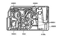
4080D 不溶性成分分離部
4080E、3000G 多段送液部
4080H 肉抜き
2100、3100、4100 主面
2100a、3100a、4100a 第1主面
2100b、3100b、4100b 第2主面
5001 第1の混合液保持槽
5002 第2の混合液保持槽
1011
2030 Insoluble
U-3 Third stage liquid feeding unit (lower liquid feeding unit)
U-4 4th stage liquid feeding unit (lower liquid feeding unit)
3010-3 Second liquid storage tank (reagent storage tank) of the first stage liquid supply unit
3020-3 Second storage tank (reagent storage tank) of second stage liquid-feeding unit
3030-3 Second liquid storage tank (reagent liquid storage tank) of third stage liquid supply unit
3040-3 Second storage tank (reagent storage tank) of the fourth-stage liquid feeding unit
3011 Air flow path 3011-1 First storage tank vent hole 3011-2 Air flow path 3011-3 leading to the second holding tank of the first stage liquid supply unit Air flow path 3011-4 leading to the second holding tank Air flow path 3011-5 leading to the second holding tank of the third stage liquid feeding unit To the first holding tank of the first stage liquid feeding unit Vent hole 3011-6 communicating Vent hole 3011-7 communicating with the first holding tank of the second stage liquid feeding unit Vent hole 3011-8 leading to the first holding tank of the third stage liquid feeding
3000B-1 Channel B of the first-stage liquid feeding unit
3000B-2 Flow path B of lower liquid supply unit (second liquid supply unit)
3000B-3 Channel B of the third-stage liquid feeding unit
3000B-4 Flow path B of the fourth-stage liquid feeding unit
3000C-1 Flow path C connecting the first and second stage liquid feeding units
3000C-2 Flow path C connecting the second and third stage liquid feeding units
3000C-3 Flow path C connecting the third and fourth liquid supply units
3000D Channel D
3000D-1 First half portion of
3000D-3
3000E-1 Channel E of the first-stage liquid-feeding unit
3000E-2 Channel E of the second-stage liquid-feeding unit
3000E-3 Flow path E of the third-stage liquid feeding unit
3000E-4 Flow path E of the fourth-stage liquid feeding unit
3000L1 Liquid 3000P1 A plane 3000P2 including the liquid level of the liquid in the first liquid storage tank when the chip is rotated at the first rotation speed. The first when the chip is rotated at the first rotation speed. Plane 3000P3 including the liquid level of the liquid in the holding tank plane 3000P4 including the liquid level of the liquid in the first holding tank when the chip is rotated at the second rotation speed or when the rotation is stopped. When the chip is rotated at a rotational speed of 2 or when the rotation is stopped, the plane 3000P5 including the liquid level of the liquid in the second holding tank is rotated. The plane 3000P6 including the liquid level of the liquid in the holding tank The plane 3000P7, 3000P8, 3000P9 including the liquid level of the liquid in the second holding tank when the rotation is stopped. The chip is rotated at the first rotation speed. Plane 3000Q1 including the liquid level of the liquid in the second liquid storage tank when connected to the first storage tank 3000Q2 of the flow path A connection section 3000Q3 of the flow B to the first liquid storage tank Connection part 3000Q4, 3000Q5, 3000Q6 with the first storage tank in the path C Connection part 3000Q7, 3000Q8, 3000Q9 with the second storage tank in the flow path E Connection part 3000S1 with the second holding tank in the flow path E Extension line 3000S2 of flow path B Extension line 3000S3 of flow path C Extension line 3000s1 of flow path A Angle 3000s2 formed by the extension line of flow path B and the rotation axis Angle 3000s3 formed by the extension line of flow path C and the rotation axis Angles 4002, 4005, 4008, 4011, 4014, 4017 formed by the extension line of the path A and the rotation axis Opening 4003 of the reagent reservoir unit Opening 400 of the reagent introduction path of the chip body , 4009, 4012, 4015 Opening 4020 of chip body flow path E Waste liquid tank 4021 Discharge path 4022 Prefilter part 4023A, 4023B Protruding part 4024A, 4024B Space 4025A, 4025B Recess 4030, 4040, 4050, 4060, 4070 Chip 4030A, 4040A, 4050A, 3000F, 4070F Reagent reservoir unit 4030B, 4040B, 4050B, 4070B, 4080B Chip body 4030C, 4040C, 4050C, 4070C, 4080C Reaction chamber unit 4080D Insoluble component separation unit 4080E, 3000G Multistage liquid feeding unit 4080H Meat removal 2100, 3100, 4100 Main surface 2100a, 3100a, 4100a First main surface 2100b, 3100b, 4100b Second main surface 50 1 first mixture holding tank 5002 second mixed liquid holding tank
以下、本発明の分析チップについて、用途、分析チップの材料、製法などを説明した後、分析チップの構成要素である反応室ユニット、不溶性成分分離部、多段送液部、および必要に応じて設けられる試薬リザーバユニットならびに廃液槽をそれぞれ説明し、その上で、分析チップの全体構造、および分析チップを使用した免疫分析方法について説明する。 Hereinafter, for the analysis chip of the present invention, the application, the material of the analysis chip, the production method, etc. will be described, and then a reaction chamber unit, an insoluble component separation unit, a multistage liquid feeding unit, and components provided as necessary will be provided. The reagent reservoir unit and the waste tank to be used will be described, respectively, and then the whole structure of the analysis chip and the immunoassay method using the analysis chip will be described.
なお、各図は、発明が理解できる程度に、構成要素の形状、大きさおよび配置が概略的に示されているに過ぎない。本発明は以下の記述によって限定されるものではなく、各構成要素は本発明の要旨を逸脱しない範囲において適宜変更可能である。また、図中、パターンを付した箇所は、液体(懸濁液、分離液、洗浄液等の試薬など)、不溶性成分等自体を、またはこれらが存在していることを意味している。以下の説明に用いる各図において、同様の構成要素については同一の符号を付して示し、重複する説明を省略する場合がある。 In addition, each figure has shown only the shape of the component, the magnitude | size, and arrangement | positioning to such an extent that an invention can be understood. The present invention is not limited to the following description, and each component can be appropriately changed without departing from the gist of the present invention. Further, in the drawing, a place with a pattern means that a liquid (a reagent such as a suspension, a separation liquid, a washing liquid, etc.), an insoluble component or the like itself, or the presence of these. In each drawing used for the following description, the same components are denoted by the same reference numerals, and redundant description may be omitted.
以下の説明において、上方、下方(重力方向)、外周側、内周側などと称される配置関係の説明は、分析チップ使用時、すなわち分析チップが回転装置に設置された状態を基準として定義される。後述するように、回転時に分析チップを傾ける場合には、傾けた状態を基準とする。また、分析チップの主面を水平として回転させる場合には、この状態を基準として説明する場合がある。 In the following description, the description of the arrangement relationship referred to as “upper”, “lower” (gravity direction), outer peripheral side, inner peripheral side, etc. is defined with reference to the state in which the analysis chip is used, that is, the analysis chip is installed in the rotating device. Is done. As will be described later, when the analysis chip is tilted during rotation, the tilted state is used as a reference. Further, when the main surface of the analysis chip is rotated horizontally, it may be described based on this state.
以下の説明において、「外周側」とは回転軸を基準として、遠心力の働く方向、すなわち回転軸から遠ざかる方向を意味する。「内周側」とは外周側とは反対方向、すなわち回転軸に向かう方向を意味する。 In the following description, the “outer peripheral side” means a direction in which centrifugal force acts, that is, a direction away from the rotation axis with respect to the rotation axis. “Inner circumference side” means a direction opposite to the outer circumference side, that is, a direction toward the rotation axis.
また、「重力方向」とは、分析チップの回転時に重力が働く方向として定義され、下方とも表現される。ここで重力方向とは、必ずしも鉛直方向に限られず、鉛直方向の成分を含むベクトルが示す方向(略鉛直方向)も含まれる。また、重力方向は、重力の作用により分析チップ内の液体が流れる方向を意味するとも表現できる。なお、本発明において上方とは、重力方向とは反対の方向として定義される。以下の説明において上方、下方と表現する場合には、何らかの基準に対する相対的位置をいう場合がある。 The “gravity direction” is defined as a direction in which gravity works when the analysis chip rotates, and is also expressed as a downward direction. Here, the gravitational direction is not necessarily limited to the vertical direction, and includes a direction (substantially vertical direction) indicated by a vector including a component in the vertical direction. The direction of gravity can also be expressed as the direction in which the liquid in the analysis chip flows due to the action of gravity. In the present invention, the upward direction is defined as a direction opposite to the direction of gravity. In the following description, the terms “upper” and “lower” may refer to a relative position with respect to some reference.
さらに、以下の説明において、「送液」とは、液体(懸濁液、分離液および洗浄液)を分析チップ内部の複数の槽間で、例えば流路により流動的に移動させることを意味する。 Furthermore, in the following description, “liquid feeding” means that the liquid (suspension, separation liquid, and washing liquid) is fluidly moved between a plurality of tanks inside the analysis chip, for example, by a flow path.
以下の説明において、「主面」とは、分析チップを透過的に見た時に、分析チップのソリッドな厚み内に空間として設けられている槽および流路を観察できる側の面を意味する。例えば形状が多面体の、好ましくは立方体又は直方体の薄板状の、分析チップの場合、互いに対向する2つの面が主面となりうる。なお、以下の説明において分析チップが互いに対向する2つの主面を有する場合、便宜上、それぞれを第1主面、第2主面と称するものとする。 In the following description, the “main surface” means a surface on the side where a tank and a channel provided as a space within the solid thickness of the analysis chip can be observed when the analysis chip is viewed transparently. For example, in the case of an analysis chip having a polyhedron shape, preferably a cubic or rectangular parallelepiped thin plate shape, two surfaces facing each other can be main surfaces. In the following description, when the analysis chip has two main surfaces facing each other, for the sake of convenience, they are referred to as a first main surface and a second main surface, respectively.
第1主面および第2主面から透過的に観察され得る流路および槽は、通常は表裏の関係であり対称をなすが、後述のように、前記不溶性成分分離部および前記多段送液部の少なくとも一部が、互いに対向する2つの主面寄りに互いに離間して設けられている場合には、まったく異なる流路および槽が観察される場合がある。例えば、図37の分析チップにおいて、第1主面4100aから見た流路は、第1主面4100aと対向する(第1主面4100aを表側の面とした場合に裏側の面に該当する)第2主面4100bとを、主面として有しており、この場合は第1主面4100aから観察される流路および槽が、第2主面4100bから観察するといわば裏側から観察することになる。一方、図51−1および図51−2の分析チップにおいて、第1主面4100a側から観察される槽や流路の配置と、第2主面4100bから観察される槽や流路の配置はまったく異なる。
The flow paths and tanks that can be observed transparently from the first main surface and the second main surface are usually in a front-back relationship and symmetrical, but as described later, the insoluble component separation unit and the multistage liquid feeding unit In the case where at least a part of is provided apart from each other near the two main surfaces facing each other, completely different flow paths and tanks may be observed. For example, in the analysis chip of FIG. 37, the flow path viewed from the first
なお、各図において、分析チップの厚み内の槽および流路は、原則として輪郭が実線で示されている。また、各図において、分析チップの一部を示す場合には、輪郭が一点鎖線で示されている。さらに、各図において、分析チップの第1主面寄りの槽または流路を第2主面側から見て(観察して)表す場合、或いは第2主面寄りの槽または流路を第1主面側から見て表す場合には、観察された主面とは対向する主面寄り(厚みの奥側)に配置される槽または流路の輪郭が破線で示される。 In addition, in each figure, the outline of the tank and the flow path within the thickness of the analysis chip is indicated by a solid line in principle. Moreover, in each figure, when showing a part of analysis chip, the outline is shown with the dashed-dotted line. Furthermore, in each figure, when the tank or flow path near the first main surface of the analysis chip is shown (observed) when viewed from the second main surface side, or the tank or flow path near the second main surface is shown in the first view. When viewed from the main surface side, the outline of the tank or the channel disposed near the main surface (the back side of the thickness) opposite to the observed main surface is indicated by a broken line.
1.チップについて
〔免疫分析〕
本発明の分析チップは、免疫分析に用いる分析チップである。本発明において免疫分析とは、検体中の被検物質を、抗原抗体反応を利用して分析する手法を意味し、その代表的なものとしてELISA(Enzyme−Linked Immunosorbent Assay 固相酵素免疫検定法)、RIA(Radioimmunoassay 放射線免疫検定法)、FIA(Fluorescenceimmunoassay 蛍光免疫検定法)、FLISA(Fluorescence−Linked Immunosorbent Assay 固相蛍光免疫検定法)を挙げることができる。
1. About the chip [immunoassay]
The analysis chip of the present invention is an analysis chip used for immunoassay. In the present invention, immunoassay means a technique for analyzing a test substance in a sample using an antigen-antibody reaction, and a representative example thereof is ELISA (Enzyme-Linked Immunosorbent Assay solid phase enzyme immunoassay). And RIA (Radioimmunoassay radioimmunoassay), FIA (Fluorescence immunoassay fluorescent immunoassay), and FLISA (Fluorescence-Linked Immunosorbent solid phase immunofluorescence assay).
分析の方法としては
1)標識した抗体により目的とする物質を直接認識し検出する直接法、
2)目的とする物質を抗体により認識し、目的物質と結合した抗体を、標識した抗体により認識し検出する間接法、
3)競合法、
4)目的とする物質を固相化した抗体(1次抗体)により捕捉し、さらに別の標識した抗体(2次抗体)により検出する二抗体サンドイッチ法、
5)目的とする物質を固相化した抗体により捕捉し、さらに別の抗体により目的とする物質を認識し、目的とする物質を、認識した抗体を標識した抗体により検出する三抗体サンドイッチ法、
等が挙げられる。
また、ABC法などの、アビジン、ストレプトアビジン等を用いて、被検物質を検出する手法を利用してもよい。
The analysis method is as follows: 1) a direct method for directly recognizing and detecting the target substance with the labeled antibody;
2) An indirect method of recognizing a target substance with an antibody and recognizing and detecting an antibody bound to the target substance with a labeled antibody,
3) Competition method,
4) A two-antibody sandwich method in which a target substance is captured by an immobilized antibody (primary antibody) and further detected by another labeled antibody (secondary antibody),
5) A three-antibody sandwich method in which the target substance is captured by an immobilized antibody, the target substance is recognized by another antibody, and the target substance is detected by an antibody labeled with the recognized antibody.
Etc.
Further, a method of detecting a test substance using avidin, streptavidin or the like, such as ABC method, may be used.
免疫分析における被検物質は、タンパク質、糖、脂質、核酸、糖タンパク質、糖脂質、細胞など、抗原や抗体と特異的に結合する物質であればいずれであってもよい。例えばサイトカイン、ケモカイン、インターロイキン、アレルゲン、DNA、RNA、抗体、脂質、酵素、その他化学物質等を挙げることができる。特に、IL−6、IL−8、TNFが好ましい。被検物質の由来生物は問わない。被検物質は1種類であってもよく、また2種類以上であってもよい。 The test substance in the immunoassay may be any substance that specifically binds to an antigen or antibody, such as a protein, sugar, lipid, nucleic acid, glycoprotein, glycolipid, or cell. Examples include cytokines, chemokines, interleukins, allergens, DNA, RNA, antibodies, lipids, enzymes, and other chemical substances. In particular, IL-6, IL-8, and TNF are preferable. The organism from which the test substance is derived does not matter. The test substance may be one type or two or more types.
また、免疫分析の目的は特に限定されず、検体中の被検物質の有無の検出、被検物質の定量など特に限定されない。本発明における免疫分析は、臨床検査、食品検査、環境検査などにおける分析に用いることができる。 The purpose of immunoassay is not particularly limited, and there is no particular limitation such as detection of the presence or absence of a test substance in a sample, quantification of a test substance. The immunoassay in the present invention can be used for analysis in clinical tests, food tests, environmental tests and the like.
〔チップの回転〕
本発明の分析チップでは、分析チップを回転させ、回転の繰り返しにより検体及び複数の試薬が順次反応室ユニットに送液され上記免疫分析が行われる。すなわち、分析チップを、分析チップの主面が回転軸を含む平面に沿う向きとなるように、回転装置に装着し、回転速度を変化させることにより、検体及び複数の試薬が順次反応室ユニットに送液され上記免疫分析が行われる。本発明の分析チップによれば、回転による遠心力と、回転停止による自由落下を繰り返すのみで、検体および複数の試薬を順次反応室ユニットに送液することができる。すなわち、本発明の分析チップは、回転軸を含む平面に沿って回転装置に装着し、回転速度を変化させることにより、各槽間における不溶性成分の分離、検体や試薬の送液、免疫反応を実現するものである。更に言い換えれば、第1の回転速度による回転、および第1の回転速度より低速の第2の回転速度による回転または回転停止を順次行うことにより、上記分離、送液、反応を一つの分析チップで実現するものである。前述したように本発明の分析チップによる送液等は、遠心力および重力を利用して行うものであるので、分析チップの回転速度の変化に代えて、回転軌道半径を変化させて免疫分析を行ってもよい。
[Rotating tip]
In the analysis chip of the present invention, the analysis chip is rotated, and the sample and a plurality of reagents are sequentially sent to the reaction chamber unit by repeating the rotation, and the immunoassay is performed. That is, by attaching the analysis chip to the rotation device so that the main surface of the analysis chip is oriented along the plane including the rotation axis and changing the rotation speed, the specimen and the plurality of reagents are sequentially transferred to the reaction chamber unit. The solution is fed and the above immunoassay is performed. According to the analysis chip of the present invention, the sample and the plurality of reagents can be sequentially fed to the reaction chamber unit only by repeating the centrifugal force due to the rotation and the free fall due to the rotation stop. That is, the analysis chip of the present invention is mounted on a rotating device along a plane including a rotation axis, and by changing the rotation speed, separation of insoluble components between each tank, feeding of specimens and reagents, and immune reaction are performed. It is realized. In other words, the separation, liquid feeding, and reaction can be performed on a single analysis chip by sequentially performing rotation at the first rotation speed and rotation or rotation stop at the second rotation speed lower than the first rotation speed. It is realized. As described above, liquid feeding using the analysis chip of the present invention is performed by utilizing centrifugal force and gravity. Therefore, instead of changing the rotation speed of the analysis chip, the immunological analysis is performed by changing the rotational orbit radius. You may go.
本発明において回転とは、ある中心軸(回転軸)を基準にその周囲を回ることを意味し、自転に対する公転と呼ばれることがある。回転の軌道は略円形であればよく、軌道半径について特に限定はない。回転時の分析チップの方向は特に問わないが、通常は、分析チップ主面を回転周方向に向けた回転であることが好ましい。すなわち、分析チップの主面(透過的に見たときに、各槽および流路を観察できる側の面)を回転軸を含む平面に沿って回転装置に装着し、回転軌道の周方向に向けて回転させることが好ましい。 In the present invention, rotation means turning around a certain center axis (rotation axis), and is sometimes referred to as revolution with respect to rotation. The rotation trajectory may be substantially circular, and the trajectory radius is not particularly limited. The direction of the analysis chip during rotation is not particularly limited, but it is usually preferable to rotate the analysis chip main surface in the rotation circumferential direction. That is, the main surface of the analysis chip (the surface on the side where each tank and flow path can be observed when viewed transparently) is attached to the rotating device along the plane including the rotation axis, and is directed in the circumferential direction of the rotating track. It is preferable to rotate them.
本発明における回転軸は、鉛直方向に延在する軸であることが好ましい。回転軸が鉛直方向に対して角度を有する場合、すなわち回転軸が鉛直方向に対して傾いている場合、幾つかの問題が生じうる。まず、1000rpmを超える高い回転速度での回転時には、回転軸やモーターへの負荷が大きくなることから、分析チップを回転させるための回転装置(例えば、遠心機などのローター)においてそれに耐えうるモーターを用いる必要があり、装置価格が高くなる。また、複数の分析チップをローターに同時に装着して測定する場合、回転停止時に、分析チップの向きに対する重力の方向が、複数の分析チップ間で異なるため、ローターに装着された複数の分析チップ間で重力により送液される方向が異なってしまう。そのため、複数の分析チップを同時にローターに装着し、測定することができない。この理由により、多検体の同時測定や、多項目の同時測定を行うことは不可能である。一方、回転軸が鉛直方向に延在する場合、複数の分析チップを回転軸の周りに、同一水平面上に位置するように設置することができることから、回転時に働く遠心力や、回転停止時に働く重力を、複数の分析チップ間で均一に働かせることができる。そのため、多検体の同時測定や、多項目の同時測定を行うことが可能である。 The rotation axis in the present invention is preferably an axis extending in the vertical direction. When the rotation axis has an angle with respect to the vertical direction, that is, when the rotation axis is inclined with respect to the vertical direction, several problems may occur. First, when rotating at a high rotational speed exceeding 1000 rpm, the load on the rotating shaft and the motor becomes large. Therefore, a rotating device for rotating the analysis chip (for example, a rotor such as a centrifuge) must be equipped with a motor that can withstand it. It is necessary to use it, and the apparatus price becomes high. Also, when measuring with multiple analysis chips mounted on the rotor at the same time, the direction of gravity with respect to the direction of the analysis chip differs between the multiple analysis chips when rotation stops, so between the multiple analysis chips mounted on the rotor The direction of liquid feeding will be different due to gravity. Therefore, a plurality of analysis chips cannot be simultaneously mounted on the rotor and measured. For this reason, it is impossible to perform simultaneous measurement of multiple samples or simultaneous measurement of multiple items. On the other hand, when the rotation axis extends in the vertical direction, a plurality of analysis chips can be installed around the rotation axis so as to be located on the same horizontal plane. Gravity can be applied uniformly between multiple analysis chips. Therefore, simultaneous measurement of multiple samples and simultaneous measurement of multiple items can be performed.
更に、一つの分析チップで測定を行う場合でも、遠心力が小さい条件、すなわち回転停止直前もしくは回転開始直後には、遠心力と重力の合力が内部の流体に働くため、望まぬ流体の移動を引き起こす可能性がある。一方、回転軸が鉛直方向に延在する場合、回転停止直前もしくは回転開始直後の重力の影響がほとんど無いため、安定な送液、測定が可能である。 Furthermore, even when measurement is performed with a single analysis chip, undesired movement of the fluid is caused because the resultant force of the centrifugal force and gravity acts on the internal fluid under conditions where the centrifugal force is small, that is, immediately before the rotation is stopped or immediately after the rotation is started. May cause. On the other hand, when the rotation axis extends in the vertical direction, there is almost no influence of gravity immediately before stopping rotation or immediately after starting rotation, so that stable liquid feeding and measurement are possible.
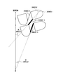
分析チップの主面を回転軌道の周方向に向けて回転させる場合には、例えば図42−1に示される分析チップのように回転軸に対し主面を平行に立てて回転させることができる。すなわち、分析チップの回転側かつ上側の角隅部を、回転軸側かつ下側の角隅部を支点として回転軸側に傾けて回転させることもできる。分析チップの傾きは、主面の回転軸側の辺縁が、回転軸に対し10°から80°、好ましくは20°から50°をなすような位置とすることができる。 When the main surface of the analysis chip is rotated in the circumferential direction of the rotation trajectory, the main surface can be rotated in parallel with the rotation axis like the analysis chip shown in FIG. That is, the rotation corner and the upper corner of the analysis chip can be tilted and rotated toward the rotation axis with the rotation corner and the lower corner as a fulcrum. The inclination of the analysis chip can be set such that the edge on the rotation axis side of the main surface forms 10 ° to 80 °, preferably 20 ° to 50 ° with respect to the rotation axis.
一方、図50−1、図50−2、図50−3および図50−4に示される分析チップ、並びに図51−1及び図51−2に示される分析チップの場合、複数の槽及び流路が略水平方向に並列的に配置されている。これらの分析チップは、回転装置装着時に傾ける必要はなく、主面の回転軸側の辺縁は、回転軸に対して平行とされ得る。 On the other hand, in the case of the analysis chip shown in FIGS. 50-1, 50-2, 50-3 and 50-4, and the analysis chip shown in FIGS. The roads are arranged in parallel in a substantially horizontal direction. These analysis chips do not need to be inclined when the rotating device is mounted, and the edge on the rotating shaft side of the main surface can be parallel to the rotating shaft.
本発明における回転停止とは、完全に回転が停止し、分析チップに加わる遠心力が0Gとなる状態を意味する。しかしながら、ごく低速での回転であっても、重力が送液の動力源となる程度に低速であれば、回転停止(状態)と定義される。具体的には、分析チップに加わる遠心力が3G以下程度であれば、重力方向に延伸する流路や接続部を介して、重力の作用により重力方向の送液を行うことが可能である。したがって、この場合は回転停止(状態)である。 The rotation stop in the present invention means a state in which the rotation is completely stopped and the centrifugal force applied to the analysis chip is 0G. However, even if the rotation is at a very low speed, it is defined as a rotation stop (state) if the gravity is low enough to be a power source for liquid feeding. Specifically, if the centrifugal force applied to the analysis chip is about 3 G or less, liquid feeding in the gravitational direction can be performed by the action of gravity through a flow path and a connecting portion extending in the gravitational direction. Therefore, in this case, the rotation is stopped (state).
本発明における上方、下方(重力方向)、外周側、内周側などの位置の特定は、分析チップ使用時に主面を正面から見た場合の位置として定義される。上述したように分析チップの回転時に分析チップを傾斜させる場合には、傾斜させた状態で分析チップ主面を正面から見た場合の位置である。 In the present invention, the specification of the positions such as the upper side, the lower side (gravity direction), the outer peripheral side, and the inner peripheral side is defined as the position when the main surface is viewed from the front when using the analysis chip. As described above, when the analysis chip is tilted when the analysis chip is rotated, it is the position when the analysis chip main surface is viewed from the front in the tilted state.
本発明における重力方向とは、分析チップの回転時に重力が働く方向として定義され、下方とも表現される。ここで重力方向とは、必ずしも完全な鉛直方向である必要はなく、鉛直方向のベクトルを持つ方向(略鉛直方向)でありさえすればよい。重力方向は、重力の作用により液体が流れる方向を意味するとも表現できる。一方、本発明において上方とは、重力方向と反対の方向として定義される。なお、本発明において上方、下方と表現する場合には、何らかの基準に対する相対的位置をいう場合がある。 The gravity direction in the present invention is defined as a direction in which gravity works when the analysis chip rotates, and is also expressed as a downward direction. Here, the gravitational direction is not necessarily a complete vertical direction, and may be a direction having a vertical vector (substantially vertical direction). The direction of gravity can also be expressed as the direction in which liquid flows by the action of gravity. On the other hand, upward in the present invention is defined as a direction opposite to the direction of gravity. In the present invention, the terms “upper” and “lower” may refer to a relative position with respect to some reference.
〔チップの形状〕
本発明の分析チップの形状は、通常は、立方体または直方体の薄板状である。本発明の分析チップのサイズは、回転装置(遠心機など)に装着可能な大きさであればよい。測定者への感染リスクを低減するために、本発明の分析チップは使い捨てとすることが好ましい。
[Chip shape]
The shape of the analysis chip of the present invention is usually a cube or a rectangular parallelepiped thin plate. The size of the analysis chip of the present invention may be any size that can be attached to a rotating device (such as a centrifuge). In order to reduce the risk of infection to the measurer, the analysis chip of the present invention is preferably disposable.
本発明の分析チップは、ローターに装着されて用いられることが好ましい。更に好ましくは、アングルローターが用いられる。このとき、アングルローターに装着された状態の分析チップの傾きを考慮して、流路の延伸方向(延伸角度)、槽の形状を制御することが容易となる。ローターとしては、重力を利用した送液が可能な程度の厚みを持つ分析チップを回転できるものであればよく、例えば数センチメートル程度の厚みを持つ円柱状のローターを用いることもできる。ローターは、一度に複数の検体もしくは測定項目について測定できることから、複数の分析チップが装着可能であるローターが好ましい。 The analysis chip of the present invention is preferably used by being attached to a rotor. More preferably, an angle rotor is used. At this time, in consideration of the inclination of the analysis chip attached to the angle rotor, it becomes easy to control the extending direction (stretching angle) of the flow path and the shape of the tank. As the rotor, any rotor capable of rotating an analysis chip having a thickness capable of feeding liquid using gravity may be used. For example, a cylindrical rotor having a thickness of about several centimeters may be used. Since the rotor can measure a plurality of samples or measurement items at a time, a rotor to which a plurality of analysis chips can be attached is preferable.
〔懸濁液、検体、試薬〕
本発明における懸濁液とは、1種または2種類以上の固体、液体が混合された液体を意味する。中でも、生体成分の混合液(生体試料)が好ましい。例えば、血液、尿、髄液、唾液、痰、細胞懸濁液などをはじめとする生体から採取される液体といった生体試料や細胞培養液、細胞懸濁液、細胞破砕液、核酸溶液、ウィルス懸濁液、食品抽出液、土壌抽出液もしくは水等の環境抽出液等を挙げることができる。本発明の分析チップに適用される懸濁液としては、これらのうち、血液、尿が好ましい。
[Suspension, specimen, reagent]
The suspension in the present invention means a liquid in which one or more kinds of solids and liquids are mixed. Among these, a mixture of biological components (biological sample) is preferable. For example, biological samples such as blood, urine, cerebrospinal fluid, saliva, sputum, cell suspension, and other biological samples collected from living organisms, cell culture solutions, cell suspensions, cell disruptions, nucleic acid solutions, virus suspensions. Examples include turbid liquids, food extracts, soil extracts, or environmental extracts such as water. Of these, blood and urine are preferable as the suspension applied to the analysis chip of the present invention.
本発明における不溶性成分(不溶成分)とは、懸濁液に遠心力および重力をかけることにより溶質(液状成分:分離液)から分離される成分を意味する。不溶性成分は通常比重が分離液よりも大きい。 The insoluble component (insoluble component) in the present invention means a component that is separated from a solute (liquid component: separated liquid) by applying centrifugal force and gravity to the suspension. Insoluble components usually have a specific gravity greater than that of the separation liquid.
不溶性成分としては例えば、血球などの細胞、血餅、微生物、変性したタンパク質などの澱状の固形物や凝集物、尿酸などの結晶などが挙げられる。 Examples of the insoluble component include cells such as blood cells, blood clots, microorganisms, starch-like solids and aggregates such as denatured proteins, crystals such as uric acid, and the like.
懸濁液が例えば血液であるとき、分離または除去される不溶性成分の具体例としては、血球などの細胞成分や血餅が挙げられ、分取される分離液として、血清や血漿が挙げられる。 Specific examples of insoluble components to be separated or removed when the suspension is blood, for example, include cell components such as blood cells and blood clots, and separation liquids to be collected include serum and plasma.
懸濁液が例えば尿であるとき、分離または除去される不溶性成分の具体例として、細胞成分や尿酸が挙げられ、分取される分離液として、尿上清が挙げられる。 When the suspension is, for example, urine, specific examples of the insoluble component to be separated or removed include cell components and uric acid, and the separated liquid to be separated includes urine supernatant.
試薬とは、検体を検出するための試薬を意味し、具体的には、ブロッキング溶液、希釈液、変性剤、標識抗体、標識抗原、未標識抗体、未標識抗原、標識物質、発光基質、蛍光基質、発色基質、過酸化水素水、洗浄液、タンパク質変性剤、細胞溶解液、酵素溶液、標識核酸、未標識核酸、プライマー、プローブ、アビジン、ストレプトアビジン、緩衝液、pH調整溶液、ハイブリダイゼーション溶液、酵素反応停止液等を挙げることができる。 Reagent means a reagent for detecting a specimen, specifically, blocking solution, diluent, denaturant, labeled antibody, labeled antigen, unlabeled antibody, unlabeled antigen, labeled substance, luminescent substrate, fluorescence Substrate, chromogenic substrate, hydrogen peroxide solution, washing solution, protein denaturant, cell lysate, enzyme solution, labeled nucleic acid, unlabeled nucleic acid, primer, probe, avidin, streptavidin, buffer solution, pH adjustment solution, hybridization solution, An enzyme reaction stop solution can be used.
〔チップの材料〕
本発明の分析チップの材料は特に限定されず、例えば、樹脂、ガラスなどが挙げられる。特に反応室ユニットについては、反応室を外部から観察することが容易になる観点から、少なくとも反応室の一部が透明であることが好ましい。反応室の少なくとも一部が透明とすることにより、濃縮あるいは捕捉された被検物質を光学的に容易に検出することができると共に、送液状況を外部から容易に確認することができる。したがって、反応室の一部に透明材料を用いることが好ましく、特に全体を透明材料から形成することが好ましい。また、反応室の透明材料からなる部分の表面は、平面であってもよいし、レンズ状(凹面)であってもよい。
[Chip material]
The material of the analysis chip of the present invention is not particularly limited, and examples thereof include resin and glass. In particular, for the reaction chamber unit, it is preferable that at least a part of the reaction chamber is transparent from the viewpoint of facilitating observation of the reaction chamber from the outside. By making at least a part of the reaction chamber transparent, it is possible to easily detect optically the concentrated or captured test substance and to easily check the liquid feeding condition from the outside. Therefore, it is preferable to use a transparent material for a part of the reaction chamber, and it is particularly preferable to form the whole from a transparent material. Further, the surface of the reaction chamber made of a transparent material may be a flat surface or a lens shape (concave surface).
さらに、液体の種類にかかわらず安定に送液するための材料として、耐薬品性、耐水性に優れ、化学的に安定な材料が好ましい。 Further, as a material for stably feeding regardless of the type of liquid, a material which is excellent in chemical resistance and water resistance and chemically stable is preferable.
本発明における親水的な表面とは、接触角が90度以下の表面を意味する。接触角の測定は、20℃、50%RHの条件下で、水に対する接触角を接触角計を用いて測定することで調べることができる。 The hydrophilic surface in the present invention means a surface having a contact angle of 90 degrees or less. The contact angle can be measured by measuring the contact angle with respect to water using a contact angle meter under the conditions of 20 ° C. and 50% RH.
本発明における疎水的な表面とは、接触角が90度より大きい表面を意味し、撥水性とも表現される。疎水的な表面の形成には、フルオロカーボン系樹脂、シリコーン系樹脂などの撥水剤を表面に塗布すればよい。 The hydrophobic surface in the present invention means a surface having a contact angle larger than 90 degrees and is also expressed as water repellency. In order to form a hydrophobic surface, a water repellent such as a fluorocarbon resin or a silicone resin may be applied to the surface.
反応室ユニットは、少なくともその一部が、光透過率(光線透過率)80%以上、好ましくは90%以上、更に好ましくは93%以上の特性を持つ樹脂から形成されていてもよい。これにより、反応室内で生じる蛍光、発光を減衰させることなく検出可能であることから、被検物質を感度良く検出できるので好ましい。光透過率の測定は、光透過率計、分光光度計により行うことができる。また、JIS規格JIS K7105に従って測定することもできる。 At least a part of the reaction chamber unit may be formed of a resin having a light transmittance (light transmittance) of 80% or more, preferably 90% or more, more preferably 93% or more. Thereby, since it is possible to detect fluorescence and luminescence generated in the reaction chamber without attenuating, it is preferable because the test substance can be detected with high sensitivity. The light transmittance can be measured with a light transmittance meter or a spectrophotometer. It can also be measured according to JIS standard JIS K7105.
本発明の分析チップにおいて、反応室ユニットと、必要に応じて設けてもよい試薬リザーバユニットとは、チップ本体から着脱可能にすることによりチップ本体を構成する樹脂とは異なる樹脂により形成することができる。これにより、光学特性や吸水率など分析チップの機能に合った性質の樹脂を選択することができるので好ましい。反応室ユニットは、前述のように光透過性が高い樹脂により形成されることが望ましい。一方、試薬リザーバユニットは、液体試薬の長期安定保存を達成するため、吸水率が低い樹脂により形成されることが望ましい。さらに、光による劣化を避けるため、光透過率が低い樹脂を材料とすることが望ましい。また、一般に光透過率が高い樹脂は高価であるため、容積の小さい反応室ユニットの材料には高価で光透過性に優れる樹脂を用い、それ以外の部位、ユニットの材料には安価な樹脂を用いるのがよい。 In the analysis chip of the present invention, the reaction chamber unit and the reagent reservoir unit which may be provided as necessary may be formed of a resin different from the resin constituting the chip body by being detachable from the chip body. it can. This is preferable because a resin having properties suitable for the function of the analysis chip such as optical characteristics and water absorption can be selected. As described above, the reaction chamber unit is preferably formed of a resin having high light transmittance. On the other hand, the reagent reservoir unit is desirably formed of a resin having a low water absorption rate in order to achieve long-term stable storage of the liquid reagent. Furthermore, in order to avoid deterioration due to light, it is desirable to use a resin having a low light transmittance. In general, a resin having a high light transmittance is expensive. Therefore, an inexpensive resin having excellent light transmittance is used as a material for a reaction chamber unit having a small volume, and an inexpensive resin is used as a material for other parts and units. It is good to use.
このように、一つの分析チップの各部位、各ユニットに求められる機能に適した樹脂を材料としてそれぞれ選択すれば、分析チップ全体としてのコストを低く抑えることができるので好ましい。 As described above, it is preferable to select a resin suitable for the function required for each part and each unit of one analysis chip as a material because the cost of the entire analysis chip can be suppressed.
また、試薬リザーバユニットは、少なくともその一部が、吸水率0.1%以下、中でも0.03%以下の特性を持つ樹脂から形成されていてもよい。これにより、試薬の濃度が変化することなく、試薬を長期間保存できるので好ましい。なお、吸水率の上限は通常0.2%である。吸水率の測定は、重量測定により行うことができる。JIS規格JIS K7209に従って測定することもできる。 Further, at least a part of the reagent reservoir unit may be formed of a resin having a water absorption rate of 0.1% or less, particularly 0.03% or less. This is preferable because the reagent can be stored for a long period of time without changing the concentration of the reagent. The upper limit of water absorption is usually 0.2%. The water absorption rate can be measured by weight measurement. It can also be measured according to JIS standard JIS K7209.
さらに、試薬リザーバユニットは、少なくともその一部が、光透過率(光線透過率)10%以下、好ましくは1%以下の特性を持つ樹脂から形成されていてもよい。これにより、光分解性を持つ試薬を保存できるので好ましい。光透過率の測定は、分光光度計により行うことができる。光透過率は、例えばJIS規格JIS K7105に従って測定することもできる。光透過率を低下させる目的で、色素やカーボンなどを含有する樹脂が用いられることもある。 Further, at least a part of the reagent reservoir unit may be formed of a resin having a light transmittance (light transmittance) of 10% or less, preferably 1% or less. This is preferable because a reagent having photodegradability can be stored. The light transmittance can be measured by a spectrophotometer. The light transmittance can also be measured according to, for example, JIS standard JIS K7105. For the purpose of reducing the light transmittance, a resin containing a pigment or carbon may be used.
分析チップに用いられる材料(素材)としては、各種有機材料、無機材料を挙げることができ、例えば、ポリメチルメタクリル酸メチル(PMMA)などのアクリル樹脂、ポリカーボネート、ポリプロピレン、ポリエチレン、ポリメチルペンテン、ポリスチレン、ポリテトラフルオロエチレン、ABS樹脂、ポリジメチルシロキサン、シリコン等の樹脂、それらの高分子化合物を含む共重合体あるいは複合体;石英ガラス、パイレックス(登録商標)ガラス、ソーダガラス、ホウ酸ガラス、ケイ酸ガラス、ホウケイ酸ガラス等のガラス類およびその複合体;表面を絶縁材料で被覆した金属及びその複合体、セラミックス及びその複合体等が好ましく用いられる。樹脂はガラスなどと比較し、量産性に優れ、コスト、加工性においても優れることから、このうち、ポリメチルメタクリル酸メチル(PMMA)、ポリカーボネート、ポリスチレン、ポリテトラフルオロエチレン、ポリプロピレンが特に好ましく用いられる。 Examples of materials (materials) used for the analysis chip include various organic materials and inorganic materials, such as acrylic resins such as polymethyl methyl methacrylate (PMMA), polycarbonate, polypropylene, polyethylene, polymethylpentene, and polystyrene. , Resins such as polytetrafluoroethylene, ABS resin, polydimethylsiloxane, silicon, and copolymers or composites containing such polymer compounds; quartz glass, pyrex (registered trademark) glass, soda glass, borate glass, silica Glasses such as acid glass and borosilicate glass and composites thereof; metals having a surface coated with an insulating material and composites thereof, ceramics and composites thereof are preferably used. Since the resin is superior in mass productivity and cost and processability as compared with glass and the like, polymethyl methyl methacrylate (PMMA), polycarbonate, polystyrene, polytetrafluoroethylene, and polypropylene are particularly preferably used. .
また、耐薬品性、耐水性に優れ化学的に安定な材料としては、各種有機材料、無機材料を挙げることができ、例えば、ポリプロピレン、ポリエチレン、ポリメチルペンテン、ポリスチレン、ポリテトラフルオロエチレン、ポリジメチルシロキサン、シリコン等の樹脂、それらの高分子化合物を含む共重合体あるいは複合体;石英ガラス、パイレックス(登録商標)ガラス、ソーダガラス、ホウ酸ガラス、ケイ酸ガラス、ホウケイ酸ガラス等のガラス類およびその複合体;セラミックス及びその複合体等が好ましく用いられる。このうち、ポリプロピレン、ポリエチレン、ポリメチルペンテン、ポリスチレンが特に好ましく用いられる。 In addition, various organic materials and inorganic materials can be cited as chemically stable and water resistant and chemically stable materials, such as polypropylene, polyethylene, polymethylpentene, polystyrene, polytetrafluoroethylene, polydimethyl. Resins such as siloxane and silicon, copolymers or composites containing such polymer compounds; quartz glass, pyrex (registered trademark) glass, soda glass, borate glass, silicate glass, borosilicate glass, and the like; Ceramics and composites thereof are preferably used. Of these, polypropylene, polyethylene, polymethylpentene, and polystyrene are particularly preferably used.
試薬リザーバユニットの材料としては、上記具体例のうち、ポリプロピレンまたはポリエチレンが好ましい。また、前記反応室ユニットの材料としては、アクリル樹脂が好ましい。 Among the above specific examples, polypropylene or polyethylene is preferable as the material for the reagent reservoir unit. The material for the reaction chamber unit is preferably an acrylic resin.
〔チップの製造方法〕
本発明の分析チップの製造方法は、特に限定されない。例えば、各槽および各流路の凹部を形成した板状の基板を別の基板またはフィルムと接合して作製することができる。あるいは、流路を形成するスリットを有する基板を両側から2枚の基板で挟み込むことによって作成する事が出来る。各槽や各流路の凹部の形成は、材料が樹脂の場合には金型を用いた一般的な成形方法、例えば、射出成形、プレス成形、ブロー成形、真空成形、ホットエンボッシングなどによることができる。
[Chip Manufacturing Method]
The method for producing the analysis chip of the present invention is not particularly limited. For example, a plate-like substrate in which a concave portion of each tank and each flow channel is formed can be manufactured by bonding to another substrate or film. Alternatively, it can be created by sandwiching a substrate having a slit forming a flow path between two substrates from both sides. When the material is resin, the formation of the recesses in each tank and each flow path is performed by a general molding method using a mold, for example, injection molding, press molding, blow molding, vacuum molding, hot embossing, etc. be able to.
2.反応室ユニットについて
本発明において反応室ユニットは、検体の免疫分析を行うためのユニットである。反応室ユニットは、チップ本体からの脱着が可能であってもよい。反応室ユニットの分析チップ上の位置については特に制限はないが、分析チップの回転時に不溶性成分分離部および多段送液部よりも軌道から外側に位置することが好ましい。
2. About reaction chamber unit In this invention, a reaction chamber unit is a unit for performing the immunoassay of a test substance. The reaction chamber unit may be removable from the chip body. The position of the reaction chamber unit on the analysis chip is not particularly limited, but it is preferable that the reaction chamber unit is located on the outer side of the track than the insoluble component separation unit and the multistage liquid feeding unit when the analysis chip rotates.
〔反応室〕
反応室ユニットは反応室を有し、この反応室で検体の免疫分析が行われる。
反応室の形状およびサイズは、抗原および/または抗体が結合した担体を収容することができればよい。反応室の形状は管状であることが好ましく、管の横断面は円、多角形等特に限定されない。反応室のサイズは小さいほど、抗原および/または抗体が結合した担体の量を少なくしてコストダウンを図り、かつ反応室ユニットにおける試薬・検体受けとの容積比を大きくすることを容易にする。反応室の容積は、通常は1nLから100μL、好ましくは10nLから10μLである。
[Reaction room]
The reaction chamber unit has a reaction chamber, and immunoassay of the specimen is performed in this reaction chamber.
The shape and size of the reaction chamber need only be able to accommodate a carrier to which an antigen and / or antibody is bound. The shape of the reaction chamber is preferably tubular, and the cross section of the tube is not particularly limited, such as a circle or a polygon. The smaller the size of the reaction chamber, the lower the cost by reducing the amount of the carrier to which the antigen and / or antibody is bound, and it is easy to increase the volume ratio of the reagent / sample receiver in the reaction chamber unit. The volume of the reaction chamber is usually 1 nL to 100 μL, preferably 10 nL to 10 μL.
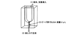
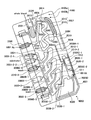
反応室について、図1、図2、図3、図4、図5、図6に示す実施例に基づいて説明する。図1に示される反応室ユニット1000Aは、反応室1011が後述の反応室ユニットにおける試薬・検体受け1012に連結して設けられており、反応室ユニットにおける試薬・検体受け1012の開口部1012Aと反対側に開口部1011Aを有する。反応室1011には、抗原および/または抗体を結合する担体1013が収納されている。また、図2、図3、図4、図5、図6にそれぞれ示される反応室ユニット1000B、1000C、1000D、1000Eの反応室1011は、反応室ユニットの管壁に隣接して設けられており、反応室ユニットにおける試薬・検体受け1012の開口部1012Aと反対側に開口部1011Aを有する。さらに、開口部1011は、チップ本体の廃液槽4020に連通する(図37、図39、図41参照)。これにより、抗原抗体反応および検出に用いる検体、試薬を外部に漏らすことなく廃液槽に保持することが出来る。また、図2、図3、図4および図6に示される反応室ユニット1000B、1000C、1000Dにおける試薬・検体受けのように、開口部1012Aは、各反応室ユニットが後述の図39に示す分析チップのチップ本体に装着可能な構造の場合には、反応室ユニットにおける試薬・検体受け1012の上部側面にあってもよい。これにより、図37、図38−1、図38−2、図38−3、図39、図40−1、図40−2、図40−3、図41に示す本発明の分析チップのチップ本体に反応室ユニットを装着した場合、後述の不溶性成分分離部に連通する流路および多段送液部に連通する流路との接続部を設ける位置を、反応室ユニットにおける試薬・検体受け1012の上部方向または側面方向に設けることが出来、設計の自由度を増すことができる。開口部1012Aは、さらに好ましくは試薬・検体受け1012の内周側側面に設けられる。これにより、回転時に確実に検体および試薬を、漏らすことなく試薬・検体受けに送液することができる。
The reaction chamber will be described based on the examples shown in FIGS. 1, 2, 3, 4, 5, and 6. FIG. A
反応室は、開口部(第2の開口部)を備えることができる。開口部の位置は、後述の反応室ユニットにおける試薬・検体受けを設ける場合には該受けと反対側であることが望ましい。この開口部には、更に担体の堰き止め手段を設けることができ、これにより反応室ユニットから担体が漏れないよう保持することができる。堰き止め手段としては、例えば担体の粒径より開口径の小さい金網やフィルタまたは狭隘構造を用いることができる。金網の場合、適当なサイズの金網(例えば開口部分が20μm×20μmのもの)を開口部にプレスして堰き止め手段とすることができる。また、フィルタの場合はセルロース・アセテート製フィルタ等を開口部に圧入して得ることができる。なお、堰き止め手段は金網、フィルタには限定されず、キャップ等を用いることができる。また、狭隘構造の場合には反応室の下流部に担体の粒径より小さい間隙を有する狭隘部を設けた構造を用いることが出来る。 The reaction chamber can include an opening (second opening). The position of the opening is preferably on the opposite side of the reagent / sample receiver in the reaction chamber unit described later. The opening can be further provided with a carrier damming means, whereby the carrier can be held so as not to leak from the reaction chamber unit. As the damming means, for example, a wire mesh, a filter or a narrow structure having an opening diameter smaller than the particle diameter of the carrier can be used. In the case of a wire mesh, a wire mesh of an appropriate size (for example, an opening having a size of 20 μm × 20 μm) can be pressed into the opening to form a damming means. In the case of a filter, it can be obtained by press-fitting a cellulose acetate filter or the like into the opening. The damming means is not limited to a wire mesh or a filter, and a cap or the like can be used. In the case of a narrow structure, a structure in which a narrow portion having a gap smaller than the particle size of the support is provided in the downstream portion of the reaction chamber can be used.
反応室の開口部を堰き止め手段としてのフィルタで塞いだ場合の構成につき、図2に示す実施例を例にとって説明する。図2は、反応室ユニット1000Bの縦断面を模式的に示す図である。反応室1011の開口部1011A´は、反応室1011よりも幅が広く取られており、この部分1011A´にフィルタが圧入される。なお、堰き止め手段を設けるにあたり開口部の幅が広く取られている必要はなく、図1に示す反応室ユニット1000A、図3に示す反応室ユニット1000Cなどの開口部1011Aにおいて金網を開口部にプレスして堰き止め手段(図示せず)を設けることができる。
The configuration when the opening of the reaction chamber is closed with a filter as a blocking means will be described with reference to the embodiment shown in FIG. FIG. 2 is a diagram schematically showing a longitudinal section of the
また、反応室の開口部を狭隘構造とした場合を図4および図5に示す実施例を例にとり説明する。図4に示す反応室ユニット1000D、図5の反応室ユニットの1000Eにおいて、反応室1011の開口部1011A”の流路径は担体の径よりも狭いため、担体の流出を防ぐことができる。
The case where the opening of the reaction chamber has a narrow structure will be described with reference to the embodiment shown in FIGS. In the
〔担体〕
反応室には、抗原および/または抗体が結合した担体が収容される。担体の収容数は1つ以上であればよく、免疫分析の効率を上げる観点から、複数の担体を収容することが好ましい。また、複数の担体を反応室に収容することにより、液体に対して圧力損失が生じるため、反応室ユニットにおける試薬・検体受けに液体を注入しても重力による作用だけでは液体は反応室を通じて流出しないという効果もある。
[Carrier]
The reaction chamber contains a carrier to which an antigen and / or an antibody is bound. The number of carriers to be accommodated is one or more, and it is preferable to accommodate a plurality of carriers from the viewpoint of increasing the efficiency of immunoassay. In addition, since a plurality of carriers are accommodated in the reaction chamber, pressure loss occurs with respect to the liquid. Therefore, even if liquid is injected into the reagent / sample receiver in the reaction chamber unit, the liquid flows out through the reaction chamber only by the action of gravity. There is also an effect of not.
担体の形状は、球状、楕円球状などのマイクロビーズのほか、円柱、多角柱などのいわゆるマイクロロッド、板状のマイクロプレートであってもよい。
担体のサイズは、反応室のサイズによるが、担体の形状にかかわらず、短径が1μmから1000μm、好ましくは10μmから200μmの範囲であることが好ましい。
The shape of the carrier may be a so-called microrod such as a cylinder or a polygonal column, or a plate-like microplate, in addition to spherical or elliptical microbeads.
The size of the carrier depends on the size of the reaction chamber, but regardless of the shape of the carrier, the minor axis is preferably in the range of 1 μm to 1000 μm, preferably 10 μm to 200 μm.
担体の材料は特に限定されず、ガラス、セラミック(例えばイットリウム部分安定化ジルコニア)、金属(例えば金、白金、ステンレス)、樹脂(例えばナイロンやポリスチレン、ポリビニルアルコール、ポリメチルメタクリレート、ポリアクリルアミド)、アガロース等を用いることができるが、この中でも樹脂、特にポリスチレン、ポリメチルメタクリレートが好ましい。
反応室に複数の担体が収納される場合、各担体の形状、サイズ、材料は均一であってもよいし、多様であってもよい。また、反応室に格納する担体のすべてに抗原および/または抗体が結合されている必要はなく、何も結合しない担体が一部含まれていてもよい。
The material of the carrier is not particularly limited, and glass, ceramic (eg, yttrium partially stabilized zirconia), metal (eg, gold, platinum, stainless steel), resin (eg, nylon, polystyrene, polyvinyl alcohol, polymethyl methacrylate, polyacrylamide), agarose Among them, resins, particularly polystyrene and polymethyl methacrylate are preferable.
When a plurality of carriers are stored in the reaction chamber, the shape, size, and material of each carrier may be uniform or varied. In addition, it is not necessary that antigens and / or antibodies are bound to all the carriers stored in the reaction chamber, and a part of the carriers that do not bind anything may be included.
担体に結合させる抗原および/または抗体は、種々の抗体、FabフラグメントやF(ab')2フラグメントのような抗体の抗原結合性断片、並びに種々の抗原などの中から、免疫分析における検体中の被検物質に特異的に結合する抗原や抗体を適宜選択することができ、1種類であっても、また複数種類であってもよい。抗原や抗体の担体への結合密度、結合数、結合様式などに特に制限はない。 Antigens and / or antibodies to be bound to the carrier can be selected from various antibodies, antigen-binding fragments of antibodies such as Fab fragments and F (ab ′) 2 fragments, various antigens, and the like in samples in immunoassays. Antigens and antibodies that specifically bind to the test substance can be selected as appropriate, and there may be one kind or plural kinds. There are no particular restrictions on the binding density, number of bindings, binding mode, etc. of the antigen or antibody to the carrier.
担体に抗原および/または抗体を結合させる方法は、例えば、担体と抗原や抗体とを緩衝液等の溶液中で混合し接触し結合させる方法によることができる。接触による結合は、通常1時間から24時間(1日)、低温、一般には4℃から37℃の条件で、必要に応じて攪拌しながら実施することができる。得られた担体は、使用前に緩衝液、洗浄液等で洗浄してもよい。なお、結合方法はこれに限定されず、例えば抗原や抗体と担体とを親水性ポリマー(ポリエチレンイミン、ポリエチレングリコール、ポリビニルアルコール、ポリスルホン酸ナトリウム等)を含む架橋剤を使って化学的に結合させる方法などを利用することもできる。 The antigen and / or antibody can be bound to the carrier by, for example, a method in which the carrier and the antigen or antibody are mixed in a solution such as a buffer and contacted to bind. Bonding by contact can be carried out with stirring, if necessary, usually under conditions of 1 to 24 hours (1 day) at a low temperature, generally 4 ° C. to 37 ° C. The obtained carrier may be washed with a buffer solution, a washing solution or the like before use. The binding method is not limited to this. For example, a method of chemically binding an antigen or antibody and a carrier using a cross-linking agent containing a hydrophilic polymer (polyethyleneimine, polyethylene glycol, polyvinyl alcohol, sodium polysulfonate, etc.). Etc. can also be used.
反応室には、免疫分析のための検体や試薬が送り込まれる。検体についてはすでに説明したとおりである。試薬とは、免疫分析の際に用いられる検体以外の化学物質や薬剤を意味する。例えば、被検物質の検出等のための薬剤、物質、洗浄液などであり、更に具体的には、蛍光や酵素で標識された標識抗体(二次抗体)、抗原、洗浄液、蛍光もしくは発光基質等を挙げることができる。 Samples and reagents for immunoassay are sent into the reaction chamber. The specimen has already been described. A reagent means a chemical substance or a drug other than a specimen used in immunoassay. For example, drugs, substances, washing solutions, etc. for detection of test substances, and more specifically, labeled antibodies (secondary antibodies) labeled with fluorescence or enzymes, antigens, washing solutions, fluorescence or luminescent substrates, etc. Can be mentioned.
〔反応室ユニットにおける試薬・検体受け〕
反応室ユニットは、試薬・検体受けを備えることができる。これにより、直接反応室に試薬や検体を送り込む場合に比べて操作が容易である。すなわち、反応室をより狭い管状として、担体の収納密度を向上させて免疫分析の効率を高めることができる。
[Reagent / sample receiver in reaction chamber unit]
The reaction chamber unit can include a reagent / sample receiver. As a result, the operation is easier than in the case where the reagent or sample is directly fed into the reaction chamber. That is, the reaction chamber can be made into a narrower tube, so that the storage density of the carrier can be improved and the efficiency of immunoassay can be increased.
図1に示される反応室ユニット1000Aは、反応室1011に連結して反応室ユニットにおける試薬・検体受け1012が設けられており、反応室ユニットにおける試薬・検体受け1012は外部に開口部1012Aを有する。また、図2、図3、図4、図5、図6に示される反応室ユニット1000B、1000C、1000D、1000Eでも、同様に、反応室ユニットにおける試薬・検体受け1012が反応室1011に連結して設けられている。一部先に述べたが、図1に示される反応室ユニット1000A、図5に示される反応室ユニット1000Eにおいて開口部1012Aは上方に開口(すなわち、反応室の開口部1011の反対側)するのに対し、図2の反応室ユニット1000B,図3および図6に示される各反応室ユニット1000C、図4に示される反応室ユニット1000Dの開口部1012Aは、ユニット側面に開口する。
The
前記反応室ユニットにおける試薬・検体受けの容積(サイズ)は、前記反応室のそれよりも大きいことが好ましい。反応室が反応室ユニットにおける試薬・検体受けに比べて十分小さいことにより、被検物質の濃縮効果があるからであり、さらに反応室ユニットにおける試薬・検体受けに試薬や検体を保持させることが容易となるからである。具体的には例えば、反応室ユニットにおける試薬・検体受けの反応室に対する容積比が通常は100以上で、中でも100から5×10⁸の範囲で、特に100から3000の範囲で、適宜定められることが好ましい。ディスク上に分析機構を集積化させた従来技術では約15倍程度が限界であることから、上述の範囲とすることにより、被検物質の濃縮効果が、従来技術と比較して非常に大きいものとなる。 The volume (size) of the reagent / sample receiver in the reaction chamber unit is preferably larger than that in the reaction chamber. This is because the reaction chamber is sufficiently small compared to the reagent / sample receiver in the reaction chamber unit, so that there is an effect of concentrating the test substance, and it is easy to hold the reagent and sample in the reagent / sample receiver in the reaction chamber unit. Because it becomes. Specifically, for example, the volume ratio of the reagent / sample receiver to the reaction chamber in the reaction chamber unit is usually 100 or more, particularly in the range of 100 to 5 × 10 8 , particularly in the range of 100 to 3000. Is preferred. In the conventional technology in which the analysis mechanism is integrated on the disk, the limit is about 15 times. By setting the above range, the concentration effect of the test substance is very large compared to the conventional technology. It becomes.
なお、反応室ユニットにおける試薬・検体受けの容積は、一般には30μLから500mLであり、好ましくは30μLから1000μL(1mL)である。 The volume of reagent / sample receiver in the reaction chamber unit is generally 30 μL to 500 mL, preferably 30 μL to 1000 μL (1 mL).
一方、前記反応室ユニットにおける試薬・検体受けの送液方向の投影断面積(送液方向と垂直な面に投影したときの面積)と、前記反応室の送液方向の投影断面積の比は、通常は50以上であり、好ましくは100以上である。また、上限は、一般には10000以下とする。ディスク上に分析機構を集積化させた従来技術の場合、装置全体が2次元構造であるために該試薬・検体受けと反応室の送液方向の投影断面積比がせいぜい10数倍程度までしか差を着けられないが、本発明で用いる反応室ユニットは立体構造であるので、同面積比を拡大し、被検物質の濃縮効率を著しく向上させることができる。 On the other hand, the ratio of the projected cross-sectional area in the liquid feeding direction of the reagent / sample receiver in the reaction chamber unit (area when projected onto a plane perpendicular to the liquid feeding direction) and the projected cross-sectional area in the liquid feeding direction of the reaction chamber is Usually, it is 50 or more, preferably 100 or more. Moreover, generally an upper limit shall be 10,000 or less. In the case of the prior art in which the analysis mechanism is integrated on the disk, the entire apparatus has a two-dimensional structure, so that the projected cross-sectional area ratio in the liquid feeding direction between the reagent / sample receiver and the reaction chamber is at most about 10 times. Although there is no difference, since the reaction chamber unit used in the present invention has a three-dimensional structure, the area ratio can be increased and the concentration efficiency of the test substance can be remarkably improved.
さらに、前記反応室ユニットにおける試薬・検体受けの送液方向に対して平行方向の最大断面積と、前記反応室の送液方向に対して平行方向の最大断面積の比は、被検物質の濃縮効果を得る観点から、2から400であることが好ましい。なお、反応室ユニットにおける試薬・検体受けの送液方向に対して平行方向の最大断面積は、10mm2から200mm2とすることが好ましい。また、反応室の送液方向に対して平行方向の最大断面積は、0.5mm2から5mm2とすることが好ましい。 Further, the ratio of the maximum cross-sectional area in the direction parallel to the liquid feeding direction of the reagent / sample receiver in the reaction chamber unit to the maximum cross-sectional area in the direction parallel to the liquid feeding direction in the reaction chamber is the ratio of the test substance. From the viewpoint of obtaining a concentration effect, it is preferably 2 to 400. The maximum cross-sectional area in the direction parallel to the liquid feeding direction of the reagent / sample receiver in the reaction chamber unit is preferably 10 mm 2 to 200 mm 2 . The maximum cross-sectional area in the direction parallel to the liquid feeding direction in the reaction chamber is preferably 0.5 mm 2 to 5 mm 2 .
反応室ユニットにおける試薬・検体受けの形状は特に限定されず、円筒形、多角形などの各種形状から適宜選択することができるが、遠心力で試薬や検体を反応室へ円滑に送り込む観点から、横断面の面積が、反応室への接続側に向かって徐々に狭くなる形状であることが好ましい。例えば、図1に示す反応室ユニット1000Aにおける反応室ユニットにおける試薬・検体受け1012の形状は、基本的には直方体であり、反応室1011側の4つの隅の角が丸みを帯びた形状となっている。一方、図2、図3、図4および図5のそれぞれに示す反応室ユニット1000B,1000C,1000D、1000Eにおける反応室ユニットにおける試薬・検体受け1012の形状も、基本的には直方体であり、4つの側面が反応室側で反応室に向けて絞られている。
The shape of the reagent / sample receiver in the reaction chamber unit is not particularly limited and can be appropriately selected from various shapes such as a cylindrical shape and a polygonal shape, but from the viewpoint of smoothly feeding the reagent and sample into the reaction chamber by centrifugal force, It is preferable that the cross-sectional area has a shape that gradually narrows toward the connection side to the reaction chamber. For example, the shape of the reagent /
反応室ユニットにおける試薬・検体受けは反応室に直接接続しており、反応室と反対側に開口部(第1の開口部)を有する。外部への開口部の形状は特に問わないが、注入した試薬や検体が外に漏出しない程度の大きさで適宜定めることができる。例えば、短径が1mmから100mm、好ましくは1から20mmの範囲となるよう適宜定めることができる。 The reagent / sample receiver in the reaction chamber unit is directly connected to the reaction chamber, and has an opening (first opening) on the opposite side to the reaction chamber. Although the shape of the opening to the outside is not particularly limited, it can be appropriately determined in such a size that the injected reagent or specimen does not leak out. For example, the minor axis can be appropriately determined so as to be in the range of 1 mm to 100 mm, preferably 1 to 20 mm.
反応室ユニットは、チップ本体から着脱可能であることが好ましい。これにより、反応室ユニットを、チップ本体とは異なる材料を用いて形成することが容易となり、チップ本体が求められる性質とは切り離して、反応室ユニットとして求められる特性に応じた性質の材料を用いることができるので好ましい。また、反応室ユニットを取り外して測定することが出来るため、廃液槽からのノイズ源の影響を抑えることもできる。また、担体を予め反応室ユニットに充填することも容易となる。 The reaction chamber unit is preferably removable from the chip body. This makes it easy to form the reaction chamber unit using a material different from that of the chip body, and uses a material having properties corresponding to the characteristics required for the reaction chamber unit, apart from the properties required of the chip body. This is preferable. Moreover, since the reaction chamber unit can be removed and measured, the influence of the noise source from the waste liquid tank can be suppressed. It is also easy to fill the reaction chamber unit with the carrier in advance.
〔反応室ユニットのサイズ・形状〕
反応室ユニットのサイズおよび形状は、チップ本体の大きさにより定めることができる。例えば、短径は通常1mmから20mm、好ましくは2mmから10mm、高さは通常2mmから100mm、好ましくは5mmから20mmの範囲で定めることが出来る。
[Reaction chamber unit size and shape]
The size and shape of the reaction chamber unit can be determined by the size of the chip body. For example, the minor axis is usually 1 mm to 20 mm, preferably 2 mm to 10 mm, and the height is usually 2 mm to 100 mm, preferably 5 mm to 20 mm.
また、反応室ユニットの本体の形状も、成形の容易さも考慮して定めることができ、立方体、多角柱形、円柱形、角錐形、円錐形などから適宜選択することができる。 In addition, the shape of the main body of the reaction chamber unit can be determined in consideration of ease of molding, and can be appropriately selected from a cube, a polygonal column, a cylinder, a pyramid, a cone, and the like.
3.不溶性成分分離部
本発明の分析チップは、遠心力の作用により、検体としての懸濁液中の不溶性成分を分離液から分離して沈降可能であり、また重力の作用により前記分離液を分取し、次いで遠心力の作用により反応室ユニットに移送可能である、不溶性成分分離部を有する。
3. Insoluble component separation unit The analysis chip of the present invention can separate and precipitate insoluble components in a suspension as a specimen from a separated solution by the action of centrifugal force, and also separates the separated solution by the action of gravity. Then, it has an insoluble component separation part that can be transferred to the reaction chamber unit by the action of centrifugal force.
不溶性成分分離部は、回転により懸濁液から不溶性成分を分離するための部分である。不溶性成分分離部の分析チップ上の位置については特に制限はないが、好ましくは分析チップの回転時に、反応室よりも内周側となる位置に設けられることが好ましい。さらに、分析チップの回転時に多段送液部よりも重力方向の上部に位置させることが好ましい。 The insoluble component separator is a portion for separating the insoluble component from the suspension by rotation. The position of the insoluble component separation part on the analysis chip is not particularly limited, but it is preferably provided at a position on the inner peripheral side of the reaction chamber when the analysis chip is rotated. Furthermore, it is preferable that the analysis chip is positioned above the multi-stage liquid feeding unit in the direction of gravity when the analysis chip is rotated.
不溶性成分分離部は、懸濁液保持槽、分離液保持槽、不溶性成分保持槽を備える。これらの槽は、本発明の分析チップの回転時、すなわち回転装置に設置された状態において内周側(回転軸寄りの側)から、懸濁液保持槽、分離液保持槽、不溶性成分保持槽の順に配置される。 The insoluble component separation unit includes a suspension holding tank, a separation liquid holding tank, and an insoluble component holding tank. These tanks are a suspension holding tank, a separation liquid holding tank, an insoluble component holding tank from the inner peripheral side (side closer to the rotating shaft) when the analysis chip of the present invention is rotated, that is, in a state of being installed in the rotating device. Arranged in this order.
〔懸濁液保持槽〕
懸濁液保持槽は、懸濁液を保持可能な槽である。懸濁液は、通常回転開始前(回転停止時)に、流路、開口部または通気穴により、懸濁液保持槽に予め貯液される。
(Suspension holding tank)
The suspension holding tank is a tank capable of holding a suspension. The suspension is preliminarily stored in the suspension holding tank by a flow path, an opening, or a vent hole before starting rotation (when rotation is stopped).
〔分離液保持槽〕
分離液保持槽は、分析チップの回転時に懸濁液保持槽より送液された懸濁液のうち、分離された液状成分である分離液を分析チップの回転時に保持可能な槽である。分離液保持槽の形状は、分析チップの回転時に一時的に分離液を保持可能であればよいので必ずしも槽構造である必要はなく、流路の壁面の一部分(例えば流路の湾曲部の窪み部分など)であってもよい。
[Separation liquid holding tank]
The separation liquid holding tank is a tank that can hold a separated liquid component, which is a separated liquid component, of the suspension sent from the suspension holding tank when the analysis chip is rotated, when the analysis chip is rotated. The shape of the separation liquid holding tank is not necessarily required to be a tank structure as long as the separation liquid can be temporarily held when the analysis chip is rotated, and a part of the wall surface of the flow path (for example, the depression of the curved portion of the flow path). Part etc.).
〔不溶性成分保持槽〕
不溶性成分保持槽は、分析チップの回転時に懸濁液保持槽より送液された懸濁液から分離された不溶性成分を保持可能な槽である。
(Insoluble component holding tank)
The insoluble component holding tank is a tank capable of holding the insoluble component separated from the suspension fed from the suspension holding tank when the analysis chip is rotated.
懸濁液保持槽、分離液保持槽、不溶性成分保持槽のサイズは、それぞれ懸濁液、分離液、不溶性成分を保持するのに十分な容積があればよい。各槽の容積は、例えば、懸濁液保持槽は10マイクロリットル(μL)から6000マイクロリットル、分離液保持槽は3マイクロリットルから4000マイクロリットル、不溶性成分保持槽は3マイクロリットルから4000マイクロリットルの容量であることが好ましい。 The suspension holding tank, the separation liquid holding tank, and the insoluble component holding tank need only have sufficient volumes to hold the suspension, the separation liquid, and the insoluble component, respectively. The volume of each tank is, for example, 10 μL (μL) to 6000 μL for the suspension holding tank, 3 μL to 4000 μL for the separation liquid holding tank, and 3 μL to 4000 μL for the insoluble component holding tank. Preferably, the capacity is
懸濁液が血液である場合を例にとると、懸濁液保持槽は10マイクロリットルから6000マイクロリットルの血液が貯液できるサイズであることが好ましい。また、分離液保持槽は3マイクロリットルから2000マイクロリットルの血漿など血球以外の成分を回転時に貯液できるサイズであることが好ましい。さらに、不溶性成分保持槽は7マイクロリットルから4000マイクロリットルの血球を含む成分を回転時に保持できるサイズであることが好ましい。 Taking the case where the suspension is blood as an example, the suspension holding tank is preferably of a size that can store 10 to 6000 microliters of blood. Moreover, it is preferable that the separation liquid holding tank has a size capable of storing components other than blood cells such as 3 to 2000 microliters of plasma during rotation. Furthermore, the insoluble component holding tank is preferably of a size that can hold a component containing 7 to 4000 microliters of blood cells during rotation.
血液の場合には、不溶性成分である血液中の血球成分の割合が、通常40%から60%であるため、分離液保持槽と不溶性成分保持槽の容積比は、血球成分が分離液保持槽に混入しないように4:6より不溶性成分保持槽の方が大きいことが好ましく、特に3:7より大きくすることが好ましい。 In the case of blood, since the ratio of blood cell components in blood that is an insoluble component is usually 40% to 60%, the volume ratio between the separation liquid holding tank and the insoluble component holding tank is such that the blood cell component is the separation liquid holding tank. It is preferable that the insoluble component holding tank is larger than 4: 6, and it is particularly preferable that it be larger than 3: 7.
懸濁液が例えば尿である場合には、懸濁液保持槽は10マイクロリットルから6000マイクロリットルの尿が貯液できるサイズであることが好ましい。分離液保持槽は7マイクロリットルから4000マイクロリットルの尿上清を回転時に貯液できるサイズであることが好ましい。不溶性成分保持槽は3マイクロリットルから2000マイクロリットルの尿酸などの結晶や細胞などを含む成分を回転時に保持できるサイズであることが好ましい。 When the suspension is, for example, urine, the suspension holding tank is preferably sized to store 10 to 6000 microliters of urine. The separation liquid holding tank is preferably of a size capable of storing 7 to 4000 microliters of urine supernatant during rotation. The insoluble component holding tank is preferably of a size that can hold 3 microliters to 2000 microliters of components such as uric acid crystals and cells during rotation.
〔懸濁液保持槽、分離液保持槽および不溶性成分保持槽の位置〕
不溶性成分分離部において、懸濁液保持槽、分離液保持槽および不溶性成分保持槽の位置は、回転軸の内周側からこの順に配置されている。不溶性成分保持槽と分離液保持槽とは後述のように狭隘部で接続しているため、相互に隣接させることが望ましい。また、不溶性成分保持槽の方が分離液保持槽よりも外周側に位置させることが好ましい。さらに、懸濁液保持槽は、分離液保持槽よりも内周側に位置させることが好ましい。図10および図11に示す不溶性成分分離部を例にとって説明すると、懸濁液保持槽2001、分離液保持槽2002および不溶性成分保持槽2003は回転軸側(内周側)から回転軸から遠ざかる方向(外周側)に向かって、この順に並列的に配置されている。分離液保持槽2002と不溶性成分保持槽2003とは隣接し、これらの槽よりもくびれた(より細径の)狭隘部2010で接続(連通)されている。懸濁液保持槽2001は不溶性成分保持槽2003よりも上方かつ内周側に位置している。
[Position of suspension holding tank, separation liquid holding tank and insoluble component holding tank]
In the insoluble component separation unit, the positions of the suspension holding tank, the separation liquid holding tank, and the insoluble component holding tank are arranged in this order from the inner peripheral side of the rotating shaft. Since the insoluble component holding tank and the separation liquid holding tank are connected by a narrow portion as described later, it is desirable that they are adjacent to each other. Moreover, it is preferable that the insoluble component holding tank is positioned on the outer peripheral side of the separation liquid holding tank. Furthermore, the suspension holding tank is preferably located on the inner peripheral side with respect to the separation liquid holding tank. The insoluble component separation unit shown in FIGS. 10 and 11 will be described as an example. The
不溶性成分分離部においては懸濁液保持槽と不溶性成分保持槽が接続されている。すなわちこれらの2つの槽は、分離液保持槽を介さずに連結されている。これにより、懸濁液保持槽が分離液保持槽を介して不溶性成分保持槽と連通している従来の不溶性成分分離部と比較して、分離液保持槽と不溶性成分保持槽間の狭隘部に、遠心力により懸濁液が流入することがなく、閉塞や不溶性成分保持槽内への気泡の混入といった問題を起こすことがない。 In the insoluble component separation unit, a suspension holding tank and an insoluble component holding tank are connected. That is, these two tanks are connected without a separation liquid holding tank. As a result, compared to the conventional insoluble component separation section in which the suspension holding tank communicates with the insoluble component holding tank via the separation liquid holding tank, the narrow portion between the separation liquid holding tank and the insoluble component holding tank is formed. In addition, the suspension does not flow in due to centrifugal force, and there is no problem such as blockage or mixing of bubbles into the insoluble component holding tank.
図8−1、図8−2、図9、図10及び図11を参照して、従来の不溶性成分分離部の問題点および本発明における不溶性成分分離部の特色につき説明する。図8−1は、従来の不溶性成分分離部の一例を模式的に示す斜視図である。図8−2は、図8−1に示された従来の不溶性成分分離部を模式的に示す厚み方向から見た図である。図9は、従来の不溶性成分分離部の別の一例を模式的に示す平面図である。図10は、本発明の分析チップの不溶性成分分離部の一例を模式的に示す正面図である。図11は、本発明の分析チップの不溶性成分分離部の別の一例を模式的に示す正面図である。 The problems of the conventional insoluble component separation unit and the features of the insoluble component separation unit in the present invention will be described with reference to FIGS. 8-1, 8-2, 9, 10, and 11. FIG. FIG. 8-1 is a perspective view schematically illustrating an example of a conventional insoluble component separation unit. FIG. 8-2 is a diagram schematically showing the conventional insoluble component separation portion shown in FIG. 8-1 as viewed from the thickness direction. FIG. 9 is a plan view schematically showing another example of a conventional insoluble component separation unit. FIG. 10 is a front view schematically showing an example of the insoluble component separation part of the analysis chip of the present invention. FIG. 11 is a front view schematically showing another example of the insoluble component separation portion of the analysis chip of the present invention.
図8−1、図8−2および図9に示す従来の不溶性成分分離部においては、懸濁液保持槽2001、分離液保持槽2002および不溶性成分保持槽2003が、回転軸側からこの順番に並列的に接続されて配置されている。不溶性成分分離部を有するチップを回転させて懸濁液保持槽2001から分離液保持槽2002に送液された懸濁液のうち、不溶性成分は、不溶性成分保持槽2003にトラップされることになるが、その際、分離液保持槽2002と不溶性成分保持槽2003との間の狭隘部2010を通る必要があり、懸濁液がこの狭隘部2010の内周側(回転軸に向かう側)から外周側(回転軸から遠ざかる側)に向けて遠心力により通過する際、不溶性成分が狭隘部2010を閉塞してしまうという問題があった。また、狭隘部2010を通じて遠心力により懸濁液中の不溶性成分が流入するため、不溶性成分保持槽2003内の気体の逃げ場が無く、結果として不溶性成分保持槽2003中に気泡が入りやすいという問題があった。
In the conventional insoluble component separation section shown in FIGS. 8-1, 8-2 and 9, the
一方、図10および図11に一例として示す本発明の分析チップの不溶性成分分離部においては、懸濁液保持槽2001、不溶性成分保持槽2003および分離液保持槽2002の順に送液できるように接続されており、かつ狭隘部2010の外周側の不溶性成分保持槽2003から内周側の分離液保持槽2002に分離液または懸濁液が送液される機構であるため、遠心力により分離された不溶性成分は直接的に不溶性成分保持槽2003にトラップ(保持)され狭隘部2010での不溶性成分による閉塞は起こらない。また、不溶性成分保持槽2003は、狭隘部2010と、懸濁液保持槽との不溶性成分保持槽2003側の接続部2011の少なくとも2カ所の接続部を有しているため、接続部2011から不溶性成分保持槽2003に流入した懸濁液量だけ、不溶性成分保持槽2003の内部の気体は狭隘部2010を通じて分離液保持槽2002側に安定して流出することとなり、不溶性成分保持槽2003内への気泡の残存は起こらない。よって、不溶性成分保持槽と分離液との分離を安定して行うことができる。
On the other hand, in the insoluble component separation part of the analysis chip of the present invention shown as an example in FIGS. 10 and 11, the
本発明の分析チップの不溶性成分分離部において、不溶性成分保持槽2003における懸濁液保持槽2001との接続部2011は、分離液保持槽2002と不溶性成分保持槽2003との間の狭隘部2010より外周側に位置する。「狭隘部2010より外周側」とは、狭隘部2010の不溶性成分保持槽2003側の開口部よりも外周側に位置することを意味する。
In the insoluble component separation part of the analysis chip of the present invention, the
さらに、不溶性成分保持槽2003と懸濁液保持槽2001との接続部2011、すなわち懸濁液導入路2006の不溶性成分保持槽2003側の開口部は、不溶性成分保持槽2003の外周側壁面に位置させることが好ましい。これにより、懸濁液の分離液保持槽2002への混入をさらに効率的に防止することができるとともに、不溶性成分保持槽2003内部への気泡の残存をより効果的に抑制することができる。「不溶性成分保持槽2003の外周側壁面」とは、本発明の分析チップを回転させた際の不溶性成分保持槽の側壁2003のうち、より外周側に位置する側壁の壁面である。
Furthermore, the
〔懸濁液導入路〕
懸濁液保持槽2001と不溶性成分保持槽2003との間の接続は、開口部により相互に直接連結されていてもよいし、例えばトンネル状の流路である懸濁液導入路2006により連結されていてもよい。このうち懸濁液導入路2006により連結することが好ましい。懸濁液導入路2006を設けることにより、不溶性成分保持槽2003において懸濁液保持槽2001との接続部2011を不溶性成分保持槽2003の外周側壁面に設ける場合にも、懸濁液保持槽2001の位置や形状の自由度が高まるので好ましい。
[Suspension introduction path]
The connection between the
懸濁液導入路2006は、懸濁液保持槽2001から外周方向に延伸し不溶性成分保持槽2003に接続されて開口する。懸濁液導入路2006の不溶性成分保持槽2003との接続部2011は、不溶性成分保持槽2003と懸濁液保持槽2001との接続部についてすでに説明した構成と同様であり、不溶性成分保持槽2003と分離液保持槽2002との間の狭隘部よりも外周側に位置することが好ましく、特に、不溶性成分保持槽2003の外周側壁面に位置することが好ましい。かかる接続部2011が狭隘部2010よりも外周側に位置することにより、閉塞や不溶性成分保持槽2003内での気泡の混入を引き起こすことなく、不溶性成分の分離を円滑に進めることができる。
The
図10および図11に示す本発明の分析チップにおける不溶性成分分離部の構成例では、いずれも懸濁液導入路2006が懸濁液保持槽2001と不溶性成分保持槽2003との間に設けられている。図10に示される不溶性成分分離部では、懸濁液導入路2006と不溶性成分保持槽2003との接続部2011、すなわち懸濁液導入路2006の不溶性成分保持槽2003側の開口部は、狭隘部2010よりも外周側に位置しており、かつ、不溶性成分保持槽2003の外周側上端の側面に位置している。図11に示される不溶性成分分離部では、懸濁液導入路2006は後述するオーバーフロー流路2007と合流した後に、不溶性成分保持槽2003に接続部2012として開口して接続している。かかる接続部2012は、狭隘部2010よりも外周側に位置しており、かつ、不溶性成分保持槽2003の外周側側面に位置している。
In the configuration example of the insoluble component separation unit in the analysis chip of the present invention shown in FIGS. 10 and 11, the
懸濁液導入路2006のサイズ(径、流路長など)には特に制限はなく、懸濁液が通液可能であればよい。短径は例えば通常10マイクロメートルから1000マイクロメートルであり、50マイクロメートルから500マイクロメートルであることが好ましい。長さは例えば通常1マイクロメートルから100ミリメートルであり、10マイクロメートルから50ミリメートルであることが好ましい。
The size (diameter, flow path length, etc.) of the
本発明の分析チップにおける不溶性成分分離部には、懸濁液や分離液などの液体が通過せず、単に気体が懸濁液保持槽2001と分離液保持槽2002との間を通過するだけの通気用の流路が設けられていてもよい。
A liquid such as a suspension or a separation liquid does not pass through the insoluble component separation part of the analysis chip of the present invention, and the gas simply passes between the
〔狭隘部〕
本発明の分析チップにおける不溶性成分分離部において、分離液保持槽2002と不溶性成分保持槽2003とは、上述のように狭隘部2010により接続されている。すなわちこれらの槽の接続部は狭隘なくびれ状の構造であればよく、狭隘な開口部で連結されていてもよいし、微細な流路で連結されていてもよい。図10および図11に示す不溶性成分分離部の構成例では、狭隘部2010は分離液保持槽2002と不溶性成分保持槽2003とを連通する開口部である。狭隘部のサイズは、横断面の短径が通常5マイクロメートルから5000マイクロメートルであり、中でも10マイクロメートルから1000マイクロメートルであることが好ましい。懸濁液中の不溶性成分が通りにくいサイズであることが好ましいので短径が10マイクロメートルから100マイクロメートルの範囲であることが好ましい。また、狭隘部が流路である場合、流路の長さは比較的短いことが好ましく、通常は10マイクロメートルから10000マイクロメートル、好ましくは100マイクロメートルから1000マイクロメートルである。
[Narrow part]
In the insoluble component separation part in the analysis chip of the present invention, the separation
不溶性成分保持槽2003において、狭隘部2010への開口部はより上方に位置することが好ましい。これにより、回転停止時に不溶性成分保持槽2003内や懸濁液導入路2006内および後述するオーバーフロー流路内の不溶性成分が、分離液保持槽2002に混入することを効果的に防止することができる。「上方に位置する」とは、回転停止時に不溶性成分保持槽2003の上半分部分にあることを示す。特に、不溶性成分保持槽2003の上側のかつ内周側の壁面に位置すると、回転停止時に比重の大きな不溶性成分が流出し難くなるので好ましい。図10および図11に示される構成例で説明すると、くびれ状の狭隘部2010は、不溶性成分保持槽2003の壁面のうち、回転軸からみて上側のかつ内周側の壁面に位置している。
In the insoluble
〔分離液送液路〕
本発明の分析チップにおける不溶性成分分離部においては、分離液保持槽2002に分離液送液路2004を設けることができる。本発明における分離液送液路2004は、回転中に分離され、分離液保持槽2002に蓄積された分離液(液状成分)を、回転停止時に重力の作用により重力方向に落下させることで分離液保持槽から排出し、次いで次の回転時に遠心力の作用により反応室ユニットへ送液する機能を有する。分離液送液路2004は、分離液保持槽2002から重力方向に延伸することが好ましく、さらに、重力方向且つ外周側に延伸することがより好ましい。すなわち、本発明における分離液送液路2004は、重力方向に伸びる流路の途中で、回転軸を基準として外周方向に屈曲している屈曲部を有することが好ましい。これにより、再度の回転時に、分離液を、遠心力を利用して送液することができることから、分離液の逆流や液残りを防ぎ、効率よく分離液を回収し分取することができるとともに、分取された分離液全量を確実に反応室に送液することができる。
[Separated liquid feed path]
In the insoluble component separation part in the analysis chip of the present invention, the separation
本発明における分離液送液路は、重力での送液を素早く確実に行うため、少なくともその一部において重力方向に延伸することが好ましい。さらに、分離液送液路の少なくとも一部が、鉛直方向に対して45度以下の角度をなすことが好ましい。 In order to perform liquid feeding by gravity quickly and reliably, it is preferable that at least a part of the separation liquid feeding path in the present invention extends in the direction of gravity. Furthermore, it is preferable that at least a part of the separation liquid feeding path forms an angle of 45 degrees or less with respect to the vertical direction.
また分離液送液路は、分離液送液路の少なくとも一部と回転軸とがなす角度が、45度以下であることが好ましい。さらに、分離液送液路の少なくとも一部は回転軸に対し略平行に配置することが好ましい。回転軸が鉛直方向である場合、分離液送液路も少なくともその一部において略鉛直方向に延伸することが好ましい。 In addition, it is preferable that an angle formed by at least a part of the separation liquid feeding path and the rotation axis of the separation liquid feeding path is 45 degrees or less. Furthermore, it is preferable that at least a part of the separation liquid feeding path is arranged substantially parallel to the rotation axis. When the rotation axis is in the vertical direction, it is preferable that at least part of the separation liquid feeding path extends in the substantially vertical direction.
図10に示される構成例では、分離液保持槽2002に分離液送液路2004が接続され、分離液送液路2004は、全体が重力方向に延伸した後、外周側に向かって延伸する。また、図11に示される構成例では、分離液送液路2004が試薬保持槽2005、分離液保持槽2002と共通の重力方向に延伸する流路を構成する。分離液送液路2004は、分離液保持槽2002側から順に、第1部分領域2004A、第2部分領域2004B及び第3部分領域2004Cを構成している。第1部分領域2004Aは、試薬保持槽2005、分離液保持槽2002と共通の流路を構成し、第1部分領域2004Aと第2部分領域2004Bとの接続部において分離液混合槽2021に接続している。分離液送液路2004は、第1部分領域2004Aと第2部分領域2004Bとの間において重力方向かつ外周側に向かって折り返されて(方向転換して)いる。第1部分領域2004Aと鉛直方向、すなわち回転軸のなす角度は約45度である。図10および図11には分離液送液路2004は分析チップの外周側へ延伸したところまでしか示さないが、分離液送液路2004は図37、図39、図41に示すように反応室ユニットに連通する。
In the configuration example shown in FIG. 10, a separation
本発明における分離液送液路2004は、分離液保持槽2002との接続部における流路断面積より小さな流路断面積となる部位を流路途中に有することが好ましい。より好ましくは、流路断面積が徐々に小さくなる部位を流路途中に有する。断面積が小さくなることにより、重力に加えて毛細管力を併せて利用できるため、重力による排出をより短時間で効率よく行うことができる。
The separation
本発明における分離液送液路2004は、少なくともその内壁面の一部において親水的な表面を有することが好ましい。これにより、毛細管力を有効に利用できることから、重力による排出をさらに短時間で、確実に行うことができる。分離液送液路2004が角柱もしくは角錐状の形状の場合、好ましくは、分離液送液路を形成する2以上の内壁面、最も好ましくは流路を形成する全ての内壁面が親水的であることが好ましい。
In the present invention, the separation
〔プレフィルター部〕
分離液送液路にはプレフィルター部が設けられていることが好ましい。プレフィルター部は、分離液送液路の管の一部に槽として或いは管の一部として設けることができる。例えば、図39、図50−1、図50−2、図50−3、図50−4、図51−1および図51−2に示される分析チップでは、分離液送液路の一部にプレフィルター部4022が設けられている。
[Pre-filter part]
It is preferable that a pre-filter part is provided in the separation liquid feeding path. The prefilter portion can be provided as a tank or a part of the pipe in a part of the pipe of the separation liquid feeding path. For example, in the analysis chip shown in FIG. 39, FIG. 50-1, FIG. 50-2, FIG. 50-3, FIG. 50-4, FIG. 51-1, and FIG. A
プレフィルター部の形態としては、粒子(ビーズ)を充填したもの、紙、布等のフィルターを充填したものであってもよいが、粒子を充填したものが最も好ましい。粒子の形状は、球状、楕円球状などのマイクロビーズのほか、円柱、多角柱などのいわゆるマイクロロッド、板状のマイクロプレートであってもよい。粒子のサイズは、プレフィルター部のサイズにもよるが、粒子の形状にかかわらず、短径が1μmから1000μm、好ましくは10μmから200μmの範囲であることが好ましい。 The form of the pre-filter part may be one filled with particles (beads) or one filled with a filter such as paper or cloth, but one filled with particles is most preferred. The shape of the particles may be not only microbeads such as spherical and elliptical spheres, but also so-called microrods such as cylinders and polygonal columns, and plate-like microplates. Although the size of the particles depends on the size of the prefilter part, the minor axis is preferably in the range of 1 μm to 1000 μm, preferably 10 μm to 200 μm, regardless of the shape of the particles.
粒子の材料は特に限定されず、ガラス、セラミック(例えばイットリウム部分安定化ジルコニア)、金属(例えば金、白金、ステンレス)、樹脂(例えばナイロンやポリスチレン、ポリビニルアルコール、ポリメチルメタクリレート、ポリアクリルアミド)、アガロース等を用いることができるが、この中でもポリスチレン、ポリメチルメタクリレートが好ましい。 The material of the particles is not particularly limited, and glass, ceramic (for example, yttrium partially stabilized zirconia), metal (for example, gold, platinum, stainless steel), resin (for example, nylon, polystyrene, polyvinyl alcohol, polymethyl methacrylate, polyacrylamide), agarose Among them, polystyrene and polymethyl methacrylate are preferable.
プレフィルター部に複数の粒子が収納される場合、各粒子の形状、サイズ、材料は均一であってもよいし、多様であってもよい。 When a plurality of particles are stored in the prefilter portion, the shape, size, and material of each particle may be uniform or various.
〔試薬保持槽〕
図11に示すように、本発明の分析チップにおける不溶性成分分離部は、試薬保持槽2005を有するものであってもよい。本発明における試薬保持槽2005は、回転中に試薬を保持し、回転停止時に重力の作用により分離液保持槽2002に試薬を排出(供給、送液)する機能を有する。よって試薬保持槽2005は、試薬を蓄積するのに十分な容積があればよく、例えば、試薬10マイクロリットルから1000マイクロリットルを蓄積できる程度であればよい。
(Reagent holding tank)
As shown in FIG. 11, the insoluble component separation unit in the analysis chip of the present invention may have a
試薬保持槽2005は、分離液保持槽2002の上方に設けられている。試薬保持槽2005と分離液保持槽2002とは流路により互いに接続することが好ましい。これにより、分析チップの停止時に、試薬を重力の作用により分離液保持槽2002に送液することができる。実際には、試薬保持槽2005は、回転時に試薬を一時的に保持することができればよいので、分離液保持槽2002と同様に槽の形になっていなくても、すなわち流路状であってもよく、試薬保持槽2005と分離液保持槽2002とを共通の流路のそれぞれ一部分として設けることも可能である。
The
本発明における試薬保持槽2005は、その内壁面の少なくとも一部が疎水的な表面を有することが好ましい。疎水的表面による撥水性を利用し、回転停止時に試薬保持槽2005から分離液保持槽2002に、試薬を効率よく、短時間で、また高い回収率で排出することが可能になる。試薬保持槽2005を形成する2以上の内壁面、最も好ましくは試薬保持槽を形成する全ての内壁面は、疎水的であることが好ましい。
The
図11に示される不溶性成分分離部の構成例では、試薬保持槽2005が分離液保持槽2002の上方に設けられ、試薬保持槽2005、分離液保持槽2002から分離液送液路2004が内周側下方に延伸し、分離液送液路2004の折り返し部2004Aで向きを変えて外周側に延伸する。一方、分離液送液路2004と接続し、分離液と試薬を混合するための分離液混合槽2021を設けることができる。これにより反応室ユニットに分離液を送液する前に試薬を充分に混合することができるため、測定が安定化する。例えば、図11では分離液送液路2004の第1部分領域2004Aと第2部分領域Bとの間から分離液混合槽2021が分岐し、上方に延伸し中途で行き止まって末端部を形成している。また例えば、図37、図39、図41に示される分析チップではこのような分離液混合槽2021が図11に示されるものよりも大きな容量の槽として設けられている。
In the configuration example of the insoluble component separation unit shown in FIG. 11, the
本発明における試薬は先に定義したとおりであり、分離液保持槽を洗浄する機能や、分離液を希釈する機能を有していてもよい。また、分離液中の特定の成分と反応する試薬としての機能を有していてもよい。具体的には分離液中の特定の成分と反応する抗体や抗原、酵素、核酸などを含んでいてもよい。例えば標識抗体を試薬として用いることで、槽内の洗浄と抗原抗体反応とを同時に行うこともできる。試薬の具体例としては、界面活性剤を含む溶液や、グリセロールなどの安定化剤を含む溶液、標識抗体や標識抗原、酵素を含むタンパク質溶液、酵素反応の基質溶液などが挙げられる。従って、分離液混合槽2021では分離液と試薬が混合し、混合した溶液中で被検物質と試薬中の特定の成分とを反応させることもできる。
The reagent in the present invention is as defined above, and may have a function of washing the separation liquid holding tank and a function of diluting the separation liquid. Moreover, you may have a function as a reagent which reacts with the specific component in a separation liquid. Specifically, it may contain an antibody, an antigen, an enzyme, a nucleic acid or the like that reacts with a specific component in the separation liquid. For example, by using a labeled antibody as a reagent, washing in the tank and antigen-antibody reaction can be performed simultaneously. Specific examples of the reagent include a solution containing a surfactant, a solution containing a stabilizer such as glycerol, a labeled antibody or labeled antigen, a protein solution containing an enzyme, a substrate solution for an enzyme reaction, and the like. Accordingly, the separation liquid and the reagent are mixed in the separation
本発明における試薬は、重力での送液を迅速に行うため、界面活性剤を含んでいることが好ましい。界面活性剤を含むことにより、試薬保持槽2005から分離液保持槽2002に試薬が落下しやすくなり、試薬と分離液とが混合するまでの時間を早くすることが可能である。これにより、分析に必要な時間が短縮できると同時に、混合されている時間すなわち試薬と分離液との反応時間をより厳密に制御することができる。
The reagent in the present invention preferably contains a surfactant in order to rapidly carry liquid by gravity. By including the surfactant, the reagent easily falls from the
〔試薬貯液槽〕
不溶性成分分離部においては、試薬保持槽2005に接続される試薬貯液槽2009を設けることができる。これにより、試薬保持槽2005に洗浄液を予め保持する必要がない。したがって、試薬貯液槽2009を設ければ、試薬保持槽2005は回転時に保持できる構造でありさえすればよいため、試薬保持槽2005のサイズや形状の自由度が高まる。試薬貯液槽2009のサイズは試薬を貯液できる範囲で適宜定めることができ、試薬10マイクロリットルから1000マイクロリットルを蓄積できればよく、通常は槽の容積が20マイクロリットルから1500マイクロリットルであり、中でも50マイクロリットルから500マイクロリットルであることが好ましい。試薬保持槽2005と試薬貯液槽2009とはそれぞれの槽に連通する開口部で接続されるものであってもよいし、試薬導入路2016で接続されるものであってもよい。なお、本発明における分析チップが後述の試薬リザーバユニットを有する場合には、試薬貯液槽2009は試薬リザーバユニットの試薬貯液槽の一つとして設けることが可能である。
[Reagent storage tank]
In the insoluble component separation unit, a
図11に示される不溶性成分分離部の構成例では、試薬貯液槽2009が試薬保持槽2005の下部かつ内周側に設けられている。試薬保持槽2005と試薬貯液槽2009とは、試薬貯液槽2009から外周側上方に延伸する試薬導入路2016にて接続されている。試薬貯液槽2009、試薬保持槽2005にはそれぞれ通気穴2017、2023が設けられている。本発明の分析チップの不溶性成分分離部においては、試薬貯液槽2009が試薬保持槽2005の内周側に位置し、試薬導入路2016で連結された構造をとることにより、試薬貯液槽2009内に予め貯液された試薬が、回転による遠心力により試薬導入路2016を介して試薬保持槽2005に保持されることになる。また、試薬貯液槽2009に通気穴2017を設けることにより試薬貯液槽2009から試薬保持槽2005への遠心力による試薬の移動を効率的に行うことができる。回転の停止により試薬保持槽2005内に保持されていた試薬は分離液保持槽2002を洗浄し、重力方向に延びる分離液送液路2004に、分離液保持槽2002に蓄積された分離液を押し出すことができる。一方試薬保持槽2005に通気穴2023を設けることにより、回転の停止による試薬の重力方向への移動を効率的に行うことが可能となる。
In the configuration example of the insoluble component separation unit shown in FIG. 11, the
さらに図11に示される不溶性成分分離部においては、試薬保持槽2005から分離液保持槽2002に試薬が移動する際、試薬の移動を効率的に行うため、分離液保持槽2002と試薬保持槽2005とをつなぐ、気体が移動するための流路(気体流路)2025が設けられている。
Further, in the insoluble component separation unit shown in FIG. 11, when the reagent moves from the
〔試薬導入路〕
試薬導入路は、試薬貯液槽と試薬保持槽とを連通する流路である。その例は、図11を例に挙げて説明したとおりである。
[Reagent introduction path]
The reagent introduction path is a flow path that connects the reagent storage tank and the reagent holding tank. The example is as described with reference to FIG.
試薬導入路は、第1の回転速度による回転時に、遠心力の作用により、液体を第2の貯液槽から第2の保持槽や試薬保持槽に送液することが好ましい。従って、試薬導入路の好ましい態様は、後述の多段送液部の流路Eと同様である。 The reagent introduction path preferably feeds liquid from the second storage tank to the second holding tank or the reagent holding tank by the action of centrifugal force when rotating at the first rotation speed. Therefore, a preferred embodiment of the reagent introduction path is the same as the flow path E of the multistage liquid feeding unit described later.
〔オーバーフロー流路(懸濁液導入路もしくは不溶性成分保持槽)〕
例えば図11に示されるように、本発明の分析チップにおける不溶性成分分離部は、懸濁液保持槽2001、懸濁液導入路2006もしくは不溶性成分保持槽2003に接続するオーバーフロー流路2018および2007を有していてもよい。本発明におけるオーバーフロー流路は、懸濁液保持槽2001中の懸濁液を回転により不溶性成分保持槽2003および分離液保持槽2002に送液する際、送液する懸濁液の量もしくは回転中に分離液保持槽2002で形成される液面を規定し、その結果として、回転停止時に分取、回収される分離液の液量を規定する機能を付与するための流路である。オーバーフロー流路2018および2007を、懸濁液保持槽2001、懸濁液導入路2006もしくは不溶性成分保持槽2003に接続して設けることにより、懸濁液保持槽2001の懸濁液の量にかかわらず分取、回収される分離液の量を一定にすることができ、定量性を確保することができる。
[Overflow channel (suspension introduction channel or insoluble component holding tank)]
For example, as shown in FIG. 11, the insoluble component separation unit in the analysis chip of the present invention includes
不溶性成分分離部には、オーバーフロー流路2018および2007に接続して、オーバーフローした懸濁液を保持するための槽2024もしくは2019を設けることができる。槽2024および2019の位置は特に限定されないが、通常はオーバーフロー流路2018および2007の外周側にそれぞれ設けることができる。
A
本発明におけるオーバーフロー流路2007は、懸濁液導入路2006もしくは不溶性成分保持槽2003との接続部2012から一度内周側に延伸した後、折り返し部2014で外周側に折り返した構造をとる。これにより分析チップの回転時に、分離液保持槽2002内で形成される液面とオーバーフロー流路2007の折り返し部2014とが同一円周面上に規定されることになり、分離液保持槽2002における液面の高さを一定に規定することが出来る。
The
本発明におけるオーバーフロー流路2007は、好ましくは懸濁液導入路2006または不溶性成分保持槽2003との接続部2012から一旦内周側に延伸した後、外周側かつ重力方向に折り返した構造をとる。こうした構造とすることにより折り返し部2014から先のオーバーフロー流路2007中およびその先の槽に移動した液が、回転停止時に懸濁液導入路2006もしくは不溶性成分保持槽2003に逆流することを、重力の作用により防止することができ、その結果として定量性を確保することおよび不溶性成分の分離液保持槽2002への混入を効果的に防止することができる。
The
図11の不溶性成分分離部の構成例のオーバーフロー流路について具体的に説明する。オーバーフロー流路2007は懸濁液導入路2006に接続部2012で接続されている。オーバーフロー流路2007は、その前半部分2013で接続部2012から上方側かつ内周側に延伸し、折り返し部(折り返し部位)2014を経て後半部分2015において下方かつ外周側に延伸している。後半部分2015は、接続部2012とほぼ平行な位置の末端部2015Aにおいてオーバーフローした懸濁液を貯液する槽2019と接続する。
The overflow channel of the configuration example of the insoluble component separation unit in FIG. 11 will be specifically described. The
図41に示される分析チップにおける不溶性成分分離部に示すように、オーバーフロー流路2007は懸濁液導入路2006の途中である分析チップの回転内周側に設けられていてもよい。
As shown in the insoluble component separation portion in the analysis chip shown in FIG. 41, the
オーバーフロー流路2007は、オーバーフロー流路の折り返し部2014の内周側に、通気穴2008を設けることが好ましい。折り返し部2014に通気穴2008を設けることにより、回転時にオーバーフロー流路2007を満たした懸濁液によりサイフォン現象が起きることを完全に抑制することが可能となる。これにより、分離液や懸濁液が分離液保持槽2002や不溶性成分保持槽2003から流出することを防ぐことができる。
The
折り返し部2014に通気穴2008を設けた場合には、折り返し部2014までの内周側に延伸したオーバーフロー流路2007の前半部分2013内の液体が回転停止時に懸濁液導入路2006もしくは不溶性成分保持槽2003に逆流する危険性がある。これを防止するため、折り返し部2014までの内周側に延伸したオーバーフロー流路2007の容積を、不溶性成分保持槽2003の容積よりも小さくすることが望ましい。例えば不溶性成分保持槽2003の容積に対する内周側に延伸したオーバーフロー流路2007の容積は、通常は20%以下であり好ましくは10%以下の容積とすることができる。さらに、回転停止時にオーバーフロー流路2007の前半部分2013内の溶液が、表面張力により保持され続け、不溶性成分保持槽2003もしくは懸濁液導入路2006に逆流しない構造であることが望ましい。従ってオーバーフロー流路2007の前半部分2013の断面積は小さいことが好ましく、通常は0.3平方ミリメートル以下であり、好ましくは0.1平方ミリメートル以下である。
When the
図11に示されるように、オーバーフロー流路2007の折り返し部(折り返し部位)2014の内周側に延伸する先端部には、通気穴2008が設けられている。オーバーフロー流路2007の前半部分2013の容積は、不溶性成分保持槽2003の容積の5%程度と小さいものとしてある。
As shown in FIG. 11, a
〔オーバーフロー流路(懸濁液保持槽)〕
また本発明における不溶性成分分離部においては、懸濁液保持槽2001に接続されるオーバーフロー流路2018を設けることもできる。これにより、懸濁液保持槽2001内の懸濁液の量にかかわらず分取、回収される分離液の量を一定にすることができ、定量性を確保することができる。このオーバーフロー流路2018と、懸濁液導入路2006もしくは不溶性成分保持槽2003に接続されるオーバーフロー流路2007とを組み合わせることにより、懸濁液の量をより効率的に調節することができる。
[Overflow channel (suspension holding tank)]
Moreover, in the insoluble component separation part in this invention, the
懸濁液保持槽2001とオーバーフロー流路2018との接続部は、懸濁液保持槽2001と不溶性成分保持槽2003との接続部2012よりも上方に位置させる。懸濁液導入路2006を設ける場合には懸濁液導入路2006の懸濁液保持槽2001との接続部よりも上方に位置させる。懸濁液保持槽2001と接続するオーバーフロー流路2018は、懸濁液導入路2006および不溶性成分保持槽2003に接続されるオーバーフロー流路2007と異なり、懸濁液保持槽に懸濁液2001を大量に入れた際、遠心(回転)による分析チップからの懸濁液の流出を防止する機能を有する。
The connection part between the
図11に示される不溶性成分分離部の例をとって説明すると、オーバーフロー流路2018は懸濁液保持槽2001に接続されている。接続部は、懸濁液導入路2006よりも上方に位置している。オーバーフロー流路2018の外周部の端部には、オーバーフローした懸濁液を貯液する槽2024が接続されている。槽2024には通気穴2020が設けられている。
Taking the example of the insoluble component separation part shown in FIG. 11, the
また、懸濁液保持槽のオーバーフロー流路は、懸濁液保持槽と不溶性成分保持槽との接続部よりも上方に位置していればよいので、懸濁液導入路の途中に設けられていてもよい。 Further, the overflow channel of the suspension holding tank only needs to be positioned above the connection portion between the suspension holding tank and the insoluble component holding tank, and thus is provided in the middle of the suspension introduction path. May be.
〔流路群の層構造について〕
本発明において、不溶性成分分離部の流路および槽は、分析チップの主面を基準にしてソリッドな厚み方向に(第1主面と第2主面の間に)2以上の流路群(流路および槽からなる群(グループ))を形成するものであってもよい。これにより、分析チップの空間を有効活用できるとともに、流路や槽のサイズ、及び形状の自由度を高めうる。2以上の流路群は、少なくともその一部が、例えば2つの主面(第1主面、第2主面)寄りに、好ましくは互いに対向する2つの主面寄りに、互いに離間して設けられて層状の構成をとるものとしてもよい。
[About the layer structure of the channel group]
In the present invention, the flow path and the tank of the insoluble component separation part are two or more flow path groups (between the first main surface and the second main surface) in the solid thickness direction with respect to the main surface of the analysis chip (between the first main surface and the second main surface). You may form the group (group) which consists of a flow path and a tank. As a result, the space of the analysis chip can be used effectively, and the degree of freedom of the size and shape of the flow path and the tank can be increased. The two or more flow path groups are provided at least partially apart from each other, for example, near two main surfaces (first main surface and second main surface), preferably near two main surfaces facing each other. And may have a layered structure.
2以上の流路群から構成される不溶性成分分離部の構成例を、図43−1、図43−2および図43−3を参照して説明する。
図43−1は、本発明の分析チップの別の構成例を透過的に示す平面図である。図43−2は、図43−1に示す不溶性成分分離部を第1主面2100a側から透過的に見た平面図である。図43−3は、図43−1に示す不溶性成分分離部を第2主面2100b側から透過的に見た平面図である。
A configuration example of the insoluble component separation unit composed of two or more flow path groups will be described with reference to FIGS. 43-1, 43-2, and 43-3.
FIG. 43-1 is a plan view transparently showing another configuration example of the analysis chip of the present invention. 43-2 is a plan view of the insoluble component separation portion shown in FIG. 43-1, which is transparently seen from the first
図43−1、図43−2および図43−3に示されるように、この構成例の分析チップは、第1主面2100a寄りに設けられている第1流路群2070A(図43−2参照。)と、この第1流路群2070Aと分析チップの厚み方向に重なるように第2主面2100b寄りに設けられている、第2流路群2070B(図43−3参照。図43−1において破線で示されている。)とを有している。なお、本発明の図面において、第1流路群2070Aと第2流路群2070Bとを接続している、一体である流路の境界を白抜き○で示す場合がある。
As shown in FIGS. 43-1, 43-2, and 43-3, the analysis chip of this configuration example includes the first
第1流路群2070Aは、第1主面2100a寄りに配置されており、第2流路群2070Bと分析チップの厚み方向に重なるように設けられている。
The first
第1流路群2070Aは、分離液保持槽2002と、分離液保持槽2002と狭隘部2010により接続されている不溶性成分保持槽2003と、分離液保持槽2002の下端部に接続されている分離液送出路2004と、懸濁液保持槽2001および不溶性成分保持槽2003を接続している懸濁液導入路2006と、一端がオーバーフローした液の保持槽2019と接続されている第1オーバーフロー流路部2007aとを有している。
The first
分析チップは、懸濁液保持槽2001を最も下側に位置する構成として見たときに、基部2050Aから突出する長さの異なる2つの突出部を有する、全体としてF字状の形状を有している。この例では、基部2050Aから同一方向に延在する第1突出部2050B及びこの第1突出部2050Bよりも延在長が長い第2突出部2050Cを備えている。
The analysis chip has an F-shape as a whole, having two projecting portions with different lengths projecting from the
分離液保持槽2002は、略逆C字状の形状を有している。不溶性成分保持槽2003は、分離液保持槽2002の逆C字の屈曲部分が狭隘部2010により接続されている。分離液送出路2004は、先端に向かうほど径が徐々に小さくなり、流路途中で外周側に屈曲した後、直線状に下方(重力方向)に延伸して不溶性成分分離部以外の部位の分析チップを構成する槽、流路、あるいは分析チップの外に開口している。
The separation
第2流路群2070Bは、第1オーバーフロー流路部2007aと接続されている第2オーバーフロー流路部2007bと、不溶性成分保持槽2003と接続されている不溶性成分排出路2030と、第2オーバーフロー流路部2007bと接続されており、上方に延伸して分析チップ外に開口している通気穴2008とを有している。この第2オーバーフロー流路部2007bは第1オーバーフロー流路部2007aと一体的にオーバーフロー流路7を構成している。
The second
不溶性成分排出路2030は、不溶性成分保持槽2003の懸濁液導入路2006との接続部よりも下側の位置で外周側の壁面に開口するように接続されている。不溶性成分排出路2030は、内周側に延伸する前半部分2031と、折り返し部2032、外周側に延伸する後半部分2033からなっている。前半部分2031は、一旦上方に延伸し、さらに屈曲して不溶性成分保持槽2003に対して第2主面2100b側をくぐるように内周側に延伸して折り返し部2032に接続されている。折り返し部2032はU字状に屈曲しており、内周側に延伸している前半部分2031を外周側に延伸している後半部分2033と接続している。すなわち、不溶性成分保持槽2003の外周側の壁面から内周側に向かって延伸している不溶性成分排出路2030は、折り返し部2032により折り返されて方向転換し、外周側に延伸している。外周側に延伸する後半部分2033は、さらに下方(重力方向)に屈曲してオーバーフローした液の保持槽2019に接続されている。
The insoluble
第2オーバーフロー流路部2007bは、一端が不溶性成分保持槽2003の外周側の壁面に開口するように接続されている。このとき、第2オーバーフロー流路部2007bは、懸濁液導入路2006と一体的に不溶性成分保持槽2003の外周側の壁面に接続されている。第2オーバーフロー流路部2007bは、不溶性成分保持槽2003の外周側から一旦上方に延伸し、さらに屈曲して不溶性成分保持槽2003に対して第2主面2100b側をくぐるように内周側に延伸して折り返し部2014に接続されている。折り返し部2014は内周側に延伸している第2オーバーフロー流路部2007bを外周側に折り返して方向転換させる。外周側に折り返された第2オーバーフロー流路部2007bの他端は、さらに第1主面2100aに向かう方向に屈曲して第1オーバーフロー流路部2007aの他端に接続されている。すなわち、オーバーフロー流路2007は、不溶性成分保持槽2003とオーバーフローした液の保持槽2019とを接続している。
The second
折り返し部2014の端部には通気穴2008が接続されている。通気穴2008はこの例では、第1主面2100aと第2主面2100bとに挟まれた上方の側面に開口している。
A
第2オーバーフロー流路2007bと不溶性成分排出路2030の前半部分2031とはほぼ平行に配置されている。また、不溶性成分排出路2030の折り返し部2032は、オーバーフロー流路2007の折り返し部2014よりも内周側に設けられている。
The
オーバーフローした液の保持槽2019が設けられている第2突出部2050Cには、通気穴2019aが設けられている。通気穴2019aは、オーバーフローした液の保持槽2019の上端部から内周側に向かって延伸して第2突出部2050Cの内周側端縁に開口する。この通気穴2019aは、オーバーフローした液の保持槽2019内の気体を分析チップ外に逃がす機能を有している。
A
また、分析チップが2つの主面(第1主面、第2主面)を有する場合に、不溶性成分分離部を、いずれかの主面寄りに、好ましくは後述する多段送液部が配置される主面寄りではなくもう一方の主面寄りに、多段送液部とは互いに離間して設けられるものであってもよい。この場合の構成例については、図50−1、図50−2、図50−3、図50−4、図51−1および図51−2に示すとおりである。 Further, when the analysis chip has two main surfaces (the first main surface and the second main surface), the insoluble component separation unit is preferably disposed near one of the main surfaces, and a multistage liquid feeding unit described later is preferably disposed. The multi-stage liquid feeding section may be provided apart from each other near the other main surface instead of the main surface. Configuration examples in this case are as shown in FIGS. 50-1, 50-2, 50-3, 50-4, 51-1, and 51-2.
〔不溶性成分排出路〕
本発明における分析チップは、不溶性成分分離部において、不溶性成分排出路を有してもよい。
[Insoluble component discharge path]
The analysis chip in the present invention may have an insoluble component discharge path in the insoluble component separation section.
本発明における不溶性成分排出路は、不溶性成分保持槽内に保持された不溶性成分を含む成分(不溶性成分の比率が高まった懸濁液)を、不溶性成分保持槽から排出する機能を有する。これにより、分離液への不溶性成分の混入をより効果的に防止することが可能となる。 The insoluble component discharge path in the present invention has a function of discharging the component containing the insoluble component held in the insoluble component holding tank (suspension in which the ratio of the insoluble component is increased) from the insoluble component holding tank. This makes it possible to more effectively prevent insoluble components from being mixed into the separation liquid.
特に、重力により分離液を排出する際、懸濁液導入路やオーバーフロー流路内の懸濁液が重力の作用により不溶性成分保持槽に極微量流入し、その結果として分離液保持槽に不溶性成分を含む懸濁液が極微量混入する可能性が残る。この時、不溶性成分排出路を設けることで、分離液への不溶性成分の混入をより効果的に抑えることができる。 In particular, when the separation liquid is discharged by gravity, a very small amount of the suspension in the suspension introduction channel or the overflow channel flows into the insoluble component holding tank due to the action of gravity, and as a result, the insoluble component enters the separation liquid holding tank. There remains a possibility that a suspension containing At this time, by providing an insoluble component discharge path, mixing of insoluble components into the separation liquid can be more effectively suppressed.
更に重力による分離液の排出後に、分離液の完全な排出などを目的として再度の回転操作を行う場合、懸濁液導入路もしくはオーバーフロー流路内の懸濁液の液面は最初の回転時よりも外周側に移動する。これにより懸濁液導入路、オーバーフロー流路もしくは不溶性成分保持槽内の分離液が、分離液保持槽に極微量流入する可能性が残る。その結果として、再度の回転停止の際に分離液が重力により更に排出されることになり、分離液の定量性や分析の正確性を損なう可能性があった。この時、不溶性成分排出路を設けることで、再度の回転による分離液保持槽への極微量の分離液の流入を効果的に抑えることができ、結果として分離液の定量性や分析の正確性を損なわないようにできる。 Furthermore, when the rotating operation is performed again for the purpose of complete discharging of the separating liquid after discharging the separating liquid by gravity, the liquid level of the suspension in the suspension introduction channel or the overflow channel is higher than that at the first rotation. Also moves to the outer peripheral side. This leaves a possibility that the separation liquid in the suspension introduction path, the overflow flow path, or the insoluble component holding tank flows into the separation liquid holding tank in a very small amount. As a result, when the rotation is stopped again, the separation liquid is further discharged by gravity, which may impair the quantitativeness of the separation liquid and the accuracy of analysis. At this time, by providing an insoluble component discharge path, it is possible to effectively suppress the inflow of a very small amount of the separation liquid into the separation liquid holding tank due to the re-rotation, resulting in the quantification of the separation liquid and the accuracy of the analysis. Can be maintained.
本発明における不溶性成分排出路2030は、不溶性成分保持槽2003内に保持された不溶性成分を、不溶性成分保持槽2003から排出する機能を有する流路である。不溶性成分排出路2030は、好ましくは毛細管現象を起こす流路である。
The insoluble
不溶性成分排出路2030の一方の端部(不溶性成分を流入させる側の端部)は、狭隘部よりも外周側において槽または流路に接続して入ればよい。好ましくは、該端部は、狭隘部より外周側において、懸濁液導入路2006、オーバーフロー流路2007、もしくは不溶性成分保持槽2003に接続させ得る。例えば図43に示すように、不溶性成分排出路2030は、最も好ましくは不溶性成分保持槽2003の外周側の壁に接続している。これにより、不溶性成分を完全に排出することが可能となる。
One end of the insoluble component discharge path 2030 (the end on the side into which the insoluble component flows) may be connected to the tank or the channel on the outer peripheral side of the narrow portion. Preferably, the end portion can be connected to the
不溶性成分排出路2030のもう一方の端部は、通気穴、流路、槽などいずれに接続させてもよいが、好ましくは廃液槽に接続させ得る。廃液槽は、オーバーフローした液の保持槽と接続していてもよく、この場合はオーバーフローした液の保持槽が廃液槽の機能を兼ねることになり、必要な槽の数を減らし、分析チップを小型化することができる。
The other end of the insoluble
不溶性成分排出路2030の構造は、不溶性成分を流入させる側の端部から一旦内周側に延伸した後、内周側に延伸する前半部分2031、外周側に折り返した構造であることが好ましい。すなわち例えば図43−1に示されるように、不溶性成分排出路2030は、内周側に延伸する前半部分2031と、折り返し部2032、外周側に延伸する後半部分2033からなることが好ましい。これにより、最初の回転時には不溶性成分を不溶性成分保持槽2003内に留めておき、回転停止時の毛細管現象および再度の回転時のサイフォン効果により不溶性成分を排出することが可能となる。更に好ましくは、不溶性成分排出路2030の折り返し部2032は、オーバーフロー流路2007の折り返し部2014よりも内周側に設け得る。これにより、懸濁液の液量が過剰であっても、過剰な懸濁液は回転中にオーバーフロー流路2007を通じて棄てられることで液量を正確に規定することができ、また不溶性成分排出路2030内の液面を、内周側に延伸する流路中に確実に位置させることができる。その後、回転停止時に不溶性成分排出路2030で発生する毛細管現象により、不溶性成分を含む懸濁液が折り返し部を通過し、外周側に延伸する流路を満たす。その後の回転時に発生するサイフォン効果で、不溶性成分を排出することが可能となる。
The structure of the insoluble
例えば図43−1に示されるように、不溶性成分排出路2030の折り返し部2032、すなわち内周側への延伸から外周側への延伸の折り返し部2032は、不溶性成分保持槽2003と分離液保持槽2002との間の狭隘部2010より上方に位置することが好ましい。これにより、回転から回転停止までの間に、不溶性成分排出路2030内の懸濁液が、不溶性成分排出路2030の折り返し部2032を乗り越えて流出してしまうことを防止することが出来る。そのため、回転から回転停止までの工程でサイフォン効果が発揮されることを防止し、分取すべき分離液が不溶性成分と共に排出されてしまう可能性をなくすことができる。
For example, as shown in FIG. 43-1, the folded
不溶性成分排出路2030は、流路の途中において、流路断面積が大きくなるストップバルブを有することが好ましい。不溶性成分排出路2030におけるストップバルブは、好ましくは不溶性成分排出路2030の外周側への折り返し部2032よりも後半(下流)に配置され、かつ狭隘部2010よりも外周側に配置される。回転停止時における不溶性成分を多く含む懸濁液は、毛細管現象によりストップバルブまで進行後、ストップバルブ内に貯留されて停止する。これにより、不溶性成分排出路2030内を進行する懸濁液の量を少なくすることができ、分離液の回収率を損なうことを防ぐことができる。例えば、図43−1に示す不溶性成分分離部の懸濁液導入路2006には、不溶性成分排出路2030の外周側への折り返し部2032よりも後半(下流)に位置し、かつ狭隘部2010よりも外周側に、こぶ状のストップバルブ2031aを備えている。
The insoluble
図44−1、図44−2、図44−3及び図44−4を参照して、図43−1に示す不溶性成分分離部の動作の一例を説明する。図44−1は、不溶性成分分離部の動作(回転停止状態)を説明するための模式図である。図44−2は、不溶性成分分離部の動作(最初の回転時)を説明するための模式図である。図44−3は、不溶性成分分離部の動作(回転停止状態)を説明するための模式図である。図44−4は、不溶性成分分離部の動作(再度の回転時)を説明するための模式図である。 With reference to FIGS. 44-1, 44-2, 44-3 and 44-4, an example of the operation of the insoluble component separation unit shown in FIG. 43-1 will be described. FIG. 44-1 is a schematic diagram for explaining the operation (rotation stopped state) of the insoluble component separation unit. FIG. 44-2 is a schematic diagram for explaining the operation (at the first rotation) of the insoluble component separation unit. FIG. 44-3 is a schematic diagram for explaining the operation (rotation stopped state) of the insoluble component separation unit. FIG. 44-4 is a schematic diagram for explaining the operation of the insoluble component separation unit (at the time of rotation again).
図44−1に示されるように、回転停止時に、懸濁液が懸濁液保持槽2001に導入される。このとき、懸濁液2080の不溶性成分保持槽2003への流入を、懸濁液導入路2006に設けられたストップバルブ2006aにより防止することができる。
As shown in FIG. 44A, the suspension is introduced into the
図44−2に示されるように、分析チップの回転を開始すると、懸濁液2080は、懸濁液導入路2006を通じて不溶性成分保持槽2003に流動的に送液され、分離液2080A(主に懸濁液中の液状成分)が狭隘部2010を通じて外周側から分離液保持槽2002に満ちてくる。懸濁液中の不溶性成分2080Aは主に不溶性成分保持槽2003の外周側の側壁に付着する。過剰量の懸濁液2080はオーバーフロー流路2007を通じてオーバーフローした液の保持槽2019に排出される。この時、分離液保持槽2002内、懸濁液導入路2006内、不溶性成分排出路2030内の液面はすべてオーバーフロー流路の折り返し部2014における流路の横断面を基準としてほぼ垂直面に規定される。このように回転により生じる遠心力を利用して懸濁液中の不溶性成分が分離された後、分析チップの回転を停止させる。
As shown in FIG. 44-2, when the rotation of the analysis chip is started, the
図44−3に示されるように、分析チップの回転停止後、分離液保持槽2002に保持された分離液は、重力の作用により、分離液送出路2004を通じて排出される。この時、分離液送液路2004は分離液保持槽2002との接続部における流路断面積よりも小さな流路断面積となる部位を流路途中に有しており、徐々に断面積が小さくなっている。これにより、重力に加えて毛細管力が併せて利用でき、分離液をより短時間で落下、すなわち排出させることができる。また、分離液送液路2004は流路の途中で外周側に屈曲した構造をしており、重力方向かつ外周側に延伸する部位を有する。こうした構成とすることで、分離液を、分離液送液路のうち、重力方向かつ外周側に延伸する部位に留めることができる。
As shown in FIG. 44-3, after the rotation of the analysis chip is stopped, the separation liquid held in the separation
この時、不溶性成分2080Aを多く含む懸濁液2080が毛細管現象により不溶性成分排出路2030内を進行し、不溶性成分排出路の前半部分2031から折り返し部2032、後半部分2033を通過し流路を満たす。
At this time, the
図44−4に示されるように、再度の回転により、分離液送液路内の分離液は分析チップ外に完全に排出される。この時、不溶性成分保持槽内2003の不溶性成分2080Aを多く含む懸濁液2080は、不溶性成分排出路2030を通じて、サイフォン効果により廃液槽を兼ねたオーバーフローした液の保持槽2019に全て排出される。
As shown in FIG. 44-4, the separation liquid in the separation liquid feeding path is completely discharged out of the analysis chip by the second rotation. At this time, the
図45を参照して、不溶性成分分離部のさらに別の構成例につき説明する。図8は、本発明の分析チップの別の構成例を透過的に示す平面図である。
図45に示されるように、この構成例の分析チップは、略矩形状(略正方形状)の主面2100、すなわち第1主面2100aおよびこの第1主面2100aと対向する第2主面2100bを有している。
With reference to FIG. 45, another configuration example of the insoluble component separation unit will be described. FIG. 8 is a plan view transparently showing another configuration example of the analysis chip of the present invention.
As shown in FIG. 45, the analysis chip of this configuration example has a substantially rectangular (substantially square)
図45に示す不溶性成分分離部の不溶性成分保持槽2003の外周側上方の壁面には、懸濁液導入路2006の一端と、オーバーフロー流路2007の一端と、不溶性成分排出路2030の一端とが合流して一体とされた流路が開口するように接続されている。不溶性成分排出路2030は、内周側に延伸する前半部分2031、U字状の折り返し部2032、外周側に延伸する後半部分2033からなっている。
On the wall surface on the outer peripheral side of the insoluble
また、図45に示される不溶性成分分離部におけるオーバーフロー流路2007は、オーバーフローした液の保持槽2019と接続している。オーバーフローした液の保持槽2019は分析チップの最も外周側かつ最も上方に設けられている。更に、不溶性成分排出路2030は、前述したオーバーフローした液の保持槽2019の機能を兼ねている廃液槽2040に開口するように接続されている。不溶性成分排出路の折り返し部2032は、オーバーフロー流路の折り返し部2014よりも内周側に設けられている。また、不溶性成分排出路の後半部分2033には、ストップバルブ2033aが設けられている。
In addition, the
懸濁液導入路2006の他端は、分析チップの最も内周側かつ最も上方に配置されている懸濁液保持槽2001の外周側に開口するように接続されている。懸濁液導入路2006は、懸濁液保持槽2001との接続部から一旦水平方向に延伸し、次いで屈曲して重力方向かつ外周方向に延伸し、さらに屈曲して水平方向に延伸しており、この部分領域にこぶ状のストップバルブ2006aが設けられている。懸濁液導入路2006は、ストップバルブ2006aの先方で、後述する試薬保持槽2005の上端側を回り込むようにさらに重力方向かつ外周方向に延伸してオーバーフロー流路2007および不溶性成分排出路30と合流して不溶性成分保持槽2003に接続されている。
The other end of the
図45に示される不溶性成分分離部においては、試薬貯液槽2009が、分析チップの最も内周側に、懸濁液保持槽2001の直下に並列的に設けられている。試薬貯液槽2009は、この例では懸濁液保持槽2001とほぼ同一形状、同一サイズとされている。試薬貯液槽2009の内周側には試薬導入路2016の一端が接続されている。試薬導入路2016は、一旦外周方向かつ重力方向に延伸し、次いで屈曲して水平方向に延伸して試薬保持槽2005の内周側上方に開口するように接続されている。
In the insoluble component separation unit shown in FIG. 45, a
試薬保持槽2005は、この例では逆C字状に屈曲した形状を有している。試薬保持槽2005の内周側の上端部および内周側の下端部には、これらの部分を互いに連通するように、重力方向(鉛直方向)に延在している気体流路2025が接続されている。
試薬保持槽2005の内周側の下端部は、前述とほぼ同様の逆C字状の構成を有する分離液保持槽2002の上端に接続されている。
The
The lower end portion on the inner peripheral side of the
分離液保持槽2002の屈曲部分(外周側の頂点)は、くびれ状の狭隘部2010により不溶性成分保持槽2003の内周側の上端部に接続されている。分離液保持槽2002の下端部には、分離液送液路2004が一体的に接続されている。分離液送液路2004の屈曲部2060で、一旦内周側かつ重力方向に延伸している分離液送液路2004は、外周側かつ重力方向に方向を変える。さらに分離液送液路2004は延伸し、次いで外周方向かつ上方に屈曲して略C字状の形状を構成した後、さらに屈曲して水平方向に延伸し、図示しない反応室ユニットに連通する。
A bent portion (a vertex on the outer peripheral side) of the separation
図46−1、図46−2、図46−3および図46−4を参照して、図45に示す不溶性成分分離部の動作の一例を説明する。図46−1は、不溶性成分分離部の動作(回転停止状態)を説明するための模式図である。図46−2は、不溶性成分分離部の動作(最初の回転時)を説明するための模式図である。図46−3は、不溶性成分分離部の動作(回転停止状態)を説明するための模式図である。図46−4(再度の回転時)は、不溶性成分分離部の動作を説明するための模式図である。 An example of the operation of the insoluble component separation unit shown in FIG. 45 will be described with reference to FIGS. 46-1, 46-2, 46-3, and 46-4. FIG. 46-1 is a schematic diagram for explaining the operation (rotation stopped state) of the insoluble component separation unit. FIG. 46-2 is a schematic diagram for explaining the operation (at the first rotation) of the insoluble component separation unit. FIG. 46-3 is a schematic diagram for explaining the operation (rotation stopped state) of the insoluble component separation unit. FIG. 46-4 (during another rotation) is a schematic diagram for explaining the operation of the insoluble component separation unit.
図46−1に示されるように、懸濁液2080が懸濁液保持槽2001に導入され、洗浄液2090が試薬貯液槽2009に導入された分析チップが回転装置(遠心機)に装着される。もしくは、回転装置に装着された分析チップの懸濁液保持槽2001および試薬保持槽2009に、それぞれ懸濁液2080および洗浄液2090が導入される。
As shown in FIG. 46A, the
図46−2に示されるように、分析チップの回転を開始すると、懸濁液2080は懸濁液導入路2006を通じて不溶性成分保持槽2003に導入され、狭隘部2010を通じて外周側から分離液保持槽2002に分離液2080B(主に懸濁液中の液状成分)が満ちてくる。懸濁液中の不溶性成分2080Aは主に不溶性成分保持槽2003の外周側の側壁に付着する。過剰量の懸濁液2080はオーバーフロー流路2007を通じてオーバーフローした液の保持槽2019に排出される。この時、分離液保持槽2002内、懸濁液導入路2006内、不溶性成分排出路2030内の液面はすべてオーバーフロー流路の折り返し部2014のほぼ垂直面に規定される。回転により生じる遠心力を利用して懸濁液中の不溶性成分2080Aが分離し、分離液保持槽2002に分離液2080Bが保持される。この間、試薬貯液槽2009内の洗浄液は、試薬保持槽2005に保持される。その後、回転を停止させる。
As shown in FIG. 46-2, when the rotation of the analysis chip is started, the
図46−3に示されるように、分析チップの回転停止後、分離液保持槽2002に保持された分離液は、重力の作用により、分離液送液路2004を落下し、分離液送液路における外周側への屈曲部2060よりも下方に移動する。この時、分離液保持槽2002の上方に位置する試薬保持槽2005から、洗浄液2090が落下し、分離液保持槽2002および分離液送液路2004を洗浄すると同時に、分離液2080Bの重力による落下を後押し、回収率を高め、安定化する。分離液送液路2004は分離液保持槽との接続部における流路断面積よりも小さな流路断面積となる部位を流路途中に有しており、徐々に断面積が小さくなっている。これにより、重力に加えて毛細管力が併せて利用でき、分離液をより短時間で落下させることができる。また、分離液送液路2004は流路の途中で外周側に屈曲した構造をしており、重力方向かつ外周側に延伸する部位を有する。こうした構成とすることで、分離液を、分離液送液路のうち、重力方向かつ外周側に延伸する部位に留めることができる。
As shown in FIG. 46-3, after the rotation of the analysis chip is stopped, the separation liquid held in the separation
この時、不溶性成分2080Aを多く含む懸濁液2080が毛細管現象により不溶性成分排出路2030内を進行し、不溶性成分排出路2030の前半部分2031から折り返し部2032、後半部分2033を通過し、ストップバルブ2033aまで進行し流路を満たす。
At this time, the
図46−4に示されるように、再度の回転により、分離液送液路内の分離液と洗浄液の混合液は、図示しない反応室ユニットに完全に送液される。この時、不溶性成分保持槽内3の不溶性成分2080Aを多く含む懸濁液2080は、不溶性成分排出路2030を通じて、サイフォン効果により廃液槽を兼ねたオーバーフローした液の保持槽2019に全て排出される。
As shown in FIG. 46-4, by the rotation again, the mixed liquid of the separation liquid and the cleaning liquid in the separation liquid supply path is completely sent to a reaction chamber unit (not shown). At this time, all of the
不溶性成分分離部において必要に応じて設けてもよい通気穴のサイズは、通常0.1mmから5.0mm、好ましくは0.5mmから2.0mmの範囲とすることができる。また、通気穴は管形状の空気流路に代えることもできる。空気流路の場合の位置や角度については特に限定はないが、送液時に検体や試薬が流入することを防止するため、各貯液槽から回転軸方向(内周側)に延伸し開口していることが好ましい。 The size of the vent hole that may be provided as necessary in the insoluble component separation part is usually 0.1 mm to 5.0 mm, preferably 0.5 mm to 2.0 mm. The vent hole can be replaced with a tube-shaped air flow path. The position and angle in the case of the air flow path are not particularly limited, but in order to prevent the sample or reagent from flowing in during liquid feeding, it extends from each storage tank in the direction of the rotation axis (inner peripheral side) and opens. It is preferable.
4.多段送液部
多段送液部は、分析チップ上に設けられ、分析チップを回転させることにより遠心力及び重力で、複数の試薬などの液体を順次送液するための部分である。すなわち、分析チップを回転させて送液する場合には、第1の回転速度による回転により生じる遠心力および、第1の回転速度より低速の第2の回転速度による回転または回転停止時に働く重力で、複数の試薬などの液体を順次送液するための部分である。さらに言い換えれば、2以上の槽および槽間を連結する流路を備え、遠心力および重力の作用により、試薬を前記流路を介して順次および/または同時に隣接する槽間を送液し、前記反応室ユニットまで送液可能である。
4). Multi-stage liquid feeding section The multi-stage liquid feeding section is a part that is provided on the analysis chip, and that sequentially feeds liquids such as a plurality of reagents by centrifugal force and gravity by rotating the analysis chip. That is, when the analysis chip is rotated to send the liquid, the centrifugal force generated by the rotation at the first rotation speed and the gravity acting at the time of the rotation at the second rotation speed lower than the first rotation speed or the rotation stoppage. A part for sequentially feeding liquids such as a plurality of reagents. Furthermore, in other words, two or more tanks and a flow path connecting the tanks are provided, and the reagent is sent between the adjacent tanks sequentially and / or simultaneously through the flow path by the action of centrifugal force and gravity, Liquid can be sent to the reaction chamber unit.
多段送液部の分析チップ上の位置については特に制限はないが、好ましくは分析チップの回転時に、反応室よりも内周側となる位置に設けられることが好ましい。さらに、分析チップの回転時に不溶性成分分離部よりも回転軸を基準として重力方向の下部に位置させることが好ましい。また、分析チップの回転時において、重力方向に最下段の送液ユニットの第2の保持槽に最も近い部位の角隅部が下部となるように、分析チップを傾けた状態で回転させることが好ましい。例えば図13に示される多段送液部のように、3段目の送液ユニットU−3の第2の保持槽3030−2が最も下に位置するように主面を傾かせた状態となることが好ましい。 The position of the multistage liquid feeding unit on the analysis chip is not particularly limited, but is preferably provided at a position on the inner peripheral side of the reaction chamber when the analysis chip is rotated. Furthermore, it is preferable that the analysis chip is positioned at the lower part in the direction of gravity with respect to the rotation axis rather than the insoluble component separation part when the analysis chip rotates. In addition, when the analysis chip is rotated, the analysis chip may be rotated in an inclined state so that the corner of the part closest to the second holding tank of the lowermost liquid-feeding unit in the direction of gravity is at the bottom. preferable. For example, as in the multi-stage liquid feeding section shown in FIG. 13, the main surface is inclined so that the second holding tank 3030-2 of the third-stage liquid feeding unit U-3 is positioned at the lowest position. It is preferable.
以下、多段送液部を図面を参照しながら説明する。図12、図13、図14および図15は、多段送液部を分析チップを主面側から見たときに、透過的に内部の構成要素が明確となるように示した模式図であり、後述する。更に図19、図20、図21、図22、図33は、多段送液部の構成を模式的に説明する図である。各図には、回転軸を示したものと示さないものとあるが、いずれも分析チップの主面を、向かって左側に回転軸を有するものとして表した図である。すなわち、分析チップを回転させる際の、略鉛直方向に延在する回転軸を分析チップの左側に位置させた場合の、軌道の周方向から見た状態を示したものである。分析チップの左側が回転軸方向(内周側)であり、右側が外周側であり遠心力方向でもある。また、下方が重力方向である。 Hereinafter, the multistage liquid feeding unit will be described with reference to the drawings. FIG. 12, FIG. 13, FIG. 14 and FIG. 15 are schematic views showing the internal components transparently when the multi-stage liquid feeding part is viewed from the main surface side of the analysis chip, It will be described later. Furthermore, FIG. 19, FIG. 20, FIG. 21, FIG. 22, and FIG. 33 are diagrams for schematically explaining the configuration of the multistage liquid feeding section. Each figure shows a rotation axis and does not show a rotation axis, both of which show the main surface of the analysis chip as having a rotation axis on the left side. That is, it shows a state viewed from the circumferential direction of the orbit when the rotation axis extending in the substantially vertical direction is positioned on the left side of the analysis chip when the analysis chip is rotated. The left side of the analysis chip is the rotation axis direction (inner peripheral side), and the right side is the outer peripheral side, which is also the centrifugal force direction. Further, the lower side is the direction of gravity.
多段送液部は、第1の貯液槽と、第1の保持槽と、流路Aと、第2の保持槽と、流路Bと、流路Cとを有し、第1の保持槽、第2の保持槽、および流路Bは送液ユニットを構成し、該送液ユニットが流路Cにより2以上連結して構成される。すなわちまず、多段送液部は、第1の貯液槽と、前記第1の貯液槽の外周側に位置する第1の保持槽と、前記第1の保持槽の重力方向に位置する第2の保持槽と、前記第1の貯液槽と前記第1の保持槽間を連通する流路Aを構成要素として有する。 The multi-stage liquid feeding unit includes a first liquid storage tank, a first holding tank, a flow path A, a second holding tank, a flow path B, and a flow path C, and has a first holding The tank, the second holding tank, and the flow path B constitute a liquid feeding unit, and two or more liquid feeding units are connected by the flow path C. That is, first, the multistage liquid feeding section includes a first liquid storage tank, a first holding tank positioned on the outer peripheral side of the first liquid storage tank, and a first holding tank positioned in the gravity direction of the first holding tank. 2 holding tanks, and a flow path A communicating between the first liquid storage tank and the first holding tank.
図19の左側の図に示すように、多段送液部は第1の貯液槽3001−1と第1の保持槽3010−1とが遠心力方向に並列的に配列され、それらの下段(回転軸を基準に重力方向に下段)において第2の保持槽3010−2と、次の送液ユニットの第1の保持槽3020−1とが遠心力方向に並列し、それらのさらに下段において第2の保持槽3020−2が配置される。第1の貯液槽3001−1と第1の保持槽3010−1とは流路3000A−1で接続され、第1の保持槽3010−1と第2の保持槽3010−2とは流路3000B−1で接続され、第2の保持槽3010−2と次の送液ユニットの第1の保持槽3020−1とは流路3000C−1で接続され、第1の保持槽3020−1と第2の保持槽3020−2とは流路3000B−2で接続される。
As shown in the diagram on the left side of FIG. 19, in the multistage liquid feeding section, the first liquid storage tank 3001-1 and the first holding tank 3010-1 are arranged in parallel in the centrifugal force direction, and the lower stage ( The second holding tank 3010-2 and the first holding tank 3020-1 of the next liquid-feeding unit are arranged in parallel in the centrifugal force direction at the lower stage in the direction of gravity with respect to the rotation axis. Two holding tanks 3020-2 are arranged. The first liquid storage tank 3001-1 and the first holding tank 3010-1 are connected by a
図19の右側の図に示すように、第1の保持槽3010−1、第2の保持槽3010−2、および流路3000B−1は送液ユニットU−1を構成し、第1の保持槽3020−1、第2の保持槽3020−2、および流路3000B−2は送液ユニットU−2を構成する。
As shown in the drawing on the right side of FIG. 19, the first holding tank 3010-1, the second holding tank 3010-2, and the
第1の貯液槽と第2の保持槽の位置関係は、分析チップを回転装置に装着した状態で分析チップの主面を正面よりみた場合に、略直線上に並列的に配列されていることが好ましい。また、前記送液ユニット各段の第1の保持槽も略直線上に配列されていることが好ましい。さらに、前記送液ユニット各段の第2の保持槽も略直線上に配列されていることが好ましい。これにより各貯液槽および各保持槽を小さな空間に配置することが可能となり、分析チップおよび分析チップの多段送液部をより小型化することも可能となる。 The positional relationship between the first liquid storage tank and the second holding tank is arranged in parallel on a substantially straight line when the main surface of the analysis chip is viewed from the front with the analysis chip mounted on the rotating device. It is preferable. Moreover, it is preferable that the 1st holding tank of each stage of the said liquid feeding unit is also arranged on the substantially straight line. Furthermore, it is preferable that the second holding tank of each stage of the liquid feeding unit is also arranged on a substantially straight line. Thereby, each liquid storage tank and each holding tank can be arranged in a small space, and the analysis chip and the multistage liquid feeding part of the analysis chip can be further downsized.
本発明における下段の送液ユニットとは、分析チップの主面を正面からみた際に、ある送液ユニットの下に位置する送液ユニットを意味する。下段の送液ユニットは、上段の送液ユニットに対して、回転軸を基準に重力方向もしくは外周方向に位置する。最上段より下段の送液ユニットは、第2段目の送液ユニット、第3段目の送液ユニットと表記されることもある。 The lower-stage liquid feeding unit in the present invention means a liquid feeding unit located below a certain liquid feeding unit when the main surface of the analysis chip is viewed from the front. The lower liquid supply unit is located in the gravity direction or the outer circumferential direction with respect to the rotation axis with respect to the upper liquid supply unit. The liquid supply units below the uppermost stage may be referred to as a second-stage liquid supply unit and a third-stage liquid supply unit.
図47に示される本発明の分析チップにおける多段送液部の場合、第1段目の送液ユニットU−1、第2段目の送液ユニットU−2、第3段目の送液ユニットU−3の3つの送液ユニットが重力方向に向かって並列的に配列されている。 In the case of the multistage liquid feeding section in the analysis chip of the present invention shown in FIG. 47, the first stage liquid feeding unit U-1, the second stage liquid feeding unit U-2, and the third stage liquid feeding unit. Three liquid feeding units of U-3 are arranged in parallel in the direction of gravity.
図48および図49に示される本発明の分析チップにおける多段送液部の場合、第1段目の送液ユニットU−1、第2段目の送液ユニットU−2、第3段目の送液ユニットU−3、第4段目の送液ユニットU−4は、回転軸に対して順番に外周方向に、すなわち略水平方向に向かって並列的に配置されている。 48 and FIG. 49, in the case of the multi-stage liquid feeding section in the analysis chip of the present invention, the first-stage liquid feeding unit U-1, the second-stage liquid feeding unit U-2, and the third-stage liquid feeding section. The liquid-feeding unit U-3 and the fourth-stage liquid-feeding unit U-4 are arranged in parallel in the outer peripheral direction in order with respect to the rotation axis, that is, in a substantially horizontal direction.
本発明における貯液槽および保持槽とは、回転停止時もしくは回転時に、液体を内部に貯液あるいは保持可能な槽を意味する。貯液槽は直接導入された液体を貯液する槽であり、保持槽は他の貯液槽または保持槽から送液されてきた液体を保持する槽である。貯液槽および保持槽は、予め液体を保持していてもよく、また他の槽より流入する液体により溶解する粉末状やゲル状の試薬を予め保持していてもよい。本発明における貯液槽や保持槽は、内部に収容する液体の1.1倍から10倍程度の容積を有することが好ましい。更に好ましくは内部に収容する液体の1.3倍から5倍程度の容積を有するものを用いることができる。 The liquid storage tank and holding tank in the present invention mean a tank capable of storing or holding liquid therein when rotation is stopped or when rotating. The liquid storage tank is a tank for storing the directly introduced liquid, and the holding tank is a tank for holding the liquid sent from another liquid storage tank or the holding tank. The liquid storage tank and the holding tank may hold liquid in advance, or may hold in advance a powdered or gelled reagent that is dissolved by the liquid flowing in from another tank. The liquid storage tank and holding tank in the present invention preferably have a volume of about 1.1 to 10 times that of the liquid contained therein. More preferably, a liquid having a volume about 1.3 to 5 times that of the liquid contained in the interior can be used.
〔第1の貯液槽〕
本発明における第1の貯液槽は、分析チップの主面側から見た場合に、第1段目の第1の保持槽よりも多段送液部の回転軸側(内周側)に位置する槽である。第1の貯液槽は、通常回転前に試薬が予め格納されるので、試薬を注入するための開口部を有するものであってもよい。第1の貯液槽の容量については試薬を格納できるものであれば特に限定されないが、液体を0.001mlから10ml、中でも0.01mlから1mlを格納できるものが好ましい。また、第1の貯液槽の形状は特に限定されるものではなく、略球形、円柱、直方体、角錐、円錐等の任意好適な形状から適宜選択することができる。
[First storage tank]
The first liquid storage tank in the present invention is located closer to the rotating shaft side (inner peripheral side) of the multistage liquid feeding part than the first holding tank of the first stage when viewed from the main surface side of the analysis chip. It is a tank to do. The first liquid storage tank may have an opening for injecting the reagent since the reagent is stored in advance before the normal rotation. The capacity of the first liquid storage tank is not particularly limited as long as it can store a reagent, but a liquid that can store 0.001 ml to 10 ml, particularly 0.01 ml to 1 ml is preferable. The shape of the first liquid storage tank is not particularly limited, and can be appropriately selected from any suitable shape such as a substantially spherical shape, a cylindrical shape, a rectangular parallelepiped shape, a pyramid shape, or a cone shape.
〔第1の保持槽〕
多段送液部においては、送液ユニットを構成する槽の一つとして、第1の保持槽を有する。第1の保持槽は、分析チップの回転軸を基準として、前記第1の貯液槽および/または前段の送液ユニットの第2の保持槽の外周側に位置する液体保持槽である。第1の保持槽は、第1の回転速度における遠心力および重力の作用により、第1の貯液槽から流路Aを通過して送液された試薬および/または、前段の送液ユニットの第2の保持槽から流路Cを通過して送液された試薬を、第1の回転速度における回転時には、その内部に保持するものである。また、第1の回転速度での回転に次いで行われる、第1の回転速度よりも低速の第2の回転速度による回転時もしくは回転停止時には、その内部に保持されていた液体が流路Bを通じて第2の保持槽に排出されることとなる。
[First holding tank]
In a multistage liquid feeding part, it has a 1st holding tank as one of the tanks which comprise a liquid feeding unit. A 1st holding tank is a liquid holding tank located in the outer peripheral side of the 2nd holding tank of the said 1st liquid storage tank and / or the liquid supply unit of a front | former stage on the basis of the rotating shaft of an analysis chip. The first holding tank has the reagent and / or the liquid feeding unit of the preceding stage sent from the first liquid storage tank through the flow path A by the action of centrifugal force and gravity at the first rotational speed. The reagent sent through the flow path C from the second holding tank is held inside when rotating at the first rotation speed. Further, when the rotation is performed at the second rotation speed that is lower than the first rotation speed or the rotation is stopped after the rotation at the first rotation speed, the liquid held in the liquid passes through the channel B. It will be discharged to the second holding tank.
第1の保持槽には、送液される試薬等と反応させるための固形もしくは粉末状の試薬が第1の貯液槽からの送液前に予め格納されるものであってもよい。第1の保持槽の容量については第1の回転速度において試薬を保持できるものであれば特に限定されないが、液体0.001mlから10ml、中でも0.01mlから1mlを格納できるものが好ましい。 In the first holding tank, a solid or powdery reagent for reacting with a reagent to be fed or the like may be stored in advance before feeding from the first liquid storage tank. The capacity of the first holding tank is not particularly limited as long as it can hold the reagent at the first rotation speed, but a liquid that can store 0.001 ml to 10 ml of liquid, particularly 0.01 ml to 1 ml is preferable.
多段送液部においては、第1の保持槽は、2以上の第1の貯液槽と連結することがあるが、その場合は特に、第1の保持槽は、第1の貯液槽と比較して容量が大きいことが好ましい。また、第1の保持槽の形状は特に限定されるものではなく、第1の貯液槽と同様、球形、円柱、直方体、角柱、円錐等の任意好適な形状から適宜選択することができる。 In the multistage liquid feeding section, the first holding tank may be connected to two or more first liquid storage tanks. In this case, in particular, the first holding tank is connected to the first liquid storage tank. It is preferable that the capacity is large in comparison. In addition, the shape of the first holding tank is not particularly limited, and can be appropriately selected from any suitable shape such as a sphere, a cylinder, a rectangular parallelepiped, a prism, and a cone as in the first liquid storage tank.
本発明における第1の保持槽は、その内壁面の少なくとも一部が疎水的な表面を有することが好ましい。疎水的表面による撥水性を利用し、回転停止時に第1の保持槽から流路Bに、試薬を効率よく、短時間で、また高い回収率で排出することが可能になる。第1の保持槽を形成する2以上の内壁面、最も好ましくは第1の保持槽を形成するすべての内壁面が疎水的であることが好ましい。 It is preferable that at least a part of the inner wall surface of the first holding tank in the present invention has a hydrophobic surface. By utilizing the water repellency due to the hydrophobic surface, the reagent can be efficiently discharged from the first holding tank to the channel B in a short time and with a high recovery rate when the rotation is stopped. It is preferred that two or more inner wall surfaces forming the first holding tank, most preferably all inner wall surfaces forming the first holding tank are hydrophobic.
〔流路A〕
本発明において、流路Aは、送液ユニットを構成する流路のひとつであり、第1の貯液槽と第1の保持槽間を連通する流路である。この流路Aは分析チップの第1の回転速度による回転時に遠心力及び重力の作用により(主として遠心力の作用により)液体を第1の貯液槽から第1の保持槽に送液するための流路である。例えば、図12に示すように、流路Aは、一端が第1の貯液槽の外周側の下方部分を開口させて接続され、かつ他端が第1の保持槽の回転軸側の上方部分を開口させて接続されている。
[Flow path A]
In the present invention, the flow path A is one of the flow paths constituting the liquid feeding unit, and is a flow path that communicates between the first liquid storage tank and the first holding tank. This flow path A is used to send liquid from the first storage tank to the first holding tank by the action of centrifugal force and gravity (mainly by the action of centrifugal force) when rotating at the first rotation speed of the analysis chip. It is a flow path. For example, as shown in FIG. 12, the channel A is connected with one end opened at the lower part on the outer peripheral side of the first liquid storage tank, and the other end above the rotation axis side of the first holding tank. The part is opened and connected.
流路Aの形状やサイズは、流路全体が管形状であればよく、流路全体を通じて一定でなくともよい。また、流路Aは第1の貯液槽と第1の保持槽とを直接連通する開口であってもよい。流路Aの延在方向に直交する断面(横断面)の形状は円、多角形等特に限定されない。流路Aの横断面のサイズについても、およそ一定であればよく、検体、試薬が通過可能なサイズで適宜調整することができる。例えば、流路Aの短径(円の場合は直径、多角形の場合は中心を通る最も短い径を意味するものとする。)は通常10μmから5mm、好ましくは100μmから1mmの範囲とすることができる。流路Aの短径が小さい場合、第1の回転速度における第1の貯液槽から第1の保持槽への液体の送液に必要な時間は圧力損失により長くなり、短径が大きい場合、必要な時間は短くなる。 The shape and size of the flow channel A may be any shape as long as the entire flow channel is tubular, and may not be constant throughout the entire flow channel. Further, the flow path A may be an opening that directly communicates the first liquid storage tank and the first holding tank. The shape of the cross section (transverse cross section) orthogonal to the extending direction of the flow path A is not particularly limited, such as a circle or a polygon. The size of the cross section of the channel A may be approximately constant, and can be adjusted as appropriate so that the specimen and the reagent can pass through. For example, the short diameter of the channel A (in the case of a circle, the diameter means the shortest diameter passing through the center in the case of a polygon) is usually in the range of 10 μm to 5 mm, preferably 100 μm to 1 mm. Can do. When the short diameter of the flow path A is small, the time required for liquid transfer from the first liquid storage tank to the first holding tank at the first rotation speed becomes longer due to pressure loss, and the short diameter is large. , The required time is shortened.
また、流路Aは第1の貯液槽と第1の保持槽とを連通していれば、必ずしも全部が直線でなくともよい。流路Aは、その一部または全部が曲線や凹凸を描いていてもよい。流路Aの延在形状は、直線と曲線とが混在していてもよいし、途中で屈曲していてもよい。 The flow path A does not necessarily have to be a straight line as long as the first liquid storage tank and the first holding tank communicate with each other. Part or all of the flow path A may draw a curve or unevenness. The extending shape of the channel A may be a mixture of straight lines and curves, or may be bent in the middle.
流路Aは、該流路Aと前記第1の貯液槽との接続部を通り、かつ第1の回転速度における遠心力と重力の合力に垂直な面より外周側に位置していることが好ましい。これにより、第1の貯液槽に導入した液体を、分析チップを第1の回転速度において回転させた際に、第1の貯液槽から最上段の送液ユニットの第1の保持槽に液体を送液することができる。 The channel A is located on the outer peripheral side from a plane that passes through the connecting portion between the channel A and the first liquid storage tank and is perpendicular to the resultant force of the centrifugal force and the gravity at the first rotational speed. Is preferred. Thereby, when the analysis chip is rotated at the first rotation speed, the liquid introduced into the first liquid storage tank is transferred from the first liquid storage tank to the first holding tank of the uppermost liquid-feeding unit. Liquid can be sent.
「流路Aと第1の貯液槽との接続部を通り、かつ第1の回転速度における遠心力と重力の合力に垂直な面」とは、分析チップを第1の回転速度で回転させた際に、分析チップの流路Aと第1の貯液槽との接続部に働く遠心力と重力の合力に対し垂直な角度をなし、かつ、前記接続部と交差する面を意味する。「流路Aと前記第1の貯液槽との接続部を通り、かつ第1の回転速度における遠心力と重力の合力に垂直な面より外周側に位置する」とは、前記垂直に位置する面で隔てられる2つの空間のうち、回転軸からみて外周側の空間に位置することを意味する。言い換えれば前記空間のうち、回転軸の位置しないほうの空間に位置することを意味する。 “A plane that passes through the connection between the flow path A and the first storage tank and is perpendicular to the resultant force of the centrifugal force and gravity at the first rotational speed” means that the analysis chip is rotated at the first rotational speed. In this case, it means a surface that forms an angle perpendicular to the resultant force of centrifugal force and gravity acting on the connection portion between the flow path A of the analysis chip and the first liquid storage tank and intersects the connection portion. “Located on the outer peripheral side from the plane that passes through the connecting portion between the flow path A and the first liquid storage tank and is perpendicular to the resultant force of the centrifugal force and the gravity at the first rotational speed” is the vertical position. It means that it is located in a space on the outer peripheral side when viewed from the rotation axis, among the two spaces separated by the surface to be rotated. In other words, it means that the space is located in the space where the rotation axis is not located.
例えば、図20に示すように、分析チップに働く遠心力と、重力の方向及び大きさを矢印で示した場合に、遠心力と重力の合力は外周方向に伸びる太い矢印で示す方向及び大きさで表される。遠心力と重力の合力に垂直な面とは、この合力の矢印に垂直方向を示す太線の矢印を通る面である。「流路Aと前記第1の貯液槽との接続部を通り、かつ第1の回転速度における遠心力と重力の合力に垂直な面より外周側に位置する」とは、前記合力に垂直な面を示す太線の矢印を通る面を基準として、流路Aが回転軸の存在する空間(内周側)とは反対側の空間(外周側)に位置することを意味する。 For example, as shown in FIG. 20, when the centrifugal force acting on the analysis chip and the direction and magnitude of gravity are indicated by arrows, the resultant force of the centrifugal force and gravity is indicated by a thick arrow extending in the outer circumferential direction. It is represented by The plane perpendicular to the resultant force of centrifugal force and gravity is a plane passing through a thick arrow indicating a direction perpendicular to the resultant arrow. “It is located on the outer peripheral side from the plane that passes through the connecting portion between the flow path A and the first liquid storage tank and is perpendicular to the resultant force of the centrifugal force and gravity at the first rotational speed” is perpendicular to the resultant force. This means that the flow path A is located in a space (outer peripheral side) opposite to the space (inner peripheral side) where the rotation axis exists, with reference to a plane passing through a thick arrow indicating a smooth surface.
流路Aは、少なくともその一部が、第1の回転速度における第1の貯液槽内の「試薬の液面を含む平面」よりも、外周側に位置することが好ましい。これにより、第1の貯液槽に導入された液体を、分析チップを第1の回転速度において回転させた際に、液体(試薬)が第1の貯液槽から第1の保持槽に流れ続けるので、第1の保持槽により確実に送液することができる。流路Aの全てが第1の回転速度における第1の貯液槽内の「液体の液面を含む平面」よりも、外周側に位置する必要はなく、流路Aの外周側の壁が「液体の液面を含む平面」よりも、外周側に位置していればよい。 It is preferable that at least a part of the flow path A is located on the outer peripheral side with respect to the “plane including the liquid level of the reagent” in the first liquid storage tank at the first rotation speed. Thereby, when the analysis chip is rotated at the first rotation speed, the liquid (reagent) flows from the first liquid storage tank to the first holding tank. Since it continues, liquid can be reliably sent by a 1st holding tank. It is not necessary for all of the flow path A to be located on the outer peripheral side from the “plane including the liquid level of the liquid” in the first liquid storage tank at the first rotation speed, and the wall on the outer peripheral side of the flow path A What is necessary is just to be located in the outer peripheral side rather than "a plane containing the liquid level of a liquid".
「第1の回転速度における第1の貯液槽内の試薬の液面を含む液体の平面」とは、液体が導入された第1の貯液槽を有する分析チップを、第1の回転速度で回転させたときの、第1の貯液槽内で液体が形成する液面を含む平面を意味する。 “The plane of the liquid including the liquid level of the reagent in the first liquid storage tank at the first rotation speed” means that the analysis chip having the first liquid storage tank into which the liquid is introduced is the first rotation speed. Means a plane including the liquid level formed by the liquid in the first liquid storage tank.
また、本発明において「液面を含む平面」とは、液面が平面の場合はそのまま液面を意味し、貯液槽が細い管状で壁面との表面張力によって形成される左右の壁面のメニスカスがつながり、液面が平面以外になる場合は、第1の貯液槽中央での液面の接線を意味する。 Further, in the present invention, the “plane including the liquid level” means the liquid level as it is when the liquid level is flat, and the meniscus of the left and right wall surfaces formed by the surface tension with the wall surface is a thin storage tank. If the liquid level is other than a flat surface, it means a tangent to the liquid level at the center of the first liquid storage tank.
分析チップを第1の回転速度で回転させた場合の第1の貯液槽からの液体の移動プロセスは下記の通りである。まず、本発明の分析チップを回転させ始めた時点で第1の貯液槽内の「液体の液面を含む平面」が、水平面(水平方向)を基準としたときと比較して、傾く。第1の回転速度に達した時点、すなわち、流路Aが第1の貯液槽内の「液体の液面を含む平面」よりも外周側となる時点で、第1の貯液槽から第1の保持槽内に、遠心力および重力の作用により液体が流入し始め、以降、第1の貯液槽内の「液体の液面を含む平面」が流路Aの少なくとも一部よりも内周側に位置し続ける間は、第1の貯液槽から第1の保持槽に液体が流入し続ける。 The process of moving the liquid from the first liquid storage tank when the analysis chip is rotated at the first rotation speed is as follows. First, at the time when the analysis chip of the present invention is started to rotate, the “plane including the liquid level of the liquid” in the first liquid storage tank is inclined as compared with the horizontal plane (horizontal direction) as a reference. When the first rotational speed is reached, that is, when the flow path A is on the outer peripheral side of the “plane including the liquid level” in the first liquid storage tank, The liquid begins to flow into the holding tank of 1 by the action of centrifugal force and gravity, and thereafter, the “plane including the liquid level” in the first liquid storage tank is inside at least a part of the flow path A. While continuing to be positioned on the circumferential side, the liquid continues to flow from the first liquid storage tank to the first holding tank.
従って、本発明の分析チップの流路3000A−1の少なくとも一部が、第1の回転速度における回転時の第1の貯液槽内の「試薬の液面を含む平面」よりも外周側に位置する場合には、第1の貯液槽中の液体の全量を、流路3000A−1を介して第1の保持槽に移動させることができる。例えば図21に示すように、分析チップを第1の回転速度で回転させたとき、第1の貯液槽3001−1内の液体3000L1の液面を含む平面3000P1は、分析チップを主面から見ると右上がりの斜線を描くが、流路3000A−1が液面3000P1よりも外周側(3000P1で隔てられる2つの空間のうち回転軸のある空間とは反対側の空間)に位置する場合には、第1の貯液槽3001−1が空になるまで液体を流出させることができる。
Therefore, at least a part of the
このような流路3000A−1は、少なくともその一部が回転軸に対し外周方向かつ上方に角度をなす形状であることが好ましく、その角度は、通常は0°から80°、好ましくは1°から45°、更に好ましくは3°から15°の間で適宜設定することができる。第1の貯液層と第1の保持槽との距離を小さくし、無駄なスペースなく配置できることから、角度は小さい方が好ましい。流路Aの回転軸に対する角度とは、例えば図32に示すように、流路3000A−1の延長線(流路Aにおける液体の流れる方向の延長線)3000S3と回転軸とがなす角度3000s3を表す。流路3000A−1が屈曲している場合、回転軸と流路3000A−1がなす角度は次のように定義できる。第1の貯液槽と流路3000A−1との接続部と、流路3000A−1の途中で最も上方に位置する点とを結んだ線を延長し、回転軸と延長線とがなす角度と定義できる。
It is preferable that such a
また、流路A全体が第1の回転速度における第1の貯液槽内の「試薬の液面を含む平面」よりも、外周側に位置するものでなくとも、流路Aと第1の貯液槽との接続部が前記第1の回転速度における第1の貯液槽内の前記の「液面を含む平面」よりも回転軸を基準として外周方向に位置することが好ましい。これにより、第1の回転速度での回転において第1の貯液槽内の液体(試薬)を、第1の保持槽に確実に送液することができる。 Further, even if the entire flow path A is not located on the outer peripheral side with respect to the “plane including the liquid level of the reagent” in the first liquid storage tank at the first rotation speed, the flow path A and the first flow path A It is preferable that the connecting portion with the liquid storage tank is located in the outer peripheral direction with respect to the rotation axis rather than the “plane including the liquid level” in the first liquid storage tank at the first rotational speed. Thereby, the liquid (reagent) in the first liquid storage tank can be reliably sent to the first holding tank in the rotation at the first rotation speed.
また、流路Aは、その第1の保持槽との接続部のうち少なくとも一部が、第1の回転速度における第1の保持槽内での試薬の液面を含む平面よりも回転軸側(内周側)にあることが好ましい。第1の回転速度で分析チップを回転させた際には、第1の貯液槽から送液された液体(試薬)は、第1の保持槽において遠心力と重力の合力方向に略垂直な液面を形成する。この際に、流路Aと第1の保持槽との接続部のうちの少なくとも一部を、この液面を含む平面よりも回転軸側に位置させることにより、第1の回転速度における回転中、液体を第1の保持槽により確実に保持し、第1の貯液槽への逆流をより効果的に防止することができる。 In addition, the flow path A has at least a part of the connection portion with the first holding tank at the rotational axis side of a plane including the liquid level of the reagent in the first holding tank at the first rotation speed. It is preferable to be on the (inner circumference side). When the analysis chip is rotated at the first rotation speed, the liquid (reagent) sent from the first liquid storage tank is substantially perpendicular to the resultant direction of centrifugal force and gravity in the first holding tank. Form a liquid level. At this time, at least a part of the connection portion between the flow path A and the first holding tank is positioned closer to the rotation axis than the plane including the liquid level, thereby rotating at the first rotation speed. The liquid can be reliably held by the first holding tank, and the backflow to the first liquid storage tank can be more effectively prevented.
分析チップを第1の回転速度で回転させた場合の第1の保持槽における液体の流入プロセスは下記の通りである。まず、本発明の分析チップを第1の回転速度で回転させると、第1の保持槽内に遠心力および重力の作用により液体が流入し始め、以降、第1の保持槽内の「液体の液面を含む平面」が流路Aと第1の保持槽との接続部よりも外周側に位置し続ける間は、第1の保持槽から液体が逆流することなく流入し続ける。 The inflow process of the liquid in the first holding tank when the analysis chip is rotated at the first rotation speed is as follows. First, when the analysis chip of the present invention is rotated at the first rotation speed, liquid begins to flow into the first holding tank due to the action of centrifugal force and gravity. While the “plane including the liquid level” continues to be positioned on the outer peripheral side of the connection portion between the flow path A and the first holding tank, the liquid continues to flow from the first holding tank without backflow.
従って、本発明の分析チップの流路3000A−1と第1の保持槽との接続部のうち少なくとも一部が、第1の回転速度における第1の保持槽内での液体の液面を含む平面よりも内周側に位置する場合には、第1の保持槽から液体が逆流することなく、第1の保持槽に液体が貯液される。例えば図21に示すように、第1の回転速度で分析チップを回転させているときには、第1の保持槽3010−1中の液体3000L1の液面を含む平面3000P2は分析チップを主面から見ると右上がりの斜線を描くが、流路3000A−1の第1の保持槽との接続部3000Q1が前記平面3000P2よりも左側(3000P2で隔てられる2つの空間のうち回転軸のある空間)に位置することにより、第1の保持槽3010−1中に、液体を他の槽に流出させることなく保持することができる。第1の保持槽と流路3000A−1との接続部3000Q1は、第1の保持槽の上方に位置することが好ましい。これにより、第1の回転速度より低速の第2の回転速度での回転時もしくは回転停止時に、第1の保持槽内で形成される液面を含む平面よりも上方に位置することとなり、第1の貯液槽への逆流を効果的に抑制することが可能となる。
Therefore, at least a part of the connection portion between the
〔第2の保持槽〕
多段送液部においては、送液ユニットを構成する槽の一つとして、第2の保持槽を有する。この第2の保持槽は、分析チップの回転軸を基準として、前記第1の保持槽の重力方向に位置する槽である。好ましくは、第1の保持槽より分析チップの回転軸側(内周側)に位置する。
[Second holding tank]
In a multistage liquid feeding part, it has a 2nd holding tank as one of the tanks which comprise a liquid feeding unit. The second holding tank is a tank located in the gravity direction of the first holding tank with reference to the rotation axis of the analysis chip. Preferably, it is located on the rotating shaft side (inner peripheral side) of the analysis chip from the first holding tank.
本発明における重力方向とは、重力の作用によって液体が流れる方向を意味し、具体的には水平より下方を意味する。第1の保持槽の重力方向に第2の保持槽が位置するとは、第1の保持槽より下方に第2の保持槽があることを意味する。具体的には分析チップの回転時に分析チップ主面を正面から見た場合に、水平より下方に位置することを意味する。言い換えれば、重力方向とは重力の方向のベクトルを有する方向であればよく、重力の作用によって液体を流れやすくするためには、鉛直方向に近い方向が好ましいことは言うまでもない。 The gravitational direction in the present invention means a direction in which a liquid flows by the action of gravity, and specifically means below the horizontal. The fact that the second holding tank is located in the direction of gravity of the first holding tank means that there is a second holding tank below the first holding tank. Specifically, when the analysis chip main surface is viewed from the front when the analysis chip is rotated, it means that the analysis chip is positioned below the horizontal. In other words, the gravitational direction may be a direction having a vector of the gravitational direction, and it is needless to say that a direction close to the vertical direction is preferable in order to facilitate liquid flow by the action of gravity.
第2の保持槽は、本発明の分析チップの回転停止時もしくは第2回転速度における回転時に、液体を内部に貯液可能な槽である。この場合の液体、すなわち試薬は、第1の保持槽から送液されたものであってもよいし、第2の保持槽に直接格納されたものであってもよい。 The second holding tank is a tank capable of storing a liquid therein when the analysis chip of the present invention is stopped or rotated at the second rotation speed. In this case, the liquid, that is, the reagent may be supplied from the first holding tank, or may be stored directly in the second holding tank.
第2の保持槽の容量については試薬を格納できるものであれば特に限定されないが、液体を0.001mlから10ml、中でも0.01mlから1mlを格納できるものが好ましい。また、第2の保持槽の形状も略球形、直方体、角錐、円錐等の任意好適な形状から適宜選択することができ、第1の回転速度において流路Cまたは流路Dを通じて該第2の保持槽に一時的に保持した液体を排出できる構造であればよい。 The capacity of the second holding tank is not particularly limited as long as it can store the reagent, but a liquid that can store 0.001 ml to 10 ml, and particularly 0.01 ml to 1 ml is preferable. Also, the shape of the second holding tank can be appropriately selected from any suitable shape such as a substantially spherical shape, a rectangular parallelepiped, a pyramid, a cone, etc., and the second holding tank can be selected through the channel C or the channel D at the first rotational speed. Any structure that can discharge the liquid temporarily held in the holding tank may be used.
〔流路B〕
本発明においては、流路Bは、送液ユニットを構成する流路のひとつであり、前記第1の保持槽と該第2の保持槽間を連通する流路である。分析チップの第1の回転速度よりも低速の第2の回転速度による回転時もしくは回転停止時に重力の作用により流路Bを前記液体(試薬)が流れ、前記第1の保持槽から第2の保持槽に送液される。流路Bは、第1の保持槽との接続部から重力方向に延伸し、第2の保持槽に接続している。これにより、チップの前記第1回転速度よりも低速の第2回転速度による回転時または回転停止時に重力の作用により液体(試薬)を第1の保持槽から第2の保持槽に、重力の作用により、送液することが可能となる。
[Flow path B]
In the present invention, the flow path B is one of the flow paths constituting the liquid feeding unit, and is a flow path that communicates between the first holding tank and the second holding tank. The liquid (reagent) flows through the flow path B by the action of gravity when rotating at the second rotation speed that is lower than the first rotation speed of the analysis chip or when the rotation is stopped, and the second from the first holding tank. The solution is sent to the holding tank. The flow path B extends in the direction of gravity from the connection with the first holding tank and is connected to the second holding tank. Thereby, the liquid (reagent) is moved from the first holding tank to the second holding tank by the action of gravity when the chip is rotated at the second rotation speed lower than the first rotation speed or when the rotation is stopped. Thus, it becomes possible to send the liquid.
例えば、図12に示すように、流路Bは、一端側が第2の保持槽の外周側の上方部分を開口させて接続され、かつ他端側が同一段の第1の保持槽の回転軸側の下方部分を開口させて接続されている。 For example, as shown in FIG. 12, the flow path B is connected at one end side with the upper part on the outer peripheral side of the second holding tank opened, and the other end side of the first holding tank on the same stage. The lower part is opened and connected.
流路Bは、その第1の保持槽との接続部のうちの少なくとも一部が、第1回転速度における第1の保持槽内の試薬の液面を含む平面よりも回転軸側(内周側)にあることが好ましい。第1回転速度でチップを回転させた際には、第1の貯液槽から送液された液体(試薬)は、第1の保持槽において遠心力と重力の合力に略垂直な液面を形成する。この際に、流路Bと第1の保持槽との接続部の少なくとも一部がこの液面よりも回転軸側に位置させることにより、第1回転速度における回転中に液体を第1の保持槽により確実に保持することができる。例えば図22に示すように、分析チップを第1の回転速度で回転させたとき、第1の保持槽3010−1内の液体3000L1の液面を含む平面3000P2よりも、流路3000B−1の第1の保持槽3010−1との接続部3000Q2が内周(回転軸)側(3000P2で隔てられる2つの空間のうち回転軸のある空間)に位置することにより、第1の保持槽3010−1に液体を他の槽に流出させることなく保持することができる。また、例えば図23に示すように、接続部3000Q2が平面3000P2よりも内周側であれば、第1の回転速度における回転時には第1の保持槽3010−1内に液体を、他の槽に流出させることなく保持することができる。
In the channel B, at least a part of the connection portion with the first holding tank has a rotational axis side (inner circumference) with respect to a plane including the liquid level of the reagent in the first holding tank at the first rotation speed. Side). When the chip is rotated at the first rotation speed, the liquid (reagent) sent from the first liquid storage tank has a liquid surface substantially perpendicular to the resultant force of centrifugal force and gravity in the first holding tank. Form. At this time, at least a part of the connection portion between the flow path B and the first holding tank is positioned closer to the rotating shaft than the liquid surface, so that the liquid is first held during rotation at the first rotation speed. It can be reliably held by the tank. For example, as shown in FIG. 22, when the analysis chip is rotated at the first rotation speed, the
第1の保持槽3010−1と流路B3000B−1との接続部3000Q2は、第1の保持槽3010−1の下方(重力方向)に位置することが好ましい。これにより、第1の回転速度より低速の第2の回転速度での回転時もしくは回転停止時に、第1の保持槽3010−1内で形成される液面を含む平面よりも下方に位置することとなり、第1の保持槽3010−1から流路B3000B−1を介して液体を完全に第2の保持槽3010−2に排出することが可能となる。 The connection part 3000Q2 between the first holding tank 3010-1 and the flow path B3000B-1 is preferably located below (in the direction of gravity) the first holding tank 3010-1. Thereby, when rotating at the second rotational speed lower than the first rotational speed or when stopping the rotation, it is positioned below the plane including the liquid level formed in the first holding tank 3010-1. Thus, the liquid can be completely discharged from the first holding tank 3010-1 to the second holding tank 3010-2 via the flow path B3000B-1.
本発明の流路Bは、第2の回転速度における第1の保持槽内の「試薬の液面を含む平面」よりも下方に位置することが好ましい。この場合、第1の保持槽内の液体を、分析チップを第2の回転速度において回転もしくは停止させた際に、第1の保持槽から第2の保持槽に、より確実に送液することができる。 The flow path B of the present invention is preferably positioned below the “plane including the liquid level of the reagent” in the first holding tank at the second rotational speed. In this case, the liquid in the first holding tank is more reliably sent from the first holding tank to the second holding tank when the analysis chip is rotated or stopped at the second rotation speed. Can do.
前記流路Bは、少なくともその一部が前記第1の回転速度における前記第1の保持槽内の「試薬の液面を含む平面」よりも、回転の内周側(回転軸に向かう方向)に延伸することが好ましい。これにより、第1の回転速度での回転時に第1の保持槽中の液体が第2の保持槽へ流出することを効果的に防止することができる。例えば図22および図23に示すように、第1の回転速度で分析チップを回転させているときには、第1の保持槽3010−1の液体(試薬)3000L1の液面を含む平面3000P2よりも流路3000B−1が回転の内周側(平面3000P2で隔てられる2つの空間のうち回転軸のある空間)に位置することにより、第1の保持槽3010−1に液体を保持することができる。
The flow path B is at least partly on the inner peripheral side of rotation (in the direction toward the rotation axis) from the “plane including the liquid level of the reagent” in the first holding tank at the first rotation speed. It is preferable to stretch the film. Thereby, it is possible to effectively prevent the liquid in the first holding tank from flowing out to the second holding tank during rotation at the first rotation speed. For example, as shown in FIGS. 22 and 23, when the analysis chip is rotated at the first rotation speed, the flow is more than the plane 3000P2 including the liquid level of the liquid (reagent) 3000L1 in the first holding tank 3010-1. By positioning the
流路Bは、第2の回転速度における第1の保持槽内の「試薬の液面を含む平面」よりも下方に位置することが好ましい。これにより、第2の回転速度において、第1の保持槽から第2の保持槽への送液を、滞留なく効率よく行うことができる。「試薬の液面を含む平面よりも下方に位置する」とは、例えば図24に示すように、第2の回転速度で分析チップを回転させているときあるいは回転を停止させているときには、第1の保持槽3010−1中の液体3000L1の液面を含む平面3000P3よりも流路3000B−1が下方の空間(3000P3で隔てられる2つの空間のうち重力方向の空間)に位置することを意味する。
The channel B is preferably positioned below the “plane including the liquid level of the reagent” in the first holding tank at the second rotational speed. Thereby, at the 2nd rotation speed, the liquid feeding from a 1st holding tank to a 2nd holding tank can be performed efficiently, without staying. “Located below the plane including the liquid level of the reagent” means, for example, as shown in FIG. 24, when the analysis chip is rotated at the second rotation speed or when the rotation is stopped. Means that the
流路Bを回転軸に対し角度をなす形状とする場合、通常は回転軸に対して内周方向(回転軸に向かう方向)または外周方向でかつ下方に0°から80°、好ましくは0°から60°、さらに好ましくは0°から45°の間で適宜設定することができる。この場合、第2の回転速度による回転時もしくは回転停止時に、第1の保持槽内の液体(試薬)をより効果的に第2の保持槽に送液することができる。更に好ましくは、回転軸に対して内周方向でかつ下方に1°から80°の間で設定することができる。流路Bを内周方向に延伸させることで、第2の保持槽を分析チップの内周側に位置させることが可能となり、分析チップのスペースを有効に活用することが可能となる。例えば図33に示すように、流路Bの回転軸に対する角度とは、流路3000B−1の延長線(流路3000B−1における液体の流れる方向の延長線)3000S1と回転軸とがなす角度3000s1を表す。
When the flow path B has a shape that forms an angle with respect to the rotation axis, it is normally 0 ° to 80 °, preferably 0 ° in the inner circumferential direction (direction toward the rotation axis) or the outer circumferential direction with respect to the rotation axis. To 60 °, more preferably 0 ° to 45 °. In this case, the liquid (reagent) in the first holding tank can be more effectively fed to the second holding tank at the time of rotation at the second rotation speed or when the rotation is stopped. More preferably, it can be set between 1 ° and 80 ° in the inner circumferential direction and downward with respect to the rotation axis. By extending the flow path B in the inner peripheral direction, the second holding tank can be positioned on the inner peripheral side of the analysis chip, and the space of the analysis chip can be used effectively. For example, as shown in FIG. 33, the angle of the flow path B with respect to the rotation axis is an angle formed by the extension line of the
また流路Bは、第1の保持槽から下方内周側に向けて延伸し、途中から下方外周側に向けて屈曲していてもよい。これにより、分析チップの第2の回転速度による回転時または回転停止時に液体(試薬)が流路Bを通過する際に、流路Bの下部に液残りが生じても、次の第1の回転速度による回転時に、より確実に液体を下段の送液ユニットの第1の保持槽に送液することが可能になる。例えば多段送液部の一例である図14に示すように、流路3000B−1、流路3000B−2及び流路3000B−3は、それぞれ第1の保持槽3010−1、3020−1、3030−1との接続部においては回転軸内周側へ延伸しているが、それぞれ3000R1、3000R2および3000R3の位置で重力方向かつ外周側方向に方向転換させた構造とする。
The flow path B may extend from the first holding tank toward the lower inner peripheral side and bend from the middle toward the lower outer peripheral side. As a result, even if a liquid (reagent) passes through the flow path B when the analysis chip rotates at the second rotation speed or stops rotating, even if liquid remains in the lower part of the flow path B, the following first At the time of rotation at the rotational speed, it becomes possible to more reliably deliver the liquid to the first holding tank of the lower liquid supply unit. For example, as shown in FIG. 14 which is an example of a multistage liquid feeding unit, the
図47に示される多段送液部においては、流路Bすなわち流路3000B−1、3000B−2、3000B−3は、対応する第1の保持槽3010−1、3020−1、3030−1との接続部から重力方向かつ内周側に延伸し、それぞれ屈曲部Rすなわち3000R1、3000R2、3000R3の位置において重力方向かつ外周側に折り返され、対応する第2の保持槽3010−2、3020−2、3030−2と接続されている。図47に示される多段送液部は、第1の保持槽、流路Bおよび第2の保持槽が連続的かつ一体的に構成されている。各送液ユニット(U−1、U−2、U−3)の第1の保持槽、流路Bおよび第2の保持槽は連続的に、この例では先端側の一部分が幅広とされ、上述の位置Rで屈曲させた略くの字状の形状として構成されている。
47, the flow path B, that is, the
第1の保持槽3010−1には、重力方向に並列的に配列された2つの第1の貯液槽(3001−1a、3001−1b)が接続(連通)されている。第2の保持槽(3010−2、3020−2、3030−2)には第2の貯液槽(3010−3、3020−3、3030−3)がそれぞれ接続されている。第1の貯液槽(3001−1a、3001−1b)からは、また、第2の貯液槽(3010−3、3020−3、3030−3)からは、槽の外周側の上端部を接続部として、多段送液部を非傾斜としてみたときの重力方向に、一旦延伸し、途中で外周方向かつ重力方向とは逆方向に折り返されて第2の保持槽(3010−2、3020−2、3030−2)の内周側の下端部に接続される流路E(3000E−1、3000E−2、3000E−3)が延伸している。第2の保持槽(3010−2、3020−2)からは、外周方向かつ重力方向とは逆方向に延伸して、第1の保持槽(3020−1、3030−1)の内周側の上端部に接続される流路C(3000C−1、3000C−2)が延伸している。最終段の第2の保持槽(3030−2)には、外周方向かつ重力方向とは逆方向に延伸する流路3000C−3が接続されている。流路3000C−3の外周側の上端部には、外周方向かつ重力方向に一旦延伸し、途中で外周方向かつ力方向とは逆方向に折り返されて、多段送液部の外周側の外側面に開口する流路3000Dが接続されている。
Two first liquid storage tanks (3001-1a, 3001-1b) arranged in parallel in the gravity direction are connected (communication) to the first holding tank 3010-1. Second liquid storage tanks (3010-3, 3020-3, 3030-3) are connected to the second holding tanks (3010-2, 3020-2, 3030-2), respectively. From the first liquid storage tank (3001-1a, 3001-1b) and from the second liquid storage tank (3010-3, 3020-3, 3030-3), the upper end of the outer peripheral side of the tank is As the connection portion, the second holding tank (3010-2, 3020-) is stretched once in the gravity direction when the multistage liquid feeding portion is viewed as non-inclined, and is folded back in the middle in the outer circumferential direction and in the direction opposite to the gravity direction. 2, 3030-2), the flow path E (3000E-1, 3000E-2, 3000E-3) connected to the lower end portion on the inner peripheral side extends. From the second holding tank (3010-2, 3020-2), it extends in the outer circumferential direction and in the direction opposite to the gravitational direction, and on the inner circumferential side of the first holding tank (3020-1, 3030-1). A channel C (3000C-1, 3000C-2) connected to the upper end extends. The second holding tank (3030-2) at the final stage is connected with a
図48および図49に示される多段送液部においては、流路3000B−1、3000B−2、3000B−3、3000B−4は、対応する第1の保持槽3010−1、3020−1、3030−1、3040−1との接続部から重力方向かつ内周側に延伸し、それぞれ3000R1、3000R2、3000R3、3000R4の位置において重力方向かつ外周側に折り返され、対応する第2の保持槽3010−2、3020−2、3030−2、3040−2と接続されている。すなわち、図48および図49に示される多段送液部は、第1の保持槽、流路Bおよび第2の保持槽が連続的かつ一体的に構成されている。各送液ユニット(U−1、U−2、U−3、U−4)の第1の保持槽、流路Bおよび第2の保持槽は連続的に、この例では逆Σ字状の形状として構成されている。
48 and FIG. 49, the
流路Bの形状やサイズは、流路Aと同様、流路全体が管形状であればよく、流路全体を通じて一定でなくともよい。また、流路Bは第1の保持槽と第2の保持槽とを直接連通する開口であってもよい。流路Bの横断面の形状は円、多角形等特に限定されない。流路Bの横断面のサイズについても、およそ一定であればよく、試薬が通過可能なサイズで適宜調整することができる。流路Bの断面積が、流路Aよりも大きいサイズであることにより、第1の保持槽内の液体(試薬)を第2の保持槽に円滑に送液することができるので、好ましい。例えば、流路Bの短径(円の場合は直径、多角形の場合は中心を通る最も短い径を意味するものとする。)は通常10μmから5mm、好ましくは100μmから3mmの範囲とすることができる。 The shape and size of the channel B may be the same as the channel A as long as the entire channel is tubular, and may not be constant throughout the channel. Further, the flow path B may be an opening that directly communicates the first holding tank and the second holding tank. The shape of the cross section of the flow path B is not particularly limited, such as a circle or a polygon. The size of the cross section of the flow path B may be approximately constant, and can be adjusted as appropriate so that the reagent can pass therethrough. Since the cross-sectional area of the flow path B is larger than that of the flow path A, the liquid (reagent) in the first holding tank can be smoothly fed to the second holding tank, which is preferable. For example, the short diameter of the channel B (in the case of a circle, the diameter means the shortest diameter passing through the center in the case of a polygon) is usually in the range of 10 μm to 5 mm, preferably 100 μm to 3 mm. Can do.
流路Bは、第1の保持槽との接続部における流路断面積より小さな流路断面積となる部位を流路途中に有することが好ましい。これにより、重力に加えて毛細管現象を利用して送液することができるため、重力による検体・試薬の送液に必要な時間を短縮することができる。更に好ましくは、第1の保持槽との接続部における流路断面積より小さな流路断面積となる部位を有し、その下流に更に小さな流路断面積となる部位を流路途中に1つまたは複数有する。また、流路Bは、その全体または一部の流路断面積が下流に向かって連続的に小さくなっていてもよい。 The channel B preferably has a portion in the middle of the channel that has a channel cross-sectional area smaller than the channel cross-sectional area at the connection with the first holding tank. Thereby, in addition to gravity, since it can pump using a capillary phenomenon, the time required for liquid feeding of the sample and reagent by gravity can be shortened. More preferably, it has a portion having a channel cross-sectional area smaller than the channel cross-sectional area in the connection portion with the first holding tank, and one portion having a smaller channel cross-sectional area downstream is provided in the middle of the channel. Or have multiple. In addition, the flow path B may have a whole or a partial flow path cross-sectional area that continuously decreases toward the downstream.
また、流路Bの断面積は第2の保持槽に近づくほど小さくなっていれば、さらに好ましい。これにより、第2の回転速度での回転時または回転停止時に、重力によって液体(試薬)が第1の保持槽から第2の保持槽に送液される際に表面張力が作用し、さらに円滑に液体が第2の保持槽に向かって送液される。 Moreover, it is more preferable if the cross-sectional area of the flow path B becomes smaller as it approaches the second holding tank. As a result, when the liquid (reagent) is fed from the first holding tank to the second holding tank by gravity during rotation at the second rotation speed or when the rotation is stopped, surface tension acts, and smoother. The liquid is fed toward the second holding tank.
本発明の分析チップ内に設けられた多段送液部における流路Bは、少なくともその内壁面の一部において親水的な表面を有することが好ましい。これにより、毛細管力を有効に利用できることから、重力による排出をさらに短時間で、確実に行うことができる。流路Bが角柱もしくは角錐状の形状の場合、好ましくは、流路Bを形成する2以上の内壁面、最も好ましくは流路Bを形成する全ての内壁面が親水的であることが好ましい。 The flow path B in the multistage liquid feeding section provided in the analysis chip of the present invention preferably has a hydrophilic surface at least at a part of its inner wall surface. Thereby, since capillary force can be used effectively, discharge | emission by gravity can be performed reliably in a further short time. When the channel B has a prismatic or pyramidal shape, it is preferable that two or more inner walls forming the channel B, and most preferably all inner walls forming the channel B are hydrophilic.
本発明の各段の送液ユニットの流路Bは、分析チップに含まれる複数の流路Bと回転軸とがなす角度を同一にすることが好ましい。この場合、同一の第2の回転速度もしくは回転停止で重力方向の槽に送液することが可能となり、送液の制御をより容易に行うことが可能となる。すなわち、流路Bを複数設けた分析チップの場合には、通常、第1の回転速度による回転および第2の回転速度による回転からなるサイクルを数回以上行って分析チップ内を送液させるが、その場合に第2の回転速度をサイクルごとに変更することなく同一速度とすることが可能となる。 It is preferable that the flow paths B of the liquid feeding units in the respective stages of the present invention have the same angle formed by the plurality of flow paths B included in the analysis chip and the rotation shaft. In this case, it becomes possible to send the liquid to the tank in the direction of gravity at the same second rotation speed or rotation stop, and the liquid supply can be controlled more easily. That is, in the case of an analysis chip provided with a plurality of flow paths B, a cycle consisting of rotation at the first rotation speed and rotation at the second rotation speed is usually performed several times or more to feed the analysis chip. In this case, the second rotation speed can be made the same without changing every cycle.
本発明において第2の保持槽には、流路Cが接続されている。流路Cは、第2の保持槽と前記下段の送液ユニットの第1の保持槽とを連通する流路である。これにより上段の送液ユニットと下段の送液ユニットとが、流路Cにより接続され、液体を次のユニットに流下、送液させることができる。すなわち、後述するように、流路Cによれば第2の回転速度での回転時もしくは回転停止時には第2の保持槽から下段の送液ユニットの第1の保持槽には液体が送液されず、第2の回転速度よりも高速の第1の回転速度による回転時には、液体を、遠心力及び重力の作用により、第2の保持槽から下段の送液ユニットの第1の保持槽に送液することができる。 In the present invention, the channel C is connected to the second holding tank. The flow path C is a flow path that connects the second holding tank and the first holding tank of the lower liquid feeding unit. Accordingly, the upper liquid supply unit and the lower liquid supply unit are connected by the flow path C, and the liquid can flow down to the next unit and be supplied. That is, as will be described later, according to the channel C, liquid is fed from the second holding tank to the first holding tank of the lower liquid supply unit when rotating at the second rotation speed or when the rotation is stopped. First, at the time of rotation at the first rotation speed higher than the second rotation speed, the liquid is fed from the second holding tank to the first holding tank of the lower liquid feeding unit by the action of centrifugal force and gravity. Can be liquid.
本発明における第2の保持槽は、第1の保持槽から流入した液体(試薬)を保持するだけでなく、前記第1の貯液槽と同様に、回転前に試薬が予め格納されていてもよい。第2の保持槽は、試薬を注入するための開口部を有するものであってもよい。第2の保持槽に予め液体を格納しておくことにより、第2の回転速度での回転時または回転停止により第1の保持槽から液体が流入する前に、予め格納していた液体を後述する流路Cを介して下段の送液ユニットの第1の保持槽に送液することができる。 The second holding tank in the present invention not only holds the liquid (reagent) flowing in from the first holding tank, but also stores the reagent in advance before the rotation, like the first liquid storage tank. Also good. The second holding tank may have an opening for injecting the reagent. By storing the liquid in the second holding tank in advance, the liquid stored in advance will be described later before the liquid flows in from the first holding tank at the time of rotation at the second rotation speed or when the rotation is stopped. The liquid can be fed to the first holding tank of the lower liquid feeding unit through the flow path C.
第2の保持槽の容量については試薬を格納できるものであれば特に限定されないが、液体を0.001mlから10ml、中でも0.01mlから1mlを格納できるものが好ましい。また、貯液槽の形状も略球形、直方体、角錐、円錐等の任意好適な形状から適宜選択することができ、第1の回転速度において流路Cまたは流路Dを通じて該第2の保持槽に一時的に保持した液体を排出できる構造であればよい。 The capacity of the second holding tank is not particularly limited as long as it can store the reagent, but a liquid that can store 0.001 ml to 10 ml, and particularly 0.01 ml to 1 ml is preferable. In addition, the shape of the liquid storage tank can be appropriately selected from any suitable shape such as a substantially spherical shape, a rectangular parallelepiped, a pyramid, a cone, and the like, and the second holding tank through the flow path C or the flow path D at the first rotation speed. Any structure can be used as long as it can discharge the liquid temporarily held in the container.
〔流路C〕
本発明における下段の送液ユニットの第1の保持槽は、分析チップの回転軸を基準として、前記第2の保持槽の外周側に位置する保持槽である。かかる第1の保持槽は、第1の回転速度の回転における遠心力の作用により、第2の保持槽から流路Cを通過して送液された試薬を、その内部に保持させることができる槽である。また、第1の回転速度での回転に次いで行われる、第1の回転速度よりも低速の第2の回転速度での回転時もしくは回転停止時には、その内部に保持していた液体を排出させることができる。したがって、流路Aに代えて流路Cから試薬が送液される点を除いては、最上段の送液ユニットの第1の保持槽と共通である。また、流路Cは、第1の回転速度による回転中に、後述する第2の貯液槽から流路Eを通じて流入した検体・試薬を保持できる槽として設けられてもよい。
[Channel C]
The first holding tank of the lower liquid feeding unit in the present invention is a holding tank located on the outer peripheral side of the second holding tank with reference to the rotation axis of the analysis chip. The first holding tank can hold the reagent sent through the flow path C from the second holding tank in the inside by the action of the centrifugal force in the rotation at the first rotation speed. It is a tank. In addition, when the rotation is performed at the second rotation speed lower than the first rotation speed or the rotation is stopped after the rotation at the first rotation speed, the liquid held therein is discharged. Can do. Therefore, it is the same as the first holding tank of the uppermost liquid supply unit except that the reagent is supplied from the flow path C instead of the flow path A. The channel C may be provided as a tank that can hold a sample / reagent that has flowed in from a second liquid storage tank, which will be described later, through the channel E during rotation at the first rotation speed.
図12に示すように、流路C(3000C−1,3000C−2)は、一端側が第2の保持槽(3010−2,3020−2)の外周側の下方部分を開口させて接続され、かつ他端側が一段下段の第1の保持槽(3020−1,3030−1)の回転軸側の上方部分を開口させて接続されている。 As shown in FIG. 12, the flow path C (3000C-1, 3000C-2) is connected with one end opened at the lower part on the outer peripheral side of the second holding tank (3010-2, 3020-2), And the other end side is connected by opening the upper part on the rotating shaft side of the first holding tank (3020-1, 3030-1) at the lower stage.
本発明における流路Cは、上段の送液ユニットと下段の送液ユニットとの間に位置する。流路Cは、分析チップの第1の回転速度での回転において、遠心力及び重力の作用により、上段の送液ユニットの第2の保持槽内の試薬を、下段の送液ユニットの第1の保持槽に送液するための流路である。これにより、第2の回転速度での回転時もしくは回転停止時に、上段の送液ユニットの第2の保持槽に保持された液体(試薬)を、第1の回転速度での回転において下段の送液ユニットの第1の保持槽に送液することが可能となり、回転数制御により液体を順次送液する制御が可能となる。 The flow path C in the present invention is located between the upper liquid supply unit and the lower liquid supply unit. In the flow path C, the reagent in the second holding tank of the upper liquid-feeding unit is converted into the first liquid-feeding unit in the lower liquid-feeding unit by the action of centrifugal force and gravity when the analysis chip is rotated at the first rotational speed. It is a flow path for sending liquid to the holding tank. As a result, the liquid (reagent) held in the second holding tank of the upper liquid-feeding unit during the rotation at the second rotational speed or when the rotation is stopped can be transferred to the lower stage in the rotation at the first rotational speed. The liquid can be fed to the first holding tank of the liquid unit, and the liquid can be sequentially fed by the rotation speed control.
流路Cは、少なくともその一部が、第2の回転速度での回転時もしくは回転停止時における第2の保持槽内の「試薬の液面を含む平面」よりも回転の内周側もしくは上方に位置することが好ましい。この場合、第2の回転速度での回転時もしくは回転停止時に、第1の保持槽から第2の保持槽に流入した液体(試薬)を、下段の送液ユニットの第1の保持槽に流入させることなく、より確実に第2の保持槽に留めておくことが可能となる。 At least a part of the channel C is rotated on the inner peripheral side or above the “plane including the reagent level” in the second holding tank when rotating at the second rotational speed or when rotating. It is preferable to be located at. In this case, the liquid (reagent) that has flowed from the first holding tank into the second holding tank flows into the first holding tank of the lower liquid feeding unit when rotating at the second rotation speed or when the rotation is stopped. It is possible to keep it in the second holding tank without fail.
流路Cのうち少なくとも一部は、分析チップの第2の回転速度による回転時もしくは回転停止時に形成される第2の保持槽内の「試薬の液面を含む平面」より上方に位置する領域内に位置することが好ましい。第2の回転速度での回転時もしくは回転停止時に、第1の保持槽から、第2の保持槽に試薬が流入するが、上記のようにすることで、第2の保持槽内に液体(検試薬)を確実に留めることができる。 At least a part of the channel C is located above the “plane including the reagent level” in the second holding tank formed when the analysis chip is rotated at the second rotation speed or stopped. It is preferable to be located within. At the time of rotation at the second rotation speed or when the rotation is stopped, the reagent flows from the first holding tank into the second holding tank. By doing so, the liquid ( (Reagent) can be securely retained.
例えば図25を例にとって説明する。第2の回転速度で分析チップを回転させているときまたは回転停止時には、第2の保持槽内3010−2の液体3000L1は、液面を含む平面3000P4を形成する。流路3000C−1は、その一部が、この平面3000P4よりも上方の空間(3000P4で隔てられる2つの空間のうち重力方向とは反対側の空間)に位置する領域を有し、加えて、該領域に次の送液ユニットの第1の保持槽3020−1との接続部3000Q3を有する。これにより、第2の回転速度での回転時もしくは回転停止時に第2の保持槽3010−2に流入した液体は、流路3000C−1の途中まで流入することはあっても次の送液ユニットの第1の保持槽3020−1まで流入することはない。
For example, FIG. 25 will be described as an example. When the analysis chip is rotated at the second rotation speed or when the rotation is stopped, the liquid 3000L1 in the second holding tank 3010-2 forms a plane 3000P4 including the liquid level. A part of the
流路Cは、少なくともその一部が、第1の回転速度における第2の保持槽内の「試薬の液面を含む平面」よりも、外周側に位置することが好ましい。この場合、第1の回転速度において、第2の保持槽内の液体(試薬)を、下段の送液ユニットの第1の保持槽に、より効率的に送液することが可能となる。すなわち、「試薬の液面を含む平面」より外周側に位置し続ける間、第2の保持槽から下段の送液ユニットの第1の保持槽に液体が流入し続ける。なお、流路Cの全てが第1の回転速度における第2の保持槽内の「液体の液面を含む平面」よりも、外周側に位置する必要はなく、流路Cの外周側の壁が「液体の液面を含む平面」よりも、外周側に位置していればよい。 It is preferable that at least a part of the channel C is located on the outer peripheral side of the “plane including the reagent liquid level” in the second holding tank at the first rotation speed. In this case, at the first rotation speed, the liquid (reagent) in the second holding tank can be more efficiently sent to the first holding tank of the lower liquid-feeding unit. That is, the liquid continues to flow from the second holding tank into the first holding tank of the lower liquid feeding unit while being positioned on the outer peripheral side from the “plane including the reagent liquid level”. Note that it is not necessary for all of the flow path C to be located on the outer peripheral side with respect to the “plane including the liquid level of the liquid” in the second holding tank at the first rotation speed, and the wall on the outer peripheral side of the flow path C. May be positioned on the outer peripheral side of the “plane including the liquid level”.
分析チップを第1の回転速度で回転させた場合の第2の保持槽からの液体の移動プロセスは下記の通りである。まず、本発明の分析チップを回転させ始めた時点で第2の保持槽内の「液体の液面を含む平面」が、水平面と比較して傾く。第1の回転速度に達した時点、すなわち、流路Cが第2の保持槽内の「液体の液面を含む平面」よりも外周側となる時点で、第2の保持槽から次の送液ユニットの第1の保持槽内に、遠心力および重力の作用により液体が流入し始め、以降、第2の保持槽内の「液体の液面を含む平面」が流路Cの少なくとも一部よりも内周側に位置し続ける間は、第2の保持槽から次段の送液ユニットの第1の保持槽に液体が流入し続ける。 The process of moving the liquid from the second holding tank when the analysis chip is rotated at the first rotation speed is as follows. First, when the analysis chip of the present invention starts to rotate, the “plane including the liquid level” in the second holding tank is inclined as compared with the horizontal plane. When the first rotation speed is reached, that is, when the flow path C is located on the outer peripheral side of the “plane including the liquid level” in the second holding tank, the next feeding from the second holding tank is performed. The liquid begins to flow into the first holding tank of the liquid unit by the action of centrifugal force and gravity, and thereafter, the “plane including the liquid level of the liquid” in the second holding tank is at least a part of the flow path C. The liquid continues to flow from the second holding tank to the first holding tank of the next stage liquid-feeding unit while it is still positioned on the inner peripheral side.
従って、本発明の分析チップの流路Cの少なくとも一部が、第1の回転速度における第2の保持槽内の「試薬の液面を含む平面」よりも外周側に位置する場合には、第2の保持槽中の液体の全量を、流路Cを介して下段の送液ユニットの第1の保持槽に移動させることができる。例えば図26に示すように、第1の回転速度で分析チップを回転させているときには、第2の保持槽3010−2の液体3000L1の液面を含む平面3000P4は分析チップを主面から見ると右上がりの斜線を描くが、流路3000C−1が平面3000P4よりも外周側(平面3000P4を隔てて回転軸のある側とは反対側の空間)に位置するので、第1の回転速度による回転時に第2の保持槽が空になるまで液体を流出させることができる。
Therefore, when at least a part of the flow path C of the analysis chip of the present invention is located on the outer peripheral side with respect to the “plane including the liquid level of the reagent” in the second holding tank at the first rotation speed, The entire amount of the liquid in the second holding tank can be moved to the first holding tank of the lower liquid feeding unit via the channel C. For example, as shown in FIG. 26, when the analysis chip is rotated at the first rotation speed, the plane 3000P4 including the liquid level of the liquid 3000L1 in the second holding tank 3010-2 is viewed from the main surface. Although a diagonal line rising to the right is drawn, the
本発明において、流路Cと分析チップの回転軸とがなす角度が、流路Bと分析チップの回転軸とがなす角度よりも小さいことが好ましい。これにより、第2の回転速度による回転時もしくは回転停止時に流路Bを液体が通過するときに、流路Bの先の第2の保持槽から先に、液体が流出してしまうことをより確実に防ぐことが可能となる。すなわち、流路Bよりも流路Cのほうが垂直に近い、つまり流路Bと回転軸とがなす角度よりも、流路Cと回転軸とがなす角度のほうを小さくすることで、第2の保持槽内に液体をより確実に留めることが可能となる。 In the present invention, it is preferable that the angle formed by the flow path C and the rotation axis of the analysis chip is smaller than the angle formed by the flow path B and the rotation axis of the analysis chip. As a result, when the liquid passes through the flow path B at the time of rotation at the second rotation speed or when the rotation is stopped, the liquid flows out from the second holding tank ahead of the flow path B. It can be surely prevented. That is, the flow path C is closer to the vertical than the flow path B, that is, the angle formed by the flow path C and the rotation axis is smaller than the angle formed by the flow path B and the rotation axis. The liquid can be more securely retained in the holding tank.
なお、3段以上の送液ユニットを有する分析チップの場合、流路Cが複数存在することになるが、各流路Cと回転軸とがなす角度を同一にすることが好ましい。流路Cを複数設けた分析チップの場合には、通常、第1の回転速度による回転および第2の回転速度による回転からなるサイクルを数回以上行って分析チップ内を送液させるが、その場合に第1の回転速度をサイクルごとに変更することなく同一速度とすることが可能となる。 In the case of an analysis chip having three or more stages of liquid feeding units, there are a plurality of flow paths C, but it is preferable that the angles formed by the flow paths C and the rotation axis are the same. In the case of an analysis chip provided with a plurality of flow paths C, a cycle consisting of rotation at the first rotation speed and rotation at the second rotation speed is usually performed several times to send the liquid inside the analysis chip. In this case, the first rotation speed can be made the same without changing every cycle.
本発明における流路Cと回転軸とがなす角度は、少なくともその一部が回転軸に対し外周方向かつ上方に角度をなす形状であることが好ましい。流路Cと回転軸とがなす角度は、2つの送液ユニット間の距離を小さくし、無駄なスペースなく送液ユニットを配置できることから、小さいことが好ましい。その角度は、通常は0°から80°、好ましくは1°から45°さらに好ましくは3°から15°の間で適宜設定することができる。この時、流路Cと回転軸とがなす角度は、流路Bと回転軸とがなす角度よりも小さくすることが好ましい。上述したように第2回転速度での回転時もしくは回転停止時には流路Bを液体が通過する。この際、上記のように流路Cの方が流路Bよりも垂直に近い角度となるよう調整することにより、第2の保持槽からの試薬の流出を効果的に防ぐことができる。すなわち、このように調整することにより、本発明の分析チップを第1の回転速度による回転と第2の回転速度による回転を交互に繰り返すことにより、槽間を順次送液することができる。 In the present invention, the angle formed between the flow path C and the rotation axis is preferably a shape in which at least a part thereof forms an angle in the outer circumferential direction and upward with respect to the rotation axis. The angle formed between the flow path C and the rotation shaft is preferably small because the distance between the two liquid-feeding units can be reduced and the liquid-feeding unit can be disposed without wasted space. The angle can be appropriately set between 0 ° to 80 °, preferably 1 ° to 45 °, more preferably 3 ° to 15 °. At this time, the angle formed between the flow path C and the rotation axis is preferably smaller than the angle formed between the flow path B and the rotation axis. As described above, the liquid passes through the flow path B when rotating at the second rotation speed or when the rotation is stopped. At this time, the outflow of the reagent from the second holding tank can be effectively prevented by adjusting the flow path C to be closer to the perpendicular angle than the flow path B as described above. That is, by adjusting in this way, the analysis chip of the present invention can be sequentially fed between the tanks by alternately repeating the rotation at the first rotation speed and the rotation at the second rotation speed.
「流路Bと分析チップの回転軸とがなす角度」、「流路Cと分析チップの回転軸とがなす角度」は、それぞれの流路の延長線と回転軸との交差部分の角度を意味する。例えば図27に示すように「流路Bと分析チップの回転軸とがなす角度」は流路3000B−1の延長線(流路Bにおける液体(試薬)の流れる方向の延長線)3000S1と回転軸とがなす角度3000s1、「流路Cと分析チップの回転軸とがなす角度」は流路3000C−1の延長線(流路Cにおける液体の流れる方向の延長線)3000S2と回転軸とがなす角度3000s2で示される。この例の場合角度3000s1が角度3000s2よりも大きい(3000s1>3000s2)ことを示す。なお、流路Cが屈曲している場合、回転軸と流路Cとがなす角度は次のように定義できる。第2の保持槽と流路Cとの接続部と、流路Cの途中で最も上方に位置する点とを結んだ線を延長し、回転軸と延長線とがなす角度と定義できる。
“An angle formed between the flow path B and the rotation axis of the analysis chip” and “An angle formed between the flow path C and the rotation axis of the analysis chip” indicate the angle of the intersection between the extension line of each flow path and the rotation axis. means. For example, as shown in FIG. 27, “the angle formed between the flow path B and the rotation axis of the analysis chip” is the extension line of the
流路Bと分析チップの回転軸とがなす角度と流路Cと分析チップの回転軸とがなす角度との差は、通常は0.5°から45°、好ましくは1°から20°の間で適宜設定することができる。 The difference between the angle formed by the flow path B and the rotation axis of the analysis chip and the angle formed by the flow path C and the rotation axis of the analysis chip is usually 0.5 ° to 45 °, preferably 1 ° to 20 °. It can set suitably between.
多段送液部を3つ以上の送液ユニットから構成する場合には、流路Cも複数存在することとなる。この場合に複数設けた流路Cは、少なくとも各流路の一部が互いに平行であることが好ましい。この場合、複数設けた第2の保持槽から下段の送液ユニットの第1の保持槽に送液するための第1の回転速度を同じ回転速度とすることができる。 In the case where the multistage liquid feeding section is composed of three or more liquid feeding units, a plurality of flow paths C are also present. In this case, it is preferable that at least a part of each of the plurality of flow paths C is parallel to each other. In this case, the first rotation speed for feeding a plurality of second holding tanks to the first holding tank of the lower liquid feeding unit can be set to the same rotation speed.
流路Cは、該流路Cと第2の保持槽との接続部を通り、かつ第1の回転速度における遠心力と重力の合力に垂直な面より外周側に位置していることが好ましい。これにより、第2の保持槽に導入した液体を、分析チップを第1の回転速度において回転させた際に、下段の送液ユニットの第1の保持槽に送液することができる。例えば図29に示すように、分析チップを第1の回転速度で回転させたとき、第2の保持槽3010−2内の液体3000L1の液面を含む平面3000P5は、分析チップを主面から見ると右上がりの斜線を描くが、流路3000C−1が液面3000P5よりも外周側(液面3000P5で隔てられる2つの空間のうち回転軸のある空間とは反対側の空間)に位置する場合には、第2の保持槽3010−2が空になるまで液体を流出させることができる。
The channel C is preferably located on the outer peripheral side from a plane that passes through the connecting portion between the channel C and the second holding tank and is perpendicular to the resultant force of centrifugal force and gravity at the first rotational speed. . Thereby, the liquid introduced into the second holding tank can be fed to the first holding tank of the lower liquid feeding unit when the analysis chip is rotated at the first rotation speed. For example, as shown in FIG. 29, when the analysis chip is rotated at the first rotation speed, the plane 3000P5 including the liquid level of the liquid 3000L1 in the second holding tank 3010-2 looks at the analysis chip from the main surface. When the
「流路Cと第2の保持槽との接続部を通り、かつ第1の回転速度における遠心力と重力の合力に垂直な面」とは、本発明の分析チップを第1の回転速度で回転させた際に、分析チップの流路Cと第2の保持槽との接続部に働く遠心力と重力の合力に対し垂直な角度をなし、かつ、前記接続部と交差する面を意味する。例えば、図28に示すように、分析チップに働く遠心力と、重力の方向及び大きさを矢印で示した場合に、遠心力と重力の合力は外周側を向く太線の矢印で示す方向及び大きさで表される。「流路Cと第2の保持槽との接続部を通り、かつ第1の回転速度における遠心力と重力の合力に垂直な面」とは、前記合力を示す太線矢印に対し垂直な矢印(図28中の太線の矢印)を通る面を基準として、流路3000C−1が回転軸の存在する空間(内周側)とは反対側の空間(外周側)に位置することを意味する。
“A plane that passes through the connection between the channel C and the second holding tank and is perpendicular to the resultant force of the centrifugal force and the gravity at the first rotational speed” means that the analysis chip of the present invention is operated at the first rotational speed. When rotated, it means a surface that forms an angle perpendicular to the resultant force of centrifugal force and gravity acting on the connecting portion between the flow path C of the analysis chip and the second holding tank and intersects the connecting portion. . For example, as shown in FIG. 28, when the centrifugal force acting on the analysis chip and the direction and magnitude of gravity are indicated by arrows, the resultant force of centrifugal force and gravity is the direction and magnitude indicated by thick arrows pointing to the outer peripheral side. It is represented by “A plane that passes through the connection between the flow path C and the second holding tank and is perpendicular to the resultant force of the centrifugal force and the gravity at the first rotational speed” is an arrow perpendicular to the thick arrow indicating the resultant force ( This means that the
本発明における流路Cと下段の送液ユニットの第1の保持槽との接続部は、第1の回転速度における下段の送液ユニットの第1の保持槽内の「試薬の液面を含む平面」よりも、分析チップの回転軸を基準として、内周側に位置することが好ましい。これにより、第1の回転速度での回転中に下段の送液ユニットの第1の保持槽から第2の保持槽など下流への流出をより効果的に防止することが可能となる。 The connection portion between the flow path C and the first holding tank of the lower liquid feeding unit in the present invention includes “the liquid level of the reagent in the first holding tank of the lower liquid feeding unit at the first rotational speed. It is preferable to be positioned on the inner peripheral side with respect to the rotation axis of the analysis chip rather than the “plane”. Accordingly, it is possible to more effectively prevent the lower liquid feeding unit from flowing out from the first holding tank to the downstream such as the second holding tank during the rotation at the first rotation speed.
流路Cの形状やサイズは、流路全体が管形状であればよく、流路全体を通じて一定でなくともよい。また、流路Cは第2の保持槽と下段の送液ユニットの第1の保持槽とを連通する開口であってもよい。流路Cの横断面の形状は円、多角形等特に限定されない。流路Cの横断面のサイズについても、およそ一定であればよく、試薬が通過可能なサイズで適宜調整することができる。例えば、流路Cの短径(円の場合は直径、多角形の場合は中心を通る最も短い径を意味するものとする。)は通常10μmから5mm、好ましくは500μmから3mmの範囲とすることができる。流路Cの短径が小さい場合、第1の回転速度における第2の保持槽から下段の送液ユニットの第1の保持槽への液体(試薬)の送液に必要な時間は長くなり、短径が大きい場合、必要な時間は短くなる。 The shape and size of the channel C need only be tube-shaped as a whole and may not be constant throughout the channel. Further, the channel C may be an opening that communicates the second holding tank and the first holding tank of the lower liquid feeding unit. The shape of the cross section of the channel C is not particularly limited, such as a circle or a polygon. The size of the cross section of the channel C may be approximately constant, and can be adjusted as appropriate so that the reagent can pass through. For example, the short diameter of the channel C (in the case of a circle, the diameter means the shortest diameter passing through the center in the case of a polygon) is usually in the range of 10 μm to 5 mm, preferably 500 μm to 3 mm. Can do. When the minor axis of the channel C is small, the time required for liquid (reagent) feeding from the second holding tank to the first holding tank of the lower liquid feeding unit at the first rotational speed becomes long. When the minor axis is large, the required time is shortened.
また、流路Cは、第2の保持槽と下段の送液ユニットの第1の保持槽とを連通していれば、必ずしも全部が直線状でなくともよい。流路Cは、その一部または全部が曲線や凹凸を描いていてもよい。流路Cの延在形状は、直線と曲線とが混在していてもよいし、途中で屈曲していてもよい。 Further, the flow path C does not necessarily have to be entirely linear as long as the second holding tank communicates with the first holding tank of the lower liquid feeding unit. Part or all of the channel C may draw a curve or an unevenness. The extending shape of the channel C may be a mixture of straight lines and curves, or may be bent in the middle.
また、流路Cと第2の保持槽が、一体となっていてもよい。図14に示すように、第2の保持槽と下段の送液ユニットの第1の保持槽が直接連通していてもよく、この時、第2の保持槽3010−2、3020−2の外周側の内壁部位3000C−11、3000C−21を流路Cと見なすことができる。すなわち、第2の保持槽の外周側の壁3000C−11、3000C−21と回転軸とがなす角度は、通常は0°から80°、好ましくは1°から45°、より好ましくは3°から15°の間で適宜設定することができる。この時、第2の保持槽の外周側の内壁部3000C−11、3000C−21、3000D−11と分析チップの回転軸とがなす角度は、流路Bと分析チップの回転軸とがなす角度よりも小さくすることが好ましい。
Further, the flow path C and the second holding tank may be integrated. As shown in FIG. 14, the second holding tank and the first holding tank of the lower liquid feeding unit may be in direct communication, and at this time, the outer circumference of the second holding tank 3010-2, 3020-2 The
〔流路D〕
多段送液部は、多段送液部から反応室ユニットに連通し、好ましくは最下段の送液ユニットの第2の保持槽から外周方向に延伸する流路Dを有する。これにより、多段送液部に導入された試薬が、回転により各槽を順次送液された結果物(通常は液体)を、この流路D(3000D)を介して、多段送液部における最終槽外に取り出し、前述の反応室ユニットに送液することが出来る。例えば図12に示すように、流路Dは一端側が最下段の第2の貯液槽の外周側の下方部分を開口させて接続させ、さらに他端側が外周方向かつ上方方向に延在している。
[Flow path D]
The multistage liquid feeding section has a flow path D that communicates from the multistage liquid feeding section to the reaction chamber unit, and preferably extends in the outer circumferential direction from the second holding tank of the lowermost liquid feeding unit. As a result, the reagent introduced into the multi-stage liquid feeding section is transferred to the final product in the multi-stage liquid feeding section via this flow path D (3000D). It can be taken out of the tank and sent to the reaction chamber unit described above. For example, as shown in FIG. 12, the flow path D has one end side opened and connected to the lower part on the outer peripheral side of the lowermost second storage tank, and the other end side extended in the outer peripheral direction and upward direction. Yes.
多段送液部において流路Dの構造は、第2の回転速度による回転時もしくは回転停止時には流路Dの接続する第2の保持槽に液体が保持されるような構造であることが好ましい。また、第2の回転速度よりも高速の第1の回転速度による回転時には遠心力の作用により前記第2の保持槽中の液体が流路Dを介して下流に送液される構造であることが好ましい。この場合、第2の回転速度による回転時もしくは回転停止時に、第2の保持槽に保持された液体を、回転数を上げることで下流に送液することが可能となり、液体を順次送液する制御が可能となる。 In the multistage liquid feeding section, the structure of the flow path D is preferably such that the liquid is held in the second holding tank to which the flow path D is connected when rotating at the second rotation speed or when the rotation is stopped. Further, the structure is such that the liquid in the second holding tank is sent downstream through the flow path D by the action of centrifugal force during rotation at the first rotation speed higher than the second rotation speed. Is preferred. In this case, at the time of rotation at the second rotation speed or when the rotation is stopped, the liquid held in the second holding tank can be sent downstream by increasing the rotation speed, and the liquid is sequentially sent. Control becomes possible.
流路Dは、少なくともその一部に、第2の回転速度での回転時もしくは回転停止時における第2の保持槽内の「試薬の液面を含む平面」よりも内周側もしくは上方に位置する領域を含むことが好ましい。この場合、第2の回転速度での回転時もしくは回転停止時に、第1の保持槽から第2の保持槽に流入した液体を、前記反応室ユニットに流入させることなく、より確実に第2の保持槽に留めておくことが可能となる。例えば図30に示すように、第2の回転速度での回転時もしくは回転停止時において、流路Dの後半領域は、第2の保持槽3030−2の液面P6よりも上方に位置する。 The flow path D is located at least at a part thereof on the inner peripheral side or above the “plane including the liquid level of the reagent” in the second holding tank when rotating at the second rotational speed or when rotating. It is preferable that a region to be included is included. In this case, at the time of rotation at the second rotation speed or when the rotation is stopped, the liquid that has flowed from the first holding tank into the second holding tank does not flow into the reaction chamber unit, and the second chamber can be surely secured. It can be kept in the holding tank. For example, as shown in FIG. 30, the second half region of the flow path D is located above the liquid level P6 of the second holding tank 3030-2 at the time of rotation at the second rotation speed or at the time of rotation stop.
流路Dは、第1の回転速度における、流路Dが接続する第2の保持槽内の「試薬の液面を含む平面」よりも、外周側に位置することが好ましい。この場合、第1の回転速度において、第2の保持槽内の液体(試薬)を、前記反応室ユニットに、より効率的に送液することが可能となる。流路Dの全てが第1の回転速度における第2の保持槽内の「液体の液面を含む平面」よりも、外周側に位置する必要はなく、少なくとも流路Dの外周側の壁が外周側に位置していればよい。なお、流路Cの全てが第1の回転速度における第2の保持槽内の「液体の液面を含む平面」よりも、外周側に位置する必要はなく、流路Cの外周側の壁が「液体の液面を含む平面」よりも、外周側に位置していればよい。 The flow path D is preferably positioned on the outer peripheral side with respect to the “plane including the liquid level of the reagent” in the second holding tank to which the flow path D is connected at the first rotation speed. In this case, at the first rotation speed, the liquid (reagent) in the second holding tank can be more efficiently sent to the reaction chamber unit. It is not necessary for all of the flow path D to be located on the outer peripheral side of the “flat surface including the liquid level of the liquid” in the second holding tank at the first rotation speed, and at least the outer peripheral wall of the flow path D is What is necessary is just to be located in the outer peripheral side. Note that it is not necessary for all of the flow path C to be located on the outer peripheral side with respect to the “plane including the liquid level of the liquid” in the second holding tank at the first rotation speed, and the wall on the outer peripheral side of the flow path C. May be positioned on the outer peripheral side of the “plane including the liquid level”.
流路Dは、第1の回転速度における遠心力と重力の合力に垂直な面より外周側に位置していることが好ましい。これにより、第2の保持槽に導入した液体(試薬)を、分析チップを第1の回転速度で回転させた際に、前記反応室ユニットに、より効率的に送液することが可能となる。遠心力と重力の合力に垂直な面、該面より外周側の定義については、流路A、流路Cで説明した通りである。 It is preferable that the flow path D is located in the outer peripheral side from the surface perpendicular | vertical to the resultant force of the centrifugal force and gravity in 1st rotation speed. Thereby, the liquid (reagent) introduced into the second holding tank can be more efficiently sent to the reaction chamber unit when the analysis chip is rotated at the first rotation speed. . The definition of the plane perpendicular to the resultant force of the centrifugal force and the gravity and the outer peripheral side from the plane is as described in the flow path A and the flow path C.
本発明の流路Dは、その流路の少なくとも一部が、上段の送液ユニットの流路Aの少なくとも一部と、平行であることが好ましい。この場合、第1の貯液槽から第1の保持槽に送液するための第1の回転速度と、第2の保持槽から反応室ユニットの試薬・検体受けもしくは反応室に送液するための第1の回転速度とを同じ回転速度とすることができる。さらに、予め第1の貯液槽と、第2の保持槽とに液体(試薬)を導入した時、同じ第1の回転速度による回転を行うことにより、それらの液体を次の槽に同時に送液することが可能となる。 In the channel D of the present invention, it is preferable that at least a part of the channel is parallel to at least a part of the channel A of the upper liquid feeding unit. In this case, the first rotation speed for sending the liquid from the first storage tank to the first holding tank, and the liquid feeding from the second holding tank to the reagent / sample receiver or the reaction chamber of the reaction chamber unit. The first rotation speed can be the same rotation speed. Further, when liquids (reagents) are introduced into the first storage tank and the second holding tank in advance, the liquids are simultaneously sent to the next tank by rotating at the same first rotation speed. It becomes possible to liquid.
流路Dの第2の保持槽との接続端の反対側の端部は、例えば図15に示すように反応室ユニット1000Iと接続している。
For example, as shown in FIG. 15, the end portion of the flow path D opposite to the connection end with the second holding tank is connected to the
本発明において、流路Bと分析チップの回転軸とがなす角度が、流路Dと分析チップの回転軸とがなす角度よりも大きいことが好ましい。これにより、第2回転速度での回転時もしくは回転停止時に流路Bを液体が通過するときに、流路Bの先の第2の保持槽からその先に、液体が流出してしまうことをより確実に防ぐことが可能となる。すなわち、流路Bよりも流路Dが垂直に近い、つまり流路Bと回転軸とがなす角度よりも、流路Dと回転軸とがなす角度のほうを小さくすることで、第2の保持槽内に液をより確実に留めることが可能となる。 In the present invention, it is preferable that the angle formed by the flow path B and the rotation axis of the analysis chip is larger than the angle formed by the flow path D and the rotation axis of the analysis chip. Thereby, when the liquid passes through the flow path B when rotating at the second rotation speed or when the rotation is stopped, the liquid flows out from the second holding tank ahead of the flow path B. It becomes possible to prevent more reliably. That is, the flow path D is closer to the vertical than the flow path B, that is, the angle formed by the flow path D and the rotation axis is smaller than the angle formed by the flow path B and the rotation axis. The liquid can be more reliably retained in the holding tank.
本発明における流路Dは、少なくともその一部が回転軸に対し外周側上方に角度をなす形状であることが好ましく、中でも、0°から80°の角度をなすことが好ましい。さらに好ましい角度としては1°から45°、より好ましくは3°から15°の間で適宜設定することができる。流路Dの回転軸に対する角度については、他の流路について既に説明したのと同様であるので、説明を省略する。 The flow path D in the present invention preferably has a shape in which at least a part thereof forms an angle upward on the outer peripheral side with respect to the rotation axis, and in particular, an angle of 0 ° to 80 ° is preferable. A more preferable angle can be appropriately set between 1 ° and 45 °, more preferably between 3 ° and 15 °. About the angle with respect to the rotating shaft of the flow path D, since it is the same as that already demonstrated about the other flow path, description is abbreviate | omitted.
流路Dの形状やサイズは、流路全体が管形状であればよく、流路全体を通じて一定でなくともよい。また、流路Dは第2の保持槽と反応室ユニットとを直接連通する開口であってもよい。横断面の形状は円、多角形等特に限定されない。流路Dの横断面のサイズについても、およそ一定であればよく、試薬が通過可能なサイズで適宜調整することができる。例えば、流路Dの短径(円の場合は直径、多角形の場合は中心を通る最も短い径を意味するものとする。)は通常10μmから5mm、好ましくは100μmから3mmの範囲とすることができる。流路Dの短径が小さい場合、第1の回転速度における第2の保持槽から前記反応室ユニットへの液体(試薬)の送液に必要な時間は長くなり、短径が大きい場合、必要な時間は短くなる。 The shape and size of the flow channel D may be a tube shape as a whole and may not be constant throughout the flow channel. The channel D may be an opening that directly communicates the second holding tank and the reaction chamber unit. The shape of the cross section is not particularly limited, such as a circle or a polygon. The size of the cross section of the flow path D may be approximately constant, and can be adjusted as appropriate so that the reagent can pass through. For example, the short diameter of the flow path D (in the case of a circle, the diameter means the shortest diameter passing through the center in the case of a polygon) is usually in the range of 10 μm to 5 mm, preferably 100 μm to 3 mm. Can do. When the short diameter of the flow path D is small, the time required to send the liquid (reagent) from the second holding tank to the reaction chamber unit at the first rotation speed becomes long, and necessary when the short diameter is large. Less time is needed.
また、流路Dは、第2の保持槽に接続されていれば、必ずしも全部が直線状でなくともよい。流路Dは、その一部または全部が曲線や凹凸を描いていてもよい。流路Dの延在形状は、直線と曲線とが混在していてもよいし、途中で屈曲していてもよい。 Moreover, as long as the flow path D is connected to the 2nd holding tank, the whole may not necessarily be linear. Part or all of the flow path D may draw a curve or an unevenness. The extending shape of the channel D may be a mixture of straight lines and curves, or may be bent in the middle.
本発明における流路A、流路B、下段の送液ユニットの、流路B、流路C、流路Dは、貯液槽と保持槽、保持槽と保持槽との間を連通する管状構造であってもよいし、貯液槽と保持槽、保持槽と保持槽とを直接的に連通する開口構造であってもよい。 The flow path A, the flow path B, and the flow path B, the flow path C, and the flow path D of the lower-stage liquid feeding unit in the present invention have a tubular shape that communicates between the storage tank and the holding tank, and the holding tank and the holding tank. The structure may be sufficient, and the opening structure which connects a storage tank and a holding tank and a holding tank and a holding tank directly may be sufficient.
また、流路Dと最下段の送液ユニットの第2の保持槽が、一体となっていてもよい。また、この場合に最下段の送液ユニットの第2の保持槽と前記反応室ユニットとが直接連通していてもよい。この時、第2の保持槽の外周側の壁に沿った部位を流路Dと見なすことができる。具体的には例えば図14に示すように第2の保持槽3030−2の外周側の内壁部位3000D−11を流路Dと見なすことができる。第2の保持槽の外周側の壁と回転軸とがなす角度は、通常は0°から80°、好ましくは1°から45°、より好ましくは3°から15°の間で適宜設定することができる。この時、第2の保持槽の外周側の壁と分析チップの回転軸とがなす角度は、流路Bと分析チップの回転軸とがなす角度よりも小さくすることが好ましい。
Further, the flow path D and the second holding tank of the lowermost liquid feeding unit may be integrated. In this case, the second holding tank of the lowermost liquid-feeding unit and the reaction chamber unit may be in direct communication. At this time, the portion along the outer peripheral wall of the second holding tank can be regarded as the flow path D. Specifically, for example, as shown in FIG. 14, an
多段送液部中に含まれる流路A、流路C、流路Dは、各流路と回転軸とがなす角度を同一にすることが好ましい。この場合、同一の第1の回転速度で下流の槽に送液することが可能となり、送液の制御をより容易に行うことが可能となる。すなわち、送液ユニットを複数設けた分析チップの場合には、通常、第1の回転速度による回転および第2の回転速度による回転からなるサイクルを数回以上行って分析チップ内を送液させるが、その場合に第1の回転速度をサイクルごとに変更することなく同一速度とすることが可能となる。 It is preferable that the flow paths A, C, and D included in the multistage liquid feeding section have the same angle formed by each flow path and the rotation axis. In this case, it becomes possible to send liquid to the downstream tank at the same first rotation speed, and it becomes possible to control the liquid feeding more easily. That is, in the case of an analysis chip provided with a plurality of liquid feeding units, a cycle consisting of rotation at the first rotation speed and rotation at the second rotation speed is usually performed several times or more to feed the analysis chip. In this case, the first rotation speed can be made the same without changing every cycle.
多段送液部においては、前記したような送液ユニットを2以上有していればよく、送液ユニットの数は特に限定されない。 In the multistage liquid feeding unit, it is only necessary to have two or more liquid feeding units as described above, and the number of liquid feeding units is not particularly limited.
送液ユニットの数を増やすほど、最終段に至るまでの送液ステップを遅らせることができる。加えて、順次送液できる試薬の種類を増やすことも可能となる。このように複数の送液ユニットを用いるとき、第1の回転速度での回転と第2の回転速度での回転(もしくは回転停止)を繰り返すことにより、複数種類の試薬を順次送液することが可能となる。 As the number of liquid feeding units is increased, the liquid feeding step up to the final stage can be delayed. In addition, the types of reagents that can be sequentially fed can be increased. When a plurality of liquid feeding units are used in this way, a plurality of types of reagents can be sequentially fed by repeating the rotation at the first rotation speed and the rotation at the second rotation speed (or the rotation stop). It becomes possible.
多段送液部は、複数の送液ユニットのうちの少なくとも1つの送液ユニットにおいて、第2の貯液槽と流路Eとを有するものであってもよい。これにより、第1の回転速度において前記送液ユニットの各段に液体(試薬)を注入し、第1の保持槽に保持させることができる。これにより、複数種の液体をシーケンシャルに送液することができる。 The multistage liquid feeding unit may include a second liquid storage tank and a flow path E in at least one liquid feeding unit among the plurality of liquid feeding units. Thereby, liquid (reagent) can be inject | poured into each step | level of the said liquid feeding unit in 1st rotation speed, and it can be made to hold | maintain in a 1st holding tank. Thereby, multiple types of liquid can be sent sequentially.
〔第2の貯液槽〕
第2の貯液槽を、回転軸を基準として、第1の貯液槽または第2の保持槽の内周側に配置して設けてもよい。例えば図15に示すように、第2の貯液槽3010−3、3020−3,3030−3は、それぞれ第2の保持槽3010−2,3020−2,3030−2の内周側(回転軸側)に配置される。第2の貯液槽は、通常予め試薬が格納されるので、試薬を注入するための開口部を有するものであってもよい。また、本発明における分析チップが、試薬リザーバユニットを有する場合には、第2の貯液槽は試薬リザーバユニットの試薬貯液槽の一つとして設けることができる。第2の貯液槽の容量については試薬を格納できるものであれば特に限定されないが、液体を0.001mlから10ml、中でも0.01mlから1mlを格納できるものが好ましい。また、第2の貯液槽の形状は特に限定するものではなく、略球形、円柱、直方体、角錐、円錐等の任意好適な形状から適宜選択することができる。
[Second storage tank]
You may arrange | position and provide a 2nd liquid storage tank on the inner peripheral side of a 1st liquid storage tank or a 2nd holding tank on the basis of a rotating shaft. For example, as shown in FIG. 15, the second liquid storage tanks 3010-3, 3020-3, and 3030-3 are respectively arranged on the inner peripheral sides (rotations) of the second holding tanks 3010-2, 3020-2, and 3030-2. Arranged on the shaft side). Since the reagent is normally stored in advance, the second liquid storage tank may have an opening for injecting the reagent. When the analysis chip in the present invention has a reagent reservoir unit, the second liquid storage tank can be provided as one of the reagent liquid storage tanks of the reagent reservoir unit. The capacity of the second liquid storage tank is not particularly limited as long as it can store a reagent, but a liquid that can store 0.001 ml to 10 ml, particularly 0.01 ml to 1 ml is preferable. The shape of the second liquid storage tank is not particularly limited, and can be appropriately selected from any suitable shape such as a substantially spherical shape, a cylindrical shape, a rectangular parallelepiped shape, a pyramid shape, or a cone shape.
〔流路E〕
図15、図31、図37に示すように、流路Eは、第2の貯液槽と、第1の貯液槽、第2の保持槽もしくは第1の保持槽とを連通する流路である。流路Eは、一端側が第2の貯液槽の外周側と接続され、かつ他端側が第2の保持槽、第1の貯液槽または第1の保持槽の回転軸側と接続されている。この流路Eは、第1の回転速度による回転時に、遠心力及び重力の作用により、液体を第2の貯液槽から第2の保持槽、第1の貯液槽または第1の保持槽に送液する流路である。
[Flow path E]
As shown in FIGS. 15, 31, and 37, the flow path E is a flow path that communicates the second liquid storage tank with the first liquid storage tank, the second holding tank, or the first holding tank. It is. One end side of the flow path E is connected to the outer peripheral side of the second liquid storage tank, and the other end side is connected to the rotary shaft side of the second holding tank, the first liquid storage tank, or the first holding tank. Yes. When the flow path E rotates at the first rotation speed, the liquid is transferred from the second storage tank to the second holding tank, the first storage tank, or the first holding tank by the action of centrifugal force and gravity. It is a flow path which sends liquid.
図15に示すように、流路3000E−1は、第2の貯液槽3010−3と第2の保持槽3010−2とを連通している。流路3000E−2は、第2の貯液槽3020−3と第2の保持槽3020−2とを連通している。流路3000E−3は、第2の貯液槽3030−3と第2の保持槽3030−2との間を連通している。同様に、図31の左側の図に示すように、流路3000E−1は、第2の貯液槽3010−3と第2の保持槽3010−2とを連通している。流路3000E−2は、第2の貯液槽3020−3と第2の保持槽3020−2とを連通している。流路3000E−3は、第2の貯液槽3030−3と第2の保持槽3030−2との間を連通している。
As shown in FIG. 15, the flow channel 3000 </ b> E- 1 communicates the second liquid storage tank 3010-3 and the second holding tank 3010-2. The
図37に示すように、流路3000E−0は、試薬リザーバユニットをチップ本体に装着した状態において、試薬リザーバユニットの第2の貯液槽3001−2−1及び3001−2−2と、チップ本体の第1の貯液槽3001−1とを連通している。流路3000E−1は、試薬リザーバユニットの第2の貯液槽3010−3と、チップ本体の第2の保持槽3010−2とを連通している。流路3000E−2は、試薬リザーバユニットの第2の貯液槽3020−3と、チップ本体の第2の保持槽3020−2とを連通している。流路3000E−3は、試薬リザーバユニットの第2の貯液槽3030−3と、チップ本体の第2の保持槽3030−2との間を連通している。
As shown in FIG. 37, the
本発明における流路Eは、少なくともその一部が回転軸に対して外周側上方に0°から90°、外周側下方(外周側方向かつ重力方向)に0°から90°の角度をなすことが好ましい。さらに好ましくは外周側上方(外周側方向かつ重力方向とは逆方向)に1°から90°、より好ましくは1°から45°、さらに好ましくは1°から15°の間で適宜設定することができる。 In the present invention, at least a part of the flow path E forms an angle of 0 ° to 90 ° above the outer peripheral side with respect to the rotation axis, and 0 ° to 90 ° downward (outer peripheral direction and gravity direction) on the outer peripheral side. Is preferred. More preferably, it is appropriately set between 1 ° and 90 °, more preferably between 1 ° and 45 °, and even more preferably between 1 ° and 15 ° on the outer peripheral side (in the outer peripheral direction and in the direction opposite to the direction of gravity). it can.
流路Eの形状やサイズは、流路全体が管形状であればよく、流路全体を通じて一定でなくともよい。また、流路Eは第2の貯液槽と第2の保持槽、第1の貯液槽または第1の保持槽とを直接連通する開口であってもよい。流路Eの横断面の形状は円、多角形等特に限定されない。流路Eの横断面のサイズについても、およそ一定であればよく、試薬が通過可能なサイズで適宜調整することができる。例えば、流路Eの短径(円の場合は直径、多角形の場合は中心を通る最も短い径を意味するものとする。)は通常10μmから5mm、好ましくは100μmから1mmの範囲とすることができる。流路Eの短径が小さい場合、第1の回転速度における第2の貯液槽から第2の保持槽、第1の貯液槽または第1の保持槽への液体の送液に必要な時間は圧力損失により長くなり、短径が大きい場合、必要な時間は短くなる。 The shape and size of the flow channel E may be any shape as long as the entire flow channel is tubular, and may not be constant throughout the entire flow channel. The flow path E may be an opening that directly communicates the second liquid storage tank and the second holding tank, the first liquid storage tank, or the first holding tank. The shape of the cross section of the flow path E is not particularly limited, such as a circle or a polygon. The size of the cross section of the flow path E may be approximately constant, and can be adjusted as appropriate so that the reagent can pass through. For example, the short diameter of the flow path E (in the case of a circle, the diameter means the shortest diameter passing through the center in the case of a polygon) is usually in the range of 10 μm to 5 mm, preferably 100 μm to 1 mm. Can do. When the minor axis of the flow path E is small, it is necessary for liquid transfer from the second liquid storage tank to the second holding tank, the first liquid storage tank, or the first holding tank at the first rotational speed. The time becomes longer due to pressure loss, and the required time becomes shorter when the minor axis is large.
また、流路Eは第2の貯液槽と第1の貯液槽または第2の保持槽、第1の貯液槽または第1の保持槽とを連通していれば、必ずしも全部が直線でなくともよい。流路Eは、その一部または全部が曲線や凹凸を描いていてもよい。流路Eの延在形状は、直線と曲線とが混在していてもよいし、途中で屈曲していてもよい。 Further, the flow path E is not necessarily straight if the second liquid storage tank and the first liquid storage tank or the second holding tank, the first liquid storage tank or the first holding tank communicate with each other. Not necessarily. Part or all of the flow path E may draw a curve or an unevenness. The extending shape of the flow path E may be a mixture of straight lines and curves, or may be bent in the middle.
流路Eは、該流路Eと前記第2の貯液槽との接続部を通り、第1の回転速度における遠心力と重力の合力に垂直な面より外周側に位置していることが好ましい。これにより、第2の貯液槽に導入した液体(試薬)を、分析チップを第1の回転速度において回転させた際に、第2の貯液槽から第1の貯液槽または第2の保持槽、第1の貯液槽または第1の保持槽に液体を送液することができ、その液体は遠心力又は重力により次の槽もしくは反応室に送液される。上記遠心力と重力の合力に垂直な面、該面より外周側の定義については、流路A、流路Cで説明した通りである。 The flow path E passes through the connection portion between the flow path E and the second liquid storage tank, and is located on the outer peripheral side from a plane perpendicular to the resultant force of the centrifugal force and the gravity at the first rotational speed. preferable. Thereby, when the analysis chip is rotated at the first rotation speed, the liquid (reagent) introduced into the second liquid storage tank is changed from the second liquid storage tank to the first liquid storage tank or the second liquid storage tank. A liquid can be sent to the holding tank, the first liquid storage tank, or the first holding tank, and the liquid is sent to the next tank or reaction chamber by centrifugal force or gravity. The definition of the surface perpendicular to the resultant force of the centrifugal force and the gravity and the outer peripheral side from the surface is as described in the flow channel A and the flow channel C.
流路Eは、少なくともその一部が、第1の回転速度における第1の貯液槽内の「試薬の液面を含む平面」よりも、外周側に位置することが好ましい。これにより、第2の貯液槽に導入された液体(試薬)を、分析チップを第1の回転速度において回転させた際に、第2の保持槽、第1の貯液槽または第1の保持槽に、より確実に送液することができる。流路Eの全てが第1の回転速度における第2の貯液槽内の「液体の液面を含む平面」よりも、外周側に位置する必要はなく、流路Eの外周側の壁が「液体の液面を含む平面」よりも、外周側に位置していればよい。 It is preferable that at least a part of the flow path E is located on the outer peripheral side with respect to the “plane including the liquid level of the reagent” in the first liquid storage tank at the first rotation speed. Thereby, when the analysis chip is rotated at the first rotation speed, the liquid (reagent) introduced into the second liquid storage tank is rotated to the second holding tank, the first liquid storage tank, or the first liquid storage tank. The liquid can be more reliably fed to the holding tank. It is not necessary for all of the flow path E to be located on the outer peripheral side with respect to the “plane including the liquid level of the liquid” in the second liquid storage tank at the first rotation speed. What is necessary is just to be located in the outer peripheral side rather than "a plane containing the liquid level of a liquid".
「第1の回転速度における第2の貯液槽内の液体の液面」とは、流路Aに関連して第1の貯液槽に関し説明したのと同様であり、液体が導入された第2の貯液槽を有する分析チップを、第1の回転速度で回転させたときの、第2の貯液槽内で液体が形成する液面を含む液面を意味する。 “The liquid level of the liquid in the second liquid storage tank at the first rotation speed” is the same as that described for the first liquid storage tank in relation to the flow path A, and the liquid is introduced. It means the liquid level including the liquid level formed by the liquid in the second liquid storage tank when the analysis chip having the second liquid storage tank is rotated at the first rotation speed.
分析チップを第1の回転速度で回転させた場合の第2の貯液槽からの液体の移動プロセスは下記の通りである。まず、本発明の分析チップを回転させ始めた時点で第2の貯液槽内の「液体の液面を含む平面」が水平面に比較して傾く。第1の回転速度に達した時点、すなわち、流路Eが第2の貯液槽内の「液体の液面を含む平面」よりも外周側となる時点で、第2の貯液槽から第1の貯液槽または第2の保持槽内、第1の貯液槽内または第1の保持槽内に、遠心力および重力の作用により液体が流入し始め、以降、第2の貯液槽内の「液体の液面を含む平面」が流路Eの少なくとも一部よりも内周側に位置し続ける間は、第2の貯液槽から第1の貯液槽または第2の保持槽、第1の貯液槽内または第1の保持槽内に液体が流入し続ける。 The process of moving the liquid from the second liquid storage tank when the analysis chip is rotated at the first rotation speed is as follows. First, when the analysis chip of the present invention is started to rotate, the “plane including the liquid level of the liquid” in the second liquid storage tank is inclined as compared with the horizontal plane. When the first rotational speed is reached, that is, when the flow path E is located on the outer peripheral side of the “plane including the liquid level of the liquid” in the second liquid storage tank, The liquid begins to flow into the first liquid storage tank or the second holding tank, the first liquid storage tank or the first holding tank by the action of centrifugal force and gravity, and thereafter the second liquid storage tank. As long as the “plane including the liquid level” is located on the inner peripheral side of at least a part of the flow path E, the second storage tank to the first storage tank or the second holding tank The liquid continues to flow into the first liquid storage tank or the first holding tank.
従って、本発明の分析チップの流路Eの少なくとも一部が、第1の回転速度における第2の貯液槽内の「試薬の液面を含む平面」よりも外周側に位置する場合には、第2の貯液槽中の液体の全量を、流路Eを介して第2の保持槽、第1の貯液槽または第1の保持槽に移動させることができる。例えば図31に示すように、分析チップの回転速度が第1の回転速度に達したときには、第2の貯液槽3010−3、3020−3、3030−3の液体3000L1,3000L2,3000L3の液面を含む平面3000P7,3000P8,3000P9は分析チップを主面から見ると右上がりの斜線を描くが、流路Eが前記平面よりも外周側(3000P7,3000P8,3000P9を隔てて回転軸のある側とは反対側)に位置する場合には、第2の貯液槽が空になるまで液体を流出させることができる。 Accordingly, when at least a part of the flow path E of the analysis chip of the present invention is located on the outer peripheral side of the “plane including the reagent liquid level” in the second liquid storage tank at the first rotational speed. The total amount of liquid in the second liquid storage tank can be moved to the second holding tank, the first liquid storage tank, or the first holding tank via the flow path E. For example, as shown in FIG. 31, when the rotational speed of the analysis chip reaches the first rotational speed, the liquids 3000L1, 3000L2, and 3000L3 in the second liquid storage tanks 3010-3, 3020-3, and 3030-3 The planes 3000P7, 3000P8, and 3000P9 including the surface draw a diagonal line that rises to the right when the analysis chip is viewed from the main surface, but the flow path E is on the outer peripheral side (3000P7, 3000P8, 3000P9 and the side with the rotation axis separated from the plane). In the case where the second liquid storage tank is empty, the liquid can flow out.
また、流路Eと第2の貯液槽との接続部は、前記第1の回転速度における第2の貯液槽内の「試薬の液面を含む平面」よりも、回転の外周側に位置することが好ましい。これにより、第1の回転速度での回転において第2の貯液槽内の液体を、第2の貯液槽への逆流をより効果的に防止しながら、第1の貯液槽または第2の保持槽、第1の貯液槽または第1の保持槽に確実に送液することができ、さらに流路Dへの送液や、流路Aまたは流路Cを介して第1の保持槽への送液が可能である。例えば図31に示すように、第2の貯液槽3010−3、3020−3の流路3000E−1,3000E−2との接続部3000Q4、3000Q5が平面3000P7、3000P8よりも回転の外周側(平面3000P7、3000P8を隔てて回転軸のある側とは反対側)に位置することにより、第2の貯液槽内の液体を滞留なく第2の保持槽および流路3000C−1、3000C−2を通過して、次の段の送液ユニットの第1の保持槽3020−1、3030−1へ送液することができる(図31の右側)。また、第2の貯液槽3030−3の流路3000E−3との接続部3000Q6が平面3000P9よりも回転の外周側(平面3000P9を隔てて回転軸のある側とは反対側)に位置することにより第2の貯液槽内の液体を滞留なく流路3000Dに送液することができる。なお、第1の貯液槽3020−1、3030−1へ送られた液は、第2の回転速度による回転時もしくは回転停止時に、流路3000B−2、3000B−3を通って重力方向にある第2の保持槽3020−2、3030−2へ移動する(図示せず)。
Further, the connecting portion between the flow path E and the second liquid storage tank is closer to the outer periphery of the rotation than the “plane including the liquid level of the reagent” in the second liquid storage tank at the first rotational speed. Preferably it is located. Accordingly, the liquid in the second liquid storage tank can be more effectively prevented from flowing back to the second liquid storage tank during the rotation at the first rotational speed, while the first liquid storage tank or the second liquid storage tank. The liquid can be reliably fed to the holding tank, the first liquid storage tank, or the first holding tank, and the first holding can be performed via the liquid supply to the flow path D or the flow path A or the flow path C. Liquid can be sent to the tank. For example, as shown in FIG. 31, the connection parts 3000Q4 and 3000Q5 with the
また、流路Eは、その第2の保持槽もしくは第1の保持槽との接続部が、第1の回転速度における第1の貯液槽または第2の保持槽内もしくは第1の保持槽内での液体の液面を含む平面よりも回転軸側(内周側)にあることが好ましい。第1の回転速度で分析チップを回転させた際には、第2の貯液槽から送液された液体は、第1の保持槽または第2の保持槽または第1の貯液槽において遠心力と重力の合力方向に略垂直な液面を形成するが、流路Eと第1の保持槽または第2の保持槽との接続部がこの液面を含む平面よりも回転軸側にあることにより、第1の回転速度における回転中液体を第2の保持槽、第1の貯液槽または第1の保持槽により確実に保持し、第2の貯液槽への逆流をより効果的に防止することができる。例えば図31に示すように、流路3000E−1,3000E−2,3000E−3と第2の保持槽3010−2、3020−2、3030−2の接続部3000Q7,3000Q8,3000Q9が平面3000P7,3000P8,3000P9よりも回転の内周側に位置するようにすればよい。
Further, the flow path E has a connection portion with the second holding tank or the first holding tank in the first liquid storage tank or the second holding tank at the first rotation speed or in the first holding tank. It is preferable that it exists in the rotating shaft side (inner peripheral side) rather than the plane containing the liquid level of the inside. When the analysis chip is rotated at the first rotation speed, the liquid fed from the second storage tank is centrifuged in the first holding tank, the second holding tank, or the first storage tank. A liquid surface that is substantially perpendicular to the resultant direction of force and gravity is formed, but the connection portion between the flow path E and the first holding tank or the second holding tank is closer to the rotation axis than the plane including the liquid surface. Thus, the rotating liquid at the first rotation speed is reliably held by the second holding tank, the first liquid storage tank, or the first holding tank, and the backflow to the second liquid storage tank is more effective. Can be prevented. For example, as shown in FIG. 31, the connection parts 3000Q7, 3000Q8, 3000Q9 of the
図48および図49に示される分析チップにおいては、第2の貯液槽3010−3が、流路3000E−2を介して第2段目の送液ユニットの第1の保持槽3020−1(U−2)に接続されている。また、第2の貯液槽3040−3が、流路3000E−4を介して第4段目の送液ユニットの第2の保持槽3040−2(U−4)に接続されている。
In the analysis chip shown in FIG. 48 and FIG. 49, the second liquid storage tank 3010-3 is connected to the first holding tank 3020-1 (second liquid supply unit via the
多段送液部においては、保持槽の少なくとも一つに、異なる試薬が流入し、該保持槽内部で混合する構造であってよい。この場合、複数の試薬を、保持槽内部で混合することが可能となり、混合後は不安定な試薬などを異なる保持槽に保持しておき、回転により保持槽内で混合することも可能となる。 The multistage liquid feeding unit may have a structure in which different reagents flow into at least one of the holding tanks and mix in the holding tank. In this case, a plurality of reagents can be mixed in the holding tank, and after mixing, unstable reagents and the like can be held in different holding tanks and mixed in the holding tank by rotation. .
多段送液部の各槽を複数、共通の流路や槽に連結して用いてもよい。この時、一つの槽が一つの試薬を予め貯液するもであったとしても、別の槽から異なる試薬を共通の流路や槽に順次流入させることも可能となる。当然、それぞれの分析チップが複数の試薬を収容している場合、共通の流路や槽に順次流入させることができる試薬の種類を増やすことも可能である。 A plurality of tanks of the multistage liquid feeding section may be connected to a common flow path or tank. At this time, even if one tank stores one reagent in advance, it is possible to sequentially flow different reagents from another tank into a common channel or tank. Of course, when each analysis chip contains a plurality of reagents, it is possible to increase the types of reagents that can be sequentially introduced into a common channel or tank.
〔流路群の層構造について〕
本発明において、多段送液部の流路および槽は、分析チップの主面を基準にしてソリッドな厚み方向に(第1主面と第2主面の間に)2以上の流路群(流路および槽からなる群(グループ))を形成するものであってもよい。これにより、分析チップの空間を有効活用できるとともに、流路や槽のサイズ、及び形状の自由度を高めうる。2以上の流路群は、少なくともその一部が、例えば2つの主面(第1主面、第2主面)寄りに、好ましくは互いに対向する2つの主面寄りに、互いに離間して設けられて層状の構成をとるものとしてもよい。
[About the layer structure of the channel group]
In the present invention, the flow path and the tank of the multistage liquid feeding section are two or more flow path groups (between the first main surface and the second main surface) in the solid thickness direction with respect to the main surface of the analysis chip (between the first main surface and the second main surface). You may form the group (group) which consists of a flow path and a tank. As a result, the space of the analysis chip can be used effectively, and the degree of freedom of the size and shape of the flow path and the tank can be increased. The two or more flow path groups are provided at least partially apart from each other, for example, near two main surfaces (first main surface and second main surface), preferably near two main surfaces facing each other. And may have a layered structure.
また、分析チップが2つの主面(第1主面、第2主面)を有する場合に、不溶性成分分離部を、いずれかの主面寄りに、好ましくは不溶性成分分離部が配置される主面寄りではなくもう一方の主面寄りに、不溶性成分分離部とは互いに離間して設けられるものであってもよい。この場合の構成例については、図50−1、図50−2、図50−3、図50−4、図51−1および図51−2に示すとおりである。 In addition, when the analysis chip has two main surfaces (first main surface and second main surface), the insoluble component separation unit is preferably disposed near one of the main surfaces, preferably the insoluble component separation unit. The insoluble component separation part may be provided apart from each other not near the surface but near the other main surface. Configuration examples in this case are as shown in FIGS. 50-1, 50-2, 50-3, 50-4, 51-1, and 51-2.
〔検体・試薬の格納〕
本発明の分析チップにおける多段送液部は、回転装置に装着する際に、貯液槽や保持槽に試薬が必ずしも格納されている必要はないが、通常、分析チップを回転させる前にはいずれかの槽に所定の試薬が格納される。所定の検体・試薬を、回転装置に装着する前に、分析チップに予め格納(貯液)しておくことで、分析チップを回転装置に装着した状態で、外部から試薬を注入する操作を省略することができる。
[Storage of specimens and reagents]
When the multi-stage liquid feeding part in the analysis chip of the present invention is mounted on a rotating device, the reagent does not necessarily have to be stored in the liquid storage tank or the holding tank. A predetermined reagent is stored in the tank. By storing (storing) a predetermined sample / reagent in the analysis chip in advance before mounting it on the rotating device, the operation of injecting the reagent from the outside with the analytical chip mounted on the rotating device is omitted. can do.
特に、貯液槽および第2の保持槽の少なくとも2つに、異なる試薬が予め貯液されていることが望ましい。この場合、異なる試薬を、回転により順次送液することが可能となる。更に好ましくは、第1の貯液槽、第2の貯液槽、複数配置された下段の送液ユニットの第2の保持槽から選ばれる少なくとも2つの槽に、異なる試薬が予め貯液されている。 In particular, it is preferable that different reagents are stored in advance in at least two of the liquid storage tank and the second holding tank. In this case, different reagents can be sequentially fed by rotation. More preferably, different reagents are stored in advance in at least two tanks selected from the first liquid storage tank, the second liquid storage tank, and the second holding tank of the plurality of lower liquid-feeding units. Yes.
また、多段送液部に含まれる保持槽の少なくとも一つは、当該保持槽よりも上段の貯液槽および/または保持槽と複数の流路を介して接続し、前記保持槽内部にそれぞれの槽より流入した異なる試薬を内部で混合可能な槽であることが好ましい。これにより、複数の試薬を同時に混合することができる。 Further, at least one of the holding tanks included in the multistage liquid feeding section is connected to a liquid storage tank and / or holding tank above the holding tank through a plurality of flow paths, It is preferable that it is a tank which can mix the different reagent which flowed in from the tank inside. Thereby, a some reagent can be mixed simultaneously.
ここで「当該保持槽よりも上段の」とは、分析チップの回転時に分析チップの主面を正面方向から見た場合に、当該保持槽と略水平または上方に位置することを意味する。よって、対象の貯液槽・保持槽は、当該保持槽と同じ送液ユニットを構成する槽であってもよいし、異なる槽を構成するものであってもよい。 Here, “above the holding tank” means that when the main surface of the analysis chip is viewed from the front when the analysis chip is rotated, it is positioned substantially horizontally or above the holding tank. Therefore, the target liquid storage tank / holding tank may be a tank constituting the same liquid feeding unit as the holding tank, or may be a different tank.
「上段の貯液槽および/または保持槽と複数の流路を介して接続」の態様としては、下記のような態様が挙げられる。まず「当該保持槽」が第1の保持槽の場合には、上述のように少なくとも1つの第1の貯液槽と接続することが必要であるが、2以上の第1の貯液槽を設けてこれと複数の流路を介して接続する場合には、「上段の貯液槽および/または保持槽と複数の流路を介して接続」することになる。また、第1の貯液槽のほかに、上段の送液ユニットの貯液槽や保持槽、及び必要に応じて設けられる第2の貯液槽から選ばれる貯液槽、保持槽と流路を介して接続する場合にも、「上段の貯液槽および/または保持槽と複数の流路を介して接続」することになる。一例を挙げると、図34に示すように2つの第1の貯液槽3001−1a、3001−1bを流路3000A−1a、3000A−1bを介して第1の保持槽3010−1に接続させることができる。これにより2つの第1の貯液槽内の試薬を、第1の保持槽内で同時に混合することができる。
Examples of the “connection to the upper storage tank and / or holding tank through a plurality of flow paths” include the following aspects. First, when the “holding tank” is the first holding tank, it is necessary to connect to at least one first liquid storage tank as described above. When it is provided and connected to it via a plurality of channels, it is “connected to the upper storage tank and / or holding tank via a plurality of channels”. In addition to the first liquid storage tank, a liquid storage tank, a holding tank, and a flow path selected from a liquid storage tank and a holding tank of the upper liquid-feeding unit, and a second liquid storage tank provided as necessary. In the case of connection via the connection, “connection to the upper-stage liquid storage tank and / or holding tank via a plurality of flow paths” is also made. As an example, as shown in FIG. 34, the two first liquid storage tanks 3001-1a and 3001-1b are connected to the first holding tank 3010-1 via the
一方、「当該保持槽」が第2の保持層の場合には、上述のように少なくとも1つの第1の保持槽と接続することが必要であるが、2以上の第1の保持槽を設けてこれらと複数の流路を介して接続する場合には、「上段の貯液槽および/または保持槽と複数の流路を介して接続」することになる。また、第1の保持槽のほかに、第1の貯液槽、第2の貯液槽、および、同じ送液ユニット内の第1の保持槽、ならびに上段の送液ユニットの保持槽、及び必要に応じて設けられる第2の貯液槽の中から選ばれる2以上の貯液槽、保持槽と接続する場合には、「上段の貯液槽および/または保持槽と複数の流路を介して接続」することになる。一例を挙げると、図35に示すように2つの第1の保持槽3010−1c、3010−1dを流路3000B−1c、3000B−1dを介して第2の保持槽3010−2に接続させることができる。第1の保持槽3010−1c、3010−1dはそれぞれ第1の貯液槽3001−1c、3001−1dと流路3000A−1c、3000A−1dを介して接続されている。この例では、2つの第1の貯液槽内の試薬を、いったん第1の保持槽で別々に攪拌したものを、第2の保持槽で混合することができる。
On the other hand, when the “holding tank” is the second holding layer, it is necessary to connect to at least one first holding tank as described above, but two or more first holding tanks are provided. When these are connected via a plurality of flow paths, they are “connected to the upper storage tank and / or holding tank via a plurality of flow paths”. In addition to the first holding tank, the first liquid storage tank, the second liquid storage tank, the first holding tank in the same liquid feeding unit, the holding tank of the upper liquid feeding unit, and When connecting to two or more liquid storage tanks and holding tanks selected from the second liquid storage tanks provided as necessary, “the upper liquid storage tank and / or the holding tank and a plurality of flow paths are connected. Will be connected ". As an example, as shown in FIG. 35, two first holding tanks 3010-1c and 3010-1d are connected to the second holding tank 3010-2 via
本発明における試薬については先に述べたとおりであるが、標識抗体、洗浄液、基質、過酸化水素水、および希釈液から選ばれる少なくとも一つの試薬を含むことが望ましい。この場合、一般的に抗原抗体反応に用いられ、順次反応させる必要がある試薬を、本発明の分析チップを用いて、順次送液し、反応させることが可能となる。
また、本発明における試薬は、酵素、核酸などであってもよく、複数の試薬を連続的もしくは予め混合して、反応室に送液し、核酸の増幅や検出を行うこともできる。
The reagent in the present invention is as described above, but it is desirable to include at least one reagent selected from a labeled antibody, a washing solution, a substrate, a hydrogen peroxide solution, and a diluent. In this case, reagents that are generally used for antigen-antibody reaction and need to be reacted sequentially can be sequentially sent and reacted using the analysis chip of the present invention.
The reagent in the present invention may be an enzyme, a nucleic acid, or the like, and a plurality of reagents may be continuously or mixed in advance and sent to the reaction chamber to amplify or detect nucleic acid.
また、第1の貯液槽、第2の貯液槽、第1の保持槽、第2の保持槽のうちの少なくとも一つは、圧抜き用の空気流路または通気穴を備えることが好ましい。貯液槽中の空気圧は、試薬を格納すると変動し、場合によっては分析チップの送液効率の低下、分析チップの破損につながるおそれがあるが、空気流路または通気穴を備えることにより貯液槽内の空気圧を一定に保ち、このような危険をなくすことができる。また、第1の貯液槽、第1の保持槽、第2の保持槽に、空気流路を介して試薬を導入することも可能となる。 Moreover, it is preferable that at least one of the first liquid storage tank, the second liquid storage tank, the first holding tank, and the second holding tank includes an air passage or a vent hole for pressure relief. . The air pressure in the storage tank fluctuates when the reagent is stored, and in some cases, it may lead to a decrease in the efficiency of liquid feeding of the analysis chip and damage to the analysis chip. This risk can be eliminated by keeping the air pressure in the tank constant. It is also possible to introduce the reagent into the first liquid storage tank, the first holding tank, and the second holding tank through the air flow path.
空気流路の位置や角度については特に限定はないが、送液時に試薬が流入することを防止するため、各貯液槽から回転軸方向(内周側)に延伸し分析チップ外に開口していることが好ましい。 There are no particular restrictions on the position and angle of the air flow path, but in order to prevent the reagent from flowing in during liquid feeding, the air channel extends from the reservoir in the direction of the rotation axis (inner circumference) and opens outside the analysis chip. It is preferable.
空気流路の形状やサイズは、流路全体が管形状であればよく、流路全体を通じて一定でなくともよい。空気流路の横断面の形状は円、多角形等特に限定されない。空気流路の横断面のサイズについても、およそ一定であればよく、試薬が通過可能なサイズで適宜調整することができる。例えば、空気流路の短径(円の場合は直径、多角形の場合は中心を通る最も短い径を意味するものとする。)は通常0.1mmから5.0mm、好ましくは0.5mmから2.0mmの範囲とすることができる。 The shape and size of the air channel need only be tube-shaped as a whole and may not be constant throughout the channel. The shape of the cross section of the air channel is not particularly limited, such as a circle or a polygon. The size of the cross section of the air flow path may be approximately constant, and can be adjusted as appropriate so that the reagent can pass through. For example, the short diameter of the air channel (in the case of a circle, the diameter is meant to be the shortest diameter passing through the center in the case of a polygon) is usually 0.1 mm to 5.0 mm, preferably 0.5 mm. It can be in the range of 2.0 mm.
〔多段送液部の構成例〕
以下、本発明における分析チップに設けられる多段送液部の具体例および使用例につき、図面を参照して説明する。
図12に示すように、多段送液部は、第1段目の送液ユニットU−1、下段の送液ユニット(第2段目の送液ユニット)U−2、および最下段の送液ユニット(第3段目の送液ユニット)U−3から構成される。図12に示した多段送液部においては、送液ユニットU−1の内周側(左側:回転軸側)に第1の貯液槽3001−1が設けられ、この第1の貯液槽3001−1は流路3000A−1を介して第1段目の送液ユニットU−1の第1の保持槽3010−1に接続する。第1段目の送液ユニットU−1は、第1の保持槽3010−1、流路3000B−1、および第2の保持槽3010−2からなり、第1の保持槽3010−1と第2の保持槽3010−2とは流路3000B−1で接続される。第2の保持槽3010−2は、流路3000C−1を介して、下段のユニット(第2段目のユニット)U−2の第1の保持槽3020−1に接続される。第2段目の送液ユニットU−2は、第1の保持槽3020−1、流路3000B−2、および第2の保持槽3020−2からなり、第1の保持槽3020−1と第2の保持槽3020−2とは、流路3000B−2で接続される。第2の保持槽3020−2は、流路3000C−2を介して、第3段目の送液ユニットU−3の第1の保持槽3030−1に接続される。第3段目の送液ユニットは第1の保持槽3030−1、流路3000B−3、第2の保持槽3030−2を備え、第1の保持槽3030−1と第2の保持槽3030−2とは、流路3000B−3で接続される。第3段目の送液ユニットには流路3000Dが設けられ、出口流路として第2の保持槽3030−2に連結されている。
[Configuration example of multistage liquid feeding unit]
Hereinafter, specific examples and usage examples of the multistage liquid feeding section provided in the analysis chip according to the present invention will be described with reference to the drawings.
As shown in FIG. 12, the multi-stage liquid feeding section includes the first-stage liquid feeding unit U-1, the lower-stage liquid feeding unit (second-stage liquid feeding unit) U-2, and the lowermost-stage liquid feeding unit. It is comprised from unit (3rd stage liquid feeding unit) U-3. In the multistage liquid feeding unit shown in FIG. 12, a first liquid storage tank 3001-1 is provided on the inner peripheral side (left side: rotating shaft side) of the liquid feeding unit U-1, and this first liquid storage tank 3001-1 is connected to the 1st holding tank 3010-1 of the 1st stage liquid feeding unit U-1 via
図12に示すように、第1の貯液槽3001−1、上段の送液ユニットの第2の保持槽3010−2,第3段目の送液ユニットの第2の保持槽3020−2が、それぞれ、上段の送液ユニットの第1の保持槽3010−1、下段の送液ユニットの第1の保持槽3020−1,第3段目の送液ユニットの第1の保持槽3030−1の内周側すなわち分析チップの回転軸側にそれぞれ位置している。流路3000A−1は、第1の貯液槽3001−1の底部から斜め上方に延伸し、第1の保持槽3010−1の上部に接続される。
As shown in FIG. 12, the first liquid storage tank 3001-1, the second holding tank 3010-2 of the upper liquid supply unit, and the second holding tank 3020-2 of the third liquid supply unit are provided. The first holding tank 3010-1 of the upper liquid-feeding unit, the first holding tank 3020-1 of the lower liquid-feeding unit, and the first holding tank 3030-1 of the third liquid-feeding unit, respectively. Are located on the inner circumference side, that is, on the rotation axis side of the analysis chip. The
図12に示すように、送液ユニットU−1と送液ユニットU−2の間は流路3000C−1で接続され、送液ユニットU−2とU−3との間は、流路3000C−2で接続されている。すなわち、流路3000C−1は送液ユニットU−1の第2の保持槽3010−2の底部から、外周方向かつ上方に延伸し、送液ユニットU−2の第1の保持槽3020−1の上部に開口する。流路3000C−2は送液ユニットU−2の第2の保持槽3020−2の底部から、外周方向かつ上方に延伸し、送液ユニットU−3の第1の保持槽3030−1の上部に開口する。送液ユニットU−3の第2の保持槽3030−2の下部に流路3000Dが接続され、液体は送液ユニットの外部に放出され、後段の反応室に送液される。
As shown in FIG. 12, the liquid supply unit U-1 and the liquid supply unit U-2 are connected by a
一方、図13に示す例については、図12に示す例とほぼ同様であるが、第1段目の送液ユニットU−1において、2つの第1の貯液槽3001−1aおよび3001−1bが設けられている点で相違する。第1の貯液槽3001−1aおよび3001−1bは、それぞれ、第1の保持槽3010−1に対して流路3000A−1a、流路3000A−2bで接続されている。流路3000A−1aおよび流路3000A−2bの傾きはほぼ同一である。第1の貯液槽3001−1aおよび3001−1bは円筒形であるが、円錐、角錐、球形等、流路3000A−1aおよび流路3000A−2bから遠心力により液体が円滑に流出する構造であれば特に規定する必要はない。こうした構造により、第1の回転速度における回転により、予め2つの第1の貯液槽3001−1a、3001−1bに収容されていた試薬を、第1の保持槽3010−1内で混合することが可能となる。
On the other hand, the example shown in FIG. 13 is substantially the same as the example shown in FIG. 12, but in the first-stage liquid feeding unit U-1, two first liquid storage tanks 3001-1a and 3001-1b are used. Is different in that it is provided. The first liquid storage tanks 3001-1a and 3001-1b are connected to the first holding tank 3010-1 by
図12および図13に示される多段送液部においては、第3段目の送液ユニットU−3の第2の保持槽3030−2は、送液ユニットU−3の第1の保持槽3030−1から重力方向かつ回転軸側(内周側)に延伸する流路3000B−3により接続されている。流路3000B−1、3000B−2、3000B−3は、流路3000A−1、3000C−1、3000C−2と比較して幅が広く、かつ、回転軸に対する傾きが比較的小さい。また、第3段目の送液ユニットU−3の第2の保持槽3030−2に接続する流路3000Dが、回転軸から離れた側(外周側)に延伸し、中途までは斜め上方に、中途で回転軸に対し垂直方向に延伸し、外部に開口している。流路3000Dの幅は流路3000A−1の幅とほぼ同等である。
In the multistage liquid feeding section shown in FIGS. 12 and 13, the second holding tank 3030-2 of the third stage liquid feeding unit U-3 is the first holding tank 3030 of the liquid feed unit U-3. -1 is connected by a
図12に示す例では、第1の貯液槽3001−1や第2の保持槽3010−2、3020−2、3030−2に、それぞれ空気流路3011−1、3011−2、3011−3、3011−4が設けられている。また、図13に示す例でも、第1の貯液槽3001−1a、3001−1bに空気流路3011−1a、3011−1bが、第2の保持槽3010−2、3020−2、3030−2に、それぞれ空気流路3011−2、3011−3、3011−4が設けられている。それぞれの空気流路は、貯液槽の上部から回転軸側の上方に延伸し、外部に開口している。また、第1の保持槽3010−1、3020−1、3030−1には通気穴3011−5、3011−6、3011−7が設けられている。 In the example shown in FIG. 12, the air flow paths 3011-1, 3011-2, and 3011-3 are respectively provided to the first liquid storage tank 3001-1 and the second holding tanks 3010-2, 3020-2, and 3030-2. , 3011-4 are provided. In the example shown in FIG. 13, air channels 3011-1a and 3011-1b are provided in the first liquid storage tanks 3001-1a and 3001-1b, and second holding tanks 3010-2, 3020-2, and 3030−. 2 are provided with air flow paths 3011-2, 3011-3, and 3011-4, respectively. Each air flow path extends from the upper part of the liquid storage tank to the upper side on the rotating shaft side and opens to the outside. The first holding tanks 3010-1, 3020-1, 3030-1 are provided with vent holes 3011-5, 3011-6, 3011-7.
図14に示す例は、槽及び流路の構成は図12と同じであるが、それらのサイズや形状が相違する。 In the example shown in FIG. 14, the configurations of the tank and the flow path are the same as those in FIG. 12, but their sizes and shapes are different.
すなわち、第1の貯液槽3001−1の主面側から見たときの輪郭形状は円形である。上段の送液ユニットU−1の第2の保持槽3010−2、下段の送液ユニットU−2の第2の保持槽3020−2および最下段の送液ユニットの第2の保持槽3030−2の主面側から見たときの輪郭形状は四辺形が外周方向に張り出した形状である。上段の送液ユニットU−1の第1の保持槽3010−1、下段の送液ユニットU−2の第1の保持槽3020−1および最下段の送液ユニットの第1の保持槽3030−1の主面側から見たときの輪郭形状は、四辺形の回転軸方向の両辺を膨らませたカプセル状の形状である。 That is, the contour shape when viewed from the main surface side of the first liquid storage tank 3001-1 is a circle. The second holding tank 3010-2 of the upper liquid feeding unit U-1, the second holding tank 3020-2 of the lower liquid feeding unit U-2, and the second holding tank 3030- of the lowermost liquid feeding unit U-1. The contour shape when viewed from the main surface side of No. 2 is a shape in which a quadrilateral protrudes in the outer peripheral direction. The first holding tank 3010-1 of the upper liquid feeding unit U-1, the first holding tank 3020-1 of the lower liquid feeding unit U-2, and the first holding tank 3030- of the lowermost liquid feeding unit U-1. The contour shape when viewed from the main surface side of 1 is a capsule shape in which both sides of the quadrilateral rotation axis direction are inflated.
また、図14に示す例では、流路3000A−1は第1の保持槽3010−1付近でやや重力方向に傾斜している。流路3000B−1、3000B−2および3000B−3は、それぞれの第1の保持槽3010−1、3020−1、および3030−1側の接続点(起点)では重力方向かつ回転軸方向に延伸しているが、それぞれが接続する第2の保持槽3010−2、3020−2、および3030−2付近で重力方向かつ外周方向に方向転換する。流路3000Dは回転軸の外周方向に直線状に延伸している。通気穴3011−1、3011−2、3011−3、3011−4は、分析チップの内周側開口部から回転外周側に延伸し途中で重力方向に方向転換してそれぞれが接続する第1の貯液槽3001−1、第2の保持槽3010−2、第2の保持槽3020−2、第2の貯液槽3030−2に開口する。
In the example shown in FIG. 14, the
さらに、図14に示される流路3000A−1および流路3000Dのほか、通気穴3011−1、3011−2、3011−3、3011−4は、図12に示されるそれぞれと比較して口径が太い。また、この例では、前述のように第2の保持槽の外壁の一部3000C−11、3000C−21が流路3000C−1、3000C−2の役割をしている。また、第2の保持雄の内壁部3000D−11が、流路D(3000D)の一部を構成している。
Furthermore, in addition to the
図15に示す例は、図12に示される例において更に、各送液ユニットU−1、U−2、U−3に第2の貯液槽3010−3、3020−3、3030−3を有する点で相違する。第2の貯液槽3010−3、3020−3、3030−3は、それぞれ流路3000E−1、3000E−2、3000E−3で、第2の保持槽3010−2、3020−2、3030−2に接続する。また、図15に示す例では、流路3000Dの途中に反応室ユニット1000Iが設けられ、流路3000Dは最終的に廃液槽4020に接続されている。
In the example shown in FIG. 15, the second liquid storage tanks 3010-3, 3020-3, and 3030-3 are added to the liquid feeding units U- 1, U- 2, and U- 3 in the example shown in FIG. 12. It is different in having. The second liquid storage tanks 3010-3, 3020-3, and 3030-3 are
(内壁の処理について)
本発明の分析チップは、反応室ユニット、不溶性成分分離部および多段送液部の槽や流路など試薬の溶液が接触する表面のうち少なくとも一部の内壁が吸着抑制処理されていることが好ましい。この場合、懸濁液、試薬の吸着による成分濃度の減少が原因となる測定、分析、反応の誤差を小さくすることができ、精度を向上させることが可能となる。また、槽に格納された懸濁液が内壁に吸着すると、送液が滞ることがあるが、吸着抑制処理を施すことによりこのような問題を解消することができる。吸着抑制処理の方法は、親水性高分子材料を静電的に表面に吸着させるコーティング処理、高エネルギー線を照射し、親水性高分子を樹脂表面に共有結合させて強固に固定化する方法などが用いられる。
(About processing of the inner wall)
In the analysis chip of the present invention, it is preferable that at least a part of the inner wall of the surface in contact with the reagent solution, such as a reaction chamber unit, an insoluble component separation unit, and a tank or a channel of a multistage liquid feeding unit, be subjected to adsorption suppression treatment. . In this case, errors in measurement, analysis, and reaction caused by a decrease in the component concentration due to adsorption of the suspension and reagent can be reduced, and accuracy can be improved. Further, when the suspension stored in the tank is adsorbed on the inner wall, the liquid feeding may be delayed, but such a problem can be solved by performing the adsorption suppression process. Adsorption suppression treatment methods include a coating treatment that electrostatically adsorbs hydrophilic polymer material to the surface, a method of irradiating high-energy rays and covalently bonding the hydrophilic polymer to the resin surface to immobilize it firmly. Is used.
5.試薬リザーバユニット
本発明の分析チップのうち、不溶性成分分離部の試薬貯液槽、および多段送液部の第1の貯液槽並びに第2の貯液槽のうちから選ばれる1または2以上の槽は、試薬リザーバユニットを構成していてもよい。試薬リザーバユニットは、分析チップのチップ本体から着脱可能なユニットである。
5. Reagent Reservoir Unit Among the analysis chip of the present invention, one or two or more selected from the reagent storage tank of the insoluble component separation unit, the first storage tank and the second storage tank of the multistage liquid transfer unit The tank may constitute a reagent reservoir unit. The reagent reservoir unit is a unit that can be detached from the chip body of the analysis chip.
このように、試薬リザーバユニットをチップ本体(チップ本体の多段送液部G)から着脱可能にすることで、一つのチップの各部位、各ユニットに求められる機能に適した樹脂を選択でき、かつ、分析チップ全体としてのコストを低く抑えることもできるので好ましい。 In this way, by making the reagent reservoir unit detachable from the chip body (multistage liquid feeding part G of the chip body), it is possible to select a resin suitable for each part of each chip and the function required for each unit, and It is preferable because the cost of the entire analysis chip can be kept low.
例えば図49に示される多段送液部では、第1の貯液槽および第2の貯液槽が、チップ本体3000Gから着脱可能な試薬リザーバユニット3000Fとして設けられていている。図49に示す多段送液部の構成例は、多段送液部の第1の貯液槽および第2の貯液槽が別体の着脱可能な試薬リザーバユニット3000Fに設けられている以外は、既に説明した図48に示される構成例と同じ構成を有している。
For example, in the multistage liquid feeding section shown in FIG. 49, the first liquid storage tank and the second liquid storage tank are provided as a
別の例として、図38−1に示される試薬リザーバユニットは、不溶性成分分離部の試薬貯液槽、多段送液部の第1の貯液槽および第2の貯液槽がチップ本体とは別個に設けられており、図38−2に示されるチップ本体に着脱可能に装着され、図38−3に示される分析チップを構成する。 As another example, the reagent reservoir unit shown in FIG. 38-1 is different from the chip body in that the reagent storage tank of the insoluble component separation unit, the first storage tank and the second storage tank of the multistage liquid transfer unit It is provided separately and is detachably attached to the chip body shown in FIG. 38-2 to constitute the analysis chip shown in FIG. 38-3.
さらに別の例として、図40−1に示される試薬リザーバユニットは、不溶性成分分離部の試薬貯液槽、多段送液部の第1の貯液槽および第2の貯液槽がチップ本体とは別個に設けられており、図40−3に示される反応室ユニットともに図40−2に示されるチップ本体に着脱可能に装着され、図41に示される分析チップを構成する。 As yet another example, the reagent reservoir unit shown in FIG. 40-1 includes a reagent storage tank of an insoluble component separation unit, a first storage tank and a second storage tank of a multistage liquid transfer unit, and a chip body. Are separately provided and are detachably attached to the chip body shown in FIG. 40-2 together with the reaction chamber unit shown in FIG. 40-3 to constitute the analysis chip shown in FIG.
試薬リザーバユニットの分析チップにおける配置は、チップ本体より内周側であることが好ましい。これにより、分析チップの回転時に、分析チップの任意の槽へ試薬を送液することが可能となる。 The arrangement of the reagent reservoir unit in the analysis chip is preferably on the inner peripheral side of the chip body. As a result, the reagent can be fed to any tank of the analysis chip when the analysis chip is rotated.
本発明における試薬リザーバユニット3000Fは、内部に形成された槽に予め試薬が保存されていることが好ましい。また、試薬リザーバユニット3000Fは、長期、好ましくは10日以上に渡り試薬の安定性、性能を維持できるものが好ましい。
In the
試薬リザーバユニットは、構成される槽ごとに注入口とチップ本体との連結のための開口部とを有していてもよい。注入口は試薬を注入するための開口部である。連結のための開口部は、分析チップの回転時に試薬を分析チップ側に流入させるための開口部である。より好ましくは、チップ本体との接続のための開口部から予め試薬を注入しておき、シールして保存する。使用時にシールを除去し、チップ本体と接続することにより用いられる。つまり、開口部は、注入口と兼ねていてもよい。即ち、開口部から試薬を注入することもできる。 The reagent reservoir unit may have an opening for connecting the inlet and the chip body for each tank configured. The inlet is an opening for injecting a reagent. The opening for connection is an opening for allowing the reagent to flow into the analysis chip when the analysis chip is rotated. More preferably, a reagent is injected in advance from an opening for connection with the chip body, and is sealed and stored. It is used by removing the seal during use and connecting to the chip body. That is, the opening may also serve as an inlet. That is, the reagent can be injected from the opening.
試薬リザーバユニットを設ける場合には、チップ本体側にもチップ本体外に開口する開口部が設けられる。試薬リザーバユニットをチップ本体に装着した場合には、チップ本体側の開口部と試薬リザーバユニットの開口部とが連結する。試薬リザーバユニットが試薬貯液槽を有し、チップ本体側の試薬保持槽と接続する場合、試薬貯液槽の開口部は、チップ本体側の試薬導入路の開口部と、試薬リザーバユニットとチップ本体との装着時に連結する。試薬リザーバユニットが第2の貯液槽を有し、チップ本体側の第1の貯液槽もしくは第2の保持槽と接続する場合、第2の貯液槽の開口部は、流路Eの開口部と、試薬リザーバユニットとチップ本体との装着時に連結する。また、チップ本体側の開口部の口径は、リザーバユニットの開口部の口径より大きく、リザーバユニットの開口部の中心が本体側の開口部の中心付近に位置するように連結されることが好ましい。これにより、リザーバユニットの開口部から流出した試薬溶液は連結部から漏れることなく本体側開口部を通り、試薬導入路あるいは流路Eに流入することができる。 When the reagent reservoir unit is provided, an opening that opens outside the chip body is also provided on the chip body side. When the reagent reservoir unit is mounted on the chip body, the opening on the chip body side and the opening of the reagent reservoir unit are connected. When the reagent reservoir unit has a reagent storage tank and is connected to the reagent holding tank on the chip body side, the opening of the reagent storage tank includes the opening of the reagent introduction path on the chip body side, the reagent reservoir unit, and the chip. Connect when the main unit is installed. When the reagent reservoir unit has a second liquid storage tank and is connected to the first liquid storage tank or the second holding tank on the chip body side, the opening of the second liquid storage tank is connected to the flow path E. The opening is connected when the reagent reservoir unit and the chip body are mounted. Further, the diameter of the opening on the chip main body side is preferably larger than the diameter of the opening of the reservoir unit, and the center of the opening of the reservoir unit is preferably connected in the vicinity of the center of the opening on the main body side. Thereby, the reagent solution flowing out from the opening of the reservoir unit can flow into the reagent introduction path or the flow path E through the main body side opening without leaking from the connecting portion.
図49に例示される試薬リザーバユニット3000Fには、典型的には第1の貯液槽および/または第2の貯液槽が設けられており、この試薬リザーバユニット3000Fをチップ本体の多段送液部3000Gに接続したとき(使用時)に、第1の保持槽および/または第2の保持槽に連通する、流路A(3000A−1a、3000A−1b)や流路E(3000E−2、3000E−4)の一部もしくは開口部が設けられている。試薬リザーバユニット3000Fの第1の貯液槽(3001−1a、3001−1b)および/または第2の貯液槽(3010−3、3040−3)が、チップ本体の多段送液部3000Gの第1の保持槽(3010−1、3020−1)および/または第2の保持槽(3040−2)と嵌合して連通することにより、分析チップとして機能する。
The
図38−1に示される試薬リザーバユニットが着脱可能な、図38−2に示されるチップ本体を例にとって説明すると次のとおりである。図38−1と図38−2は、それぞれ取り外した状態の試薬リザーバユニットとチップ本体とを示す図であり、図37は、試薬リザーバユニットをチップ本体に装着した状態を示す図である。 An example of the chip body shown in FIG. 38-2 to which the reagent reservoir unit shown in FIG. 38-1 can be attached and detached will be described as follows. 38A and 38B are diagrams showing the reagent reservoir unit and the chip body in a state where they are removed, and FIG. 37 is a diagram showing a state where the reagent reservoir unit is mounted on the chip body.
図38−1に示す試薬リザーバユニットの試薬貯液槽2009は、注入用の開口部4001と、チップ本体と連結する開口部4002を有する。開口部4002は、チップ本体に試薬リザーバユニットを装着すると、図38−2に示すチップ本体の試薬導入路2016の開口部4003と連結し、試薬貯液槽2009と試薬導入路2016とが連通する。
A
試薬リザーバユニットの開口部4002は、予め試薬を注入する際に、注入口として用いることができる。注入された試薬は、開口部を塞ぐ手段によりシールされ、保存される。分析時にはシールを除去し、チップ本体と試薬リザーバユニットとを接続することによりチップ本体の開口部と接続し、連結される。
The
図38−1に示す試薬リザーバユニットの第2の貯液槽3001−2−1は、開口部4005を有する。開口部4005は、チップ本体に試薬リザーバユニットを装着すると、図38−2に示すチップ本体の流路E(3000E−0)の一方の開口部4006と連結し、第2の貯液槽3001−2−1と流路E(3000E−0)とが連通する。また、もう一つの第2の貯液槽3001−2−2は、開口部4008を有する。開口部4008は、チップ本体に試薬リザーバユニットを装着すると、図38−2に示すチップ本体の流路E(3000E−0)のもう一方の開口部4009と連結し、第2の貯液槽(3001−2−2)と流路E(3000E−0)とが連通する。
The second liquid storage tank 3001-2-1 of the reagent reservoir unit shown in FIG. 38-1 has an
図38−1に示す試薬リザーバユニットの第2の貯液槽3010−3は、開口部4011を有する。開口部4011は、チップ本体に試薬リザーバユニットを装着すると、図38−2に示すチップ本体の流路E(3000E−1)の開口部4012と連結し、第2の貯液槽3010−3と流路E(3000E−1)とが連通する。また、図38−1に示す試薬リザーバユニットの第2の貯液槽3020−3は、開口部4014を有する。開口部4014は、チップ本体に試薬リザーバユニットを装着すると、図38−2に示すチップ本体の流路E(3000E−2)の開口部4015と連結し、第2の貯液槽3020−3と流路E(3000E−2)とが連通する。さらに、図38−1に示す試薬リザーバユニットの第2の貯液槽3030−3は、開口部4017を有する開口部4017は、チップ本体に試薬リザーバユニットを装着すると、図38−2に示すチップ本体の流路E(3000E−3)の開口部4018と連結し、第2の貯液槽3030−3と流路E(3000E−3)とが連通する。
The second liquid storage tank 3010-3 of the reagent reservoir unit shown in FIG. 38-1 has an
試薬リザーバユニットの開口部4005、4008、4011、4014、4017は、予め試薬を注入する際に、注入口として用いることができる。注入された試薬は、開口部を塞ぐ手段によりシールされ、保存される。分析時にはシールを除去し、チップ本体と接続することによりチップ本体の開口部と接続し、連結される。
The
図38−1に示す試薬リザーバユニットと図38−2に示すチップ本体の装着は、チップ本体の突出部4023A、4023Bが試薬リザーバユニットの両端部の空間4024A、4024Bに挿入され嵌合し固定されることにより達成される。
When the reagent reservoir unit shown in FIG. 38-1 and the chip body shown in FIG. 38-2 are mounted, the
図38−3に示す反応室ユニットと図38−2に示すチップ本体の装着は、チップ本体の突出部4026A、4026Bが反応室ユニットの両端部の空間4025A、4025Bに挿入され嵌合し固定されることにより達成される。
38-3 and the chip body shown in FIG. 38-2 are mounted by inserting and fitting the
また、図40−1に示す試薬リザーバユニットと図40−2に示すチップ本体の場合(試薬リザーバユニットを装着した状態が図39である)も同様である。 The same applies to the case of the reagent reservoir unit shown in FIG. 40-1 and the chip body shown in FIG. 40-2 (the state where the reagent reservoir unit is mounted is FIG. 39).
試薬リザーバユニットの各槽に分析チップの回転前に貯液された試薬は、試薬リザーバユニットをチップ本体に装着してチップを一度回転させた際に全てチップ本体内の連結・接続する槽に送液されることが好ましい。順次送液されるために、順番に開口部のシールに穴を開けるなどの操作が必要なくなり、穿孔装置などが不要となるといった効果もある。 Reagents stored in each reservoir of the reagent reservoir unit before the analysis chip is rotated are all sent to the connection / connection reservoir in the chip body when the reagent reservoir unit is mounted on the chip body and the chip is rotated once. It is preferable to be liquefied. Since the liquids are fed sequentially, there is no need for operations such as making holes in the seals of the openings in order, and there is an effect that a punching device or the like becomes unnecessary.
試薬リザーバユニットには、試薬の蒸発を抑制するため、開口部にフィルムが接着されていてもよい。この場合、使用時にフィルムを除去し、チップ本体に装着することで送液可能となる。 A film may be bonded to the opening of the reagent reservoir unit in order to suppress the evaporation of the reagent. In this case, the liquid can be fed by removing the film at the time of use and mounting it on the chip body.
6.廃液槽
本発明における分析チップは、反応室ユニットに連通した廃液槽を有する構造であってよい。この場合、廃液を分析チップ内に保持することが可能となり、感染性が疑われる検体や、毒性、環境毒性などが疑われる検体、試薬を分析チップの外部に漏出させる危険性や、人体と接触する危険性を低減させることができる。廃液槽は、すべての貯液槽および反応室を通過した検体や試薬を貯液する液槽である。廃液槽の位置は、反応室ユニットの下流に配置される位置であることが好ましく、通常は分析チップの回転軸から遠い側の下方隅部である。廃液槽のサイズは、廃液を格納できるものであれば特に限定されないが、液体0.01mlから20ml、中でも0.2mlから5mlを格納できるものが好ましく、各貯液槽と比較して容量が大きいことが好ましい。また、貯液槽の形状は、球形、直方体、角柱、円柱等の任意好適な形状から適宜選択することができる。
なお、本発明における分析チップは、以上説明した反応室ユニット、不溶性成分分離部、多段送液部を構成する槽または流路以外に、任意の槽や流路を設けるものであってもよい。例えば、送液により生ずる混合液であって、反応室に送液される前の混合液を、分析チップの回転中もしくは回転停止中に保持する等の目的で設けられる槽(混合液保持槽)および流路などが挙げられる。
6). Waste Liquid Tank The analysis chip in the present invention may have a structure having a waste liquid tank communicating with the reaction chamber unit. In this case, the waste liquid can be retained in the analysis chip, and there is a risk of leaking samples that are suspected to be infectious, samples that are suspected of toxicity, environmental toxicity, etc. The risk of doing so can be reduced. The waste liquid tank is a liquid tank that stores all the liquid storage tanks and the specimens and reagents that have passed through the reaction chamber. The position of the waste liquid tank is preferably a position arranged downstream of the reaction chamber unit, and is usually the lower corner on the side far from the rotation axis of the analysis chip. The size of the waste liquid tank is not particularly limited as long as it can store the waste liquid. However, a liquid tank that can store 0.01 ml to 20 ml, preferably 0.2 ml to 5 ml is preferable, and has a larger capacity than each liquid storage tank. It is preferable. The shape of the liquid storage tank can be appropriately selected from any suitable shape such as a sphere, a rectangular parallelepiped, a prism, and a cylinder.
In addition, the analysis chip in the present invention may be provided with an arbitrary tank or flow path in addition to the tank or flow path constituting the reaction chamber unit, the insoluble component separation unit, and the multistage liquid feeding unit described above. For example, a tank (mixed liquid holding tank) provided for the purpose of holding a mixed liquid produced by liquid feeding before being fed to the reaction chamber while the analysis chip is rotating or stopped. And a flow path.
7.チップの全体構成
本発明の分析チップの全体構成を、図37、図38−1、図38−2、図38−3、図39、図40−1、図40−2、40−2、図41、図50−1、図50−2、図50−3、図50−4、図51−1及び図51−2を用いて説明する。いずれの図においても、特に説明する場合を除き、分析チップの左側に回転軸があるものとする。
7). Overall Configuration of Chip The overall configuration of the analysis chip of the present invention is shown in FIGS. 37, 38-1, 38-2, 38-3, 39, 40-1, 40-2, 40-2, FIG. 41, FIG. 50-1, FIG. 50-2, FIG. 50-3, FIG. 50-4, FIG. 51-1, and FIG. In any of the drawings, it is assumed that the rotation axis is on the left side of the analysis chip unless otherwise described.
図37は、試薬リザーバユニットと反応室ユニットを装着した状態の分析チップ4030を示す図である。チップ本体の上部に不溶性成分分離部を、下部に多段送液部を備える。また、分析チップ4030の回転外周側(図の右側)には反応室ユニット4030Cが、回転内周側には試薬リザーバユニット4030Aがそれぞれ位置している。図37に示すチップ4030において、各ユニットを取り外した状態を図38−1、図38−2、図38−3に示す。図38−1は試薬リザーバユニット4030A、図38−3は反応室ユニット4030C、図38−2はチップ本体4030Bをそれぞれ示す。
FIG. 37 is a view showing the
図39は試薬リザーバユニットと反応室ユニットを装着した状態の分析チップ4040を示す図である。分析チップ4040は、分離液送液路2004にプレフィルター部4022が設けられているほかは分析チップ4030の場合と同様に、チップ本体の上部に不溶性成分分離部を、下部に多段送液部を備える。また、分析チップ4040の回転外周側(図の右側)には反応室ユニット4040Cが存在し、回転内周側には試薬リザーバユニット4040Aがそれぞれ位置している。図39に示される分析チップ4040において、各ユニットを取り外した状態を図40−1、図40−2、図40−3に示す。図40−1は試薬リザーバユニット4040A、図40−3は反応室ユニット4040C、図40−2はチップ本体4040Bをそれぞれ示す。
FIG. 39 is a view showing the
図41は試薬リザーバユニットと反応室ユニットを装着した状態の分析チップを示す図である。チップ本体の上部に不溶性成分分離部を、下部に多段送液部を備える点では分析チップ4030の場合と同様である。また、分析チップ4050の回転外周側(図の右側)には反応室ユニット4050Cが存在し、回転内周側には試薬リザーバユニット4050Aがそれぞれ位置している点でも、分析チップ4030の場合と同様である。分析チップ4030と異なる点は、槽、流路の形状・サイズのほか、不溶性成分分離部のオーバーフロー流路2007が分析チップの内周側に設けられている点である。また、試薬リザーバユニット側に、試薬貯液槽2009、第2の貯液槽3010−3、3030−3の他、第1の貯液槽3001−1、3001−2が設けられている点である。
FIG. 41 is a view showing the analysis chip in a state where the reagent reservoir unit and the reaction chamber unit are mounted. The
〔不溶性成分分離部と多段送液部の少なくとも一部が互いに対向する2つの主面寄りに設けられる場合〕
本発明の分析チップにおいては、不溶性成分分離部および多段送液部の少なくとも一部が、互いに対向する2つの主面寄りに、互いに離間して設けられていることが好ましい。すなわち、不溶性成分分離部を構成する槽および流路のうちの1または2以上、並びに多段送液部を構成する槽および流路のうちの1または2以上が、互いに対向する2つの主面寄りに、互いに離間して設けられていることが好ましい。中でも、不溶性成分分離部を構成する槽および流路の全部と、多段送液部を構成する槽および流路の全部とが、それぞれ、互いに対向する2つの主面寄りに、互いに離間して設けられていることが好ましい。これにより、分析チップの有限な体積を有効に活用でき、分析チップを小型化することが可能となる。そしてこれにより、回転に必要なモーターを小型化でき、装置の小型化、軽量化、省エネルギー化が可能になる。
[When at least a part of the insoluble component separation part and the multistage liquid feeding part are provided near two main surfaces facing each other]
In the analysis chip of the present invention, it is preferable that at least a part of the insoluble component separation part and the multistage liquid feeding part are provided apart from each other near two main surfaces facing each other. That is, one or two or more of the tanks and channels constituting the insoluble component separation part and one or two or more of the tanks and channels constituting the multistage liquid feeding part are close to the two main surfaces facing each other. In addition, it is preferable that they are provided apart from each other. Among them, all of the tanks and flow paths constituting the insoluble component separation part and all of the tanks and flow paths constituting the multistage liquid feeding part are provided apart from each other near the two main surfaces facing each other. It is preferable that Thereby, the finite volume of the analysis chip can be used effectively, and the analysis chip can be downsized. As a result, the motor required for rotation can be reduced in size, and the apparatus can be reduced in size, weight and energy saving.
さらに本発明の分析チップにおいては、不溶性成分分離部の少なくとも一部と、多段送液部の少なくとも一部とが、互いに対向する2つの主面寄りに、互いに離間して設けられる場合に、反応室ユニットの少なくとも一部が、上記の互いに対向する2つの主面以外の面寄りに設けられていることが好ましい。このうち、反応室ユニットの外面のうちの少なくとも一部が、上記の互いに対向する2つの主面以外の面に露出して設けられることがより好ましい。これにより、分析チップの小型化、回転に必要な装置の小型化、軽量化、省エネルギー化を容易に達成することができる。主面以外の面、とは、チップを構成する面のうち主面(第1主面、第2主面)以外の面、すなわち、分析チップを透過的に見たときに、槽および流路を観察できない面を意味する。薄板状の分析チップの場合、一般には、面積の小さい面、いわゆる側面を意味する。特に反応室ユニットの少なくとも一部は、上記2つの主面以外の面のうち、分析チップの回転時に分析チップの底面(下面、底側)となる面に配置させることが好ましい。反応室ユニットの少なくとも一部を、上記の互いに対向する2つの主面以外の面寄りに設ける場合には、反応室ユニットの他の一部が2つの主面のいずれか、あるいは両方の主面寄りに位置していてもよい。例えば、反応室ユニットの外面のうちの少なくとも一部が、上記の互いに対向する2つの主面以外の面に露出していればよく、他の一部が2つの、或いは片方の主面に露出していてもよい。 Furthermore, in the analysis chip of the present invention, when at least a part of the insoluble component separation part and at least a part of the multistage liquid feeding part are provided close to the two main surfaces facing each other and separated from each other, It is preferable that at least a part of the chamber unit is provided near a surface other than the two main surfaces facing each other. Among these, it is more preferable that at least a part of the outer surface of the reaction chamber unit is provided to be exposed on a surface other than the two main surfaces facing each other. As a result, it is possible to easily achieve downsizing of the analysis chip, downsizing, weight saving, and energy saving of the device necessary for rotation. A surface other than the main surface is a surface other than the main surface (first main surface, second main surface) among the surfaces constituting the chip, that is, when the analysis chip is seen transparently, the tank and the flow path Means a surface that cannot be observed. In the case of a thin plate analysis chip, it generally means a surface having a small area, a so-called side surface. In particular, at least a part of the reaction chamber unit is preferably disposed on a surface that becomes the bottom surface (lower surface, bottom side) of the analysis chip during rotation of the analysis chip, among the surfaces other than the two main surfaces. When at least a part of the reaction chamber unit is provided near the surfaces other than the two main surfaces facing each other, the other part of the reaction chamber unit is either one of the two main surfaces or both main surfaces. It may be located closer. For example, at least a part of the outer surface of the reaction chamber unit only needs to be exposed on a surface other than the two main surfaces facing each other, and the other part is exposed on two or one main surface. You may do it.
このような、不溶性成分分離部および多段送液部の少なくとも一部が互いに対向する2つの主面寄りに互いに離間して設けられている分析チップを、回転させる際の、回転軸に対する第1主面と第2主面の配置は、特に限定されない。例えば、第1主面が、分析チップの回転方向から観察したとき、おもて側(手前側)の側面(おもて面)となり、第2主面は裏側の側面(裏面)とすることができる。もちろんこれらは逆であっても、すなわち第1主面側が裏側の側面、第2主面側がおもて側の側面であってもよい。 When the analysis chip in which at least a part of the insoluble component separation part and the multistage liquid feeding part are provided apart from each other near the two main surfaces facing each other is rotated, The arrangement of the surface and the second main surface is not particularly limited. For example, when the first main surface is observed from the direction of rotation of the analysis chip, it is the front side (front side) side surface (front surface), and the second main surface is the back side surface (back surface). Can do. Of course, these may be reversed, that is, the first main surface side may be the back side surface, and the second main surface side may be the front side surface.
図50−1、図50−2、図50−3および図50−4に、本発明における分析チップのチップ本体および反応室の一例を示す。図50−1は本発明の分析チップのチップ本体および反応室の構成例を第1主面4100aからみた平面図である。図50−2は図50−1に示される本発明の分析チップのチップ本体および反応室の構成例を第2主面4100bからみた平面図である。図50−3は本発明の分析チップのチップ本体および反応室の構成例を厚み方向(試薬リザーバユニット側)よりみた平面図である。図50−4は本発明の分析チップのチップ本体および反応室の構成例を厚み方向(反応室ユニット側)よりみた平面図である。なお、図50−1に示されるチップ本体は、チップ本体の左側に図示しない回転軸があるものとして示され、図50−2に示されるチップ本体は、チップ本体の右側に図示しない回転軸があるものとして示される。
50-1, FIG. 50-2, FIG. 50-3, and FIG. 50-4 show an example of the chip body and reaction chamber of the analysis chip in the present invention. FIG. 50A is a plan view of a configuration example of the chip body and reaction chamber of the analysis chip of the present invention as viewed from the first main surface 4100a. 50-2 is a plan view of a configuration example of the chip body and reaction chamber of the analysis chip of the present invention shown in FIG. 50-1 as viewed from the second
図50−1、図50−2、図50−3及び図50−4に示されるように、この構成例のチップ本体4080Bは、不溶性成分分離部4080D、多段送液部4080Eなどを有する。反応室ユニット4080C、プレフィルター部4022は、ローター等に装着された状態を基準としたときのチップ本体4080Bの底面寄りに位置する。チップ本体4080Bと、反応室ユニット4080Cとは、接着等の手法により一体となっている。
50-1, FIG. 50-2, FIG. 50-3, and FIG. 50-4, the
図50−1、図50−2、図50−3及び図50−4に示される分析チップは、互いに対向する第1主面4100aと第2主面4100bとを有する。第1主面4100aと第2主面4100bとの間に槽及び流路が形成されている。多段送液部4080Eは第1主面4100a寄りに設けられている(図50−1参照)。不溶性成分分離部4080Dは、第2主面4100b寄りに設けられている(図50−2参照)。すなわち、不溶性成分分離部4080Dは、多段送液部4080Eからみてチップ本体の厚み方向に重なるようにして設けられている。また、反応室ユニット4080Cは、チップ本体4080Bの側面(回転時には回転軸に対し底面側となる面)に嵌合している(図50−2、図50−4参照)。
50-1, FIG. 50-2, FIG. 50-3, and FIG. 50-4 have a first
チップ本体4080Bの第1主面4100aには、2つの凹部4025A、4025Bが設けられ、試薬リザーバユニット(図示せず)と嵌合することにより、使用可能となる。
The first
図50−1、図50−2、図50−3及び図50−4に示されるチップ本体および反応室ユニットの材料は、前述した材料から適宜選択され得る。例えば、チップ本体はポリプロピレンにより構成され得る。また、反応室ユニットはアクリル樹脂により構成され得る。 The materials of the chip body and the reaction chamber unit shown in FIGS. 50-1, 50-2, 50-3, and 50-4 can be appropriately selected from the materials described above. For example, the chip body can be made of polypropylene. Further, the reaction chamber unit can be made of acrylic resin.
また、図50−1、図50−2、図50−3及び図50−4に示されるチップ本体の製法も特に限定されない。チップ本体4080Bには肉抜き4080Hが設けられている。これによりひけ、そりが防止されるので、チップ本体の製造を、樹脂を材料とする射出成型により行うこと可能とし、分析チップの製造コストを低下させることができる。
Moreover, the manufacturing method of the chip body shown in FIGS. 50-1, 50-2, 50-3, and 50-4 is not particularly limited. The
図51−1および図51−2に、本発明における分析チップの一例を示す。図51−1は本発明の分析チップの構成例を第1主面4100aからみた平面図である。図51−2は図51−1に示される本発明の分析チップの構成例を第1主面4100aからみた平面図である。図51−1および図51−2に示す分析チップ4070のチップ本体4070Bおよび反応室ユニット4080Cは、図51−1、図51−2、図51−3および図51−4に示したチップ本体4080Bにおいて図示された肉抜き4080H等を除去したほかはほぼ同様の構成からなるものである。なお、図51−1は第1主面4080a寄りに位置する槽及び流路の配置を、図51−2は第2主面4080b寄りに位置する槽及び流路の配置を、それぞれ示す。
FIG. 51-1 and FIG. 51-2 show an example of the analysis chip in the present invention. FIG. 51-1 is a plan view of the configuration example of the analysis chip of the present invention as viewed from the first
分析チップ4070は、チップ本体4070Bと、試薬リザーバユニット4070A、反応室ユニット4070Cから構成されている。チップ本体4070Bは、不溶性成分分離部、多段送液部などを有する。チップ本体4070Bと、反応室ユニット4070Cとは、接着等の手法により一体となっている。チップ本体4070Bと、試薬リザーバユニット4070Aと嵌合することにより、使用可能となる。
The analysis chip 4070 includes a
図51−1及び図51−2に示される分析チップ4070のチップ本体4070Bは、互いに対向する第1主面4100aと第2主面4100bとを有する。第1主面4100aと第2主面4100bとの間に槽及び流路が形成されている。多段送液部は第1主面4100a寄りに設けられている(図51−1参照)。不溶性成分分離部は、第2主面4100b寄りに設けられている(図51−2参照)。すなわち、不溶性成分分離部は、多段送液部からみてチップ本体の厚み方向に重なるようにして設けられている。また、反応室ユニット4070Cとプレフィルター4022は、チップを回転させた際、回転軸を基準として底面側に設けられ、かつ、第2主面4100b寄りに配置されている(図51−2参照)。
The
図51−1、図51−2に示す例では、分析チップの多段送液部と不溶性成分分離部は、同一円周面上に位置している。また、多段送液部と不溶性成分分離部よりも外周側に、反応室ユニット4070Aの反応室1011が位置している。より詳細に説明すると、不溶性成分分離部における分離液保持槽2002と不溶性成分保持槽2003との間の狭隘部2010および多段送液部の最終段の送液ユニットの第2の保持槽3040−2よりも外周側に、反応室ユニット4070Cの反応室1011が位置している。反応室ユニット4070Cは、チップ本体4070Bの側面(回転時には回転軸に対し底面側となる面)側に嵌合している。
In the example shown in FIGS. 51-1 and 51-2, the multistage liquid feeding part and the insoluble component separation part of the analysis chip are located on the same circumferential surface. Further, the
図52−1から図52−11を参照し用いて、図51−1および図51−2に示す分析チップ4070の構成および動作、およびこれを用いた分析方法について、一例を挙げて説明する。図52−1は、分析チップの動作(試薬リザーバの装着、検体の充填)を説明するための模式図である。図52−2は、分析チップの動作(最初の回転時)を説明するための模式図である。図52−3は、分析チップの動作(回転停止状態)を説明するための模式図である。図52−4は、分析チップの動作(再度の回転時)を説明するための模式図である。図52−5は、分析チップの動作(回転停止状態)を説明するための模式図である。図52−6は、分析チップの動作(再度の回転時)を説明するための模式図である。図52−7は、分析チップの動作(回転停止状態)を説明するための模式図である。図52−8は、分析チップの動作(再度の回転時)を説明するための模式図である。図52−9は、分析チップの動作(回転停止状態)を説明するための模式図である。図52−10は、分析チップの動作(再度の回転時)を説明するための模式図である。図52−11は、分析チップの動作(回転停止状態)を説明するための模式図である。なお、各図に示される分析チップは、分析チップ4070を第1主面4100a側から透過的に見た状態であり、上段は第1主面4100a寄りに位置する槽及び流路の配置を、下段は第2主面4100b寄りに位置する槽及び流路の配置を、それぞれ示す。
The configuration and operation of the analysis chip 4070 shown in FIGS. 51-1 and 51-2 and the analysis method using the same will be described with reference to FIGS. 52-1 to 52-11. FIG. 52-1 is a schematic diagram for explaining the operation of the analysis chip (reagent reservoir mounting, specimen filling). FIG. 52-2 is a schematic diagram for explaining the operation (at the first rotation) of the analysis chip. FIG. 52C is a schematic diagram for explaining the operation (rotation stopped state) of the analysis chip. FIG. 52-4 is a schematic diagram for explaining the operation of the analysis chip (at the time of rotation again). FIG. 52-5 is a schematic diagram for explaining the operation (rotation stopped state) of the analysis chip. FIG. 52-6 is a schematic diagram for explaining the operation of the analysis chip (at the time of rotation again). FIG. 52-7 is a schematic diagram for explaining the operation (rotation stopped state) of the analysis chip. FIG. 52-8 is a schematic diagram for explaining the operation of the analysis chip (at the time of rotation again). FIG. 52-9 is a schematic diagram for explaining the operation (rotation stopped state) of the analysis chip. FIG. 52-10 is a schematic diagram for explaining the operation of the analysis chip (during another rotation). 52-11 is a schematic diagram for explaining the operation (rotation stopped state) of the analysis chip. The analysis chip shown in each figure is a state in which the analysis chip 4070 is seen transparently from the first
分析チップの反応室ユニット内の反応室1011には、抗体もしくは抗原が固相化された担体が収容されている。プレフィルター部4022には、血中の測定阻害物質を吸着およびろ過するための担体が収容されている。
A
試薬リザーバユニット4070Aには、分析に必要な複数の試薬があらかじめ充填されている。試薬貯液槽2009には、酵素などで標識された標識抗原もしくは標識抗体を含む試薬(標識抗体)が封入されている。第2の貯液槽3001−2−1、3001−2−2には、それぞれ、基質溶液A、基質溶液Bが封入されている。第2の貯液槽3020−3および3040−3には、洗浄液が封入されている。
The reagent reservoir unit 4070A is pre-filled with a plurality of reagents necessary for analysis. In the
使用時には、試薬リザーバユニット4070Aを、チップ本体4070Bに嵌合させて用いられる。試薬リザーバユニット4070Aをチップ本体4070Bに嵌合させることにより、試薬貯液槽2009は、チップ本体の試薬導入路2016と、開口部4003を介して連通する。第2の貯液槽3001−2−1、3001−2−2は、チップ本体の流路Eである3000E−0と、開口部4006、4009を通じて連通する。第2の貯液槽3020−3は、チップ本体の流路Eである3000E−2と、開口部4015を通じて連通する。第2の貯液槽3040−3は、チップ本体の流路Eである3000E−4と、開口部4018を通じて連通する。
In use, the reagent reservoir unit 4070A is used by being fitted to the
試薬リザーバユニット4070Aをチップ本体4070Bに嵌合させた後、懸濁液保持槽2001に全血を注入し(図52−1)、遠心機のローターなどの装置に装着する。なお、懸濁液保持槽2001への全血の注入は、試薬リザーバユニット4070Aをチップ本体4070Bに嵌合させた後でもよい。
After the reagent reservoir unit 4070A is fitted to the
第1の回転速度による回転を開始し、例えば狭隘部2010における遠心力が2000Gになる回転速度で5分間、回転させる(図52−2)。このとき、以下の送液、反応が行われる。全血は懸濁液導入路2006を介して不溶性成分保持槽2003に移動後、狭隘部2010の外周側から内周側に向けて懸濁液が満ちてくる。余分な全血は、オーバーフロー流路2007を介して廃液槽2040に廃棄される。これにより、一定量の血液が不溶性成分保持槽2003に流入する全血の量をコントロールでき、定量性を向上させ得る。第1の回転速度による回転により生じる遠心力により、次第に全血中の血球が分離し、血球成分は不溶性成分保持槽2003内に蓄積し、血漿成分は分離液保持槽2002内に蓄積する。試薬貯液槽2009内の標識抗体は、試薬保持槽2005に回転中は保持される。第2の貯液槽3001−2−1および3001−2−2内の基質溶液は、第1段目の送液ユニットの第1の保持槽3010−1に移送され、保持される。第2の貯液槽3020−3内の洗浄液は、第2段目の送液ユニットの第1の保持槽3020−1に移送され、保持される。第2の貯液槽3040−3内の洗浄液は、第4段目の送液ユニットの第2の保持槽3040−2を通過、流路D(3000D―1、3000D−2、3000D−3)を通過し、反応室1011を通過して抗原もしくは抗体が結合した担体を洗浄し、廃液槽4020にまで送液される。
The rotation at the first rotation speed is started, and for example, the rotation is performed for 5 minutes at a rotation speed at which the centrifugal force in the
次に分析チップの回転を停止する(図52−3)。回転停止時の重力の作用により、以下の送液、反応が行われる。分離液保持槽2002内の血漿は、試薬保持槽2005内の標識抗体溶液とともに落下し、分離液混合槽2021に送液され、混合される。血球成分を多く含む溶液は、不溶性成分排出路2030内を毛細管現象によりストップバルブ2050まで進む。第1の保持槽3010−1内の基質および3020−1内の洗浄液は、重力の作用により、それぞれ同送液ユニットの第2の保持槽3010−2、3020−2に送液される。
Next, the rotation of the analysis chip is stopped (FIG. 52-3). The following liquid feeding and reaction are performed by the action of gravity when rotation is stopped. The plasma in the separation
次に、再度回転を行う(図52−4)。回転により生じる遠心力を利用して、以下の送液、反応が行われる。血漿と標識抗体の混合液はプレフィルター部を通過し、血漿中の測定阻害物質が吸着、ろ過により除去された後、第1の混合液保持槽5001に保持される。第2の保持槽3010−2内の基質,3020−2内の洗浄液は、それぞれ次段の送液ユニットの第1の保持槽3020−1、3030−1に送液、保持される。ストップバルブ2050まで進んだ不溶性成分を多く含む溶液は、サイフォン効果により不溶性成分保持槽2003内から不溶性成分排出路2030を通じて、廃液槽2040に廃棄される。
Next, rotation is performed again (FIG. 52-4). The following liquid feeding and reaction are performed using the centrifugal force generated by the rotation. The mixed solution of plasma and labeled antibody passes through the prefilter part, and after the measurement-inhibiting substance in the plasma is removed by adsorption and filtration, it is held in the first mixed
次に分析チップの回転を停止する(図52−5)。回転停止時の重力の作用により、以下の送液、反応が行われる。第1の混合液保持槽5001内の混合液は、第2の混合液保持槽5002に移送される。第1の保持槽3020−1内の基質および3030−1内の洗浄液は、それぞれ同送液ユニットの第2の保持槽3020−2、3030−2に送液される。
Next, the rotation of the analysis chip is stopped (FIG. 52-5). The following liquid feeding and reaction are performed by the action of gravity when rotation is stopped. The liquid mixture in the first liquid
次に、再度回転を行う(図52−6)。回転により生じる遠心力を利用して、以下の送液、反応が行われる。第2の混合液保持槽5002内の混合液は、反応室1011を通過し、廃液槽4020まで送液される。この時、反応室内の担体表面で、抗原抗体反応が行われる。第2の保持槽3020−2内の基質、3030−2内の洗浄液は、それぞれ次段の送液ユニットの第1の保持槽3030―1、3040−1に送液され、保持される。
Next, rotation is performed again (FIG. 52-6). The following liquid feeding and reaction are performed using the centrifugal force generated by the rotation. The liquid mixture in the second liquid
次に分析チップの回転を停止する(図52−7)。回転停止時の重力の作用により、以下の送液、反応が行われる。第1の保持槽3030−1内の基質および3040−1内の洗浄液は、それぞれ同送液ユニットの第2の保持槽3030−2、3040−2に送液される。 Next, the rotation of the analysis chip is stopped (FIG. 52-7). The following liquid feeding and reaction are performed by the action of gravity when rotation is stopped. The substrate in the first holding tank 3030-1 and the cleaning liquid in 3040-1 are fed to the second holding tanks 3030-2 and 3040-2 of the liquid feeding unit, respectively.
次に、再度回転を行う(図52−8)。回転により生じる遠心力を利用して、以下の送液、反応が行われる。第2の保持槽3030−2内の基質は、次段の送液ユニットの第1の保持槽3040−1に送液され、保持される。第2の保持槽3040−2内の洗浄液は、流路D(3000D−1、3000D−2、3000D−3)を通過し、反応室1011を通過して抗原抗体反応後の担体を洗浄し、廃液槽4020にまで送液される。
Next, rotation is performed again (FIG. 52-8). The following liquid feeding and reaction are performed using the centrifugal force generated by the rotation. The substrate in the second holding tank 3030-2 is fed and held in the first holding tank 3040-1 of the next-stage liquid feeding unit. The cleaning liquid in the second holding tank 3040-2 passes through the flow path D (3000D-1, 3000D-2, 3000D-3), passes through the
次に分析チップの回転を停止する(図52−9)。回転停止時の重力の作用により、以下の送液、反応が行われる。第1の保持槽3040−1内の基質は、同送液ユニットの第2の保持槽3040−2に送液される。 Next, the rotation of the analysis chip is stopped (FIG. 52-9). The following liquid feeding and reaction are performed by the action of gravity when rotation is stopped. The substrate in the first holding tank 3040-1 is fed to the second holding tank 3040-2 of the liquid feeding unit.
次に、再度回転を行う(図52−10)。回転により生じる遠心力を利用して、以下の送液、反応が行われる。第2の保持槽3040−2内の基質は、流路D(3000D―1、3000D−2、3000D−3)を通過し、反応室1011まで送液される。
Next, rotation is performed again (FIG. 52-10). The following liquid feeding and reaction are performed using the centrifugal force generated by the rotation. The substrate in the second holding tank 3040-2 passes through the flow path D (3000D-1, 3000D-2, 3000D-3) and is sent to the
基質全量が反応室1011を通過する以前に回転を停止(図52−11)し、酵素と基質との反応を行い、反応室内で、酵素反応により生じる蛍光や発光を測定する。 The rotation is stopped before the total amount of the substrate passes through the reaction chamber 1011 (FIG. 52-11), the reaction between the enzyme and the substrate is performed, and the fluorescence and luminescence generated by the enzyme reaction are measured in the reaction chamber.
予め作成された検量線に測定結果をプロットし、検体(血液)中の目的物質の濃度を算出する。 The measurement result is plotted on a calibration curve prepared in advance, and the concentration of the target substance in the sample (blood) is calculated.
このように、回転と停止を繰り返すだけで、外部にポンプや穿孔装置、分注装置などを必要とせず、1つの分析チップを用いて不溶性成分を分離し、分析チップ内に予め充填された試薬を使い、全ての免疫反応を進めることができる。 In this way, by simply repeating rotation and stopping, there is no need for an external pump, perforation device, dispensing device, etc., and insoluble components are separated using a single analysis chip, and the reagent pre-filled in the analysis chip To advance all immune responses.
8.分析方法
本発明の分析方法は、前記の分析チップを用いて免疫分析反応を行うものである。すなわち本発明の分析方法は、分析チップを、分析チップ外の回転軸に対して回転させることにより、検体および試薬を分析チップの反応室に送液して、反応室内の被験物質量を測定することを特徴とする。
8). Analysis Method The analysis method of the present invention performs an immunoassay reaction using the above-described analysis chip. That is, the analysis method of the present invention measures the amount of the test substance in the reaction chamber by rotating the analysis chip with respect to the rotation axis outside the analysis chip to send the sample and the reagent to the reaction chamber of the analysis chip. It is characterized by that.
本発明の分析方法は、下記の(1)、(2)および(3)を同時にまたは順次、適宜繰り返して行うものである。
(1)分析チップに検体である懸濁液を導入し、分析チップを回転させる際に生じる遠心力を用いて不溶性成分を沈降させた後、回転停止による重力を用いて分離液を分取し、
(2)分析チップを回転させる際に生じる遠心力および重力を用いて、試薬を多段送液ユニットに移送し、
(3)分離液および試薬を、回転により生じる遠心力を用いて抗原または抗体が結合した担体に接触させる。
In the analysis method of the present invention, the following (1), (2) and (3) are repeated at the same time or sequentially as appropriate.
(1) The sample suspension is introduced into the analysis chip, the insoluble components are allowed to settle using centrifugal force generated when the analysis chip is rotated, and then the separation liquid is separated using gravity due to rotation stoppage. ,
(2) Using the centrifugal force and gravity generated when the analysis chip is rotated, the reagent is transferred to the multistage liquid feeding unit,
(3) The separation liquid and the reagent are brought into contact with the carrier to which the antigen or antibody is bound, using centrifugal force generated by rotation.
検体、懸濁液の定義、試薬の定義、回転の定義については、既に述べたとおりである。(1)において、懸濁液は分析チップの不溶性成分分離部の懸濁液保持槽に導入される。(2)において、試薬は不溶性成分分離部の試薬貯液槽、多段送液部の第1の貯液槽および第2の貯液槽、試薬リザーバユニットの試薬貯液槽のうちの1または2以上に導入される。導入する試薬の種類、量、導入先の槽は、適宜定めることができ、すべてに導入する必要はない。検体、試薬の導入はピペットなどを用いて常法に従って行うことができる。また、試薬リザーバユニットを使用する場合には、試薬リザーバユニットをチップ本体から外して、試薬を試薬リザーバユニットの各槽に導入してから、試薬リザーバユニットを再びチップ本体に装着することができる。もしくは、予め試薬が注入され、封止された試薬リザーバユニットの封止を外し、チップ本体に装着して用いることができる。 The definition of specimen, suspension, definition of reagent, and definition of rotation are as described above. In (1), the suspension is introduced into the suspension holding tank of the insoluble component separation part of the analysis chip. In (2), the reagent is one or two of a reagent storage tank of the insoluble component separation section, a first storage tank and a second storage tank of the multistage liquid transfer section, and a reagent storage tank of the reagent reservoir unit. Introduced above. The type and amount of the reagent to be introduced and the introduction destination tank can be determined as appropriate, and it is not necessary to introduce them all. Samples and reagents can be introduced according to a conventional method using a pipette or the like. When using a reagent reservoir unit, the reagent reservoir unit can be detached from the chip body, the reagent can be introduced into each tank of the reagent reservoir unit, and then the reagent reservoir unit can be mounted on the chip body again. Alternatively, the reagent reservoir unit that has been pre-injected with the reagent and sealed can be removed and mounted on the chip body.
分析チップに懸濁液を導入した後、分析チップをローターなどで回転すると、懸濁液が懸濁液保持槽から不溶性成分保持槽に送液され、不溶性成分は不溶性成分保持槽に保持され、分離液は分離液保持槽に送液される。オーバーフローした懸濁液はオーバーフローした液の保持槽に送液される。回転を停止することにより、分離液および不溶性成分を得る。分離液は重力の作用により分離液送液路を通って分離液混合槽に移動し、次の回転による遠心力により、分離液送液路を通って反応室ユニットへ送液される。 After introducing the suspension into the analysis chip, when the analysis chip is rotated with a rotor or the like, the suspension is sent from the suspension holding tank to the insoluble component holding tank, and the insoluble component is held in the insoluble component holding tank. The separation liquid is sent to the separation liquid holding tank. The overflowed suspension is sent to the overflowed liquid holding tank. By stopping the rotation, a separation liquid and an insoluble component are obtained. The separation liquid moves to the separation liquid mixing tank through the separation liquid feeding path by the action of gravity, and is fed to the reaction chamber unit through the separation liquid feeding path by the centrifugal force due to the next rotation.
不溶性成分分離部における分離を進めるに当り好ましい分析チップの第1回転速度、回転時間は、懸濁液の種類や量などによるが、回転速度が血液から血球を分離する場合、通常は10Gから6000G、回転時間が通常は1分から10分、好ましくは1000Gから4000G、回転時間は1分から5分である。 The preferred first rotation speed and rotation time of the analysis chip for proceeding with the separation in the insoluble component separation section depend on the type and amount of the suspension, but when the rotation speed separates blood cells from blood, it is usually 10G to 6000G. The rotation time is usually from 1 minute to 10 minutes, preferably from 1000 G to 4000 G, and the rotation time is from 1 minute to 5 minutes.
一方、分析チップの多段送液部の貯液槽もしくは試薬リザーバの試薬貯液槽に試薬を導入して、分析チップを第1回転速度で回転させ、その後第2回転速度で回転させ、これらの回転を交互に繰り返すと、試薬は流路を通って順次次の槽、次の送液ユニットへ移動する。図36−1、図36−2、図36−3、図36−4、図36−5、図36−6、図36−7、図36−8は、多段送液部における試薬の移動を模式的に示す説明図である。図16、図17、図18は多段送液部における試薬の移動をより具体的に示す説明図である。さらに各図には、回転軸を示したものと示さないものとあるが、いずれもチップの主面を、向かって左側に回転軸を有するものとして表した図である。すなわち、分析チップを回転させる際の、略鉛直方向に延在する回転軸を分析チップの左側に位置させた場合の、軌道の周方向から見た状態を示したものである。分析チップの左側が回転軸方向(内周側)であり、遠心力方向でもある。右側が外周側である。また、下方が重力方向(略鉛直方向)である。 On the other hand, the reagent is introduced into the storage tank of the multistage liquid feeding section of the analysis chip or the reagent storage tank of the reagent reservoir, the analysis chip is rotated at the first rotation speed, and then rotated at the second rotation speed. When the rotation is repeated alternately, the reagent sequentially moves to the next tank and the next liquid feeding unit through the flow path. 36-1, FIG. 36-2, FIG. 36-3, FIG. 36-4, FIG. 36-5, FIG. 36-6, FIG. 36-7, and FIG. 36-8 show the movement of the reagent in the multistage liquid feeding section. It is explanatory drawing shown typically. FIGS. 16, 17, and 18 are explanatory diagrams showing the movement of the reagent in the multistage liquid feeding section more specifically. Further, each drawing shows a rotating shaft and does not show a rotating shaft, both of which show the main surface of the chip as having a rotating shaft on the left side. That is, it shows a state viewed from the circumferential direction of the orbit when the rotation axis extending in the substantially vertical direction is positioned on the left side of the analysis chip when the analysis chip is rotated. The left side of the analysis chip is the rotation axis direction (inner peripheral side), and is also the centrifugal force direction. The right side is the outer peripheral side. The lower side is the direction of gravity (substantially vertical direction).
本発明における分析方法は、多段送液部の貯液槽、保持槽のうち少なくとも一つに試薬を導入した後、分析チップを分析チップ外部の回転軸に対し、第1回転速度による回転、および、第1回転速度よりも低速の第2回転速度による回転もしくは回転停止する工程を少なくとも2回以上繰り返す工程を含む。 In the analysis method of the present invention, the reagent is introduced into at least one of the storage tank and the holding tank of the multistage liquid feeding section, and then the analysis chip is rotated at the first rotation speed with respect to the rotation axis outside the analysis chip, and , Including a step of repeating the rotation or rotation stoppage at a second rotation speed lower than the first rotation speed at least twice.
例えば、第1の貯液槽と第1の保持槽が流路Aによって連通され、第1の保持槽と第2の保持槽と、それらを連通する流路Bからなる送液ユニットを2つ有し、下段の送液ユニット第2の保持槽に流路Dが接続される分析チップにおいて、第1の貯液槽と下段の送液ユニットの第2の保持槽に2種類の試薬が導入、格納されている場合、第1回転速度による回転で、第1の貯液槽に格納されていた試薬が第1の保持槽に流入し、保持され、予め下段の送液ユニットの第2の保持槽に格納されていた試薬が流路Dから流出する。さらに第1回転速度よりも低速の第2回転速度による回転もしくは回転停止により、上段の送液ユニットの第1の保持槽に保持された試薬が第2の保持槽に移動する。さらに、第1の回転速度で回転させることにより、第2の保持槽に保持された試薬は下段の送液ユニットの第1の保持槽に移動するという工程を繰り返すことで、異なる複数の試薬を、順次送液することが可能となる。 For example, the first liquid storage tank and the first holding tank are communicated by the flow path A, and two liquid feeding units each including the first holding tank, the second holding tank, and the flow path B communicating them are provided. In the analysis chip having the flow path D connected to the second holding tank of the lower liquid-feeding unit, two types of reagents are introduced into the first storage tank and the second holding tank of the lower liquid-feeding unit. When stored, the reagent stored in the first liquid storage tank flows into the first holding tank by the rotation at the first rotation speed, and is held in advance. The reagent stored in the holding tank flows out from the flow path D. Furthermore, the reagent held in the first holding tank of the upper liquid feeding unit moves to the second holding tank by the rotation or the rotation stop at the second rotating speed lower than the first rotating speed. Furthermore, by rotating at the first rotation speed, the step of moving the reagent held in the second holding tank to the first holding tank of the lower liquid feeding unit is repeated, so that a plurality of different reagents can be obtained. The liquid can be sequentially fed.
本発明の分析方法について、図36−1、図36−2、図36−3、図36−4、図36−5、図36−7、図36−8に基づき説明する。図に示す例では回転前に、第1の貯液槽3001−1、第2の保持槽3010−2、3020−2、3030−2にそれぞれ液体3000L1、3000L3、3000L5、3000L7が予め格納されている(図36−1)。分析チップをまず第1の回転速度で回転すると、3000L1、3000L3、3000L5はそれぞれ第1の保持槽3010−1、3020−1、3030−1に送られ、3000L7は反応室ユニットの反応室で反応後排出される(図36−2)。分析チップを続いて第2の回転速度で回転するか、あるいは回転を停止すると、3000L1、3000L3、3000L5はそれぞれ第2の保持槽3010−2、3020−2、3030−2に送られる(図36−3)。分析チップを続いて再び第1の回転速度で回転すると、3000L1、3000L2、3000L3はそれぞれ第1の保持槽3020−1、3030−1に送られ、3000L5は反応室で反応後排出される(図36−4)。分析チップを続いて第2の回転速度で回転するか、あるいは回転を停止すると、3000L1、3000L3はそれぞれ第2の保持槽3020−2、3030−2に送られる(図36−5)。分析チップを続いて再び第1の回転速度で回転すると、3000L1は第1の保持槽3030−1に送られ、3000L3は反応室で反応後排出される(図36−6)。分析チップを続いて第2の回転速度で回転するか、あるいは回転を停止すると、3000L1は第2の保持槽3030−2に送られる(図36−7)。分析チップを続いて再び第1の回転速度で回転すると、3000L1は反応室で反応後排出される(図36−8)。本例では、4回の回転サイクルで、全ての液体が順次多段送液部から排出される。 The analysis method of the present invention will be described with reference to FIGS. 36-1, 36-2, 36-3, 36-4, 36-5, 36-7, and 36-8. In the example shown in the figure, liquids 3000L1, 3000L3, 3000L5, and 3000L7 are stored in advance in the first liquid storage tank 3001-1 and the second holding tanks 3010-2, 3020-2, and 3030-2, respectively, before rotation. (FIG. 36-1). When the analysis chip is first rotated at the first rotation speed, 3000L1, 3000L3, and 3000L5 are respectively sent to the first holding tanks 3010-1, 3020-1, and 3030-1, and 3000L7 is reacted in the reaction chamber of the reaction chamber unit. It is discharged afterwards (FIG. 36-2). When the analysis chip is subsequently rotated at the second rotational speed or stopped, 3000L1, 3000L3, and 3000L5 are sent to the second holding tanks 3010-2, 3020-2, and 3030-2, respectively (FIG. 36). -3). When the analysis chip is subsequently rotated again at the first rotational speed, 3000L1, 3000L2, and 3000L3 are respectively sent to the first holding tanks 3020-1 and 3030-1, and 3000L5 is discharged after the reaction in the reaction chamber (FIG. 36-4). When the analysis chip is subsequently rotated at the second rotation speed or stopped, 3000L1 and 3000L3 are sent to the second holding tanks 3020-2 and 3030-2, respectively (FIG. 36-5). When the analysis chip is subsequently rotated again at the first rotation speed, 3000L1 is sent to the first holding tank 3030-1, and 3000L3 is discharged after the reaction in the reaction chamber (FIG. 36-6). When the analysis chip is subsequently rotated at the second rotation speed or stopped, 3000L1 is sent to the second holding tank 3030-2 (FIG. 36-7). When the analysis chip is subsequently rotated again at the first rotational speed, 3000L1 is discharged after the reaction in the reaction chamber (FIG. 36-8). In this example, all the liquids are sequentially discharged from the multistage liquid feeding unit in four rotation cycles.
多段送液部における送液の具体例を、図16、図17、図18を参照しつつ説明する。図16、図17、図18は、図13を例にとって多段送液部の送液原理を示すものであり、図16は試薬3000L1、3000L2、3000L3を充填した状態(分析チップ停止)、図17は分析チップを第1回転速度で回転させている状態、図18は分析チップを第2回転速度で回転もしくは回転停止させた状態を示す。 Specific examples of liquid feeding in the multistage liquid feeding unit will be described with reference to FIGS. 16, FIG. 17, and FIG. 18 show the liquid feeding principle of the multi-stage liquid feeding section taking FIG. 13 as an example. FIG. 16 shows the state in which reagents 3000L1, 3000L2, and 3000L3 are filled (analysis chip stopped), FIG. Shows a state where the analysis chip is rotated at the first rotation speed, and FIG. 18 shows a state where the analysis chip is rotated or stopped at the second rotation speed.
試薬3000L1、3000L2、3000L3が、それぞれ第1の貯液槽3001−1a、第1の貯液槽3001−1b、第2段目の送液ユニットU−2の第2の保持槽3020−2に導入される。その後、分析チップを第1回転速度にて回転させると、図16のように遠心力及び重力の作用により3000L1、3000L2、3000L3はそれぞれ流路3000A−1a、3000A−1b、3000C−2を上り、3000L1と3000L2とは第1段目の送液ユニットU−1の第1の保持槽3010−1に、3000L3は第3段目の送液ユニットU−3の第1の保持槽3030−1に到達する。すなわち、図17に示すように、3000L1,3000L2は、ともに第1段目の送液ユニットU−1の第1の保持槽3010−1に運ばれ、ここで混合される。また、3000L3は、第3段目の送液ユニットU−3の第1の保持槽3030−1に運ばれる。
Reagents 3000L1, 3000L2, and 3000L3 respectively enter the first storage tank 3001-1a, the first storage tank 3001-1b, and the second holding tank 3020-2 of the second-stage liquid supply unit U-2. be introduced. After that, when the analysis chip is rotated at the first rotation speed, 3000L1, 3000L2, and 3000L3 go up the
この時、同一の第1の回転速度で3000L1、3000L2、3000L3をそれぞれ次の槽に送液するためには、流路3000A−1aと回転軸とがなす角度と、流路3000A−1bと回転軸とがなす角度と、流路3000C−2と回転軸とがなす角度とを同一にすればよい。もしくは、第1の回転速度を、流路3000A−1a、流路3000A−1b、および流路3000C−2を液が流れ始める回転速度よりも十分高速に設定しさえすればよい。回転時の分析チップにかかる遠心力は、回転軸と分析チップとの距離に反比例し、回転速度の二乗に比例する。一般的に、質量mの物体が、回転軸からrの位置で速度vにて回転しているときに働く遠心力は、F=mv2/rで表される。
At this time, in order to send 3000L1, 3000L2, and 3000L3 to the next tank at the same first rotation speed, the angle formed by the
第1の回転速度は、分析チップが受ける遠心力が、通常1Gから100000G、好ましくは10Gから10000Gとなるように適宜設定することができる。更に好ましくは、第1の回転速度は、遠心力が20Gから5000Gとなるように適宜設定することができる。 The first rotation speed can be appropriately set so that the centrifugal force applied to the analysis chip is normally 1G to 100000G, preferably 10G to 10000G. More preferably, the first rotation speed can be appropriately set so that the centrifugal force is 20G to 5000G.
第1の回転速度による回転時間は、通常0.01分から10分、好ましくは0.05分から2分とすることができる。 The rotation time at the first rotation speed is usually 0.01 minutes to 10 minutes, preferably 0.05 minutes to 2 minutes.
続いて、第2の回転速度で分析チップを回転するか、或いは回転を停止すると、図18に示すように、3000L1+3000L2は第1段目の送液ユニットU−1の第1の保持槽3010−1から流路3000B−1に入り、第2の保持槽3010−2に貯液される。そして3000L3は、第3段目の送液ユニットU−3の第1の保持槽3030−1から流路3000B−3を通り、第2の保持槽3030−2に送液される。
Subsequently, when the analysis chip is rotated at the second rotation speed or when the rotation is stopped, as shown in FIG. 18, 3000L1 + 3000L2 is the first holding tank 3010- of the first-stage liquid feeding unit U-1. 1 enters the
この時、第2の回転速度で3000L1、3000L2、3000L3をそれぞれ次の槽に送液するためには、流路3000B−1と回転軸とがなす角度と、流路3000B−3と回転軸とがなす角度とを同一にすればよい。もしくは、第2の回転速度を、流路3000B−1、流路3000B−3を液が流れ始める回転速度よりも十分低速に設定しさえすればよい。
At this time, in order to send 3000L1, 3000L2, and 3000L3 to the next tank at the second rotational speed, the angle formed by the
一方、第2回転速度は、第1回転速度よりも低速であることが必要である。具体的な第2回転速度の範囲は、通常は遠心力が0Gから50G、好ましくは0Gから10Gである。第2回転速度は、回転停止(遠心力0G)に代えることも可能である。
第1回転速度、第2回転速度はそれぞれ特定の回転数であってもよいし、ある特定の回転数の範囲内で連続して変化する回転数であってもよい。
On the other hand, the second rotation speed needs to be lower than the first rotation speed. A specific range of the second rotation speed is usually a centrifugal force of 0G to 50G, preferably 0G to 10G. The second rotation speed can be changed to rotation stop (centrifugal force 0G).
The first rotation speed and the second rotation speed may each be a specific rotation speed, or may be a rotation speed that continuously changes within a specific rotation speed range.
また、第2回転速度による回転または回転停止時間は、通常0.01分から10分、好ましくは0.05分から2分とすることができる。 Further, the rotation or rotation stop time at the second rotation speed is usually 0.01 minutes to 10 minutes, preferably 0.05 minutes to 2 minutes.
このような、第1の回転速度による回転、および第2の回転速度による回転または回転停止を繰り返し行うことにより、試薬を順次次の貯液槽や保持槽へ送液することができ、順次試薬を混合させたり、順次反応させたりすることができる。
上記(1)の懸濁液(検体)の送液と(2)試薬の送液とは、別々に行うこともできるし、回転前に懸濁液と試薬を導入しておいて同時に行うこともできる。このうち(1)の懸濁液(検体)の送液と(2)試薬の送液とは同時に行うことが好ましい。
By repeating the rotation at the first rotation speed and the rotation or the rotation stop at the second rotation speed, the reagent can be sequentially fed to the next storage tank or holding tank. Can be mixed or reacted sequentially.
(1) Suspension (specimen) feeding and (2) reagent feeding can be performed separately, or simultaneously after introducing the suspension and reagent before rotation. You can also. Among these, it is preferable that (1) the suspension (specimen) feeding and (2) reagent feeding are performed simultaneously.
次に、以下、反応室ユニット内における反応の順序を、ELISA法によりサイトカインを分析する場合を例にとって図7を参照しつつ説明する。反応室には、サイトカインの1次抗体吸着ビーズが収納されている。 Next, the order of reactions in the reaction chamber unit will be described below with reference to FIG. 7 taking as an example the case of analyzing cytokines by ELISA. In the reaction chamber, primary antibody-adsorbing beads for cytokine are housed.
反応室ユニットにおいては、(3)分離液および試薬を、反応室ユニットにおいて、回転により生じる遠心力を用いて抗原または抗体が結合した担体に接触させる。分離液と試薬の接触は、同時でもよいが、分離液の接触の後、試薬を接触させることが好ましい。 In the reaction chamber unit, (3) the separation liquid and the reagent are brought into contact with the carrier to which the antigen or antibody is bound using the centrifugal force generated by rotation in the reaction chamber unit. The contact between the separation liquid and the reagent may be simultaneous, but it is preferable to contact the reagent after the contact with the separation liquid.
例として図1の反応室ユニット1000Aを利用して説明すると次の通りである。
まず、不溶性成分分離部から、反応室ユニットにおける試薬・検体受けに分離液(検体)と二次抗体(試薬)が、順次または混合液として同時に送液された(図7の(1))後、検体を遠心力により反応室に移送し(図7の(2))ビーズ担体上の1次抗体と抗原抗体反応させる(図7の(3))。なお、検体と二次抗体の移送は上記のように同時でなくともよく、検体を移送して遠心を行った後に二次抗体を移送して遠心するものであってもよい。
As an example, the
First, after the separation liquid (specimen) and the secondary antibody (reagent) are sent sequentially or simultaneously as a mixed liquid from the insoluble component separation section to the reagent / sample receiver in the reaction chamber unit ((1) in FIG. 7). Then, the specimen is transferred to the reaction chamber by centrifugal force ((2) in FIG. 7), and the antigen-antibody reaction with the primary antibody on the bead carrier is performed ((3) in FIG. 7). Note that the sample and the secondary antibody may not be transferred simultaneously as described above, and the sample may be transferred and centrifuged, and then the secondary antibody may be transferred and centrifuged.
続いて、多段送液部から、蛍光基質(試薬)を反応室ユニットにおける試薬・検体受けに注入した後(図7の(1))、この基質を同様に遠心力により反応室に移送し(図7の(2))、ビーズ担体上の二次抗体と反応させる(図7の(3))。すなわち、上記検体の移送において、検体を蛍光基質に代えたほかは同様にして遠心処理を行う。 Subsequently, after injecting a fluorescent substrate (reagent) from the multistage liquid feeding section into the reagent / sample receiver in the reaction chamber unit ((1) in FIG. 7), the substrate is similarly transferred to the reaction chamber by centrifugal force ( (2) in FIG. 7) is reacted with the secondary antibody on the bead carrier ((3) in FIG. 7). That is, in the transfer of the sample, centrifugation is performed in the same manner except that the sample is replaced with a fluorescent substrate.
反応室ユニットにおいて(3)を実施するために適した分析チップを回転させる際の速度や時間は、被検物質の種類や、測定濃度範囲に応じて適宜調整することができる。回転の速度については、例えば、10Gから10000Gとすることが好ましく、100Gから5000Gとすることがより好ましい。また、時間については、5秒から20分とすることが好ましく、10秒から10分とすることがより好ましい。 The speed and time for rotating the analysis chip suitable for carrying out (3) in the reaction chamber unit can be appropriately adjusted according to the type of the test substance and the measured concentration range. For example, the rotation speed is preferably 10G to 10000G, and more preferably 100G to 5000G. The time is preferably 5 seconds to 20 minutes, more preferably 10 seconds to 10 minutes.
本発明の分析方法の具体例を挙げると、次の通りである。まず、回転により懸濁液を不溶性分分離部にて分離液と不溶性成分に分離すると同時に、試薬貯液槽にて緩衝液に希釈された状態で保持されていた二次抗体を試薬保持槽に保持し、回転を停止する事により二次抗体が希釈された緩衝液が重力により試薬保持槽から流出し、分離液と混合して分離液中の抗原と緩衝液中の二次抗体が反応し、混合して150μLとしたものを再度回転により反応室ユニットにおける試薬・検体受けに送液し(分析方法の(1))、続けて回転させて(500Gで3分間回転させる)分離液と二次抗体を含む緩衝液を反応室に送液し、担体に固定化された一次抗体と抗原を反応させる。続いて、回転により多段送液部からPBS−Tを反応室ユニットにおける試薬・検体受けに注入し、反応室に送液する(分析方法の(3))。次に、多段送液部から必要に応じて回転により反応室ユニットに洗浄液を送液し、洗浄後、さらに回転により多段送液部から送液された基質100μLを反応室ユニットにおける試薬・検体受けに注入して反応室に送液し、(分析方法の(2))その後5分間静置して反応させる(分析方法の(3))。 Specific examples of the analysis method of the present invention are as follows. First, the suspension is separated into a separation solution and an insoluble component by rotation at the insoluble content separation unit, and at the same time, the secondary antibody that has been diluted in the buffer solution in the reagent storage tank is transferred to the reagent holding tank. The buffer solution in which the secondary antibody has been diluted flows out of the reagent holding tank by gravity by stopping and rotating, and is mixed with the separation solution, and the antigen in the separation solution reacts with the secondary antibody in the buffer solution. Then, the mixture is mixed to 150 μL, and is again sent to the reagent / sample receiver in the reaction chamber unit (analysis method (1)), followed by rotation (500 G for 3 minutes) A buffer solution containing the secondary antibody is sent to the reaction chamber to react the primary antibody immobilized on the carrier with the antigen. Subsequently, PBS-T is injected into the reagent / sample receiver in the reaction chamber unit from the multistage liquid supply section by rotation, and is sent to the reaction chamber (analysis method (3)). Next, the cleaning solution is sent from the multistage feeding section to the reaction chamber unit by rotation as necessary. After washing, 100 μL of the substrate fed from the multistage feeding section by rotation is further received in the reaction chamber unit. The solution is poured into the reaction chamber (analysis method (2)) and then allowed to stand for 5 minutes to react (analysis method (3)).
反応後の反応室ユニットの反応室内の蛍光強度を蛍光検出装置(蛍光顕微鏡など)により測定する。反応室ユニットがチップ本体から着脱可能な場合には、取り出して測定できる。被検物質が検体中のサイトカインの有無検出の場合は、蛍光強度が測定可能な場合には、検体中にサイトカインが存在することが確認される。一方、検体中のサイトカインの定量を目的とした免疫分析の場合には、予めサイトカインの濃度を変えて同様に測定して作成しておいた検量線と比較して、サイトカインの濃度を特定する。 The fluorescence intensity in the reaction chamber of the reaction chamber unit after the reaction is measured with a fluorescence detection device (such as a fluorescence microscope). When the reaction chamber unit is removable from the chip body, it can be taken out and measured. In the case of detecting the presence or absence of a cytokine in a sample as a test substance, if the fluorescence intensity can be measured, it is confirmed that the cytokine is present in the sample. On the other hand, in the case of immunoassay for the purpose of quantifying cytokines in a sample, the concentration of cytokines is specified in comparison with a calibration curve prepared by measuring the concentrations of cytokines in advance in the same manner.
本発明の分析方法は、上記(1)、(2)および(3)の3工程を、分析チップの第1回転速度による回転、第2回転速度による回転の繰り返しにより進めることができる。なお、検体注入後には、反応室洗浄のため、必要に応じて洗浄液や緩衝液を反応室ユニットにおける試薬・検体受けに注入し、同様に遠心処理を行って反応室を洗浄してもよい。また、被検物質は複数であってもよい。 In the analysis method of the present invention, the above three steps (1), (2) and (3) can be advanced by repeating the rotation at the first rotation speed and the rotation at the second rotation speed of the analysis chip. In addition, after sample injection, in order to clean the reaction chamber, a cleaning solution or a buffer solution may be injected into the reagent / sample receiver in the reaction chamber unit as necessary, and the reaction chamber may be cleaned similarly by centrifugation. A plurality of test substances may be provided.
なお、同じ検体について分析チップを回転させる際の回転数を変化させて2回以上の分析を行うことにより、測定範囲の異なる2以上の測定結果を容易に得ることもできるので、検体中の被検物質の量に応じた正確な分析を容易に得ることができる。 Note that two or more measurement results with different measurement ranges can be easily obtained by performing two or more analyzes by changing the number of rotations when the analysis chip is rotated for the same sample. Accurate analysis according to the amount of the test substance can be easily obtained.
実施例1
図42−1に記載の分析チップ4060を用いて、不溶性成分の分離、試薬の送液および免疫分析反応を行った。分析チップの材料は、チップ本体がポリプロピレン、試薬リザーバユニットがカーボンブラック含有ポリプロピレン(光透過率1%、吸水率0.1%)、反応室ユニットがポリメチルメタクリレート(光透過率90%)である。また、分析チップの大きさは、チップ本体が40×80×5mm、試薬リザーバユニットが12×63×5mm、反応室ユニットが6×12×5mmである。反応の手順は、図42−1、図42−2、図42−3、図42−4、図42−5、図42−6、図47−7、図42−8に記載するとおりである。
Example 1
Using the
まず、懸濁液保持槽2001に懸濁液(検体)を、試薬リザーバユニットに試薬をそれぞれ注入し、分析チップと試薬リザーバユニットとを嵌合した(図42−1)。検体は全血であった。一方試薬リザーバユニットには、試薬貯液槽2009にホースラディッシュペルオキシダーゼ標識抗体(HRP Ab)を、第2の貯液槽3001−2−1および3001−2−2に基質を、第2の貯液槽3010−3および3030−3に洗浄液を、それぞれ注入した。
First, the suspension (specimen) was injected into the
次に、分析チップを回転させた(図42−2)。速度2000Gとし、回転中心軸に対する分析チップの角度は20°、回転半径73ミリメートル、回転時間2分とした。不溶性成分分離部において全血は不溶性成分保持槽2003に移動し、ここで不溶性成分である血球細胞と血漿とが分離し、血漿が分離液保持槽2002に移動した。HRP Abは試薬貯液槽2009から試薬保持槽2005に移動した。多段送液部においては、第2の貯液槽3001−2−1および3001−2−2内の基質が、流路3000E−0および流路3000A−1を通って1段目の送液ユニットの第1の保持槽3010−1に移動した。1段目の送液ユニットの第2の貯液槽3010−3の洗浄液が流路3000E−1および流路3000C−1を通って2段目の送液ユニットの第1の保持槽3020−1に移動した。3段目の送液ユニットの第2の貯液槽3030−3の洗浄液は、流路3000Dを通って反応室ユニットに移動し、これにより反応室ユニット内が予備洗浄された。反応室ユニット内を洗浄した洗浄液は開口部1011Aから排出され、排出路4021を通って廃液槽4020に移動した。このように、試薬リザーバユニットの各槽に貯液された試薬が、一度の回転時に分析チップ本体の各槽に移動した。
Next, the analysis chip was rotated (FIG. 42-2). The speed was 2000 G, the angle of the analysis chip with respect to the rotation center axis was 20 °, the rotation radius was 73 mm, and the rotation time was 2 minutes. In the insoluble component separation part, whole blood moved to the insoluble
続いて回転を停止し5分間静置させた(図42−3)。分離液送液路2004の下方の分離液混合槽2021で、HRP Abと血漿が混合し、血漿中の抗原とHRP Abが結合した。本実施例においては、抗原としてのインターロイキン8(IL−8)を検出するために、抗体はIL−8検出抗体を用いた。1段目の送液ユニットの第1の保持槽3010−1内の基質は、流路3000B−1を通って第2の保持槽3010−2に移動した。2段目の送液ユニットの第1の保持槽3020−1内の洗浄液は、流路3000B−2を通って第2の保持槽3020−2に移動した。
Subsequently, the rotation was stopped and allowed to stand for 5 minutes (FIG. 42-3). In the separation
続いて分析チップを再び回転させた(図42−4)。回転条件は、速度500Gとし、回転中心軸に対する分析チップの角度は20°、回転半径73ミリメートル、回転時間2分とした。分離液送液路2004のHRP Abと血漿の混合液は、分離液混合槽2021から反応室ユニットにおける試薬・検体受け1012を通じて、反応室1011に入った。これにより反応室において担体に結合した一次抗体と混合液中の抗原とHRP Abが結合した成分の免疫反応が行われた。反応室1011の開口部1011Aから排出された反応後の排出液は、排出路4021を通って廃液槽4020に流出した。1段目の送液ユニットの第2の保持槽3010−2内の基質は、流路3000C−1を通って2段目の送液ユニットの第1の保持槽3020−1に移動した。2段目の送液ユニットの第2の保持槽3020−2内の洗浄液は、流路3000C−2を通って3段目の送液ユニットの第1の保持槽3030−1に移動した。
Subsequently, the analysis chip was rotated again (FIG. 42-4). The rotation condition was a speed of 500 G, the angle of the analysis chip with respect to the rotation center axis was 20 °, the rotation radius was 73 mm, and the rotation time was 2 minutes. The mixed solution of HRP Ab and plasma in the separation
再び分析チップの回転を停止し30秒間静置した(図42−5)。2段目の送液ユニットの第1の保持槽3020−1の洗浄液は、流路3000B−2を通って、第2の保持槽3020−2に移動した。3段目の送液ユニットの第1の保持槽3030−1の洗浄液は、流路3000B−3を通って第2の保持槽3030−2に移動した。
The analysis chip stopped rotating again and allowed to stand for 30 seconds (FIG. 42-5). The cleaning liquid in the first holding tank 3020-1 of the second-stage liquid feeding unit moved to the second holding tank 3020-2 through the
さらに再び分析チップを回転させた(図42−6)。回転条件は、先の回転の際の条件と同様とした。2段目の送液ユニットの第2の保持槽3020−2の基質は、流路3000C−2を通って3段目の送液ユニットの第1の保持槽3030−1に移動した。3段目の送液ユニットの第2の保持槽3030−2の洗浄液は、流路3000Dを通って、反応室ユニットにおける試薬・検体受け1012から反応室1011に入った。これにより反応室内が次の基質の反応に備え洗浄された。反応室1011の開口部1011Aから排出された反応後の排出液は、排出路4021を通って廃液槽4020に流出した。
Further, the analysis chip was rotated again (FIG. 42-6). The rotation conditions were the same as those for the previous rotation. The substrate of the second holding tank 3020-2 of the second-stage liquid feeding unit moved to the first holding tank 3030-1 of the third-stage liquid feeding unit through the
再び分析チップの回転を停止し30秒間静置した(図42−7)。第1の保持槽3030−1内の基質は、流路3000B−3を通って第2の保持槽3030−2に移動した。
The analysis chip stopped rotating again and allowed to stand for 30 seconds (FIG. 42-7). The substrate in the first holding tank 3030-1 moved to the second holding tank 3030-2 through the
再び分析チップを回転させた(図42−8)。回転条件は、速度100Gとし、回転中心軸に対する分析チップの角度は20°、回転半径73ミリメートル、回転時間15秒とした。第2の保持槽3030−2内の基質は、流路3000Dを通って、反応室ユニットにおける試薬・検体受け1012から反応室1011に入った。反応室1011の開口部1011Aから排出された一部の基質溶液は、排出路4021を通って廃液槽4020に流出した。回転停止後、5分間静置した。これにより反応室内の担体に抗原、抗体を介して結合したHRPと酵素基質とのの反応が行われ、反応室内に蛍光色素が生成された。次に遠心装置から分析チップを取り出し、蛍光検出装置に分析チップを装着し、生成された蛍光色素を検出した。
The analysis chip was rotated again (FIG. 42-8). The rotation conditions were a speed of 100 G, an angle of the analysis chip with respect to the rotation center axis was 20 °, a rotation radius of 73 mm, and a rotation time of 15 seconds. The substrate in the second holding tank 3030-2 entered the
このように、回転/停止を4回繰り返すだけで、外部にポンプや穿孔装置などを必要とせず、1つの分析チップを用いて不溶性成分を分離し、全ての免疫反応を進めることができることが明らかとなった。 Thus, it is clear that by simply repeating the rotation / stop four times, it is possible to separate insoluble components using one analysis chip and advance all immune reactions without the need for an external pump or perforation device. It became.
Claims (22)
(1)遠心力の作用により、検体としての懸濁液中の不溶性成分を分離液から分離して沈降可能であり、また重力の作用により前記分離液を分取し、次いで遠心力の作用により反応室ユニットに移送可能である、不溶性成分分離部と、
(2)2以上の槽および槽間を連結する流路を備え、遠心力および重力の作用により、試薬を前記流路を介して順次および/または同時に隣接する槽間を送液し、前記反応室ユニットまで送液可能である、多段送液部と
を有する分析チップであって、
前記多段送液部は、
前記分析チップの回転停止時に試薬を導入可能な第1の貯液槽と、
前記第1の貯液槽の回転の外周側に位置する第1の保持槽と、
前記第1の保持槽の重力方向に位置する第2の保持槽と、
前記第1の貯液槽と前記第1の保持槽との間を連通する流路Aと、
該第1の保持槽から重力方向に延伸し、前記第1の保持槽と前記第2の保持槽とを連通する流路Bとを含み、
前記第1の保持槽、前記流路B、および前記第2の保持槽を1つの送液ユニットとして、2以上の送液ユニットが連結して配置されており、
隣接する送液ユニット間の連結が、上段の前記送液ユニットの前記第2の保持槽から回転の外周側に延伸し、下段の前記送液ユニットの前記第1の保持槽に連通する流路Cによるものであり、
最下段の前記送液ユニットの前記第2の保持槽と前記反応室ユニットとの間を連通し、前記最下段の送液ユニットの第2の保持槽から、回転軸を基準として外周方向に延伸して反応室ユニットに接続する流路Dをさらに備え、
前記(1)における不溶性成分の分離及び分取後の分離液の移送のための遠心力の作用方向と、前記(2)における送液のための遠心力の作用方向が同一であり、
前記(1)における分取のための重力の作用方向と前記(2)における送液のための重力の作用方向が同一である、
分析チップ。 An analysis chip for performing immunological analysis by repeatedly rotating and feeding a sample and a plurality of reagents to a reaction chamber unit having a reaction chamber capable of accommodating a carrier bound with an antigen or an antibody,
(1) The insoluble component in the suspension as a specimen can be separated from the separated solution by the action of centrifugal force and settled, and the separated solution is separated by the action of gravity, and then the action of the centrifugal force. An insoluble component separator that can be transferred to the reaction chamber unit;
(2) Two or more tanks and a flow path connecting the tanks are provided, and by the action of centrifugal force and gravity, the reagent is sequentially and / or simultaneously sent between adjacent tanks through the flow path, and the reaction An analysis chip having a multi-stage liquid feeding section capable of feeding liquid to a chamber unit ,
The multistage liquid feeding section is
A first reservoir capable of introducing a reagent when rotation of the analysis chip is stopped;
A first holding tank located on the outer peripheral side of the rotation of the first liquid storage tank;
A second holding tank located in the direction of gravity of the first holding tank;
A flow path A communicating between the first liquid storage tank and the first holding tank;
A flow path B extending from the first holding tank in the direction of gravity and communicating with the first holding tank and the second holding tank;
The first holding tank, the flow path B, and the second holding tank are used as one liquid feeding unit, and two or more liquid feeding units are connected and arranged,
A connection between adjacent liquid-feeding units extends from the second holding tank of the upper liquid-feeding unit to the outer peripheral side of the rotation and communicates with the first holding tank of the lower liquid-feeding unit. By C,
The second holding tank and the reaction chamber unit of the lowermost liquid-feeding unit communicate with each other, and extend from the second holding tank of the lowermost liquid-feeding unit in the outer circumferential direction with reference to the rotation axis. And further comprising a flow path D connected to the reaction chamber unit,
The direction of action of the centrifugal force for separating the insoluble component in (1) and transferring the separated liquid after fractionation is the same as the direction of action of the centrifugal force for feeding in (2),
The action direction of gravity for sorting in (1) and the action direction of gravity for liquid feeding in (2) are the same.
Analysis chip.
前記流路Bは、前記分析チップの前記第1の回転速度よりも低速の第2の回転速度における回転時または回転停止時において、遠心力および重力の作用を利用して前記第1の保持槽内の試薬を通液し前記第2の保持槽に移動させることが可能な流路であり、
前記第2の保持槽は、前記分析チップの前記第2の回転速度における回転時または回転停止時において、試薬を前記第2の保持槽内に保持可能である請求項1または2に記載の分析チップ。 The first holding tank is a tank capable of holding a reagent in the first holding tank when rotating at the first rotation speed of the analysis chip.
The flow path B uses the action of centrifugal force and gravity at the time of rotation at the second rotation speed that is lower than the first rotation speed of the analysis chip or when the rotation is stopped. A flow path through which the reagent inside can be passed and moved to the second holding tank,
The analysis according to claim 1 or 2 , wherein the second holding tank is capable of holding a reagent in the second holding tank when the analysis chip is rotated or stopped at the second rotation speed. Chip.
懸濁液保持槽、分離液保持槽、不溶性成分保持槽、および分離液送液路を有し、
前記懸濁液保持槽、前記分離液保持槽、前記不溶性成分保持槽は回転時の内周側からこの順に配置され、
前記懸濁液保持槽と前記不溶性成分保持槽とが接続され、
前記不溶性成分保持槽と前記分離液保持槽とが狭隘部により接続され、
前記不溶性成分保持槽において、前記懸濁液保持槽との接続部が、前記狭隘部より外周側に位置し、
前記分離液送液路は前記分離液保持槽から重力方向に延伸し前記反応室ユニットに連通する、
請求項1〜4のいずれか一項に記載の分析チップ。 The insoluble component separation part is
A suspension holding tank, a separation liquid holding tank, an insoluble component holding tank, and a separation liquid feeding path;
The suspension holding tank, the separation liquid holding tank, and the insoluble component holding tank are arranged in this order from the inner peripheral side during rotation,
The suspension holding tank and the insoluble component holding tank are connected,
The insoluble component holding tank and the separation liquid holding tank are connected by a narrow portion,
In the insoluble component holding tank, the connection part with the suspension holding tank is located on the outer peripheral side from the narrow part,
The separation liquid feeding path extends in the direction of gravity from the separation liquid holding tank and communicates with the reaction chamber unit.
The analysis chip according to any one of claims 1 to 4 .
前記第2の保持槽の内周側に位置する第2の貯液槽と、
前記第2の保持槽、前記第1の貯液槽または前記第1の保持槽と、前記第2の貯液槽とを連通する流路Eとをさらに有する請求項1〜12のいずれか一項に記載の分析チップ。 At least one of the plurality of liquid feeding units is the liquid feeding unit,
A second liquid storage tank located on the inner peripheral side of the second holding tank;
The second holding tank, the the first storage tank or the first holding tank, any one of the second of claims 1 to 12, further comprising a flow path E for communicating the liquid storage tank The analysis chip according to item.
(2)前記分析チップを回転させる際に生じる遠心力および重力を用いて、試薬を前記多段送液ユニットに送液し、
(3)前記分離液および試薬を、回転により生じる遠心力を用いて抗原または抗体が結合した担体に接触させる
ことを特徴とする、請求項20に記載の分析方法。 (1) Suspension that is a specimen is introduced into the analysis chip according to any one of claims 1 to 19 , and insoluble components are precipitated using a centrifugal force generated when the analysis chip is rotated. After that, stop the rotation and use gravity to separate the separated liquid,
(2) Using the centrifugal force and gravity generated when the analysis chip is rotated, the reagent is fed to the multistage liquid feeding unit,
(3) The analysis method according to claim 20 , wherein the separation liquid and the reagent are brought into contact with a carrier to which an antigen or an antibody is bound using a centrifugal force generated by rotation.
Priority Applications (1)
| Application Number | Priority Date | Filing Date | Title |
|---|---|---|---|
| JP2009118440A JP5504690B2 (en) | 2008-05-15 | 2009-05-15 | Analysis chip |
Applications Claiming Priority (3)
| Application Number | Priority Date | Filing Date | Title |
|---|---|---|---|
| JP2008128723 | 2008-05-15 | ||
| JP2008128723 | 2008-05-15 | ||
| JP2009118440A JP5504690B2 (en) | 2008-05-15 | 2009-05-15 | Analysis chip |
Publications (3)
| Publication Number | Publication Date |
|---|---|
| JP2009300433A JP2009300433A (en) | 2009-12-24 |
| JP2009300433A5 JP2009300433A5 (en) | 2012-06-28 |
| JP5504690B2 true JP5504690B2 (en) | 2014-05-28 |
Family
ID=41547460
Family Applications (1)
| Application Number | Title | Priority Date | Filing Date |
|---|---|---|---|
| JP2009118440A Active JP5504690B2 (en) | 2008-05-15 | 2009-05-15 | Analysis chip |
Country Status (1)
| Country | Link |
|---|---|
| JP (1) | JP5504690B2 (en) |
Families Citing this family (15)
| Publication number | Priority date | Publication date | Assignee | Title |
|---|---|---|---|---|
| JP5862006B2 (en) * | 2010-11-17 | 2016-02-16 | セイコーエプソン株式会社 | Thermal cycling apparatus and thermal cycling method |
| JP5951219B2 (en) * | 2011-10-24 | 2016-07-13 | ローム株式会社 | Microchip with built-in liquid reagent |
| WO2014074737A1 (en) | 2012-11-07 | 2014-05-15 | Sandstone Diagnostics, Inc. | Methods and devices for processing samples and counting cells |
| US10197480B2 (en) | 2012-11-07 | 2019-02-05 | Sandstone Diagnostics, Inc. | Methods and devices for processing samples and counting cells |
| JP6639235B2 (en) * | 2013-02-07 | 2020-02-05 | サンドストーン ダイアグノスティックス インコーポレイテッドSandstone Diagnostics,Inc. | Automated sample processing, fluid distribution, and sedimentation assays |
| JP6028624B2 (en) * | 2013-02-28 | 2016-11-16 | ブラザー工業株式会社 | Inspection chip and inspection system |
| JP6244589B2 (en) * | 2013-05-21 | 2017-12-13 | 国立大学法人名古屋大学 | Micro-channel chip for separating fine particles, advection integrated unit, system for separating fine particles, and method for separating fine particles |
| JP2017122600A (en) * | 2016-01-05 | 2017-07-13 | 富士電機株式会社 | Microchip and manufacturing method of microchip |
| JP6759841B2 (en) | 2016-08-15 | 2020-09-23 | 住友ゴム工業株式会社 | Micro flow path chip |
| US11474120B2 (en) | 2016-09-29 | 2022-10-18 | Green Cross Medical Science | Separable cassette for measuring glycated hemoglobin |
| WO2018062472A1 (en) * | 2016-09-30 | 2018-04-05 | 板橋貿易株式会社 | Liquid sample conveyance method and reagent chip |
| EP3537156A4 (en) | 2016-11-04 | 2020-07-15 | Green Cross Medical Science | Measurement method for glycated hemoglobin ratio |
| CN108704684B (en) * | 2018-09-04 | 2023-06-06 | 重庆科技学院 | Use method of multilayer microfluidic chip for detection |
| CN108872081B (en) * | 2018-09-04 | 2023-06-23 | 重庆科技学院 | Multilayer microfluidic chip for detecting heavy metal ions |
| CN109669037B (en) * | 2019-02-28 | 2024-03-15 | 深圳市易瑞生物技术股份有限公司 | Separated multi-channel chromatographic device |
Family Cites Families (5)
| Publication number | Priority date | Publication date | Assignee | Title |
|---|---|---|---|---|
| DE3134560A1 (en) * | 1981-09-01 | 1983-03-17 | Boehringer Mannheim Gmbh, 6800 Mannheim | DEVICE AND METHOD FOR CONTROLLING AND MIXING A LIQUID FLOW EXPOSED TO CENTRIFUGAL FORCE |
| US5639428A (en) * | 1994-07-19 | 1997-06-17 | Becton Dickinson And Company | Method and apparatus for fully automated nucleic acid amplification, nucleic acid assay and immunoassay |
| GB9620278D0 (en) * | 1996-09-28 | 1996-11-13 | Central Research Lab Ltd | Apparatus for chemical analysis |
| AU2003222072A1 (en) * | 2002-03-25 | 2003-10-13 | Centrifluidics, Inc. | Method and apparatus for controlling fluid movement in a microfluidic system |
| JP2006105638A (en) * | 2004-10-01 | 2006-04-20 | Hitachi High-Technologies Corp | Chemical analyzer |
-
2009
- 2009-05-15 JP JP2009118440A patent/JP5504690B2/en active Active
Also Published As
| Publication number | Publication date |
|---|---|
| JP2009300433A (en) | 2009-12-24 |
Similar Documents
| Publication | Publication Date | Title |
|---|---|---|
| JP5504690B2 (en) | Analysis chip | |
| US10159978B2 (en) | Flow control in microfluidic systems | |
| JP5636629B2 (en) | Liquid feeding chip and analysis method | |
| EP1946830B1 (en) | Microreactor | |
| KR101722548B1 (en) | Centrifugal Micro-fluidic Device and Method for detecting analytes from liquid specimen | |
| RU2555049C2 (en) | Specimen processing cartridge and method of processing and/or analysis of specimen under action of centrifugal force | |
| AU2004202662B2 (en) | Reducing working fluid dilution in liquid systems | |
| JP2009535635A (en) | Devices and methods for chemical, biochemical, biological and physical analysis, reactions, assays, etc. | |
| US8858897B2 (en) | Microfluidic chip for analysis for fluid sample | |
| CN102782115A (en) | Microfluidic assay platforms | |
| JP5716276B2 (en) | Separation chip and separation method | |
| JP2010531456A (en) | Module for detecting specimen in fluid and chip having the module | |
| US20060204403A1 (en) | Micro-fluidic fluid separation device and method | |
| JP5125680B2 (en) | Separation chip and separation method | |
| Nelson | Design principles for microfluidic biomedical diagnostics in space | |
| JP5407150B2 (en) | Immunoassay method | |
| RU200301U1 (en) | MICROFLUID CHIP FOR MULTI-PARAMETRIC IMMUNO ASSAY | |
| JP2012242150A (en) | Disk type microfluid chip and measurement system using the same | |
| JP2008268194A (en) | Analysis method | |
| JP4935424B2 (en) | Immunoassay chip |
Legal Events
| Date | Code | Title | Description |
|---|---|---|---|
| A521 | Written amendment |
Free format text: JAPANESE INTERMEDIATE CODE: A523 Effective date: 20120511 |
|
| A621 | Written request for application examination |
Free format text: JAPANESE INTERMEDIATE CODE: A621 Effective date: 20120511 |
|
| A977 | Report on retrieval |
Free format text: JAPANESE INTERMEDIATE CODE: A971007 Effective date: 20130321 |
|
| A131 | Notification of reasons for refusal |
Free format text: JAPANESE INTERMEDIATE CODE: A131 Effective date: 20131203 |
|
| A521 | Written amendment |
Free format text: JAPANESE INTERMEDIATE CODE: A523 Effective date: 20140128 |
|
| TRDD | Decision of grant or rejection written | ||
| A01 | Written decision to grant a patent or to grant a registration (utility model) |
Free format text: JAPANESE INTERMEDIATE CODE: A01 Effective date: 20140218 |
|
| A61 | First payment of annual fees (during grant procedure) |
Free format text: JAPANESE INTERMEDIATE CODE: A61 Effective date: 20140303 |
|
| R151 | Written notification of patent or utility model registration |
Ref document number: 5504690 Country of ref document: JP Free format text: JAPANESE INTERMEDIATE CODE: R151 |