JP5503540B2 - Method for determining analyte concentration in solution - Google Patents
Method for determining analyte concentration in solution Download PDFInfo
- Publication number
- JP5503540B2 JP5503540B2 JP2010522877A JP2010522877A JP5503540B2 JP 5503540 B2 JP5503540 B2 JP 5503540B2 JP 2010522877 A JP2010522877 A JP 2010522877A JP 2010522877 A JP2010522877 A JP 2010522877A JP 5503540 B2 JP5503540 B2 JP 5503540B2
- Authority
- JP
- Japan
- Prior art keywords
- analyte
- array
- enzyme
- reaction vessels
- binding
- Prior art date
- Legal status (The legal status is an assumption and is not a legal conclusion. Google has not performed a legal analysis and makes no representation as to the accuracy of the status listed.)
- Active
Links
- 239000012491 analyte Substances 0.000 title claims description 280
- 238000000034 method Methods 0.000 title claims description 99
- 238000006243 chemical reaction Methods 0.000 claims description 231
- 102000004190 Enzymes Human genes 0.000 claims description 151
- 108090000790 Enzymes Proteins 0.000 claims description 151
- 230000027455 binding Effects 0.000 claims description 149
- 239000003446 ligand Substances 0.000 claims description 40
- 239000012530 fluid Substances 0.000 claims description 37
- 238000007789 sealing Methods 0.000 claims description 31
- 108090000623 proteins and genes Proteins 0.000 claims description 29
- 102000004169 proteins and genes Human genes 0.000 claims description 29
- 239000013307 optical fiber Substances 0.000 claims description 26
- 238000009826 distribution Methods 0.000 claims description 17
- 108020004707 nucleic acids Proteins 0.000 claims description 16
- 102000039446 nucleic acids Human genes 0.000 claims description 16
- 150000007523 nucleic acids Chemical class 0.000 claims description 16
- 238000004458 analytical method Methods 0.000 claims description 8
- 150000001720 carbohydrates Chemical class 0.000 claims description 7
- 235000014633 carbohydrates Nutrition 0.000 claims description 7
- 150000002632 lipids Chemical class 0.000 claims description 4
- 239000011859 microparticle Substances 0.000 claims description 4
- 239000000523 sample Substances 0.000 description 78
- 239000000835 fiber Substances 0.000 description 65
- 239000000758 substrate Substances 0.000 description 59
- 238000003556 assay Methods 0.000 description 56
- 238000001514 detection method Methods 0.000 description 50
- YBJHBAHKTGYVGT-ZKWXMUAHSA-N (+)-Biotin Chemical compound N1C(=O)N[C@@H]2[C@H](CCCCC(=O)O)SC[C@@H]21 YBJHBAHKTGYVGT-ZKWXMUAHSA-N 0.000 description 32
- 210000004027 cell Anatomy 0.000 description 30
- 239000000243 solution Substances 0.000 description 26
- 230000003287 optical effect Effects 0.000 description 24
- 238000013459 approach Methods 0.000 description 22
- 238000002474 experimental method Methods 0.000 description 20
- 239000000463 material Substances 0.000 description 19
- 102000005936 beta-Galactosidase Human genes 0.000 description 18
- 108010005774 beta-Galactosidase Proteins 0.000 description 18
- 229960002685 biotin Drugs 0.000 description 15
- 235000020958 biotin Nutrition 0.000 description 15
- 239000011616 biotin Substances 0.000 description 15
- 230000000694 effects Effects 0.000 description 15
- 238000003491 array Methods 0.000 description 14
- JCLFHZLOKITRCE-UHFFFAOYSA-N 4-pentoxyphenol Chemical compound CCCCCOC1=CC=C(O)C=C1 JCLFHZLOKITRCE-UHFFFAOYSA-N 0.000 description 13
- 238000005253 cladding Methods 0.000 description 13
- 229920001296 polysiloxane Polymers 0.000 description 13
- VYPSYNLAJGMNEJ-UHFFFAOYSA-N Silicium dioxide Chemical compound O=[Si]=O VYPSYNLAJGMNEJ-UHFFFAOYSA-N 0.000 description 12
- 239000000126 substance Substances 0.000 description 12
- QULZFZMEBOATFS-DISONHOPSA-N 7-[(2s,3r,4s,5r,6r)-3,4,5-trihydroxy-6-(hydroxymethyl)oxan-2-yl]oxyphenoxazin-3-one Chemical compound O[C@@H]1[C@@H](O)[C@@H](O)[C@@H](CO)O[C@H]1OC1=CC=C(N=C2C(=CC(=O)C=C2)O2)C2=C1 QULZFZMEBOATFS-DISONHOPSA-N 0.000 description 11
- 125000000524 functional group Chemical group 0.000 description 11
- 238000011002 quantification Methods 0.000 description 11
- 239000004971 Cross linker Substances 0.000 description 10
- 238000011161 development Methods 0.000 description 10
- 239000011521 glass Substances 0.000 description 10
- 238000005406 washing Methods 0.000 description 10
- 108010090804 Streptavidin Proteins 0.000 description 8
- 230000001580 bacterial effect Effects 0.000 description 8
- 230000008859 change Effects 0.000 description 8
- 125000003277 amino group Chemical group 0.000 description 7
- 238000005530 etching Methods 0.000 description 7
- 239000000203 mixture Substances 0.000 description 7
- 230000004048 modification Effects 0.000 description 7
- 238000012986 modification Methods 0.000 description 7
- 108020003175 receptors Proteins 0.000 description 7
- 102000005962 receptors Human genes 0.000 description 7
- 238000002820 assay format Methods 0.000 description 6
- 239000003153 chemical reaction reagent Substances 0.000 description 6
- 230000002255 enzymatic effect Effects 0.000 description 6
- 230000003993 interaction Effects 0.000 description 6
- 238000011835 investigation Methods 0.000 description 6
- 238000004519 manufacturing process Methods 0.000 description 6
- 239000000377 silicon dioxide Substances 0.000 description 6
- ZPZDIFSPRVHGIF-UHFFFAOYSA-N 3-aminopropylsilicon Chemical compound NCCC[Si] ZPZDIFSPRVHGIF-UHFFFAOYSA-N 0.000 description 5
- -1 Polypropylene Polymers 0.000 description 5
- 241000700605 Viruses Species 0.000 description 5
- 230000003321 amplification Effects 0.000 description 5
- 239000000872 buffer Substances 0.000 description 5
- 239000011162 core material Substances 0.000 description 5
- 230000001965 increasing effect Effects 0.000 description 5
- 238000005259 measurement Methods 0.000 description 5
- 238000003199 nucleic acid amplification method Methods 0.000 description 5
- 230000008569 process Effects 0.000 description 5
- 241000894006 Bacteria Species 0.000 description 4
- 108091034117 Oligonucleotide Proteins 0.000 description 4
- 230000014509 gene expression Effects 0.000 description 4
- 238000011534 incubation Methods 0.000 description 4
- 238000007689 inspection Methods 0.000 description 4
- 239000010410 layer Substances 0.000 description 4
- 239000007788 liquid Substances 0.000 description 4
- 239000002105 nanoparticle Substances 0.000 description 4
- 239000002245 particle Substances 0.000 description 4
- 108090000765 processed proteins & peptides Proteins 0.000 description 4
- 238000011160 research Methods 0.000 description 4
- HSSLDCABUXLXKM-UHFFFAOYSA-N resorufin Chemical compound C1=CC(=O)C=C2OC3=CC(O)=CC=C3N=C21 HSSLDCABUXLXKM-UHFFFAOYSA-N 0.000 description 4
- 230000035945 sensitivity Effects 0.000 description 4
- 229920002379 silicone rubber Polymers 0.000 description 4
- 230000003612 virological effect Effects 0.000 description 4
- YMXHPSHLTSZXKH-RVBZMBCESA-N (2,5-dioxopyrrolidin-1-yl) 5-[(3as,4s,6ar)-2-oxo-1,3,3a,4,6,6a-hexahydrothieno[3,4-d]imidazol-4-yl]pentanoate Chemical compound C([C@H]1[C@H]2NC(=O)N[C@H]2CS1)CCCC(=O)ON1C(=O)CCC1=O YMXHPSHLTSZXKH-RVBZMBCESA-N 0.000 description 3
- 239000012109 Alexa Fluor 568 Substances 0.000 description 3
- LYCAIKOWRPUZTN-UHFFFAOYSA-N Ethylene glycol Chemical compound OCCO LYCAIKOWRPUZTN-UHFFFAOYSA-N 0.000 description 3
- 108090001090 Lectins Proteins 0.000 description 3
- 102000004856 Lectins Human genes 0.000 description 3
- 125000000217 alkyl group Chemical group 0.000 description 3
- 239000000427 antigen Substances 0.000 description 3
- 108091007433 antigens Proteins 0.000 description 3
- 102000036639 antigens Human genes 0.000 description 3
- 230000000903 blocking effect Effects 0.000 description 3
- 238000006911 enzymatic reaction Methods 0.000 description 3
- 230000005284 excitation Effects 0.000 description 3
- 239000007850 fluorescent dye Substances 0.000 description 3
- 108010037896 heparin-binding hemagglutinin Proteins 0.000 description 3
- 239000005556 hormone Substances 0.000 description 3
- 229940088597 hormone Drugs 0.000 description 3
- 238000003384 imaging method Methods 0.000 description 3
- 239000003112 inhibitor Substances 0.000 description 3
- 239000002523 lectin Substances 0.000 description 3
- 108091005573 modified proteins Proteins 0.000 description 3
- 102000035118 modified proteins Human genes 0.000 description 3
- 230000009871 nonspecific binding Effects 0.000 description 3
- 102000044158 nucleic acid binding protein Human genes 0.000 description 3
- 108700020942 nucleic acid binding protein Proteins 0.000 description 3
- 239000004033 plastic Substances 0.000 description 3
- 229920003023 plastic Polymers 0.000 description 3
- 238000003752 polymerase chain reaction Methods 0.000 description 3
- 230000004481 post-translational protein modification Effects 0.000 description 3
- 102000004196 processed proteins & peptides Human genes 0.000 description 3
- 230000004044 response Effects 0.000 description 3
- 239000007787 solid Substances 0.000 description 3
- 238000012360 testing method Methods 0.000 description 3
- 230000001225 therapeutic effect Effects 0.000 description 3
- MIAKOEWBCMPCQR-YBXAARCKSA-N (2s,3r,4s,5r,6r)-2-(4-aminophenoxy)-6-(hydroxymethyl)oxane-3,4,5-triol Chemical compound C1=CC(N)=CC=C1O[C@H]1[C@H](O)[C@@H](O)[C@@H](O)[C@@H](CO)O1 MIAKOEWBCMPCQR-YBXAARCKSA-N 0.000 description 2
- 108010088751 Albumins Proteins 0.000 description 2
- 102000009027 Albumins Human genes 0.000 description 2
- 108091023037 Aptamer Proteins 0.000 description 2
- 102000000844 Cell Surface Receptors Human genes 0.000 description 2
- 108010001857 Cell Surface Receptors Proteins 0.000 description 2
- 108090000695 Cytokines Proteins 0.000 description 2
- 102000004127 Cytokines Human genes 0.000 description 2
- 238000002965 ELISA Methods 0.000 description 2
- LFQSCWFLJHTTHZ-UHFFFAOYSA-N Ethanol Chemical compound CCO LFQSCWFLJHTTHZ-UHFFFAOYSA-N 0.000 description 2
- 102000016359 Fibronectins Human genes 0.000 description 2
- 108010067306 Fibronectins Proteins 0.000 description 2
- 206010028980 Neoplasm Diseases 0.000 description 2
- 102000035195 Peptidases Human genes 0.000 description 2
- 108091005804 Peptidases Proteins 0.000 description 2
- 239000004365 Protease Substances 0.000 description 2
- PPBRXRYQALVLMV-UHFFFAOYSA-N Styrene Chemical compound C=CC1=CC=CC=C1 PPBRXRYQALVLMV-UHFFFAOYSA-N 0.000 description 2
- 102000004357 Transferases Human genes 0.000 description 2
- 108090000992 Transferases Proteins 0.000 description 2
- 239000002253 acid Substances 0.000 description 2
- 239000003242 anti bacterial agent Substances 0.000 description 2
- 238000000089 atomic force micrograph Methods 0.000 description 2
- 201000011510 cancer Diseases 0.000 description 2
- 239000003054 catalyst Substances 0.000 description 2
- 230000003197 catalytic effect Effects 0.000 description 2
- 238000012875 competitive assay Methods 0.000 description 2
- 150000001875 compounds Chemical class 0.000 description 2
- 230000009089 cytolysis Effects 0.000 description 2
- 239000000975 dye Substances 0.000 description 2
- 238000005516 engineering process Methods 0.000 description 2
- 230000007613 environmental effect Effects 0.000 description 2
- 125000003700 epoxy group Chemical group 0.000 description 2
- 150000002148 esters Chemical class 0.000 description 2
- 238000011156 evaluation Methods 0.000 description 2
- 239000002657 fibrous material Substances 0.000 description 2
- 238000002073 fluorescence micrograph Methods 0.000 description 2
- 239000012634 fragment Substances 0.000 description 2
- YBMRDBCBODYGJE-UHFFFAOYSA-N germanium oxide Inorganic materials O=[Ge]=O YBMRDBCBODYGJE-UHFFFAOYSA-N 0.000 description 2
- 230000002209 hydrophobic effect Effects 0.000 description 2
- 238000002372 labelling Methods 0.000 description 2
- 239000000693 micelle Substances 0.000 description 2
- 238000002493 microarray Methods 0.000 description 2
- 238000007837 multiplex assay Methods 0.000 description 2
- 239000003921 oil Substances 0.000 description 2
- PVADDRMAFCOOPC-UHFFFAOYSA-N oxogermanium Chemical compound [Ge]=O PVADDRMAFCOOPC-UHFFFAOYSA-N 0.000 description 2
- 238000005498 polishing Methods 0.000 description 2
- 229920000642 polymer Polymers 0.000 description 2
- 150000003384 small molecules Chemical class 0.000 description 2
- KZNICNPSHKQLFF-UHFFFAOYSA-N succinimide Chemical compound O=C1CCC(=O)N1 KZNICNPSHKQLFF-UHFFFAOYSA-N 0.000 description 2
- 239000000725 suspension Substances 0.000 description 2
- XLYOFNOQVPJJNP-UHFFFAOYSA-N water Substances O XLYOFNOQVPJJNP-UHFFFAOYSA-N 0.000 description 2
- WQZGKKKJIJFFOK-SVZMEOIVSA-N (+)-Galactose Chemical compound OC[C@H]1OC(O)[C@H](O)[C@@H](O)[C@H]1O WQZGKKKJIJFFOK-SVZMEOIVSA-N 0.000 description 1
- 102000002260 Alkaline Phosphatase Human genes 0.000 description 1
- 108020004774 Alkaline Phosphatase Proteins 0.000 description 1
- 108090001008 Avidin Proteins 0.000 description 1
- OKTJSMMVPCPJKN-UHFFFAOYSA-N Carbon Chemical compound [C] OKTJSMMVPCPJKN-UHFFFAOYSA-N 0.000 description 1
- BVKZGUZCCUSVTD-UHFFFAOYSA-L Carbonate Chemical compound [O-]C([O-])=O BVKZGUZCCUSVTD-UHFFFAOYSA-L 0.000 description 1
- 102000011727 Caspases Human genes 0.000 description 1
- 108010076667 Caspases Proteins 0.000 description 1
- 102000005600 Cathepsins Human genes 0.000 description 1
- 108010084457 Cathepsins Proteins 0.000 description 1
- 102000006579 Chemokine CXCL10 Human genes 0.000 description 1
- 108010008978 Chemokine CXCL10 Proteins 0.000 description 1
- 240000006670 Chlorogalum pomeridianum Species 0.000 description 1
- 235000007836 Chlorogalum pomeridianum Nutrition 0.000 description 1
- 101710095468 Cyclase Proteins 0.000 description 1
- 239000004606 Fillers/Extenders Substances 0.000 description 1
- 102000058061 Glucose Transporter Type 4 Human genes 0.000 description 1
- 108091052347 Glucose transporter family Proteins 0.000 description 1
- 102000042092 Glucose transporter family Human genes 0.000 description 1
- 229930186217 Glycolipid Natural products 0.000 description 1
- 108090000288 Glycoproteins Proteins 0.000 description 1
- 102000003886 Glycoproteins Human genes 0.000 description 1
- 102100020948 Growth hormone receptor Human genes 0.000 description 1
- 108010001336 Horseradish Peroxidase Proteins 0.000 description 1
- 102000004157 Hydrolases Human genes 0.000 description 1
- 108090000604 Hydrolases Proteins 0.000 description 1
- 108060003951 Immunoglobulin Proteins 0.000 description 1
- 102000008394 Immunoglobulin Fragments Human genes 0.000 description 1
- 108010021625 Immunoglobulin Fragments Proteins 0.000 description 1
- 102000004195 Isomerases Human genes 0.000 description 1
- 108090000769 Isomerases Proteins 0.000 description 1
- 241000713666 Lentivirus Species 0.000 description 1
- 102000003960 Ligases Human genes 0.000 description 1
- 108090000364 Ligases Proteins 0.000 description 1
- 102000004882 Lipase Human genes 0.000 description 1
- 108090001060 Lipase Proteins 0.000 description 1
- 239000004367 Lipase Substances 0.000 description 1
- 102000004317 Lyases Human genes 0.000 description 1
- 108090000856 Lyases Proteins 0.000 description 1
- 102000018697 Membrane Proteins Human genes 0.000 description 1
- 108010052285 Membrane Proteins Proteins 0.000 description 1
- 239000000020 Nitrocellulose Substances 0.000 description 1
- 101710163270 Nuclease Proteins 0.000 description 1
- 108020004711 Nucleic Acid Probes Proteins 0.000 description 1
- 239000004677 Nylon Substances 0.000 description 1
- 102000004316 Oxidoreductases Human genes 0.000 description 1
- 108090000854 Oxidoreductases Proteins 0.000 description 1
- 239000004698 Polyethylene Substances 0.000 description 1
- 239000004743 Polypropylene Substances 0.000 description 1
- 239000004793 Polystyrene Substances 0.000 description 1
- 102000001253 Protein Kinase Human genes 0.000 description 1
- 108091006300 SLC2A4 Proteins 0.000 description 1
- 102000007562 Serum Albumin Human genes 0.000 description 1
- 108010071390 Serum Albumin Proteins 0.000 description 1
- 108010068542 Somatotropin Receptors Proteins 0.000 description 1
- 108091008874 T cell receptors Proteins 0.000 description 1
- 102000016266 T-Cell Antigen Receptors Human genes 0.000 description 1
- 239000004809 Teflon Substances 0.000 description 1
- 229920006362 Teflon® Polymers 0.000 description 1
- 102000003929 Transaminases Human genes 0.000 description 1
- 108090000340 Transaminases Proteins 0.000 description 1
- 239000007983 Tris buffer Substances 0.000 description 1
- 238000009825 accumulation Methods 0.000 description 1
- NIXOWILDQLNWCW-UHFFFAOYSA-N acrylic acid group Chemical group C(C=C)(=O)O NIXOWILDQLNWCW-UHFFFAOYSA-N 0.000 description 1
- 230000008850 allosteric inhibition Effects 0.000 description 1
- 150000001408 amides Chemical class 0.000 description 1
- 150000001412 amines Chemical class 0.000 description 1
- 239000009895 amole Substances 0.000 description 1
- 229940088710 antibiotic agent Drugs 0.000 description 1
- 125000004429 atom Chemical group 0.000 description 1
- 244000052616 bacterial pathogen Species 0.000 description 1
- 239000011324 bead Substances 0.000 description 1
- 230000008901 benefit Effects 0.000 description 1
- 230000006287 biotinylation Effects 0.000 description 1
- 238000007413 biotinylation Methods 0.000 description 1
- PFYXSUNOLOJMDX-UHFFFAOYSA-N bis(2,5-dioxopyrrolidin-1-yl) carbonate Chemical compound O=C1CCC(=O)N1OC(=O)ON1C(=O)CCC1=O PFYXSUNOLOJMDX-UHFFFAOYSA-N 0.000 description 1
- 239000008364 bulk solution Substances 0.000 description 1
- 229910052799 carbon Inorganic materials 0.000 description 1
- 125000003178 carboxy group Chemical group [H]OC(*)=O 0.000 description 1
- 210000000170 cell membrane Anatomy 0.000 description 1
- 230000001413 cellular effect Effects 0.000 description 1
- 239000000919 ceramic Substances 0.000 description 1
- 150000001793 charged compounds Chemical class 0.000 description 1
- 238000010382 chemical cross-linking Methods 0.000 description 1
- 230000009137 competitive binding Effects 0.000 description 1
- 230000002860 competitive effect Effects 0.000 description 1
- 230000000295 complement effect Effects 0.000 description 1
- 239000002131 composite material Substances 0.000 description 1
- 239000000356 contaminant Substances 0.000 description 1
- 229920001577 copolymer Polymers 0.000 description 1
- 230000002596 correlated effect Effects 0.000 description 1
- 230000000875 corresponding effect Effects 0.000 description 1
- 230000007123 defense Effects 0.000 description 1
- 238000004925 denaturation Methods 0.000 description 1
- 230000036425 denaturation Effects 0.000 description 1
- 230000001419 dependent effect Effects 0.000 description 1
- 238000013461 design Methods 0.000 description 1
- 239000003599 detergent Substances 0.000 description 1
- 238000010586 diagram Methods 0.000 description 1
- 238000009792 diffusion process Methods 0.000 description 1
- 239000012470 diluted sample Substances 0.000 description 1
- 239000012895 dilution Substances 0.000 description 1
- 238000010790 dilution Methods 0.000 description 1
- 229940042399 direct acting antivirals protease inhibitors Drugs 0.000 description 1
- 238000006073 displacement reaction Methods 0.000 description 1
- 229940079593 drug Drugs 0.000 description 1
- 239000003814 drug Substances 0.000 description 1
- 239000000839 emulsion Substances 0.000 description 1
- 238000005538 encapsulation Methods 0.000 description 1
- 239000003344 environmental pollutant Substances 0.000 description 1
- 210000003527 eukaryotic cell Anatomy 0.000 description 1
- 238000007306 functionalization reaction Methods 0.000 description 1
- 230000004927 fusion Effects 0.000 description 1
- 239000003365 glass fiber Substances 0.000 description 1
- 150000004676 glycans Chemical class 0.000 description 1
- PCHJSUWPFVWCPO-UHFFFAOYSA-N gold Chemical compound [Au] PCHJSUWPFVWCPO-UHFFFAOYSA-N 0.000 description 1
- 239000010931 gold Substances 0.000 description 1
- 229910052737 gold Inorganic materials 0.000 description 1
- 125000005842 heteroatom Chemical group 0.000 description 1
- 102000018358 immunoglobulin Human genes 0.000 description 1
- 229940072221 immunoglobulins Drugs 0.000 description 1
- 230000001939 inductive effect Effects 0.000 description 1
- 230000005764 inhibitory process Effects 0.000 description 1
- 239000002917 insecticide Substances 0.000 description 1
- 150000002500 ions Chemical class 0.000 description 1
- 235000019421 lipase Nutrition 0.000 description 1
- 239000004973 liquid crystal related substance Substances 0.000 description 1
- 230000004807 localization Effects 0.000 description 1
- 125000003588 lysine group Chemical group [H]N([H])C([H])([H])C([H])([H])C([H])([H])C([H])([H])C([H])(N([H])[H])C(*)=O 0.000 description 1
- 125000005439 maleimidyl group Chemical group C1(C=CC(N1*)=O)=O 0.000 description 1
- 239000003550 marker Substances 0.000 description 1
- 239000011159 matrix material Substances 0.000 description 1
- 230000007246 mechanism Effects 0.000 description 1
- QSHDDOUJBYECFT-UHFFFAOYSA-N mercury Chemical compound [Hg] QSHDDOUJBYECFT-UHFFFAOYSA-N 0.000 description 1
- 229910052753 mercury Inorganic materials 0.000 description 1
- 229910052751 metal Inorganic materials 0.000 description 1
- 239000002184 metal Substances 0.000 description 1
- 239000002082 metal nanoparticle Substances 0.000 description 1
- 238000001000 micrograph Methods 0.000 description 1
- 238000013508 migration Methods 0.000 description 1
- 230000005012 migration Effects 0.000 description 1
- 239000003068 molecular probe Substances 0.000 description 1
- 238000012544 monitoring process Methods 0.000 description 1
- 238000000465 moulding Methods 0.000 description 1
- 208000010125 myocardial infarction Diseases 0.000 description 1
- 210000005036 nerve Anatomy 0.000 description 1
- 210000002569 neuron Anatomy 0.000 description 1
- 230000007935 neutral effect Effects 0.000 description 1
- 229920001220 nitrocellulos Polymers 0.000 description 1
- 239000002853 nucleic acid probe Substances 0.000 description 1
- 239000002773 nucleotide Substances 0.000 description 1
- 125000003729 nucleotide group Chemical group 0.000 description 1
- 229920001778 nylon Polymers 0.000 description 1
- 125000004043 oxo group Chemical group O=* 0.000 description 1
- 239000011236 particulate material Substances 0.000 description 1
- 239000000137 peptide hydrolase inhibitor Substances 0.000 description 1
- 239000000575 pesticide Substances 0.000 description 1
- 230000001443 photoexcitation Effects 0.000 description 1
- 238000000206 photolithography Methods 0.000 description 1
- 230000004962 physiological condition Effects 0.000 description 1
- 229920001748 polybutylene Polymers 0.000 description 1
- 229920000573 polyethylene Polymers 0.000 description 1
- 229920001184 polypeptide Polymers 0.000 description 1
- 229920001155 polypropylene Polymers 0.000 description 1
- 239000005017 polysaccharide Substances 0.000 description 1
- 229920001282 polysaccharide Polymers 0.000 description 1
- 229920002223 polystyrene Polymers 0.000 description 1
- 229920002635 polyurethane Polymers 0.000 description 1
- 239000004814 polyurethane Substances 0.000 description 1
- 108091005626 post-translationally modified proteins Proteins 0.000 description 1
- 102000035123 post-translationally modified proteins Human genes 0.000 description 1
- 238000002360 preparation method Methods 0.000 description 1
- 125000002924 primary amino group Chemical group [H]N([H])* 0.000 description 1
- 210000001236 prokaryotic cell Anatomy 0.000 description 1
- 239000011241 protective layer Substances 0.000 description 1
- 238000000159 protein binding assay Methods 0.000 description 1
- 108060006633 protein kinase Proteins 0.000 description 1
- 239000002096 quantum dot Substances 0.000 description 1
- 239000000376 reactant Substances 0.000 description 1
- 239000011535 reaction buffer Substances 0.000 description 1
- 239000011541 reaction mixture Substances 0.000 description 1
- 229920005989 resin Polymers 0.000 description 1
- 239000011347 resin Substances 0.000 description 1
- 230000000717 retained effect Effects 0.000 description 1
- 150000003839 salts Chemical class 0.000 description 1
- 238000007423 screening assay Methods 0.000 description 1
- 239000004065 semiconductor Substances 0.000 description 1
- 239000004054 semiconductor nanocrystal Substances 0.000 description 1
- 238000011896 sensitive detection Methods 0.000 description 1
- 238000002444 silanisation Methods 0.000 description 1
- 229910052710 silicon Inorganic materials 0.000 description 1
- 239000010703 silicon Substances 0.000 description 1
- 239000011343 solid material Substances 0.000 description 1
- 239000002904 solvent Substances 0.000 description 1
- 241000894007 species Species 0.000 description 1
- 230000003595 spectral effect Effects 0.000 description 1
- 238000007619 statistical method Methods 0.000 description 1
- 125000000547 substituted alkyl group Chemical group 0.000 description 1
- 229960002317 succinimide Drugs 0.000 description 1
- 229940124530 sulfonamide Drugs 0.000 description 1
- 150000003456 sulfonamides Chemical class 0.000 description 1
- 125000001174 sulfone group Chemical group 0.000 description 1
- 230000008685 targeting Effects 0.000 description 1
- 239000012085 test solution Substances 0.000 description 1
- 125000003396 thiol group Chemical group [H]S* 0.000 description 1
- 239000003053 toxin Substances 0.000 description 1
- 231100000765 toxin Toxicity 0.000 description 1
- 108700012359 toxins Proteins 0.000 description 1
- 238000013519 translation Methods 0.000 description 1
- LENZDBCJOHFCAS-UHFFFAOYSA-N tris Chemical compound OCC(N)(CO)CO LENZDBCJOHFCAS-UHFFFAOYSA-N 0.000 description 1
- 230000001228 trophic effect Effects 0.000 description 1
- 210000004881 tumor cell Anatomy 0.000 description 1
- 241001529453 unidentified herpesvirus Species 0.000 description 1
- 241001430294 unidentified retrovirus Species 0.000 description 1
Images


Classifications
-
- C—CHEMISTRY; METALLURGY
- C12—BIOCHEMISTRY; BEER; SPIRITS; WINE; VINEGAR; MICROBIOLOGY; ENZYMOLOGY; MUTATION OR GENETIC ENGINEERING
- C12Q—MEASURING OR TESTING PROCESSES INVOLVING ENZYMES, NUCLEIC ACIDS OR MICROORGANISMS; COMPOSITIONS OR TEST PAPERS THEREFOR; PROCESSES OF PREPARING SUCH COMPOSITIONS; CONDITION-RESPONSIVE CONTROL IN MICROBIOLOGICAL OR ENZYMOLOGICAL PROCESSES
- C12Q1/00—Measuring or testing processes involving enzymes, nucleic acids or microorganisms; Compositions therefor; Processes of preparing such compositions
- C12Q1/34—Measuring or testing processes involving enzymes, nucleic acids or microorganisms; Compositions therefor; Processes of preparing such compositions involving hydrolase
- C12Q1/40—Measuring or testing processes involving enzymes, nucleic acids or microorganisms; Compositions therefor; Processes of preparing such compositions involving hydrolase involving amylase
-
- G—PHYSICS
- G01—MEASURING; TESTING
- G01N—INVESTIGATING OR ANALYSING MATERIALS BY DETERMINING THEIR CHEMICAL OR PHYSICAL PROPERTIES
- G01N33/00—Investigating or analysing materials by specific methods not covered by groups G01N1/00 - G01N31/00
- G01N33/48—Biological material, e.g. blood, urine; Haemocytometers
- G01N33/50—Chemical analysis of biological material, e.g. blood, urine; Testing involving biospecific ligand binding methods; Immunological testing
- G01N33/53—Immunoassay; Biospecific binding assay; Materials therefor
- G01N33/543—Immunoassay; Biospecific binding assay; Materials therefor with an insoluble carrier for immobilising immunochemicals
- G01N33/54366—Apparatus specially adapted for solid-phase testing
-
- G—PHYSICS
- G01—MEASURING; TESTING
- G01N—INVESTIGATING OR ANALYSING MATERIALS BY DETERMINING THEIR CHEMICAL OR PHYSICAL PROPERTIES
- G01N33/00—Investigating or analysing materials by specific methods not covered by groups G01N1/00 - G01N31/00
- G01N33/48—Biological material, e.g. blood, urine; Haemocytometers
- G01N33/50—Chemical analysis of biological material, e.g. blood, urine; Testing involving biospecific ligand binding methods; Immunological testing
- G01N33/68—Chemical analysis of biological material, e.g. blood, urine; Testing involving biospecific ligand binding methods; Immunological testing involving proteins, peptides or amino acids
- G01N33/6854—Immunoglobulins
-
- G—PHYSICS
- G01—MEASURING; TESTING
- G01N—INVESTIGATING OR ANALYSING MATERIALS BY DETERMINING THEIR CHEMICAL OR PHYSICAL PROPERTIES
- G01N2333/00—Assays involving biological materials from specific organisms or of a specific nature
- G01N2333/435—Assays involving biological materials from specific organisms or of a specific nature from animals; from humans
- G01N2333/52—Assays involving cytokines
- G01N2333/521—Chemokines
- G01N2333/522—Alpha-chemokines, e.g. NAP-2, ENA-78, GRO-alpha/MGSA/NAP-3, GRO-beta/MIP-2alpha, GRO-gamma/MIP-2beta, IP-10, GCP-2, MIG, PBSF, PF-4 or KC
-
- G—PHYSICS
- G01—MEASURING; TESTING
- G01N—INVESTIGATING OR ANALYSING MATERIALS BY DETERMINING THEIR CHEMICAL OR PHYSICAL PROPERTIES
- G01N2333/00—Assays involving biological materials from specific organisms or of a specific nature
- G01N2333/90—Enzymes; Proenzymes
- G01N2333/914—Hydrolases (3)
- G01N2333/924—Hydrolases (3) acting on glycosyl compounds (3.2)
- G01N2333/938—Hydrolases (3) acting on glycosyl compounds (3.2) acting on beta-galactose-glycoside bonds, e.g. beta-galactosidase
Landscapes
- Health & Medical Sciences (AREA)
- Life Sciences & Earth Sciences (AREA)
- Immunology (AREA)
- Engineering & Computer Science (AREA)
- Chemical & Material Sciences (AREA)
- Molecular Biology (AREA)
- Biomedical Technology (AREA)
- Hematology (AREA)
- Urology & Nephrology (AREA)
- Physics & Mathematics (AREA)
- Analytical Chemistry (AREA)
- Microbiology (AREA)
- General Health & Medical Sciences (AREA)
- Biochemistry (AREA)
- Biotechnology (AREA)
- Proteomics, Peptides & Aminoacids (AREA)
- Organic Chemistry (AREA)
- Pathology (AREA)
- Medicinal Chemistry (AREA)
- Cell Biology (AREA)
- General Physics & Mathematics (AREA)
- Food Science & Technology (AREA)
- Zoology (AREA)
- Wood Science & Technology (AREA)
- Biophysics (AREA)
- Bioinformatics & Cheminformatics (AREA)
- General Engineering & Computer Science (AREA)
- Genetics & Genomics (AREA)
- Measuring Or Testing Involving Enzymes Or Micro-Organisms (AREA)
- Apparatus Associated With Microorganisms And Enzymes (AREA)
- Investigating Or Analysing Biological Materials (AREA)
Description
政府の権利
米国政府は、国防総省国防高等研究事業局(DARPA)海軍研究事務所によって供与された規約番号N00014−01−1に従って、本発明において所定の権利を有し得る。
Government Rights The United States government may have certain rights in the present invention in accordance with Code No. N00014-1-01 awarded by the Department of Defense Advanced Research Projects Agency (DARPA) Naval Research Office.
背景
低レベルの分析物の高感度での検出を、迅速かつ再現可能な実験プロトコルと組み合わせて実施する方法は、近代的な分析学的測定法の礎石である。現在、サンプルマトリックス中の低レベルの分析物を定量するための最も知られている技術は、レポーター分子数を増大させてそれにより測定可能なシグナルを得る増幅手順を用いる。かかる知られた方法として、抗体に基づくアッセイにおいてシグナルを増幅するための酵素結合免疫吸着検定法(ELISA)、ならびにDNAに基づくアッセイにおいて標的DNA鎖を増幅するためのポリメラーゼ連鎖反応(PCR)が挙げられる。免疫PCRと称される、より高感度であるが間接的なタンパク質標的増幅技術(Sano, T.; Smith, C. L.; Cantor, C. R. Science 1992, 258, 120-122を参照)は、オリゴヌクレオチドマーカーを利用し、オリゴヌクレオチドマーカーを、その後PCRを用いて増幅し、DNAアッセイを用いて検出することができる(Nam, J. M.; Thaxton, C. S.; Mirkin, C. A. Science 2003, 301, 1884-1886;Niemeyer, C. M.; Adler, M.; Pignataro, B.; Lenhert, S.; Gao, S.; Chi, L. F.; Fuchs, H.; Blohm, D. Nucleic Acids Research 1999, 27, 4553-4561;および Zhou, H.; Fisher, R. J.; Papas, T. S. Nucleic Acids Research 1993, 21, 6038-6039を参照)。免疫PCR法によって超低レベルのタンパク質の検出が可能となるが、これは複雑なアッセイ手順であり、擬陽性シグナルを生じる傾向があり得る(Niemeyer, C. M.; Adler, M.; Wacker, R. Trends in Biotechnology 2005, 23, 208- 216を参照)。
Background The method of performing sensitive detection of low level analytes in combination with a rapid and reproducible experimental protocol is the cornerstone of modern analytical measurements. Currently, the best known techniques for quantifying low levels of analyte in a sample matrix use amplification procedures that increase the number of reporter molecules, thereby obtaining a measurable signal. Such known methods include enzyme-linked immunosorbent assays (ELISA) for amplifying signals in antibody-based assays, and polymerase chain reaction (PCR) for amplifying target DNA strands in DNA-based assays. It is done. A more sensitive but indirect protein target amplification technique called immuno-PCR (see Sano, T .; Smith, CL; Cantor, CR Science 1992, 258, 120-122) uses oligonucleotide markers Utilized, oligonucleotide markers can then be amplified using PCR and detected using DNA assays (Nam, JM; Thaxton, CS; Mirkin, CA Science 2003, 301, 1884-1886; Niemeyer, CM) ; Adler, M .; Pignataro, B .; Lenhert, S .; Gao, S .; Chi, LF; Fuchs, H .; Blohm, D. Nucleic Acids Research 1999, 27, 4553-4561; and Zhou, H. Fisher, RJ; see Papas, TS Nucleic Acids Research 1993, 21, 6038-6039). Although immuno-PCR allows detection of very low levels of protein, this is a complex assay procedure and may tend to produce false positive signals (Niemeyer, CM; Adler, M .; Wacker, R. Trends in Biotechnology 2005, 23, 208-216).
溶液中の特定分析物の濃度を正確に定量するための知られた方法の欠点の1つは、これらが全て、多数の分析物分子が測定シグナルを生じさせるという、集合的応答に基づいていることである。ほとんどの検出スキームは、総合シグナルが検出閾値を超えるために、集合として多数の分子の存在を必要とする。この欠点は、多くの検出技術の感度およびダイナミックレンジ(すなわち検出可能な濃度範囲)を制限する。 One of the disadvantages of known methods for accurately quantifying the concentration of a particular analyte in solution is all based on the collective response that a large number of analyte molecules give rise to a measurement signal. That is. Most detection schemes require the presence of a large number of molecules as a set in order for the total signal to exceed the detection threshold. This drawback limits the sensitivity and dynamic range (ie, the detectable concentration range) of many detection techniques.
したがって、当分野において、分析物検出の改善された方法およびシステムが必要とされている。特に、分子の集合ではなく、個別の分子を検出および測定する方法は、分析物検出の感度、ダイナミックレンジおよび精度を改善するであろう。本明細書に記載の発明は、分析されるサンプルを、統計的に1つのみの分析物分子が存在するか、あるいは全く存在しないような、少量のサンプルに分配する。次にこれらの分析物分子を、デジタル化様式で検出およびカウントして、分析物濃度を決定する。 Accordingly, there is a need in the art for improved methods and systems for analyte detection. In particular, methods for detecting and measuring individual molecules, rather than a collection of molecules, will improve the sensitivity, dynamic range and accuracy of analyte detection. The invention described herein distributes the sample to be analyzed into a small amount of sample such that there is statistically only one analyte molecule or none at all. These analyte molecules are then detected and counted in a digitized fashion to determine the analyte concentration.
本発明は、流体サンプル中の単数または複数の分析物の濃度を測定するための、方法、システムおよびデバイスに関する。方法は、種々のアッセイプラットフォーム、試薬、検出可能な標識、反応条件、および検出システムを用いて実施することができ、これらは本明細書に詳細に記載される。 The present invention relates to methods, systems and devices for measuring the concentration of one or more analytes in a fluid sample. The method can be performed using a variety of assay platforms, reagents, detectable labels, reaction conditions, and detection systems, which are described in detail herein.
1つの態様において、本発明は、流体サンプル中の分析物の濃度を決定する方法を提供する。方法は、ステップ:(a)流体サンプル中の分析物分子の少なくとも一部を、複数の反応容器にわたって分配して、反応容器の統計的に有意なフラクションが分析物を含有し、反応容器の統計的に有意なフラクションが分析物を含有しないようにすること;(b)各々の反応容器中の分析物の存在または不在を決定し、分析物を含有する反応容器の数を同定すること、および/または分析物を含有しない反応容器の数を同定すること;および(c)前記分析物を含有する反応容器の数から、前記流体サンプル中の分析物の濃度を決定すること;を含む。 In one aspect, the present invention provides a method for determining the concentration of an analyte in a fluid sample. The method comprises the steps of: (a) distributing at least a portion of an analyte molecule in a fluid sample across a plurality of reaction vessels, wherein a statistically significant fraction of the reaction vessel contains the analyte, A significant fraction containing no analyte; (b) determining the presence or absence of the analyte in each reaction vessel, identifying the number of reaction vessels containing the analyte, and And / or identifying the number of reaction vessels containing no analyte; and (c) determining the concentration of the analyte in the fluid sample from the number of reaction vessels containing the analyte.
この方法において、少なくとも95%、任意に90%、任意に80%、任意に40%、任意に5%の反応容器が、分析物を含有しない。選択した反応条件および、分析物の1または2以上の分子を含有するウェル数に依存して、流体サンプル中の分析物の濃度を、分析物を含有する反応容器の数のポアソン分布解析またはガウス分布解析のどちらかにより、決定することができる。 In this method, at least 95%, optionally 90%, optionally 80%, optionally 40%, optionally 5% reaction vessels contain no analyte. Depending on the reaction conditions selected and the number of wells containing one or more molecules of the analyte, the concentration of the analyte in the fluid sample can be determined by Poisson distribution analysis or Gaussian number of reaction vessels containing the analyte. It can be determined by either distribution analysis.
反応容器は、目的の分析物を捕捉するように適合可能である。例えば、選択したアッセイの方式に依存して、反応容器は、マイクロウェルおよびマイクロセル内に流体を連結および密封する任意の密封要素を含むことができる。したがって、分析物を捕捉するための捕捉成分は、マイクロウェルのサンプル接触面または密封要素のサンプル接触面上に固定することができる。代替的に、捕捉成分は、反応容器内に配置された粒子の表面上に固定することもできる。 The reaction vessel can be adapted to capture the analyte of interest. For example, depending on the assay format selected, the reaction vessel can include any sealing element that connects and seals fluids within the microwells and microcells. Thus, the capture component for capturing the analyte can be immobilized on the sample contact surface of the microwell or the sample contact surface of the sealing element. Alternatively, the capture component can be immobilized on the surface of particles placed in the reaction vessel.
方法は好ましくは、少なくとも1000個の反応容器を用いて実施する。さらに具体的には、一定の状況下で、約10,000〜約200,000個の異なる反応容器を、より好ましくは約50,000〜約100,000個の異なる反応容器を用いて同時に実施する。さらに、ある態様において、反応容器の少なくとも一部は、光ファイバーの遠位端により規定される。その結果、例えばレーザーまたはランプなどの光源からの光を、光ファイバーに沿って光ファイバーの遠位端に位置する反応容器へと送達することができる。そこで、所与のアッセイに対して選択された標識に依存して、標識の光励起がシグナルを生成し、これは次に、好適な検出器により検出可能である。 The process is preferably carried out using at least 1000 reaction vessels. More specifically, under certain circumstances, about 10,000 to about 200,000 different reaction vessels are performed simultaneously, more preferably using about 50,000 to about 100,000 different reaction vessels. To do. Further, in certain embodiments, at least a portion of the reaction vessel is defined by the distal end of the optical fiber. As a result, light from a light source, such as a laser or lamp, can be delivered along the optical fiber to a reaction vessel located at the distal end of the optical fiber. Thus, depending on the label selected for a given assay, photoexcitation of the label produces a signal that can then be detected by a suitable detector.
多数の態様が開示されるが、本発明のさらに他の態様もまた、本発明の説明的態様を示しこれについて述べる以下の詳細な説明により、当業者には明らかとなる。認識されるように、本発明は種々の明白な側面において変更が可能であり、これらは全て、本発明の精神および範囲から逸脱するものではない。したがって、図面および詳細な説明は、本来説明的とみなされるものであり、限定的とみなされるものではない。 While numerous aspects are disclosed, still other aspects of the invention will become apparent to those skilled in the art from the following detailed description, which illustrates and describes illustrative aspects of the invention. As will be realized, the invention is capable of modifications in various obvious aspects, all without departing from the spirit and scope of the invention. Accordingly, the drawings and detailed description are to be regarded as illustrative in nature and not as restrictive.
詳細な説明
本発明は、サンプル中の1つの分析物または複数の分析物の、検出および定量のための方法、システムおよびデバイスに関する。本明細書に記載の方法は、多くの異なる方式で、種々の異なる検出可能な標識、試薬、反応条件および検出システムを用いて実施できることが意図される。
DETAILED DESCRIPTION The present invention relates to methods, systems and devices for the detection and quantification of an analyte or analytes in a sample. It is contemplated that the methods described herein can be performed in a number of different ways, using a variety of different detectable labels, reagents, reaction conditions and detection systems.
1つの側面において、本発明は、試験すべき流体サンプル中の分析物の濃度を決定する方法を提供する。方法は、ステップ:(a)流体サンプル中の分析物分子の少なくとも一部を、複数の反応容器にわたって分配して、反応容器の統計的に有意なフラクションが分析物を含有し、反応容器の統計的に有意なフラクションが分析物を含有しないようにすること;(b)各々の反応容器中の分析物の存在または不在を決定して、分析物を含有する反応容器の数を同定すること、および/または分析物を含有しない反応容器の数を同定すること;および(c)前記分析物を含有する反応容器の数から、前記流体サンプル中の分析物の濃度を決定すること;を含む。 In one aspect, the present invention provides a method for determining the concentration of an analyte in a fluid sample to be tested. The method comprises the steps of: (a) distributing at least a portion of an analyte molecule in a fluid sample across a plurality of reaction vessels, wherein a statistically significant fraction of the reaction vessel contains the analyte, (B) determining the presence or absence of the analyte in each reaction vessel and identifying the number of reaction vessels containing the analyte; And / or identifying the number of reaction vessels containing no analyte; and (c) determining the concentration of the analyte in the fluid sample from the number of reaction vessels containing the analyte.
他の側面において、本発明は、試験すべき流体サンプル中の分析物の濃度を決定する方法を提供する。方法は、ステップ:(a)反応容器の統計的に有意なフラクションに分析物が捕捉されるような条件下で、流体サンプルを複数の反応容器に暴露すること、ここで各々の反応容器はマイクロウェルおよび任意の密封要素を含み、各々の反応容器は、捕捉成分をその上に固定させた結合表面を規定しており;(b)各々の反応容器中の分析物の存在または不在を決定して、捕捉分析物を含有する反応容器の数、および/または捕捉分析物を含有しない反応容器の数を同定すること;および(c)前記分析物を含有する、および/または含有しない反応容器の数から、前記試験すべき流体サンプル中の分析物の濃度を決定すること;を含む。 In another aspect, the present invention provides a method for determining the concentration of an analyte in a fluid sample to be tested. The method comprises the steps of: (a) exposing a fluid sample to a plurality of reaction vessels under conditions such that the analyte is captured in a statistically significant fraction of the reaction vessel, wherein each reaction vessel is micronized. Each reaction vessel, including a well and optional sealing element, defines a binding surface on which the capture component is immobilized; (b) determines the presence or absence of the analyte in each reaction vessel Identifying the number of reaction vessels containing capture analyte and / or the number of reaction vessels not containing capture analyte; and (c) of reaction vessels containing and / or not containing said analyte Determining from the number the concentration of the analyte in the fluid sample to be tested.
他の側面において、本発明は、試験すべき流体サンプル中の分析物の濃度を決定する方法を提供する。方法は、ステップ:(a)流体サンプル中の分析物分子の少なくとも一部を複数の反応容器に分配して、実質的に全ての反応容器について、各々の反応容器が、分析物を含有しないか、または分析物の1個の分子を含有するかのどちらかであるようにすること;(b)各々の反応容器中の分析物の存在または不在を決定して、分析物を含有する反応容器の数を提供すること;および(c)前記分析物を含有する反応容器の数から、前記流体サンプル中の分析物の濃度を決定すること;を含む。 In another aspect, the present invention provides a method for determining the concentration of an analyte in a fluid sample to be tested. The method includes the steps of: (a) distributing at least a portion of the analyte molecules in the fluid sample to a plurality of reaction vessels, wherein for substantially all reaction vessels, each reaction vessel contains no analyte. Or a single molecule of the analyte; (b) a reaction vessel containing the analyte by determining the presence or absence of the analyte in each reaction vessel And (c) determining the concentration of the analyte in the fluid sample from the number of reaction vessels containing the analyte.
他の側面において、本発明は、試験すべき流体サンプル中の分析物の濃度を決定する方法を提供する。方法は、ステップ:(a)試験すべきサンプルを、複数の等容積の第2少量流体サンプルに分配して、第2少量流体サンプルの統計的に有意なフラクションが、分析物の1個の分子を含有するか、または分析物を含有しないようにすること;(b)各々の第2サンプル中の分析物の存在または不在を決定して、分析物を含有する第2サンプルの数を同定すること;および(c)前記分析物を含有する第2サンプルの数から、前記試験すべきサンプル中の分析物の濃度を決定すること;を含む。 In another aspect, the present invention provides a method for determining the concentration of an analyte in a fluid sample to be tested. The method comprises the steps of: (a) distributing the sample to be tested into a plurality of equal volume second small fluid samples, wherein a statistically significant fraction of the second small fluid sample is a single molecule of the analyte. Or no analyte; (b) determine the presence or absence of the analyte in each second sample and identify the number of second samples containing the analyte And (c) determining the concentration of the analyte in the sample to be tested from the number of second samples containing the analyte.
前述の方法は、多くの異なるアッセイ方式、異なる反応条件、検出可能標識および検出システムを用いて実施できることが理解される。1つの態様において、例えば、本発明はマイクロスケールからナノスケールサイズの反応容器のアレイを用いた分析物の検出および/または定量を可能とする。1つのアプローチにおいて、反応容器は、反応容器内の分析物を捕捉する、捕捉成分を含有する。かかるアプローチにおいて、固定された捕捉成分を含有する反応容器のアレイを、少なくとも1つの分析物を含有するサンプルと接触させる。分析物の捕捉に続いて、用いる標識に応じて、分析物の存在を、直接または間接的に検出することができる。 It will be appreciated that the foregoing methods can be performed using many different assay formats, different reaction conditions, detectable labels and detection systems. In one embodiment, for example, the present invention allows for the detection and / or quantification of analytes using an array of reaction vessels of microscale to nanoscale size. In one approach, the reaction vessel contains a capture component that captures the analyte in the reaction vessel. In such an approach, an array of reaction vessels containing immobilized capture components is contacted with a sample containing at least one analyte. Following capture of the analyte, the presence of the analyte can be detected directly or indirectly, depending on the label used.
直接的アプローチは、例えば分析物が酵素である状況を含むことができる。この場合、発色、蛍光発生、または化学発光酵素基質を反応混合物に含有させて、分析物の酵素活性により、検出可能産物が産生される。間接的アプローチは、例えば、分析物が本来的に酵素活性を有さず、標識が、例えば二次結合リガンドを介して分析物に結合可能となるような状況を含むことができる。例えば、二次結合リガンド(例えば、分析物を捕捉するのに用いるものとは異なる、捕捉成分)に複合化された検出可能標識を、標識された二次結合リガンドが固定された分析物に結合することを可能とする条件下で、捕捉分析物に加える。その後、標識の存在を決定して、反応容器中に分析物が存在するかどうかの指示を提供する。以下にさらに詳細に述べるように、種々の異なる標識を本発明の実施に用いることができる。酵素標識を用いる程度まで、酵素基質を反応容器に加えることができ、ここで酵素は、基質を発色、蛍光発生、または化学発光検出可能産物へと変換して、分析物の検出を可能とする。捕捉分析物を有する反応容器の数またはパーセンテージを用いて、バイナリ読み出し法を用いてサンプル中の分析物の量を計算することができる。 A direct approach can include, for example, situations where the analyte is an enzyme. In this case, a color development, fluorescence generation, or chemiluminescent enzyme substrate is included in the reaction mixture, and a detectable product is produced by the enzymatic activity of the analyte. Indirect approaches can include, for example, situations where the analyte does not inherently have enzymatic activity and the label can be bound to the analyte, for example, via a secondary binding ligand. For example, a detectable label conjugated to a secondary binding ligand (eg, a capture component different from that used to capture the analyte) is bound to the analyte to which the labeled secondary binding ligand is immobilized. Add to the captured analyte under conditions that allow it to. Thereafter, the presence of the label is determined to provide an indication of whether the analyte is present in the reaction vessel. As described in more detail below, a variety of different labels can be used in the practice of the present invention. To the extent that an enzyme label is used, an enzyme substrate can be added to the reaction vessel, where the enzyme converts the substrate into a colored, fluorogenic, or chemiluminescent detectable product to allow detection of the analyte. . Using the number or percentage of reaction vessels with capture analyte, a binary readout method can be used to calculate the amount of analyte in the sample.
同様に、一定のアッセイ方式において、いくつかの、または全ての反応容器を、マイクロウェルのアレイの凹部内ではなく、平坦な支持体上に規定することができる。例えば、分析物を含有するサンプルを、複数の等容量の第2少量流体サンプルに分割する。第2流体サンプルを、次に液滴として平坦な結合面の表面に適用して、液滴のアレイを作製する。各液滴を、その上に固定された捕捉成分を有する平坦な結合面の領域に適用する。サンプルを次にインキュベートして、分析物を、平坦な結合面上に固定された捕捉成分に結合させる。その後、用いる標識に応じて、分析物の存在を直接または間接的に決定でき、分析物を含有する流体サンプルの数および分析物を含有しない流体サンプルの数の同定が可能となる。一定の態様において、例えば、標識が酵素標識である場合、酵素基質を、平坦な結合面の表面に、および捕捉成分を含有する種々の領域(分析物の存在または不在において)に添加することができる。平坦な結合基質を次に、マイクロウェルのアレイについて密封して、反応容器のアレイを形成し、各反応容器中に検出可能産物の生成を許容する。反応容器のアレイ中の、分析物を含有する反応容器の数から、試験溶液中の分析物の濃度の決定が可能である。 Similarly, in certain assay formats, some or all reaction vessels can be defined on a flat support rather than in a recess in an array of microwells. For example, a sample containing the analyte is divided into a plurality of equal volume second small volume fluid samples. The second fluid sample is then applied as droplets to the surface of the flat binding surface to create an array of droplets. Each drop is applied to an area of a flat binding surface with a capture component immobilized thereon. The sample is then incubated to allow the analyte to bind to the capture component immobilized on the flat binding surface. Subsequently, depending on the label used, the presence of the analyte can be determined directly or indirectly, allowing identification of the number of fluid samples containing the analyte and the number of fluid samples not containing the analyte. In certain embodiments, for example where the label is an enzyme label, the enzyme substrate may be added to the surface of the flat binding surface and to various regions (in the presence or absence of analyte) containing the capture component. it can. The flat bound substrate is then sealed for the array of microwells to form an array of reaction vessels, allowing the production of detectable product in each reaction vessel. From the number of reaction vessels containing the analyte in the array of reaction vessels, it is possible to determine the concentration of the analyte in the test solution.
1つの態様において、本発明は、捕捉成分により特別に官能化され、分析物分子を捕捉することができる、マイクロスケールまたはナノスケールのサイズの反応容器のアレイを用いる。分析物を捕捉する能力により、以下に概説するように、洗浄のステップおよび間接的アッセイを用いることが可能となる。1つの態様において、捕捉分析物の検出に用いる標識は、酵素である。個々の反応容器に一旦捕捉されると、酵素は、検出可能なシグナルを生成するのに十分な数の発色、蛍光発生、または化学発光産物分子の産生を触媒する。低い分析物濃度を有するサンプルに関連する1つの態様により、反応容器の一部のみが分析物分子を捕捉し、これにより反応容器のアレイからの分析物濃度のバイナリ読み出しが可能となる。本発明の方法およびシステムにおける、直接的酵素増幅は、検出可能なシグナルの直接的増幅を可能とする。 In one embodiment, the present invention uses an array of microscale or nanoscale sized reaction vessels that are specially functionalized with a capture component and are capable of capturing analyte molecules. The ability to capture analyte allows for the use of wash steps and indirect assays, as outlined below. In one embodiment, the label used to detect the captured analyte is an enzyme. Once captured in an individual reaction vessel, the enzyme catalyzes the production of a sufficient number of color, fluorescence, or chemiluminescent product molecules to produce a detectable signal. One aspect associated with samples having low analyte concentrations allows only a portion of the reaction vessel to capture analyte molecules, thereby allowing a binary readout of the analyte concentration from the array of reaction vessels. Direct enzyme amplification in the methods and systems of the present invention allows for the direct amplification of a detectable signal.
本発明は、タンパク質などの、低濃度の分析物の検出を可能とする。低濃度において、統計的に有意な数の反応容器が、0個、1個、または数個の標的分析物分子を含有する。各反応容器中に存在する検出可能な標識の存在または不在を観察することにより、バイナリ読み出し法を用いて、1個または2個以上の分析物分子を含有する反応容器の数を同定することができる。その結果、分析物に占有されている反応容器のパーセンテージを用いて、目的サンプル中の分析物の元のバルク濃度を計算することができる。以下の節では、反応容器のアレイ、捕捉成分、本発明により検出可能な分析物、検出可能標識およびシグナル検出プロトコル、アッセイ法などの例、および本発明の使用例について述べる。 The present invention allows the detection of low concentrations of analytes such as proteins. At low concentrations, a statistically significant number of reaction vessels contain zero, one, or several target analyte molecules. Identifying the number of reaction vessels containing one or more analyte molecules using a binary readout method by observing the presence or absence of detectable label present in each reaction vessel it can. As a result, the percentage of the reaction vessel occupied by the analyte can be used to calculate the original bulk concentration of the analyte in the target sample. The following sections describe examples of reaction vessel arrays, capture components, analytes detectable by the present invention, detectable labels and signal detection protocols, assay methods, and examples of use of the present invention.
I.反応容器のアレイ
本発明は、反応容器のアレイを用いて、目的分析物の濃度を決定するのに利用するアッセイにおけるステップを実施する。反応容器のアレイの目的は、反応容積を、アッセイの1または2以上のステップの間に、複数の離散的反応容積に分配することである。本明細書の「アレイ」とは、複数の類似した反応容器を意味する。
I. Reaction Vessel Array The present invention uses an array of reaction vessels to perform the steps in an assay utilized to determine the concentration of the analyte of interest. The purpose of the array of reaction vessels is to distribute the reaction volume into a plurality of discrete reaction volumes during one or more steps of the assay. By “array” herein is meant a plurality of similar reaction vessels.
反応容器は、全てが同一の容積を有してよく、または異なるがただし既知の容積であってもよい。各個々の反応容器の容積は、目的分析物および、その分析物の溶液中における予測濃度に応じて、アトリットル〜ナノリットルの範囲であってよい。1つの態様において、反応容器のサイズは、目的濃度において、0〜10個の目的分析物分子を各反応容器中で見出すことが期待されるように、選択してよい。本発明の1つの態様にしたがって、反応容器は約10アトリットル〜約50ピコリットルの範囲の容積を有する。代替的に、反応容器のサイズは、約1ピコリットル〜約50ピコリットルの範囲である。さらなる代替案において、反応容器のサイズは、約1フェムトリットル〜約1ピコリットルの範囲である。さらなる代替案において、反応容器のサイズは、約30フェムトリットル〜約60フェムトリットルの範囲である。 The reaction vessels may all have the same volume, or may be different but known volumes. The volume of each individual reaction vessel can range from attoliters to nanoliters depending on the analyte of interest and the expected concentration of the analyte in solution. In one embodiment, the size of the reaction vessel may be selected such that at the target concentration, 0-10 target analyte molecules are expected to be found in each reaction vessel. According to one embodiment of the invention, the reaction vessel has a volume ranging from about 10 attoliters to about 50 picoliters. Alternatively, the size of the reaction vessel ranges from about 1 picoliter to about 50 picoliter. In a further alternative, the size of the reaction vessel ranges from about 1 femtoliter to about 1 picoliter. In a further alternative, the size of the reaction vessel ranges from about 30 femtoliters to about 60 femtoliters.
アレイ内の反応容器の数は、アレイの構成および最終用途に依存する。約2個〜数十億個の反応容器を含むアレイは、種々の技術および材料を利用して作製することができる。アレイ内の反応容器の数を増加させて、アッセイのダイナック・レンジを増加させ、または複数サンプルもしくは複数分析物の平行したアッセイを可能にすることができる。一般に、アレイは、分析するサンプル当たり、1000〜100万個の反応容器を含む。複数サンプルを同時に分析するのに用いるアレイは、一般に10,000〜100億個の反応容器を含む。 The number of reaction vessels in the array depends on the configuration of the array and the end use. Arrays containing about 2 to billions of reaction vessels can be made using a variety of techniques and materials. The number of reaction vessels in the array can be increased to increase the assay dynamic range, or to allow parallel assay of multiple samples or multiple analytes. In general, the array contains 1000 to 1 million reaction vessels per sample to be analyzed. An array used to analyze multiple samples simultaneously typically contains 10,000 to 10 billion reaction vessels.
反応容器のアレイは、平面構造またはいくつかの3次元配置に配置することができる。これらは、規則的なデザインであるか、またはランダムに分散させることができる。好ましい態様では、平面構造上の規則的パターン位置を、これらの位置がX−Y座標面でアドレスできるようになっているものを利用する。 The array of reaction vessels can be arranged in a planar structure or in some three-dimensional arrangement. These can be regular designs or can be randomly distributed. In a preferred embodiment, regular pattern positions on a planar structure are used such that these positions can be addressed in the XY coordinate plane.
反応容器は、固体材料で形成することができる。当業者が理解するように、可能性のある材料数は非常に大きく、限定することなく以下を含む:ガラスおよび改質または機能性ガラス、プラスチック(アクリル、ポリスチレンおよびスチレンと他の材料のコポリマー、ポリプロピレン、ポリエチレン、ポリブチレン、ポリウレタン、テフロン(登録商標)など)、多糖類、ナイロンまたはニトロセルロース、複合材料、セラミクス、およびプラスチックレジン、シリカまたはシリカベースの材料であってケイ素および変性ケイ素を含むもの、炭素、金属、無機ガラス、プラスチック、光ファイバー束、および種々の他のポリマー。一般に、基質は光学検出を可能とし、感知できる蛍光性はない。 The reaction vessel can be formed of a solid material. As those skilled in the art will appreciate, the number of possible materials is very large and includes, without limitation, glass and modified or functional glass, plastics (acrylic, polystyrene and copolymers of styrene and other materials, Polypropylene, polyethylene, polybutylene, polyurethane, Teflon, etc.), polysaccharides, nylon or nitrocellulose, composite materials, ceramics, and plastic resins, silica or silica-based materials containing silicon and modified silicon, Carbon, metal, inorganic glass, plastic, fiber optic bundles, and various other polymers. In general, the substrate allows optical detection and has no appreciable fluorescence.
反応容器はまた、封液が反応容器を規定する液体と混合せず、かつ反応容器が安定であるとの条件下で、液体中に形成することができる。水性反応を封じ込めるための好適な液体の例としては、油中水型乳濁液、押出し脂質凝集体、脂質の安定懸濁液、液晶凝集体、水中のミセル、油中の逆ミセル、ならびに細胞、細菌およびウイルスの懸濁液が挙げられるが、これに限定されない。 The reaction vessel can also be formed in the liquid under conditions where the sealing liquid does not mix with the liquid defining the reaction vessel and the reaction vessel is stable. Examples of suitable liquids for containing aqueous reactions include water-in-oil emulsions, extruded lipid aggregates, stable suspensions of lipids, liquid crystal aggregates, micelles in water, reverse micelles in oil, and cells , But not limited to, bacterial and viral suspensions.
個々の反応容器は、結合表面を含んでよい。結合表面は、反応容器の内部表面の全てまたは一部であってよく、または、反応容器内に封じこめられた何かの表面、例えばビーズ、または粒子(例えば微粒子またはナノ粒子)の表面であってもよい。 Individual reaction vessels may include a binding surface. The binding surface may be all or part of the internal surface of the reaction vessel, or the surface of something encapsulated within the reaction vessel, such as the surface of a bead or particle (eg, a microparticle or nanoparticle). May be.
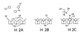
1つの態様において、反応容器のアレイは、マイクロウェルのアレイを密封要素と適合させることにより形成される。マイクロウェルは支持体材料の第1表面の小さな窪みである。マイクロウェルは、フォトリソグラフィ、スタンピング技術、成形技術およびマイクロエッチング技術などを含むがこれには限定されない種々の技術を用いて、当分野に一般に知られているように形成してよい。当業者が理解するように、用いる技術は、支持体材料の構成および形状に依存する。密封要素は、第1表面と同じトポロジーの第2表面を有し、これは第1表面と接触させられると、密封反応容器のアレイを作る。第1表面または第2表面のどちらかは、適合(compliant)材料から製造されて、密封を支援する。一方または両方の表面は、マイクロリアクターからの漏れを最小化するために、疎水性であるか、または疎水性領域を含む。 In one embodiment, the array of reaction vessels is formed by adapting the array of microwells with a sealing element. A microwell is a small depression in the first surface of the support material. The microwells may be formed as commonly known in the art using various techniques including, but not limited to, photolithography, stamping techniques, molding techniques, microetching techniques, and the like. As those skilled in the art will appreciate, the technique used depends on the configuration and shape of the support material. The sealing element has a second surface of the same topology as the first surface, which, when brought into contact with the first surface, creates an array of sealed reaction vessels. Either the first surface or the second surface is manufactured from a compliant material to aid sealing. One or both surfaces are hydrophobic or contain hydrophobic regions to minimize leakage from the microreactor.
他の態様において、反応容器のアレイは、離散的反応容積を分離するために閉じることができるチャネルおよびバルブを含む、マイクロ流体デバイスを用いて形成される。 In other embodiments, the array of reaction vessels is formed using a microfluidic device that includes channels and valves that can be closed to separate discrete reaction volumes.
1つの好ましい態様において、反応容器のアレイは、光ファイバー束の遠位端にマイクロウェルを作り、平面適合面を密封要素として利用して形成される。かかる反応容器のアレイは、次のようにして作製することができる。最初に、マイクロウェルのアレイを研磨した光ファイバー束の遠位端にエッチングする。光ファイバーの直径およびエッチングの深さを変えて、所望の容積のマイクロウェルを作製可能である。エッチング工程によって、マイクロウェルを束の中の個々のガラスファイバーのコア材料中に作製するが、ここで、各ウェルが1つのファイバーに同調され、隣接するウェルからは低速(slower)エッチングのクラッド材によって分離されているような様式で作製する。光ファイバーアレイ形式の1つの利点は、千個から百万個もの反応容器を、複雑なマイクロファブリケーション操作の必要なしに作製でき、多数の反応容器を同時に観察する能力を提供できることである。 In one preferred embodiment, the array of reaction vessels is formed using a microwell at the distal end of the fiber optic bundle and utilizing a planar conforming surface as a sealing element. Such an array of reaction vessels can be prepared as follows. First, an array of microwells is etched at the distal end of a polished optical fiber bundle. By changing the diameter of the optical fiber and the depth of etching, it is possible to produce microwells having a desired volume. The etching process creates microwells in the core material of individual glass fibers in a bundle, where each well is tuned to one fiber, and from adjacent wells, a slow-etch cladding material In a manner that is separated by One advantage of the fiber optic array format is that thousands to million reaction vessels can be made without the need for complex microfabrication operations, providing the ability to observe multiple reaction vessels simultaneously.
各マイクロウェルは束の中の光ファイバーに同調され、そのため光ファイバー束は、励起光および発光の両方を、ウェルへまたウェルから送達できて、ウェルの内容の遠隔調査が可能である。さらに、光ファイバーのアレイは、ファイバー間のシグナルの「クロストーク」なしで、隣接する容器中の分子を同時に励起する能力を提供する。すなわち、1つのファイバーに伝達された励起光は、隣接ファイバーに漏れ出すことはない。本発明の1つの側面において、米国特許第6,023,540号、第6,327.410号、および第6,858,394号における教示のようにして物理的代替案を作ることができ、これらの文献の各々は、本明細書にその全体が参照として組み込まれる。ガラスマイクロウェルの表面、密封要素の表面、または粒子のいずれかは、結合表面を作製するために官能化することができる。 Each microwell is tuned to an optical fiber in the bundle so that the optical fiber bundle can deliver both excitation light and emission to and from the well, allowing remote inspection of the contents of the well. In addition, an array of optical fibers provides the ability to simultaneously excite molecules in adjacent containers without “crosstalk” of signals between the fibers. That is, the excitation light transmitted to one fiber does not leak to the adjacent fiber. In one aspect of the invention, physical alternatives can be made as taught in US Pat. Nos. 6,023,540, 6,327.410, and 6,858,394, each of which is hereby incorporated by reference The whole is incorporated by reference. Either the surface of the glass microwell, the surface of the sealing element, or the particles can be functionalized to create a binding surface.
代替的に、等価な構造を、光ファイバー束の端を含まない他の方法を用いて製造することができる。例えばアレイは、当分野に知られたフォトリソグラフィ基板上にスポットするか印刷してもよく、例えば以下を参照のこと:WO 95/25116;WO 95/35505;PCT US98/09163;米国特許第5,700,637号;第5,807,522号;および第5,445,934号;およびU.S.S.N.s 08/851,203および09/187,289;これらの全ては参照として明示的に組み込まれる。 Alternatively, equivalent structures can be manufactured using other methods that do not include the ends of the fiber optic bundle. For example, the array may be spotted or printed on a photolithographic substrate known in the art, see for example: WO 95/25116; WO 95/35505; PCT US98 / 09163; US Pat. No. 5,700,637 No. 5,807,522; and 5,445,934; and USSNs 08 / 851,203 and 09 / 187,289, all of which are expressly incorporated by reference.
II.捕捉成分
本発明の実践中、反応容器内の結合表面(光ファイバー束に規定されたマイクロウェルを含む)は、少なくとも1つの捕捉成分を組み込む。捕捉成分(また一般に「捕捉結合リガンド」、「結合リガンド」、「捕捉結合種」、または「捕捉プローブ」としても言及される)は、分析物がアッセイの間固定されるように、固体支持体上に配置された分析物を、探る(probe)か、これに付着するか、結合するか、または他の方法でこれを捕捉するために用いることができる、任意の分子、化合物、または固体支持体修飾である。一般に捕捉成分は、検出、定量または他の分析目的のための、分析物の固体支持体(すなわち、マイクロウェル、密封要素またはナノ粒子の表面)への付着を可能にする。
II. Capture Component During practice of the invention, the binding surface within the reaction vessel (including the microwells defined in the fiber optic bundle) incorporates at least one capture component. The capture component (also commonly referred to as “capture binding ligand”, “binding ligand”, “capture binding species”, or “capture probe”) is a solid support so that the analyte is immobilized during the assay. Any molecule, compound, or solid support that can be used to probe, attach to, bind to, or otherwise capture the analyte disposed above Body modification. In general, the capture component allows attachment of the analyte to a solid support (ie, the surface of a microwell, sealing element or nanoparticle) for detection, quantification or other analytical purposes.
当業者が理解するように、捕捉成分の組成は分析物の組成に依存する。多様な分析物のための捕捉成分が公知であるか、または知られた技術を用いて容易に見出すことができる。例えば、分析物がタンパク質である場合、捕捉成分として、タンパク質(特に抗体またはそのフラグメント(FAbなど)を含む)、または小分子が挙げられる。好ましい捕捉成分タンパク質として、ペプチドが挙げられる。例えば、分析物が酵素である場合、好適な捕捉成分として、基質および阻害剤が挙げられる。抗原−抗体のペア、受容体−リガンド、ならびに炭水化物およびそれらの結合パートナーもまた、好適な分析物−捕捉成分のペアである。さらに、分析物が一本鎖核酸である場合、捕捉成分は、相補的な核酸であってもよい。同様に、分析物が核酸結合タンパク質であってもよく、捕捉成分は、一本鎖または二本鎖のいずれかの核酸である;あるいは、分析物が一本鎖または二本鎖の核酸である場合、捕捉成分は、核酸結合タンパク質であってもよい。あるいは、本明細書により援用される米国特許第5,270,163号、同第5,475,096号、同第5,567,588号、同第5,595,877号、同第5,637,459号、同第5,683,867号、同第5,705,337および関連特許において一般に記載されるように、ほぼ全ての分析物を捕捉するための、核酸「アプタマー」を開発してもよい。当業者が理解するように、会合する任意の2個の分子を、分析物としてまたは捕捉成分として用いることができる。同様に、分析物が炭水化物の場合、好適な捕捉成分としては、抗体およびレクチンが挙げられる。コンビナトリアル化学法に基づく捕捉成分の開発に関連する、広範な文献が存在することが理解される。 As those skilled in the art will appreciate, the composition of the capture component depends on the composition of the analyte. Capture components for a variety of analytes are known or can be readily found using known techniques. For example, when the analyte is a protein, the capture component can include a protein (particularly including an antibody or fragment thereof (such as a FAb)) or a small molecule. Preferable capture component proteins include peptides. For example, when the analyte is an enzyme, suitable capture components include substrates and inhibitors. Antigen-antibody pairs, receptor-ligands, and carbohydrates and their binding partners are also suitable analyte-capture component pairs. Further, when the analyte is a single stranded nucleic acid, the capture component may be a complementary nucleic acid. Similarly, the analyte may be a nucleic acid binding protein and the capture component is either a single stranded or double stranded nucleic acid; or the analyte is a single stranded or double stranded nucleic acid. In some cases, the capture component may be a nucleic acid binding protein. Or generally described in U.S. Pat. As such, nucleic acid “aptamers” may be developed to capture almost any analyte. As those skilled in the art will appreciate, any two molecules that associate can be used as an analyte or as a capture component. Similarly, when the analyte is a carbohydrate, suitable capture components include antibodies and lectins. It is understood that there is an extensive literature relating to the development of capture components based on combinatorial chemical methods.
好適な分析物/捕捉成分のペアとして、以下が挙げられるがこれらに限定されない:抗体/抗原、受容体/リガンド、タンパク質/核酸、酵素/基質および/または阻害剤、炭水化物(糖タンパク質および糖脂質を含む)/レクチン、タンパク質/タンパク質、タンパク質/小分子;ならびに、炭水化物およびそれらの結合パートナーもまた、好適な分析物−捕捉成分のペアである。これらは、野生型であっても誘導体の配列であってもよい。一態様によれば、捕捉成分は、成長ホルモン受容体、グルコーストランスポーター(特に、GLUT 4受容体)、およびT細胞受容体などの、多量体を形成することが知られている細胞表面受容体の部分(特に、細胞外部位)である。 Suitable analyte / capture component pairs include, but are not limited to: antibodies / antigens, receptors / ligands, proteins / nucleic acids, enzymes / substrates and / or inhibitors, carbohydrates (glycoproteins and glycolipids) ) / Lectins, proteins / proteins, proteins / small molecules; and carbohydrates and their binding partners are also suitable analyte-capture component pairs. These may be wild type or derivative sequences. According to one aspect, the capture component is a cell surface receptor known to form multimers, such as growth hormone receptors, glucose transporters (particularly GLUT 4 receptors), and T cell receptors. (Particularly the extracellular site).
好ましい態様において、捕捉成分は、「付着成分(attachment component)」(明細書中において「付着リンカー」としても言及される)を介して、結合表面(例えば、マイクロウェルの表面)に付着している。「付着成分」とは、本明細書において使用される場合、捕捉成分の付着をもたらす任意の成分、結合表面の官能化または修飾として定義され、結合剤(bond)および/またはリンカーを含み得る。あるいは、捕捉成分は、捕捉拡張成分(capture extender component)を利用することができる。この態様において、捕捉成分は、分析物に結合する第1の部分と、結合表面への付着のために用いることができる第2の部分を含む。 In preferred embodiments, the capture component is attached to a binding surface (eg, the surface of a microwell) via an “attachment component” (also referred to herein as an “attachment linker”). . An “attachment component” as used herein is defined as any component that results in attachment of a capture component, functionalization or modification of the binding surface, and may include a bond and / or a linker. Alternatively, the capture component can utilize a capture extender component. In this embodiment, the capture component includes a first portion that binds to the analyte and a second portion that can be used for attachment to the binding surface.
この付着成分はまた、例えば光ファイバー束のガラスなどの結合表面をアッセイ溶液から遮蔽する、保護層を提供することができる。その結果、付着成分は、アッセイおよび検出の間において、望ましくない蛍光ウェルおよび擬陽性シグナルを導く可能性のある、非標的分子の結合表面への非特異的付着を最小化する。 This attachment component can also provide a protective layer that shields the binding surface, eg, the glass of the fiber optic bundle, from the assay solution. As a result, the attachment component minimizes non-specific attachment of non-target molecules to the binding surface that can lead to undesirable fluorescent wells and false positive signals during assay and detection.
捕捉成分の付着成分への付着の方法は、一般に、当該分野において公知であるように行われ、付着成分および捕捉成分の組成に依存する。一般に、捕捉成分は、その後に付着のために用いることができる官能基の各々に対する使用を介して、付着成分に付着する。一態様によれば、官能基は化学官能基である。すなわち、結合表面を、化学官能基が結合表面に提示されるように誘導体化する。付着のための好ましい官能基は、アミノ基、カルボキシ基、エポキシド基、マレイミド基、オキソ基、およびチオール基である。これらの官能基を、直接的にまたはリンカーの使用を介して付着させることができ、その組合せは本明細書においてしばしば「クロスリンカー」として言及される。リンカーは、当該分野において公知である。例えば、ホモまたはヘテロ−二官能性リンカーなどが公知である(本明細書において参考として援用される1994 Pierce Chemical Company catalog, technical section on cross-linkers, pages 155-200を参照)。好ましいリンカーとして、以下が限定せずに挙げられる:短いアルキル基、エステル、アミド、アミンを有するアルキル基(置換アルキル基およびヘテロ原子部分を含有するアルキル基を含む)、エポキシ基、およびエチレングリコールおよび誘導体が好ましい。リンカーは、スルホンアミドを形成するスルホン基であってもよい。 The method of attachment of the capture component to the attachment component is generally performed as is known in the art and depends on the composition of the attachment component and the capture component. In general, the capture component attaches to the attachment component through use for each of the functional groups that can subsequently be used for attachment. According to one aspect, the functional group is a chemical functional group. That is, the binding surface is derivatized such that chemical functional groups are presented on the binding surface. Preferred functional groups for attachment are amino groups, carboxy groups, epoxide groups, maleimide groups, oxo groups, and thiol groups. These functional groups can be attached directly or through the use of a linker, the combination often referred to herein as a “crosslinker”. Linkers are known in the art. For example, homo- or hetero-bifunctional linkers are known (see 1994 Pierce Chemical Company catalog, technical section on cross-linkers, pages 155-200, incorporated herein by reference). Preferred linkers include, but are not limited to: short alkyl groups, esters, amides, alkyl groups with amines (including substituted alkyl groups and alkyl groups containing heteroatom moieties), epoxy groups, and ethylene glycol and Derivatives are preferred. The linker may be a sulfone group that forms a sulfonamide.
一態様によれば、官能基は、光によって活性化される官能基である。すなわち、光によって官能基を活性化し、捕捉成分または付着成分に付着させることができる。一例は、SurModics,Inc.(Eden Prairie、MN)から市販されるPhotoLink(登録商標)技術である。 According to one aspect, the functional group is a functional group that is activated by light. That is, the functional group can be activated by light and attached to the capture component or the attachment component. An example is SurModics, Inc. (Eden Prairie, MN). PhotoLink (registered trademark) technology commercially available.
代替的に、付着成分を、結合表面を共有結合的に修飾することなく添加する。すなわち、付着成分は、官能基と結合表面に対して結合親和性を有する基の両方を有する分子を用いて、結合表面に添加することができる。代替的に、付着成分は、結合表面に結合または固着することができる任意のタンパク質である。さらなる代替において、付着成分は、容器表面に結合または固着することができる任意の分子である。一例において、付着成分は、遊離アミン基を表面に有する血清アルブミンである。次いで、クロスリンカーを添加して、アルブミンのアミン基を捕捉成分に付着させることができる。 Alternatively, the attachment component is added without covalently modifying the binding surface. That is, the attachment component can be added to the binding surface using molecules having both functional groups and groups having binding affinity for the binding surface. Alternatively, the attachment component is any protein that can bind or adhere to the binding surface. In a further alternative, the attachment component is any molecule that can bind or adhere to the container surface. In one example, the attachment component is serum albumin having free amine groups on the surface. A crosslinker can then be added to attach the amine group of albumin to the capture component.
捕捉成分が化学的クロスリンカーである1つの態様によれば、分析物を、以下の様式において、化学的架橋を用いて結合表面上に捕捉する。第1に、結合表面を、アミン基などの官能基を用いて誘導体化する。次に、クロスリンカーの一端がアミン基に付着し、分析物がクロスリンカーの他の端に付着するにようにして、クロスリンカーおよび分析物を結合表面と接触させて配置する。以下により詳細に説明する分析物が酵素ではない一代替的態様において、酵素成分を有する標識を分析物に付着させてもよい。 According to one embodiment where the capture component is a chemical crosslinker, the analyte is captured on the binding surface using chemical cross-linking in the following manner. First, the binding surface is derivatized with a functional group such as an amine group. The crosslinker and the analyte are then placed in contact with the binding surface such that one end of the crosslinker is attached to the amine group and the analyte is attached to the other end of the crosslinker. In an alternative embodiment where the analyte described in more detail below is not an enzyme, a label having an enzyme component may be attached to the analyte.
この方法において、タンパク質、レクチン、核酸、有機小分子、炭水化物などを含む捕捉成分を添加してもよい。 In this method, capture components including proteins, lectins, nucleic acids, small organic molecules, carbohydrates and the like may be added.
一態様は、タンパク質性の捕捉成分を利用する。当該分野において公知であるように、タンパク質性捕捉成分を付着させるためにあらゆる数の技術を用いることができる。「タンパク質」は、この意味において、タンパク質、ポリペプチド、ペプチドを含み、例えば、酵素および抗体を含む。タンパク質に部分を追加するための多様な技術が知られている。1つの好ましい方法は、その全体が本明細書により参考として援用される米国特許第5,620,850号において概説される。表面へのタンパク質の付着は公知である;Heller, Ace. Chem. Res. 23:128 (1990)および関連文献も参照。 One embodiment utilizes a proteinaceous capture component. Any number of techniques can be used to attach the proteinaceous capture component, as is known in the art. “Protein” in this sense includes proteins, polypeptides, peptides and includes, for example, enzymes and antibodies. Various techniques are known for adding moieties to proteins. One preferred method is outlined in US Pat. No. 5,620,850, which is hereby incorporated by reference in its entirety. The attachment of proteins to the surface is known; see also Heller, Ace. Chem. Res. 23: 128 (1990) and related literature.
代替的な態様は、例えば、当該分野において周知であるように、分析物が核酸または核酸結合タンパク質である場合に関して、または、核酸がタンパク質に結合するためのアプタマーとして役立つ場合に関して、核酸を捕捉成分として用いる。 An alternative embodiment is, for example, as is well known in the art, for the case where the analyte is a nucleic acid or a nucleic acid binding protein, or for the case where the nucleic acid serves as an aptamer for binding to the protein. Used as
一態様によれば、各々の結合表面は、複数の捕捉成分分子を提示する。本発明の一側面において、複数の捕捉成分分子は、結合表面上に、「芝(lawn)」のように分配される。あるいは、捕捉成分は、任意の知られた様式において分配される。 According to one aspect, each binding surface presents a plurality of capture component molecules. In one aspect of the invention, the plurality of capture component molecules are distributed on the binding surface like a “lawn”. Alternatively, the capture component is dispensed in any known manner.
一態様によれば、捕捉成分と分析物との間の結合は特異的であり、捕捉成分は、結合ペアの一部である。すなわち、捕捉成分は、分析物に特異的に結合するか、または分析物に対する特異性を有する、標的特異的捕捉成分である。より具体的には、捕捉成分は、分析物に特異的かつ直接的に結合する。本明細書において、「特異的に結合する」または「結合特異性」により、捕捉成分が分析物に、分析物と試験サンプル中の他の成分または夾雑物との間を区別するために充分な特異性で結合することを意味する。例えば、一態様による捕捉成分は、分析物のある一部に特異的に結合する抗体である。一態様によれば、抗体は、分析物に特異的に結合することができる任意の抗体であってよい。例えば、好適な抗体として、以下が限定せずに挙げられる:モノクローナル抗体、二重特異性抗体、ミニボディー(minibody)、ドメイン抗体、合成抗体(しばしば「抗体模倣物(antibody mimetics)」として言及される)、キメラ抗体、ヒト化抗体、抗体融合物(しばしば「抗体複合体」として言及される)、および各々の断片。 According to one aspect, the binding between the capture component and the analyte is specific and the capture component is part of a binding pair. That is, the capture component is a target-specific capture component that specifically binds to the analyte or has specificity for the analyte. More specifically, the capture component binds specifically and directly to the analyte. As used herein, “specifically binds” or “binding specificity” means that the capture component is sufficient for the analyte to distinguish between the analyte and other components or contaminants in the test sample. It means to bind with specificity. For example, the capture component according to one embodiment is an antibody that specifically binds to a portion of the analyte. According to one aspect, the antibody may be any antibody capable of specifically binding to the analyte. For example, suitable antibodies include, but are not limited to: monoclonal antibodies, bispecific antibodies, minibodies, domain antibodies, synthetic antibodies (often referred to as “antibody mimetics”) ), Chimeric antibodies, humanized antibodies, antibody fusions (often referred to as “antibody complexes”), and fragments of each.
しかしながら、当業者に理解されるとおり、特異性が高くない結合を用いて分析物を検出することが可能である。例えば、システムは、例えば、異なる結合リガンドのパネルなどの異なる捕捉成分を用いてもよく、任意の特定の分析物の検出は、「電子鼻(electronic nose)」が作動する様式と同様に、その結合リガンドのパネルへの結合の「サイン(signature)」を介する。このことから、化学分析物の検出における特段の有用性を見出す。非特異的結合を除去する洗浄のステップを含むアッセイの条件下において結合したままでいるために、分析物と捕捉成分の間の親和性は充分であるべきである。一部の態様において、例えば特定の生体分子の検出において、分析物の捕捉成分への結合定数は、少なくとも約104〜106M−1であり、少なくとも約105〜109M−1であることが好ましく、少なくとも約107〜109M−1であることが特に好ましい。 However, as will be appreciated by those skilled in the art, it is possible to detect analytes using binding that is not highly specific. For example, the system may use different capture components, such as, for example, a panel of different binding ligands, and detection of any particular analyte will be similar to the manner in which the “electronic nose” operates. Via a “signature” of binding to a panel of binding ligands. This finds particular utility in the detection of chemical analytes. The affinity between the analyte and the capture component should be sufficient to remain bound under the conditions of the assay, including a wash step that removes non-specific binding. In some embodiments, for example in the detection of specific biomolecules, the binding constant of the analyte to the capture component is at least about 10 4 to 10 6 M −1 and at least about 10 5 to 10 9 M −1 . It is preferred that it is at least about 10 7 to 10 9 M −1 .
分析物が例えば細菌細胞を含む細胞である一態様によれば、捕捉成分はアドヘシン受容体分子であることができる。使用においては、アドヘシン受容体分子は、標的細胞の細胞外表面上のアドヘシンと称される表面タンパク質と結合することにより、細胞を固定または捕捉する。あるいは、細胞が別の型の細胞(非細菌細胞)である場合、捕捉成分は、分析物細胞に結合する好適な細胞表面受容体である。分析物が細胞であるさらなる態様において、捕捉成分はフィブロネクチンである。例えば、フィブロネクチンは、分析物が神経細胞である場合に用いることができる。 According to one embodiment, where the analyte is a cell including, for example, a bacterial cell, the capture component can be an adhesin receptor molecule. In use, an adhesin receptor molecule immobilizes or captures a cell by binding to a surface protein called an adhesin on the extracellular surface of the target cell. Alternatively, if the cell is another type of cell (non-bacterial cell), the capture component is a suitable cell surface receptor that binds to the analyte cell. In further embodiments in which the analyte is a cell, the capture component is fibronectin. For example, fibronectin can be used when the analyte is a nerve cell.
あるいは、捕捉成分は、非特異的な捕捉成分である。すなわち、捕捉成分は分析物に特異的に結合しないが、むしろ、分析物に会合するかまたは付着する、対応する結合パートナーに結合する。例えば、一態様による非特異的捕捉成分は、上記のような化学的クロスリンカーである。一態様によれば、分析物サンプル中の全てのペプチド分子が、化学的クロスリンカーに付着することができる。一態様による非特異的捕捉成分の例において、捕捉成分は、ストレプトアビジンである。ストレプトアビジンは、ビオチンに対して高い親和性で結合し、したがって、ビオチンが付着している任意の分子を捕捉する。あるいは、捕捉成分がビオチンであり、分析物がビオチンによって捕捉可能であるように、ストレプトアビジンが分析物に付着または会合している。 Alternatively, the capture component is a non-specific capture component. That is, the capture component does not specifically bind to the analyte, but rather binds to a corresponding binding partner that associates or attaches to the analyte. For example, the non-specific capture component according to one embodiment is a chemical crosslinker as described above. According to one aspect, all peptide molecules in the analyte sample can be attached to a chemical crosslinker. In an example of a non-specific capture component according to one aspect, the capture component is streptavidin. Streptavidin binds with high affinity to biotin and thus captures any molecule to which biotin is attached. Alternatively, streptavidin is attached to or associated with the analyte such that the capture component is biotin and the analyte can be captured by biotin.
一態様によれば、以下の様式において捕捉成分を結合表面に添加する。第1に、光ファイバー束の遠位端上のマイクロウェルのアレイを、捕捉成分(単数または複数)の付着のために準備する。すなわち、捕捉成分(単数または複数)がマイクロウェルの結合表面に付着するように、マイクロウェルの結合表面を修飾するか、またはマイクロウェルの結合表面に付着成分を添加する。一態様において、マイクロウェルの結合表面は、上記のように、化学官能性のもので誘導体化される。次いで、捕捉成分を添加する。 According to one embodiment, the capture component is added to the binding surface in the following manner. First, an array of microwells on the distal end of the fiber optic bundle is prepared for attachment of the capture component (s). That is, the binding surface of the microwell is modified such that the capture component (s) are attached to the binding surface of the microwell, or the attachment component is added to the binding surface of the microwell. In one embodiment, the binding surface of the microwell is derivatized with a chemical functionality as described above. The capture component is then added.
捕捉成分の付着の一例を図1に示す。ここで、本発明のマイクロウェルのアレイの結合表面は、ビオチンを用いて官能化される。図1aに示すとおり、この例における本発明のマイクロウェルのアレイは、光ファイバー束26の遠位端に形成される。捕捉成分を付着させるために、マイクロウェルの結合表面を、第1に、付着成分28により修飾する。付着成分28は、この例においては、図1bにおいて示すように、ファイバー束26の遠位端のコア30の表面とクラッド(cladding)32の表面との両方に結合するアミノプロピルシラン28である。NHS−ビオチンがアミノシラン化表面28に付着するので、アミノプロピルシランによる修飾は、この例において効果的である。しかしながら、捕捉成分はマイクロウェルの中にのみ存在すべきであるので、光ファイバー束の外部表面、例えばクラッド32の外部表面は、シラン化されるべきではない。すなわち、ビオチン付着を避けるために、外部クラッド表面32からシラン化を除去しなければならない。この例において、図1cに示すとおり、アミノシラン化光ファイバー束を10秒間0.3μmのラッピングフィルムで研磨し、それによりアミノシラン化されたクラッド層を除去することにより、シラン化28を外部クラッド層32から除去する。
An example of the attachment of the capture component is shown in FIG. Here, the binding surface of the array of microwells of the present invention is functionalized with biotin. As shown in FIG. 1 a, the array of microwells of the present invention in this example is formed at the distal end of the
付着成分28がマイクロウェルの結合表面に添加された後で、捕捉成分を付着させることができる。捕捉成分はビオチンであることができる。例えば図1dについて、ビオチンスクシンイミジルエステルは、マイクロウェル10の結合表面上のアミノ基28に付着する。
After the
マイクロウェル10内の捕捉成分の例を、図1e〜1gに示す。捕捉成分16は、任意のシール38を含んでよいマイクロウェル10の表面上に局在化してよく(図1e)、任意のシール38を含んでよいマイクロウェル10内に含まれる微粒子34上に局在化してよく(図1f)、および/または、マイクロウェル10のシール36上に局在化してよい(図1g)。
Examples of capture components within the
捕捉成分の付着の別の例を図9に示す。ここで、本発明のマイクロウェルの結合表面は、目的分析物に対する抗体を用いて官能化される。例3においてより詳細に説明される、図9に示すように、マイクロウェルのアレイは、光ファイバー束10の遠位端に形成される。抗体捕捉成分16を付着させるために、マイクロウェルの結合表面を最初に付着成分で修飾し、該付着成分は、例3においてはホモ二官能性クロスリンカーであるN,N’−ジスクシンイミジルカーボネートを用いて反応させた、アミノプロピルシランである。この表面を次に抗体上のリジン基と反応させて、マイクロウェルの結合表面において捕捉成分を提示させる。
Another example of the attachment of the capture component is shown in FIG. Here, the binding surface of the microwell of the present invention is functionalized with an antibody against the analyte of interest. As illustrated in FIG. 9 and described in more detail in Example 3, an array of microwells is formed at the distal end of the
III.分析物
本明細書において議論されるように、本発明の反応容器のアレイは、分析物の検出、定量、およびさらなる分析を提供する。本明細書における「分析物」または文法的に同等のものにより、検出されるかまたは評価されるべき任意の原子、分子、イオン、分子イオン、化合物、粒子、細胞、またはウイルスを意味する。
III. Analytes As discussed herein, the array of reaction vessels of the present invention provides for analyte detection, quantification, and further analysis. By “analyte” or grammatical equivalents herein is meant any atom, molecule, ion, molecular ion, compound, particle, cell, or virus that is to be detected or evaluated.
一態様によれば、分析物は酵素である。例えば、酵素は、次の酵素分類:酸化還元酵素、転移酵素、キナーゼ、加水分解酵素、リアーゼ、イソメラーゼおよびリガーゼ、のいずれかからの酵素であってよい。したがって、好適な酵素として以下が挙げられるがこれらに限定されない:ポリメラーゼ類、カテプシン類、カルパイン類、例えばASTおよびALTなどのアミノ転移酵素、例えばカスパーゼ類などのプロテアーゼ類、ヌクレオチドシクラーゼ類、転移酵素類、リパーゼ類、心臓発作に関連する酵素など。本発明のシステムをウイルスまたは細菌の標的物に用いる場合、好適な酵素は、ウイルスまたは細菌のポリメラーゼ類、ならびにウイルスまたは細菌のプロテアーゼ類を含む他のかかる酵素を含む。 According to one aspect, the analyte is an enzyme. For example, the enzyme may be an enzyme from any of the following enzyme classes: oxidoreductase, transferase, kinase, hydrolase, lyase, isomerase and ligase. Accordingly, suitable enzymes include, but are not limited to: polymerases, cathepsins, calpains, aminotransferases such as AST and ALT, proteases such as caspases, nucleotide cyclases, transferases Lipases, enzymes related to heart attacks, etc. When the system of the present invention is used for viral or bacterial targets, suitable enzymes include viral or bacterial polymerases, as well as other such enzymes including viral or bacterial proteases.
あるいは、分析物は、酵素成分を有する。例えば、分析物は、その細胞外表面上に存在する酵素または酵素成分を有する細胞であってもよい。あるいは、分析物は、その表面上に酵素成分を有さない細胞である。かかる細胞は、典型的には、「サンドイッチ」アッセイなどの以下に記載される間接的アッセイ方法を用いて同定される。 Alternatively, the analyte has an enzyme component. For example, the analyte may be a cell having an enzyme or enzyme component present on its extracellular surface. Alternatively, the analyte is a cell that does not have an enzyme component on its surface. Such cells are typically identified using indirect assay methods described below, such as a “sandwich” assay.
別の態様によれば、分析物は酵素ではない。当業者によって理解されるように、本発明において多数の分析物を用いることができる。基本的に、捕捉成分および/または二次結合リガンドに結合するあらゆる分析物を用いることができる。以下にさらに詳細に説明するように、これらの分析物は、典型的には、「サンドイッチ」アッセイなどの間接的なアッセイを用いて同定される。上記のように、1つの好適な分析物は細胞である。さらに、好適な分析物として、生体分子を含む有機および無機の分子が挙げられる。好ましい態様において、分析物は、タンパク質である。当業者によって理解されるとおり、本発明を用いて検出されるかまたは結合パートナーについて評価することができる多数の可能なタンパク質性分析物が存在する。上記のような酵素に加えて、好適なタンパク質分析物として、以下が挙げられるがこれらに限定されない:(1)免疫グロブリン;(2)ホルモンおよびサイトカイン(これらの多くは、細胞受容体に対するリガンドとして作用する);(3)癌マーカー;ならびに(4)他のタンパク質。 According to another aspect, the analyte is not an enzyme. As will be appreciated by those skilled in the art, a number of analytes can be used in the present invention. Essentially any analyte that binds to a capture component and / or a secondary binding ligand can be used. As described in more detail below, these analytes are typically identified using an indirect assay such as a “sandwich” assay. As noted above, one suitable analyte is a cell. Furthermore, suitable analytes include organic and inorganic molecules including biomolecules. In a preferred embodiment, the analyte is a protein. As will be appreciated by those skilled in the art, there are numerous possible proteinaceous analytes that can be detected using the present invention or evaluated for binding partners. In addition to enzymes as described above, suitable protein analytes include, but are not limited to: (1) immunoglobulins; (2) hormones and cytokines (many of these as ligands for cellular receptors) (3) cancer markers; and (4) other proteins.
分析物が酵素でなく、以下により詳細に記載するサンドイッチアッセイが行われる一態様によれば、以下により詳細に記載する酵素標識は、ベータガラクトシダーゼであってよい。あるいは、酵素標識は、アルカリホスファターゼまたはホースラディッシュペルオキシダーゼであってよいが、これらに限定されない。 According to one embodiment in which the analyte is not an enzyme and a sandwich assay, described in more detail below, is performed, the enzyme label described in more detail below may be beta galactosidase. Alternatively, the enzyme label can be, but is not limited to, alkaline phosphatase or horseradish peroxidase.
さらに、好適な分析物として、以下が挙げられるがこれらに限定されない:環境汚染物質(農薬、殺虫剤、毒素などを含む);化学物質(溶媒、ポリマー、有機物質などを含む);治療性分子(therapeutic molecule)(治療性および乱用薬物、抗生物質などを含む);生体分子(ホルモン、サイトカイン、タンパク質、核酸、脂質、炭水化物、細胞膜抗原、および受容体(神経、ホルモン、栄養因子、および細胞表面受容体)またはそれらのリガンドなど);全細胞(whole cell)(原核細胞(病原性細菌など)および真核細胞を含み、哺乳動物の腫瘍細胞を含む);ウイルス(レトロウイルス、ヘルペスウイルス、アデノウイルス、レンチウイルスなどを含む);ならびに胞子など。 In addition, suitable analytes include, but are not limited to: environmental pollutants (including pesticides, insecticides, toxins, etc.); chemicals (including solvents, polymers, organic substances, etc.); therapeutic molecules (Therapeutic molecule) (including therapeutic and abuse drugs, antibiotics, etc.); biomolecules (hormones, cytokines, proteins, nucleic acids, lipids, carbohydrates, cell membrane antigens, and receptors (nerves, hormones, trophic factors, and cell surfaces) Receptors) or their ligands); whole cells (including prokaryotic cells (such as pathogenic bacteria) and eukaryotic cells, including mammalian tumor cells); viruses (retroviruses, herpesviruses, adenos) Viruses, lentiviruses, etc.); as well as spores.
ある態様において、分析物は翻訳後修飾タンパク質(例えばリン酸化、メチル化、グリコシル化)であってよく、捕捉成分は、翻訳後修飾に特異的な抗体であってよい。修飾タンパク質は、複数の特異的抗体により捕捉され、次いで翻訳後修飾に特異的な二次抗体を用いて視覚化されることができる。代替的に、修飾タンパク質は翻訳後修飾に特異的な抗体により捕捉され、次いで各修飾タンパク質に特異的な抗体を用いて視覚化されてもよい。 In certain embodiments, the analyte can be a post-translationally modified protein (eg, phosphorylated, methylated, glycosylated) and the capture moiety can be an antibody specific for the post-translational modification. The modified protein can be captured by multiple specific antibodies and then visualized using a secondary antibody specific for post-translational modification. Alternatively, modified proteins may be captured by antibodies specific for post-translational modifications and then visualized using antibodies specific for each modified protein.
別の態様において、分析物は核酸である。核酸は、捕捉核酸(例えばオリゴヌクレオチド)により捕捉され、次いで別の特異的に標識されたオリゴヌクレオチドにより視覚化されることができる。 In another embodiment, the analyte is a nucleic acid. The nucleic acid can be captured by a capture nucleic acid (eg, an oligonucleotide) and then visualized by another specifically labeled oligonucleotide.
IV.検出可能な標識およびシグナル検出
種々の検出可能な標識が、本明細書に記載の方法の実践に使用可能であることが理解される。例えば、本発明の実践において、種々の着色標識(例えば金属ナノ粒子(例えば金ナノ粒子)、半導体ナノ粒子、半導体ナノ結晶(例えば量子ドット)、分光標識(例えば蛍光標識)、放射標識、および酵素標識を用いてよいことが理解される。
IV. Detectable Labels and Signal Detection It is understood that a variety of detectable labels can be used in the practice of the methods described herein. For example, in the practice of the present invention, various colored labels (eg, metal nanoparticles (eg, gold nanoparticles), semiconductor nanoparticles, semiconductor nanocrystals (eg, quantum dots), spectral labels (eg, fluorescent labels), radiolabels, and enzymes It will be appreciated that a label may be used.
特定のアッセイ形式に依存して、検出可能な標識を、捕捉成分に捕捉された後の分析物に、例えば、検出可能な標識に複合化されて捕捉分析物に結合する二次結合リガンドを介して、間接的に付着させる。標識が分析物に付着すると、標識の存在は、当分野に知られている、例えば光学検出器(例えば強化CCDカメラ)、蛍光検出器などの好適な検出システムを用いて、検出することができる。 Depending on the particular assay format, the detectable label is coupled to the analyte after it has been captured by the capture component, for example, via a secondary binding ligand that is conjugated to the detectable label and binds to the capture analyte. To attach indirectly. Once the label is attached to the analyte, the presence of the label can be detected using any suitable detection system known in the art, such as an optical detector (eg, an enhanced CCD camera), a fluorescence detector, etc. .
1つの態様において、標識は酵素標識である。この場合、発色、蛍光発生、または化学発光酵素基質を酵素に接触させて、検出可能産物を産生する。当分野では発色、蛍光発生、または化学発光酵素基質は知られており、または多くの異なる酵素について作製できることが理解される。したがって、特定酵素との反応で検出可能な標識を産生する、任意の既知の発色、蛍光発生、または化学発光酵素基質を、本発明において用いることができ、これにはThe Handbook--A Guide to Fluorescent Probes and Labeling Technologies, Tenth Ed, Chapter 10, http://probes.invitrogen.com/handbook/sections/1000.htmlに開示された任意の発色、蛍光発生、または化学発光酵素基質を含む;この文献は、本明細書にその全体が参照として組み込まれる。
In one embodiment, the label is an enzyme label. In this case, a chromogenic, fluorescent or chemiluminescent enzyme substrate is contacted with the enzyme to produce a detectable product. It is understood in the art that chromogenic, fluorogenic, or chemiluminescent enzyme substrates are known or can be made for many different enzymes. Thus, any known chromogenic, fluorogenic, or chemiluminescent enzyme substrate that produces a detectable label upon reaction with a particular enzyme can be used in the present invention, including the Handbook--A Guide to Fluorescent Probes and Labeling Technologies, Tenth Ed,
本明細書にさらに記載されるようにサンドイッチアッセイを用いて分析物を検出する、酵素標識がβ−ガラクトシダーゼである1つの態様によれば、アレイに添加される酵素基質は、レゾルフィン−β−Dガラクトピラノシドなどのβ−ガラクトシダーゼ基質である。 According to one embodiment in which the enzyme label is β-galactosidase, which detects an analyte using a sandwich assay as described further herein, the enzyme substrate added to the array is resorufin-β-D. A β-galactosidase substrate such as galactopyranoside.
V.アッセイ方法
本発明の反応容器のアレイは、いくつかの異なるアッセイ方法のために用いることができる。より具体的には、本発明は、(a)分析物の検出、および(b)サンプル中の分析物濃度の定量の両方を提供する。
V. Assay Methods The array of reaction vessels of the present invention can be used for several different assay methods. More specifically, the present invention provides both (a) detection of an analyte and (b) quantification of an analyte concentration in a sample.
一般に、本発明のマイクロウェルのアレイは、目的の分析物に暴露され(または、目的の分析物を含有するサンプルと接触させ)、分析物は、少なくとも1つの捕捉成分による分析物の捕捉に好適な条件、すなわち、一般的な生理学的条件下において、各マイクロウェル内で結合表面上の捕捉成分により捕捉される。本発明の用途を目的とする場合、用語「固定化」とは、結合表面上で捕捉成分に捕捉、付着、結合または付加(affix)されることを意味する。例えば、マイクロウェルを用いる状況において、任意の分析物分子とマイクロウェルの結合表面上の捕捉成分との間の相互作用は、そのマイクロウェル内での分析物分子の固定化をもたらす。 In general, the array of microwells of the present invention is exposed to an analyte of interest (or contacted with a sample containing the analyte of interest), and the analyte is suitable for capture of the analyte by at least one capture component. Under normal conditions, i.e. general physiological conditions, are captured by the capture component on the binding surface within each microwell. For purposes of the present invention, the term “immobilized” means captured, attached, bound or attached to a capture component on a binding surface. For example, in the context of using a microwell, the interaction between any analyte molecule and the capture component on the binding surface of the microwell results in the immobilization of the analyte molecule within that microwell.
本発明の一側面において、目的のサンプルを、分析物の濃度とサンプルの容積に応じて、約30分間〜約12時間の期間にわたり、本発明のマイクロウェルのアレイと接触させて配置する(または、マイクロウェルのアレイをサンプル中でインキュベートする)。1つの態様において、マイクロウェルのアレイとサンプルを、約50分間〜約70分間の期間にわたり接触させる。さらなる態様において、インキュベーションの期間は、約1時間である。 In one aspect of the invention, the sample of interest is placed in contact with the array of microwells of the invention (or for a period of about 30 minutes to about 12 hours, depending on the analyte concentration and sample volume) (or Incubate an array of microwells in the sample). In one embodiment, the array of microwells and the sample are contacted for a period of about 50 minutes to about 70 minutes. In a further embodiment, the incubation period is about 1 hour.
一態様によれば、マイクロウェルのアレイをサンプルに接触させた後に、洗浄のステップを行う。洗浄のステップは、捕捉成分に結合していないあらゆる分析物または非分析物分子を洗い流すことを目的とする。あるいは、洗浄のステップは必要でない。 According to one aspect, the washing step is performed after contacting the array of microwells with the sample. The washing step is intended to wash away any analyte or non-analyte molecules that are not bound to the capture component. Alternatively, no washing step is necessary.
本発明の一側面において、次いで、二次結合リガンドをマイクロウェルのアレイに添加する。一般に、二次結合リガンドを添加するのは、本明細書においてより詳細に記載されるように、分析物を検出する方法が「サンドイッチアッセイ」などの間接的アッセイである場合(分析物が酵素でない場合)である。上記のとおり、二次結合リガンドは、捕捉された分析物に会合するかまたは結合し、例えば酵素成分などの検出可能な標識を含む。二次結合リガンドは、二次結合リガンドがマイクロウェルのアレイの結合表面上の全ての結合した分析物と確実に接触するために充分な量で添加する。あるいは、例えば分析物が直接的に検出される場合、二次結合リガンドは添加しない。 In one aspect of the invention, a secondary binding ligand is then added to the array of microwells. In general, the secondary binding ligand is added when the method of detecting the analyte is an indirect assay such as a “sandwich assay” as described in more detail herein (the analyte is not an enzyme). If). As described above, the secondary binding ligand associates with or binds to the captured analyte and includes a detectable label, eg, an enzyme component. The secondary binding ligand is added in an amount sufficient to ensure that the secondary binding ligand is in contact with all bound analyte on the binding surface of the microwell array. Alternatively, no secondary binding ligand is added, for example when the analyte is detected directly.
着色標識および分光標識を用いる場合、標識は、適切な検出システムを用いて検出することができる。対照的に、標識が酵素標識の場合、酵素標識を発色、蛍光発生、または化学発光酵素基質と接触させて、検出可能産物を産生させる。 When using colored and spectroscopic labels, the label can be detected using an appropriate detection system. In contrast, when the label is an enzyme label, the enzyme label is contacted with a chromogenic, fluorogenic, or chemiluminescent enzyme substrate to produce a detectable product.
酵素標識の場合、次に上記の発色、蛍光発生、または化学発光酵素基質をマイクロウェルのアレイに導入または添加する。発色、蛍光発生、または化学発光酵素基質は、それ自体酵素である分析物、または例えば酵素標識抗体を介して酵素に結合した、任意の捕捉された分析物と接触するのに十分な量で、提供される。選択された酵素基質は、酵素成分と反応するか、または酵素成分により修飾され、このとき、該反応が発色、蛍光発生、または化学発光産物を産生し、したがって光学シグナルを産生するような様式において行われる。反応容器のアレイ中の発色、蛍光発生、または化学発光産物の存在は(以下に記載するように)、分析物と捕捉成分および酵素基質(および場合によっては二次結合リガンド)との相互作用に基づき、分析物の個性、および/またはその濃度についての情報を提供することができる。 In the case of enzyme labeling, the color development, fluorescence generation, or chemiluminescence enzyme substrate described above is then introduced or added to the array of microwells. The chromogenic, fluorogenic, or chemiluminescent enzyme substrate is in an amount sufficient to contact an analyte that is itself an enzyme, or any captured analyte that is bound to the enzyme, for example via an enzyme-labeled antibody, Provided. The selected enzyme substrate reacts with or is modified by the enzyme component, wherein the reaction produces a color, fluorescence, or chemiluminescent product, thus producing an optical signal. Done. Color development, fluorescence generation, or the presence of a chemiluminescent product in the array of reaction vessels (as described below) is responsible for the interaction of the analyte with the capture component and enzyme substrate (and possibly secondary binding ligand). Based on this, information about the individuality of the analyte and / or its concentration can be provided.
本発明の一態様において、酵素基質を添加して反応容器のアレイを形成した後に、マイクロウェルのアレイを密封する。すなわち、密封要素をマイクロウェルのアレイの面と接触させることにより、各々のマイクロウェルを流体的に分離し、その内容物を密封する。本明細書において「密封要素」とは、マイクロウェルのアレイ全体を覆うために充分に大きく、各々の反応容器の内容物が反応容器から漏出できないように各々の反応容器が密封されるかまたは分離されるようにマイクロウェルのアレイの外表面(例えば、光ファイバー束のクラッド)と接触することができる、任意の材料またはデバイスとして定義される。一態様によれば、密封要素は、シリコーンエラストマーのガスケットであって、基質の全体にわたって均一な圧力を伴ってマイクロウェルのアレイに対して配置される。各々のマイクロウェル中に内容物を密封することにより、酵素反応がこうして形成されたマイクロウェル中で進行することができ、それによって検出可能な量の発色、蛍光発生、または化学発光産物が産生され、それが反応容器中に検出の目的のために保持される。すなわち、酵素は基質を、発色、蛍光発生、または化学発光産物に変換し、これが各々の密封された反応容器中で局所的に高い濃度に蓄積し、検出可能な発色、蛍光発生、または化学発光性シグナルを生じる。 In one embodiment of the invention, the array of microwells is sealed after the enzyme substrate is added to form an array of reaction vessels. That is, by contacting the sealing element with the surface of the array of microwells, each microwell is fluidly separated and its contents sealed. As used herein, a “sealing element” is large enough to cover the entire array of microwells, and each reaction vessel is sealed or separated so that the contents of each reaction vessel cannot leak from the reaction vessel. As defined as any material or device that can contact the outer surface of an array of microwells (eg, the cladding of a fiber optic bundle). According to one aspect, the sealing element is a silicone elastomer gasket that is placed against the array of microwells with a uniform pressure across the substrate. By sealing the contents in each microwell, the enzymatic reaction can proceed in the microwell thus formed, thereby producing a detectable amount of color development, fluorescence generation, or chemiluminescent product. It is retained in the reaction vessel for detection purposes. That is, the enzyme converts the substrate into a chromogenic, fluorogenic, or chemiluminescent product that accumulates locally at high concentrations in each sealed reaction vessel and can detect chromogenic, fluorogenic, or chemiluminescent Produces sex signals.
一態様によれば、本発明は、密封要素を適用する機械的なプラットフォームを備えた顕微鏡システムを提供する。プラットフォームは、顕微鏡のステージの下で、顕微鏡システム上に配置される。酵素基質をマイクロウェルのアレイに添加した後、密封要素を、機械的プラットフォームにより適用される均一な圧力を用いて、平らな表面(例えば、顕微鏡スライドグラス)とマイクロウェルのアレイとの間にサンドイッチする。 According to one aspect, the present invention provides a microscope system with a mechanical platform that applies a sealing element. The platform is placed on the microscope system under the microscope stage. After the enzyme substrate is added to the microwell array, the sealing element is sandwiched between a flat surface (eg, a microscope slide) and the microwell array using the uniform pressure applied by the mechanical platform. To do.
分析物を検出するためのアッセイは、当業者に理解されるように、多様な実験条件下において行うことができる。多様な他の試薬をスクリーニングアッセイにおいて含めることができる。これらは、塩、中性タンパク質、例えばアルブミン、洗剤などの試薬を含み、これらは、最適なタンパク質−タンパク質結合を促進するため、および/または非特異的もしくはバックグラウンドの相互作用を低減するために用いることができる。また、その他にアッセイの効率を改善する試薬、例えばプロテアーゼ阻害剤、ヌクレアーゼ阻害剤、抗菌剤などを用いてもよい。成分の混合物は、必要な結合を提供する任意の順序で添加することができる。当該分野において公知であるように、多様なブロッキングおよび洗浄のステップを利用することができる。 Assays for detecting analytes can be performed under a variety of experimental conditions, as will be appreciated by those skilled in the art. A variety of other reagents can be included in the screening assay. These include reagents such as salts, neutral proteins such as albumin, detergents, etc., to promote optimal protein-protein binding and / or to reduce non-specific or background interactions Can be used. In addition, reagents that improve the efficiency of the assay, such as protease inhibitors, nuclease inhibitors, antibacterial agents, and the like, may be used. The mixture of components can be added in any order that provides the requisite binding. A variety of blocking and washing steps can be utilized, as is known in the art.
酵素活性またはその光学的特性の変化を示す反応容器を、従来の光列(optical train)および光学検出システムにより同定することができる。用いられる特定の酵素基質およびそれらの産物の作動波長に依存して、特定の波長のために設計された光学フィルターを、反応容器の光学調査のために用いることができる。好ましい態様において、本発明の反応容器のアレイは、光ファイバー束の一部として直接形成される。 Reaction vessels that exhibit a change in enzyme activity or its optical properties can be identified by conventional optical trains and optical detection systems. Depending on the specific enzyme substrates used and the operating wavelengths of their products, optical filters designed for specific wavelengths can be used for optical investigation of reaction vessels. In a preferred embodiment, the array of reaction vessels of the present invention is formed directly as part of an optical fiber bundle.
一態様によれば、本発明の反応容器のアレイは、その全体が本明細書において参考として援用される米国特許出願第09/816,651号において記載されるシステムのような光学検出システムと組み合わせて用いてもよい。例えば、一態様によれば、本発明の反応容器のアレイは、光ファイバーの集合の遠位端であって、クラッドファイバーから構成される光ファイバー束を含み、したがって、光はファイバー間で混じらない。09/816,651出願において示されるように、束の近位端は、z−翻訳ステージおよびx−yマイクロポジショナーにより受容される。 According to one aspect, the array of reaction vessels of the present invention is used in combination with an optical detection system such as the system described in US patent application Ser. No. 09 / 816,651, which is incorporated by reference herein in its entirety. May be. For example, according to one aspect, the array of reaction vessels of the present invention includes a fiber optic bundle composed of clad fibers at the distal end of a collection of optical fibers, so that light does not mix between the fibers. As shown in the 09 / 816,651 application, the proximal end of the bundle is received by a z-translation stage and an xy micropositioner.
米国特許出願第09/816,651号の光学検出システムは、以下のように作動する。光ファイバー束の遠位端から戻る光はアタッチメントを通って倍率交換装置(magnification changer)に入り、該倍率交換装置は、ファイバーの近位または遠位端の画像サイズの調整を可能にする。倍率交換装置を通過する光は、次いで、第2ホイールによりシャッターを閉めてフィルタリングされる。光は、次いで、電荷結合素子(CCD)カメラで画像化される。コンピューターが画像処理ソフトウェアを実行してCCDカメラからの情報を処理し、また、可能であれば第1および第2のシャッターおよびフィルターホイールを制御する。 The optical detection system of US patent application Ser. No. 09 / 816,651 operates as follows. Light returning from the distal end of the fiber optic bundle enters the magnification changer through the attachment, which allows adjustment of the image size of the proximal or distal end of the fiber. The light passing through the magnification changer is then filtered with the second wheel closing the shutter. The light is then imaged with a charge coupled device (CCD) camera. A computer executes image processing software to process information from the CCD camera and, if possible, controls the first and second shutters and the filter wheel.
本発明の反応容器のアレイは、多様な適合する方法を用いて、光ファイバー束の遠位端に一体化するか、またはこれに取り付けることができる。光ファイバー束の各個々のファイバーの中心にマイクロウェルを形成し、反応容器は、このマイクロウェルのアレイを密封要素で密封することにより形成される。したがって、光ファイバー束の各々の光ファイバーが、そのファイバーの遠位端の中心に形成された1つのマイクロウェルからの光を運搬する。この特徴は、個々の反応容器の光学的特性の調査を可能とし、各々のマイクロウェル中の反応物を同定するために必要である。したがって、束の末端をCCDアレイ上に画像化することにより、反応容器の光学的特性を個々に調査することができる。 The array of reaction vessels of the present invention can be integrated or attached to the distal end of a fiber optic bundle using a variety of compatible methods. A microwell is formed in the center of each individual fiber of the fiber optic bundle, and the reaction vessel is formed by sealing this array of microwells with a sealing element. Thus, each optical fiber of the optical fiber bundle carries light from one microwell formed at the center of the distal end of the fiber. This feature allows the investigation of the optical properties of individual reaction vessels and is necessary to identify the reactants in each microwell. Therefore, the optical properties of the reaction vessel can be individually investigated by imaging the ends of the bundle on a CCD array.
A.検出
前に記載したように、検出システムは検出される標識に依存する。例えば、標識が光学標識、分光標識または放射標識の場合、標識の存在は当分野に知られている市販の検出器を用いて決定することができる。
A. As described before detection , the detection system depends on the label to be detected. For example, if the label is an optical label, a spectroscopic label or a radiolabel, the presence of the label can be determined using commercially available detectors known in the art.
標識が酵素標識の場合、標識は直接的に(例えば、分析物が固有の酵素活性を持つ場合)、または間接的に(例えば、分析物が酵素活性を示さない場合)、当分野に知られた技術を介して検出することができる。言い換えれば、分析物が酵素であれば、分析物は直接的検出法により同定することができる。代替的に、標的分析物が酵素ではなく、したがって酵素基質の存在下において発色、蛍光発生、または化学発光産物を産生できない場合、分析物は間接的検出法により同定される。 Where the label is an enzyme label, the label is known in the art either directly (eg, when the analyte has intrinsic enzyme activity) or indirectly (eg, when the analyte does not exhibit enzyme activity). Can be detected through different techniques. In other words, if the analyte is an enzyme, the analyte can be identified by a direct detection method. Alternatively, if the target analyte is not an enzyme and therefore cannot produce color, fluorescence, or chemiluminescent products in the presence of the enzyme substrate, the analyte is identified by an indirect detection method.
酵素である分析物に関する直接的検出法は、次のように進行する。第1に、目的のサンプルとマイクロウェルのアレイとを、上記でより詳細に記載したように、好適な条件下において接触させる。酵素基質を、サンプルと同時に、またはサンプルの添加後に、添加する。 A direct detection method for an analyte that is an enzyme proceeds as follows. First, the sample of interest and the array of microwells are contacted under suitable conditions, as described in more detail above. The enzyme substrate is added at the same time as the sample or after the sample is added.
マイクロウェルを密封した後、任意の所与の反応容器中の分析物の存在または不在を、次いで光学的調査により検出する。すなわち、発色、蛍光発生、または化学発光産物の産生によって引き起こされる光学的シグナルのあらゆる変化を検出する。分析物を含有する任意の反応容器中で、分析物は、何らかの方法で酵素基質を修飾するかまたは酵素基質に作用し、それにより発色、蛍光発生、または化学発光産物の放出をもたらし、該反応容器からの光学シグナルの変化を生じる。次いで、発色、蛍光発生、または化学発光産物を、光学的に検出する。 After sealing the microwell, the presence or absence of the analyte in any given reaction vessel is then detected by optical inspection. That is, any change in the optical signal caused by color development, fluorescence generation, or production of a chemiluminescent product is detected. In any reaction vessel containing the analyte, the analyte modifies or acts on the enzyme substrate in some way, thereby resulting in color development, fluorescence generation, or release of a chemiluminescent product. This produces a change in the optical signal from the container. Color development, fluorescence generation, or chemiluminescent products are then detected optically.
本発明の一態様において、上記のように、マイクロウェルのアレイは、酵素基質の添加後に密封要素により密封されて、反応容器を形成する。 In one embodiment of the invention, as described above, the array of microwells is sealed with a sealing element after addition of the enzyme substrate to form a reaction vessel.
間接的検出法は、酵素特性を有さない分析物に関する。本発明と共に用いることができる2つの間接的方法は、「サンドイッチ」アッセイおよび「競合的」アッセイである。標識が光学標識、分光標識および放射標識の場合、類似のアッセイ方式を使用可能であることが意図される。 Indirect detection methods relate to analytes that do not have enzymatic properties. Two indirect methods that can be used with the present invention are the “sandwich” assay and the “competitive” assay. It is contemplated that similar assay formats can be used where the label is an optical label, a spectroscopic label and a radiolabel.
サンドイッチアッセイは、図2に示すように行うことができる。第1に、目的のサンプルとマイクロウェルのアレイ10とを、図2aに示すように、および上記により詳細に記載するように接触させる。好適な条件下において、サンプル中に存在する分析物12は、図2bに示すように、マイクロウェル14の結合表面上に提示された捕捉成分16によって捕捉される。一態様によれば、次いで洗浄のステップを行う。
The sandwich assay can be performed as shown in FIG. First, the sample of interest and the array of
次に、図2cに示すように、「二次結合リガンド」18をマイクロウェルのアレイ10に添加する。二次結合リガンド18は、分析物12に結合する点において捕捉成分16と類似する。二次結合リガンド18は、捕捉成分16と同一であっても異なっていてもよい。捕捉された分析物12に対する二次結合リガンド18の結合は、ある種の「サンドイッチ」を形成する。分析物が不在の場合、二次結合リガンド18は洗い流される。
Next, as shown in FIG. 2 c, “secondary binding ligand” 18 is added to the
二次結合リガンド18は、結合成分22および酵素標識または酵素を捕捉可能な標識24の、2つの成分を有する。結合成分22は、分析物12に結合する二次結合リガンド18の一部分である。典型的には、二次結合リガンド18は、捕捉成分16とは異なる、分析物12の部分に結合する。なぜならば、捕捉成分16と二次結合リガンド18との両方が同一の部分に結合する場合、二次結合リガンド18は、捕捉された分析物12には結合することができないからである。したがって、選択された二次結合リガンド18は、分析物12が捕捉成分16を介して結合表面14に結合した状態で、分析物12に結合することができる。
The secondary
標識24は、酵素活性を奏するか、または続いて酵素を捕捉するために用いることのできる、二次結合リガンド18の部分である。一態様によれば、標識24は、二次結合リガンド18に付着した酵素である。
The
その後、酵素基質を添加する。本発明の一態様において、上記のように酵素基質が添加された後に、マイクロウェルのアレイを密封し、反応容器を形成する。次いで、任意の所与の反応容器中の分析物の存在または不在を、光学的調査によって検出する。すなわち、発色、蛍光発生、または化学発光産物の産生によって引き起こされる光学的シグナルのあらゆる変化が検出される。分析物および二次結合リガンドを含有する任意の反応容器中で、二次結合リガンドに会合した酵素は、何らかの方法で酵素基質を修飾するかまたは酵素基質に作用し、それにより発色、蛍光発生、または化学発光産物を産生し、該反応容器からの光学シグナルの変化を生じる。次いで、産物を光学的に検出する。 Thereafter, the enzyme substrate is added. In one embodiment of the invention, after the enzyme substrate is added as described above, the array of microwells is sealed to form a reaction vessel. The presence or absence of the analyte in any given reaction vessel is then detected by optical inspection. That is, any change in the optical signal caused by color development, fluorescence generation, or production of a chemiluminescent product is detected. In any reaction vessel containing the analyte and the secondary binding ligand, the enzyme associated with the secondary binding ligand modifies the enzyme substrate or acts on the enzyme substrate in some way, thereby producing color, fluorescence generation, Or a chemiluminescent product is produced, resulting in a change in the optical signal from the reaction vessel. The product is then detected optically.
競合的アッセイは以下のように操作される。第1に、標識された分子を本発明のマイクロウェルのアレイに添加する。ここで、標識は、酵素または酵素成分である。この態様において、選択された標識分子は、標識分子のアレイへの添加がマイクロウェルの結合表面上の捕捉成分への標識分子の結合をもたらすように、捕捉成分に結合する。 The competitive assay is operated as follows. First, a labeled molecule is added to the array of microwells of the present invention. Here, the label is an enzyme or an enzyme component. In this embodiment, the selected label molecule binds to the capture component such that addition of the label molecule to the array results in binding of the label molecule to the capture component on the binding surface of the microwell.
次いで、目的のサンプルとマイクロウェルのアレイとを、上でより詳細に記載したように接触させる。マイクロウェルのアレイ中の分析物の存在は、標識された分子の移動(displacement)、および分析物の捕捉成分への結合を引き起こす。移動は、以下の理由により起こる:この態様において、選択された捕捉成分は、標識された分子または分析物のいずれかに結合することができ、したがって、競合的結合状態をもたらす。その結果、標識された分子がマイクロウェルの結合表面上の捕捉成分に結合しており、分析物が添加される場合、分析物は、好適な条件下において標識された分子を移動させる。 The sample of interest and the array of microwells are then contacted as described in more detail above. The presence of the analyte in the array of microwells causes displacement of the labeled molecule and binding of the analyte to the capture component. Migration occurs for the following reasons: In this embodiment, the selected capture component can bind to either the labeled molecule or the analyte, thus resulting in a competitive binding state. As a result, when the labeled molecule is bound to a capture component on the binding surface of the microwell and the analyte is added, the analyte moves the labeled molecule under suitable conditions.
一態様によれば、次いで、あらゆる非結合の標識された分子をマイクロウェルのアレイの結合表面から除去するために、洗浄のステップを行う。 According to one aspect, a washing step is then performed to remove any unbound labeled molecules from the binding surface of the array of microwells.
その後、酵素基質を添加する。そして、上記のように、本発明の一側面によれば、酵素基質を添加した後にマイクロウェルのアレイを密封して、反応容器を形成する。あるいは、マイクロウェルのアレイは密封しない。次に、任意の所与の反応容器中の分析物の存在または不在を、光学的調査により検出する。しかし、上記の光学的調査とは異なり、この調査においては、発色、蛍光発生、または化学発光産物を欠いていることが、反応容器中の分析物の存在を示す。分析物を含有する任意の反応容器において酵素反応は起こらず、該反応容器からの光学的シグナルの変化は起こらない。対照的に、標識された分子が未だ存在する任意の反応容器において、光学的シグナルが検出される。 Thereafter, the enzyme substrate is added. And, as described above, according to one aspect of the invention, after adding the enzyme substrate, the array of microwells is sealed to form a reaction vessel. Alternatively, the microwell array is not sealed. The presence or absence of the analyte in any given reaction vessel is then detected by optical inspection. However, unlike the optical investigation described above, the lack of color development, fluorescence generation, or chemiluminescence products in this investigation indicates the presence of the analyte in the reaction vessel. There is no enzymatic reaction in any reaction vessel containing the analyte and no change in the optical signal from the reaction vessel. In contrast, an optical signal is detected in any reaction vessel where labeled molecules are still present.
競合的アッセイの態様の代替的バージョンにおいて、標識された分子および目的のサンプルの両方をマイクロウェルのアレイに同時に決まった容積で添加する。このバージョンにおいて、分析物および標識された分子は、捕捉成分の結合部位について直接的に競合する。 In an alternative version of the competitive assay embodiment, both the labeled molecule and the sample of interest are added simultaneously to a microwell array in a fixed volume. In this version, the analyte and the labeled molecule compete directly for the binding site of the capture component.
さらに、本明細書に記載された方法および組成物は、多様な多重アッセイにおいて、サンプル中の1または2種以上の分析物の存在を検出するために使用可能であることが理解される。例示の多重アッセイについては、以下の節に記載する。 It is further understood that the methods and compositions described herein can be used to detect the presence of one or more analytes in a sample in a variety of multiplex assays. Exemplary multiplex assays are described in the following sections.
1.同一の標的分析物に対する多数の異なる捕捉成分
一態様による本発明の反応容器アレイは、単一の標的分析物に指向するが同一ではない複数の捕捉成分を利用する。すなわち、複数の結合成分は、分析物の異なる結合部位に結合する。したがってこの態様は、1より多くの異なる捕捉成分を各々の結合表面上に、または異なる捕捉成分を異なる結合表面上に提供する。一例において、1つの分析物を、2または3以上の捕捉成分であって、各々が分析物の異なる部位に結合可能である前記捕捉成分により、調査する。このことにより、非特異的結合相互作用が統計的に最少化されるので、信頼度が高まる。この態様において、タンパク質性分析物を評価する場合、好ましい態様は、標的の異なる部分に結合する捕捉成分を利用する。例えば、同一の分析物タンパク質の異なる部分に対する2または3以上の抗体(または抗体フラグメント)を捕捉成分として使用する場合、好ましい態様は、異なるエピトープに対する抗体を利用する。同様に、核酸分析物を評価する場合、余剰の核酸プローブは、オーバーラップしているか、隣接しているか、または空間的に分離していてよい。しかしながら、2つのプローブが単一の結合部位について競合しないことが好ましく、したがって、隣接しているか分離しているプローブが好ましい。
1. Numerous different capture components for the same target analyte The reaction vessel array of the present invention according to one embodiment utilizes multiple capture components directed to a single target analyte but not identical. That is, the plurality of binding components bind to different binding sites on the analyte. This embodiment thus provides more than one different capture component on each binding surface or different capture components on different binding surfaces. In one example, an analyte is investigated with two or more capture components, each of which is capable of binding to a different site of the analyte. This increases reliability because non-specific binding interactions are statistically minimized. In this embodiment, when assessing proteinaceous analytes, a preferred embodiment utilizes capture components that bind to different portions of the target. For example, when two or more antibodies (or antibody fragments) against different portions of the same analyte protein are used as capture components, preferred embodiments utilize antibodies against different epitopes. Similarly, when evaluating nucleic acid analytes, excess nucleic acid probes may overlap, be contiguous, or be spatially separated. However, it is preferred that the two probes do not compete for a single binding site, and therefore adjacent or separate probes are preferred.
この態様において、複数の異なる捕捉成分を用いてもよく、約2〜約20が好ましく、約2〜約10がより好ましく、および2〜約5が特に好ましく、これは、2、3、4または5を含む。しかしながら、上記のように、用途に依存して、より多くを用いてもよい。 In this embodiment, a plurality of different capture components may be used, preferably from about 2 to about 20, more preferably from about 2 to about 10, and particularly preferably from 2 to about 5, which is 2, 3, 4 or 5 is included. However, as described above, more may be used depending on the application.
2.複数の標的分析物に対する複数の異なる捕捉成分
別の態様によれば、本発明の反応容器アレイは、同一でも異なっていてもよい複数の標的分析物に指向された、複数の異なる捕捉成分を利用する。この態様は、各々の結合表面上の1より多くの異なる捕捉成分、または異なる結合表面上の異なる捕捉成分を含む。一例において、同一の結合表面または異なる結合表面上の2または3以上の捕捉成分が結合することができる、2または3以上の分析物を提供してもよい。
2. Multiple different capture components for multiple target analytes According to another aspect, the reaction vessel array of the present invention utilizes multiple different capture components directed to multiple target analytes that may be the same or different. To do. This embodiment includes more than one different capture component on each binding surface, or different capture components on different binding surfaces. In one example, two or more analytes may be provided to which two or more capture components on the same binding surface or different binding surfaces can bind.
この態様において、1より多くの標的分析物を同定することができる。例えば、直接アッセイの場合は各々の異なる分析物が異なる酵素であるか、または間接アッセイの場合は各々の標的が異なる標識と複合化された結合部分に結合する限り、2または3以上の標的分析物を同定することができる。一態様において、分析物は、複数の酵素基質を用いて同定され、ここで、各々の基質は、適切な酵素との相互作用の際に異なる色を生じる。したがって、各々の標的分析物は、酵素基質との反応により生じた色に基づいて区別することができる。酵素以外の標識を用いる場合、異なる標識は異なる特性を有するべきであり、これにより各々の異なる標識が、適切な検出器により同定可能である。 In this aspect, more than one target analyte can be identified. For example, two or more target assays as long as each different analyte is a different enzyme in the case of a direct assay or each target binds to a binding moiety complexed with a different label in the case of an indirect assay. Things can be identified. In one embodiment, the analyte is identified using multiple enzyme substrates, wherein each substrate produces a different color upon interaction with the appropriate enzyme. Thus, each target analyte can be distinguished based on the color produced by reaction with the enzyme substrate. When using labels other than enzymes, the different labels should have different properties so that each different label can be identified by a suitable detector.
逐次アプローチと呼ばれる代替的アプローチにおいて、分析物は、同一または異なる標識を用いて同定される。このアプローチにおいて、1または2以上の目的分析物は、1または2以上の結合表面上に捕捉される。次に、分析物に結合する第1標識結合部分を、第1固定化分析物に結合させる。標識の存在は、適切な検出システムにより検出可能である。その後、第1標識結合部分を、例えば洗浄により除去する。次に、第2の異なる分析物に結合する、第2標識結合部分を、第2分析物に結合させる。標識の存在は、適切な検出システムにより検出可能である。その後、第2標識結合部分は、洗浄により除去することができ、このプロセスは所望のように繰り返すことができる。このアプローチにおいては、同一または異なる標識が、第1および第2標識結合部分に存在可能であることが理解される。本明細書に記載された全ての標識を、このアプローチに使用可能であることが理解される。標識が酵素の場合、逐次反応は、各々が同一または異なる色を生じる基質を用いて実施可能であることが理解される。 In an alternative approach, called the sequential approach, analytes are identified using the same or different labels. In this approach, one or more target analytes are captured on one or more binding surfaces. Next, a first labeled binding moiety that binds to the analyte is bound to the first immobilized analyte. The presence of the label can be detected by a suitable detection system. Thereafter, the first label binding moiety is removed, for example, by washing. A second labeled binding moiety that binds to a second different analyte is then bound to the second analyte. The presence of the label can be detected by a suitable detection system. The second label binding moiety can then be removed by washing and the process can be repeated as desired. In this approach, it is understood that the same or different labels can be present on the first and second label binding moieties. It is understood that all labels described herein can be used for this approach. When the label is an enzyme, it is understood that sequential reactions can be performed with substrates that each produce the same or different color.
この態様において、複数の異なる捕捉成分を用いることができ、約2〜約100が好ましく、約2〜約20がさらに好ましく、および2〜約10が特に好ましく、これは、2、3、4または5、6、7、8、9を含む。しかしながら、上記のように、用途に依存してより多くを用いてもよい。 In this embodiment, a plurality of different capture components can be used, preferably from about 2 to about 100, more preferably from about 2 to about 20, and particularly preferably from 2 to about 10, which is 2, 3, 4 or 5, 6, 7, 8, 9 included. However, as described above, more may be used depending on the application.
空間的(spatial)アプローチと呼ばれる他のアプローチにおいて、(i)結合表面の別の領域内に配置された2つの異なる捕捉成分、(ii)結合表面の別の領域に適用された、2つの異なる標識結合部分、または(iii)(i)と(ii)の組合せ、のいずれかを用いることも可能である。 In another approach, referred to as a spatial approach, (i) two different capture components located within another region of the binding surface, (ii) two different applied to another region of the binding surface Either a label binding moiety or a combination of (iii) (i) and (ii) can be used.
空間的アプローチの第1例において、異なる捕捉成分を結合表面の別の領域に適用する。例えば、これは、ファイバーマイクロアレイが結合表面として用いられる場合にはファイバーマイクロアレイの異なる領域上に、または密封要素が結合表面として用いられる場合は密封要素に、微液滴を配置することにより、実現することができる。各々の微液滴は異なる捕捉成分を含有し、これは表面を、異なる捕捉成分と接触することにより官能化する。この方法により、液滴の大きさに依存して、空間的に離れた結合表面上に異なる捕捉成分のアレイを作製することが可能である。この様式で検出可能な多重分析物の数は、異なる捕捉成分領域のサイズおよび、反応容器のアレイのサイズに依存する。 In a first example of a spatial approach, different capture components are applied to different areas of the binding surface. For example, this can be achieved by placing microdroplets on different regions of the fiber microarray if the fiber microarray is used as a binding surface, or on the sealing element if a sealing element is used as the binding surface. be able to. Each microdroplet contains a different capture component, which functionalizes the surface by contacting it with a different capture component. This method makes it possible to produce an array of different capture components on spatially separated binding surfaces, depending on the droplet size. The number of multiple analytes detectable in this manner depends on the size of the different capture component regions and the size of the array of reaction vessels.
空間的アプローチの第2の例において、目的分析物は、結合表面にわたり、または結合表面の分離された領域内で、均一に捕捉することができる。しかしこのアプローチにおいて、第1標識結合部分を結合表面の第1領域に適用して、第1分析物の存在を検出する。同時に、または順次に、第2標識結合部分を結合表面の第2領域に適用して、第2分析物の存在を検出する。 In a second example of a spatial approach, the analyte of interest can be captured uniformly across the binding surface or within a separated region of the binding surface. However, in this approach, a first labeled binding moiety is applied to the first region of the binding surface to detect the presence of the first analyte. Simultaneously or sequentially, a second labeled binding moiety is applied to the second region of the binding surface to detect the presence of the second analyte.
異なる分析物を指向する捕捉成分および同一分析物を指向する複数の捕捉成分を含む、上記の異なるアッセイ形態の各々は、以下に記載するように、定量についても利用可能であることが理解される。 It is understood that each of the above different assay formats, including capture components directed to different analytes and multiple capture components directed to the same analyte, can also be used for quantification, as described below. .
さらに、一定の状況下で、順次アッセイの間にマイクロウェルのアレイを再利用可能であることが理解される。このアプローチにおいては、第1アッセイにおいて分析物を含有するウェルのログを記録し、次に、続くアッセイにおいて、前に分析物を含有したウェルを、次のアッセイで用いるマイクロウェルのアッセイから数学的に差し引く。 Furthermore, it is understood that an array of microwells can be reused during sequential assays under certain circumstances. In this approach, a well log containing the analyte is recorded in the first assay, and then in a subsequent assay, the well previously containing the analyte is mathematically extracted from the microwell assay used in the next assay. Subtract to.
B.定量
本発明の一態様によれば、本発明の方法、システム、およびデバイスを用いて、サンプル中の分析物の存在および濃度の両方を検出することができる。すなわち、1または2以上の分析物分子を含有する反応容器のパーセンテージと、サンプル中の分析物の濃度との間に、相関関係が存在する。したがって、本発明の定量方法により、分析物分子を含有する反応容器のパーセンテージに基づき、サンプル中の分析物の量の計算が可能となる。
B. Quantification According to one aspect of the invention, the methods, systems, and devices of the invention can be used to detect both the presence and concentration of an analyte in a sample. That is, there is a correlation between the percentage of reaction vessels that contain one or more analyte molecules and the concentration of the analyte in the sample. Thus, the quantification method of the present invention allows the amount of analyte in a sample to be calculated based on the percentage of reaction vessels that contain analyte molecules.
本発明は、個々の分子の少数を定量するその能力により識別され、したがって、標的分析物の非常に低い濃度を測定するのに適している。この能力は、1個の分析物分子を、例えば反応容器のアレイ内などに、空間的に分離し、次に任意に、例えば蛍光標識などの発色産物を反応容器中に生成して封じ込めることにより、達成される。分析物分子の存在は、少なくとも1つの分析物分子を含有する任意の反応容器中での、発色産物の高い濃度により、バイナリ様式で(分子が不在の場合は0、分子が存在する場合は1)容易に計測できる。 The present invention is distinguished by its ability to quantify a small number of individual molecules and is therefore suitable for measuring very low concentrations of target analytes. This ability is achieved by spatially separating a single analyte molecule, such as in an array of reaction vessels, and then optionally generating and containing a colored product, such as a fluorescent label, in the reaction vessel. Achieved. The presence of the analyte molecule is in binary fashion (0 if no molecule is present, 1 if the molecule is present) due to the high concentration of the colored product in any reaction vessel containing at least one analyte molecule. ) Easy to measure.
理論に拘束されることなく、定量方法は、使用される反応容器の数および容積が、この技術により決定することができる濃度のダイナミックレンジを支配するという事実によって、部分的に駆動される。すなわち、本発明のアレイ中の反応容器の数および容積に基づき、溶液中の標的分析物の濃度の範囲を概算することができ、これにより、本発明の方法を用いて濃度を決定することができる。 Without being bound by theory, the quantification method is driven in part by the fact that the number and volume of reaction vessels used governs the dynamic range of concentrations that can be determined by this technique. That is, based on the number and volume of reaction vessels in the array of the present invention, the range of concentration of the target analyte in solution can be approximated so that the concentration can be determined using the method of the present invention. it can.
例えば、例2において開示されるアレイは、各々が46fLの容積を有する反応容器を備え、3.6×10⁻¹¹Mの濃度を有するβ−ガラクトシダーゼの溶液は、平均して、1容器あたり1酵素分子をもたらす。しかしながら、適切な範囲の標的分析物濃度を有する溶液を反応容器のアレイ中に分配することは、正確に1容器あたり1酵素分子の分配をもたらすものではないことに留意することが重要である。統計的には、一部の容器は複数の分子を有し、他の容器はゼロ個の分子を有する。1または2以上の酵素分子を含有する容器の数の、酵素分子を含有しない容器の数に対する比率が高い場合には、データをガウス分布に適合させることができる。酵素分子含有反応容器の、酵素分子非含有の容器に対する比がゼロに近づくにつれ、ポワソン分布が適用される。この極限分布を用いて、多数の試行において起こる稀な事象の確率を計算することができる。例えば、ポワソン統計に基づき、3.6×10⁻¹¹Mの濃度について、1容器あたりゼロ〜5の間の酵素分子の分布が予測され、最もあり得る値は、ゼロおよび1である。
For example, the array disclosed in Example 2 comprises reaction vessels each having a volume of 46 fL, and a solution of β-galactosidase having a concentration of 3.6 × 10 −11 M
方程式1は、1試行あたりの事象の期待平均数μに基づいてv事象を観察する確率を決定するために用いることができる。
方程式1: Pμ(v)=e−μ(μv/v!)
Equation 1: P μ (v) = e −μ (μ v / v!)
用いられる濃度が3.6×10⁻¹¹Mよりはるかに低い場合、期待平均値は例外的に低くなり、分布は狭まり、1試行あたり0または1の事象以外を観察する確率は、全ての実験ケースにおいて起こり得ない。これらの低い濃度では、活性な反応容器のパーセンテージとバルク酵素濃度との間の関係は、ほぼ直線的である。したがって、この知見に基づき、本明細書において記載されるような単純なデジタル読み出しシステムにより、すなわち活性ウェルを「計測」することにより、サンプル中の標的分析物の濃度を決定するために、本発明のアレイを用いることができる。 If the concentration used is much lower than 3.6 × 10 −11 M, the expected mean value is exceptionally low, the distribution narrows, and the probability of observing anything other than 0 or 1 event per trial is In no case can happen. At these low concentrations, the relationship between the percentage of active reaction vessel and the bulk enzyme concentration is approximately linear. Therefore, based on this finding, the present invention is used to determine the concentration of a target analyte in a sample by a simple digital readout system as described herein, ie, by “measuring” active wells. Can be used.
一態様によれば、本発明の定量方法は、以下のように行うことができる。方法は、第1に上記の任意の検出方法により反応容器のアレイ中の分析物を検出することを含む、デジタル読み出しシステム(また、「バイナリ読み出しシステム」としても言及される)である。次いで、反応容器の数を計数し、反応容器の全数のパーセンテージを計算する。すなわち、高密度の反応容器のアレイと組み合わせての応(yes)または否(no)の応答の利用により、例えば酵素β−ガラクトシダーゼなどの目的標識で標識された、分析物分子のバルク濃度のデジタル読み出しを可能とする。この読み出しは、活性な酵素分子を含有する容器をアレイにわたって計数することにより達成され、結果として生じる「活性ウェル」のパーセンテージは、標的分子当たり1つの酵素標識を仮定すると、分析物濃度に相関する。本発明のアレイにおいては同時に多数の容器が調査されることを前提とすると、低い比率においても多数のウェルが統計的に有意なシグナルを提供するので、酵素分子の反応容器に対する比率は1:1000以下であることができる。 According to one aspect, the quantification method of the present invention can be performed as follows. The method is a digital readout system (also referred to as a “binary readout system”) that includes first detecting an analyte in an array of reaction vessels by any of the detection methods described above. The number of reaction vessels is then counted and a percentage of the total number of reaction vessels is calculated. That is, by utilizing a yes or no response in combination with an array of high density reaction vessels, a digital concentration of the analyte molecule's bulk concentration labeled with a target label such as the enzyme β-galactosidase, for example. Enable reading. This readout is accomplished by counting containers containing active enzyme molecules across the array, and the resulting percentage of “active wells” correlates with analyte concentration, assuming one enzyme label per target molecule. . Assuming that multiple containers are investigated simultaneously in the array of the present invention, the ratio of enzyme molecules to reaction vessels is 1: 1000 because many wells provide a statistically significant signal even at low ratios. Can be:
理論に限定されることなく、本発明の定量方法は、製造し調査することができる、個々の反応容器の数によってのみ限定されると考えられる。したがって、反応容器の数を拡大することは、アッセイのダイナミックレンジおよび感度の両方を増加させる。 Without being limited to theory, it is believed that the quantification method of the present invention is limited only by the number of individual reaction vessels that can be manufactured and investigated. Thus, increasing the number of reaction vessels increases both the dynamic range and sensitivity of the assay.
この技術の制限は、ダイナミックレンジの閾値の上下で見出される。濃度がダイナミックレンジの下限を下回ると、酵素分子の数が少なすぎ、充分な数の占有されたウェルを観察することができず、したがって、統計的に有意な数のウェルが酵素分子により占有されることを確実にするために、ウェルの数を増やさなければならない。極めて希釈された濃度についての結果は、活性を示すと予測される反応容器の数が非常に少ないことに起因して、それらに関連する大きな相対的誤差を有する。予測されるポアソン値からのわずかな偏差が、この場合、大きな誤差を生じる。反応容器の100%が少なくとも1個の酵素分子を含有する場合に、この技術に対する究極的な上限が生じる。この限界において、高い酵素濃度の2つの溶液の間の区別は不可能である。 The limitations of this technique are found above and below the dynamic range threshold. When the concentration is below the lower limit of the dynamic range, the number of enzyme molecules is too small to observe a sufficient number of occupied wells, so a statistically significant number of wells are occupied by enzyme molecules. The number of wells must be increased to ensure that. The results for highly diluted concentrations have a large relative error associated with them due to the very small number of reaction vessels that are expected to show activity. A slight deviation from the expected Poisson value in this case results in a large error. The ultimate upper limit for this technique arises when 100% of the reaction vessel contains at least one enzyme molecule. At this limit, it is impossible to distinguish between two solutions of high enzyme concentration.
少なくとも1個の分子を含有する反応容器のフラクションが約20%未満の範囲において、任意のウェルが2または3個以上の分析物分子を含有する確率は非常に小さく、分析物分子の数は、占有された反応容器の数と緊密に釣り合う。20%の占有〜100%の占有の間で、1個を超える分子を含有するウェルの数は増加するが、しかし、占有率が100%に到達するまでは、占有率と濃度の相関にはガウス統計をまだ用いることができる。 In the range where the fraction of the reaction vessel containing at least one molecule is less than about 20%, the probability that any well contains two or more analyte molecules is very small, and the number of analyte molecules is Closely balanced with the number of occupied reaction vessels. Between 20% occupancy and 100% occupancy, the number of wells containing more than one molecule increases, but until the occupancy reaches 100%, there is no correlation between occupancy and concentration. Gaussian statistics can still be used.
実際、非特異的シグナルは低い「ノイズフロア(ノイズレベル)」を生じ、誤った反応容器は上限の「ノイズ天井」を生じる。さらに、分析物による占有または非占有のウェルの数を参照して、統計的に有意な占有率を、当分野で知られた標準的統計手法を用いて決定することができる。例えば、統計的に有意な測定は、平均値からの標準偏差の3倍であるものである。 In fact, non-specific signals produce a low “noise floor (noise level)” and a false reaction vessel produces an upper limit “noise ceiling”. Further, with reference to the number of wells occupied or unoccupied by the analyte, a statistically significant occupancy can be determined using standard statistical techniques known in the art. For example, a statistically significant measurement is one that is three times the standard deviation from the mean value.
必要に応じて、方法の実用的ダイナミックレンジを、幾つかの方法により増加することができる。1つのアプローチにおいて、サンプルを10以上の係数で希釈する。サンプルおよび希釈サンプルの両方を、本発明の方法を用いて同時にアッセイすることができる。2つのアッセイのダイナミックレンジは重なるが、希釈係数によりオフセットされており、こうしてダイナミックレンジを拡張することができる。 If necessary, the practical dynamic range of the method can be increased by several methods. In one approach, the sample is diluted by a factor of 10 or greater. Both samples and diluted samples can be assayed simultaneously using the methods of the invention. The dynamic ranges of the two assays overlap, but are offset by the dilution factor, thus extending the dynamic range.
第2のアプローチにおいて、各反応容器のシグナルの量を、全反応容器が分析物について陽性となる時刻の前の複数時点で測定する。初期の時点で陽性であるウェルのフラクションは、分析されるサンプルの濃度を決定するために、既知の参照標準に対して較正することができる。光ファイバー束およびCCDカメラを用いる本発明の態様において、全てのウェルをほぼリアルタイムで画像化することは容易である。 In the second approach, the amount of signal in each reaction vessel is measured at multiple time points before the time when all reaction vessels are positive for the analyte. The fraction of wells that are positive at an early time point can be calibrated against a known reference standard to determine the concentration of the sample to be analyzed. In an embodiment of the invention using a fiber optic bundle and a CCD camera, it is easy to image all wells in near real time.
第3のアプローチにおいて、反応容器の複数のアレイを、異なる容積、異なる結合表面の領域、または結合表面上の捕捉成分の濃度の異なる密度で用いることができる。これらのアレイは、別個のアレイとして、または種々の特性のサブアレイを有する大きな1つのアレイとして、構成することができる。所与の反応容器中に検出される分析物分子の確率は、容積、結合表面、および捕捉成分の密度に関連するため、サブアレイは、異なる感度範囲をカバーするように設計してよい。これらの範囲が重なる場合、組み合わせアレイの有効範囲が拡張される。 In a third approach, multiple arrays of reaction vessels can be used with different volumes, regions of different binding surfaces, or different densities of capture components on the binding surface. These arrays can be configured as separate arrays or as one large array with subarrays of various characteristics. Because the probability of analyte molecules detected in a given reaction vessel is related to volume, binding surface, and density of capture components, the subarray may be designed to cover different sensitivity ranges. When these ranges overlap, the effective range of the combined array is expanded.
別の側面において、本発明は、試験すべき流体サンプル中の分析物の濃度を決定する方法を提供する。方法は、ステップ:(a)流体サンプルをウェルのアレイに分配し、これにより、実質的に全てのウェルについて、各々のウェルが分析物を含有しないか、または分析物の1つの分子を含有するようにすること;(b)各々のウェル中の分析物の存在または不在を決定して、分析物を含有するアレイのウェルの数を提供すること;および(c)試験すべき流体サンプル中の分析物の濃度を、分析物を含有するアレイのウェルの数から決定すること;を含む。 In another aspect, the present invention provides a method for determining the concentration of an analyte in a fluid sample to be tested. The method comprises the steps of: (a) distributing a fluid sample into an array of wells, whereby, for substantially all wells, each well contains no analyte or contains one molecule of analyte. (B) determining the presence or absence of an analyte in each well to provide the number of wells of the array containing the analyte; and (c) in the fluid sample to be tested Determining the concentration of the analyte from the number of wells of the array containing the analyte.
1つの態様において、ウェル総数の約20%が、少なくとも1個の分子を含有する。これらの状況下で、少なくとも1個の分子を含有するウェルの数は、ポアソン分布の線形の範囲内にある。他の態様において、ウェル総数の約20%未満は、約1個の分子を含有する。他の態様において、ウェル総数の約20%より大で約60%未満は、少なくとも1個の分子を含有する。これらの状況下で、少なくとも1個の分子を含有するウェルの数は、ポアソン分布の非線形の範囲内にある。他の態様において、ウェル総数の約20%より大で約60%未満は、約1個の分子を含有する。他の態様において、ウェル総数の約60%より大で約95%未満は、少なくとも1個の分子を含有する。これらの状況下で、少なくとも1個の分子を含有するウェルの数は、ポアソン分布の高度に非線形の範囲内にある。他の態様において、ウェル総数の約60%より大で約95%未満は、約1個の分子を含有する。 In one embodiment, about 20% of the total number of wells contains at least one molecule. Under these circumstances, the number of wells containing at least one molecule is within the linear range of the Poisson distribution. In other embodiments, less than about 20% of the total number of wells contains about 1 molecule. In other embodiments, greater than about 20% and less than about 60% of the total number of wells contains at least one molecule. Under these circumstances, the number of wells containing at least one molecule is within the non-linear range of the Poisson distribution. In other embodiments, greater than about 20% and less than about 60% of the total number of wells contains about 1 molecule. In other embodiments, greater than about 60% and less than about 95% of the total number of wells contains at least one molecule. Under these circumstances, the number of wells containing at least one molecule is in the highly nonlinear range of the Poisson distribution. In other embodiments, greater than about 60% and less than about 95% of the total number of wells contains about 1 molecule.
他の側面において、本発明は、試験すべき流体サンプル中の分析物の濃度を決定する方法を提供する。方法は、ステップ:(a)試験すべきサンプルを、複数の等容積の第2の少量流体サンプルに分配して、第2の少量流体サンプルの統計的に有意なフラクションが、分析物を含有しないか、または分析物の1個の分子を含有するようにすること;(b)各々の第2の少量流体サンプル中の分析物の存在または不在を決定して、分析物を含有する第2の少量流体サンプルの数を同定すること;および(c)前記分析物を含有する第2の少量流体サンプルの数から、前記試験すべきサンプル中の分析物の濃度を決定すること;を含む。 In another aspect, the present invention provides a method for determining the concentration of an analyte in a fluid sample to be tested. The method comprises the steps of: (a) distributing the sample to be tested into a plurality of equal volume second small volume fluid samples, wherein a statistically significant fraction of the second small volume fluid sample contains no analyte Or containing one molecule of analyte; (b) determining the presence or absence of the analyte in each second low volume fluid sample and second containing the analyte. Identifying the number of small fluid samples; and (c) determining the concentration of the analyte in the sample to be tested from the number of second small fluid samples containing the analyte.
このアプローチにおいて、分析物を含有しないかまたは分析物の1個の分子を含有する第2の少量流体サンプルの統計的に有意なフラクションは、分析物を含有しないかまたは分析物の1個の分子を含有する第2の流体サンプルの総数の50%、任意に75%、任意に95%と定義される。 In this approach, a statistically significant fraction of a second small fluid sample that contains no analyte or contains one molecule of analyte is one molecule that contains no analyte or one molecule of analyte. Is defined as 50%, optionally 75%, optionally 95% of the total number of second fluid samples containing.
本発明の1つの側面において、アレイはまた、酵素反応速度論を解析するために用いることができる。本明細書において「酵素反応速度論」は、酵素が制御する反応の速度についての研究を意味する。酵素反応速度論の分野において、低濃度の基質における酵素反応の速度は、基質濃度に比例する(「基質依存性」である)ことが理解される。これは一次として言及される。高濃度の基質における反応速度は最大速度に到達し、反応が飽和するために基質濃度から独立していることが、さらに理解される。したがって、反応速度(velocity)を基質濃度の関数としてプロットすると、プロット線は初めに基質濃度の増加と共に線形に増加し、次に基質濃度が飽和に近づくに従って水平となり始める。 In one aspect of the invention, the array can also be used to analyze enzyme kinetics. As used herein, “enzyme kinetics” means a study of the rate of reaction controlled by an enzyme. In the field of enzyme kinetics, it is understood that the rate of enzyme reaction at low concentrations of substrate is proportional to substrate concentration ("substrate dependent"). This is referred to as primary. It is further understood that the reaction rate at high concentrations of substrate reaches a maximum rate and is independent of the substrate concentration due to saturation of the reaction. Thus, when plotting the velocity as a function of substrate concentration, the plot line first increases linearly with increasing substrate concentration and then begins to level as the substrate concentration approaches saturation.
したがって、1つの態様によれば、任意の特定の酵素の反応速度を、本システムおよびアレイを用いて試験することができる。反応速度は、例えばアロステリック阻害による反応阻害などの種々の理由から、酵素にわたって変化する。本発明のアレイにより、これらの変化する反応速度特性を試験することができる。 Thus, according to one aspect, the kinetics of any particular enzyme can be tested using the present system and array. The reaction rate varies across the enzyme for a variety of reasons such as, for example, reaction inhibition by allosteric inhibition. These varying kinetic characteristics can be tested with the arrays of the present invention.
1つの態様により、反応速度を次の様式で検討する。標的分析物を捕捉成分に結合させ、基質を加え、反応容器を密封する。反応容器内に無限量の基質が存在し、容器を密封したためにさらなる基質が添加されないとすると、反応速度は、時間と共に検出される発色産物の量に基づいて決定することができる。 According to one embodiment, the reaction rate is examined in the following manner. The target analyte is bound to the capture component, the substrate is added, and the reaction vessel is sealed. Given that an infinite amount of substrate is present in the reaction vessel and no additional substrate is added because the vessel is sealed, the reaction rate can be determined based on the amount of color product detected over time.
VI.本発明の使用例
本発明のシステムおよびアレイは多くの使用を有する。例えば、基本的な酵素学研究およびデジタル濃度測定に用途を有する。さらに、アレイは複数の異なる酵素を用いる研究を可能とし、タンパク質およびDNA標的の超低濃度検出の限界を広げる。反応容器の大きなアレイの同時モニタリングの能力により、単一分子の酵素学を用いて、バルクの反応速度シグナルから個別の酵素分子の振舞いを決定することができる。
VI. Examples of Use of the Invention The systems and arrays of the invention have many uses. For example, it has applications in basic enzymology studies and digital concentration measurements. In addition, arrays allow studies with multiple different enzymes, extending the limits of ultra-low concentration detection of protein and DNA targets. The ability to simultaneously monitor large arrays of reaction vessels allows single-molecule enzymology to be used to determine the behavior of individual enzyme molecules from bulk kinetic signals.
他の使用としては、例えば、細菌またはウイルスまたはこの両方の環境モニタリングである。ある種の細菌を含有する可能性のある環境サンプルを、本発明のアレイに接触させて置くことができる。細菌を検出するには、細菌細胞を溶解し、1つの細菌酵素(または2つ以上の酵素)を検出標的とする。1つの態様によれば、細胞をアレイに添加する前に溶解する。あるいは、細胞を捕捉し、溶解のステップは、検出の前にアレイ上で行う。さらなる代替法では、細胞表面マーカーを標的とする場合には、溶解は不要である場合もある。例えば、目的の細菌またはウイルスを標的上の表面マーカーに特異的な抗体で捕捉し、次にこの捕捉を、サンドイッチ型のアッセイにより、他の位置において標的に結合する酵素標識抗体を添加して、検出することができる。 Other uses are, for example, environmental monitoring of bacteria or viruses or both. Environmental samples that may contain certain bacteria can be placed in contact with the arrays of the present invention. To detect bacteria, lyse bacterial cells and target one bacterial enzyme (or more than one enzyme) as a detection target. According to one embodiment, the cells are lysed before being added to the array. Alternatively, cells are captured and the lysis step is performed on the array prior to detection. In a further alternative, lysis may not be necessary when targeting cell surface markers. For example, capture the bacteria or virus of interest with an antibody specific for a surface marker on the target, then add this enzyme-labeled antibody that binds to the target at other locations in a sandwich type assay, Can be detected.
例えば他の使用は、遺伝子発現の測定が関与する。1つの態様において、標的分析物は細胞であり、これらを、いくつかの反応容器が単一細胞を含有するような条件下で、反応容器のアレイ内に導入する。これは、遺伝子発現の測定の第1のステップであり、これは、必要に応じて、表面タンパク質および分泌タンパク質を検出することにより、全細胞レベルで行うことができる。代替的に、細胞を溶解し、細胞からの転写物(または他の成分)を調査することができる。1つの態様において、各部位は1個または0個の転写物を含有する。1つの態様において、正常細胞と癌細胞を比較する。遺伝子発現における細胞間の変化は、単一細胞レベルにおける遺伝子発現を試験することにより、検討することができる。 For example, other uses involve measuring gene expression. In one embodiment, the target analytes are cells, which are introduced into the array of reaction vessels under conditions such that several reaction vessels contain a single cell. This is the first step in the measurement of gene expression, which can be done at the whole cell level by detecting surface and secreted proteins, if necessary. Alternatively, cells can be lysed and transcripts (or other components) from the cells can be examined. In one embodiment, each site contains 1 or 0 transcripts. In one embodiment, normal cells and cancer cells are compared. Changes between cells in gene expression can be examined by examining gene expression at the single cell level.
本明細書において本発明を好ましい態様を参照して説明したが、当業者は、本発明の精神および範囲を逸脱することなく、形態および詳細において修正が可能であることを認識する。 Although the invention has been described herein with reference to preferred embodiments, those skilled in the art will recognize that modifications can be made in form and detail without departing from the spirit and scope of the invention.
例
例1
この例において、概念実証(proof-of-concept)結合アッセイを、フェムトリットルサイズの反応容器のアレイにおける酵素シグナル増幅を用いて行う。より具体的には、種々のアッセイを実施し、本発明のビオチン化アレイを用いて溶液中のストレプトアビジン−β−ガラクトシダーゼ(SβG)の様々な量を検出し、次いで捕捉したSβG分子を有するウェルの数とサンプル中のSβGの濃度の間の相関を試験する。
Example 1
In this example, a proof-of-concept binding assay is performed using enzyme signal amplification in an array of femtoliter sized reaction vessels. More specifically, various assays were performed to detect various amounts of streptavidin-β-galactosidase (SβG) in solution using the biotinylated arrays of the present invention, and then wells with captured SβG molecules. The correlation between the number of and the concentration of SβG in the sample is tested.
この例において、エッチングされた光ファイバーアレイを用いて、各々が特異的に官能化され、酵素標識された標的分子を捕捉することができる、フェムトリットルサイズの反応容器のアレイの集合を作製する。単一の酵素分子をそれぞれの反応容器に封じ込め、陽性シグナルの生成に十分な数の蛍光産物分子の産生を触媒する。標的分子の低い濃度においては、捕捉位置の一部しか標的分子に結合せず、高密度アレイからの標的濃度のバイナリ読み出しが可能となる。 In this example, an etched fiber optic array is used to create a collection of arrays of femtoliter reaction vessels, each of which is specifically functionalized and capable of capturing enzyme labeled target molecules. A single enzyme molecule is contained in each reaction vessel to catalyze the production of a sufficient number of fluorescent product molecules to produce a positive signal. At low concentrations of the target molecule, only a portion of the capture location binds to the target molecule, allowing binary readout of the target concentration from the high density array.
材料
この例における反応容器アレイを、それぞれが4.5μmの光ファイバー24,000本からなる、研磨された1mmの光ファイバーアレイの遠位面の酸エッチングを用いて作製する。コアファイバー材料はシリカであり、各ファイバーの周囲のクラッドは、酸化ゲルマニウムでドーピングしたシリカであり、これはより低い速度で腐食する。4.5μmのファイバーを2.9μmの深さまでエッチングし、各々が46fLの容積の反応容器のアレイを生成する(図1a参照)。
Materials The reaction vessel array in this example is made using acid etching of the distal surface of a polished 1 mm optical fiber array, each consisting of 24,000 optical fibers of 4.5 μm. The core fiber material is silica and the cladding around each fiber is silica doped with germanium oxide, which corrodes at a lower rate. Etch 4.5 μm fibers to a depth of 2.9 μm, producing an array of reaction vessels each with a volume of 46 fL (see FIG. 1 a).
ファイバーは、最初に、コアとクラッド表面の両方に結合するアミノプロピルシランで修飾した(図1b参照)。クラッドへのビオチン付着を防止するため、アミノシラン化ファイバーを0.3μmのラッピングフィルムで10秒間研磨し、これによりファイバーアレイから、最上部にあるアミノシラン化クラッド層を取り除いた(図1c参照)。研磨の後、NHS−ビオチンをウェル表面のアミノ基に付着させた(図1d参照)。 The fiber was first modified with aminopropylsilane that binds to both the core and cladding surfaces (see FIG. 1b). In order to prevent biotin from adhering to the cladding, the aminosilanized fiber was polished with a 0.3 μm wrapping film for 10 seconds, thereby removing the uppermost aminosilanized cladding layer from the fiber array (see FIG. 1c). After polishing, NHS-biotin was attached to the amino group on the well surface (see FIG. 1d).
方法
最初に、捕捉成分の有効性を試験した。基質のビオチン化の有効性を試験するために、ストレプトアビジンAlexa Fluor 568(登録商標)を研磨および未研磨のファイバー両方の表面のビオチン基に直接付着させ、続いて修飾表面の画像を取得した(図3参照)。図3は、ストレプトアビジンAlexa Fluor 568(登録商標)の、(a)未研磨ビオチン修飾光ファイバーアレイ、および(b)研磨ビオチン修飾光ファイバーアレイへの結合を示す。結合がマイクロウェル反応器の表面のみにおいて起きた(b)と比較した場合、画像(a)において観察されるように、ストレプトアビジンの結合は、全ての表面において起きた。したがって、未研磨のファイバーは、クラッド表面を含むアレイ全体にわたって色素を示すが、研磨されたファイバーは、ウェル表面のみに局在した色素を示す。
Method First, the effectiveness of the capture component was tested. To test the effectiveness of biotinylation of the substrate, streptavidin Alexa Fluor 568® was attached directly to the biotin group on both polished and unpolished fiber surfaces, followed by acquisition of images of the modified surfaces ( (See FIG. 3). FIG. 3 shows the binding of streptavidin Alexa Fluor 568® to (a) an unpolished biotin modified fiber optic array and (b) a polished biotin modified fiber optic array. When compared to (b) where binding occurred only on the surface of the microwell reactor, streptavidin binding occurred on all surfaces, as observed in image (a). Thus, unpolished fibers exhibit dye throughout the array, including the cladding surface, while polished fibers exhibit dye localized only on the well surface.
アレイの修飾の後で、ビオチン化ファイバーアレイを、1時間室温で、種々の量のSβGを含有する150μLのPBSバッファー中でインキュベートした。インキュベーション時間の間に統計的に1または0個の分子が各々のウェルに結合するように、SβGの濃度を選択した。次いで、未結合の標的を確実に除去するために、アレイをPBSバッファー中で繰り返し洗浄した。 Following array modification, biotinylated fiber arrays were incubated for 1 hour at room temperature in 150 μL PBS buffer containing various amounts of SβG. The concentration of SβG was chosen such that statistically 1 or 0 molecules bound to each well during the incubation period. The array was then washed repeatedly in PBS buffer to ensure removal of unbound target.
SβGの結合のバイナリ読み出しのために、ファイバーアレイを、機械的プラットフォームを備えた正立顕微鏡システムに載せて固定した。β−ガラクトシダーゼの基質であるレゾルフィン−β−D−ガラクトピラノシド(RDG)の溶液を、反応容器を含有するファイバーの遠位端に導入し、その後密封した。顕微鏡のステージの下に位置する機械的プラットフォームにより顕微鏡スライドグラスとファイバーアレイとの間でサンドイッチされた0.01インチの厚さのシリコーンエラストマーガスケットを用いて、基質を密封した。このプラットフォームが、束全体にわたりガスケット材料に対して均一な圧力を適用し、これにより各々の反応チャンバーを密封し、ウェル間での酵素活性の調査を可能にする。β−ガラクトシダーゼは、RDGを加水分解してレゾルフィンを形成し、これが各々の密封された反応容器中で局所的に高い濃度に蓄積し、検出可能な蛍光シグナルを生成する(図4)。 The fiber array was mounted and secured on an upright microscope system equipped with a mechanical platform for binary readout of SβG binding. A solution of resorufin-β-D-galactopyranoside (RDG), a substrate for β-galactosidase, was introduced at the distal end of the fiber containing the reaction vessel and then sealed. The substrate was sealed using a 0.01 inch thick silicone elastomer gasket sandwiched between the microscope slide and the fiber array by a mechanical platform located under the microscope stage. This platform applies a uniform pressure to the gasket material throughout the bundle, thereby sealing each reaction chamber and allowing investigation of enzyme activity between wells. β-galactosidase hydrolyzes RDG to form resorufin, which accumulates locally at high concentrations in each sealed reaction vessel, producing a detectable fluorescent signal (FIG. 4).
図4は、各々の実験について、ファイバーアレイの一部を示す。実験の各々は、異なる濃度のSβGを有する異なるサンプルを試験した。各々の実験についての濃度は、以下の通りであった:(a)128amol、(b)51amol、(c)25amol、(d)7.5amol、および(e)2.6amol。図4(f)は、コントロールを示す。 FIG. 4 shows a portion of the fiber array for each experiment. Each of the experiments tested different samples with different concentrations of SβG. The concentrations for each experiment were as follows: (a) 128 amol, (b) 51 amol, (c) 25 amol, (d) 7.5 amol, and (e) 2.6 amol. FIG. 4 (f) shows the control.
各々の実験について5000個を超える反応容器の解析により、酵素分子を捕捉した反応容器のパーセンテージと調査されたサンプル中に存在する酵素の量との間の相関が可能となった。活性ウェル間の輝度(intensity)の差異において観察される変動は、表面効果と組み合わせての分子間の触媒活性の差異の結果である可能性が最も高い。表面効果は、反応チャンバー表面に対する酵素分子の配向に基づいて、酵素分子の相対的活性を変化させ得る。 Analysis of more than 5000 reaction vessels for each experiment allowed a correlation between the percentage of reaction vessels that captured enzyme molecules and the amount of enzyme present in the sample examined. The observed variation in intensity differences between active wells is most likely the result of differences in catalytic activity between molecules in combination with surface effects. Surface effects can change the relative activity of enzyme molecules based on the orientation of the enzyme molecules relative to the reaction chamber surface.
また、反応器の表面に対する酵素の結合がビオチン−ストレプトアビジンの相互作用にのみ基づいており、ガラス表面への非特異的な結合に基づくものではなかったことを確認するために、2つのコントロール実験を行った。1つのコントロール実験は、最も濃縮されたSβG標的溶液(150μL中128amol)でインキュベートされた、エッチングされた未修飾のファイバーからなった。第2のコントロール実験は、ストレプトアビジンを欠くβ−ガラクトシダーゼの溶液(150μL中128amol)中でインキュベートされた修飾ファイバーを用いて行った。両方のコントロール実験から、無視することができる活性ウェルのパーセンテージを得た(以下に議論する2.6amolの実験に関する0.2%に対して、0.06%未満)。 Also, two control experiments were performed to confirm that the enzyme binding to the reactor surface was based solely on the biotin-streptavidin interaction and not on non-specific binding to the glass surface. Went. One control experiment consisted of etched unmodified fibers incubated with the most concentrated SβG target solution (128 amol in 150 μL). A second control experiment was performed with modified fiber incubated in a solution of β-galactosidase lacking streptavidin (128 amol in 150 μL). Both control experiments yielded a negligible percentage of active wells (less than 0.06% versus 0.2% for the 2.6 amol experiment discussed below).
結果
図5は、サンプル中に存在する標的のモル数と、その結果得られる活性な反応容器のパーセンテージのlog対logプロットを表す。図5に示すlog対logプロットにおける、活性な反応容器のパーセンテージと標的のモル数の間の直線的関係は、DNAおよび抗原などの実際の標的の検出のためにバイナリ読み出し検出法を用い得ることを示唆する。この方法により、直接的なアッセイの手段を維持しつつ、デジタル読み出しを介した迅速な分析および正確な濃度情報が可能となる。
Results FIG. 5 represents a log versus log plot of the number of moles of target present in the sample and the resulting percentage of active reaction vessel. The linear relationship between the percentage of active reaction vessels and the number of moles of target in the log vs. log plot shown in FIG. 5 can use a binary readout detection method for the detection of actual targets such as DNA and antigens. To suggest. This method allows for rapid analysis and accurate concentration information via digital readout while maintaining direct assay means.
この例における、ビオチン化されたフェムトリットルのアレイに対するストレプトアビジン−β−ガラクトシダーゼの結合についての最低検出限界(lowest limit of detection:LOD)が、1時間の標的インキュベーション時間を用いて2.6amole(150μLの17fM溶液)であったこともまた重要である。 In this example, the lowest limit of detection (LOD) for streptavidin-β-galactosidase binding to a biotinylated femtoliter array is 2.6 amole (150 μL) using a 1 hour target incubation time. It is also important that the solution was a 17 fM solution).
実施例2
この例において、β−ガラクトシダーゼの単一の分子を、2.0×10⁵個の個々に密封されたフェムトリットルのマイクロウェル反応器にわたって、直径1mmの光ファイバー束を用いてモニタリングした。反応容器のアレイにわたる、単一の酵素分子の触媒からの蛍光産物の蓄積を観察し、ポワソン統計分析を適用することにより、デジタル濃度読み出しを得た。
Example 2
In this example, a single molecule of β-galactosidase was monitored over 2.0 × 10 5 individually sealed femtoliter microwell reactors using a 1 mm diameter fiber optic bundle. A digital concentration readout was obtained by observing the accumulation of fluorescent product from the catalyst of a single enzyme molecule across an array of reaction vessels and applying Poisson statistical analysis.
材料
1mmの束にした4.5μmの光ファイバーを、Illumina(San Diego、CA)から購入した。β−ガラクトシダーゼおよびRu(bpy)3Cl2を、Sigma-Aldrich(St. Louis、MO)から入手した。レゾルフィン−D−β−ガラクトピラノシドを、Molecular Probes(Eugene、OR)から購入した。0.01インチの非強化光沢シリコーンシート材料を、Specialty Manufacturing Inc.(Saginaw、MI)から購入した。使用した他の全ての化学物質は試薬グレードであり、Sigma-Aldrich(St. Louis、MO)から入手した。
A 4.5 μm optical fiber in a bundle of 1 mm material was purchased from Illumina (San Diego, Calif.). β-galactosidase and Ru (bpy) 3 Cl 2 were obtained from Sigma-Aldrich (St. Louis, MO). Resorufin-D-β-galactopyranoside was purchased from Molecular Probes (Eugene, OR). 0.01 inch non-reinforced glossy silicone sheet material was purchased from Specialty Manufacturing Inc. (Saginaw, MI). All other chemicals used were reagent grade and were obtained from Sigma-Aldrich (St. Louis, MO).
特注の正立落射蛍光イメージングシステムにより、水銀光源、励起フィルターホイールおよび発光フィルターホイール、顕微鏡対物およびCCDカメラ(QE、Sensicam)を用いて、全ての蛍光画像を得た。フィルターホイールおよびシャッターをコンピューターにより制御し、IPlabソフトウェア(Scanalytics、Fairfax、VA)により解析を行った。システムには、全実験にわたり、光ファイバーアレイをシステムに固定する固定デバイスが備えられた。ステージの下の機械的プラットフォームを用いて、シリコーン密封層を収納し、その後ファイバーアレイの遠位端と接触させ、各々の反応容器を密封した。全ての測定を、光ファイバー束の遠位端で、フェムトウェル(femtowell)アレイを用いて行った。 All fluorescence images were obtained with a custom-made upright epifluorescence imaging system using a mercury light source, excitation and emission filter wheels, microscope objectives and CCD camera (QE, Sensicam). The filter wheel and shutter were controlled by a computer and analyzed by IPlab software (Scanalytics, Fairfax, VA). The system was equipped with a fixation device that fixed the fiber optic array to the system throughout the experiment. A mechanical platform under the stage was used to house the silicone sealing layer and then contact the distal end of the fiber array to seal each reaction vessel. All measurements were performed using a femtowell array at the distal end of the fiber optic bundle.
およそ2.4×10⁵個の個々の直径4.5μmの光ファイバーを含む光ファイバー束を、フェムトリットルの反応容器のアレイを作製するための基質として用いた。エッチングの深さはエッチング時間およびエッチャント濃度により変化するので、ウェルの容積は正確に制御することができる。これらの実験において用いた光ファイバーを、およそ2.9μmの深さまでエッチングし、46fLのウェル容積を得た。図6は、光ファイバー束のエッチングされた表面の画像である。より具体的には、図6aは、ファイバーアレイ全体およびファイバー束の拡大顕微鏡画像を表し、アレイおよび個々の光ファイバーの両方の規則性を強調している。図6bは、エッチングされた表面の一部のAFM画像であり、エッチングのプロセスから作製されたウェルを示す。 A fiber optic bundle containing approximately 2.4 × 10 5 individual 4.5 μm diameter optical fibers was used as a substrate to create an array of femtoliter reaction vessels. Since the etching depth varies with the etching time and the etchant concentration, the well volume can be accurately controlled. The optical fiber used in these experiments was etched to a depth of approximately 2.9 μm, resulting in a well volume of 46 fL. FIG. 6 is an image of the etched surface of the fiber optic bundle. More specifically, FIG. 6a represents a magnified microscopic image of the entire fiber array and fiber bundle, highlighting the regularity of both the array and the individual optical fibers. FIG. 6b is an AFM image of a portion of the etched surface, showing the well created from the etching process.
方法
アッセイ
β−ガラクトシダーゼアッセイのために用いた基質は、レゾルフィン−β−D−ガラクトピラノシドであった。アレイ中の個々のウェルを酵素および基質の存在下において密封した後、容器のアレイにわたり、酵素産物であるレゾルフィン(ex558nm/em573nm)について蛍光強度をモニタリングした。2.0mMのKClおよび0.lmMのMgCl2を含む100mMのTrisバッファー、pH8.0中、100μMのレゾルフィン−D−β−ガラクトピラノシド(RDG)の溶液を調製した。全ての酵素溶液を、同じ反応バッファーから予め分注して凍結したストックサンプルから調製した。実験の直前に、2つのサンプルを2分間7000RPMで遠心分離し、シリコーンによる密封の機構に干渉し得る全ての粒子状の物質を除去した。およそ1cm2のシリコーンおよび顕微鏡スライドを、無水エタノールで清浄にした。シリコーンシート材をガラス表面に置き、接着させた。その後、75μLの容積の酵素およびRDG溶液を、シリコーンのガスケット上でピペットを用いて混合した。ガスケットを、ファイバー束の遠位端に向かって、密封が形成されたことを示唆する抵抗を感じるまで機械的に上昇させた。最初の蛍光画像を得、その後、およそ2時間にわたり定期的に画像を得た。
Method Assay The substrate used for the β-galactosidase assay was resorufin-β-D-galactopyranoside. After individual wells in the array were sealed in the presence of enzyme and substrate, fluorescence intensity was monitored for the enzyme product resorufin (ex 558 nm / em 573 nm) across the array of containers. 2.0 mM KCl and 0. A solution of 100 μM resorufin-D-β-galactopyranoside (RDG) in 100 mM Tris buffer, pH 8.0, containing 1 mM MgCl 2 was prepared. All enzyme solutions were prepared from stock samples that had been pre-dispensed from the same reaction buffer and frozen. Just prior to the experiment, the two samples were centrifuged for 2 minutes at 7000 RPM to remove any particulate material that could interfere with the silicone sealing mechanism. Approximately 1 cm 2 of silicone and microscope slides were cleaned with absolute ethanol. A silicone sheet material was placed on the glass surface and adhered. A 75 μL volume of enzyme and RDG solution was then mixed using a pipette on a silicone gasket. The gasket was raised mechanically towards the distal end of the fiber bundle until it felt resistance suggesting that a seal had formed. Initial fluorescence images were obtained, followed by regular images over approximately 2 hours.
密封要素
フェムトリットルアレイを密封するために、0.01インチの厚みのシリコーンエラストマーのガスケットを、顕微鏡スライドグラスとファイバーアレイとの間で、機械的プラットフォームを用いてサンドイッチした。プラットフォームは、束全体にわたってガスケット材に均一な圧力を適用し、各々のマイクロウェルを密封して反応容器を作製した。
Sealing Element To seal the femtoliter array, a 0.01 inch thick silicone elastomer gasket was sandwiched between the microscope slide and the fiber array using a mechanical platform. The platform applied a uniform pressure to the gasket material throughout the bundle and sealed each microwell to create a reaction vessel.
フェムトリットル容器を作製して分離するために用いたシリコーン/ガラスの密封を、光脱色実験を行うことにより、その密封能力について検査した(図7を参照)。図7は、マイクロチャンバー中への溶液の封入、およびシリコーンの密封の完全性についての評価を示す。図7aは、アレイにわたる赤色蛍光により観察された、チャンバーのアレイ中に封入されたRu(bpy)3C12の溶液を表す。図7bは、UV光を介して光脱色されたファイバー束の小八角形部分を表す。図7cは、60分後のアレイを表す。図において示すとおり、不完全なシリコーン密封の結果としての1つのウェルから別のウェルへのRu(bpy)3C12の拡散は、光脱色されたウェルにおける蛍光強度の増大を示すと考えられるが、これは観察されなかった。実験は、密封が容器のアレイを首尾よく分離する能力についての完全性を立証した。ガラス表面上での酵素分子の変性を、BSAブロッキングバッファーを用いたブロッキングにより防止した。用いられた酵素対容器の比は、1:5から1:500までの範囲であり、2桁にわたる正確な検出を達成した。 The silicone / glass seal used to make and separate the femtoliter container was examined for its sealing ability by performing a photobleaching experiment (see FIG. 7). FIG. 7 shows an evaluation of the encapsulation of the solution in the microchamber and the integrity of the silicone seal. Figure 7a represents observed by red fluorescence across the array, the encapsulated Ru (bpy) 3 C1 2 solution in the array of chambers. FIG. 7b represents a small octagonal portion of the fiber bundle that has been photobleached via UV light. FIG. 7c represents the array after 60 minutes. As shown in FIG., The diffusion of Ru (bpy) 3 C1 2 to separate wells from one well as a result of incomplete silicone seal are believed to show an increase in fluorescence intensity in photobleaching wells This was not observed. Experiments demonstrated the integrity of the ability of the seal to successfully separate the array of containers. Denaturation of enzyme molecules on the glass surface was prevented by blocking with BSA blocking buffer. The enzyme-to-vessel ratio used ranged from 1: 5 to 1: 500 and achieved accurate detection over two orders of magnitude.
光脱色実験
DI水中、1mMのRu(bpy)3C12の溶液を、光脱色実験のために用いた。およそ1cm2のシリコーン片および顕微鏡スライドグラスを、糸くずの出ないスワブを用いて無水エタノールで洗浄した。シリコーンシート材をガラスの表面上に置き、接着させた。50μLのRu(bpy)3C12溶液をシリコーン上に置き、その後ファイバー束と接触させ、個々の容器中に溶液を封入した。イメージングシステムの視野絞りを用いて、UV光を用いてアレイの小さな部分に10分間照射し、Ru(bpy)3C12を光脱色した。次いで、視野絞りを開放し、蛍光の差異を示す画像を得た。次いで、アレイを、密封が維持された状態で静置した。最後の画像を60分後に取得し、密封の完全性を確認した。
Photobleaching experiments DI water, the 1mM of Ru (bpy) 3 C1 2 solution was used for the photobleaching experiments. Approximately 1 cm 2 of silicone pieces and microscope slides were washed with absolute ethanol using a lint-free swab. A silicone sheet material was placed on the glass surface and allowed to adhere. The 50μL of Ru (bpy) 3 C1 2 solution was placed on the silicone, so then contacted with the fiber bundle, the solution was sealed into individual containers. Using field stop imaging system, and irradiated for 10 minutes in a small portion of the array with UV light and photobleaching the Ru (bpy) 3 C1 2. Next, the field stop was opened, and an image showing a difference in fluorescence was obtained. The array was then allowed to stand with the seal maintained. The last image was acquired after 60 minutes to confirm the integrity of the seal.
上記のように、使用される反応容器の数および容積が、この技術により決定することができる濃度のダイナミックレンジを支配する。この例において使用される反応容器の容積は、46fL(下記参照)である;したがって、3.6×10⁻¹¹Mのβ−ガラクトシダーゼの溶液が、平均して、1容器あたり1個の酵素分子を生じると計算された。また上記のように、使用される濃度が3.6×10⁻¹¹Mより遙かに低い場合、全ての実験ケースにおいて、予測される平均値は極めて低くなり、分布は狭くなり、1回の試行あたり0または1以外の事象を観察する確率は極めて低い。これらの低い濃度において、活性な反応容器のパーセンテージとバルク酵素濃度との間の関係は、ほぼ線形である。酵素触媒を起こすために充分な時間待った後で、各々の容器が酵素活性を有するかまたは欠いているかのいずれかに相関するオン/オフ応答について、個々の容器を調査した。 As noted above, the number and volume of reaction vessels used governs the dynamic range of concentrations that can be determined by this technique. The volume of the reaction vessel used in this example is 46 fL (see below); therefore, a solution of 3.6 × 10 −11 M β-galactosidase averages one enzyme molecule per vessel Was calculated to yield Also, as noted above, if the concentration used is much lower than 3.6 × 10 −11 M, the predicted average value will be very low and the distribution will be narrow in all experimental cases, The probability of observing events other than 0 or 1 per trial is very low. At these low concentrations, the relationship between the percentage of active reaction vessel and the bulk enzyme concentration is approximately linear. After waiting sufficient time to wake up the enzyme catalyst, the individual containers were examined for an on / off response that correlates with whether each container has or lacks enzyme activity.
基質であるレゾルフィン−D−β−ガラクトピラノシド(RDG)を、実験のための基質として用い、シリコーンガスケット材および機械アームを用いて、全ての容器中へ、トラップされた酵素分子と共に密封した。ポワソン分布統計を適用することにより、用いた各々の濃度について、活性ウェルの期待されるパーセンテージを計算した。 The substrate resorufin-D-β-galactopyranoside (RDG) was used as a substrate for the experiment and was sealed with trapped enzyme molecules into all containers using silicone gasket material and mechanical arms. . The expected percentage of active wells was calculated for each concentration used by applying Poisson distribution statistics.
結果
図8に示すように、β−ガラクトシダーゼアッセイについて、異なるバルク溶液酵素濃度は、容器容積に対する酵素の異なる比に対応し、酵素分子を含有する容器のパーセンテージの変化をもたらす。図8は、β−ガラクトシダーゼの単一分子の活性の検出を表す。図8aは、アレイの一部のバックグラウンド画像であり、一方、図8bは、酵素対容器が1:5であるアッセイの一部を取得した画像を表し、図8cは、酵素対容器が1:80であるアッセイを示す。
Results As shown in FIG. 8, for the β-galactosidase assay, different bulk solution enzyme concentrations correspond to different ratios of enzyme to container volume, resulting in a change in the percentage of containers containing enzyme molecules. FIG. 8 represents detection of the activity of a single molecule of β-galactosidase. FIG. 8a is a background image of a portion of the array, while FIG. 8b represents an image of a portion of the assay where the enzyme pair container is 1: 5, and FIG. : Assays that are 80.
表1は、占有された容器のパーセンテージをポワソン分布から計算した、各々の実験の結果の比較である。表中のデータにより示されるように、アレイの測定値は、調査された濃度の全範囲にわたり、単一の酵素β−ガラクトシダーゼ分子の数と首尾よく相関した。観察されたシグナルにおいて、分子間での触媒活性の差異の結果として、わずかな差異が存在した。この結果は、表面効果に加えて、酵素活性の変化をもたらす、酵素固有の確率論的な性質に起因するものである可能性が最も高い。
表1.酵素濃度のデジタル読み出し

Table 1. Digital readout of enzyme concentration
計算結果と実験結果との間の差異は、確率分布に関連する特有の差異、および酵素溶液の調製における実験誤差に起因し得る。 Differences between calculated and experimental results can be attributed to unique differences associated with probability distributions and experimental errors in the preparation of enzyme solutions.
例3
この例において、フェムトリットルサイズの反応容器を用いて非酵素標的タンパク質を検出するために、概念実証サンドイッチアッセイを行った(図9参照)。より具体的には、種々のアッセイを実施して、反応容器の表面上に配置された捕捉成分である抗IP−10抗体のアレイを用いて、溶液中のインターフェロン誘発性タンパク質10(IP−10)の種々の量を検出した。捕捉標的IP−10を次に、二次結合リガンド(ビオチン標識抗IP−10)およびストレプトアビジン複合β−ガラクトシダーゼ(SβG)により標識した。捕捉したSβG分子を有するウェルの数とサンプル中のIP−10の濃度の相関を試験した。
Example 3
In this example, a proof-of-concept sandwich assay was performed to detect non-enzymatic target proteins using a femtoliter sized reaction vessel (see FIG. 9). More specifically, various assays are performed and interferon-inducible protein 10 (IP-10) in solution using an array of anti-IP-10 antibodies that are capture components placed on the surface of the reaction vessel. ) Were detected in various amounts. Capture target IP-10 was then labeled with secondary binding ligand (biotin-labeled anti-IP-10) and streptavidin conjugated β-galactosidase (SβG). The correlation between the number of wells with captured SβG molecules and the concentration of IP-10 in the sample was tested.
材料
この例における反応容器アレイは、それぞれが4.5μmの光ファイバー24,000本からなる、研磨された1mmの光ファイバーアレイの遠位面の酸エッチングを用いて作製した。コアファイバー材料はシリカであり、各ファイバーの周囲のクラッドは、酸化ゲルマニウムでドーピングしたシリカであり、これはより低い速度で腐食する。4.5μmのファイバーを2.9μmの深さまでエッチングし、各々が46fLの容積の反応容器のアレイを生成した(図1a参照)。
Materials The reaction vessel array in this example was made using acid etching of the distal surface of a polished 1 mm optical fiber array, each consisting of 24,000 optical fibers of 4.5 μm. The core fiber material is silica and the cladding around each fiber is silica doped with germanium oxide, which corrodes at a lower rate. 4.5 μm fibers were etched to a depth of 2.9 μm, producing an array of reaction vessels each with a volume of 46 fL (see FIG. 1 a).
ファイバーは、最初にアミノプロピルシランで修飾した(図1b参照)。次にこれらのアミノ提示ファイバーを100mMのN,N’−ジスクシンイミジルカーボネート(DSC)と反応させて、これらをスクシンイミドのエステルで活性化した。得られた基質を次に、0.1mg/mLの抗IP−10捕捉抗体と反応させて洗浄した。 The fiber was first modified with aminopropylsilane (see FIG. 1b). These amino presenting fibers were then reacted with 100 mM N, N'-disuccinimidyl carbonate (DSC) to activate them with an ester of succinimide. The resulting substrate was then washed by reacting with 0.1 mg / mL anti-IP-10 capture antibody.
方法
アレイの修飾の後で、抗IP−10抗体をその上に載せたファイバーアレイを、様々な量のIP−10を含有する150μLのPBSバッファー中で室温で1時間インキュベートした。捕捉したIP−10アレイを次に、2μg/mLの二次結合リガンド、すなわちビオチン標識された検出抗IP−10抗体でインキュベートした。これらのアレイを次に300pMのSβGでインキュベートし、結合IP−10分子を酵素で標識した。次にアレイを、未結合の標的、抗体、およびSβGを確実に除去するため、各インキュベーション後にPBSバッファー中で繰り返し洗浄した。
After modification of the method array, the fiber array on which the anti-IP-10 antibody was mounted was incubated for 1 hour at room temperature in 150 μL PBS buffer containing various amounts of IP-10. The captured IP-10 array was then incubated with 2 μg / mL secondary binding ligand, ie, biotin-labeled detection anti-IP-10 antibody. These arrays were then incubated with 300 pM SβG and the bound IP-10 molecules were labeled with the enzyme. The array was then washed repeatedly in PBS buffer after each incubation to ensure removal of unbound target, antibody, and SβG.
IP−10に結合したSβGのバイナリ読み出しのために、ファイバーアレイを、機械的プラットフォームを備えた正立顕微鏡システムに載せて固定した。β−ガラクトシダーゼ基質であるレゾルフィン−β−D−ガラクトピラノシド(RDG)の溶液を、反応容器を含有するファイバーの遠位端に導入し、その後密封した。顕微鏡のステージの下に位置する機械的プラットフォームにより、顕微鏡スライドグラスとファイバーアレイとの間でサンドイッチされた0.01インチ厚さのシリコーンエラストマーガスケットを用いて、基質を密封した。このプラットフォームが、束全体にわたりガスケット材料に対して均一な圧力を適用し、これにより各々の反応チャンバーを密封し、ウェル間での酵素活性の調査を可能にする。β−ガラクトシダーゼは、RDGを加水分解してレゾルフィンを形成し、これが各々の密封された反応容器中で局所的に高い濃度に蓄積し、検出可能な蛍光シグナルを生成する。 For binary readout of SβG bound to IP-10, the fiber array was mounted and secured on an upright microscope system equipped with a mechanical platform. A solution of resorufin-β-D-galactopyranoside (RDG), a β-galactosidase substrate, was introduced at the distal end of the fiber containing the reaction vessel and then sealed. The substrate was sealed using a 0.01 inch thick silicone elastomer gasket sandwiched between the microscope slide and the fiber array by a mechanical platform located under the microscope stage. This platform applies a uniform pressure to the gasket material throughout the bundle, thereby sealing each reaction chamber and allowing investigation of enzyme activity between wells. β-galactosidase hydrolyzes RDG to form resorufin, which accumulates locally at high concentrations in each sealed reaction vessel, producing a detectable fluorescent signal.
各々の実験について5000個を超える反応容器の解析により、酵素分子を捕捉した反応容器のパーセンテージと、調査されたサンプル中に存在するIP−10の量との間の相関が可能となった。 Analysis of over 5000 reaction vessels for each experiment allowed a correlation between the percentage of reaction vessels that captured enzyme molecules and the amount of IP-10 present in the sample examined.
結果
図10は、サンプル中に存在するIP−10濃度と、得られた活性反応容器のパーセンテージをプロットしたものである。図10のプロットが示す活性反応容器のパーセンテージと標的の濃度の線形な関係は、バイナリ読み出し検出法が、サンドイッチ検出アプローチを用いた非酵素タンパク質標的の検出に使用可能であることを示唆する。
Results FIG. 10 is a plot of the IP-10 concentration present in the sample and the percentage of the resulting active reaction vessel. The linear relationship between the percentage of active reaction vessels and the concentration of target shown by the plot in FIG. 10 suggests that a binary readout detection method can be used to detect non-enzymatic protein targets using a sandwich detection approach.
以下の各参考文献は、その全体が全ての目的のために参照として本明細書に組み込まれる。
Claims (20)
(a)反応容器のフラクションに分析物が捕捉されるような条件下で、流体サンプルを、マイクロウェルと、捕捉成分をその上に固定させた結合表面とを含む複数の反応容器に暴露すること;
(b)以下を有する二次結合リガンドを添加すること:
(i)分析物に結合することが可能な結合成分、および
(ii)酵素を捕捉可能な標識
(c)各々の反応容器中の分析物の存在または不在を決定して、捕捉分析物を含有する反応容器の数、および/または捕捉分析物を含有しない反応容器の数を同定すること;および
(d)前記分析物を含有する、および/または含有しない反応容器の数から、前記試験すべき流体サンプル中の分析物の濃度を決定すること;
を含む、前記方法。 A method for determining the concentration of an analyte in a fluid sample to be tested comprising the following steps:
(A) Exposing the fluid sample to a plurality of reaction vessels comprising microwells and binding surfaces having capture components immobilized thereon under conditions such that the analyte is captured in the reaction vessel fraction. ;
(B) adding a secondary binding ligand having:
(I) a binding component capable of binding to the analyte, and (ii) a label capable of capturing the enzyme (c) containing the captured analyte by determining the presence or absence of the analyte in each reaction vessel Identifying the number of reaction vessels to be performed and / or the number of reaction vessels not containing the captured analyte; and (d) the number of reaction vessels containing and / or not containing the analyte to be tested. Determining the concentration of the analyte in the fluid sample;
Said method.
Applications Claiming Priority (1)
| Application Number | Priority Date | Filing Date | Title |
|---|---|---|---|
| PCT/US2007/019184 WO2009029073A1 (en) | 2007-08-30 | 2007-08-30 | Methods for determining the concentration of an analyte in solution. |
Publications (2)
| Publication Number | Publication Date |
|---|---|
| JP2010538260A JP2010538260A (en) | 2010-12-09 |
| JP5503540B2 true JP5503540B2 (en) | 2014-05-28 |
Family
ID=39462128
Family Applications (1)
| Application Number | Title | Priority Date | Filing Date |
|---|---|---|---|
| JP2010522877A Active JP5503540B2 (en) | 2007-08-30 | 2007-08-30 | Method for determining analyte concentration in solution |
Country Status (6)
| Country | Link |
|---|---|
| US (2) | US20110195852A1 (en) |
| EP (1) | EP2201374B1 (en) |
| JP (1) | JP5503540B2 (en) |
| CA (1) | CA2734029C (en) |
| ES (1) | ES2556627T3 (en) |
| WO (1) | WO2009029073A1 (en) |
Families Citing this family (31)
| Publication number | Priority date | Publication date | Assignee | Title |
|---|---|---|---|---|
| US11237171B2 (en) | 2006-02-21 | 2022-02-01 | Trustees Of Tufts College | Methods and arrays for target analyte detection and determination of target analyte concentration in solution |
| US8492098B2 (en) | 2006-02-21 | 2013-07-23 | The Trustees Of Tufts College | Methods and arrays for target analyte detection and determination of reaction components that affect a reaction |
| WO2009029073A1 (en) | 2007-08-30 | 2009-03-05 | The Trustees Of Tufts College | Methods for determining the concentration of an analyte in solution. |
| US8222047B2 (en) * | 2008-09-23 | 2012-07-17 | Quanterix Corporation | Ultra-sensitive detection of molecules on single molecule arrays |
| JP5363663B2 (en) * | 2010-03-01 | 2013-12-11 | クワンテリクス コーポレーション | Method or system for extending the dynamic range in an assay to detect molecules or particles |
| US9678068B2 (en) | 2010-03-01 | 2017-06-13 | Quanterix Corporation | Ultra-sensitive detection of molecules using dual detection methods |
| US8236574B2 (en) * | 2010-03-01 | 2012-08-07 | Quanterix Corporation | Ultra-sensitive detection of molecules or particles using beads or other capture objects |
| US8415171B2 (en) | 2010-03-01 | 2013-04-09 | Quanterix Corporation | Methods and systems for extending dynamic range in assays for the detection of molecules or particles |
| US9952237B2 (en) | 2011-01-28 | 2018-04-24 | Quanterix Corporation | Systems, devices, and methods for ultra-sensitive detection of molecules or particles |
| US20140302532A1 (en) | 2011-04-12 | 2014-10-09 | Quanterix Corporation | Methods of determining a treatment protocol for and/or a prognosis of a patient's recovery from a brain injury |
| US9932626B2 (en) | 2013-01-15 | 2018-04-03 | Quanterix Corporation | Detection of DNA or RNA using single molecule arrays and other techniques |
| JP6026305B2 (en) * | 2013-02-04 | 2016-11-16 | 古河電気工業株式会社 | Method for producing labeled antibody |
| US10114015B2 (en) | 2013-03-13 | 2018-10-30 | Meso Scale Technologies, Llc. | Assay methods |
| CA2904181A1 (en) | 2013-03-13 | 2014-10-09 | Anahit Aghvanyan | Sandwich immunoassay comprising anchoring reagent |
| JP2014228411A (en) * | 2013-05-23 | 2014-12-08 | 株式会社ニコン | Inspection package, inspection method thereof, screening method, and screening device |
| GB201400115D0 (en) | 2014-01-05 | 2014-02-19 | Gerardos Georgios | Multiple ligands detection using an immunoassay device |
| KR102497054B1 (en) | 2014-05-15 | 2023-02-06 | 메소 스케일 테크놀러지즈, 엘엘시 | Improved assay methods |
| US10603661B2 (en) * | 2014-08-26 | 2020-03-31 | Narwhal Analytical Corporation | Mini-fluidics cassette for colorimetric nutrient analysis and a method of using same |
| WO2016130923A1 (en) | 2015-02-13 | 2016-08-18 | Quanterix Corporation | Immunoassays for diffrential detection of clostridium difficile |
| BR112017021256A2 (en) * | 2015-04-03 | 2018-06-26 | Abbott Laboratories | devices and methods for sample analysis |
| KR20180063288A (en) * | 2015-10-07 | 2018-06-11 | 셀마 디아그노스틱스 에이피에스 | Flow systems and methods for digital counting |
| DK3491385T3 (en) * | 2016-07-29 | 2021-07-12 | Selma Diagnostics Aps | Improvements in methods for digital counting |
| US10324041B2 (en) | 2016-12-21 | 2019-06-18 | Abbott Japan Co., Ltd. | Optical imaging system using lateral illumination for digital assays |
| US11047854B2 (en) | 2017-02-06 | 2021-06-29 | Abbott Japan Llc | Methods for reducing noise in signal-generating digital assays |
| GB2561173A (en) * | 2017-04-03 | 2018-10-10 | Univ Dublin City | Microfluidic device for detection of analytes |
| US20190234962A1 (en) * | 2017-08-31 | 2019-08-01 | Arizona Board Of Regents On Behalf Of Arizona State University | Entropy of immune health |
| WO2019060607A1 (en) | 2017-09-20 | 2019-03-28 | Quanterix Corporation | Methods and systems for the detection of analyte molecules |
| CN108169480B (en) * | 2018-02-07 | 2024-03-08 | 上海澜澈生物科技有限公司 | Method, system and chip for detecting molecular number of biomarker |
| EP3671209B1 (en) * | 2018-12-17 | 2021-12-15 | IMEC vzw | Assay with digital readout |
| CA3172579A1 (en) | 2020-04-15 | 2021-10-21 | David C. Duffy | Methods and systems related to highly sensitive assays and by deliveringcapture objects |
| JP2023545555A (en) | 2020-10-19 | 2023-10-30 | バイオ-ラド ラボラトリーズ,インコーポレイティド | Systems and methods for rapid multiplexed sample processing with application to nucleic acid amplification assays |
Family Cites Families (205)
| Publication number | Priority date | Publication date | Assignee | Title |
|---|---|---|---|---|
| US3712986A (en) * | 1969-04-03 | 1973-01-23 | Westinghouse Electric Corp | Electron imaging device utilizing a fiber optic input window |
| SE427505B (en) * | 1977-03-04 | 1983-04-11 | Pharmacia Diagnostics Ab | REAGENT USE FOR IMMUNKEMIC DETERMINATION METHODS |
| US4200110A (en) * | 1977-11-28 | 1980-04-29 | United States Of America | Fiber optic pH probe |
| FR2565350B1 (en) * | 1984-06-05 | 1986-10-10 | Paris Nord Universite | PROPER MEANS FOR ALLOWING AUTOMATIC CONTINUOUS SUPPORT, PROCESSING, STORAGE AND ANALYSIS OF BIOLOGICAL SAMPLES |
| US4631211A (en) | 1985-03-25 | 1986-12-23 | Scripps Clinic & Research Foundation | Means for sequential solid phase organic synthesis and methods using the same |
| US4780421A (en) * | 1986-04-03 | 1988-10-25 | Sclavo Inc. | Cleavable labels for use in binding assays |
| US5252494A (en) * | 1986-06-25 | 1993-10-12 | Trustees Of Tufts College | Fiber optic sensors, apparatus, and detection methods using controlled release polymers and reagent formulations held within a polymeric reaction matrix |
| WO1988005533A1 (en) | 1987-01-16 | 1988-07-28 | Kelsius, Inc. | Amplification of signals from optical fibers |
| FR2613074B1 (en) * | 1987-03-27 | 1990-06-08 | Commissariat Energie Atomique | ACTIVE CHEMICAL SENSOR WITH OPTICAL FIBERS |
| US4962037A (en) * | 1987-10-07 | 1990-10-09 | United States Of America | Method for rapid base sequencing in DNA and RNA |
| US5700637A (en) | 1988-05-03 | 1997-12-23 | Isis Innovation Limited | Apparatus and method for analyzing polynucleotide sequences and method of generating oligonucleotide arrays |
| US5028535A (en) | 1989-01-10 | 1991-07-02 | Biosite Diagnostics, Inc. | Threshold ligand-receptor assay |
| US4924870A (en) | 1989-01-13 | 1990-05-15 | Fiberoptic Sensor Technologies, Inc. | Fiber optic sensors |
| US5196306A (en) | 1989-03-29 | 1993-03-23 | E. I. Du Pont De Nemours And Company | Method for the detection or quantitation of an analyte using an analyte dependent enzyme activation system |
| US5190857A (en) * | 1989-05-19 | 1993-03-02 | Acrogen, Inc. | Optical method for measuring an analyte using area-modulated luminescence |
| US5026159A (en) * | 1989-05-19 | 1991-06-25 | Acrogen, Inc. | Area-modulated luminescence (AML) |
| US5143854A (en) * | 1989-06-07 | 1992-09-01 | Affymax Technologies N.V. | Large scale photolithographic solid phase synthesis of polypeptides and receptor binding screening thereof |
| US5091300A (en) | 1989-08-03 | 1992-02-25 | Merck & Co., Inc. | Radio-immuno assay for hepatitis b virus pres2 antibodies |
| US5152816A (en) * | 1989-10-16 | 1992-10-06 | Corning Incorporated | Method of enlarging end of capillary tube bore |
| US5108961A (en) * | 1989-12-29 | 1992-04-28 | Circon Corporation | Etchable core glass compositions and method for manufacturing a high performance microchannel plate |
| US5770029A (en) | 1996-07-30 | 1998-06-23 | Soane Biosciences | Integrated electrophoretic microdevices |
| US5532138A (en) * | 1990-04-26 | 1996-07-02 | Behringwerke Ag | Method and kits for determining peroxidatively active catalysts |
| US6582908B2 (en) * | 1990-12-06 | 2003-06-24 | Affymetrix, Inc. | Oligonucleotides |
| US5250264A (en) * | 1991-01-25 | 1993-10-05 | Trustees Of Tufts College | Method of making imaging fiber optic sensors to concurrently detect multiple analytes of interest in a fluid sample |
| US5244813A (en) * | 1991-01-25 | 1993-09-14 | Trustees Of Tufts College | Fiber optic sensor, apparatus, and methods for detecting an organic analyte in a fluid or vapor sample |
| US5320814A (en) * | 1991-01-25 | 1994-06-14 | Trustees Of Tufts College | Fiber optic array sensors, apparatus, and methods for concurrently visualizing and chemically detecting multiple analytes of interest in a fluid sample |
| US5244636A (en) * | 1991-01-25 | 1993-09-14 | Trustees Of Tufts College | Imaging fiber optic array sensors, apparatus, and methods for concurrently detecting multiple analytes of interest in a fluid sample |
| DE69217497T2 (en) | 1991-09-18 | 1997-06-12 | Affymax Tech Nv | METHOD FOR SYNTHESISING THE DIFFERENT COLLECTIONS OF OLIGOMERS |
| US6943034B1 (en) * | 1991-11-22 | 2005-09-13 | Affymetrix, Inc. | Combinatorial strategies for polymer synthesis |
| US5315375A (en) * | 1992-02-11 | 1994-05-24 | Acrogen, Inc. | Sensitive light detection system |
| HU9201687D0 (en) | 1992-05-21 | 1992-08-28 | Arpad Furka | Preparation of sets from peptid mixtures with polycomponents and their use for the identification of biologically active peptides |
| US6156270A (en) | 1992-05-21 | 2000-12-05 | Biosite Diagnostics, Inc. | Diagnostic devices and apparatus for the controlled movement of reagents without membranes |
| US5329461A (en) * | 1992-07-23 | 1994-07-12 | Acrogen, Inc. | Digital analyte detection system |
| US5298741A (en) * | 1993-01-13 | 1994-03-29 | Trustees Of Tufts College | Thin film fiber optic sensor array and apparatus for concurrent viewing and chemical sensing of a sample |
| US7241569B2 (en) * | 1993-01-18 | 2007-07-10 | Olympus Corporation | Method and a device for the evaluation of biopolymer fitness |
| JP3441763B2 (en) * | 1993-06-30 | 2003-09-02 | キリン−アムジエン・インコーポレーテツド | Monoclonal antibody and method for measuring human G-CSF using the monoclonal antibody |
| US6087186A (en) * | 1993-07-16 | 2000-07-11 | Irori | Methods and apparatus for synthesizing labeled combinatorial chemistry libraries |
| US5374395A (en) | 1993-10-14 | 1994-12-20 | Amoco Corporation | Diagnostics instrument |
| US6015880A (en) | 1994-03-16 | 2000-01-18 | California Institute Of Technology | Method and substrate for performing multiple sequential reactions on a matrix |
| EP0763202A4 (en) | 1994-05-23 | 1998-12-09 | Smithkline Beecham Corp | Encoded combinatorial libraries |
| US5807522A (en) * | 1994-06-17 | 1998-09-15 | The Board Of Trustees Of The Leland Stanford Junior University | Methods for fabricating microarrays of biological samples |
| WO1995035506A2 (en) | 1994-06-17 | 1995-12-28 | Kensington Laboratories, Inc. | Scribe mark reader |
| US5512490A (en) * | 1994-08-11 | 1996-04-30 | Trustees Of Tufts College | Optical sensor, optical sensing apparatus, and methods for detecting an analyte of interest using spectral recognition patterns |
| US6001564A (en) | 1994-09-12 | 1999-12-14 | Infectio Diagnostic, Inc. | Species specific and universal DNA probes and amplification primers to rapidly detect and identify common bacterial pathogens and associated antibiotic resistance genes from clinical specimens for routine diagnosis in microbiology laboratories |
| US5620850A (en) * | 1994-09-26 | 1997-04-15 | President And Fellows Of Harvard College | Molecular recognition at surfaces derivatized with self-assembled monolayers |
| US6013445A (en) * | 1996-06-06 | 2000-01-11 | Lynx Therapeutics, Inc. | Massively parallel signature sequencing by ligation of encoded adaptors |
| US20030104361A1 (en) | 1997-09-29 | 2003-06-05 | Susan Weininger | Method of detection of nucleic acids with a specific sequence composition |
| US6329139B1 (en) | 1995-04-25 | 2001-12-11 | Discovery Partners International | Automated sorting system for matrices with memory |
| US5532379A (en) * | 1995-05-05 | 1996-07-02 | Pierce Chemical Company | Biotin containing heterobifunctional cleavable compounds |
| US5690894A (en) * | 1995-05-23 | 1997-11-25 | The Regents Of The University Of California | High density array fabrication and readout method for a fiber optic biosensor |
| US5545531A (en) * | 1995-06-07 | 1996-08-13 | Affymax Technologies N.V. | Methods for making a device for concurrently processing multiple biological chip assays |
| US5981180A (en) * | 1995-10-11 | 1999-11-09 | Luminex Corporation | Multiplexed analysis of clinical specimens apparatus and methods |
| DE19540098C2 (en) | 1995-10-27 | 2001-05-17 | Inst Chemo Biosensorik | Method and multi-channel biosensor for multi-component analysis of mixtures and / or mixtures |
| US5633972A (en) * | 1995-11-29 | 1997-05-27 | Trustees Of Tufts College | Superresolution imaging fiber for subwavelength light energy generation and near-field optical microscopy |
| US5814524A (en) * | 1995-12-14 | 1998-09-29 | Trustees Of Tufts College | Optical sensor apparatus for far-field viewing and making optical analytical measurements at remote locations |
| US5846839A (en) * | 1995-12-22 | 1998-12-08 | Glaxo Group Limited | Methods for hard-tagging an encoded synthetic library |
| US5837196A (en) | 1996-01-26 | 1998-11-17 | The Regents Of The University Of California | High density array fabrication and readout method for a fiber optic biosensor |
| US6387707B1 (en) * | 1996-04-25 | 2002-05-14 | Bioarray Solutions | Array Cytometry |
| US5824478A (en) | 1996-04-30 | 1998-10-20 | Vysis, Inc. | Diagnostic methods and probes |
| US5885529A (en) | 1996-06-28 | 1999-03-23 | Dpc Cirrus, Inc. | Automated immunoassay analyzer |
| EP0925494B1 (en) | 1996-09-04 | 2001-12-19 | Scandinavian Micro Biodevices A/S | A micro flow system for particle separation and analysis |
| US6133436A (en) * | 1996-11-06 | 2000-10-17 | Sequenom, Inc. | Beads bound to a solid support and to nucleic acids |
| US5900481A (en) * | 1996-11-06 | 1999-05-04 | Sequenom, Inc. | Bead linkers for immobilizing nucleic acids to solid supports |
| CA2274587A1 (en) * | 1996-12-10 | 1998-06-18 | Genetrace Systems Inc. | Releasable nonvolatile mass-label molecules |
| SE9700384D0 (en) * | 1997-02-04 | 1997-02-04 | Biacore Ab | Analytical method and apparatus |
| US7622294B2 (en) | 1997-03-14 | 2009-11-24 | Trustees Of Tufts College | Methods for detecting target analytes and enzymatic reactions |
| US6327410B1 (en) * | 1997-03-14 | 2001-12-04 | The Trustees Of Tufts College | Target analyte sensors utilizing Microspheres |
| US6023540A (en) * | 1997-03-14 | 2000-02-08 | Trustees Of Tufts College | Fiber optic sensor with encoded microspheres |
| US20030027126A1 (en) * | 1997-03-14 | 2003-02-06 | Walt David R. | Methods for detecting target analytes and enzymatic reactions |
| US6143496A (en) | 1997-04-17 | 2000-11-07 | Cytonix Corporation | Method of sampling, amplifying and quantifying segment of nucleic acid, polymerase chain reaction assembly having nanoliter-sized sample chambers, and method of filling assembly |
| US6406845B1 (en) * | 1997-05-05 | 2002-06-18 | Trustees Of Tuft College | Fiber optic biosensor for selectively detecting oligonucleotide species in a mixed fluid sample |
| US6203983B1 (en) * | 1997-06-16 | 2001-03-20 | Affymetrix, Inc. | Method for detecting chemical interactions between naturally occurring bio-polymers which are non-identical binding partners |
| FR2764989B1 (en) * | 1997-06-20 | 1999-08-27 | Pasteur Sanofi Diagnostics | ASSAY PROCEDURE FOR C-PEPTIDE |
| US6174695B1 (en) * | 1997-08-12 | 2001-01-16 | The Regents Of The University Of California | Epoxide hydrolase inhibitor methods |
| US6838051B2 (en) | 1999-05-03 | 2005-01-04 | Ljl Biosystems, Inc. | Integrated sample-processing system |
| US7115884B1 (en) * | 1997-10-06 | 2006-10-03 | Trustees Of Tufts College | Self-encoding fiber optic sensor |
| US7348181B2 (en) | 1997-10-06 | 2008-03-25 | Trustees Of Tufts College | Self-encoding sensor with microspheres |
| US6878345B1 (en) | 1997-12-08 | 2005-04-12 | Thomas W. Astle | Ultra high throughput bioassay screening system |
| SE9800360D0 (en) * | 1998-02-06 | 1998-02-06 | Goeteborg University Science I | Method, apparatus and flow cell for high sensitivity detection of fluorescent molecules |
| US6210910B1 (en) | 1998-03-02 | 2001-04-03 | Trustees Of Tufts College | Optical fiber biosensor array comprising cell populations confined to microcavities |
| EP1188059A2 (en) | 1998-05-13 | 2002-03-20 | Accelr8 Technology Corporation | Enumeration method of analyte detection |
| DE69940430D1 (en) | 1998-06-24 | 2009-04-02 | Illumina Inc | Decoding of matrix-like sensors by microparticles |
| US6908770B1 (en) | 1998-07-16 | 2005-06-21 | Board Of Regents, The University Of Texas System | Fluid based analysis of multiple analytes by a sensor array |
| JP2002523781A (en) | 1998-08-28 | 2002-07-30 | フェビット フェラリウス バイオテクノロジー ゲゼルシャフト ミット ベシュレンクテル ハフツング | Method and apparatus for the production and / or production of a biochemical reaction support |
| US6285807B1 (en) * | 1998-11-16 | 2001-09-04 | Trustees Of Tufts College | Fiber optic sensor for long-term analyte measurements in fluids |
| US6429027B1 (en) * | 1998-12-28 | 2002-08-06 | Illumina, Inc. | Composite arrays utilizing microspheres |
| JP2002536665A (en) | 1999-02-09 | 2002-10-29 | イルミナ インコーポレイテッド | Automatic information processing in randomly arranged arrays. |
| EP1434055B1 (en) | 1999-02-16 | 2006-09-27 | Applera Corporation | Bead dispensing system |
| AU7569600A (en) * | 1999-05-20 | 2000-12-28 | Illumina, Inc. | Combinatorial decoding of random nucleic acid arrays |
| ATE338273T1 (en) | 1999-05-20 | 2006-09-15 | Illumina Inc | DEVICE FOR HOLDING AND PRESENTING AT LEAST ONE MICRO SPHERE MATRIX FOR SOLUTIONS AND/OR OPTICAL IMAGING SYSTEMS |
| US6706519B1 (en) | 1999-06-22 | 2004-03-16 | Tecan Trading Ag | Devices and methods for the performance of miniaturized in vitro amplification assays |
| WO2001006239A2 (en) | 1999-07-16 | 2001-01-25 | Board Of Regents, The University Of Texas System | Method and apparatus for the delivery of samples to a chemical sensor array |
| US6713309B1 (en) * | 1999-07-30 | 2004-03-30 | Large Scale Proteomics Corporation | Microarrays and their manufacture |
| AU2246601A (en) | 1999-08-30 | 2001-04-10 | Illumina, Inc. | Methods for improving signal detection from an array |
| US7244559B2 (en) * | 1999-09-16 | 2007-07-17 | 454 Life Sciences Corporation | Method of sequencing a nucleic acid |
| US7211390B2 (en) * | 1999-09-16 | 2007-05-01 | 454 Life Sciences Corporation | Method of sequencing a nucleic acid |
| CA2401782A1 (en) * | 2000-01-31 | 2001-08-02 | John T. Mcdevitt | Portable sensor array system |
| DE10005301A1 (en) | 2000-02-07 | 2001-08-09 | Trutnau Hans Heinrich | Analytical measuring and evaluating process used in immunology, biology and pharmacology comprises adding a ligand to an analyte, recording the association phase, changing and evaluating the analyte molecules, and further processing |
| WO2001069245A2 (en) * | 2000-03-14 | 2001-09-20 | Trustees Of Tufts College | Cross-reactive sensors |
| JP2001269196A (en) * | 2000-03-24 | 2001-10-02 | Hamamatsu Photonics Kk | Quantitative method for nucleic acid in test object and method for counting number of molecule of nucleic acid in test object |
| US6759235B2 (en) | 2000-04-06 | 2004-07-06 | Quantum Dot Corporation | Two-dimensional spectral imaging system |
| US20020090650A1 (en) | 2000-04-06 | 2002-07-11 | Quantum Dot Corporation | Two-dimensional spectral imaging system |
| US7601497B2 (en) | 2000-06-15 | 2009-10-13 | Qiagen Gaithersburg, Inc. | Detection of nucleic acids by target-specific hybrid capture method |
| EP1180679B1 (en) | 2000-08-14 | 2012-10-10 | Evotec AG | A method for sensing fluorescent samples utilizing moment analysis |
| US20060068409A1 (en) | 2000-11-27 | 2006-03-30 | Phan Brigitte C | Use of restriction enzymes and other chemical methods to decrease non-specific binding in dual bead assays and related bio-discs, methods, and system apparatus for detecting medical targets |
| EP1336106B1 (en) | 2001-02-15 | 2004-11-17 | Unibio S.R.L. | Diagnostic method for bacterial vaginosis based on detecting antibodies against gvh toxin of gardnerella vaginalis |
| US20040241688A1 (en) | 2001-07-19 | 2004-12-02 | Cuneyt Bukusoglu | Human tissue specific drug screening procedure |
| US6991939B2 (en) | 2001-07-19 | 2006-01-31 | Tufts University | Optical array device and methods of use thereof for screening, analysis and manipulation of particles |
| US8021848B2 (en) | 2001-09-06 | 2011-09-20 | Straus Holdings Inc. | Rapid and sensitive detection of cells and viruses |
| US20030091475A1 (en) | 2001-09-26 | 2003-05-15 | Micralyne Inc. | Bead trapping device |
| US6902921B2 (en) | 2001-10-30 | 2005-06-07 | 454 Corporation | Sulfurylase-luciferase fusion proteins and thermostable sulfurylase |
| AU2002353049A1 (en) * | 2001-12-14 | 2003-06-30 | Corning Incorporated | Two step etching process for an optical fiber preform |
| WO2003051878A1 (en) * | 2001-12-14 | 2003-06-26 | Merck Frosst Canada & Co. | Quinolinones as prostaglandin receptor ligands |
| US20030119203A1 (en) * | 2001-12-24 | 2003-06-26 | Kimberly-Clark Worldwide, Inc. | Lateral flow assay devices and methods for conducting assays |
| US20030198573A1 (en) | 2002-01-25 | 2003-10-23 | Illumina, Inc. | Sensor arrays for detecting analytes in fluids |
| AU2003232888A1 (en) | 2002-02-19 | 2003-09-09 | Tufts University | Electro-optical stimulation/measurement |
| US7232547B2 (en) | 2002-03-22 | 2007-06-19 | Marshfield Clinic | Apparatus and method for testing and continuously reading low-volume samples |
| US7312085B2 (en) * | 2002-04-01 | 2007-12-25 | Fluidigm Corporation | Microfluidic particle-analysis systems |
| AU2003229544A1 (en) | 2002-05-24 | 2003-12-12 | F. Sperling Aps | A method for testing the interaction between at least one liquid sample and a respective solid sample. |
| US7387889B2 (en) * | 2002-08-22 | 2008-06-17 | Massachusetts Institute Of Technology | Measurement of concentrations and binding energetics |
| US7285424B2 (en) | 2002-08-27 | 2007-10-23 | Kimberly-Clark Worldwide, Inc. | Membrane-based assay devices |
| EP1576351A4 (en) | 2002-11-26 | 2010-06-23 | Univ Utah Res Found | Microporous materials, methods, and articles for localizing and quantifying analytes |
| US7597936B2 (en) | 2002-11-26 | 2009-10-06 | University Of Utah Research Foundation | Method of producing a pigmented composite microporous material |
| US20040224325A1 (en) | 2002-12-20 | 2004-11-11 | Caliper Life Sciences, Inc. | Single molecule amplification and detection of DNA |
| US20050221281A1 (en) | 2003-01-08 | 2005-10-06 | Ho Winston Z | Self-contained microfluidic biochip and apparatus |
| WO2004065000A1 (en) | 2003-01-21 | 2004-08-05 | Illumina Inc. | Chemical reaction monitor |
| EP2159285B1 (en) * | 2003-01-29 | 2012-09-26 | 454 Life Sciences Corporation | Methods of amplifying and sequencing nucleic acids |
| US7575865B2 (en) | 2003-01-29 | 2009-08-18 | 454 Life Sciences Corporation | Methods of amplifying and sequencing nucleic acids |
| WO2004089810A2 (en) * | 2003-04-03 | 2004-10-21 | Fluidigm Corp. | Microfluidic devices and methods of using same |
| US7148043B2 (en) | 2003-05-08 | 2006-12-12 | Bio-Rad Laboratories, Inc. | Systems and methods for fluorescence detection with a movable detection module |
| JP2004354164A (en) | 2003-05-28 | 2004-12-16 | Olympus Corp | Specimen inspection method using microparticle and its inspection system |
| US6999657B2 (en) * | 2003-05-28 | 2006-02-14 | Tufts University | High density optical data storage |
| US7572581B2 (en) * | 2003-06-30 | 2009-08-11 | Roche Molecular Systems, Inc. | 2′-terminator nucleotide-related methods and systems |
| WO2005010145A2 (en) | 2003-07-05 | 2005-02-03 | The Johns Hopkins University | Method and compositions for detection and enumeration of genetic variations |
| WO2005019419A2 (en) | 2003-07-31 | 2005-03-03 | Singulex, Inc. | Co-detection of single polypeptide and polynucleotide molecules |
| US8022013B2 (en) | 2003-08-29 | 2011-09-20 | Illumina, Inc. | Method of forming and using solid-phase support |
| US20050112634A1 (en) | 2003-09-19 | 2005-05-26 | Woudenberg Timothy M. | High density sequence detection methods and apparatus |
| US20050226780A1 (en) | 2003-09-19 | 2005-10-13 | Donald Sandell | Manual seal applicator |
| SE0302525D0 (en) * | 2003-09-24 | 2003-09-24 | Biacore Ab | Method and system for interaction analysis |
| WO2005033283A2 (en) | 2003-09-30 | 2005-04-14 | Singulex, Inc. | Methods for enhancing the analysis of particle detection |
| EP1682866A4 (en) * | 2003-10-28 | 2008-03-12 | Bioarray Solutions Ltd | Gel-shell beads with adsorbed or bound biomolecules |
| US7012223B2 (en) * | 2003-11-25 | 2006-03-14 | National Environmental Products, Ltd. | Forced-air heater control system and method |
| WO2005054431A2 (en) | 2003-12-01 | 2005-06-16 | 454 Corporation | Method for isolation of independent, parallel chemical micro-reactions using a porous filter |
| US20050266433A1 (en) | 2004-03-03 | 2005-12-01 | Ravi Kapur | Magnetic device for isolation of cells and biomolecules in a microfluidic environment |
| US8634072B2 (en) | 2004-03-06 | 2014-01-21 | Michael Trainer | Methods and apparatus for determining characteristics of particles |
| US8961900B2 (en) | 2004-04-28 | 2015-02-24 | Yokogawa Electric Corporation | Chemical reaction cartridge, method of producing chemical reaction cartridge, and mechanism for driving chemical reaction cartridge |
| DE102004021780B4 (en) | 2004-04-30 | 2008-10-02 | Siemens Ag | Method and device for DNA isolation with dry reagents |
| CA2565166C (en) | 2004-05-12 | 2017-12-12 | Nanosphere, Inc. | Bio-barcode based detection of target analytes |
| JP4911722B2 (en) | 2004-06-07 | 2012-04-04 | フルイディグム コーポレイション | Optical lens system and method for microfluidic devices |
| CA2475240A1 (en) | 2004-07-20 | 2006-01-20 | Biophys, Inc. | Method and device to measure dynamic internal calibration true dose response curves |
| CN1286987C (en) | 2004-09-23 | 2006-11-29 | 湖南大学 | One-dimensional biological chip and application in gene, protein expression analysis |
| US8685711B2 (en) | 2004-09-28 | 2014-04-01 | Singulex, Inc. | Methods and compositions for highly sensitive detection of molecules |
| WO2006047038A1 (en) * | 2004-09-28 | 2006-05-04 | Trustees Of Tufts College | Apparatus and method for cell migration assays |
| JP2008514955A (en) * | 2004-09-28 | 2008-05-08 | シンギュレックス・インコーポレイテッド | Sample analysis system and method |
| US7572640B2 (en) * | 2004-09-28 | 2009-08-11 | Singulex, Inc. | Method for highly sensitive detection of single protein molecules labeled with fluorescent moieties |
| WO2006055735A2 (en) * | 2004-11-16 | 2006-05-26 | Illumina, Inc | Scanner having spatial light modulator |
| WO2006055739A2 (en) | 2004-11-17 | 2006-05-26 | Robert Sack | Stationary phase antibody arrays for trace protein analysis |
| WO2006102297A1 (en) | 2005-03-22 | 2006-09-28 | Applera Corporation | Automated seal applicator |
| US7682816B2 (en) | 2005-04-07 | 2010-03-23 | 454 Life Sciences Corporation | Thin film coated microwell arrays and methods of using same |
| EP1721657A1 (en) | 2005-05-13 | 2006-11-15 | SONY DEUTSCHLAND GmbH | A method of fabricating a polymeric membrane having at least one pore |
| EP2703499A1 (en) | 2005-06-02 | 2014-03-05 | Fluidigm Corporation | Analysis using microfluidic partitioning devices to generate single cell samples |
| US7595473B2 (en) * | 2005-08-22 | 2009-09-29 | Tufts University | Method and system of array imaging |
| WO2007033385A2 (en) * | 2005-09-13 | 2007-03-22 | Fluidigm Corporation | Microfluidic assay devices and methods |
| US7776553B2 (en) | 2005-09-16 | 2010-08-17 | Presidents And Fellows Of Harvard College | Screening assays and methods |
| EP1931943A2 (en) | 2005-09-16 | 2008-06-18 | The Regents of the University of California | A colorimetric bio-barcode amplification assay for analyte detection |
| WO2007044974A2 (en) | 2005-10-12 | 2007-04-19 | The Research Foundation Of State University Of New York | Absolute pcr quantification |
| US20070116607A1 (en) * | 2005-11-23 | 2007-05-24 | Pharmacom Microlelectronics, Inc. | Microsystems that integrate three-dimensional microarray and multi-layer microfluidics for combinatorial detection of bioagent at single molecule level |
| EP1966391A2 (en) | 2005-12-21 | 2008-09-10 | Koninklijke Philips Electronics N.V. | Method of performing a microarray assay |
| WO2007081387A1 (en) | 2006-01-11 | 2007-07-19 | Raindance Technologies, Inc. | Microfluidic devices, methods of use, and kits for performing diagnostics |
| GB0600927D0 (en) | 2006-01-17 | 2006-02-22 | Glaxosmithkline Biolog Sa | Assay and materials therefor |
| US8492098B2 (en) | 2006-02-21 | 2013-07-23 | The Trustees Of Tufts College | Methods and arrays for target analyte detection and determination of reaction components that affect a reaction |
| US7838250B1 (en) | 2006-04-04 | 2010-11-23 | Singulex, Inc. | Highly sensitive system and methods for analysis of troponin |
| ES2550004T3 (en) | 2006-04-04 | 2015-11-03 | Singulex, Inc. | High sensitivity system and troponin analysis methods |
| US7759062B2 (en) * | 2006-06-09 | 2010-07-20 | Third Wave Technologies, Inc. | T-structure invasive cleavage assays, consistent nucleic acid dispensing, and low level target nucleic acid detection |
| CN101529227B (en) | 2006-08-03 | 2011-05-25 | 新加坡国立大学 | A microarray system and a process for producing microarrays |
| US20100140289A1 (en) | 2007-01-26 | 2010-06-10 | Haas-Mondomix B.V. | Device and method for dosing foamed compounds |
| CA2694541A1 (en) * | 2007-07-16 | 2009-01-22 | California Institute Of Technology | Microfluidic devices, methods and systems for detecting target molecules |
| US20090053719A1 (en) | 2007-08-03 | 2009-02-26 | The Chinese University Of Hong Kong | Analysis of nucleic acids by digital pcr |
| WO2009029550A2 (en) | 2007-08-24 | 2009-03-05 | Singulex, Inc. | Highly sensitive system and methods for analysis of prostate specific antigen (psa) |
| WO2009029073A1 (en) | 2007-08-30 | 2009-03-05 | The Trustees Of Tufts College | Methods for determining the concentration of an analyte in solution. |
| US8093063B2 (en) * | 2007-11-29 | 2012-01-10 | Quest Diagnostics Investments Incorporated | Assay for detecting genetic abnormalities in genomic nucleic acids |
| US20090254180A1 (en) * | 2008-01-14 | 2009-10-08 | Walt Pazanowski | Customizable vertebral replacement assembly system |
| US9487822B2 (en) * | 2008-03-19 | 2016-11-08 | Fluidigm Corporation | Method and apparatus for determining copy number variation using digital PCR |
| US20100189338A1 (en) * | 2008-04-09 | 2010-07-29 | Nexcelom Bioscience | Systems and methods for counting cells and biomolecules |
| ITTO20080314A1 (en) | 2008-04-23 | 2009-10-24 | Milano Politecnico | SPINTRONIC BIOSENSORS WITH ACTIVE AREA LOCATED ON A MAGNETIC DOMAIN WALL. |
| US20090307772A1 (en) | 2008-05-21 | 2009-12-10 | Honeywell International Inc. | framework for scalable state estimation using multi network observations |
| US20090289834A1 (en) | 2008-05-23 | 2009-11-26 | Honeywell International Inc. | High integrity radio altimeter |
| US8297355B2 (en) | 2008-08-22 | 2012-10-30 | Texaco Inc. | Using heat from produced fluids of oil and gas operations to produce energy |
| US20100075355A1 (en) * | 2008-09-23 | 2010-03-25 | Quanterix Corporation | Ultra-sensitive detection of enzymes by capture-and-release followed by quantification |
| US20100075862A1 (en) * | 2008-09-23 | 2010-03-25 | Quanterix Corporation | High sensitivity determination of the concentration of analyte molecules or particles in a fluid sample |
| US8222047B2 (en) * | 2008-09-23 | 2012-07-17 | Quanterix Corporation | Ultra-sensitive detection of molecules on single molecule arrays |
| US20100075439A1 (en) * | 2008-09-23 | 2010-03-25 | Quanterix Corporation | Ultra-sensitive detection of molecules by capture-and-release using reducing agents followed by quantification |
| US20100204335A1 (en) | 2008-12-01 | 2010-08-12 | Allergan, Inc. | Kit and composition for eyelash growth |
| TWI373617B (en) | 2009-03-03 | 2012-10-01 | Univ Nat Taiwan | Compact disk based system for separating immunomagnetic bead labeled particulates and method thereof |
| US9678068B2 (en) | 2010-03-01 | 2017-06-13 | Quanterix Corporation | Ultra-sensitive detection of molecules using dual detection methods |
| JP5363663B2 (en) * | 2010-03-01 | 2013-12-11 | クワンテリクス コーポレーション | Method or system for extending the dynamic range in an assay to detect molecules or particles |
| US8415171B2 (en) * | 2010-03-01 | 2013-04-09 | Quanterix Corporation | Methods and systems for extending dynamic range in assays for the detection of molecules or particles |
| US8236574B2 (en) | 2010-03-01 | 2012-08-07 | Quanterix Corporation | Ultra-sensitive detection of molecules or particles using beads or other capture objects |
| US20120214160A1 (en) | 2011-01-14 | 2012-08-23 | Life Technologies Corporation | Methods, compositions, and kits for detecting rare cells |
| US9952237B2 (en) | 2011-01-28 | 2018-04-24 | Quanterix Corporation | Systems, devices, and methods for ultra-sensitive detection of molecules or particles |
| US20140302532A1 (en) | 2011-04-12 | 2014-10-09 | Quanterix Corporation | Methods of determining a treatment protocol for and/or a prognosis of a patient's recovery from a brain injury |
| US20140094386A1 (en) | 2011-04-12 | 2014-04-03 | David Wilson | Methods of determining a treatment protocol for and/or a prognosis of a patient's recovery from a brain injury resulting from a hypoxic event |
| US20140227720A1 (en) | 2011-06-09 | 2014-08-14 | Quanterix Corporation | Methods of determining a patient's prognosis for recurrence of prostate cancer and/or determining a course of treatment for prostate cancer following a radical prostatectomy |
| US9932626B2 (en) | 2013-01-15 | 2018-04-03 | Quanterix Corporation | Detection of DNA or RNA using single molecule arrays and other techniques |
| US20160123969A1 (en) | 2013-05-09 | 2016-05-05 | Quanterix Corporation | Methods, materials, and kits for covalently associating molecular species with a surface of an object |
-
2007
- 2007-08-30 WO PCT/US2007/019184 patent/WO2009029073A1/en active Application Filing
- 2007-08-30 JP JP2010522877A patent/JP5503540B2/en active Active
- 2007-08-30 ES ES07837608.4T patent/ES2556627T3/en active Active
- 2007-08-30 CA CA2734029A patent/CA2734029C/en active Active
- 2007-08-30 EP EP07837608.4A patent/EP2201374B1/en active Active
- 2007-08-30 US US12/675,686 patent/US20110195852A1/en not_active Abandoned
-
2016
- 2016-10-11 US US15/290,939 patent/US9809838B2/en active Active
Also Published As
| Publication number | Publication date |
|---|---|
| US9809838B2 (en) | 2017-11-07 |
| US20170159104A1 (en) | 2017-06-08 |
| JP2010538260A (en) | 2010-12-09 |
| ES2556627T3 (en) | 2016-01-19 |
| US20110195852A1 (en) | 2011-08-11 |
| EP2201374A1 (en) | 2010-06-30 |
| EP2201374B1 (en) | 2015-10-07 |
| CA2734029C (en) | 2016-03-29 |
| CA2734029A1 (en) | 2009-03-05 |
| WO2009029073A1 (en) | 2009-03-05 |
Similar Documents
| Publication | Publication Date | Title |
|---|---|---|
| JP5503540B2 (en) | Method for determining analyte concentration in solution | |
| US11874279B2 (en) | Methods and arrays for target analyte detection and determination of target analyte concentration in solution | |
| US11619631B2 (en) | Ultra-sensitive detection of molecules or particles using beads or other capture objects | |
| US20100075862A1 (en) | High sensitivity determination of the concentration of analyte molecules or particles in a fluid sample | |
| US9678068B2 (en) | Ultra-sensitive detection of molecules using dual detection methods | |
| US8846415B2 (en) | Ultra-sensitive detection of molecules on single molecule arrays | |
| US11237171B2 (en) | Methods and arrays for target analyte detection and determination of target analyte concentration in solution | |
| US20100075355A1 (en) | Ultra-sensitive detection of enzymes by capture-and-release followed by quantification | |
| US20100075439A1 (en) | Ultra-sensitive detection of molecules by capture-and-release using reducing agents followed by quantification | |
| WO2010039179A1 (en) | Ultra-sensitive detection of molecules or enzymes | |
| WO2009150583A1 (en) | Diagnostic device |
Legal Events
| Date | Code | Title | Description |
|---|---|---|---|
| A521 | Request for written amendment filed |
Free format text: JAPANESE INTERMEDIATE CODE: A523 Effective date: 20100830 |
|
| A621 | Written request for application examination |
Free format text: JAPANESE INTERMEDIATE CODE: A621 Effective date: 20100830 |
|
| A521 | Request for written amendment filed |
Free format text: JAPANESE INTERMEDIATE CODE: A523 Effective date: 20110830 |
|
| A977 | Report on retrieval |
Free format text: JAPANESE INTERMEDIATE CODE: A971007 Effective date: 20120111 |
|
| A131 | Notification of reasons for refusal |
Free format text: JAPANESE INTERMEDIATE CODE: A131 Effective date: 20120117 |
|
| A601 | Written request for extension of time |
Free format text: JAPANESE INTERMEDIATE CODE: A601 Effective date: 20120412 |
|
| A602 | Written permission of extension of time |
Free format text: JAPANESE INTERMEDIATE CODE: A602 Effective date: 20120419 |
|
| A601 | Written request for extension of time |
Free format text: JAPANESE INTERMEDIATE CODE: A601 Effective date: 20120618 |
|
| A602 | Written permission of extension of time |
Free format text: JAPANESE INTERMEDIATE CODE: A602 Effective date: 20120625 |
|
| A521 | Request for written amendment filed |
Free format text: JAPANESE INTERMEDIATE CODE: A523 Effective date: 20120713 |
|
| A131 | Notification of reasons for refusal |
Free format text: JAPANESE INTERMEDIATE CODE: A131 Effective date: 20130305 |
|
| TRDD | Decision of grant or rejection written | ||
| A01 | Written decision to grant a patent or to grant a registration (utility model) |
Free format text: JAPANESE INTERMEDIATE CODE: A01 Effective date: 20140218 |
|
| A61 | First payment of annual fees (during grant procedure) |
Free format text: JAPANESE INTERMEDIATE CODE: A61 Effective date: 20140314 |
|
| R150 | Certificate of patent or registration of utility model |
Ref document number: 5503540 Country of ref document: JP Free format text: JAPANESE INTERMEDIATE CODE: R150 |
|
| R250 | Receipt of annual fees |
Free format text: JAPANESE INTERMEDIATE CODE: R250 |
|
| R250 | Receipt of annual fees |
Free format text: JAPANESE INTERMEDIATE CODE: R250 |
|
| R250 | Receipt of annual fees |
Free format text: JAPANESE INTERMEDIATE CODE: R250 |
|
| R250 | Receipt of annual fees |
Free format text: JAPANESE INTERMEDIATE CODE: R250 |
|
| R250 | Receipt of annual fees |
Free format text: JAPANESE INTERMEDIATE CODE: R250 |
|
| R250 | Receipt of annual fees |
Free format text: JAPANESE INTERMEDIATE CODE: R250 |
|
| R250 | Receipt of annual fees |
Free format text: JAPANESE INTERMEDIATE CODE: R250 |
|
| R250 | Receipt of annual fees |
Free format text: JAPANESE INTERMEDIATE CODE: R250 |