JP5501217B2 - Optical information reproducing apparatus and optical information reproducing method - Google Patents
Optical information reproducing apparatus and optical information reproducing method Download PDFInfo
- Publication number
- JP5501217B2 JP5501217B2 JP2010289119A JP2010289119A JP5501217B2 JP 5501217 B2 JP5501217 B2 JP 5501217B2 JP 2010289119 A JP2010289119 A JP 2010289119A JP 2010289119 A JP2010289119 A JP 2010289119A JP 5501217 B2 JP5501217 B2 JP 5501217B2
- Authority
- JP
- Japan
- Prior art keywords
- dimensional signal
- divided
- optical information
- signal group
- dimensional
- Prior art date
- Legal status (The legal status is an assumption and is not a legal conclusion. Google has not performed a legal analysis and makes no representation as to the accuracy of the status listed.)
- Expired - Fee Related
Links
Images


Classifications
-
- G—PHYSICS
- G11—INFORMATION STORAGE
- G11B—INFORMATION STORAGE BASED ON RELATIVE MOVEMENT BETWEEN RECORD CARRIER AND TRANSDUCER
- G11B7/00—Recording or reproducing by optical means, e.g. recording using a thermal beam of optical radiation by modifying optical properties or the physical structure, reproducing using an optical beam at lower power by sensing optical properties; Record carriers therefor
- G11B7/004—Recording, reproducing or erasing methods; Read, write or erase circuits therefor
- G11B7/0065—Recording, reproducing or erasing by using optical interference patterns, e.g. holograms
-
- G—PHYSICS
- G11—INFORMATION STORAGE
- G11B—INFORMATION STORAGE BASED ON RELATIVE MOVEMENT BETWEEN RECORD CARRIER AND TRANSDUCER
- G11B2220/00—Record carriers by type
- G11B2220/20—Disc-shaped record carriers
- G11B2220/25—Disc-shaped record carriers characterised in that the disc is based on a specific recording technology
- G11B2220/2504—Holographic discs; Holographic digital data storage [HDDS]
-
- G—PHYSICS
- G11—INFORMATION STORAGE
- G11B—INFORMATION STORAGE BASED ON RELATIVE MOVEMENT BETWEEN RECORD CARRIER AND TRANSDUCER
- G11B7/00—Recording or reproducing by optical means, e.g. recording using a thermal beam of optical radiation by modifying optical properties or the physical structure, reproducing using an optical beam at lower power by sensing optical properties; Record carriers therefor
- G11B7/007—Arrangement of the information on the record carrier, e.g. form of tracks, actual track shape, e.g. wobbled, or cross-section, e.g. v-shaped; Sequential information structures, e.g. sectoring or header formats within a track
- G11B7/00772—Arrangement of the information on the record carrier, e.g. form of tracks, actual track shape, e.g. wobbled, or cross-section, e.g. v-shaped; Sequential information structures, e.g. sectoring or header formats within a track on record carriers storing information in the form of optical interference patterns, e.g. holograms
Landscapes
- Optical Recording Or Reproduction (AREA)
- Signal Processing For Digital Recording And Reproducing (AREA)
Description
本発明は、ホログラフィを用いて、光情報記録媒体から情報を再生する装置及び方法に関する。 The present invention relates to an apparatus and method for reproducing information from an optical information recording medium using holography.
現在、青紫色半導体レーザを用いたBlu−ray Disc(BD)規格により、民生用においても50GB程度の記録密度を持つ光ディスクの商品化が可能となっている。今後は、光ディスクにおいても100GB〜1TBというHDD(Hard Disc Drive)容量と同程度までの大容量化が望まれる。しかしながら、このような超高密度を光ディスクで実現するためには、従来の短波長化と対物レンズ高NA化による高密度化技術とは異なる新しい方式による高密度化技術が必要である。 Currently, according to the Blu-ray Disc (BD) standard using a blue-violet semiconductor laser, it is possible to commercialize an optical disc having a recording density of about 50 GB even for consumer use. In the future, it is desired to increase the capacity of an optical disk to the same level as an HDD (Hard Disc Drive) capacity of 100 GB to 1 TB. However, in order to realize such an ultra-high density with an optical disc, a high-density technology by a new method different from the conventional high-density technology by shortening the wavelength and increasing the NA of the objective lens is necessary.
次世代のストレージ技術に関する研究が行われる中、ホログラフィを利用してデジタル情報を記録するホログラム記録技術が注目を集めている。ホログラム記録技術とは、空間光変調器により2次元的に変調されたページデータの情報を有する信号光を、光情報記録媒体の内部で参照光と重ね合わせ、その時に生じる干渉縞パターンによって光情報記録媒体内に屈折率変調を生じさせることで情報を光情報記録媒体に記録する技術である。 While research on next-generation storage technology is underway, hologram recording technology that records digital information using holography is attracting attention. Hologram recording technology is a method in which signal light having page data information two-dimensionally modulated by a spatial light modulator is superimposed on reference light inside an optical information recording medium, and optical information is obtained by an interference fringe pattern generated at that time. This is a technique for recording information on an optical information recording medium by causing refractive index modulation in the recording medium.
情報の再生時には、記録時に用いた参照光と同一の光を光情報記録媒体に照射する。このとき、光情報記録媒体中に記録されているホログラムが回折格子のように作用し、記録した信号光と位相情報を含めて同一の光が回折光として再生される。再生された光は、CMOSやCCDなどの光検出器を用いて2次元的に高速に検出される。このようにホログラム記録技術は、ホログラフィを利用して2次元的な情報を一度に光情報記録媒体に記録し、さらにこの情報を再生することを可能とするものであり、加えて光情報記録媒体の1つの場所に複数の2次元データを重ね書きすることができるため、高速かつ大容量な情報の記録再生を果たすことができる。 At the time of reproducing information, the optical information recording medium is irradiated with the same light as the reference light used at the time of recording. At this time, the hologram recorded in the optical information recording medium acts like a diffraction grating, and the same light including the recorded signal light and phase information is reproduced as diffracted light. The reproduced light is detected two-dimensionally at high speed using a photodetector such as a CMOS or CCD. As described above, the hologram recording technique is capable of recording two-dimensional information on an optical information recording medium at a time using holography, and further reproducing the information. In addition, the optical information recording medium Since a plurality of two-dimensional data can be overwritten in one place, high-speed and large-capacity information recording / reproduction can be achieved.
ホログラム記録技術として、例えば特開2004−272268号公報(特許文献1)がある。本公報には、信号光束をレンズで光情報記録媒体に集光すると同時に、平行光束の参照光を照射して干渉させてホログラムの記録を行い、さらに参照光の光情報記録媒体への入射角度を変えながら異なるページデータを空間光変調器に表示して多重記録を行う、いわゆる角度多重記録方式が記載されている。さらに本公報には、信号光をレンズで集光してそのビームウエストに開口(空間フィルタ)を配することにより、隣接するホログラムの間隔を短くすることができ、従来の角度多重記録方式に比べて記録密度及び容量を増大させる技術が記載されている。 As a hologram recording technique, for example, there is JP-A-2004-272268 (Patent Document 1). In this publication, a signal beam is focused on an optical information recording medium by a lens, and simultaneously, a hologram is recorded by irradiating and collimating a reference beam of a parallel beam, and the incident angle of the reference beam on the optical information recording medium A so-called angle multiplex recording method is described in which multiplex recording is performed by displaying different page data on a spatial light modulator while changing the above. Furthermore, in this publication, the distance between adjacent holograms can be shortened by condensing the signal light with a lens and providing an aperture (spatial filter) in the beam waist, which is compared with the conventional angle multiplex recording system. Thus, a technique for increasing the recording density and capacity is described.
また、ホログラム記録技術として、例えばWO2004−102542号公報(特許文献2)がある。本公報には、1つの空間光変調器において内側の画素からの光を信号光、外側の輪帯状の画素からの光を参照光として、両光束を同じレンズで光情報記録媒体に集光し、レンズの焦点面付近で信号光と参照光を干渉させてホログラムを記録するシフト多重方式を用いた例が記述されている。 Further, as a hologram recording technique, for example, there is WO2004-102542 (Patent Document 2). In this publication, in one spatial light modulator, light from an inner pixel is used as signal light, and light from an outer ring-shaped pixel is used as reference light, and both light beams are collected on an optical information recording medium by the same lens. An example using a shift multiplexing method in which a signal light and a reference light are caused to interfere with each other near the focal plane of a lens to record a hologram is described.
ホログラム再生における等化技術として、例えば特開2006−267539号公報(特許文献3)がある。本公報には、注目画素が周辺画素から受ける符号間干渉を効果的に除去するため仮判定を行った2値化データのパターンに基づいてフィルタ係数を選択する技術が記述されている。 As an equalization technique in hologram reproduction, for example, there is JP-A-2006-267539 (Patent Document 3). This publication describes a technique for selecting a filter coefficient based on a pattern of binarized data subjected to provisional determination in order to effectively remove intersymbol interference that a target pixel receives from surrounding pixels.
ところで、ホログラムから再生されるページと呼ばれる2次元データではページ中の位置により符号間干渉の様子が異なり再生品質が異なるといった課題があった。 By the way, two-dimensional data called a page reproduced from a hologram has a problem that the state of intersymbol interference differs depending on the position in the page and the reproduction quality differs.
しかしながら、上記課題には従来報告されているページによりフィルタ係数を適応させるページ適応型の等化処理では、1ページから1つのフィルタ係数を算出するため同一ページ内での符号間干渉の違いに十分に対応することは難しいという課題が残る。また、特許文献3に記載される隣接画素の状態によりフィルタ係数を変化させる等化処理では、隣接画素のON・OFF状態のみでフィルタ係数は決定しページ内の符号間干渉の違いを考慮している訳ではないため、同様に上記課題に十分に対応することは難しいという課題が残る。
However, in the above-mentioned problem, in the page adaptive equalization processing in which the filter coefficient is applied according to the conventionally reported page, since one filter coefficient is calculated from one page, it is sufficient for the difference in intersymbol interference in the same page. The problem remains that it is difficult to deal with. Further, in the equalization processing for changing the filter coefficient according to the state of the adjacent pixel described in
本発明の目的は、再生ページ内の位置による再生品質の違いに対応した等化処理を行うにより、ページ全体の信号品質を向上させることである。 An object of the present invention is to improve the signal quality of the entire page by performing equalization processing corresponding to the difference in reproduction quality depending on the position in the reproduction page.
本発明の目的は、その一例として光情報記録媒体から2次元ページデータを再生する際に、再生された2次元ページデータを複数の領域群に分割し、分割された2次元領域群を個別に適応等化し、元の2次元ページデータの状態に戻るよう結合することで解決できる。 An object of the present invention is to divide the reproduced two-dimensional page data into a plurality of area groups when reproducing the two-dimensional page data from an optical information recording medium as an example, and individually divide the divided two-dimensional area groups. This can be solved by adaptive equalization and combining to return to the original two-dimensional page data state.
本発明によれば、ページを複数の領域群に分割し等化処理することにより、同一ページ中の位置により様子が異なる符号間干渉を効果的に除去することができる。 According to the present invention, by dividing a page into a plurality of area groups and performing equalization processing, it is possible to effectively remove intersymbol interference that differs depending on the position in the same page.
以下、本発明の実施例について説明する。 Examples of the present invention will be described below.
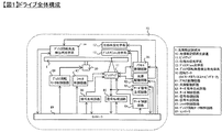
本発明の実施形態を添付図面にしたがって説明する。図1はホログラフィを利用してデジタル情報を記録及び/または再生する光情報記録媒体の記録再生装置の構成例を示すブロック図である。 Embodiments of the present invention will be described with reference to the accompanying drawings. FIG. 1 is a block diagram showing a configuration example of a recording / reproducing apparatus for an optical information recording medium that records and / or reproduces digital information using holography.
光情報記録再生装置10は、ピックアップ11、位相共役光学系12、ディスクCure光学系13、ディスク回転角度検出用光学系14、及び回転モータ50を備えており、光情報記録媒体1は回転モータ50によって回転可能な構成となっている。
The optical information recording / reproducing
ピックアップ11は、参照光と信号光を光情報記録媒体1に出射してホログラフィを利用してデジタル情報を光情報記録媒体に記録する役割を果たす。この際、記録する情報信号はコントローラ89によって信号生成回路86を介してピックアップ11内の空間光変調器に送り込まれ、信号光は空間光変調器によって変調される。
The pickup 11 plays a role of emitting reference light and signal light to the optical
光情報記録媒体1に記録した情報を再生する場合は、ピックアップ11から出射された参照光の位相共役光を位相共役光学系12にて生成する。ここで位相共役光とは、入力光と同一の波面を保ちながら逆方向に進む光波のことである。位相共役光によって再生される再生光をピックアップ11内の後述する光検出器によって検出し、信号処理回路85によって信号を再生する。
When reproducing the information recorded in the optical
光情報記録媒体1に照射する参照光と信号光の照射時間は、ピックアップ11内のシャッタの開閉時間をコントローラ89によってシャッタ制御回路87を介して制御することで調整できる。
The irradiation time of the reference light and the signal light applied to the optical
ディスクCure光学系13は、光情報記録媒体1のプリキュア及びポストキュアに用いる光ビームを生成する役割を果たす。プリキュアとは、光情報記録媒体1内の所望の位置に情報を記録する際、所望位置に参照光と信号光を照射する前に予め所定の光ビームを照射する前工程である。ポストキュアとは、光情報記録媒体1内の所望の位置に情報を記録した後、該所望の位置に追記不可能とするために所定の光ビームを照射する後工程である。
The disk cure optical system 13 serves to generate a light beam used for pre-cure and post-cure of the optical
ディスク回転角度検出用光学系14は、光情報記録媒体1の回転角度を検出するために用いられる。光情報記録媒体1を所定の回転角度に調整する場合は、ディスク回転角度検出用光学系14によって回転角度に応じた信号を検出し、検出された信号を用いてコントローラ89によってディスク回転モータ制御回路88を介して光情報記録媒体1の回転角度を制御する事が出来る。
The disk rotation angle detection
光源駆動回路82からは所定の光源駆動電流がピックアップ11、ディスクCure光学系13、ディスク回転角度検出用光学系14内の光源に供給され、各々の光源からは所定の光量で光ビームを発光することができる。
A predetermined light source driving current is supplied from the light
また、ピックアップ11、そして、ディスクCure光学系13は、光情報記録媒体1の半径方向に位置をスライドできる機構が設けられており、アクセス制御回路81を介して位置制御がおこなわれる。
Further, the pickup 11 and the disk cure optical system 13 are provided with a mechanism capable of sliding the position in the radial direction of the optical
ところで、ホログラフィの角度多重の原理を利用した記録技術は、参照光角度のずれに対する許容誤差が極めて小さくなる傾向がある。 By the way, the recording technique using the principle of angle multiplexing of holography tends to have a very small tolerance for the deviation of the reference beam angle.
従って、ピックアップ11内に、参照光角度のずれ量を検出する機構を設けて、サーボ信号生成回路83にてサーボ制御用の信号を生成し、サーボ制御回路84を介して該ずれ量を補正するためのサーボ機構を光情報記録再生装置10内に備えることが必要となる。
Therefore, a mechanism for detecting the deviation amount of the reference beam angle is provided in the pickup 11, a servo control signal is generated by the servo signal generation circuit 83, and the deviation amount is corrected via the servo control circuit 84. It is necessary to provide a servo mechanism for this purpose in the optical information recording / reproducing
また、ピックアップ11、ディスクCure光学系13、ディスク回転角度検出用光学系14は、いくつかの光学系構成または全ての光学系構成をひとつに纏めて簡素化しても構わない。
The pickup 11, the disk cure optical system 13, and the disk rotation angle detection
図2は、光情報記録再生装置10におけるピックアップ11の基本的な光学系構成の一例における記録原理を示したものである。光源201を出射した光ビームはコリメートレンズ202を透過し、シャッタ203に入射する。シャッタ203が開いている時は、光ビームはシャッタ203を通過した後、例えば2分の1波長板などで構成される光学素子204によってp偏光とs偏光の光量比が所望の比になるようになど偏光方向が制御された後、PBS(Polarization Beam Splitter)プリズム205に入射する。
FIG. 2 shows a recording principle in an example of a basic optical system configuration of the pickup 11 in the optical information recording / reproducing
PBSプリズム205を透過した光ビームは、信号光206として働き、ビームエキスパンダ208によって光ビーム径が拡大された後、位相マスク209、リレーレンズ210、PBSプリズム211を透過して空間光変調器212に入射する。
The light beam that has passed through the
空間光変調器212によって情報が付加された信号光は、PBSプリズム211を反射し、リレーレンズ213ならびに空間フィルタ214を伝播する。その後、信号光は対物レンズ215によって光情報記録媒体1に集光する。
The signal light to which information is added by the spatial
一方、PBSプリズム205を反射した光ビームは参照光207として働き、偏光方向変換素子216によって記録時または再生時に応じて所定の偏光方向に設定された後、ミラー217ならびにミラー218を経由してガルバノミラー219に入射する。ガルバノミラー219はアクチュエータ220によって角度を調整可能のため、レンズ221とレンズ222を通過した後に光情報記録媒体1に入射する参照光の入射角度を、所望の角度に設定することができる。なお、参照光の入射角度を設定するために、ガルバノミラーに代えて、参照光の波面を変換する素子を用いても構わない。
On the other hand, the light beam reflected by the
このように信号光と参照光とを光情報記録媒体1において、互いに重ね合うように入射させることで、光情報記録媒体内には干渉縞パターンが形成され、このパターンを光情報記録媒体に書き込むことで情報を記録する。また、ガルバノミラー219によって光情報記録媒体1に入射する参照光の入射角度を変化させることができるため、角度多重による記録が可能である。
In this way, by causing the signal light and the reference light to enter the optical
以降、同じ領域に参照光角度を変えて記録されたホログラムにおいて、1つ1つの参照光角度に対応したホログラムをページと呼び、同領域に角度多重されたページの集合をブックと呼ぶことにする。 Hereinafter, in holograms recorded in the same area with different reference beam angles, holograms corresponding to each reference beam angle are called pages, and a set of pages angle-multiplexed in the same area is called a book. .
図3は、光情報記録再生装置10におけるピックアップ11の基本的な光学系構成の一例における再生原理を示したものである。記録した情報を再生する場合は、前述したように参照光を光情報記録媒体1に入射し、光情報記録媒体1を透過した光ビームを、アクチュエータ223によって角度調整可能なガルバノミラー224にて反射させることで、その位相共役光を生成する。
FIG. 3 shows the principle of reproduction in an example of the basic optical system configuration of the pickup 11 in the optical information recording / reproducing
この位相共役光によって再生された信号光は、対物レンズ215、リレーレンズ213ならびに空間フィルタ214を伝播する。その後、信号光はPBSプリズム211を透過して光検出器225に入射し、記録した信号を再生することができる。
The signal light reproduced by the phase conjugate light propagates through the objective lens 215, the
図4は、光情報記録再生装置10における記録、再生の動作フローを示したものである。ここでは、特にホログラフィを利用した記録再生に関するフローを説明する。
FIG. 4 shows an operation flow of recording and reproduction in the optical information recording / reproducing
図4(a)は、光情報記録再生装置10に光情報記録媒体1を挿入した後、記録または再生の準備が完了するまでの動作フローを示し、図4(b)は準備完了状態から光情報記録媒体1に情報を記録するまでの動作フロー、図4(c)は準備完了状態から光情報記録媒体1に記録した情報を再生するまでの動作フローを示したものである。
FIG. 4A shows an operation flow from the insertion of the optical
図4(a)に示すように媒体を挿入すると(S401)、光情報記録再生装置10は、例えば挿入された媒体がホログラフィを利用してデジタル情報を記録または再生する媒体であるかどうかディスク判別を行う(S402)。
When the medium is inserted as shown in FIG. 4A (S401), the optical information recording / reproducing
ディスク判別の結果、ホログラフィを利用してデジタル情報を記録または再生する光情報記録媒体であると判断されると、光情報記録再生装置10は光情報記録媒体に設けられたコントロールデータを再生し(S403)、例えば光情報記録媒体に関する情報や、例えば記録や再生時における各種設定条件に関する情報を取得する。
As a result of disc discrimination, if it is determined that the optical information recording medium records or reproduces digital information using holography, the optical information recording / reproducing
コントロールデータを再生した後は、コントロールデータに応じた各種調整やピックアップ11に関わる学習処理(S404)を行い、光情報記録再生装置10は、記録または再生の準備が完了する(S405)。
After reproducing the control data, various adjustments according to the control data and learning processing (S404) relating to the pickup 11 are performed, and the optical information recording / reproducing
準備完了状態から情報を記録するまでの動作フローは図4(b)に示すように、まず記録するデータを受信して(S411)、該データに応じた情報をピックアップ11内の空間光変調器に送り込む。 As shown in FIG. 4B, the operation flow from the ready state to the recording of information is as follows. First, data to be recorded is received (S411), and information corresponding to the data is stored in the spatial light modulator in the pickup 11. To send.
その後、光情報記録媒体に高品質の情報を記録できるように、必要に応じて各種学習処理を事前に行い(S412)、シーク動作(S413)によりピックアップ11ならびにディスクCure光学系13の位置を光情報記録媒体の所定の位置に配置する。 Thereafter, various learning processes are performed in advance as necessary so that high-quality information can be recorded on the optical information recording medium (S412), and the positions of the pickup 11 and the disk Cure optical system 13 are optically determined by a seek operation (S413). It is arranged at a predetermined position on the information recording medium.
その後、ディスクCure光学系13から出射する光ビームを用いて所定の領域をプリキュアし(S414)、ピックアップ11から出射する参照光と信号光を用いてデータを記録する(S415)。 Thereafter, a predetermined area is pre-cured using the light beam emitted from the disk cure optical system 13 (S414), and data is recorded using the reference light and signal light emitted from the pickup 11 (S415).
データを記録した後は、必要に応じてデータをベリファイし(S416)、ディスクCure光学系13から出射する光ビームを用いてポストキュアを行う(S417)。 After the data is recorded, the data is verified as necessary (S416), and post-cure is performed using the light beam emitted from the disk Cure optical system 13 (S417).
準備完了状態から記録された情報を再生するまでの動作フローは図4(c)に示すように、光情報記録媒体から高品質の情報を再生できるように、必要に応じて各種学習処理を事前に行う(S421)。その後、シーク動作(S422)によりピックアップ11ならびに位相共役光学系12の位置を光情報記録媒体の所定の位置に配置する。
As shown in FIG. 4C, the operation flow from the ready state to the reproduction of the recorded information is performed in advance with various learning processes as necessary so that high-quality information can be reproduced from the optical information recording medium. (S421). Thereafter, the positions of the pickup 11 and the phase conjugate
その後、ピックアップ11から参照光を出射し、光情報記録媒体に記録された情報を再生する(S423)。本発明はこの情報を再生する際の信号品質を向上させるための手段として適用される。 Thereafter, reference light is emitted from the pickup 11 to reproduce the information recorded on the optical information recording medium (S423). The present invention is applied as means for improving the signal quality when reproducing this information.
本発明における実施例について以下で詳細に説明する。 Examples of the present invention will be described in detail below.
ページを分割し分割領域毎に適応等化を行う有効性について概説する。図5は同一ページ中の位置の違いによる再生品質の違いを模式的に表したものである。図5(a)上図に図示されているような白色のON画素の周囲を黒色のOFF画素が囲んでいる場合、記録時の空間光変調器では図5(a)下図に表されるようにON画素と隣接OFF画素は2値で表される。しかし、前記信号をホログラムとして光情報記録媒体に記録し再生信号を見た場合、図5(b)上図に示されるようにON画素から隣接する画素へ信号が漏れ込み符号間干渉が生じる。これは、特開2004−272268号公報(特許文献1)に記載されるビームウエストを絞り込む開口(空間フィルタ)が高周波成分を除去するためであり、開口のサイズを小さくすればする程、符号間干渉は大きくなる。 The effectiveness of dividing a page and performing adaptive equalization for each divided area will be outlined. FIG. 5 schematically shows a difference in reproduction quality due to a difference in position on the same page. When a black OFF pixel surrounds a white ON pixel as shown in the upper diagram of FIG. 5A, the spatial light modulator at the time of recording is represented by the lower diagram of FIG. In addition, ON pixels and adjacent OFF pixels are represented by binary values. However, when the signal is recorded as a hologram on an optical information recording medium and the reproduced signal is viewed, the signal leaks from the ON pixel to the adjacent pixel as shown in the upper diagram of FIG. This is because the aperture (spatial filter) for narrowing the beam waist described in Japanese Patent Application Laid-Open No. 2004-272268 (Patent Document 1) removes high-frequency components. Interference increases.
前記符号間干渉はレンズの収差やレーザの波長ずれ、ディスクチルト等の複合的な外乱によりページ中の位置で干渉の様子が変化する場合がある。例えば、あるホログラムからの再生ページを図5(c)で図示されるように5つの領域に分けてON画素からの隣接OFF画素への漏れ込みの違いを観察すると、図5(b)下図のようにページ中の位置により干渉の様子が異なる場合がある。このような同一ページ中での符号間干渉の違いには、従来から提案されている1ページに対して1つのフィルタ係数を求めるページ適応型の適応等化では十分に対応することが難しく、ページをある大きさの領域に分割させ領域毎に適応等化を行う本発明が有効である。 The intersymbol interference may change at a position in the page due to a complex disturbance such as lens aberration, laser wavelength shift, and disc tilt. For example, when a reproduction page from a certain hologram is divided into five regions as shown in FIG. 5C and the difference in leakage from the ON pixel to the adjacent OFF pixel is observed, the lower diagram of FIG. Thus, the state of interference may differ depending on the position in the page. Such a difference in intersymbol interference in the same page cannot be sufficiently dealt with by page-adaptive adaptive equalization in which one filter coefficient is obtained for one page, which has been conventionally proposed. It is effective to apply the present invention to divide the image into areas of a certain size and perform adaptive equalization for each area.
図6は2次元画素に対するFIRフィルタ処理の一例を示したものである。例えば図6(a)に示すように3×3のフィルタ領域で中心の注目画素の輝度値をフィルタ処理する場合を考える。フィルタ処理としては、図6(b)で表されるように注目画素及び隣接画素1〜8の各々の輝度値に対してフィルタ係数を乗算回路301〜309を用いて乗算し、これらの値の全てを加算回路310を用いて加算することによりフィルタ後の値を算出する。当然、3×3のフィルタ領域を仮定した場合フィルタ係数の値は9つ必要となる。なお、本発明は3×3のフィルタ領域に限定されるものではなく、任意の大きさのフィルタ領域を使用して構わない。
FIG. 6 shows an example of FIR filter processing for a two-dimensional pixel. For example, as shown in FIG. 6A, consider a case where the luminance value of the pixel of interest at the center is filtered in a 3 × 3 filter region. As the filter processing, as shown in FIG. 6B, the luminance values of the target pixel and the
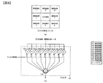
図7は第1の実施例におけるページを分割する方法の一例を示したものである。例えば、図7(a)に示されるような再生ページが得られた場合、太枠で示されるようにある大きさの複数の領域群に再生ページを分割する。その後、領域毎に線形最小平均自乗誤差法LMMSE(Linear Minimun Mean Squared Error)等の適応アルゴリズムを用いてフィルタ係数を算出し、領域毎に等化処理する。等化する際、各領域のエッジ部でも効率的な等化性能を実現するため数画素分余分にフィルタ処理し、該当部分のみを等化後の領域として抜き出しても構わない。なお、本例では16分割した場合を図示しているが、本発明は16分割に限定されるものではない。また、分割領域の大きさも各領域で同一の大きさを図示しているが、領域毎に大きさを変更しても構わない。 FIG. 7 shows an example of a method for dividing a page in the first embodiment. For example, when a reproduction page as shown in FIG. 7A is obtained, the reproduction page is divided into a plurality of area groups having a certain size as indicated by a thick frame. Thereafter, a filter coefficient is calculated for each region by using an adaptive algorithm such as a linear minimum mean square error method LMMSE (Linear Minimum Mean Squared Error), and equalization processing is performed for each region. When performing equalization, in order to achieve efficient equalization performance even at the edge portion of each region, it is possible to perform extra filtering for several pixels and extract only the relevant portion as the region after equalization. In this example, the case of 16 divisions is illustrated, but the present invention is not limited to 16 divisions. In addition, the size of the divided area is the same in each area, but the size may be changed for each area.
LMMSEアルゴリズムについて説明する。LMMSEは非特許文献Japanese Journal of Applied Physics Vol.45、No.2B、2006、PP.1079−1083に記載されるように等化後の信号と理想信号との自乗誤差の平均値が最小となる場合のフィルタ係数を算出するアルゴリズムであり、算出式は式(1)で表される。 The LMMSE algorithm will be described. LMMSE is a non-patent document, Japan Journal of Applied Physics Vol. 45, no. 2B, 2006, PP. As described in 1079-1083, this is an algorithm for calculating a filter coefficient when the average value of the square error between the equalized signal and the ideal signal is minimum, and the calculation formula is expressed by Formula (1). .
w=RdiRii −1 ・・・式(1)
ここで、wはLMMSEにより求められるフィルタ係数、Rdiは入力画素と理想画素の相互相関、Riiは入力画素の自己相関である。なお、適応アルゴリズムとしてLMMSE以外のアルゴリズムを使用しても構わない。
w = R di R ii -1 Formula (1)
Here, w is a filter coefficient obtained by LMMSE, R di is a cross-correlation between an input pixel and an ideal pixel, and R ii is an auto-correlation of the input pixel. An algorithm other than LMMSE may be used as the adaptive algorithm.
ページを複数の領域群に分割し分割領域毎に適応等化を行う動作の一例を図8に示す。まずステップ301により光情報記録媒体から再生されたページをある大きさの複数の領域群に分割する。その後、ステップ302により分割領域毎にLMMSE等の適応アルゴリズムを用いてフィルタ係数を算出する。ステップ303において、ステップ302で求めた各領域のフィルタ係数群を用いて分割領域毎に等化処理を行う。ステップ304において、分割領域群を分割前のページと同じ状態に戻るように、分割前の位置に再配置させ結合することでページデータ化する。ステップ306において最終ページかどうかの判断を行い、最終ページの場合は処理を終了し、最終ページで無い場合には、ステップ305により次ページに移り、ステップ301からの動作を実行する。なお、図8では分割領域毎のフィルタ係数群を全て求めた後にフィルタ処理を行う例を示したが、各分割領域でフィルタ係数を求めた後に続けてフィルタ処理を行う動作を全分割領域で行っても構わない。
An example of an operation for dividing a page into a plurality of region groups and performing adaptive equalization for each divided region is shown in FIG. First, in
続いて第1の実施例の装置構成を図9に示す。ピックアップ11で検出されたページデータはページ位置合わせ回路351により位置ずれ等の調整が行われる。ずれ量の算出はページ中に埋め込まれた既知パターンを元に行われ、水平方向及び垂直方向の位置ずれ、回転ずれ、倍率ずれを算出し、これらの情報を元に検出画像の位置合わせを回路351により行う。その後、オーバーサンプリング解除回路352によりページ中の1画素が記録時の空間光変調器212におけるONあるいはOFFのいずれかの信号と1対1に対応するように調整される。これは、ページの位置ずれがある場合にも十分な再生性能を確保するため光検出器225の解像度は一般的に空間光変調器212の解像度よりも高くなっているためである。その後、ページ分割回路353によりある大きさの複数の領域群にページを分割し、フィルタ係数演算回路356により領域毎にフィルタ係数を求める。なお、フィルタ係数演算回路では理想信号が必要となるため、ページ分割回路353の出力は同時に等化回路354に渡され等化処理しその後2値化回路355により2値化され理想信号としてフィルタ係数演算回路に渡される。なお、2値化回路355は閾値によりON、OFFの判断を行っても良いし、ビタビ復号を利用しても良いし,SUM−PRODUCT復号等の誤り訂正符号の軟判定復号技術により2値化しても構わない。また、本実施例をPartial Response Maximum Likelihood(PRML)のPR等化器として用いる場合には、2値化回路355の後に所望のPR特性となるように畳み込みを行うフィルタを配置しても構わない。可変FIRフィルタ357ではフィルタ係数演算回路356で算出した係数群を用いて分割領域毎にフィルタ処理を施す。その後、ページ結合回路359により分割領域群を元のページの状態に戻るように結合させ、2値化回路358によりON、OFFの2値化を行いコントローラ89に情報を渡す。なお、本実施例ではフィルタ係数演算回路での理想信号として2値化回路355を用いたが、ページ中に埋め込まれた前期既知パターンを用いてフィルタ係数群を演算しても構わない。また、2値化回路358においても2値化回路355と同様に閾値によりON、OFFの判断を行っても良いし、ビタビ復号を利用しても良いし,SUM−PRODUCT復号等の誤り訂正符号の軟判定復号技術により2値化しても構わない。
Next, FIG. 9 shows the apparatus configuration of the first embodiment. The page data detected by the pickup 11 is adjusted by a
本実施例により、ページ中の位置の違いによる再生品質及び符号間干渉の違いに対応した等化が可能であり、ページ全体としての再生品質を向上させることができる。また、分割された領域毎の適応等化を並列処理化することにより信号再生の高速化が可能である。なお,本実施例では角度多重方式のホログラム記録技術ムログラフィいいCTに基づく説明を記述したが,本発明は角度多重方式に限定されるものでは無く,シフト多重方式等の他のホログラフム記録技術や,ホログラム以外の光情報記録媒体における信号処理に利用しても構わない。 According to the present embodiment, equalization corresponding to the difference in reproduction quality and intersymbol interference due to the difference in position in the page is possible, and the reproduction quality of the entire page can be improved. In addition, it is possible to speed up signal reproduction by performing parallel processing of adaptive equalization for each divided area. In the present embodiment, the description based on CT which is a good holographic recording technology for angle multiplexing method is described, but the present invention is not limited to the angle multiplexing method, and other holographic recording technology such as shift multiplexing method, You may utilize for the signal processing in optical information recording media other than a hologram.
以降の説明において,実施例1と共通する部分は説明を省略する。図10は第2の実施例におけるページを分割する方法の一例を示したものである。まず、実施例1と同様にページをある大きさの複数の領域群に分割する。その後、信号品質が近い領域は図10(a)に示すように結合することで領域を拡大する。この場合の信号品質としては、例えば以下の式(2)あるいは式(3)で表されるSNRや輝度平均が考えられる。 In the following description, description of parts common to the first embodiment will be omitted. FIG. 10 shows an example of a method for dividing a page in the second embodiment. First, as in the first embodiment, the page is divided into a plurality of area groups having a certain size. Thereafter, the areas having close signal quality are combined as shown in FIG. As signal quality in this case, for example, SNR and luminance average represented by the following formula (2) or formula (3) are conceivable.
SNR=(μON+μOFF)/(σON+σOFF)・・・(2)
SNR=(μON+μOFF)/(σON 2+σOFF 2)0.5・・・(3)
ここで、μON及びμOFFはそれぞれON画素及びOFF画素の平均輝度を、σON及びσOFFはそれぞれON画素及びOFF画素の標準偏差を表す。本実施例では、信号品質が似ていれば隣接していない領域同士でも結合する場合がある。そのため領域の接合部の影響により誤差量が増加する可能性があるが、接合部の拡大領域中に占める割合は少ないため、誤差量の自乗平均を最小にするLMMSEアルゴリズムの特性からあまり問題とはならない。またページ中での位置情報を基にして、対称性のある領域は纏めるなどの方法や、図10(b)のように単純に位置が近い領域を纏めるといった方法が考えられる。
SNR = (μ ON + μ OFF ) / (σ ON + σ OFF ) (2)
SNR = (μ ON + μ OFF ) / (σ ON 2 + σ OFF 2 ) 0.5 (3)
Here, μ ON and μ OFF represent the average luminance of the ON pixel and the OFF pixel, respectively, and σ ON and σ OFF represent the standard deviation of the ON pixel and the OFF pixel, respectively. In this embodiment, if the signal quality is similar, even regions that are not adjacent may be combined. Therefore, there is a possibility that the amount of error increases due to the influence of the joint portion of the region, but since the ratio of the joint portion in the enlarged region is small, the problem is not so much due to the characteristics of the LMMSE algorithm that minimizes the mean square of the error amount. Don't be. Further, based on position information in the page, a method of collecting symmetric regions, or a method of simply collecting regions close to each other as shown in FIG.
図11は本実施例における動作の流れの一例を表している。ステップ401においてページをある大きさの複数の領域群に分割させる。その後、ステップ402において前述したようにSNRや輝度平均等の情報を基に再生品質が近いと考えられる領域群を結合することで領域を拡大させる。ステップ403において、分割領域毎にLMMSEなどのアルゴリズムを用いてフィルタ係数群を算出し、ステップ404において、分割領域毎にFIRフィルタ処理を行う。ステップ405においてステップ402で結合した領域を再度分割させ、ステップ406において、分割領域群を分割前のページと同じ状態に戻るように、分割前の位置に再配置させ結合することでページデータ化する。ステップ407において最終ページかどうかの判断を行い、最終ページの場合は処理を終了し、最終ページで無い場合には、ステップ408により次ページに移り、ステップ401からの動作を実行する。
FIG. 11 shows an example of the operation flow in this embodiment. In
図12は第2の実施例の装置構成の一例を示している。なお実施例1と共通の部分については説明を省略する。本実施例では、ページ分割回路353でページを複数領域群に分割した後に、ページ結合回路360により信号品質の近い領域を結合させる。その後、実施例1と同様の装置構成を経て、可変FIRフィルタ357の後にページ分割回路361を配置することにより、ページ結合回路360で結合する前の領域群の状態に戻し、ページ結合回路359により元のページ状態に戻るように結合させる。なお、ページ中の位置情報が近いものを纏めるという処理をした場合等で、ページ分割回路361が無くてもページ結合回路359によりページ化が可能な場合は、ページ分割回路361は省略することができる。なお、実施例1と同様にPartial Response Maximum Likelihood(PRML)のPR等化器として用いる場合には、2値化回路355の後に所望のPR特性となるように畳み込みを行うフィルタを配置しても構わない。
FIG. 12 shows an example of the apparatus configuration of the second embodiment. Note that description of portions common to the first embodiment is omitted. In the present embodiment, after the page is divided into a plurality of area groups by the
本実施例では実施例1で記述したメリットに加えて、信号品質が近い領域を纏めることにより1つのフィルタ係数を求める際のサンプル数が増加するため精度が良い係数を算出することが可能となる。また、フィルタ係数群の数を減少させることができるため纏め方によっては実施例1に比べて回路規模を低減することが可能である。 In the present embodiment, in addition to the advantages described in the first embodiment, the number of samples for obtaining one filter coefficient increases by collecting regions having close signal qualities, so that a highly accurate coefficient can be calculated. . In addition, since the number of filter coefficient groups can be reduced, the circuit scale can be reduced as compared with the first embodiment depending on how to group them.
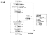
図13は分割領域毎に適応等化する方法の第3の実施例の動作の流れの一例を示したものである。本実施例では、ページ全体から1つのフィルタ係数を算出した後、分割領域毎の係数となるように前記フィルタ係数を修正し分割領域毎に等化する。まずステップ501によりページ全体からLMMSE等の適応アルゴリズムを用いて1つのフィルタ係数を算出する。その後、ステップ502によりページをある大きさの複数の領域群に分割する。ステップ503において分割領域内の既知パターンに移る。本既知パターンは実施例1で記述したずれ量算出用の既知パターンを用いても良いし、フィルタ係数を求めるための既知パターンとして新規にページに埋め込んだものを使用しても構わない。ステップ504において前記ステップ501で算出したフィルタ係数を初期値として各分割領域の符号間干渉を効果的に除去できるフィルタ係数群となるようにLMSアルゴリズム等を用いて修正する。ステップ505において分割領域毎にFIRフィルタ処理し、ステップ506において最後の分割領域かどうかの判断を行う。最後の分割領域ではない場合は、ステップ507において次の分割領域に移り、ステップ503からの処理に戻る。最後の分割領域の場合はステップ508において、分割領域群を分割前のページと同じ状態に戻るように、分割前の位置に再配置させ結合することでページデータ化する。ステップ509において最終ページかどうかの判断を行い、最終ページの場合は処理を終了し、最終ページで無い場合には、ステップ510により次ページに移り、ステップ501からの動作を実行する。
FIG. 13 shows an example of the operation flow of the third embodiment of the method for adaptive equalization for each divided region. In this embodiment, after calculating one filter coefficient from the entire page, the filter coefficient is corrected so as to be a coefficient for each divided region, and equalized for each divided region. First, in step 501, one filter coefficient is calculated from the entire page using an adaptive algorithm such as LMMSE. Thereafter, in
図14はLMSアルゴリズムによりフィルタ係数を更新する順序の例を示している。例えば、(a)のように既知部内を上下に順番に読んで行き係数を更新しても構わないし、(b)のように左右に順番に読んで行き係数を更新しても構わない、また(c)のように外周部から中心あるいはその逆に中心部から外周部に読んで行き係数を更新しても構わない。LMSでは以下の式(4)によりフィルタ係数を更新する。
w(n+1)=w(n)+μe(n)i(n)・・・(4)
FIG. 14 shows an example of the order of updating the filter coefficients by the LMS algorithm. For example, as shown in (a), the inside of the known part may be read up and down in order, and the going coefficient may be updated, or as shown in (b), the going coefficient may be read up and down in order, and the going coefficient may be updated. As shown in (c), the going coefficient may be updated by reading from the center to the center or vice versa. In LMS, the filter coefficient is updated by the following equation (4).
w (n + 1) = w (n) + μe (n) i (n) (4)
ここで、w(n+1)は(n+1)番目のフィルタ係数、w(n)はn番目のフィルタ係数、μはステップサイズパラメータ、e(n)はn番目のフィルタ係数を用いて等化した際の理想値との誤差、i(n)はn番目のフィルタ回路への入力を示している。 Here, w (n + 1) is the (n + 1) th filter coefficient, w (n) is the nth filter coefficient, μ is the step size parameter, and e (n) is equalized using the nth filter coefficient. I (n) indicates an input to the nth filter circuit.
図15は、第3の実施例の装置構成の一例を示している。なお実施例1と共通の部分については説明を省略する。オーバーサンプリング解除回路352の後にフィルタ係数演算回路356を配置させることによりページ全体からフィルタ係数を算出する。このときのフィルタ係数演算回路356は理想信号が必要なため等化回路354で等化処理し2値化回路355で2値化することで理想信号とする。オーバーサンプリング解除回路352からの信号はページ分割回路353によりある大きさの領域群に分割される。その後画像抽出回路364により各領域中の既知部を抽出し、本既知部を可変FIRフィルタ357でフィルタ処理する。なお、フィルタ係数の初期値としてはフィルタ係数演算回路356の出力を用いる。誤差算出回路365ではコントローラ89から受け取った既知部の実際の値と可変FIRフィルタの出力を比較し誤差量を算出する。その後、前述したLMSアルゴリズムを用いてフィルタ係数演算回路366を用いてフィルタ係数を更新する。本処理を既知部の全ての画素で行いフィルタ係数を逐次領域毎の係数となるように更新させる。全ての分割領域で同様の処理を行い分割領域毎のフィルタ係数群を算出する。前記領域毎のフィルタ係数群を用いて可変FIRフィルタ367によりページ分割回路353により複数領域に分割されたページを領域毎にフィルタ処理し、ページ結合器359により元のページ状態になるように結合させる。最後に2値化回路358により2値化処理しコントローラ89に渡す。なお、実施例1と同様にPartial Response Maximum Likelihood(PRML)のPR等化器として用いる場合には、2値化回路355の後及びコントローラ89と誤差算出回路365の間に所望のPR特性となるように畳み込みを行うフィルタを配置しても構わない。また、LMSでフィルタ係数を更新する際の初期値は前述したようにページ全体から算出したフィルタ係数を使用しても構わないし、特性の似ていると考えられる分割領域でLMSにより更新したフィルタ係数を初期値としても構わない。
FIG. 15 shows an example of the apparatus configuration of the third embodiment. Note that description of portions common to the first embodiment is omitted. By disposing a filter
本実施例では実施例1で記述したメリットに加えて、既知部を用いてフィルタ係数群を算出するため、適応アルゴリズムにおいて理想信号としてのエラーの混在は皆無であり精度の良いフィルタ係数群を算出できる可能性がある。 In this embodiment, in addition to the merits described in the first embodiment, the filter coefficient group is calculated using the known portion. Therefore, there is no mixed error as an ideal signal in the adaptive algorithm, and a high-precision filter coefficient group is calculated. There is a possibility.
図16は分割領域毎に適応等化する方法の第4の実施例を模式的に表したものである。本実施例では、フィルタ係数算出用の既知ページをブック中の最初及び、データページの間に定期的に挟みこみ、実施例1から3に記述したいずれかの方法を用いて本既知ページから分割領域毎のフィルタ係数群を算出する。なお、データページでの等化処理としては前記既知ページで求めたフィルタ係数群をそのまま使用し、分割領域毎にフィルタ処理する。なお、図16では1ブック中に2つの既知ページを挟む例を示したが、既知ページを挟む頻度は任意であり、本図の方法に限定されるものではない。 FIG. 16 schematically shows a fourth embodiment of a method for adaptive equalization for each divided region. In this embodiment, a known page for calculating the filter coefficient is periodically sandwiched between the first page and the data page in the book, and divided from the known page using any of the methods described in the first to third embodiments. A filter coefficient group for each region is calculated. As the equalization process on the data page, the filter coefficient group obtained on the known page is used as it is, and the filter process is performed for each divided region. Although FIG. 16 shows an example in which two known pages are sandwiched in one book, the frequency of sandwiching the known pages is arbitrary and is not limited to the method shown in FIG.
図17は、第4の実施例の動作の流れの一例を示したものである。まず、ステップ601においてページをある大きさの複数の領域群に分割する。ステップ602において既知ページかの判断を行い、既知ページの場合はステップ607により分割領域毎にフィルタ係数を算出しステップ608により次ページへ移り、ステップ601に戻る。なお、既知ページかどうかの判断では、ページ番号から判断しても構わないし、あらかじめページ中に既知ページであること示す情報を埋め込んでおき判断しても構わない。ステップ602において既知ページでなかった場合は、ステップ603及びステップ604において既知ページで求めたフィルタ係数群を用いて分割領域毎にフィルタ処理する。ステップ605において、分割領域群を分割前のページと同じ状態に戻るように、分割前の位置に再配置させ結合することでページデータ化する。ステップ606において最終ページかどうかの判断を行い、最終ページの場合は処理を終了し、最終ページで無い場合には、ステップ609により次ページに移り、ステップ601からの動作を実行する。
FIG. 17 shows an example of the operation flow of the fourth embodiment. First, in step 601, a page is divided into a plurality of area groups having a certain size. In step 602, it is determined whether the page is a known page. If the page is a known page, a filter coefficient is calculated for each divided region in
図18は第4の実施例の装置構成の一例を示している。なお実施例1と共通の部分については説明を省略する。オーバーサンプリング解除装置352の後に既知ページ判断回路368により既知ページかどうかの判断を行う。その後、ページ分割回路353によりある大きさの領域群にページを分割する。処理しているページが既知ページの場合は、フィルタ係数演算回路356により分割領域毎のフィルタ係数群を算出する。なお、ここでの理想信号はコントローラ89から得られる。処理しているページが既知ページではない場合には可変FIRフィルタ357により既知ページを用いてフィルタ係数演算回路356から算出したフィルタ係数群を用いてフィルタ処理する。その後、ページ結合回路359により元のページ状態に戻るように分割領域群を結合させ、2値化回路358により2値化しコントローラ89に渡す。
FIG. 18 shows an example of the apparatus configuration of the fourth embodiment. Note that description of portions common to the first embodiment is omitted. After the oversampling release device 352, the known page determination circuit 368 determines whether the page is a known page. Thereafter, the page is divided into a region group of a certain size by the
本実施例では実施例1で記述したメリットに加えて、実施例3と同様に既知部を用いてフィルタ係数群を算出することに加え、既知部がページ全体とサンプル数が非常に多いため実施例3よりも精度の良いフィルタ係数群を算出できる可能性がある。また、全ページで適応アルゴリズムを実行するのではなく既知ページのみで実行するため、他の実施例に比べて再生速度を高速化することが可能となる。 In the present embodiment, in addition to the merit described in the first embodiment, in addition to calculating the filter coefficient group using the known portion as in the third embodiment, the known portion is implemented because the entire page and the number of samples are very large. There is a possibility that a filter coefficient group with higher accuracy than in Example 3 can be calculated. In addition, since the adaptive algorithm is not executed on all pages but only on known pages, the reproduction speed can be increased as compared with other embodiments.
1・・・光情報記録媒体、10・・・光情報記録再生装置、11・・・ピックアップ、
12・・・位相共役光学系、13・・・ディスクCure光学系、
14・・・ディスク回転角度検出用光学系、50・・・回転モータ、
81・・・アクセス制御回路、82・・・光源駆動回路、83・・・サーボ信号生成回路、
84・・・サーボ制御回路、85・・・信号処理回路、86・・・信号生成回路、
87・・・シャッタ制御回路、88・・・ディスク回転モータ制御回路、
89・・・コントローラ、
201・・・光源、202・・・コリメートレンズ、203・・・シャッタ、
204・・・1/2波長板、205・・・偏光ビームスプリッタ、
206・・・信号光、207・・・参照光、
208・・・ビームエキスパンダ、209・・フェーズ(位相)マスク、
210・・・リレーレンズ、211・・・偏光ビームスプリッタ、
212・・・空間光変調器、213・・・リレーレンズ、214・・・空間フィルタ、
215・・・対物レンズ、216・・・偏光方向変換素子、217・・・ミラー、
218・・・ミラー、219・・・ミラー、220・・・アクチュエータ、
221・・・レンズ、222・・・レンズ、223・・・アクチュエータ、
224・・・ミラー、225・・・光検出器、
351・・・ページ位置合わせ回路、352・・・オーバーサンプリング解除回路、
353・・・ページ分割回路、354・・・等化回路、355・・・2値化回路、
356・・・フィルタ係数演算回路、357・・・可変FIRフィルタ、
358・・・2値化回路、
359・・・ページ結合回路、360・・・ページ結合回路、
361・・・ページ分割回路、364・・・画像抽出回路、365・・・誤差算出回路、
366・・・フィルタ係数演算回路、367・・・可変FIRフィルタ、
368・・・既知ページ判断回路
DESCRIPTION OF
12 ... Phase conjugate optical system, 13 ... Disc Cure optical system,
14 ... Optical system for detecting the disk rotation angle, 50 ... Rotation motor,
81 ... Access control circuit, 82 ... Light source driving circuit, 83 ... Servo signal generation circuit,
84 ... Servo control circuit, 85 ... Signal processing circuit, 86 ... Signal generation circuit,
87 ... Shutter control circuit, 88 ... Disc rotation motor control circuit,
89 ... Controller,
201 ... light source, 202 ... collimating lens, 203 ... shutter,
204 ... 1/2 wavelength plate, 205 ... polarizing beam splitter,
206: Signal light, 207: Reference light,
208... Beam expander, 209 .. Phase mask,
210 ... relay lens, 211 ... polarizing beam splitter,
212 ... Spatial light modulator, 213 ... Relay lens, 214 ... Spatial filter,
215 ... Objective lens, 216 ... Polarization direction conversion element, 217 ... Mirror,
218 ... mirror, 219 ... mirror, 220 ... actuator,
221 ... lens, 222 ... lens, 223 ... actuator,
224 ... mirror, 225 ... photodetector,
351: Page alignment circuit, 352 ... Oversampling cancel circuit,
353 ... Page division circuit, 354 ... Equalization circuit, 355 ... Binarization circuit,
356: Filter coefficient arithmetic circuit, 357: Variable FIR filter,
358... Binarization circuit,
359 ... Page combining circuit, 360 ... Page combining circuit,
361 ... Page division circuit, 364 ... Image extraction circuit, 365 ... Error calculation circuit,
366... Filter coefficient arithmetic circuit, 367... Variable FIR filter,
368 ... Known page determination circuit
Claims (12)
光情報記録媒体から2次元信号を再生するピックアップと、
前記ピックアップから再生された2次元信号を少なくとも2つ以上の2次元信号群に分割する分割手段と、
前記分割手段で分割された分割2次元信号群毎に対応する等化後の分割2次元信号群の信号と該分割2次元信号群毎に対応する目標信号との誤差量が小さくなるように、分割2次元信号群毎にフィルタ係数を算出し、該算出されたフィルタ係数を用いて分割2次元信号群毎に等化する適応等化回路と、
前記適応等化回路から出力される分割2次元信号群を結合する結合手段と、
前記結合手段から出力される2次元信号を2値化する2値化回路と、
を具備する光情報再生装置。 An optical information reproducing device for reproducing information using holography,
A pickup for reproducing a two-dimensional signal from an optical information recording medium;
Dividing means for dividing the two-dimensional signal reproduced from the pickup into at least two two-dimensional signal groups;
The error amount between the signal of the divided two-dimensional signal group after equalization corresponding to each divided two-dimensional signal group divided by the dividing unit and the target signal corresponding to each divided two-dimensional signal group is reduced. An adaptive equalization circuit that calculates a filter coefficient for each divided two-dimensional signal group, and equalizes each divided two-dimensional signal group using the calculated filter coefficient;
Coupling means for coupling the divided two-dimensional signal group output from the adaptive equalization circuit;
A binarization circuit for binarizing the two-dimensional signal output from the combining unit;
An optical information reproducing apparatus comprising:
再生された2次元信号を所定の大きさの2次元信号群に分割する分割回路で構成されることを特徴とする請求項1に記載の光情報再生装置。 The dividing means includes
2. The optical information reproducing apparatus according to claim 1, comprising a dividing circuit that divides the reproduced two-dimensional signal into a two-dimensional signal group having a predetermined size.
前記第1の結合手段で結合された前記第2の2次元信号群を再度分割する第2の分割手段と、
前記第2の分割手段で分割された2次元信号群を結合する第2の結合手段と、
を具備し、
前記適応等化回路は、前記第1の結合手段から出力される前記第2の分割2次元信号群毎にフィルタ係数を算出し、該算出されたフィルタ係数を用いて前記第2の分割2次元信号群毎に等化することを特徴とする請求項1に記載の光情報再生装置。 Based the divided split two-dimensional signal group in said dividing means to a predetermined information, a first coupling means for coupling to a larger second divided 2-dimensional signal group from the divided two-dimensional signal group,
Second dividing means for dividing again the second two-dimensional signal group combined by the first combining means;
Second combining means for combining the two-dimensional signal group divided by the second dividing means;
Equipped with,
The adaptive equalization circuit calculates a filter coefficient for each second divided two-dimensional signal group output from the first combining unit, and uses the calculated filter coefficient to calculate the second divided two-dimensional signal. The optical information reproducing apparatus according to claim 1 , wherein equalization is performed for each signal group .
光情報記録媒体から2次元信号を再生するピックアップと、
前記ピックアップから再生された2次元信号を所定の目標特性に等化するためのフィルタ係数を求めるための第1の係数演算回路と、
再生された2次元信号を2次元信号群に分割する分割回路と、
以前に求めたフィルタ係数を初期値として前記分割回路で分割された分割2次元信号群毎に対応する等化後の分割2次元信号群の信号と該分割2次元信号群毎に対応する目標信号との誤差量が小さくなるように、分割2次元信号群毎のフィルタ係数を求めるための第2の係数演算回路と、
前記第2の係数演算回路から出力される係数を用いて前記2次元信号群を等化するフィルタと、
前記フィルタから出力される2次元信号群を前記分割回路で分割される以前の2次元信号の状態に結合する結合回路と、
前記結合回路から出力される2次元信号を2値化する2値化回路と、
を具備する光情報再生装置。 An optical information reproducing device for reproducing information using holography,
A pickup for reproducing a two-dimensional signal from an optical information recording medium;
A first coefficient calculation circuit for obtaining a filter coefficient for equalizing the two-dimensional signal reproduced from the pickup to a predetermined target characteristic;
A dividing circuit for dividing the reproduced two-dimensional signal into a two-dimensional signal group;
The signal of the divided two-dimensional signal group after equalization corresponding to each divided two-dimensional signal group divided by the dividing circuit using the previously obtained filter coefficient as an initial value and the target signal corresponding to each divided two-dimensional signal group A second coefficient arithmetic circuit for obtaining a filter coefficient for each divided two-dimensional signal group,
A filter for equalizing the two-dimensional signal group using a coefficient output from the second coefficient arithmetic circuit;
A coupling circuit that couples the two-dimensional signal group output from the filter to the state of the two-dimensional signal before being divided by the dividing circuit;
A binarization circuit that binarizes the two-dimensional signal output from the coupling circuit ;
An optical information reproducing apparatus comprising:
光情報記録媒体から2次元情報を再生するピックアップと、
再生された既知の2次元信号及びユーザーデータを含む2次元信号を2次元信号群に分割する分割回路と、
前記既知の2次元信号を分割した分割2次元信号群毎に対応する等化後の分割2次元信号群の信号と該分割2次元信号群毎に対応する目標信号との誤差量が小さくなるように、分割2次元信号群毎にフィルタ係数を求めるための係数演算回路と、
前記係数演算回路から出力される係数を用いて前記ユーザーデータを含む分割2次元信号群毎に等化するフィルタと、
前記フィルタから出力される2次元信号群を前記分割回路で分割される以前の2次元信号の状態に結合する結合回路と、
前記結合回路から出力される2次元信号を2値化する2値化回路と
を具備する光情報再生装置。 An optical information reproducing device for reproducing information using holography,
A pickup for reproducing two-dimensional information from an optical information recording medium;
A dividing circuit for dividing a reproduced two-dimensional signal including a known two-dimensional signal and user data into a two-dimensional signal group;
An error amount between the equalized divided two-dimensional signal group signal corresponding to each divided two-dimensional signal group obtained by dividing the known two-dimensional signal and the target signal corresponding to each divided two-dimensional signal group is reduced. A coefficient calculation circuit for obtaining a filter coefficient for each divided two-dimensional signal group;
A filter that equalizes each divided two-dimensional signal group including the user data using a coefficient output from the coefficient arithmetic circuit ;
A coupling circuit that couples the two-dimensional signal group output from the filter to the state of the two-dimensional signal before being divided by the dividing circuit;
An optical information reproducing apparatus comprising: a binarization circuit that binarizes a two-dimensional signal output from the coupling circuit.
光情報記録媒体から2次元信号を再生する工程と、
再生された2次元信号を分割2次元信号群に分割する分割工程と、
前記分割工程で得られる分割2次元信号群に対応する等化後の分割2次元信号群の信号と該分割2次元信号群毎に対応する目標信号との誤差量が小さくなるように、分割2次元信号群毎にフィルタ係数を算出し、該算出されたフィルタ係数を用いて分割2次元信号群毎に等化する適応等化工程と、
前記適応等化工程で得られる分割2次元信号群を結合する結合工程と、
前記結合工程で得られる2次元信号を2値化する2値化工程と、
を含むことを特徴とする光情報再生方法。 An optical information reproduction method for reproducing information using holography,
Reproducing a two-dimensional signal from an optical information recording medium;
A dividing step of dividing the reproduced two-dimensional signal into divided two-dimensional signal groups;
Division 2 so that the error amount between the signal of the divided two-dimensional signal group after equalization corresponding to the divided two-dimensional signal group obtained in the division step and the target signal corresponding to each divided two-dimensional signal group is small. An adaptive equalization step of calculating a filter coefficient for each dimension signal group and equalizing for each divided two-dimensional signal group using the calculated filter coefficient;
A combining step of combining the divided two-dimensional signal groups obtained in the adaptive equalization step;
A binarization step for binarizing the two-dimensional signal obtained in the combining step;
An optical information reproducing method comprising:
光情報記録媒体から2次元信号を再生する工程と、
再生された2次元信号を所定の目標特性に等化するためのフィルタ係数を求めるための第1の係数演算工程と、
再生された2次元信号を分割2次元信号群に分割する分割工程と、
以前に求めたフィルタ係数を初期値として前記分割工程で得られる分割2次元信号群に対応する等化後の分割2次元信号群の信号と該分割2次元信号群毎に対応する目標信号との誤差量が小さくなるように、分割2次元信号群毎にフィルタ係数を求めるための第2の係数演算工程と、
前記第2の係数演算工程で得られる係数を用いて分割2次元信号群毎に等化するフィルタ工程と、
前記フィルタ工程で得られる分割2次元信号群を前記分割工程で分割される以前の2次元信号の状態に結合する結合工程と、
前記結合工程で得られる2次元信号を2値化する2値化工程と、
を含むことを特徴とする光情報再生方法。 An optical information reproduction method for reproducing information using holography,
Reproducing a two-dimensional signal from an optical information recording medium;
A first coefficient calculation step for obtaining a filter coefficient for equalizing the reproduced two-dimensional signal to a predetermined target characteristic;
A dividing step of dividing the reproduced two-dimensional signal into divided two-dimensional signal groups;
The signal of the divided two-dimensional signal group after equalization corresponding to the divided two-dimensional signal group obtained in the dividing step with the previously obtained filter coefficient as an initial value and the target signal corresponding to each divided two-dimensional signal group A second coefficient calculation step for obtaining a filter coefficient for each divided two-dimensional signal group so as to reduce the error amount;
A filter step of equalizing each divided two-dimensional signal group using the coefficient obtained in the second coefficient calculation step;
A combining step of combining the divided two-dimensional signal group obtained in the filtering step with the state of the two-dimensional signal before being divided in the dividing step;
A binarization step for binarizing the two-dimensional signal obtained in the combining step ;
An optical information reproducing method comprising:
光情報記録媒体から2次元情報を再生する工程と、
再生された既知の2次元信号及びユーザーデータを含む2次元信号を2次元信号群に分割する分割工程と、
前記既知の2次元信号を分割した分割2次元信号群に対応する等化後の分割2次元信号群の信号と該分割2次元信号群毎に対応する目標信号との誤差量が小さくなるように、分割2次元信号群毎に所定の目標特性に等化するためのフィルタ係数を求めるための係数演算工程と、
前記係数演算工程で得られる係数を用いて前記ユーザーデータを含む分割2次元信号群毎に等化するフィルタ工程と、
前記フィルタ工程で得られる2次元信号群を前記分割工程で分割される以前の2次元信号の状態に結合する結合工程と、
前記結合工程で得られる2次元信号を2値化する2値化工程と、
を含むことを特徴とする光情報再生方法。 An optical information reproduction method for reproducing information using holography,
Reproducing two-dimensional information from an optical information recording medium;
A division step of dividing a reproduced two-dimensional signal including a known two-dimensional signal and user data into a two-dimensional signal group;
An error amount between the signal of the divided two-dimensional signal group after equalization corresponding to the divided two-dimensional signal group obtained by dividing the known two-dimensional signal and the target signal corresponding to each divided two-dimensional signal group is reduced. A coefficient calculation step for obtaining a filter coefficient for equalizing to a predetermined target characteristic for each divided two-dimensional signal group;
A filter step for equalizing each divided two-dimensional signal group including the user data using the coefficient obtained in the coefficient calculation step ;
A combining step of combining the two-dimensional signal group obtained in the filtering step with the state of the two-dimensional signal before being divided in the dividing step;
A binarization step for binarizing the two-dimensional signal obtained in the combining step ;
An optical information reproducing method comprising:
前記分割回路から出力される2次元信号群をフィルタ処理した際に、目標特性からの誤差の平均値が最小となるようにフィルタ係数を求めるための係数演算回路と、
前記係数演算回路から出力される係数を用いて前記2次元信号群を等化するフィルタとで構成されることを特徴とする請求項1に記載の光情報再生装置。 The adaptive equalization circuit includes:
A coefficient arithmetic circuit for obtaining a filter coefficient so that an average value of errors from the target characteristic is minimized when the two-dimensional signal group output from the dividing circuit is filtered;
The optical information reproducing apparatus according to claim 1, further comprising a filter that equalizes the two-dimensional signal group using a coefficient output from the coefficient arithmetic circuit.
前記分割工程から出力される2次元信号群をフィルタ処理した際に、目標特性からの誤差の平均値が最小となるようにフィルタ係数を求めるための係数演算工程と、
前記係数演算工程から出力される係数を用いて前記2次元信号群を等化するフィルタリング工程と、で構成されることを特徴とする請求項6に記載の光情報再生方法。 The adaptive equalization process includes:
A coefficient calculation step for obtaining a filter coefficient so that an average value of errors from the target characteristic is minimized when the two-dimensional signal group output from the division step is filtered;
The optical information reproducing method according to claim 6, wherein the filtering step of equalizing the two-dimensional signal group using the coefficients output from the coefficient calculating step, in being configured.
前記光情報記録媒体から2次元ページデータを再生し、
前記再生された2次元ページデータを少なくとも第1の領域と第2の領域に分割し、
前記分割された前記第1の領域に対応する等化後の信号と前記第1の領域に対応する目標信号との誤差量が小さくなるように、前記第1の領域に対応するフィルタ係数を算出し、該算出されたフィルタ係数を用いて前記第1の領域に対して等化処理を行ない、
前記分割された前記第2の領域に対応する等化後の信号と前記第2の領域に対応する目標信号との誤差量が小さくなるように、前記第2の領域に対応するフィルタ係数を算出し、該算出されたフィルタ係数を用いて前記第2の領域に対して等化処理を行ない、
前記等化処理が行なわれた前記第1の領域と前記第2の領域に基づいて前記情報を再生する光情報再生方法。 An optical information reproducing method for reproducing information from an optical information recording medium using holography,
Reproducing two-dimensional page data from the optical information recording medium;
Dividing the reproduced two-dimensional page data into at least a first area and a second area;
A filter coefficient corresponding to the first region is calculated so that an error amount between the equalized signal corresponding to the divided first region and the target signal corresponding to the first region is small. Then, equalization processing is performed on the first region using the calculated filter coefficient,
The filter coefficient corresponding to the second region is calculated so that the error amount between the equalized signal corresponding to the divided second region and the target signal corresponding to the second region is reduced. Then, equalization processing is performed on the second region using the calculated filter coefficient,
An optical information reproducing method for reproducing the information based on the first area and the second area on which the equalization processing has been performed.
前記光情報記録媒体から2次元ページデータを再生するピックアップと、
前記ピックアップから再生された2次元ページデータを少なくとも第1の領域と第2の領域に分割する分割回路と、
前記分割された前記第1の領域に対応する等化後の信号と前記第1の領域に対応する目標信号との誤差量が小さくなるように、前記第1の領域に対応するフィルタ係数を算出し、該算出されたフィルタ係数を用いて前記第1の領域に対して等化処理を行ない、前記分割された前記第2の領域に対応する等化後の信号と前記第2の領域に対応する目標信号との誤差量が小さくなるように、前記第2の領域に対応するフィルタ係数を算出し、該算出されたフィルタ係数を用いて前記第2の領域に対して目標特性で等化処理を行なう等化回路と、を備え、
前記等化処理が行なわれた前記第1の領域と前記第2の領域に基づいて前記情報が再生される光情報再生装置。 An optical information reproducing apparatus for reproducing information from an optical information recording medium using holography,
A pickup for reproducing two-dimensional page data from the optical information recording medium;
A dividing circuit for dividing the two-dimensional page data reproduced from the pickup into at least a first area and a second area;
A filter coefficient corresponding to the first region is calculated so that an error amount between the equalized signal corresponding to the divided first region and the target signal corresponding to the first region is small. Then, equalization processing is performed on the first region using the calculated filter coefficient, and the equalized signal corresponding to the divided second region and the second region are corresponded A filter coefficient corresponding to the second region is calculated so that an error amount with respect to the target signal to be reduced is reduced, and equalization processing is performed with the target characteristic for the second region using the calculated filter coefficient. And an equalization circuit for performing
An optical information reproducing apparatus in which the information is reproduced based on the first area and the second area where the equalization processing has been performed.
Priority Applications (3)
| Application Number | Priority Date | Filing Date | Title |
|---|---|---|---|
| JP2010289119A JP5501217B2 (en) | 2010-12-27 | 2010-12-27 | Optical information reproducing apparatus and optical information reproducing method |
| US13/305,797 US8908487B2 (en) | 2010-12-27 | 2011-11-29 | Optical information reproducing apparatus and optical information reproducing method |
| CN201110392486.4A CN102543111B (en) | 2010-12-27 | 2011-12-01 | Optical information reprocessing apparatus and optical information reproducing method |
Applications Claiming Priority (1)
| Application Number | Priority Date | Filing Date | Title |
|---|---|---|---|
| JP2010289119A JP5501217B2 (en) | 2010-12-27 | 2010-12-27 | Optical information reproducing apparatus and optical information reproducing method |
Publications (3)
| Publication Number | Publication Date |
|---|---|
| JP2012138146A JP2012138146A (en) | 2012-07-19 |
| JP2012138146A5 JP2012138146A5 (en) | 2013-08-29 |
| JP5501217B2 true JP5501217B2 (en) | 2014-05-21 |
Family
ID=46316639
Family Applications (1)
| Application Number | Title | Priority Date | Filing Date |
|---|---|---|---|
| JP2010289119A Expired - Fee Related JP5501217B2 (en) | 2010-12-27 | 2010-12-27 | Optical information reproducing apparatus and optical information reproducing method |
Country Status (3)
| Country | Link |
|---|---|
| US (1) | US8908487B2 (en) |
| JP (1) | JP5501217B2 (en) |
| CN (1) | CN102543111B (en) |
Families Citing this family (9)
| Publication number | Priority date | Publication date | Assignee | Title |
|---|---|---|---|---|
| JP2013004147A (en) * | 2011-06-17 | 2013-01-07 | Hitachi Consumer Electronics Co Ltd | Optical information playback device and optical information playback method |
| WO2014083670A1 (en) * | 2012-11-30 | 2014-06-05 | 日立コンシューマエレクトロニクス株式会社 | Optical information playback device and optical information playback method |
| KR101426033B1 (en) | 2013-06-17 | 2014-08-01 | 숭실대학교산학협력단 | Method of iterative equalization and system performing the same, and recording medium |
| US10134438B2 (en) | 2013-06-28 | 2018-11-20 | Sony Corporation | Optical medium reproduction apparatus and method of reproducing optical medium |
| WO2015011745A1 (en) * | 2013-07-22 | 2015-01-29 | 日立コンシューマエレクトロニクス株式会社 | Optical information recording medium, optical information recording method and optical information playback method |
| JP6167918B2 (en) | 2013-08-14 | 2017-07-26 | ソニー株式会社 | Optical medium reproducing apparatus and optical medium reproducing method |
| CN105453177B (en) | 2013-08-14 | 2019-06-28 | 索尼公司 | Optical medium transcriber and optical medium reproducting method |
| US9940964B2 (en) | 2015-02-23 | 2018-04-10 | Hitachi Consumer Electronics Co., Ltd. | Optical information recording/reproducing device, optical information reproducing device, and optical information reproducing method |
| JP7008448B2 (en) * | 2017-09-01 | 2022-01-25 | 日本放送協会 | Hologram recording / playback device |
Family Cites Families (18)
| Publication number | Priority date | Publication date | Assignee | Title |
|---|---|---|---|---|
| KR100397702B1 (en) * | 2001-08-29 | 2003-09-13 | 주식회사 대우일렉트로닉스 | Holographic digital data storage apparatus and data input/output method thereof |
| ATE436070T1 (en) * | 2002-03-29 | 2009-07-15 | Koninkl Philips Electronics Nv | RECORDING METHOD OF AN OPTICAL RECORDING MEDIUM |
| US7092133B2 (en) | 2003-03-10 | 2006-08-15 | Inphase Technologies, Inc. | Polytopic multiplex holography |
| EP1624451B1 (en) | 2003-05-13 | 2011-01-26 | Optware Corporation | Optical information recording/reproduction device and method |
| JP4456928B2 (en) * | 2004-05-14 | 2010-04-28 | 株式会社日立製作所 | Optical disk device |
| US7848595B2 (en) * | 2004-06-28 | 2010-12-07 | Inphase Technologies, Inc. | Processing data pixels in a holographic data storage system |
| US8275216B2 (en) * | 2004-06-28 | 2012-09-25 | Inphase Technologies, Inc. | Method and system for equalizing holographic data pages |
| JP2006267539A (en) | 2005-03-24 | 2006-10-05 | Matsushita Electric Ind Co Ltd | Distortion eliminator and hologram data reproducing device using the same |
| JP2007087466A (en) * | 2005-09-20 | 2007-04-05 | Fuji Xerox Co Ltd | Two dimensional encoding method |
| US7983132B2 (en) * | 2005-10-25 | 2011-07-19 | Teac Corporation | Optical disk apparatus |
| US7830766B2 (en) * | 2006-03-14 | 2010-11-09 | Ricoh Company, Ltd. | Data reproduction method and apparatus, disk, and recording/reproduction apparatus, using PRML method |
| JP4225346B2 (en) * | 2006-12-14 | 2009-02-18 | ソニー株式会社 | Playback device and playback method |
| JP4407724B2 (en) * | 2007-06-18 | 2010-02-03 | ソニー株式会社 | Recording / reproducing apparatus, recording / reproducing method, reproducing apparatus, and reproducing method |
| US7903527B2 (en) * | 2007-06-22 | 2011-03-08 | Lg Electronics Inc. | Recording medium using reference pattern, recording/reproducing method of the same and apparatus thereof |
| EP2107561A1 (en) * | 2008-04-04 | 2009-10-07 | Deutsche Thomson OHG | Data page for use in a holographic data storage system |
| JP4524708B2 (en) * | 2008-06-19 | 2010-08-18 | ソニー株式会社 | Playback device and playback method |
| JP2011254445A (en) * | 2010-05-06 | 2011-12-15 | Sony Corp | Encoding device, encoding method, recording device, recording method, decoding device, and decoding method |
| JP2011238301A (en) * | 2010-05-06 | 2011-11-24 | Sony Corp | Encoder, encoding method, recording device, recording method, optical recording medium, decoder and decoding method |
-
2010
- 2010-12-27 JP JP2010289119A patent/JP5501217B2/en not_active Expired - Fee Related
-
2011
- 2011-11-29 US US13/305,797 patent/US8908487B2/en not_active Expired - Fee Related
- 2011-12-01 CN CN201110392486.4A patent/CN102543111B/en not_active Expired - Fee Related
Also Published As
| Publication number | Publication date |
|---|---|
| CN102543111A (en) | 2012-07-04 |
| US20120163152A1 (en) | 2012-06-28 |
| JP2012138146A (en) | 2012-07-19 |
| US8908487B2 (en) | 2014-12-09 |
| CN102543111B (en) | 2015-01-28 |
Similar Documents
| Publication | Publication Date | Title |
|---|---|---|
| JP5501217B2 (en) | Optical information reproducing apparatus and optical information reproducing method | |
| JP5081741B2 (en) | Optical information recording apparatus, optical information recording method, optical information recording / reproducing apparatus, and optical information recording / reproducing method | |
| JP5707147B2 (en) | Optical information reproducing method and optical information reproducing apparatus | |
| JP5037391B2 (en) | Optical pickup, optical information recording / reproducing apparatus, and optical information recording / reproducing method | |
| JP2009087448A (en) | Hologram recording and reproducing device and method | |
| US8995245B2 (en) | Apparatus for recording optical information in a hologram, apparatus for reproducing optical information stored in a hologram, and a method for recording optical information in, or reproducing optical information from, a hologram | |
| JP2011238311A (en) | Optical information reproducing device, optical information recording device, and optical information recording/reproducing device | |
| JP5183667B2 (en) | Playback apparatus and playback method | |
| JP4881914B2 (en) | Optical information recording / reproducing apparatus and optical information recording method | |
| JP4969558B2 (en) | Optical information reproducing apparatus, optical information recording / reproducing apparatus | |
| JP5125351B2 (en) | Optical information recording / reproducing apparatus | |
| US8699311B2 (en) | Optical information recording/reproducing apparatus, optical information reproducing apparatus, optical information recording/reproducing method and optical information reproducing method | |
| JP2009283033A (en) | Optical information recording apparatus, optical information recording method, optical information recording/reproducing apparatus and optical information recording/reproducing method | |
| JP5238209B2 (en) | Optical information recording / reproducing apparatus and method, and optical information recording medium | |
| JP2013109794A (en) | Optical information recording/reproducing apparatus, optical information recording/reproducing method, and optical information recording medium | |
| JP5557787B2 (en) | Optical information reproducing apparatus, optical information recording / reproducing apparatus | |
| JP5953284B2 (en) | Optical information recording medium, optical information recording apparatus, optical information recording method, optical information reproducing apparatus, and optical information reproducing method. | |
| JP5414861B2 (en) | Optical information recording apparatus, optical information recording method, optical information recording / reproducing apparatus, and optical information recording / reproducing method | |
| JP2012069207A (en) | Holographic memory using holography | |
| WO2014083670A1 (en) | Optical information playback device and optical information playback method | |
| JP5640033B2 (en) | Optical information recording apparatus, optical information recording method, optical information recording / reproducing apparatus, and optical information recording / reproducing method | |
| JP6040225B2 (en) | Optical information reproduction device | |
| WO2014097412A1 (en) | Optical information reproduction apparatus and optical information reproduction method | |
| WO2016135801A1 (en) | Optical information recording and reproducing device, optical information reproducing device, and optical information reproducing method | |
| JPWO2014167620A1 (en) | Optical information reproducing apparatus and optical information reproducing method |
Legal Events
| Date | Code | Title | Description |
|---|---|---|---|
| RD04 | Notification of resignation of power of attorney |
Free format text: JAPANESE INTERMEDIATE CODE: A7424 Effective date: 20120521 |
|
| A621 | Written request for application examination |
Free format text: JAPANESE INTERMEDIATE CODE: A621 Effective date: 20130218 |
|
| A521 | Request for written amendment filed |
Free format text: JAPANESE INTERMEDIATE CODE: A523 Effective date: 20130218 |
|
| A521 | Request for written amendment filed |
Free format text: JAPANESE INTERMEDIATE CODE: A523 Effective date: 20130621 |
|
| A521 | Request for written amendment filed |
Free format text: JAPANESE INTERMEDIATE CODE: A523 Effective date: 20130621 |
|
| A977 | Report on retrieval |
Free format text: JAPANESE INTERMEDIATE CODE: A971007 Effective date: 20130912 |
|
| A131 | Notification of reasons for refusal |
Free format text: JAPANESE INTERMEDIATE CODE: A131 Effective date: 20130917 |
|
| A521 | Request for written amendment filed |
Free format text: JAPANESE INTERMEDIATE CODE: A523 Effective date: 20131114 |
|
| A131 | Notification of reasons for refusal |
Free format text: JAPANESE INTERMEDIATE CODE: A131 Effective date: 20131217 |
|
| A521 | Request for written amendment filed |
Free format text: JAPANESE INTERMEDIATE CODE: A523 Effective date: 20140123 |
|
| TRDD | Decision of grant or rejection written | ||
| A01 | Written decision to grant a patent or to grant a registration (utility model) |
Free format text: JAPANESE INTERMEDIATE CODE: A01 Effective date: 20140212 |
|
| A61 | First payment of annual fees (during grant procedure) |
Free format text: JAPANESE INTERMEDIATE CODE: A61 Effective date: 20140311 |
|
| R150 | Certificate of patent or registration of utility model |
Ref document number: 5501217 Country of ref document: JP Free format text: JAPANESE INTERMEDIATE CODE: R150 |
|
| LAPS | Cancellation because of no payment of annual fees |