JP5499872B2 - Battery control device, battery control method and program - Google Patents
Battery control device, battery control method and program Download PDFInfo
- Publication number
- JP5499872B2 JP5499872B2 JP2010097916A JP2010097916A JP5499872B2 JP 5499872 B2 JP5499872 B2 JP 5499872B2 JP 2010097916 A JP2010097916 A JP 2010097916A JP 2010097916 A JP2010097916 A JP 2010097916A JP 5499872 B2 JP5499872 B2 JP 5499872B2
- Authority
- JP
- Japan
- Prior art keywords
- battery
- voltage
- limit voltage
- lower limit
- discharged
- Prior art date
- Legal status (The legal status is an assumption and is not a legal conclusion. Google has not performed a legal analysis and makes no representation as to the accuracy of the status listed.)
- Expired - Fee Related
Links
- 238000000034 method Methods 0.000 title claims description 19
- 238000007600 charging Methods 0.000 claims description 57
- 238000007599 discharging Methods 0.000 claims description 22
- 230000008859 change Effects 0.000 claims description 7
- 238000004364 calculation method Methods 0.000 claims description 5
- 230000007423 decrease Effects 0.000 claims description 3
- 230000001172 regenerating effect Effects 0.000 claims description 3
- 238000007726 management method Methods 0.000 description 46
- 238000004891 communication Methods 0.000 description 12
- 230000008569 process Effects 0.000 description 11
- 230000006870 function Effects 0.000 description 10
- 238000012545 processing Methods 0.000 description 8
- HBBGRARXTFLTSG-UHFFFAOYSA-N Lithium ion Chemical compound [Li+] HBBGRARXTFLTSG-UHFFFAOYSA-N 0.000 description 7
- 229910001416 lithium ion Inorganic materials 0.000 description 7
- 238000005259 measurement Methods 0.000 description 7
- 238000010248 power generation Methods 0.000 description 7
- 238000012423 maintenance Methods 0.000 description 3
- 230000006866 deterioration Effects 0.000 description 2
- 238000010586 diagram Methods 0.000 description 2
- 230000007704 transition Effects 0.000 description 2
- 230000001133 acceleration Effects 0.000 description 1
- 238000010280 constant potential charging Methods 0.000 description 1
- 238000010277 constant-current charging Methods 0.000 description 1
- 238000010281 constant-current constant-voltage charging Methods 0.000 description 1
- 230000003247 decreasing effect Effects 0.000 description 1
- 230000005611 electricity Effects 0.000 description 1
- 238000005516 engineering process Methods 0.000 description 1
- 238000011156 evaluation Methods 0.000 description 1
- 238000002474 experimental method Methods 0.000 description 1
- 238000012986 modification Methods 0.000 description 1
- 230000004048 modification Effects 0.000 description 1
- 238000004088 simulation Methods 0.000 description 1
- 238000012795 verification Methods 0.000 description 1
Images


Classifications
-
- H—ELECTRICITY
- H02—GENERATION; CONVERSION OR DISTRIBUTION OF ELECTRIC POWER
- H02J—CIRCUIT ARRANGEMENTS OR SYSTEMS FOR SUPPLYING OR DISTRIBUTING ELECTRIC POWER; SYSTEMS FOR STORING ELECTRIC ENERGY
- H02J7/00—Circuit arrangements for charging or depolarising batteries or for supplying loads from batteries
- H02J7/0063—Circuit arrangements for charging or depolarising batteries or for supplying loads from batteries with circuits adapted for supplying loads from the battery
-
- B—PERFORMING OPERATIONS; TRANSPORTING
- B60—VEHICLES IN GENERAL
- B60L—PROPULSION OF ELECTRICALLY-PROPELLED VEHICLES; SUPPLYING ELECTRIC POWER FOR AUXILIARY EQUIPMENT OF ELECTRICALLY-PROPELLED VEHICLES; ELECTRODYNAMIC BRAKE SYSTEMS FOR VEHICLES IN GENERAL; MAGNETIC SUSPENSION OR LEVITATION FOR VEHICLES; MONITORING OPERATING VARIABLES OF ELECTRICALLY-PROPELLED VEHICLES; ELECTRIC SAFETY DEVICES FOR ELECTRICALLY-PROPELLED VEHICLES
- B60L55/00—Arrangements for supplying energy stored within a vehicle to a power network, i.e. vehicle-to-grid [V2G] arrangements
-
- B—PERFORMING OPERATIONS; TRANSPORTING
- B60—VEHICLES IN GENERAL
- B60L—PROPULSION OF ELECTRICALLY-PROPELLED VEHICLES; SUPPLYING ELECTRIC POWER FOR AUXILIARY EQUIPMENT OF ELECTRICALLY-PROPELLED VEHICLES; ELECTRODYNAMIC BRAKE SYSTEMS FOR VEHICLES IN GENERAL; MAGNETIC SUSPENSION OR LEVITATION FOR VEHICLES; MONITORING OPERATING VARIABLES OF ELECTRICALLY-PROPELLED VEHICLES; ELECTRIC SAFETY DEVICES FOR ELECTRICALLY-PROPELLED VEHICLES
- B60L58/00—Methods or circuit arrangements for monitoring or controlling batteries or fuel cells, specially adapted for electric vehicles
- B60L58/10—Methods or circuit arrangements for monitoring or controlling batteries or fuel cells, specially adapted for electric vehicles for monitoring or controlling batteries
- B60L58/12—Methods or circuit arrangements for monitoring or controlling batteries or fuel cells, specially adapted for electric vehicles for monitoring or controlling batteries responding to state of charge [SoC]
- B60L58/15—Preventing overcharging
-
- H—ELECTRICITY
- H02—GENERATION; CONVERSION OR DISTRIBUTION OF ELECTRIC POWER
- H02J—CIRCUIT ARRANGEMENTS OR SYSTEMS FOR SUPPLYING OR DISTRIBUTING ELECTRIC POWER; SYSTEMS FOR STORING ELECTRIC ENERGY
- H02J7/00—Circuit arrangements for charging or depolarising batteries or for supplying loads from batteries
- H02J7/0029—Circuit arrangements for charging or depolarising batteries or for supplying loads from batteries with safety or protection devices or circuits
- H02J7/00302—Overcharge protection
-
- H—ELECTRICITY
- H02—GENERATION; CONVERSION OR DISTRIBUTION OF ELECTRIC POWER
- H02J—CIRCUIT ARRANGEMENTS OR SYSTEMS FOR SUPPLYING OR DISTRIBUTING ELECTRIC POWER; SYSTEMS FOR STORING ELECTRIC ENERGY
- H02J7/00—Circuit arrangements for charging or depolarising batteries or for supplying loads from batteries
- H02J7/007—Regulation of charging or discharging current or voltage
- H02J7/00712—Regulation of charging or discharging current or voltage the cycle being controlled or terminated in response to electric parameters
- H02J7/007182—Regulation of charging or discharging current or voltage the cycle being controlled or terminated in response to electric parameters in response to battery voltage
-
- Y—GENERAL TAGGING OF NEW TECHNOLOGICAL DEVELOPMENTS; GENERAL TAGGING OF CROSS-SECTIONAL TECHNOLOGIES SPANNING OVER SEVERAL SECTIONS OF THE IPC; TECHNICAL SUBJECTS COVERED BY FORMER USPC CROSS-REFERENCE ART COLLECTIONS [XRACs] AND DIGESTS
- Y02—TECHNOLOGIES OR APPLICATIONS FOR MITIGATION OR ADAPTATION AGAINST CLIMATE CHANGE
- Y02E—REDUCTION OF GREENHOUSE GAS [GHG] EMISSIONS, RELATED TO ENERGY GENERATION, TRANSMISSION OR DISTRIBUTION
- Y02E60/00—Enabling technologies; Technologies with a potential or indirect contribution to GHG emissions mitigation
-
- Y—GENERAL TAGGING OF NEW TECHNOLOGICAL DEVELOPMENTS; GENERAL TAGGING OF CROSS-SECTIONAL TECHNOLOGIES SPANNING OVER SEVERAL SECTIONS OF THE IPC; TECHNICAL SUBJECTS COVERED BY FORMER USPC CROSS-REFERENCE ART COLLECTIONS [XRACs] AND DIGESTS
- Y02—TECHNOLOGIES OR APPLICATIONS FOR MITIGATION OR ADAPTATION AGAINST CLIMATE CHANGE
- Y02T—CLIMATE CHANGE MITIGATION TECHNOLOGIES RELATED TO TRANSPORTATION
- Y02T10/00—Road transport of goods or passengers
- Y02T10/60—Other road transportation technologies with climate change mitigation effect
- Y02T10/70—Energy storage systems for electromobility, e.g. batteries
-
- Y—GENERAL TAGGING OF NEW TECHNOLOGICAL DEVELOPMENTS; GENERAL TAGGING OF CROSS-SECTIONAL TECHNOLOGIES SPANNING OVER SEVERAL SECTIONS OF THE IPC; TECHNICAL SUBJECTS COVERED BY FORMER USPC CROSS-REFERENCE ART COLLECTIONS [XRACs] AND DIGESTS
- Y02—TECHNOLOGIES OR APPLICATIONS FOR MITIGATION OR ADAPTATION AGAINST CLIMATE CHANGE
- Y02T—CLIMATE CHANGE MITIGATION TECHNOLOGIES RELATED TO TRANSPORTATION
- Y02T10/00—Road transport of goods or passengers
- Y02T10/60—Other road transportation technologies with climate change mitigation effect
- Y02T10/7072—Electromobility specific charging systems or methods for batteries, ultracapacitors, supercapacitors or double-layer capacitors
-
- Y—GENERAL TAGGING OF NEW TECHNOLOGICAL DEVELOPMENTS; GENERAL TAGGING OF CROSS-SECTIONAL TECHNOLOGIES SPANNING OVER SEVERAL SECTIONS OF THE IPC; TECHNICAL SUBJECTS COVERED BY FORMER USPC CROSS-REFERENCE ART COLLECTIONS [XRACs] AND DIGESTS
- Y02—TECHNOLOGIES OR APPLICATIONS FOR MITIGATION OR ADAPTATION AGAINST CLIMATE CHANGE
- Y02T—CLIMATE CHANGE MITIGATION TECHNOLOGIES RELATED TO TRANSPORTATION
- Y02T90/00—Enabling technologies or technologies with a potential or indirect contribution to GHG emissions mitigation
- Y02T90/10—Technologies relating to charging of electric vehicles
- Y02T90/12—Electric charging stations
-
- Y—GENERAL TAGGING OF NEW TECHNOLOGICAL DEVELOPMENTS; GENERAL TAGGING OF CROSS-SECTIONAL TECHNOLOGIES SPANNING OVER SEVERAL SECTIONS OF THE IPC; TECHNICAL SUBJECTS COVERED BY FORMER USPC CROSS-REFERENCE ART COLLECTIONS [XRACs] AND DIGESTS
- Y02—TECHNOLOGIES OR APPLICATIONS FOR MITIGATION OR ADAPTATION AGAINST CLIMATE CHANGE
- Y02T—CLIMATE CHANGE MITIGATION TECHNOLOGIES RELATED TO TRANSPORTATION
- Y02T90/00—Enabling technologies or technologies with a potential or indirect contribution to GHG emissions mitigation
- Y02T90/10—Technologies relating to charging of electric vehicles
- Y02T90/14—Plug-in electric vehicles
-
- Y—GENERAL TAGGING OF NEW TECHNOLOGICAL DEVELOPMENTS; GENERAL TAGGING OF CROSS-SECTIONAL TECHNOLOGIES SPANNING OVER SEVERAL SECTIONS OF THE IPC; TECHNICAL SUBJECTS COVERED BY FORMER USPC CROSS-REFERENCE ART COLLECTIONS [XRACs] AND DIGESTS
- Y02—TECHNOLOGIES OR APPLICATIONS FOR MITIGATION OR ADAPTATION AGAINST CLIMATE CHANGE
- Y02T—CLIMATE CHANGE MITIGATION TECHNOLOGIES RELATED TO TRANSPORTATION
- Y02T90/00—Enabling technologies or technologies with a potential or indirect contribution to GHG emissions mitigation
- Y02T90/10—Technologies relating to charging of electric vehicles
- Y02T90/16—Information or communication technologies improving the operation of electric vehicles
-
- Y—GENERAL TAGGING OF NEW TECHNOLOGICAL DEVELOPMENTS; GENERAL TAGGING OF CROSS-SECTIONAL TECHNOLOGIES SPANNING OVER SEVERAL SECTIONS OF THE IPC; TECHNICAL SUBJECTS COVERED BY FORMER USPC CROSS-REFERENCE ART COLLECTIONS [XRACs] AND DIGESTS
- Y04—INFORMATION OR COMMUNICATION TECHNOLOGIES HAVING AN IMPACT ON OTHER TECHNOLOGY AREAS
- Y04S—SYSTEMS INTEGRATING TECHNOLOGIES RELATED TO POWER NETWORK OPERATION, COMMUNICATION OR INFORMATION TECHNOLOGIES FOR IMPROVING THE ELECTRICAL POWER GENERATION, TRANSMISSION, DISTRIBUTION, MANAGEMENT OR USAGE, i.e. SMART GRIDS
- Y04S10/00—Systems supporting electrical power generation, transmission or distribution
- Y04S10/12—Monitoring or controlling equipment for energy generation units, e.g. distributed energy generation [DER] or load-side generation
- Y04S10/126—Monitoring or controlling equipment for energy generation units, e.g. distributed energy generation [DER] or load-side generation the energy generation units being or involving electric vehicles [EV] or hybrid vehicles [HEV], i.e. power aggregation of EV or HEV, vehicle to grid arrangements [V2G]
Landscapes
- Engineering & Computer Science (AREA)
- Power Engineering (AREA)
- Transportation (AREA)
- Mechanical Engineering (AREA)
- Life Sciences & Earth Sciences (AREA)
- Sustainable Development (AREA)
- Sustainable Energy (AREA)
- Electric Propulsion And Braking For Vehicles (AREA)
- Charge And Discharge Circuits For Batteries Or The Like (AREA)
- Secondary Cells (AREA)
Description
本発明は、バッテリー制御装置、バッテリー制御方法及びプログラムに関する。 The present invention relates to a battery control device, a battery control method, and a program.
充電及び放電を繰り返すことができる二次電池は、上限電圧と下限電圧によって使用可能な電圧範囲が設定されている。使用可能な電圧範囲は、充電及び放電可能な電圧範囲よりも狭く設定しておくことで、二次電池の寿命を延ばすことができる。図7に、電気自動車用二次電池と家庭用二次電池の使用可能な電圧の範囲と、充電及び放電可能な電圧の範囲を示す。 The rechargeable battery that can be repeatedly charged and discharged has a usable voltage range set by an upper limit voltage and a lower limit voltage. By setting the usable voltage range to be narrower than the voltage range that can be charged and discharged, the life of the secondary battery can be extended. FIG. 7 shows a usable voltage range and a chargeable / dischargeable voltage range of the secondary battery for electric vehicles and the secondary battery for home use.
上限電圧は、二次電池に充電する際、これ以上電圧を上げてはいけないという設定値であり、最大充電電圧と同値又は最大充電電圧より低い値である。下限電圧は、二次電池を放電する際、これ以下に電圧を下げてはいけないという設定値であり、最終放電電圧と同値又は最終放電電圧より高い値である。 The upper limit voltage is a set value that the voltage should not be increased any more when charging the secondary battery, and is the same value as the maximum charge voltage or a value lower than the maximum charge voltage. The lower limit voltage is a set value that the voltage should not be lowered below when the secondary battery is discharged, and is the same value as the final discharge voltage or higher than the final discharge voltage.
一般に、最大充電電圧以上に充電した後、この状態を保持したままにしておくと、二次電池の劣化を促進してしまうことが知られている。そのため、二次電池に最大充電電圧より低い値で上限電圧を設定する必要がある。また、最終放電電圧以下まで放電し、引き続き放電を行うと、その後は放電に伴って急激に電圧が低下する。そして、一定の電圧以下まで下がると、十分に充電できなくなり、電池が機能しなくなるおそれがある。そのため、二次電池に最終放電電圧より高い値で下限電圧を設定する必要がある。 In general, it is known that if this state is maintained after being charged to the maximum charging voltage or more, deterioration of the secondary battery is promoted. Therefore, it is necessary to set an upper limit voltage for the secondary battery with a value lower than the maximum charging voltage. In addition, when the discharge is performed to the final discharge voltage or lower and the discharge is subsequently performed, the voltage rapidly decreases with the discharge thereafter. If the voltage drops below a certain voltage, the battery cannot be fully charged and the battery may not function. Therefore, it is necessary to set a lower limit voltage for the secondary battery with a value higher than the final discharge voltage.
上述した二次電池の使用可能な電圧範囲の上限電圧と下限電圧は、電気自動車用、家庭用等の用途に合わせて設定される。図7に示すように、電気自動車用の二次電池の使用可能な電圧範囲は、家庭用に比べて狭く設定される。これは、電気自動車では、家庭に比べて、瞬間放電電流が大きい、繰り返し使用回数が多い等の二次電池の使用環境が苛酷なためである。 The upper limit voltage and the lower limit voltage of the usable voltage range of the secondary battery described above are set in accordance with uses such as for electric vehicles and home use. As shown in FIG. 7, the usable voltage range of the secondary battery for electric vehicles is set narrower than that for home use. This is because, in an electric vehicle, the use environment of a secondary battery is severe, such as a large instantaneous discharge current and a large number of repeated uses, compared to a home.
ところで、二次電池の使用可能な電圧範囲は、通常一度設定されると固定化されている。そのため、上限電圧と下限電圧により設定された使用可能な電圧範囲が、最大充電電圧と最終放電電圧で規定される電圧範囲より著しく狭い場合、二次電池の使用を継続できるにもかかわらず、二次電池の使用が制限されている。例えば、電気自動車において、走行中に後少しで充電ステーションに到達できるにもかかわらず、下限電圧に達したため走行できないという問題が生ずる。また、電気自動車用の二次電池を家庭用の二次電池に転用する場合、使用可能な電圧範囲が家庭用の二次電池には不適切であるという問題がある。更に、二次電池を自然エネルギー発電によって充電する場合、自然エネルギーの変動により多くの電力が発生しても、上限電圧に達したためにその電力を全く充電できずに破棄しなくてはならなかった。 By the way, the usable voltage range of the secondary battery is usually fixed once set. Therefore, if the usable voltage range set by the upper limit voltage and the lower limit voltage is significantly narrower than the voltage range defined by the maximum charge voltage and the final discharge voltage, the secondary battery can be used even though it can continue to be used. The use of secondary batteries is restricted. For example, an electric vehicle has a problem in that it cannot travel because it has reached the lower limit voltage even though it can reach the charging station soon after traveling. In addition, when a secondary battery for an electric vehicle is diverted to a household secondary battery, there is a problem that the usable voltage range is inappropriate for the household secondary battery. Furthermore, when charging a secondary battery by natural energy power generation, even if a large amount of power is generated due to fluctuations in natural energy, the power reaches the upper limit voltage, so that power cannot be charged at all and must be discarded. .
そこで、本発明は、上記問題に鑑みてなされたものであり、本発明の目的とするところは、設定された充放電に関する電圧範囲を変更して充電又は放電能力を拡張することが可能な、新規かつ改良されたバッテリー制御装置、バッテリー制御方法及びプログラムを提供することにある。 Therefore, the present invention has been made in view of the above problems, and the object of the present invention is to change the set voltage range related to charging / discharging and to expand the charging or discharging capability. It is an object to provide a new and improved battery control device, battery control method and program.
上記課題を解決するために、本発明のある観点によれば、バッテリーの充放電がされる第一の電圧範囲を規定する上限電圧及び下限電圧と、第一の電圧範囲より広い第二の電圧範囲を規定する第2上限電圧及び第2下限電圧を記憶する記憶部と、第一の電圧範囲で充放電がされていて、第二の電圧範囲での充放電の許可を受けたとき、第二の電圧範囲で充放電がされるようにバッテリーの設定を変更する充放電管理部とを備えるバッテリー制御装置が提供される。 In order to solve the above problems, according to an aspect of the present invention, an upper limit voltage and a lower limit voltage that define a first voltage range in which a battery is charged and discharged, and a second voltage wider than the first voltage range. When the storage unit for storing the second upper limit voltage and the second lower limit voltage for defining the range, and charging / discharging is performed in the first voltage range and permission for charging / discharging in the second voltage range is received, A battery control device is provided that includes a charge / discharge management unit that changes the setting of the battery so that the battery is charged / discharged in a second voltage range.
また、上記課題を解決するために、本発明の別の観点によれば、バッテリーの放電範囲を規定する下限電圧と、下限電圧より低い第2下限電圧を記憶する記憶部と、バッテリーの現在の電圧を測定する電圧測定部と、移動体の現在地点からバッテリーへの充電可能な地点までの移動体の移動に必要なバッテリーの必要電力を算出する必要電力算出部と、現在の電圧と必要電力に基づく判定結果に応じて、下限電圧以下かつ第2下限電圧以上でバッテリーが放電されるようにバッテリーの設定を一時的に変更する充放電管理部とを備えるバッテリー制御装置が提供される。 In order to solve the above problem, according to another aspect of the present invention, a lower limit voltage that defines a discharge range of a battery, a storage unit that stores a second lower limit voltage lower than the lower limit voltage, and a current battery A voltage measurement unit that measures the voltage, a required power calculation unit that calculates the required power of the battery required to move the mobile unit from the current location of the mobile unit to a point where the battery can be charged, and the current voltage and required power And a charge / discharge management unit that temporarily changes the setting of the battery so that the battery is discharged at the lower limit voltage or higher and the second lower limit voltage or higher according to the determination result based on the above.
上記バッテリーの設定が一時的に変更された場合、下限電圧以下でバッテリーが放電している時間を計測する時間計測部を更に備え、充放電管理部は、下限電圧以下でバッテリーが放電している時間が予め決められた時間以上経過した場合にユーザに対して警告を発してもよい。 When the setting of the battery is temporarily changed, the battery further includes a time measuring unit that measures a time during which the battery is discharged below the lower limit voltage, and the charge / discharge management unit discharges the battery below the lower limit voltage. A warning may be issued to the user when the time exceeds a predetermined time.
上記バッテリーの設定が一時的に変更された場合、下限電圧以下でバッテリーが放電している時間を計測する時間計測部を更に備え、充放電管理部は、下限電圧以下でバッテリーが放電している時間が予め決められた時間以上経過した場合、予め決められた時間以降にバッテリーが放電する電流量を低減させてもよい。 When the setting of the battery is temporarily changed, the battery further includes a time measuring unit that measures a time during which the battery is discharged below the lower limit voltage, and the charge / discharge management unit discharges the battery below the lower limit voltage. When the time elapses over a predetermined time, the amount of current discharged by the battery after the predetermined time may be reduced.
上記下限電圧以下でバッテリーが放電している時間に応じて、次第にバッテリーが放電する電流量を低減させてもよい。 The amount of current gradually discharged by the battery may be reduced according to the time during which the battery is discharged at the lower limit voltage or lower.
上記バッテリーの設定が一時的に変更された場合、下限電圧以下でバッテリーが放電している時間を計測する時間計測部を更に備え、充放電管理部は、下限電圧以下でバッテリーが放電している時間が予め決められた時間以上経過した場合に、現在の電圧が第2下限電圧以上でもバッテリーからの放電を停止してもよい。 When the setting of the battery is temporarily changed, the battery further includes a time measuring unit that measures a time during which the battery is discharged below the lower limit voltage, and the charge / discharge management unit discharges the battery below the lower limit voltage. When the time elapses over a predetermined time, discharging from the battery may be stopped even if the current voltage is greater than or equal to the second lower limit voltage.
上記充放電管理部は、下限電圧以下でバッテリーが放電する場合にバッテリーが放電する電流量を低減させてもよい。 The charge / discharge management unit may reduce the amount of current discharged by the battery when the battery is discharged at a voltage lower than the lower limit voltage.
上記下限電圧以下でバッテリーが放電する場合に回生ブレーキを優先して使用して運動エネルギーが回収されるように制御してもよい。 When the battery is discharged at a voltage lower than the lower limit voltage, the regenerative brake may be used preferentially so that the kinetic energy is recovered.
また、上記課題を解決するために、本発明の別の観点によれば、バッテリーの充電範囲を規定する上限電圧と、上限電圧より高い第2上限電圧を記憶する記憶部と、バッテリーの現在の電圧を測定する電圧測定部と、現在の電圧に基づく判定結果に応じて、上限電圧以上かつ第2上限電圧以下でバッテリーが充電されるようにバッテリーの設定を一時的に変更する充放電管理部とを備えるバッテリー制御装置が提供される。 In order to solve the above problem, according to another aspect of the present invention, an upper limit voltage that defines a charging range of a battery, a storage unit that stores a second upper limit voltage that is higher than the upper limit voltage, and a current battery A voltage measurement unit that measures the voltage, and a charge / discharge management unit that temporarily changes the setting of the battery so that the battery is charged above the upper limit voltage and below the second upper limit voltage according to the determination result based on the current voltage A battery control device is provided.
上記バッテリーの設定が一時的に変更された場合、上限電圧以上でバッテリーが充電している時間を計測する時間計測部を更に備え、充放電管理部は、上限電圧以上でバッテリーが充電している時間が予め決められた時間以上経過した場合に、現在の電圧が第2上限電圧以下でもバッテリーへの充電を停止してもよい。 When the setting of the battery is temporarily changed, it further includes a time measuring unit that measures a time during which the battery is charged at the upper limit voltage or higher, and the charge / discharge management unit is charged at the upper voltage or higher. When the time exceeds a predetermined time, charging of the battery may be stopped even if the current voltage is equal to or lower than the second upper limit voltage.
上記充放電管理部は、現在の電圧が第2上限電圧に到達した場合にバッテリーを放電させてもよい。 The charge / discharge management unit may discharge the battery when the current voltage reaches the second upper limit voltage.
上記バッテリーがスマートグリッドに接続されているとき、充放電管理部は、上限電圧以上でバッテリーが充電している時間が予め決められた時間以上経過した場合、又は現在の電圧が第2上限電圧に到達した場合、スマートグリッドの電力供給を管理するサーバに放電要求を出してよい。 When the battery is connected to the smart grid, the charge / discharge management unit determines that the current voltage is set to the second upper limit voltage when the battery charge time exceeds the upper limit voltage or a predetermined time has elapsed. When it reaches, a discharge request may be issued to the server that manages the power supply of the smart grid.
上記充放電管理部は、バッテリーの設定を変更した後、バッテリーの電圧が第一の電圧範囲内の値になったとき、バッテリーの充放電が第一の電圧範囲でされるようにバッテリーの設定を復帰してもよい。 The charge / discharge management unit sets the battery so that the battery is charged / discharged in the first voltage range when the battery voltage becomes a value within the first voltage range after changing the battery setting. May be restored.
上記充放電管理部は、バッテリーの設定を変更した後、現在の電圧が下限電圧以上に上がったとき、下限電圧以上のみでバッテリーが放電されるようにバッテリーの設定を復帰してもよい。 The charge / discharge management unit may return the battery setting so that the battery is discharged only at the lower limit voltage or higher when the current voltage rises above the lower limit voltage after changing the battery setting.
上記充放電管理部は、バッテリーの設定を変更した後、現在の電圧が上限電圧以下に下がったとき、上限電圧以下のみでバッテリーが充電されるようにバッテリーの設定を復帰してもよい。 The charge / discharge management unit may return the battery setting so that the battery is charged only at the upper limit voltage or lower when the current voltage falls below the upper limit voltage after changing the battery setting.
上記記憶部は、バッテリーの設定を一時的に変更した時間又は回数を記録してもよい。 The said memory | storage part may record the time or frequency | count which changed the setting of the battery temporarily.
また、上記課題を解決するために、本発明の別の観点によれば、記憶部がバッテリーの充放電がされる第一の電圧範囲を規定する上限電圧及び下限電圧と、第一の電圧範囲より広い第二の電圧範囲を規定する第2上限電圧及び第2下限電圧を記憶するステップと、第一の電圧範囲で充放電がされていて、第二の電圧範囲での充放電の許可を受けたとき、第二の電圧範囲で充放電がされるようにバッテリーの設定を一時的に変更するステップとを備えるバッテリー制御方法が提供される。 In order to solve the above-described problem, according to another aspect of the present invention, an upper limit voltage and a lower limit voltage that define a first voltage range in which the storage unit charges and discharges the battery, and a first voltage range. A step of storing a second upper limit voltage and a second lower limit voltage that define a wider second voltage range, and charging / discharging in the first voltage range, and permitting charging / discharging in the second voltage range And a battery control method comprising: temporarily changing the setting of the battery so as to be charged and discharged in the second voltage range when received.
また、上記課題を解決するために、本発明の別の観点によれば、記憶部がバッテリーの放電範囲を規定する下限電圧と、下限電圧より低い第2下限電圧を記憶するステップと、バッテリーの現在の電圧を測定するステップと、移動体の現在地点からバッテリーへの充電可能な地点までの移動体の移動に必要なバッテリーの必要電力を算出するステップと、現在の電圧と必要電力に基づく判定結果に応じて、下限電圧以下かつ第2下限電圧以上でバッテリーが放電されるようにバッテリーの設定を一時的に変更するステップとを備えるバッテリー制御方法が提供される。 In order to solve the above problem, according to another aspect of the present invention, the storage unit stores a lower limit voltage that defines a discharge range of the battery, a second lower limit voltage lower than the lower limit voltage, Measuring the current voltage, calculating the battery power required to move the mobile body from the current location of the mobile body to the point where the battery can be charged, and determining based on the current voltage and the required power In accordance with the result, a battery control method is provided that includes temporarily changing the setting of the battery so that the battery is discharged at a voltage lower than the lower limit voltage and higher than the second lower limit voltage.
また、上記課題を解決するために、本発明の別の観点によれば、記憶部がバッテリーの充電範囲を規定する上限電圧と、上限電圧より高い第2上限電圧を記憶するステップと、バッテリーの現在の電圧を測定するステップと、現在の電圧に基づく判定結果に応じて、上限電圧以上かつ第2上限電圧以下でバッテリーが充電されるようにバッテリーの設定を一時的に変更するステップとを備えるバッテリー制御方法が提供される。 In order to solve the above problem, according to another aspect of the present invention, the storage unit stores an upper limit voltage that defines a charging range of the battery, a second upper limit voltage that is higher than the upper limit voltage, Measuring the current voltage, and temporarily changing the setting of the battery so that the battery is charged above the upper limit voltage and below the second upper limit voltage according to a determination result based on the current voltage. A battery control method is provided.
また、上記課題を解決するために、本発明の別の観点によれば、バッテリーの充放電がされる第一の電圧範囲を規定する上限電圧及び下限電圧と、第一の電圧範囲より広い第二の電圧範囲を規定する第2上限電圧及び第2下限電圧を記憶する手段、第一の電圧範囲で充放電がされていて、第二の電圧範囲での充放電の許可を受けたとき、第二の電圧範囲で充放電がされるようにバッテリーの設定を一時的に変更する手段としてコンピュータを機能させるためのプログラムが提供される。 In order to solve the above problem, according to another aspect of the present invention, an upper limit voltage and a lower limit voltage that define a first voltage range in which a battery is charged and discharged, and a first voltage range wider than the first voltage range. Means for storing a second upper limit voltage and a second lower limit voltage defining the second voltage range; when charging / discharging is performed in the first voltage range and permission for charging / discharging in the second voltage range is received; A program is provided for causing a computer to function as a means for temporarily changing battery settings so that charging and discharging are performed in the second voltage range.
また、上記課題を解決するために、本発明の別の観点によれば、バッテリーの放電範囲を規定する下限電圧と、下限電圧より低い第2下限電圧を記憶する手段、バッテリーの現在の電圧を測定する手段、移動体の現在地点からバッテリーへの充電可能な地点までの移動体の移動に必要なバッテリーの必要電力を算出する手段、現在の電圧と必要電力に基づく判定結果に応じて、下限電圧以下かつ第2下限電圧以上でバッテリーが放電されるようにバッテリーの設定を一時的に変更する手段としてコンピュータを機能させるためのプログラムが提供される。 In order to solve the above problems, according to another aspect of the present invention, a means for storing a lower limit voltage that defines a discharge range of a battery, a second lower limit voltage that is lower than the lower limit voltage, a current voltage of the battery, Means to measure, means to calculate the required power of the battery required to move the mobile body from the current location of the mobile body to the point where the battery can be charged, the lower limit depending on the determination result based on the current voltage and required power There is provided a program for causing a computer to function as means for temporarily changing battery settings so that the battery is discharged at a voltage lower than the voltage and higher than the second lower limit voltage.
また、上記課題を解決するために、本発明の別の観点によれば、バッテリーの充電範囲を規定する上限電圧と、上限電圧より高い第2上限電圧を記憶する手段、バッテリーの現在の電圧を測定する手段、現在の電圧に基づく判定結果に応じて、上限電圧以上かつ第2上限電圧以下でバッテリーが充電されるようにバッテリーの設定を変更する手段としてコンピュータを機能させるためのプログラムが提供される。 In order to solve the above-described problem, according to another aspect of the present invention, an upper limit voltage that defines a charge range of a battery, a second upper limit voltage that is higher than the upper limit voltage, and a current voltage of the battery are stored. There is provided a program for causing a computer to function as means for measuring and setting the battery so that the battery is charged at the upper limit voltage and below the second upper limit voltage according to the determination result based on the current voltage. The
以上説明したように本発明によれば、設定された充放電に関する電圧範囲を変更して充電又は放電能力を拡張することができる。 As described above, according to the present invention, the charging or discharging capability can be expanded by changing the set voltage range related to charging / discharging.
以下に添付図面を参照しながら、本発明の好適な実施の形態について詳細に説明する。なお、本明細書及び図面において、実質的に同一の機能構成を有する構成要素については、同一の符号を付することにより重複説明を省略する。 Exemplary embodiments of the present invention will be described below in detail with reference to the accompanying drawings. In addition, in this specification and drawing, about the component which has the substantially same function structure, duplication description is abbreviate | omitted by attaching | subjecting the same code | symbol.
なお、説明は以下の順序で行うものとする。
1.一実施形態の構成
2.一実施形態の動作
The description will be made in the following order.
1. Configuration of one embodiment Operation of one embodiment
<1.一実施形態の構成>
本発明の一実施形態に係る電気自動車100の構成について説明する。図1は、本実施形態に係る電気自動車100を示すブロック図である。
<1. Configuration of one embodiment>
A configuration of an
電気自動車100は、移動体の一例であり、バッテリー108を有し、状況や用途に応じて、バッテリー108の使用可能な電圧範囲を変更させる。その結果、バッテリー108を充電又は放電能力を拡張することができ、長寿命化を図ることもできる。電気自動車100は、例えば、制御部102と、駆動部104と、バッテリー制御部106と、バッテリー108などからなる。以下、各構成要素について説明する。
The
制御部102は、例えばシステム処理部112と、ナビゲーションシステム114と、メモリ116と、通信部118等からなる。
The control unit 102 includes, for example, a
システム処理部112は、例えばCPU(Central Processing Unit)であり、制御部102の各構成要素やバッテリー制御部106等を制御する。
The
ナビゲーションシステム114は、例えばGPS(Global Positioning System)を利用し、電気自動車の現在地、目的地や充電ステーション等の位置情報を管理する。また、ナビゲーションシステム114は、現在地から目的地や充電ステーション等までの距離を算出したり、その距離を走行するために必要なバッテリー108の電力量を算出したりする。ナビゲーションシステム114は、必要電力算出部の一例である。
The
メモリ116は、プログラム、各種データを記憶する。また、メモリ116は、バッテリー108の使用可能な電圧範囲を規定する上限電圧及び下限電圧や、充電及び放電可能な電圧範囲を規定する最大充電電圧及び最終放電電圧、後述する第2上限電圧、第2下限電圧を記憶している。なお、メモリ116は、制御部102ではなく、バッテリー制御部106に設けられてもよい。なお、プログラム、各種データの記憶は、制御部102に設けられたメモリ116に限定されず、システム制御部112(CPU)内の不揮発性メモリ等でもよい。
The
通信部118は、外部のサービスセンター20と通信するためのインターフェースであり、例えば無線公衆回線を使用して通信する。なお、通信部118による通信は、有線回線を使用してもよい。また、通信部118はアダプタ(接続口)でもよい。通信部118がアダプタの場合、アダプタに携帯電話、無線通信機、有線通信機などが接続される。
The
駆動部104は、電気自動車100を駆動するためのモーター等である。駆動部104は、バッテリー制御部106を介してバッテリー108から電力が供給される。
The
バッテリー制御部106は、バッテリー108と接続され、バッテリー108を制御する。バッテリー制御部106は、例えばインバーター122と、充放電管理部124と、バッテリー電圧測定部126と、接続部128等からなる。
The
インバーター122は、バッテリー108からの直流電力を変換し、駆動部104のモーターに交流電力を供給する。
The
充放電管理部124は、バッテリー108の電圧や電気自動車100の状況等に応じて、バッテリー108の使用可能な電圧範囲を変化させる。また、充放電管理部124は、時間計測部の一例であり、バッテリー108が充放電している時間を計測する。充放電管理部124の詳しい動作については後述する。
The charge /
バッテリー電圧測定部126は、バッテリー108の電圧を測定し、測定結果を充放電管理部124に送る。
The battery
接続部128は、接続口を有し、外部の電源からバッテリー108への充電と、バッテリー108から外部機器への放電を行う。また、接続部128は、スマートグリッドに対応して、インテリジェント化されていてもよい。これにより、電気自動車と外部電源や外部機器間の双方の制御が可能となる。また、接続部128に接続される通信線は、電力線と同一経路でもよいし別経路でもよい。
The
バッテリー108は、充放電可能な二次電池、例えばリチウムイオン電池であり、バッテリー制御部106を介して外部の電源から電力が供給されて、充電される。また、バッテリー108は、バッテリー制御部106を介して外部機器や駆動部104などに電力を供給して、放電する。
The
[バッテリー108について]
次に、バッテリー108と、バッテリー108の使用可能な電圧範囲について説明する。図9は、リチウムイオン電池の放電レート特性を示すグラフであり、電圧と容量の関係を示している。図10は、リチウムイオン電池の定電流定電圧充電方式を示すグラフであり、電圧と時間の関係や、充電電流及び充電容量の比と時間の関係を示している。
[About battery 108]
Next, the
リチウムイオン電池は、最大充電電圧が例えば1セル当たり4.2Vに設定される。ところで、最大充電電圧を4.2Vより下げて、例えば4.1Vに設定すると、充電容量は減少するものの、リチウムイオン電池の寿命が大幅に伸びることが知られている。そのため、電気自動車等の過酷な使用条件を求めるものに対しては、最大充電電圧は4.1V以下に設定されることがある。一方、最終放電電圧は、2.3〜3.2V程度に設定される。しかし、図9に示す例では、電圧が3.2Vを下回ると、それ以降はほとんど電力が得られない。このため、下限電圧は3.2V程度に設定されるが、ゆっくり放電するという使用条件であれば、3.2Vより少し下げても電力を使用することができる。 The maximum charge voltage of the lithium ion battery is set to 4.2 V per cell, for example. By the way, it is known that when the maximum charging voltage is lowered from 4.2 V, for example, set to 4.1 V, the life of the lithium ion battery is greatly extended although the charging capacity is reduced. For this reason, the maximum charging voltage may be set to 4.1 V or less for those demanding severe use conditions such as an electric vehicle. On the other hand, the final discharge voltage is set to about 2.3 to 3.2V. However, in the example shown in FIG. 9, when the voltage falls below 3.2 V, little power is obtained thereafter. For this reason, although a lower limit voltage is set to about 3.2V, if it is a use condition that it discharges slowly, electric power can be used even if it lowers slightly from 3.2V.
本実施形態において、バッテリー108は、例えば上限電圧が4V、下限電圧が3.3Vに設定されたとする。この場合、バッテリー108が電気自動車100に使用されることによって、バッテリー108は一時的な大電流使用でも十分対応でき、使用寿命も延ばすことができる。ところで、バッテリー108は、電圧が3.3V以下に低下したとしても、しばらく放電できるという特性を有する。しかし、通常の使用と同じペースで放電すると、バッテリー108の電圧低下のスピードも速くなり、最終放電電圧に容易に到達してしまう。また、最終放電電圧以下に到達すると、バッテリー108が機能しなくなるおそれがある。
In the present embodiment, it is assumed that the
そこで、本実施形態では、電圧が下限電圧(例えば3.3V)に到達したとき、条件(サービスセンター20からの許可、個人認証・パスワード・別の鍵による承認など)によっては下限電圧以下での使用を許諾するが、バッテリー108を制限モードに移行させ、放電量を減らす。そして、下限電圧とは別に設定した第2下限電圧(例えば2.8V)まで放電できるようにする。または、放電量をリニア若しくは段階的に設定し、例えば、3.3Vから3.0Vでは0.5C放電以下にする、3.0Vから2.8Vまでは0.2C放電以下とする、などのように設定することで、バッテリー108をしばらくの間、利用できるようにする。
Therefore, in this embodiment, when the voltage reaches the lower limit voltage (for example, 3.3 V), depending on conditions (permission from the
充電に関しても、上限電圧を最大充電電圧より低い4Vに制限した方が、バッテリー108の寿命が長くなる。しかし、どうしても必要な場合には、最大充電電圧(例えば4.2V)までの充電を許諾する。なお、上限電圧を超えた電圧のまま、バッテリー108が放置されると、バッテリー108の劣化が促進する。そのため、本実施形態では、バッテリー108ができるだけ早く放電するように、タイマーなどと連動させる。例えば、バッテリー108が、所定時間4.2Vを維持していた場合には、強制的に放電を行い、上限電圧(例えば4.0V)まで電圧を低下させるようにする。
Regarding the charging, the life of the
また、上述の例では、バッテリー108の期初の使用可能な電圧範囲は、上限電圧を4V、下限電圧を3.3Vと設定しているが、バッテリー108の使用状況が変わった場合は、例えば上限電圧を4.1V、下限電圧を3.0Vと再設定する。例えば、バッテリー108が電気自動車用から家庭用に転用されたり、電気自動車100を家庭のスマートグリッドに接続してバッテリー108を家庭用に使用されたりする場合などに、バッテリー108の使用可能な電圧範囲を変更する。
In the above example, the usable voltage range of the
<2.一実施形態の動作>
次に、本発明の一実施形態に係る電気自動車100に用いられるバッテリー108の動作について実施例毎に説明する。
<2. Operation of one embodiment>
Next, the operation of the
[第1の実施例]
まず、図2を参照して、本実施例に係るバッテリー108の電源管理方法について説明する。図2は、本実施例に係る電源管理処理を示すフローチャートである。また、図8は、本実施例に係る電気自動車100の電源管理処理に関する状況を模式的に示す説明図である。
[First embodiment]
First, a power management method for the
本実施例は、電気自動車100が走行などによって電力を消費し、電気自動車100に搭載したバッテリー108の残容量が少なくなった場合に、バッテリー108の使用可能な電圧範囲を緩和する。
In this embodiment, when the
電気自動車100の走行中にバッテリー108の残容量が少なくなった場合、制御部102を介して、図示せぬメータ部やナビゲーションシステム114の表示部等にその旨を表示させる。これにより、運転者等のユーザは、バッテリー108の残容量が少なくなったことが分かる。
When the remaining capacity of the
その後、電気自動車100を継続して使用することによって、バッテリー108の電圧が下限電圧に到達したと判定された場合(ステップS101)、バッテリー108の通常モードでは、電気自動車100の走行が不能となる。ここで、電気自動車100の現在地と、充電が可能な目的地又は近隣の充電ステーション等までの距離が計算される(ステップS102)。距離計算は、例えばナビゲーションシステム114などによって実際に必要とされる走行距離が計算される。
Thereafter, when it is determined that the voltage of the
また、現在地から目的地等までに到達するのに必要な電力量と、下限電圧以下かつ第2下限電圧以上の再放出可能な電気容量とを算出し、両者を比較勘案する(ステップS103)。第2下限電圧は、下限電圧以下の電圧値であり、最終放電電圧と同値又は最終放電電圧より高い値である。もし、下限電圧以下でも、第2下限電圧以上で目的地等までに到達できると判定した場合、到達可能である旨をナビゲーションシステム114の表示部等に表示する。そして、ユーザからの指示(要望)があった場合(ステップS104)、使用可能な電圧範囲の下限を一時的に第2下限電圧まで引き下げ、走行を許諾する。なお、ユーザからの指示を受け付ける際、個人認証を行ってもよい。
Also, the amount of electric power required to reach the destination from the current location and the rechargeable electric capacity not exceeding the lower limit voltage and not less than the second lower limit voltage are calculated, and both are compared and considered (step S103). The second lower limit voltage is a voltage value equal to or lower than the lower limit voltage, and is the same value as the final discharge voltage or a value higher than the final discharge voltage. If it is determined that the vehicle can reach the destination or the like even if it is equal to or lower than the lower limit voltage, the fact that it can be reached is displayed on the display unit of the
下限電圧に到達してから一定時間が経過しておらず(ステップS105)、バッテリー108の残量が第2下限電圧に到達していない場合(ステップS106)、制限モードで制限付きの走行を実行する(ステップS107)。
If the fixed time has not elapsed since reaching the lower limit voltage (step S105), and the remaining amount of the
許諾後の制限モードによる走行では、できるだけ速やかに充電が行われることが望ましく、下限電圧以下の状態が放置されないようにする。また、電圧値が第2下限電圧を決して下回らないようにする。そのため、下限電圧以下になっている時間を計測し、一定時間を経過してもバッテリー108が充電されない場合(ステップS105)、第2下限電圧以上であっても放電停止にして走行を強制停止する(ステップS109)。または、一定時間経過後バッテリー108が充電されない場合は、走行を強制停止する前に、警告を出したり、放電電流量を制限したりしてもよい。ここで、一定時間とは、バッテリー108が下限電圧以下で放置されてもバッテリーの機能を低下させないような実験やシミュレーションで得られる時間、又は充電可能地点までの到達時間等である。
In the travel in the restricted mode after permission, it is desirable that charging is performed as quickly as possible, so that a state below the lower limit voltage is not left unattended. Also, the voltage value should never fall below the second lower limit voltage. Therefore, the time when the voltage is lower than the lower limit voltage is measured, and if the
放電電流量の制限は、具体的には、ナビゲーションシステム114の照度を落とす、エアコンやAV機器の使用を制限する、車内オプション機器への電力供給の停止/制限を行う、加速又は速度を制限する等の処理によって実現される。放電電流は、経過時間にかかわらず、下限電圧以下になっている場合に制限するようしてもよいし、時間と共に又は電圧低下と共に徐々に厳しくするようにしてもよい。更に、制限モードでは、回生ブレーキを油圧ブレーキよりも優先して使用して、運動エネルギーを回収するモードに移行してもよい。
Specifically, the discharge current amount is limited by reducing the illuminance of the
許諾後、第2下限電圧に到達した場合(ステップS106)は、走行を強制停止する(ステップS109)。なお、上記説明では、一定時間経過後バッテリー108が充電されない場合に、放電電流が制限されるとしたが、制限付き走行が開始された時点で、放電電流量が制限されるようにしてもよい。
If the second lower limit voltage is reached after permission (step S106), traveling is forcibly stopped (step S109). In the above description, the discharge current is limited when the
電気自動車100が充電ステーションに到達しバッテリー108に充電がされれば、制限モードを解除し、通常モードに移行する。通常モードに戻ったときには、使用可能な電圧範囲の下限を期初の下限電圧の値に戻す。
When the
なお、制限モードで走行した場合、制限モードに移行して走行したという走行実績情報(例えば制限モードに移行した時間や回数など)を電気自動車100内の例えばメモリ116に記録してもよい(ステップS108)。走行実績情報は、例えば、自動車整備に利用できる。例えば、制限モードに移行したことがあるバッテリー108は、制限モードに移行したことがないバッテリー108よりも劣化している可能性がある。そのため、バッテリー108の交換時期に達していない場合でも自動車整備時に交換したり、バッテリー108の性能評価をより厳しく検査したりする。
Note that when the vehicle travels in the limit mode, travel performance information indicating that the vehicle has traveled after shifting to the limit mode (for example, time and number of times of transition to the limit mode) may be recorded in the
以上、本実施例によれば、短期間の間に充電されるという条件のもとで、予め設定された使用可能な電圧範囲が変更されて、バッテリー108からの電力供給が継続できるようにする。その結果、走行中に後少しで充電ステーションに到達できる状況で下限電圧に達した場合に、電気自動車100の走行を継続でき、道路上で電気自動車100を強制停止させることなく、充電可能な場所まで走行させることができる。
As described above, according to the present embodiment, the preset usable voltage range is changed under the condition that the battery is charged in a short period of time, so that the power supply from the
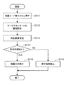
[第2の実施例]
上記第1の実施例においては、ユーザの意志で制限モードへ移行できるようにしている。しかし、これは、ユーザ責任ではあるが、結構なリスクがある。そこで、第2の実施例では、通信部118を介してサービスセンター20に接続し、サービスセンター20側で制限モードへ移行の許否を判断・制御する。
[Second Embodiment]
In the first embodiment, it is possible to shift to the restriction mode at the user's will. However, although this is a user responsibility, there are considerable risks. Thus, in the second embodiment, the
図3及び図4を参照して、本発明の第2の実施例に係るバッテリー108の電源管理方法について説明する。図3は、本実施例に係る電気自動車100側の電源管理処理を示すフローチャートである。図4は、本実施例に係るサービスセンター20側の電源管理処理を示すフローチャートである。
A power management method for the
電気自動車100は、バッテリー108が下限電圧以下でも、第2下限電圧以上で目的地等までに到達できると判定した場合、到達可能である旨をナビゲーションシステム114の表示部等に表示する。そして、図示せぬ制限モード移行ボタンをユーザが押下する(ステップS111)。すると、電気自動車100はサービスセンター20との無線通信を開始する(ステップS112)。
When the
サービスセンター20は、電気自動車100内の情報を取得し、バッテリー108の残量不足を認識する(ステップS121)。また、サービスセンター20は、電気自動車100の位置に関する情報を取得する(ステップS122)。位置情報は、例えば電気自動車100のナビゲーションシステム114から得られる情報である。
The
そして、サービスセンター20は、最寄りの充電場所(例えば目的地又は充電ステーション等)へ、制限付き走行によって到達可能か否かをオペレータ又はコンピュータなどの補助機器が判定する(ステップS123)。その後、サービスセンター20は、判定結果を電気自動車100に送信する(ステップS124)。
Then, the
電気自動車100は判定結果を受信し、ユーザへ音声・表示等で判定結果を通知する(ステップS113)。判定結果が走行許諾であった場合(ステップS114)、電気自動車100はリモート操作等で制限モードに移行され、制限付き走行をする(ステップS115)。一方、判定結果が走行許諾でなかった場合(ステップS114)、電気自動車100は走行が不能となり強制停止のままの状態となる(ステップS116)。
The
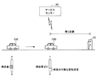
なお、一連の処理の起点は、ユーザが携帯電話で連絡を取り、車体識別番号を通知し(電話番号等の個人情報で確認してもいい)、サービスセンターから電気自動車に通信接続して行うようにしてもよい。このとき、本当に携帯電話で連絡を取っている本人がそこにいるのか判定するため、個人認証技術(自動車搭載、携帯電話搭載)を利用してもよいし、単なる本人確認(住所、誕生日、暗証番号等)で判定してもよい。更には、携帯電話のGPS機能と電気自動車100のナビゲーションシステム114の情報から、同一地点にいることを自動的に判定するようにしてもよい。
The starting point of the series of processes is that the user contacts the mobile phone, notifies the vehicle identification number (can be confirmed by personal information such as a phone number), and communicates with the electric vehicle from the service center. You may do it. At this time, in order to determine whether the person who is actually in contact with the mobile phone is there, you may use personal authentication technology (car mounted, mobile phone mounted), or just identity verification (address, birthday, It may be determined by a personal identification number or the like. Furthermore, it may be determined automatically from the GPS function of the mobile phone and the information of the
なお、制限モードで走行した場合、制限モードに移行して走行したという走行実績をサービスセンター20内に記録してもよい。走行実績は、第1の実施例と同様に、例えば、制限モードによる走行後の自動車整備時に利用できる。
Note that, when traveling in the restriction mode, a travel record indicating that the vehicle has traveled to the restriction mode may be recorded in the
以上、本実施例によれば、ユーザの意志ではなく、サービスセンター20からの指示に基づいて、バッテリー108の使用可能な電圧範囲の変更が許諾されるため、より安全な走行やバッテリー108の使用が可能となる。
As described above, according to the present embodiment, since the change of the usable voltage range of the
[第3の実施例]
次に、図5を参照して、本実施例に係るバッテリー108の電源管理方法について説明する。図5は、本実施例に係る電源管理処理を示すフローチャートである。
[Third embodiment]
Next, a power management method for the
電気自動車100のバッテリー108を家庭用のバッテリーとして利用する場合について説明する。家庭敷地内で電気自動車100をスマートグリッドコンセントに接続して電気自動車100のバッテリー108を家庭用のバッテリーの代わりに使う場合と、電気自動車100のバッテリー108を取り外して家庭用のバッテリーとして利用する場合がある。
A case where the
電気自動車100をスマートグリッドコンセントに接続してバッテリー108を家庭用のバッテリーの代わりに使う場合、例えば家庭内に設置されている電力管理サーバが、通常管理しているバッテリーの他に、電気自動車100のバッテリー108も管理する。ところで、電気自動車100のバッテリー108の上限電圧及び下限電圧は、一般に図7に示すように、使用条件が家庭用のバッテリーに比べて厳しく設定されている。そこで、電気自動車100のバッテリー108が家庭内バッテリーとして使用される際、バッテリー108が使用可能な電圧範囲の限界値を一時的に緩和して、下限電圧以下の電圧で電力を供給することを電力管理サーバに許諾する。
When the
以下、具体的に説明する。まず、電気自動車100が家庭敷地内のスマートグリッドコンセントに接続される(ステップS201)。電気自動車100に使用されているバッテリー108について、電力管理サーバから電気自動車用から家庭用への使用変更の要求があった場合(ステップS202)、バッテリー108は、家庭内での使用という条件で、下限電圧以下の電圧まで供給可能とする許諾をする(ステップS203)。但し、電圧は第2下限電圧を下回らないようにする。また、所定時間下限電圧以下の状態が継続する場合(ステップS204)、バッテリー108は電力管理サーバに対して充電要求を出す(ステップS205)。
This will be specifically described below. First, the
電気自動車100のバッテリー108を取り外して家庭用のバッテリーとして利用する場合、バッテリー108は、例えばユーザ又は電気工事士等によって管理される。そして、バッテリー108の使用可能な電圧範囲は、ユーザ又は電気工事士等によって一時的に緩和されて、バッテリー108が下限電圧以下の電圧で電力を供給できるように変更される。但し、電圧は第2下限電圧を下回らないようにする。
When the
以上、本実施例によれば、バッテリー108を他の目的に使用する場合、使用可能な電圧範囲が変更される。従って、バッテリー108の用途に応じた適切な使用が行われ、バッテリー108を効率良く使用することができる。
As described above, according to this embodiment, when the
[第4の実施例]
次に、図6を参照して、本実施例に係るバッテリー108の電源管理方法について説明する。図6は、本実施例に係る電源管理処理を示すフローチャートである。
[Fourth embodiment]
Next, a power management method for the
家庭内においては、太陽電池等の自然エネルギー発電機器がバッテリー108等と接続される場合がある。自然エネルギー発電機器において電力が発生したとき、家庭内に設置された全てのバッテリーが満充電になっている可能性がある。この場合、電気自動車100のバッテリー108にも充電する。その後、更に発電が行われ、バッテリー108も満充電になった場合、余力のあるバッテリー108に過充電する。
In the home, a natural energy power generation device such as a solar cell may be connected to the
以下、家庭内に設置された全てのバッテリーが満充電になった後の処理を具体的に説明する。まず、太陽光発電等の自然エネルギーを利用した発電によって発生した電力を電気自動車100のバッテリー108に充電する(ステップS301)。充電を継続することによって、バッテリー108が満充電に到達した場合(ステップS302)、上限電圧以上の電圧まで充電を許可するか否かが判断される(ステップS303)。充電を許可しない場合は、充電を停止する(ステップS307)。
Hereinafter, the processing after all the batteries installed in the home are fully charged will be described in detail. First, the
一方、充電を許可する場合、上限電圧以上の電圧まで充電をする過充電を行う(ステップS304)。許諾後、第2上限電圧に到達した場合(ステップS305)は、充電を停止する(ステップS307)。第2上限電圧は、上限電圧より高く、最大充電電圧と同値又は最大充電電圧より低い値である。また、上限電圧以上になっている時間を計測し、電圧が、所定時間以上、上限電圧を上回っていた場合(ステップS306)、充電を停止する(ステップS307)。充電停止後、バッテリー108は電力管理サーバに対して放電要求を出す(ステップS308)。
On the other hand, when charging is permitted, overcharging is performed to charge to a voltage equal to or higher than the upper limit voltage (step S304). If the second upper limit voltage is reached after the permission (step S305), charging is stopped (step S307). The second upper limit voltage is higher than the upper limit voltage and is the same value as the maximum charge voltage or a value lower than the maximum charge voltage. Further, the time when the voltage is equal to or higher than the upper limit voltage is measured, and when the voltage exceeds the upper limit voltage for a predetermined time or longer (step S306), charging is stopped (step S307). After the charging is stopped, the
電力管理サーバが、放電要求に基づいてバッテリー108からの電力を受け取ることができる場合(ステップS309)は、バッテリー108は電力管理サーバへ電力を供給する(ステップS310)。一方、電力管理サーバが電力を受け取ることができない場合(ステップS309)、上限電圧を上回ってからの時間が所定時間以上経過しているか否かを判断する(ステップS311)。上限電圧を上回ってからの時間が所定時間以上経過している場合、バッテリー108は適当な負荷を介して強制放電する(ステップS312)。
When the power management server can receive power from the
バッテリー108は、電力管理サーバを介した放電又は強制放電によって、電圧が上限電圧以下に下がったとき(ステップS313)、バッテリー108は放電を停止し元の状態に復帰する(ステップS314)。上限電圧以上に充電した場合、その充電実績を電力管理サーバ内に記録してもよい。充電実績は、例えば、バッテリー交換の目安等に利用できる。なお、上記例は、電力管理サーバによって電気自動車100のバッテリー108が管理される場合を説明したが、本発明はこの例に限定されない。例えば、電気自動車100のバッテリー108を取り外して家庭用のバッテリーとして利用する場合、バッテリー108は、例えばユーザによって管理される。そして、バッテリー108の使用可能な電圧範囲は、ユーザによって、一時的に緩和されて、上限電圧以上の電圧までバッテリー108に電力を供給できるように変更される。但し、電圧は第2上限電圧を上回らないようにする。
When the voltage drops below the upper limit voltage due to discharge or forced discharge through the power management server (step S313), the
以上、本実施例によれば、バッテリー108は満充電時において過充電を許可する。これにより、自然エネルギー発電によって過剰な電力が発生したとき、その電力を充電できずに破棄する必要がなくなり、電力を無駄にすることが少なくなる。また、過充電した場合でも、所定条件でバッテリー108は強制放電するので、バッテリー108の機能を損傷させることがない。従って、バッテリー108の寿命を延ばしつつ、状況に応じてフレキシブルにバッテリー108を使用することが可能となる。
As described above, according to this embodiment, the
従来、バッテリーの使用可能な電圧範囲について、上限電圧を上回らないように制御したり、下限電圧を下回らないように制御したりしていたが、本実施形態のように、上限電圧や下限電圧を超えた電圧を許諾することはなかった。本実施形態によれば、バッテリーの機能を損傷しない範囲で状況に応じてバッテリーの使用可能な電圧範囲を変更し、バッテリーをより適切に使用することができる。 Conventionally, the voltage range in which the battery can be used has been controlled so as not to exceed the upper limit voltage or not lower than the lower limit voltage. However, as in this embodiment, the upper limit voltage and the lower limit voltage are controlled. There was no permission to exceed the voltage. According to this embodiment, the usable voltage range of the battery can be changed according to the situation within a range where the function of the battery is not damaged, and the battery can be used more appropriately.
以上、添付図面を参照しながら本発明の好適な実施形態について詳細に説明したが、本発明はかかる例に限定されない。本発明の属する技術の分野における通常の知識を有する者であれば、特許請求の範囲に記載された技術的思想の範疇内において、各種の変更例または修正例に想到し得ることは明らかであり、これらについても、当然に本発明の技術的範囲に属するものと了解される。 The preferred embodiments of the present invention have been described in detail above with reference to the accompanying drawings, but the present invention is not limited to such examples. It is obvious that a person having ordinary knowledge in the technical field to which the present invention pertains can come up with various changes or modifications within the scope of the technical idea described in the claims. Of course, it is understood that these also belong to the technical scope of the present invention.
100 電気自動車
102 制御部
104 駆動部
106 バッテリー制御部
108 バッテリー
112 システム処理部
114 ナビゲーションシステム
116 メモリ
118 通信部
122 インバーター
124 充放電管理部
126 バッテリー電圧測定部
128 接続部
DESCRIPTION OF
Claims (16)
前記第一の電圧範囲で充放電がされていて、前記第二の電圧範囲での充放電の許可を受けたとき、前記第二の電圧範囲で充放電がされるように前記バッテリーの設定を一時的に変更する充放電管理部と、
前記バッテリーの現在の電圧を測定する電圧測定部と、
移動体の現在地点から前記バッテリーへの充電可能な地点までの前記移動体の移動に必要な前記バッテリーの必要電力を算出する必要電力算出部と、
を備え、
前記充放電管理部は、
前記現在の電圧と前記必要電力に基づく判定結果に応じて、前記下限電圧以下かつ前記第2下限電圧以上で前記バッテリーが放電されるように前記バッテリーの設定を一時的に変更し、
前記バッテリーの設定を変更した後、前記バッテリーの電圧が前記第一の電圧範囲内の値になったとき、前記バッテリーの充放電が前記第一の電圧範囲でされるように前記バッテリーの設定を復帰する、バッテリー制御装置。 And upper limit voltage and lower limit voltage that defines the first voltage range in which the battery charging and discharging is, defining the wide second voltage range than the first voltage range, lower than the second upper limit voltage and the lower limit voltage first A storage unit for storing two lower limit voltages;
When the battery is charged / discharged in the first voltage range and when permission for charging / discharging in the second voltage range is received, the battery is set to be charged / discharged in the second voltage range. A charge / discharge management unit to temporarily change ;
A voltage measuring unit for measuring a current voltage of the battery;
A required power calculation unit for calculating the required power of the battery necessary for the movement of the mobile body from the current location of the mobile body to a point where the battery can be charged;
Equipped with a,
The charge / discharge management unit
In accordance with a determination result based on the current voltage and the required power, the setting of the battery is temporarily changed so that the battery is discharged at the lower limit voltage or more and the second lower limit voltage or more,
After changing the setting of the battery, when the voltage of the battery becomes a value within the first voltage range, the setting of the battery is performed such that charging / discharging of the battery is performed within the first voltage range. Battery control device to return .
前記充放電管理部は、前記下限電圧以下で前記バッテリーが放電している時間が予め決められた時間以上経過した場合にユーザに対して警告を発する、請求項1に記載のバッテリー制御装置。 When the setting of the battery is temporarily changed, further comprising a time measuring unit for measuring a time during which the battery is discharged below the lower limit voltage,
The battery control device according to claim 1 , wherein the charge / discharge management unit issues a warning to a user when a time during which the battery is discharged at the lower limit voltage or less elapses for a predetermined time or longer.
前記充放電管理部は、前記下限電圧以下で前記バッテリーが放電している時間が予め決められた時間以上経過した場合、前記予め決められた時間以降に前記バッテリーが放電する電流量を低減させる、請求項1に記載のバッテリー制御装置。 When the setting of the battery is temporarily changed, further comprising a time measuring unit for measuring a time during which the battery is discharged below the lower limit voltage,
The charge / discharge management unit reduces the amount of current discharged by the battery after the predetermined time when the time during which the battery is discharged at the lower limit voltage or less has elapsed for a predetermined time or more, The battery control device according to claim 1 .
前記充放電管理部は、前記下限電圧以下で前記バッテリーが放電している時間が予め決められた時間以上経過した場合に、前記現在の電圧が前記第2下限電圧以上でも前記バッテリーからの放電を停止する、請求項1に記載のバッテリー制御装置。 When the setting of the battery is temporarily changed, further comprising a time measuring unit for measuring a time during which the battery is discharged below the lower limit voltage,
The charge / discharge management unit discharges from the battery even when the current voltage is equal to or higher than the second lower limit voltage when a time when the battery is discharged at the lower limit voltage or lower has elapsed for a predetermined time or longer. The battery control device according to claim 1 , wherein the battery control device is stopped.
充放電管理部は、前記現在の電圧に基づく判定結果に応じて、前記上限電圧以上かつ前記第2上限電圧以下で前記バッテリーが充電されるように前記バッテリーの設定を一時的に変更する、請求項1に記載のバッテリー制御装置。 The second upper limit voltage is higher than the upper limit voltage,
Discharge management section, in response to said determination result based on the present voltage, temporarily changes the setting of the battery so that the upper limit voltage or more and the second upper limit voltage the battery below is charged, wherein Item 4. The battery control device according to Item 1 .
前記充放電管理部は、前記上限電圧以上で前記バッテリーが充電している時間が予め決められた時間以上経過した場合に、前記現在の電圧が前記第2上限電圧以下でも前記バッテリーへの充電を停止する、請求項8に記載のバッテリー制御装置。 When the setting of the battery is temporarily changed, further comprising a time measuring unit for measuring the time when the battery is charged at the upper limit voltage or more,
The charge / discharge management unit charges the battery even when the current voltage is equal to or lower than the second upper limit voltage when a time when the battery is charged above the upper limit voltage has elapsed for a predetermined time or longer. The battery control device according to claim 8, which stops.
前記第一の電圧範囲で充放電がされていて、前記第二の電圧範囲での充放電の許可を受けたとき、前記第二の電圧範囲で充放電がされるように前記バッテリーの設定を一時的に変更するステップと、
前記バッテリーの現在の電圧を測定するステップと、
移動体の現在地点から前記バッテリーへの充電可能な地点までの前記移動体の移動に必要な前記バッテリーの必要電力を算出するステップと、
前記現在の電圧と前記必要電力に基づく判定結果に応じて、前記下限電圧以下かつ前記第2下限電圧以上で前記バッテリーが放電されるように前記バッテリーの設定を一時的に変更するステップと、
前記バッテリーの設定を変更した後、前記バッテリーの電圧が前記第一の電圧範囲内の値になったとき、前記バッテリーの充放電が前記第一の電圧範囲でされるように前記バッテリーの設定を復帰するステップと、
を備える、バッテリー制御方法。 And upper limit voltage and lower limit voltage storage unit defining a first voltage range is charged and discharged the battery, defining a wider second voltage range than the first voltage range, the second upper limit voltage and the lower limit voltage Storing a lower second lower limit voltage;
When the battery is charged / discharged in the first voltage range and when permission for charging / discharging in the second voltage range is received, the battery is set to be charged / discharged in the second voltage range. A step to change temporarily ,
Measuring a current voltage of the battery;
Calculating the required power of the battery required for movement of the mobile body from the current location of the mobile body to a point where the battery can be charged;
Temporarily changing the setting of the battery so that the battery is discharged below the lower limit voltage and above the second lower limit voltage according to a determination result based on the current voltage and the required power;
After changing the setting of the battery, when the voltage of the battery becomes a value within the first voltage range, the setting of the battery is performed such that charging / discharging of the battery is performed within the first voltage range. Step to return,
A battery control method comprising:
バッテリーの充放電がされる第一の電圧範囲を規定する上限電圧及び下限電圧と、前記第一の電圧範囲より広い第二の電圧範囲を規定する、第2上限電圧及び前記下限電圧より低い第2下限電圧を記憶する記憶部と、
前記第一の電圧範囲で充放電がされていて、前記第二の電圧範囲での充放電の許可を受けたとき、前記第二の電圧範囲で充放電がされるように前記バッテリーの設定を一時的に変更する充放電管理部と、
前記バッテリーの現在の電圧を測定する電圧測定部と、
移動体の現在地点から前記バッテリーへの充電可能な地点までの前記移動体の移動に必要な前記バッテリーの必要電力を算出する必要電力算出部と、
を備え、
前記充放電管理部は、
前記現在の電圧と前記必要電力に基づく判定結果に応じて、前記下限電圧以下かつ前記第2下限電圧以上で前記バッテリーが放電されるように前記バッテリーの設定を一時的に変更し、
前記バッテリーの設定を変更した後、前記バッテリーの電圧が前記第一の電圧範囲内の値になったとき、前記バッテリーの充放電が前記第一の電圧範囲でされるように前記バッテリーの設定を復帰する、バッテリー制御装置として機能させるためのプログラム。
Computer
And upper limit voltage and lower limit voltage that defines the first voltage range in which the battery charging and discharging is, defining the wide second voltage range than the first voltage range, lower than the second upper limit voltage and the lower limit voltage first A storage unit for storing two lower limit voltages ;
When the battery is charged / discharged in the first voltage range and when permission for charging / discharging in the second voltage range is received, the battery is set to be charged / discharged in the second voltage range. A charge / discharge management unit to temporarily change ;
A voltage measuring unit for measuring a current voltage of the battery;
A required power calculation unit for calculating the required power of the battery necessary for the movement of the mobile body from the current location of the mobile body to a point where the battery can be charged;
Equipped with a,
The charge / discharge management unit
In accordance with a determination result based on the current voltage and the required power, the setting of the battery is temporarily changed so that the battery is discharged at the lower limit voltage or more and the second lower limit voltage or more,
After changing the setting of the battery, when the voltage of the battery becomes a value within the first voltage range, the setting of the battery is performed such that charging / discharging of the battery is performed within the first voltage range. A program for returning and functioning as a battery control device .
Priority Applications (3)
| Application Number | Priority Date | Filing Date | Title |
|---|---|---|---|
| JP2010097916A JP5499872B2 (en) | 2010-04-21 | 2010-04-21 | Battery control device, battery control method and program |
| CN2011100938494A CN102237702A (en) | 2010-04-21 | 2011-04-14 | Battery controller, battery control method and program |
| US13/087,917 US9041355B2 (en) | 2010-04-21 | 2011-04-15 | Battery controller, battery control method and program |
Applications Claiming Priority (1)
| Application Number | Priority Date | Filing Date | Title |
|---|---|---|---|
| JP2010097916A JP5499872B2 (en) | 2010-04-21 | 2010-04-21 | Battery control device, battery control method and program |
Publications (3)
| Publication Number | Publication Date |
|---|---|
| JP2011229306A JP2011229306A (en) | 2011-11-10 |
| JP2011229306A5 JP2011229306A5 (en) | 2013-05-16 |
| JP5499872B2 true JP5499872B2 (en) | 2014-05-21 |
Family
ID=44815257
Family Applications (1)
| Application Number | Title | Priority Date | Filing Date |
|---|---|---|---|
| JP2010097916A Expired - Fee Related JP5499872B2 (en) | 2010-04-21 | 2010-04-21 | Battery control device, battery control method and program |
Country Status (3)
| Country | Link |
|---|---|
| US (1) | US9041355B2 (en) |
| JP (1) | JP5499872B2 (en) |
| CN (1) | CN102237702A (en) |
Families Citing this family (63)
| Publication number | Priority date | Publication date | Assignee | Title |
|---|---|---|---|---|
| JP6073686B2 (en) * | 2010-12-28 | 2017-02-01 | 三洋電機株式会社 | How to detect battery deterioration |
| JP6026535B2 (en) | 2011-07-26 | 2016-11-16 | ゴゴロ インク | RESERVED POWER STORAGE DEVICE DEVICE, METHOD, AND ARTICLE FOR RESERVING A POWER STORAGE DEVICE IN A COLLECTION, CHARGING AND DISTRIBUTION MACHINE |
| US8560147B2 (en) | 2011-07-26 | 2013-10-15 | Gogoro, Inc. | Apparatus, method and article for physical security of power storage devices in vehicles |
| JP6058665B2 (en) | 2011-07-26 | 2017-01-11 | ゴゴロ インク | Apparatus, method and article for collecting, charging and distributing power storage devices such as batteries |
| WO2013016559A2 (en) | 2011-07-26 | 2013-01-31 | Gogoro, Inc. | Apparatus, method and article for a power storage device compartment |
| CN103891088B (en) | 2011-07-26 | 2018-06-26 | 睿能创意公司 | For providing device, the method and article of the information related with the availability of the electrical energy storage at electrical energy storage collection, charging and dispenser |
| CN103843225B (en) | 2011-07-26 | 2018-01-23 | 睿能创意公司 | It is used for the certification of power storage device such as battery etc, the device of safety and control, method and article based on user profiles |
| US9552682B2 (en) | 2011-07-26 | 2017-01-24 | Gogoro Inc. | Apparatus, method and article for redistributing power storage devices, such as batteries, between collection, charging and distribution machines |
| ES2939174T3 (en) | 2011-07-26 | 2023-04-19 | Gogoro Inc | Dynamic limitation of vehicle operation for a better economy of efforts |
| JP6096773B2 (en) | 2011-07-26 | 2017-03-15 | ゴゴロ インク | Apparatus, method, and article for authentication, security, and control of power storage devices such as batteries |
| US10186094B2 (en) | 2011-07-26 | 2019-01-22 | Gogoro Inc. | Apparatus, method and article for providing locations of power storage device collection, charging and distribution machines |
| TWI584976B (en) * | 2011-07-26 | 2017-06-01 | 睿能創意公司 | Dynamically limiting vehicle operation for best effort economy |
| JP5967515B2 (en) * | 2011-11-08 | 2016-08-10 | パナソニックIpマネジメント株式会社 | Power management equipment |
| JP2013115863A (en) * | 2011-11-25 | 2013-06-10 | Honda Motor Co Ltd | Battery management system |
| WO2013094986A1 (en) * | 2011-12-18 | 2013-06-27 | 인포뱅크 주식회사 | Wireless terminal and information processing method of the wireless terminal |
| EP2645527A1 (en) * | 2012-03-26 | 2013-10-02 | Samsung SDI Co., Ltd. | Battery pack |
| JP6343416B2 (en) * | 2012-07-30 | 2018-06-13 | 株式会社東芝 | Battery system |
| WO2014021414A1 (en) * | 2012-08-02 | 2014-02-06 | 日産自動車株式会社 | Battery management system for unpiloted conveyance vehicles |
| US8700258B2 (en) * | 2012-09-12 | 2014-04-15 | GM Global Technology Operations LLC | Park assist system |
| US9216687B2 (en) | 2012-11-16 | 2015-12-22 | Gogoro Inc. | Apparatus, method and article for vehicle turn signals |
| KR102061849B1 (en) * | 2013-01-08 | 2020-01-03 | 삼성디스플레이 주식회사 | Organic light emitting display and method for driving the same |
| US11222485B2 (en) | 2013-03-12 | 2022-01-11 | Gogoro Inc. | Apparatus, method and article for providing information regarding a vehicle via a mobile device |
| US11710105B2 (en) | 2013-03-12 | 2023-07-25 | Gogoro Inc. | Apparatus, method and article for changing portable electrical power storage device exchange plans |
| ES2802906T3 (en) | 2013-03-15 | 2021-01-21 | Gogoro Inc | Modular system for the collection and distribution of electrical storage devices |
| CN105103402B (en) * | 2013-04-11 | 2019-02-22 | 索尼公司 | Battery apparatus |
| KR102182319B1 (en) * | 2013-06-05 | 2020-11-25 | 삼성전자주식회사 | Electronic device and method for providing information of battery in the electronic device |
| US9798371B2 (en) | 2013-06-05 | 2017-10-24 | Samsung Electronics Co., Ltd | Electronic device and content display method thereof |
| CN108189701B (en) | 2013-08-06 | 2021-10-22 | 睿能创意公司 | Electric vehicle system based on thermal profile adjustment of electric energy storage device |
| US9935477B2 (en) * | 2013-08-22 | 2018-04-03 | Hitachi, Ltd. | Charge/discharge control method and charge/discharge control apparatus for lithium ion battery |
| WO2015070057A1 (en) | 2013-11-08 | 2015-05-14 | Gogoro Inc. | Apparatus, method and article for providing vehicle event data |
| JP6629213B2 (en) | 2014-01-23 | 2020-01-15 | ゴゴロ インク | Systems and methods utilizing arrays of power storage devices such as batteries |
| US10228751B2 (en) * | 2014-08-06 | 2019-03-12 | Apple Inc. | Low power mode |
| EP3180821B1 (en) | 2014-08-11 | 2019-02-27 | Gogoro Inc. | Multidirectional electrical connector and plug |
| US9647489B2 (en) | 2014-08-26 | 2017-05-09 | Apple Inc. | Brownout avoidance |
| USD789883S1 (en) | 2014-09-04 | 2017-06-20 | Gogoro Inc. | Collection, charging and distribution device for portable electrical energy storage devices |
| KR102336856B1 (en) * | 2014-11-13 | 2021-12-08 | 삼성전자 주식회사 | Method for Controlling of Charging/Discharging Battery and Electronic Device Using the same |
| CN105846479B (en) * | 2015-01-13 | 2019-01-25 | 葛炽昌 | Communicating battery group and its control method applied to electric vehicle |
| JP6402664B2 (en) * | 2015-03-25 | 2018-10-10 | セイコーエプソン株式会社 | Electronic device and method for initializing control means of electronic device |
| ES2934213T3 (en) | 2015-06-05 | 2023-02-20 | Gogoro Inc | Systems and methods for vehicle load detection and response |
| JP6567362B2 (en) * | 2015-08-12 | 2019-08-28 | 東洋電機製造株式会社 | Power conversion system |
| JP2017063555A (en) * | 2015-09-25 | 2017-03-30 | トヨタ自動車株式会社 | Charger |
| US11180034B2 (en) | 2015-12-04 | 2021-11-23 | Cyberswitchingpatents, Llc | Electric vehicle charging system with priority charging |
| US10850627B2 (en) | 2015-12-04 | 2020-12-01 | Cyberswitchingpatents, Llc | Electric vehicle charging system |
| US11104246B2 (en) * | 2015-12-04 | 2021-08-31 | Cyber Switching Solutions, Inc. | Electric vehicle charging system interface |
| US10843581B2 (en) | 2015-12-04 | 2020-11-24 | Cyberswitchingpatents, Llc | Electric vehicle charging method |
| JP6716279B2 (en) * | 2016-02-15 | 2020-07-01 | キヤノン株式会社 | Electronic device and power control program for electronic device |
| JP6489102B2 (en) * | 2016-12-01 | 2019-03-27 | トヨタ自動車株式会社 | vehicle |
| US10661659B2 (en) | 2017-06-21 | 2020-05-26 | Cyberswitchingpatents, LLC. | Integrated management of electric vehicle charging and non-electric vehicle fueling |
| CN107508304B (en) * | 2017-08-29 | 2020-09-08 | 国电联合动力技术有限公司 | Partition control method of battery energy storage system |
| JP6958287B2 (en) | 2017-11-24 | 2021-11-02 | トヨタ自動車株式会社 | Power control system and vehicle |
| US11363133B1 (en) | 2017-12-20 | 2022-06-14 | Apple Inc. | Battery health-based power management |
| US10817307B1 (en) | 2017-12-20 | 2020-10-27 | Apple Inc. | API behavior modification based on power source health |
| US10599199B1 (en) | 2017-12-20 | 2020-03-24 | Apple Inc. | Systems and methods for power management at device shutdown |
| JP7110594B2 (en) * | 2017-12-26 | 2022-08-02 | トヨタ自動車株式会社 | Electric car |
| JP7003639B2 (en) * | 2017-12-26 | 2022-01-20 | トヨタ自動車株式会社 | Electric car |
| JP6729616B2 (en) * | 2018-03-08 | 2020-07-22 | カシオ計算機株式会社 | Electronic device, power feeding control method, and program |
| CN110045808A (en) * | 2019-04-02 | 2019-07-23 | 惠州Tcl移动通信有限公司 | Capacitances to supply power method, system, storage medium and mobile terminal |
| JP2021033438A (en) * | 2019-08-20 | 2021-03-01 | 本田技研工業株式会社 | Vehicle management system, vehicle management method, and program |
| CN112994131B (en) * | 2019-12-16 | 2024-04-09 | 北京天诚同创电气有限公司 | Battery cluster control system and control method thereof |
| CN111129628B (en) * | 2019-12-23 | 2023-08-15 | 上海电气国轩新能源科技有限公司 | Control method, system, medium and electronic equipment for lithium ion battery cell charge and discharge |
| JP7310654B2 (en) * | 2020-03-02 | 2023-07-19 | 株式会社デンソー | Storage battery control device and program |
| JP2021149331A (en) * | 2020-03-17 | 2021-09-27 | トヨタ自動車株式会社 | Electric power trading system and charging/discharging device for electric vehicle |
| JP7409355B2 (en) | 2021-08-03 | 2024-01-09 | トヨタ自動車株式会社 | electric tractor |
Family Cites Families (17)
| Publication number | Priority date | Publication date | Assignee | Title |
|---|---|---|---|---|
| JPH05205781A (en) * | 1992-01-28 | 1993-08-13 | Sanyo Electric Co Ltd | Over discharge prevention device for battery |
| US6522102B1 (en) * | 2001-12-14 | 2003-02-18 | Zinc Matrix Power, Inc. | Multiple plateau battery charging method and system to charge to the second plateau |
| JP3689084B2 (en) * | 2002-12-11 | 2005-08-31 | 三菱電機株式会社 | Battery charge state calculation device and battery charge state calculation method |
| US6888468B2 (en) * | 2003-01-22 | 2005-05-03 | Midtronics, Inc. | Apparatus and method for protecting a battery from overdischarge |
| US7075269B2 (en) * | 2004-02-25 | 2006-07-11 | Techno Core International Co., Ltd. | Charging equipment for secondary battery |
| JP5001938B2 (en) * | 2005-06-14 | 2012-08-15 | エルジー・ケム・リミテッド | Method and apparatus for adjusting charge or discharge output of battery |
| JP4270309B2 (en) * | 2007-07-18 | 2009-05-27 | トヨタ自動車株式会社 | Electric vehicle and method for charging secondary battery of electric vehicle |
| JP4365429B2 (en) * | 2007-07-24 | 2009-11-18 | トヨタ自動車株式会社 | Navigation device for displaying charging information and vehicle equipped with the device |
| JP4946749B2 (en) * | 2007-09-14 | 2012-06-06 | 三菱自動車工業株式会社 | Vehicle battery control device |
| JP5319903B2 (en) * | 2007-09-18 | 2013-10-16 | 三菱重工業株式会社 | Power storage system |
| JP4882946B2 (en) * | 2007-09-28 | 2012-02-22 | 三菱自動車工業株式会社 | Electricity cost calculation device |
| JP4909863B2 (en) * | 2007-10-04 | 2012-04-04 | 本田技研工業株式会社 | Control device for hybrid vehicle |
| JP2009229112A (en) * | 2008-03-19 | 2009-10-08 | Tdk Corp | Voltage detection circuit |
| US20090313174A1 (en) * | 2008-06-16 | 2009-12-17 | International Business Machines Corporation | Approving Energy Transaction Plans Associated with Electric Vehicles |
| JP4774430B2 (en) * | 2008-09-24 | 2011-09-14 | 本田技研工業株式会社 | Electric vehicle and power storage device control method |
| JP5120204B2 (en) * | 2008-10-28 | 2013-01-16 | アイシン・エィ・ダブリュ株式会社 | Travel guidance device, travel guidance method, and computer program |
| US20100117594A1 (en) * | 2008-11-13 | 2010-05-13 | International Truck Intellectual Property Company, Llc | Strategy for maintaining state of charge of a low-voltage battery bank in a hybrid electric vehicle having a high-voltage traction battery bank |
-
2010
- 2010-04-21 JP JP2010097916A patent/JP5499872B2/en not_active Expired - Fee Related
-
2011
- 2011-04-14 CN CN2011100938494A patent/CN102237702A/en active Pending
- 2011-04-15 US US13/087,917 patent/US9041355B2/en not_active Expired - Fee Related
Also Published As
| Publication number | Publication date |
|---|---|
| CN102237702A (en) | 2011-11-09 |
| US9041355B2 (en) | 2015-05-26 |
| US20110260691A1 (en) | 2011-10-27 |
| JP2011229306A (en) | 2011-11-10 |
Similar Documents
| Publication | Publication Date | Title |
|---|---|---|
| JP5499872B2 (en) | Battery control device, battery control method and program | |
| US9136726B2 (en) | Battery system for movable object and controlling method for the same | |
| CN105705370B (en) | Based on the hot overview regulation electric vehicle system of apparatus for storing electrical energy | |
| US9770996B2 (en) | Systems and methods for powering electric vehicles using a single or multiple power cells | |
| KR102283958B1 (en) | System and method of controling driving for electric vehicle | |
| CN105835710B (en) | Intelligent energy management for extending battery life of electric vehicles | |
| JP5960361B2 (en) | Apparatus and method for controlling charge amount balancing operation of secondary battery cell | |
| KR102368304B1 (en) | Battery pack, method for controlling and driving system of electro-mechanical apparatus having the same | |
| KR20190000445A (en) | Method and apparatus for fast charging and maximum discharging with less-degradation of battery for an electric car | |
| CN111903029B (en) | Method and control unit for monitoring an energy store | |
| JP2011055589A (en) | Power supply system | |
| WO2008053969A1 (en) | Abnormality detecting device for storage element, abnormality detecting method for storage element, abnormality detecting program for storage element, and computer-readable recording medium containing abnormality detecting program for storage element is recorded | |
| JPH07192769A (en) | Secondary battery power storage system | |
| WO2008065910A1 (en) | Accumulator failure detecting device, accumulator failure detecting method, accumulator failure detecting program, and computer-readable recording medium containing the accumulator failure detecting program | |
| KR20210014611A (en) | Charging management device, wireless charging system, server and method for providing wireless charging services | |
| KR101033880B1 (en) | Charge and discharge method for battery of electric vehicle | |
| CN105098276A (en) | Battery systems operable in backup mode and related methods | |
| KR20130126085A (en) | Apparatus and method for balancing of battery cell's charging capacity | |
| US20150251558A1 (en) | Plug-in vehicle eco charging mode | |
| US20120150378A1 (en) | Determination and Usage of Reserve Energy in Stored Energy Systems | |
| KR20140085629A (en) | Battery Life Tracking System | |
| CN104827990A (en) | Vehicle battery system | |
| KR20160132691A (en) | Electric transfer means and the control method thereof | |
| CN111204257A (en) | Charging method for an electrical energy store | |
| JP6305930B2 (en) | Vehicle power supply for regenerative braking |
Legal Events
| Date | Code | Title | Description |
|---|---|---|---|
| A521 | Request for written amendment filed |
Free format text: JAPANESE INTERMEDIATE CODE: A523 Effective date: 20130329 |
|
| A621 | Written request for application examination |
Free format text: JAPANESE INTERMEDIATE CODE: A621 Effective date: 20130329 |
|
| A977 | Report on retrieval |
Free format text: JAPANESE INTERMEDIATE CODE: A971007 Effective date: 20131128 |
|
| A131 | Notification of reasons for refusal |
Free format text: JAPANESE INTERMEDIATE CODE: A131 Effective date: 20131203 |
|
| A521 | Request for written amendment filed |
Free format text: JAPANESE INTERMEDIATE CODE: A523 Effective date: 20140124 |
|
| TRDD | Decision of grant or rejection written | ||
| A01 | Written decision to grant a patent or to grant a registration (utility model) |
Free format text: JAPANESE INTERMEDIATE CODE: A01 Effective date: 20140212 |
|
| A61 | First payment of annual fees (during grant procedure) |
Free format text: JAPANESE INTERMEDIATE CODE: A61 Effective date: 20140225 |
|
| R151 | Written notification of patent or utility model registration |
Ref document number: 5499872 Country of ref document: JP Free format text: JAPANESE INTERMEDIATE CODE: R151 |
|
| R250 | Receipt of annual fees |
Free format text: JAPANESE INTERMEDIATE CODE: R250 |
|
| R250 | Receipt of annual fees |
Free format text: JAPANESE INTERMEDIATE CODE: R250 |
|
| R250 | Receipt of annual fees |
Free format text: JAPANESE INTERMEDIATE CODE: R250 |
|
| R250 | Receipt of annual fees |
Free format text: JAPANESE INTERMEDIATE CODE: R250 |
|
| LAPS | Cancellation because of no payment of annual fees |