JP5498699B2 - Device for measuring deformation characteristics of objects - Google Patents
Device for measuring deformation characteristics of objects Download PDFInfo
- Publication number
- JP5498699B2 JP5498699B2 JP2008539140A JP2008539140A JP5498699B2 JP 5498699 B2 JP5498699 B2 JP 5498699B2 JP 2008539140 A JP2008539140 A JP 2008539140A JP 2008539140 A JP2008539140 A JP 2008539140A JP 5498699 B2 JP5498699 B2 JP 5498699B2
- Authority
- JP
- Japan
- Prior art keywords
- measuring
- corneal
- deformation
- deformation characteristics
- cornea
- Prior art date
- Legal status (The legal status is an assumption and is not a legal conclusion. Google has not performed a legal analysis and makes no representation as to the accuracy of the status listed.)
- Expired - Fee Related
Links
Images


Classifications
-
- A—HUMAN NECESSITIES
- A61—MEDICAL OR VETERINARY SCIENCE; HYGIENE
- A61B—DIAGNOSIS; SURGERY; IDENTIFICATION
- A61B3/00—Apparatus for testing the eyes; Instruments for examining the eyes
- A61B3/10—Objective types, i.e. instruments for examining the eyes independent of the patients' perceptions or reactions
- A61B3/16—Objective types, i.e. instruments for examining the eyes independent of the patients' perceptions or reactions for measuring intraocular pressure, e.g. tonometers
- A61B3/165—Non-contacting tonometers
-
- A—HUMAN NECESSITIES
- A61—MEDICAL OR VETERINARY SCIENCE; HYGIENE
- A61B—DIAGNOSIS; SURGERY; IDENTIFICATION
- A61B3/00—Apparatus for testing the eyes; Instruments for examining the eyes
- A61B3/0008—Apparatus for testing the eyes; Instruments for examining the eyes provided with illuminating means
-
- A—HUMAN NECESSITIES
- A61—MEDICAL OR VETERINARY SCIENCE; HYGIENE
- A61B—DIAGNOSIS; SURGERY; IDENTIFICATION
- A61B3/00—Apparatus for testing the eyes; Instruments for examining the eyes
- A61B3/10—Objective types, i.e. instruments for examining the eyes independent of the patients' perceptions or reactions
- A61B3/107—Objective types, i.e. instruments for examining the eyes independent of the patients' perceptions or reactions for determining the shape or measuring the curvature of the cornea
Landscapes
- Life Sciences & Earth Sciences (AREA)
- Health & Medical Sciences (AREA)
- Medical Informatics (AREA)
- Biophysics (AREA)
- Ophthalmology & Optometry (AREA)
- Engineering & Computer Science (AREA)
- Biomedical Technology (AREA)
- Heart & Thoracic Surgery (AREA)
- Physics & Mathematics (AREA)
- Molecular Biology (AREA)
- Surgery (AREA)
- Animal Behavior & Ethology (AREA)
- General Health & Medical Sciences (AREA)
- Public Health (AREA)
- Veterinary Medicine (AREA)
- Eye Examination Apparatus (AREA)
Description
本発明の実施の形態は、概ね、変形時間(deformation interval)における対象物の表面の変化を通して変形可能な対象物の特性を測定するための方法及び装置に関する。特に、本発明の実施の形態は、生体の角膜の物理的且つ生体力学的特性の測定に関する。 Embodiments of the present invention generally relate to a method and apparatus for measuring a property of a deformable object through a change in the surface of the object at a deformation interval. In particular, embodiments of the present invention relate to the measurement of physical and biomechanical properties of a living cornea.
対象物表面の特性の測定によって、対象物の物理的及び機械的な特性に関する多くの情報が明らかになる。掛けられた力に応じて対象物の表面が変形可能な場合、表面特性の変化を測定することによって、更に有用な情報を提供することができる。測定への関心が多くの分野から寄せられている変形可能な表面を有する多くの有機的及び無機的な対象物が存在する。特に関心がもたれているものとして例示できる対象物は、人の眼の角膜である。物理的、生物学的、光学的及び全ての他の眼に関する特性を理解することに多くの関心があることが、大きな動機付けである。数年にわたって、眼の中でも特に角膜に関して構造上及び動力学的な特性について、異なる理論が提案されてきた。固体物質として角膜をモデル化する初期の理論は、近時、層状の生体動力学的に(biodynamically)応答する構造として角膜を理解する(未だに完全には理解されていない)ことに代わりつつある。 Measuring the surface properties of an object reveals a lot of information about the physical and mechanical properties of the object. If the surface of the object can be deformed in response to the applied force, more useful information can be provided by measuring changes in surface properties. There are many organic and inorganic objects with deformable surfaces that have received interest in measurement from many fields. An object that can be exemplified as being of particular interest is the cornea of a human eye. The great motivation is that there is a lot of interest in understanding the physical, biological, optical and all other eye properties. Over the years, different theories have been proposed for the structural and dynamic properties of the eye, especially with respect to the cornea. Early theories that model the cornea as a solid material have recently been replaced by understanding the cornea as a layered biodynamically responsive structure (not yet fully understood).
角膜の構造及び眼の他のコンポーネントとの相互関係に関する理解は、角膜の種々の局所的(topographical)特性を測定することによって深められてきた。これらの局所的特性は、角膜の湾曲及び参照表面に対する表面の高さを、当該技術分野で知られた他のものと同様に含む。角膜の局所的な測定装置は、トポグラファ、ケラト(角膜)グラファ又はケラト(角膜)メータと称される(トポグラファは、対象物表面の局所的特性を測定するための装置をいう一般的な用語であるのに対して、ケラトグラファ及びケラトメータは、特に角膜の測定に関するものをいう。)。異なる装置は、角膜の種々の局所的特性を決定するために、異なる測定原理を用いる。例えば、一部の装置は、プラシド式反射画像分析を用いる。プラシド式装置は、角膜の湾曲の変数を測定できるが、典型的には直接的に表面の高さを測定することができない。オーブスキャン(Orbscan,登録商標)角膜形状解析装置(ボシュロム社)は、光学的なスリットの走査を利用して局所的な特性を測定する装置である。装置のソフトウェアによって、表面の湾曲と同様に、表面の高さ及び角膜の厚さを直接的に測定することが可能になる。パーテクノロジー社(Par Technology Corporation)によって開発された他の商用装置は、PAR CTS(登録商標)角膜トポグラフィシステム(PAR)として知られている。PAR画像システムは、ラスタ・フォトグラフィー法を用いる。PAR CTS画像システムは、オフセット軸からカメラによって視認される角膜表面に、既知のグリッド形状を投影する。他の局所的特性の測定技術は、共焦点顕微鏡、光コヒーレンス・トモグラフィ、超音波、光干渉法、その他当該技術分野で知られた全てを含む。 An understanding of the structure of the cornea and its interaction with other components of the eye has been deepened by measuring various topographical properties of the cornea. These local characteristics include corneal curvature and surface height relative to the reference surface, as well as others known in the art. A device for locally measuring a cornea is called a topographer, a kerato grapher or a kerato meter (topographer is a general term for a device for measuring a local property of an object surface. In contrast, keratographers and keratometers refer specifically to the measurement of the cornea.) Different devices use different measurement principles to determine various local characteristics of the cornea. For example, some devices use placido reflection image analysis. Placido devices can measure corneal curvature variables, but typically cannot measure surface height directly. An Orbscan (registered trademark) corneal shape analyzer (Bochrom) is a device that measures local characteristics using optical slit scanning. The instrument software makes it possible to directly measure surface height and cornea thickness, as well as surface curvature. Another commercial device developed by Par Technology Corporation is known as the PAR CTS® Corneal Topography System (PAR). The PAR imaging system uses a raster photography method. The PAR CTS imaging system projects a known grid shape onto the corneal surface viewed by the camera from the offset axis. Other local property measurement techniques include confocal microscopy, optical coherence tomography, ultrasound, optical interferometry, and everything else known in the art.
角膜の種々の局所的特性を測定することによって、視覚及び視機能への角膜形状の影響に関する多くの情報を提供することができるが、角膜トポグラフィそれ自体から、構造及び機能を全体的に理解するために必要な、角膜に関する物理的及び生体力学的な特性を明らかにすることができない。角膜の生体力学的及び生体動力学的な特性をよりよく理解するために、角膜の弾性及び粘弾性について知ることが必要である。これらの特性を調査するために用いられる一技術は、既知の力を用いて角膜を変形し、その力に対する角膜の応答を測定することである。この種の例示の装置は、眼圧計として当該技術分野で知られている。眼圧(IOP)を測定するための眼圧計は、本来接触式の装置として開発された。接触式の装置とは、測定中に装置の一部が角膜に接触するように移動させるものである。この種のよく知られた装置は、元々、1950年代に開発されたゴールドマン圧平眼圧器(GAT)である。GATは、角膜として知られた領域を平らにする(「アプラネート」,applanate)ために要求される力を測定し、測定の正確性を評価するために他のタイプの眼圧計と比べた標準として今日使用される。 Measuring various local properties of the cornea can provide a lot of information about the effect of corneal shape on visual and visual function, but from the corneal topography itself, understand the structure and function overall The physical and biomechanical properties of the cornea that are necessary for this cannot be clarified. In order to better understand the biomechanical and biodynamic properties of the cornea, it is necessary to know about the elasticity and viscoelasticity of the cornea. One technique used to investigate these properties is to deform the cornea using a known force and measure the response of the cornea to that force. An exemplary device of this type is known in the art as a tonometer. Tonometers for measuring intraocular pressure (IOP) were originally developed as contact devices. A contact-type device is one in which a part of the device is moved so as to contact the cornea during measurement. A well-known device of this kind is the Goldman Applanation Tonometer (GAT) originally developed in the 1950s. GAT measures the force required to flatten the area known as the cornea ("planate"), and as a standard compared to other types of tonometers to assess the accuracy of the measurement Used today.
GATのような接触眼圧計の場合患者は不快に感じるため、「非接触」眼圧計は開発された。眼圧計は、角膜に圧平を生じさせるために、排出チューブによって、ポンプ機構が生成する空気パルスを方向付けることによって操作する。角膜が流体パルスによって変形すると、光学電気システムは、角膜に斜めに入射するビームからの角膜の反射光を検知することで角膜を観察する。ピーク検知信号は、角膜の反射表面が平らである圧平時に生じる。非接触IOP測定の間、角膜は、実際に元の凸状態から第1状態の圧平を経て僅かに凹状態に変形し、そして空気パルスが消滅するにつれて凹状から第2状態の圧平を経て凸状に戻る。 “Contactless” tonometers have been developed because patients feel uncomfortable with contact tonometers such as GAT. The tonometer operates by directing the air pulses generated by the pump mechanism through the drain tube to create an applanation in the cornea. When the cornea is deformed by a fluid pulse, the optoelectronic system observes the cornea by detecting the reflected light of the cornea from a beam that is incident obliquely on the cornea. The peak detection signal occurs during applanation when the reflective surface of the cornea is flat. During the non-contact IOP measurement, the cornea actually deforms from the original convex state through the first state of applanation to a slightly concave state, and from the concave to the second state of applanation as the air pulse disappears. Return to convex shape.
IOPを測定するための方法及び非接触眼圧計は、米国特許(番号6,419,631及び6,875,175)に開示されており、開示されている内容は、参照によって、適用可能な法令によって許容される全ての範囲で完全に本明細書に組み込まれる。この技術は、商業的にライカート(Reichert;Depew,ニューヨーク)眼応答解析装置(Ocular Response Analyzer)として知られる。http://ocularresponse.reichertoi.comで入手可能な情報によると、ライカート眼応答解析装置は、角膜ヒステリシスと呼ばれる角膜組織を適切に測定するために、動的な双方向の圧平を利用する。角膜ヒステリシスは、測定時間の間における内方へ移動する圧平点及び外方へ移動する圧平点での空気パルスの圧力の違いを参照する(内方への移動は、平らな状態に移動する最初の凸状の角膜形状を参照するが、外方への圧平点は、通常の凸状表面形状に戻る途中の圧平点の方向に移動する、空気パルス後の凹状の角膜表面を参照する。)。角膜のヒステリシスは、繰り返し可能な測定であるため、角膜の種々の状態を特定し且つ分類することに有用な基準を提供する。例えば、角膜ヒステリシスの測定は、角膜の拡張症及びフックスジストロフィのような状態を特定して分類する点で、また緑内障を診察して管理することを補助する点で支援する。異なる角膜の状態のヒステリシス測定との違いは、角膜の生体力学的及び生体動力学的特性に関するより優れた情報にある。角膜のヒステリシス測定は、角膜の生体力学的状態の完全な特性化を提示するために信用されるため、手術結果を予測して制御するだけでなく、屈折矯正手術の対象をスクリーニングする際に、更に潜在的な利用があると思われる。関心のある方は、製造者が提供する更なる情報のために、上述のウェブサイトの記載を参照されたい。 Methods for measuring IOP and non-contact tonometers are disclosed in U.S. Patents (Nos. 6,419,631 and 6,875,175), the contents of which are hereby incorporated by reference. Are fully incorporated herein to the full extent permitted by. This technique is commercially known as Reichert (Depew, NY) Ocular Response Analyzer. According to the information available at http://ocularresponse.reichertoi.com, the Leichart eye response analyzer uses dynamic bilateral applanation to properly measure corneal tissue called corneal hysteresis. Corneal hysteresis refers to the difference in pressure of the air pulse at the applanation point moving inward and the applanation point moving outward during the measurement time (inward movement moves to a flat state) Refer to the first convex corneal shape, the outward applanation point moves in the direction of the applanation point on the way back to the normal convex surface shape, the concave corneal surface after the air pulse refer.). Because corneal hysteresis is a repeatable measurement, it provides a useful reference for identifying and classifying various states of the cornea. For example, the measurement of corneal hysteresis assists in identifying and classifying conditions such as corneal dilatation and Fux dystrophy, and in assisting in diagnosing and managing glaucoma. The difference from the hysteresis measurement of the different corneal states lies in better information regarding the biomechanical and biodynamic properties of the cornea. Corneal hysteresis measurements are trusted to present a complete characterization of the cornea's biomechanical state, so not only predict and control surgical outcomes, but also when screening for refractive surgery subjects There seems to be more potential use. If you are interested, please refer to the description on the website above for further information provided by the manufacturer.
局所的な特性及びヒステリシスのような角膜のパラメータを測定する技術、機能及び装置を記載した上述の観点から、例えば、発明者は、技術の組み合わせ及び他の装置の統合によって、更なる利点を得ることができることを認識してきた。発明者は、更に、角膜の生体力学及び生体動力学に関する理解が深まる結果となる、角膜の特性をより効率的に測定できる新しく改良された方法及び装置の必要性を認識してきた。 In view of the above, which describes techniques, functions and devices for measuring corneal parameters such as local properties and hysteresis, for example, the inventor gains further advantages by combining techniques and integrating other devices. I have realized that I can. The inventor has further recognized the need for new and improved methods and apparatus that can more efficiently measure corneal properties, resulting in a better understanding of corneal biomechanics and biodynamics.
本発明の実施の形態は、概ね、変形可能な対象物表面の変形特性を測定する装置に関する。発明の測定原理は、種々の有機体(例えば、人、動物、又は植物組織)に、また、非接触の力を掛けることによって変形可能な表面を有する有機材料に適用できる。表面は、光が拡散する不透明なものであるか、又は光が拡散しない透明なものである。変形時間の間又はそれを超えて(すなわち、変形時間を通して)、変形可能な対象物表面に関して表面の局所的特性を測定するために適した装置は、変形時間を超えて対象物表面を変形させる非接触の力を掛けることが可能なコンポーネントを組み入れたものであって、特許請求の範囲に記載の発明の範囲に含まれると考えられる。本発明の実施の形態は、トポグラファと、非接触で対象物表面を変形させる装置とを含む変形可能な対象物表面の変形特性を測定する装置に関し、非接触で対象物表面を変形させる装置は、トポグラファと操作上統合されており、また、装置の第1の中心操作軸に沿って配置される。本明細書を通じて使用されるように、「操作上統合された」という語句は、本明細書では、変形力提供装置およびトポグラフィ特性計測装置が同時に操作し、光学経路と(変形および計測)時間とを共有することを意味するものと定義される。言い換えると、各装置は他の装置に依存しており、いずれもが、本発明の実施の形態に係る操作上の相関性のためにスタンド・アロンではない。そのため、添付の特許請求の範囲における「操作上統合された」という用語は、直前に記載した意味に限定される。実施の形態によると、トポグラファは、装置の第2操作軸に沿って配置されたハイスピード・カメラを含む。適切なカメラ又は検知器は、変形時間の間に、特定の変形事象に関する連続画像又は静止画像を捉えられることが要求される。装置は、装置の第3操作軸に沿って配置された、グリッド対象物及びグリッド画像を投影するための光源を含む光学システムをも含む。特定の形態において、少なくとも1つの第2及び第3軸は、第1軸からオフセットしている。更に、軸の全てが独立した方向であってよい。
Embodiments of the present invention generally relates to equipment for measuring the deformation characteristics of the deformable surface of the object. The measurement principles of the invention can be applied to various organic organisms (eg, human, animal, or plant tissue) and to organic materials having surfaces that can be deformed by applying non-contact forces. The surface is opaque where light diffuses or is transparent where light does not diffuse. An apparatus suitable for measuring a local property of a surface with respect to a deformable object surface during or beyond the deformation time (ie throughout the deformation time) deforms the object surface beyond the deformation time It incorporates components capable of applying a non-contact force and is considered to be within the scope of the claimed invention. Embodiments of the present invention relate to an apparatus for measuring deformation characteristics of a deformable object surface including a topographer and an apparatus that deforms the object surface in a non-contact manner. , Which is operably integrated with the topographer and arranged along the first central operating axis of the device. As used throughout this specification, the phrase “operationally integrated” is used herein to refer to the optical path, (deformation and measurement) time, and the deformation force providing device and the topographic property measurement device operating simultaneously. Defined to mean sharing. In other words, each device is dependent on other devices, and none are stand alone due to operational correlation according to embodiments of the present invention. As such, the term “operably integrated” in the appended claims is limited to the meaning just described. According to an embodiment, the topographer includes a high-speed camera arranged along the second operating axis of the device. A suitable camera or detector is required to be able to capture a continuous or still image for a particular deformation event during the deformation time. The apparatus also includes an optical system that includes a light source for projecting a grid object and a grid image disposed along a third operating axis of the apparatus. In a particular form, the at least one second and third axis is offset from the first axis. Furthermore, all of the axes may be in independent directions.
対象物が生体の眼の角膜である形態に関して、トポグラファは、好適には、コンピュータ支援のビデオ角膜画像に基づくトポグラファ(本明細書では角膜トポグラファともいう。)である。特別な形態において、角膜トポグラファは、改良されたPAR CTS画像装置である。ある形態によると、非接触で対象物表面を変形する装置は、空気の圧力パルスに基づく装置である。特別な形態において、非接触で対象物表面を変形する装置は、非接触眼圧計である。 With respect to the form in which the object is a cornea of a living eye, the topographer is preferably a topographer based on computer-assisted video corneal images (also referred to herein as a corneal topographer). In a special form, the corneal topographer is an improved PAR CTS imager. According to one form, the device that deforms the surface of the object in a non-contact manner is a device based on pressure pulses of air. In a special form, the device that deforms the surface of the object in a non-contact manner is a non-contact tonometer.
変形可能な対象物表面の変形特性を測定する方法に関する実施の形態によると、装置は、対象物表面の局所的特性の測定を行うトポグラファと、装置が備える非接触で力を生成するコンポーネントとを含む。測定されるべき対象物表面は、装置に関連づけて適切に配置される。対象物表面は、力を掛けられると、変形時間を超えてそれに応じた変形をする。複数の、生体の局所的特性の測定は、変形時間の間になされる。局所的特性の測定は、例えば、表面の湾曲、表面の高さ、表面の窪み、表面の変形の対称性、表面の変形の形状、表面の変形領域、表面の変形のヒステリシス並びに弾性、粘性及び圧力を(これらに限定されるものではないが)含む。
According to an embodiment relating to a method for measuring a deformation characteristic of a deformable object surface, the apparatus comprises a topographer for measuring a local characteristic of the object surface and a non-contact force-generating component provided in the apparatus. Including. The object surface to be measured is appropriately arranged in relation to the device. When a force is applied to the surface of the object, the object surface is deformed in accordance with the deformation time. A plurality of measurements of local characteristics of the living body are made during the deformation time. Local property measurements include, for example, surface curvature, surface height, surface depression, surface deformation symmetry, surface deformation shape, surface deformation area, surface deformation hysteresis and elasticity, viscosity and Pressure (including but not limited to).
例示される特に有用な本発明の実施の形態は、角膜の変形特性を測定するための装置に関する。装置は、角膜トポグラファと、角膜トポグラファと操作上統合された非接触眼圧計とを含む。特に有用な形態において、角膜トポグラファは、ラスタ立体画像に基づくトポグラファである。更に特に、角膜トポグラファは、改良されたPAR CTS画像装置である。 The particularly useful embodiment of the invention illustrated relates to an apparatus for measuring the deformation characteristics of the cornea. The apparatus includes a corneal topographer and a non-contact tonometer that is operably integrated with the corneal topographer. In a particularly useful form, the corneal topographer is a topographer based on raster stereo images. More particularly, the corneal topographer is an improved PAR CTS imager.
上述の装置を使用することによって、角膜の変形特性を測定するための方法が可能になる。上に挙げた測定可能な変形特性に加えて、屈折力、眼圧、角膜ヒステリシス、角膜弾性、角膜粘性及び種々の角膜局所的な既知の特性が、測定され得る。 By using the apparatus described above, a method for measuring the deformation characteristics of the cornea is possible. In addition to the measurable deformation characteristics listed above, refractive power, intraocular pressure, corneal hysteresis, corneal elasticity, corneal viscosity and various corneal local known properties can be measured.
本発明の更に他の特徴及び有用性は、後述の詳細な説明で記載されているものであり、部分的には、その記載内容から、又は添付の図面だけでなく特許請求の範囲を含む本明細書に記載の本発明を実施することによって認識される内容から、当業者に明らかであろう。 Additional features and utilities of the present invention will be set forth in the detailed description which follows, and in part from the description or from the appended drawings. It will be apparent to those skilled in the art from the content recognized by practicing the invention described herein.
上述の概要及び後述の詳細な説明は、本発明の例示に過ぎない。それは、特許請求の範囲に記載された本発明の本質及び特徴を理解するための概観及びフレームワークを提供するものである。添付の図面は、本発明に関する更なる理解を可能にし、本明細書に組み入れられ且つその一部を構成する。図は、発明の種々の実施の形態を示しており、説明とともに本発明の原理及び操作の説明に参照される。 The above summary and the following detailed description are merely illustrative of the invention. It provides an overview and framework for understanding the nature and characteristics of the claimed invention. The accompanying drawings enable further understanding of the invention and are incorporated in and constitute a part of this specification. The figures illustrate various embodiments of the invention and together with the description refer to the description of the principles and operations of the invention.
本発明の実施の形態は、概ね、変形可能な対象物表面に関する変形特性を測定するための装置に関する。本発明の実施の形態は、図1に示すように、生体の角膜の変形特性を測定するための装置10に関する。可能な限り、同じ又は同様の部分を参照する全図に関して、同一の参照番号が使用される。装置10は、操作上また物理的に統合された装置のコンポーネントである角膜トポグラファ(topographer)20及び眼圧計30を含む。
Embodiments of the present invention generally relate to an apparatus for measuring deformation characteristics associated with a deformable object surface. The embodiment of the present invention relates to an
図1に示す装置の角膜トポグラファ20は、PAR(posterior apical radius) CTS 角膜解剖システムの後にモデル化されたトポグラファに基づくラスタ立体画像である。そのようなシステムは、米国特許(番号4,995,716;5,159,361)に開示されており、これらの明細書の開示は、参照によって、全体を説明した場合のように、全体的に可能な限りの広さで本明細書に組み入れられる。角膜トポログラファ20は、装置10の第2操作軸76に沿って配置されたハイスピード・カメラ/検出器32と、グリッド44及び光源45を含み、装置10の第3操作軸78に沿って配置されるグリッド像を投影するための光学システム42とを含む。本実施の形態では眼88の角膜87である対象物は、点線98によって図示される測定平面において、中央装置軸82に沿って配置される。PAR CTS 角膜トポグラファ20のコンポーネントである種々のレンズ及びフィルタは、図示されない。
The
例示の装置10は、第1操作軸72に沿って配置される非接触眼圧計52をも含む。軸72及び軸82は、同一平面上にある。第2及び第3操作軸76,78は、このようにオフセットしている。例示の形態において、非接触眼圧計52は、ライカート眼応答解析装置であり、上述の米国特許番号6,419,631及び6,875,175に説明されている。一旦、角膜が適切に測定平面98に位置付けられると、所定量の空気パルスが角膜に向けて排出されることで、測定が開始する。空気パルスが角膜に伝える衝撃エネルギーによって、角膜はその元の凸状態から、第1状態の圧平P1を経て、凹状態に可逆的に変形する。ポンプソレノイドを断つことによって空気パルスが減衰し又は制御可能に減退すると、角膜は凹状態から、第2状態の圧平P2を経て、元の凸状態に戻る。この変形は、図3で参照された変形時間Tで生じる。図2A及び2Bは、測定時間の間で(図2Aの)第1圧平の時点(t1)と(図2Bの)第2圧平の時点(t2)との角膜Cに作用する力を示す簡単な略図であり、動力学的な影響を無視している。図において、F1は、入射する空気パルスの内側方向に向けた力を示し、F2は、角膜組織自体を湾曲させるために必要な力を示し、F3は、眼圧に寄与する外側方向に向けた力を示す。
The
眼応答解析装置の操作原理に基づき、角膜トポグラファ20は、複数の変形特性の測定を取得するために、変形時間Tを超えて、時刻t1での事象P1、時刻t2での事象P2、最大プレナム(plenum)圧、及び/又は、任意の予め決めたトリガーポイントから、タイミングよく開始できる。
Based on the operating principle of the eye response analyzer, the
例示する装置の実施の形態によると、PAR CTSシステムの使用は、ハイスピード・カメラ/検出器を組み込むために改良され、それによって、カメラ32及び光学システム42のオフセット軸76,78が眼圧計52の中心位置を備えるため、装置10の角膜トポグラファ20は好都合である。プラシド式トポグラファによると、眼圧計を中心に位置付けることはできないが、他の局所的な特性を測定する装置は、装置10に使用されるべき適切な物理的配置を備えてもよい。
According to the illustrated apparatus embodiment, the use of the PAR CTS system is improved to incorporate a high speed camera / detector, whereby the offset axes 76, 78 of the
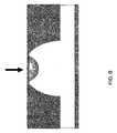
図4及び5は、それぞれ、空気をひと吹きした角膜表面の変形の前後をシミュレートしたPAR CTSグリッド画像を示す。図6は、図5に対応する広くて浅い角膜の窪みを示す。図で比較するため、図7は、図6に示されるものより、狭くて深い角膜の窪みを示す。図は、より軟らかい又はより硬い角膜が掛けられた変形力に応じて異なる反応をすることを示す。 4 and 5 show PAR CTS grid images simulating before and after deformation of the corneal surface blown with air, respectively. FIG. 6 shows a wide and shallow corneal depression corresponding to FIG. For comparison in the figure, FIG. 7 shows a narrower and deeper corneal depression than that shown in FIG. The figure shows that the softer or harder cornea responds differently depending on the deformation force applied.
種々の変形特性は、上述の装置の実施の形態を用いて測定され得る。例えば、表面変形の規模、対称又は非対称、形状及び領域は、圧平深さ、角膜の湾曲、高さ(elevation)、ヒステリシス、角膜の柔軟度及び摩擦、並びに、IOP(Intraocular Pressure)と同様に、変形時間の間に測定される。 Various deformation characteristics can be measured using the above-described apparatus embodiments. For example, surface deformation magnitude, symmetry or asymmetric, shape and area can be similar to applanation depth, corneal curvature, elevation, hysteresis, corneal flexibility and friction, and IOP (Intramolecular Pressure). , Measured during deformation time.
本発明の精神及び範囲から逸脱することなく、種々の改良及び変形が本発明になされ得ることは、当業者に明らかである。このように、本発明の改良及び変形が添付の特許請求の範囲に係る請求項及びそれらと均等なものの範囲に含まれる場合、本発明はそれらを包含する。 It will be apparent to those skilled in the art that various modifications and variations can be made to the present invention without departing from the spirit and scope of the invention. Thus, it is intended that the present invention covers the modifications and variations of this invention provided they come within the scope of the appended claims and their equivalents.
Claims (8)
角膜トポグラフィック特性測定装置と、
非接触の変形力提供装置とを備え、
上記角膜トポグラフィック特性測定装置と、非接触の変形力提供装置とは、同時に操作するために操作上統合されており、
上記非接触の変形力提供装置は、上記変形特性を測定する装置の第1の軸線に沿って配置され、
上記角膜トポグラフィック特性測定装置は、上記変形特性を測定する装置の第2の軸線に沿って配置された単一のカメラと、上記変形特性を測定する装置の第3の軸線に沿って配置された、上記生体角膜の表面を覆ってグリッド像を投影するためのグリッド対象物及び光源を含む光学システムとを備えており、
上記第1,第2及び第3の軸線は全て独立した方向を指向し、上記第1の軸線は、上記第2の軸線と上記第3の軸線の中間に位置しており、
上記変形特性を測定する装置で測定された変形特性に基づいて、上記グリッド像で覆われた上記生体角膜の表面について角膜弾性および角膜粘性の少なくとも何れか一方が測定される、
ことを特徴とする変形特性を測定する装置。 An apparatus for measuring the deformation characteristics of a biological cornea through deformation time,
A corneal topographic characteristic measuring device;
A non-contact deformation force providing device,
And the corneal topographic characteristic measuring device, the deformation force providing unit of the non-contact, are operationally integrated to operate simultaneously,
The non-contact deformation force providing device is disposed along a first axis of the device for measuring the deformation characteristics;
The corneal topographic characteristic measuring device is arranged along a single camera arranged along the second axis of the device for measuring the deformation characteristics and a third axis of the device for measuring the deformation characteristics. An optical system including a grid object and a light source for projecting a grid image covering the surface of the biological cornea,
The first, second, and third axes are all directed in independent directions, and the first axis is located between the second axis and the third axis,
Based on the deformation characteristics measured by the apparatus for measuring the deformation characteristics, at least one of corneal elasticity and corneal viscosity is measured for the surface of the biological cornea covered with the grid image.
A device for measuring deformation characteristics.
Applications Claiming Priority (3)
| Application Number | Priority Date | Filing Date | Title |
|---|---|---|---|
| US73175605P | 2005-10-31 | 2005-10-31 | |
| US60/731,756 | 2005-10-31 | ||
| PCT/US2006/060381 WO2007053826A2 (en) | 2005-10-31 | 2006-10-31 | Method and apparatus for measuring the deformation characteristics of an object |
Publications (3)
| Publication Number | Publication Date |
|---|---|
| JP2009513313A JP2009513313A (en) | 2009-04-02 |
| JP2009513313A5 JP2009513313A5 (en) | 2013-09-05 |
| JP5498699B2 true JP5498699B2 (en) | 2014-05-21 |
Family
ID=38006545
Family Applications (1)
| Application Number | Title | Priority Date | Filing Date |
|---|---|---|---|
| JP2008539140A Expired - Fee Related JP5498699B2 (en) | 2005-10-31 | 2006-10-31 | Device for measuring deformation characteristics of objects |
Country Status (8)
| Country | Link |
|---|---|
| US (1) | US9364148B2 (en) |
| EP (1) | EP1942787B1 (en) |
| JP (1) | JP5498699B2 (en) |
| CN (1) | CN101299957B (en) |
| BR (1) | BRPI0618066A2 (en) |
| CA (1) | CA2621719C (en) |
| HK (1) | HK1124508A1 (en) |
| WO (1) | WO2007053826A2 (en) |
Families Citing this family (34)
| Publication number | Priority date | Publication date | Assignee | Title |
|---|---|---|---|---|
| CN101299957B (en) | 2005-10-31 | 2011-06-22 | Crs合伙公司 | Method and apparatus for measuring the deformation characteristics of an object |
| US8226235B2 (en) * | 2006-02-14 | 2012-07-24 | Vision Optimization, Llc | Method and apparatus for determining dynamic deformation characteristics of an object |
| US8574277B2 (en) | 2009-10-21 | 2013-11-05 | Avedro Inc. | Eye therapy |
| JP6377906B2 (en) | 2010-03-19 | 2018-08-22 | アヴェドロ・インコーポレーテッドAvedro,Inc. | System for applying and monitoring eye treatment |
| US9693728B2 (en) * | 2010-06-29 | 2017-07-04 | Lucidux, Llc | Systems and methods for measuring mechanical properties of deformable materials |
| JP2012152469A (en) * | 2011-01-27 | 2012-08-16 | Nidek Co Ltd | Ophthalmic surgical microscope |
| TWI450706B (en) * | 2011-04-14 | 2014-09-01 | Crystalvue Medical Corp | Intraocular pressure detecting device and detecting method thereof |
| US9044308B2 (en) | 2011-05-24 | 2015-06-02 | Avedro, Inc. | Systems and methods for reshaping an eye feature |
| DE102011076793A1 (en) * | 2011-05-31 | 2012-12-06 | Oculus Optikgeräte GmbH | Ophthalmological analysis method and analysis system |
| EP2713849B1 (en) | 2011-06-02 | 2017-02-15 | Avedro, Inc. | Systems for monitoring time based photo active agent delivery or photo active marker presence |
| WO2012163080A1 (en) * | 2011-06-03 | 2012-12-06 | The Hong Kong University Of Science And Technology | Non-destructive measurement of mechanical properties of an ellipsoidal shell |
| US20130102921A1 (en) | 2011-10-20 | 2013-04-25 | Alain Saurer | Method and device for monitoring biomechanical properties of the eye |
| EP4074294A1 (en) | 2012-07-16 | 2022-10-19 | Avedro, Inc. | Systems and methods for corneal cross-linking with pulsed light |
| CN103278131B (en) * | 2013-05-10 | 2015-09-30 | 东北大学 | A kind of axial deformation of rock sample measuring method |
| US9498114B2 (en) | 2013-06-18 | 2016-11-22 | Avedro, Inc. | Systems and methods for determining biomechanical properties of the eye for applying treatment |
| WO2014205145A1 (en) * | 2013-06-18 | 2014-12-24 | Avedro, Inc. | Systems and methods for determining biomechanical properties of the eye for applying treatment |
| WO2016069628A1 (en) | 2014-10-27 | 2016-05-06 | Avedro, Inc. | Systems and methods for cross-linking treatments of an eye |
| US10114205B2 (en) | 2014-11-13 | 2018-10-30 | Avedro, Inc. | Multipass virtually imaged phased array etalon |
| CN104502269B (en) * | 2014-12-17 | 2017-01-11 | 温州职业技术学院 | Mechanical property parameter detection device of in-vitro cornea |
| EP3827792A1 (en) | 2015-04-24 | 2021-06-02 | Avedro, Inc. | Systems and methods for photoactivating a photosensitizer applied to an eye |
| US10028657B2 (en) | 2015-05-22 | 2018-07-24 | Avedro, Inc. | Systems and methods for monitoring cross-linking activity for corneal treatments |
| CN108025011A (en) | 2015-07-21 | 2018-05-11 | 艾维德洛公司 | With the system and method for photosensitizing agents eyes |
| TW201703722A (en) * | 2015-07-21 | 2017-02-01 | 明達醫學科技股份有限公司 | Measurement apparatus and operating method thereof |
| CN105167805A (en) * | 2015-08-19 | 2015-12-23 | 深圳市亿领科技有限公司 | Cornea elasticity measurement method and cornea elasticity measurement device |
| TWI568408B (en) * | 2015-12-23 | 2017-02-01 | 財團法人工業技術研究院 | Intraocular pressure detecting device and detecting method thereof |
| US10568515B2 (en) | 2016-06-21 | 2020-02-25 | Otonexus Medical Technologies, Inc. | Optical coherence tomography device for otitis media |
| US10357161B1 (en) | 2017-05-31 | 2019-07-23 | Otonexus Medical Technologies, Inc. | Infrared otoscope for characterization of effusion |
| WO2017223341A1 (en) * | 2016-06-22 | 2017-12-28 | University Of Houston System | System and method for measuring intraocular pressure and ocular tissue biomechanical properties |
| EP3568058A4 (en) | 2017-01-11 | 2020-11-11 | Avedro, Inc. | Systems and methods for determining cross-linking distribution in a cornea and/or structural characteristics of a cornea |
| CN108346472A (en) * | 2017-01-24 | 2018-07-31 | 阿格斯医材公司 | Cornea operation risk appraisal procedure and its system |
| EP4142284A1 (en) * | 2017-03-06 | 2023-03-01 | Gelsight, Inc. | Surface topography measurement systems |
| WO2019173762A1 (en) | 2018-03-08 | 2019-09-12 | Avedro, Inc. | Micro-devices for treatment of an eye |
| CN109030212A (en) * | 2018-08-02 | 2018-12-18 | 西安建筑科技大学 | A kind of air-supported membrane structure corner Deformation Observation experimental rig |
| US11642244B2 (en) | 2019-08-06 | 2023-05-09 | Avedro, Inc. | Photoactivation systems and methods for corneal cross-linking treatments |
Family Cites Families (30)
| Publication number | Priority date | Publication date | Assignee | Title |
|---|---|---|---|---|
| US3585849A (en) * | 1968-10-09 | 1971-06-22 | American Optical Corp | Method and apparatus for measuring intraocular pressure |
| US4621644A (en) * | 1984-04-13 | 1986-11-11 | George J. Eilers | Automatic applanation tonometer |
| US4812448A (en) * | 1984-10-22 | 1989-03-14 | Knepper Paul A | Method for the prevention of ocular hypertension, treatment of glaucoma and treatment of ocular hypertension |
| JPH01195839A (en) * | 1988-02-01 | 1989-08-07 | Topcon Corp | Ophthalmologic instrument |
| JPH02121621A (en) * | 1988-11-01 | 1990-05-09 | Topcon Corp | Ophthalmic machine |
| US5033841A (en) * | 1988-11-01 | 1991-07-23 | Kabushiki Kaisha Topcon | Ophthalmological instrument |
| US4995716A (en) * | 1989-03-09 | 1991-02-26 | Par Technology Corporation | Method and apparatus for obtaining the topography of an object |
| US5159361A (en) * | 1989-03-09 | 1992-10-27 | Par Technology Corporation | Method and apparatus for obtaining the topography of an object |
| JP3168014B2 (en) * | 1991-01-30 | 2001-05-21 | 株式会社ニデック | Non-contact tonometer |
| US5474066A (en) * | 1994-01-31 | 1995-12-12 | Leica Inc. | Non-contact tonometer |
| US6149609A (en) * | 1995-10-18 | 2000-11-21 | Scientific Optics, Inc. | Method and apparatus for improving vision |
| JPH10309265A (en) * | 1997-05-12 | 1998-11-24 | Konan:Kk | Ophthalmic imaging device |
| CN2317809Y (en) * | 1997-10-09 | 1999-05-12 | 深圳市医用电子仪器厂 | Eyeball-cornea topographical instrument |
| JP3695949B2 (en) * | 1998-07-01 | 2005-09-14 | 株式会社ニデック | Non-contact tonometer |
| ATE236568T1 (en) * | 1998-11-13 | 2003-04-15 | Benedikt Prof Dr Med Jean | METHOD AND DEVICE FOR SIMULTANEOUS DETECTION OF THE SURFACE TOPOGRAPHY AND THE BIOMETRY OF AN EYE |
| JP2000254101A (en) * | 1999-01-06 | 2000-09-19 | Konan Inc | Ophthalmological examination device |
| US6045503A (en) * | 1999-01-20 | 2000-04-04 | Kamilllo Eisner-Stiftung | Method of and apparatus for determining the topology of a cornea |
| FR2798744B1 (en) * | 1999-09-22 | 2002-04-05 | Essilor Int | METHOD FOR DETERMINING THE SHAPE OF AN OPHTHALMIC CONTACT LENS FOR CORRECTING OPTICAL ABERRATIONS OF THE EYE BEYOND DEFOCUSING OR ASTIGMATISM AND DEVICE FOR IMPLEMENTING THIS METHOD |
| US20020077797A1 (en) * | 2000-12-18 | 2002-06-20 | Hall Gary W. | Method and apparatus for automated simulation and design of corneal refractive procedures |
| US6875175B2 (en) * | 2002-07-01 | 2005-04-05 | Reichert, Inc. | Duel mode non-contact tonometer |
| US7004902B2 (en) * | 2003-03-21 | 2006-02-28 | Reichert, Inc. | Method and apparatus for measuring biomechanical characteristics of corneal tissue |
| US7204806B2 (en) * | 2003-06-17 | 2007-04-17 | Mitsugu Shimmyo | Method and apparatus for obtaining corrected intraocular pressure values |
| CN2649051Y (en) * | 2003-10-24 | 2004-10-20 | 黄长征 | Artificial crystalline surgical information detecting system |
| US7425067B2 (en) * | 2003-11-14 | 2008-09-16 | Ophthonix, Inc. | Ophthalmic diagnostic instrument |
| US7871378B1 (en) * | 2004-12-22 | 2011-01-18 | Achevé Technology, Inc. | Device and method to measure corneal biomechanical properties and its application to intraocular pressure measurement |
| DE202005002562U1 (en) * | 2005-02-16 | 2005-06-09 | Oculus Optikgeräte GmbH | Ophthalmic analysis system for measuring intraocular pressure in the eye |
| US7798962B2 (en) * | 2005-09-08 | 2010-09-21 | Reichert, Inc. | Method and apparatus for measuring corneal resistance |
| CN101299957B (en) | 2005-10-31 | 2011-06-22 | Crs合伙公司 | Method and apparatus for measuring the deformation characteristics of an object |
| JP5028057B2 (en) * | 2005-11-01 | 2012-09-19 | 株式会社ニデック | Ophthalmic equipment |
| JP4426552B2 (en) * | 2006-09-20 | 2010-03-03 | 株式会社トプコン | Non-contact tonometer |
-
2006
- 2006-10-31 CN CN2006800407098A patent/CN101299957B/en not_active Expired - Fee Related
- 2006-10-31 EP EP06839630.8A patent/EP1942787B1/en active Active
- 2006-10-31 CA CA2621719A patent/CA2621719C/en not_active Expired - Fee Related
- 2006-10-31 WO PCT/US2006/060381 patent/WO2007053826A2/en active Application Filing
- 2006-10-31 US US12/091,307 patent/US9364148B2/en active Active
- 2006-10-31 JP JP2008539140A patent/JP5498699B2/en not_active Expired - Fee Related
- 2006-10-31 BR BRPI0618066-3A patent/BRPI0618066A2/en not_active Application Discontinuation
-
2009
- 2009-04-29 HK HK09103956.7A patent/HK1124508A1/en not_active IP Right Cessation
Also Published As
| Publication number | Publication date |
|---|---|
| CN101299957A (en) | 2008-11-05 |
| BRPI0618066A2 (en) | 2011-08-16 |
| WO2007053826A2 (en) | 2007-05-10 |
| EP1942787B1 (en) | 2016-07-06 |
| EP1942787A4 (en) | 2010-12-22 |
| JP2009513313A (en) | 2009-04-02 |
| HK1124508A1 (en) | 2009-07-17 |
| EP1942787A2 (en) | 2008-07-16 |
| US9364148B2 (en) | 2016-06-14 |
| WO2007053826A3 (en) | 2007-11-08 |
| CA2621719C (en) | 2014-05-20 |
| US20080259276A1 (en) | 2008-10-23 |
| CA2621719A1 (en) | 2007-05-10 |
| CN101299957B (en) | 2011-06-22 |
Similar Documents
| Publication | Publication Date | Title |
|---|---|---|
| JP5498699B2 (en) | Device for measuring deformation characteristics of objects | |
| AU2017357045B2 (en) | Optical coherence tomography systems and methods with dispersion compensation | |
| Zeimer et al. | Feasibility test of a new method to measure retinal thickness noninvasively. | |
| US7871378B1 (en) | Device and method to measure corneal biomechanical properties and its application to intraocular pressure measurement | |
| US20060241367A1 (en) | Ophthalmic analysis system for measuring the intraocular pressure in the eye | |
| US11751763B2 (en) | Method and system for pupil retro illumination using sample arm of OCT interferometer | |
| JP2014530086A (en) | Method and apparatus for identifying eye topography | |
| KR20050116383A (en) | Moire aberrometer | |
| JP2021525578A (en) | Devices and methods for in vivo measurement of corneal biomechanical responses | |
| JP2008011878A (en) | Ophthalmologic apparatus | |
| JP3539813B2 (en) | Ophthalmic equipment | |
| CN105167805A (en) | Cornea elasticity measurement method and cornea elasticity measurement device | |
| US11013407B2 (en) | Intraocular pressure measurement for an eye docked to a laser system | |
| US5680196A (en) | Position detecting apparatus for an ophthalmologic apparatus | |
| EP3714765B1 (en) | Device and method for obtaining mechanical, geometric, and dynamic measurements of optical surfaces | |
| US11896306B2 (en) | Optical measurement systems and processes with non-telecentric projection of fixation target to eye | |
| JP2019058486A (en) | Eye measurement apparatus and method | |
| Reisdorf | 6. Measuring biomechanical properties in vivo: the Corvis® ST | |
| Jȩdzierowska et al. | Imaging of the anterior eye segment in the evaluation of corneal dynamics | |
| WO2022209991A1 (en) | Ophthalmologic device | |
| Bergeles et al. | On imaging and localizing untethered intraocular devices with a stationary camera | |
| US10806342B2 (en) | Determination of continuous dynamic corneal viscoelastic bending moduli | |
| JP2022157346A (en) | Ophthalmologic apparatus and ophthalmology program | |
| JP2022157345A (en) | Ophthalmologic apparatus | |
| Glass | Characterization of the biomechanical properties of the in vivo human cornea |
Legal Events
| Date | Code | Title | Description |
|---|---|---|---|
| A521 | Request for written amendment filed |
Free format text: JAPANESE INTERMEDIATE CODE: A523 Effective date: 20091030 |
|
| A621 | Written request for application examination |
Free format text: JAPANESE INTERMEDIATE CODE: A621 Effective date: 20091030 |
|
| A131 | Notification of reasons for refusal |
Free format text: JAPANESE INTERMEDIATE CODE: A131 Effective date: 20111213 |
|
| A601 | Written request for extension of time |
Free format text: JAPANESE INTERMEDIATE CODE: A601 Effective date: 20120312 |
|
| A602 | Written permission of extension of time |
Free format text: JAPANESE INTERMEDIATE CODE: A602 Effective date: 20120319 |
|
| A601 | Written request for extension of time |
Free format text: JAPANESE INTERMEDIATE CODE: A601 Effective date: 20120411 |
|
| A602 | Written permission of extension of time |
Free format text: JAPANESE INTERMEDIATE CODE: A602 Effective date: 20120418 |
|
| A601 | Written request for extension of time |
Free format text: JAPANESE INTERMEDIATE CODE: A601 Effective date: 20120510 |
|
| A602 | Written permission of extension of time |
Free format text: JAPANESE INTERMEDIATE CODE: A602 Effective date: 20120517 |
|
| A521 | Request for written amendment filed |
Free format text: JAPANESE INTERMEDIATE CODE: A523 Effective date: 20120612 |
|
| A131 | Notification of reasons for refusal |
Free format text: JAPANESE INTERMEDIATE CODE: A131 Effective date: 20130416 |
|
| A524 | Written submission of copy of amendment under article 19 pct |
Free format text: JAPANESE INTERMEDIATE CODE: A524 Effective date: 20130716 |
|
| TRDD | Decision of grant or rejection written | ||
| A01 | Written decision to grant a patent or to grant a registration (utility model) |
Free format text: JAPANESE INTERMEDIATE CODE: A01 Effective date: 20140304 |
|
| A61 | First payment of annual fees (during grant procedure) |
Free format text: JAPANESE INTERMEDIATE CODE: A61 Effective date: 20140310 |
|
| R150 | Certificate of patent or registration of utility model |
Ref document number: 5498699 Country of ref document: JP Free format text: JAPANESE INTERMEDIATE CODE: R150 |
|
| R250 | Receipt of annual fees |
Free format text: JAPANESE INTERMEDIATE CODE: R250 |
|
| R250 | Receipt of annual fees |
Free format text: JAPANESE INTERMEDIATE CODE: R250 |
|
| R250 | Receipt of annual fees |
Free format text: JAPANESE INTERMEDIATE CODE: R250 |
|
| R250 | Receipt of annual fees |
Free format text: JAPANESE INTERMEDIATE CODE: R250 |
|
| R250 | Receipt of annual fees |
Free format text: JAPANESE INTERMEDIATE CODE: R250 |
|
| LAPS | Cancellation because of no payment of annual fees |