JP5490828B2 - Linear system coefficient estimation method, integrated circuit using the same, touch panel system, and electronic device - Google Patents
Linear system coefficient estimation method, integrated circuit using the same, touch panel system, and electronic device Download PDFInfo
- Publication number
- JP5490828B2 JP5490828B2 JP2012002600A JP2012002600A JP5490828B2 JP 5490828 B2 JP5490828 B2 JP 5490828B2 JP 2012002600 A JP2012002600 A JP 2012002600A JP 2012002600 A JP2012002600 A JP 2012002600A JP 5490828 B2 JP5490828 B2 JP 5490828B2
- Authority
- JP
- Japan
- Prior art keywords
- unit
- linear sum
- sum signal
- noise
- touch panel
- Prior art date
- Legal status (The legal status is an assumption and is not a legal conclusion. Google has not performed a legal analysis and makes no representation as to the accuracy of the status listed.)
- Active
Links
Images
Classifications
-
- G—PHYSICS
- G06—COMPUTING; CALCULATING OR COUNTING
- G06F—ELECTRIC DIGITAL DATA PROCESSING
- G06F3/00—Input arrangements for transferring data to be processed into a form capable of being handled by the computer; Output arrangements for transferring data from processing unit to output unit, e.g. interface arrangements
- G06F3/01—Input arrangements or combined input and output arrangements for interaction between user and computer
- G06F3/03—Arrangements for converting the position or the displacement of a member into a coded form
- G06F3/041—Digitisers, e.g. for touch screens or touch pads, characterised by the transducing means
- G06F3/0416—Control or interface arrangements specially adapted for digitisers
- G06F3/0418—Control or interface arrangements specially adapted for digitisers for error correction or compensation, e.g. based on parallax, calibration or alignment
- G06F3/04182—Filtering of noise external to the device and not generated by digitiser components
-
- G—PHYSICS
- G06—COMPUTING; CALCULATING OR COUNTING
- G06F—ELECTRIC DIGITAL DATA PROCESSING
- G06F3/00—Input arrangements for transferring data to be processed into a form capable of being handled by the computer; Output arrangements for transferring data from processing unit to output unit, e.g. interface arrangements
- G06F3/01—Input arrangements or combined input and output arrangements for interaction between user and computer
- G06F3/03—Arrangements for converting the position or the displacement of a member into a coded form
- G06F3/041—Digitisers, e.g. for touch screens or touch pads, characterised by the transducing means
- G06F3/0416—Control or interface arrangements specially adapted for digitisers
- G06F3/04166—Details of scanning methods, e.g. sampling time, grouping of sub areas or time sharing with display driving
-
- G—PHYSICS
- G06—COMPUTING; CALCULATING OR COUNTING
- G06F—ELECTRIC DIGITAL DATA PROCESSING
- G06F3/00—Input arrangements for transferring data to be processed into a form capable of being handled by the computer; Output arrangements for transferring data from processing unit to output unit, e.g. interface arrangements
- G06F3/01—Input arrangements or combined input and output arrangements for interaction between user and computer
- G06F3/03—Arrangements for converting the position or the displacement of a member into a coded form
- G06F3/041—Digitisers, e.g. for touch screens or touch pads, characterised by the transducing means
- G06F3/044—Digitisers, e.g. for touch screens or touch pads, characterised by the transducing means by capacitive means
- G06F3/0446—Digitisers, e.g. for touch screens or touch pads, characterised by the transducing means by capacitive means using a grid-like structure of electrodes in at least two directions, e.g. using row and column electrodes
Landscapes
- Engineering & Computer Science (AREA)
- General Engineering & Computer Science (AREA)
- Theoretical Computer Science (AREA)
- Human Computer Interaction (AREA)
- Physics & Mathematics (AREA)
- General Physics & Mathematics (AREA)
- Position Input By Displaying (AREA)
Description
本発明は、マトリックス状に構成された静電容量の容量値を推定または検出する線形系係数推定方法及びそれを用いた集積回路、タッチパネルシステム、及び電子機器に関する。 The present invention relates to a linear system coefficient estimation method for estimating or detecting capacitance values of capacitances configured in a matrix, an integrated circuit using the same, a touch panel system, and an electronic apparatus.
マトリックス状に分布した静電容量値を検出する装置として、M本のドライブラインとL本のセンスラインとの間に形成される静電容量行列の静電容量値の分布を検出する容量検出回路が、特許文献1に開示されている。上記容量検出装置では、指やペンでタッチパネルに触れたとき、触れられた位置において静電容量の容量値が小さくなることを利用しており、上記容量値の変化を検出することによって、指やペンによるタッチパネルとの接触位置を検出する。
Capacitance detection circuit for detecting a distribution of capacitance values of a capacitance matrix formed between M drive lines and L sense lines as a device for detecting capacitance values distributed in a matrix However, this is disclosed in
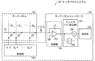
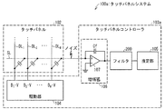
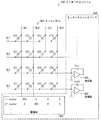
図13は、従来のタッチパネルシステム900の構成を示す模式図である。また、図14は、タッチパネルシステム900の駆動方法を説明するための図である。タッチパネルシステム900は、タッチパネル902とタッチパネルコントローラ903とを備える。タッチパネル902は、ドライブラインDL1〜DL4と、センスラインSL1〜SL4と、ドライブラインDL1〜DL4とセンスラインSL1〜SL4とが交差する位置に配置された静電容量C11〜C44とを有している。また、タッチパネルコントローラ903は、駆動部904及び増幅器908を有している。
FIG. 13 is a schematic diagram showing a configuration of a conventional touch panel system 900. FIG. 14 is a diagram for explaining a driving method of the touch panel system 900. The touch panel system 900 includes a touch panel 902 and a
以下に、タッチパネルシステム900においては、どのような方法によって静電容量値を測定値(検出値)に変換しているのか説明する。 The following describes how the touch panel system 900 converts the capacitance value into a measurement value (detection value) by using a method.
駆動部904は、図14の式3に示される、4行4列の符号系列に基づいて、ドライブラインDL1〜DL4を駆動する。符号系列の要素が「1」であれば、駆動部904は電源電圧VDDを印加し、要素が「0」であれば、ゼロボルトを印加する。
The
タッチパネルシステム900は、センスラインSL1〜SL4のそれぞれに対応するように配置された、4個の増幅器908を有している。4個の増幅器908は、駆動部904により駆動されたセンスラインSL1〜SL4に沿った、静電容量の線形和Y1〜Y4を受け取って増幅する。
The touch panel system 900 includes four
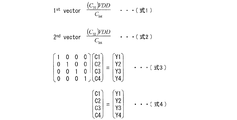
具体的には、例えば、上記4行×4列の符号系列による4回の駆動のうちの最初の駆動では、駆動部904はドライブラインDL1に電源電圧VDDを印加し、残りのドライブラインDL2〜DL4にゼロボルトを印加する。すると、例えばセンスラインSL3からは、図14の式1で示される静電容量C31に対応する出力が測定値Y1として増幅器908に供給される。
Specifically, for example, in the first drive among the four times of the 4 rows × 4 columns code sequence, the
そして、2回目の駆動では、ドライブラインDL2に電源電圧VDDを印加し、残りのドライブラインDL1、DL3、DL4にゼロボルトを印加する。すると、センスラインSL3からは、図14の式2で示される静電容量C32に対応する出力が測定値Y2として増幅器908に供給される。
In the second drive, the power supply voltage VDD is applied to the drive line DL2, and zero volts is applied to the remaining drive lines DL1, DL3, and DL4. Then, an output corresponding to the capacitance C32 represented by the
同様に、3回目の駆動では、ドライブラインDL3に電源電圧VDDを印加し、残りのドライブラインにゼロボルトを印加する。その後、4回目の駆動では、ドライブラインDL4に電源電圧VDDを印加し、残りのドライブラインにゼロボルトを印加する。3回目の駆動、4回目の駆動によって、それぞれ、静電容量C3、C4に対応する測定値Y3、Y4が得られる。 Similarly, in the third drive, the power supply voltage VDD is applied to the drive line DL3, and zero volts is applied to the remaining drive lines. Thereafter, in the fourth drive, the power supply voltage VDD is applied to the drive line DL4, and zero volts is applied to the remaining drive lines. The measurement values Y3 and Y4 corresponding to the capacitances C3 and C4 are obtained by the third driving and the fourth driving, respectively.
以上によって、図14の式3及び式4に示すように、測定値Y1、Y2、Y3、Y4が、それぞれ、静電容量値C1、C2、C3、C4と関連付けられる。
As described above, the measured values Y1, Y2, Y3, and Y4 are associated with the capacitance values C1, C2, C3, and C4 as shown in
前述のように、タッチパネル900では、静電容量値から測定値(検出値)を得ることができる。 As described above, the touch panel 900 can obtain a measured value (detected value) from the capacitance value.
しかしながら、タッチパネルシステム900では、1回の測定で1本のドライブラインと交差する容量データしか取得できず、ノイズ成分が小さくならず、静電容量の容量変化を正しく検出することが困難であるという問題がある。 However, the touch panel system 900 can acquire only capacitance data intersecting with one drive line in one measurement, the noise component is not reduced, and it is difficult to correctly detect the capacitance change of the capacitance. There's a problem.
すなわち、従来のタッチパネルシステム900は、ノイズの影響を受けやすい、言い換えればノイズ耐性が低い、という問題がある。 That is, the conventional touch panel system 900 has a problem that it is easily affected by noise, in other words, has low noise resistance.
本発明は、上記の問題点に鑑みてなされたものであり、その目的は、ノイズ耐性の高い線形系係数推定方法及びそれを用いた集積回路、タッチパネルシステム、及び電子機器を提供することにある。 The present invention has been made in view of the above problems, and an object thereof is to provide a linear system coefficient estimation method having high noise resistance, an integrated circuit using the same, a touch panel system, and an electronic apparatus. .
本発明に係る静電容量値推定方法は、タッチパネルのセンスラインとM本(Mは複数)のドライブラインとの交点に存在するM個の静電容量をN個(Nは複数)のM次元ベクトルに基づいて並列に駆動する駆動部と、前記静電容量の電荷に基づくN個の線形和信号を受け取る線形和信号取得部と、前記N個の線形和信号のノイズを除去するノイズ除去部と、前記N個の線形和信号に基づく信号と前記N個のM次元ベクトルとの内積演算により前記M個の静電容量値を推定する推定部とを有する集積回路を備えたタッチパネルシステムにおいて、前記M個の静電容量値を推定する静電容量値推定方法であって、前記ノイズ除去部が、前記線形和信号取得部により得られた前記N個の線形和信号に重畳したノイズを、前記線形和信号をフィルタリングすることによって除去するノイズ除去工程と、前記推定部が、前記ノイズ除去工程によりノイズを除去された前記N個の線形和信号に基づく信号と、前記N個のM次元ベクトルとの内積演算により前記M個の静電容量値を推定する推定工程とを包含することを特徴としている。 The capacitance value estimation method according to the present invention is based on M (N is a plurality) M dimensions of M capacitances existing at the intersections of a touch line sense line and M (M is a plurality) drive lines. A drive unit that drives in parallel based on a vector, a linear sum signal acquisition unit that receives N linear sum signals based on the charges of the capacitance, and a noise removal unit that removes noise from the N linear sum signals And a touch panel system including an integrated circuit having an estimation unit that estimates the M capacitance values by an inner product operation of a signal based on the N linear sum signals and the N M-dimensional vectors, a capacitance value estimation method for estimating the M capacitance value, the noise removal unit, superimposed on the linear sum signal before Symbol N linear sum signal obtained by the acquisition unit noise Filter the linear sum signal A noise removal step of removing by grayed, the estimation unit, and a signal based on the N linear sum signal removed of noise by said noise removing step, the inner product operation of the N M-dimensional vector An estimation step of estimating the M capacitance values.
上記特徴によれば、対象係数のN個の線形和信号に重畳したノイズを、前記線形和信号をフィルタリングすることによって除去し、前記ノイズを除去されたN個の線形和信号に基づく信号と、前記N個のM次元ベクトルとの内積演算により前記M個の対象係数の値を推定する。 According to the above feature, noise superimposed on the N linear sum signals of the target coefficient is removed by filtering the linear sum signal, and the signal based on the N linear sum signals from which the noise has been removed; The values of the M target coefficients are estimated by an inner product operation with the N M-dimensional vectors.
そのため、M個の対象係数の値は、線形和信号のフィルタリングによってノイズが除去された上で推定される。従って、推定されるM個の対象係数の値は、ノイズによって影響を受けない。すなわち、本発明に係る線形系係数推定方法は、ノイズ耐性が高い線形系係数推定方法である。 Therefore, the values of M target coefficients are estimated after noise is removed by filtering of the linear sum signal. Accordingly, the estimated values of the M target coefficients are not affected by noise. That is, the linear system coefficient estimation method according to the present invention is a linear system coefficient estimation method with high noise tolerance.
本発明に係る静電容量値推定方法では、前記ノイズ除去部は、遅延部と減算部とを備えた離散時間フィルタを含んでおり、前記ノイズ除去工程において、(i)前記遅延部は、前記線形和信号取得部からの前記線形和信号を遅延させて出力し、(ii)前記減算部は、前記線形和信号取得部からの前記線形和信号から、前記遅延部から出力される線形和信号を減算することが好ましい。 In the electrostatic capacitance value estimation method according to the present invention, the noise removing unit includes a discrete-time filter and a subtraction unit and a delay unit, Oite the noise removing step, (i) the delay unit The linear sum signal from the linear sum signal acquisition unit is delayed and output, and (ii) the subtraction unit is output from the delay unit from the linear sum signal from the linear sum signal acquisition unit It is preferable to subtract the sum signal .
上記構成によれば、ノイズ除去工程において使用されるフィルタは離散時間フィルタである。 According to the said structure, the filter used in a noise removal process is a discrete time filter.
そのため、1つまたは複数の遅延素子と加算器を主たる構成部材として、フィルタリングに使用されるフィルタを容易に構成することができる。 Therefore, a filter used for filtering can be easily configured with one or more delay elements and an adder as main components.
本発明に係る静電容量値推定方法では、前記遅延部は、前記線形和信号取得部より得られた前記線形和信号を、所定のクロック数分遅延させる構成であり、前記駆動部は、符号長NのM系列に基づくN個の符号系列から、上記遅延部により遅延された所定のクロック数に対応する符号系列が含まれないようにK個の符号系列(K<N)を選択して、前記N個のM次元ベクトルを構成することが好ましい。 In the capacitance value estimation method according to the present invention, the delay unit is configured to delay the linear sum signal obtained from the linear sum signal acquisition unit by a predetermined number of clocks. K code sequences (K <N) are selected from N code sequences based on a long N M sequence so that a code sequence corresponding to a predetermined number of clocks delayed by the delay unit is not included. Preferably, the N M-dimensional vectors are configured.
ハードウェア化の容易なM系列を使用してN個のM次元ベクトルを構成すると、該N個のM次元ベクトルに含まれる、あるM次元ベクトルD1を遅延クロック分遅延させたベクトルD2もまた上記N個のM次元ベクトルに含まれる。上記D1、D2が共に含まれている線形和信号から計算による対象係数の推定を行うとき、D1とD2間の前述の関係によって、上記計算が煩雑になることがある。 When N M-dimensional vectors are configured using an M-sequence that is easily implemented in hardware, a vector D2 obtained by delaying a certain M-dimensional vector D1 by a delay clock is also included in the N M-dimensional vectors. It is included in N M-dimensional vectors. When the target coefficient is estimated by calculation from the linear sum signal including both D1 and D2, the calculation may be complicated due to the above-described relationship between D1 and D2.
しかしながら、上記構成によれば、符号長NのM系列に基づくN個の符号系列から選択され構成されたK個のM次元ベクトルには、ある符号系列に対して遅延クロック分遅延させた符号系列が含まれない。 However, according to the above configuration, a code sequence obtained by delaying a certain code sequence by a delay clock is included in K M-dimensional vectors selected from N code sequences based on an M sequence having a code length of N. Is not included.
そのため、対象係数の推定のための上記計算が煩雑にならない。 Therefore, the calculation for estimating the target coefficient is not complicated.
本発明に係る静電容量値推定方法では、前記ノイズ除去部は、遅延素子と係数計算部と可変ゲイン部と減算部とを備えた適応フィルタを含んでおり、前記ノイズ除去工程において、(i)前記遅延素子は、前記線形和信号取得部から得られた前記線形和信号を遅延させた出力信号を出力し、(ii)前記係数計算部は、前記線形和信号取得部により得られた前記N個の線形和信号と前記遅延素子からの前記出力信号との相関を計算し、(iii)前記可変ゲイン部は、前記係数計算部による前記相関の計算結果に応じて、前記遅延素子からの前記出力信号に対してゲインを与え、(iv)前記減算部は、前記線形和信号取得部からの前記線形和信号から、前記可変ゲイン部によりゲインを与えられた前記出力信号を減算することが好ましい。 The capacitance value estimation method according to the present invention, the noise removing unit includes an adaptive filter that includes a subtraction unit and the delay elements and the coefficient calculation unit and the variable gain section, Oite the noise removing step, (i) The delay element outputs an output signal obtained by delaying the linear sum signal obtained from the linear sum signal acquisition unit, and (ii) the coefficient calculation unit is obtained by the linear sum signal acquisition unit. A correlation between the N linear sum signals and the output signal from the delay element; and (iii) the variable gain unit is configured to output the delay element according to the correlation calculation result by the coefficient calculation unit. (Iv) The subtraction unit subtracts the output signal given gain by the variable gain unit from the linear sum signal from the linear sum signal acquisition unit. It is preferable.
上記構成によれば、適応フィルタが、入力された線形和信号に対して伝達関数を自己適応させる。 According to the above configuration, the adaptive filter self-adapts the transfer function to the input linear sum signal.
そのため、入力された線形和信号に重畳したノイズが変化しても、当該変化したノイズに最適なフィルタによってフィルタリングされる。従って、ノイズを最適に除去することができる。 For this reason, even if the noise superimposed on the input linear sum signal changes, it is filtered by the optimum filter for the changed noise. Therefore, noise can be removed optimally.
あるいは、上記構成によれば、ノイズの特性が変化した場合であってもノイズを最も効果的に減衰できる伝達関数を選択することができるので、ノイズ耐性の高い線形系係数推定方法を提供することができる。 Alternatively, according to the above configuration, it is possible to select a transfer function that can attenuate the noise most effectively even when the characteristics of the noise change, and thus provide a linear system coefficient estimation method with high noise resistance. Can do.
本発明に係る集積回路は、タッチパネルのセンスラインとM本(Mは複数)のドライブラインとの交点に存在するM個の静電容量をN個(Nは複数)のM次元ベクトルに基づいて並列に駆動する駆動部と、前記静電容量の電荷に基づくN個の線形和信号を受け取る線形和信号取得部とを備えた集積回路であって、前記線形和信号取得部により得られた前記N個の線形和信号に重畳したノイズを、前記線形和信号をフィルタリングすることによって除去するノイズ除去部と、前記ノイズ除去部によりノイズを除去されたN個の線形和信号に基づく信号と、前記N個のM次元ベクトルとの内積演算により前記M個の静電容量値を推定する推定部とをさらに備えたことを特徴とする。 The integrated circuit according to the present invention is based on N (N is a plurality) M-dimensional vectors of M capacitances existing at the intersections of the touch line sense lines and M (M is a plurality) drive lines. a driving unit for driving in parallel, the an integrated circuit that includes a linear sum signal acquisition unit for receiving the N linear sum signal based on the electric charge of the capacitance, before obtained by the linear sum signal acquisition unit the noise superimposed on the serial N linear sum signal, and a noise removing unit for removing by filtering the linear sum signal, a signal based on the N linear sum signal removed of noise by the pre-Symbol noise removing unit And an estimation unit for estimating the M electrostatic capacitance values by an inner product operation with the N M-dimensional vectors.
上記特徴によれば、ノイズ除去部が、対象係数のN個の線形和信号に重畳したノイズを、前記線形和信号をフィルタリングすることによって除去し、推定部が、ノイズを除去されたN個の線形和信号に基づく信号と、前記N個のM次元ベクトルとの内積演算により前記M個の対象係数の値を推定する。 According to the above feature, the noise removing unit removes the noise superimposed on the N linear sum signals of the target coefficient by filtering the linear sum signal, and the estimating unit removes the N pieces of noise from which the noise has been removed. The values of the M target coefficients are estimated by an inner product operation of a signal based on a linear sum signal and the N M-dimensional vectors.
そのため、M個の対象係数の値は、線形和信号のノイズが除去された上で推定される。従って、推定されるM個の対象係数の値は、ノイズによって影響を受けない。すなわち、本発明に係る集積回路は、ノイズ耐性が高い集積回路である。 Therefore, the values of the M target coefficients are estimated after removing the noise of the linear sum signal. Accordingly, the estimated values of the M target coefficients are not affected by noise. That is, the integrated circuit according to the present invention is an integrated circuit having high noise resistance.
本発明に係る集積回路では、前記ノイズ除去部は、(i)前記線形和信号取得部からの前記線形和信号を遅延させて出力する遅延部と、(ii)前記線形和信号取得部からの前記線形和信号から、前記遅延部から出力される線形和信号を減算する減算部と、を備えた離散時間フィルタを含むことが好ましい。 In the integrated circuit according to the present invention, the noise removing unit includes: (i) a delay unit that delays and outputs the linear sum signal from the linear sum signal acquisition unit; and (ii) an output from the linear sum signal acquisition unit. It is preferable to include a discrete time filter including a subtracting unit that subtracts the linear sum signal output from the delay unit from the linear sum signal .
上記構成によれば、1つまたは複数の遅延素子と加算器とを主として、ノイズ除去部を容易に構成することができる。 According to the above configuration, the noise removing unit can be easily configured mainly using one or a plurality of delay elements and an adder.
本発明に係る集積回路において、前記遅延部は、前記線形和信号取得部より得られた前記線形和信号を、所定のクロック数分遅延させ、前記駆動部は、符号長NのM系列に基づくN個の符号系列から、上記遅延部により遅延された所定の遅延クロック数に対応する符号系列が含まれないようにK個の符号系列(K<N)を選択して、前記N個のM次元ベクトルを構成することが好ましい。 An integrated circuit according to the present invention, the delay unit, the linear sum signal the linear sum signal obtained from the obtaining unit, delays a predetermined number of clock, the drive unit is based on the M sequence code length N K code sequences (K <N) are selected from the N code sequences so as not to include a code sequence corresponding to a predetermined number of delay clocks delayed by the delay unit , and the N M sequences are selected. It is preferable to construct a dimension vector .
上記構成によれば、M次元ベクトル構成部によって符号長NのM系列に基づくN個の符号系列から選択され構成されたK個のM次元ベクトルには、ある符号系列に対して遅延クロック分遅延させた符号系列が含まれない。 According to the above configuration, the K M-dimensional vectors selected from the N code sequences based on the M sequences of the code length N by the M-dimensional vector configuration unit are delayed by a delay clock with respect to a certain code sequence. Does not include the coded code sequence.
そのため、対象係数の推定のための上記計算が煩雑にならない。 Therefore, the calculation for estimating the target coefficient is not complicated.
本発明に係る集積回路では、前記ノイズ除去部は、(i)前記線形和信号取得部から得られた前記線形和信号を遅延させた出力信号を出力する遅延素子と、(ii)前記線形和信号取得部により得られた前記N個の線形和信号と前記遅延素子からの前記出力信号との相関を計算する係数計算部と、(iii)前記係数計算部による前記相関の計算結果に応じて、前記遅延素子からの前記出力信号に対してゲインを与える可変ゲイン部と、(iv)前記線形和信号取得部からの前記線形和信号から、前記可変ゲイン部によりゲインを与えられた前記出力信号を減算する減算部と、を備えた適応フィルタを含むことが好ましい。 In the integrated circuit according to the present invention, the noise removal unit includes: (i) a delay element that outputs an output signal obtained by delaying the linear sum signal obtained from the linear sum signal acquisition unit; and (ii) the linear sum. A coefficient calculation unit for calculating a correlation between the N linear sum signals obtained by the signal acquisition unit and the output signal from the delay element; and (iii) according to the calculation result of the correlation by the coefficient calculation unit. A variable gain unit that gives a gain to the output signal from the delay element; and (iv) the output signal that is gained by the variable gain unit from the linear sum signal from the linear sum signal acquisition unit. It is preferable to include an adaptive filter including a subtracting unit that subtracts .
上記構成によれば、ノイズ除去部に含まれる適応フィルタが、入力された線形和信号に対して伝達関数を自己適応させる。 According to the above configuration, the adaptive filter included in the noise removal unit self-adapts the transfer function to the input linear sum signal.
そのため、ノイズ除去部は、入力された線形和信号に重畳したノイズが変化しても、当該変化したノイズに最適なフィルタによってフィルタリングを行う。従って、ノイズを最適に除去することができる。 Therefore, even if the noise superimposed on the input linear sum signal changes, the noise removing unit performs filtering using a filter that is optimal for the changed noise. Therefore, noise can be removed optimally.
本発明に係るタッチパネルシステムは、本発明に係る集積回路と、前記センスラインと前記M本のドライブラインとを有する前記タッチパネルとを備え、前記集積回路は、前記M本のドライブラインと前記センスラインとの交点の前記静電容量が有するM個の静電容量値を推定することを特徴とする。 A touch panel system according to the present invention includes the integrated circuit according to the present invention, and the touch panel having the sense lines and the M drive lines, and the integrated circuit includes the M drive lines and the sense lines. The M capacitance values of the capacitance at the intersection with are estimated .
上記特徴によれば、本発明のタッチパネルシステムに備えられた集積回路に設けられたノイズ除去部が、対象係数のN個の線形和信号に重畳したノイズを、前記線形和信号をフィルタリングすることによって除去し、推定部が、ノイズを除去されたN個の線形和信号に基づく信号と、前記N個のM次元ベクトルとの内積演算により前記M個の対象係数の値を推定する。 According to the above feature, the noise removing unit provided in the integrated circuit included in the touch panel system of the present invention filters the noise that is superimposed on the N linear sum signals of the target coefficient, by filtering the linear sum signal. The estimation unit estimates the value of the M target coefficients by an inner product operation of the signal based on the N linear sum signals from which noise is removed and the N M-dimensional vectors.
そのため、M個の対象係数の値は、線形和信号のノイズが除去された上で推定される。従って、推定されるM個の対象係数の値は、ノイズによって影響を受けない。すなわち、本発明に係るタッチパネルシステムは、ノイズ耐性が高いタッチパネルシステムである。 Therefore, the values of the M target coefficients are estimated after removing the noise of the linear sum signal. Accordingly, the estimated values of the M target coefficients are not affected by noise. That is, the touch panel system according to the present invention is a touch panel system with high noise resistance.
本発明に係る電子機器は、本発明に係る集積回路と、前記センスラインと前記M本のドライブラインとを有する前記タッチパネルと、前記タッチパネルに重ねられているか、前記タッチパネルを内蔵した表示パネルとを備え、前記集積回路は、前記M本のドライブラインと前記センスラインとの交点の前記静電容量が有するM個の静電容量値を推定することを特徴とする。 An electronic apparatus according to the present invention includes an integrated circuit according to the present invention, the touch panel having the sense line and the M drive lines, and a display panel that is superimposed on the touch panel or has the touch panel built therein. And the integrated circuit estimates M capacitance values of the capacitance at the intersection of the M drive lines and the sense lines .
上記特徴によれば、本発明の電子機器に備えられた集積回路に設けられたノイズ除去部が、対象係数のN個の線形和信号に重畳したノイズを、前記線形和信号をフィルタリングすることによって除去し、推定部が、ノイズを除去されたN個の線形和信号に基づく信号と、前記N個のM次元ベクトルとの内積演算により前記M個の対象係数の値を推定する。 According to the above feature, the noise removal unit provided in the integrated circuit provided in the electronic apparatus of the present invention filters the linear sum signal for noise superimposed on the N linear sum signals of the target coefficient. The estimation unit estimates the value of the M target coefficients by an inner product operation of the signal based on the N linear sum signals from which noise is removed and the N M-dimensional vectors.
そのため、M個の対象係数の値は、線形和信号のノイズが除去された上で推定される。従って、推定されるM個の対象係数の値は、ノイズによって影響を受けない。すなわち、本発明に係る電子機器は、ノイズ耐性が高い電子機器である。 Therefore, the values of the M target coefficients are estimated after removing the noise of the linear sum signal. Accordingly, the estimated values of the M target coefficients are not affected by noise. That is, the electronic device according to the present invention is an electronic device with high noise resistance.
以上のように、本発明に係る静電容量値推定方法は、タッチパネルのセンスラインとM本(Mは複数)のドライブラインとの交点に存在するM個の静電容量をN個(Nは複数)のM次元ベクトルに基づいて並列に駆動する駆動部と、前記静電容量の電荷に基づくN個の線形和信号を受け取る線形和信号取得部と、前記N個の線形和信号のノイズを除去するノイズ除去部と、前記N個の線形和信号に基づく信号と前記N個のM次元ベクトルとの内積演算により前記M個の静電容量値を推定する推定部とを有する集積回路を備えたタッチパネルシステムにおいて、前記M個の静電容量値を推定する静電容量値推定方法であって、前記ノイズ除去部が、前記線形和信号取得部により得られた前記N個の線形和信号に重畳したノイズを、前記線形和信号をフィルタリングすることによって除去するノイズ除去工程と、前記推定部が、前記ノイズ除去工程によりノイズを除去された前記N個の線形和信号に基づく信号と、前記N個のM次元ベクトルとの内積演算により前記M個の静電容量値を推定する推定工程とを包含する構成である。 As described above, the capacitance value estimation method according to the present invention uses N (N is N) capacitances existing at the intersections of the touch line sense lines and M drive lines (M is a plurality). A plurality of drive units that are driven in parallel based on M-dimensional vectors, a linear sum signal acquisition unit that receives N linear sum signals based on charges of the capacitance, and noise of the N linear sum signals. An integrated circuit having a noise removing unit for removing, and an estimating unit for estimating the M capacitance values by an inner product operation of a signal based on the N linear sum signals and the N M-dimensional vectors. in a touch panel system, said a capacitance value estimation method for estimating the M capacitance value, the noise removal unit, the linear sum signal acquisition SL before obtained by the unit N linear sum signal The noise superimposed on A noise removal step of removing by filtering, the estimation unit comprises a signal based on the N linear sum signal noise has been removed by said noise removing step, the inner product operation between the N M-dimensional vector And an estimation step of estimating the M capacitance values.
これにより、ノイズ耐性が高い線形系係数推定方法を提供することができるという効果を奏する。 Thereby, there is an effect that it is possible to provide a linear system coefficient estimation method having high noise tolerance.
以下、本発明の実施例について、図1〜12を参照しながら詳細に説明する。なお、各実施形態に記載されている構成部品の寸法、材質、形状、相対配置などは、特に特定的な記載がない限り、この発明の範囲をそれのみに限定する趣旨ではなく、単なる説明に過ぎない。
(実施の形態の前提となる構成)
(線形系係数推定方法の例;タッチパネルシステム800)
図12は、本発明の参考例に係るタッチパネルシステム800の構成を示す模式図である。
Hereinafter, embodiments of the present invention will be described in detail with reference to FIGS. It should be noted that the dimensions, materials, shapes, relative arrangements, etc. of the components described in each embodiment are not intended to limit the scope of the present invention only, unless otherwise specified, but only for explanation. Not too much.
(Configuration that is the premise of the embodiment)
(Example of linear system coefficient estimation method; touch panel system 800)
FIG. 12 is a schematic diagram showing a configuration of a touch panel system 800 according to a reference example of the present invention.
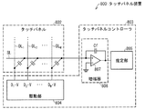
タッチパネルシステム800は、タッチパネル802とタッチパネルコントローラ803とを備えている。タッチパネル802は、M本のドライブラインDL1〜DLMと、複数のセンスラインとを有している。但し、説明の簡潔化のために、センスラインは1本のセンスラインSLのみが設けられているものとして説明する。ドライブラインDL1〜DLMとセンスラインSLとが交差する位置には、静電容量値がそれぞれC1〜CMである静電容量C1〜CMが配置されている。
The touch panel system 800 includes a
タッチパネルコントローラ803には、駆動部804が設けられている。駆動部804は、ドライブラインDL1〜DLMを並列に駆動する。符号系列Hの要素が「1」であれば、駆動部804は電圧Vを印加し、要素が「−1」であれば、電圧−Vを印加する。
The
タッチパネルコントローラ803は、センスラインSLに対応する位置に配置された増幅器806を有している。増幅器806は、駆動部804により駆動された静電容量のセンスラインSLに沿った下記の(式5)により示される線形和信号Sjを受け取って増幅する。
The

ここで、N個のM次元ベクトルをDi,jとおいた。また、推定されるべき対象係数Akは、内積計算によって、 Here, N M-dimensional vectors are denoted as Di, j . The target coefficient A k to be estimated is calculated by the inner product calculation.
と表される。式6に前述のSjを代入すると、
It is expressed. Substituting the aforementioned S j into
で与えられる。ここで、ベクトルDi,j(i=1、・・、M;j=1、・・N)がそれぞれ互いに直交であるとすれば、同一ベクトル同士の内積は1、異なるベクトル同士の内積は0になるので、 Given in. If the vectors D i, j (i = 1,..., M; j = 1,... N) are orthogonal to each other, the inner product of the same vectors is 1, and the inner product of different vectors is Because it becomes 0
![]()
![]()
となる。ただし、k=1、・・・、M。 It becomes. However, k = 1,..., M.
さて、センスラインにノイズNojが重畳される場合には、線形和Sjは、 Now, when noise No j is superimposed on the sense line, the linear sum S j is
となる。また、内積演算によって推定される対象係数Akは、 It becomes. The target coefficient A k estimated by the inner product calculation is
あるいは、前述のベクトルDi,jの直交条件により、 Alternatively, depending on the orthogonal condition of the vector D i, j described above,
となる。 It becomes.
このように、線形計算によって対象係数を推定して決定する方法を、線形系係数推定方法と呼ぶ。 A method of estimating and determining the target coefficient by linear calculation in this way is called a linear system coefficient estimation method.
タッチパネルシステム800の線形系係数推定方法では、上式のように、ノイズNojとベクトルDi,jの内積に応じた誤りが対象係数Akの推定値((式11)の右辺第2項)に生じるため、対象係数Akはノイズの影響を受けやすい、言い換えれば上記線形系係数推定方法によって決定される対象係数Akはノイズ耐性が低い。従って、タッチパネルシステム800は、ノイズ耐性が低い。
(実施の形態1)
(タッチパネルシステム100の構成)
本発明に係るタッチパネルシステム100を図1に示す。
In the linear system coefficient estimation method of the touch panel system 800, an error corresponding to the inner product of the noise No j and the vector D i, j is an estimated value of the target coefficient Ak (the second term on the right side of (Expression 11)), as in the above expression. ), The target coefficient A k is easily affected by noise. In other words, the target coefficient A k determined by the linear system coefficient estimation method has low noise resistance. Therefore, the touch panel system 800 has low noise resistance.
(Embodiment 1)
(Configuration of touch panel system 100)
A
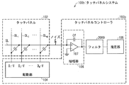
タッチパネルシステム100は、タッチパネル102とタッチパネルコントローラ103とを備えている。タッチパネル102は、M本のドライブラインDL1〜DLMと、1本のセンスラインSLとを有している。ドライブラインDL1〜DLMとセンスラインSLとが交差する位置には、静電容量値がそれぞれC1〜CMである静電容量C1〜CMが配置されている。
The
タッチパネルコントローラ103には、駆動部104が設けられている。駆動部104は、ドライブラインDL1〜DLMを並列に駆動する。符号系列Hの要素が「1」であれば、駆動部104は電圧Vを印加し、要素が「−1」であれば、電圧−Vを印加する。
The
タッチパネルコントローラ103は、センスラインSLに対応する位置に配置された増幅器106を有している。増幅器106は、オペアンプ107と、一端がオペアンプ107の非反転入力端子に接続され、他端がオペアンプ107の出力に接続された積分容量Cfとを有している。増幅器106は、駆動部104により駆動された静電容量のセンスラインSLに沿った線形和信号を受け取って増幅する。
The
タッチパネルシステム100は、図12に示した参考に係るタッチパネルシステム800と、一部を除いて同様の構成である。タッチパネルシステム100とタッチパネルシステム800との相違点は、タッチパネルシステム100では、増幅器106と推定部105との間にフィルタ101(ノイズ除去部、離散時間フィルタ)を含んでいるが、タッチパネルシステム800はフィルタ101を含んでいないことである。なお、本実施例では、センスラインSL数を1(SL)とし、ドライブラインDL数を7(DL1〜DL7)とする。
The
フィルタ101は、増幅器106からの線形和信号を遅延させて供給する遅延器108と、増幅器106からの線形和信号から、遅延器108から出力される線形和信号を減算して推定部105に供給する減算器109とを有している。
The
推定部105は、フィルタ101によりノイズを除去された線形和信号に基づく信号と、N個のM次元ベクトルとの内積演算によりM個の静電容量の値を推定する。
(タッチパネルシステム100の動作例)
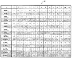
本実施例では、符号長が15のM系列を用いて、センスラインの容量を駆動する。図2に、符号長が15のM系列の符号系列MCの例を示す。本実施例では、ドライブライン数を7としているので、図2に示す15個の系列E1,j〜E15,jのうち7つを使用する。本実施例のフィルタ101は、信号を1クロック遅らせるブロック(遅延器108)を含む。そのため、たとえば図2の系列E1,jを使用する場合、系列E2,jを1クロック遅らせた信号が、系列E1,jとなるが、これらの系列を同時に使用することは避けるべきである。そこで、本実施例では、Di,j=E2i−1,j(i=1、・・、7)となる系列Di,jを使用する。
The
(Operation example of touch panel system 100)
In the present embodiment, the sense line capacitance is driven using an M-sequence having a code length of 15. FIG. 2 shows an example of an M-sequence code sequence MC having a code length of 15. In this embodiment, since the number of drive lines is 7, seven of the 15 sequences E1, j to E15, j shown in FIG. 2 are used. The
このように、実施の形態1に係る15個の7次元ベクトルは、符号長15のM系列の符号系列MCに基づく15個の符号系列から、遅延クロック分遅延させた符号系列が含まれないように7個の符号系列(K<N)を選択して構成する。
Thus, the 15 7-dimensional vectors according to
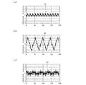
図3(a)にノイズが重畳される前の線形和信号S1、図3(b)にノイズが重畳された後の信号S2、図3(c)にフィルタ101の出力信号S3を示す。縦軸は正規化された信号振幅を表し、横軸は時間を表す。出力信号S3は、ノイズ重畳後の信号S2と比較して、ノイズの振幅が低くなっていることが分かる。
FIG. 3A shows the linear sum signal S1 before the noise is superimposed, FIG. 3B shows the signal S2 after the noise is superimposed, and FIG. 3C shows the output signal S3 of the
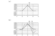
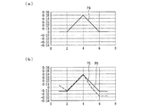
つづいて、図4(a)にタッチパネル102に形成された容量パターンP1を示し、推定部105で推定された容量パターンP2を図4(b)に示す。破線が本発明のフィルタ101を使用しない場合における容量パターンP3、実線が本発明のフィルタ101を使用した場合における推定された容量パターンP2である。縦軸は、正規化された容量値を示し、横軸は容量が設置されたドライブラインの番号を示す。フィルタ101を使用した容量パターンP2は、フィルタ101を使用しない容量パターンP3よりも、入力容量パターンP1により近い推定パターンとなっている。
Next, FIG. 4A shows the capacitance pattern P1 formed on the
なお、タッチパネルシステム100では、フィルタ101の代わりに、線形和信号に対して伝達関数を変更可能なフィルタを用いてもよい。そうすれば、ノイズを最も効果的に減衰できる伝達関数を選択することによって、ノイズ耐性の高いタッチパネルシステム100を提供することができる。
(本発明の線形系係数推定方法)
タッチパネルシステム100において使用される、本発明に係る線形系係数推定方法の一例を説明する。
In the
(Linear system coefficient estimation method of the present invention)
An example of the linear system coefficient estimation method according to the present invention used in the
タッチパネルシステム100では、N個のM次元ベクトルにより、複数の対象係数を並列駆動して得た前記対象係数のN個の線形和信号に対して、フィルタリングを行うことでノイズを減衰させる。上記フィルタリングに使用されるフィルタ101の伝達関数をHn=1−z−1とする。
In the
静電容量値をCi(i=1、・・・、M)とする線形和信号 Linear sum signal with capacitance value C i (i = 1,..., M)
に対して、フィルタ101を適用すると、
On the other hand, when the
となる。(式13)において、ノイズ信号の周波数が小さい場合は、Noj−Noj−1≒0となり、ノイズを軽減することができることがわかる。 It becomes. In (Equation 13), when the frequency of the noise signal is small, No j −No j−1 ≈0, which indicates that the noise can be reduced.
しかしながら、上式の右辺第二項はDi,j−1を含んでいる。M次元ベクトルDi,jとして、ハードウェア化の容易なM系列を使用する場合、あるベクトルを1クロック分遅延させたベクトルは、別のベクトルになる。ここで、Di,j−1=Di+1,jと表せる。これを(式13)の右辺第二項に代入すると、Sojは、 However, the second term on the right side of the above equation includes Di , j-1 . When an M sequence that is easily implemented in hardware is used as the M-dimensional vector D i, j , a vector obtained by delaying a certain vector by one clock becomes another vector. Here, D i, j−1 = D i + 1, j can be expressed. By substituting this into the second term on the right side of (Equation 13), So j becomes
となる。このとき、ノイズがほぼゼロになったとすると、内積演算によって推定される対象係数Akは、(式6)および(式14)から、 It becomes. At this time, if the noise is almost zero, the target coefficient A k estimated by the inner product calculation is expressed by (Expression 6) and (Expression 14):
と表せる。ここで、異なるベクトルの内積は無視できるほど小さいとすると、 It can be expressed. Here, if the inner product of different vectors is negligibly small,
となる。この場合、対象係数Akは隣り合う係数Ck、Ck−1の差分となる。そこで、 It becomes. In this case, the target coefficient A k is a difference between adjacent coefficients C k and C k−1 . there,
![]()
![]()
なる係数Bkを計算することにより、Ckを推定することができる。 C k can be estimated by calculating the coefficient B k .
また、あるベクトルを1クロック遅延させたベクトルの使用を避けながら、Ckの推定をすることが可能である。たとえば、2N個のM次元ベクトルであるM系列Ei,jを用意し、E2i,j=Di,jで定義すれば、 In addition, it is possible to estimate C k while avoiding the use of a vector obtained by delaying a certain vector by one clock. For example, if an M sequence E i, j that is 2N M-dimensional vectors is prepared and defined by E 2i, j = D i, j ,
は、 Is
となる。 It becomes.
ゆえに、内積演算によって推定される対象係数Akは、ノイズがほぼゼロになったとした場合、(式2)および(式19)から、 Therefore, the target coefficient A k estimated by the inner product operation is calculated from (Equation 2) and (Equation 19) when the noise is almost zero.
となる。Di,j=E2i,jの定義より、Di,jはE2i+1を含まない(異なる)から、異なるベクトルの内積は無視できるほど小さいとすれば、 It becomes. From the definition of D i, j = E 2i, j , D i, j does not include (different) E 2i + 1 , so if the inner product of different vectors is negligibly small,
となる。 It becomes.
このように、本実施の形態の線形系係数推定方法によれば、推定される対象係数Akを表す式がノイズNojを含まない。従って、対象係数AkはノイズNojの影響を受けない。 Thus, according to the linear system coefficient estimating method of this embodiment, the formula representing the target coefficients A k to be estimated does not include the noise No j. Therefore, the target coefficient A k is not affected by the noise No j .
従って、本実施の形態の線形系係数推定方法によれば、ノイズを軽減でき、ノイズ耐性の高いタッチパネルシステム100を提供することができる。
(実施の形態2)
本発明の集積回路、タッチパネルシステム、及び電子機器に使用するフィルタの別の例として、係数を変更可能なフィルタ200およびフィルタ2000(適応フィルタ)について、図5〜図10に基づいて説明する。
Therefore, according to the linear system coefficient estimation method of the present embodiment, it is possible to provide a
(Embodiment 2)
As another example of the filter used in the integrated circuit, the touch panel system, and the electronic apparatus of the present invention, a
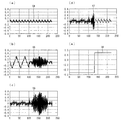
まず、集積回路、タッチパネルシステム、及び電子機器に使用するフィルタを、係数を変更可能としない場合において、ノイズの特性がある特性からそれとは異なる特性に変化したときの信号の例を図7(a)、図7(b)に示す。図7(a)は特性が変化したノイズを印加する前の線形和信号S4、図7(b)は特性が変化したノイズを印加した後の信号S5を示す。また、係数が変更可能でないノイズフィルタを用いて、信号S5を処理した信号S6を図7(c)に示す。同図から分かるように、ノイズの特性が変化した後では、上記ノイズフィルタはノイズを減衰できていない。
(適応フィルタの例1)
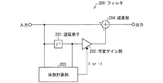
図5に、フィルタ200を備えた本発明のタッチパネルシステム100aの構成の模式図を示す。前述のタッチパネルシステム100との差異は、フィルタ100とは異なるフィルタ200を備えたタッチパネルコントローラ103aである。また、図6に、フィルタ200の構成の模式図を示す。フィルタ200は、遅延素子201、可変ゲイン部202、係数計算部203、および、入力信号から、可変ゲイン部202からの信号を減算する減算部204で構成される。ここで、係数計算部203は、フィルタ200の入力信号と遅延素子201の出力信号との相関を計算し、相関が正であれば1を出力し、負であれば−1を出力する。可変ゲイン部202は、遅延素子201の出力信号に対して係数計算部203の出力信号が1であれば1、−1であれば−1のゲインを持つ。
First, an example of a signal when a filter used in an integrated circuit, a touch panel system, and an electronic device is changed from a characteristic having noise characteristics to a characteristic different from that when the coefficient cannot be changed is shown in FIG. ), As shown in FIG. FIG. 7A shows the linear sum signal S4 before applying noise whose characteristics have changed, and FIG. 7B shows the signal S5 after applying noise whose characteristics have changed. FIG. 7C shows a signal S6 obtained by processing the signal S5 using a noise filter whose coefficients cannot be changed. As can be seen from the figure, after the noise characteristics change, the noise filter cannot attenuate the noise.
(Example 1 of adaptive filter)
In FIG. 5, the schematic diagram of a structure of the touchscreen system 100a of this invention provided with the
フィルタ200を用いて、前述の図7(b)に示した信号S5をフィルタリングした信号S7を図7(d)に示す。また、係数計算部203での出力信号S8を図7(e)に示す。同図によれば、フィルタ200によって、ノイズの特性が変化した後でも、ノイズを減衰できていることがわかる。
A signal S7 obtained by filtering the signal S5 shown in FIG. 7B using the
つづいて、図8(a)に、タッチパネル102に形成された容量パターンP4を示し、図8(b)に、上記容量パターンP4がタッチパネルコントローラ103aに入力されたときの、推定部105により推定された容量パターンP5を示す。図8(b)において、破線は本発明のフィルタを使用しない場合の推定された容量パターンP6、実線がフィルタ200を使用した場合の推定された容量パターンP5である。縦軸は、正規化された容量値を示し、横軸は容量が設置されたドライブラインの番号を示す。フィルタを使用することで、タッチパネル102に形成された容量パターンP4により近い推定の要領パターンP5が得られた。
Next, FIG. 8A shows a capacitance pattern P4 formed on the
このように、係数が変更可能なフィルタ200を用いることで、ノイズの特性が変化した場合でも、ノイズを減衰可能である。
(適応フィルタの例2)
図9に、フィルタ2000を備えたタッチパネルコントローラ103bを含む、本実施の形態のタッチパネルシステム100bの構成を示す模式図を示す。また、図10に、フィルタ200とは別の、係数を変更可能なフィルタ例として、フィルタ2000を示す。前述した構成要素と同一の構成要素には同一の参照符号を付している。従って、これらの構成要素の詳細な説明は繰り返さない。
As described above, by using the
(Example 2 of adaptive filter)
FIG. 9 is a schematic diagram illustrating a configuration of a touch panel system 100b according to the present embodiment including a
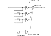
図1、図6では、1クロック分の遅延素子を1つ用いる構成のフィルタの例を示したが、フィルタ2000は、複数個の遅延素子2010を用いた構成である。
Although FIGS. 1 and 6 show an example of a filter having one delay element for one clock, the
フィルタ2000は、N個の遅延素子2010と加算部2040とで構成されるFIR(Finite Impulse Responce)フィルタである。フィルタ2000は、入力信号をi(i=0、・・・、N)クロック遅延された信号が、可変ゲイン部2020において重みaiで重み付けられたのち、加算部2040により加算されて出力される。重みaiを適応的に変更することで、ノイズの特性が変化した場合であっても、ノイズを最も効果的に減衰できる伝達関数を選択でき、ノイズ耐性の高い機器を提供することができる。
The
なお、実施の形態2では、フィルタの係数を1または−1としたが他の値であっても良い。また、本実施例では、フィルタの係数を信号の相関計算によって決定したが、LMS法など別の方法を用いて決定しても良い。
(実施の形態3)
本発明の集積回路により制御されるタッチパネルを搭載した電子機器の例として、携帯電話機300を図11に示して説明する。
In the second embodiment, the filter coefficient is 1 or -1, but other values may be used. In this embodiment, the filter coefficient is determined by signal correlation calculation, but may be determined using another method such as the LMS method.
(Embodiment 3)
A cellular phone 300 will be described with reference to FIG. 11 as an example of an electronic device equipped with a touch panel controlled by the integrated circuit of the present invention.
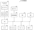
図11は、本実施形態に係る携帯電話機300の構成を示す機能ブロック図である。携帯電話機300は、CPU310と、RAM312と、ROM311と、カメラ313と、マイクロフォン314と、スピーカ315と、操作キー316と、表示パネル318と、表示制御回路309と、タッチパネルシステム301とを備えている。各構成要素は、相互にデータバスによって接続されている。
FIG. 11 is a functional block diagram showing the configuration of the mobile phone 300 according to the present embodiment. The cellular phone 300 includes a
CPU310は、携帯電話機300の動作を制御する。CPU310は、たとえばROM311に格納されたプログラムを実行する。操作キー316は、ユーザによる携帯電話機300への指示の入力を受ける。RAM312は、CPU310によるプログラムの実行により生成されたデータ、または操作キー316を介して入力されたデータを揮発的に格納する。ROM311は、データを不揮発的に格納する。
また、ROM311は、EPROM(Erasable Programmabe Read−Only Memory)またはフラッシュメモリなどの書込みおよび消去が可能なROMである。また、図11には示していないが、携帯電話機300が、他の電子機器に有線により接続するためのインターフェイス(IF)を備える構成としてもよい。
The
カメラ313は、ユーザの操作キー316の操作に応じて、被写体を撮影する。なお、撮影された被写体の画像データは、RAM312や外部メモリ(たとえば、メモリカード)に格納される。マイクロフォン314は、ユーザの音声の入力を受付ける。携帯電話機300は、当該入力された音声(アナログデータ)をデジタル化する。そして、携帯電話機300は、通信相手(たとえば、他の携帯電話機)にデジタル化した音声を送る。スピーカ315は、例えば、RAM312に記憶された音楽データなどに基づく音を出力する。
The
タッチパネルシステム301は、タッチパネル302とタッチパネルコントローラ303とを有している。CPU310は、タッチパネルシステム301の動作を制御する。CPU310は、例えばROM311に記憶されたプログラムを実行する。RAM312は、CPU310によるプログラムの実行により生成されたデータを揮発的に格納する。ROM311は、データを不揮発的に格納する。
The
表示パネル318は、表示制御回路309により、ROM311、RAM312に格納されている画像を表示する。表示パネル318は、タッチパネル302に重ねられているか、タッチパネル302を内蔵している。
The
本発明は上述した実施形態に限定されるものではなく、請求項に示した範囲で種々の変更が可能であり、上記実施形態にそれぞれ開示された技術的手段を適宜組み合わせて得られる他の実施形態についても本発明の技術的範囲に含まれる。 The present invention is not limited to the above-described embodiments, and various modifications are possible within the scope of the claims, and other embodiments obtained by appropriately combining the technical means disclosed in the above-described embodiments. The form is also included in the technical scope of the present invention.
本発明は、マトリックス状に構成された静電容量の容量値を推定または検出する線形系係数推定方法及びそれを用いた集積回路、タッチパネルシステム、及び電子機器に使用することができる。 INDUSTRIAL APPLICABILITY The present invention can be used for a linear system coefficient estimation method that estimates or detects capacitance values of capacitances configured in a matrix, and an integrated circuit, a touch panel system, and an electronic device using the same.
100、301 タッチパネルシステム
101 フィルタ(ノイズ除去部、離散時間フィルタ)
103、303 タッチパネルコントローラ(集積回路)
104 駆動部
105 推定部
106 増幅器
107 オペアンプ
108 遅延器(遅延部)
109 減算器(減算部)
200 フィルタ(ノイズ除去部、適応フィルタ)
201 遅延素子
202 可変ゲイン部
203 係数計算部
300 携帯電話機(電子機器)
302 タッチパネル
309 表示制御回路
310 CPU
311 ROM
312 RAM
313 カメラ
314 マイクロフォン
315 スピーカ
316 操作キー
318 表示パネル
806 増幅器(線形和信号取得部)
2000 フィルタ(ノイズ除去部、離散時間フィルタ、適応フィルタ)
MC M系列による符号系列
S1〜S8 信号
P1〜P3 容量パターン
100, 301
103, 303 Touch panel controller (integrated circuit)
104
108 delay unit (delay unit)
109 Subtractor (subtraction unit)
200 filter (noise removal unit, adaptive filter)
201 Delay Element 202
302
311 ROM
312 RAM
806 amplifier (linear sum signal acquisition unit)
2000 filter (noise removal unit, discrete time filter, adaptive filter)
Code sequence by MCM sequence S1-S8 signal P1-P3 capacity pattern
Claims (10)
前記ノイズ除去部が、前記線形和信号取得部により得られた前記N個の線形和信号に重畳したノイズを、前記線形和信号をフィルタリングすることによって除去するノイズ除去工程と、
前記推定部が、前記ノイズ除去工程によりノイズを除去された前記N個の線形和信号に基づく信号と、前記N個のM次元ベクトルとの内積演算により前記M個の静電容量値を推定する推定工程とを包含することを特徴とする静電容量値推定方法。 A drive unit that drives M capacitances existing at the intersections of the sense line of the touch panel and M drive lines (M is a plurality) in parallel based on N (N is a plurality) M-dimensional vectors; A linear sum signal acquisition unit that receives N linear sum signals based on the charge of the capacitance, a noise removal unit that removes noise of the N linear sum signals, and a signal based on the N linear sum signals wherein the N number of the touch panel system with an integrated circuit having an estimation unit for the inner product operation of the M-dimensional vector estimates the M capacitance value, the static to estimate the M capacitance value A method for estimating a capacitance value ,
Wherein the noise removal unit, the noise superimposed on the previous SL N linear sum signal obtained by the linear sum signal acquiring unit, a noise removal step of removing by filtering the linear sum signal,
The estimation unit estimates the M capacitance values by an inner product operation of a signal based on the N linear sum signals from which noise has been removed by the noise removal step and the N M-dimensional vectors. A capacitance value estimation method comprising: an estimation step.
前記ノイズ除去工程において、(i)前記遅延部は、前記線形和信号取得部からの前記線形和信号を遅延させて出力し、(ii)前記減算部は、前記線形和信号取得部からの前記線形和信号から、前記遅延部から出力される線形和信号を減算することを特徴とする請求項1記載の静電容量値推定方法。 The noise removing unit includes a discrete time filter including a delay unit and a subtraction unit,
Oite the noise removing step, (i) the delay unit, said from linear sum signal acquisition unit linear sum signal is delayed output, (ii) the subtraction unit, from the linear sum signal acquisition unit The capacitance value estimation method according to claim 1 , wherein a linear sum signal output from the delay unit is subtracted from the linear sum signal .
前記駆動部は、符号長NのM系列に基づくN個の符号系列から、上記遅延部により遅延された所定のクロック数に対応する符号系列が含まれないようにK個の符号系列(K<N)を選択して、前記N個のM次元ベクトルを構成することを特徴とする請求項2記載の静電容量値推定方法。 The delay unit is configured to delay the linear sum signal obtained from the linear sum signal acquisition unit by a predetermined number of clocks,
The driving unit includes K code sequences (K <) so that a code sequence corresponding to a predetermined number of clocks delayed by the delay unit is not included from N code sequences based on an M sequence having a code length of N. 3. The method of estimating a capacitance value according to claim 2 , wherein N) is selected to constitute the N M-dimensional vectors .
前記ノイズ除去工程において、(i)前記遅延素子は、前記線形和信号取得部から得られた前記線形和信号を遅延させた出力信号を出力し、(ii)前記係数計算部は、前記線形和信号取得部により得られた前記N個の線形和信号と前記遅延素子からの前記出力信号との相関を計算し、(iii)前記可変ゲイン部は、前記係数計算部による前記相関の計算結果に応じて、前記遅延素子からの前記出力信号に対してゲインを与え、(iv)前記減算部は、前記線形和信号取得部からの前記線形和信号から、前記可変ゲイン部によりゲインを与えられた前記出力信号を減算することを特徴とする請求項1記載の静電容量値推定方法。 The noise removing unit includes an adaptive filter including a delay element, a coefficient calculating unit, a variable gain unit, and a subtracting unit,
Oite the noise removing step, (i) the delay element, the linear sum outputs an output signal obtained by delaying the linear sum signal obtained from the signal acquisition unit, (ii) the coefficient calculator, the A correlation between the N linear sum signals obtained by the linear sum signal acquisition unit and the output signal from the delay element is calculated; and (iii) the variable gain unit calculates the correlation by the coefficient calculation unit. According to the result, a gain is given to the output signal from the delay element, and (iv) the subtractor gives a gain from the linear sum signal from the linear sum signal acquisition unit by the variable gain unit. 2. The capacitance value estimation method according to claim 1 , wherein the output signal is subtracted .
前記線形和信号取得部により得られた前記N個の線形和信号に重畳したノイズを、前記線形和信号をフィルタリングすることによって除去するノイズ除去部と、
前記ノイズ除去部によりノイズを除去されたN個の線形和信号に基づく信号と、前記N個のM次元ベクトルとの内積演算により前記M個の静電容量値を推定する推定部とをさらに備えたことを特徴とする集積回路。 A drive unit that drives M capacitances existing at the intersections of the sense line of the touch panel and M drive lines (M is a plurality) in parallel based on N (N is a plurality) M-dimensional vectors; An integrated circuit comprising a linear sum signal acquisition unit for receiving N linear sum signals based on the charge of the capacitance ,
A noise removing unit that removes by the noise superimposed on the previous SL N linear sum signal obtained by the linear sum signal acquisition unit, for filtering the linear sum signal,
A signal based on the N linear sum signal removed of noise by the pre-Symbol noise removing unit, and a estimation unit that estimates the M capacitance value by the inner product operation between the N M-dimensional vector further integrated circuit characterized by comprising.
前記駆動部は、符号長NのM系列に基づくN個の符号系列から、上記遅延部により遅延された所定の遅延クロック数に対応する符号系列が含まれないようにK個の符号系列(K<N)を選択して、前記N個のM次元ベクトルを構成することを特徴とする請求項6記載の集積回路。 The delay unit delays the linear sum signal obtained from the linear sum signal acquisition unit by a predetermined number of clocks,
The driving unit includes K code sequences (K) such that a code sequence corresponding to a predetermined number of delay clocks delayed by the delay unit is not included from N code sequences based on an M sequence having a code length of N. 7. The integrated circuit according to claim 6 , wherein <N) is selected to constitute the N M-dimensional vectors .
前記センスラインと前記M本のドライブラインとを有する前記タッチパネルとを備え、
前記集積回路は、前記M本のドライブラインと前記センスラインとの交点の前記静電容量が有するM個の静電容量値を推定することを特徴とするタッチパネルシステム。 An integrated circuit according to any one of claims 5 to 8,
The touch panel having the sense line and the M drive lines ;
The touch panel system , wherein the integrated circuit estimates M capacitance values of the capacitance at an intersection of the M drive lines and the sense lines .
前記センスラインと前記M本のドライブラインとを有する前記タッチパネルと、
前記タッチパネルに重ねられているか、前記タッチパネルを内蔵した表示パネルとを備え、
前記集積回路は、前記M本のドライブラインと前記センスラインとの交点の前記静電容量が有するM個の静電容量値を推定することを特徴とする電子機器。 An integrated circuit according to any one of claims 5 to 8,
The touch panel having the sense line and the M drive lines ;
It is overlaid on the touch panel or comprises a display panel incorporating the touch panel ,
The electronic apparatus is characterized in that the integrated circuit estimates M capacitance values of the capacitance at the intersection of the M drive lines and the sense lines .
Priority Applications (4)
| Application Number | Priority Date | Filing Date | Title |
|---|---|---|---|
| JP2012002600A JP5490828B2 (en) | 2012-01-10 | 2012-01-10 | Linear system coefficient estimation method, integrated circuit using the same, touch panel system, and electronic device |
| PCT/JP2013/050246 WO2013105584A1 (en) | 2012-01-10 | 2013-01-09 | Linear system coefficient estimation method, integrated circuit employing same, touch panel system, and electronic apparatus |
| CN201380004869.7A CN104094201A (en) | 2012-01-10 | 2013-01-09 | Linear system coefficient estimation method, integrated circuit employing same, touch panel system, and electronic apparatus |
| US14/370,889 US9189118B2 (en) | 2012-01-10 | 2013-01-09 | Linear system coefficient estimation method, integrated circuit employing same, touch panel system, and electronic apparatus |
Applications Claiming Priority (1)
| Application Number | Priority Date | Filing Date | Title |
|---|---|---|---|
| JP2012002600A JP5490828B2 (en) | 2012-01-10 | 2012-01-10 | Linear system coefficient estimation method, integrated circuit using the same, touch panel system, and electronic device |
Publications (2)
| Publication Number | Publication Date |
|---|---|
| JP2013142993A JP2013142993A (en) | 2013-07-22 |
| JP5490828B2 true JP5490828B2 (en) | 2014-05-14 |
Family
ID=48781528
Family Applications (1)
| Application Number | Title | Priority Date | Filing Date |
|---|---|---|---|
| JP2012002600A Active JP5490828B2 (en) | 2012-01-10 | 2012-01-10 | Linear system coefficient estimation method, integrated circuit using the same, touch panel system, and electronic device |
Country Status (4)
| Country | Link |
|---|---|
| US (1) | US9189118B2 (en) |
| JP (1) | JP5490828B2 (en) |
| CN (1) | CN104094201A (en) |
| WO (1) | WO2013105584A1 (en) |
Families Citing this family (9)
| Publication number | Priority date | Publication date | Assignee | Title |
|---|---|---|---|---|
| JP5973072B2 (en) * | 2013-06-20 | 2016-08-23 | シャープ株式会社 | Touch panel controller, integrated circuit, touch panel device, and electronic device |
| JP2015035053A (en) * | 2013-08-08 | 2015-02-19 | デクセリアルズ株式会社 | Electrostatic capacitance type touch panel |
| KR20170044155A (en) * | 2014-08-25 | 2017-04-24 | 쓰리엠 이노베이티브 프로퍼티즈 컴파니 | Capacitive-based touch apparatus and method with reduced interference |
| US9886136B2 (en) * | 2015-06-22 | 2018-02-06 | Samsung Electronics Co., Ltd. | Touch screen controller using adaptive filter control and touch screen system having the same |
| WO2017056900A1 (en) * | 2015-10-01 | 2017-04-06 | シャープ株式会社 | Capacitance detection method, position detection method, touch panel controller, and electronic device |
| JP6410699B2 (en) * | 2015-10-14 | 2018-10-24 | アルプス電気株式会社 | Input device, input device control method, and program for causing computer to execute input device control method |
| US9740356B1 (en) * | 2016-02-05 | 2017-08-22 | Pixart Imaging Inc. | Capacitive touch system using differential sensing and operating method thereof |
| US11768560B2 (en) | 2018-12-21 | 2023-09-26 | Synaptics Incorporated | System and method for reducing display interference |
| US11294505B2 (en) * | 2019-09-27 | 2022-04-05 | Synaptics Incorporated | Display interference mitigation |
Family Cites Families (14)
| Publication number | Priority date | Publication date | Assignee | Title |
|---|---|---|---|---|
| JPS63304313A (en) * | 1987-06-04 | 1988-12-12 | Sony Tektronix Corp | Touch position measuring method and touch panel device |
| JP3434415B2 (en) * | 1996-07-05 | 2003-08-11 | アルプス電気株式会社 | Coordinate input device |
| JP4364609B2 (en) | 2003-11-25 | 2009-11-18 | アルプス電気株式会社 | Capacitance detection circuit and fingerprint sensor using the same |
| WO2005091677A1 (en) * | 2004-03-22 | 2005-09-29 | Toa Corporation | Multi-channel system identification device |
| JP4453710B2 (en) * | 2007-03-19 | 2010-04-21 | セイコーエプソン株式会社 | Liquid crystal device, electronic apparatus and position detection method |
| US20110043478A1 (en) * | 2008-02-27 | 2011-02-24 | Kenichi Matsushima | Proximity detection device and proximity detection method |
| TWI420374B (en) * | 2008-09-08 | 2013-12-21 | Innolux Corp | Sensing circuit for capacitive touch panel and electronic device using the same |
| US8605037B2 (en) * | 2008-10-21 | 2013-12-10 | Atmel Corporation | Noise reduction in capacitive touch sensors |
| US8947373B2 (en) * | 2009-10-20 | 2015-02-03 | Cypress Semiconductor Corporation | Method and apparatus for reducing coupled noise influence in touch screen controllers |
| JP5361688B2 (en) | 2009-12-04 | 2013-12-04 | Udトラックス株式会社 | Exhaust purification device |
| JP5295090B2 (en) * | 2009-12-18 | 2013-09-18 | 株式会社ワコム | Indicator detection device |
| CN102156594B (en) * | 2010-02-12 | 2013-08-21 | 联咏科技股份有限公司 | Touch-sensing system, capacitance sensing circuit and capacitance sensing method |
| US9244569B2 (en) * | 2010-03-31 | 2016-01-26 | Stmicroelectronics Asia Pacific Pte Ltd | Capacitive sensing analog front end |
| KR20140026377A (en) * | 2011-02-07 | 2014-03-05 | 사이프레스 세미컨덕터 코포레이션 | Noise filtering devices, systems and methods for capacitance sensing devices |
-
2012
- 2012-01-10 JP JP2012002600A patent/JP5490828B2/en active Active
-
2013
- 2013-01-09 CN CN201380004869.7A patent/CN104094201A/en active Pending
- 2013-01-09 WO PCT/JP2013/050246 patent/WO2013105584A1/en active Application Filing
- 2013-01-09 US US14/370,889 patent/US9189118B2/en not_active Expired - Fee Related
Also Published As
| Publication number | Publication date |
|---|---|
| JP2013142993A (en) | 2013-07-22 |
| US9189118B2 (en) | 2015-11-17 |
| WO2013105584A1 (en) | 2013-07-18 |
| CN104094201A (en) | 2014-10-08 |
| US20150002463A1 (en) | 2015-01-01 |
Similar Documents
| Publication | Publication Date | Title |
|---|---|---|
| JP5490828B2 (en) | Linear system coefficient estimation method, integrated circuit using the same, touch panel system, and electronic device | |
| JP5341224B2 (en) | Touch panel controller, integrated circuit, touch panel system, and electronic device | |
| CN102262490B (en) | For using the noise cancellation technique of the capacitance touch screen controller of differential sensing | |
| TWI476650B (en) | Linear system coefficient estimating method, linear device column value estimating method, capacitance detecting method, integrated circuit, touch sensor system, and electronic device | |
| KR101441218B1 (en) | Touch sensor panel negative pixel compensation | |
| JP5740534B2 (en) | Signal processing system, touch panel controller, and touch panel system and electronic device using the same | |
| KR102043691B1 (en) | Touch detection method and touch detection system | |
| TWI514224B (en) | Touch sensor system and electronic device | |
| TW201305874A (en) | Touch panel system and electronic device | |
| CN102576543A (en) | Multi-input noise suppresion device, multi-input noise suppression method, program, and integrated circuit | |
| JP5973072B2 (en) | Touch panel controller, integrated circuit, touch panel device, and electronic device | |
| JP5989906B2 (en) | Touch panel controller, integrated circuit, and electronic device | |
| CN109524018B (en) | Echo processing method and device | |
| JP5969127B2 (en) | Touch panel controller and electronic device | |
| CN109785853B (en) | Echo cancellation method, device, system and storage medium | |
| JP5989937B2 (en) | Signal processing system, touch panel system, and electronic device | |
| JP2014006746A (en) | Touch panel controller, integrated circuit, touch panel unit, and electronic device | |
| JP6271732B2 (en) | Capacitance value distribution detection circuit, touch panel system, and electronic device | |
| JP2013149223A (en) | Linear system coefficient estimation method and integrated circuit using the same, touch panel device and electronic equipment | |
| JP2015007912A (en) | Touch panel controller and electronic device | |
| JP2013127680A (en) | Linear system coefficient estimating method, integrated circuit, touch panel device, and electronic device | |
| JP5449461B2 (en) | Touch panel controller, integrated circuit using the same, touch panel device, and electronic device | |
| WO2014129091A1 (en) | Touch panel controller, integrated circuit, touch panel device, and electronic apparatus | |
| CN113903351A (en) | Echo cancellation method, device, equipment and storage medium | |
| JP2015153109A (en) | touch panel controller, touch panel device, and electronic equipment |
Legal Events
| Date | Code | Title | Description |
|---|---|---|---|
| A131 | Notification of reasons for refusal |
Free format text: JAPANESE INTERMEDIATE CODE: A131 Effective date: 20130416 |
|
| A521 | Written amendment |
Free format text: JAPANESE INTERMEDIATE CODE: A523 Effective date: 20130613 |
|
| TRDD | Decision of grant or rejection written | ||
| A01 | Written decision to grant a patent or to grant a registration (utility model) |
Free format text: JAPANESE INTERMEDIATE CODE: A01 Effective date: 20140128 |
|
| A61 | First payment of annual fees (during grant procedure) |
Free format text: JAPANESE INTERMEDIATE CODE: A61 Effective date: 20140226 |
|
| R150 | Certificate of patent or registration of utility model |
Ref document number: 5490828 Country of ref document: JP Free format text: JAPANESE INTERMEDIATE CODE: R150 |