JP5488877B2 - Electric tool - Google Patents
Electric tool Download PDFInfo
- Publication number
- JP5488877B2 JP5488877B2 JP2009215124A JP2009215124A JP5488877B2 JP 5488877 B2 JP5488877 B2 JP 5488877B2 JP 2009215124 A JP2009215124 A JP 2009215124A JP 2009215124 A JP2009215124 A JP 2009215124A JP 5488877 B2 JP5488877 B2 JP 5488877B2
- Authority
- JP
- Japan
- Prior art keywords
- battery
- voltage
- battery pack
- switching element
- microcomputer
- Prior art date
- Legal status (The legal status is an assumption and is not a legal conclusion. Google has not performed a legal analysis and makes no representation as to the accuracy of the status listed.)
- Active
Links
Images


Classifications
-
- H—ELECTRICITY
- H01—ELECTRIC ELEMENTS
- H01M—PROCESSES OR MEANS, e.g. BATTERIES, FOR THE DIRECT CONVERSION OF CHEMICAL ENERGY INTO ELECTRICAL ENERGY
- H01M10/00—Secondary cells; Manufacture thereof
- H01M10/42—Methods or arrangements for servicing or maintenance of secondary cells or secondary half-cells
- H01M10/48—Accumulators combined with arrangements for measuring, testing or indicating the condition of cells, e.g. the level or density of the electrolyte
- H01M10/486—Accumulators combined with arrangements for measuring, testing or indicating the condition of cells, e.g. the level or density of the electrolyte for measuring temperature
-
- B—PERFORMING OPERATIONS; TRANSPORTING
- B25—HAND TOOLS; PORTABLE POWER-DRIVEN TOOLS; MANIPULATORS
- B25B—TOOLS OR BENCH DEVICES NOT OTHERWISE PROVIDED FOR, FOR FASTENING, CONNECTING, DISENGAGING OR HOLDING
- B25B21/00—Portable power-driven screw or nut setting or loosening tools; Attachments for drilling apparatus serving the same purpose
-
- H—ELECTRICITY
- H01—ELECTRIC ELEMENTS
- H01M—PROCESSES OR MEANS, e.g. BATTERIES, FOR THE DIRECT CONVERSION OF CHEMICAL ENERGY INTO ELECTRICAL ENERGY
- H01M10/00—Secondary cells; Manufacture thereof
- H01M10/42—Methods or arrangements for servicing or maintenance of secondary cells or secondary half-cells
- H01M10/425—Structural combination with electronic components, e.g. electronic circuits integrated to the outside of the casing
-
- H—ELECTRICITY
- H01—ELECTRIC ELEMENTS
- H01M—PROCESSES OR MEANS, e.g. BATTERIES, FOR THE DIRECT CONVERSION OF CHEMICAL ENERGY INTO ELECTRICAL ENERGY
- H01M10/00—Secondary cells; Manufacture thereof
- H01M10/42—Methods or arrangements for servicing or maintenance of secondary cells or secondary half-cells
- H01M10/48—Accumulators combined with arrangements for measuring, testing or indicating the condition of cells, e.g. the level or density of the electrolyte
- H01M10/482—Accumulators combined with arrangements for measuring, testing or indicating the condition of cells, e.g. the level or density of the electrolyte for several batteries or cells simultaneously or sequentially
-
- H—ELECTRICITY
- H01—ELECTRIC ELEMENTS
- H01M—PROCESSES OR MEANS, e.g. BATTERIES, FOR THE DIRECT CONVERSION OF CHEMICAL ENERGY INTO ELECTRICAL ENERGY
- H01M10/00—Secondary cells; Manufacture thereof
- H01M10/05—Accumulators with non-aqueous electrolyte
- H01M10/052—Li-accumulators
-
- Y—GENERAL TAGGING OF NEW TECHNOLOGICAL DEVELOPMENTS; GENERAL TAGGING OF CROSS-SECTIONAL TECHNOLOGIES SPANNING OVER SEVERAL SECTIONS OF THE IPC; TECHNICAL SUBJECTS COVERED BY FORMER USPC CROSS-REFERENCE ART COLLECTIONS [XRACs] AND DIGESTS
- Y02—TECHNOLOGIES OR APPLICATIONS FOR MITIGATION OR ADAPTATION AGAINST CLIMATE CHANGE
- Y02E—REDUCTION OF GREENHOUSE GAS [GHG] EMISSIONS, RELATED TO ENERGY GENERATION, TRANSMISSION OR DISTRIBUTION
- Y02E60/00—Enabling technologies; Technologies with a potential or indirect contribution to GHG emissions mitigation
- Y02E60/10—Energy storage using batteries
Landscapes
- Engineering & Computer Science (AREA)
- Manufacturing & Machinery (AREA)
- Chemical & Material Sciences (AREA)
- Chemical Kinetics & Catalysis (AREA)
- Electrochemistry (AREA)
- General Chemical & Material Sciences (AREA)
- Mechanical Engineering (AREA)
- Microelectronics & Electronic Packaging (AREA)
- Charge And Discharge Circuits For Batteries Or The Like (AREA)
- Secondary Cells (AREA)
Description
本発明は、複数の2次電池からなる電池パックを用いた電動工具に関する。 The present invention relates to an electric tool using a battery pack composed of a plurality of secondary batteries.
コードレス電動工具を駆動する電源として、ニッケル水素電池やニッケルカドミウム電池(以下、ニカド電池と称す)、或いは、高容量化および軽量化されたリチウムイオン電池が使用されている。セル公称電圧は、ニカド電池及びニッケル水素電池では1.2Vであるのに対して、リチウム電池のセル公称電圧は、3.6Vであり、ニッケル水素電池やニカド電池と比較すると約3倍高い。また、リチウム電池のエネルギ密度は、ニカド電池の約3倍という性能を持ちながらも小形軽量であるという特徴を有する。更に、リチウム電池は、放電効率も良く、比較的低温環境の中でも放電が可能であり、広い温度範囲で安定した電池電圧を得ることができる。 As a power source for driving the cordless electric tool, a nickel metal hydride battery, a nickel cadmium battery (hereinafter referred to as a nickel cadmium battery), or a lithium ion battery with a high capacity and a reduced weight is used. The nominal cell voltage is 1.2V for Ni-Cd and NiMH batteries, whereas the nominal cell voltage for Lithium batteries is 3.6V, which is about three times higher than that of Ni-MH and NiCd batteries. In addition, the energy density of the lithium battery has a feature that it is small and lightweight while having a performance of about three times that of the nickel-cadmium battery. Furthermore, the lithium battery has good discharge efficiency, can be discharged even in a relatively low temperature environment, and a stable battery voltage can be obtained in a wide temperature range.
一方、従来から用いられている定格電圧が12Vのコードレス電動工具に対し、多くの機種で、セル公称電圧が1.2Vのニカド電池又はニッケル水素電池を直列に10本接続した電池組が用いられている。この電池組をリチウム電池だけで構成する場合、リチウム電池のセル公称電圧は3.6Vであるために、リチウム電池を直列接続して得られる電圧は、3.6Vの倍数となって12Vにはならず、リチウム電池だけでは、コードレス電動工具に対応する電池パックを実現することができなかった。そこで、リチウム電池にニカド電池やニッケル水素電池を組み合わることにより、12Vの電池パックを構成する方法が提案されている(特許文献1)。 On the other hand, many cordless power tools with a rated voltage of 12V that have been used in the past use a battery set in which 10 nickel-cadmium batteries or nickel-metal hydride batteries with a nominal cell voltage of 1.2V are connected in series. ing. When this battery set is composed only of lithium batteries, the cell nominal voltage of the lithium batteries is 3.6V, so the voltage obtained by connecting lithium batteries in series is a multiple of 3.6V and is 12V. In addition, a battery pack corresponding to a cordless electric tool could not be realized with only a lithium battery. Then, the method of comprising a 12V battery pack by combining a nickel battery or a nickel metal hydride battery with a lithium battery has been proposed (Patent Document 1).
また、リチウム電池の出力電圧を変更するために、リチウム電池に電圧変換器を接続して電池パックからの出力電圧をセル公称電圧の3分の1に落とすことによって、リチウム電池に汎用の一次電池との互換性を持たせる方法も提案されている(特許文献2)。 In addition, in order to change the output voltage of the lithium battery, a voltage converter is connected to the lithium battery, and the output voltage from the battery pack is reduced to one third of the cell nominal voltage, so that the lithium battery is a general-purpose primary battery. There has also been proposed a method for providing compatibility with Japanese Patent Application Laid-Open No. 2003-228561.
リチウム電池は、電池の充電制御方式がニカド電池又はニッケル水素電池とは異なり、さらに、電池の容量や自己放電レベルも異なる。従って、リチウム電池にニカド電池又はニッケル水素電池を組み合わせて電池組を構成する場合、これらの違いに対処するために、複雑な充電制御や自己放電制御が必要になる。 The lithium battery is different from the nickel-cadmium battery or the nickel-metal hydride battery in the charge control system of the battery, and further has a different battery capacity and self-discharge level. Therefore, when a battery set is configured by combining a lithium battery with a nickel-cadmium battery or a nickel metal hydride battery, complicated charge control and self-discharge control are required to deal with these differences.
また、電動工具は、定格電圧が例えば12Vと汎用の一次電池の出力電圧と比較してかなり高い。従って、特許文献2記載の電圧変換器を内蔵する電池パックは、出力電圧が低いために、電動工具を駆動させることは難しい。
Moreover, the power tool has a rated voltage of, for example, 12 V, which is considerably higher than the output voltage of a general-purpose primary battery. Therefore, since the battery pack incorporating the voltage converter described in
本発明の目的は、上記問題点を鑑み、電動工具本体が使用可能な電圧を給電可能な電池パックを用いた電動工具を提供することである。 In view of the above problems, an object of the present invention is to provide a power tool using a battery pack capable of supplying a voltage that can be used by the power tool body.
請求項1記載電動工具は、複数の素電池からなる電池パックからの電力によって駆動されるモータを備えた電動工具であって、前記電池パックからの出力電圧を制御する制御部と、前記モータの使用可能電圧を示す電圧仕様情報を提供する電圧仕様情報提供手段と、を有し、前記制御部は、前記電圧仕様情報提供手段から前記電圧仕様情報を取得し、取得した前記電圧仕様情報に応じて前記出力電圧を制御することを特徴とする。
The electric tool according to
請求項2記載の電動工具は、請求項1に記載の電動工具であって、前記制御部は、前記素電池と直列に接続されるスイッチング素子と、前記スイッチング素子のスイッチング動作を制御する制御手段と、を備え、前記制御手段は、前記電圧仕様情報に応じて前記スイッチング動作を制御することを特徴とする。
The power tool according to
請求項3記載の電動工具は、請求項2に記載の電動工具であって、前記制御手段は、前記スイッチング素子のデューティ比を設定することを特徴とする。 A power tool according to a third aspect is the power tool according to the second aspect , wherein the control means sets a duty ratio of the switching element.
以下、本発明の実施の形態を添付図面を参照して説明する。 Embodiments of the present invention will be described below with reference to the accompanying drawings.
図1において、電動工具10は、電池パック101と、使用可能電圧がVSの電動工具本体201とからなる。
In FIG. 1, the
電池パック101は、電池組130と、保護回路102と、スイッチング手段140と、電源供給部150と、電池電圧検出手段160と、サーミスタ107と、電動工具電圧仕様検出部170と、制御手段としてのマイコン126とを有する。電池組130は、例えばリチウムイオン電池などの二次電池を素電池とする4つの電池セル103,104,105,106が直列に接続されて構成される。電池組130は、高電位側の端子Pが電池パック101の高電位側の出力端子THに接続され、低電位側の端子Qが電池パックの低電位側の出力端子TLに接続されている。
The
保護回路102は、各電池セル103,104,105,106のセル電圧を監視する。保護回路102は、電池組130の放電中に、少なくとも1つの電池セルのセル電圧が所定の電圧値以下になって過放電が生じていると判断する場合は、電池セルの過放電を知らせる過放電信号をマイコン126の入力ポートFに向けて出力する。また、保護回路102は、電池組130の充電中に少なくとも1つの電池セルに過充電が生じたときに、電池セルの過充電を知らせる過充電信号LEを出力する。
The
スイッチング手段140は、スイッチング素子124と抵抗122、123とからなる。スイッチング素子124は、電池組130の低電位側の端子Qと出力端子TLとの間に接続されている。スイッチング素子124は、FETからなり、マイコン126の出力ポートEから抵抗122を介して送られてくるスイッチング信号によって、電池組130の放電路の電動工具本体201への電気的接続を周期的にオン・オフさせるスイッチング動作を行う。
The
電源供給部150は、スイッチング素子110、111と、レギュレータ116と、ダイオード120、121と、抵抗108、109、118、119と、コンデンサ115,117とを有する。
The
スイッチング素子110、111は、それぞれFETからなる。スイッチング素子110は、端子Pとマイコン126の入力ポートAとの間に接続されて、電池組130からマイコン126への給電のオン・オフを行う。スイッチング素子110のゲート端子にハイレベルのスイッチング信号が印加されると、スイッチング素子110はオンになり、電池組130からの電力をマイコン126へ中継する。さらに、スイッチング素子110と入力ポートAとの間には、レギュレータ116が接続されている。レギュレータ116は、電池組130を電源とする所定電圧をマイコン126に出力する。
The
スイッチング素子111は、端子Qとスイッチング素子110のゲート端子との間に接続されて、スイッチング端子110のオン・オフを行う。スイッチング素子111は、端子TLを介してダイオード121及び抵抗119を介して流れ込む電流によって誘起される電圧、或いは、マイコン126の出力ポートDからダイオード120及び抵抗119を介して送られてくるハイレベルのスイッチング信号が印加されるとオンになる。
The
電池電圧検出手段160は、抵抗112、113とコンデンサ114とからなり、電池組130の電池電圧V0を検出する。検出された電池電圧は、マイコン126のポートBに入力される。
Battery voltage detecting means 160, a
サーミスタ107は、抵抗125と直列に接続されて、電池電圧V0を抵抗125と分圧することによって生成される電圧値を電池温度信号LSとして生成する。この電池温度信号LSは、マイコン126の入力ポートCに入力され、マイコン126は、電池パック101の温度を検出する。
The
電動工具電圧仕様検出部170は、抵抗127を有し、電動工具本体201の使用可能電圧VSに対応する電圧識別信号Aを生成する。
The power tool voltage
マイコン126は、電池組130の電池電圧V0に対するスイッチング素子124のスイッチング動作によって得られる電池パック101の平均出力電圧が、電動工具本体の使用可能電圧VSと一致するように、スイッチング素子124のスイッチング動作のデューティ比Rを設定する。そして、設定されたデューティ比Rに対応したスイッチング信号を出力ポートEからスイッチング素子124に向けて出力する。また、電池組130の放電の継続により電池組130の電池電圧V0が低下する場合は、デューティ比Rを変更させることによって、電池パック101の平均出力電圧を一定に維持する。
The
電池セルに過放電が生じた場合、マイコン126は、スイッチング素子124へのスイッチング信号をローレベルに変更してスイッチング素子124をオフにしてその状態を維持することによって、電池組130の放電を遮断する。このとき、同時に、マイコン126は、スイッチング素子111に対してローレベルの信号を出力してスイッチング素子111とスイッチング素子110とをオフにすることで、マイコン126自身への給電も遮断する。
When an overdischarge occurs in the battery cell, the
ダイオード128は、アノードが出力端子TLに接続されるように、出力端子TH,TLの間に接続されている。
一方、電動工具本体201は、高電位側の接続端子RHと、低電位側の接続端子RLとの間に、モータ202と、トリガースイッチ203とが直列に接続されている。接続端子RHは、電池パック101の出力端子THと接続され、接続端子RLは、電池パック101の出力単位THと接続される。さらに、電動工具本体201は、電圧仕様情報提供手段としての抵抗204を有し、抵抗204は、使用可能電圧としての電動工具本体201の電圧仕様VSに対応した抵抗値を有する。
On the other hand, in the electric
次に、電池パック101が電動工具本体201へ放電する動作について、図2のフローチャートに沿って説明する。
Next, the operation of discharging the
電池パック101が電動工具本体201に装着された後、電動工具本体201のトリガースイッチ203がオンとされると、電池組130から出力された電流は、出力端子TH、電動工具本体201の接続端子RH、モータ202、トリガスイッチ203を通過して、電池パック101の低電位側の出力端子TLに流れ込む(ステップ401)。このとき、スイッチング素子124は、オフ状態であるため、電流は、ダイオード121、抵抗器119を通ってスイッチング素子111のゲート端子に流れ込む。この電流によって誘起された電圧によって、スイッチング素子111はオン状態になる。
When the
スイッチング素子111がオン状態になると、それに伴ってスイッチング素子110もオン状態に切り替わり、レギュレータ116に電池電圧V0が入力される。レギュレータ116は、定電圧源であり、マイコン126に定電圧を供給する(ステップ402)。マイコン126は、給電の開始によって起動され、出力ポートDからダイオード120を介してスイッチング素子111のゲート端子にハイレベルの信号を出力して、スイッチング素子111のオン状態を維持する(ステップ403)。スイッチング素子111のオン状態の維持によって、スイッチング素子110のオン状態も維持され、マイコン126は、継続して電池組130の充放電を制御可能となる。
When the
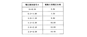
また、電池パック101が電動工具本体201に装着されることによって、電動工具仕様電圧検出部170の抵抗127と電動工具本体201の抵抗204とが直列に接続される。マイコン126は、電池電圧V0が直列接続された抵抗127、204によって分圧されて得られた電圧値を電圧識別信号Aとして入力ポートGを介して取り込む(ステップ404)。図3に、電圧識別信号Aの電圧値と、電動工具本体201の電圧仕様との関係の一例を示す。例えば、電圧識別信号Aの電圧値が0〜0.5Vであった場合、マイコン126は、電圧仕様が3.6Vの電動工具本体201が装着されたと判別する。また、電圧識別信号Aの電圧値が2.5〜3.0Vであった場合は、マイコン126は、14.4V用の電動工具本体201が装着されたと判別する。
In addition, when the
次に、マイコン126は、電池組130の電池電圧V0を測定する(ステップ405)。マイコン126は、ステップ404で検出した電動工具本体201の電圧仕様VSとステップ405で検出した現在の電池組130の電池電圧V0とから、スイッチング素子124のスイッチング動作のデューティ比を以下の式を用いて算出する(ステップ406)。
Next, the
デューティ比=(電動工具本体の電圧仕様/実際の電池組の電池電圧)×100% Duty ratio = (Voltage specification of power tool body / Battery voltage of actual battery set) x 100%
次に、マイコン126は、ステップ406で設定したデューティ比のスイッチング信号を、抵抗器122を介してスイッチング素子124のゲート端子に入力する。このスイッチング信号によって、スイッチング素子124は、スイッチング動作を開始し、スイッチング信号がハイレベルの時はオンとなり、ローレベルの時はオフとなる。このスイッチング動作によって、電池組130からの出力電圧は、デューティ比に応じて平均化されて電動工具本体201に印加される(ステップ407)。このとき、電池パック101から出力される平均電圧は、電池電圧V0ではなく、電動工具本体201の電池仕様と一致する。
Next, the
次に、マイコン126は、保護回路102からの過放電信号の有無を検出する(ステップ408)。過放電信号が検出された場合は(ステップ408:YES)、ステップ411に進む。過放電信号が検出されない場合は(ステップ408:NO)、ステップ409に進む。
Next, the
ステップ409で、マイコン126は、電池パック101の温度を測定する。電池パック101の温度が所定値以上である場合は(ステップ409:YES)、ステップ411に進む。電池パック101の温度が所定値未満である場合は(ステップ409:NO)、ステップ410に進む。
In
ステップ410において、マイコン126は、スイッチング素子124のスイッチング動作を開始してから1時間が経過したかどうかの判別を行う。スイッチング動作を開始してから1時間が経過しているときは(ステップ410:YES)、ステップ411に進む。スイッチング動作を開始してから1時間を経過していないときは(ステップ410:NO)、ステップ403へ戻り、電池パック101の出力電圧の制御及び電池パック101の状態の監視を継続する。
In
一方、マイコン126の判別がステップ411に進んだ場合は、スイッチング素子124をオフ状態にして電池パック101から電動工具本体201への放電を停止する(ステップ411)。さらに、マイコン126は、スイッチング素子111に出力していたハイレベルの信号をローレベルの信号に切り替えることによって、スイッチング素子111をオフにする(ステップ412)。スイッチング素子111のオフにより、スイッチング素子110もオフになるので、マイコン126への給電が停止される。
On the other hand, when the determination by the
なお、図2に示すフローチャートにおいて、ステップ403からステップ412までの各ステップは、マイコン126によって行われる。
In the flowchart shown in FIG. 2, each step from
次に、図4に、電池パック101を充電する充電器301を示す。充電器301は、主に、電池パック101に充電電流を供給する充電回路302と、電池パック101への充電動作を制御する制御回路303とを有する。制御回路303は、電池パック101から送られてくる過充電信号LEと電池温度信号LSとに基づいて、充電中の電池パック101の過充電の発生と温度とを監視する。保護回路102から過充電信号LEが出力された時は、制御回路303は、直ちに充電回路302に信号を送って、電池パック101の充電を停止させる。
Next, FIG. 4 shows a
電池パック101の充電が開始されると、電池パック101の放電開始直後と同様に、スイッチング素子110がオンしてマイコン126が起動される。マイコン126は、電圧識別信号Aが入力されないことから、電池パック101が充電されていることを検知する。従って、スイッチング素子124のゲート端子に対して、ハイレベルの信号を出力して、スイッチング素子をオンにしてその状態を維持させる。従って、電池組130と充電回路302とは電気的に接続されるので、電池パック101は充電される。他の構成としては、充電器の内部に、充電器であることを示す識別抵抗を設け、電池パック101が充電器に接続されたときには、端子Aから識別抵抗を読み取ることで、マイコン126は、充電器に接続されていると判断し、スイッチング素子124をオンするようにしてもよい。
When the charging of the
以上のように、電池パック101が装着された電動工具本体201から電圧仕様を取得して、電圧仕様及び電池組の実際の電池電圧から求められたデューティ比で、電池組130に直列接続されたスイッチング素子124をスイッチング動作させることにより、電池パックの平均出力電圧を、電動工具本体201の電圧仕様と一致させることができる。従って、電池パック101からの給電によって、電動工具本体201を駆動させることができる。従って、電池組130の電池電圧V0と、電動工具本体201の電圧仕様とが一致しない場合であっても、かかる電池パック101を電動工具本体201に装着して電池パック101からの給電によって、電動工具本体201を駆動させることができる。
As described above, the voltage specification is acquired from the
また、電池パック101の放電中は、断続的に電池電圧V0を検出し、電池電圧V0を検出する度にデューティ比Rを算出している。従って、放電の継続により電池電圧V0の降下が生じた場合であっても、デューティ比Rを変えることによって、電池パック101の平均出力電圧を一定に維持することができる。従って、電動工具本体201への定電圧の印加を維持できる。
Further, while the
さらに、電池パック101から電動工具本体201への放電がスイッチング素子124のオフによって停止されたとき、スイッチング素子110のオフによって、電池組130からマイコン126への給電も停止される。従って、電池パック101の未使用時における電池パック101の内部での電力消費を抑制できる。
Further, when the discharge from the
また、電池セル103,104,105,106の過放電、或いは電池パック101の温度が異常なほど高温に達した場合も、電池パック101の放電が停止されると共に、電池パック101内部での電力消費も抑制される。
In addition, when the
なお、上記実施例では、電池パック101は、電池組130と、保護回路102と、スイッチング手段140と、電源供給部150と、電池電圧検出手段160と、サーミスタ107と、電動工具電圧仕様検出部170と、マイコン126とを有していたが、この構成に代えて、図5に示すように構成することもできる。すなわち、電池パック101は、電池組130と、保護回路102と、サーミスタ107とを有し、電動工具本体201が、電源供給部150と、電池電圧検出手段160と、電動工具電圧仕様検出部170と、マイコン126とを有していても良い。電池パック101が、複数の電池セルの直列構成からなる場合であっても、電動工具本体201が自身の電圧仕様に、スイッチング素子124のスイッチング動作により電池パック101の出力平均電圧を調整することができるので、図1に示す構成と同様の作用及び効果を奏する。
In the above embodiment, the
また、上記実施例では、電池組130は、4つの電池セルが直列に接続された場合について説明したが、電池組の構成はこれに限られるものではない。この場合、図3に示した電圧識別信号Aの電圧値と電動工具本体の電圧仕様の関係も、電池パックのセル数に適した値に変更される。さらに、電池セルは、リチウムイオン電池に限らず、リチウムイオン電池に代えて別の種類の二次電池を用いることができる。 Moreover, although the battery set 130 demonstrated the case where the four battery cells were connected in series in the said Example, the structure of a battery set is not restricted to this. In this case, the relationship between the voltage value of the voltage identification signal A shown in FIG. 3 and the voltage specification of the power tool body is also changed to a value suitable for the number of cells of the battery pack. Furthermore, the battery cell is not limited to a lithium ion battery, and another type of secondary battery can be used instead of the lithium ion battery.
また、ステップS410における経過時間は、電動工具10の用途に応じて適宜に変更できる。
Further, the elapsed time in step S410 can be changed as appropriate according to the application of the
10 電動工具
101 電池パック
103、104、105、106 素電池
124 スイッチング素子
126 制御手段
130 電池組
201 電動工具本体
DESCRIPTION OF
Claims (3)
前記電池パックからの出力電圧を制御する制御部と、
前記モータの使用可能電圧を示す電圧仕様情報を提供する電圧仕様情報提供手段と、を有し、
前記制御部は、前記電圧仕様情報提供手段から前記電圧仕様情報を取得し、取得した前記電圧仕様情報に応じて前記出力電圧を制御することを特徴とする電動工具。 An electric tool comprising a motor driven by electric power from a battery pack comprising a plurality of unit cells,
A control unit for controlling an output voltage from the battery pack;
Voltage specification information providing means for providing voltage specification information indicating a usable voltage of the motor,
The said control part acquires the said voltage specification information from the said voltage specification information provision means, and controls the said output voltage according to the acquired said voltage specification information, The electric tool characterized by the above-mentioned.
前記制御手段は、前記電圧仕様情報に応じて前記スイッチング動作を制御することを特徴とする請求項1に記載の電動工具。 The control unit includes a switching element connected in series with the unit cell, and control means for controlling a switching operation of the switching element,
The power tool according to claim 1 , wherein the control unit controls the switching operation according to the voltage specification information.
Priority Applications (2)
| Application Number | Priority Date | Filing Date | Title |
|---|---|---|---|
| JP2009215124A JP5488877B2 (en) | 2009-09-17 | 2009-09-17 | Electric tool |
| PCT/JP2010/066461 WO2011034201A1 (en) | 2009-09-17 | 2010-09-15 | Battery pack and power tool using the same |
Applications Claiming Priority (1)
| Application Number | Priority Date | Filing Date | Title |
|---|---|---|---|
| JP2009215124A JP5488877B2 (en) | 2009-09-17 | 2009-09-17 | Electric tool |
Publications (3)
| Publication Number | Publication Date |
|---|---|
| JP2011067004A JP2011067004A (en) | 2011-03-31 |
| JP2011067004A5 JP2011067004A5 (en) | 2012-04-26 |
| JP5488877B2 true JP5488877B2 (en) | 2014-05-14 |
Family
ID=43304718
Family Applications (1)
| Application Number | Title | Priority Date | Filing Date |
|---|---|---|---|
| JP2009215124A Active JP5488877B2 (en) | 2009-09-17 | 2009-09-17 | Electric tool |
Country Status (2)
| Country | Link |
|---|---|
| JP (1) | JP5488877B2 (en) |
| WO (1) | WO2011034201A1 (en) |
Families Citing this family (14)
| Publication number | Priority date | Publication date | Assignee | Title |
|---|---|---|---|---|
| JP5956245B2 (en) * | 2012-05-11 | 2016-07-27 | 株式会社マキタ | Battery pack and electric device system |
| WO2014148228A1 (en) | 2013-03-22 | 2014-09-25 | 日立工機株式会社 | Cell pack and electrical device |
| CN103354351B (en) * | 2013-07-04 | 2015-12-02 | 国家电网公司 | A kind of voltage protection method for single lead-acid battery |
| CN103354350B (en) * | 2013-07-04 | 2016-08-10 | 国家电网公司 | A kind of voltage protection method for single lithium battery |
| CN104007394B (en) * | 2014-05-23 | 2017-03-22 | 国网河南省电力公司漯河供电公司 | Storage battery discharging instrument and discharging current regulating method thereof |
| EP3235119B1 (en) * | 2014-12-18 | 2021-10-13 | Black & Decker Inc. | Control scheme to increase power output of a power tool using conduction band and advance angle |
| CN106299180B (en) * | 2015-06-24 | 2019-03-08 | 南京德朔实业有限公司 | The combination of electric tool and battery pack |
| JP6143819B2 (en) * | 2015-09-02 | 2017-06-07 | Fdk株式会社 | Constant voltage circuit and power supply system |
| WO2017122450A1 (en) | 2016-01-15 | 2017-07-20 | ノバルス株式会社 | Battery-shaped power supply device equipped with wireless communication function |
| JP6977324B2 (en) * | 2017-06-16 | 2021-12-08 | 工機ホールディングス株式会社 | Battery packs and electrical equipment using battery packs |
| CN109946532B (en) * | 2017-12-21 | 2024-03-19 | 南京泉峰科技有限公司 | Diagnostic device and diagnostic method for tool system components |
| JP6923068B2 (en) * | 2018-03-09 | 2021-08-18 | 工機ホールディングス株式会社 | Power supply unit, and system consisting of power supply unit and power tool |
| CN114655071A (en) * | 2022-02-18 | 2022-06-24 | 华为数字能源技术有限公司 | Battery, battery control method and electric vehicle |
| CN114578245B (en) * | 2022-05-06 | 2022-07-08 | 四川富临新能源科技有限公司 | Device and method for rapidly detecting self-discharge rate of lithium iron phosphate lithium ion battery |
Family Cites Families (11)
| Publication number | Priority date | Publication date | Assignee | Title |
|---|---|---|---|---|
| JP3212910B2 (en) * | 1997-06-19 | 2001-09-25 | シャープ株式会社 | Electric vacuum cleaner |
| JPH11185824A (en) | 1997-10-15 | 1999-07-09 | Sony Corp | Primary battery compatible battery pack |
| JP2001129769A (en) * | 1999-10-29 | 2001-05-15 | Matsushita Electric Works Ltd | Power tool |
| JP4447182B2 (en) * | 2001-04-05 | 2010-04-07 | 株式会社マキタ | Battery powered power tool |
| JP3873648B2 (en) * | 2001-04-10 | 2007-01-24 | 日立工機株式会社 | DC power supply with charging function |
| JP4182795B2 (en) * | 2003-04-08 | 2008-11-19 | 船井電機株式会社 | Paper feed mechanism of printing device |
| EP1673828B1 (en) * | 2003-10-14 | 2013-05-08 | Black & Decker Inc. | Protection methods, protection circuits and protective devices for secondary batteries, a power tool, charger and battery pack adapted to provide protection against fault conditions in the battery pack |
| JP2005160233A (en) | 2003-11-26 | 2005-06-16 | Makita Corp | Battery pack and cell battery pack |
| JP4968624B2 (en) * | 2006-09-19 | 2012-07-04 | 日立工機株式会社 | Adapter, combination of battery pack and adapter, and electric tool equipped with them |
| JP5574138B2 (en) * | 2006-09-19 | 2014-08-20 | 日立工機株式会社 | Adapter, combination of battery pack and adapter, and electric tool equipped with them |
| JP2009089499A (en) * | 2007-09-28 | 2009-04-23 | Panasonic Electric Works Co Ltd | Charging type electric apparatus |
-
2009
- 2009-09-17 JP JP2009215124A patent/JP5488877B2/en active Active
-
2010
- 2010-09-15 WO PCT/JP2010/066461 patent/WO2011034201A1/en active Application Filing
Also Published As
| Publication number | Publication date |
|---|---|
| WO2011034201A1 (en) | 2011-03-24 |
| JP2011067004A (en) | 2011-03-31 |
Similar Documents
| Publication | Publication Date | Title |
|---|---|---|
| JP5488877B2 (en) | Electric tool | |
| EP2034585B1 (en) | System and Method for Re-initiating Charge Cycle for Battery Pack Left in a Charger | |
| EP3204998B1 (en) | Electrical energy storage device | |
| US7990109B2 (en) | Temperature and polarization voltage compensation system | |
| EP2645527A1 (en) | Battery pack | |
| JP5614572B2 (en) | Electric tools and battery packs | |
| JP3931446B2 (en) | Battery charge state adjustment device | |
| JP2003164066A (en) | Battery pack | |
| JP2001095158A (en) | Battery power unit and electric apparatus using the same | |
| JP2002044878A (en) | Battery charging apparatus and battery charging method | |
| WO2011122696A1 (en) | Battery pack and power tool using the same | |
| US20140159664A1 (en) | Method of manufacturing battery pack and battery pack | |
| EP1717926A2 (en) | Battery charger | |
| JP2020530751A (en) | Devices, battery systems and methods for controlling main and sub-batteries | |
| JP2015050833A (en) | Battery pack, power tool having the same, and charger | |
| JP2005160233A (en) | Battery pack and cell battery pack | |
| JP2007082304A (en) | Charger | |
| JP2008125199A (en) | Control method for battery pack | |
| JP2013201889A (en) | Vehicle and method of controlling the same | |
| KR20060078967A (en) | Balance charging control method of 2nd-series battery pack | |
| WO2012081296A1 (en) | Battery pack | |
| KR20170060849A (en) | Battery Pack and Electric Vehicle Including The Same | |
| JP2008131710A (en) | Power supply system, its control method, program for executing control method of power supply system, and medium recording program for executing control method of power supply system | |
| JP4479910B2 (en) | Charger | |
| JP2010016976A (en) | Charging system |
Legal Events
| Date | Code | Title | Description |
|---|---|---|---|
| A521 | Request for written amendment filed |
Free format text: JAPANESE INTERMEDIATE CODE: A523 Effective date: 20120312 |
|
| A621 | Written request for application examination |
Free format text: JAPANESE INTERMEDIATE CODE: A621 Effective date: 20120312 |
|
| A131 | Notification of reasons for refusal |
Free format text: JAPANESE INTERMEDIATE CODE: A131 Effective date: 20130507 |
|
| A521 | Request for written amendment filed |
Free format text: JAPANESE INTERMEDIATE CODE: A523 Effective date: 20130708 |
|
| A521 | Request for written amendment filed |
Free format text: JAPANESE INTERMEDIATE CODE: A523 Effective date: 20130716 |
|
| A131 | Notification of reasons for refusal |
Free format text: JAPANESE INTERMEDIATE CODE: A131 Effective date: 20130812 |
|
| A521 | Request for written amendment filed |
Free format text: JAPANESE INTERMEDIATE CODE: A523 Effective date: 20131007 |
|
| A131 | Notification of reasons for refusal |
Free format text: JAPANESE INTERMEDIATE CODE: A131 Effective date: 20131024 |
|
| A521 | Request for written amendment filed |
Free format text: JAPANESE INTERMEDIATE CODE: A523 Effective date: 20131219 |
|
| A131 | Notification of reasons for refusal |
Free format text: JAPANESE INTERMEDIATE CODE: A131 Effective date: 20140116 |
|
| A521 | Request for written amendment filed |
Free format text: JAPANESE INTERMEDIATE CODE: A523 Effective date: 20140116 |
|
| TRDD | Decision of grant or rejection written | ||
| A01 | Written decision to grant a patent or to grant a registration (utility model) |
Free format text: JAPANESE INTERMEDIATE CODE: A01 Effective date: 20140130 |
|
| A61 | First payment of annual fees (during grant procedure) |
Free format text: JAPANESE INTERMEDIATE CODE: A61 Effective date: 20140212 |
|
| R150 | Certificate of patent or registration of utility model |
Ref document number: 5488877 Country of ref document: JP Free format text: JAPANESE INTERMEDIATE CODE: R150 |
|
| S533 | Written request for registration of change of name |
Free format text: JAPANESE INTERMEDIATE CODE: R313533 |
|
| R350 | Written notification of registration of transfer |
Free format text: JAPANESE INTERMEDIATE CODE: R350 |