JP5482155B2 - Information communication system, connection setting device, and connection setting program - Google Patents
Information communication system, connection setting device, and connection setting program Download PDFInfo
- Publication number
- JP5482155B2 JP5482155B2 JP2009276325A JP2009276325A JP5482155B2 JP 5482155 B2 JP5482155 B2 JP 5482155B2 JP 2009276325 A JP2009276325 A JP 2009276325A JP 2009276325 A JP2009276325 A JP 2009276325A JP 5482155 B2 JP5482155 B2 JP 5482155B2
- Authority
- JP
- Japan
- Prior art keywords
- information
- connection port
- unit
- physical connection
- logical
- Prior art date
- Legal status (The legal status is an assumption and is not a legal conclusion. Google has not performed a legal analysis and makes no representation as to the accuracy of the status listed.)
- Expired - Fee Related
Links
Images


Classifications
-
- H—ELECTRICITY
- H04—ELECTRIC COMMUNICATION TECHNIQUE
- H04L—TRANSMISSION OF DIGITAL INFORMATION, e.g. TELEGRAPHIC COMMUNICATION
- H04L67/00—Network arrangements or protocols for supporting network services or applications
- H04L67/01—Protocols
- H04L67/10—Protocols in which an application is distributed across nodes in the network
- H04L67/1097—Protocols in which an application is distributed across nodes in the network for distributed storage of data in networks, e.g. transport arrangements for network file system [NFS], storage area networks [SAN] or network attached storage [NAS]
-
- G—PHYSICS
- G06—COMPUTING; CALCULATING OR COUNTING
- G06F—ELECTRIC DIGITAL DATA PROCESSING
- G06F3/00—Input arrangements for transferring data to be processed into a form capable of being handled by the computer; Output arrangements for transferring data from processing unit to output unit, e.g. interface arrangements
- G06F3/06—Digital input from, or digital output to, record carriers, e.g. RAID, emulated record carriers or networked record carriers
- G06F3/0601—Interfaces specially adapted for storage systems
- G06F3/0602—Interfaces specially adapted for storage systems specifically adapted to achieve a particular effect
- G06F3/0604—Improving or facilitating administration, e.g. storage management
- G06F3/0605—Improving or facilitating administration, e.g. storage management by facilitating the interaction with a user or administrator
-
- G—PHYSICS
- G06—COMPUTING; CALCULATING OR COUNTING
- G06F—ELECTRIC DIGITAL DATA PROCESSING
- G06F3/00—Input arrangements for transferring data to be processed into a form capable of being handled by the computer; Output arrangements for transferring data from processing unit to output unit, e.g. interface arrangements
- G06F3/06—Digital input from, or digital output to, record carriers, e.g. RAID, emulated record carriers or networked record carriers
- G06F3/0601—Interfaces specially adapted for storage systems
- G06F3/0628—Interfaces specially adapted for storage systems making use of a particular technique
- G06F3/0653—Monitoring storage devices or systems
-
- G—PHYSICS
- G06—COMPUTING; CALCULATING OR COUNTING
- G06F—ELECTRIC DIGITAL DATA PROCESSING
- G06F3/00—Input arrangements for transferring data to be processed into a form capable of being handled by the computer; Output arrangements for transferring data from processing unit to output unit, e.g. interface arrangements
- G06F3/06—Digital input from, or digital output to, record carriers, e.g. RAID, emulated record carriers or networked record carriers
- G06F3/0601—Interfaces specially adapted for storage systems
- G06F3/0668—Interfaces specially adapted for storage systems adopting a particular infrastructure
- G06F3/067—Distributed or networked storage systems, e.g. storage area networks [SAN], network attached storage [NAS]
-
- H—ELECTRICITY
- H04—ELECTRIC COMMUNICATION TECHNIQUE
- H04L—TRANSMISSION OF DIGITAL INFORMATION, e.g. TELEGRAPHIC COMMUNICATION
- H04L12/00—Data switching networks
- H04L12/64—Hybrid switching systems
- H04L12/6418—Hybrid transport
-
- G—PHYSICS
- G06—COMPUTING; CALCULATING OR COUNTING
- G06F—ELECTRIC DIGITAL DATA PROCESSING
- G06F2206/00—Indexing scheme related to dedicated interfaces for computers
- G06F2206/10—Indexing scheme related to storage interfaces for computers, indexing schema related to group G06F3/06
- G06F2206/1008—Graphical user interface [GUI]
Description
本件開示は、情報通信システム、接続設定装置、および接続設定プログラムに関する。 The present disclosure relates to an information communication system, a connection setting device, and a connection setting program.
従来より、ストレージ・エリア・ネットワーク(SAN:Storage Area Network)と称される、1つ以上のサーバ装置と1つ以上のストレージ装置をファイバチャネル(FC)スイッチを介して接続したネットワークが知られている。このSANは、ネットワーク上で情報通信を行うという意味で情報通信システムの一種となっている。また、このSAN上で用いられる技術としてゾーニングと称される技術が知られている(例えば、特許文献1参照。)。このゾーニングでは、FCスイッチに接続されている装置のFCポートがゾーンと呼ばれるグループに分けられる。このゾーンに属するFCポート同士の相互通信が許可されることで排他的なアクセスが実現される。 Conventionally, a network called a storage area network (SAN), in which one or more server devices and one or more storage devices are connected via a fiber channel (FC) switch, is known. Yes. This SAN is a kind of information communication system in the sense that information communication is performed on a network. A technique called zoning is known as a technique used on the SAN (see, for example, Patent Document 1). In this zoning, the FC ports of the devices connected to the FC switch are divided into groups called zones. Exclusive access is realized by allowing mutual communication between FC ports belonging to this zone.
SANやゾーニングに限られず、多くの近年の情報通信システムでは、単に通信用の通信線を装置間で物理的に接続しただけでは情報通信が実行できない。情報通信システムで情報通信が実行されるためには、情報通信システムを構成している装置に対して、情報通信の相手を登録することが必要となる。 In many recent information communication systems, not limited to SAN and zoning, information communication cannot be performed simply by physically connecting communication communication lines between devices. In order for information communication to be performed in the information communication system, it is necessary to register the information communication partner with respect to the devices constituting the information communication system.
しかし、このような登録を行うためには、情報通信システムに組み込まれる各装置の各通信ポートを特定する情報を入手して登録するという作業を伴う。そのため、情報通信システムが大型化かつ複雑化するにつれて、作業が煩雑化するとともに作業ミスの可能性も増加する。 However, such registration involves an operation of obtaining and registering information for specifying each communication port of each device incorporated in the information communication system. Therefore, as the information communication system becomes larger and complicated, the work becomes complicated and the possibility of work mistakes increases.
上記事情に鑑み、本件開示は、装置間の接続を効率的かつ確実に設定することができる情報通信システム、接続設定装置、および接続設定プログラムを提供することを目的とする。 In view of the above circumstances, it is an object of the present disclosure to provide an information communication system, a connection setting device, and a connection setting program that can efficiently and reliably set a connection between devices.
上記目的を達成する情報通信システムは、第1の情報通信装置と第2の情報通信装置と通信網とを備えている。この情報通信システムは、更に、上記目的を達成する接続設定装置も備えている。 An information communication system that achieves the above object includes a first information communication device, a second information communication device, and a communication network. The information communication system further includes a connection setting device that achieves the above object.
上記第1の情報通信装置は、第1の物理接続口と第1の通信部と第1の情報出力口とを備えたものである。この第1の物理接続口は、情報通信の通信線が物理的に接続されるものである。第1の通信部は、上記第1の物理接続口に接続された通信線を介して情報通信を行うものである。第1の情報出力口は、上記第1の物理接続口を特定する物理接続口情報を出力するものである。 The first information communication apparatus includes a first physical connection port, a first communication unit, and a first information output port. The first physical connection port is to which an information communication communication line is physically connected. The first communication unit performs information communication via a communication line connected to the first physical connection port. The first information output port outputs physical connection port information for specifying the first physical connection port.
上記第2の情報通信装置は、第2の物理接続口と論理接続口記憶部と対応被登録部と第2の通信部と第2の情報出力口とを備えたものである。第2の物理接続口は、情報通信の通信線が物理的に接続されるものである。論理接続口記憶部は、論理的な存在としての論理接続口を特定する論理接続口情報を記憶したものである。この論理接続口は、上記第2の物理接続口に物理的に接続される通信線に対する論理的な接続先となる。対応被登録部は、上記論理接続口情報が特定する論理接続口と上記第1の物理接続口との論理的対応が登録されるものである。第2の通信部は、上記対応登録部に論理的対応が登録されている第1の物理接続口を通信相手として、上記第2の物理接続口に接続された通信線を介して情報通信を行うものである。第2の情報出力口は、上記論理接続口記憶部に記憶されている論理接続口情報を出力するものである。 The second information communication apparatus includes a second physical connection port, a logical connection port storage unit, a corresponding registered unit, a second communication unit, and a second information output port. The second physical connection port is one to which an information communication communication line is physically connected. The logical connection port storage unit stores logical connection port information for specifying a logical connection port as a logical existence. This logical connection port is a logical connection destination for the communication line physically connected to the second physical connection port. The corresponding registered part is for registering the logical correspondence between the logical connection port specified by the logical connection port information and the first physical connection port. The second communication unit performs information communication via a communication line connected to the second physical connection port, with the first physical connection port whose logical correspondence is registered in the correspondence registration unit as a communication partner. Is what you do. The second information output port outputs the logical connection port information stored in the logical connection port storage unit.
上記通信網は、上記第1の情報出力口、上記第2の情報出力口、および上記対応被登録部に接続されたものである。 The communication network is connected to the first information output port, the second information output port, and the corresponding registered unit.
上記接続設定装置は、装置被登録部と物理接続口情報入手部と論理接続口情報入手部と接続口表示部と装置表示部と選択部と対応登録部とを備えたものである。装置被登録部は、上記第1の情報通信装置を特定する第1装置情報と、上記第2の情報通信装置を特定する第2装置情報とのそれぞれが登録されるものである。物理接続口情報入手部は、上記装置被登録部に登録された第1装置情報で特定される第1の情報通信装置の第1の情報出力口から上記通信網を介して上記物理接続口情報を入手するものである。論理接続口情報入手部は、上記装置被登録部に登録された第2装置情報で特定される第2の情報通信装置の第2の情報出力口から上記通信網を介して上記論理接続口情報を入手するものである。接続口表示部は、上記物理接続口情報入手部で入手された物理接続口情報が特定した第1の物理接続口を表す物理接続口アイコンを表示画面に表示するものである。装置表示部は、上記装置被登録部に登録された第2装置情報で特定される第2の情報通信装置を表す装置アイコンを上記表示画面に表示するものである。選択部は、上記表示画面上に表示された物理接続口アイコンおよび装置アイコンに対する選択操作によって、情報通信で互いに相方となる第1の物理接続口および第2の情報通信装置が選択されるものである。対応登録部は、上記選択部で選択された第2の情報通信装置の対応被登録部に、上記通信網を介して、論理接続口と第1の物理接続口との論理的対応を登録するものである。この論理的対応が登録される論理接続口は、その選択された第2の情報通信装置から上記論理接続口情報入手部が入手した論理接続口情報が特定するものである。この論理的対応が登録される第1の物理接続口は、その選択された第2の情報通信装置の相方として上記選択部で選択されたものである。 The connection setting device includes a device registration unit, a physical connection port information acquisition unit, a logical connection port information acquisition unit, a connection port display unit, a device display unit, a selection unit, and a correspondence registration unit. The device registration unit registers each of the first device information for specifying the first information communication device and the second device information for specifying the second information communication device. The physical connection port information obtaining unit receives the physical connection port information from the first information output port of the first information communication device specified by the first device information registered in the device registered unit via the communication network. Is to obtain. The logical connection port information obtaining unit receives the logical connection port information from the second information output port of the second information communication device specified by the second device information registered in the device registered unit via the communication network. Is to obtain. The connection port display unit displays a physical connection port icon representing the first physical connection port identified by the physical connection port information acquired by the physical connection port information acquisition unit on the display screen. The device display unit displays a device icon representing the second information communication device specified by the second device information registered in the device registration unit on the display screen. The selection unit is configured to select a first physical connection port and a second information communication device that are compatible with each other in information communication by a selection operation on the physical connection port icon and the device icon displayed on the display screen. is there. The correspondence registration unit registers the logical correspondence between the logical connection port and the first physical connection port via the communication network in the corresponding registered unit of the second information communication device selected by the selection unit. Is. The logical connection port in which the logical correspondence is registered is specified by the logical connection port information obtained by the logical connection port information obtaining unit from the selected second information communication device. The first physical connection port in which the logical correspondence is registered is one selected by the selection unit as a partner of the selected second information communication apparatus.
上記目的を達成する接続設定プログラムは、コンピュータに組み込まれるものである。そして接続設定プログラムは、そのコンピュータ上に、上記装置被登録部と上記物理接続口情報入手部と上記論理接続口情報入手部と上記接続口表示部と上記装置表示部と上記選択部と上記対応登録部とを構築する。 A connection setting program that achieves the above object is incorporated into a computer. Then, the connection setting program is stored on the computer, the device registered unit, the physical connection port information obtaining unit, the logical connection port information obtaining unit, the connection port display unit, the device display unit, the selection unit, and the corresponding unit. Build a registration department.
この接続設定プログラムがコンピュータ上に構築する装置被登録部などといった要素は、1つの要素が1つのプログラム部品によって構築されるものであってもよい。また、これらの要素は、1つの要素が複数のプログラム部品によって構築されるものであってもよい。さらにこれらの要素は、複数の要素が1つのプログラム部品によって構築されるものであってもよい。 An element such as a device registration unit constructed by the connection setting program on the computer may be constructed by one program component. In addition, these elements may be constructed by a plurality of program parts. Further, these elements may be configured such that a plurality of elements are constructed by one program part.
また、接続設定プログラムがコンピュータ上に構築する装置被登録部などといった要素は、そのような作用を自分自身で実行するものとして構築されてもよい。あるいは、これらの要素は、コンピュータに組み込まれている他のプログラムやプログラム部品に指示を与えて実行するものとして構築されても良い。 In addition, elements such as a device registration unit built on the computer by the connection setting program may be constructed so as to execute such an action by itself. Alternatively, these elements may be constructed so as to be executed by giving instructions to other programs and program components incorporated in the computer.
情報通信システム、接続設定装置、および接続設定プログラムによれば、装置間の接続を効率的かつ確実に設定することができる。 According to the information communication system, the connection setting device, and the connection setting program, the connection between the devices can be set efficiently and reliably.
情報通信システム、接続設定装置、および接続設定プログラムに対する具体的な実施形態を、以下図面を参照して説明する。 Specific embodiments of the information communication system, the connection setting device, and the connection setting program will be described below with reference to the drawings.
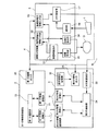
図1は、情報通信システムの具体的な第1実施形態を示す図である。 FIG. 1 is a diagram showing a specific first embodiment of an information communication system.
この図1に示す情報通信システム1は、第1の情報通信装置2と第2の情報通信装置3と通信網4と接続設定装置5を備えている。この接続設定装置5は、接続設定装置に対する具体的な第1実施形態に相当する。
The information communication system 1 shown in FIG. 1 includes a first
第1の情報通信装置2は、1つ以上の第1の物理接続口21と第1の通信部22と第1の情報出力口23とを備えたものである。この第1の物理接続口21は、情報通信に用いられる通信線Lが物理的に接続されるものである。第1の通信部22は、第1の物理接続口21に接続された通信線Lを介して他の情報通信装置との間の情報通信を行うものである。第1の情報出力口23は、第1の物理接続口21を特定する物理接続口情報を外部に出力するものである。
The first
第2の情報通信装置3は、1つ以上の第2の物理接続口31と論理接続口記憶部32と対応被登録部33と第2の通信部34と第2の情報出力口35とを備えたものである。第2の物理接続口31は、情報通信の通信線Lが物理的に接続されるものである。論理接続口記憶部32は、第1の物理接続口21の論理的な接続相手となる論理接続口を特定する論理接続口情報を記憶したものである。対応被登録部33は、論理接続口情報が特定する論理接続口と第1の物理接続口21との論理的対応を示す情報が登録されるものである。第2の通信部34は、対応被登録部33に論理接続口との論理的対応が登録されている第1の物理接続口21を通信相手として、第2の物理接続口31に接続された通信線Lを介して情報通信を行うものである。第2の情報出力口35は、論理接続口記憶部32に記憶されている論理接続口情報を外部に出力するものである。
The second
第1の情報出力口23、第2の情報出力口35、および対応被登録部33は通信網4に接続されている。
The first
接続設定装置5は、装置被登録部51と物理接続口情報入手部52と論理接続口情報入手部53と接続口表示部54と装置表示部55と選択部56と対応登録部57とを備えたものである。
The
装置被登録部51は、第1の情報通信装置2を特定する第1装置情報と、第2の情報通信装置3を特定する第2装置情報とのそれぞれが登録されるものである。
The
物理接続口情報入手部52は、第1の物理接続口21を特定する物理接続口情報を、通信網4を介して入手するものである。この物理接続口情報は、第1の情報通信装置2の第1の情報出力口23から出力される情報である。また、物理接続口情報入手部52は、この物理接続口情報を、装置被登録部51に登録された第1装置情報で特定される第1の情報通信装置2の第1の情報出力口23から入手する。
The physical connection port
論理接続口情報入手部53は、通信網4を介して、第1の物理接続口21の論理的接続先の候補となる論理接続口を示す論理接続口情報を入手するものである。この論理接続口情報は、第2の情報通信装置3の第2の情報出力口35から出力される情報である。また、論理接続口情報入手部53は、この論理接続口情報を、装置被登録部51に登録された第2装置情報で特定される第2の情報通信装置3の第2の情報出力口35から入手する。
The logical connection port
接続口表示部54は、物理接続口情報入手部52から入手した物理接続口情報が特定した第1の物理接続口21を表す物理接続口マークを表示画面Dに表示するものである。
The connection
装置表示部55は、装置被登録部51に登録された第2装置情報で特定される第2の情報通信装置3を表す装置マークを表示画面Dに表示するものである。
The
選択部56は、表示画面D上に表示された物理接続口マークおよび装置マークに対する、入力機器Iを用いた選択操作を受けるものである。この選択操作によって、情報通信で互いに通信相手となる第1の物理接続口21および第2の情報通信装置3が選択される。
The
対応登録部57は、選択部56で選択された第2の情報通信装置3に、通信網4を介して、論理接続口と第1の物理接続口21との論理的対応を登録するものである。この論理的対応は、第2の情報通信装置3の対応被登録部33に登録される。また、第1の物理接続口との論理的対応が対応被登録部に登録される論理接続口は、選択部で選択された第2の情報通信装置3から論理接続口情報入手部53が入手した論理接続口情報によって特定されるものである。この論理的接続口との論理的対応が登録される第1の物理接続口21は、選択された第2の情報通信装置3の通信相手として選択部56で選択されたものである。
The
このような情報通信システム1によれば、接続設定に必要な情報のほとんどは接続設定装置5が収集してくる。このためユーザは、表示画面Dに表示された、アイコンに代表されるマークを選択操作によって選択することによって感覚的に接続口の接続関係を指定することができ、効率的かつ確実な接続設定が実現できる。
According to such an information communication system 1, most of the information necessary for connection setting is collected by the
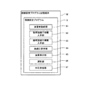
図2は、接続設定プログラムの具体的な第1実施形態を示す図である。 FIG. 2 is a diagram showing a specific first embodiment of the connection setting program.
図2に示す接続設定プログラム6は接続設定プログラム記憶媒体Mに記憶されている。この接続設定プログラム6は接続設定プログラム記憶媒体Mからコンピュータに取り込まれる。
The
この接続設定プログラム記憶媒体Mは、接続設定プログラムを記憶するものであれば何でも良い。この接続設定プログラム記憶媒体Mは、例えば、CDやDVDに代表される可搬型媒体であってもよく、ハードディスク装置に内蔵された磁気ディスクに代表される固定型媒体であってもよい。また、この接続設定プログラム記憶媒体Mは、USBメモリに代表される固体記憶素子であってもよい。 The connection setting program storage medium M may be anything as long as it stores a connection setting program. The connection setting program storage medium M may be, for example, a portable medium typified by a CD or a DVD, or a fixed medium typified by a magnetic disk built in a hard disk device. The connection setting program storage medium M may be a solid-state storage element represented by a USB memory.
また、接続設定プログラム6は、接続設定プログラム記憶媒体Mを介さずに、電気通信網を介して、他の装置からコンピュータに取り込まれるものであってもよい。
Further, the
接続設定プログラム6は、取り込まれたコンピュータ上で実行されることにより、そのコンピュータ上に、図1に示す接続設定装置5を構築する。
The
より具体的には、この図2に示す接続設定プログラム6は、装置被登録部61と物理接続口情報入手部62と論理接続口情報入手部63と接続口表示部64と装置表示部65と選択部66と対応登録部67とを備えている。そして、接続設定プログラム6に備えられている装置被登録部61と物理接続口情報入手部62は、それぞれ、図1に示す接続設定装置5の装置被登録部51と物理接続口情報入手部52を構築する。また、接続設定プログラム6に備えられている論理接続口情報入手部63と接続口表示部64は、それぞれ、図1に示す接続設定装置5の論理接続口情報入手部53と接続口表示部54を構築する。また、接続設定プログラム6に備えられている装置表示部65と選択部66と対応登録部67は、それぞれ、図1に示す接続設定装置5の装置表示部55と選択部56と対応登録部57を構築する。
More specifically, the
次に、情報通信システム、接続設定装置、および接続設定プログラムに対する具体的な第2実施形態について以下説明する。 Next, a specific second embodiment for the information communication system, the connection setting device, and the connection setting program will be described below.
この第2実施形態は、以下のような第1応用形態および第2応用形態それぞれに対する一例に相当する。 The second embodiment corresponds to an example for each of the following first application form and second application form.
この第1応用形態では、上記第2の情報通信装置は、接続済接続口確認部を備えている。この接続済接続口確認部は、上記第2の物理接続口に物理的に接続済の通信線を介して、その通信線が接続されている第1の物理接続口を特定する物理接続口情報を入手するものである。また、この第1応用形態では、上記第2の情報通信装置の上記第2の情報出力口が、上記接続済接続口確認部で入手された物理接続口情報も出力するものとなっている。さらにこの第1応用形態では、上記接続設定装置が、接続済情報入手部と接続確認部とを備えている。接続済情報入手部は、上記選択部で選択された第2の情報通信装置の第2の情報出力口から上記通信網を介して、第2の情報通信装置の接続済接続口確認部で入手された物理接続口情報を入手する。また、接続確認部は、上記選択部で選択された第1の物理接続口を特定する物理接続口情報が、上記接続済情報入手部で入手された物理接続口情報に含まれているか確認する。さらにまたこの第1応用形態では、上記接続設定装置の上記対応登録部は、物理接続が確認された場合に、その第1の物理接続口と論理接続口との論理的対応を登録するものとなっている。この物理接続の確認とは、上記選択部で選択された第1の物理接続口を特定する物理接続口情報が、上記接続済情報入手部で入手された物理接続口情報に含まれていることが上記接続確認部で確認されることである。 In the first application mode, the second information communication apparatus includes a connected connection port confirmation unit. The connected connection port confirmation unit has physical connection port information for identifying the first physical connection port to which the communication line is connected via the communication line that is physically connected to the second physical connection port. Is to obtain. Moreover, in this 1st application form, the said 2nd information output port of a said 2nd information communication apparatus outputs the physical connection port information acquired in the said connected connection port confirmation part. Furthermore, in the first application mode, the connection setting device includes a connected information acquisition unit and a connection confirmation unit. The connected information obtaining unit is obtained from the second information output port of the second information communication device selected by the selection unit through the communication network through the connected connection port confirmation unit of the second information communication device. Obtained physical connection port information. The connection confirmation unit confirms whether the physical connection port information that identifies the first physical connection port selected by the selection unit is included in the physical connection port information acquired by the connected information acquisition unit. . Furthermore, in the first application mode, the correspondence registration unit of the connection setting device registers the logical correspondence between the first physical connection port and the logical connection port when the physical connection is confirmed. It has become. The confirmation of the physical connection means that physical connection port information specifying the first physical connection port selected by the selection unit is included in the physical connection port information acquired by the connected information acquisition unit. Is confirmed by the connection confirmation unit.
このような第1応用形態によれば、対応登録部によって登録される論理的対応について、実際に物理的に通信可能であることが保証されることとなる。 According to such a first application mode, it is guaranteed that the logical correspondence registered by the correspondence registration unit is actually physically communicable.
また、第2応用形態は、第1の情報通信装置として、第2の情報通信装置を介して相互間で情報通信を行う複数種類の装置を備えている。また、この第2応用形態では、上記第2の情報通信装置が、上記複数種類の装置の相互間の情報通信における論理的な通信経路を構築するものとなっている。 Further, the second application form includes a plurality of types of devices that perform information communication between each other via the second information communication device as the first information communication device. In the second application mode, the second information communication device constructs a logical communication path in information communication between the plurality of types of devices.
このような第2応用形態によれば、複数種類の第1の情報通信装置が相互に通信経路で接続されたネットワークを効率的かつ確実に構築することができる。 According to such a second application mode, it is possible to efficiently and reliably construct a network in which a plurality of types of first information communication devices are connected to each other via communication paths.
図3は、情報通信システムの具体的な第2実施形態に相当するストレージ・エリア・ネットワーク(SAN:Storage Area Network)を示す図である。 FIG. 3 is a diagram showing a storage area network (SAN) corresponding to a specific second embodiment of the information communication system.
この図3に示すストレージ・エリア・ネットワーク100は、業務サーバ110とストレージ装置120と仮想化スイッチ130とを備えている。これら業務サーバ110とストレージ装置120と仮想化スイッチ130は互いにファイバーチャネル(FC)170で接続されている。このファイバーチャネル170は、物理的には一例として光ファイバーケーブルである。なお、この図3では図示の便宜上、業務サーバ110とストレージ装置120が1つずつ示されているが、ストレージ・エリア・ネットワーク100には業務サーバ110もストレージ装置120も複数備えられてもよい。
The
業務サーバ110は、図示を省略した他のコンピュータからのアクセスを受けて各種のサービスを提供するものである。そして、業務サーバ110は、そのサービスの提供に伴う多量の情報記録や情報提供をストレージ・エリア・ネットワーク100によって実現する。ストレージ装置120は、ストレージ・エリア・ネットワーク100における記憶領域を担う装置である。各ストレージ装置120によって提供される記憶領域が仮想化スイッチ130によって束ねられて1つの大きな情報記憶装置として機能する。
The
業務サーバ110は、ファイバーチャネル170の接続箇所となるホストバスアダプタ(HBA)111を複数備えている。また、ストレージ装置120は、ファイバーチャネル170の接続箇所となるチャネルアダプタ(CA)121を複数備えている。仮想化スイッチ130は、これらホストバスアダプタ111とチャネルアダプタ121とを互いに接続する接続経路の設定や切り替えを行うためのFCスイッチの一種である。
The
ストレージ装置120内では、1つ以上のチャネルアダプタ121がまとめられて1つのゾーン120aとして管理されている。このゾーン120aは論理的な存在である。ここでは図示が省略されているが、ストレージ装置120内ではこのゾーン120aとは別のゾーンも管理されている。また、ストレージ装置120は物理的な大容量の記憶領域を備えている。ストレージ装置120はその記憶領域に、論理的な存在である論理ボリューム120bを割り当てている。さらにストレージ装置120は、その論理ボリューム120bをゾーン120aに対応付けているとともに、別のゾーンには別の論理ボリュームを割り当てている。業務サーバ110などといった外部装置は、その論理ボリューム120bを指定することで記憶領域にアクセスする。しかし、別のゾーンの論理ボリュームを指定することが禁止されているため、ゾーン毎の排他的なアクセスが実現している。
In the
このストレージ・エリア・ネットワーク100には更に、運用管理クライアント150と運用管理サーバ160が備えられている。これら運用管理クライアント150と運用管理サーバ160は、業務サーバ110とストレージ装置120と仮想化スイッチ130に対してLAN(Local Area Network)140で接続されている。これら運用管理クライアント150と運用管理サーバ160は、ストレージ・エリア・ネットワーク100を管理するものである。
The
具体的には、運用管理クライアント150と運用管理サーバ160は、仮想化スイッチ130における接続経路の設定や切り替え、およびストレージ装置におけるゾーン120aや論理ボリューム120bの割り当てを管理している。これら運用管理クライアント150と運用管理サーバ160は所謂サーバクライアントシステムとなっている。すなわち、運用管理クライアント150からの指示に従って運用管理サーバ160が業務サーバ110とストレージ装置120と仮想化スイッチ130にアクセスする。また、運用管理サーバ160は、業務サーバ110、ストレージ装置120、および仮想化スイッチ130に対して定期的かつ自動的にアクセスすることで各種の情報を収集している。その結果、運用管理サーバ160には、業務サーバ110およびストレージ装置120におけるホストバスアダプタ111およびチャネルアダプタ121のWWPNが記憶されている。また、上記情報収集の結果、運用管理サーバ160には、ストレージ・エリア・ネットワーク100上での装置同士の接続関係を表した接続情報も記憶されている。
Specifically, the
業務サーバ110およびストレージ装置120のそれぞれが、第1の情報通信装置の一例に相当する。そして、業務サーバ110およびストレージ装置120は、上記第2応用形態における複数種類の第1の情報通信装置の一例に相当する。ホストバスアダプタ(HBA)111およびチャネルアダプタ(CA)121のそれぞれが、第1の物理接続口の一例に相当する。仮想化スイッチ130は、第2の情報通信装置の一例に相当すると共に、上記第2応用形態における第2の情報通信装置の一例にも相当する。LAN140と運用管理サーバ160との組み合わせが、通信網の一例に相当する。そして、運用管理サーバ160は、その通信網上での情報仲介を担った装置と言うことになる。ファイバーチャネル(FC)170が、通信線の一例に相当する。
Each of the
ここで、運用管理クライアント150のハードウェアとしては、本実施形態ではパーソナルコンピュータが用いられている。また、運用管理サーバ160のハードウェアとしては、本実施形態では汎用のサーバコンピュータが用いられている。
Here, as hardware of the
図4は、ストレージ・エリア・ネットワークが備えた各種装置の外観を示す図である。 FIG. 4 is a diagram showing the appearance of various devices provided in the storage area network.
この図4のパート(A)には業務サーバ110の外観が示されている。また、この図4のパート(B)には仮想化スイッチ130の外観が示され、パート(C)にはストレージ装置120の外観が示されている。業務サーバ110、ストレージ装置120、仮想化スイッチ130のいずれも箱状の外観を有した装置である。また、これらの装置はいずれも、ファイバーチャネルやLANといった通信線を介して外部装置と情報を遣り取りすることで機能を果たす装置である。
Part (A) of FIG. 4 shows the appearance of the
図5は、業務サーバの内部構造を示す図である。 FIG. 5 is a diagram illustrating the internal structure of the business server.
業務サーバ110には、上述したホストバスアダプタ111の他にも、通信部112とCPU(Center Processing Unit)113とフラッシュメモリ114とメモリ制御部115とLAN端子116が備えられている。また、通信部112には、情報通信部112aと接続確認部112bとしての機能が組み込まれている。但し、この図5に示した業務サーバ110の構成図には、ストレージ・エリア・ネットワーク100における接続経路の構築に必要な機能に限定した構成要素が示されている。業務サーバ110には、この図5に示された構成要素の他にも、業務サーバ110としてサービス提供機能を果たすための構成要素が備えられている。
In addition to the
通信部112は、業務サーバ110がホストバスアダプタ111を介して外部と情報を通信する機能を担っている。この通信部112に備えられた情報通信部112aは、CPU113によって処理される情報をホストバスアダプタ111および上述したファイバーチャネル170を介して外部装置(特にストレージ装置120)と通信するものである。フラッシュメモリ114には、ホストバスアダプタ111を一意に特定するためのWWPN(ワールドワイドポートネーム)が記憶されている。メモリ制御部115はフラッシュメモリ114に対する情報の読み書きを制御するものであるが、接続経路の構築では専らWWPNの読出しを担っている。LAN端子116はLANケーブルが接続される端子である。業務サーバ110はこのLAN端子116を介して本来のサービス提供を行うが、接続経路の構築ではこのLAN端子116は、専らホストバスアダプタ111のWWPNを出力するために用いられる。
The
通信部112に備えられた接続確認部112bは、ファイバーチャネル170を介してホストバスアダプタ111に接続された通信相手の装置に対し、ファイバーチャネル170経由でホストバスアダプタ111のWWPNを通知するものである。
The
通信部112のうちの特に情報通信部112aは、第1の通信部の一例に相当する。LAN端子116は、第1の情報出力口の一例に相当する。
In particular, the
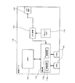
図6は、ストレージ装置の内部構造を示す図である。 FIG. 6 shows the internal structure of the storage apparatus.
ストレージ装置120は、上述したチャネルアダプタ121の他にも、コントロールモジュール(CM)122と通信部123と記憶媒体124と設定記憶部125と設定制御部126とLAN端子127とを備えている。
In addition to the
コントロールモジュール122はチャネルアダプタ121を制御するものである。記憶媒体124は、ストレージ装置が提供する記憶領域を物理的に担う媒体である。通信部123は、チャネルアダプタ121を介して外部装置と情報通信を行うものである。この通信部123が有する情報通信部123aは、外部装置が記憶媒体124にアクセスするときの通信を制御する。この情報通信部123aの制御によって、図3に示したゾーン120aや論理ボリューム120bが現実化する。
The
設定記憶部125のハードウェアとしては、本実施形態ではフラッシュメモリが用いられている。設定記憶部125には、チャネルアダプタ121を一意に特定するためのWWPN125aと、図3に示したゾーン120aや論理ボリューム120bの設定を含んだゾーン設定情報125bが記憶されている。設定制御部126は、設定記憶部125に対する情報の読み書きを制御するものである。通信部123が有する情報通信部123aは、設定制御部126を介して設定記憶部125からゾーン設定情報125bを入手する。そして、情報通信部123aは入手したゾーン設定情報125bを使うことで図3に示したゾーン120aや論理ボリューム120bを現実化する。このゾーン設定情報125bには、あるゾーン120aに属するチャネルアダプタ121のWWPNや、そのゾーン120aからアクセス可能な論理ボリューム120bの区分が含まれている。また、そのゾーン120aにチャネルアダプタ121を介してアクセス可能な接続相手のWWPNも含まれる。これらの情報のうち、接続相手のWWPNを設定する手順については後述するが、その他の情報については従前の手順で設定済であるという前提で説明する。
As the hardware of the setting
通信部123が有する接続確認部123bは、設定制御部126を介して設定記憶部125からチャネルアダプタ121のWWPN125aを入手する。
The
そして接続確認部123bは、ファイバーチャネル170を介してチャネルアダプタ121に物理的に接続された通信相手の装置(本実施形態では仮想化スイッチ)に対し、その入手したWWPN125aをファイバーチャネル170経由で通知する。
Then, the
LAN端子127はLANケーブルが接続される端子である。設定制御部126には、このLAN端子127経由で命令が入力される。この命令は、本実施形態では運用管理サーバ160から入力されるが、運用管理クライアント150からの入力も可能な命令である。設定制御部126は、このLAN端子127経由の命令に従って設定記憶部125に対してゾーン設定情報125bを登録する。また、このLAN端子127経由の別の命令に従って設定制御部126は、設定記憶部125に記憶されているWWPN125aをLAN端子127経由で出力する。
The
通信部123が有する情報通信部123aは、第1の通信部の一例に相当する。LAN端子127は、第1の情報出力口の一例に相当する。チャネルアダプタ121のWWPN125aが、物理接続口情報の一例に相当する。
The
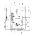
図7は、仮想化スイッチの内部構造を示す図である。 FIG. 7 is a diagram illustrating the internal structure of the virtualization switch.
仮想化スイッチ130は、チャネルポート(CP)131と通信部132と設定保存部133と設定制御部134とLAN端子135とを備えている。
The
チャネルポート131は、ファイバーチャネル170が接続される接続口である。通信部132は、チャネルポート131を介して業務サーバ110やストレージ装置120と情報通信を行うものである。通信部132が有する情報通信部132aはFCスイッチとしての機能を担うものである。即ち、情報通信部132aは業務サーバ110とストレージ装置120とを相互に接続する情報通信経路を構築する。
The
設定保存部133のハードウェアとしては、本実施形態ではフラッシュメモリが用いられている。設定保存部133には、物理接続情報133aとVT・VI情報133bとゾーニング設定情報133cとスイッチ設定情報133dが保存される。この物理接続情報133aは、チャネルポート131に接続されたファイバーチャネル170を介して接続された通信相手のWWPNである。またVT・VI情報133bは、仮想イニシエータ(VI)を表したWWPNと仮想ターゲット(VT)を表したWWPNである。この仮想イニシエータ(VI)は、ストレージ装置120のチャネルアダプタ121に対する論理的な通信相手となる。また、仮想ターゲット(VT)は、業務サーバ110のホストバスアダプタ111に対する論理的な通信相手となる。ゾーニング設定情報133cは、チャネルアダプタ121のWWPNと仮想イニシエータのWWPNとの組み合わせ、およびホストバスアダプタ111のWWPNと仮想ターゲットのWWPNとの組み合わせを表している。そして、そのような各組み合わせのことも本実施形態では「ゾーン」と称している。また、その組み合わせを表したゾーニング設定情報133cを設定保存部133に保存することを本実施形態では「ゾーニング設定」と称している。スイッチ設定情報133dは、仮想イニシエータと仮想ターゲットとの論理的な接続関係を表している。
As the hardware of the setting
設定制御部134は、設定保存部133に対する情報の読み書きを制御するものである。通信部132が有する情報通信部132aは、設定制御部134を介してゾーニング設定情報133cとスイッチ設定情報133dを入手する。そして情報通信部132aは、その入手したゾーニング設定情報133cとスイッチ設定情報133dが表す通信相手との情報通信を行う。このように情報通信部132aが情報通信を行うことで、図3に示すストレージ・エリア・ネットワーク100における接続構造が構築される。
The setting
通信部132が有する接続確認部132bは、チャネルポート131に接続されたファイバーチャネル170を介して業務サーバ110やストレージ装置120の接続確認部112b,123bからWWPNを入手する。そして接続確認部132bは、その入手したWWPNを設定制御部134経由で設定保存部133に物理接続情報133aとして保存する。
The
LAN端子135はLANケーブルが接続される端子である。このLAN端子135経由の命令に従って設定制御部134は、設定保存部133に対して、仮想ターゲットのWWPN、ゾーニング設定情報133c、スイッチ設定情報133dを保存する。
The
チャネルポート131が、第2の物理接続口の一例に相当する。情報通信部132aが、上記基本形態における第2の通信部の一例に相当する。接続確認部132bが、接続済接続口確認部の一例に相当する。設定保存部133と設定制御部134の組み合わせは、論理接続口記憶部の一例であると共に、対応被登録部の一例でもある。VT・VI情報133bが、論理接続口情報の一例に相当する。ゾーニング設定133cが、「論理的対応」の一例に相当する。LAN端子135が、第2の情報出力口の一例に相当するとともに、上記第1応用形態における第2の情報出力口の一例にも相当する。
The
図8は、運用管理クライアントの内部構造を示す図である。 FIG. 8 shows the internal structure of the operation management client.
上述したようにこの運用管理クライアント150のハードウェアとしては、本実施形態ではパーソナルコンピュータが用いられている。この運用管理クライアント150は、ハードウェア要素として、CPU154やLAN通信器155やメモリ156を内蔵した本体151と、ディスプレイ152と、キーボードやマウス等の入力機器153とを備えている。LAN通信器155は、LANケーブルが接続されることでLAN140に接続されるものである。メモリ156は、CPU154が情報処理に用いる処理変数などが記憶されるものである。
As described above, a personal computer is used as the hardware of the
CPU154は、装置構成設定部1541とGUI(Graphical User Interface)制御部1542として機能する。また、このCPU154は、サーバ・ストレージ情報アクセス部1543と仮想化スイッチ情報アクセス部1544とゾーニング設定部1545としても機能する。
The
なお、運用管理クライアント150のハードウェアおよびソフトウェアについては、この図8に示す要素以外にも、ストレージ・エリア・ネットワーク100の管理に必要な種々の要素が備えられている。しかし、この図8では、運用管理クライアント150が有する各種の機能のうち、ストレージ・エリア・ネットワーク100における装置相互の接続経路を設定する接続設定装置としての機能に着目して要素が図示されている。
Note that the hardware and software of the
装置構成設定部1541には、ストレージ・エリア・ネットワーク100に備えられた業務サーバ110、ストレージ装置120、仮想化スイッチ130といった各装置が入力機器153によって登録される。具体的には、各装置に対してLAN140経由でアクセスするためのIPアドレスが、各装置の種類と対応付けられて登録される。登録されたIPアドレスと装置種類との組み合わせは、装置構成設定部1541によってメモリ156に格納される。以後、運用管理クライアント150では、このIPアドレスによって各装置が特定される。
In the device
GUI制御部1542は、ストレージ・エリア・ネットワーク100における装置同士の接続経路をユーザが設定するためのGUIを、ディスプレイ152および入力機器153を制御することで構築するものである。GUI制御部1542の具体的な動作については後でフローチャートを参照して詳細に説明する。
The
サーバ・ストレージ情報アクセス部1543は、業務サーバ110およびストレージ装置120のLAN端子116,127から出力されるWWPNを、LAN通信器155およびLAN140を介して取得するものである。具体的には、サーバ・ストレージ情報アクセス部1543は、LAN端子116,127から出力されて運用管理サーバ160に収集されているWWPNで特定されるアクセス先にLAN140を介してアクセスする。このアクセスに際してサーバ・ストレージ情報アクセス部1543は、上述したIPアドレスで装置を特定し、その特定した装置から運用管理サーバ160が収集したWWPNを取得する。取得されたWWPNは、その特定された装置のIPアドレスに対応付けられてメモリ156に格納される。以後、運用管理クライアント150では、このWWPNによって各装置のホストバスアダプタ111およびチャネルアダプタ121が特定される。
The server / storage
仮想化スイッチ情報アクセス部1544は、仮想化スイッチ130のLAN端子135から出力される各種情報を、LAN通信器155およびLAN140を介して取得するものである。具体的には、仮想化スイッチ情報アクセス部1544は、LAN端子135から出力されて運用管理サーバ160に集約されている情報にLAN140を介してアクセスする。このアクセスに際して仮想化スイッチ情報アクセス部1544は、上述したIPアドレスで仮想化スイッチ130を特定し、その特定した仮想化スイッチ130から運用管理サーバ160が収集した情報を取得する。取得された情報は、その特定された仮想化スイッチ130のIPアドレスに対応付けられてメモリ156に格納される。
The virtualization switch
ゾーニング設定部1545は、仮想化スイッチ130の設定保存部133に対してLAN通信器155およびLAN140を介してゾーニング設定情報133cを登録するものである。具体的には、ゾーニング設定部1545は、設定登録の指示を運用管理サーバ160に出すことによって、ゾーニング設定情報133cを登録するための各種の命令を運用管理サーバ160から仮想化スイッチ130へと出力させる。
The
ディスプレイ152は、表示画面の一例に相当する。装置構成設定部1541は、装置被登録部の一例に相当する。GUI制御部1542は、接続口表示部と装置表示部と選択部とを兼ねた一例に相当する。サーバ・ストレージ情報アクセス部1543は、物理接続口情報入手部の一例に相当する。仮想化スイッチ情報アクセス部1544は、論理接続口情報入手部の一例に相当するとともに、上記第1応用形態における接続済情報入手部および接続確認部を兼ねた一例にも相当する。ゾーニング設定部1545は、対応登録部の一例に相当する。
The
ここで、CPU154に備えられた、図8に示すソフトウェア要素は、運用クライアント150のハードウェアであるコンピュータにゾーニング設定プログラムが組みこまれて実行されることで構築されたものである。
Here, the software elements shown in FIG. 8 provided in the
図9は、ゾーニング設定プログラムを示す図である。 FIG. 9 is a diagram showing a zoning setting program.
この図9に示すゾーニング設定プログラム200は、接続設定プログラムに対する具体的な第2実施形態に相当する。
The
このゾーニング設定プログラム200はCDROM201に記憶されている。このゾーニング設定プログラム200を記憶したCDROM201がコンピュータに装填されると、ゾーニング設定プログラム200はそのコンピュータによって読み出される。そして、その読み出されたゾーニング設定プログラム200はコンピュータ内に組み込まれる。そのように組み込まれたゾーニング設定プログラム200がそのコンピュータ上で実行されることにより、図8に示すCPU154に備えられた各ソフトウェア要素が構築される。
The
尚、接続設定プログラムの実施形態を記憶する記憶媒体としては、CDROMに代表されるCD型媒体以外にも、DVDであってもよく、フレキシブルディスク(FD)であってもよい。また、そのような記憶媒体としては、ハードディスク装置に内蔵された磁気ディスクであってもよく、USBメモリに代表される固体記憶素子であっても良い。また、接続設定プログラムの実施形態としては、コンピュータに接続された他の装置から接続設定プログラムを、電気通信網を介してコンピュータに供給する形態もあり得る。 The storage medium for storing the embodiment of the connection setting program may be a DVD or a flexible disk (FD) in addition to a CD-type medium represented by CDROM. Such a storage medium may be a magnetic disk built in a hard disk device or a solid-state storage element represented by a USB memory. In addition, as an embodiment of the connection setting program, there may be a form in which the connection setting program is supplied to the computer via another telecommunication network from another device connected to the computer.
ゾーニング設定プログラム200は、装置構成設定部210とGUI制御部220とサーバ・ストレージ情報アクセス部230と仮想化スイッチ情報アクセス部240とゾーニング設定部250を備えている。この図9に示すゾーニング設定プログラム200の装置構成設定部210は、図8に示す運用管理クライアント150の装置構成設定部1541を構築する。また、ゾーニング設定プログラム200のGUI制御部220およびサーバ・ストレージ情報アクセス部230は、それぞれ、運用管理クライアント150のGUI制御部1542およびサーバ・ストレージ情報アクセス部1543を構築する。そして、ゾーニング設定プログラム200の仮想化スイッチ情報アクセス部240は、運用管理クライアント150の仮想化スイッチ情報アクセス部1544を構築する。更に、ゾーニング設定プログラム200のゾーニング設定部250は、運用管理クライアント150のゾーニング設定部1545を構築する。
The
このようなゾーニング設定プログラム200によって構築されるソフトウェア要素の動作を中心として、図8に示す運用管理クライアント150の動作について、以下、フローチャートを参照しながら説明する。以下のフローチャートの説明に際しては、図3〜図8に示された要素を、特に図番を断らずに引用する場合がある。
The operation of the
図10は、運用管理クライアントのメイン動作を表すフローチャートである。但し、図10のフローチャートは、運用管理クライアント150を操作するユーザの手順に着目したフローチャートとなっている。また、ここでは、ストレージ・エリア・ネットワーク100が有する装置のうち、業務サーバ110と仮想化スイッチ130との接続設定に着目した動作説明となっている。
FIG. 10 is a flowchart showing the main operation of the operation management client. However, the flowchart of FIG. 10 is a flowchart focusing on the procedure of the user who operates the
まずユーザは、運用管理クライアント150の入力機器153を操作して装置構成設定部1541に業務サーバ110を登録する(ステップS101)。上述したようにこの登録では、登録される業務サーバ110のIPアドレスが「業務サーバ」という装置種類と組み合わされた情報が装置構成設定部1541に入力される。次にユーザは、運用管理クライアント150の入力機器153を操作して装置構成設定部1541に仮想化スイッチ130を登録する(ステップS102)。この仮想化スイッチ130の登録でも、登録される仮想化スイッチ130のIPアドレスが「仮想化スイッチ」という装置種類と組み合わされた情報が装置構成設定部1541に入力される。更にユーザは、運用管理クライアント150の入力機器153を操作して装置構成設定部1541にストレージ装置120を登録する(ステップS103)。このストレージ装置120の登録でも、登録されるストレージ装置120のIPアドレスが「ストレージ装置」という装置種類と組み合わされた情報が装置構成設定部1541に入力される。このように、ステップS101〜S103でIPアドレスと装置種類との組み合わせ情報が入力された装置構成設定部1541は、メモリ156にその組み合わせ情報を格納する。これらの装置の登録に際しては、運用管理クライアント150のディスプレイ152には装置登録用の登録画面が表示される。そして、ユーザは、その登録画面に対する情報入力を入力機器153の操作で行う。また、ステップS101〜S103の順番はユーザの操作順で決まるものであるので、この図10に示す順番である必要はない。ステップS101〜S103での装置の登録が終了すると、ユーザは、その登録画面に用意されている終了ボタンをクリックする。すると、運用管理クライアント150は、ディスプレイ152上に接続設定用のGUI画面を表示する表示処理を実行する(ステップS104)。
First, the user operates the
図11は、GUI画面の表示処理を表すフローチャートである。 FIG. 11 is a flowchart showing a GUI screen display process.
この表示処理が開始されると、まず、運用管理クライアント150のサーバ・ストレージ情報アクセス部1543が、上記で登録された業務サーバおよびストレージ装置のWWPNを運用管理サーバ160から取得する(ステップS111)。サーバ・ストレージ情報アクセス部1543は、その取得したWWPNを、上述した組み合わせ情報に対応付けてメモリ156に格納する。次に、仮想化スイッチ情報アクセス部1544が運用管理サーバ160から、上記で登録された業務サーバ、ストレージ装置、および仮想化スイッチの接続情報を取得する(ステップS112)。そして仮想化スイッチ情報アクセス部1544は、この接続情報をメモリ156に格納する。
When this display processing is started, first, the server / storage
このように運用管理サーバ160から情報が取得されると、GUI制御部1542がディスプレイ152上に、上記で登録された業務サーバ、ストレージ装置、および仮想化スイッチそれぞれのアイコンを表示する(ステップS113)。より具体的には、GUI制御部1542は、メモリ156に格納されている組み合わせ情報で各装置の種類を確認する。そして、装置の種類毎に用意されているアイコンを各装置に割り当て、その割り当てたアイコンをディスプレイ152上に表示する。
When information is acquired from the
その後GUI制御部1542は、このように表示したアイコンの相互間に、上記ステップS112で取得された接続情報が表している接続関係を表したラインを表示する(ステップS114)。
Thereafter, the
図12は、接続設定用のGUI画面を示す図である。 FIG. 12 is a diagram showing a connection setting GUI screen.
図12に示すGUI画面300には、業務サーバを表した業務サーバアイコン310と、ストレージ装置を表したストレージ装置アイコン320と、仮想化スイッチを表した仮想化スイッチアイコン330が表示されている。また、業務サーバアイコン310には、業務サーバが備えたホストバスアダプタを表したHBAアイコン311も表示されている。フローチャートでは省略されているが、このHBAアイコン311は、業務サーバアイコン310がダブルクリックされたときに表示される。また、このHBAアイコン311は、図11のステップS111で取得されたWWPNによって特定される各ホストバスアダプタについてGUI制御部1542が表示するものである。図示は省略するが、ストレージ装置アイコン320がダブルクリックされたときにも同様に、ストレージ装置が備えたチャネルアダプタを表したCAアイコンが表示される。
The
この図に示すGUI画面300には、アイコン間に、物理的な接続を表す実線のライン340と、論理的な接続を表す幅広のライン350も表示されている。
On the
これらのライン340,350のうち実線のライン340は、仮想化スイッチ130の設定保存部133に記憶されていた物理接続情報133aに基づいて表示される。また、幅広のライン350は、仮想化スイッチ130の設定保存部133に記憶されていたゾーニング設定情報133cに基づいて表示される。
Of these
これらのライン340,350の表示に用いられる物理接続情報133aおよびゾーニング設定情報133cは、運用管理サーバ160による定期的なアクセス時に、仮想化スイッチ130の設定保存部133から運用管理サーバ160に取得される。これらの上方は、その後、図11のステップS112で仮想化スイッチ情報アクセス部1544によって取得される。但し、このようにGUI画面300に表示されるラインは、GUI画面300が最初に表示されたときに取得された情報に基づいて表示されるものであるので、GUI画面300の表示後の情報変化は反映されていない。そのため、接続状態に関しては、後で最新の情報が改めて取得されることとなる。
The
仮想化スイッチアイコン330が、装置マークの一例に相当する。HBAアイコン311およびCAアイコンが、物理接続口マークの一例に相当する。
The
ユーザは、業務サーバと仮想化スイッチとの接続設定を行う場合には、図12のようなGUI画面300上で、HBAアイコン311から仮想化スイッチアイコン330にドラッグ&ドロップを行う(図10のステップS105)。運用管理クライアント150のGUI制御部1542は、ドラッグ&ドロップの操作を検知することで、接続対象として選択されたホストバスアダプタと仮想化スイッチを認識する。そして、GUI制御部1542は、その認識したホストバスアダプタと仮想化スイッチを表す選択情報を仮想化スイッチ情報アクセス部1544とゾーニング設定部1545に伝達する。その後、運用管理クライアント150では、サーバと仮想化スイッチ間のゾーニング設定処理が実行される(図10のステップS106)。
When setting the connection between the business server and the virtualization switch, the user drags and drops from the
図13は、サーバと仮想化スイッチ間のゾーニング設定処理を表すフローチャートである。 FIG. 13 is a flowchart showing a zoning setting process between the server and the virtualization switch.
この図13に示す処理では、まずステップS201で、運用管理クライアント150の仮想化スイッチ情報アクセス部1544が物理接続情報を入手する。この物理接続情報は、仮想化スイッチ情報アクセス部1544が、GUI制御部1542から伝達された選択情報が表した仮想化スイッチについて運用管理サーバ160にアクセスすることで入手される。
In the processing shown in FIG. 13, first, in step S201, the virtualization switch
ここで、運用管理サーバ160に記憶されている物理接続情報の詳細について説明する。
Here, details of the physical connection information stored in the
図14は、運用管理サーバに記憶されている物理接続情報を示す図である。 FIG. 14 is a diagram showing physical connection information stored in the operation management server.
運用管理サーバ160には、LAN140で接続された各仮想化スイッチ130の設定保存部133から収集された物理接続情報400が、仮想化スイッチ毎にまとめられて記憶されている。この物理接続情報400には、HBAの物理接続情報410とTV情報420とCAの物理接続情報430とTI情報440が含まれている。
In the
HBAの物理接続情報410とCAの物理接続情報430は、仮想化スイッチ130の設定保存部133に保存されていた物理接続情報133aに相当するものである。
The HBA
HBAの物理接続情報410には、具体的には、仮想化スイッチ130の接続確認部132bによって確認された物理的な接続先の各ホストバスアダプタ111のWWPNが列記されている。同様に、CAの物理接続情報430には、仮想化スイッチ130の接続確認部132bによって確認された物理的な接続先のチャネルアダプタ121のWWPNが列記されている。
Specifically, the
VT情報420とVI情報440は、仮想化スイッチ130の設定保存部133に保存されていたVT・VI情報133bに相当するものである。VT情報420には、ホストバスアダプタ111の論理的な接続相手となる論理的な接続口を表すWWPNが列記されている。ホストバスアダプタ111に接続されているファイバーチャネル170は、物理的には仮想化スイッチ130のチャネルポート131に接続されるのであるが、このチャネルポート131にはWWPNは付与されていない。仮想化スイッチ130は、ファイバーチャネル170が物理的にどのチャネルポート131に接続されているかに関わらず通信部132の情報通信部132aによって接続先のWWPNを切り換えることができる。そして、ホストバスアダプタ111の接続相手としては、VT情報420として事前にユーザが設定しているWWPNのなかから選択されたものに切替可能となっている。一方、VI情報440には、チャネルアダプタ121の論理的な接続相手となる論理的な接続口を表すWWPNが列記されている。このVI情報440に列記されているWWPNは、仮想化スイッチ130の出荷時には既に登録されているものであってユーザによる変更や追加はできない。そして、チャネルアダプタ121の接続相手は、このVI情報440に列記されているWWPNの全て(この図14では2つ)となる。
The
このような物理接続情報400が図13のステップS201で仮想化スイッチ情報アクセス部1544によって取得されると、仮想化スイッチ情報アクセス部1544はその物理接続情報400をメモリ156に格納する。そして、ステップS201ではさらに仮想化スイッチ情報アクセス部1544によって、その物理接続情報400に含まれているHBAの物理接続情報410に列挙されているWWPNに対してWWPNの検索が行われる。この検索で探されるWWPNは、GUI制御部1542から伝達された選択情報が表したホストバスアダプタのWWPNである。
When such
次にステップS202では、仮想化スイッチ情報アクセス部1544によって、そのホストバスアダプタのWWPNがHBAの物理接続情報410中に存在するか否かが判定される。そして、ホストバスアダプタのWWPNが存在しないと判定された場合には、GUIでユーザが接続対象として選択したホストバスアダプタと仮想化スイッチとが物理的には未接続であるということになる。そのため、運用管理クライアント150は、その選択されたホストバスアダプタと仮想化スイッチとが物理的には未接続である旨をユーザに通知する(ステップS203)。この通知は、例えばメッセージをディスプレイ152に表示するなどといった手段で行われる。
In step S202, the virtualization switch
一方、ステップS202で、選択されたホストバスアダプタのWWPNがHBAの物理接続情報410中に存在すると判定された場合には、ユーザが接続対象として選択したホストバスアダプタと仮想化スイッチとが物理的にも接続されていることとなる。
On the other hand, if it is determined in step S202 that the WWPN of the selected host bus adapter exists in the
この場合、ステップS204では、物理接続情報400のVT情報420に列挙されているWWPNから1つのWWPNを選択させる選択ダイアログがゾーニング設定部1545によってディスプレイ152上に表示される。ユーザは入力機器153を介してその選択ダイアログを操作することで、WWPNを選択する。この選択されたWWPNが、接続対象としての仮想ターゲットのWWPNをあらわす。
In this case, in step S204, a selection dialog for selecting one WWPN from the WWPNs listed in the
このように、GUIで選択されたホストバスアダプタのWWPNと、ステップS204で選択された仮想ターゲットのWWPNとが互いに接続対象となる。 As described above, the WWPN of the host bus adapter selected by the GUI and the WWPN of the virtual target selected in step S204 are mutually connected.
このようにして、互いに接続対象となるWWPNの組み合わせが確定すると、ゾーニング設定部1545は運用管理サーバ160に対してその組み合わせでのゾーニング設定を指示する(ステップS205)。そして、ステップS206では、運用管理サーバ160が仮想化スイッチ130に対してLAN140経由でコマンドを入力する。その結果、仮想化スイッチ130の設定保存部133内には、その組み合わせに相当するゾーニング設定情報133cが保存されることとなる。より具体的には、運用管理サーバ160は、まずLAN140経由で仮想化スイッチ130にログインする。次に、運用管理サーバ160はzonecreateコマンドを発行することで、その組み合わせ中のホストバスアダプタのWWPNを有するゾーンを作成する。そして、運用管理サーバ160は、zoneaddコマンドを発行することでそのゾーンに、組み合わせ中の仮想ターゲットのWWPNを追加する。最後に、運用管理サーバ160はそのゾーンを表したゾーニング設定情報133cを、cfgaddコマンドを発行することで仮想化スイッチ130の設定保存部133内に保存させる。
In this way, when the combination of WWPNs to be connected to each other is determined, the
運用管理クライアント150等における以上説明した動作により、業務サーバ110のホストバスアダプタ111と、仮想化スイッチ130の仮想ターゲットとの間の論理的な接続が設定される。
The logical connection between the
この接続の設定に際し、ユーザは、ストレージ・エリア・ネットワーク100が有する装置のうち接続を望む装置のIPアドレスを知らべること以外には、特には情報の調査が不要となるので接続設定が効率的に実行される。また、ユーザによるGUIの操作によって所望の装置同士の接続が確実に設定されることとなる。
When setting up this connection, the user can know the IP address of the device that the
さらに、本実施形態では、物理的な接続が確認された上で論理的接続が設定されるので、論理的接続が確実に実現されることとなる。 Furthermore, in this embodiment, the logical connection is set after the physical connection is confirmed, so that the logical connection is reliably realized.
以上では、ストレージ・エリア・ネットワーク100が有する装置のうち、業務サーバ110と仮想化スイッチ130との接続設定に着目した動作説明を行ったが、以下では、仮想化スイッチ130とストレージ装置120との接続設定に着目した動作説明を行う。
In the above, the operation description focusing on the connection setting between the
図15は、運用管理クライアントのメイン動作を表す、仮想化スイッチとストレージ装置との接続設定に着目したフローチャートである。 FIG. 15 is a flowchart showing the main operation of the operation management client, focusing on the connection setting between the virtualization switch and the storage apparatus.
この図15には6つのステップS301〜S306が示されているが、これらのステップのうち前半の4つのステップS301〜S304については、図10に示すステップS101〜S104と全く同じ動作であるので重複説明は省略する。 FIG. 15 shows six steps S301 to S306. Of these steps, the first four steps S301 to S304 are the same as steps S101 to S104 shown in FIG. Description is omitted.
ユーザは、仮想化スイッチとストレージ装置との接続設定を行う場合には、図12のようなGUI画面300上で、仮想化スイッチアイコン330からストレージのCAアイコン(図示は省略)にドラッグ&ドロップを行う(ステップS305)。運用管理クライアント150のGUI制御部1542は、ドラッグ&ドロップの操作を検知することで、接続対象として選択されたチャネルアダプタと仮想化スイッチを認識する。そして、GUI制御部1542は、その認識したチャネルアダプタと仮想化スイッチを表した選択情報を仮想化スイッチ情報アクセス部1544とゾーニング設定部1545に伝達する。その後、運用管理クライアント150では、仮想化スイッチとストレージ装置間のゾーニング設定処理が実行される(ステップS306)。
When setting the connection between the virtualization switch and the storage device, the user drags and drops from the
図16は、仮想化スイッチとストレージ装置間のゾーニング設定処理を表すフローチャートである。 FIG. 16 is a flowchart showing a zoning setting process between the virtualization switch and the storage apparatus.
この図16に示す処理でも、まずステップS401で、運用管理クライアント150の仮想化スイッチ情報アクセス部1544が物理接続情報を入手する。この物理接続情報は、仮想化スイッチ情報アクセス部1544が、GUI制御部1542から伝達された選択情報が表した仮想化スイッチについて運用管理サーバ160にアクセスすることで入手される。
Also in the processing shown in FIG. 16, first, in step S401, the virtualization switch
そして取得された物理接続情報400は仮想化スイッチ情報アクセス部1544によってメモリ156に格納される。さらにステップS401では、仮想化スイッチ情報アクセス部1544によって、その物理接続情報400に含まれているCAの物理接続情報430に列挙されているWWPNに対してWWPNの検索が行われる。この検索で探されるWWPNは、GUI制御部1542から伝達された選択情報が表したチャネルアダプタのWWPNである。
The acquired
この検索の結果、そのチャネルアダプタのWWPNが存在しなかった場合には、GUIでユーザが接続対象として選択したチャネルアダプタと仮想化スイッチとが物理的には未接続であるということになる。そのため、運用管理クライアント150は、その選択されたチャネルアダプタと仮想化スイッチとが物理的には未接続である旨をユーザに通知する(ステップS402)。この通知は、例えばメッセージをディスプレイ152に表示するなどといった手段で行われる。
As a result of this search, if the WWPN of the channel adapter does not exist, the channel adapter selected by the user as a connection target on the GUI and the virtualization switch are physically unconnected. Therefore, the
一方、ステップS401の検索の結果、選択されたチャネルアダプタのWWPNがCAの物理接続情報430中に存在していた場合には、ユーザが接続対象として選択したチャネルアダプタと仮想化スイッチとが物理的にも接続されていることとなる。そして、仮想化スイッチとストレージ装置間のゾーニング設定の場合には、この物理的接続の確認により、自動的に、互いに接続対象となるWWPNの組み合わせが確定する。即ち、物理接続情報400のVI情報440に列挙されているWWPNの各々と、ユーザが接続対象として選択したチャネルアダプタのWWPNとが互いに接続対象となる。
On the other hand, if the WWPN of the selected channel adapter exists in the CA
選択されたチャネルアダプタのWWPNがCAの物理接続情報430中に存在していた場合には、ゾーニング設定部1545は運用管理サーバ160に対してその組み合わせでのゾーニング設定を指示する(ステップS403)。運用管理サーバ160は、仮想化スイッチ130に対してLAN140経由でコマンドを入力することで、設定保存部133内に、その組み合わせに相当するゾーニング設定情報133cを保存する(ステップS404)。より具体的には、運用管理サーバ160は、まずLAN140経由で仮想化スイッチ130にログインする。次に、運用管理サーバ160はzonecreateコマンドで、その組み合わせ中の各仮想イニシエータの各WWPNを有するゾーンを作成する。そして、運用管理サーバ160は、zoneaddコマンドでそのゾーンに、組み合わせ中のチャネルアダプタのWWPNを追加する。最後に、運用管理サーバ160はそのゾーンを表したゾーニング設定情報133cをcfgaddコマンドで仮想化スイッチ130の設定保存部133内に保存させる。
If the WWPN of the selected channel adapter exists in the CA
このようにゾーニング設定情報133cを設定保存部133内に保存させた運用管理サーバ160は、次に、接続対象の組み合わせ中のWWPNで特定されるチャネルアダプタを有するストレージ装置120にLAN140経由でログインする。そして、運用管理サーバ160は、ストレージ装置120の設定制御部126に、上記組み合わせに相当するゾーニング設定を指示する(ステップS405)。このような指示を受けた設定制御部126は、ゾーン設定情報125bを確認することで、上記組み合わせに含まれたチャネルアダプタ121のWWPNが属しているゾーン120aを認識する。そして、設定制御部126は、そのゾーン120aにアクセス可能な接続相手のWWPNとして、上記組み合わせ中の各仮想イニシエータの各WWPNを、ゾーン設定情報125bに追加設定する(ステップS406)。
The
運用管理クライアント150等における以上説明した動作により、仮想化スイッチ130の仮想イニシエータと、ストレージ装置120のチャネルアダプタ121の間の接続が設定される。この接続の設定に際しても、ユーザは、ストレージ・エリア・ネットワーク100が有する装置のうち接続を望む装置のIPアドレスを知らべること以外には、特には情報の調査が不要となるので接続設定が効率的に実行される。また、ユーザによるGUIの操作によって所望の装置同士の接続が確実に設定されることとなる。
With the operation described above in the
ストレージ・エリア・ネットワーク100、業務サーバ110、ホストバスアダプタ111、ストレージ装置120、チャネルアダプタ121、ゾーン120a、論理ボリューム120b、仮想化スイッチ130、LAN(Local Area Network)LAN140、運用管理クライアント150、運用管理サーバ160、ファイバーチャネル170
ホストバスアダプタ111、通信部112、情報通信部112a、接続確認部112b、CPU(Center Processing Unit)113、フラッシュメモリ114、メモリ制御部115、LAN端子116
チャネルアダプタ121、コントロールモジュール122、通信部123、情報通信部123a、接続確認部123b、記憶媒体124、設定記憶部125、CAのWWPN125a、ゾーン設定情報125b、設定制御部126、LAN端子127
チャネルポート131、通信部132、情報通信部132a、接続確認部132b、設定保存部133、物理接続情報133a、VT・VI情報133b、ゾーニング設定情報133c、スイッチ設定情報133d、設定制御部134、LAN端子135
本体151、ディスプレイ152、入力機器153、CPU154、LAN通信器155、メモリ156、装置構成設定部1541、GUI(Graphical User Interface)GUI制御部1542、サーバ・ストレージ情報アクセス部1543、仮想化スイッチ情報アクセス部1544、ゾーニング設定部1545
CDROM201、ゾーニング設定プログラム200、装置構成設定部210、GUI制御部220、サーバ・ストレージ情報アクセス部230、仮想化スイッチ情報アクセス部240、ゾーニング設定部250
物理接続情報400、HBAの物理接続情報410、VT情報420、CAの物理接続情報430、VI情報440
Claims (5)
前記第1の物理接続口を介して情報通信を行う第1の通信部と、
前記第1の物理接続口を特定する物理接続口情報を出力する第1の情報出力口とを備えた第1の情報通信装置;
情報通信の通信線が物理的に接続される第2の物理接続口と、
前記第1の物理接続口に対する論理的な接続先となる論理接続口を特定する論理接続口情報を記憶した論理接続口記憶部と、
前記論理接続口情報が特定する論理接続口と前記第1の物理接続口との論理的対応が登録される対応被登録部と、
前記対応被登録部に、論理接続口情報が特定する論理接続口との論理的対応が登録されている第1の物理接続口に対して前記第2の物理接続口を介して通信を行う第2の通信部と、
前記論理接続口記憶部に記憶されている論理接続口情報を出力する第2の情報出力口とを備えた第2の情報通信装置;
前記第1の情報通信装置を特定する第1装置情報と、前記第2の情報通信装置を特定する第2装置情報とが登録される装置被登録部と、
前記装置被登録部に登録された第1装置情報で特定される第1の情報通信装置の第1の情報出力口から前記物理接続口情報を入手する物理接続口情報入手部と、
前記装置被登録部に登録された第2装置情報で特定される第2の情報通信装置の第2の情報出力口から前記論理接続口情報を入手する論理接続口情報入手部と、
前記物理接続口情報によって特定される第1の物理接続口を表す物理接続口マークを表示画面に表示する接続口表示部と、
前記装置被登録部に登録された第2装置情報によって特定される第2の情報通信装置を表す装置マークを前記表示画面に表示する装置表示部と、
前記表示画面上に表示された物理接続口マークおよび装置マークに対する選択操作によって、情報通信で互いに通信相手となる第1の物理接続口および第2の情報通信装置が選択される選択部と、
前記選択部で選択された第2の情報通信装置の対応被登録部に、前記論理接続口情報入手部が入手した論理接続口情報によって特定される論理接続口と、前記選択部で選択された第1の物理接続口との論理的対応を登録する対応登録部とを備えた接続設定装置;
を備えたことを特徴とする情報通信システム。 A first physical connection port to which a communication line is physically connected;
A first communication unit that performs information communication via the first physical connection port;
A first information communication device comprising: a first information output port that outputs physical connection port information that identifies the first physical connection port;
A second physical connection port to which a communication line for information communication is physically connected;
A logical connection port storage unit that stores logical connection port information that identifies a logical connection port that is a logical connection destination for the first physical connection port;
A corresponding registered part in which a logical correspondence between the logical connection port specified by the logical connection port information and the first physical connection port is registered;
A first communication is performed through the second physical connection port to the first physical connection port in which the logical correspondence with the logical connection port specified by the logical connection port information is registered in the corresponding registered unit. Two communication units;
A second information communication device comprising: a second information output port that outputs logical connection port information stored in the logical connection port storage unit;
A device registration unit in which first device information for specifying the first information communication device and second device information for specifying the second information communication device are registered;
A physical connection port information obtaining unit for obtaining the physical connection port information from the first information output port of the first information communication device specified by the first device information registered in the device registered unit;
A logical connection port information obtaining unit for obtaining the logical connection port information from the second information output port of the second information communication device specified by the second device information registered in the device registered unit;
A connection port display unit for displaying a physical connection port mark representing the first physical connection port specified by the physical connection port information on a display screen;
A device display unit for displaying a device mark representing a second information communication device specified by the second device information registered in the device registration unit on the display screen;
A selection unit that selects a first physical connection port and a second information communication device that are communication partners with each other in information communication by a selection operation on the physical connection port mark and the device mark displayed on the display screen;
The logical connection port specified by the logical connection port information acquired by the logical connection port information acquisition unit is selected by the selection unit in the corresponding registered unit of the second information communication device selected by the selection unit. A connection setting device comprising a correspondence registration unit for registering a logical correspondence with the first physical connection port;
An information communication system comprising:
前記第2の物理接続口に物理的に接続済の通信線を介して、該通信線が接続されている第1の物理接続口を特定する物理接続口情報を入手する接続済接続口確認部を備えたものであり、
前記第2の情報通信装置の前記第2の情報出力口が、前記接続済接続口確認部で入手された物理接続口情報も出力するものであり、
前記接続設定装置が、
前記選択部で選択された第2の情報通信装置の第2の情報出力口から、該第2の情報通信装置の接続済接続口確認部で入手された物理接続口情報を入手する接続済情報入手部と、
前記選択部で選択された第1の物理接続口を特定する物理接続口情報が、前記接続済情報入手部で入手された物理接続口情報に含まれているか確認する接続確認部とを備えたものであり、
前記接続設定装置の前記対応登録部は、前記選択部で選択された第1の物理接続口を特定する物理接続口情報が、前記接続済情報入手部で入手された物理接続口情報に含まれていることが前記接続確認部で確認された場合に、前記論理的対応を登録するものであることを特徴とする請求項1記載の情報通信システム。 The second information communication device is
Connected connection port confirmation unit for obtaining physical connection port information for specifying the first physical connection port to which the communication line is connected via the communication line physically connected to the second physical connection port. With
The second information output port of the second information communication device also outputs physical connection port information obtained by the connected connection port confirmation unit,
The connection setting device is
Connected information for obtaining physical connection port information obtained by the connected connection port confirmation unit of the second information communication device from the second information output port of the second information communication device selected by the selection unit. The acquisition department;
A connection confirmation unit for confirming whether physical connection port information for identifying the first physical connection port selected by the selection unit is included in the physical connection port information obtained by the connected information obtaining unit; Is,
The correspondence registration unit of the connection setting device includes physical connection port information specifying the first physical connection port selected by the selection unit in the physical connection port information acquired by the connected information acquisition unit. 2. The information communication system according to claim 1, wherein the logical correspondence is registered when the connection confirmation unit confirms that the connection is established.
前記第2の情報通信装置が、前記複数種類の装置の相互間の情報通信における論理的な通信経路を構築するものであることとを特徴とする請求項1または2記載の情報通信システム。 The information communication system includes, as the first information communication device, a plurality of types of devices that perform information communication with each other via the second information communication device;
3. The information communication system according to claim 1 or 2, wherein the second information communication apparatus constructs a logical communication path in information communication between the plurality of types of apparatuses.
前記装置被登録部に登録された第1装置情報で特定される第1の情報通信装置の第1の情報出力口から前記物理接続口情報を入手する物理接続口情報入手部と、
前記装置被登録部に登録された第2装置情報で特定される第2の情報通信装置の第2の情報出力口から前記論理接続口情報を入手する論理接続口情報入手部と、
前記物理接続口情報入手部で入手された物理接続口情報が特定した第1の物理接続口を表す物理接続口マークを表示画面に表示する接続口表示部と、
前記装置被登録部に登録された第2装置情報で特定される第2の情報通信装置を表す装置マークを前記表示画面に表示する装置表示部と、
前記表示画面上に表示された物理接続口マークおよび装置マークに対する選択操作によって、情報通信で互いに通信相手となる第1の物理接続口および第2の情報通信装置が選択される選択部と、
前記選択部で選択された第2の情報通信装置の対応被登録部に、前記論理接続口情報入手部が入手した論理接続口情報が特定する論理接続口と、前記選択部で選択された第1の物理接続口との論理的対応を登録する対応登録部とを備えたことを特徴とする接続設定装置。 A first physical connection port to which a communication line is physically connected, a first communication unit that performs information communication via the first physical connection port, and a physical connection that identifies the first physical connection port First device information for identifying a first information communication device having a first information output port for outputting mouth information, a second physical connection port to which a communication line is physically connected, and the first A logical connection port storage unit that stores logical connection port information that identifies a logical connection port that is a logical connection destination to the physical connection port, a logical connection port that is specified by the logical connection port information, and the first physical connection. and corresponding the registration unit logical correspondence between the mouth is registered, the corresponding target registering unit, the first physical connection ports logical correspondence between the logical connection port identifying the logical connection port information is registered A second communication unit that performs information communication with the second physical connection port, and the logical connection. A second device information and the device object registration unit is registered to identify the second information communication apparatus and a second information output port for outputting the logical connection port information stored in the storage unit,
A physical connection port information obtaining unit for obtaining the physical connection port information from the first information output port of the first information communication device specified by the first device information registered in the device registered unit;
A logical connection port information obtaining unit for obtaining the logical connection port information from the second information output port of the second information communication device specified by the second device information registered in the device registered unit;
A connection port display unit for displaying a physical connection port mark representing the first physical connection port identified by the physical connection port information obtained by the physical connection port information acquisition unit on a display screen;
A device display unit for displaying a device mark representing a second information communication device specified by the second device information registered in the device registered unit on the display screen;
A selection unit that selects a first physical connection port and a second information communication device that are communication partners with each other in information communication by a selection operation on the physical connection port mark and the device mark displayed on the display screen;
The logical connection port specified by the logical connection port information acquired by the logical connection port information acquisition unit and the corresponding registered unit of the second information communication device selected by the selection unit are selected by the selection unit. A connection setting device comprising: a correspondence registration unit that registers a logical correspondence with one physical connection port.
通信線が物理的に接続される第1の物理接続口と、前記第1の物理接続口を介して情報通信を行う第1の通信部と、前記第1の物理接続口を特定する物理接続口情報を出力する第1の情報出力口とを備えた第1の情報通信装置を特定する第1装置情報と、通信線が物理的に接続される第2の物理接続口と、前記第1の物理接続口に対する論理的な接続先となる論理接続口を特定する論理接続口情報を記憶した論理接続口記憶部と、前記論理接続口情報が特定する論理接続口と前記第1の物理接続口との論理的対応が登録される対応被登録部と、前記対応被登録部に、論理接続口情報が特定する論理接続口との論理的対応が登録されている第1の物理接続口に対して前記第2の物理接続口を介して情報通信を行う第2の通信部と、前記論理接続口記憶部に記憶されている論理接続口情報を出力する第2の情報出力口とを備えた第2の情報通信装置を特定する第2装置情報とが登録される装置被登録部と、
前記装置被登録部に登録された第1装置情報で特定される第1の情報通信装置の第1の情報出力口から前記物理接続口情報を入手する物理接続口情報入手部と、
前記装置被登録部に登録された第2装置情報で特定される第2の情報通信装置の第2の情報出力口から前記論理接続口情報を入手する論理接続口情報入手部と、
前記物理接続口情報入手部で入手された物理接続口情報が特定した第1の物理接続口を表す物理接続口マークを表示画面に表示する接続口表示部と、
前記装置被登録部に登録された第2装置情報で特定される第2の情報通信装置を表す装置マークを前記表示画面に表示する装置表示部と、
前記表示画面上に表示された物理接続口マークおよび装置マークに対する選択操作によって、情報通信で互いに通信相手となる第1の物理接続口および第2の情報通信装置が選択される選択部と、
前記選択部で選択された第2の情報通信装置の対応被登録部に、前記論理接続口情報入手部が入手した論理接続口情報が特定する論理接続口と、前記選択部で選択された第1の物理接続口との論理的対応を登録する対応登録部とを構築することを特徴とする接続設定プログラム。
Built into a computer and on the computer,
A first physical connection port to which a communication line is physically connected, a first communication unit that performs information communication via the first physical connection port, and a physical connection that identifies the first physical connection port First device information for identifying a first information communication device having a first information output port for outputting mouth information, a second physical connection port to which a communication line is physically connected, and the first A logical connection port storage unit that stores logical connection port information that identifies a logical connection port that is a logical connection destination to the physical connection port, a logical connection port that is specified by the logical connection port information, and the first physical connection. and corresponding the registration unit logical correspondence between the mouth is registered, the corresponding target registering unit, the first physical connection ports logical correspondence between the logical connection port identifying the logical connection port information is registered A second communication unit that performs information communication with the second physical connection port, and the logical connection. A second device information and the device object registration unit is registered to identify the second information communication apparatus and a second information output port for outputting the logical connection port information stored in the storage unit,
A physical connection port information obtaining unit for obtaining the physical connection port information from the first information output port of the first information communication device specified by the first device information registered in the device registered unit;
A logical connection port information obtaining unit for obtaining the logical connection port information from the second information output port of the second information communication device specified by the second device information registered in the device registered unit;
A connection port display unit for displaying a physical connection port mark representing the first physical connection port identified by the physical connection port information obtained by the physical connection port information acquisition unit on a display screen;
A device display unit for displaying a device mark representing a second information communication device specified by the second device information registered in the device registered unit on the display screen;
A selection unit that selects a first physical connection port and a second information communication device that are communication partners with each other in information communication by a selection operation on the physical connection port mark and the device mark displayed on the display screen;
The logical connection port specified by the logical connection port information acquired by the logical connection port information acquisition unit and the corresponding registered unit of the second information communication device selected by the selection unit are selected by the selection unit. A connection setting program for constructing a correspondence registration unit for registering a logical correspondence with one physical connection port.
Priority Applications (2)
| Application Number | Priority Date | Filing Date | Title |
|---|---|---|---|
| JP2009276325A JP5482155B2 (en) | 2009-12-04 | 2009-12-04 | Information communication system, connection setting device, and connection setting program |
| US12/926,140 US8385359B2 (en) | 2009-12-04 | 2010-10-27 | Information communication system, connection setting apparatus and non-transitory computer-readable storage medium storing connection setting program |
Applications Claiming Priority (1)
| Application Number | Priority Date | Filing Date | Title |
|---|---|---|---|
| JP2009276325A JP5482155B2 (en) | 2009-12-04 | 2009-12-04 | Information communication system, connection setting device, and connection setting program |
Publications (2)
| Publication Number | Publication Date |
|---|---|
| JP2011120052A JP2011120052A (en) | 2011-06-16 |
| JP5482155B2 true JP5482155B2 (en) | 2014-04-23 |
Family
ID=44081915
Family Applications (1)
| Application Number | Title | Priority Date | Filing Date |
|---|---|---|---|
| JP2009276325A Expired - Fee Related JP5482155B2 (en) | 2009-12-04 | 2009-12-04 | Information communication system, connection setting device, and connection setting program |
Country Status (2)
| Country | Link |
|---|---|
| US (1) | US8385359B2 (en) |
| JP (1) | JP5482155B2 (en) |
Families Citing this family (5)
| Publication number | Priority date | Publication date | Assignee | Title |
|---|---|---|---|---|
| JP5869941B2 (en) * | 2012-04-02 | 2016-02-24 | 株式会社ソニー・コンピュータエンタテインメント | Information processing apparatus and server |
| JP6036380B2 (en) * | 2013-02-18 | 2016-11-30 | 日本電気株式会社 | Communications system |
| US20160098162A1 (en) * | 2014-10-06 | 2016-04-07 | Lenovo (Singapore) Pte. Ltd. | Pen based locking mechanism |
| JP6760086B2 (en) * | 2017-01-05 | 2020-09-23 | 富士通株式会社 | Setting program, setting method, and setting device |
| CN113778915B (en) * | 2020-06-09 | 2023-10-10 | 慧荣科技股份有限公司 | Method for producing solid state disk and computer readable storage medium and device |
Family Cites Families (9)
| Publication number | Priority date | Publication date | Assignee | Title |
|---|---|---|---|---|
| US6421711B1 (en) * | 1998-06-29 | 2002-07-16 | Emc Corporation | Virtual ports for data transferring of a data storage system |
| US20030189929A1 (en) * | 2002-04-04 | 2003-10-09 | Fujitsu Limited | Electronic apparatus for assisting realization of storage area network system |
| US7263593B2 (en) * | 2002-11-25 | 2007-08-28 | Hitachi, Ltd. | Virtualization controller and data transfer control method |
| JP4278444B2 (en) * | 2003-06-17 | 2009-06-17 | 株式会社日立製作所 | Virtual port name management device |
| JP2006228078A (en) * | 2005-02-21 | 2006-08-31 | Hitachi Ltd | Method for managing access between a plurality of devices constituted of hierarchical relation and management computer or computer system |
| JP4929808B2 (en) * | 2006-04-13 | 2012-05-09 | 富士通株式会社 | Network device connection apparatus and network device connection method |
| US7706303B2 (en) * | 2006-06-26 | 2010-04-27 | Cisco Technology, Inc. | Port pooling |
| US7639699B2 (en) * | 2006-08-04 | 2009-12-29 | Cisco Technology, Inc. | Technique for sharing a physical port among a plurality of virtual bridges on a switch in a computer network |
| US7836332B2 (en) * | 2007-07-18 | 2010-11-16 | Hitachi, Ltd. | Method and apparatus for managing virtual ports on storage systems |
-
2009
- 2009-12-04 JP JP2009276325A patent/JP5482155B2/en not_active Expired - Fee Related
-
2010
- 2010-10-27 US US12/926,140 patent/US8385359B2/en not_active Expired - Fee Related
Also Published As
| Publication number | Publication date |
|---|---|
| US20110134796A1 (en) | 2011-06-09 |
| US8385359B2 (en) | 2013-02-26 |
| JP2011120052A (en) | 2011-06-16 |
Similar Documents
| Publication | Publication Date | Title |
|---|---|---|
| JP4961411B2 (en) | Computer system and configuration management method thereof | |
| JP4504762B2 (en) | Storage network migration method, management apparatus, management program, and storage network system | |
| US7076688B2 (en) | Failure information management method and management server in a network equipped with a storage device | |
| US8402534B2 (en) | Management system, program recording medium, and program distribution apparatus | |
| JP4736783B2 (en) | Volume and failure management method in a network having a storage device | |
| US6965951B2 (en) | Device centric discovery and configuration for fabric devices | |
| US7657613B1 (en) | Host-centric storage provisioner in a managed SAN | |
| JP5318575B2 (en) | Connecting to different network types through a common user interface | |
| US8387044B2 (en) | Storage system and virtual interface management method using physical interface identifiers and virtual interface identifiers to facilitate setting of assignments between a host computer and a storage apparatus | |
| JP5482155B2 (en) | Information communication system, connection setting device, and connection setting program | |
| TW200813803A (en) | Network connectivity and wireless status in a notification area | |
| JP2004127141A (en) | Method for managing volume and obstruction in network having storage device | |
| JP2006235775A (en) | Area set setting method and network system | |
| JP2009199584A (en) | Method and apparatus for managing hdd's spin-down and spin-up in tiered storage system | |
| US7870257B2 (en) | Enhancing real-time performance for java application serving | |
| JP2005326911A (en) | San management method | |
| CN109391508B (en) | Computer-implemented method for automatically composing data center resources in a data center | |
| JP2004118250A (en) | Computer management system and management program | |
| US20040024887A1 (en) | Method, system, and program for generating information on components within a network | |
| US20040015611A1 (en) | Interfaces to multiple layers of device properties in a storage network | |
| US10148518B2 (en) | Method and apparatus for managing computer system | |
| JP2007179119A (en) | Computer system | |
| JP5758519B2 (en) | Computer system and management method thereof | |
| JP2015215708A (en) | Storage control device, storage control program, and storage control method | |
| US20040022200A1 (en) | Method, system, and program for providing information on components within a network |
Legal Events
| Date | Code | Title | Description |
|---|---|---|---|
| A521 | Written amendment |
Free format text: JAPANESE INTERMEDIATE CODE: A821 Effective date: 20120618 |
|
| A711 | Notification of change in applicant |
Free format text: JAPANESE INTERMEDIATE CODE: A711 Effective date: 20120618 |
|
| A521 | Written amendment |
Free format text: JAPANESE INTERMEDIATE CODE: A821 Effective date: 20120618 |
|
| A621 | Written request for application examination |
Free format text: JAPANESE INTERMEDIATE CODE: A621 Effective date: 20120815 |
|
| A977 | Report on retrieval |
Free format text: JAPANESE INTERMEDIATE CODE: A971007 Effective date: 20130724 |
|
| A131 | Notification of reasons for refusal |
Free format text: JAPANESE INTERMEDIATE CODE: A131 Effective date: 20130801 |
|
| A521 | Written amendment |
Free format text: JAPANESE INTERMEDIATE CODE: A523 Effective date: 20130930 |
|
| TRDD | Decision of grant or rejection written | ||
| A01 | Written decision to grant a patent or to grant a registration (utility model) |
Free format text: JAPANESE INTERMEDIATE CODE: A01 Effective date: 20140121 |
|
| A61 | First payment of annual fees (during grant procedure) |
Free format text: JAPANESE INTERMEDIATE CODE: A61 Effective date: 20140203 |
|
| R150 | Certificate of patent or registration of utility model |
Ref document number: 5482155 Country of ref document: JP Free format text: JAPANESE INTERMEDIATE CODE: R150 |
|
| LAPS | Cancellation because of no payment of annual fees |