JP5479250B2 - Length measuring device - Google Patents
Length measuring device Download PDFInfo
- Publication number
- JP5479250B2 JP5479250B2 JP2010159338A JP2010159338A JP5479250B2 JP 5479250 B2 JP5479250 B2 JP 5479250B2 JP 2010159338 A JP2010159338 A JP 2010159338A JP 2010159338 A JP2010159338 A JP 2010159338A JP 5479250 B2 JP5479250 B2 JP 5479250B2
- Authority
- JP
- Japan
- Prior art keywords
- ruler
- support
- length
- measuring device
- fixed
- Prior art date
- Legal status (The legal status is an assumption and is not a legal conclusion. Google has not performed a legal analysis and makes no representation as to the accuracy of the status listed.)
- Active
Links
- 239000007788 liquid Substances 0.000 claims description 13
- 239000000463 material Substances 0.000 claims description 12
- 238000005259 measurement Methods 0.000 claims description 12
- 239000000853 adhesive Substances 0.000 claims description 5
- 230000001070 adhesive effect Effects 0.000 claims description 5
- 239000000470 constituent Substances 0.000 claims 1
- 230000010354 integration Effects 0.000 description 7
- 239000011521 glass Substances 0.000 description 6
- 230000003287 optical effect Effects 0.000 description 3
- 238000010276 construction Methods 0.000 description 2
- 230000001419 dependent effect Effects 0.000 description 2
- 239000002184 metal Substances 0.000 description 2
- 238000003825 pressing Methods 0.000 description 2
- XUIMIQQOPSSXEZ-UHFFFAOYSA-N Silicon Chemical compound [Si] XUIMIQQOPSSXEZ-UHFFFAOYSA-N 0.000 description 1
- 229910000831 Steel Inorganic materials 0.000 description 1
- 239000006094 Zerodur Substances 0.000 description 1
- 230000003190 augmentative effect Effects 0.000 description 1
- 238000005452 bending Methods 0.000 description 1
- 230000008878 coupling Effects 0.000 description 1
- 238000010168 coupling process Methods 0.000 description 1
- 238000005859 coupling reaction Methods 0.000 description 1
- 238000010586 diagram Methods 0.000 description 1
- 239000005329 float glass Substances 0.000 description 1
- 239000002241 glass-ceramic Substances 0.000 description 1
- 238000004519 manufacturing process Methods 0.000 description 1
- 230000007935 neutral effect Effects 0.000 description 1
- 239000003921 oil Substances 0.000 description 1
- 239000004065 semiconductor Substances 0.000 description 1
- 238000000926 separation method Methods 0.000 description 1
- 229910052710 silicon Inorganic materials 0.000 description 1
- 239000010703 silicon Substances 0.000 description 1
- 230000006641 stabilisation Effects 0.000 description 1
- 238000011105 stabilization Methods 0.000 description 1
- 239000010959 steel Substances 0.000 description 1
Images
Classifications
-
- G—PHYSICS
- G01—MEASURING; TESTING
- G01D—MEASURING NOT SPECIALLY ADAPTED FOR A SPECIFIC VARIABLE; ARRANGEMENTS FOR MEASURING TWO OR MORE VARIABLES NOT COVERED IN A SINGLE OTHER SUBCLASS; TARIFF METERING APPARATUS; MEASURING OR TESTING NOT OTHERWISE PROVIDED FOR
- G01D5/00—Mechanical means for transferring the output of a sensing member; Means for converting the output of a sensing member to another variable where the form or nature of the sensing member does not constrain the means for converting; Transducers not specially adapted for a specific variable
- G01D5/26—Mechanical means for transferring the output of a sensing member; Means for converting the output of a sensing member to another variable where the form or nature of the sensing member does not constrain the means for converting; Transducers not specially adapted for a specific variable characterised by optical transfer means, i.e. using infrared, visible, or ultraviolet light
- G01D5/32—Mechanical means for transferring the output of a sensing member; Means for converting the output of a sensing member to another variable where the form or nature of the sensing member does not constrain the means for converting; Transducers not specially adapted for a specific variable characterised by optical transfer means, i.e. using infrared, visible, or ultraviolet light with attenuation or whole or partial obturation of beams of light
- G01D5/34—Mechanical means for transferring the output of a sensing member; Means for converting the output of a sensing member to another variable where the form or nature of the sensing member does not constrain the means for converting; Transducers not specially adapted for a specific variable characterised by optical transfer means, i.e. using infrared, visible, or ultraviolet light with attenuation or whole or partial obturation of beams of light the beams of light being detected by photocells
- G01D5/347—Mechanical means for transferring the output of a sensing member; Means for converting the output of a sensing member to another variable where the form or nature of the sensing member does not constrain the means for converting; Transducers not specially adapted for a specific variable characterised by optical transfer means, i.e. using infrared, visible, or ultraviolet light with attenuation or whole or partial obturation of beams of light the beams of light being detected by photocells using displacement encoding scales
- G01D5/34707—Scales; Discs, e.g. fixation, fabrication, compensation
-
- G—PHYSICS
- G01—MEASURING; TESTING
- G01D—MEASURING NOT SPECIALLY ADAPTED FOR A SPECIFIC VARIABLE; ARRANGEMENTS FOR MEASURING TWO OR MORE VARIABLES NOT COVERED IN A SINGLE OTHER SUBCLASS; TARIFF METERING APPARATUS; MEASURING OR TESTING NOT OTHERWISE PROVIDED FOR
- G01D5/00—Mechanical means for transferring the output of a sensing member; Means for converting the output of a sensing member to another variable where the form or nature of the sensing member does not constrain the means for converting; Transducers not specially adapted for a specific variable
- G01D5/26—Mechanical means for transferring the output of a sensing member; Means for converting the output of a sensing member to another variable where the form or nature of the sensing member does not constrain the means for converting; Transducers not specially adapted for a specific variable characterised by optical transfer means, i.e. using infrared, visible, or ultraviolet light
- G01D5/32—Mechanical means for transferring the output of a sensing member; Means for converting the output of a sensing member to another variable where the form or nature of the sensing member does not constrain the means for converting; Transducers not specially adapted for a specific variable characterised by optical transfer means, i.e. using infrared, visible, or ultraviolet light with attenuation or whole or partial obturation of beams of light
- G01D5/34—Mechanical means for transferring the output of a sensing member; Means for converting the output of a sensing member to another variable where the form or nature of the sensing member does not constrain the means for converting; Transducers not specially adapted for a specific variable characterised by optical transfer means, i.e. using infrared, visible, or ultraviolet light with attenuation or whole or partial obturation of beams of light the beams of light being detected by photocells
- G01D5/347—Mechanical means for transferring the output of a sensing member; Means for converting the output of a sensing member to another variable where the form or nature of the sensing member does not constrain the means for converting; Transducers not specially adapted for a specific variable characterised by optical transfer means, i.e. using infrared, visible, or ultraviolet light with attenuation or whole or partial obturation of beams of light the beams of light being detected by photocells using displacement encoding scales
- G01D5/34746—Linear encoders
- G01D5/34753—Carriages; Driving or coupling means
Description
この発明は、請求項1の上位概念に基づく長さ測定装置に関する。 The present invention relates to a length measuring device based on the superordinate concept of claim 1.
この種の長さ測定装置は、例えば欧州特許第1004855号明細書(特許文献1)に記載されていて、長さ並びに経路を測定するのに用いられ、特に加工機械では座標測定器において加工すべき工作材に関して工具の相対運動を測定するのに用いられ、且つ増大されて半導体産業にも使用される。 This type of length measuring device is described in, for example, EP 1004855 (Patent Document 1) and is used to measure the length and the path, and is processed by a coordinate measuring instrument in a processing machine. It is used to measure the relative movement of the tool with respect to the workpiece and to be augmented and used in the semiconductor industry.
長さ測定装置は、支持体と物差しから成る構造ユニットを有する。この支持体は、物差しを安定化し、それによりこの物差しをより良く操作できるように、設けられている。物差しを測定すべき物体に当置するために、支持体はこの測定すべき物体に固定する手段、例えば測定すべき物体を螺子止めする孔を有する。支持体は膨張係数が物差しと相違する材料から成る。物差しは、温度変動の際に支持体と物差しの間の異なった長さ膨張に基づいて支持体と物差しの間に出来るだけ摩擦のない移動を可能とするように、固定手段によって支持体に取付けられる。 The length measuring device has a structural unit consisting of a support and a ruler. This support is provided so as to stabilize the ruler and thereby allow better manipulation of the ruler. In order to place the ruler on the object to be measured, the support has means for fixing to the object to be measured, for example a hole for screwing the object to be measured. The support is made of a material having an expansion coefficient different from that of the ruler. The ruler is attached to the support by fixing means so as to allow as little friction as possible between the support and the ruler due to the different length expansions between the support and the ruler during temperature fluctuations. It is done.
固定点と呼ばれた唯一の箇所に、物差しが固定式に支持体に結合されている。この固定式連結は形状一体によって行われる。この位置(測定方向に見て)では、測定すべき物体に支持体の不動式固定が行われる。 At the only point called the fixed point, the ruler is fixedly connected to the support. This fixed connection is performed by integral shape. In this position (seen in the measuring direction), the support is fixed to the object to be measured.
この構造は、支持体の固定が、例えば測定すべき物体を螺子止めする際に或いは温度変動の際に固定点の延長を生じ得て、それが測定不精度をまねくという欠点を有する。 This construction has the disadvantage that the fixing of the support can cause an extension of the fixing point, for example when screwing the object to be measured or during temperature fluctuations, which leads to measurement inaccuracies.
それ故に、この発明の課題は、高い精度を有して良好に操作でき且つ安定な長さ測定装置を創作することである。 Therefore, an object of the present invention is to create a length measuring device that can be operated well with high accuracy and is stable.
この課題は、この発明によると、請求項1の特徴事項によって解決される。 According to the invention, this problem is solved by the features of claim 1.
従属請求項には、この発明の好ましい構成が挙げられている。 The dependent claims contain preferred configurations of the invention.
この発明によると、長さ測定装置は、支持体に固定された物差しから成る構造ユニットを有する。物差しは固定手段によって支持体に固定されていて、この固定手段は温度変動の際に物差しに対する支持体の長さ膨張が測定方向に出来るだけ摩擦のなく、それにより力なしに可能とされ、しかし、それにもかかわらず、物差しと支持体が共通の構造ユニットとして操作できる。支持体がこの測定すべき物体に固定する固定手段を有するので、構造ユニットが測定すべき物体に固定できる。この固定手段には、特にねじが扱われている。 According to the invention, the length measuring device has a structural unit consisting of a ruler fixed to a support. The ruler is fixed to the support by a fixing means, which allows the length expansion of the support relative to the ruler in the measuring direction to be as frictionless as possible in the measuring direction during temperature fluctuations, but without force, but Nevertheless, the ruler and the support can be operated as a common structural unit. Since the support has fixing means for fixing to the object to be measured, the structural unit can be fixed to the object to be measured. In particular, a screw is handled in this fixing means.
物差しを支持体に測定方向に移動自在に支承する固定手段は、特に物差しを付着的に支持体に保持する中間層である。この中間層は例えば液体膜として形成されていて、その液体膜によって物差しが毛細管現象によって支持体の面に対して引き付けられる。 The fixing means for supporting the ruler movably on the support in the measuring direction is an intermediate layer that holds the ruler adheringly to the support. The intermediate layer is formed, for example, as a liquid film, and the ruler is attracted to the surface of the support by capillary action by the liquid film.
熱零点を形成するために、長さ測定装置は、物差しが固定点に支持体を避けて測定すべき物体に固定できる保持体を有する。この場合には、支持体を避けて、保持体が支持体に接触しなく、例えば締付け力のような強制力が物差しと支持体の間に及ぼされないことを意味する。固定点の位置にも、測定方向に観察して、物差しが測定方向に曲がり易い固定手段を介して支持体に支持して保持されている。曲がり易い固定手段が物差しを全長さに渡って固定点を含めて平らに支持体に付着して保持する中間層であるならば、特に安定で耐振動性取付けが行われ、それにより支持体が全長さに渡って固定点を含めて支持する。 In order to form a thermal zero, the length measuring device has a holding body that can be fixed to the object to be measured while the ruler avoids the support at the fixed point. In this case, it means that the support body is avoided and the holding body does not come into contact with the support body. For example, a forcing force such as a clamping force is not exerted between the ruler and the support body. Also at the position of the fixing point, the ruler is supported and held on the support through fixing means that is easily bent in the measuring direction when observed in the measuring direction. If the fastening means that is easy to bend is an intermediate layer that holds the ruler flatly over the entire length, including the fixing point, it adheres to the support in a particularly stable and vibration-resistant manner, whereby the support is Support the entire length including the fixed points.
物差しの熱零点を形成するために、この物差しが唯一の位置のみに、測定方向に観察して、測定すべき物体に固定すべきであることを気付くべきである。すべての他の位置には、物差しが測定すべき物体に測定方向に離脱されて固定すべきである。 In order to form a thermal zero of the ruler, it should be noted that this ruler should be observed in the measuring direction only at a single position and fixed to the object to be measured. In all other positions, the ruler should be fixed to the object to be measured separated in the measuring direction.
一方では、保持体が物差しの固定点にこの物差しと固定式に連結されて、特に物差しの互いに対向位置する縦側面に横装着によって連結されていて、他方では、この保持体がさらに、測定すべき物体に固定式に連結できる。 On the one hand, the holder is fixedly connected to this ruler at a fixed point of the ruler, in particular connected to the vertical side surfaces of the ruler facing each other by lateral mounting, and on the other hand, this holder is further measured. Can be fixedly connected to the power object.
物差しが所謂零膨張を備える材料から成り、つまり0.1×1/106 ・1/Kより小さい熱長さ膨張係数を備える材料から成るならば、構造が特に好ましく、それに対して、支持体がより大きい熱長さ膨張係数を有する。この場合には、
・測定区分が温度安定な物差しに分布されるならば、正確で温度安定な位置測定が達成されること、
・物差しの安定化が価格の安い材料から成る支持体によって達成できること、
・支持体の熱膨張係数が測定すべき物体の熱膨張係数に適合されていることを考慮される。
The structure is particularly preferred if the ruler is made of a material with a so-called zero expansion, ie a material with a thermal length expansion coefficient of less than 0.1 × 1/10 6 · 1 / K, whereas the support Has a larger coefficient of thermal expansion. In this case,
-If the measurement segments are distributed in a temperature stable ruler, accurate and temperature stable position measurement is achieved,
・ Stabilization of the ruler can be achieved by a support made of cheap material,
It is taken into account that the thermal expansion coefficient of the support is adapted to the thermal expansion coefficient of the object to be measured.
この発明は、実施例によって詳細に説明される。 The invention is illustrated in detail by the examples.
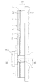
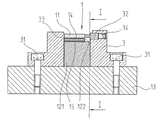
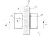
図1乃至4では、この発明の第一実施例が詳細に図示される。この場合には、図1は長さ測定装置の図を示し、測定方向Xに延びていて、即ち図2の縦断面IーIを示し、そし
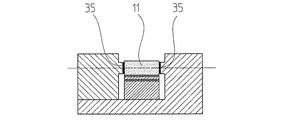
て図2は走査ユニットなしのこの測定装置の横断面IIーIIを示す。
1-4, the first embodiment of the present invention is illustrated in detail. In this case, FIG. 1 shows a diagram of the length measuring device, extending in the measuring direction X, ie showing the longitudinal section II of FIG. 2, and FIG. 2 crossing this measuring device without a scanning unit. Surface II-II is shown.
長さ測定装置は支持体12に取付けられた物差し11を備える第一構成ユニット1並びに以下で走査ユニット2と呼ばれる第二構成ユニットから成る。測定方向Xに位置測定するために、構成ユニット1が支持体12によって第一測定すべき物体13に、例えば工作機械のベットに固定されて、走査ユニット2が第二測定すべき物体21に、例えば工作機械のスライダに固定されている。この場合には、走査ユニット2が構成ユニット1に対して測定方向Xに移動できる。
The length measuring device comprises a first component unit 1 comprising a
物差し11は無視できない熱膨張係数を備える材料から成り、αは0°から50°までの温度範囲で特に0.1×1/106 ・1/Kより小さい。この材料は特に取引名「ZERODUR,SITAL とULE 」で知られている所謂零膨張を備えるガラスである。このガラスは金属に比べて、通常の製造方法によって良好な光学表面が製造でき、その光学表面に光学走査可能な測定区分が分布され得るという利点を有する。
The
例えばこの物差し11はその上面に光電走査可能な測定区分110を数nmの区分周期を備える直立に走査可能な区分格子の形態に支持する。この測定区分110は反射された位相格子であるか、或いは測定方向Xに交互に配置された反射と非反射の領域から成る。この測定区分110は位置測定するために、概略的にのみ図示された走査ユニット2によって走査される。
For example, the
物差し11は支持体12に固定手段によって固定され、この固定手段は支持体12の長さ膨張が物差し11に対して邪魔されずに可能とされるように形成されている。好ましい形式では、この固定手段が測定方向Xにおける僅かな剪断剛性を備える粘性中間層であり、この中間層を通して物差し11が支持体12に付着して保持される。図示された例では、この中間層が液状膜14であり、その液状膜を介して物差し11が毛細管現象によって支持体12の面に対して引かれて、液状膜14上に平らに載置する。この液状膜14は物差し11を一方では、確実に支持体12に保持し、しかし、他方では、物差し11に対して支持体12の移動が温度条件付き長さ変更によって摩擦のなく、それで力なしに引き起こされる。液状膜14用の材料として特に珪素油が適している。
The
支持体12は例えば曲げ強く、サンドイッチ状或いは層状に構成され、つまり複数の上下に配置された支持部分、特に第一支持部分121と第二支持部分122とから成り立つ。この第一支持部分121が安定で曲げ強く形成され、そして金属、特に0°から50°までの温度範囲で特に0.1×1/106 ・1/Kより小さい熱膨張係数αを備える鋼から成る。この第一支持部分121が第一測定すべき物体13に固定でき、例えばねじ止め或いは貼付けによって 固定できる。このために、この第一支持部分が測定すべき物体13に向いた側面に測定長さに渡って達する固定面を有し、第一支持部分が大きく平らで、それで耐振動的に測定すべき物体13に固定できる。
The
この第一支持部分121上には第二支持部分122が第二固定手段によって固定されている。好ましい形式では、この第二固定手段はさらに、例えば高弾性接着剤15の形態で測定方向Xにおいて僅かな剪断剛性を備える粘性中間層である。この第二支持部分122が中間支持体として作用し、液状膜14用の接触面を形成する。この目的のために、第二支持部分122が例えば0°から50°までの温度範囲でおよそ7−9×1/106 ・1/Kの熱膨張係数αを備えるフロートガラスから成るガラス薄板である。特に好ましくは、ガラス或いはガラスセラミックから成る物差しとガラスから成る第二支持部分122の使用であり、というのは、二枚のガラス面間に液状膜14を設けることは物差し11が特に均一に完全平らであり、それにより振動なく支承され得て、それが測定精度を高める利点を有するからである。
A
支持体12のサンドイッチ状構成は、異なった長さ膨張が温度変動によって引き起こされて、専ら唯一の固定手段によって形成されなければならないという利点を有する。このために、使用された材料の熱膨張係数が物差し11から出発して第一支持部分121まで段階的に段付けられている。即ち、物差し11の熱膨張係数が第二支持部分122の熱膨張係数より小さく、さらに、第二支持部分122の熱膨張係数が第一支持部分121の熱膨張係数より小さい。物差し11と第二支持部分122の間の異なった長さ変更が第一固定手段、例えば中間層の形態で、特に液状膜14によって摩擦のなく補償され、第二支持部分122と第一支持部分121の間の異なった長さ変更が第二固定手段、例えば中間層の形態で、特に弾性接着剤15によって補償される。
The sandwich-like configuration of the
しかし、示されていない形式では、支持体12が一部材で形成され得る。
However, in a form not shown, the
物差し11の所謂零点を形成するために、物差し11が固定点Pに保持体3によって測定すべき物体13に固定でき、例えばねじ31とピンの少なくとも一方によって固定できる。保持体3は、一方では、専ら物差し11が固定点Pに固定式に固定され、他方では、支持体12を避けてこの保持体3がさらに、測定方向Xにおけるある位置で測定すべき物体13に固定式に固定できるように、形成されている。それにより保持体3が一種の概念を物差し11から出発して測定すべき物体13にまで形成する。測定方向Xに作用する物差し11と支持体12の間の離脱が例えば液状膜14によって実現され、保持体3のこの構造によって固定点Pに保持されたままである。このために、この保持体3は、保持体が支持体12と接触しなく、締付け力のような強制力を物差し11と支持体12の間に及ぼさないように、形成されている。この措置によって物差し11と測定すべき物体13の間に熱安定固定点が測定方向Xにおいて創作され、固定点が支持体12から完全に離脱されている。
In order to form a so-called zero point of the
図2の横断面が示すように、保持体3の固定が少なくとも一つのねじ31或いはピンによって同じ箇所に、測定方向Xに観察して、物差し11と保持体3を固定するように、行われるならば、特に好ましい。
As shown in the cross section of FIG. 2, the holding
物差し11が固定点Pに保持体3に固定式に固定されていて、保持体3が支持体12の傍の横に測定すべき物体13にまで延びて配置されている。支持体12上への強制力を回避するために、保持体3が横に支持体12から間隔を置いて延びている。横とは、測定方向Xに対して垂直であり且つ物差し11、中間層14と支持体12が連続的に配置されている方向に垂直である方向を定義する。
A
固定点Pの位置にも、測定方向Xに観察して、物差し11が付着して形成された中間層を介して、例えば液状膜14として形成され、支持体12に支持して保持される。特に安定で振動なく構成を生じ、というのは、物差し11が全長さに渡って固定点を含めて平らに支持体12に付着して保持されているからであり、この場合には、支持体12が物差し11を全長さに渡って固定点を含めて支持する。
Also observed at the position of the fixed point P in the measuring direction X, is formed as, for example, a
保持体が互いに平行に延びている両縦側面に装着されるので、物差し11と保持体3の固定式固定は力一体化によって行われる。緊張要素32が物差し11の縦側面の一方に当置し、物差し11を対向位置する縦側面でストッパ33に押す付けるので、物差し11のこの装着が実現される。緊張要素32が少なくとも一つのねじ34によって測定方向Xを横切って移動でき、物差し11を固定式に保持体3にクリンチによって互いに対向位置する状態に締付けるスライダとして形成されている。
Since the holding body is mounted on both vertical side surfaces extending in parallel with each other, the fixed fixing of the
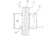
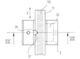
図3は前述の長さ測定装置に関する平面図を概略的に示す。 FIG. 3 schematically shows a plan view of the length measuring device described above.
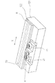
図4は、ここで図示されていない固定点から測定方向に間隔を置いて配置されている箇所における長さ測定装置の斜視図を概略的に示す。支持体12、つまり第一支持部分121と第二支持部分122並びに物差し11から成る構成ユニットが図示されている。明瞭性のために、中間層14と15が図示されていない。固定点から測定方向Xへ離れていて、物差し11の軸受4が配置されている。この軸受11が例えば案内ロール41を備えるロール軸受から成り、案内ロールが物差し11を縦側面に接触するので、物差し11の長さ変更が支持体12に対して出来るだけ摩擦のなく可能とされる。それにより軸受4が摩擦の乏しい縦案内を支持体12と物差し11の間に形成する。物差し11を整合するために、物差し11を案内ロール41に押付ける手段が設けられている。この押圧力は、例えば欧州特許第1004855号明細書に記載されるように、公知の形式でばね力或いは磁気力によって発生され得る。
FIG. 4 schematically shows a perspective view of the length measuring device at a location which is spaced from the fixed point not shown here in the measuring direction. A structural unit comprising the
次に、上記実施態様に選択的に、詳細に説明され、この場合には、部材、物差し、支持体、固定点と保持体のために、それぞれに上に説明された実施例におけると同じ参照符号が使用され、これに関して構造が相違していない。 Next, it will be described in detail selectively, in the above embodiment, in which case the same reference is made to the embodiment described above for the member, ruler, support, fixing point and holding body respectively. Signs are used and the structure is not different in this regard.
固定点Pにおける物差し11と保持体3の間の力一体に選択的に、固定式固定に対する材料一体或いは形状一体化も実現され得る。
As an alternative to the force integration between the
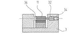
図5と6は概略的に材料一体化を示し、というのは、物差し11が固定点Pに接着剤35によって保持体3に固定式に固定されていて、さらに、保持体3が支持体12を避けて測定すべき物体13に固定できるからである。
5 and 6 schematically show material integration because the
図7と8は概略的に形状一体を示し、というのは、物差し11が固定点Pに形状一体的作用によって保持体3に固定式に固定されていて、さらに、保持体3が支持体12を避けて測定すべき物体13に固定式に固定できるからである。例えば保持体3の突起36が物差し11の窪み37に作用する。それにより発生された形状一体化が測定方向Xにおいて固定式に固定されている。
7 and 8 schematically show the integrated shape, because the
物差し11と保持体3の固定式固定のすべての構成では、物差し11の両縦側面への固定が物差し11の中心や測定区分110に対して対称的に行われるならば、特に好ましい。それにより局部的結合の保持力が対称的に物差し11に作用する。
In all configurations of the fixed fixing of the
さらに、物差し11に保持体3を固定することが物差し11の高さに関連して中心に、つまり物差し11の中立平面で行われるならば、特に好ましい。
Furthermore, it is particularly preferred if the holding
1.....構成ユニット
3.....保持体
4.....軸受
11....物差し
110...測定区分
12....支持体
121...第一支持部分
122...第二支持部分
13....測定すべき物体
14、15...中間層
32....緊張要素
33....ストッパ
34....ねじ
35....接着剤
36....突起
41....案内ロール
1. . . . . 2. Configuration unit . . . . Holding body 4. . . . .
Claims (8)
Applications Claiming Priority (2)
| Application Number | Priority Date | Filing Date | Title |
|---|---|---|---|
| DE102009044917A DE102009044917A1 (en) | 2009-09-23 | 2009-09-23 | Length measuring device |
| DE102009044917.5 | 2009-09-23 |
Publications (3)
| Publication Number | Publication Date |
|---|---|
| JP2011069813A JP2011069813A (en) | 2011-04-07 |
| JP2011069813A5 JP2011069813A5 (en) | 2013-05-23 |
| JP5479250B2 true JP5479250B2 (en) | 2014-04-23 |
Family
ID=43312561
Family Applications (1)
| Application Number | Title | Priority Date | Filing Date |
|---|---|---|---|
| JP2010159338A Active JP5479250B2 (en) | 2009-09-23 | 2010-07-14 | Length measuring device |
Country Status (6)
| Country | Link |
|---|---|
| US (1) | US8156658B2 (en) |
| EP (1) | EP2302332B1 (en) |
| JP (1) | JP5479250B2 (en) |
| CN (1) | CN102022962B (en) |
| DE (1) | DE102009044917A1 (en) |
| ES (1) | ES2593359T3 (en) |
Families Citing this family (9)
| Publication number | Priority date | Publication date | Assignee | Title |
|---|---|---|---|---|
| ES2618855T3 (en) * | 2014-10-14 | 2017-06-22 | Dr. Johannes Heidenhain Gmbh | Position measuring device with device for compensation of errors by thermal expansion of a graduated ruler |
| CN104457498A (en) * | 2014-12-19 | 2015-03-25 | 苏州莱测检测科技有限公司 | Bar length measurement device |
| CN108351205B (en) * | 2016-03-03 | 2020-12-01 | 株式会社东芝 | Measuring device |
| EP3399284B1 (en) * | 2017-05-03 | 2019-07-10 | Dr. Johannes Heidenhain GmbH | Sensor unit for position measurement |
| JP7148262B2 (en) * | 2018-04-19 | 2022-10-05 | 株式会社ミツトヨ | linear encoder |
| EP3705850B1 (en) | 2019-03-06 | 2021-12-29 | Etel S.A. | Assembly with a main beam, an intermediate support arranged on the main beam and a measuring rod on the intermediate support |
| CN112504198B (en) * | 2020-12-24 | 2022-06-17 | 深圳南玻应用技术有限公司 | Glass size measuring device and measuring method thereof |
| CN112985472B (en) * | 2021-05-21 | 2021-09-21 | 深圳清华大学研究院 | Contact type ultra-smooth encoder |
| GB202211615D0 (en) * | 2022-08-09 | 2022-09-21 | Renishaw Plc | Scale |
Family Cites Families (18)
| Publication number | Priority date | Publication date | Assignee | Title |
|---|---|---|---|---|
| DE3319600A1 (en) * | 1983-05-30 | 1984-12-06 | Dr. Johannes Heidenhain Gmbh, 8225 Traunreut | LENGTH MEASURING DEVICE |
| DE3719409A1 (en) * | 1987-06-11 | 1988-12-22 | Heidenhain Gmbh Dr Johannes | POSITION MEASURING DEVICE |
| DE3929629A1 (en) * | 1989-09-06 | 1991-03-07 | Zeiss Carl Fa | LENGTH OR ANGLE MEASURING DEVICE |
| JP2979666B2 (en) * | 1991-02-13 | 1999-11-15 | ソニー・プレシジョン・テクノロジー株式会社 | Scale equipment |
| DE4320728C2 (en) * | 1993-06-23 | 2001-08-02 | Heidenhain Gmbh Dr Johannes | Position measuring device |
| DE19512892C2 (en) * | 1995-04-06 | 1998-11-05 | Heidenhain Gmbh Dr Johannes | Position measuring device |
| DE19526517C2 (en) * | 1995-07-20 | 2000-08-24 | Zeiss Carl Jena Gmbh | Arrangement for attaching a length measuring device |
| DE19821558B4 (en) * | 1997-08-08 | 2007-09-13 | Dr. Johannes Heidenhain Gmbh | Scale and method for the production of a scale and position measuring device |
| DE19854318A1 (en) * | 1998-11-25 | 2000-05-31 | Heidenhain Gmbh Dr Johannes | Length measuring device |
| DE19914311A1 (en) * | 1999-03-29 | 2000-10-05 | Heidenhain Gmbh Dr Johannes | Method and device for attaching a scale |
| DE10106012A1 (en) * | 2001-02-09 | 2002-08-14 | Heidenhain Gmbh Dr Johannes | Angle measuring device |
| JP3806328B2 (en) * | 2001-09-27 | 2006-08-09 | 株式会社ミツトヨ | Unit-type linear displacement measuring device and end fixture thereof |
| DE10236381A1 (en) * | 2002-08-08 | 2004-02-19 | Dr. Johannes Heidenhain Gmbh | Length measurement instrument for a machine tool, comprises a housing that also forms the guide rail for a scanning unit carriage, with the guide rail aligned parallel to a machine tool guide using flexible elements |
| JP4223823B2 (en) * | 2003-02-10 | 2009-02-12 | ソニーマニュファクチュアリングシステムズ株式会社 | Scale equipment |
| DE502005005331D1 (en) * | 2005-06-08 | 2008-10-23 | Heidenhain Gmbh Dr Johannes | Encoder element of a measuring system |
| DE102005053088A1 (en) * | 2005-11-04 | 2007-05-10 | Dr. Johannes Heidenhain Gmbh | Scale attaching method for use in support, involves providing surfaces with adhesives between scale and support, and forming wringing surfaces in direct proximity to dosing channel, where wringing surfaces are separated from one another |
| CN101416031A (en) * | 2006-03-29 | 2009-04-22 | 约翰尼斯海登海恩博士股份有限公司 | Method for holding a scale on a carrier and arrangement having a carrier and a scale |
| JP5162800B2 (en) * | 2009-03-24 | 2013-03-13 | 株式会社ミツトヨ | Linear scale |
-
2009
- 2009-09-23 DE DE102009044917A patent/DE102009044917A1/en not_active Withdrawn
-
2010
- 2010-05-18 EP EP10163093.7A patent/EP2302332B1/en active Active
- 2010-05-18 ES ES10163093.7T patent/ES2593359T3/en active Active
- 2010-07-14 JP JP2010159338A patent/JP5479250B2/en active Active
- 2010-09-21 US US12/924,157 patent/US8156658B2/en active Active
- 2010-09-21 CN CN201010293102.9A patent/CN102022962B/en active Active
Also Published As
| Publication number | Publication date |
|---|---|
| EP2302332A3 (en) | 2012-11-28 |
| DE102009044917A1 (en) | 2011-04-07 |
| EP2302332B1 (en) | 2016-09-07 |
| CN102022962A (en) | 2011-04-20 |
| US20110067255A1 (en) | 2011-03-24 |
| ES2593359T3 (en) | 2016-12-07 |
| CN102022962B (en) | 2014-11-26 |
| EP2302332A2 (en) | 2011-03-30 |
| JP2011069813A (en) | 2011-04-07 |
| US8156658B2 (en) | 2012-04-17 |
Similar Documents
| Publication | Publication Date | Title |
|---|---|---|
| JP5479250B2 (en) | Length measuring device | |
| JP6650725B2 (en) | Length measuring device | |
| JP4931916B2 (en) | Scale holder | |
| JP3134590B2 (en) | Scale equipment | |
| JP5513497B2 (en) | Device for clamping and fixing the reference scale | |
| JP4525991B2 (en) | Length measuring device | |
| JP2944730B2 (en) | Length or angle measuring device | |
| JP5889737B2 (en) | Length measuring device | |
| JPH08285566A (en) | Position measuring device | |
| JPH11506217A (en) | Strip-like elastic flexible tape measure for length or angle measuring device | |
| US20090019948A1 (en) | Device for simultaneous measurement of forces | |
| CN101498571B (en) | Measuring apparatus | |
| JP5436658B2 (en) | Device having a scale fixed to a carrier and method for holding a scale on a carrier | |
| JP5112314B2 (en) | Sensor module for probe of tactile coordinate measuring device | |
| JP2007139592A (en) | Instrument of measuring ultramicro hardness or the like and measuring method | |
| JP2020144114A (en) | Device including main support, intermediate support disposed on the main support and scale disposed on the intermediate support | |
| US8853567B2 (en) | Electromagnetic force compensating weighing device with mounting system compensating for mechanical stresses | |
| JPH09236409A (en) | Measuring gauge for relative slippage amount | |
| JP5108289B2 (en) | Scale for displacement measuring device | |
| JP2005083920A (en) | Linear expansion coefficient measuring device | |
| JP3609271B2 (en) | Displacement measuring device | |
| JP2582210B2 (en) | Displacement measuring device | |
| US9933249B2 (en) | Dynamic mechanical analyzer and sample fixtures for a dynamic mechanical analyzer | |
| JP2005300316A (en) | Displacement measuring device | |
| JP2007170947A (en) | Fixture for thermomechanical analyzer, and thermomechanical analyzer |
Legal Events
| Date | Code | Title | Description |
|---|---|---|---|
| A521 | Request for written amendment filed |
Free format text: JAPANESE INTERMEDIATE CODE: A523 Effective date: 20130415 |
|
| A621 | Written request for application examination |
Free format text: JAPANESE INTERMEDIATE CODE: A621 Effective date: 20130415 |
|
| A977 | Report on retrieval |
Free format text: JAPANESE INTERMEDIATE CODE: A971007 Effective date: 20130805 |
|
| A131 | Notification of reasons for refusal |
Free format text: JAPANESE INTERMEDIATE CODE: A131 Effective date: 20130827 |
|
| A521 | Request for written amendment filed |
Free format text: JAPANESE INTERMEDIATE CODE: A523 Effective date: 20131112 |
|
| TRDD | Decision of grant or rejection written | ||
| A01 | Written decision to grant a patent or to grant a registration (utility model) |
Free format text: JAPANESE INTERMEDIATE CODE: A01 Effective date: 20140114 |
|
| A61 | First payment of annual fees (during grant procedure) |
Free format text: JAPANESE INTERMEDIATE CODE: A61 Effective date: 20140212 |
|
| R150 | Certificate of patent or registration of utility model |
Ref document number: 5479250 Country of ref document: JP Free format text: JAPANESE INTERMEDIATE CODE: R150 |
|
| R250 | Receipt of annual fees |
Free format text: JAPANESE INTERMEDIATE CODE: R250 |
|
| R250 | Receipt of annual fees |
Free format text: JAPANESE INTERMEDIATE CODE: R250 |
|
| R250 | Receipt of annual fees |
Free format text: JAPANESE INTERMEDIATE CODE: R250 |
|
| R250 | Receipt of annual fees |
Free format text: JAPANESE INTERMEDIATE CODE: R250 |
|
| R250 | Receipt of annual fees |
Free format text: JAPANESE INTERMEDIATE CODE: R250 |
|
| R250 | Receipt of annual fees |
Free format text: JAPANESE INTERMEDIATE CODE: R250 |
|
| R250 | Receipt of annual fees |
Free format text: JAPANESE INTERMEDIATE CODE: R250 |
|
| R250 | Receipt of annual fees |
Free format text: JAPANESE INTERMEDIATE CODE: R250 |