JP5478129B2 - Non-contact ultrasonic tonometer - Google Patents
Non-contact ultrasonic tonometer Download PDFInfo
- Publication number
- JP5478129B2 JP5478129B2 JP2009147124A JP2009147124A JP5478129B2 JP 5478129 B2 JP5478129 B2 JP 5478129B2 JP 2009147124 A JP2009147124 A JP 2009147124A JP 2009147124 A JP2009147124 A JP 2009147124A JP 5478129 B2 JP5478129 B2 JP 5478129B2
- Authority
- JP
- Japan
- Prior art keywords
- wave
- probe
- subject
- burst wave
- intraocular pressure
- Prior art date
- Legal status (The legal status is an assumption and is not a legal conclusion. Google has not performed a legal analysis and makes no representation as to the accuracy of the status listed.)
- Expired - Fee Related
Links
Images


Classifications
-
- A—HUMAN NECESSITIES
- A61—MEDICAL OR VETERINARY SCIENCE; HYGIENE
- A61B—DIAGNOSIS; SURGERY; IDENTIFICATION
- A61B3/00—Apparatus for testing the eyes; Instruments for examining the eyes
- A61B3/10—Objective types, i.e. instruments for examining the eyes independent of the patients' perceptions or reactions
- A61B3/16—Objective types, i.e. instruments for examining the eyes independent of the patients' perceptions or reactions for measuring intraocular pressure, e.g. tonometers
- A61B3/165—Non-contacting tonometers
-
- A—HUMAN NECESSITIES
- A61—MEDICAL OR VETERINARY SCIENCE; HYGIENE
- A61B—DIAGNOSIS; SURGERY; IDENTIFICATION
- A61B8/00—Diagnosis using ultrasonic, sonic or infrasonic waves
- A61B8/10—Eye inspection
Description
本発明は、超音波を用いて非接触で被検者眼の眼圧を測定する非接触式超音波眼圧計に関する。 The present invention relates to a non-contact ultrasonic tonometer that measures intraocular pressure of a subject's eye in a non-contact manner using ultrasonic waves.
近年、被検者眼の角膜に向けて超音波を出射する振動子と角膜で反射された超音波を検出するセンサとを有する探触子を備えて非接触で被検者眼の眼圧を測定する装置が提案されている(特許文献1参照)。 In recent years, a probe having a transducer for emitting ultrasonic waves toward the cornea of a subject's eye and a sensor for detecting ultrasonic waves reflected by the cornea has been provided, and the intraocular pressure of the subject's eye has been reduced without contact. An apparatus for measuring has been proposed (see Patent Document 1).
しかしながら、特許文献1の場合、被検者眼と装置との作動距離(ワーキングディスタンス)が短く、実際に人眼に対して眼圧を測定しようとすると、被検者眼との接触の可能性があり、また、被検者に対して恐怖心を与え易い。一方、作動距離を長くすると、検出信号のS/N比が低下し、測定精度が落ちる。 However, in the case of Patent Document 1, if the working distance between the subject's eye and the device is short, and actually trying to measure the intraocular pressure for the human eye, there is a possibility of contact with the subject's eye. In addition, it is easy to give fear to the subject. On the other hand, when the working distance is lengthened, the S / N ratio of the detection signal is lowered and the measurement accuracy is lowered.
本発明は、上記従来技術を鑑み、被検者眼に対する作動距離を確保しつつ、精度良く眼圧を測定できる非接触式超音波眼圧計を提供することを技術課題とする。 In view of the above-described prior art, an object of the present invention is to provide a non-contact ultrasonic tonometer that can accurately measure intraocular pressure while ensuring a working distance with respect to the subject's eye.
上記課題を解決するために、本発明は以下のような構成を備えることを特徴とする。 In order to solve the above problems, the present invention is characterized by having the following configuration.
(1)
被検者眼から離れた位置に配置され、空気を媒体として被検者眼の角膜に超音波を出射し、角膜で反射された超音波を反射波として検出する探触子、を備える非接触式超音波眼圧計において、
前記探触子の駆動を制御し,被検者眼角膜に向けて前記超音波をバースト波として送信するバースト波送信手段と、
前記探触子からの出力信号に基づいて前記バースト波の反射出力を取得し、該反射出力に基づいて眼圧を求める演算手段と、を備え、
前記バースト波送信手段は、前記バースト波を複数回被検者眼に向けて出射し、
前記演算手段は、各バースト波の反射出力をそれぞれ取得し、該反射出力に基づいて各バースト波に対応する眼圧をそれぞれ求めることを特徴とする。
(2)
(1)の非接触式超音波眼圧計において、
前記演算手段は、前記探触子からの出力信号に基づいて前記バースト波の反射波における周波数毎の振幅レベルである振幅スペクトル情報を取得し、該振幅スペクトル情報に基づいて眼圧を求めることを特徴とする。
(3)
(1)の非接触式超音波眼圧計において、
撮像素子を有し、被検者眼の前眼部を観察する観察光学系を備えることを特徴とする。
(1)
A non-contact probe that is disposed at a position away from the subject's eye and that emits ultrasonic waves to the cornea of the subject's eyes using air as a medium and detects the ultrasonic waves reflected by the cornea as reflected waves Type ultrasonic tonometer,
Burst wave transmitting means for controlling the driving of the probe and transmitting the ultrasonic wave as a burst wave toward the subject's cornea;
Obtaining a reflection output of the burst wave based on an output signal from the probe, and calculating means for obtaining an intraocular pressure based on the reflection output ,
The burst wave transmitting means emits the burst wave toward the subject's eye a plurality of times,
The computing means obtains the reflected output of each burst wave, and obtains the intraocular pressure corresponding to each burst wave based on the reflected output .
(2)
In the non-contact ultrasonic tonometer of (1),
Said calculating means, based on an output signal from the probe to acquire an amplitude spectrum information is the amplitude level of each frequency in the reflection wave of the burst wave, the determination of the intraocular pressure based on the amplitude spectrum information Features.
(3)
In the non-contact ultrasonic tonometer of (1),
It has an imaging device and is provided with an observation optical system for observing the anterior segment of the subject's eye.
本発明によれば、被検者眼に対する作動距離を確保しつつ、精度良く眼圧を測定できる。 According to the present invention, it is possible to accurately measure intraocular pressure while ensuring a working distance with respect to the subject's eye.
以下、本発明の一実施形態について図面に基づいて説明する。図1は本実施形態に係る非接触式超音波眼圧計の概略外観図であり、図2は本装置の制御系の概略ブロック図である。 Hereinafter, an embodiment of the present invention will be described with reference to the drawings. FIG. 1 is a schematic external view of a non-contact ultrasonic tonometer according to this embodiment, and FIG. 2 is a schematic block diagram of a control system of this apparatus.
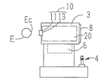
図1において、本体部(装置本体)3には、被検者眼Eから離れた位置に配置される探触子(トランスデューサ)10と、撮像素子を有して被検者眼Eの前眼部を観察する観察光学系20と、が設けられている。また、本体部3の筐体内には、図示なきアライメント光学系及び固視光学系等が設けられている。モニタ8は、観察光学系20の撮像素子によって撮像された前眼部像、測定結果、等を表示する。モニタ8に表示された前眼部像を観察しながら検者がジョイスティック4を操作すると、その操作信号に基づいて駆動部6が駆動され、本体部3が三次元的に移動される。これにより、被検者眼Eに対する本体部3のアライメントが行われる。
In FIG. 1, a main body (apparatus main body) 3 has a probe (transducer) 10 disposed at a position distant from the subject eye E and an anterior eye of the subject eye E having an image sensor. And an observation
探触子10は、空気を媒体として被検者眼Eの角膜Ecに向けて超音波パルスを出射し、また、角膜Ecで反射された超音波パルスを反射波として検出する。探触子10は、被検者眼Eに入射させる超音波(入射波)を出射する振動子(超音波送信部)11と、被検者眼Eで反射された超音波(反射波)を検出する振動検出センサ(超音波受信部)13と、を有し、被検者眼Eの眼圧を非接触で測定するために用いられる。なお、本実施形態の探触子10は、制御部70の制御によって振動子11の動作とセンサ13の動作とを兼ねるものとなっている。もちろん、これに限るものではなく、振動子11とセンサ13とが別構成であってもよい。
The
また、探触子10(超音波送受信部)には、空気中での伝播効率を高めるために、広帯域の周波数成分を持つ超音波ビームを送受信する空気結合型の超音波探触子が用いられることが好ましい。この場合、(マイクロアコースティック(Microacoustic)社のBATTM探触子を用いることができる)。このような探触子の詳細については、米国特許5287331号公報、特表2005−506783号公報、等を参照されたい。もちろん、これに限るものではなく、ピエゾ型の超音波探触子が用いられてもよい。 In addition, an air-coupled ultrasonic probe that transmits and receives an ultrasonic beam having a broadband frequency component is used for the probe 10 (ultrasonic transmission / reception unit) in order to increase propagation efficiency in the air. It is preferable. In this case (a Microacoustic BAT ™ probe can be used). For details of such a probe, refer to US Pat. No. 5,287,331, JP 2005-506783 A and the like. Of course, the present invention is not limited to this, and a piezoelectric ultrasonic probe may be used.
図2において、制御部70は、測定値の算出、装置全体の制御、等を行う。制御部70は、探触子10からの出力信号を処理して被検者眼Eの眼圧を求める。探触子10は増幅器81に接続されており、探触子10から出力される電気信号は増幅器81によって増幅され、制御部70に入力される。また、制御部70は、探触子10、観察光学系20の各部材(光源、撮像素子、等)、駆動部6、モニタ8、メモリ75、等と接続されている。なお、メモリ75には、探触子10を用いて眼圧を測定するための測定プログラム、装置全体の制御を行うための制御プログラム、等が記憶されている。
In FIG. 2, the
以下に、探触子10を制御して被検者眼Eに向けてバースト波を送信し、そのバースト波の反射波におけるスペクトル情報に基づいて眼圧を測定する手法について説明する。
Hereinafter, a method of controlling the
制御部70は、探触子10からバースト波を送信させるために、探触子10の振動子をバースト駆動する。このバースト駆動により、探触子10からは、超音波パルスが一定周期1/T(Tはバースト周波数)でK回繰り返し送信される。なお、Kはバースト波数であり、パルス波のサイクル数を表す。このようなK個の超音波パルスのまとまりを、バースト波とする。
The
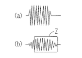
図3は空気中に出射されたバースト波の振幅レベルの時間変化を示す波形図である。図3(a)は、広帯域空気結合超音波探触子を用いた場合の波形である。この場合、探触子の構造上、バースト波送信時の残響特性の影響を受けないため、各パルス波の波形が均一である。図3(b)は、セラミック圧電探触子(圧電素子型探触子)を用いた場合の波形である。この場合、バースト波送信時の残響特性の影響により、各パルス波の波形が乱れる可能性がある(図3(b)の枠Z参照)。なお、セラミック圧電探触子であっても、複合圧電材料(例えば、樹脂シート中に圧電セラミックス柱が埋め込まれたもの)を用いたコンポジット型広帯域超音波探触子の使用によって残響特性の影響を軽減できる。 FIG. 3 is a waveform diagram showing temporal changes in the amplitude level of the burst wave emitted into the air. FIG. 3A shows a waveform when a broadband air-coupled ultrasonic probe is used. In this case, the waveform of each pulse wave is uniform because the probe structure is not affected by the reverberation characteristics during burst wave transmission. FIG. 3B shows a waveform when a ceramic piezoelectric probe (piezoelectric element type probe) is used. In this case, the waveform of each pulse wave may be disturbed due to the influence of reverberation characteristics during burst wave transmission (see frame Z in FIG. 3B). Even with ceramic piezoelectric probes, the effects of reverberation characteristics are affected by the use of composite broadband ultrasonic probes that use composite piezoelectric materials (for example, piezoelectric ceramic columns embedded in resin sheets). Can be reduced.
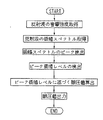
図4は、眼圧測定手法の一例を示すフローチャートである。所定のトリガ信号が出力されると、制御部70は、探触子10を制御し、バースト波を出射させる。角膜Ecに向けてバースト波が出射され、反射波がセンサ13によって検出されると、反射波の音響強度(振幅レベル)に対応する電気信号がセンサ13から出力され、増幅器81を介して制御部70に入力される。
FIG. 4 is a flowchart illustrating an example of an intraocular pressure measurement method. When a predetermined trigger signal is output, the
次に、制御部70は、検出された反射波の音響強度を周波数解析(例えば、フーリエ解析)し、反射波における周波数毎の振幅レベルである振幅スペクトルを取得する。なお、フーリエ解析を行う際の窓関数(例えば、矩形窓)の時間領域は、バースト波による角膜反射波の検出時間を含むように設定される。図5は反射波の振幅スペクトルの例である。
Next, the
ここで、制御部70は、得られた振幅スペクトルのピーク振幅レベル(例えば、図5における振幅スペクトルSのピーク値P)を検出する。そして、制御部70は、振幅スペクトルのピーク振幅レベルに基づいて眼圧を算出する。メモリ75には、ピーク振幅レベルと眼圧値との相関関係がテーブルとして記憶されており、制御部70は、検出されたピーク振幅レベルに対応する眼圧値をメモリ75から取得し、得られた眼圧値をモニタ8に表示する。なお、ピーク振幅レベルと眼圧値との相関関係は、例えば、本装置によって取得されるピーク振幅レベルとゴールドマン眼圧計によって得られる眼圧値との相関関係を予め求めておくことにより設定可能である。
Here, the
以上のような構成とすれば、被検者眼に対する作動距離が長くても(例えば、10mm程度)S/N比が確保され、安定した測定結果を得ることができる。より具体的には、バースト波による反射波のスペクトル情報は、各パルス波によるスペクトル情報が積算されたものとなるため、ピーク振幅レベルのS/N比が向上される。この場合、被検者眼の眼圧値の違いによるピーク振幅レベルの変化量が大きくなり、信頼度の高い眼圧値が得られる。 With the configuration as described above, even when the working distance to the subject's eye is long (for example, about 10 mm), the S / N ratio is ensured, and a stable measurement result can be obtained. More specifically, since the spectrum information of the reflected wave by the burst wave is obtained by integrating the spectrum information by each pulse wave, the S / N ratio of the peak amplitude level is improved. In this case, the amount of change in the peak amplitude level due to the difference in the intraocular pressure value of the subject's eye increases, and a highly reliable intraocular pressure value is obtained.
なお、上記構成において、制御部70は、探触子10を用いて、所定の時間間隔でバースト波を複数回被検者眼に向けて出射し、各バースト波に対応する反射波における振幅スペクトルに基づいて眼圧を求めてもよい(図6参照)。図6(a)は、広帯域空気結合超音波探触子を用いた場合の波形であり、図6(b)は、セラミック圧電探触子(圧電素子型探触子)を用いた場合の波形である。図6において、第1バースト波BW1、第2バースト波BW2、第3バースト波B3は、探触子10から順次連続的に出射される。そして、この場合、各バースト波(バースト波BW1、BW2、B3)に対応する反射波における振幅スペクトルがそれぞれ取得され、各振幅スペクトルに基づいてそれぞれ眼圧値が算出される。なお、制御部70は、各測定値に基づいて、代表値(例えば、各測定値の平均値、各測定値における中心値)を算出し、これをモニタ72等に出力してもよい。また、上記のように連続で眼圧を複数回測定する場合、被検者の脈動による測定値の変動を示した眼圧値の分布が得られるようにバースト波間の出射間隔及び出射時間が設定されるのが好ましい。
In the above configuration, the
なお、広帯域空気結合超音波探触子を用いた場合、各バースト波の休止時間Thにおいて残響特性の影響を受けないため、角膜反射波とそれ以外との判別が容易になる。したがって、角膜反射波に対するフーリエ解析を確実に実行できるため、バースト波による連続測定を行う場合に有用である。 When a broadband air-coupled ultrasonic probe is used, it is not affected by the reverberation characteristics in the pause time Th of each burst wave, so that it is easy to distinguish the corneal reflection wave from the rest. Therefore, since the Fourier analysis with respect to the corneal reflection wave can be surely executed, it is useful when performing continuous measurement using a burst wave.
なお、上記構成において、バースト周波数T及びバースト波数(パルス波のサイクル数)Kの少なくともどちらかは、制御部70によって任意に変更できるようにするのが好ましい。個々の探触子の違いにより超音波の特性にバラツキが生じるからである。この場合、振幅スペクトルのピーク振幅レベルのS/Nが高くなるようにバースト周波数T及びバースト波数Kを設定すればよい。また、バースト波の発生回数をメモリに記憶したり、モニタに表示するようにしてもよい。
In the above configuration, it is preferable that at least one of the burst frequency T and the burst wave number (number of pulse wave cycles) K can be arbitrarily changed by the
なお、以上の説明において、振幅スペクトルのピークが得られる周波数(中心周波数)を予め求めておき、これがメモリ75に記憶されていてもよい。そして、予め設定された周波数に対応する振幅レベルを振幅スペクトルのピーク振幅レベルとして取得し、これに基づいて眼圧を算出するようにしてもよい。また、振幅スペクトルにおけるピークを含む所定の周波数帯域における振幅レベルをピーク振幅レベルとして取得し、これに基づいて眼圧を求めるようにしてもよい。
In the above description, the frequency (center frequency) at which the peak of the amplitude spectrum is obtained may be obtained in advance and stored in the
なお、以上の説明においては、振幅スペクトルに基づいて眼圧を算出したが、角膜反射波を周波数解析したときの位相スペクトルに基づいて眼圧を算出してもよい。より具体的には、入射波と反射波のスペクトル分布を求め、所定の周波数における入射波の位相と反射波の位相との位相差を基に眼圧値を算出する。なお、前述した超音波パルス法による硬さ検出手法については、特開2002−272743号公報を参照されたい。 In the above description, the intraocular pressure is calculated based on the amplitude spectrum. However, the intraocular pressure may be calculated based on the phase spectrum when the corneal reflection wave is subjected to frequency analysis. More specifically, the spectral distribution of the incident wave and the reflected wave is obtained, and the intraocular pressure value is calculated based on the phase difference between the phase of the incident wave and the phase of the reflected wave at a predetermined frequency. For the hardness detection method using the ultrasonic pulse method described above, refer to Japanese Patent Application Laid-Open No. 2002-272743.
また、以上の説明においては、探触子10によって検出された波形のフーリエ解析に用いる窓関数を矩形窓としたが、これに限るものではなく、任意の窓関数(例えば、ハニング窓、ハミング窓、等)を用いることができる。
In the above description, the window function used for Fourier analysis of the waveform detected by the
また、以上の説明においては、バースト波の反射波におけるスペクトル情報に基づき眼圧を算出したが、これに限るものではなく、バースト波の反射出力に基づき眼圧が算出される構成であればよい。例えば、各パルス波による反射波の振幅強度に基づき眼圧が算出される。 In the above description, the intraocular pressure is calculated based on the spectrum information in the reflected wave of the burst wave. However, the present invention is not limited to this, and any configuration may be used as long as the intraocular pressure is calculated based on the reflected output of the burst wave. . For example, the intraocular pressure is calculated based on the amplitude intensity of the reflected wave by each pulse wave.
また、以上の説明では、ソフトウェアによる演算処理を用いて眼圧を求めるものとしたが、これに限るものではなく、ハードウェア(回路構成)による信号処理を用いて同様の処理が行われるようにしてもよい。 Further, in the above description, the intraocular pressure is obtained using a calculation process by software. However, the present invention is not limited to this, and the same process is performed using signal processing by hardware (circuit configuration). May be.
10 探触子
70 制御部
10
Claims (3)
前記探触子の駆動を制御し,被検者眼角膜に向けて前記超音波をバースト波として送信するバースト波送信手段と、
前記探触子からの出力信号に基づいて前記バースト波の反射出力を取得し、該反射出力に基づいて眼圧を求める演算手段と、を備え、
前記バースト波送信手段は、前記バースト波を複数回被検者眼に向けて出射し、
前記演算手段は、各バースト波の反射出力をそれぞれ取得し、該反射出力に基づいて各バースト波に対応する眼圧をそれぞれ求めることを特徴とする非接触式超音波眼圧計。 A non-contact probe that is disposed at a position away from the subject's eye and that emits ultrasonic waves to the cornea of the subject's eyes using air as a medium and detects the ultrasonic waves reflected by the cornea as reflected waves Type ultrasonic tonometer,
Burst wave transmitting means for controlling the driving of the probe and transmitting the ultrasonic wave as a burst wave toward the subject's cornea;
Obtaining a reflection output of the burst wave based on an output signal from the probe, and calculating means for obtaining an intraocular pressure based on the reflection output ,
The burst wave transmitting means emits the burst wave toward the subject's eye a plurality of times,
The non-contact ultrasonic tonometer is characterized in that the computing means obtains the reflected output of each burst wave and obtains the intraocular pressure corresponding to each burst wave based on the reflected output .
前記演算手段は、前記探触子からの出力信号に基づいて前記バースト波の反射波における周波数毎の振幅レベルである振幅スペクトル情報を取得し、該振幅スペクトル情報に基づいて眼圧を求めることを特徴とする非接触式超音波眼圧計。 In the non-contact ultrasonic tonometer according to claim 1,
Said calculating means, based on an output signal from the probe to acquire an amplitude spectrum information is the amplitude level of each frequency in the reflection wave of the burst wave, the determination of the intraocular pressure based on the amplitude spectrum information A non-contact ultrasonic tonometer.
撮像素子を有し、被検者眼の前眼部を観察する観察光学系を備えることを特徴とする非接触式超音波眼圧計。 The non-contact ultrasonic tonometer according to claim 1,
A non-contact ultrasonic tonometer comprising an imaging optical element and an observation optical system for observing an anterior segment of a subject's eye.
Priority Applications (4)
| Application Number | Priority Date | Filing Date | Title |
|---|---|---|---|
| JP2009147124A JP5478129B2 (en) | 2009-06-22 | 2009-06-22 | Non-contact ultrasonic tonometer |
| US12/817,850 US20100324406A1 (en) | 2009-06-22 | 2010-06-17 | Non-contact ultrasonic tonometer |
| CN2010102178000A CN101926659A (en) | 2009-06-22 | 2010-06-22 | Non-contact ultrasonic tonometer |
| EP10166888A EP2266454A1 (en) | 2009-06-22 | 2010-06-22 | Non-contact ultrasonic tonometer |
Applications Claiming Priority (1)
| Application Number | Priority Date | Filing Date | Title |
|---|---|---|---|
| JP2009147124A JP5478129B2 (en) | 2009-06-22 | 2009-06-22 | Non-contact ultrasonic tonometer |
Publications (3)
| Publication Number | Publication Date |
|---|---|
| JP2011000344A JP2011000344A (en) | 2011-01-06 |
| JP2011000344A5 JP2011000344A5 (en) | 2012-08-02 |
| JP5478129B2 true JP5478129B2 (en) | 2014-04-23 |
Family
ID=42357803
Family Applications (1)
| Application Number | Title | Priority Date | Filing Date |
|---|---|---|---|
| JP2009147124A Expired - Fee Related JP5478129B2 (en) | 2009-06-22 | 2009-06-22 | Non-contact ultrasonic tonometer |
Country Status (4)
| Country | Link |
|---|---|
| US (1) | US20100324406A1 (en) |
| EP (1) | EP2266454A1 (en) |
| JP (1) | JP5478129B2 (en) |
| CN (1) | CN101926659A (en) |
Families Citing this family (11)
| Publication number | Priority date | Publication date | Assignee | Title |
|---|---|---|---|---|
| JP5917805B2 (en) | 2011-01-05 | 2016-05-18 | ソニー株式会社 | Information processing apparatus, information processing method, and computer program |
| KR101233966B1 (en) | 2011-01-19 | 2013-02-18 | 주식회사 휴비츠 | Method for measuring intraocular pressure |
| US20130342810A1 (en) * | 2012-06-04 | 2013-12-26 | Seiko Epson Corporation | Eyeball biological information collection device and method for collecting eyeball biological information |
| US20150148648A1 (en) * | 2013-11-22 | 2015-05-28 | Johnson & Johnson Vision Care, Inc. | Ophthalmic lens with intraocular pressure monitoring system |
| FI20145205L (en) * | 2014-03-04 | 2015-09-05 | Photono Oy | Method and system for intraocular pressure measurements |
| US20170332922A1 (en) * | 2016-05-18 | 2017-11-23 | Welch Allyn, Inc. | Stroke detection using ocular pulse estimation |
| DE102016121105A1 (en) * | 2016-11-04 | 2018-05-09 | Endress+Hauser Conducta Gmbh+Co. Kg | Interface for a transmitter |
| US20210068656A1 (en) * | 2018-03-30 | 2021-03-11 | Nidek Co., Ltd. | Non-contact ultrasonic ophthalmotonometer |
| JP7119597B2 (en) * | 2018-06-04 | 2022-08-17 | 株式会社ニデック | ultrasonic tonometer |
| JP7421069B2 (en) | 2019-12-04 | 2024-01-24 | 株式会社ニデック | ultrasonic tonometer |
| CN112603375A (en) * | 2021-01-21 | 2021-04-06 | 浙江爱视博医疗科技有限公司 | Mobile ultrasonic eye scanning equipment |
Family Cites Families (21)
| Publication number | Priority date | Publication date | Assignee | Title |
|---|---|---|---|---|
| US3690158A (en) * | 1970-05-06 | 1972-09-12 | Bernard Lichtenstein | Means and method for detection of glaucoma |
| US3948248A (en) * | 1974-09-05 | 1976-04-06 | Zuckerman Joel L | Method of measuring ocular pulse |
| JPS57179745A (en) * | 1981-04-30 | 1982-11-05 | Fujitsu Ltd | Method and device for measuring material property by ultrasonic wave |
| US4564018A (en) * | 1982-10-28 | 1986-01-14 | Storz Instrument Company | Ultrasonic system for obtaining ocular measurements |
| US4764006A (en) * | 1985-09-13 | 1988-08-16 | Canon Kabushiki Kaisha | Ophthalmic measuring apparatus |
| US4928697A (en) * | 1988-09-28 | 1990-05-29 | The Ohio State University | Non-contact high frequency tonometer |
| JPH0378653A (en) * | 1989-08-23 | 1991-04-03 | Olympus Optical Co Ltd | Ultrasonic microscope |
| US5251627A (en) * | 1991-06-27 | 1993-10-12 | Morris Donald E | Non-invasive measurement of eyeball pressure using vibration |
| JPH05253190A (en) * | 1991-10-10 | 1993-10-05 | Massie Res Lab Inc | Non-contact type tonometer |
| JPH05126806A (en) * | 1991-10-30 | 1993-05-21 | Olympus Optical Co Ltd | Ultrasonic-wave measuring apparatus |
| AU3263493A (en) * | 1992-01-11 | 1993-08-03 | Paul Toleman | Tonometer |
| US5287331A (en) * | 1992-10-26 | 1994-02-15 | Queen's University | Air coupled ultrasonic transducer |
| US5375595A (en) * | 1993-03-17 | 1994-12-27 | The Regents Of The University Of Calif. | Apparatus and method for non-contact, acoustic resonance determination of intraocular pressure |
| GB9308286D0 (en) * | 1993-04-22 | 1993-06-09 | Toleman Paul | Tonometer |
| US5865742A (en) * | 1995-03-06 | 1999-02-02 | Massie Research Laboratories, Inc. | Non-contact tonometer |
| US6030343A (en) * | 1997-09-03 | 2000-02-29 | Pgvc Lp | Single beam tone burst ultrasonic non contact tonometer and method of measuring intraocular pressure |
| JP4709984B2 (en) * | 2001-03-19 | 2011-06-29 | 学校法人日本大学 | Substance characteristic measuring method and substance characteristic measuring device |
| US6673014B2 (en) * | 2001-10-05 | 2004-01-06 | Itonix, Inc. | Noninvasive methods and apparatuses for measuring the intraocular pressure of a mammal eye |
| WO2003035281A2 (en) | 2001-10-23 | 2003-05-01 | Schindel David W | Ultrasonic printed circuit board transducer |
| WO2008072527A1 (en) * | 2006-12-08 | 2008-06-19 | Nihon University | Intraocular pressure measuring device |
| JP5478230B2 (en) * | 2009-03-31 | 2014-04-23 | 株式会社ニデック | Non-contact ultrasonic tonometer |
-
2009
- 2009-06-22 JP JP2009147124A patent/JP5478129B2/en not_active Expired - Fee Related
-
2010
- 2010-06-17 US US12/817,850 patent/US20100324406A1/en not_active Abandoned
- 2010-06-22 EP EP10166888A patent/EP2266454A1/en not_active Withdrawn
- 2010-06-22 CN CN2010102178000A patent/CN101926659A/en active Pending
Also Published As
| Publication number | Publication date |
|---|---|
| EP2266454A1 (en) | 2010-12-29 |
| CN101926659A (en) | 2010-12-29 |
| US20100324406A1 (en) | 2010-12-23 |
| JP2011000344A (en) | 2011-01-06 |
Similar Documents
| Publication | Publication Date | Title |
|---|---|---|
| JP5478129B2 (en) | Non-contact ultrasonic tonometer | |
| JP5478230B2 (en) | Non-contact ultrasonic tonometer | |
| US11659994B2 (en) | Method and arrangement for eye pressure measurements | |
| JP7134999B2 (en) | Device and method for measuring viscoelastic properties of viscoelastic media | |
| US11246570B2 (en) | Probe for transient elastography | |
| WO2017071605A1 (en) | Elasticity detection method and device | |
| AU2019228303B2 (en) | Hybrid elastography method, probe, and device for hybrid elastography | |
| TWI449518B (en) | System for detecting irregular bone defects during dental implant osseointegration process and control method thereof | |
| JP5397669B2 (en) | Non-contact ultrasonic tonometer | |
| JP2008183414A (en) | Apparatus for measuring circulation movement, method for circulation movement, blood pressure measurement method, and sensor for circulation movement | |
| CN110831505A (en) | Method for measuring ultrasound attenuation parameters guided by harmonic elastography, probe and device for implementing the method | |
| CN113117266B (en) | Temperature monitoring equipment | |
| JP2011030755A (en) | Non-contact ultrasonic tonometer | |
| JP2011055902A (en) | Ultrasonic diagnostic apparatus and method | |
| JPH07327994A (en) | Ultrasonic sebum thickness measuring instrument | |
| KR101027600B1 (en) | Ultrasonic diagnosis apparatus and controlling method for the same |
Legal Events
| Date | Code | Title | Description |
|---|---|---|---|
| A521 | Written amendment |
Free format text: JAPANESE INTERMEDIATE CODE: A523 Effective date: 20120620 |
|
| A621 | Written request for application examination |
Free format text: JAPANESE INTERMEDIATE CODE: A621 Effective date: 20120620 |
|
| A977 | Report on retrieval |
Free format text: JAPANESE INTERMEDIATE CODE: A971007 Effective date: 20130628 |
|
| A131 | Notification of reasons for refusal |
Free format text: JAPANESE INTERMEDIATE CODE: A131 Effective date: 20130709 |
|
| A521 | Written amendment |
Free format text: JAPANESE INTERMEDIATE CODE: A523 Effective date: 20130909 |
|
| TRDD | Decision of grant or rejection written | ||
| A01 | Written decision to grant a patent or to grant a registration (utility model) |
Free format text: JAPANESE INTERMEDIATE CODE: A01 Effective date: 20140114 |
|
| A61 | First payment of annual fees (during grant procedure) |
Free format text: JAPANESE INTERMEDIATE CODE: A61 Effective date: 20140210 |
|
| R150 | Certificate of patent or registration of utility model |
Ref document number: 5478129 Country of ref document: JP Free format text: JAPANESE INTERMEDIATE CODE: R150 |
|
| R250 | Receipt of annual fees |
Free format text: JAPANESE INTERMEDIATE CODE: R250 |
|
| R250 | Receipt of annual fees |
Free format text: JAPANESE INTERMEDIATE CODE: R250 |
|
| R250 | Receipt of annual fees |
Free format text: JAPANESE INTERMEDIATE CODE: R250 |
|
| LAPS | Cancellation because of no payment of annual fees |