JP5458865B2 - Image processing apparatus, imaging apparatus, image processing method, and program - Google Patents
Image processing apparatus, imaging apparatus, image processing method, and program Download PDFInfo
- Publication number
- JP5458865B2 JP5458865B2 JP2009288018A JP2009288018A JP5458865B2 JP 5458865 B2 JP5458865 B2 JP 5458865B2 JP 2009288018 A JP2009288018 A JP 2009288018A JP 2009288018 A JP2009288018 A JP 2009288018A JP 5458865 B2 JP5458865 B2 JP 5458865B2
- Authority
- JP
- Japan
- Prior art keywords
- image
- pixel
- motion region
- motion
- exposure
- Prior art date
- Legal status (The legal status is an assumption and is not a legal conclusion. Google has not performed a legal analysis and makes no representation as to the accuracy of the status listed.)
- Expired - Fee Related
Links
Images


Classifications
-
- G—PHYSICS
- G06—COMPUTING; CALCULATING OR COUNTING
- G06T—IMAGE DATA PROCESSING OR GENERATION, IN GENERAL
- G06T7/00—Image analysis
- G06T7/20—Analysis of motion
- G06T7/254—Analysis of motion involving subtraction of images
-
- G—PHYSICS
- G06—COMPUTING; CALCULATING OR COUNTING
- G06T—IMAGE DATA PROCESSING OR GENERATION, IN GENERAL
- G06T2207/00—Indexing scheme for image analysis or image enhancement
- G06T2207/10—Image acquisition modality
- G06T2207/10141—Special mode during image acquisition
- G06T2207/10144—Varying exposure
-
- G—PHYSICS
- G06—COMPUTING; CALCULATING OR COUNTING
- G06T—IMAGE DATA PROCESSING OR GENERATION, IN GENERAL
- G06T2207/00—Indexing scheme for image analysis or image enhancement
- G06T2207/20—Special algorithmic details
- G06T2207/20172—Image enhancement details
- G06T2207/20208—High dynamic range [HDR] image processing
Landscapes
- Engineering & Computer Science (AREA)
- Multimedia (AREA)
- Computer Vision & Pattern Recognition (AREA)
- Physics & Mathematics (AREA)
- General Physics & Mathematics (AREA)
- Theoretical Computer Science (AREA)
- Studio Devices (AREA)
- Image Processing (AREA)
- Editing Of Facsimile Originals (AREA)
- Image Analysis (AREA)
Description
本発明は、画像処理装置、撮像装置、および画像処理方法、並びにプログラムに関する。特に、複数の露光時間の異なる画像を利用した画像合成処理によりダイナミックレンジの広い高品質な出力画像を生成する画像処理装置、撮像装置、および画像処理方法、並びにプログラムに関する。 The present invention relates to an image processing device, an imaging device, an image processing method, and a program. In particular, the present invention relates to an image processing device, an imaging device, an image processing method, and a program that generate a high-quality output image with a wide dynamic range by image combining processing using a plurality of images having different exposure times.
ビデオカメラやデジタルスチルカメラなどに用いられるCCDイメージセンサやCMOS(Complementary Metal Oxide Semiconductor)イメージセンサのような固体撮像素子は入射光量に応じた電荷を蓄積し、蓄積した電荷に対応する電気信号を出力する光電変換を行う。しかし、光電変換素子における電荷蓄積量には上限があり、一定以上の光量を受けると蓄積電荷量が飽和レベルに達してしまい、一定以上の明るさの被写体領域は飽和した輝度レベルに設定されるいわゆる白とびが発生してしまう。 Solid-state image sensors such as CCD image sensors and CMOS (Complementary Metal Oxide Semiconductor) image sensors used in video cameras and digital still cameras store charges according to the amount of incident light, and output electrical signals corresponding to the stored charges. Perform photoelectric conversion. However, there is an upper limit for the amount of charge stored in the photoelectric conversion element, and the amount of stored charge reaches a saturation level when the amount of light exceeds a certain level, and the subject area with a certain level of brightness is set to a saturated luminance level. So-called overexposure occurs.
このような現象を防止するため、外光の変化等に応じて、光電変換素子における電荷蓄積期間を制御して露光時間を調整し、感度を最適値に制御するといった処理が行なわれる。例えば、明るい被写体に対しては、シャッタを高速に切ることで露光時間を短縮し光電変換素子における電荷蓄積期間を短くして蓄積電荷量が飽和レベルに達する以前に電気信号を出力させる。このような処理により被写体に応じた階調を正確に再現した画像の出力が可能となる。 In order to prevent such a phenomenon, processing is performed in which the exposure time is adjusted by controlling the charge accumulation period in the photoelectric conversion element and the sensitivity is controlled to an optimum value in accordance with changes in external light or the like. For example, for a bright subject, the exposure time is shortened by turning the shutter at a high speed, the charge accumulation period in the photoelectric conversion element is shortened, and an electric signal is output before the accumulated charge amount reaches the saturation level. By such processing, it is possible to output an image in which the gradation corresponding to the subject is accurately reproduced.
しかし、明るいところと暗いところが混在するような被写体の撮影においては、シャッタを高速に切ると、暗い部分で十分な露光時間がとれないためにS/Nが劣化し画質が落ちることになる。このように明るいところと暗いところが混在する被写体の撮影画像において、明るい部分、暗い部分の輝度レベルを正確に再現するためには、イメージセンサ上での入射光が少ない画素では長い露光時間として高いS/Nを実現し、入射光が多い画素では飽和を回避する処理が必要となる。 However, when shooting a subject in which a bright place and a dark place are mixed, if the shutter is opened at a high speed, a sufficient exposure time cannot be taken in a dark portion, so that the S / N deteriorates and the image quality deteriorates. In order to accurately reproduce the brightness levels of the bright and dark areas in a photographed image of a subject in which a bright place and a dark place are mixed, a high exposure time is required for a pixel with little incident light on the image sensor as a long exposure time. / N and a process for avoiding saturation is required for pixels with a lot of incident light.
このような処理を実現する手法として、露光時間の異なる複数の画像を利用する手法が知られている。すなわち、暗い画像領域では長時間露光画像を利用し、長時間露光画像では白とびとなってしまうような明るい画像領域では短時間露光画像を利用して最適な画素レベルを決定するという手法である。このように、複数の異なる露光画像を合成することで、白とびのないダイナミックレンジの広い画像を得ることができる。 As a technique for realizing such processing, a technique using a plurality of images having different exposure times is known. In other words, the method uses a long-exposure image in a dark image region and determines an optimal pixel level using a short-exposure image in a bright image region that is overexposed in a long-exposure image. . In this way, by combining a plurality of different exposure images, an image having a wide dynamic range without overexposure can be obtained.
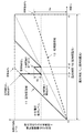
例えば特許文献1(特開2008−99158号公報)は、複数の異なる露光量の画像を合成して広いダイナミックレンジの画像を得る構成を開示している。図1を参照して、この処理について説明する。撮像デバイスは、例えば、動画撮影においては、ビデオレート(30−60fps)内に2つの異なる露光時間の画像データを出力する。また、静止画撮影においても、2つの異なる露光時間の画像データを生成して出力する。図1は、撮像デバイスが生成する2つの異なる露光時間を持つ画像(長時間露光画像と、短時間露光画像)の特性について説明する図である。横軸は時間(t)であり、縦軸は固体撮像素子の1つの画素に対応する光電変換素子を構成する受光フォトダイオード(PD)における蓄積電荷量(e)である。 For example, Patent Document 1 (Japanese Patent Laid-Open No. 2008-99158) discloses a configuration in which an image having a wide dynamic range is obtained by combining a plurality of images having different exposure amounts. This process will be described with reference to FIG. For example, in moving image shooting, the imaging device outputs image data of two different exposure times within a video rate (30-60 fps). In still image shooting, image data with two different exposure times are generated and output. FIG. 1 is a diagram illustrating the characteristics of an image (long exposure image and short exposure image) having two different exposure times generated by the imaging device. The horizontal axis represents time (t), and the vertical axis represents the accumulated charge amount (e) in the light receiving photodiode (PD) constituting the photoelectric conversion element corresponding to one pixel of the solid-state imaging element.
例えば、受光フォトダイオード(PD)の受光量が多い、すなわち明るい被写体に対応する場合、図1に示す高輝度領域11に示すように、時間経過に伴う電荷蓄積量は急激に上昇する。一方、受光フォトダイオード(PD)の受光量が少ない、すなわち暗い被写体に対応する場合、図1に示す低輝度領域12に示すように、時間経過に伴う電荷蓄積量は緩やかに上昇する。 For example, when the amount of light received by the light receiving photodiode (PD) is large, that is, when the subject corresponds to a bright subject, as shown in the high luminance region 11 shown in FIG. On the other hand, when the amount of light received by the light-receiving photodiode (PD) is small, that is, when the object corresponds to a dark subject, the charge accumulation amount gradually increases as time passes, as shown in the low luminance region 12 shown in FIG.
時間t0〜t3が長時間露光画像を取得するための露光時間TLに相当する。この長時間の露光時間TLとしても低輝度領域12に示すラインは、時間t3において電荷蓄積量は飽和レベルに達することなく(非飽和点Py)、この電荷蓄積量(Sa)に基づいて得られる電気信号を利用して決定する画素の階調レベルにより、正確な階調表現を得ることができる。 Time t0 to t3 corresponds to an exposure time TL for acquiring a long-time exposure image. Even when the long exposure time TL is shown, the line shown in the low luminance region 12 is obtained based on the charge accumulation amount (Sa) without the charge accumulation amount reaching the saturation level at the time t3 (unsaturated point Py). An accurate gradation expression can be obtained by the gradation level of the pixel determined using the electric signal.
しかし、高輝度領域11に示すラインは、時間t3に至る以前に、すでに電荷蓄積量は飽和レベル(飽和点Px)に達することが明らかである。従って、このような高輝度領域11は、長時間露光画像からは飽和レベルの電気信号に対応する画素値しか得られず、結果として白とび画素になってしまう。 However, it is apparent that the charge accumulation amount of the line shown in the high luminance region 11 has already reached the saturation level (saturation point Px) before reaching the time t3. Therefore, in such a high brightness area 11, only a pixel value corresponding to the electrical signal of the saturation level can be obtained from the long-time exposure image, and as a result, the overexposed pixel is obtained.
そこで、このような高輝度領域11では、時間t3に至る前の時間、例えば図に示す時間t1(電荷掃き出し開始点P1)において、一旦、受光フォトダイオード(PD)の蓄積電荷を掃き出す。電荷掃き出しは、受光フォトダイオード(PD)に蓄積された全ての電荷ではなく、フォトダイオード(PD)において制御される中間電圧保持レベルまでとする。この電荷掃き出し処理の後、再度、露光時間TS(t2〜t3)とした短時間露光を実行する。すなわち、図に示す短時間露光開始点P2〜短時間露光終了点P3までの期間の短時間露光を行なう。この短時間露光によって電荷蓄積量(Sb)が得られ、この電荷蓄積量(Sb)に基づいて得られる電気信号に基づいて、画素の階調レベルを決定する。 Therefore, in such a high luminance region 11, the accumulated charge of the light receiving photodiode (PD) is once swept out at a time before reaching the time t3, for example, at a time t1 (charge sweep start point P1) shown in the drawing. The charge sweeping is performed not to all charges accumulated in the light receiving photodiode (PD) but to an intermediate voltage holding level controlled in the photodiode (PD). After this charge sweeping process, short-time exposure with exposure time TS (t2 to t3) is performed again. That is, short-time exposure is performed for a period from the short-time exposure start point P2 to the short-time exposure end point P3 shown in the drawing. A charge accumulation amount (Sb) is obtained by this short-time exposure, and a gradation level of the pixel is determined based on an electric signal obtained based on the charge accumulation amount (Sb).
なお、低輝度領域12における長時間露光によって得られる電荷蓄積量(Sa)に基づく電気信号と、高輝度領域251における短時間露光によって得られる電荷蓄積量(Sb)に基づく電気信号とに基づいて画素値を決定する際は、同一時間露光を行なった場合の推定電荷蓄積量またはその推定電荷蓄積量に対応する電気信号出力値を算出して、算出した結果に基づいて画素値レベルを決定する。 In addition, based on the electric signal based on the charge accumulation amount (Sa) obtained by the long-time exposure in the low luminance region 12 and the electric signal based on the charge accumulation amount (Sb) obtained by the short-time exposure in the high luminance region 251. When determining a pixel value, an estimated charge accumulation amount when exposure is performed for the same time or an electric signal output value corresponding to the estimated charge accumulation amount is calculated, and a pixel value level is determined based on the calculated result. .
このように、短時間露光画像と長時間露光画像を組み合わせることで、白とびのないダイナミックレンジの広い画像を得ることができる。 As described above, by combining the short-time exposure image and the long-time exposure image, an image having a wide dynamic range without overexposure can be obtained.
しかし、このような異なる露光量の複数画像は、時間的に異なるタイミングで撮影した画像となる。従って、その間に被写体の動きが発生すると、画像の合成時に画像のずれが発生する。この結果、動く被写体領域の画像部分に偽色が発生し、画像の品質が低下する等の問題を生じさせることになる。 However, such a plurality of images with different exposure amounts are images taken at different timings. Therefore, if the movement of the subject occurs during that time, an image shift occurs when the images are combined. As a result, a false color is generated in the image portion of the moving subject area, which causes problems such as deterioration in image quality.
このような問題を低減させる技術を開示した従来技術として、例えば特許文献2(特開2000−50151号公報)がある。
特許文献2(特開2000−50151号公報)は、異なる露光量の複数画像を比較して動きのあった画素領域を特定して補正を行う構成を開示している。具体的な処理は以下の通りである。まず、長時間露光画像(LE)と短時間露光画像(SE)を取得し、長時間露光画像(LE)と短時間露光画像(SE)の露光量の比である露光比A(=LE/SE)を求める。さらに各画素について、(LE−SE×A)を算出する。全く同じ被写体を撮影している場合、(LE−SE×A)=0となるはずである。(LE−SE×A)=0とならない画素は、長時間露光画像(LE)と短時間露光画像(SE)とで異なる被写体を撮影している可能性が高く、このような画素領域を動き領域として識別する構成である。
As a prior art disclosing a technique for reducing such a problem, there is, for example, Japanese Patent Application Laid-Open No. 2000-50151.
Patent Document 2 (Japanese Patent Laid-Open No. 2000-50151) discloses a configuration in which a plurality of images with different exposure amounts are compared to identify a pixel region that has moved and perform correction. Specific processing is as follows. First, a long exposure image (LE) and a short exposure image (SE) are acquired, and an exposure ratio A (= LE /) which is a ratio of exposure amounts of the long exposure image (LE) and the short exposure image (SE). SE). Further, (LE−SE × A) is calculated for each pixel. If the same subject is being photographed, (LE-SE × A) = 0 should be obtained. It is highly likely that pixels that do not have (LE-SE × A) = 0 are shooting different subjects in the long-exposure image (LE) and the short-exposure image (SE). It is the structure identified as an area | region.
すなわち、同一の被写体が撮影されている場合、長時間露光画像(LE)の出力値(輝度)と、短時間露光画像(SE)の出力値(輝度)との対応関係は、図2に示すような傾きA(=露光比)のライン上に設定されることになり、このラインからずれている場合は、動きの発生した領域であると判断するものである。 That is, when the same subject is photographed, the correspondence between the output value (luminance) of the long exposure image (LE) and the output value (luminance) of the short exposure image (SE) is shown in FIG. It is set on a line having such an inclination A (= exposure ratio), and if it is deviated from this line, it is determined that the region has moved.
しかしながら、現実的には、撮像素子を構成するPDやトランジスタの特製にはばらつきがあり、(LE−SE×A)=0を満足するか否かによって被写体の動きの有無を正確に判別することは困難である。例えば、閾値(Th)を設定して、|LE−SE×A|<Thを満足するか否かによって判別すれば、多少の素子のばらつきを吸収できるが、素子のばらつきは各装置によっても異なり、最適な閾値を設定することが難しいという問題がある。 However, in reality, there are variations in the special characteristics of PDs and transistors constituting the imaging device, and it is possible to accurately determine the presence or absence of movement of the subject depending on whether or not (LE-SE × A) = 0 is satisfied. It is difficult. For example, if a threshold value (Th) is set and it is determined whether or not | LE−SE × A | <Th is satisfied, some element variations can be absorbed, but the element variations vary depending on each device. There is a problem that it is difficult to set an optimum threshold value.
本発明は、例えば、上述の問題点に鑑みてなされたものであり、露光時間の異なる複数の画像を合成してダイナミックレンジの広い画像を生成する際に、偽色発生など画質を低下させる恐れのある被写体の動きが発生した領域を正確に判別可能とした画像処理装置、撮像装置、および画像処理方法、並びにプログラムを提供することを目的とする。 The present invention has been made in view of the above-described problems, for example, and may reduce image quality such as generation of false colors when a plurality of images having different exposure times are combined to generate an image with a wide dynamic range. An object of the present invention is to provide an image processing apparatus, an imaging apparatus, an image processing method, and a program capable of accurately discriminating a region where a certain subject motion occurs.
本発明の第1の側面は、
異なる露光時間の撮影画像を合成して合成画像を生成する画像合成部と、
前記画像合成部の生成した複数の合成画像の比較処理を行い、画素値差分を取得して、該画素値差分と予め設定した閾値との比較を行い、画素値差分が閾値以上である画素領域を被写体の動きが発生したと推測される動き領域であると判定する動き領域検出処理を実行する動き領域検出部と、
を有する画像処理装置にある。
The first aspect of the present invention is:
An image composition unit that synthesizes captured images with different exposure times to generate a composite image;
A pixel region in which a plurality of composite images generated by the image composition unit are compared, a pixel value difference is acquired, the pixel value difference is compared with a preset threshold value, and the pixel value difference is equal to or greater than the threshold value A motion region detection unit that executes a motion region detection process that determines that a motion region is estimated to have occurred,
In an image processing apparatus.
さらに、本発明の画像処理装置の一実施態様において、前記画像合成部は、異なる露光時間の撮影画像を1枚入力する毎に、新規入力画像と、入力済みの異なる露光時間の撮影画像を組み合わせて合成画像を生成する構成であり、前記動き領域検出部は、前記画像合成部の生成する連続する2つの合成画像の対応画素の画素値を比較して動き領域検出処理を実行する。 Furthermore, in one embodiment of the image processing apparatus of the present invention, the image composition unit combines a new input image and a captured image with a different exposure time each time one captured image with a different exposure time is input. The motion region detection unit compares the pixel values of corresponding pixels of two consecutive composite images generated by the image synthesis unit and executes a motion region detection process.
さらに、本発明の画像処理装置の一実施態様において、前記画像処理装置は、さらに、前記合成画像の生成元である被合成画像間の対応画素の出力値を比較し、被合成画像画素値差分を取得する合成前画像比較部と、前記動き領域検出部が検出した動き領域の対応画素について、前記被合成画像画素値差分と予め設定した第2閾値との比較を行い、前記被合成画像画素値差分が第2閾値未満である画素領域を動き領域には該当しないと判定する過検出除去部を有する。 Furthermore, in one embodiment of the image processing device of the present invention, the image processing device further compares output values of corresponding pixels between the synthesized images that are the generation source of the synthesized image, and compares the synthesized image pixel value difference. For the corresponding pixel of the motion region detected by the pre-combine image comparison unit and the motion region detection unit, the composite image pixel value difference is compared with a preset second threshold value, and the composite image pixel An overdetection removal unit that determines that a pixel area whose value difference is less than the second threshold value does not correspond to a motion area is included.
さらに、本発明の画像処理装置の一実施態様において、前記画像処理装置は、さらに、前記合成画像の生成元である被合成画像の画素対応選択情報を利用して、合成画像上の隣接画素に異なる露光時間の撮影画像の画素が設定された画素領域を画質劣化領域であると判定し、前記動き領域検出部の検出した動き領域であり、かつ前記画質劣化領域である画素領域を画質劣化動き領域として抽出した画質劣化動き領域検出情報を出力する画質劣化領域検出部を有する。 Furthermore, in one embodiment of the image processing apparatus of the present invention, the image processing apparatus further uses the pixel correspondence selection information of the composite image that is the generation source of the composite image to determine adjacent pixels on the composite image. It is determined that a pixel area in which pixels of captured images having different exposure times are set is an image quality degradation area, and the pixel area that is the motion area detected by the motion area detector and is the image quality degradation area It has an image quality degradation area detection unit that outputs image quality degradation motion area detection information extracted as an area.
さらに、本発明の画像処理装置の一実施態様において、前記画像処理装置は、さらに、前記合成画像の生成元である被合成画像の画素対応選択情報を利用して、合成画像の各画素について被合成画像の画素値を取得し、被合成画像の画素値が0近傍または飽和値近傍にある場合、この画素領域を出力値の有効性が低いと判定する出力値有効領域検出部と、前記出力値有効領域検出部の検出した出力値の有効性が低い画素領域を画質劣化の可能性の高い画質劣化領域であると判断し、前記動き領域検出部の検出した動き領域であり、かつ前記画質劣化領域である画素領域を画質劣化動き領域として抽出した画質劣化動き領域検出情報を出力する画質劣化領域検出部を有する。 Furthermore, in an embodiment of the image processing apparatus of the present invention, the image processing apparatus further uses the pixel correspondence selection information of the composite image that is the generation source of the composite image to cover each pixel of the composite image. An output value effective region detection unit that obtains a pixel value of a composite image and determines that the effectiveness of the output value of the pixel region is low when the pixel value of the composite image is near 0 or a saturation value; It is determined that a pixel area whose output value detected by the value effective area detection unit is less effective is an image quality deterioration area having a high possibility of image quality deterioration, is a motion area detected by the motion area detection unit, and the image quality It has an image quality degradation area detection unit that outputs image quality degradation motion area detection information obtained by extracting a pixel area as a degradation area as an image quality degradation motion area.
さらに、本発明の画像処理装置の一実施態様において、前記画像処理装置は、さらに、前記合成画像の生成元である被合成画像の画素対応選択情報を利用して、合成画像に利用された画素が長時間露光画像の画素であり、かつ当該画素に対応する短時間露光画像の画素値が0近傍にない有効画素値を有する画素を動き領域であると判定する第2動き領域検出部を有し、前記動き領域検出部が動き領域であると判定し、かつ前記第2動き領域検出部が動き領域として判定した領域を最終的な動き領域とした動き領域検出情報を出力する検出結果統合部を有する。 Furthermore, in an embodiment of the image processing device of the present invention, the image processing device further uses the pixel correspondence selection information of the composite image that is the generation source of the composite image, and uses the pixel used in the composite image. Has a second motion area detection unit that determines that a pixel having a valid pixel value that is a pixel of a long exposure image and whose pixel value of the short exposure image corresponding to the pixel is not near 0 is a motion area. And a detection result integrating unit that outputs motion region detection information in which the motion region detection unit determines that the motion region is a motion region and the second motion region detection unit determines the motion region as a final motion region. Have
さらに、本発明の第2の側面は、
異なる露光時間の撮影画像を合成して合成画像を生成する画像合成部と、
前記合成画像の生成元である被合成画像の画素対応選択情報を利用して、合成画像の各画素について被合成画像の画素値を取得し、被合成画像の画素値が0近傍または飽和値近傍にある場合、この画素領域を出力値の有効性が低いと判定し、該領域を画質劣化の可能性の高い画質劣化領域として明示した画質劣化領域検出情報を出力する出力値有効領域検出部を有する画像処理装置にある。
Furthermore, the second aspect of the present invention provides
An image composition unit that synthesizes captured images with different exposure times to generate a composite image;
Using the pixel correspondence selection information of the composite image that is the generation source of the composite image, the pixel value of the composite image is obtained for each pixel of the composite image, and the pixel value of the composite image is near 0 or near the saturation value An output value effective area detection unit that determines that the output value of the pixel area is low and outputs the image quality degradation area detection information that clearly indicates the area as an image quality degradation area that has a high possibility of image quality degradation. It is in the image processing apparatus having.
さらに、本発明の第3の側面は、
異なる露光時間の撮影画像を合成して合成画像を生成する画像合成部と、
前記合成画像の生成元である被合成画像の画素対応選択情報を利用して、合成画像に利用された画素が長時間露光画像の画素であり、かつ当該画素に対応する短時間露光画像の画素値が0近傍にない有効画素値を有する画素を動き領域であると判定し、動き領域を明示した動き領域検出情報を出力する動き領域検出部を有する画像処理装置にある。。
Furthermore, the third aspect of the present invention provides
An image composition unit that synthesizes captured images with different exposure times to generate a composite image;
Using the pixel correspondence selection information of the synthesized image that is the generation source of the synthesized image, the pixel used in the synthesized image is a pixel of the long-time exposure image, and the pixel of the short-time exposure image corresponding to the pixel The image processing apparatus includes a motion region detection unit that determines that a pixel having an effective pixel value that is not in the vicinity of 0 is a motion region, and outputs motion region detection information that clearly indicates the motion region. .
さらに、本発明のが第4の側面は、
異なる露光時間の撮影画像の対応画素の画素値差分と、予め規定した相関情報との差分を算出し、該差分が予め規定した閾値より大きい場合に動き領域であると判定する検出部を有する画像処理装置にある。
Furthermore, the fourth aspect of the present invention is
An image having a detection unit that calculates a difference between a pixel value difference of a corresponding pixel of a captured image having a different exposure time and a predetermined correlation information, and determines that it is a motion region when the difference is larger than a predetermined threshold value. In the processing unit.
さらに、本発明の画像処理装置の一実施態様において、前記相関情報は、比較対象とする異なる露光時間の画像の出力値の相関に基づいて作成された相関情報である。 Furthermore, in one embodiment of the image processing apparatus of the present invention, the correlation information is correlation information created based on a correlation between output values of images having different exposure times to be compared.
さらに、本発明の第5の側面は、
前記画像処理装置は、さらに、
異なる露光時間の撮影画像を撮影する撮像デバイスと、
請求項1〜10いずれかに記載の画像処理を実行する画像処理部を有する撮像装置にある。
Furthermore, the fifth aspect of the present invention provides
The image processing apparatus further includes:
An imaging device for taking images of different exposure times;
It exists in the imaging device which has an image processing part which performs the image processing in any one of Claims 1-10.
さらに、本発明の第6の側面は、
画像処理装置において実行する画像処理方法であり、
画像合成部が、異なる露光時間の撮影画像を合成して合成画像を生成する画像合成ステップと、
動き領域検出部が、前記画像合成部の生成した複数の合成画像の比較処理を行い、画素値差分を取得して、該画素値差分と予め設定した閾値との比較を行い、画素値差分が閾値以上である画素領域を被写体の動きが発生したと推測される動き領域であると判定する動き領域検出処理を実行する動き領域検出ステップと、
を有する画像処理方法にある。
Furthermore, the sixth aspect of the present invention provides
An image processing method executed in an image processing apparatus,
An image compositing unit for compositing captured images with different exposure times to generate a composite image; and
The motion region detection unit performs a comparison process of a plurality of synthesized images generated by the image synthesis unit, acquires a pixel value difference, compares the pixel value difference with a preset threshold value, and the pixel value difference is A motion region detection step for executing a motion region detection process for determining that a pixel region that is equal to or greater than a threshold is a motion region in which motion of the subject is estimated to have occurred;
An image processing method having
さらに、本発明の第7の側面は、
画像処理装置において画像処理を実行させるプログラムであり、
画像合成部に、異なる露光時間の撮影画像を合成して合成画像を生成させる画像合成ステップと、
動き領域検出部に、前記画像合成部の生成した複数の合成画像の比較処理を行い、画素値差分を取得して、該画素値差分と予め設定した閾値との比較を行い、画素値差分が閾値以上である画素領域を被写体の動きが発生したと推測される動き領域であると判定する動き領域検出処理を実行させる動き領域検出ステップと、
を有するプログラムにある。
Furthermore, the seventh aspect of the present invention provides
A program for executing image processing in an image processing apparatus;
An image synthesis step for causing the image synthesis unit to synthesize the captured images having different exposure times to generate a synthesized image;
The motion region detection unit performs a comparison process of a plurality of synthesized images generated by the image synthesis unit, acquires a pixel value difference, compares the pixel value difference with a preset threshold value, and the pixel value difference is A motion region detection step for executing a motion region detection process for determining that a pixel region that is equal to or greater than the threshold is a motion region in which motion of the subject is estimated to have occurred,
Is in a program with
なお、本発明のプログラムは、例えば、様々なプログラム・コードを実行可能な情報処理装置やコンピュータ・システムに対して、コンピュータ可読な形式で提供する記憶媒体、通信媒体によって提供可能なプログラムである。このようなプログラムをコンピュータ可読な形式で提供することにより、情報処理装置やコンピュータ・システム上でプログラムに応じた処理が実現される。 The program of the present invention is, for example, a program that can be provided by a storage medium or a communication medium provided in a computer-readable format to an information processing apparatus or a computer system that can execute various program codes. By providing such a program in a computer-readable format, processing corresponding to the program is realized on the information processing apparatus or the computer system.
本発明のさらに他の目的、特徴や利点は、後述する本発明の実施例や添付する図面に基づくより詳細な説明によって明らかになるであろう。なお、本明細書においてシステムとは、複数の装置の論理的集合構成であり、各構成の装置が同一筐体内にあるものには限らない。 Other objects, features, and advantages of the present invention will become apparent from a more detailed description based on embodiments of the present invention described later and the accompanying drawings. In this specification, the system is a logical set configuration of a plurality of devices, and is not limited to one in which the devices of each configuration are in the same casing.
本発明の一実施例の構成によれば、異なる露光時間の複数の画像を入力して、それぞれの有効な画素値を選択的に組み合わせた広ダイナミックレンジ画像を生成する処理において、偽色等、画質劣化の発生要因となる被写体の動き領域を効率的に検出することが可能となる。例えば、異なる露光時間の複数の画像により生成した合成画像の比較を実行して、その比較結果に基づいて動き領域を検出する。この処理によれば撮像素子の特性のばらつきによる誤検出を抑制した精度の高い動き領域検出を行うことが可能となる。 According to the configuration of an embodiment of the present invention, in a process of inputting a plurality of images having different exposure times and generating a wide dynamic range image in which each effective pixel value is selectively combined, false colors, etc. It is possible to efficiently detect a moving area of a subject that causes image quality degradation. For example, a comparison of composite images generated by a plurality of images having different exposure times is executed, and a motion region is detected based on the comparison result. According to this processing, it is possible to perform highly accurate motion region detection that suppresses erroneous detection due to variations in characteristics of the image sensor.
以下、図面を参照しながら、本発明の画像処理装置、撮像装置、および画像処理方法、並びにプログラムについて説明する。説明は以下の項目順に行う。
1.画像処理装置の全体構成例について
2.画像処理装置の具体的実施例
Hereinafter, an image processing apparatus, an imaging apparatus, an image processing method, and a program according to the present invention will be described with reference to the drawings. The description will be given in the following order.
1. 1. Example of overall configuration of image processing apparatus Specific example of image processing apparatus
[1.画像処理装置の全体構成例について]
まず、本発明の画像処理装置の全体構成例について図3を参照して説明する。
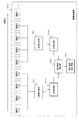
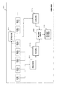
図3は、本発明の画像処理装置の一例である撮像装置の構成例を示すブロック図である。光学レンズ101を通して入射される光は例えばCMOSイメージセンサなどによって構成される撮像デバイス102に入射し、光電変換による画像データを出力する。出力画像データはメモリ103を介して画像処理部104に入力される。制御部105は、例えば図示しないメモリに格納されたプログラムに従って各部に制御信号を出力し、各種の処理制御を行う。
[1. Example of overall configuration of image processing apparatus]
First, an example of the overall configuration of the image processing apparatus of the present invention will be described with reference to FIG.
FIG. 3 is a block diagram illustrating a configuration example of an imaging apparatus which is an example of the image processing apparatus of the present invention. The light incident through the
撮像デバイス102は、異なる露光時間の複数の画像111〜114を生成する。画像処理部104は、これら異なる露光時間の複数の画像111〜114を入力して合成処理を行い、出力画像120を生成する。以下に説明する実施例では、画像処理部104は、4種類の異なる露光時間の画像を撮像デバイス102から入力するものとして説明する。すなわち、図3に示すように、
画像1(露光時間T1)111
画像2(露光時間T2)112
画像3(露光時間T3)113
画像4(露光時間T4)114
ただし、T1<T2<T3<T4
画像処理部104は、これらの4種類の異なる露光時間(T1〜T4)の画像を撮像素子102から入力し、これらの異なる露光時間の複数の画像に基づいて出力画像120を生成する。
The
Image 1 (exposure time T1) 111
Image 2 (exposure time T2) 112
Image 3 (exposure time T3) 113
Image 4 (exposure time T4) 114
However, T1 <T2 <T3 <T4
The
前述したように撮像デバイスの出力する電気信号は、撮像デバイスに対する入射光量に応じたものとなる。従って、一定の露光時間(長時間露光)とした場合、より明るい被写体に対応する画素の光電変換素子の出力する電気信号が飽和レベルに達してしまう場合がある。結果として、これらの画素については、飽和レベルの電気信号が出力され、諧調差が認識できない、いわゆる白とび画素となってしまう。 As described above, the electrical signal output from the imaging device is in accordance with the amount of light incident on the imaging device. Therefore, when the exposure time is constant (long exposure), the electrical signal output from the photoelectric conversion element of the pixel corresponding to a brighter subject may reach a saturation level. As a result, for these pixels, an electrical signal of a saturation level is output, and so-called overexposed pixels in which the gradation difference cannot be recognized.
例えばこのような白とびを防止し、被写体の輝度レベルを反映した出力を得るため、長時間露光〜短時間露光の複数の画像データを生成し、画像処理部104において、これら複数の画像の合成処理を実行して出力画像120を得る。例えば、長時間露光を行なった場合に飽和レベルに至ると推測される画素については、短時間露光を行なったデータに基づいて計算した画素値を出力するという処理などを行なうものである。
For example, in order to prevent such overexposure and obtain an output reflecting the luminance level of the subject, a plurality of image data of long exposure to short exposure is generated, and the
複数の異なる露光時間の画像の取得処理については、本出願人と同一出願人による特許出願である特開2008−99158公報、あるいは、特開2008−227697号公報に記載されており、基本的には、これらに記載された構成と同様の方法で複数の異なる露光時間の画像を取得し白とび画素の発生しない合成画像を生成する。なお、これらの特許公開公報には長時間露光画像と短時間露光画像の2種類の画像の取得処理について記載しているが、本発明では、例えば4種類の異なる露光時間の画像を取得して処理を行う。 The acquisition processing of images having a plurality of different exposure times is described in Japanese Patent Application Laid-Open No. 2008-99158 or Japanese Patent Application Laid-Open No. 2008-227697, which is a patent application filed by the same applicant as the present applicant. Obtains a plurality of images having different exposure times by a method similar to the configuration described above, and generates a composite image in which no overexposed pixels occur. Note that these patent publications describe the acquisition processing of two types of images, a long exposure image and a short exposure image, but in the present invention, for example, four types of images with different exposure times are acquired. Process.
前述したように、異なる露光量の複数画像は、時間的に異なるタイミングで撮影した画像となる。従って、その間に被写体の動きが発生すると画像の合成時に画像のずれが発生する。この結果、動く被写体領域の画像領域に偽色が発生し、画像の品質が低下する等の問題を生じさせることになる。 As described above, a plurality of images with different exposure amounts are images taken at different timings. Accordingly, if the movement of the subject occurs during that time, an image shift occurs when the images are combined. As a result, a false color is generated in the image area of the moving subject area, which causes problems such as a reduction in image quality.
画像処理部104は、撮像デバイス102から入力する画像の合成処理を行う前に、被写体の動きが発生したと推定される画像領域を判別する処理を行う。この動き判別処理によって動き領域と判定された画素領域については補正処理を行った上で合成画像を生成する。以下では、複数の異なる露光時間の画像を適用した動き画像領域の検出処理の具体的な実施例について説明する。
The
[2.画像処理装置の具体的実施例]
以下、図3に示す画像処理装置の構成および処理の具体的な複数の実施例について説明する。
[2. Specific Example of Image Processing Device]
A specific example of the configuration and processing of the image processing apparatus shown in FIG. 3 will be described below.
(2−1)実施例1
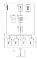
図4は、本発明の実施例1に係る画像処理装置の画像処理部104の処理を中心ととして説明する図である。上部に示す時間軸(t)に従って左から右方向に時間が経過して処理が進行する。すなわち、時間経過に伴い、露光時間(T1)の画像1、露光時間(T2)の画像2、露光時間(T3)の画像3、露光時間(T4)の画像4・・・これらの画像が順次入力されて処理が行われる。
(2-1) Example 1
FIG. 4 is a diagram for explaining mainly the processing of the
画像処理部104は、撮像デバイス102の取得した露光時間(T1)の画像1、露光時間(T2)の画像2、露光時間(T3)の画像3、露光時間(T4)の画像4の4つの異なる露光時間の画像を順次入力する。その後、同様に、露光時間(T1)の画像5、露光時間(T2)の画像6、露光時間(T3)の画像7、露光時間(T4)の画像8の4つの異なる露光時間の画像を順次入力する。以下、この繰り返しとなる。なお、露光時間T1〜T4は、T1<T2<T3<T4である。
The
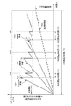
画像処理部104は、必要に応じてこれら露光時間T1〜T4の4枚の画像を利用して、1枚の広ダイナミックレンジ画像を合成する。合成処理の一例について、図5を参照して説明する。図5は、先に図1を参照して説明した長時間露光画像と短時間露光画像の2つの画像取得および合成処理と基本的には同様であり、露光時間を4種類に増加させている点が異なる。
The
図5において、横軸は時間(t)であり、縦軸は撮像デバイス102を構成する固体撮像素子の1つの画素に対応する光電変換素子を構成する受光フォトダイオード(PD)における蓄積電荷量(e)である。例えば、受光フォトダイオード(PD)の受光量が多い、すなわち明るい被写体に対応する場合、図5に示す超高輝度領域151に示すように、時間経過に伴う電荷蓄積量は急激に上昇する。一方、受光フォトダイオード(PD)の受光量が少ない、すなわち暗い被写体に対応する場合、図5に示す低輝度領域154に示すように、時間経過に伴う電荷蓄積量は緩やかに上昇する。高輝度領域152、中輝度領域153はその間の明るさの被写体である。すなわち、被写体の明るさの順番は、以下の通りとなる。
超高輝度領域151>高輝度領域152>中輝度領域153>低輝度領域154
In FIG. 5, the horizontal axis represents time (t), and the vertical axis represents the amount of charge accumulated in the light receiving photodiode (PD) constituting the photoelectric conversion element corresponding to one pixel of the solid-state imaging element constituting the imaging device 102 ( e). For example, when the amount of light received by the light receiving photodiode (PD) is large, that is, when the subject corresponds to a bright subject, the charge accumulation amount with time elapses rapidly as shown in the
Super
低輝度領域154の画素は、最長の露光時間(T4)の露光を行っても電荷蓄積量は飽和レベルに達することない。従って、露光時間(T4)経過後の電荷蓄積量に基づいて得られる図の右短に示す[長時間露光出力]信号を利用して決定する画素の階調レベルにより、正確な階調表現を得ることができる。
Even if the pixel in the
しかし、超高輝度領域151、高輝度領域152、中輝度領域153に示すラインは、最長露光時間(T4)に至る以前に、すでに電荷蓄積量は飽和レベルに達する可能性が高い。従って、このような画素領域は、長時間露光画像からは飽和レベルの電気信号に対応する画素値しか得られず、結果として白とび画素になってしまう。
However, in the lines shown in the
そこで、このような超高輝度〜中輝度領域151〜153に対応する画素では、それぞれ予め設定したタイミング(tp1,tq1,tr1)で、一旦、受光フォトダイオード(PD)の蓄積電荷を掃き出す。電荷掃き出しは、受光フォトダイオード(PD)に蓄積された全ての電荷ではなく、フォトダイオード(PD)において制御される中間電圧保持レベルまでとする。この電荷掃き出し処理の後、再度、露光時間(T1=tp1〜tp2)、露光時間(T2=tq1〜tq2)、露光時間(T3=tr1〜tr2)とした露光処理を実行する。すなわち、図に示すように、短時間露光時間(T1)、短時間露光時間(T2)、短時間露光時間(T3)、これらの短時間露光を行なう。
Therefore, in the pixels corresponding to such ultra-high luminance to
このように複数の異なる露光時間T1〜T4(T1<T2<T3<T4)によって、それぞれの露光時間に対応する電荷蓄積量が得られ、この電荷蓄積量に基づいて得られる電気信号に基づいて、画素の階調レベルを決定する。なお、各露光時間によって得られる電荷蓄積量に基づく電気信号に基づいて画素値を決定する際は、同一時間露光を行なった場合の推定電荷蓄積量またはその推定電荷蓄積量に対応する電気信号出力値を算出して、算出した結果に基づいて画素値レベルを決定する。このように、短時間露光画像と長時間露光画像を組み合わせることで、白とびのないダイナミックレンジの広い画像を得ることができる。 As described above, a plurality of different exposure times T1 to T4 (T1 <T2 <T3 <T4) provide a charge accumulation amount corresponding to each exposure time, and based on an electric signal obtained based on the charge accumulation amount. The gradation level of the pixel is determined. When determining the pixel value based on the electric signal based on the charge accumulation amount obtained by each exposure time, the electric signal output corresponding to the estimated charge accumulation amount when the same time exposure is performed or the estimated charge accumulation amount A value is calculated, and a pixel value level is determined based on the calculated result. As described above, by combining the short-time exposure image and the long-time exposure image, an image having a wide dynamic range without overexposure can be obtained.
なお、露光時間T1〜T4は、例えば、T4=1/30sec、T3=1/300sec、T2=1/3000sec、T1=1/30000secなどの設定が可能である。例えばT1〜T4をこの設定とし、図3に示す出力画像120を露光時間T1〜T4の4つの画像の合成画像として生成すると、出力画像120が動画像である場合には、30fpsに相当する動画を順次生成することができる。
これは、T4=1/30sec毎に、超高輝度画素=露光時間T1の露光画像〜低輝度画素=露光時間T4の露光画像これらの各画像に基づく合成画像を生成することができるからである。
The exposure times T1 to T4 can be set, for example, T4 = 1/30 sec, T3 = 1/300 sec, T2 = 1/3000 sec, T1 = 1/30000 sec. For example, when T1 to T4 are set as described above and the
This is because, every T4 = 1/30 sec, a super high brightness pixel = exposure image with exposure time T1 to low brightness pixel = exposure image with exposure time T4. A composite image based on these images can be generated. .
しかし、露光時間T1〜T4とした複数の露光量の異なる画像は、時間的に異なるタイミングで撮影した画像となる。従って、その間に被写体の動きが発生すると、画像の合成時に画像のずれが発生する。この結果、動く被写体領域の画像部分に偽色が発生し、画像の品質が低下する等の問題を生じさせることになる。 However, a plurality of images having different exposure amounts with exposure times T1 to T4 are images taken at different timings. Therefore, if the movement of the subject occurs during that time, an image shift occurs when the images are combined. As a result, a false color is generated in the image portion of the moving subject area, which causes problems such as deterioration in image quality.
本発明の画像処理装置100の画像処理部104は、この問題を解決するため、動く被写体の画像領域を識別する。なお、以下では、
動く被写体を「動被写体」、
動く被写体の撮影画像領域を「動き領域」、
と呼ぶ。
本実施例の画像処理部104は、図4に示すように、複数の合成後の画像を用いて動き領域を識別する。
In order to solve this problem, the
A moving subject is called a “moving subject”,
The moving image area of the moving subject
Call it.
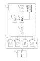
As illustrated in FIG. 4, the
図4に示すように、画像処理部104は、画像合成部201、動き領域検出部202を有する。なお、図4には画像合成部201を2つ示しているが、これは、画像1〜4の合成処理を先行して実行し、その後、画像5〜8の合成処理を実行することを示すものであり、1つの画像合成部201がシーケンシャルに処理を行うことを示しているものである。すなわち、複数の画像合成部は必要でなく1つの画像合成部201があればよい。
As illustrated in FIG. 4, the
動き領域検出部202は、画像合成部201の生成した2つの合成画像を比較して動き領域を判別する。すなわち、
画像1〜4の合成処理により生成した合成画像a,141a、
画像5〜8の合成処理により生成した合成画像b,141b、
このように連続して生成した2つの合成画像を比較して画像に含まれる動き領域を検出する。この検出結果を動き領域検出情報143として出力する。
The motion
Composite images a and 141a generated by the composite processing of the
Combined images b and 141b generated by combining the images 5 to 8;
Two synthesized images generated in this way are compared to detect a motion region included in the image. This detection result is output as motion
動き領域検出部202は、合成後の画像同士の画素値を比較する。被写体が動かない場合、同一座標の画素値は一致する。すなわち合成画像a,141aのある座標の高輝度画素は、合成画像b,141bの対応座標位置でも同じ高輝度画素であり、合成画像a,141aの低輝度画素は、合成画像b,141bにおいても同じ低輝度画素となる。この画素値の対応関係を示したのが図6である。
The motion
図6は、横軸が現在の合成画像(合成画像b,141b)の画素値(0〜MAX)、縦軸が過去の合成画像(合成画像a,141a)の画素値(0〜MAX)を示す。例えば、現在の合成画像(合成画像b,141b)のある座標(x1,y1)の画素値がp1である場合、過去の合成画像(合成画像a,141a)の同じ座標の画素値もp1となるはずである。すなわち、被写体が動かない場合、同一座標の画素値は一致し、図に示す傾きが1の直線上にのるはずである。 In FIG. 6, the horizontal axis represents the pixel value (0-MAX) of the current composite image (composite image b, 141b), and the vertical axis represents the pixel value (0-MAX) of the past composite image (composite image a, 141a). Show. For example, if the pixel value of a coordinate (x1, y1) of the current composite image (composite image b, 141b) is p1, the pixel value of the same coordinate of the past composite image (composite image a, 141a) is also p1. Should be. That is, when the subject does not move, the pixel values of the same coordinates are the same, and the inclination shown in the figure should be on a straight line of 1.
なお、図6に示すように、現在の合成画像(合成画像b,141b)と、過去の合成画像(合成画像a,141a)のいずれも、露光時間T1〜T4の異なる露光時間の画像の合成処理によって生成された画像である。すなわち、高輝度領域の画素領域は短い露光時間T1の画像に基づいて画素値を決定し、低輝度領域の画素領域については長い露光時間T4の画像に基づいて画素値を決定して、複数の露光時間(T1〜T4)の画像の合成処理によって生成された合成画像である。 As shown in FIG. 6, both the current composite image (composite image b, 141b) and the past composite image (composite image a, 141a) are combined with images having different exposure times from exposure times T1 to T4. It is the image produced | generated by the process. That is, the pixel value of the high luminance region is determined based on an image with a short exposure time T1, and the pixel value is determined based on an image with a long exposure time T4 for a pixel region of a low luminance region. It is a synthesized image generated by the synthesis process of images with exposure times (T1 to T4).
図6に示すように、露光時間T1〜T4の各画像の露光比は以下の通りである。
A1:T4とT1の露光比(T4/T1)
A2:T4とT1の露光比(T4/T2)
A3:T4とT1の露光比(T4/T3)
例えば図6に示すように、露光比A1〜A3と、露光時間T1〜T4の各画像の出力信号の乗算処理によって出力画素値が決定される。すなわち、低輝度領域は、露光時間T4の画像に基づいて画素値を決定し、中輝度領域は露光時間T3の画像、高輝度領域は露光時間T2の画像、超高輝度領域は露光時間T1の画像に基づいて画素値が決定される。
As shown in FIG. 6, the exposure ratio of each image during the exposure times T1 to T4 is as follows.
A1: Exposure ratio of T4 and T1 (T4 / T1)
A2: T4 and T1 exposure ratio (T4 / T2)
A3: Exposure ratio of T4 and T1 (T4 / T3)
For example, as shown in FIG. 6, the output pixel value is determined by a multiplication process of the output signals of the images having the exposure ratios A1 to A3 and the exposure times T1 to T4. That is, the pixel value is determined for the low luminance area based on the image at the exposure time T4, the medium luminance area is the image at the exposure time T3, the high luminance area is the image at the exposure time T2, and the ultra high luminance area is the image at the exposure time T1. A pixel value is determined based on the image.
この合成手法は、現在の合成画像(合成画像b,141b)、過去の合成画像(合成画像a,141a)とも同じ処理であり、被写体が動かない場合、同一座標の画素値は一致し、図6に示す傾きが1の直線上にのるはずである。 This synthesis method is the same processing for the current synthesized image (synthesized image b, 141b ) and the past synthesized image (synthesized image a, 141a). When the subject does not move, the pixel values of the same coordinates match, The inclination shown in FIG.
実施例1に係る画像処理部104は、この合成画像間の相関を利用して動き領域を検出する。この処理について、図7を参照して説明する。
図7は、本実施例1の画像処理部104の処理を説明するブロック図である。撮像デバイス102は画像111〜114(露光時間=T1〜T4)を出力し、これをメモリ103に保存する。
The
FIG. 7 is a block diagram illustrating processing of the
画像処理部104は、これらの画像111〜114(露光時間=T1〜T4)を入力し、画像合成部201において画像合成処理を実行し、合成画像を生成する。画像合成部201は、先に図6を参照して説明したように、輝度に応じて異なる露光時間の画像を組み合わせて、飽和画素値となる白とび画素を排除した合成画像を生成する。また、画像合成部201は、先に図4を参照して説明したように、4種類の異なる露光時間の画像4枚を1セットとして、順次、合成画像を生成する。
The
画像合成部201の生成した合成画像は、動き領域検出部202に入力する。動き領域検出部202は、例えば4枚の画像による合成画像aと、その次の4枚の画像による合成画像bを続けて入力する場合、先行して入力した合成画像aを通過させて出力(合成画像141)するとともに、フレームメモリ203に保存する。
The composite image generated by the
動き領域検出部202は、後続する4枚の画像による合成画像bを画像合成部201から入力すると、先行合成画像aをフレームメモリ203から読み出し、先行合成画像aと、画像合成部201から入力する後続合成画像bと比較する。
When the synthesized image b composed of the subsequent four images is input from the
動き領域検出部202は、合成画像aと合成画像bの画素値の比較を実行する。すなわち、対応する同一画素位置毎に画素値比較を実行する。被写体の動きがない場合、理想的には、図6を参照して説明したように、合成画像aと合成画像bの対応する座標の画素値は、図6に示す傾き1のライン上にのる。
The motion
合成画像aと合成画像bの対応座標位置の画素値が図6に示す傾き1のライン上にのれば、被写体は静止していると判断する。図6に示す傾き1のライン上からずれていれば動き領域であると判断する。
If the pixel value of the corresponding coordinate position of the composite image a and the composite image b is on the line with the
ただし、実際には、被写体が静止していても、固体撮像素子のノイズや光のショットノイズの影響でその出力値が全く一致する可能性は低い。従って、比較の際には、ある程度の許容量を設定する必要がある。例えば、画素値の差分の許容値[Th1]を設定し、合成画像aと合成画像bの同一座標位置の画素値差分が差分許容値[Th1]以内であれば、被写体は静止していると判定し、合成画像aと合成画像bの同一座標位置の画素値差分が差分許容値[Th1]を超える場合は動き領域と判定する。 However, in reality, even if the subject is stationary, it is unlikely that the output values will be exactly the same due to the effects of noise of the solid-state imaging device and light shot noise. Therefore, it is necessary to set a certain amount of tolerance for comparison. For example, if the allowable value [Th1] of the difference between the pixel values is set and the pixel value difference at the same coordinate position between the synthesized image a and the synthesized image b is within the allowed difference value [Th1], the subject is stationary. When the pixel value difference at the same coordinate position between the composite image a and the composite image b exceeds the difference allowable value [Th1], it is determined as a motion region.
具体的には、例えば、差分許容値[Th1]を画素値(現在合成画像(後続合成画像b)出力値)の10%、すなわち、差分許容値[Th1]=10%として、合成画像aと合成画像bの同一座標位置の画素値差分が画素値の10%を超える領域を動き領域、すなわち、動被写体の撮影領域と判定する。動き領域検出部202は、例えば以下の判定式(式1)を用いて、動き領域であるか否かを画素単位で判定する。
現在合成画像出力値×0.1<|現在合成画像出力値−過去合成画像出力値|
・・・(式1)
Specifically, for example, assuming that the difference allowable value [Th1] is 10% of the pixel value (current output value of the combined image (subsequent combined image b)), that is, the difference allowable value [Th1] = 10%, A region where the pixel value difference at the same coordinate position of the composite image b exceeds 10% of the pixel value is determined as a moving region, that is, a moving subject shooting region. The motion
Current composite image output value × 0.1 <| Current composite image output value−Past composite image output value |
... (Formula 1)
なお、上記式において、差分許容値[Th1]=0.1(画素値の10%)としているが、これは一例である。この許容量は、例えば固体撮像素子の性能に依存するため、利用する固体撮像素子の性能等に応じて決定するのが好ましい。 In the above formula, the allowable difference value [Th1] = 0.1 (10% of the pixel value), but this is an example. Since this allowable amount depends on, for example, the performance of the solid-state image sensor, it is preferable to determine according to the performance of the solid-state image sensor to be used.
動き領域検出部202は、例えば、上記式(式1)を満足する画素は動き領域であると判定し、上記式を満足しない画素は、動き領域でないと判定する。
動き領域検出部202は、動き領域画素と動き領域でない画素を判別する情報を動き領域検出情報143として出力する。動き領域検出情報143は、例えば、画像の画素単位で動き領域画素=1、動き領域でない画素=0とした画素対応の動き領域検出情報等によって構成される。
For example, the motion
The motion
また、上述した処理において、比較処理を実行する合成画像は、カメラ信号処理、例えばデモザイク処理前の画像でもよいし、処理後の画像でもよく、いずれを利用してもよい。
また、撮像デバイスに備える固体撮像素子は、例えば、前述の特許文献1(特開2008−99158号公報)に記載された構成を持つ撮像素子の他、一般的な通常の固体撮像素子、具体的には、一般的なCCDイメージセンサやCMOS(Complementary Metal Oxide Semiconductor)イメージセンサのような固体撮像素子が適用可能である。
In the above-described processing, the composite image for performing the comparison processing may be an image before camera signal processing, for example, demosaic processing, or may be an image after processing, either of which may be used.
The solid-state imaging device provided in the imaging device is, for example, a general ordinary solid-state imaging device, in addition to the imaging device having the configuration described in Patent Document 1 (Japanese Patent Laid-Open No. 2008-99158). For example, a solid-state imaging device such as a general CCD image sensor or a complementary metal oxide semiconductor (CMOS) image sensor is applicable.
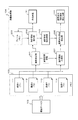
(2−2)実施例2
図8は、第2の実施例による画像処理の概念図である。時間経過に伴い、露光時間(T1)の画像1、露光時間(T2)の画像2、露光時間(T3)の画像3、露光時間(T4)の画像4・・・これらの画像が順次入力されて処理が行われる。
実施例1との違いは、合成に使う画像の選択方法である。実施例1と異なり、1つの被合成画像(画像n)が出力される度に合成を行う。
(2-2) Example 2
FIG. 8 is a conceptual diagram of image processing according to the second embodiment. As time passes,
The difference from the first embodiment is the method of selecting an image used for composition. Unlike Example 1, the composition is performed every time one composite image (image n) is output.
画像合成部201は、以下のように画像合成処理を実行する。
複数の異なる露光時間T1〜T4(T1<T2<T3<T4)の画像1〜画像4を適用した画像合成処理により、合成画像a,141aを生成する。
次に、露光時間T1〜T4(T1<T2<T3<T4)の画像2〜画像5を適用した画像合成処理により、合成画像b,141bを生成する。
以下、同様の処理を繰り返し、画像n〜n+3の4画像の合成処理の後、画像n+1〜n+4の4画像の合成処理を実行し、1画像ずつずらした4画像の組み合わせで合成画像を順次生成する。
The
Composite images a and 141a are generated by image composition
Next, composite images b and 141b are generated by image composition processing using images 2 to 5 with exposure times T1 to T4 (T1 <T2 <T3 <T4).
Thereafter, the same processing is repeated, and after the synthesis process of the four images n to n + 3, the synthesis process of the four images n + 1 to n + 4 is executed, and a synthesized image is sequentially generated by combining the four images shifted by one image. To do.
動き領域検出部202は、画像合成部201の生成した2つの合成画像を比較して動き領域を判別する。すなわち、
画像1〜4の合成処理により生成した合成画像a,141a、
画像2〜5の合成処理により生成した合成画像b,141b、
このように連続して生成した2つの合成画像を比較して画像に含まれる動き領域を検出する。
このように連続して生成した2つの合成画像を比較して画像に含まれる動き領域を検出する。この検出結果を動き領域検出情報143として出力する。
The motion
Composite images a and 141a generated by the composite processing of the
Combined images b and 141b generated by combining the images 2 to 5,
Two synthesized images generated in this way are compared to detect a motion region included in the image.
Two synthesized images generated in this way are compared to detect a motion region included in the image. This detection result is output as motion
動き領域検出部202の処理は、実施例1と同様である。すなわち、現在の合成画像(合成画像b,141b)と、過去の合成画像(合成画像a,141a)において、被写体が動かない場合、同一座標の画素値は一致し、図6に示す傾きが1の直線上にのるはずである。
The processing of the motion
合成画像aと合成画像bの対応座標位置の画素値が図6に示す傾き1のライン上にのれば、被写体は静止していると判断する。図6に示す傾き1のライン上からずれていれば動き領域であると判断する。ただし、前述した式(式1)を参照して説明したように、利用する固体撮像素子の性能等に応じて決定した差分許容値[Th1]を利用し、差分許容値[Th1]以上の画素値差分が検出された画素領域は動き領域であると判定するという処理を行うのが好ましい。
If the pixel value of the corresponding coordinate position of the composite image a and the composite image b is on the line with the
動き領域検出部202は、動き領域画素と動き領域でない画素を判別する情報を動き領域検出情報143として出力する。動き領域検出情報143は、例えば、画像の画素単位で動き領域画素=1、動き領域でない画素=0とした画素対応の動き領域検出情報等によって構成される。
The motion
この図8に示す実施例2の処理は、図4を参照して説明した実施例1と比べて、各合成画像間の時間的な間隔が近くなるため動被写体の移動距離を短くすることができる。ただしは画像処理装置内で実行する画像処理は高速に行うことが必要となる。例えば画像の入力レートと同様の出力レートの画像を合成して出力する処理が必要となる。 The processing of the second embodiment shown in FIG. 8 can shorten the moving distance of the moving subject because the time interval between the synthesized images is closer than that of the first embodiment described with reference to FIG. it can. However, image processing executed in the image processing apparatus needs to be performed at high speed. For example, it is necessary to synthesize and output an image having an output rate similar to the image input rate.
図9、図10は本実施例の画像処理部104の処理を説明するブロック図である。まず、図9、図10を参照して、本実施例の処理について説明する。撮像デバイス102は、まず、図9に示すように、画像111〜114(露光時間=T1〜T4)を出力し、これをメモリ103に保存する。
9 and 10 are block diagrams for explaining the processing of the
画像処理部104は、これらの画像111〜114(露光時間=T1〜T4)を入力し、画像合成部201において画像合成処理を実行し、合成画像を生成する。画像合成部201は、先に図6を参照して説明したように、輝度に応じて異なる露光時間の画像を組み合わせて、飽和画素値となる白とび画素を排除した合成画像を生成する。また、画像合成部201は、先に図8を参照して説明したように、4種類の異なる露光時間の画像4枚を1セットとして、順次、1画像ずつずらせた4枚セット単位で合成画像を生成する。
The
図9は、メモリ103に、画像1,111〜画像4,114が格納され、これらの画像1〜4の合成処理により合成画像a,141a(図8参照)を生成するタイミングの例を示す図である。
図10は、メモリ103に、その次の画像5,115が入力され、これらメモリ103に格納された画像2,112〜画像5,115の合成処理により合成画像b,141b(図8参照)を生成するタイミングの例を示す図である。
FIG. 9 is a diagram illustrating an example of timing at which the
In FIG. 10, the
画像合成部201の生成した合成画像は、動き領域検出部202に入力する。動き領域検出部202は、例えば4枚の画像(画像1〜画像4)による合成画像aと、その次の4枚の画像(画像2〜画像5)による合成画像bを続けて入力する場合、先行して入力した合成画像aを通過させて出力(合成画像141)するとともに、フレームメモリ203に保存する。
The composite image generated by the
動き領域検出部202は、後続する4枚の画像による合成画像bを画像合成部201から入力すると、先行合成画像aをフレームメモリ203から読み出し、先行合成画像aと、画像合成部201から入力する後続合成画像bと比較する。
When the synthesized image b composed of the subsequent four images is input from the
動き領域検出部202は、合成画像aと合成画像bの画素値の比較を実行する。すなわち、対応する同一画素位置毎に画素値比較を実行する。被写体の動きがない場合、理想的には、図6を参照して説明したように、合成画像aと合成画像bの対応する座標の画素値は、図6に示す傾き1のライン上にのる。
The motion
合成画像aと合成画像bの対応座標位置の画素値が図6に示す傾き1のライン上にのれば、被写体は静止していると判断する。図6に示す傾き1のライン上からずれていれば動き領域であると判断する。ただし、前述した式(式1)を参照して説明したように、利用する固体撮像素子の性能等に応じて決定した差分許容値[Th1]を利用し、差分許容値[Th1]以上の画素値差分が検出された画素領域は動き領域であると判定するという処理を行うのが好ましい。
If the pixel value of the corresponding coordinate position of the composite image a and the composite image b is on the line with the
動き領域検出部202は、例えば、上記式(式1)を満足する画素は動き領域であると判定し、上記式を満足しない画素は、動き領域でないと判定する。
動き領域検出部202は、動き領域画素と動き領域でない画素を判別する情報を動き領域検出情報143として出力する。動き領域検出情報143は、例えば、画像の画素単位で動き領域画素=1、動き領域でない画素=0とした画素対応の動き領域検出情報等によって構成される。
For example, the motion
The motion
本実施例は、前述の特許文献1(特開2008−99158号公報)に記載された構成を持つ撮像素子の他、一般的な通常の固体撮像素子、具体的には、一般的なCCDイメージセンサやCMOS(Complementary Metal Oxide Semiconductor)イメージセンサのような固体撮像素子が適用可能である。 In this embodiment, in addition to the image sensor having the configuration described in Patent Document 1 (Japanese Patent Laid-Open No. 2008-99158), a general normal solid-state image sensor, specifically, a general CCD image is used. A solid-state imaging device such as a sensor or a CMOS (Complementary Metal Oxide Semiconductor) image sensor is applicable.
(2−3)実施例3
先に説明した実施例1の処理は、図4等を参照して説明したように露光時間T1〜T4の4枚の画像を1セットとして、重なりのない4枚画像セット単位で合成画像を生成し、その合成画像同士を比較して動き領域の検出を実行する処理である。
(2-3) Example 3
In the processing of the first embodiment described above, as described with reference to FIG. 4 and the like, four images having exposure times T1 to T4 are set as one set, and a composite image is generated in units of four image sets that do not overlap. In this process, the synthesized images are compared with each other to detect a motion region.
この実施例1の処理は非常に単純であるが、画素値の比較対象となる2つの合成画像の撮影時間の間隔が離れている。このように比較対象となる合成画像の時間間隔が離れると、例えば動きの遅い動被写体であっても動き領域と判定される可能性が高くなる。 The processing of the first embodiment is very simple, but the interval between the shooting times of two composite images to be compared with pixel values is separated. In this way, when the time interval of the composite images to be compared is separated, there is a high possibility that even a moving subject that moves slowly, for example, is determined as a moving region.
このように比較対象の2つの合成画像の時間的間隔が離れると、合成画像間の画素値比較処理で画素値差分が検出され動き領域と判定された画素領域であっても、1つの合成画像の合成元の複数の異なる露光画像間の対応画素の画素値の差分は小さく動き領域と判断するほどの差分でない場合がある。これは、合成画像の構成対象となる異なる露光画像間の撮影時間間隔は、合成画像相互の撮影時間の間隔に比較して短いためである。 When the time interval between the two composite images to be compared is separated as described above, even if the pixel value difference is detected by the pixel value comparison process between the composite images and the pixel region is determined as the motion region, one composite image The difference between the pixel values of the corresponding pixels between a plurality of different exposure images of the composition source may be small and not so large as to be determined as a motion region. This is because the shooting time interval between different exposure images to be composed images is shorter than the shooting time interval between the combined images.
このように実施例1では画素値比較を行う合成画像の撮影時間間隔が長いため、動き領域の検出が過剰になる傾向がある。実施例3は、このような過剰検出を除外する手法を含めた構成例である。 As described above, in the first embodiment, since the shooting time interval of the composite image for comparing the pixel values is long, detection of the motion region tends to be excessive. Example 3 is a configuration example including a method for excluding such excessive detection.
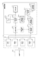
図11は第3の実施例による画像処理の概念図である。時間経過に伴い、露光時間(T1)の画像1、露光時間(T2)の画像2、露光時間(T3)の画像3、露光時間(T4)の画像4・・・これらの画像が順次入力されて処理が行われる。
FIG. 11 is a conceptual diagram of image processing according to the third embodiment. As time passes,
合成画像を生成する画像の組み合わせは図4を参照して説明した実施例1と同様である。すなわち、
複数の異なる露光時間T1〜T4(T1<T2<T3<T4)の画像1〜画像4を適用した画像合成処理により、合成画像a,141aを生成する。
次に、露光時間T1〜T4(T1<T2<T3<T4)の画像2〜画像5を適用した画像合成処理により、合成画像b,141bを生成する。
The combination of images for generating a composite image is the same as that in the first embodiment described with reference to FIG. That is,
Composite images a and 141a are generated by image composition
Next, composite images b and 141b are generated by image composition processing using images 2 to 5 with exposure times T1 to T4 (T1 <T2 <T3 <T4).
図4を参照して説明した実施例1との違いは、合成前画像比較部205を有する点である。合成前画像比較部205は、合成前の被合成画像(画像n)の画素同士で出力値の比較をし、比較結果を動き領域検出部202に出力する。
The difference from the first embodiment described with reference to FIG. 4 is that a pre-combine
動き領域検出部202は、合成前画像比較部205から入力する合成前の被合成画像(画像n)の画素同士の画素値比較結果情報を用いて、合成画像相互の画素値比較において動き領域として判定された領域の再検証を行う。合成画像相互の画素値比較において動き領域として判定された領域であっても、合成前の被合成画像(画像n)の画素同士の画素値比較結果が予め規定した画素値差分以下である場合は、動き領域でないと判定する。すなわち合成画像相互の画素値比較において動き領域として過剰に判定された部分を除外する処理を行う。
The motion
合成前画像比較部205は、合成前の被合成画像、すなわち、異なる露光時間T1〜T4(T1<T2<T3<T4)の各画像の対応画素の画素値比較を実行する。この場合、各露光時間に基づいて算出される出力画素値同士を比較することが必要となる。
The pre-combine
この処理は、先に従来技術の欄で説明した特許文献2(特開2000−50151号公報)の処理、すなわち、先に図2を参照して説明した長時間露光画像(LE)の出力値(輝度)と、短時間露光画像(SE)の出力値(輝度)との対応関係の比較処理に相当する。すなわち、長時間露光画像(LE)の出力値(輝度)と、短時間露光画像(SE)の出力値(輝度)が図2に示す傾きA(=露光比)のライン上に設定されれば、長時間露光画像(LE)と短時間露光画像(SE)の対応画素はまったく同じ輝度の被写体を撮影していると判定できる。 This process is the process of Patent Document 2 (Japanese Patent Laid-Open No. 2000-50151) described in the section of the prior art, that is, the output value of the long exposure image (LE) described above with reference to FIG. This corresponds to the comparison process of the correspondence between (luminance) and the output value (luminance) of the short-time exposure image (SE). That is, if the output value (luminance) of the long exposure image (LE) and the output value (luminance) of the short exposure image (SE) are set on the line of slope A (= exposure ratio) shown in FIG. It can be determined that the corresponding pixels of the long-exposure image (LE) and the short-exposure image (SE) are photographing a subject with exactly the same brightness.
すなわち、同一の被写体が撮影されている場合、長時間露光画像(LE)の出力値(輝度)と、短時間露光画像(SE)の出力値(輝度)との対応関係は、図2に示すような傾きA(=露光比)のライン上に設定されることになり、このラインからずれている場合は、動きの発生した領域であると判断するものである。 That is, when the same subject is photographed, the correspondence between the output value (luminance) of the long exposure image (LE) and the output value (luminance) of the short exposure image (SE) is shown in FIG. It is set on a line having such an inclination A (= exposure ratio), and if it is deviated from this line, it is determined that the region has moved.
しかしながら、前述したように、現実的には撮像素子を構成するPDやトランジスタの特製にはばらつきがあり、(LE−SE×A)=0を満足するか否かによって被写体の動きの有無を正確に判別することは困難である。例えば、閾値(Th)を設定して、|LE−SE×A|<Thを満足するか否かによって判別すれば、多少の素子のばらつきを吸収できるが、素子のばらつきは各装置によっても異なり、最適な閾値を設定することが難しいという問題がある。 However, as described above, in reality, there are variations in the special characteristics of PDs and transistors constituting the image sensor, and the presence or absence of movement of the subject is accurately determined depending on whether or not (LE-SE × A) = 0 is satisfied. It is difficult to discriminate them. For example, if a threshold value (Th) is set and it is determined whether or not | LE−SE × A | <Th is satisfied, some element variations can be absorbed, but the element variations vary depending on each device. There is a problem that it is difficult to set an optimum threshold value.
本実施例では、この異なる露光時間の画像の比較における問題点を解決する手法を用いる。長時間露光画像の出力値と、短時間露光画像の出力値は、撮像素子の特性によっては、例えば図12に示す特性となる。
図12は、先に説明した図2と同様、長時間露光画像(LE)の出力値(輝度)と、短時間露光画像(SE)の出力値(輝度)との対応関係をグラフとして示している。
In this embodiment, a technique for solving the problem in the comparison of images having different exposure times is used. The output value of the long exposure image and the output value of the short exposure image have the characteristics shown in FIG. 12, for example, depending on the characteristics of the image sensor.
FIG. 12 is a graph showing the correspondence between the output value (luminance) of the long exposure image (LE) and the output value (luminance) of the short exposure image (SE), as in FIG. Yes.
例えば、前述の特許文献1(特開2008−99158号公報)に開示された撮像素子の特性は図12に示す特性を持つ。すなわち、短時間露光の出力は、長時間露光の出力がある一定のレベル以上になるまで現れない(図12の領域1)。これは、先に説明した図1において、被写体の明るさが中間電圧の保持レベルを超えないと、短時間露光の出力が現れないことを意味している。
For example, the characteristics of the image sensor disclosed in Patent Document 1 (Japanese Patent Laid-Open No. 2008-99158) described above have the characteristics shown in FIG. That is, the short-time exposure output does not appear until the long-time exposure output exceeds a certain level (
中間電圧の保持レベルを超えると短時間露光側に出力が発生する。ただし、この出力発生時点の短時間露光側の出力値は極めて不安定となる。短時間露光の露光期間中を通して中間電圧の保持レベルを超えていないと正しい出力が出ないため、この間は露光比で決定される傾きとは異なる(図12の領域2)。なお、露光比は、長時間露光画像(LE)と短時間露光画像(SE)との露光量の比である露光比A(=LE/SE)である。 When the holding level of the intermediate voltage is exceeded, an output is generated on the short exposure side. However, the output value on the short-time exposure side when this output is generated becomes extremely unstable. Since the correct output cannot be obtained unless the holding level of the intermediate voltage is exceeded during the exposure period of the short exposure, the slope determined by the exposure ratio is different during this period (region 2 in FIG. 12). The exposure ratio is an exposure ratio A (= LE / SE), which is a ratio of the exposure amount between the long exposure image (LE) and the short exposure image (SE).
これは、短時間露光処理がフォトダイオード(PD)の蓄積電荷の掃き出しと、その後の短時間露光の実行という複雑な処理によって行われること等に起因する。すなわち、先に図1を参照して説明したように、短時間露光処理は、図1に示す時間t1(電荷掃き出し開始点P1)において、一旦、フォトダイオード(PD)において制御される中間電圧保持レベルまで受光フォトダイオード(PD)の蓄積電荷を掃き出し、この電荷掃き出し処理の後、再度、露光時間TS(t2〜t3)とした露光処理によって行われる。 This is due to the fact that the short-time exposure process is performed by a complicated process of sweeping out the accumulated charge of the photodiode (PD) and then executing the short-time exposure. That is, as described above with reference to FIG. 1, the short-time exposure process is performed by holding the intermediate voltage once controlled in the photodiode (PD) at time t1 (charge sweep start point P1) shown in FIG. The charge accumulated in the light receiving photodiode (PD) is swept out to the level, and after the charge sweeping process, the exposure process is performed again with the exposure time TS (t2 to t3).
図12の領域2は、短時間露光処理の開始直後のフォトダイオード(PD)の蓄積電荷量に基づいて算出される出力値であり、この部分は、極めて不安定な出力となり、長時間露光画像(LE)と短時間露光画像(SE)の出力値の対応(傾きB)は、露光量の比である露光比A(=LE/SE)で決定される傾きとは異なる傾きB(≠傾きA(露光比))に設定される。 Region 2 in FIG. 12 is an output value calculated based on the accumulated charge amount of the photodiode (PD) immediately after the start of the short-time exposure processing, and this portion is an extremely unstable output, and the long-exposure image (LE) and the correspondence between the output values of the short-exposure image (SE) (slope B) are different from the slope determined by the exposure ratio A (= LE / SE), which is the ratio of the exposure amounts, (not slope) A (exposure ratio)).
その後の領域3は、短時間露光処理の行われるフォトダイオード(PD)の電化蓄積が安定した状態における出力値となるため、露光比から算出できる一定の傾きA(露光比)となる。以上の関係は、3枚以上の画像を合成する場合でも同様である。 The subsequent region 3 has an output value in a state in which the charge and accumulation of the photodiode (PD) subjected to the short-time exposure process is stable, and thus has a constant slope A (exposure ratio) that can be calculated from the exposure ratio. The above relationship is the same even when three or more images are combined.
このように、先に説明した図2の長時間露光画像の出力値と、短時間露光画像の出力値の対応関係は、あくまでも理論的な関係であり、現実の撮像素子の出力値には対応しない。対応関係は、撮像素子の特性に依存することになり、長時間露光画像の出力値と、短時間露光画像の出力値の関係は、例えば図12に示す関係となる場合が多い。 As described above, the correspondence relationship between the output value of the long-time exposure image and the output value of the short-time exposure image in FIG. 2 described above is a theoretical relationship to the last, and corresponds to the actual output value of the image sensor. do not do. The correspondence relationship depends on the characteristics of the image sensor, and the relationship between the output value of the long exposure image and the output value of the short exposure image is often the relationship shown in FIG. 12, for example.
これらの事情を考慮し、図11に示す合成前画像比較部205では、合成前の異なる露光時間の被合成画像(画像n)の画素同士の出力値の比較を行う場合、図12に示す領域3、すなわち、予め設定した閾値輝度レベル(図12のTh2)以上の輝度を持つ画素についてのみ比較対象画素として選択し、選択した画素についてのみの画素値比較処理を行う。
なお、閾値輝度レベル(図12のTh2)は、撮像素子の特性に応じて決定され、短時間露光において出力が安定する輝度レベルに応じて予め規定する。
In consideration of these circumstances, in the pre-combine
Note that the threshold luminance level (Th2 in FIG. 12) is determined according to the characteristics of the image sensor, and is defined in advance according to the luminance level at which the output is stable in short-time exposure.
合成前画像比較部205は、予め設定した閾値輝度レベル(図12のTh2)以上の輝度を持つ画素について、被合成画像となる長時間露光画像の出力値と、短時間露光画像の出力値とを比較し、比較結果を過検出除去部203(図13参照)に出力する。過検出除去部203は、動き領域検出部202が合成画像同士の画素値比較結果において動き領域と判定した画素領域について、合成前画像比較部205からの受領情報に基づいて再検証を行う。
The pre-combine
すなわち、合成画像同士の画素値比較結果において動き領域と判定した画素領域であっても、被合成画像となる長時間露光画像の出力値と、短時間露光画像の出力値の差分が予め設定した閾値未満である場合は、動き領域でないと判断し、動き領域の判定を取り消す。 That is, the difference between the output value of the long-time exposure image and the output value of the short-time exposure image, which is the composite image, is set in advance even in the pixel region determined as the motion region in the pixel value comparison result between the composite images. If it is less than the threshold, it is determined that the region is not a motion region, and the motion region determination is cancelled.
図13は本実施例の画像処理装置のブロック図を示す図である。図7との差異は、合成前比較部205と過検出除去部206を有する点である。
FIG. 13 is a block diagram of the image processing apparatus according to the present embodiment. The difference from FIG. 7 is that a
撮像デバイス102は画像115〜118(露光時間=T1〜T4)を出力し、これをメモリ103に保存する。画像処理部104は、これらの画像115〜118(露光時間=T1〜T4)を入力し、画像合成部201において画像合成処理を実行し、合成画像を生成する。なお、図13では、先行する画像111〜114(露光時間=T1〜T4)による合成画像が既にフレームメモリ203に格納されているものとして説明する。
The
画像合成部201は、先に図6を参照して説明したように、輝度に応じて異なる露光時間の画像を組み合わせて、飽和画素値となる白とび画素を排除した合成画像を生成する。画像合成部201の生成した合成画像は、動き領域検出部202に入力する。動き領域検出部202は、例えば4枚の画像による合成画像aと、その次の4枚の画像による合成画像bを続けて入力する場合、先行して入力した合成画像aを通過させて出力(合成画像141)するとともに、フレームメモリ203に保存する。
As described above with reference to FIG. 6, the
動き領域検出部202は、後続する4枚の画像による合成画像bを画像合成部201から入力すると、先行合成画像aをフレームメモリ203から読み出し、先行合成画像aと、画像合成部201から入力する後続合成画像bと比較する。
When the synthesized image b composed of the subsequent four images is input from the
合成画像aと合成画像bの対応座標位置の画素値が図6に示す傾き1のライン上にのれば、被写体は静止していると判断する。図6に示す傾き1のライン上からずれていれば動き領域であると判断する。ただし、前述した式(式1)を参照して説明したように、利用する固体撮像素子の性能等に応じて決定した差分許容値[Th1]を利用し、差分許容値[Th1]以上の画素値差分が検出された画素領域は動き領域であると判定するという処理を行うのが好ましい。
If the pixel value of the corresponding coordinate position of the composite image a and the composite image b is on the line with the
本実施例では、動き領域検出部202の検出結果は、過検出除去部206に入力される。過検出除去部206は、合成画像aと合成画像bの対応座標位置の画素値比較に基づいて動き領域とし判定した画素領域の再検証を行い、過検出であると判断された動き領域画素を動き領域でないとする過検出除去処理を行う。
In the present embodiment, the detection result of the motion
すなわち、過検出除去部206は、合成前画像比較部205から被合成画像となる長時間露光画像の出力値と、短時間露光画像の出力値とを比較結果を入力して、合成画像同士の画素値比較結果において動き領域と判定した画素領域について、被合成画像となる長時間露光画像の出力値と、短時間露光画像の出力値の差分が予め設定した閾値未満である場合は、動き領域でないと判断し、動き領域の判定を取り消す過検出除去処理を行う。
That is, the
なお、合成前画像比較部205は、前述したように予め設定した閾値輝度レベル(図12のTh2)以上の輝度を持つ画素について、被合成画像となる長時間露光画像の出力値と、短時間露光画像の出力値とを比較し、比較結果を動き領域検出部202の過検出除去部206に出力する。
Note that the pre-combine
合成前比較部205は、前述の式(式1)同様、ある程度の許容量を設定し、以下の式(式2)を適用して動き領域の判定を行う。図12に示す領域3にあって、以下の式2を満たす場合、動き領域ではないと判定して動き領域の除去対象とする。
短時間露光画像(例えば画像5(T1)115)
長時間露光画像(例えば画像6(T2)116)
を比較対象とした場合、
短時間露光画像の出力×0.1>|長時間露光画像の出力−短時間露光画像の出力×A)|
・・・(式2)
なお、Aは長時間露光画像(LE)と短時間露光画像(SE)の露光量の比である露光比A(=LE/SE)である。
The
Short exposure image (for example, image 5 (T1) 115)
Long exposure image (for example, image 6 (T2) 116)
Is the comparison target,
Output of short exposure image × 0.1> | Output of long exposure image−Output of short exposure image × A) |
... (Formula 2)
A is an exposure ratio A (= LE / SE) which is a ratio of the exposure amount of the long exposure image (LE) and the short exposure image (SE).
上記式(式2)は、例えば露光比A=10であれば、長時間露光画像:画像6(T2)116の出力値から、短時間露光画像:画像5(T1)115の出力値を10倍した値を差し引いた絶対値をみる、という意味である。 For example, if the exposure ratio A = 10, the above expression (Expression 2) is obtained by changing the output value of the short exposure image: image 5 (T1) 115 from the output value of the long exposure image: image 6 (T2) 116 to 10. It means to look at the absolute value minus the doubled value.
このように、過検出除去部206は、動き領域検出部202が合成画像間の画素値比較に基づいて動き領域と判定した画素領域であっても、図12に示す領域3にあって、以下の式2を満たす場合、その領域は動き領域ではないとして動き領域から除去する処理を行う。
As described above, the
なお、比較処理は、全ての合成前画像の組み合わせで行うのではなく、合成画像の生成時に合成画像の構成画素として選択された画像(選択情報は画像合成部102より入手)の前後で行う。つまり、例えば合成画像の特定画素の有効画素値として、画像6(T2)116の画素が選択された場合、画像6(T2)116と画像5(T1)115、および、画像6(T2)116と画像7(T3)117を比較する。 Note that the comparison process is not performed for all the pre-combination image combinations, but before and after the image selected as the constituent pixel of the composite image when the composite image is generated (selection information is obtained from the image composition unit 102). That is, for example, when the pixel of the image 6 (T2) 116 is selected as the effective pixel value of the specific pixel of the composite image, the image 6 (T2) 116, the image 5 (T1) 115, and the image 6 (T2) 116 are selected. And image 7 (T3) 117 are compared.
このように、動き領域検出部202は、
(1)合成画像相互の画素値比較による動き領域の検出、
この検出処理を実行し、
過検出除去部206は、
(2)合成画像の生成元画像である被合成画像間の画素値比較による動き領域の再検出、
この処理を実行し、過検出除去部206は、これらの2段階の処理において、双方で動き領域であると判定された画素領域のみを最終的な動き領域であると判断して動き領域検出情報143を出力する。
動き領域検出情報143は、例えば、画像の画素単位で動き領域画素=1、動き領域でない画素=0とした画素対応の動き領域検出情報等によって構成される。
Thus, the motion
(1) Detection of a motion region by comparing pixel values of synthesized images
Run this detection process,
The over
(2) Re-detection of a motion region by comparing pixel values between composite images that are generation images of composite images;
By executing this processing, the
The motion
本実施例は、前述の特許文献1(特開2008−99158号公報)に記載された構成を持つ撮像素子の他、一般的な通常の固体撮像素子、具体的には、一般的なCCDイメージセンサやCMOS(Complementary Metal Oxide Semiconductor)イメージセンサのような固体撮像素子が適用可能である。なお、撮像素子の特性により、長時間露光画像の出力値と、短時間露光画像の出力値の関係が、図12のような関係となる場合、図2のような関係となる場合、あるいはその他の関係となる場合がある。合成前画像比較部205は、利用する撮像素子の特性に応じて判定領域を絞り込んで判定を行う構成とするのが好ましい。
In this embodiment, in addition to the image sensor having the configuration described in Patent Document 1 (Japanese Patent Laid-Open No. 2008-99158), a general normal solid-state image sensor, specifically, a general CCD image is used. A solid-state imaging device such as a sensor or a CMOS (Complementary Metal Oxide Semiconductor) image sensor is applicable. Depending on the characteristics of the image sensor, when the relationship between the output value of the long exposure image and the output value of the short exposure image is as shown in FIG. 12, as shown in FIG. 2, or otherwise. It may be a relationship. The pre-combination
(2−4)実施例4
次に、本発明の画像処理装置の実施例4として、動き領域からさらに画質劣化を引き起こす可能性の高い画質劣化領域を検出する構成例について説明する。
(2-4) Example 4
Next, as a fourth embodiment of the image processing apparatus according to the present invention, a configuration example for detecting an image quality degradation region that is more likely to cause image quality degradation from a motion region will be described.
例えば、R、G、Bのカラーフィルタを用いた単板型固体撮像素子を用いた場合(カラーフィルタの色は任意で良い)、動被写体を撮影した際に、画質的に劣化がひどくなるのは、生成した合成画像を構成する画素の隣接画素位置にあるR、G、B画素が、それぞれ違う被合成画像から選択されて合成された場合である。 For example, when a single-plate solid-state imaging device using R, G, and B color filters is used (the color of the color filter may be arbitrary), when moving subjects are photographed, the image quality deteriorates severely. Is a case where R, G, and B pixels at adjacent pixel positions of the pixels constituting the generated combined image are selected from different combined images and combined.
具体例としては、例えば合成画像を構成する画素において、
G画素が、露光時間T2の画像112(T2)から選択され、
G画素に隣接するR画素とB画素が露光時間T4の画像114(T4)から選択されたといった場合である。
このような合成処理を行った場合、静止画であれば問題は少ないが、動被写体を撮影している場合は、露光時間、露光期間が異なる画像を近接の画素で用いることになる。このため、その後、デモザイク(補間)処理を行いカラー画像として観察すると、画質劣化を引き起こし特に偽色などを発生することになる。
As a specific example, for example, in a pixel constituting a composite image,
G pixels are selected from the image 112 (T2) of exposure time T2,
This is a case where the R pixel and the B pixel adjacent to the G pixel are selected from the image 114 (T4) having the exposure time T4.
When such a composition process is performed, there is little problem with a still image, but when a moving subject is photographed, images having different exposure times and exposure periods are used in adjacent pixels. For this reason, when a demosaic (interpolation) process is subsequently performed and the image is observed as a color image, the image quality is deteriorated and a false color or the like is generated.
なお動被写体を撮影していても隣接する画素同士が同じ被合成画像を選択していれば、画質の劣化はそれほどでもない。これは、同じ露光時間、露光期間の画像を表現できているからである。少なくとも、偽色などを発生することはない。 Even if a moving subject is photographed, if adjacent pixels select the same composite image, the image quality is not degraded so much. This is because images having the same exposure time and exposure period can be expressed. At least, no false color is generated.
図14は、本実施例のコンセプトを説明する図である。
例えば上述した実施例1〜3のいずれかの手法で検出された動き領域は、図14に示す大きな領域である「動き領域」であり、その内部に、特に画質劣化(偽色など)を発生する「画質劣化領域」が包含される。
FIG. 14 is a diagram for explaining the concept of this embodiment.
For example, the motion region detected by any one of the methods of the first to third embodiments described above is a “motion region” that is a large region shown in FIG. “Image quality degradation region” is included.
本実施例4の画像処理装置は、動被写体が含まれると判断された「動き領域」の構成画素の中から、隣接画素間で採用されている被合成画像が異なる画素を抽出し、これらを「画質劣化領域」の構成画素として検出する。 The image processing apparatus according to the fourth embodiment extracts pixels having different synthesized images adopted between adjacent pixels from the constituent pixels of the “motion region” determined to include the moving subject, and extracts these. It is detected as a constituent pixel of the “image quality degradation region”.
図15は、本実施例の画像処理装置のブロック図を示す図である。図7との差異は、選択画像比較部207と画質劣化領域検出部208を有する点である。
その他の構成については図7と同様であるため説明を省略する。以下、図7の構成と異なる点について説明する。
FIG. 15 is a block diagram of the image processing apparatus according to the present embodiment. The difference from FIG. 7 is that a selected
Other configurations are the same as those in FIG. Hereinafter, differences from the configuration of FIG. 7 will be described.
選択画像比較部207は、画像合成部201における画像合成処理において生成した合成画像の各構成画素が、どの被合成画像(画像1〜画像4)の画素から選択されたかを示す選択画像情報を画像合成部201から入力して、異なる画像から選択された隣接画素について、画質劣化領域検出対象として設定する処理を行う。
The selected
図16を参照して、選択画像比較部207の実行する処理について説明する。図16には、
(a)画質劣化領域検出対象としない例
(b)画質劣化領域検出対象とする例
これらの2つの例を示している。いずれも判定対象は9画素中の中心画素である。
Processing executed by the selected
(A) Example not to be an image quality degradation area detection target (b) Example to be an image quality degradation area detection target These two examples are shown. In any case, the determination target is the central pixel of the nine pixels.
(a)画質劣化領域検出対象としない例
この例では、判定対象とする中心画素が画像1(T1)からの選択画素によって構成され、その周囲画素の8画素のすべてが、中心画素と同じ画像1(T1)からの選択画素によって構成されている。
このように中心画素である判定画素の周囲の全画素が中心画素と同一の画像から選択されている場合は、画質劣化の可能性がないと判定して、画質劣化領域検出対象としない。
(A) Example in which image quality degradation area detection target is not used In this example, the central pixel to be determined is composed of selected pixels from the image 1 (T1), and all of the 8 surrounding pixels are the same image as the central pixel. 1 (T1).
As described above, when all the pixels around the determination pixel as the center pixel are selected from the same image as the center pixel, it is determined that there is no possibility of image quality deterioration, and the image quality deterioration area is not detected.
(b)画質劣化領域検出対象とする例
一方、図16(b)に示す例では、判定対象とする中心画素が画像1(T1)からの選択画素によって構成され、その周囲画素の8画素中2画素が、中心画素と異なる画像2(T2)からの選択画素によって構成されている。
このように中心画素である判定画素の周囲に中心画素と異なる画像から選択されたが素が含まれる場合は、画質劣化の可能性があると判定して、画質劣化領域検出対象とする。
(B) Example of Image Quality Degraded Region Detection Target On the other hand, in the example shown in FIG. 16B, the central pixel to be determined is composed of selected pixels from the image 1 (T1), and among the eight surrounding pixels. Two pixels are constituted by selected pixels from the image 2 (T2) different from the central pixel.
As described above, when a pixel selected from an image different from the central pixel is included around the determination pixel that is the central pixel, it is determined that there is a possibility that the image quality is deteriorated, and the image quality deterioration area is detected.
選択画像比較部207は、このように、合成画像の構成画素について、画質劣化領域検出対象画素と、非検出対象画素とを区別した画素対応の判定情報を画質劣化領域検出部208に出力する。例えば、画質劣化領域検出対象画素=1、画質劣化領域非検出対象画素=0とした設定の合成画像の画素対応の画質劣化領域検出情報を画質劣化領域検出部208に出力する。
In this way, the selected
画質劣化領域検出部208は、選択画像比較部207から、この画質劣化領域検出情報を入力するとともに、動き領域検出部202から合成画像相互の画素値比較処理に基づいて生成された動き領域検出情報143を入力する。動き領域検出情報143は、例えば、合成画像の画素単位で動き領域画素=1、動き領域でない画素=0とした画素対応の動き領域検出情報等によって構成される。
The image quality degradation
画質劣化領域検出部208は、画質劣化領域検出情報と動き領域検出情報143から、最終的な画質劣化動き領域検出情報144を生成して出力する。
画質劣化領域検出部208は、各画素について、
動き領域画素=1であり、かつ画質劣化領域検出対象画素=1である画素のみを抽出して、この領域を画質劣化動き領域とする。
すなわち、画質劣化領域検出情報と動き領域検出情報143のアンド処理(ANDの論理演算)を行い、動き領域であり、かつ画質劣化領域検出対象でもある画素のみを抽出して画質劣化動き領域画素であると判定する。これら以外の画素は、画質劣化動き領域画素でないと判定し、これらの判定情報を画素単位で設定した画質劣化動き領域検出情報144を出力する。
The image quality degradation
For each pixel, the image quality degradation
Only the pixels where the motion area pixel = 1 and the image quality degradation area detection target pixel = 1 are extracted, and this area is set as the image quality degradation motion area.
That is, AND processing (AND logical operation) of the image quality degradation area detection information and the motion
画質劣化領域検出部208の出力する画質劣化動き領域検出情報144は、例えば、画質劣化動き領域画素=1、画質劣化動き領域でない画素=0とした画素対応の画質劣化動き領域検出情報等によって構成される。
The image quality degradation motion
本実施例は、前述の特許文献1(特開2008−99158号公報)に記載された構成を持つ撮像素子の他、一般的な通常の固体撮像素子、具体的には、一般的なCCDイメージセンサやCMOS(Complementary Metal Oxide Semiconductor)イメージセンサのような固体撮像素子が適用可能である。 In this embodiment, in addition to the image sensor having the configuration described in Patent Document 1 (Japanese Patent Laid-Open No. 2008-99158), a general normal solid-state image sensor, specifically, a general CCD image is used. A solid-state imaging device such as a sensor or a CMOS (Complementary Metal Oxide Semiconductor) image sensor is applicable.
(2−5)実施例5
次に、本発明の画像処理装置の実施例5として、画質劣化を引き起こしている可能性の高い領域の検出情報として画質劣化領域検出情報を出力する構成について図17を参照して説明する。
(2-5) Example 5
Next, as Embodiment 5 of the image processing apparatus of the present invention, a configuration for outputting image quality degradation area detection information as detection information of an area that is likely to cause image quality degradation will be described with reference to FIG.
図17は、本実施例の画像処理装置のブロック図を示す図である。撮像デバイス102、メモリ103の構成は図7を参照して説明した実施例1の構成と同様である。
画像処理部104の画像合成部201の処理も図7を参照して説明した実施例1の構成と同様であり、異なる露光時間の画像1〜4を適用して合成画像141を生成する。
FIG. 17 is a block diagram of the image processing apparatus according to the present embodiment. The configurations of the
The processing of the
出力値有効領域検出部209は、画像合成部201の生成した合成画像を構成する各画素が、どの被合成画像(画像1〜画像4)の画素から選択されたかを示す選択画像情報を画像合成部201から入力する。この選択情報は、図15を参照して説明した実施例4の選択情報と同様の情報である。
The output value effective
出力値有効領域検出部209は、この選択情報を入力し、合成画像を構成する全ての画素について、選択された画像、すなわちメモリ103に格納されている合成前の被合成画像(画像1〜4)の対応画素値を取得し、合成前画像の出力値の有効性を判定する。
The output value effective
例えば、画像の有効ビットが10bitデータによって構成され、ビット値の取り得る値、すなわちデジット値が(0〜1023digit)であった場合、その両端部のビット値は有効性が低いと判断する。具体的には、例えば、合成画像の構成画素のビット値(0〜1023digit)が、
ビット値>1000digit
または、
ビット値<5digit
・・・・(式3)
上記式(式3)を満足する場合は、この画素のビット値の有効性が低いと判断し、画質劣化領域であると判定する。
For example, when the effective bit of the image is composed of 10-bit data and the bit value can be taken, that is, the digit value is (0 to 1023 digit), it is determined that the bit values at both ends are low in effectiveness. Specifically, for example, the bit value (0 to 1023 digit) of the constituent pixels of the composite image is
Bit value> 1000 digits
Or
Bit value <5 digits
... (Formula 3)
When the above equation (Equation 3) is satisfied, it is determined that the validity of the bit value of this pixel is low, and it is determined that the region is an image quality degradation region.
ビット値>1000digit
この式を満足する画素は、画素値がほぼ飽和レベルに達している画素である。
また、
ビット値<5digit
この式を満足する画素は、画素値がほぼ零付近にある画素である。
このような画素は、正確な画素値が出力されている可能性が低いため、画素値の有効性の無い画素領域であると判定する。
Bit value> 1000 digits
A pixel that satisfies this equation is a pixel whose pixel value has almost reached the saturation level.
Also,
Bit value <5 digits
A pixel that satisfies this equation is a pixel having a pixel value near zero.
Since such a pixel is unlikely to output an accurate pixel value, it is determined that the pixel region has no pixel value validity.
出力値有効領域検出部209は、このように上記判定式(式3)に従って、合成画像の構成画素の画素値に基づいて、画素値が有効性の実も止められる画素値に設定されているか否かを判定し、判定結果を画素対応の有効性情報として設定した画質劣化領域検出情報145を生成して出力する。
Whether the output value effective
画質劣化領域検出情報145は、例えば、合成画像の画素単位で、上記式(式3)を満足する画素であることを示す画質劣化領域画素=1、上記式(式3)を満足する画素でないことを示す画質劣化領域でない画素=0とした画素対応の画質劣化領域情報等によって構成される。
The image quality degradation
(2−6)実施例6
次に、図18を参照して本発明の画像処理装置の実施例6の構成について説明する。
図18に示す画像処理装置は、図17に示す実施例5の変形例である。
図18に示す画像処理装置は、
図7を参照して説明した実施例1の構成と、
図17を参照して説明した実施例5の構成と、
を併せ持つ構成である。
(2-6) Example 6
Next, the configuration of the image processing apparatus according to the sixth embodiment of the present invention will be described with reference to FIG.
The image processing apparatus shown in FIG. 18 is a modification of the fifth embodiment shown in FIG.
The image processing apparatus shown in FIG.
The configuration of the first embodiment described with reference to FIG.
The configuration of the fifth embodiment described with reference to FIG.
It is the structure which has both.
画像合成部201における画像合成処理は、実施例1の処理と同様の処理である。
撮像デバイス102は画像111〜114(露光時間=T1〜T4)を出力し、これをメモリ103に保存する。画像処理部104は、これらの画像111〜114(露光時間=T1〜T4)を入力し、画像合成部201において画像合成処理を実行し、合成画像を生成する。
The image composition processing in the
The
図18に示す動き領域検出部202は、図7を参照して説明したと同様の処理を実行する。すなわち、合成画像間の画素値比較を実行して、合成画像の動き領域検出情報143を生成して画質劣化領域検出部208に出力する。
動き領域検出部202の生成する動き領域検出情報143は、例えば、合成画像の構成画素単位で動き領域画素=1、動き領域でない画素=0とした画素対応の動き領域検出情報等によって構成される。
The motion
The motion
一方、出力値有効領域検出部209は、画像合成部201の生成した合成画像を構成する各画素が、どの被合成画像(画像1〜画像4)の画素から選択されたかを示す選択画像情報を画像合成部201から入力して、合成画像を構成する全ての画素についての選択画像、すなわちメモリ103に格納されている合成前の被合成画像(画像1〜4)の対応画素値を取得し、合成前画像の出力値の有効性を判定する。
この処理は、図17を参照して説明した実施例5の出力値有効領域検出部209が実行する処理と同様の処理である。
On the other hand, the output value effective
This process is the same as the process executed by the output value valid
具体的には、出力値有効領域検出部209は、例えば、合成画像の構成画素の有効ビットが10bitデータによって構成され、ビット値の取り得る値、すなわちデジット値が(0〜1023digit)であった場合、その両端部のビット値は有効性が低いと判断する。具体的には、例えば、合成画像の構成画素のビット値(0〜1023digit)が、
ビット値>1000digit
または、
ビット値<5digit
・・・・(式3)
上記式(式3)を満足する場合は、この画素のビット値の有効性が低いと判断し、画質劣化領域であると判定する。判定結果を画素対応の有効性情報として設定した画質劣化領域検出情報145を生成して出力する。
Specifically, the output value effective
Bit value> 1000 digits
Or
Bit value <5 digits
... (Formula 3)
When the above equation (Equation 3) is satisfied, it is determined that the validity of the bit value of this pixel is low, and it is determined that the region is an image quality degradation region. Image quality degradation
画質劣化領域検出情報145は、例えば、合成画像の画素単位で上記式(式3)を満足する画素であることを示す画質劣化領域画素=1、上記式(式3)を満足する画素でないことを示す画質劣化領域でない画素=0とした画素対応の画質劣化領域情報等によって構成される。
The image quality deterioration
画質劣化領域検出部208は、画質劣化領域検出情報と動き領域検出情報143から、最終的な画質劣化動き領域検出情報144を生成して出力する。
画質劣化領域検出部208は、各画素について、
動き領域画素=1であり、かつ画質劣化領域画素=1である画素のみを抽出して、この領域を画質劣化動き領域とする。
すなわち、画質劣化領域検出情報145と動き領域検出情報143のアンド処理(ANDの論理演算)を行い、動き領域であり、かつ画質劣化領域でもある画素のみを抽出して、これらを画質劣化動き領域画素であると判定する。これら以外の画素は、画質劣化動き領域画素でないと判定し、これらの判定情報を画素単位で設定した画質劣化動き領域検出情報144を出力する。
The image quality degradation
For each pixel, the image quality degradation
Only the pixels where the motion region pixel = 1 and the image quality degradation region pixel = 1 are extracted, and this region is set as the image quality degradation motion region.
That is, AND processing (AND logical operation) of the image quality degradation
画質劣化領域検出部208の出力する画質劣化動き領域検出情報144は、例えば、画質劣化動き領域画素=1、画質劣化動き領域でない画素=0とした画素対応の画質劣化動き領域検出情報等によって構成される。
The image quality degradation motion
このように図18に示す実施例6の構成では、前述の実施例5と実施例1のそれぞれの結果をandした構成を有する。
本実施例6においても、実施例5と同様の画素値が飽和画素値に近い画素や0に近い画素を画質劣化領域として判定する処理を行うが、本実施例では、合成画像後のデータを利用した動き検出処理において、動き領域として検出されない領域は、画質劣化動き領域として選択されないことになる。
As described above, the configuration of the sixth embodiment shown in FIG. 18 has a configuration obtained by ANDing the results of the fifth embodiment and the first embodiment.
Even in the sixth embodiment, the same pixel value as in the fifth embodiment is determined as the image quality degradation region, but the pixel value close to the saturated pixel value is determined as the image quality degradation region. In the motion detection process used, a region that is not detected as a motion region is not selected as an image quality degradation motion region.
従って、合成画像の比較対象となる合成画像の対応画素値に、動き領域であると判定されるだけの画素値の差分がなければ、その領域は画質劣化動き領域から除外される、これにより、実施例5に比較して、過剰な画質劣化領域の検出を避けることができる。 Therefore, if the corresponding pixel value of the composite image to be compared with the composite image does not have a pixel value difference that is determined to be a motion region, the region is excluded from the image quality degradation motion region. Compared to the fifth embodiment, it is possible to avoid detection of an excessive image quality degradation region.
本実施例は、前述の特許文献1(特開2008−99158号公報)に記載された構成を持つ撮像素子の他、一般的な通常の固体撮像素子、具体的には、一般的なCCDイメージセンサやCMOS(Complementary Metal Oxide Semiconductor)イメージセンサのような固体撮像素子が適用可能である。 In this embodiment, in addition to the image sensor having the configuration described in Patent Document 1 (Japanese Patent Laid-Open No. 2008-99158), a general normal solid-state image sensor, specifically, a general CCD image is used. A solid-state imaging device such as a sensor or a CMOS (Complementary Metal Oxide Semiconductor) image sensor is applicable.
(2−7)実施例7
次に、図19、図20を参照して本発明の画像処理装置の実施例7の構成について説明する。
(2-7) Example 7
Next, the configuration of the image processing apparatus according to the seventh embodiment of the present invention will be described with reference to FIGS.
図19は、図5と同様の特性図である。長時間露光画像〜短時間露光画像の複数の画像の取得処理について説明する図である。図19において、横軸は時間(t)であり、縦軸は固体撮像素子の1つの画素に対応する光電変換素子を構成する受光フォトダイオード(PD)における蓄積電荷量(e)である。例えば、受光フォトダイオード(PD)の受光量が多い、すなわち明るい被写体に対応する場合、時間経過に伴う電荷蓄積量は急激に上昇する。一方、受光フォトダイオード(PD)の受光量が少ない、すなわち暗い被写体に対応する場合、時間経過に伴う電荷蓄積量は緩やかに上昇する。 FIG. 19 is a characteristic diagram similar to FIG. It is a figure explaining the acquisition process of the several image of a long exposure image-a short exposure image. In FIG. 19, the horizontal axis represents time (t), and the vertical axis represents the accumulated charge amount (e) in the light-receiving photodiode (PD) constituting the photoelectric conversion element corresponding to one pixel of the solid-state imaging element. For example, when the amount of light received by the light-receiving photodiode (PD) is large, that is, when the subject corresponds to a bright subject, the amount of accumulated charge increases with time. On the other hand, when the amount of light received by the light receiving photodiode (PD) is small, that is, when dealing with a dark subject, the amount of accumulated charge gradually increases with time.
図19は、動く被写体を撮り込む画素の処理を想定した図である。撮影の初期が明るく、次いで暗くなるケースを表している。図19において、初期(時間=tx〜ty)の明るい状況で信号が中間電位の保存レベルを超えるため、短時間露光の領域に入る。しかし、途中(時間=ty)で、被写体が移動して画素値は暗くなる。 FIG. 19 is a diagram assuming a pixel process for capturing a moving subject. This represents a case where the initial stage of shooting is bright and then darkens. In FIG. 19, since the signal exceeds the storage level of the intermediate potential in the initial bright state (time = tx to ty), a short exposure period is entered. However, in the middle (time = ty), the subject moves and the pixel value becomes dark.
明るい被写体が移動してしまい画素値が暗くなった後に、短時間露光が実行される。図19に示す短時間露光時間(T1〜T3)である。この期間は、すでに明るい被写体が移動してしまった後であるため、暗い被写体を撮り込んでいる状況であり、受光PD(フォトダイオード)の電荷蓄積スピードは低下し、図に示すラインの傾きが小さくなり寝ている。その後、長時間露光時間(T4)の経過後に長時間露光出力を得る。この場合、暗い被写体を撮りこんでいるため、時間t2以降の期間を傾きが小さくなり、画素の飽和レベルに至らない長時間露光出力が得られる。 Short exposure is performed after the bright subject moves and the pixel value becomes dark. This is the short exposure time (T1 to T3) shown in FIG. Since this period is after the bright subject has already moved, the dark subject is being photographed. The charge accumulation speed of the light-receiving PD (photodiode) decreases, and the slope of the line shown in FIG. I'm getting smaller and sleeping. Thereafter, a long exposure output is obtained after the long exposure time (T4) has elapsed. In this case, since a dark subject is captured, the slope of the period after time t2 becomes small, and a long-time exposure output that does not reach the pixel saturation level is obtained.
画像合成処理に際しては、短時間露光の出力値と長時間露光の出力値とを比較するが、この例では、短時間露光の出力は小さいため、長時間露光の出力が選択されることがある。ここで問題となるのは、この長時間露光の出力値が全く正しくないことである。なぜなら、図19に示すように、長時間露光時間(T4)の経過後に得られる長時間露光出力には、中間電位の保存レベルまでの信号がオフセットとして乗っているからである。 In the image composition processing, the output value of the short exposure is compared with the output value of the long exposure . In this example, the output of the long exposure may be selected because the output of the short exposure is small. . The problem here is that the output value of this long exposure is not correct at all. This is because, as shown in FIG. 19, in the long exposure output obtained after the long exposure time (T4) has elapsed, a signal up to the storage level of the intermediate potential is carried as an offset.
この分オフセット分を差し引き、露光時間を考慮した露光比の調整を実行すれば正しい出力値を算出できるが、実際は、中間電位には素子によってバラツキがあるため正しい値を得ることが困難である。従ってこのような状況で得られた合成画像は、特に画質劣化が著しいという問題があった。本実施例では、このような画素を検出する手法を提案する。 A correct output value can be calculated by subtracting the offset amount and adjusting the exposure ratio in consideration of the exposure time. However, in reality, it is difficult to obtain a correct value because the intermediate potential varies depending on the element. Therefore, the synthesized image obtained in such a situation has a problem that the image quality is particularly deteriorated. In this embodiment, a method for detecting such a pixel is proposed.
図20は、本実施例の画像処理装置のブロック図を示す図である。撮像デバイス102、メモリ103の構成は図7を参照して説明した実施例1の構成と同様である。
画像処理部104の画像合成部201の処理も図7を参照して説明した実施例1の構成と同様であり、異なる露光時間の画像1〜4を適用して合成画像141を生成する。
FIG. 20 is a block diagram of the image processing apparatus according to the present embodiment. The configurations of the
The processing of the
動き領域検出部b210は、画像合成部201の生成した合成画像を構成する各画素が、どの被合成画像(画像1〜画像4)の画素から選択されたかを示す選択画像情報を画像合成部201から入力する。この選択情報は、図15を参照して説明した実施例4の選択情報と同様の情報である。
The motion region detection unit b <b> 210 displays selected image information indicating which composite image (
動き領域検出部b210は、メモリ103に格納された被合成画像である画像1〜4,111〜114の出力(画素値)、および画像合成部201から選択画像情報が入力される。動き領域検出部b210は、合成画像を構成する全ての画素について、選択された画像、すなわちメモリ103に格納されている合成前の被合成画像(画像1〜4)の対応画素値を取得し、合成画像の構成画素が、以下の条件を満足するか否かを判定する。
The motion region detection unit b <b> 210 receives the outputs (pixel values) of the
合成画像の構成画素として、長時間露光画像(ここでは画像4(T4)114)が選択されている。
かつ、以下の式のいずれかを満足する。
画像1(T1)111の出力>5digit,
または、
画像2(T2)112の出力>5digit,
または、
画像3(T3)113の出力>5digit
・・・(式4)
上記条件を満足する画素については、動き領域にある画素であると判定する。
ただし、各画像の有効ビットは10bitデータによって構成され、ビット値の取り得る値、すなわちデジット値が(0〜1023digit)であった場合を想定している。
A long-exposure image (here, image 4 (T4) 114) is selected as a constituent pixel of the composite image.
And either of the following formulas is satisfied.
Output of image 1 (T1) 111> 5 digit,
Or
Output of image 2 (T2) 112> 5 digit,
Or
Output of image 3 (T3) 113> 5 digit
... (Formula 4)
A pixel that satisfies the above condition is determined to be a pixel in the motion region.
However, the effective bit of each image is composed of 10-bit data, and it is assumed that the bit value can be taken, that is, the digit value is (0 to 1023 digits).
上記判定処理は、短時間露光画像(画像1〜3)のいずれかが有効な画素値(例えば5digitより大きい)を出力していて、かつ、その画素の合成画像上の画素値として長時間露光画像(画像T4)が選択されている場合に、この画素は、図19を参照して説明した状況にあった画素である
この条件を満足する画素は、動き領域にある画素であると判定するものである。。
In the determination process, any one of the short-time exposure images (
図20に示す動き領域検出部b210は、このような処理によって動き領域検出情報143を生成して出力する。動き領域検出情報143は、例えば、合成画像の構成画素単位で動き領域画素=1、動き領域でない画素=0とした画素対応の動き領域検出情報等によって構成される。
The motion region detection unit b210 illustrated in FIG. 20 generates and outputs motion
(2−8)実施例8
次に、図21を参照して本発明の画像処理装置の実施例7の構成について説明する。
図21に示す画像処理装置は、図20に示す実施例7の変形例である。
図21に示す画像処理装置は、
図7を参照して説明した実施例1の構成と、
図20を参照して説明した実施例7の構成と、
を併せ持つ構成である。
(2-8) Example 8
Next, the configuration of the image processing apparatus according to the seventh embodiment of the present invention will be described with reference to FIG.
The image processing apparatus shown in FIG. 21 is a modification of the seventh embodiment shown in FIG.
The image processing apparatus shown in FIG.
The configuration of the first embodiment described with reference to FIG.
The configuration of the seventh embodiment described with reference to FIG.
It is the structure which has both.
画像合成部201における画像合成処理は、実施例1の処理と同様の処理である。
撮像デバイス102は画像111〜114(露光時間=T1〜T4)を出力し、これをメモリ103に保存する。画像処理部104は、これらの画像111〜114(露光時間=T1〜T4)を入力し、画像合成部201において画像合成処理を実行し、合成画像を生成する。
The image composition processing in the
The
図21に示す動き領域検出部202は、図7を参照して説明した動き領域検出部202と同様の処理を実行する。すなわち、合成画像間の画素値比較を実行して、合成画像の動き領域検出情報a143aを生成して出力する。
動き領域検出部202の生成する動き領域検出情報a143aは、例えば、合成画像の構成画素単位で動き領域画素=1、動き領域でない画素=0とした画素対応の動き領域検出情報等によって構成される。
The motion
The motion region detection information a143a generated by the motion
一方、図21に示す動き領域検出部b210は、図20を参照して説明した動き領域検出部b210と同様の処理を実行する。
すなわち、動き領域検出部b210は、メモリ103に格納された被合成画像である画像1〜4,111〜114の出力(画素値)、および画像合成部201から選択画像情報を入力する。動き領域検出部b210は、合成画像を構成する全ての画素について、選択された画像、すなわちメモリ103に格納されている合成前の被合成画像(画像1〜4)の対応画素値を取得し、合成画像の構成画素が、以下の条件を満足するか否かを判定する。
On the other hand, the motion region detection unit b210 illustrated in FIG. 21 performs the same processing as the motion region detection unit b210 described with reference to FIG.
That is, the motion region detection unit b <b> 210 receives the outputs (pixel values) of the
合成画像の構成画素として、長時間露光画像(ここでは画像4(T4)114)が選択されている。
かつ、以下の式のいずれかを満足する。
画像1(T1)111の出力>5digit,
または、
画像2(T2)112の出力>5digit,
または、
画像3(T3)113の出力>5digit
・・・(式4)
上記条件を満足する画素については、動き領域にある画素であると判定する。
ただし、各画像の有効ビットは10bitデータによって構成され、ビット値の取り得る値、すなわちデジット値が(0〜1023digit)であった場合を想定している。
A long-exposure image (here, image 4 (T4) 114) is selected as a constituent pixel of the composite image.
And either of the following formulas is satisfied.
Output of image 1 (T1) 111> 5 digit,
Or
Output of image 2 (T2) 112> 5 digit,
Or
Output of image 3 (T3) 113> 5 digit
... (Formula 4)
A pixel that satisfies the above condition is determined to be a pixel in the motion region.
However, the effective bit of each image is composed of 10-bit data, and it is assumed that the bit value can be taken, that is, the digit value is (0 to 1023 digits).
図21に示す動き領域検出部b210は、このような処理によって動き領域検出情報b143bを生成して出力する。動き領域検出情報b143bは、例えば、合成画像の構成画素単位で動き領域画素=1、動き領域でない画素=0とした画素対応の動き領域検出情報等によって構成される。
The motion region detection unit b210 illustrated in FIG. 21 generates and outputs motion region
検出結果統合部211は、動き領域検出情報a143aと、動き領域検出情報b143bとの統合処理を行う。
具体的には、
動き領域検出情報a143aにおいて動き領域として検出され、
かつ、
動き領域検出情報b143bにおいて動き領域として検出された、領域を最終的な動き領域であると判定する。
The detection
In particular,
Detected as a motion region in the motion region detection information a143a,
And,
The region detected as the motion region in the motion region detection information b143b is determined as the final motion region.
すなわち、検出結果統合部211は、動き領域検出情報a143aと、動き領域検出情報b143bとのアンド処理(ANDの論理演算)を行い、2つの動き領域検出情報の双方において動き領域であると判定した画素のみを抽出して、これらを最終的な動き領域画素であると判定する。これら以外の画素は、動き領域画素でないと判定し、これらの判定情報を画素単位で設定した動き領域検出情報c143cを出力する。
動き領域検出情報c143cも、例えば、合成画像の構成画素単位で動き領域画素=1、動き領域でない画素=0とした画素対応の動き領域検出情報等によって構成される。
That is, the detection
The motion region detection information c143c is also configured by, for example, pixel-corresponding motion region detection information in which the motion region pixel = 1 and the non-motion region pixel = 0 in the constituent pixels of the composite image.
本実施例8においても、実施例7と同様、先に図19を参照して説明した各露光時間の画像の画素値を参照して動き領域判定処理を行うが、本実施例では、画像合成後のデータを利用した動き検出処理において、動き領域として検出されない領域は、画質劣化動き領域として選択されないことになる。 In this embodiment 8, as in Example 7, but with reference to the pixel values of the image of each exposure time described above with reference to FIG. 19 previously performs a motion area determination process, in the present embodiment, the image synthesis In the motion detection process using the subsequent data, a region that is not detected as a motion region is not selected as an image quality degradation motion region.
従って、合成画像の比較対象となる合成画像の対応画素値に、動き領域であると判定されるだけの画素値の差分がなければ、その領域は動き領域から除外される、これにより、実施例7に比較して、過剰な動き領域の検出を避けることができる。 Therefore, if the corresponding pixel value of the composite image to be compared with the composite image does not have a pixel value difference that is determined to be a motion region, the region is excluded from the motion region. Compared to 7, detection of an excessive motion region can be avoided.
(2−9)実施例9
実施例1、2は共存させることができないが、実施例3〜8の手法は用途に合わせて組み合わせることが可能である。
図22は上述した実施例1、3、4、6、8を組み合わせた実施例を示す図である。また、図23は実施例1、3、4、5、7を組み合わせた実施例を示す図である。
(2-9) Example 9
Although Examples 1 and 2 cannot coexist, the methods of Examples 3 to 8 can be combined according to the application.
FIG. 22 is a diagram showing an example in which the above-described Examples 1, 3, 4, 6, and 8 are combined. FIG. 23 is a diagram showing an embodiment in which the first, third, fourth, fifth, and seventh embodiments are combined.
図22に示す画像処理装置の構成は、以下の処理を実行する構成を持つ。
動き領域検出部202において合成画像間の画素値比較による動き領域の検出を行う。(実施例1(図7参照))
合成前画像比較部205が、合成前の被合成画像、すなわち、異なる露光時間T1〜T4(T1<T2<T3<T4)の各画像の画素について、予め設定した閾値輝度レベル(図12のTh2)以上の輝度を持つ画素の画素値比較を行い、過検出除去部206が、長時間露光画像の出力値と、短時間露光画像の出力値の差分が予め設定した閾値未満である場合は、動き領域でないと判断し、動き領域の判定を取り消す過検出除去処理を行う。(実施例3(図13参照))
なお、この過検出除去結果として動き領域検出情報143を出力する。動き領域検出情報143は、例えば、合成画像の画素単位で動き領域画素=1、動き領域でない画素=0とした画素対応の動き領域検出情報等によって構成される。
The configuration of the image processing apparatus shown in FIG. 22 has a configuration for executing the following processing.
The motion
The pre-combine
Note that the motion
選択画像比較部207は、画像合成部201における画像合成処理において生成した合成画像の各構成画素が、どの被合成画像(画像1〜画像4)の画素から選択されたかを示す選択画像情報を画像合成部201から入力して、異なる画像から選択された隣接画素について、画質劣化領域検出対象として設定する処理を行う(実施例4(図14、図15参照))。
The selected
出力値有効領域検出部209は、画像合成部201の生成した合成画像を構成する各画素が、どの被合成画像(画像1〜画像4)の画素から選択されたかを示す選択画像情報を画像合成部201から入力し、合成画像を構成する全ての画素について、選択された画像、すなわちメモリ103に格納されている合成前の被合成画像(画像1〜4)の対応画素値を取得し、合成前画像の出力値の有効性を判定する。
具体的には、例えば、合成画像の構成画素のビット値(0〜1023digit)が、
ビット値>1000digit
または、
ビット値<5digit
・・・・(式3)
上記式(式3)を満足する場合は、この画素のビット値の有効性が低いと判断し、画質劣化領域であると判定する。(実施例6(図18参照))。
The output value effective
Specifically, for example, the bit value (0 to 1023 digit) of the constituent pixels of the composite image is
Bit value> 1000 digits
Or
Bit value <5 digits
... (Formula 3)
When the above equation (Equation 3) is satisfied, it is determined that the validity of the bit value of this pixel is low, and it is determined that the region is an image quality degradation region. (Example 6 (refer FIG. 18)).
動き領域検出部b210は、画像合成部201の生成した合成画像を構成する各画素が、どの被合成画像(画像1〜画像4)の画素から選択されたかを示す選択画像情報を画像合成部201から入力する。さらに合成画像を構成する全ての画素について、選択された画像、すなわちメモリ103に格納されている合成前の被合成画像(画像1〜4)の対応画素値を取得し、合成画像の構成画素が、以下の条件を満足するか否かを判定する。
画像1(T1)111の出力>5digit,
または、
画像2(T2)112の出力>5digit,
または、
画像3(T3)113の出力>5digit
・・・(式4)
上記条件を満足する画素については、動き領域にある画素であると判定する。
ただし、各画像の有効ビットは10bitデータによって構成され、ビット値の取り得る値、すなわちデジット値が(0〜1023digit)であった場合を想定している。(実施例8(図19、図21参照))
The motion region detection unit b <b> 210 displays selected image information indicating which composite image (
Output of image 1 (T1) 111> 5 digit,
Or
Output of image 2 (T2) 112> 5 digit,
Or
Output of image 3 (T3) 113> 5 digit
... (Formula 4)
A pixel that satisfies the above condition is determined to be a pixel in the motion region.
However, the effective bit of each image is composed of 10-bit data, and it is assumed that the bit value can be taken, that is, the digit value is (0 to 1023 digits). (Example 8 (see FIGS. 19 and 21))
画質劣化領域検出部208は、
(a)選択画像比較部207の生成する画質劣化領域判定情報(異なる画像から選択された隣接画素を持つ画素であるか否かによる画質劣化領域判定情報)、
(b)出力値有効領域検出部209の生成する画質劣化領域判定情報(合成画像のビット値が0または飽和値に近いか否かによる画質劣化領域判定情報)、
(c)動き領域検出部b210の生成する画質劣化領域判定情報(長時間露光画像の出力の設定画素であり、短時間露光画像のいずれかが有効な画素値を有する画素であるか否かによる画質劣化領域判定情報)、
これらの画質劣化領域判定情報を入力する。
The image quality degradation
(A) Image quality degradation region determination information generated by the selected image comparison unit 207 (image quality degradation region determination information based on whether or not the pixel has adjacent pixels selected from different images),
(B) Image quality degradation area determination information generated by the output value effective area detection unit 209 (image quality degradation area determination information based on whether the bit value of the composite image is 0 or close to a saturation value),
(C) Image quality degradation region determination information generated by the motion region detection unit b210 (depending on whether or not any of the short-time exposure images is a pixel that is a set pixel for output of a long-time exposure image and has a valid pixel value) Image quality degradation area judgment information),
The image quality degradation area determination information is input.
画質劣化領域検出部208は、上記(a)〜(c)の画質劣化領域判定情報のいずれかにおいて画質劣化領域であると判定された領域を画質劣化領域として最終的に決定する。
さらに、画質劣化領域検出部208は、
過検出除去部206から入力する動き領域検出情報143において、動き領域と判定された画素領域であり、
かつ、上記(a)〜(c)の画質劣化領域判定情報のいずれかにおいて画質劣化領域であると判定された領域を画質劣化領域、
これらの重複領域を画質劣化動き領域として設定した画質劣化動き領域検出情報144を生成して出力する。
The image quality degradation
Furthermore, the image quality degradation
In the motion
In addition, an area determined to be an image quality deterioration area in any of the image quality deterioration area determination information of (a) to (c) is an image quality deterioration area,
Image quality degradation motion
画質劣化領域検出部208の出力する画質劣化動き領域検出情報144は、例えば、画質劣化動き領域画素=1、画質劣化動き領域でない画素=0とした画素対応の画質劣化動き領域検出情報等によって構成される。
The image quality degradation motion
また、図23は実施例1、3、4、5、7を組み合わせた実施例を示す図である。
図23に示す画像処理装置の構成は、以下の処理を実行する構成を持つ。
動き領域検出部202において合成画像間の画素値比較による動き領域の検出を行う。(実施例1(図7参照))
合成前画像比較部205が、合成前の被合成画像、すなわち、異なる露光時間T1〜T4(T1<T2<T3<T4)の各画像の画素について、予め設定した閾値輝度レベル(図12のTh2)以上の輝度を持つ画素の画素値比較を行い、過検出除去部206が、長時間露光画像の出力値と、短時間露光画像の出力値の差分が予め設定した閾値未満である場合は、動き領域でないと判断し、動き領域の判定を取り消す過検出除去処理を行う。(実施例3(図13参照))
なお、この過検出除去結果として動き領域検出情報143を出力する。動き領域検出情報143は、例えば、合成画像の画素単位で動き領域画素=1、動き領域でない画素=0とした画素対応の動き領域検出情報等によって構成される。
FIG. 23 is a diagram showing an embodiment in which the first, third, fourth, fifth, and seventh embodiments are combined.
The configuration of the image processing apparatus shown in FIG. 23 has a configuration for executing the following processing.
The motion
The pre-combine
Note that the motion
選択画像比較部207は、画像合成部201における画像合成処理において生成した合成画像の各構成画素が、どの被合成画像(画像1〜画像4)の画素から選択されたかを示す選択画像情報を画像合成部201から入力して、異なる画像から選択された隣接画素について、画質劣化領域検出対象として設定する処理を行う(実施例4(図14、図15参照))。
The selected
出力値有効領域検出部209は、画像合成部201の生成した合成画像を構成する各画素が、どの被合成画像(画像1〜画像4)の画素から選択されたかを示す選択画像情報を画像合成部201から入力し、合成画像を構成する全ての画素について、選択された画像、すなわちメモリ103に格納されている合成前の被合成画像(画像1〜4)の対応画素値を取得し、合成前画像の出力値の有効性を判定する。
具体的には、例えば、合成画像の構成画素のビット値(0〜1023digit)が、
ビット値>1000digit
または、
ビット値<5digit
・・・・(式3)
上記式(式3)を満足する場合は、この画素のビット値の有効性が低いと判断し、画質劣化領域であると判定する。(実施例5(図17参照))。
The output value effective
Specifically, for example, the bit value (0 to 1023 digit) of the constituent pixels of the composite image is
Bit value> 1000 digits
Or
Bit value <5 digits
... (Formula 3)
When the above equation (Equation 3) is satisfied, it is determined that the validity of the bit value of this pixel is low, and it is determined that the region is an image quality degradation region. (Example 5 (refer FIG. 17)).
動き領域検出部b210は、画像合成部201の生成した合成画像を構成する各画素が、どの被合成画像(画像1〜画像4)の画素から選択されたかを示す選択画像情報を画像合成部201から入力する。さらに合成画像を構成する全ての画素について、選択された画像、すなわちメモリ103に格納されている合成前の被合成画像(画像1〜4)の対応画素値を取得し、合成画像の構成画素が、以下の条件を満足するか否かを判定する。
画像1(T1)111の出力>5digit,
または、
画像2(T2)112の出力>5digit,
または、
画像3(T3)113の出力>5digit
・・・(式4)
上記条件を満足する画素については、動き領域にある画素であると判定する。
ただし、各画像の有効ビットは10bitデータによって構成され、ビット値の取り得る値、すなわちデジット値が(0〜1023digit)であった場合を想定している。(実施例7(図19、図20参照))
The motion region detection unit b <b> 210 displays selected image information indicating which composite image (
Output of image 1 (T1) 111> 5 digit,
Or
Output of image 2 (T2) 112> 5 digit,
Or
Output of image 3 (T3) 113> 5 digit
... (Formula 4)
A pixel that satisfies the above condition is determined to be a pixel in the motion region.
However, the effective bit of each image is composed of 10-bit data, and it is assumed that the bit value can be taken, that is, the digit value is (0 to 1023 digits). (Example 7 (refer FIG. 19, FIG. 20))
画質劣化領域検出部208は、選択画像比較部207の生成する画質劣化領域判定情報(異なる画像から選択された隣接画素を持つ画素であるか否かによる画質劣化領域判定情報)を入力する。
さらに、画質劣化領域検出部208は、
過検出除去部206から入力する動き領域検出情報143において、動き領域と判定された画素領域であり、
かつ、上記画質劣化領域判定情報において画質劣化領域であると判定された領域を画質劣化領域として設定した画質劣化動き領域検出情報を検出結果統合部211に出力する。
The image quality degradation
Furthermore, the image quality degradation
In the motion
In addition, the image quality deterioration motion area detection information in which the area determined as the image quality deterioration area in the image quality deterioration area determination information is set as the image quality deterioration area is output to the detection
検出結果統合部211は、
(a)画質劣化領域検出部208の生成する画質劣化動き領域検出情報
(b)出力値有効領域検出部209の生成する画質劣化領域判定情報(合成画像のビット値が0または飽和値に近いか否かによる画質劣化領域判定情報)、
(c)動き領域検出部b210の生成する画質劣化領域判定情報(長時間露光画像の出力の設定画素であり、短時間露光画像のいずれかが有効な画素値を有する画素であるか否かによる画質劣化領域判定情報)、
これらの画質劣化領域判定情報を入力する。
The detection
(A) Image quality degradation area detection information generated by the image quality degradation area detection unit 208 (b) Image quality degradation area determination information generated by the output value effective area detection unit 209 (whether the bit value of the composite image is 0 or close to a saturation value) Image quality degradation area judgment information depending on whether or not),
(C) Image quality degradation region determination information generated by the motion region detection unit b210 (depending on whether or not any of the short-time exposure images is a pixel that is a set pixel for output of a long-time exposure image and has a valid pixel value) Image quality degradation area judgment information),
The image quality degradation area determination information is input.
検出結果統合部211は、上記(a)画質劣化動き領域検出情報、(b)〜(c)の画質劣化領域判定情報のいずれかにおいて画質劣化動き領域または画質劣化領域であると判定された領域を画質劣化動き領域として最終的に決定しこの情報を持つ画質劣化動き領域検出情報144を出力する。
The detection
検出結果統合部211の出力する画質劣化動き領域検出情報144は、例えば、画質劣化動き領域画素=1、画質劣化動き領域でない画素=0とした画素対応の画質劣化動き領域検出情報等によって構成される。
The image quality degradation motion
(2−10)実施例10
上述の実施例1〜9はシステムの制約などで過去の合成画像が得られない時は使用できない。そのような場合に好適な動被写体検出手段の実施例として第10の実施例を図24に示す。
(2-10) Example 10
The above first to ninth embodiments cannot be used when a past composite image cannot be obtained due to system limitations or the like. A tenth embodiment is shown in FIG. 24 as an embodiment of the moving subject detection means suitable for such a case.
本実施例は、露光時間がT1〜T4(T1<T2<T3<T4)である4枚の画像の信号レベルを比較して、動被写体を検出する。
撮像デバイス102は画像111〜114(露光時間=T1〜T4)を出力し、これをメモリ103に保存する。
In this embodiment, a moving subject is detected by comparing the signal levels of four images whose exposure times are T1 to T4 (T1 <T2 <T3 <T4).
The
相関検出部a,301、相関検出部b,302、相関検出部c,303は、それぞれ画像1(露光時間T1)111と画像2(露光時間T2)112、画像2(露光時間T2)112と画像3(露光時間T3)113、画像3(露光時間T3)113と画像4(露光時間T4)114を入力とし、図25で表わされる長時間露光画像と短時間露光画像の相関関係を基準として画素値を比較する。 Correlation detectors a and 301, correlation detectors b and 302, and correlation detectors c and 303 are image 1 (exposure time T1) 111, image 2 (exposure time T2) 112, and image 2 (exposure time T2) 112, respectively. Image 3 (exposure time T3) 113, image 3 (exposure time T3) 113 and image 4 (exposure time T4) 114 are input, and the correlation between the long exposure image and the short exposure image shown in FIG. 25 is used as a reference. Compare pixel values.
相関検出部301〜303は、画素値を比較する場合に固体撮像素子のノイズや光のショットノイズの影響を考慮し、基準直線からある程度の許容量を超えた場合に動被写体と判断する。
本実施例は、中間電圧のばらつきが比較的小さい場合に有効である。
The correlation detection units 301 to 303 consider the influence of solid-state image sensor noise and light shot noise when comparing pixel values, and determine that the subject is a moving subject when a certain amount of tolerance is exceeded from the reference line.
This embodiment is effective when the variation in the intermediate voltage is relatively small.
図25で表わされる長時間露光画像と短時間露光画像の相関関係は、長時間露光画像(LE)と短時間露光画像(SE)の露光時間比を露光比A(LE/SE)とした場合、
領域1=短時間露光画像の出力が得られない相関関係ラインを持つ低出力領域、
領域2=露光比A(LE/SE)より大きい傾きの相関関係ラインを持つ中出力領域、
領域3=露光比A(LE/SE)より決定される相関関係ラインを持つ高出力領域、
これらの3領域の区分領域において異なる傾きで定義された相関関係データである。
図25に示す相関関係は、図12を参照して説明した相関関係と同じである。
The correlation between the long-time exposure image and the short-time exposure image shown in FIG. 25 is when the exposure time ratio between the long-time exposure image (LE) and the short-time exposure image (SE) is the exposure ratio A (LE / SE). ,
Region 2 = medium output region having a correlation line with a slope larger than the exposure ratio A (LE / SE),
Region 3 = high output region with a correlation line determined by exposure ratio A (LE / SE)
The correlation data is defined with different slopes in the three divided areas.
The correlation shown in FIG. 25 is the same as the correlation described with reference to FIG.
図25に示す相関関係は、比較対象とする異なる露光時間の画像の出力値の相関に基づいて作成された相関情報である。ここで、閾値Th1、およびTh2はそれぞれ比較対象の画像によって設定するものであり、あらかじめ求めておく必要がある。 The correlation shown in FIG. 25 is correlation information created based on the correlation of output values of images with different exposure times to be compared. Here, the threshold values Th1 and Th2 are set according to the images to be compared, and need to be obtained in advance.
図24に示す本実施例の画像処理装置は、
相関検出部a,301は、画像1(露光時間T1)111と画像2(露光時間T2)112を入力とし、図25で表わされる長時間露光画像と短時間露光画像の相関関係を基準として対応する画素値を比較する。
画素値の比較結果が、この図25に示すラインに乗っている場合、あるいはラインからのずれが、予め定めた閾値以内にある場合は、動き領域でないと判定する。
The image processing apparatus of the present embodiment shown in FIG.
Correlation detectors a and 301 have image 1 (exposure time T1) 111 and image 2 (exposure time T2) 112 as inputs, and deal with the correlation between the long-time exposure image and the short-time exposure image shown in FIG. The pixel values to be compared are compared.
If the comparison result of the pixel values is on the line shown in FIG. 25, or if the deviation from the line is within a predetermined threshold, it is determined that the region is not a motion region.
同様に、相関検出部b,302も、画像2(露光時間T2)112と画像3(露光時間T3)113を入力とし、図25で表わされる長時間露光画像と短時間露光画像の相関関係を基準として対応する画素値を比較する。
画素値の比較結果が、この図25に示すラインに乗っている場合、あるいはラインからのずれが、予め定めた閾値以内にある場合は、動き領域でないと判定する。
Similarly, the correlation detectors b and 302 also receive the image 2 (exposure time T2) 112 and the image 3 (exposure time T3) 113 as input, and show the correlation between the long exposure image and the short exposure image shown in FIG. The corresponding pixel values are compared as a reference.
If the comparison result of the pixel values is on the line shown in FIG. 25, or if the deviation from the line is within a predetermined threshold, it is determined that the region is not a motion region.
同様に、相関検出部c,303も、画像3(露光時間T3)113と画像4(露光時間T4)114を入力とし、図25で表わされる相関関係を基準とし対応する画素値を比較する。
画素値の比較結果が、この図25に示すラインに乗っている場合、あるいはラインからのずれが、予め定めた閾値以内にある場合は、動き領域でないと判定する。
Similarly, the correlation detection units c and 303 also receive the image 3 (exposure time T3) 113 and the image 4 (exposure time T4) 114, and compare the corresponding pixel values based on the correlation shown in FIG.
If the comparison result of the pixel values is on the line shown in FIG. 25, or if the deviation from the line is within a predetermined threshold, it is determined that the region is not a motion region.
このように、本実施例の画像処理部104の相関検出部は、各露光時間に応じた撮像素子の特性に応じた相関関係情報を適用して異なる露光時間の画像の対応画素の画素値比較を実行してあらかじめ設定された閾値以上の差分がある場合は動き領域とする。
As described above, the correlation detection unit of the
検出結果統合部310は、これらの相関検出部301〜303の検出結果を入力し、いずれかの検出結果において動き領域と判定された画素領域を最終的な動き領域であると判定する処理を行い、この情報を持つ動き領域検出情報143を出力する。
The detection
検出結果統合部310の出力する動き領域検出情報143は、例えば、動き領域画素=1、動き領域でない画素=0とした画素対応の動き領域検出情報等によって構成される。
The motion
本実施例の構成では、合成画像の生成処理が不要であり、合成画像生成を実行しない構成においても適用可能である。また、合成画像開始以前に図24に示す処理によって動き領域を判別して、その判別結果を適用して動き領域についての補正等を実行して合成画像を生成するといった処理にも適用できる。 The configuration of the present embodiment does not require a composite image generation process, and can be applied to a configuration in which composite image generation is not executed. Further, the present invention can also be applied to processing in which a motion region is determined by the processing shown in FIG. 24 before the composite image is started, and a composite image is generated by applying the determination result to execute correction or the like on the motion region.
以上、複数の実施例(実施例1〜10)について説明してきた。
実施例1〜3は、例えば前述の特許文献1(特開2008−99158号公報)に記載された構成を持つ撮像素子を適用して場合、動被写体領域を良好に検出することが可能になる。
実施例1は最もシンプルな構成であり、実施例2は実施例1よりも処理スピードを必要とするが、より絞り込んだ検出が可能になる。実施例3では、構成は少し複雑になるが、実施例1と同様の処理スピードでの絞り込みが可能となる。
実施例4〜8に記載の構成は、より画質劣化が激しいケースを検出することが可能になる。
実施例9は、処理が複雑になり、回路規模が大きくなるが、性能の高い検出が可能となる。
実施例10は過去合成画像が得られない時でも、動被写体領域を比較的良好に検出することが可能になる。
Hereinabove, a plurality of examples (Examples 1 to 10) have been described.
In the first to third embodiments, for example, when an imaging element having a configuration described in Patent Document 1 (Japanese Patent Laid-Open No. 2008-99158) is applied, it is possible to detect a moving subject region satisfactorily. .
The first embodiment has the simplest configuration, and the second embodiment requires a processing speed higher than that of the first embodiment, but more narrow detection is possible. In the third embodiment, the configuration is slightly complicated, but it is possible to narrow down at the same processing speed as in the first embodiment.
The configurations described in Examples 4 to 8 can detect a case where image quality deterioration is more severe.
In the ninth embodiment, the processing becomes complicated and the circuit scale becomes large, but detection with high performance is possible.
In the tenth embodiment, it is possible to detect a moving subject region relatively well even when a past composite image cannot be obtained.
以上、特定の実施例を参照しながら、本発明について詳解してきた。しかしながら、本発明の要旨を逸脱しない範囲で当業者が実施例の修正や代用を成し得ることは自明である。すなわち、例示という形態で本発明を開示してきたのであり、限定的に解釈されるべきではない。本発明の要旨を判断するためには、特許請求の範囲の欄を参酌すべきである。 The present invention has been described in detail above with reference to specific embodiments. However, it is obvious that those skilled in the art can make modifications and substitutions of the embodiments without departing from the gist of the present invention. In other words, the present invention has been disclosed in the form of exemplification, and should not be interpreted in a limited manner. In order to determine the gist of the present invention, the claims should be taken into consideration.
また、明細書中において説明した一連の処理はハードウェア、またはソフトウェア、あるいは両者の複合構成によって実行することが可能である。ソフトウェアによる処理を実行する場合は、処理シーケンスを記録したプログラムを、専用のハードウェアに組み込まれたコンピュータ内のメモリにインストールして実行させるか、あるいは、各種処理が実行可能な汎用コンピュータにプログラムをインストールして実行させることが可能である。例えば、プログラムは記録媒体に予め記録しておくことができる。記録媒体からコンピュータにインストールする他、LAN(Local Area Network)、インターネットといったネットワークを介してプログラムを受信し、内蔵するハードディスク等の記録媒体にインストールすることができる。 The series of processing described in the specification can be executed by hardware, software, or a combined configuration of both. When executing processing by software, the program recording the processing sequence is installed in a memory in a computer incorporated in dedicated hardware and executed, or the program is executed on a general-purpose computer capable of executing various processing. It can be installed and run. For example, the program can be recorded in advance on a recording medium. In addition to being installed on a computer from a recording medium, the program can be received via a network such as a LAN (Local Area Network) or the Internet and can be installed on a recording medium such as a built-in hard disk.
なお、明細書に記載された各種の処理は、記載に従って時系列に実行されるのみならず、処理を実行する装置の処理能力あるいは必要に応じて並列的にあるいは個別に実行されてもよい。また、本明細書においてシステムとは、複数の装置の論理的集合構成であり、各構成の装置が同一筐体内にあるものには限らない。 Note that the various processes described in the specification are not only executed in time series according to the description, but may be executed in parallel or individually according to the processing capability of the apparatus that executes the processes or as necessary. Further, in this specification, the system is a logical set configuration of a plurality of devices, and the devices of each configuration are not limited to being in the same casing.
以上、説明したように、本発明の一実施例の構成によれば、異なる露光時間の複数の画像を入力して、それぞれの有効な画素値を選択的に組み合わせた広ダイナミックレンジ画像を生成する処理において、偽色等、画質劣化の発生要因となる被写体の動き領域を効率的に検出することが可能となる。例えば、異なる露光時間の複数の画像により生成した合成画像の比較を実行して、その比較結果に基づいて動き領域を検出する。この処理によれば撮像素子の特性のばらつきによる誤検出を抑制した精度の高い動き領域検出を行うことが可能となる。 As described above, according to the configuration of an embodiment of the present invention, a plurality of images with different exposure times are input, and a wide dynamic range image in which each effective pixel value is selectively combined is generated. In the processing, it is possible to efficiently detect a moving area of the subject that causes image quality degradation such as false color. For example, a comparison of composite images generated by a plurality of images having different exposure times is executed, and a motion region is detected based on the comparison result. According to this processing, it is possible to perform highly accurate motion region detection that suppresses erroneous detection due to variations in characteristics of the image sensor.
10 輝度閾値レベル
11 高輝度領域
12 低輝度領域
101 光学レンズ
102 撮像デバイス
103 メモリ
104 画像処理部
105 制御部
111〜118 画像
120 出力画像
141 合成画像
143 動き領域検出情報
144 画質劣化動き領域検出情報
151 超高輝度領域
152 高輝度領域
153 中期度領域
154 低輝度領域
201 画像合成部
202 動き領域検出部
203 フレームメモリ
205 合成前画像比較部
206 過検出除去部
207 選択画像比較部
208 画質劣化領域検出部
209 出力値有効領域検出部
210 動き領域検出部b
211 検出結果統合部
301〜303 相関検出部
310 検出結果統合部
DESCRIPTION OF SYMBOLS 10 Brightness threshold level 11 High-brightness area | region 12 Low-brightness area |
211 Detection result integration unit 301 to 303
Claims (8)
前記画像合成部の生成した複数の合成画像の比較処理を行い、画素値差分を取得して、該画素値差分と予め設定した閾値との比較を行い、画素値差分が閾値以上である画素領域を被写体の動きが発生したと推測される動き領域であると判定する動き領域検出処理を実行する動き領域検出部と、
を有する画像処理装置。 An image composition unit that synthesizes captured images with different exposure times to generate a composite image;
A pixel region in which a plurality of composite images generated by the image composition unit are compared, a pixel value difference is acquired, the pixel value difference is compared with a preset threshold value, and the pixel value difference is equal to or greater than the threshold value A motion region detection unit that executes a motion region detection process that determines that a motion region is estimated to have occurred,
An image processing apparatus.
異なる露光時間の撮影画像を1枚入力する毎に、新規入力画像と、入力済みの異なる露光時間の撮影画像を組み合わせて合成画像を生成する構成であり、
前記動き領域検出部は、
前記画像合成部の生成する連続する2つの合成画像の対応画素の画素値を比較して動き領域検出処理を実行する請求項1に記載の画像処理装置。 The image composition unit
Each time a photographed image with a different exposure time is input, a composite image is generated by combining a newly input image and a photographed image with a different exposure time that has been input,
The motion region detection unit
The image processing apparatus according to claim 1, wherein the motion region detection process is performed by comparing pixel values of corresponding pixels of two consecutive synthesized images generated by the image synthesizing unit.
前記合成画像の生成元である被合成画像間の対応画素の出力値を比較し、被合成画像画素値差分を取得する合成前画像比較部と、
前記動き領域検出部が検出した動き領域の対応画素について、前記被合成画像画素値差分と予め設定した第2閾値との比較を行い、前記被合成画像画素値差分が第2閾値未満である画素領域を動き領域には該当しないと判定する過検出除去部を有する請求項1または2に記載の画像処理装置。 The image processing apparatus further includes:
A pre-combine image comparison unit that compares output values of corresponding pixels between the combined images that are the generation source of the combined image and acquires a combined image pixel value difference;
For the corresponding pixel of the motion region detected by the motion region detection unit, the synthesized image pixel value difference is compared with a preset second threshold value, and the synthesized image pixel value difference is less than the second threshold value. The image processing apparatus according to claim 1, further comprising an overdetection removing unit that determines that the region does not correspond to the motion region.
前記合成画像の生成元である被合成画像の画素対応選択情報を利用して、合成画像上の隣接画素に異なる露光時間の撮影画像の画素が設定された画素領域を画質劣化領域であると判定し、
前記動き領域検出部の検出した動き領域であり、かつ前記画質劣化領域である画素領域を画質劣化動き領域として抽出した画質劣化動き領域検出情報を出力する画質劣化領域検出部を有する請求項1または2に記載の画像処理装置。 The image processing apparatus further includes:
Using the pixel correspondence selection information of the composite image that is the generation source of the composite image, it is determined that a pixel area in which a pixel of a captured image with a different exposure time is set as an adjacent pixel on the composite image is an image quality degradation area And
The image quality degradation region detection unit that outputs image quality degradation motion region detection information obtained by extracting a pixel region that is a motion region detected by the motion region detection unit and is the image quality degradation region as an image quality degradation motion region. 2. The image processing apparatus according to 2.
前記合成画像の生成元である被合成画像の画素対応選択情報を利用して、合成画像の各画素について被合成画像の画素値を取得し、被合成画像の画素値が0近傍または飽和値近傍にある場合、この画素領域を出力値の有効性が低いと判定する出力値有効領域検出部と、
前記出力値有効領域検出部の検出した出力値の有効性が低い画素領域を画質劣化の可能性の高い画質劣化領域であると判断し、前記動き領域検出部の検出した動き領域であり、かつ前記画質劣化領域である画素領域を画質劣化動き領域として抽出した画質劣化動き領域検出情報を出力する画質劣化領域検出部を有する請求項1または2に記載の画像処理装置。 The image processing apparatus further includes:
Using the pixel correspondence selection information of the composite image that is the generation source of the composite image, the pixel value of the composite image is obtained for each pixel of the composite image, and the pixel value of the composite image is near 0 or near the saturation value The output value effective region detection unit for determining that the effectiveness of the output value is low for the pixel region,
It is determined that a pixel area where the effectiveness of the output value detected by the output value effective area detection unit is low is an image quality deterioration area with a high possibility of image quality deterioration, and is a motion area detected by the motion area detection unit, and The image processing apparatus according to claim 1, further comprising: an image quality degradation area detection unit that outputs image quality degradation motion area detection information obtained by extracting a pixel area that is the image quality degradation area as an image quality degradation motion area.
前記合成画像の生成元である被合成画像の画素対応選択情報を利用して、合成画像に利用された画素が長時間露光画像の画素であり、かつ当該画素に対応する短時間露光画像の画素値が0近傍にない有効画素値を有する画素を動き領域であると判定する第2動き領域検出部を有し、
前記動き領域検出部が動き領域であると判定し、かつ前記第2動き領域検出部が動き領域として判定した領域を最終的な動き領域とした動き領域検出情報を出力する検出結果統合部を有する請求項1または2に記載の画像処理装置。 The image processing apparatus further includes:
Using the pixel correspondence selection information of the synthesized image that is the generation source of the synthesized image, the pixel used in the synthesized image is a pixel of the long-time exposure image, and the pixel of the short-time exposure image corresponding to the pixel A second motion region detection unit that determines a pixel having an effective pixel value that is not near 0 as a motion region;
A detection result integrating unit that outputs motion region detection information in which the region determined by the motion region detection unit is a motion region and the region determined by the second motion region detection unit as a motion region is a final motion region; The image processing apparatus according to claim 1.
画像合成部が、異なる露光時間の撮影画像を合成して合成画像を生成する画像合成ステップと、
動き領域検出部が、前記画像合成部の生成した複数の合成画像の比較処理を行い、画素値差分を取得して、該画素値差分と予め設定した閾値との比較を行い、画素値差分が閾値以上である画素領域を被写体の動きが発生したと推測される動き領域であると判定する動き領域検出処理を実行する動き領域検出ステップと、
を有する画像処理方法。 An image processing method executed in an image processing apparatus,
An image compositing unit for compositing captured images with different exposure times to generate a composite image; and
The motion region detection unit performs a comparison process of a plurality of synthesized images generated by the image synthesis unit, acquires a pixel value difference, compares the pixel value difference with a preset threshold value, and the pixel value difference is A motion region detection step for executing a motion region detection process for determining that a pixel region that is equal to or greater than a threshold is a motion region in which motion of the subject is estimated to have occurred;
An image processing method.
画像合成部に、異なる露光時間の撮影画像を合成して合成画像を生成させる画像合成ステップと、
動き領域検出部に、前記画像合成部の生成した複数の合成画像の比較処理を行い、画素値差分を取得して、該画素値差分と予め設定した閾値との比較を行い、画素値差分が閾値以上である画素領域を被写体の動きが発生したと推測される動き領域であると判定する動き領域検出処理を実行させる動き領域検出ステップと、
を有するプログラム。 A program for executing image processing in an image processing apparatus;
An image synthesis step for causing the image synthesis unit to synthesize the captured images having different exposure times to generate a synthesized image;
The motion region detection unit performs a comparison process of a plurality of synthesized images generated by the image synthesis unit, acquires a pixel value difference, compares the pixel value difference with a preset threshold value, and the pixel value difference is A motion region detection step for executing a motion region detection process for determining that a pixel region that is equal to or greater than the threshold is a motion region in which motion of the subject is estimated to have occurred,
A program with
Priority Applications (5)
| Application Number | Priority Date | Filing Date | Title |
|---|---|---|---|
| JP2009288018A JP5458865B2 (en) | 2009-09-18 | 2009-12-18 | Image processing apparatus, imaging apparatus, image processing method, and program |
| US12/878,274 US8508611B2 (en) | 2009-09-18 | 2010-09-09 | Image processing apparatus, image capturing apparatus, image processing method, and program for performing a comparison process on combined images and a motion area detection process |
| CN201010280673.9A CN102025917B (en) | 2009-09-18 | 2010-09-10 | Image processing apparatus, image capturing apparatus, image processing method, and program |
| TW099130747A TWI432019B (en) | 2009-09-18 | 2010-09-10 | An image processing apparatus, an image processing apparatus, an image processing method, and an image processing program |
| EP10176461A EP2309457A1 (en) | 2009-09-18 | 2010-09-13 | Image processing apparatus, image capturing apparatus, image processing method, and program |
Applications Claiming Priority (3)
| Application Number | Priority Date | Filing Date | Title |
|---|---|---|---|
| JP2009216529 | 2009-09-18 | ||
| JP2009216529 | 2009-09-18 | ||
| JP2009288018A JP5458865B2 (en) | 2009-09-18 | 2009-12-18 | Image processing apparatus, imaging apparatus, image processing method, and program |
Publications (3)
| Publication Number | Publication Date |
|---|---|
| JP2011087269A JP2011087269A (en) | 2011-04-28 |
| JP2011087269A5 JP2011087269A5 (en) | 2012-12-06 |
| JP5458865B2 true JP5458865B2 (en) | 2014-04-02 |
Family
ID=43126995
Family Applications (1)
| Application Number | Title | Priority Date | Filing Date |
|---|---|---|---|
| JP2009288018A Expired - Fee Related JP5458865B2 (en) | 2009-09-18 | 2009-12-18 | Image processing apparatus, imaging apparatus, image processing method, and program |
Country Status (5)
| Country | Link |
|---|---|
| US (1) | US8508611B2 (en) |
| EP (1) | EP2309457A1 (en) |
| JP (1) | JP5458865B2 (en) |
| CN (1) | CN102025917B (en) |
| TW (1) | TWI432019B (en) |
Families Citing this family (44)
| Publication number | Priority date | Publication date | Assignee | Title |
|---|---|---|---|---|
| JP4905187B2 (en) * | 2007-03-09 | 2012-03-28 | ソニー株式会社 | Image processing apparatus, imaging apparatus, image processing method, and computer program |
| KR101604068B1 (en) * | 2009-09-22 | 2016-03-17 | 삼성전자주식회사 | High dynamic range imaging apparatus and method |
| CN103181160B (en) * | 2010-07-28 | 2016-06-15 | 富士胶片株式会社 | Imaging device and formation method |
| JP5150795B2 (en) * | 2010-09-27 | 2013-02-27 | 富士フイルム株式会社 | Imaging apparatus and imaging method |
| JP5968068B2 (en) * | 2011-05-24 | 2016-08-10 | キヤノン株式会社 | Imaging apparatus for controlling exposure, control method for imaging apparatus, program, and recording medium |
| JP2013021636A (en) * | 2011-07-14 | 2013-01-31 | Sony Corp | Image processing apparatus and method, learning apparatus and method, program, and recording medium |
| KR101843450B1 (en) * | 2011-08-23 | 2018-03-29 | 엘지전자 주식회사 | Mobile terminal and method for controlling of the same |
| JP5797072B2 (en) * | 2011-09-22 | 2015-10-21 | キヤノン株式会社 | Imaging apparatus, control method therefor, and program |
| JP5860663B2 (en) * | 2011-10-18 | 2016-02-16 | 日立オートモティブシステムズ株式会社 | Stereo imaging device |
| JP5896788B2 (en) * | 2012-03-07 | 2016-03-30 | キヤノン株式会社 | Image composition apparatus and image composition method |
| JP5587932B2 (en) * | 2012-03-14 | 2014-09-10 | 富士フイルム株式会社 | Endoscope system, processor device for endoscope system, and method for operating endoscope system |
| JP5654511B2 (en) | 2012-03-14 | 2015-01-14 | 富士フイルム株式会社 | Endoscope system, processor device for endoscope system, and method for operating endoscope system |
| US9131172B2 (en) * | 2012-11-30 | 2015-09-08 | Hanwha Techwin Co., Ltd. | Image processing apparatus and method for detecting motion using long exposures images and then performing infinite impulse response filtering on short exposure image |
| US9307207B2 (en) * | 2013-01-07 | 2016-04-05 | GM Global Technology Operations LLC | Glaring reduction for dynamic rearview mirror |
| KR101871945B1 (en) * | 2013-01-17 | 2018-08-02 | 한화에어로스페이스 주식회사 | Apparatus and method for processing image |
| JP6172967B2 (en) * | 2013-02-20 | 2017-08-02 | キヤノン株式会社 | Imaging apparatus and control method thereof |
| JP5889247B2 (en) * | 2013-07-02 | 2016-03-22 | キヤノン株式会社 | Image processing apparatus, image processing method, image processing program, and imaging apparatus |
| TWI464526B (en) * | 2013-08-08 | 2014-12-11 | Quanta Comp Inc | Method of controlling exposure time of high dynamic range image |
| US8830367B1 (en) | 2013-10-21 | 2014-09-09 | Gopro, Inc. | Frame manipulation to reduce rolling shutter artifacts |
| JP5888348B2 (en) * | 2014-01-23 | 2016-03-22 | カシオ計算機株式会社 | Imaging apparatus, imaging control method, and program |
| JP2015144339A (en) * | 2014-01-31 | 2015-08-06 | ソニー株式会社 | Image processor, image processing method and program |
| CN103873777A (en) * | 2014-03-26 | 2014-06-18 | 深圳市金立通信设备有限公司 | Photograph synthetic method and terminal |
| US9544505B2 (en) * | 2014-04-11 | 2017-01-10 | Hanwha Techwin Co., Ltd. | Image processing apparatus for synthesizing images based on a plurality of exposure time periods and image processing method thereof |
| JP2016044995A (en) * | 2014-08-20 | 2016-04-04 | セイコーエプソン株式会社 | Colorimetric method, colorimetric device, and electronic apparatus |
| US10944911B2 (en) | 2014-10-24 | 2021-03-09 | Texas Instruments Incorporated | Image data processing for digital overlap wide dynamic range sensors |
| KR102289261B1 (en) * | 2014-10-30 | 2021-08-12 | 한화테크윈 주식회사 | Apparatus and method detecting motion mask |
| GB2537886B (en) * | 2015-04-30 | 2022-01-05 | Wsou Invest Llc | An image acquisition technique |
| KR102368625B1 (en) * | 2015-07-23 | 2022-03-02 | 삼성전자주식회사 | Digital photographing apparatus and the method for the same |
| JP2017046259A (en) * | 2015-08-28 | 2017-03-02 | ルネサスエレクトロニクス株式会社 | Semiconductor device |
| JP6635722B2 (en) * | 2015-09-01 | 2020-01-29 | キヤノン株式会社 | Image processing apparatus, image processing method, and program |
| US9521351B1 (en) * | 2015-09-21 | 2016-12-13 | Rambus Inc. | Fractional-readout oversampled image sensor |
| CN107197167B (en) * | 2016-03-14 | 2019-12-20 | 杭州海康威视数字技术股份有限公司 | Method and device for obtaining image |
| JP2017208604A (en) * | 2016-05-16 | 2017-11-24 | ソニー株式会社 | Image processing apparatus, image processing method, imaging device, program |
| CN112565622B (en) * | 2016-07-01 | 2022-10-28 | 麦克赛尔株式会社 | Image capturing apparatus |
| JP7025223B2 (en) * | 2018-01-18 | 2022-02-24 | キヤノン株式会社 | Imaging device and its control method, program, storage medium |
| CN108335272B (en) * | 2018-01-31 | 2021-10-08 | 青岛海信移动通信技术股份有限公司 | Method and device for shooting picture |
| JP6995013B2 (en) * | 2018-05-15 | 2022-01-14 | 国際航業株式会社 | Monitoring system |
| CN110891140B (en) * | 2018-08-16 | 2021-07-20 | 佳能株式会社 | Image pickup apparatus, image processing apparatus, control method therefor, and storage medium |
| CN109447929B (en) * | 2018-10-18 | 2020-12-04 | 北京小米移动软件有限公司 | Image synthesis method and device |
| CN109819163A (en) * | 2019-01-23 | 2019-05-28 | 努比亚技术有限公司 | A kind of image processing control, terminal and computer readable storage medium |
| JP2020184669A (en) * | 2019-05-07 | 2020-11-12 | シャープ株式会社 | Image processing system, imaging apparatus, image processing method, program |
| JPWO2022244351A1 (en) * | 2021-05-17 | 2022-11-24 | ||
| CN113905183B (en) * | 2021-08-25 | 2024-04-16 | 珠海全志科技股份有限公司 | Color difference correction method and device for wide dynamic range image |
| CN118104246A (en) * | 2021-10-21 | 2024-05-28 | 华为技术有限公司 | Moving object detection method, device and detection equipment |
Family Cites Families (16)
| Publication number | Priority date | Publication date | Assignee | Title |
|---|---|---|---|---|
| JP4282113B2 (en) * | 1998-07-24 | 2009-06-17 | オリンパス株式会社 | IMAGING DEVICE, IMAGING METHOD, AND RECORDING MEDIUM CONTAINING IMAGING PROGRAM |
| JP2000050151A (en) | 1998-07-28 | 2000-02-18 | Olympus Optical Co Ltd | Image pickup device |
| JP4245699B2 (en) * | 1998-09-16 | 2009-03-25 | オリンパス株式会社 | Imaging device |
| US7193652B2 (en) * | 1999-08-17 | 2007-03-20 | Applied Vision Systems, Inc. | Dynamic range video recording and playback system and method |
| JP3515502B2 (en) * | 2000-09-05 | 2004-04-05 | 三洋電機株式会社 | Synthetic image forming device |
| JP4511066B2 (en) * | 2001-03-12 | 2010-07-28 | オリンパス株式会社 | Imaging device |
| JP2004048445A (en) * | 2002-07-12 | 2004-02-12 | Fuji Photo Film Co Ltd | Method and apparatus for compositing image |
| US6879731B2 (en) | 2003-04-29 | 2005-04-12 | Microsoft Corporation | System and process for generating high dynamic range video |
| JP4418317B2 (en) * | 2004-07-21 | 2010-02-17 | オリンパス株式会社 | Imaging device |
| JP4837406B2 (en) * | 2006-03-10 | 2011-12-14 | オリンパスイメージング株式会社 | Electronic blur correction apparatus and electronic blur correction method |
| US7714903B2 (en) * | 2006-08-29 | 2010-05-11 | Zoran Corporation | Wide dynamic range image capturing system method and apparatus |
| JP4973115B2 (en) | 2006-10-16 | 2012-07-11 | ソニー株式会社 | Solid-state imaging device, driving method of solid-state imaging device, and imaging device |
| JP4806329B2 (en) * | 2006-10-23 | 2011-11-02 | 三洋電機株式会社 | Imaging apparatus and imaging method |
| JP4905187B2 (en) | 2007-03-09 | 2012-03-28 | ソニー株式会社 | Image processing apparatus, imaging apparatus, image processing method, and computer program |
| US8144214B2 (en) * | 2007-04-18 | 2012-03-27 | Panasonic Corporation | Imaging apparatus, imaging method, integrated circuit, and storage medium |
| CN101394487B (en) * | 2008-10-27 | 2011-09-14 | 华为技术有限公司 | Image synthesizing method and system |
-
2009
- 2009-12-18 JP JP2009288018A patent/JP5458865B2/en not_active Expired - Fee Related
-
2010
- 2010-09-09 US US12/878,274 patent/US8508611B2/en active Active
- 2010-09-10 TW TW099130747A patent/TWI432019B/en not_active IP Right Cessation
- 2010-09-10 CN CN201010280673.9A patent/CN102025917B/en active Active
- 2010-09-13 EP EP10176461A patent/EP2309457A1/en not_active Withdrawn
Also Published As
| Publication number | Publication date |
|---|---|
| US8508611B2 (en) | 2013-08-13 |
| TW201134209A (en) | 2011-10-01 |
| CN102025917A (en) | 2011-04-20 |
| EP2309457A1 (en) | 2011-04-13 |
| JP2011087269A (en) | 2011-04-28 |
| CN102025917B (en) | 2014-09-24 |
| TWI432019B (en) | 2014-03-21 |
| US20110069205A1 (en) | 2011-03-24 |
Similar Documents
| Publication | Publication Date | Title |
|---|---|---|
| JP5458865B2 (en) | Image processing apparatus, imaging apparatus, image processing method, and program | |
| US9876970B2 (en) | Multi-exposure imaging | |
| JP5589446B2 (en) | Image processing apparatus, imaging apparatus, image processing method, and program | |
| US9560290B2 (en) | Image processing including image correction | |
| JP4905187B2 (en) | Image processing apparatus, imaging apparatus, image processing method, and computer program | |
| US8803985B2 (en) | Image processing apparatus, image pickup apparatus, image processing method, and program | |
| US8587692B2 (en) | Method and apparatus for increasing dynamic range of image by using electronic shutter | |
| JP2012235332A (en) | Imaging apparatus, imaging apparatus control method and program | |
| JP2013066145A (en) | Image processing apparatus, image processing method, and program | |
| US10462367B2 (en) | Image capture having temporal resolution and perceived image sharpness | |
| JP2015144339A (en) | Image processor, image processing method and program | |
| JP2016111568A (en) | Image blur correction control device, imaging apparatus, control method and program thereof | |
| JP5452269B2 (en) | Imaging device | |
| KR20140145447A (en) | Image processing device and operation method thereof |
Legal Events
| Date | Code | Title | Description |
|---|---|---|---|
| A521 | Request for written amendment filed |
Free format text: JAPANESE INTERMEDIATE CODE: A523 Effective date: 20121024 |
|
| A621 | Written request for application examination |
Free format text: JAPANESE INTERMEDIATE CODE: A621 Effective date: 20121024 |
|
| A977 | Report on retrieval |
Free format text: JAPANESE INTERMEDIATE CODE: A971007 Effective date: 20130829 |
|
| A131 | Notification of reasons for refusal |
Free format text: JAPANESE INTERMEDIATE CODE: A131 Effective date: 20130910 |
|
| A521 | Request for written amendment filed |
Free format text: JAPANESE INTERMEDIATE CODE: A523 Effective date: 20131028 |
|
| TRDD | Decision of grant or rejection written | ||
| A01 | Written decision to grant a patent or to grant a registration (utility model) |
Free format text: JAPANESE INTERMEDIATE CODE: A01 Effective date: 20131217 |
|
| A61 | First payment of annual fees (during grant procedure) |
Free format text: JAPANESE INTERMEDIATE CODE: A61 Effective date: 20131230 |
|
| LAPS | Cancellation because of no payment of annual fees |