JP5458083B2 - Ink consumption evaluation apparatus and method, program, and ink jet apparatus - Google Patents
Ink consumption evaluation apparatus and method, program, and ink jet apparatus Download PDFInfo
- Publication number
- JP5458083B2 JP5458083B2 JP2011255280A JP2011255280A JP5458083B2 JP 5458083 B2 JP5458083 B2 JP 5458083B2 JP 2011255280 A JP2011255280 A JP 2011255280A JP 2011255280 A JP2011255280 A JP 2011255280A JP 5458083 B2 JP5458083 B2 JP 5458083B2
- Authority
- JP
- Japan
- Prior art keywords
- lut
- image data
- ink
- image
- data
- Prior art date
- Legal status (The legal status is an assumption and is not a legal conclusion. Google has not performed a legal analysis and makes no representation as to the accuracy of the status listed.)
- Expired - Fee Related
Links
Images


Classifications
-
- H—ELECTRICITY
- H04—ELECTRIC COMMUNICATION TECHNIQUE
- H04N—PICTORIAL COMMUNICATION, e.g. TELEVISION
- H04N1/00—Scanning, transmission or reproduction of documents or the like, e.g. facsimile transmission; Details thereof
- H04N1/46—Colour picture communication systems
- H04N1/56—Processing of colour picture signals
- H04N1/60—Colour correction or control
- H04N1/603—Colour correction or control controlled by characteristics of the picture signal generator or the picture reproducer
- H04N1/6033—Colour correction or control controlled by characteristics of the picture signal generator or the picture reproducer using test pattern analysis
- H04N1/605—Colour correction or control controlled by characteristics of the picture signal generator or the picture reproducer using test pattern analysis for controlling ink amount, strike-through, bleeding soakage or the like
-
- G—PHYSICS
- G06—COMPUTING; CALCULATING OR COUNTING
- G06K—GRAPHICAL DATA READING; PRESENTATION OF DATA; RECORD CARRIERS; HANDLING RECORD CARRIERS
- G06K15/00—Arrangements for producing a permanent visual presentation of the output data, e.g. computer output printers
- G06K15/02—Arrangements for producing a permanent visual presentation of the output data, e.g. computer output printers using printers
-
- B—PERFORMING OPERATIONS; TRANSPORTING
- B41—PRINTING; LINING MACHINES; TYPEWRITERS; STAMPS
- B41J—TYPEWRITERS; SELECTIVE PRINTING MECHANISMS, i.e. MECHANISMS PRINTING OTHERWISE THAN FROM A FORME; CORRECTION OF TYPOGRAPHICAL ERRORS
- B41J2/00—Typewriters or selective printing mechanisms characterised by the printing or marking process for which they are designed
- B41J2/005—Typewriters or selective printing mechanisms characterised by the printing or marking process for which they are designed characterised by bringing liquid or particles selectively into contact with a printing material
- B41J2/01—Ink jet
- B41J2/17—Ink jet characterised by ink handling
- B41J2/175—Ink supply systems ; Circuit parts therefor
- B41J2/17566—Ink level or ink residue control
Landscapes
- Engineering & Computer Science (AREA)
- Multimedia (AREA)
- Signal Processing (AREA)
- General Engineering & Computer Science (AREA)
- Physics & Mathematics (AREA)
- General Physics & Mathematics (AREA)
- Theoretical Computer Science (AREA)
- Ink Jet (AREA)
- Facsimile Image Signal Circuits (AREA)
- Color, Gradation (AREA)
Description
本発明はインク使用量評価装置及び方法、プログラム並びにインクジェット装置に係り、特に、インクジェット方式の液体吐出ヘッドによる画像形成(描画)時のインク使用量を予測計算し、描画品質への影響の有無を判断するのに好適な画像信号処理技術に関する。 The present invention relates to an ink use amount evaluation apparatus and method, a program, and an ink jet apparatus, and in particular, predicts and calculates an ink use amount at the time of image formation (drawing) by an ink jet type liquid discharge head, and determines whether there is an influence on drawing quality. The present invention relates to an image signal processing technique suitable for determination.
インクジェットプリンタによって印刷用紙上に高密度の印刷を行うとインクの水分によって用紙のパルプ繊維間の水素結合が破壊されてパルプ繊維が伸長し、コックリングと呼ばれる用紙の波打ち(シワ、ひずみ)が発生することが知られている(特許文献1の段落0010)。このような用紙変形が生じると、インクの着弾精度が低下したり、用紙がヘッドに接触したりするという問題が発生する。 When high-density printing is performed on printing paper with an inkjet printer, the hydrogen bonds between the pulp fibers of the paper are broken by the moisture of the ink, and the pulp fibers are stretched, causing paper wrinkles (wrinkles and distortion) called cockling. It is known to do (paragraph 0010 of Patent Document 1). When such paper deformation occurs, there are problems that the ink landing accuracy is lowered and the paper is in contact with the head.
特許文献1では、コックリングによる用紙搬送不良や画質低下など印刷品質の低下を防ぐために、入力する画像データをラスタライズして総インク使用量を求め、総インク量が閾値を超えた場合は、閾値以下になるテーブル(マスクデータ)を使用し、総インク量を低減する構成を提案している。
In
特許文献1に記載された従来の方法は、印刷用の画像データから総インク量を求める際、画像のラスターデータから直ちに総インク量を算出しており(特許文献1の段落0018)、ラスターデータから総インク量への変換関係は固定の条件で計算している。
In the conventional method described in
しかし、階調調整や濃度ムラ調整(ムラ補正)のような調整機構を持つインクジェットプリンタでは、画像データと総インク量の関係は一意ではなく、階調調整や濃度ムラ調整で決まった画像調整条件によって変化する。したがって、同じ画像データであっても画像調整の条件に依存して描画に使用される総インク量は増減し、特許文献1の技術では正確なインク量を把握できない。
However, in an inkjet printer having an adjustment mechanism such as gradation adjustment and density unevenness adjustment (unevenness correction), the relationship between image data and total ink amount is not unique, and image adjustment conditions determined by gradation adjustment and density unevenness adjustment It depends on. Therefore, even if the image data is the same, the total ink amount used for drawing varies depending on the image adjustment conditions, and the technique of
本発明はこのような事情に鑑みてなされたものであり、画像調整の条件を反映させて描画時のインク使用量を正確に特定し、描画品質への影響の有無を精度良く判定することができるインク使用量評価装置及び方法、プログラム並びにインクジェット装置を提供することを目的とする。 The present invention has been made in view of such circumstances, and it is possible to accurately specify the amount of ink used at the time of drawing by reflecting image adjustment conditions and accurately determine whether there is an influence on the drawing quality. An object of the present invention is to provide an ink usage evaluation apparatus and method, a program, and an ink jet apparatus.
前記目的を達成するために、本発明に係るインク使用量評価装置は、画像データを受け入れる画像入力手段と、前記画像入力手段を介して受入した画像データから当該画像データよりも解像度の低い縮小画像データを生成する画像縮小処理手段と、前記縮小画像データに対して階調変換を行うための入出力関係を規定した第1のルックアップテーブル(以下「第1LUT」という。)を格納する第1LUT格納手段と、前記画像データに応じてインクの吐出を行う複数のノズルを有する液体吐出ヘッドにおける各ノズルのインク吐出量をノズル単位で補正するための信号変換の関係を規定した第2のルックアップテーブル(以下、「第2LUT」という。)を格納する第2LUT格納手段と、前記各ノズルに対応して割り当てられている前記第2LUTから、前記縮小画像データの解像度に応じた一定幅の単位で前記縮小画像データの信号値を補正する第3のルックアップテーブル(以下、「第3LUT」という。)を生成する第3LUT生成手段と、前記画像縮小処理手段にて生成された前記縮小画像データに対して前記第1LUTと前記第3LUTを適用した変換処理を行う画像変換手段と、前記画像変換手段で得られた変換後の縮小画像データから、当該縮小画像データに対応する画像内容の描画に使用されるインク量の分布を示すインク量分布データを作成するインク量分布データ算出手段と、前記インク量分布データを解析して、規定値以上のインク量が使用されるか否かを判定する画像解析手段と、を備える。 In order to achieve the above object, an ink use amount evaluation apparatus according to the present invention includes an image input unit that receives image data, and a reduced image having a resolution lower than that of the image data from the image data received through the image input unit. A first LUT that stores image reduction processing means for generating data and a first lookup table (hereinafter referred to as “first LUT”) that defines an input / output relationship for performing gradation conversion on the reduced image data. A second look-up that defines the relationship between the storage means and signal conversion for correcting the ink discharge amount of each nozzle in a liquid discharge head having a plurality of nozzles that discharge ink according to the image data. A second LUT storing means for storing a table (hereinafter referred to as a “second LUT”), and the nozzles assigned to the nozzles. Third LUT generating means for generating a third look-up table (hereinafter referred to as “third LUT”) for correcting the signal value of the reduced image data in units of a fixed width corresponding to the resolution of the reduced image data from the 2LUT. Image conversion means for performing conversion processing applying the first LUT and the third LUT to the reduced image data generated by the image reduction processing means, and reduction after conversion obtained by the image conversion means From the image data, ink amount distribution data calculating means for creating ink amount distribution data indicating the distribution of the ink amount used for drawing the image content corresponding to the reduced image data, and analyzing the ink amount distribution data, Image analysis means for determining whether or not an ink amount equal to or greater than a prescribed value is used.
液体吐出ヘッドによって画像データに対応する画像内容を描画(画像形成)する際には、入力された画像データに対して、第1LUTを用いた階調変換と第2LUTを用いたノズル単位の濃度補正(ここではムラ補正という。)を含む画像変換処理が行われる。この画像変換処理後の画像データに基づき液体吐出ヘッドの各ノズルのインク吐出制御が行われ、画像が形成される。 When the image content corresponding to the image data is drawn (image formation) by the liquid ejection head, tone conversion using the first LUT and density correction for each nozzle using the second LUT are performed on the input image data. Image conversion processing including (herein referred to as unevenness correction) is performed. Based on the image data after the image conversion processing, ink ejection control of each nozzle of the liquid ejection head is performed, and an image is formed.
本発明では、入力された画像データから生成した縮小画像データに対して画像変換処理を行い、この画像変換後の縮小画像データから描画時のインク使用量を予測計算する。その際、縮小画像データに対して、第2LUTを直接用いるのではなく、第2LUTから必要な編集した第3LUTを適用して演算の効率化を図る。階調変換用の第1LUTと、ムラ補正に対応した第3LUTとを組み合わせた画像変換処理を施し、その変換後の縮小画像データからインク量分布データを算出するため、画像調整条件を反映した正確なインク量の把握が可能である。 In the present invention, image conversion processing is performed on the reduced image data generated from the input image data, and the ink use amount at the time of drawing is predicted from the reduced image data after the image conversion. At this time, the second LUT is not directly used for the reduced image data, but the edited third LUT necessary from the second LUT is applied to improve the calculation efficiency. An image conversion process combining the first LUT for gradation conversion and the third LUT corresponding to the unevenness correction is performed, and the ink amount distribution data is calculated from the reduced image data after the conversion. It is possible to grasp the correct ink amount.
他の発明態様については、本明細書及び図面の記載により明らかにする。 Other aspects of the invention will become apparent from the description of the present specification and the drawings.
本発明によれば、入力された画像データを液体吐出ヘッドによって描画する際のインク使用量の分布を精度よく把握することができ、インク使用量の評価結果から描画品質に影響が生じるか否かを正確に判定することができる。 According to the present invention, it is possible to accurately grasp the distribution of the amount of ink used when the input image data is drawn by the liquid ejection head, and whether or not the drawing quality is influenced from the evaluation result of the ink usage amount. Can be accurately determined.
以下、添付図面に従って本発明の実施形態について詳細に説明する。 Hereinafter, embodiments of the present invention will be described in detail with reference to the accompanying drawings.
<インクジェット印刷システムの構成例>
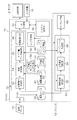
図1は本発明の実施形態に係るインクジェット印刷システムの構成例を示すブロック図である。インクジェット印刷システム10は、コンピュータ本体(以下「PC」と表記する。)12、モニタ14、入力装置16、及びプリンタ18を含んで構成される。PC12は、画像データを管理する機能、画像データを処理する機能、画像処理パラメータを管理する機能を有する。すなわち、PC12は、画像データ管理手段、画像データ処理手段、画像処理パラメータ管理手段として機能する。また、PC12はプリンタ18を制御する機能を有し、プリンタ制御手段として機能する。
<Configuration example of inkjet printing system>
FIG. 1 is a block diagram illustrating a configuration example of an inkjet printing system according to an embodiment of the present invention. The
PC12にはモニタ14及び入力装置16が接続されており、モニタ14及び入力装置16はユーザーインターフェース(UI)として機能する。入力装置16は、キーボード、マウス、タッチパネル、トラックボールなど、各種の手段を採用することができ、これらの適宜の組み合わせであってもよい。本例では入力装置16として、キーボードとマウスが用いられる。オペレータは、モニタ14の画面に表示される内容を見ながら入力装置16を使って各種情報の入力を行うことができ、プリンタ18を操作することができる。また、モニタ14を通じてシステムの状態等を把握(確認)することが可能である。
A monitor 14 and an
PC12は、画像データ20を取り込むための画像入力インターフェース部22と、取り込んだ画像データを保存する画像データ格納手段としてのデータベース(以下、「画像データDB」という。)24と、画像データを処理する画像データ処理部30と、階調変換用のルックアップテーブル(以下、「階調変換LUT」という。)を格納しておくデータベース(以下、「階調変換LUTDB」という。)40と、ムラ補正用のルックアップテーブル(以下、「ムラ補正LUT」という。)を格納しておくデータベース(以下、「ムラ補正LUTDB」という。)42と、ハーフトーン処理のパラメータを格納してデータベース(以下、「ハーフトーンDB」という。)44と、システムの全体的な制御を司るシステム制御部50と、ユーザーインターフェース(UI)制御部52とを備える。
The PC 12 processes an image
画像データ処理部30は、インク使用量の評価演算を担う処理部であり、画像縮小処理部32、画像変換部34、インク量データ算出部36及び画像解析部38を含む。この画像データ処理部30における処理内容の詳細は後述する。
The image
また、PC12は、テストパターンの読取結果からノズル単位のムラ補正LUTを作成する信号処理を行うLUT生成部54を備えるとともに、画像縮小処理部32で生成された縮小画像に対するムラ補正処理に相当する信号補正に適用されるルックアップテーブル(以下「ムラ補正サムネイルLUT」という。)をムラ補正LUTから生成するムラ補正サムネイルLUT生成部56を備える。なお、図1に示したPC12内の各部(符号22〜56の各要素)は、PC12のハードウエア又はソフトウェア、若しくはこれらの組み合わせによって構成される。
The PC 12 includes an LUT generation unit 54 that performs signal processing for creating a nozzle unit unevenness correction LUT from the test pattern reading result, and corresponds to unevenness correction processing for the reduced image generated by the image
LUT生成部54は、システム制御部50からの制御信号やUI制御部52から与えられる指令信号(操作信号)にしたがい、階調変換LUT、ムラ補正LUT、ハーフトーンテーブルなどのデータを生成する。
The LUT generation unit 54 generates data such as a gradation conversion LUT, an unevenness correction LUT, and a halftone table in accordance with a control signal from the system control unit 50 and a command signal (operation signal) given from the
ムラ補正サムネイルLUT生成部56は、ムラ補正LUTDB42に格納されているムラ補正LUTのデータから、インク使用量の評価演算に適用するムラ補正サムネイルLUTを生成する演算部である。生成されたムラ補正サムネイルLUTは、画像データ処理部30内の画像変換部34が参照するメモリ(不図示)にセットされる。
The unevenness correction thumbnail LUT generation unit 56 is an arithmetic unit that generates an unevenness correction thumbnail LUT to be applied to an ink usage amount evaluation calculation from the unevenness correction LUT data stored in the unevenness correction LUTDB 42. The generated unevenness correction thumbnail LUT is set in a memory (not shown) to which the
PC12内のシステム制御部50は、LUT生成部54やムラ補正サムネイルLUT生成部56並びに画像データ処理部30など各処理部における演算の制御を行うとともに、UI制御部52と連携してモニタ14の表示制御や入力装置16からの入力指令に対応した制御を行う。また、システム制御部50はプリンタ18のイメージプロセスボード60に信号を与え、プリンタ18の動作を制御する。
The system control unit 50 in the
画像データ20の入力部として機能する画像入力インターフェース部22は、有線又は無線の通信インターフェース部を採用してもよいし、メモリカードなどの外部記憶媒体(リムーバブルディスク)の読み書きを行うメディアインターフェース部を採用してもよく、これらの組み合わせであってもよい。
The image
画像入力インターフェース部22を介してPC12に入力された画像データ20は、画像データDB24に登録される。モニタ14には、画像データDB24に登録されている画像データの一覧を表示させることができる。オペレータはモニタ14の表示を見ながら入力装置16を操作することにより、対象となる画像データをプリントするか否かを指定することができる。また、オペレータは、画像データDB24に登録されている各画像データに対して、モニタ14と入力装置16を通じてプリント条件(例えば、用紙の種類、サイズ、枚数、カラー/白黒、色補正、濃淡補正など)を指定することできる。
The
プリント条件には、上記例示した項目の他に、階調変換LUTDB40、ムラ補正LUTDB42、ハーフトーンDB44の各パラメータの適切なデータが含まれる。印刷対象となる各画像データに対し、用紙種やサイズなど指定された条件に合わせて各データベース(40〜44)から適切なデータが選択され、これら情報を含むプリント条件のデータが各画像データに割り付けられる。
In addition to the items exemplified above, the print conditions include appropriate data for each parameter of the
画像データDB24に登録された画像データの一覧からプリントしたい画像データを選択し、プリント実行を指示すると、当該選択に係る画像データがPC12内の画像データDB24からプリンタ18に転送される。また、プリンタ18内のイメージプロセスボード60に対してプリント条件に対応したパラメータがセットされる。
When image data to be printed is selected from a list of image data registered in the
プリンタ18は、PC12から受信した画像データをマーキング信号に変換する信号処理を行うイメージプロセスボード60と、マーキング信号にしたがって印刷を実行するマーキング部68とを備える。イメージプロセスボード60は、階調変換処理部62、ムラ補正処理部64、ハーフトーン処理部66を含み、入力される画像データに対して階調変換処理、ムラ補正処理、ハーフトーン処理を施し、マーキング信号を生成する。イメージプロセスボード60に入力された画像データは、各処理部(62,64,66)による処理を経てマーキング部68により描画される。
The printer 18 includes an
階調変換処理部62は、マーキング部68で画像形成するときに、全体的にどのくらいの色の濃さで描画するかという、濃度階調の特性を決める処理を行う。階調変換処理部62は、プリンタ18で規定された発色特性になるように画像データを変換する。例えば、階調変換処理部62は、階調変換LUTにしたがい、CMYK信号をC’M’Y’K’信号に変換したり、C信号、M信号、Y信号、K信号の各信号を色別に、C’信号、M’信号、Y’信号、K’信号に変換したりする。
The gradation
階調変換処理部62による信号変換は、PC12内の階調変換LUTDB40に格納されているルックアップテーブル(「第1LUT」に相当、以下「階調変換LUT」という。)を参照して変換関係を定める。階調変換LUTDB40には、プリントする用紙(記録媒体)の種類毎に最適化された複数のLUTが格納されており、使用する用紙に合わせて適切なLUTが参照される。このような階調変換LUTは、インクの色毎に用意されている。本例の場合、CMYKの各色について、それぞれ階調変換LUTが設けられる。
The signal conversion by the gradation
プリントの実行指示が入力されると、その印刷条件に合致した階調変換LUTが自動的に選択され、プリンタ18の階調変換処理部62にセットされる。また、入力装置16からLUTの選択、変更、修正等の指示を入力することにより、所望のLUTに設定することができる。
When a print execution instruction is input, a tone conversion LUT that matches the printing conditions is automatically selected and set in the tone
ムラ補正処理部64は、マーキング部68を構成するインクジェットヘッドの各ノズルからある一定の階調値の入力信号によってインク吐出を行ったときに、階調変換処理部62で規定された濃度が記録媒体上の全面で均一濃度になるように、各ノズルの出力濃度(インク吐出量)を補正する処理部である。インクジェットヘッドは、ノズルによって吐出特性にばらつきがあり、吐出液滴量が必ずしも均一ではない。このようなノズル毎の吐出性能のばらつきに起因する出力濃度ムラをノズル単位で補正するためにムラ補正処理部64にて信号変換が行われる。すなわち、ムラ補正処理部64は、マーキング部68を構成するインクジェットヘッドにおける複数のインク吐出用ノズルのインク吐出量が、ヘッド内並びにヘッド間で所定の許容範囲内となり、画像面内で色ムラがなくなるように、各ノズルの吐出量を補正すべく画像信号を変換する。
The unevenness
例えば、CMYK信号をC”M”Y”K”信号に変換したり、C’信号、M’信号、Y’信号、K’信号の各信号を色別に、C”信号、M”信号、Y”信号、K”信号に変換したりする。この変換処理は、PC12内のムラ補正LUTDB42に格納されているLUT(「第2LUT」に相当、以下「ムラ補正LUT」という。)を参照して変換関係を定める。ムラ補正LUTDB42には、プリントする用紙の種類毎(紙種毎)に最適化された複数種類のムラ補正LUTが格納されており、使用する用紙に合わせて適切なLUTが参照される。
For example, the CMYK signal is converted into a C ″ M ″ Y ″ K ″ signal, or the C ′ signal, the M ′ signal, the Y ′ signal, and the K ′ signal are classified according to color by the C ″ signal, the M ″ signal, and the Y signal. Or converted into a “signal, K” signal. In this conversion process, a conversion relationship is determined with reference to an LUT stored in the
ハーフトーン処理部66は、多階調(例えば、1色当たり8ビット256階調)の画像信号を画素単位で、インク吐出する/しないの2値、若しくは、インク径(滴サイズ)が複数選択できる場合はどの滴種を吐出するかの多値の信号に変換する。一般的には、M値(Mは3以上の整数)の多階調画像データをN値(Nは2以上M未満の整数)のデータに変換する処理を行う。ハーフトーン処理には、ディザ法、誤差拡散法、濃度パターン法など、を適用できる。
The
本例のマーキング部68は、大滴、中滴、小滴の3種類の滴サイズを打ち分けることができるものとする。この場合、ハーフトーン処理部66は、ムラ補正処理後の多階調(例えば256階調)のデータから、「大滴インクを吐出する」、「中滴インクを吐出する」、「小滴インクを吐出する」、「吐出しない」の4値の信号に変換する。ハーフトーン処理部66における信号変換は、PC12内のハーフトーンDB44に格納されたテーブル(ハーフトーンテーブル)を参照して変換関係を決める。
It is assumed that the marking unit 68 of this example can sort three types of droplet sizes, large droplets, medium droplets, and small droplets. In this case, the
ハーフトーンテーブルは、大中小の各サイズのドットが単位面積あたりにどのような割合(比率)で用いられるかを規定したテーブルであり、入力信号の大きさに対応して各ドットサイズのドット比率(ドットサイズ別比率)が定められている。ハーフトーンDB44には、複数種類のハーフトーンテーブルが格納されており、プリント時にいずれかのテーブルが選択される。
The halftone table is a table that defines what ratio (ratio) of large, medium, and small dots is used per unit area. The dot ratio of each dot size corresponds to the size of the input signal. (Dot size ratio) is defined. The
ハーフトーン処理部66で生成された多値の信号(本例の場合4値のマーキング信号)は、マーキング部68に送られ、対応するノズルの吐出エネルギー発生素子(例えば、圧電素子や発熱素子)の駆動制御に用いられる。すなわち、この4値の信号にしたがってマーキング部68における各ノズルのインク吐出の制御が行われる。大滴インクによって記録媒体上に大ドットが記録され、中滴インクによって記録媒体上に中ドットが記録され、小滴インクによって記録媒体上に小ドットが記録される。こうして、記録媒体上に形成するインクドットの配置による面積階調によって多階調を再現する。
The multi-value signal (four-level marking signal in this example) generated by the
マーキング部68は、液体吐出ヘッドとしてのインクジェットヘッドを含んで構成される。本実施形態では、シアン(C)、マゼンタ(M)、イエロー(Y)、黒(K)の4色のインクを用いるものとし、各色のインクを吐出する手段として、色別にインクジェットヘッドを備える場合を説明する。ただし、インク色や色数の組み合わせについては本実施形態に限定されない。 The marking unit 68 includes an ink jet head as a liquid discharge head. In the present embodiment, four color inks of cyan (C), magenta (M), yellow (Y), and black (K) are used, and an ink jet head is provided for each color as means for ejecting each color ink. Will be explained. However, the combination of the ink color and the number of colors is not limited to this embodiment.
本例のインクジェット印刷システム10は、シングルパス方式で画像を記録するシステムである。すなわち、各色のインクジェットヘッドに対して記録媒体を相対的に移動させる動作を1回行うだけで(1回の副走査で)、記録媒体の画像形成領域に所定記録解像度(例えば、1200dpi)の画像を記録することができる。各ヘッドのインク吐出面(ノズル面)には、用紙の画像形成領域の最大幅に対応する長さにわたってインク吐出用のノズルが複数配列されている。インク吐出面に多数のノズルを二次元的に配列させる構成によって、高記録解像度を実現できる。
The
二次元ノズル配列を有するインクジェットヘッドの場合、当該二次元ノズル配列における各ノズルを媒体搬送方向(「副走査方向」に相当)と直交する方向(「主走査方向」に相当)に沿って並ぶように投影(正射影)した投影ノズル列は、主走査方向(媒体幅方向)について、記録解像度を達成するノズル密度でノズルが概ね等間隔で並ぶ一列のノズル列と等価なものと考えることができる。「概ね等間隔」とは、インクジェット印刷システムで記録可能な打滴点として実質的に等間隔であることを意味している。例えば、製造上の誤差や着弾干渉による媒体上での液滴の移動を考慮して僅かに間隔を異ならせたものなどが含まれている場合も「等間隔」の概念に含まれる。投影ノズル列(「実質的なノズル列」ともいう。)を考慮すると、主走査方向に沿って並ぶ投影ノズルの並び順に、ノズル位置(ノズル番号)を対応付けることができる。以下の説明で「ノズル位置」という場合、この実質的なノズル列におけるノズルの位置を指す。 In the case of an inkjet head having a two-dimensional nozzle array, the nozzles in the two-dimensional nozzle array are arranged along a direction (corresponding to “main scanning direction”) orthogonal to the medium transport direction (corresponding to “sub-scanning direction”). The projected nozzle row projected (orthographically projected) on the main scanning direction (medium width direction) can be considered to be equivalent to a single nozzle row in which the nozzles are arranged at substantially equal intervals at a nozzle density that achieves recording resolution. . The “substantially equidistant” means that the droplet ejection points that can be recorded by the ink jet printing system are substantially equidistant. For example, the concept of “equally spaced” also includes cases where the intervals are slightly different in consideration of manufacturing errors and movement of droplets on the medium due to landing interference. Considering projection nozzle rows (also referred to as “substantial nozzle rows”), nozzle positions (nozzle numbers) can be associated with the order of projection nozzles arranged along the main scanning direction. In the following description, “nozzle position” refers to the position of the nozzle in this substantial nozzle row.
<PC12内における画像データ処理部30の説明>
画像データ処理部30は、画像データを印刷する前に、予め当該画像データの印刷に使用されるインク量を計算し、用紙搬送上問題となるレベルのコックリングの発生が予測されるインク量の閾値(許容量の上限を示す規定値)を超えているかどうかを評価判断する処理部である。画像データ処理部30によるインク量の評価(予測)した結果、所定の閾値を超えている場合は、UI制御部52を介してモニタ14上にその判断結果を表示させる。この評価結果の表示と併せて、入力装置16からの指令入力を受け付け、階調変換LUT、ムラ補正LUT、ハーフトーンテーブルなどを変更(修正)する操作を促し、出力濃度(インク量)が規定値内になるように濃度を調整する。或いは、印刷ジョブの実行の取り消し(キャンセル)などの対応をとる。
<Description of Image
Before printing the image data, the image
印刷の対象として画像データDB24に登録された画像データは、描画インク使用量を計算するために、まず、画像縮小処理部32で縮小画像データに変換される。画像データDB24に登録される画像データ(入力された元の画像データ)の形式や画素数、解像度などの条件は特に限定はない。
Image data registered in the
例えば、入力された元の画像データは、原稿画像サイズ「B2」(JIS 規格の用紙寸法:728×515mm)の大きさのページ記述言語データとすることができる。また、入力画像データは、例えば、RGBの各色8ビット(24ビットカラー)の画像データでもよいし、インク色(例えば、CMYKの4色)に色変換された各色8ビットのデータでもよい。画像データDB24への登録画像の形式を整えるために、PC12内で画素数変換処理、色変換処理などの前処理を施してもよい。この場合、PC12内に画素数変換処理部、色変換処理部などを備える。
For example, the input original image data can be page description language data having a document image size “B2” (JIS standard paper size: 728 × 515 mm). The input image data may be, for example, 8-bit (24-bit color) image data of each RGB color, or 8-bit data of each color that is color-converted into ink colors (for example, 4 colors of CMYK). In order to adjust the format of the image registered in the
画像データDB24に登録される入力画像データは比較的大きなデータ量であるため、描画インク使用量の評価演算に際して、当該入力画像データを直接処理すると演算負荷が過大となる。したがって、本実施形態では演算の効率化の観点から、画像データを計算しやすいデータサイズに縮小する。すなわち、入力画像データから画像縮小処理部32にて所定の解像度の縮小画像(「サムネイル」と表記する場合がある。)を生成する。縮小画像の解像度について特に限定はないが、後述する画像解析部38のフィルタ処理に用いるフィルタのサイズとの関係で適当な解像度(画素数)に変換される。一例として、縮小画像における1画素の1辺が印刷用紙上の1mm程度の大きさに相当する解像度(数十dpi、例えば、25dpi程度)の画像に変換される。
Since the input image data registered in the
コックリングによる用紙変形(波打ち)の程度を判定する際に用いるフィルタ(空間フィルタ)のサイズは、例えば、1辺が1センチ程度の領域の画素範囲を演算対象とするものが用いられる。このような場合、縮小画像データの1画素当たりの面積は、概ねフィルタサイズの10分の1程度の大きさとすることが好ましい。 As the size of the filter (spatial filter) used when determining the degree of paper deformation (rippling) due to cockling, for example, a size that uses a pixel range of an area having one side of about 1 centimeter as a calculation target is used. In such a case, the area per pixel of the reduced image data is preferably about 1/10 of the filter size.
画像縮小処理部32により生成された縮小画像データは画像変換部34に送られ、この画像変換部34において階調変換処理とムラ補正処理に相当する画像変換処理が行われる。画像変換部34で行われる画像変換処理は、プリンタ18内のイメージプロセスボード60で実施される階調変換処理とムラ補正処理との組み合わせに対応した代替的な処理である。画像変換部34に適用される階調変換LUTは、プリンタ18内のイメージプロセスボード60における階調変換処理部62に適用されるLUTと同等のものであり、階調変換LUTDBから提供される。また、画像変換部34において階調変換LUTを使った変換に続き、ムラ補正サムネイルLUTを使ってムラ補正処理が行われる。
The reduced image data generated by the image
イメージプロセスボード60のムラ補正処理部64に適用されるムラ補正LUTはノズルごとにLUTが割り当てられており、データ量が大きいものであるため、縮小画像データに対する演算に必要なデータに加工/編集したムラ補正サムネイルLUTを作り、このムラ補正サムネイルLUTを画像変換部34に適用する。
The unevenness correction LUT applied to the unevenness
なお、ここでは、画像変換部34にて階調変換LUTを用いた階調変換処理を行った後に、ムラ補正サムネイルLUTを用いたムラ補正処理を行うという段階的な処理を説明したが、このような2段階の処理に限定されない。画像変換部34の演算に際して階調変換LUTとムラ補正サムネイルLUTとを統合した1つのLUTを用い、1回の変換演算によって階調変換とムラ補正を含んだ変換結果を得ることも可能である。このような一括変換の処理についても、階調変換LUTとムラ補正サムネイルLUTを適用した画像変換の処理に該当する。
Here, a step-by-step process has been described in which the
画像変換部34で変換された縮小画像データは、インク量データ算出部36にてインク量分布データに変換される。インク量データ算出部36は縮小画像データの各画素の信号値をハーフトーンのドット配置で再現する際のドットサイズ別の比率と、各ドットサイズに対応したインク滴量の情報から1画素あたりのインク量を計算する。
The reduced image data converted by the
ハーフトーンDB44には画素の信号値に応じたドットサイズ別比率の情報と、ドットサイズ(滴サイズ)ごとのインク滴量の情報が格納されている。インク量データ算出部36はハーフトーンDB44からこれらの情報を取得し、縮小画像データの1画素に相当する範囲ごとのインク量を求め、そのインク量を画素の座標に割り付けて、分布データを得る。また、インク量データ算出部36は、CMYKのインク色別に求めたインク量の分布データを全色分加算し、縮小画像の全体(1面)のインク量分布データを生成する。
The
インク量データ算出部36で生成された縮小画像のインク量分布データは画像解析部38に送られ、画像解析部38にてフィルタ処理された後、印刷画像上で規定値以上のインク量となる場所が存在するか否かの判定が行われる。規定値以上のインク量分布がある場合は、対象の画像データをプリントするとインク量が規定値を超えており、プリント時に不具合が発生することがオペレータにわかるように、その旨をモニタ14に表示する。
The ink amount distribution data of the reduced image generated by the ink amount
その一方、画像解析部38における判定の結果、規定値を超えるインク量分布がなければ、当該画像データをプリントしても特段問題はないため、特別のモニタ表示などはせずに、処理を完了する。なお、規定値を超えるインク量分布がない場合にプリントOKである旨を明示的にオペレータに伝える情報をモニタ14に表示させてもよい。
On the other hand, if there is no ink amount distribution exceeding the specified value as a result of the determination in the
図2は、PC12における信号処理の流れを示すフローチャートである。まず、PC12に画像データを入力する(ステップS11)。入力された画像データが画像データDBに登録された後、又は、画像データDBに登録する処理と並行して、当該画像データから縮小画像データを生成する(ステップS12)。図1で説明した画像縮小処理部32にて縮小画像データが生成される。
FIG. 2 is a flowchart showing the flow of signal processing in the
縮小画像データの1画素あたりの解像度は、画像解析部38のフィルタ処理で必要なサイズから決められたサイズに対応した解像度を定義し、その解像度になるように縮小処理をする。縮小画像データを生成するための縮小処理方法は、間引き処理など、いくつかの方法があるが、使用インク量の評価演算並びに判定の精度を高める方法として、入力画像データ上で縮小画像の1画素あたりの面積に相当する範囲を平均化し、そのデータを縮小画像の1画素として割り当てる方法が望ましい。
As the resolution per pixel of the reduced image data, a resolution corresponding to the size determined from the size necessary for the filter processing of the
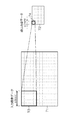
図3は画像縮小処理の一例を示す説明図である。図3の左側が画像縮小処理前の元の入力画像データを示しており、図3の右側が画像縮小処理後の縮小画像データを示している。図3では図示の便宜上、画素の数を減じて描いている。図3の左側に示した入力画像データにおいて、点線で示した格子の1セル(符号71)が入力画像データの1画素を表している。また、図3の右側に示した縮小画像データにおいて点線で示した格子の1セル(符号72)が縮小画像データの1画素を表している。 FIG. 3 is an explanatory diagram showing an example of image reduction processing. The left side of FIG. 3 shows the original input image data before the image reduction process, and the right side of FIG. 3 shows the reduced image data after the image reduction process. In FIG. 3, for the convenience of illustration, the number of pixels is reduced. In the input image data shown on the left side of FIG. 3, one cell (reference numeral 71) of a grid indicated by a dotted line represents one pixel of the input image data. Further, in the reduced image data shown on the right side of FIG. 3, one cell (reference numeral 72) of the lattice indicated by the dotted line represents one pixel of the reduced image data.
図3では、入力画像データにおける一定の画素領域(符号73の太線で囲んだ5×5=25画素の範囲を例示)が縮小画像データの1画素(図3において符号74の太線で囲んだ範囲)に対応している。図3に示した縮小画像データの1画素は、印刷用紙上で1辺がaミリメートル(mm)の正方形領域(amm×ammの矩形範囲)に相当しており(ただし、aは任意の正数で表される定数)、当該1画素の範囲内に属する元の入力画像データの画素領域について入力画像データの信号値を平均化処理し、その平均値を縮小画像の1画素の値(画素値)とする。つまり、図3の符号73の太線で囲んだ25画素の平均値が縮小画像データにおける符号74の太線で囲んだ1画素の信号値として割り当てられる。入力画像データの全体について、同様の平均化処理が行われ、縮小画像データが生成される。こうすると、元の入力画像における一定範囲の平均的な値が縮小画像の1画素に入るので、インク量の情報としては保存される。したがって、インク量の評価計算において精度の高い計算結果が得られる。なお、図3では、図示の都合上、縮小率を1/25として例示しているが、実際の縮小率はさらに小さく、例えば、元画像1200dpiから25dpi程度に大幅にデータ量が削減される。
In FIG. 3, a certain pixel region (an example of a range of 5 × 5 = 25 pixels surrounded by a bold line 73) in the input image data is one pixel of a reduced image data (a range surrounded by a
また、精度を出す別の方法として、入力画像データ上で縮小画像の1画素あたりの面積に相当する範囲の画素値を加算し、そのデータ加算値から縮小画像の信号値に変換するテーブルを通して1画素に割り当てる方法も望ましい。この場合、データ加算値sに対して縮小画像の信号値jを割り当てるための対応関係を規定したテーブルを予め用意しておき、このテーブルにしたがって、データ加算値sから縮小画像の信号値jに変換して画素に割り当てる。このような方法を採用しても、縮小処理前の入力画像データの信号値の情報が平均的に保存されるため、精度の高いインク量計算が可能である。 Further, as another method for improving the accuracy, a pixel value in a range corresponding to the area per pixel of the reduced image is added to the input image data, and 1 through a table that converts the data addition value into a signal value of the reduced image. A method of assigning to pixels is also desirable. In this case, a table defining a correspondence relationship for assigning the reduced image signal value j to the data addition value s is prepared in advance, and from the data addition value s to the reduced image signal value j according to this table. Convert and assign to pixels. Even if such a method is adopted, the information of the signal value of the input image data before the reduction process is stored on average, so that it is possible to calculate the ink amount with high accuracy.
また、別の方法として、元の入力画像データの所定画素領域内の信号値から代表値を定め、この代表値を縮小画像データの1画素の信号値に当てはめるという方法もある。代表値の決定に際しては、平均値の他、中央値(メジアン)や最頻値などを用いることができる。また、ヒストグラムから適当な代表値を決定してもよいし、最大値や最小値などを除外した範囲から代表値を決定してもよく、或いはまた、信号値分布の上位数%のところの平均値を代表値とするなど、統計演算上の工夫を適宜組み合わせてもよい。 As another method, there is a method in which a representative value is determined from a signal value in a predetermined pixel area of the original input image data, and this representative value is applied to the signal value of one pixel of the reduced image data. In determining the representative value, a median (median) or mode value can be used in addition to the average value. In addition, an appropriate representative value may be determined from the histogram, a representative value may be determined from a range excluding the maximum value and the minimum value, or the average of the upper few% of the signal value distribution. You may combine suitably the device on statistical calculation, such as making a value into a representative value.
画像縮小処理部32にて生成する縮小画像データは、その後の処理工程で(インク量データ算出部36にて)インク量分布データへ変換したときに必要なインク量分解能を保つために、縮小画像データの信号の深度(量子化する数値の範囲)は16ビット以上であることが望ましい。
The reduced image data generated by the image
縮小処理前の入力画像データの信号の深度(階調数)は、例えば、各色8ビット(256階調)とする。画像縮小処理部32にて、画像データの画素数を減らす処理を行う一方、各画素の信号の深度を16ビット化する。こうして、画像縮小処理部32にて生成された縮小画像データは、画像変換部34へと送られ、次に階調変換処理される。
The depth (number of gradations) of the input image data signal before the reduction process is, for example, 8 bits (256 gradations) for each color. The image
画像変換部34では、前半で画像データ全面に同じLUT(階調変換LUT)を使って変換する階調変換処理を行い、後半でムラ補正処理を行う(図2のステップS13)。
The
階調変換LUTを使った変換処理は、全体の濃度特性を決める処理である。この階調変換処理は、各信号の変換関係を決める一次元LUT(1D−LUT)を使う方法と、複数の色信号の組み合わせに対応した変換関係を決める多次元のn次元LUT(nD−LUT)を使う方法がある。 The conversion process using the gradation conversion LUT is a process for determining the overall density characteristics. This gradation conversion processing includes a method using a one-dimensional LUT (1D-LUT) for determining the conversion relationship of each signal and a multi-dimensional n-dimensional LUT (nD-LUT) for determining a conversion relationship corresponding to a combination of a plurality of color signals. ).
画像変換部34におけるムラ補正処理は、ノズル間の出力濃度のばらつきを補正する処理に対応しており、縮小画像の座標のうちノズル配列に対応した座標に対して、その座標に対応する位置のLUTをムラ補正サムネイルLUTから選択し、処理する。なお、縮小画像データの画素の位置と、各画素の面積に対応したノズルの範囲との対応関係は予め把握されており、縮小画像データのある画素の面積に対応する領域の描画を担うノズルの範囲は既知の情報としてPC12内に保持している。
The unevenness correction process in the
ムラ補正サムネイルLUTは、ムラ補正LUTDB42に格納されている各ノズルに割り当てられているムラ補正LUTから、縮小画像の1画素あたりの幅に対応するLUTを1つのLUTに編集したものである。 The unevenness correction thumbnail LUT is obtained by editing the LUT corresponding to the width per pixel of the reduced image into one LUT from the unevenness correction LUT assigned to each nozzle stored in the unevenness correction LUTDB42.
ムラ補正サムネイルLUT生成部56にてムラ補正サムネイルLUTを生成する1つの方法として、ノズル単位で規定されているムラ補正LUTから縮小画像の1画素あたりの幅に対応するLUTを平均化して縮小画像の1画素に対応するLUTを作成する。この方法は一例であり、ムラ補正LUTから縮小画像の解像度に応じてノズル並び方向の一定幅ごとに1つのLUTを対応させるムラ補正サムネイルLUTの作成方法は上記の例に限らない。 As one method for generating the unevenness correction thumbnail LUT by the unevenness correction thumbnail LUT generation unit 56, the reduced image is obtained by averaging the LUT corresponding to the width per pixel of the reduced image from the unevenness correction LUT defined for each nozzle. A LUT corresponding to one pixel is created. This method is an example, and the method of creating the unevenness correction thumbnail LUT in which one LUT is associated with each fixed width in the nozzle arrangement direction according to the resolution of the reduced image from the unevenness correction LUT is not limited to the above example.
ムラ補正サムネイルLUTを作成する他の方法として、ムラ補正LUTを基に、縮小画像の画素の1画素あたりの幅に対応するLUTの範囲の中で一番大きな値を持つLUTを縮小画像の1画素に対応するLUTにするなどの方法を採用してもよい。ムラ補正サムネイルLUTの作成方法については、後段の画像解析部38で用いるフィルタやインク量判定用の閾値(規定値)等との関係で適切な形態が決定される。
As another method of creating the unevenness correction thumbnail LUT, based on the unevenness correction LUT, the LUT having the largest value in the range of the LUT corresponding to the width per pixel of the reduced image is set to 1 of the reduced image. A method such as making an LUT corresponding to a pixel may be adopted. As for the method of creating the unevenness correction thumbnail LUT, an appropriate form is determined in relation to a filter used in the subsequent
ムラ補正サムネイルLUTを生成するタイミングについては、特に限定されないが、例えば、プリント上でムラ調整を実行し、ムラ補正LUTが新たに生成された直後にムラ補正サムネイルLUTを生成し、画像変換部34で処理が可能な領域に当該最新のムラ補正サムネイルLUTのデータをセットすることが好ましい。
Although the timing for generating the unevenness correction thumbnail LUT is not particularly limited, for example, unevenness adjustment is performed on the print, the unevenness correction thumbnail LUT is generated immediately after the unevenness correction LUT is newly generated, and the
オペレータが印刷状態を監視して、必要に応じて入力装置16から「画像調整」の指令を入力すると、システムは調整処理の動作に入り、ムラ補正用のテストパターンの印刷とその印刷結果の読み取りが行われ、その読み取り情報からムラ補正LUTが作成されて、ムラ補正LUTDB42の情報が更新される。その直後に、当該最新のムラ補正LUTからムラ補正サムネイルLUTも一緒に作成し、当該最新のムラ補正サムネイルLUTを所定のメモリ領域(当該テーブルを参照する記憶保存場所)にセットしておくことが好ましい。このようにムラ補正LUTの更新と一緒にムラ補正サムネイルLUTも常に最新のデータに更新しておくことで、演算処理時間を短縮することが可能である。
When the operator monitors the printing state and inputs an “image adjustment” command from the
また、ムラ補正LUTの生成と同時に(ムラ補正LUTの生成直後に)ムラ補正サムネイルLUTを生成する構成に限らず、インク使用量の評価演算の必要に応じて随時、ムラ補正LUTから作成してもよい。 Further, the present invention is not limited to the configuration for generating the unevenness correction thumbnail LUT at the same time as the generation of the unevenness correction LUT (immediately after the generation of the unevenness correction LUT). Also good.
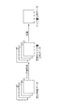
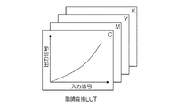
図4は、画像変換部34における画像変換処理の内容を示した概念図である。CMYKの色別の縮小画像データは、それぞれ色別の階調変換LUTを用いて階調変換された後、色別のムラ補正サムネイルLUTを用いてムラ補正処理が行われる。図4では、階調変換LUTとして色別の一次元LUTを例示した。
FIG. 4 is a conceptual diagram showing the contents of the image conversion process in the
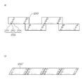
各色のムラ補正サムネイルLUTは、ノズル列方向に複数のテーブルを含んでいる。ノズル列方向とは、インクジェットヘッドの複数のノズルが所定の記録解像度を達成するように実質的に並ぶ方向である。図5に示すように、縮小画像データの横方向(x方向)と縦方向(y方向)に座標軸(x軸、y軸)を導入し、xy平面上で各画素の位置を(x,y)の座標で表すとき、例えば、x方向に沿ってインクジェットヘッドのノズルが並んでいるものとする。この場合、縮小画像データのx方向の各画素位置に対応して、1画素あたりに1つのLUTが対応付けられた複数のテーブルを持つ。 Each color unevenness correction thumbnail LUT includes a plurality of tables in the nozzle row direction. The nozzle row direction is a direction in which a plurality of nozzles of the inkjet head are substantially aligned so as to achieve a predetermined recording resolution. As shown in FIG. 5, coordinate axes (x axis, y axis) are introduced in the horizontal direction (x direction) and vertical direction (y direction) of the reduced image data, and the position of each pixel on the xy plane is (x, y). ), For example, it is assumed that the nozzles of the inkjet head are arranged along the x direction. In this case, there is a plurality of tables in which one LUT is associated with each pixel corresponding to each pixel position in the x direction of the reduced image data.
つまり、ムラ補正サムネイルLUTは、画素位置(x)の関数として適用され、ノズル列方向(ここではx方向を例示)の単位で同じLUTのセットが適用される。縮小画像データの画素のx座標が同じであれば、y座標が異なる画素に対しても同じLUTが適用される。図5では、太線で囲んだ画素と同じx座標の画素列(y方向に並ぶ各画素)に対して、同じムラ補正サムネイルLUTが適用されることを示している。こうして、階調変換LUTとムラ補正サムネイルLUTを用いた変換処理が実施され、変換後の縮小画像データが得られる。 That is, the unevenness correction thumbnail LUT is applied as a function of the pixel position (x), and the same set of LUTs is applied in units of the nozzle row direction (here, the x direction is illustrated). If the x coordinates of the pixels of the reduced image data are the same, the same LUT is applied to pixels having different y coordinates. FIG. 5 shows that the same unevenness correction thumbnail LUT is applied to a pixel row having the same x coordinate as the pixels surrounded by a thick line (pixels arranged in the y direction). In this way, the conversion process using the gradation conversion LUT and the unevenness correction thumbnail LUT is performed, and converted reduced image data is obtained.
画像変換部34(図1参照)によって階調変換処理された変換後の縮小画像データは、インク量データ算出部36に送られ、当該縮小画像データからインク量分布データが作成される(図2のステップS14)。インク量データ算出部36では、ハーフトーンデータとインク滴量データを使ってインク量分布を生成する。処理の1つの方法として、縮小画像データに対応するハーフトーン処理されたときのインクドットサイズ別比率を求め、その比率に各インクドットサイズのインク滴量を積算した上で、各ドットサイズのインク滴量を加算し、各色に対応するインク量を求める。
The reduced image data after the gradation conversion processing by the image conversion unit 34 (see FIG. 1) is sent to the ink amount
このとき、縮小画像データを実際にハーフトーン処理するのではなく、縮小画像データの信号値に対してプリンタ18による階調再現時のインクドットサイズ別の比率データが関連付けられたテーブルが用意されており、このハーフトーンデータのテーブルから所定面積内のインクドットサイズ別比率が把握される。例えば、4値化したときの比率として、無ドット(余白、白抜き)が40%、小ドット30%、中ドット25%、大ドット5%という具合に、ある信号値jに対して、単位面積あたりの平均的なドットサイズ別の記録比率が特定される。 At this time, instead of actually performing halftone processing on the reduced image data, a table is prepared in which ratio data for each ink dot size at the time of gradation reproduction by the printer 18 is associated with the signal value of the reduced image data. Thus, the ratio by ink dot size within a predetermined area is obtained from the table of halftone data. For example, as a ratio in the case of quaternarization, a unit for a certain signal value j such as 40% of no dots (margins, whiteout), 30% of small dots, 25% of medium dots, and 5% of large dots. A recording ratio for each average dot size per area is specified.
このインクドットサイズ別比率に対して、各ドットサイズの1ドットあたりのインク滴量を掛けて、CMYKの信号別インク量分布データを得る。さらに、各色のインク量分布データを画素毎に加算して、縮小画像の1画素あたりのインク量を求める。このインク量データに座標を割り付け、インク量分布データにする。 CMYK signal-specific ink amount distribution data is obtained by multiplying the ink dot size ratio by the ink droplet amount per dot of each dot size. Further, the ink amount distribution data of each color is added for each pixel to obtain the ink amount per pixel of the reduced image. Coordinates are assigned to the ink amount data to form ink amount distribution data.
図6には、CMYKの各色の信号別縮小画像データから、信号別インク量分布データを作成し、これらを加算してインク量分布データを作成する手順を模式的に説明した図を示した。インク量分布データは、画像解析部38で必要なインク量分解能を保つために、信号の深度は16ビット以上を使うことが望ましい。
FIG. 6 schematically shows a procedure for creating ink amount distribution data for each signal from the reduced image data for each color of CMYK and adding them to create ink amount distribution data. In order to maintain the ink amount resolution required by the
こうして生成されたインク量分布データを基に、画像解析部38(図1参照)で規定値以上のインク量が使用されるかどうかの判定を行う。画像解析部38ではインク量分布データに対してフィルタ処理を行い(図2のステップS15)、一定面積のエリアごとのインク使用量が規定値以上となるか否かの判定を行う(図2のステップS16)。
Based on the ink amount distribution data thus generated, the image analysis unit 38 (see FIG. 1) determines whether or not the ink amount equal to or greater than the specified value is used. The
図7は、インク量分布データに対するフィルタ処理の説明図である。図7において、インク量分布データの複数画素領域に対してフィルタ(符号84)が適用される。ここでは、図示の都合上、y方向に並ぶ3画素の画素列範囲に及ぶフィルタ84を例示しているが、フィルタの種類やサイズは様々な形態があり得る。ここでは、y方向の1次元フィルタを例示したが、x方向の1次元フィルタであってもよいし、2次元フィルタであってもよい。
FIG. 7 is an explanatory diagram of the filter processing for the ink amount distribution data. In FIG. 7, a filter (reference numeral 84) is applied to a plurality of pixel regions of the ink amount distribution data. Here, for the sake of illustration, the
インク量分布データに対して所定のフィルタ84がx方向、y方向に演算対象の画素位置を変えて、繰り返し適用される。図7中のx方向に沿った矢印とy方向に沿った矢印は、フィルタ84がx方向とy方向にそれぞれ位置を変えながら、順次フィルタ処理が進められる様子を示している。フィルタ84のサイズは、インク使用量を評価する画像領域の大きさに対応して適宜の大きさに設計される。
A
この判定の結果、規定値以上のインク量エリアが存在する場合には、モニタ14の画面上に警告を表示する(ステップS17)。その一方、ステップS16の判定において規定値以上のインク量エリアが存在しなければ、ステップS17の警告表示を省略して処理を終了する。 If the result of this determination is that there is an ink amount area that exceeds the specified value, a warning is displayed on the screen of the monitor 14 (step S17). On the other hand, if there is no ink amount area greater than the specified value in the determination in step S16, the warning display in step S17 is omitted and the process is terminated.
一例として、コックリングに起因する通紙不良を防止するためのインク量判定について説明する。用紙に対する単位面積当りのインク量が増えると、用紙に水分が吸収されることにより用紙変形(コックリング)が発生し、これが原因で通紙不良(例えば、インクジェットヘッドのノズル面に用紙が接触するなどの問題)が発生する場合がある。このような通紙不良を防ぐことを主目的として、画像解析部38では、用紙上の一定エリア内に一定量(規定値)以上のインク量が使われる場所があるか否かの判定を行い、規定量以上のインク量となる場所が存在するとの判定結果が得られた場合は、通紙不良発生の可能性があることを警告するために警告判断演算子(例えば、警告表示の要否を制御するフラグ)をONにする処理を行う。
As an example, ink amount determination for preventing paper passing failure caused by cockling will be described. When the amount of ink per unit area with respect to the paper increases, the paper is deformed (cockling) due to the absorption of moisture into the paper, and this causes poor paper passing (for example, the paper contacts the nozzle surface of the inkjet head). Etc.) may occur. With the main purpose of preventing such a paper passing defect, the
この例の場合、一定エリアに相当するサイズのフィルタ84をインク量分布データ内のさまざまな場所に割り当て、規定量以上のインク量の値かどうかを確認する処理を行って、警告判断演算子のON/OFFを決める。規定値以上のインク量が使用されているかどうかを判定するインク量の閾値は、用紙の種類、大きさ、厚み、紙目、表裏面によって設定が変わる。また、閾値は1つの値に限らず、複数の評価指標から決定する方法もある。
In this example, the
コックリングと通紙不良の関係については、用紙上のある面積領域がどのくらいのインク量になると通紙不良の恐れがある(通紙保証できない)というインク量許容値が実験的にデータとして把握される。このような条件に基づいて、用紙の種類やインクジェットプリンタの機種ごとに、判定条件と閾値が定められる。 With regard to the relationship between cockling and poor paper passing, the ink amount tolerance that there is a risk of paper passing failure (passage guarantee cannot be guaranteed) will be experimentally grasped as data. The Based on such conditions, determination conditions and thresholds are determined for each type of paper and each type of inkjet printer.
図7で例示したように、1種類のフィルタ84について1つの閾値を定めておく構成を採用してもよいし、サイズ(面積)の異なる複数のフィルタを用い、各フィルタについてそれぞれ個別に閾値を定めておき、どれか1つでも閾値を超えるものがあったら全体としてNGと判定する、という態様も可能である。
As illustrated in FIG. 7, a configuration in which one threshold value is determined for one type of
画像解析部38による解析処理の結果、警告判断演算子がONとなる場合、モニタ14の画面上に警告を表示させる(図2のステップS17)。
When the warning determination operator is turned on as a result of the analysis processing by the
図8及び図9に表示画面の例を示した。PC12の画像データDB24に入力画像データを登録した直後に、画像データ処理部30によるインク使用量の評価演算を開始し、その判定結果をモニタ14のジョブ一覧に表示させる。図8に示す例では、インク使用量が規定値以上となると判定されたジョブに対して、ハイライト表示がなされるとともに、「NG」という警告文字が付される。警告表示の具体的な形態は図示の例に限定されないが、ここに例示したように、通紙不良が予想されるジョブについて、背景色や文字の色を異ならせたり、特定の文字や記号等による表示を付加するなど、他の正常印刷が可能なジョブ(OKジョブ)と明確に区別できるような差別化表示が行われる。
Examples of display screens are shown in FIGS. Immediately after the input image data is registered in the
或いはまた、図9に示したように、問題なく正常に印刷ができるジョブ群(警告が出ていないジョブ群)と、通紙不良が予想されるジョブ群(警告が出ているジョブ群)とをモニタ14の画面上で表示領域を明確に区別して表示させてもよい。図9では、画面の上段にOKジョブの表示が振り分けられ、画面の下段にNGジョブの表示が振り分けられている。なお、図8及び図9の例では、各画像に対応したジョブの一覧を文字表示する画面を示したが、各ジョブIDに代えて、又はこれと組み合わせて、印刷対象の画像内容を表示させてもよい。図8や図9で例示したようなモニタ表示により、オペレータは警告に係る画像データの印刷ジョブをキャンセルしたり、プリント条件を修正したりするなどの対処を行うことができる。 Alternatively, as shown in FIG. 9, a job group that can be printed normally without any problem (a job group that has not issued a warning), and a job group that is expected to have a paper passing failure (a job group that has issued a warning) May be displayed with the display area clearly distinguished on the screen of the monitor 14. In FIG. 9, the display of OK jobs is distributed in the upper part of the screen, and the display of NG jobs is distributed in the lower part of the screen. In the examples of FIGS. 8 and 9, the screen displaying the list of jobs corresponding to each image is shown, but the image content to be printed is displayed instead of or in combination with each job ID. May be. The monitor display as illustrated in FIGS. 8 and 9 allows the operator to take measures such as canceling the print job of the image data related to the warning or correcting the print conditions.
また、階調変換LUTやムラ補正LUTが更新されると、インク量分布の結果が変わるため、その都度、判定結果の更新が行われる。すなわち、本実施形態のシステムでは、階調変換LUTやムラ補正LUTが更新されると、その最新のテーブルに基づいてインク量分布データが再計算され、規定値以上のインク使用量となるか否かの判定の再判定が行われる。この判定結果にしたがいモニタ14の表示が更新される。 Further, when the tone conversion LUT and the unevenness correction LUT are updated, the result of the ink amount distribution changes, so that the determination result is updated each time. That is, in the system of the present embodiment, when the tone conversion LUT or the unevenness correction LUT is updated, the ink amount distribution data is recalculated based on the latest table, and whether or not the ink usage amount exceeds the specified value. This determination is re-determined. The display on the monitor 14 is updated according to the determination result.
こうして、常に最新の画像調整パタメータを反映させたインク量分布データが計算され、プリント品質に影響を与えるかどうかが判定される。これにより、精度の高い判定が可能である。 In this way, the ink amount distribution data that always reflects the latest image adjustment parameters is calculated, and it is determined whether the print quality is affected. Thereby, determination with high accuracy is possible.
上述の説明では通紙保証の観点からプリント品質の影響の有無を判定する例を説明したが、着弾位置ズレによる画質低下などの観点からプリント品質への影響の有無を判定することもできる。画像解析部38で適用するフィルタの形態と判定用の閾値の設定に応じて、様々な観点でプリント品質への影響を評価することができる。
In the above description, the example in which the presence or absence of the print quality is determined from the viewpoint of sheet passing guarantee has been described. However, the presence or absence of the influence on the print quality can also be determined from the viewpoint of image quality degradation due to landing position deviation. The influence on the print quality can be evaluated from various viewpoints according to the filter form applied by the
<イメージプロセスボード60における画像処理の説明>
ここで、プリンタ18内のイメージプロセスボード60における信号処理の具体例について、図10〜図13を用いて説明する。
<Description of Image Processing in
Here, a specific example of signal processing in the
図10は、イメージプロセスボード60の処理プロセスを示した説明図である。階調変換処理部62には、CMYKに色分離された多階調データが入力される。ここでは、マーキング部68における各インク色ごとの多階調画像データ(例えば、CMYKの4色に対応した色別の256階調画像データ)が与えられるものとする。
FIG. 10 is an explanatory diagram showing a processing process of the
なお、RGBフルカラー24ビット(各色8ビット)の画像データが入力される場合や、入力画像の解像度とインクジェット描画装置の出力解像度に差がある場合などには、公知の色変換処理、解像度変換処理が行われる。 In addition, when RGB full-color 24-bit image data (8 bits for each color) is input, or when there is a difference between the resolution of the input image and the output resolution of the inkjet drawing apparatus, a known color conversion process or resolution conversion process is performed. Is done.
階調変換処理部62には、CMYKの色別にテーブル(階調変換LUT)が適用され、入力信号をある目標の濃度階調となるように変換する。階調変換処理部62に入力されたCMYK信号は、色別の階調変換LUTによってC’M’Y’K’信号に変換される。
A table (gradation conversion LUT) is applied to the gradation
図11は、階調変換処理部62で用いられる階調変換LUTの概念図である。図11に示すように、階調変換LUTは、CMYKの各色信号別に設けられており、入力信号値を出力信号値に変換する入出力関係を定めたLUTである。階調変換LUTにしたがって変換された信号は、ムラ補正処理部64に入力される(図10参照)。
FIG. 11 is a conceptual diagram of a gradation conversion LUT used in the gradation
図12は、ムラ補正処理部64(図1、図10参照)における補正処理の概念図である。図12では、Cインク用のインクジェットヘッドについてノズル数を減らして描いているが、実際には各色ヘッドに備える全ノズルについて、各ノズルに対応してそれぞれ吐出補正LUTが存在している。図12中のi,i+1,・・・,i+4は、ノズル番号を表している。なお、ノズル番号iは、記録解像度によるドット列の形成が可能な実質的なノズル列の端からi=1,2,3・・・という具合に連続する整数の番号で各ノズルに付与することができ、ノズル番号によってノズルの位置を特定することができる。ノズル番号は、記録解像度で記録媒体上の打滴点(記録位置)を記録できるように複数のノズルが配列されたノズル配置における実質的なノズル列のノズル並び順を表す。 FIG. 12 is a conceptual diagram of correction processing in the unevenness correction processing unit 64 (see FIGS. 1 and 10). In FIG. 12, the ink jet head for C ink is drawn with a reduced number of nozzles, but in reality, for all nozzles provided in each color head, there is a discharge correction LUT corresponding to each nozzle. In FIG. 12, i, i + 1,..., I + 4 represent nozzle numbers. The nozzle number i is assigned to each nozzle by an integer number that is continuous such that i = 1, 2, 3,... The nozzle position can be specified by the nozzle number. The nozzle number represents the substantial nozzle arrangement order of the nozzle array in the nozzle arrangement in which a plurality of nozzles are arranged so that the droplet ejection point (recording position) on the recording medium can be recorded with the recording resolution.
図示のように、ノズル毎に入力信号値と出力信号値の変換関係を規定したLUTが存在し、これが全ノズル分集合したLUT群となっており、さらに、色別のヘッドの全ヘッドについて、同様のLUT群が存在する。 As shown in the figure, there is an LUT that defines the conversion relationship between the input signal value and the output signal value for each nozzle, and this is an LUT group that is aggregated for all nozzles. There are similar LUT groups.
ムラ補正処理部64(図1、図10参照)は、入力されるC’M’Y’K’データに対して、ムラ補正LUTを用いて、C”M”Y”K”データに変換する。なお、図1、図10では、説明の便宜上、階調変換処理とムラ補正処理とを段階的に行う例を示しているが、階調変換LUTとムラ補正LUTを合成して1つのLUTにまとめ、これらの変換処理を一括で行う演算方法を採用することができる。階調変換処理及びノズル吐出補正処理を経て生成された変換後の信号は、ハーフトーン処理部66に入力される。
The unevenness correction processing unit 64 (see FIGS. 1 and 10) converts the input C′M′Y′K ′ data into C “M” Y ”K” data using the unevenness correction LUT. . 1 and 10 show an example in which gradation conversion processing and unevenness correction processing are performed stepwise for convenience of explanation, but the gradation conversion LUT and unevenness correction LUT are combined into one LUT. In summary, it is possible to employ a calculation method that performs these conversion processes in a lump. The converted signal generated through the gradation conversion process and the nozzle discharge correction process is input to the
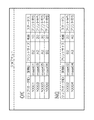
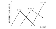
図13は、ハーフトーン処理部66(図1、図10参照)に適用されるハーフトーンテーブルの一例を示すものである。図13の横軸は入力信号を表し、縦軸は単位面積あたりにおける大中小のインクドットの記録割合(ドット比率)を示した量である。例えば、図13の縦軸は、最大で100画素のインク打滴できる領域(「単位面積」に相当)に、大中小のドットインクがそれぞれ何個ずつ打たれるかの割合を示した量である。入力信号値に対して、各種ドットをどのような比率で使用するかを定めたハーフトーンテーブルは複数種類用意され、プリント時にいずれかのテーブルが選択される。 FIG. 13 shows an example of a halftone table applied to the halftone processing unit 66 (see FIGS. 1 and 10). The horizontal axis in FIG. 13 represents the input signal, and the vertical axis represents the recording ratio (dot ratio) of large, medium, and small ink dots per unit area. For example, the vertical axis in FIG. 13 is an amount indicating the ratio of how many large, medium, and small dot inks are ejected in a region (corresponding to “unit area”) that can eject ink of 100 pixels at the maximum. is there. A plurality of types of halftone tables that determine the ratio of various dots to be used with respect to the input signal value are prepared, and one of the tables is selected during printing.
<ムラ補正LUTの生成方法の説明>
ムラ補正処理部64(図1、図10参照)に適用されるムラ補正LUTは、次のような手順で生成される。図14は、ムラ補正LUTの生成手順の一例を示したフローチャートである。ムラ補正LUTを作成する算出タイミングは任意であり、特に、限定されない。例えば、印刷ジョブを実行する前に、テストチャートを出力して補正値の算出を行う態様、所定枚数のプリントを実施するごとに1回というタイミングでテストチャートを出力して補正値の算出を行う態様、用紙の種類、用紙サイズを切り換えるタイミングでその印刷前にテストチャートを出力して補正値の算出を行う態様、画像出力毎に記録媒体の余白部にテストチャートを出力して補正値の算出を行う態様、或いは、定期メンテナンスやユーザーからの指示があったときに上記の補正値の算出を行う態様、などがあり得る。ムラ補正LUTのデータは適当なタイミングで更新される。
<Description of Generation Method of Unevenness Correction LUT>
The unevenness correction LUT applied to the unevenness correction processing unit 64 (see FIGS. 1 and 10) is generated by the following procedure. FIG. 14 is a flowchart illustrating an example of a procedure for generating the unevenness correction LUT. The calculation timing for creating the unevenness correction LUT is arbitrary and is not particularly limited. For example, a mode in which a correction value is calculated by outputting a test chart before executing a print job, and a correction value is calculated by outputting the test chart at a timing of once every time a predetermined number of prints are performed. A mode in which a correction value is calculated by outputting a test chart before printing at the timing of switching the mode, paper type, and paper size, and a correction value is calculated by outputting a test chart to the margin of the recording medium for each image output. There may be a mode in which the above correction value is calculated when there is a periodic maintenance or an instruction from the user. The data of the unevenness correction LUT is updated at an appropriate timing.
図14に示すムラ補正LUTの生成処理がスタートすると、まず、記録濃度分布の測定に用いるテストチャートの出力が行われる(ステップS60)。 When the unevenness correction LUT generation process shown in FIG. 14 is started, first, a test chart used for measurement of the recording density distribution is output (step S60).
図15は、記録媒体上に記録されるテストチャート(テストパターンと呼ぶ場合もある)の一例を示す図である。図15に示した濃度分布測定用テストチャート90は、階調値の異なる複数種類(ここでは8種類)の帯状のパターン90A〜90Hを含んで構成される。各帯状のパターン90A〜90Hは、媒体搬送方向に直交する媒体幅方向に沿って長い矩形形状となっている。媒体幅方向は、ラインヘッドによる実質的なノズル列の方向であり、各帯状のパターン90A〜90Hは、ノズル列の長さに対応する範囲で概ね均一の濃度で形成される。「概ね均一の濃度」とは、パターンの記録に際して、階調の指令値(設定値)として一定であることを意味している。一定の階調値の指令に基づいて描画されるパターンの濃度分布を測定することで、当該階調値に対応する各ノズルの吐出特性のばらつきを把握することができる。
FIG. 15 is a diagram illustrating an example of a test chart (sometimes referred to as a test pattern) recorded on a recording medium. The density distribution
本例では、媒体搬送方向の上流側から下流側に向かって(図15における下から上に向かって)順に、インク濃度が小さくなる配列順で濃度を異ならせたパターン90A〜90Hが形成されている例を示したが、パターンの配列順や帯状のパターンの数(濃度を変えるステップ数)は特に限定ない。各帯状のパターンを記録する設定階調値は適宜設定することができ、帯状のパターンの数も適宜設計できる。このようなテストチャート90は、CMYKの各ヘッドにより、色毎に形成される。また、1枚の記録媒体(用紙)92上に全てのパターン90A〜90Hを記録する態様に限らず、これら帯状のパターンを複数枚の記録媒体に分けて記録してもよい。
In this example,
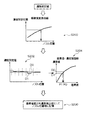
こうして記録媒体92上に形成されたテストチャート90は、オフラインスキャナー、或いは、インクジェット印刷システム10の用紙搬送経路中に設置された画像読取センサ(インラインセンサ)などの読取装置によって読み取られ、当該テストチャート90の読取データ(電子画像データ)が取得される。この読取データから、画像内の各位置における光学濃度(OD:Optical Density)値が求められ、各位置に対応するノズル毎の出力記録濃度(インク濃度)を示す出力濃度データが取得される(図14のステップS62)。このようにして求められる出力濃度データと、入力階調値の値とに基づいて、ノズル毎の吐出特性(記録濃度特性)を示す特性曲線が取得される。
The
図16は、あるノズルの吐出特性曲線の例を示したグラフである。横軸は入力画像データ(入力階調値)、縦軸は出力濃度を示している。図16中の曲線Gtは、テストチャートの読取結果から取得されたノズルの特性曲線を示している。図16中の破線で示した曲線Gaは、設計上想定される適正なインク吐出が行われる場合に得られる特性曲線(適正特性曲線)を表している。図16に示すように、実際のノズルの特性曲線Gtは、製造ばらつき、その他の要因により、適正特性曲線から多少ずれた曲線を描くのが通常であり、図16中の上下双方向矢印で示されるように、ノズル間で出力濃度値のばらつきが見られる。各ノズルの特性曲線Gtは、適正特性曲線Gaと比較され、その比較結果に応じて、対象ノズルの吐出制御に対する補正値のテーブル(吐出補正LUT、すなわちノズル毎のムラ補正LUT)が生成される(図14のステップS64)。 FIG. 16 is a graph showing an example of a discharge characteristic curve of a certain nozzle. The horizontal axis represents input image data (input gradation value), and the vertical axis represents output density. A curve Gt in FIG. 16 indicates a characteristic curve of the nozzle obtained from the reading result of the test chart. A curve Ga indicated by a broken line in FIG. 16 represents a characteristic curve (appropriate characteristic curve) obtained when proper ink ejection assumed in design is performed. As shown in FIG. 16, the actual nozzle characteristic curve Gt usually draws a curve slightly deviated from the appropriate characteristic curve due to manufacturing variations and other factors. As can be seen, there is a variation in the output density value among the nozzles. The characteristic curve Gt of each nozzle is compared with the appropriate characteristic curve Ga, and a correction value table (discharge correction LUT, that is, a non-uniformity correction LUT for each nozzle) is generated according to the comparison result. (Step S64 in FIG. 14).
こうして、全てのノズルについて吐出補正LUTが求められ、これら全ノズル分の吐出補正LUTがムラ補正LUTDB42(図1参照)に格納される(図14のステップS66)。なお、ノズルの特性曲線Gtと適正特性曲線Gaとの比較によって、そのノズルが不吐出ノズルであるか否か、或いは補正不能なレベルの吐出異常ノズルであるか否かの判断も可能である。また、いわゆる1オンnオフ型のラインパターンを含んだテストパターンなどを形成して、その読取結果から不吐出ノズルや吐出量異常、着弾位置誤差などを把握することも可能である。 In this way, the discharge correction LUT is obtained for all the nozzles, and the discharge correction LUT for all the nozzles is stored in the unevenness correction LUTDB 42 (see FIG. 1) (step S66 in FIG. 14). By comparing the nozzle characteristic curve Gt with the appropriate characteristic curve Ga, it is also possible to determine whether the nozzle is a non-ejection nozzle or an uncorrectable level ejection abnormal nozzle. It is also possible to form a test pattern including a so-called 1-on-n-off type line pattern and grasp the non-ejection nozzle, ejection amount abnormality, landing position error, etc. from the read result.
不吐出ノズル或いは補正不能な吐出異常ノズルについては、記録に使用することができない不良ノズルであるとして、画像記録時に吐出駆動させない扱いにしてもよい。このような不吐出化の処理を行う不良ノズルについては、対応するノズルの吐出補正LUTをムラ補正LUTDB42に保存しなくてもよい。
A non-ejection nozzle or an ejection abnormal nozzle that cannot be corrected may be treated as a defective nozzle that cannot be used for recording, and not ejected during image recording. For defective nozzles that perform such non-ejection processing, the ejection correction LUT of the corresponding nozzle does not have to be stored in the
<ノズル毎の吐出制御に対する補正値の算出方法の概要>
図17は、ノズル毎のムラ補正LUTを求める処理の一例を示す説明図である。図17のS200に示されるように、読取装置の画素位置(濃度測定位置)とノズル位置との対応関係を示す解像度変換曲線のテーブルデータが予めメモリに記憶されており、テストチャートの読取結果から、この解像度変換曲線にしたがって、テストチャートの読取データ(スキャン画像)における各測定濃度位置(例えば、400dpiの読取解像度による画素位置)が、インクジェットヘッドにおける対応ノズルの位置(例えば、1200dpiの記録解像度を実現するノズル列内のノズル位置)に変換される。
<Outline of correction value calculation method for discharge control for each nozzle>
FIG. 17 is an explanatory diagram illustrating an example of processing for obtaining the unevenness correction LUT for each nozzle. As shown in S200 of FIG. 17, table data of a resolution conversion curve indicating the correspondence between the pixel position (density measurement position) of the reading device and the nozzle position is stored in advance in the memory. According to this resolution conversion curve, each measured density position (for example, a pixel position with a reading resolution of 400 dpi) in the read data (scanned image) of the test chart corresponds to the position of the corresponding nozzle in the inkjet head (for example, a recording resolution of 1200 dpi). Nozzle position in the nozzle row to be realized).
こうして求められるノズル位置と、当該ノズル位置に対応するテストチャートにおける濃度測定値(出力濃度値)D1とが図17のS202に示されるように対応付けられ、予め定められ記憶されている目標濃度値D0と濃度測定値(出力濃度値)D1との差分が算出される。ここで用いられる目標濃度値D0は、対象ノズルから吐出させるインク濃度の目標値であり、必要に応じて適宜決定することが可能である。例えば、予め定められたノズル範囲から吐出されるインクの平均濃度を算出して目標濃度値D0として記憶しておいてもよい。 The nozzle position thus obtained and the measured density value (output density value) D1 in the test chart corresponding to the nozzle position are associated with each other as shown in S202 of FIG. The difference between D0 and the measured density value (output density value) D1 is calculated. The target density value D0 used here is a target value of the ink density to be ejected from the target nozzle, and can be appropriately determined as necessary. For example, the average density of ink ejected from a predetermined nozzle range may be calculated and stored as the target density value D0.
そして、図17のS204に示されるように、予め実験的に求められた画素値と濃度値との対応関係を示す画素値−濃度値曲線に従って、濃度測定値(出力濃度値)D1及び目標濃度値D0(S204の「濃度値」)に対応する出力画素値(S204の「画素値」)P0、P1が求められる。そして、この出力画素値の差分量(P0−P1)は、ノズル位置毎の濃度補正値として記憶される(S206)。 Then, as shown in S204 of FIG. 17, the measured density value (output density value) D1 and the target density according to the pixel value-density value curve indicating the correspondence between the pixel value and the density value obtained experimentally in advance. Output pixel values (“pixel value” in S204) P0 and P1 corresponding to the value D0 (“density value” in S204) are obtained. The difference amount (P0-P1) of the output pixel value is stored as a density correction value for each nozzle position (S206).
このようにして、ノズル毎に入力信号値(画素値)に対する補正値が定まり、ノズル毎に入力信号に対する出力信号の関係を規定したムラ補正LUTが得られる。なお、上述したムラ補正LUTの生成手順は例示に過ぎず、他の処理手順によってムラ補正LUTを作成してもよい。 In this way, the correction value for the input signal value (pixel value) is determined for each nozzle, and the unevenness correction LUT that defines the relationship of the output signal to the input signal for each nozzle is obtained. The procedure for generating the unevenness correction LUT described above is merely an example, and the unevenness correction LUT may be created by another processing procedure.
ムラ補正LUTは、ノズル単位のLUTのテーブルデータ群であり、データ容量が大きい。例えば、菊半裁(636mm×469mm)の用紙について、1回の紙送りで長辺方向の全描画範囲を記録可能なシングルパス方式の長尺ラインヘッド(シングルパスページワイドヘッド)を用いるシステムの場合を検討すると、CMYKの4色に対応した各色のインクジェットヘッドが紙送り方向に並べて配置され、記録解像度1200dpiのシステムの場合、1ヘッドあたり約3万個のノズルを有している。これがインク色数分(本例では4色)あるので、全ノズル数は約12万個にもなる。 The unevenness correction LUT is a table data group of the LUT for each nozzle and has a large data capacity. For example, in the case of a system that uses a single-pass long line head (single-pass page wide head) that can record the entire drawing range in the long-side direction with a single paper feed on Kikuhan (636mm x 469mm) paper In the case of a system having a recording resolution of 1200 dpi, the inkjet heads for each color corresponding to the four colors of CMYK have about 30,000 nozzles per head. Since this is the number of ink colors (four colors in this example), the total number of nozzles is about 120,000.
この4色ヘッド群の各ノズルのインク吐出量をLUTで制御する場合、全ノズル数に相当する万単位の入力12ビット、出力12ビットのLUTを扱うことになる。このようなムラ補正LUTのデータサイズは非常に大きく、画像変換部34にてムラ補正LUTに直接アクセスすると、演算効率が悪い(計算時間がかかる)。
When the amount of ink discharged from each nozzle of the four-color head group is controlled by the LUT, an input 12-bit output 12-bit LUT corresponding to the total number of nozzles is handled. The data size of such unevenness correction LUT is very large, and if the unevenness correction LUT is directly accessed by the
本実施形態では、ムラ補正LUTから画像変換部34における演算に必要なLUTデータ(ムラ補正サムネイルLUT)を別途作成しておくことにより、評価計算の演算効率の向上を図っている。
In this embodiment, the calculation efficiency of evaluation calculation is improved by separately creating LUT data (unevenness correction thumbnail LUT) necessary for the calculation in the
つまり、ムラ補正サムネイルLUTの生成は、画像データ処理部30におけるインク使用量の評価演算と連動させる必要はなく、別途独立に生成しておくことができる。例えば、プリンタ18にセットするムラ補正LUTを生成した際に、ムラ補正サムネイルLUTも一緒に生成しておくことができる。このように、事前にムラ補正LUT及びムラ補正サムネイルLUTを作成しておく処理を「インク吐出量計算前処理」と言う。
That is, the generation of the unevenness correction thumbnail LUT does not need to be linked with the ink usage amount evaluation calculation in the image
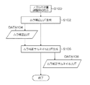
図18はインク吐出量計算前処理のフローチャートである。図18に示した処理フローは、ノズル吐出量調整開始の指示が入力されることにより開始される(ステップS100)。ノズル吐出量調整開始の指示信号は、印刷JOBの実行開始前や用紙種の交換時など、適宜のタイミングで与えられる。当該指示は、印刷制御プログラムに従って自動的に指示信号を発生してもよいし、オペレータが必要に応じて入力装置16から入力してもよい。
FIG. 18 is a flowchart of the pre-ink discharge amount calculation process. The processing flow shown in FIG. 18 is started when a nozzle discharge amount adjustment start instruction is input (step S100). The instruction signal for starting the adjustment of the nozzle discharge amount is given at an appropriate timing, such as before the start of execution of printing JOB or when the paper type is changed. The instruction may automatically generate an instruction signal according to the print control program, or may be input from the
図18の処理フローがスタートすると、まず、ムラ補正LUTを生成する処理を行う(ステップS102)。このムラ補正LUTの生成処理の一例については、図14〜図17で説明したとおりである。濃度測定用のテストパターンの印字結果を読み取って、濃度情報を取得し、ノズル毎の出力濃度特性のデータを取得し、そのデータに基づいてノズル毎の補正値を計算することによってムラ補正LUTが得られる。 When the processing flow of FIG. 18 starts, first, processing for generating a non-uniformity correction LUT is performed (step S102). An example of the unevenness correction LUT generation process is as described with reference to FIGS. The unevenness correction LUT is obtained by reading the print result of the test pattern for density measurement, obtaining density information, obtaining output density characteristic data for each nozzle, and calculating a correction value for each nozzle based on the data. can get.
図18のステップS102の処理工程で生成された全ノズル分のムラ補正LUTのデータDATA104は、PC12内のムラ補正LUTDB42に格納されるとともに、プリンタ18のイメージプロセスボード60におけるムラ補正処理部64にセットされる(図1参照)。また、このムラ補正LUTのデータ(DATA104)を基に、ムラ補正サムネイルLUTの生成処理が行われ(図18のステップS106)、ムラ補正サムネイルLUT(DATA108)が得られる。
18 is stored in the
なお、本実施形態で説明したPC12による処理内容を実現するためのプログラムをCD−ROMや磁気ディスクその他の情報記憶媒体(外部記憶装置)に記録し、該情報記憶媒体を通じて当該プログラムを第三者に提供したり、インターネットなどの通信回線を通じて当該プログラムのダウンロードサービスを提供したり、ASP(Application Service Provider)サービスとして提供したりすることも可能である。
A program for realizing the processing contents by the
また、本実施形態で説明したPC12による処理内容を実現するためのプログラム一部または全部をホストコンピュータなどの上位制御装置に組み込む態様や、プリンタ12側の中央演算処理装置(CPU)の動作プログラムとして適用することも可能である。
In addition, a mode in which a part or all of the program for realizing the processing contents by the
<インクジェット記録装置の構成例>
次に、図1で説明したプリンタ18の一例であるインクジェット記録装置の構成例について説明する。
<Configuration example of inkjet recording apparatus>
Next, a configuration example of an ink jet recording apparatus that is an example of the printer 18 described in FIG. 1 will be described.
図19は、本発明の実施形態に係るインクジェット記録装置の構成例を示す図である。このインクジェット記録装置100は、描画ドラム170に保持された記録媒体124(以下、「用紙」と呼ぶ場合がある。)にインクジェットヘッド172M,172K,172C,172Yから複数色のインクを打滴して所望のカラー画像を形成する直描方式のインクジェット記録装置であり、インクの打滴前に記録媒体124上に処理液(ここでは凝集処理液)を付与し、処理液とインク液を反応させて記録媒体124上に画像形成を行う2液反応(凝集)方式が適用されたドロップオンデマンドタイプの画像形成装置である。
FIG. 19 is a diagram illustrating a configuration example of the ink jet recording apparatus according to the embodiment of the present invention. The ink
図示のように、インクジェット記録装置100は、主として、給紙部112、処理液付与部114、描画部116、乾燥部118、定着部120、及び排紙部122を備えて構成される。
As shown in the figure, the ink
(給紙部)
給紙部112には、枚葉紙である記録媒体124が積層されている。給紙部112の給紙トレイ150から記録媒体124が一枚ずつ処理液付与部114に給紙される。記録媒体124として、枚葉紙(カット紙)を用いているが、連続用紙(ロール紙)から必要なサイズに切断して給紙する構成も可能である。
(Paper Feeder)
A
(処理液付与部)
処理液付与部114は、記録媒体124の記録面に処理液を付与する機構である。処理液は、描画部116で付与されるインク中の色材(本例では顔料)を凝集させる色材凝集剤を含んでおり、この処理液とインクとが接触することによって、インクは色材と溶媒との分離が促進される。
(Processing liquid application part)
The processing
処理液付与部114は、給紙胴152、処理液ドラム154、及び処理液塗布装置156を備えている。処理液ドラム154は、その外周面に爪形状の保持手段(グリッパー)155を備え、この保持手段155の爪と処理液ドラム154の周面の間に記録媒体124を挟み込むことによって記録媒体124の先端を保持できるようになっている。処理液ドラム154の外周面に吸引孔を設け、吸引孔から吸引を行う吸引手段を接続してもよい。これにより記録媒体124を処理液ドラム154の周面に密着保持することができる。
The processing
処理液ドラム154の周面に対向して処理液塗布装置156が配置される。処理液塗布装置156は、処理液が貯留された処理液容器と、この処理液容器の処理液に一部が浸漬されたアニックスローラと、アニックスローラと処理液ドラム154上の記録媒体124に圧接されて計量後の処理液を記録媒体124に転移するゴムローラとで構成される。この処理液塗布装置156によれば、処理液を計量しながら記録媒体124に塗布することができる。本実施形態では、ローラによる塗布方式を適用した構成を例示したが、これに限定されず、例えば、スプレー方式、インクジェット方式などの各種方式を適用することも可能である。
A treatment
処理液が付与された記録媒体124は、処理液ドラム154から中間搬送部126を介して描画部116の描画ドラム170へ受け渡される。
The
(描画部)
描画部116は、描画ドラム170、用紙抑えローラ174、及びインクジェットヘッド172M,172K,172C,172Yを備えている。描画ドラム170は、処理液ドラム154と同様に、その外周面に爪形状の保持手段(グリッパー)171を備える。
(Drawing part)
The
インクジェットヘッド172M,172K,172C,172Yはそれぞれ、記録媒体124における画像形成領域の最大幅に対応する長さを有するフルライン型のインクジェット方式の記録ヘッド(インクジェットヘッド)であり、そのインク吐出面には、画像形成領域の全幅にわたってインク吐出用のノズルが複数配列されたノズル列が形成されている。各インクジェットヘッド172M,172K,172C,172Yは、記録媒体124の搬送方向(描画ドラム170の回転方向)と直交する方向に延在するように設置される。
The inkjet heads 172M, 172K, 172C, and 172Y are full-line inkjet recording heads (inkjet heads) each having a length corresponding to the maximum width of the image forming area on the
描画ドラム170上に密着保持された記録媒体124の記録面に向かって各インクジェットヘッド172M,172K,172C,172Yから、対応する色インクの液滴が吐出されることにより、処理液付与部114で予め記録面に付与された処理液にインクが接触し、インク中に分散する色材(顔料)が凝集され、色材凝集体が形成される。これにより、記録媒体124上での色材流れなどが防止され、記録媒体124の記録面に画像が形成される。
The droplets of the corresponding color ink are ejected from the inkjet heads 172M, 172K, 172C, and 172Y toward the recording surface of the
すなわち、描画ドラム170によって記録媒体124を一定の速度で搬送し、この搬送方向について、記録媒体124と各インクジェットヘッド172M,172K,172C,172Yを相対的に移動させる動作を1回行うだけで(即ち1回の副走査で)、記録媒体124の画像形成領域に画像を記録することができる。
That is, the
描画部116で画像が形成された記録媒体124は、描画ドラム170から中間搬送部128を介して乾燥部118の乾燥ドラム176へ受け渡される。
The
(乾燥部)
乾燥部118は、色材凝集作用により分離された溶媒に含まれる水分を乾燥させる機構であり、乾燥ドラム176、及び溶媒乾燥装置178を備えている。乾燥ドラム176は、処理液ドラム154と同様に、その外周面に爪形状の保持手段(グリッパー)177を備え、この保持手段177によって記録媒体124の先端を保持できるようになっている。
(Drying part)
The drying
溶媒乾燥装置178は、乾燥ドラム176の外周面に対向する位置に配置され、複数のハロゲンヒータ180と、各ハロゲンヒータ180の間にそれぞれ配置された温風噴出しノズル182とで構成される。乾燥部118で乾燥処理が行われた記録媒体124は、乾燥ドラム176から中間搬送部130を介して定着部120の定着ドラム184へ受け渡される。
The
(定着部)
定着部120は、定着ドラム184、ハロゲンヒータ186、定着ローラ188、及びインラインセンサ190(「読取装置」に相当)で構成される。定着ドラム184は、処理液ドラム154と同様に、その外周面に爪形状の保持手段(グリッパー)185を備え、この保持手段185によって記録媒体124の先端を保持できるようになっている。
(Fixing part)
The fixing
定着ドラム184の回転により、記録媒体124の記録面に対して、ハロゲンヒータ186による予備加熱と、定着ローラ188による定着処理と、インラインセンサ190による検査が行われる。
As the fixing
定着ローラ188は、乾燥させたインクを加熱加圧することによってインク中の自己分散性ポリマー微粒子を溶着し、インクを被膜化させるためのローラ部材であり、記録媒体124を加熱加圧するように構成される。具体的には、定着ローラ188は、定着ドラム184に対して圧接するように配置されており、定着ドラム184との間でニップローラを構成するようになっている。記録媒体124は、定着ローラ188と定着ドラム184との間に挟まれ、所定のニップ圧でニップされ、定着処理が行われる。
The fixing
また、定着ローラ188は、ハロゲンランプなどを組み込んだ加熱ローラによって構成され、所定の温度に制御される。
The fixing
インラインセンサ190は、記録媒体124に形成された画像(濃度測定用のテストチャートや不吐出検出用のテストパターンなどを含む)を読み取り、画像の濃度、画像の欠陥などを検出するための手段であり、CCDラインセンサなどが適用される。
The in-
定着部120によれば、乾燥部118で形成された薄層の画像層内のラテックス粒子が定着ローラ188によって加熱加圧されて溶融されるので、記録媒体124に固定定着させることができる。また、定着ドラム184の表面温度は50℃以上に設定されている。定着ドラム184の外周面に保持された記録媒体124を裏面から加熱することによって乾燥が促進され、定着時における画像破壊を防止することができるとともに、画像温度の昇温効果によって画像強度を高めることができる。
According to the fixing
なお、高沸点溶媒及びポリマー微粒子(熱可塑性樹脂粒子)を含んだインクに代えて、UV露光にて重合硬化可能なモノマー成分を含有していてもよい。この場合、インクジェット記録装置100は、ヒートローラによる熱圧定着部(定着ローラ188)の代わりに、記録媒体124上のインクにUV光を露光するUV露光部を備える。このように、UV硬化性樹脂などの活性光線硬化性樹脂を含んだインクを用いる場合には、加熱定着の定着ローラ188に代えて、UVランプや紫外線LD(レーザダイオード)アレイなど、活性光線を照射する手段が設けられる。
In addition, instead of the ink containing the high boiling point solvent and the polymer fine particles (thermoplastic resin particles), a monomer component that can be polymerized and cured by UV exposure may be contained. In this case, the
(排紙部)
定着部120に続いて排紙部122が設けられている。排紙部122は、排出トレイ192を備えており、この排出トレイ192と定着部120の定着ドラム184との間に、これらに対接するように渡し胴194、搬送ベルト196、張架ローラ198が設けられている。記録媒体124は、渡し胴194により搬送ベルト196に送られ、排出トレイ192に排出される。搬送ベルト196による用紙搬送機構の詳細は図示しないが、印刷後の記録媒体124は無端状の搬送ベルト196間に渡されたバー(不図示)のグリッパーによって用紙先端部が保持され、搬送ベルト196の回転によって排出トレイ192の上方に運ばれてくる。
(Output section)
Subsequent to the fixing
また、図19には示されていないが、本例のインクジェット記録装置100には、上記構成の他、各インクジェットヘッド172M,172K,172C,172Yにインクを供給するインク貯蔵/装填部、処理液付与部114に対して処理液を供給する手段を備えるとともに、各インクジェットヘッド172M,172K,172C,172Yのクリーニング(ノズル面のワイピング、パージ、ノズル吸引等)を行うヘッドメンテナンス部や、用紙搬送路上における記録媒体124の位置を検出する位置検出センサ、装置各部の温度を検出する温度センサなどを備えている。
Although not shown in FIG. 19, the ink
<ヘッドの構造>
次に、ヘッドの構造について説明する。各ヘッド172M、172K、172C、172Yの構造は共通しているので、以下、これらを代表して符号250によってヘッドを示すものとする。
<Head structure>
Next, the structure of the head will be described. Since the structures of the
図20(a) はヘッド250の構造例を示す平面透視図であり、図20(b) はその一部の拡大図である。また、図21はヘッド250の他の構造例を示す平面透視図、図22は記録素子単位となる1チャンネル分の液滴吐出素子(1つのノズル251に対応したインク室ユニット)の立体的構成を示す断面図(図20中のA−A線に沿う断面図)である。
20A is a plan perspective view showing an example of the structure of the
図20(a)に示したように、本例のヘッド250は、インク吐出口であるノズル251と、各ノズル251に対応する圧力室252等からなる複数のインク室ユニット(液滴吐出素子)253をマトリクス状に二次元配置させた構造を有し、これにより、ヘッド長手方向(紙送り方向と直交する方向)に沿って並ぶように投影(正射影)される実質的なノズル間隔(投影ノズルピッチ)の高密度化を達成している。
As shown in FIG. 20A, the
記録媒体124の送り方向(矢印S方向;副走査方向)と略直交する方向(矢印M方向;主走査方向)に記録媒体124の描画領域の全幅Wmに対応する長さ以上のノズル列を構成する形態は本例に限定されない。例えば、図20(a) の構成に代えて、図21(a)に示すように、複数のノズル251が二次元に配列された短尺のヘッドモジュール250’を千鳥状に配列して繋ぎ合わせることで記録媒体124の全幅に対応する長さのノズル列を有するラインヘッドを構成する態様や、図21(b)に示すように、ヘッドモジュール250”を一列に並べて繋ぎ合わせる態様もある。
Nozzle rows having a length corresponding to the entire width Wm of the drawing area of the
各ノズル251に対応して設けられている圧力室252は、その平面形状が概略正方形となっており(図20(a)、(b) 参照)、対角線上の両隅部の一方にノズル251への流出口が設けられ、他方に供給インクの流入口(供給口)254が設けられている。なお、圧力室252の形状は、本例に限定されず、平面形状が四角形(菱形、長方形など)、五角形、六角形その他の多角形、円形、楕円形など、多様な形態があり得る。
The
図22に示すように、ヘッド250は、ノズル251が形成されたノズルプレート251Aと、圧力室252や共通流路255等の流路が形成された流路板252P等を積層接合した構造から成る。
As shown in FIG. 22, the
流路板252Pは、圧力室252の側壁部を構成するとともに、共通流路255から圧力室252にインクを導く個別供給路の絞り部(最狭窄部)としての供給口254を形成する流路形成部材である。なお、説明の便宜上、図22では簡略的に図示しているが、流路板252Pは一枚又は複数の基板を積層した構造である。
The
ノズルプレート251A及び流路板252Pは、シリコンを材料として半導体製造プロセスによって所要の形状に加工することが可能である。
The
共通流路255はインク供給源たるインクタンク(不図示)と連通しており、インクタンクから供給されるインクは共通流路255を介して各圧力室252に供給される。
The
圧力室252の一部の面(図22において天面)を構成する振動板256には、個別電極257を備えた圧電アクチュエータ258が接合されている。本例の振動板256は、圧電アクチュエータ258の下部電極に相当する共通電極259として機能するニッケル(Ni)導電層付きのシリコン(Si)から成り、各圧力室252に対応して配置される圧電アクチュエータ258の共通電極を兼ねる。なお、樹脂などの非導電性材料によって振動板を形成する態様も可能であり、この場合は、振動板部材の表面に金属などの導電材料による共通電極層が形成される。また、ステンレス鋼(SUS)など、金属(導電性材料)によって共通電極を兼ねる振動板を構成してもよい。
A
個別電極257に駆動電圧を印加することによって圧電アクチュエータ258が変形して圧力室252の容積が変化し、これに伴う圧力変化によりノズル251からインクが吐出される。インク吐出後、圧電アクチュエータ258が元の状態に戻る際、共通流路255から供給口254を通って新しいインクが圧力室252に再充填される。
By applying a driving voltage to the
かかる構造を有するインク室ユニット253を図20(b)に示す如く、主走査方向に沿う行方向及び主走査方向に対して直交しない一定の角度θを有する斜めの列方向に沿って一定の配列パターンで格子状に多数配列させることにより、本例の高密度ノズルヘッドが実現されている。かかるマトリクス配列において、副走査方向の隣接ノズル間隔をLsとするとき、主走査方向については実質的に各ノズル251が一定のピッチP=Ls/tanθで直線状に配列されたものと等価的に取り扱うことができる。
As shown in FIG. 20B, the
ノズル251の配列形態は図示の例に限定されず、様々なノズル配置構造を適用できる。例えば、一列の直線配列、V字状のノズル配列、V字状配列を繰り返し単位とするジグザク状(W字状など)のような折れ線状のノズル配列なども可能である。
The arrangement form of the
<実施形態の用語と請求項の用語の対応関係>
PC12とモニタ14及び入力装置16の組み合わせが「インク使用量評価装置」に相当する。画像入力インターフェース部22が「画像入力手段」に相当し、画像データDB24が「画像データ格納手段」に相当する。階調変換LUTが「第1LUT」に相当し、階調変換LUTDB40が「第1LUT格納手段」に相当する。ムラ補正LUTが「第2LUT」に相当し、ムラ補正LUTDB42が「第2LUT格納手段」に相当する。ムラ補正サムネイルLUTが「第3LUT」に相当し、ムラ補正サムネイルLUT生成部56が「第3LUT生成手段」に相当する。画像縮小処理部32、画像変換部34、インク量データ算出部36、画像解析部38がそれぞれ「画像縮小処理手段」、「画像変換手段」、「インク量分布データ算出手段」、「画像解析手段」に相当する。濃度測定用のテストチャートの読取データから濃度情報を得る構成が「濃度情報取得手段」に相当する。LUT生成部54が「第2LUT生成手段」に相当する。インクジェット印刷システム10が「インクジェット装置」に相当する。イメージプロセスボード60が「画像処理手段」に相当し、システム制御部50とイメージプロセスボード60の組み合わせが「吐出制御手段」に相当する。
<Correspondence Relationship between Terms in Embodiment and Terms in Claims>
A combination of the
<変形例>
上記実施形態では、記録媒体124に直接インク滴を打滴して画像を形成する方式(直接記録方式)のインクジェット記録装置を説明したが、本発明の適用範囲はこれに限定されず、一旦、中間転写体上に画像(一次画像)を形成し、その画像を転写部において記録紙に対して転写することで最終的な画像形成を行う中間転写型の画像形成装置についても本発明を適用することができる。
<Modification>
In the above embodiment, an ink jet recording apparatus of a method (direct recording method) in which an ink droplet is directly formed on the
<ヘッドと用紙を相対移動させる手段について>
上述の実施形態では、停止したヘッドに対して記録媒体を搬送する構成を例示したが、本発明の実施に際しては、停止した記録媒体(被描画媒体)に対してヘッドを移動させる構成も可能である。
<Means for moving the head and paper relative to each other>
In the above-described embodiment, the configuration in which the recording medium is transported to the stopped head is exemplified. However, in the implementation of the present invention, a configuration in which the head is moved with respect to the stopped recording medium (the drawing medium) is also possible. is there.
<記録媒体について>
「記録媒体」は、インクジェットヘッドから吐出された液滴によってドットが記録される媒体の総称であり、印字媒体、被記録媒体、被画像形成媒体、受像媒体、被吐出媒体など様々な用語で呼ばれるものが含まれる。本発明の実施に際して、記録媒体の材質や形状等は、特に限定されず、連続用紙、カット紙、シール用紙、OHPシート等の樹脂シート、フィルム、布、不織布、配線パターン等が形成されるプリント基板、ゴムシート、その他材質や形状を問わず、様々な媒体に適用できる。
<About recording media>
“Recording medium” is a general term for media on which dots are recorded by droplets ejected from an inkjet head, and is called by various terms such as a printing medium, a recording medium, an image forming medium, an image receiving medium, and a discharging medium. Things are included. In the practice of the present invention, the material, shape, etc. of the recording medium are not particularly limited, and a print on which a resin sheet such as continuous paper, cut paper, seal paper, OHP sheet, film, cloth, nonwoven fabric, wiring pattern, or the like is formed. It can be applied to various media regardless of the substrate, rubber sheet, and other materials and shapes.
上述の実施形態では、コックリングによる用紙変形の観点からインク使用量を制限する例を説明したが、インク使用量の評価に関しては記録媒体(用紙)がインクの水分を吸収して変形するか否かは必ずしも必要な条件ではない。すなわち、インク液が浸透しない非浸透性媒体(或いは浸透性の低い低浸透性媒体)を用いる場合であっても、本発明を適用してインク使用量を正確に把握することができる。 In the above-described embodiment, the example in which the ink use amount is limited from the viewpoint of paper deformation by cockling has been described. However, regarding the evaluation of the ink use amount, whether or not the recording medium (paper) deforms by absorbing ink moisture. This is not always a necessary condition. That is, even when a non-permeable medium (or a low-permeable medium with low permeability) that does not allow ink liquid to permeate is used, the amount of ink used can be accurately grasped by applying the present invention.
<吐出方式について>
なお、インクジェットヘッドにおける各ノズルから液滴を吐出させるための吐出用の圧力(吐出エネルギー)を発生させる手段は、ピエゾアクチュエータ(圧電素子)に限らない。圧電素子の他、静電アクチュエータ、サーマル方式(ヒータの加熱による膜沸騰の圧力を利用してインクを吐出させる方式)におけるヒータ(加熱素子)や他の方式による各種アクチュエータなど様々な圧力発生素子(吐出エネルギー発生素子)を適用し得る。ヘッドの吐出方式に応じて、相応のエネルギー発生素子が流路構造体に設けられる。
<Discharge method>
The means for generating discharge pressure (discharge energy) for discharging droplets from each nozzle in the inkjet head is not limited to a piezo actuator (piezoelectric element). In addition to piezoelectric elements, various pressure generating elements (such as heaters (heating elements) in electrostatic actuators, thermal methods (methods that eject ink using the pressure of film boiling by heating of the heaters), and various other actuators) A discharge energy generating element) can be applied. Corresponding energy generating elements are provided in the flow path structure according to the ejection method of the head.
<装置応用例>
上記の実施形態では、グラフィック印刷用のインクジェット記録装置への適用を例に説明したが、本発明の適用範囲はこの例に限定されない。例えば、電子回路の配線パターンを描画する配線描画装置、各種デバイスの製造装置、吐出用の機能性液体として樹脂液を用いるレジスト印刷装置、カラーフィルター製造装置、マテリアルデポジション用の材料を用いて微細構造物を形成する微細構造物形成装置など、液状機能性材料を用いて様々な形状やパターンを描画するインクジェット装置に広く適用できる。
<Device application example>
In the above embodiment, application to an inkjet recording apparatus for graphic printing has been described as an example, but the scope of application of the present invention is not limited to this example. For example, a wiring drawing apparatus for drawing a wiring pattern of an electronic circuit, a manufacturing apparatus for various devices, a resist printing apparatus that uses a resin liquid as a functional liquid for ejection, a color filter manufacturing apparatus, and a material deposition material. The present invention can be widely applied to an inkjet apparatus that draws various shapes and patterns using a liquid functional material, such as a fine structure forming apparatus that forms a structure.
「インク」という用語は、インクジェット方式の液体吐出ヘッドから吐出する液体(機能性液体)の総称として解釈することができ、グラフィック印刷に用いるカラーインク(色材を含有したインク)に限定されない。微粒子含有インクなど、機能性材料を含有した液体も「インク」という用語の解釈に含まれる。 The term “ink” can be interpreted as a general term for liquids (functional liquids) ejected from an ink jet type liquid ejection head, and is not limited to color inks (inks containing color materials) used for graphic printing. Liquids containing functional materials such as fine particle-containing ink are also included in the interpretation of the term “ink”.
なお、本発明は以上説明した実施形態に限定されるものではなく、本発明の技術的思想内で当該分野の通常の知識を有するものにより、多くの変形が可能である。 The present invention is not limited to the embodiments described above, and many modifications can be made by those having ordinary knowledge in the field within the technical idea of the present invention.
<開示する発明の各種態様>
上記に詳述した実施形態についての記載から把握されるとおり、本明細書及び図面は以下に示す発明を含む多様な技術思想の開示を含んでいる。
<Various aspects of the disclosed invention>
As will be understood from the description of the embodiment described in detail above, the present specification and drawings include disclosure of various technical ideas including the invention described below.
(第1態様):画像データを受け入れる画像入力手段と、前記画像入力手段を介して受入した画像データから当該画像データよりも解像度の低い縮小画像データを生成する画像縮小処理手段と、前記縮小画像データに対して階調変換を行うための入出力関係を規定した第1のルックアップテーブル(以下「第1LUT」という。)を格納する第1LUT格納手段と、前記画像データに応じてインクの吐出を行う複数のノズルを有する液体吐出ヘッドにおける各ノズルのインク吐出量をノズル単位で補正するための信号変換の関係を規定した第2のルックアップテーブル(以下、「第2LUT」という。)を格納する第2LUT格納手段と、前記各ノズルに対応して割り当てられている前記第2LUTから、前記縮小画像データの解像度に応じた一定幅の単位で前記縮小画像データの信号値を補正する第3のルックアップテーブル(以下、「第3LUT」という。)を生成する第3LUT生成手段と、前記画像縮小処理手段にて生成された前記縮小画像データに対して前記第1LUTと前記第3LUTを適用した変換処理を行う画像変換手段と、前記画像変換手段で得られた変換後の縮小画像データから、当該縮小画像データに対応する画像内容の描画に使用されるインク量の分布を示すインク量分布データを作成するインク量分布データ算出手段と、前記インク量分布データを解析して、規定値以上のインク量が使用されるか否かを判定する画像解析手段と、を備えるインク使用量評価装置。 (First aspect): Image input means for receiving image data, image reduction processing means for generating reduced image data having a resolution lower than that of the image data from the image data received via the image input means, and the reduced image First LUT storage means for storing a first look-up table (hereinafter referred to as “first LUT”) that defines an input / output relationship for performing gradation conversion on data, and ejection of ink according to the image data A second look-up table (hereinafter referred to as “second LUT”) that defines the relationship of signal conversion for correcting the ink discharge amount of each nozzle in a liquid discharge head having a plurality of nozzles for each nozzle is stored. According to the resolution of the reduced image data from the second LUT storage means to be assigned and the second LUT assigned to each of the nozzles. A third look-up table for generating a third look-up table (hereinafter referred to as “third LUT”) for correcting the signal value of the reduced image data in a unit of a constant width, and the image reduction processing means. An image conversion unit that performs conversion processing applying the first LUT and the third LUT to the reduced image data, and an image corresponding to the reduced image data from the reduced image data obtained by the image conversion unit. Ink amount distribution data calculating means for creating ink amount distribution data indicating the distribution of the ink amount used for drawing the content, and analyzing the ink amount distribution data, whether or not an ink amount greater than a prescribed value is used An ink usage evaluation device comprising: an image analysis means for determining whether or not.
第1態様に係るインク使用量評価装置によれば、画像調整のパラメータ条件(第1LUT、第2LUTの条件)を反映した正確なインク使用量の計算が可能であり、描画品質に影響を及ぼすか否かを精度よく判定することが可能である。 According to the ink usage amount evaluation apparatus according to the first aspect, it is possible to accurately calculate the ink usage amount reflecting the image adjustment parameter conditions (first LUT and second LUT conditions), and to affect drawing quality. It is possible to accurately determine whether or not.
(第2態様):第1態様に記載のインク使用量評価装置において、前記第3LUT生成手段は、前記各ノズルに対応して割り当てられている前記第2LUTから前記一定幅ごとに1つのルックアップテーブルに編集して前記第3LUTを生成する構成とすることができる。 (Second Aspect): In the ink usage evaluation apparatus according to the first aspect, the third LUT generating means performs one lookup for each fixed width from the second LUT assigned corresponding to each nozzle. The table can be edited to generate the third LUT.
(第3態様):第2態様に記載のインク使用量評価装置において、前記第3LUT生成手段は、前記縮小画像データの解像度における1画素当たりの幅に相当する範囲を前記1つのルックアップテーブルに編集して前記第3LUTを生成する構成とすることができる。 (Third Aspect): In the ink usage evaluation apparatus according to the second aspect, the third LUT generating means uses a range corresponding to the width per pixel in the resolution of the reduced image data in the one look-up table. The third LUT can be generated by editing.
例えば、縮小画像データの1画素当たりの幅に対応する第2LUTのデータを平均化して縮小画像の1画素に対応するLUT(第3LUT)を作ることができる。或いはまた、縮小画像の1画素当たりの幅に対応する第2LUTのデータの中から、最も大きな値を持つLUTを縮小画像の1画素に対応するLUT(第3LUT)とすることができる。 For example, the data of the second LUT corresponding to the width per pixel of the reduced image data can be averaged to create an LUT (third LUT) corresponding to one pixel of the reduced image. Alternatively, the LUT having the largest value among the data of the second LUT corresponding to the width per pixel of the reduced image can be set as the LUT (third LUT) corresponding to one pixel of the reduced image.
(第4態様):第1態様から第3態様のいずれか1項に記載のインク使用量評価装置において、前記液体吐出ヘッドにおける前記ノズル毎の記録濃度特性を示す出力濃度データを取得する濃度情報取得手段と、前記出力濃度データから前記ノズル毎の濃度補正値を算出して前記第2LUTを生成する第2LUT生成手段と、を備える構成とすることができる。 (Fourth Aspect): In the ink usage evaluation apparatus according to any one of the first aspect to the third aspect, density information for obtaining output density data indicating recording density characteristics for each nozzle in the liquid ejection head. An acquisition means and a second LUT generation means for calculating the density correction value for each nozzle from the output density data and generating the second LUT can be employed.
必要に応じて第2LUTを新たに生成することができ最新のデータに更新することができる。 If necessary, the second LUT can be newly generated and updated to the latest data.
(第5態様):第1態様から第4態様のいずれか1項に記載のインク使用量評価装置において、前記第2LUT生成手段によって前記第2LUTが生成されると、当該最新の第2LUTから前記第3LUTが生成され、当該最新の第3LUTが前記画像変換手段に適用される構成とすることができる。 (Fifth Aspect): In the ink use amount evaluation apparatus according to any one of the first aspect to the fourth aspect, when the second LUT is generated by the second LUT generation unit, the latest LUT is used to generate the second LUT. The third LUT may be generated, and the latest third LUT may be applied to the image conversion unit.
かかる態様によれば、常に最新のパラメータが反映される。 According to this aspect, the latest parameter is always reflected.
(第6態様):第1態様から第5態様のいずれか1項に記載のインク使用量評価装置において、前記第2LUTの生成に伴い、当該第2LUTの生成直後に前記第3LUTも生成される構成とすることができる。 (Sixth aspect): In the ink usage evaluation apparatus according to any one of the first aspect to the fifth aspect, the third LUT is generated immediately after the second LUT is generated as the second LUT is generated. It can be configured.
かかる態様によれば、常に最新のパラメータが反映される。また、演算処理時間の短縮を達成できる。 According to this aspect, the latest parameter is always reflected. In addition, the calculation processing time can be shortened.
(第7態様):第1態様から第6態様のいずれか1項に記載のインク使用量評価装置において、前記インク量分布データは、信号のビット深度が16ビット以上であることが好ましい。 (Seventh aspect): In the ink use amount evaluation apparatus according to any one of the first aspect to the sixth aspect, the ink amount distribution data preferably has a signal bit depth of 16 bits or more.
画像解析手段によるインク使用量の評価演算の際のインク量分解能を確保するために、インク量分布データの信号の深度は、入力された元の画像データ(画像縮小処理前の画像データ)の信号の深度よりもビット数が多いことが好ましい。 In order to ensure the ink amount resolution in the ink use amount evaluation calculation by the image analysis means, the depth of the ink amount distribution data signal is the signal of the input original image data (image data before image reduction processing). The number of bits is preferably larger than the depth of.
(第8態様):第1態様から第7態様のいずれか1項に記載のインク使用量評価装置において、前記画像解析手段は、前記インク量分布データに対して、画像内の所定面積に相当するサイズのフィルタを適用し、当該所定面積内に規定値以上のインク量が使用されるか否かを判定する構成とすることができる。 (Eighth aspect): In the ink usage evaluation apparatus according to any one of the first to seventh aspects, the image analysis unit corresponds to a predetermined area in the image with respect to the ink amount distribution data. It is possible to adopt a configuration in which a filter having a size to be applied is applied and whether or not an ink amount equal to or greater than a specified value is used within the predetermined area is determined.
フィルタの種類は1種類であってもよいし、複数種類であってもよい。フィルタの種類毎に規定値(閾値)を設定する構成も可能である。 There may be one type of filter or a plurality of types. A configuration in which a specified value (threshold value) is set for each type of filter is also possible.
(第9態様):第1態様から第8態様のいずれか1項に記載のインク使用量評価装置において、前記画像解析手段による解析の結果に応じた表示を行う表示手段を備える構成とすることができる。 (Ninth aspect): In the ink usage evaluation apparatus according to any one of the first aspect to the eighth aspect, the apparatus includes a display unit that performs display according to an analysis result by the image analysis unit. Can do.
インク使用量の評価結果(判定結果)に応じた表示制御を行うユーザーインターフェース(UI)制御手段を備え、オペレータに対し、警告等の報知を行う構成が好ましい。 A configuration that includes a user interface (UI) control unit that performs display control according to the evaluation result (determination result) of the ink usage amount, and notifies the operator of a warning or the like is preferable.
(第10態様):第9態様に記載のインク使用量評価装置において、前記画像入力手段から取り込んだ画像データを保存しておく画像データ格納手段を備え、前記表示手段には、前記画像データ格納手段に保存された登録画像の一覧に対応する表示とともに、前記画像解析手段による解析結果に基づき各登録画像のインク使用量の状況が表示される構成とすることができる。 (Tenth aspect): The ink usage evaluation apparatus according to the ninth aspect, further comprising image data storage means for storing image data captured from the image input means, wherein the display means stores the image data storage. In addition to the display corresponding to the list of registered images stored in the means, the status of ink usage of each registered image can be displayed based on the analysis result by the image analysis means.
(第11態様):第9態様に記載のインク使用量評価装置において、前記画像入力手段から取り込んだ画像データを保存しておく画像データ格納手段を備え、前記画像データ格納手段に保存された登録画像の一覧を前記表示手段に表示させる際に、前記画像解析手段による解析結果に基づき各登録画像のインク使用量の状況に応じてジョブが分類され、当該分類されたジョブ群のまとまりで前記表示手段に表示される構成とすることができる。 (Eleventh aspect): The ink usage evaluation apparatus according to the ninth aspect, further comprising image data storage means for storing the image data fetched from the image input means, and the registration saved in the image data storage means When displaying a list of images on the display means, jobs are classified according to the status of ink usage of each registered image based on the analysis result by the image analysis means, and the display is performed according to a group of the classified job groups. It can be configured to be displayed on the means.
第10態様や第11態様のようなユーザーインターフェース表示制御を行う構成に加えて、インク使用量が規定値を超えないようにインク量と調整するための調整手段を備える構成が好ましい。調整手段として、例えば、第1LUTを変更するなどの態様がある。 In addition to the configuration for performing user interface display control as in the tenth aspect and the eleventh aspect, a configuration including an adjusting unit for adjusting the ink amount so that the ink usage amount does not exceed a specified value is preferable. As an adjusting means, for example, there is an aspect such as changing the first LUT.
(第12態様):第10態様又は第11態様に記載のインク使用量評価装置において、前記第1LUT及び前記第2LUTのうち少なくとも一方が更新されたら、当該更新されたLUTを反映させて、前記登録画像についてのインク使用量を再計算し、当該再計算した結果に応じて前記表示手段の表示を更新する構成とすることが好ましい。 (Twelfth aspect): In the ink usage evaluation apparatus according to the tenth aspect or the eleventh aspect, when at least one of the first LUT and the second LUT is updated, the updated LUT is reflected, and It is preferable that the amount of ink used for the registered image is recalculated and the display of the display unit is updated according to the recalculated result.
(第13態様):第1態様から第12態様のいずれか1項に記載のインク使用量評価装置において、前記インク量分布データ算出手段は、前記縮小画像データの信号値と当該信号値に対応するハーフトーン処理によって得られるドット配置におけるドットサイズ別比率の関係を規定したハーフトーンテーブルと、各ドットサイズのインク滴量の情報に基づいて、前記縮小画像データの1画素あたりのインク量を求める構成を含むものとすることができる。 (Thirteenth aspect): In the ink use amount evaluation apparatus according to any one of the first aspect to the twelfth aspect, the ink amount distribution data calculation unit corresponds to the signal value of the reduced image data and the signal value. The amount of ink per pixel of the reduced image data is obtained based on a halftone table that defines the relationship between the dot size ratios in the dot arrangement obtained by the halftone processing and the ink droplet amount information of each dot size. Configurations can be included.
(第14態様):第1態様から第13態様のいずれか1項に記載のインク使用量評価装置において、前記画像縮小処理手段は、入力された元の前記画像データから、前記縮小画像データの1画素あたりのサイズに相当する範囲の座標に対応する前記元の画像データの画素を平均化することにより、前記縮小画像データの1画素当たりの信号値を決めて前記縮小画像データを生成する構成とすることができる。 (Fourteenth aspect): In the ink usage evaluation apparatus according to any one of the first to thirteenth aspects, the image reduction processing means is configured to calculate the reduced image data from the input original image data. A configuration for generating the reduced image data by determining the signal value per pixel of the reduced image data by averaging the pixels of the original image data corresponding to the coordinates in a range corresponding to the size per pixel. It can be.
(第15態様):第1態様から第13態様のいずれか1項に記載のインク使用量評価装置において、前記画像縮小処理手段は、入力された元の前記画像データから、前記縮小画像データの1画素あたりのサイズに相当する範囲の座標に対応する前記元の画像データの画素を加算し、その加算値を前記縮小画像データのビット深度のいずれかの値に割り当てる処理を行い、前記縮小画像データを生成する構成とすることができる。 (Fifteenth aspect): In the ink usage evaluation apparatus according to any one of the first aspect to the thirteenth aspect, the image reduction processing means is configured to calculate the reduced image data from the input original image data. A process of adding pixels of the original image data corresponding to coordinates in a range corresponding to a size per pixel, and assigning the added value to any value of the bit depth of the reduced image data; It can be set as the structure which produces | generates data.
(第16態様):第1態様から第15態様のいずれか1項に記載のインク使用量評価装置において、前記縮小画像データは、信号のビット深度が16ビット以上とすることが好ましい。 (Sixteenth aspect): In the ink usage evaluation apparatus according to any one of the first to fifteenth aspects, the reduced image data preferably has a signal bit depth of 16 bits or more.
画像解析手段によるインク使用量の評価演算の際のインク量分解能を確保するために、インク量分布データの信号の深度は、入力された元の画像データ(画像縮小処理前の画像データ)の信号の深度よりもビット数が多いことが好ましい。 In order to ensure the ink amount resolution in the ink use amount evaluation calculation by the image analysis means, the depth of the ink amount distribution data signal is the signal of the input original image data (image data before image reduction processing). The number of bits is preferably larger than the depth of.
(第17態様):画像データを取り込む画像入力工程と、前記画像入力工程で取り込んだ画像データから当該画像データよりも解像度の低い縮小画像データを生成する画像縮小処理工程と、前記縮小画像データに対して階調変換を行うための入出力関係を規定した第1のルックアップテーブル(以下「第1LUT」という。)を格納しておく第1LUT格納工程と、前記画像データに応じてインクの吐出を行う複数のノズルを有する液体吐出ヘッドにおける各ノズルのインク吐出量をノズル単位で補正するための信号変換の関係を規定した第2のルックアップテーブル(以下、「第2LUT」という。)を格納しておく第2LUT格納工程と、前記各ノズルに対応して割り当てられている前記第2LUTから、前記縮小画像データの解像度に対応した一定幅の単位で前記縮小画像データの信号値を補正する第3のルックアップテーブル(以下、「第3LUT」という。)を生成する第3LUT生成工程と、前記画像縮小処理工程にて生成された前記縮小画像データに対して前記第1LUTと前記第3LUTを適用した変換処理を行う画像変換工程と、前記画像変換工程で得られた変換後の縮小画像データから、当該縮小画像データに対応する画像内容の描画に使用されるインク量の分布を示すインク量分布データを作成するインク量分布データ算出工程と、前記インク量分布データを解析して、規定値以上のインク量が使用されるか否かを判定する画像解析工程と、を含むインク使用量評価方法。 (Seventeenth aspect): An image input step for capturing image data, an image reduction processing step for generating reduced image data having a resolution lower than that of the image data from the image data acquired in the image input step, and the reduced image data A first LUT storing step for storing a first look-up table (hereinafter referred to as a “first LUT”) that defines an input / output relationship for performing gradation conversion on the ink, and ejection of ink according to the image data A second look-up table (hereinafter referred to as “second LUT”) that defines the relationship of signal conversion for correcting the ink discharge amount of each nozzle in a liquid discharge head having a plurality of nozzles for each nozzle is stored. The second LUT storing step to be performed and the second LUT assigned to each nozzle are used to obtain the resolution of the reduced image data. A third LUT generation step for generating a third look-up table (hereinafter referred to as “third LUT”) that corrects the signal value of the reduced image data in units of a constant width, and the image reduction processing step. Corresponding to the reduced image data from the image conversion step for performing the conversion process applying the first LUT and the third LUT to the reduced image data, and the reduced image data after the conversion obtained in the image conversion step An ink amount distribution data calculation step for creating ink amount distribution data indicating the distribution of the ink amount used for rendering the image content to be analyzed, and the ink amount distribution data is analyzed, and an ink amount equal to or greater than a specified value is used. And an image analysis step for determining whether or not the ink is used.
第17態様に記載の方法発明において、第2態様から第16態様に記載の特徴と同様の組み合わせる構成が可能である。 In the method invention described in the seventeenth aspect, the same combination as the characteristics described in the second to sixteenth aspects is possible.
(第18態様):コンピュータに、画像データを取り込む画像入力機能と、前記画像入力機能を介して受入した画像データから当該画像データよりも解像度の低い縮小画像データを生成する画像縮小処理機能と、前記縮小画像データに対して階調変換を行うための入出力関係を規定した第1のルックアップテーブル(以下「第1LUT」という。)を格納する第1LUT格納機能と、前記画像データに応じてインクの吐出を行う複数のノズルを有する液体吐出ヘッドにおける各ノズルの液体吐出量をノズル単位で補正するための信号変換の関係を規定した第2のルックアップテーブル(以下、「第2LUT」という。)を格納する第2LUT格納機能と、前記各ノズルに対応して割り当てられている前記第2LUTから、前記縮小画像データの解像度に対応した一定幅の単位で前記縮小画像データの信号値を補正する第3のルックアップテーブル(以下、「第3LUT」という。)を生成する第3LUT生成機能と、前記画像縮小処理機能にて生成された前記縮小画像データに対して前記第1LUTと前記第3LUTを適用した変換処理を行う画像変換機能と、前記画像変換機能で得られた変換後の縮小画像データから、当該縮小画像データに対応する画像内容の描画に使用されるインク量の分布を示すインク量分布データを作成するインク量分布データ算出機能と、前記インク量分布データを解析して、規定値以上のインク量が使用されるか否かを判定する画像解析機能と、を実現させるためのプログラム。 (Eighteenth aspect): An image input function for capturing image data into a computer, an image reduction processing function for generating reduced image data having a lower resolution than the image data from image data received via the image input function, A first LUT storage function for storing a first look-up table (hereinafter referred to as “first LUT”) that defines an input / output relationship for performing gradation conversion on the reduced image data, and in accordance with the image data A second look-up table (hereinafter referred to as “second LUT”) that defines the relationship of signal conversion for correcting the liquid ejection amount of each nozzle in a liquid ejection head having a plurality of nozzles that eject ink. ) From the second LUT storage function and the second LUT assigned corresponding to each nozzle, the reduced image data A third LUT generation function for generating a third look-up table (hereinafter referred to as “third LUT”) for correcting the signal value of the reduced image data in a unit of a constant width corresponding to the resolution, and the image reduction processing function. An image conversion function for performing conversion processing applying the first LUT and the third LUT to the reduced image data generated in the above, and the reduced image data from the reduced image data after conversion obtained by the image conversion function. Ink amount distribution data calculation function for creating ink amount distribution data indicating the distribution of the ink amount used for drawing the image content corresponding to the A program for realizing an image analysis function for determining whether or not to be performed.
第18態様に記載のプログラムの発明において、第2態様から第16態様に記載の特徴と同様の組み合わせる構成が可能である。 In the program invention described in the eighteenth aspect, the same combination as the characteristics described in the second aspect to the sixteenth aspect is possible.
(第19態様):複数のノズルを有する液体吐出ヘッドと、前記液体吐出ヘッドに対して記録媒体を相対移動させる媒体搬送手段と、入力される画像データに対して、前記第1LUT、前記第2LUT、及び信号値に対応して単位面積あたりのドットサイズ別比率が定められたハーフトーンテーブルに基づく信号処理を行い、2値又は多値のデータを生成する画像処理手段と、前記画像処理手段で生成されたデータに基づいて前記液体吐出ヘッドの各ノズルの吐出を制御する吐出制御手段と、第1態様から第16態様のいずれか1項に記載のインク使用量評価装置と、を備えたことを特徴とするインクジェット装置。 (Nineteenth aspect): a liquid discharge head having a plurality of nozzles, a medium transport unit that moves a recording medium relative to the liquid discharge head, and the first LUT and the second LUT for input image data And image processing means for generating binary or multivalued data by performing signal processing based on a halftone table in which a ratio by dot size per unit area is determined corresponding to the signal value , and the image processing means An ejection control unit that controls ejection of each nozzle of the liquid ejection head based on the generated data, and the ink usage amount evaluation device according to any one of the first aspect to the sixteenth aspect are provided. An inkjet apparatus characterized by the above.
(第20態様):第19態様に記載のインクジェット装置において、前記液体吐出ヘッドは、前記記録媒体に対する1回の相対移動で画像を記録するシングルパス方式のヘッドとする構成が好ましい。 (20th aspect): In the ink jet apparatus according to the 19th aspect, it is preferable that the liquid discharge head is a single-pass type head that records an image by one relative movement with respect to the recording medium.
10…インクジェット印刷システム、12…コンピュータ本体(PC)、14…モニタ、16…入力装置、18…プリンタ、20…画像データ、22…画像入力インターフェース部、24…画像データDB、30…画像データ処理部、32…画像縮小処理部、34…画像変換部、36…インク量データ算出部、38…画像解析部、40…階調変換LUTDB、42…ムラ補正LUTDB、44…ハーフトーンDB、50…システム制御部、52…UI制御部、54…LUT生成部、56…ムラ補正サムネイルLUT生成部、60…イメージプロセスボード、62…階調変換処理部、64…ムラ補正処理部、66…ハーフトーン処理部、68…マーキング部、90…テストチャート、92…記録媒体、100…インクジェット記録装置、124…記録媒体、170…描画ドラム、172M,172K,172C,172Y…インクジェットヘッド、251…ノズル
DESCRIPTION OF
Claims (20)
前記画像入力手段を介して受入した画像データから当該画像データよりも解像度の低い縮小画像データを生成する画像縮小処理手段と、
前記縮小画像データに対して階調変換を行うための入出力関係を規定した第1のルックアップテーブル(以下「第1LUT」という。)を格納する第1LUT格納手段と、
前記画像データに応じてインクの吐出を行う複数のノズルを有する液体吐出ヘッドにおける各ノズルのインク吐出量をノズル単位で補正するための信号変換の関係を規定した第2のルックアップテーブル(以下、「第2LUT」という。)を格納する第2LUT格納手段と、
前記各ノズルに対応して割り当てられている前記第2LUTから、前記縮小画像データの解像度に応じた一定幅の単位で前記縮小画像データの信号値を補正する第3のルックアップテーブル(以下、「第3LUT」という。)を生成する第3LUT生成手段と、
前記画像縮小処理手段にて生成された前記縮小画像データに対して前記第1LUTと前記第3LUTを適用した変換処理を行う画像変換手段と、
前記画像変換手段で得られた変換後の縮小画像データから、当該縮小画像データに対応する画像内容の描画に使用されるインク量の分布を示すインク量分布データを作成するインク量分布データ算出手段と、
前記インク量分布データを解析して、規定値以上のインク量が使用されるか否かを判定する画像解析手段と、
を備えるインク使用量評価装置。 Image input means for receiving image data;
Image reduction processing means for generating reduced image data having a lower resolution than the image data from the image data received via the image input means;
First LUT storage means for storing a first look-up table (hereinafter referred to as “first LUT”) defining an input / output relationship for performing gradation conversion on the reduced image data;
A second look-up table (hereinafter, referred to as a signal conversion relationship for correcting the ink discharge amount of each nozzle in a liquid discharge head having a plurality of nozzles that discharge ink in accordance with the image data in units of nozzles. Second LUT storage means for storing “second LUT”);
From the second LUT assigned corresponding to each nozzle, a third look-up table (hereinafter, “ A third LUT generating means for generating a third LUT ”),
Image conversion means for performing conversion processing applying the first LUT and the third LUT to the reduced image data generated by the image reduction processing means;
Ink amount distribution data calculation means for creating ink amount distribution data indicating the distribution of the ink amount used for rendering the image content corresponding to the reduced image data from the reduced image data after conversion obtained by the image conversion means When,
Image analysis means for analyzing the ink amount distribution data and determining whether or not an ink amount greater than a specified value is used;
An ink usage evaluation apparatus comprising:
前記出力濃度データから前記ノズル毎の濃度補正値を算出して前記第2LUTを生成する第2LUT生成手段と、
を備える請求項1から3のいずれか1項に記載のインク使用量評価装置。 Density information acquisition means for acquiring output density data indicating recording density characteristics for each of the nozzles in the liquid ejection head;
Second LUT generation means for calculating a density correction value for each nozzle from the output density data and generating the second LUT;
An ink use amount evaluation apparatus according to any one of claims 1 to 3.
前記表示手段には、前記画像データ格納手段に保存された登録画像の一覧に対応する表示とともに、前記画像解析手段による解析結果に基づき各登録画像のインク使用量の状況が表示される請求項9に記載のインク使用量評価装置。 Image data storage means for storing image data captured from the image input means;
10. The display unit displays a status corresponding to a list of registered images stored in the image data storage unit and a status of ink usage of each registered image based on an analysis result by the image analysis unit. The ink usage evaluation apparatus according to 1.
前記画像データ格納手段に保存された登録画像の一覧を前記表示手段に表示させる際に、前記画像解析手段による解析結果に基づき各登録画像のインク使用量の状況に応じてジョブが分類され、当該分類されたジョブ群のまとまりで前記表示手段に表示される請求項9に記載のインク使用量評価装置。 Image data storage means for storing image data captured from the image input means;
When displaying a list of registered images stored in the image data storage unit on the display unit, jobs are classified according to the status of ink usage of each registered image based on the analysis result by the image analysis unit, The ink usage evaluation apparatus according to claim 9, wherein the display unit displays a group of classified job groups.
前記画像入力工程で取り込んだ画像データから当該画像データよりも解像度の低い縮小画像データを生成する画像縮小処理工程と、
前記縮小画像データに対して階調変換を行うための入出力関係を規定した第1のルックアップテーブル(以下「第1LUT」という。)を格納しておく第1LUT格納工程と、
前記画像データに応じてインクの吐出を行う複数のノズルを有する液体吐出ヘッドにおける各ノズルのインク吐出量をノズル単位で補正するための信号変換の関係を規定した第2のルックアップテーブル(以下、「第2LUT」という。)を格納しておく第2LUT格納工程と、
前記各ノズルに対応して割り当てられている前記第2LUTから、前記縮小画像データの解像度に対応した一定幅の単位で前記縮小画像データの信号値を補正する第3のルックアップテーブル(以下、「第3LUT」という。)を生成する第3LUT生成工程と、
前記画像縮小処理工程にて生成された前記縮小画像データに対して前記第1LUTと前記第3LUTを適用した変換処理を行う画像変換工程と、
前記画像変換工程で得られた変換後の縮小画像データから、当該縮小画像データに対応する画像内容の描画に使用されるインク量の分布を示すインク量分布データを作成するインク量分布データ算出工程と、
前記インク量分布データを解析して、規定値以上のインク量が使用されるか否かを判定する画像解析工程と、
を含むインク使用量評価方法。 An image input process for capturing image data;
An image reduction processing step for generating reduced image data having a lower resolution than the image data from the image data captured in the image input step;
A first LUT storing step for storing a first look-up table (hereinafter referred to as “first LUT”) defining an input / output relationship for performing gradation conversion on the reduced image data;
A second look-up table (hereinafter, referred to as a signal conversion relationship for correcting the ink discharge amount of each nozzle in a liquid discharge head having a plurality of nozzles that discharge ink in accordance with the image data in units of nozzles. A second LUT storing step for storing "second LUT");
A third look-up table (hereinafter referred to as “hereinafter referred to as“ a third look-up table ”) that corrects the signal value of the reduced image data in units of a constant width corresponding to the resolution of the reduced image data from the second LUT assigned to each nozzle. A third LUT generating step for generating a third LUT ”);
An image conversion step of performing conversion processing applying the first LUT and the third LUT to the reduced image data generated in the image reduction processing step;
Ink amount distribution data calculation step of creating ink amount distribution data indicating the distribution of the ink amount used for rendering the image content corresponding to the reduced image data from the reduced image data after conversion obtained in the image conversion step When,
An image analysis step of analyzing the ink amount distribution data to determine whether or not an ink amount of a specified value or more is used;
A method for evaluating the amount of ink used.
画像データを取り込む画像入力機能と、
前記画像入力機能を介して受入した画像データから当該画像データよりも解像度の低い縮小画像データを生成する画像縮小処理機能と、
前記縮小画像データに対して階調変換を行うための入出力関係を規定した第1のルックアップテーブル(以下「第1LUT」という。)を格納する第1LUT格納機能と、
前記画像データに応じてインクの吐出を行う複数のノズルを有する液体吐出ヘッドにおける各ノズルの液体吐出量をノズル単位で補正するための信号変換の関係を規定した第2のルックアップテーブル(以下、「第2LUT」という。)を格納する第2LUT格納機能と、
前記各ノズルに対応して割り当てられている前記第2LUTから、前記縮小画像データの解像度に対応した一定幅の単位で前記縮小画像データの信号値を補正する第3のルックアップテーブル(以下、「第3LUT」という。)を生成する第3LUT生成機能と、
前記画像縮小処理機能にて生成された前記縮小画像データに対して前記第1LUTと前記第3LUTを適用した変換処理を行う画像変換機能と、
前記画像変換機能で得られた変換後の縮小画像データから、当該縮小画像データに対応する画像内容の描画に使用されるインク量の分布を示すインク量分布データを作成するインク量分布データ算出機能と、
前記インク量分布データを解析して、規定値以上のインク量が使用されるか否かを判定する画像解析機能と
を実現させるためのプログラム。 On the computer,
An image input function to capture image data;
An image reduction processing function for generating reduced image data having a lower resolution than the image data from the image data received via the image input function;
A first LUT storage function for storing a first lookup table (hereinafter referred to as “first LUT”) that defines an input / output relationship for performing gradation conversion on the reduced image data;
A second look-up table (hereinafter, referred to as a signal conversion relationship) that defines a signal conversion relationship for correcting the liquid discharge amount of each nozzle in a liquid discharge head having a plurality of nozzles that discharge ink according to the image data. A second LUT storage function for storing “second LUT”);
A third look-up table (hereinafter referred to as “hereinafter referred to as“ a third look-up table ”) that corrects the signal value of the reduced image data in units of a constant width corresponding to the resolution of the reduced image data from the second LUT assigned to each nozzle. A third LUT generation function for generating a third LUT)),
An image conversion function for performing conversion processing applying the first LUT and the third LUT to the reduced image data generated by the image reduction processing function;
From the reduced image data after conversion obtained by the image conversion function, an ink amount distribution data calculating function to create ink amount distribution data indicating a distribution of the amount of ink used to draw the image content corresponding to the reduced image data When,
An image analysis function for analyzing the ink amount distribution data and determining whether or not an ink amount greater than a specified value is used.
前記液体吐出ヘッドに対して記録媒体を相対移動させる媒体搬送手段と、
入力される画像データに対して、前記第1LUT、前記第2LUT、及び信号値に対応して単位面積あたりのドットサイズ別比率が定められたハーフトーンテーブルに基づく信号処理を行い、2値又は多値のデータを生成する画像処理手段と、
前記画像処理手段で生成されたデータに基づいて前記液体吐出ヘッドの各ノズルの吐出を制御する吐出制御手段と、
請求項1から16のいずれか1項に記載のインク使用量評価装置と、
を備えたことを特徴とするインクジェット装置。 A liquid ejection head having a plurality of nozzles;
Medium conveying means for moving the recording medium relative to the liquid ejection head;
The input image data is subjected to signal processing based on the first LUT, the second LUT , and a halftone table in which a dot size ratio per unit area corresponding to the signal value is determined , and binary or multiple Image processing means for generating value data;
Discharge control means for controlling the discharge of each nozzle of the liquid discharge head based on the data generated by the image processing means;
An ink use amount evaluation apparatus according to any one of claims 1 to 16,
An inkjet apparatus comprising:
Priority Applications (3)
| Application Number | Priority Date | Filing Date | Title |
|---|---|---|---|
| JP2011255280A JP5458083B2 (en) | 2011-11-22 | 2011-11-22 | Ink consumption evaluation apparatus and method, program, and ink jet apparatus |
| US13/682,461 US8941876B2 (en) | 2011-11-22 | 2012-11-20 | Ink use amount evaluation apparatus and method, and inkjet apparatus |
| EP12193589.4A EP2597858B1 (en) | 2011-11-22 | 2012-11-21 | Ink use amount evaluation apparatus, method and program, and inkjet apparatus |
Applications Claiming Priority (1)
| Application Number | Priority Date | Filing Date | Title |
|---|---|---|---|
| JP2011255280A JP5458083B2 (en) | 2011-11-22 | 2011-11-22 | Ink consumption evaluation apparatus and method, program, and ink jet apparatus |
Publications (3)
| Publication Number | Publication Date |
|---|---|
| JP2013107336A JP2013107336A (en) | 2013-06-06 |
| JP2013107336A5 JP2013107336A5 (en) | 2013-11-07 |
| JP5458083B2 true JP5458083B2 (en) | 2014-04-02 |
Family
ID=47357920
Family Applications (1)
| Application Number | Title | Priority Date | Filing Date |
|---|---|---|---|
| JP2011255280A Expired - Fee Related JP5458083B2 (en) | 2011-11-22 | 2011-11-22 | Ink consumption evaluation apparatus and method, program, and ink jet apparatus |
Country Status (3)
| Country | Link |
|---|---|
| US (1) | US8941876B2 (en) |
| EP (1) | EP2597858B1 (en) |
| JP (1) | JP5458083B2 (en) |
Families Citing this family (16)
| Publication number | Priority date | Publication date | Assignee | Title |
|---|---|---|---|---|
| US8964192B2 (en) * | 2011-12-06 | 2015-02-24 | Ricoh Production Print Solutions LLC | Print verification database mechanism |
| JP6285767B2 (en) * | 2014-03-20 | 2018-02-28 | キヤノン株式会社 | Recording apparatus and inspection method |
| WO2015163087A1 (en) * | 2014-04-21 | 2015-10-29 | 富士フイルム株式会社 | System for maintaining inkjet recording apparatus |
| JP6472336B2 (en) * | 2014-06-18 | 2019-02-20 | キヤノン株式会社 | Image processing apparatus, image processing method, and program |
| JP6379794B2 (en) * | 2014-07-24 | 2018-08-29 | 株式会社リコー | Image processing apparatus, image processing method, and image processing system |
| JP6039618B2 (en) * | 2014-08-21 | 2016-12-07 | 富士フイルム株式会社 | Image processing method and program, and ink jet recording apparatus |
| JP6386387B2 (en) * | 2015-01-26 | 2018-09-05 | 株式会社Screenホールディングス | Printing apparatus and printing medium deformation detection method |
| US9498970B2 (en) * | 2015-02-12 | 2016-11-22 | Quadtech, Inc. | System and method for monitoring ink use in a printing system |
| JP6823962B2 (en) * | 2016-07-27 | 2021-02-03 | 株式会社Screenホールディングス | Ink consumption estimation method, ink consumption estimation device, and printing system |
| JP6878818B2 (en) * | 2016-10-07 | 2021-06-02 | 株式会社リコー | Inkjet device and density adjustment method for inkjet device |
| DE102018101295B4 (en) * | 2018-01-22 | 2020-10-08 | Canon Production Printing Holding B.V. | Method and device for printing a recording medium with a coating material and a corresponding printing system |
| JP7210294B2 (en) * | 2018-01-26 | 2023-01-23 | キヤノン株式会社 | Image processing device, image processing method and program |
| JP7147465B2 (en) * | 2018-10-26 | 2022-10-05 | セイコーエプソン株式会社 | Recording control device, recording device and recording control method |
| JP7205239B2 (en) * | 2019-01-11 | 2023-01-17 | コニカミノルタ株式会社 | Inkjet recording device and program |
| JP2023042971A (en) * | 2021-09-15 | 2023-03-28 | キヤノン株式会社 | Image processing device and image processing method |
| US11660875B1 (en) * | 2021-10-28 | 2023-05-30 | Kyocera Document Solutions Inc. | Methods and system for granular ink estimation for printing operations |
Family Cites Families (18)
| Publication number | Priority date | Publication date | Assignee | Title |
|---|---|---|---|---|
| US5975678A (en) * | 1994-10-27 | 1999-11-02 | Canon Kabushiki Kaisha | Ink jet recording apparatus and method using plural types of ink |
| JPH1086413A (en) * | 1996-09-11 | 1998-04-07 | Brother Ind Ltd | Method and apparatus for limiting ink gross volume, ink gross volume limit display color converting method, and storage medium |
| JP3814474B2 (en) * | 2000-09-01 | 2006-08-30 | キヤノン株式会社 | Inkjet recording apparatus and inkjet recording method |
| US7046401B2 (en) * | 2001-06-01 | 2006-05-16 | Hewlett-Packard Development Company, L.P. | Camera-based document scanning system using multiple-pass mosaicking |
| JP2003039652A (en) | 2001-08-03 | 2003-02-13 | Hitachi Koki Co Ltd | Control method of ink jet recorder |
| JP4390463B2 (en) * | 2002-03-04 | 2009-12-24 | セイコーエプソン株式会社 | Liquid injection method |
| JP2003334975A (en) * | 2002-05-22 | 2003-11-25 | Seiko Epson Corp | Printer and computer program |
| JP2006248215A (en) * | 2005-02-14 | 2006-09-21 | Seiko Epson Corp | Printing device, printing device controlling program, printing device controlling method, printing data generating device, printing data generating program, and printing data generating method |
| JP2006224419A (en) * | 2005-02-17 | 2006-08-31 | Seiko Epson Corp | Printing device, printing program, printing method, image processor, image processing program, image processing method, and recording medium having program recorded therein |
| JP5101008B2 (en) * | 2005-12-14 | 2012-12-19 | 富士フイルム株式会社 | Image recording apparatus and method |
| FR2912237A1 (en) * | 2007-02-07 | 2008-08-08 | Thomson Licensing Sas | IMAGE PROCESSING METHOD |
| JP4453042B2 (en) * | 2007-04-12 | 2010-04-21 | ブラザー工業株式会社 | Print system, information processing terminal used in the system |
| JP2009143010A (en) * | 2007-12-11 | 2009-07-02 | Seiko Epson Corp | Curl predicting method and liquid discharge device |
| JP5111216B2 (en) * | 2008-04-16 | 2013-01-09 | 富士フイルム株式会社 | Image recording apparatus and image recording method |
| JP2010039693A (en) * | 2008-08-04 | 2010-02-18 | Seiko Epson Corp | Print control device, print control method, and program |
| JP2010058451A (en) * | 2008-09-05 | 2010-03-18 | Seiko Epson Corp | Printing apparatus, and printing method |
| JP2010253726A (en) * | 2009-04-22 | 2010-11-11 | Riso Kagaku Corp | Image forming device |
| JP5455434B2 (en) * | 2009-05-18 | 2014-03-26 | キヤノン株式会社 | Image processing apparatus and method, and recording medium |
-
2011
- 2011-11-22 JP JP2011255280A patent/JP5458083B2/en not_active Expired - Fee Related
-
2012
- 2012-11-20 US US13/682,461 patent/US8941876B2/en not_active Expired - Fee Related
- 2012-11-21 EP EP12193589.4A patent/EP2597858B1/en not_active Not-in-force
Also Published As
| Publication number | Publication date |
|---|---|
| EP2597858A3 (en) | 2017-01-25 |
| EP2597858A2 (en) | 2013-05-29 |
| US8941876B2 (en) | 2015-01-27 |
| EP2597858B1 (en) | 2017-12-27 |
| JP2013107336A (en) | 2013-06-06 |
| US20130128286A1 (en) | 2013-05-23 |
Similar Documents
| Publication | Publication Date | Title |
|---|---|---|
| JP5458083B2 (en) | Ink consumption evaluation apparatus and method, program, and ink jet apparatus | |
| JP5433645B2 (en) | Liquid discharge amount control apparatus and method, program, and ink jet apparatus | |
| JP5807964B2 (en) | Image recording apparatus and method | |
| JP5457307B2 (en) | Defective recording element compensation parameter selection chart, defective recording element compensation parameter determination method and apparatus, and image forming apparatus | |
| US8496313B2 (en) | Image processing method, image processing apparatus, inkjet image forming apparatus and correction coefficient data generating method | |
| JP5158992B2 (en) | Defect recording element detection apparatus and method, and image forming apparatus | |
| US9132659B2 (en) | Image recording apparatus, control method thereof, and recording medium | |
| JP5619041B2 (en) | Discharge failure detection method and apparatus, image processing apparatus, program, and printing system | |
| JP5398019B2 (en) | Defective recording element compensation parameter determination method and apparatus, and image forming apparatus | |
| US9050795B2 (en) | Image recording apparatus, control method thereof, and recording medium | |
| JP2013169760A (en) | Inkjet recording apparatus and image recording method | |
| JP6220029B2 (en) | Inkjet printing system, undischarge correction method and program thereof | |
| JP5855607B2 (en) | Image recording method, apparatus and program | |
| JP5813550B2 (en) | Color adjustment method and apparatus, program, and ink jet apparatus | |
| JP2014100854A (en) | Apparatus and method for image formation and method of calculating correction value | |
| JP6018994B2 (en) | Inkjet printing system, undischarge correction method and program thereof | |
| JP2015003413A (en) | Printing method, printing control device, program and printing system | |
| JP5855464B2 (en) | Pixel data correction method, image processing apparatus, program, and image forming apparatus | |
| JP5657432B2 (en) | Image generating apparatus and method, and image forming apparatus |
Legal Events
| Date | Code | Title | Description |
|---|---|---|---|
| A621 | Written request for application examination |
Free format text: JAPANESE INTERMEDIATE CODE: A621 Effective date: 20130826 |
|
| A521 | Request for written amendment filed |
Free format text: JAPANESE INTERMEDIATE CODE: A523 Effective date: 20130925 |
|
| A977 | Report on retrieval |
Free format text: JAPANESE INTERMEDIATE CODE: A971007 Effective date: 20131219 |
|
| TRDD | Decision of grant or rejection written | ||
| A01 | Written decision to grant a patent or to grant a registration (utility model) |
Free format text: JAPANESE INTERMEDIATE CODE: A01 Effective date: 20131226 |
|
| A61 | First payment of annual fees (during grant procedure) |
Free format text: JAPANESE INTERMEDIATE CODE: A61 Effective date: 20140110 |
|
| R150 | Certificate of patent or registration of utility model |
Ref document number: 5458083 Country of ref document: JP Free format text: JAPANESE INTERMEDIATE CODE: R150 Free format text: JAPANESE INTERMEDIATE CODE: R150 |
|
| R250 | Receipt of annual fees |
Free format text: JAPANESE INTERMEDIATE CODE: R250 |
|
| R250 | Receipt of annual fees |
Free format text: JAPANESE INTERMEDIATE CODE: R250 |
|
| R250 | Receipt of annual fees |
Free format text: JAPANESE INTERMEDIATE CODE: R250 |
|
| R250 | Receipt of annual fees |
Free format text: JAPANESE INTERMEDIATE CODE: R250 |
|
| R250 | Receipt of annual fees |
Free format text: JAPANESE INTERMEDIATE CODE: R250 |
|
| LAPS | Cancellation because of no payment of annual fees |