JP5456581B2 - Measuring apparatus and elapsed time display method - Google Patents
Measuring apparatus and elapsed time display method Download PDFInfo
- Publication number
- JP5456581B2 JP5456581B2 JP2010125747A JP2010125747A JP5456581B2 JP 5456581 B2 JP5456581 B2 JP 5456581B2 JP 2010125747 A JP2010125747 A JP 2010125747A JP 2010125747 A JP2010125747 A JP 2010125747A JP 5456581 B2 JP5456581 B2 JP 5456581B2
- Authority
- JP
- Japan
- Prior art keywords
- time
- unit
- display
- scale
- notation
- Prior art date
- Legal status (The legal status is an assumption and is not a legal conclusion. Google has not performed a legal analysis and makes no representation as to the accuracy of the status listed.)
- Active
Links
Images


Landscapes
- Controls And Circuits For Display Device (AREA)
- Recording Measured Values (AREA)
- User Interface Of Digital Computer (AREA)
Description
本発明は、測定した物理量の経時変化を示すグラフを表示部に表示させると共に、測定開始時点からの経過時間を示す目盛およびその目盛に対応する経過時間情報を表示部に表示させる測定装置および経過時間表示方法に関するものである。 The present invention displays a graph showing a change over time of a measured physical quantity on a display unit, and a measuring device and a process for displaying a scale indicating an elapsed time from the measurement start time and elapsed time information corresponding to the scale on the display unit The present invention relates to a time display method.
この種の装置として、特開2009−145142号公報において出願人が開示した測定データ記録装置が知られている。この測定データ記録装置は、入力信号の電気的パラメータを測定して、その測定値に基づく信号波形を表示部に表示可能に構成されている。また、この測定データ記録装置では、信号波形におけるカーソル表示が重ねられている部位の値、およびその部位における測定開始時点からの経過時間を予め指定した単位を用いた文字列で表示させることが可能となっている。また、この測定データ記録装置では、同公報の図2に示すように、時間軸に沿って目盛を表示すると共に、その目盛に対応する経過時間を、予め指定された単位で小数表示した文字列によって表示している。 As this type of apparatus, a measurement data recording apparatus disclosed by the applicant in Japanese Patent Application Laid-Open No. 2009-145142 is known. This measurement data recording device is configured to measure an electrical parameter of an input signal and display a signal waveform based on the measured value on a display unit. Also, with this measurement data recording device, it is possible to display the value of the part where the cursor display is superimposed in the signal waveform and the elapsed time from the measurement start time in that part as a character string using a unit specified in advance. It has become. Further, in this measurement data recording apparatus, as shown in FIG. 2 of the same publication, a scale is displayed along the time axis, and an elapsed time corresponding to the scale is displayed in decimals in a predetermined unit. It is displayed by.
ところが、上記の測定データ記録装置には、改善すべき以下の課題がある。すなわち、この測定データ記録装置では、時間軸の目盛に対応する経過時間が、指定された単位で小数表示した文字列によって表示される。この場合、例えば、測定時間が数日に亘る信号波形の全体を時間軸の目盛および経過時間を示す文字列と共に表示させる際に、時間を示す単位が短い単位(例えば、秒)に指定されているときには、経過時間を示す文字列における小数点よりも上位の桁数が多くなるため、経過時間を一目で把握するのが困難となったり、隣接する目盛の間隔(その間隔に対応する時間)を即座に把握するのが困難となったりすることがある。また、数秒分の信号波形を時間軸の目盛および経過時間を示す文字列と共に表示させる際に、時間を示す単位が長い単位(例えば、時間)に指定されているときには、経過時間を示す文字列における小数点以下の桁数が多くなるため、この場合においても、経過時間を一目で把握するのが困難となったり、隣接する目盛の間隔を即座に把握するのが困難となったりすることがある。 However, the measurement data recording apparatus has the following problems to be improved. That is, in this measurement data recording apparatus, the elapsed time corresponding to the scale of the time axis is displayed by a character string displayed in decimal in a designated unit. In this case, for example, when displaying the entire signal waveform with a measurement time of several days together with the time axis scale and the character string indicating the elapsed time, the unit indicating the time is specified as a short unit (for example, second). The number of digits higher than the decimal point in the character string indicating the elapsed time is larger, making it difficult to grasp the elapsed time at a glance, and the interval between adjacent scales (the time corresponding to the interval). It may be difficult to grasp immediately. When a signal waveform for several seconds is displayed together with a time axis scale and a character string indicating the elapsed time, if the unit indicating the time is specified as a long unit (for example, time), the character string indicating the elapsed time In this case, it may be difficult to grasp the elapsed time at a glance, or it may be difficult to immediately grasp the interval between adjacent scales. .
本発明は、かかる改善すべき課題に鑑みてなされたものであり、時間軸に沿った目盛に対応する経過時間を示す経過時間情報を見易く表示し得る測定装置および経過時間表示方法を提供することを主目的とする。 The present invention has been made in view of such a problem to be improved, and provides a measuring device and an elapsed time display method capable of easily displaying elapsed time information indicating elapsed time corresponding to a scale along a time axis. The main purpose.
上記目的を達成すべく請求項1記載の測定装置は、測定した物理量の経時変化を示すグラフを時間軸方向に拡縮して表示部に表示させると共に、前記物理量の測定開始時点からの経過時間を示す目盛、および時間の単位を表す時間単位表記と当該時間単位表記に対応する時間の長さを表す整数とを用いて前記目盛に対応する前記経過時間を示す経過時間情報を前記表示部に表示させる表示制御部を備え、前記表示制御部は、前記経過時間情報に用いる最小の前記時間単位表記を前記表示部に表示されている前記時間軸の時間長が長いほど長い時間を示す時間単位表記に設定する設定処理を実行し、当該最小の時間単位表記よりも短い時間を示す時間単位表記および当該時間単位表記に対応する前記整数を除外した前記経過時間情報を表示させる。
In order to achieve the above object, the measuring apparatus according to
また、請求項2記載の測定装置は、請求項1記載の測定装置において、前記時間軸の時間長の長短を判定するための複数の判定範囲が規定されると共に、前記各判定範囲に前記時間単位表記が1つずつ対応付けて規定され、前記表示制御部は、前記設定処理において、前記表示部に表示されている前記時間軸の時間長が属する前記判定範囲を特定すると共に、当該特定した判定範囲に対応付けられている前記時間単位表記を前記経過時間情報に用いる前記最小の時間単位表記として設定する。
The measuring apparatus according to claim 2 is the measuring apparatus according to
また、請求項3記載の測定装置は、請求項1または2記載の測定装置において、前記表示制御部は、前記目盛として前記時間軸に直交する複数の目盛線を前記表示部に表示させると共に、当該目盛線の数が予め決められた数以下のときに隣接する当該目盛線の間に当該目盛線に平行な目盛補助線を前記表示部に表示させる。
Further, in the measurement apparatus according to claim 3, in the measurement apparatus according to
また、請求項4記載の経過時間表示方法は、測定した物理量の経時変化を示すグラフを時間軸方向に拡縮して表示部に表示させると共に、前記物理量の測定開始時点からの経過時間を示す目盛、および時間の単位を表す時間単位表記と当該時間単位表記に対応する時間の長さを表す整数とを用いて前記目盛に対応する前記経過時間を示す経過時間情報を前記表示部に表示させる際に、前記経過時間情報に用いる最小の前記時間単位表記を前記表示部に表示されている前記時間軸の時間長が長いほど長い時間を示す時間単位表記に設定する設定処理を実行し、当該最小の時間単位表記よりも短い時間を示す時間単位表記および当該時間単位表記に対応する前記整数を除外した前記経過時間情報を表示させる。 The elapsed time display method according to claim 4 is a scale indicating the elapsed time from the measurement start time of the physical quantity while the graph showing the change of the measured physical quantity with time is enlarged and reduced in the time axis direction and displayed on the display unit. And displaying the elapsed time information indicating the elapsed time corresponding to the scale on the display unit using a time unit notation indicating a unit of time and an integer indicating a length of time corresponding to the time unit notation. And executing a setting process for setting the minimum time unit notation used for the elapsed time information to a time unit notation indicating a longer time as the time length of the time axis displayed on the display unit is longer. The time unit notation indicating a time shorter than the time unit notation and the elapsed time information excluding the integer corresponding to the time unit notation are displayed.
また、請求項5記載の経過時間表示方法は、請求項4記載の経過時間表示方法において、前記時間軸の時間長の長短を判定するための複数の判定範囲を規定すると共に、前記各判定範囲に前記時間単位表記を1つずつ対応付けて規定し、前記設定処理において、前記表示部に表示されている前記時間軸の時間長が属する前記判定範囲を特定すると共に、当該特定した判定範囲に対応付けている前記時間単位表記を前記経過時間情報に用いる前記最小の時間単位表記として設定する。
An elapsed time display method according to
また、請求項6記載の経過時間表示方法は、請求項4または5記載の経過時間表示方法において、前記目盛として前記時間軸に直交する複数の目盛線を前記表示部に表示させると共に、当該目盛線の数が予め決められた数以下のときに隣接する当該目盛線の間に当該目盛線に平行な目盛補助線を前記表示部に表示させる。
An elapsed time display method according to claim 6 is the elapsed time display method according to
請求項1記載の測定装置および請求項4記載の経過時間表示方法によれば、経過時間情報に用いる最小の時間単位表記を、時間軸の時間長が長いほど長い時間を示す時間単位表記に設定し、設定した最小の時間単位表記よりも短い時間を示す時間単位表記およびその時間単位表記に対応する時間の長さを表す整数を除外した形態での経過時間情報を表示させることにより、時間軸の時間長が数日に及ぶほど長いときには、長い時間を示す時間単位表記を最小の時間単位表記として用いた短い桁数の経過時間情報を表示させ、時間軸の時間長が数秒程度の短いときには、短い時間を示す時間単位表記を用いて小数点以下の表示を除外した経過時間情報を表示させることができる。したがって、この測定装置および経過時間表示方法によれば、時間軸の時間長の長短に拘わらず経過時間情報の見易さを十分に向上させることができるため、経過時間を一目で把握させることができると共に、隣接する目盛の間隔(その間隔に対応する時間)を即座に把握させることができる。また、この測定装置によれば、最小の時間単位表記を設定する設定処理を表示制御部が行うことにより、設定作業を手動で行う必要がないため、例えば、表示倍率を頻繁に変更する使用形態における操作性を十分に向上することができる。
According to the measuring device according to
また、請求項2記載の測定装置および請求項5記載の経過時間表示方法によれば、時間軸の時間長が属する判定範囲を特定すると共に、特定した判定範囲に対応付けられている時間単位表記を経過時間情報に用いる最小の時間単位表記として設定することにより、例えば、判定範囲、および判定範囲に対応付ける時間単位表記を使用形態に応じて予め規定しておくことで、使用形態に応じて最適な時間単位表記を自動的に設定することができるため、利便性を十分に高めることができる。
Further, according to the measuring device according to claim 2 and the elapsed time display method according to
また、請求項3記載の測定装置、および請求項6記載の経過時間表示方法によれば、目盛線の数が予め決められた数以下のときに、隣接する目盛線の間に目盛線に平行な目盛補助線を表示させることにより、例えば、グラフの極大点が現れる経過時間を特定する作業を行う作業形態において、目盛線の数が少ないことに起因してその特定作業が困難な場合においても、目盛補助線を目安とすることで、その特定作業を容易に行うことができる。 Moreover, according to the measuring apparatus of Claim 3, and the elapsed time display method of Claim 6, when the number of scale lines is below a predetermined number, it is parallel to a scale line between adjacent scale lines. For example, in an operation mode for performing an operation for specifying the elapsed time at which the maximum point of the graph appears by displaying a small scale auxiliary line, even if the identification operation is difficult due to the small number of scale lines By using the scale auxiliary line as a guide, the specific operation can be easily performed.
以下、測定装置および経過時間表示方法の実施の形態について、添付図面を参照して説明する。 Hereinafter, embodiments of a measuring apparatus and an elapsed time display method will be described with reference to the accompanying drawings.
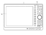
最初に、測定装置の一例としての波形表示装置1の構成について、図面を参照して説明する。図1に示す波形表示装置1は、同図および図2に示すように、測定部11、表示部12、操作部13、制御部14および記録部15を備えて構成されている。
First, the configuration of the
測定部11は、制御部14の制御に従い、入力した電気信号Se(一例として、電圧信号)の物理量(この例では、電圧)を測定して測定データDwを出力する。表示部12は、一例として、液晶パネルで構成されて、制御部14の制御に従い、制御部14によって生成される表示用データDdに基づく画像(後述するグラフG、目盛線L1および経過時間情報Itなど)を表示する。操作部13は、モード切替えキー、記録開始キーおよび記録終了キーなどを備えて構成され、これらが操作されたときに操作信号So(図2参照)を出力する。
Under the control of the
制御部14は、操作部13から出力される操作信号Soに従って波形表示装置1を構成する各部に対する制御や、各種の処理を実行する。具体的には、制御部14は、測定部11による物理量の測定(測定処理)を制御すると共に、記録部15への測定データDwの記録や、記録部15からの測定データDwの読み出しを行う。
The
また、制御部14は、表示制御部として機能し、表示用データDdを生成して表示部12に出力することにより、各種の画像を表示部12に表示させる。具体的には、制御部14は、図3に示すように、時間軸Ax(同図では横軸)および電圧軸Ay(同図では縦軸)を表示させる。また、制御部14は、測定部11による電圧の測定開始時点からの経過時間Tを示す目盛(スケール)としての目盛線L1を時間軸Axに直交するようにして複数表示させる。また、制御部14は、隣接する2つの目盛線L1の間隔に対応する時間が区切りのよい時間となるように目盛線L1を表示させる。この場合、時間軸Axの長さ(時間軸Axの一端から他端までに対応する時間の長短)によっては、目盛線L1の数が少な過ぎて、目盛線L1が有効に機能しないことがある。このため、制御部14は、図7に示すように、目盛線L1の数が予め決められた数(例えば4本)以下のときには、隣接する目盛線L1の間(具体的には、隣接する目盛線L1の真中)に目盛線L1に平行な目盛補助線L2を表示させる。また、制御部14は、電圧値を示す文字情報Ivを電圧軸Ayに沿って表示させる
Further, the
また、制御部14は、図3〜図7に示すように、測定部11によって測定された電気信号Seにおける電圧の経時変化を示すグラフG(言い替えると、電気信号Seの波形)を表示させる。また、この波形表示装置1では、時間軸Ax方向(各図における横方向)および電圧軸Ay方向(各図における縦方向)にグラフGを任意に拡縮(拡大および縮小)して表示させることが可能となっている。この場合、グラフGを拡縮して表示させる際の操作方法としては、表示されているグラフGの一部の範囲を図外のポインティングデバイスを用いて指定したり、2つの経過時間Tを入力して範囲を指定したりして、制御部14が指定した部分を画面一杯に表示させる方法などを採用することができる。
Moreover, the
また、制御部14は、図3〜図7に示すように、各目盛線L1に対応する経過時間Tを示す経過時間情報Itを表示させる。この場合、経過時間情報Itは、各図に示すように、時間の単位を表す時間単位表記(これらの例では、「日」を表す「d」、「時間」を表す「h」、「分」を表す「m」、「秒」を表す「s」)と、これらの時間単位表記に対応する時間の長さを表す整数(小数点以下を含まない数)とを用いて構成されている。また、制御部14は、経過時間情報Itを表示させる際に、後述する設定処理を実行することにより、経過時間情報Itに用いる最小の時間単位表記(最も短い時間を表す時間単位表記)を時間軸Axの時間長Tm(表示部12に表示されている時間軸Axの一端から他端までに対応する時間の長さ)に応じて設定(変更)する。
Moreover, the
記録部15は、制御部14の制御に従い、測定部11から出力された測定データDwを記録する。また、記録部15には、制御部14によって実行される設定処理において用いられる複数の判定範囲Rについてのデータ、および各判定範囲Rに1つずつ対応付けられた時間単位表記についてのデータが記録されている。この場合、判定範囲Rは時間軸Axの時間長Tmの長短を判定するために時間長Tmの上限値および下限値の少なくとも一方で規定された範囲であって、この波形表示装置1では、4つの判定範囲R1〜R4が規定されている。
The
具体的には、この波形表示装置1では、一例として、判定範囲R1として0秒〜3分(180秒)が設定され、判定範囲R2として3分〜3時間(180分)が設定され、判定範囲R3として3時間〜3日(72時間)が設定され、判定範囲R4として3日以上が設定されている。また、この波形表示装置1では、「日」を表す時間単位表記としての「d」が判定範囲R4に対応付けられ、「時間」を表す時間単位表記としての「h」が判定範囲R3に対応付けられて、「分」を表す時間単位表記としての「m」が判定範囲R2に対応付けられ、「秒」を表す時間単位表記としての「s」が判定範囲R1に対応付けられている。
Specifically, in this
次に、波形表示装置1を用いて電気信号Seにおける電圧の経時変化を示すグラフGを表示させる方法、およびその際の波形表示装置1の動作について、図面を参照して説明する。
Next, a method for displaying a graph G showing a change in voltage over time in the electric signal Se using the
まず、操作部13のモード切替えキーを操作して、波形表示装置1を記録モードに切り替えた後に、操作部13の記録開始キーを操作する。この際に、制御部14が、操作部13から出力された操作信号Soに従って測定部11を制御し、測定部11が、制御部14の制御に従い、入力した電気信号Se(一例として、電圧信号)の物理量(この例では、電圧)を測定して測定データDwを出力する測定処理を開始する。
First, after operating the mode switching key of the
次いで、制御部14は、測定部11から出力された測定データDwを記録部15に記録させる。続いて、電気信号Seの記録を終了する際には、操作部13の記録終了キーを操作する。これに応じて、制御部14は、測定部11を制御して測定処理を停止させると共に、記録部15を制御して測定データDwの記録を終了させる。
Next, the
次に、記録部15に記録した測定データDwに基づく電気信号Seにおける電圧の経時変化を示すグラフG(電気信号Seの波形)を表示させる。具体的には、操作部13のモード切替えキーを操作して、波形表示装置1を波形表示モードに切り替える。この際に、制御部14は、操作部13から出力された操作信号Soに従い、記録部15から測定データDwを読み出す。次いで、制御部14は、読み出した測定データDwに基づき、記録開始時点から記録終了時点までに亘る電圧の経時変化を示すグラフG(以下、このグラフGを「グラフG1」ともいう)を表示させるための表示用データDdを生成して表示部12に出力する。また、制御部14は、時間軸Ax、電圧軸Ay、文字情報Iv、目盛線L1および経過時間情報Itを表示させるための表示用データDdを生成して表示部12に出力する。これにより、図3に示すように、グラフG1、時間軸Ax、電圧軸Ay、文字情報Iv、目盛線L1および経過時間情報Itが表示部12に表示される。
Next, a graph G (waveform of the electric signal Se) showing the change over time of the voltage in the electric signal Se based on the measurement data Dw recorded in the
ここで、制御部14は、経過時間情報Itを表示させるための表示用データDdの生成に当たり、経過時間情報Itに用いる最小の時間単位表記を時間軸Axの時間長Tmに応じて設定する設定処理を実行する。この設定処理では、制御部14は、時間軸Axの時間長Tmが、上記した4つの判定範囲R1〜R4のうちのどの判定範囲Rに属するかを特定し、特定した判定範囲Rに対応付けられている時間単位表記を経過時間情報Itに用いる最小の時間単位表記として設定する。
Here, in generating the display data Dd for displaying the elapsed time information It, the
この例では、記録開始時点から記録終了時点までの経過時間Tが7日程度であるため(図3参照)、制御部14は、設定処理において、時間軸Axの時間長Tmが判定範囲R4に属していると特定し、特定した判定範囲R4に対応付けられている「d」を経過時間情報Itに用いる最小の時間単位表記として設定する。また、制御部14は、同図に示すように、設定した最小の時間単位表記である「d」よりも短い時間を示す時間単位表記である「h」、「m」および「s」、並びに「h」、「m」および「s」に対応する時間の長さを表す整数を除外した(つまり、「日」よりも短い時間を切り捨てた)形態での経過時間情報Itを各目盛線L1の下部に表示させる。
In this example, since the elapsed time T from the recording start time to the recording end time is about 7 days (see FIG. 3), the
続いて、グラフG1の一部を拡大して表示させる際には、図外のポインティングデバイスを用いて、図3に示すように、表示部12に表示されているグラフG1における拡縮させる範囲を指定し、次いで、その指定した範囲を拡大させるようにドラッグ操作を行う。これに応じて、制御部14は、指定した範囲に対応する測定データDwに基づき、その範囲を拡大して表示させるための表示用データDdを生成して表示部12に出力する。また、制御部14は、時間軸Ax、電圧軸Ay、文字情報Ivおよび目盛線L1および経過時間情報Itを表示させるための表示用データDdを生成して表示部12に出力する。これにより、図4に示すように、グラフG1における指定範囲を拡大したグラフG(以下このグラフGを「グラフG2」ともいう)が、時間軸Ax、電圧軸Ay、文字情報Iv、目盛線L1および経過時間情報Itと共に表示される。
Subsequently, when a part of the graph G1 is enlarged and displayed, a range to be enlarged or reduced in the graph G1 displayed on the
この場合、制御部14は、グラフGの拡大に伴って時間軸Axの時間長Tmが変化するため、設定処理を実行して経過時間情報Itに用いる最小の時間単位表記を新たに設定(変更)する。この例では、時間軸Axの経過時間Tが7時間程度であるため(図4参照)、制御部14は、設定処理において、時間軸Axの時間長Tmが判定範囲R3に属していると特定し、特定した判定範囲R3に対応付けられている「h」を経過時間情報Itに用いる最小の時間単位表記として設定する。また、制御部14は、同図に示すように、設定した最小の時間単位表記である「h」よりも短い時間を示す時間単位表記である「m」および「s」、並びに「m」および「s」に対応する時間の長さを表す整数を除外した(つまり、「時間」よりも短い時間を切り捨てた)形態での経過時間情報Itを各目盛線L1の下部に表示させる。
In this case, since the time length Tm of the time axis Ax changes as the graph G is enlarged, the
続いて、さらにグラフG2の一部を拡大して表示させる際には、図4に示すように、グラフG2における拡縮させる範囲を指定してドラッグ操作を行う。これに応じて、制御部14が表示用データDdを表示部12に出力することにより、図5に示すように、グラフG2における指定範囲を拡大したグラフG(以下このグラフGを「グラフG3」ともいう)が時間軸Ax、電圧軸Ay、文字情報Iv、目盛線L1および経過時間情報Itと共に表示される。
Subsequently, when a part of the graph G2 is enlarged and displayed, a drag operation is performed by designating a range to be enlarged or reduced in the graph G2, as shown in FIG. In response to this, the
この場合、時間軸Axの経過時間Tが7分程度であるため(図5参照)、制御部14は、設定処理において、時間軸Axの時間長Tmが判定範囲R2に属していると特定し、特定した判定範囲R2に対応付けられている「m」を経過時間情報Itに用いる最小の時間単位表記として設定する。また、制御部14は、同図に示すように、設定した最小の時間単位表記である「m」よりも短い時間を示す時間単位表記である「s」、および「s」に対応する時間の長さを表す整数を除外した(つまり、「分」よりも短い時間を切り捨てた)形態での経過時間情報Itを各目盛線L1の下部に表示させる。
In this case, since the elapsed time T of the time axis Ax is about 7 minutes (see FIG. 5), the
次いで、さらにグラフG3の一部を拡大して表示させる際には、図5に示すように、グラフG3における拡縮させる範囲を指定してドラッグ操作を行う。これに応じて、制御部14が表示用データDdを表示部12に出力することにより、図6に示すように、グラフG3における指定範囲を拡大したグラフG(以下このグラフGを「グラフG4」ともいう)が時間軸Ax、電圧軸Ay、文字情報Iv、目盛線L1および経過時間情報Itと共に表示される。
Next, when a part of the graph G3 is further enlarged and displayed, a drag operation is performed by designating a range to be enlarged or reduced in the graph G3 as shown in FIG. In response to this, the
この場合、時間軸Axの経過時間Tが35秒程度であるため(図6参照)、制御部14は、設定処理において、時間軸Axの時間長Tmが判定範囲R1に属していると特定し、特定した判定範囲R1に対応付けられている「s」を経過時間情報Itに用いる最小の時間単位表記として設定し、同図に示すように、「s」、「m」、「h」、および「s」、「m」、「h」にそれぞれ対応する時間の長さを表す整数を用いて表した経過時間情報Itを各目盛線L1の下部に表示させる。
In this case, since the elapsed time T of the time axis Ax is about 35 seconds (see FIG. 6), the
上記したように、この波形表示装置1では、経過時間情報Itに用いる最小の時間単位表記が、時間軸Axの時間長Tmが長いほど長い時間を示す時間単位表記に設定され、時間長Tmが短いほど短い時間を示す時間単位表記に設定される。また、設定した最小の時間単位表記よりも短い時間を示す時間単位表記およびその時間単位表記に対応する時間の長さを表す整数を除外した(つまり、その時間単位表記よりも短い時間を切り捨てた)形態での経過時間情報Itが表示される。これにより、時間軸Axの時間長Tmが長いときおよび短いときのいずれのときにおいても、短い桁数の経過時間情報Itが表示される。このため、この波形表示装置1では、時間軸Axの時間長Tmの長短に拘わらず経過時間情報Itの見易さが十分に向上されている。
As described above, in the
一方、例えば、隣接する2つの目盛線L1の間の時間を5秒とするように規定されている場合において、図7に示すように、グラフG5を拡大表示させた結果、時間軸Axの時間長Tmが15秒程度となったときには、表示部12には、目盛線L1が4本だけ表示されることとなる。このように目盛線L1の数が少ないときには、例えば、グラフG5の極大点が現れる経過時間Tを、目盛線L1を目安にして特定するような態様において、目盛線L1が有効に機能しないことがある。このため、制御部14は、目盛線L1の数が予め決められた本数としての4本以下のときには、同図に示すように、隣接する目盛線L1の間(具体的には、隣接する目盛線L1の真中)に目盛線L1に平行な目盛補助線L2を表示させる。この波形表示装置1では、この機能を備えているため、目盛線L1の数が少ない場合においても、目盛補助線L2を目安として用いることで上記のような特定作業を容易に行うことが可能となっている。
On the other hand, for example, in the case where the time between two adjacent graduation lines L1 is defined to be 5 seconds, as shown in FIG. 7, as a result of enlarging the graph G5, the time on the time axis Ax When the length Tm is about 15 seconds, only four scale lines L1 are displayed on the
このように、この波形表示装置1および経過時間表示方法によれば、経過時間情報Itに用いる最小の時間単位表記を、時間軸Axの時間長Tmが長いほど長い時間を示す時間単位表記に設定し、設定した最小の時間単位表記よりも短い時間を示す時間単位表記およびその時間単位表記に対応する時間の長さを表す整数を除外した形態での経過時間情報Itを表示させることにより、時間軸Axの時間長Tmが数日に及ぶほど長いときには、長い時間を示す時間単位表記を最小の時間単位表記として用いた短い桁数の経過時間情報Itを表示させ、時間軸Axの時間長Tmが数秒程度の短いときには、短い時間を示す時間単位表記を用いて小数点以下の表示を除外した経過時間情報Itを表示させることができる。したがって、この波形表示装置1および経過時間表示方法によれば、時間軸Axの時間長Tmの長短に拘わらず経過時間情報Itの見易さを十分に向上させることができるため、経過時間Tを一目で把握させることができると共に、隣接する目盛線L1の間隔(その間隔に対応する時間)を即座に把握させることができる。また、この波形表示装置1によれば、最小の時間単位表記を設定する設定処理を制御部14が行うことにより、設定作業を手動で行う必要がないため、例えば、表示倍率を頻繁に変更する使用形態における操作性を十分に向上することができる。
Thus, according to the
また、この波形表示装置1および経過時間表示方法によれば、時間軸Axの時間長Tmが属する判定範囲Rを特定すると共に、特定した判定範囲Rに対応付けられている時間単位表記を経過時間情報Itに用いる最小の時間単位表記として設定することにより、例えば、判定範囲R、および判定範囲Rに対応付ける時間単位表記を使用形態に応じて予め規定しておくことで、使用形態に応じて最適な最小の時間単位表記を自動的に設定することができるため、利便性を十分に高めることができる。
Further, according to the
また、この波形表示装置1および経過時間表示方法によれば、目盛線L1の数が予め決められた数以下のときに、隣接する目盛線L1の間(上記の例では、隣接する目盛線L1の真中)に目盛線L1に平行な目盛補助線L2を表示させることにより、例えば、グラフG5の極大点が現れる経過時間Tを特定する作業を行う作業形態において、目盛線L1の数が少ないことに起因してその特定作業が困難な場合においても、目盛補助線L2を目安とすることで、その特定作業を容易に行うことができる。
Further, according to the
なお、波形表示装置1および経過時間表示方法は上記の構成および方法に限定されない。例えば、時間の単位を表す時間単位表記として、「d」、「h」、「m」、「s」を用いる例について上記したが、「月」を表す時間単位表記や、「年」表す時間単位表記を用いる構成および方法を採用することができる。また、1/1000を表す「m」や1/1000000を表す「μ」などのSI接頭辞を上記「s」に付した時間単位表記(「ms」や「μs」)を用いる構成および方法を採用することもできる。
The
また、制御部14が設定処理を行う構成例、つまり経過時間情報Itに用いる最小の時間単位表記を自動的に設定する構成例について上記したが、最小の時間単位表記を手動で設定する構成を採用することができる。この場合、この構成によれば、表示部12に表示されている時間軸Axの時間長Tmの長短に拘わらず、手動で設定した時間単位表記を最小の時間単位表記として用いた経過時間情報Itを表示させることができる。
In addition, the configuration example in which the
また、表示部12を備えた波形表示装置1に適用した例について上記したが、表示部12を備えていない測定装置に適用することができる。この場合、パーソナルコンピュータ(例えば、ノート型のパーソナルコンピュータ)の表示部に表示用データDdに基づくグラフG、目盛線L1および経過時間情報Itなどの画像を表示させる構成を採用することができる。また、パーソナルコンピュータを制御部14として機能させる構成や、パーソナルコンピュータを制御部14および記録部15として機能させる構成を採用することもできる。
Moreover, although it described above about the example applied to the
また、電気信号Seとしての電圧信号における電圧の経時変化を示すグラフG(電気信号Seの波形)を表示させる例について上記したが、電圧に限らず、電流、電力、抵抗、インピーダンスおよび温度などの各種の物理量の経時変化を示すグラフGを表示させる際に適用することができるのは勿論である。 Further, the example of displaying the graph G (the waveform of the electric signal Se) indicating the change over time of the voltage in the voltage signal as the electric signal Se has been described above. However, not only the voltage but also current, power, resistance, impedance, temperature, etc. Needless to say, the present invention can be applied to display a graph G showing changes in various physical quantities over time.
また、2つの以上の時間単位表記を用いて経過時間情報Itを構成する場合において、最小の時間単位表記よりも長い時間を示す時間単位表記に対応する時間の長さを表す整数が「0」のときには、その時間単位表記およびその「0」を除外した態様で経過時間情報Itを表示する構成および方法を採用することもできる。この構成および方法を採用したときには、例えば、時間単位表記として「時間」「分」「秒」を用いる場合において、経過時間Tが3時間0分21秒のときには、「分」および「0」が除外された「3時間21秒」との経過時間情報Itを表示させることができるため、経過時間情報Itを十分に見易く表示することができる。 In the case where the elapsed time information It is configured using two or more time unit notations, an integer representing a time length corresponding to the time unit notation indicating a time longer than the minimum time unit notation is “0”. In this case, a configuration and a method for displaying the elapsed time information It in a mode excluding the time unit notation and the “0” may be employed. When this configuration and method are adopted, for example, when “hour”, “minute”, and “second” are used as the time unit notation, when the elapsed time T is 3 hours, 0 minutes, and 21 seconds, “minutes” and “0” are Since the elapsed time information It with the excluded “3 hours 21 seconds” can be displayed, the elapsed time information It can be displayed sufficiently easily.
1 波形表示装置
11 測定部
13 表示部
14 制御部
Ax 時間軸
G1〜G5 グラフ
It 経過時間情報
L1 目盛線
L2 目盛補助線
R1〜R4 判定範囲
DESCRIPTION OF
Claims (6)
前記表示制御部は、前記経過時間情報に用いる最小の前記時間単位表記を前記表示部に表示されている前記時間軸の時間長が長いほど長い時間を示す時間単位表記に設定する設定処理を実行し、当該最小の時間単位表記よりも短い時間を示す時間単位表記および当該時間単位表記に対応する前記整数を除外した前記経過時間情報を表示させる測定装置。 A graph showing the change over time of the measured physical quantity is displayed on the display unit in a time scale direction, and a scale indicating the elapsed time from the measurement start time of the physical quantity, and a time unit notation indicating the unit of time and the time A display control unit that causes the display unit to display elapsed time information indicating the elapsed time corresponding to the scale using an integer representing a length of time corresponding to the unit notation;
The display control unit executes a setting process for setting the minimum time unit notation used for the elapsed time information to a time unit notation indicating a longer time as the time length of the time axis displayed on the display unit is longer And a time unit notation indicating a time shorter than the minimum time unit notation and the elapsed time information excluding the integer corresponding to the time unit notation.
前記表示制御部は、前記設定処理において、前記表示部に表示されている前記時間軸の時間長が属する前記判定範囲を特定すると共に、当該特定した判定範囲に対応付けられている前記時間単位表記を前記経過時間情報に用いる前記最小の時間単位表記として設定する請求項1記載の測定装置。 A plurality of determination ranges for determining the length of the time length of the time axis are defined, and the time unit notation is defined in association with each determination range one by one,
In the setting process, the display control unit specifies the determination range to which the time length of the time axis displayed on the display unit belongs, and the time unit notation associated with the specified determination range The measurement apparatus according to claim 1, wherein the minimum time unit notation used for the elapsed time information is set.
前記経過時間情報に用いる最小の前記時間単位表記を前記表示部に表示されている前記時間軸の時間長が長いほど長い時間を示す時間単位表記に設定する設定処理を実行し、当該最小の時間単位表記よりも短い時間を示す時間単位表記および当該時間単位表記に対応する前記整数を除外した前記経過時間情報を表示させる経過時間表示方法。 A graph showing the change over time of the measured physical quantity is displayed on the display unit in a time scale direction, and a scale indicating the elapsed time from the measurement start time of the physical quantity, and a time unit notation indicating the unit of time and the time When displaying the elapsed time information indicating the elapsed time corresponding to the scale using an integer representing the length of time corresponding to the unit notation on the display unit,
The minimum time unit notation used for the elapsed time information is set to a time unit notation indicating a longer time as the time length of the time axis displayed on the display unit is longer, and the minimum time is executed. An elapsed time display method for displaying a time unit notation indicating a time shorter than the unit notation and the elapsed time information excluding the integer corresponding to the time unit notation.
前記設定処理において、前記表示部に表示されている前記時間軸の時間長が属する前記判定範囲を特定すると共に、当該特定した判定範囲に対応付けている前記時間単位表記を前記経過時間情報に用いる前記最小の時間単位表記として設定する請求項4記載の経過時間表示方法。 Defining a plurality of determination ranges for determining the length of the time length of the time axis, and defining the time unit notation in association with each determination range one by one,
In the setting process, the determination range to which the time length of the time axis displayed on the display unit belongs is specified, and the time unit notation associated with the specified determination range is used for the elapsed time information. The elapsed time display method according to claim 4, wherein the elapsed time display is set as the minimum time unit notation.
Priority Applications (1)
| Application Number | Priority Date | Filing Date | Title |
|---|---|---|---|
| JP2010125747A JP5456581B2 (en) | 2010-06-01 | 2010-06-01 | Measuring apparatus and elapsed time display method |
Applications Claiming Priority (1)
| Application Number | Priority Date | Filing Date | Title |
|---|---|---|---|
| JP2010125747A JP5456581B2 (en) | 2010-06-01 | 2010-06-01 | Measuring apparatus and elapsed time display method |
Publications (2)
| Publication Number | Publication Date |
|---|---|
| JP2011252750A JP2011252750A (en) | 2011-12-15 |
| JP5456581B2 true JP5456581B2 (en) | 2014-04-02 |
Family
ID=45416804
Family Applications (1)
| Application Number | Title | Priority Date | Filing Date |
|---|---|---|---|
| JP2010125747A Active JP5456581B2 (en) | 2010-06-01 | 2010-06-01 | Measuring apparatus and elapsed time display method |
Country Status (1)
| Country | Link |
|---|---|
| JP (1) | JP5456581B2 (en) |
Families Citing this family (1)
| Publication number | Priority date | Publication date | Assignee | Title |
|---|---|---|---|---|
| JP2015232433A (en) * | 2014-05-14 | 2015-12-24 | アイリスオーヤマ株式会社 | Air cleaner |
Family Cites Families (3)
| Publication number | Priority date | Publication date | Assignee | Title |
|---|---|---|---|---|
| US4764721A (en) * | 1987-03-24 | 1988-08-16 | Tektronix, Inc. | Locking scales to waveform displays |
| JP4254193B2 (en) * | 2002-10-10 | 2009-04-15 | 横河電機株式会社 | Measuring apparatus and display method of measurement result |
| JP5165355B2 (en) * | 2007-12-13 | 2013-03-21 | 日置電機株式会社 | Measurement data recording apparatus and measurement data recording method |
-
2010
- 2010-06-01 JP JP2010125747A patent/JP5456581B2/en active Active
Also Published As
| Publication number | Publication date |
|---|---|
| JP2011252750A (en) | 2011-12-15 |
Similar Documents
| Publication | Publication Date | Title |
|---|---|---|
| JP6608579B2 (en) | Measuring instrument | |
| JP5135890B2 (en) | Waveform measuring device | |
| JP5456581B2 (en) | Measuring apparatus and elapsed time display method | |
| JP5154236B2 (en) | Measuring device and display method of setting screen | |
| JP4280998B2 (en) | Portable measuring instrument and display method thereof | |
| JP2002082133A (en) | Waveform display device | |
| JP5319201B2 (en) | Waveform observation device | |
| JP2011027673A (en) | Device and method for displaying measurement result | |
| JP5599378B2 (en) | Display control device | |
| JP5025956B2 (en) | Display control device | |
| JP5115786B2 (en) | Waveform display device | |
| JP5358946B2 (en) | Electronic device and program with graph display function | |
| CN107018673B (en) | Information obtains display program, information obtains display device and information obtains display methods | |
| JP2005300408A (en) | Waveform display unit | |
| JP4665955B2 (en) | Display device | |
| JP5496781B2 (en) | Waveform display device and waveform display method | |
| JP2011106854A (en) | Measuring instrument | |
| JP6656592B2 (en) | Waveform display device | |
| JP2007132672A (en) | Recorder | |
| JP5362257B2 (en) | Waveform recorder | |
| JP5399286B2 (en) | Measuring equipment | |
| JP5599377B2 (en) | Display control device | |
| JPH11281405A (en) | Display method in measuring device and measuring device | |
| JP2014163931A (en) | Measurement control device | |
| JP2017072452A (en) | Display device, measuring device, display method, and program |
Legal Events
| Date | Code | Title | Description |
|---|---|---|---|
| A621 | Written request for application examination |
Free format text: JAPANESE INTERMEDIATE CODE: A621 Effective date: 20130419 |
|
| A977 | Report on retrieval |
Free format text: JAPANESE INTERMEDIATE CODE: A971007 Effective date: 20131226 |
|
| TRDD | Decision of grant or rejection written | ||
| A01 | Written decision to grant a patent or to grant a registration (utility model) |
Free format text: JAPANESE INTERMEDIATE CODE: A01 Effective date: 20140107 |
|
| A61 | First payment of annual fees (during grant procedure) |
Free format text: JAPANESE INTERMEDIATE CODE: A61 Effective date: 20140108 |
|
| R150 | Certificate of patent or registration of utility model |
Ref document number: 5456581 Country of ref document: JP Free format text: JAPANESE INTERMEDIATE CODE: R150 Free format text: JAPANESE INTERMEDIATE CODE: R150 |
|
| R250 | Receipt of annual fees |
Free format text: JAPANESE INTERMEDIATE CODE: R250 |
|
| R250 | Receipt of annual fees |
Free format text: JAPANESE INTERMEDIATE CODE: R250 |
|
| R250 | Receipt of annual fees |
Free format text: JAPANESE INTERMEDIATE CODE: R250 |
|
| R250 | Receipt of annual fees |
Free format text: JAPANESE INTERMEDIATE CODE: R250 |