JP5455575B2 - Recording device - Google Patents
Recording device Download PDFInfo
- Publication number
- JP5455575B2 JP5455575B2 JP2009262072A JP2009262072A JP5455575B2 JP 5455575 B2 JP5455575 B2 JP 5455575B2 JP 2009262072 A JP2009262072 A JP 2009262072A JP 2009262072 A JP2009262072 A JP 2009262072A JP 5455575 B2 JP5455575 B2 JP 5455575B2
- Authority
- JP
- Japan
- Prior art keywords
- nozzle
- suction
- suction means
- blade
- chip
- Prior art date
- Legal status (The legal status is an assumption and is not a legal conclusion. Google has not performed a legal analysis and makes no representation as to the accuracy of the status listed.)
- Active
Links
- 238000007789 sealing Methods 0.000 claims description 23
- 239000000758 substrate Substances 0.000 claims description 17
- 239000006096 absorbing agent Substances 0.000 claims description 9
- 238000004140 cleaning Methods 0.000 description 33
- 230000007246 mechanism Effects 0.000 description 21
- 239000000428 dust Substances 0.000 description 15
- 238000006073 displacement reaction Methods 0.000 description 9
- 238000000034 method Methods 0.000 description 5
- 238000010586 diagram Methods 0.000 description 4
- 239000003086 colorant Substances 0.000 description 3
- 238000001035 drying Methods 0.000 description 3
- 230000015572 biosynthetic process Effects 0.000 description 2
- 239000011358 absorbing material Substances 0.000 description 1
- 238000010521 absorption reaction Methods 0.000 description 1
- 239000003570 air Substances 0.000 description 1
- 238000005260 corrosion Methods 0.000 description 1
- 230000007797 corrosion Effects 0.000 description 1
- 238000007599 discharging Methods 0.000 description 1
- 238000010438 heat treatment Methods 0.000 description 1
- 239000000463 material Substances 0.000 description 1
- 238000007639 printing Methods 0.000 description 1
- 238000011084 recovery Methods 0.000 description 1
- 239000011347 resin Substances 0.000 description 1
- 229920005989 resin Polymers 0.000 description 1
- 238000007790 scraping Methods 0.000 description 1
- 230000007723 transport mechanism Effects 0.000 description 1
Images


Classifications
-
- B—PERFORMING OPERATIONS; TRANSPORTING
- B41—PRINTING; LINING MACHINES; TYPEWRITERS; STAMPS
- B41J—TYPEWRITERS; SELECTIVE PRINTING MECHANISMS, i.e. MECHANISMS PRINTING OTHERWISE THAN FROM A FORME; CORRECTION OF TYPOGRAPHICAL ERRORS
- B41J2/00—Typewriters or selective printing mechanisms characterised by the printing or marking process for which they are designed
- B41J2/005—Typewriters or selective printing mechanisms characterised by the printing or marking process for which they are designed characterised by bringing liquid or particles selectively into contact with a printing material
- B41J2/01—Ink jet
- B41J2/135—Nozzles
- B41J2/165—Prevention or detection of nozzle clogging, e.g. cleaning, capping or moistening for nozzles
- B41J2/16517—Cleaning of print head nozzles
- B41J2/1652—Cleaning of print head nozzles by driving a fluid through the nozzles to the outside thereof, e.g. by applying pressure to the inside or vacuum at the outside of the print head
- B41J2/16532—Cleaning of print head nozzles by driving a fluid through the nozzles to the outside thereof, e.g. by applying pressure to the inside or vacuum at the outside of the print head by applying vacuum only
-
- B—PERFORMING OPERATIONS; TRANSPORTING
- B41—PRINTING; LINING MACHINES; TYPEWRITERS; STAMPS
- B41J—TYPEWRITERS; SELECTIVE PRINTING MECHANISMS, i.e. MECHANISMS PRINTING OTHERWISE THAN FROM A FORME; CORRECTION OF TYPOGRAPHICAL ERRORS
- B41J2/00—Typewriters or selective printing mechanisms characterised by the printing or marking process for which they are designed
- B41J2/005—Typewriters or selective printing mechanisms characterised by the printing or marking process for which they are designed characterised by bringing liquid or particles selectively into contact with a printing material
- B41J2/01—Ink jet
- B41J2/135—Nozzles
- B41J2/165—Prevention or detection of nozzle clogging, e.g. cleaning, capping or moistening for nozzles
- B41J2/16517—Cleaning of print head nozzles
- B41J2/16535—Cleaning of print head nozzles using wiping constructions
- B41J2/16544—Constructions for the positioning of wipers
- B41J2/16547—Constructions for the positioning of wipers the wipers and caps or spittoons being on the same movable support
-
- B—PERFORMING OPERATIONS; TRANSPORTING
- B41—PRINTING; LINING MACHINES; TYPEWRITERS; STAMPS
- B41J—TYPEWRITERS; SELECTIVE PRINTING MECHANISMS, i.e. MECHANISMS PRINTING OTHERWISE THAN FROM A FORME; CORRECTION OF TYPOGRAPHICAL ERRORS
- B41J2/00—Typewriters or selective printing mechanisms characterised by the printing or marking process for which they are designed
- B41J2/005—Typewriters or selective printing mechanisms characterised by the printing or marking process for which they are designed characterised by bringing liquid or particles selectively into contact with a printing material
- B41J2/01—Ink jet
- B41J2/135—Nozzles
- B41J2/165—Prevention or detection of nozzle clogging, e.g. cleaning, capping or moistening for nozzles
- B41J2/16585—Prevention or detection of nozzle clogging, e.g. cleaning, capping or moistening for nozzles for paper-width or non-reciprocating print heads
-
- B—PERFORMING OPERATIONS; TRANSPORTING
- B41—PRINTING; LINING MACHINES; TYPEWRITERS; STAMPS
- B41J—TYPEWRITERS; SELECTIVE PRINTING MECHANISMS, i.e. MECHANISMS PRINTING OTHERWISE THAN FROM A FORME; CORRECTION OF TYPOGRAPHICAL ERRORS
- B41J2/00—Typewriters or selective printing mechanisms characterised by the printing or marking process for which they are designed
- B41J2/005—Typewriters or selective printing mechanisms characterised by the printing or marking process for which they are designed characterised by bringing liquid or particles selectively into contact with a printing material
- B41J2/01—Ink jet
- B41J2/135—Nozzles
- B41J2/165—Prevention or detection of nozzle clogging, e.g. cleaning, capping or moistening for nozzles
- B41J2/16517—Cleaning of print head nozzles
- B41J2/16535—Cleaning of print head nozzles using wiping constructions
- B41J2/16541—Means to remove deposits from wipers or scrapers
Landscapes
- Ink Jet (AREA)
Description
本発明はライン型記録ヘッドを用いたインクジェット方式の記録装置に関する The present invention relates to an ink jet recording apparatus using a line type recording head.
インクジェット方式の記録装置においては、ヘッドのノズル内のインクが乾燥して増粘・固着することがある。またノズル内のインクに紙粉や塵埃や気泡等が混入するなど、目詰まりに起因するインク吐出不良により記録品質の低下が生じることがある。そのため、記録ヘッドのクリーニングが必要である。 In an ink jet recording apparatus, the ink in the nozzles of the head may be dried and thickened or fixed. Further, the recording quality may be deteriorated due to ink ejection failure caused by clogging, such as paper dust, dust, air bubbles, etc. mixed in the ink in the nozzle. Therefore, the recording head needs to be cleaned.
特許文献1には、記録ヘッドから強制的にインクを吸引して回復を図るクリーニング機構が開示される。このクリーニング機構は、記録ヘッドの全ノズル列の長さよりも短い吸引口を備え、吸引口をノズル列の形成方向に移動させながらノズル全体の吸引を行なう。
複数のノズルチップを千鳥配列のように規則的に配置したライン型記録ヘッドが知られる。通常、千鳥配列の各列において隣り合うノズルチップの間には所定の隙間が設けられている。この隙間がノズル面とは異なる高さを持っている場合がある。例えば、図5に示すように、電極保護のためノズル面122よりも盛り上がった凸部からなる封止部123を持っている場合がある。このような構造の記録ヘッドに対して、特許文献1の吸引機構を適用しようとすると、以下のような解決すべき課題を生じる。
A line type recording head in which a plurality of nozzle chips are regularly arranged in a staggered arrangement is known. Usually, a predetermined gap is provided between adjacent nozzle chips in each row of the staggered arrangement. The gap may have a height different from the nozzle surface. For example, as shown in FIG. 5, there may be a case where a
吸引口11がノズル列に沿って移動する最中、吸引口が高さの異なる封止部123を乗り越える際には吸引口11が持ち上がる。吸引口11が移動する方向において、あるノズルチップ列における封止部123の位置は、隣のノズルチップ列においてはノズル列121である。吸引口の一部があるノズルチップ列の封止部123に乗り上げると、吸引口11全体がつられて持ち上がり、隣のノズルチップ列のノズルと吸引口11との密着が不完全になり、吸引不良を引き起こす畏れがある。
While the
本発明は上述の技術的課題に鑑みてなされたものである。本発明の目的の一つは、複数のノズルチップを規則的に配置したライン型記録ヘッドのノズル面を、より確実にクリーニングすることができる記録装置の提供である。 The present invention has been made in view of the above technical problems. One of the objects of the present invention is to provide a recording apparatus that can more reliably clean the nozzle surface of a line type recording head in which a plurality of nozzle chips are regularly arranged.
本発明は、上記目的を達成するため、シートを第1方向に搬送する搬送手段と、前記第1方向と交差する第2方向に沿って複数のノズルが配列された第1ノズルチップが前記第2方向に沿って複数設けられた第1ノズルチップ群と、前記第2方向に沿って複数のノズルが配列された第2ノズルチップが前記第2方向に沿って複数設けられた第2ノズルチップ群と、が配された基板を有し、前記第1ノズルチップ群と前記第2ノズルチップ群は前記第1方向においてずれて配置され、かつ隣接する前記第1ノズルチップと前記第2ノズルチップは前記第2方向において所定量ずれて配置され、さらに前記第1ノズルチップの前記第2方向における両端部及び前記第2ノズルチップの前記第2方向における両端部に前記基板から突出した封止部が設けられた記録ヘッドと、を備える記録装置において、前記第1ノズルチップからインクを吸引するための第1吸引手段と、前記第2方向において前記第1吸引手段に対して前記所定量ずれて配され前記第2ノズルチップからインクを吸引するための第2吸引手段と、を有する吸引ホルダと、前記第1吸引手段及び前記第2吸引手段が前記基板に当接するように前記吸引ホルダを付勢する付勢部材と、を備え、前記吸引ホルダは前記付勢部材に付勢されることによって前記第1吸引手段及び前記第2吸引手段が前記基板に当接した状態のまま前記第2方向に移動し、かつ前記第1吸収手段及び前記第2吸収手段が前記封止部を乗り越えるときの動きが前記付勢部材によって吸収されることを特徴とする。 In order to achieve the above object, the present invention provides a conveying means for conveying a sheet in a first direction, and a first nozzle chip in which a plurality of nozzles are arranged along a second direction intersecting the first direction. A first nozzle chip group provided in a plurality along two directions, and a second nozzle chip provided with a plurality of second nozzle chips in which a plurality of nozzles are arranged in the second direction along the second direction And the first nozzle chip group and the second nozzle chip group are arranged to be shifted in the first direction, and the first nozzle chip and the second nozzle chip are adjacent to each other. Are arranged with a predetermined amount shifted in the second direction, and further, sealing portions projecting from the substrate at both ends of the first nozzle chip in the second direction and both ends of the second nozzle chip in the second direction. But And a first suction unit for sucking ink from the first nozzle tip, and a predetermined amount shifted from the first suction unit in the second direction. A suction holder having a second suction means for sucking ink from the second nozzle chip, and biasing the suction holder so that the first suction means and the second suction means are in contact with the substrate. a biasing member, wherein the suction holder remains the second direction state where the first suction means and said second suction means is in contact with the substrate by being urged in the biasing member move, and the movement of when the first absorbing means and the second absorbing means rides over the sealing portion and said Rukoto is absorbed by the urging member.
本発明によれば、複数のノズルチップを規則的に配置したライン型記録ヘッドのノズル面をより確実にクリーニングすることができる記録装置が実現する。 According to the present invention, a recording apparatus capable of more reliably cleaning the nozzle surface of a line type recording head in which a plurality of nozzle chips are regularly arranged is realized.
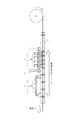
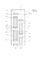
図面を参照して本発明の実施形態を具体的に説明する。図1は実施形態に係る記録装置の記録部を中心とした主要部の構成を示す斜視図であり、図2は図1の断面構造を示す断面図である。図3はクリーニング動作時の状態を示す断面図である。 Embodiments of the present invention will be specifically described with reference to the drawings. FIG. 1 is a perspective view showing a configuration of a main part centering on a recording part of a recording apparatus according to an embodiment, and FIG. 2 is a cross-sectional view showing a cross-sectional structure of FIG. FIG. 3 is a cross-sectional view showing a state during the cleaning operation.
本実施形態の記録装置は、長尺のラインヘッドを用いて、シートを搬送方向(第1方向)に連続搬送しながらプリントを行なうラインプリンタである。ロール状に巻かれた連続紙などのシート4を保持するホルダ、シート4を所定速度で第1方向に搬送する搬送機構7、シート4に対してラインヘッドで記録を行なう記録部3を備える。なお、シートは連続したロールシートに限らず、カットシートであってもよい。記録装置1は更に、記録ヘッドのノズル面をワイピングによってクリーニングするクリーニング部6を備える。さらに、シート搬送路に沿って、記録部3の下流にはシート4を切断するカッタユニット、シートを強制乾燥する乾燥ユニット、排出トレイを備えている。
The recording apparatus of the present embodiment is a line printer that performs printing while continuously conveying a sheet in the conveyance direction (first direction) using a long line head. A holder for holding a sheet 4 such as continuous paper wound in a roll shape, a transport mechanism 7 for transporting the sheet 4 in a first direction at a predetermined speed, and a
記録部3は、異なるインク色にそれぞれ対応した複数の記録ヘッド2を備える。本例ではCMYKの4色に対応した4つの記録ヘッドとしているが、色数はこれには限定されない。各色のインクはインクタンクからそれぞれインクチューブを介して記録ヘッド2に供給される。複数の記録ヘッド2はヘッドホルダ5で一体に保持されており複数の記録ヘッド2とシート4の表面との間の距離を変更できるよう、ヘッドホルダ5が上下移動することができる機構を有している。
The
クリーニング部6は、複数(4つ)の記録ヘッド2に対応して複数(4つ)のクリーニング機構9を有する。各クリーニング機構9の詳細は後述する。クリーニング部6は、ユニットごと第1方向にスライド移動可能な構成となっている。図1、図2は記録時の状態を示し、クリーニング部6は記録部3に対してシート搬送方向下流に位置している。一方、図3はクリーニング動作時の状態を示し、クリーニング部6は記録部3の記録ヘッド2の直下に位置している。図2、図3にクリーニング部6の移動可能範囲を矢印で示している。
The cleaning unit 6 includes a plurality (four) of cleaning mechanisms 9 corresponding to the plurality (four) of the
図4は1つの記録ヘッド2の構造を示す。インクジェット方式は、発熱素子を用いた方式、ピエゾ素子を用いた方式、静電素子を用いた方式、MEMS素子を用いた方式等を採用することができる。記録ヘッド2は、使用が想定されるシートの最大幅をカバーする範囲でインクジェット方式のノズル列が形成されたライン型記録ヘッドである。ノズル列の並び方向は、第1方向と交差する方向(第2方向)、例えば直交する方向である。大きなベース基板124の上に、複数のノズルチップ120が第2方向に沿って並んでいる。図4(b)に示すように、同一寸法且つ同一構造の複数(本例では12個)のノズルチップ120が2列の千鳥配列で規則的に幅方向全域に渡って形成されている。すなわち、記録ヘッド2は、それぞれがノズル列を有する複数の第1ノズルチップと複数の第2ノズルチップが、異なる列として第2方向に沿って並べられ、且つ隣接する前記第1ノズルチップと前記第2ノズルチップは前記第2方向でずれた位置関係となっている。隣接する第1ノズルチップと第2ノズルチップは、これらに含まれるノズル列の一部が、第2方向においてオーバーラップしている。
FIG. 4 shows the structure of one
図5は記録ヘッド2を構成するノズルチップ120の1つの構造を示す。ノズルチップ120は、インク吐出する複数のノズル列121が形成されたノズル面122を備えると共に、各ノズルに対応して形成されたエネルギ素子が埋め込まれているノズル基板を有する。複数(本例では4つ)のノズル列121は第1方向に4列平行に並んでいる。ノズルチップ120のノズル基板はベース基板124の上に設けられている。ノズル基板とベース基板124との間は電気接続部で接続され、電気接続部は樹脂材からなる封止部123で被覆され、腐食や断線が起きないように保護されている。図5(b)に示すように、ノズル面122を側方から見たとき、封止部123はベース基板124上に形成され、且つ、ノズル面122よりもインク吐出方向(第3方向という)に突出した凸部となっている。1つのノズルチップ120において、封止部123はノズル列の形成方向(第2方向)に関してノズル面122の両端2箇所の端部近傍に設けられている。このように、封止部123は複数のノズル列121に近接し、且つノズル面122よりもインク吐出方向になだらかな段差を持って突出するように盛り上がった形状を有している。
FIG. 5 shows one structure of the
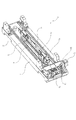
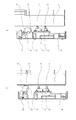
図7、図8は1つのクリーニング機構9の詳細構成を示す斜視図である。図7は記録ヘッドの下にクリーニング機構がある状態(クリーニング動作時)、図7は記録ヘッドの下にクリーニング機構がない状態(キャッピング時)である。 7 and 8 are perspective views showing the detailed configuration of one cleaning mechanism 9. FIG. 7 shows a state in which the cleaning mechanism is under the recording head (during cleaning operation), and FIG. 7 shows a state in which there is no cleaning mechanism under the recording head (during capping).
クリーニング機構9は、大ききくは、記録ヘッド2のノズル面に付着したインクおよびゴミを払拭するワイパユニット46と、ワイパユニット46を払拭方向(第2方向)に沿って移動させる移動機構、これらを一体に支持するフレーム47を有する。ワイパユニット46は後述するワイパブレードや吸引口が1つの移動可能なユニットとなっている。移動機構は、駆動源の駆動によって、2本のシャフト45によって案内支持されたワイパユニット46を第2方向に移動させる。駆動源は、駆動モータ41と減速ギア42、43を有し、ドライブシャフト37を回転させる。ドライブシャフト37の回転は、ベルト44とプーリで伝達されてワイパユニット46を移動させる。ワイパユニット46は、後述するようにブレードと吸引口の組み合わせによって、記録ヘッド2のノズル面のインクやゴミの除去を行なうものである。フレーム47のワイピング領域外には、後述するブレード21の向きの切り替えを行なうためにトリガレバー27が設けられている。
The cleaning mechanism 9 generally includes a
図8において、キャップ51はキャップホルダ52に保持されている。キャップホルダ52は記録ヘッド2のノズル面に対して垂直方向に弾性体であるバネで付勢され、バネに抗して移動可能となっている。フレーム47がキャップ位置にある状態で記録ヘッド2がノズル面に対して垂直方向に移動して、キャップ51と密着および離間を行なう。密着によってノズル面をキャッピングすることでノズルの乾燥が抑制される。
In FIG. 8, the
図9はワイパユニット46の構成を示す図である。第1、第2のノズルチップ列に対応して2つの吸引口11(第1、第2の吸引手段)が設けられている。2つの吸引口11は、第1方向においては2つのノズルチップ列の間隔と同じ間隔を有する。2つの吸引口11は、第2方向においては2つのノズルチップ列の隣り合うノズルチップの間のずれ量(所定距離)と同じかほぼ同じずれ量を有している。吸引口11は吸引ホルダ12に保持され、吸引ホルダ12は記録ヘッド2のノズル面に対して垂直方向(第3方向)に弾性体であるバネ14で付勢され、バネに抗して第3方向に移動可能となっている。更に、吸引ホルダ12は、第1方向における両端が軸支され、バネ14の付勢に抗して第1方向を回転軸として回転することも可能な構造となっている。つまり、吸引ホルダ12は、ノズル面とシートの間隔方向(第3方向)での直進変位と、第1方向を回転軸としたノズル面に対するチルト変位の両方の変位が可能となるよう、弾性体を有する変位機構によって支持されている。この変位機構は、移動中の吸引口11が封止部123を乗り越える際の動きを吸収するためのものである。詳しくは後述する。
FIG. 9 is a diagram showing the configuration of the
2つの吸引口11には吸引ホルダ12を介してチューブ15が接続されており、チューブ15には吸引ポンプ等の負圧発生手段が接続されている。負圧発生手段を動作させると、吸引口11内部にインクやゴミを吸い取るための負圧が与えられる。ブレード21は左右2枚ずつ、計4枚のブレードがブレードホルダ22に保持されている。ブレードホルダ22は第1方向における両端が軸支され、第1方向を回転軸として回転可能な構造となっており、通常はブレードホルダ22はストッパ26にバネ25によって付勢されている。ブレード21は、後述する切換機構の動作によりワイピング位置と退避位置とでブレード面の向きを切り換えることができる。吸引ホルダ12とブレードホルダ22はワイパユニット46の共通の支持体上に設置されている。
A
図6は記録ヘッドのノズルチップ120と吸引口11の位置関係を示す部分拡大図である。2列の千鳥配列において、あるノズルチップ120と、そのノズルチップ120に隣の列で隣接しているノズルチップ120とは、第2方向において所定の距離Lhだけ離れて配置されている。一方、2つの吸引口11は、第1のノズルチップ列125に対応した第1吸引口11aと、第2のノズルチップ列126に対応した第2吸引口11bからなる。第1吸引口11aと第2吸引口11bは、第1方向においては、第1ノズルチップ列125と第2ノズルチップ列126の間の距離(中心間の距離)と同じ距離だけ離れて配置されている。また、第1吸引口11aと第2吸引口11bは、第1方向において対応するノズルチップ120に含まれる複数のノズル列をカバーする範囲に吸引口の開口が位置するように配置されている。第1吸引口11aと第2吸引口11bとは、第2方向においては距離Lcだけ離れてずれて配置されている。ここで、第2方向において、ノズルチップ120のずれの距離Lhと吸引口のずれの距離Lcは等しい。ここで言う「等しい」とは厳密に一致することには限定されず、略等しいことも含む意味であり、本発明において「等しい」との表現は同意味とする。ここでいう略等しいとは、第1吸引口11aが封止部123aに、第2吸引口11bが封止部123bに同時に当接する瞬間が存在する程度ということである。言い換えると、ずれの距離Lhとずれの距離Lcとは、2つの吸引口が対応するノズルチップの封止部に同時に触れないことはない程度に等しい。このように、第1吸引手段と第2吸引手段とは、異なる列の隣接する第1ノズルチップと第2ノズルチップの第2方向でのずれに対応して、第2方向でずれた位置関係となっている。
FIG. 6 is a partially enlarged view showing the positional relationship between the
第1吸引口11a、第2吸引口11bは共に、第2方向において幅Dcを有している。幅Dcは第2方向においてノズル列の一部をカバーする範囲であり、ノズル数本〜数十本に相当する幅である。記録ヘッド2は、第2方向に沿った各列において、同じ列の隣り合うノズルチップ(第1ノズルチップと第2ノズルチップ)120の間隔(封止部の端部の間隔)はいずれも距離Dhである。ここで、幅Dcと距離Dhを比較すると、Dc<Dhの関係を満たしている。このような位置関係を満たすことで、隣接する吸引口11の間隔を狭めることでき、第1方向にノズルチップ間の間隔が広がることを抑え、装置の大型化が抑制される。
Both the first suction port 11a and the
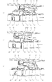
次に、ブレード21をワイピング位置から退避位置に切り換える動作について、図10を用いて説明する。図10(a)〜図10(c)において、ワイピング領域外においてワイパユニット46と対向する位置にクリーナホルダ31が設けられている。クリーナホルダ31には、記録ヘッド2をワイピングした際にブレード21に付着したインクを掻き取るためのブレードクリーナ30が保持されている。クリーナホルダ31には、リリースレバー28がバネ29の引張りによって付勢されながら回動可能に支持されている。リリースレバー28は当接部23と当接し得る位置に設けられている。
Next, the operation of switching the
図10(a)はノズル面ワイピングの際のブレード21の状態を示す。ブレードホルダ22は通常の向きであり、ブレード21はブレード面が記録ヘッド2のノズル面に対して垂直な向き(ワイピング位置)となっている。この状態においては、ブレード21の先端部は吸引口11の先端部より、記録ヘッド2のノズル面により近い位置関係となっている。ここで、図10(a)の矢印方向にワイパユニット46が移動すると、ブレード21はブレードクリーナ30と接触して、ブレード21に付着したインクやゴミがブレードクリーナ30に掻き取られる。この動作の途中で、ワイパユニット46の当接部23がリリースレバー28の斜面に当接し、リリースレバー28の斜面は当接部23に押圧されてバネ29の付勢に抗して徐々に回動する。当接部23がリリースレバー28の斜面を通り過ぎると、バネ29の付勢によってリリースレバー28は元の状態に戻る。
FIG. 10A shows the state of the
図10(b)は、ブレード21のクリーニングが終了した状態を示す。ここで、図10(b)の矢印の方向にワイパユニット46が移動すると、当接部23がリリースレバー28の端面に当接する。この方向からリリースレバー28を押しても、リリースレバー28はクリーナホルダ31の係止部によって固定されており回動しない。そのため、リリースレバー28に当接部23が押されて、ブレードホルダ22がバネ25の引張りによる付勢に抗してワイパユニット46の進行方向と反対方向に回動する。回動が終わるとバネ25の引張力が回動した状態を維持する方向の力として働く。
FIG. 10B shows a state where the cleaning of the
図10(c)は、ブレードホルダ22が回動した結果の状態を示す。ブレードホルダ22は傾いた向きであり、ブレード21はブレード面が記録ヘッド2のノズル面に対して傾いた向き(退避位置)となっている。この状態においては、ブレード21の先端部は、先のワイピング位置に較べてノズル面からより離れた位置になり、ノズル面とは非接触である。つまり、第3方向において、ワイピング位置におけるブレード先端部の位置と、退避位置におけるブレード先端部の位置の間に、吸引口11の先端部(吸引手段のノズル面に最も近い部位)があるような位置関係となっている。
FIG. 10C shows a state as a result of rotating the
ブレード21を退避位置からワイピング位置に切り換える動作について、図11を用いて説明する。ブレード21が退避位置にある図11(a)の状態において、ワイパユニット46が矢印方向へ移動する。ブレードホルダ22の当接部23は、フレーム47に固設されたトリガレバー27の先端部に当接する。さらに移動すると、トリガレバー27に押圧されてブレードホルダ22が回動して、ブレード21は、図11(b)に示すワイピング位置に移行して切り換えが完了する。
The operation of switching the
図12はクリーニング機構の動作を説明するための側面図である。図12(a)は吸引口11によって記録ヘッド2のクリーニングを行っている吸引モードの状態である。図12(b)はブレード21によって記録ヘッド2のクリーニングを行っているワイピングモードの状態である。
FIG. 12 is a side view for explaining the operation of the cleaning mechanism. FIG. 12A shows the state of the suction mode in which the
吸引モードでは、図12(a)のように、ブレード21を退避位置にする。吸引口11の先端部と記録ヘッド2のノズル面とが接触するように、記録ヘッド2の第3方向における位置を設定して保持する。負圧発生手段により吸引口11内に負圧を発生させながら、ワイパユニット46を第2方向に移動させると、ノズルに付着したインクやゴミを吸引口11から吸引し除去することができる。ワイパユニット46が第2方向に移動する最中に、記録ヘッド2からノズル面よりも突出した封止部123に吸引口11が第3方向に押される。上述したように、ワイパユニット46において吸引ホルダ12は、ノズル面に対して逃げる方向(第3方向)に変位可能となっているので、吸引口11が押されもその動きを吸引ホルダ12の変位によって逃がすことができる。なお、吸引のクリーニングの際に、吸引口11とノズル面とを接触させることは必須ではない。接触させずに極めて近い位置まで近づけた状態で負圧を与えても吸引を行なうことができる。すなわち、吸引モードにおいては、吸引口11とノズル面とは近接(当接を含む)させればよい。
In the suction mode, the
上述した図6のように、距離Lhと距離Lcが等しいので、第1吸引口11aと第2吸引口11bがそれぞれ対応するノズルチップ120の封止部123と対向するタイミングは等しくなる。その後、第1吸引口11aと第2吸引口11bが第1および第2のノズルチップ120に含まれるノズル列に対向するタイミングも等しくなる。吸引口11が封止部123の段差に乗り上げる際には、吸引口11をチルトさせる方向の力が、吸引口11を介して吸引ホルダ12に加わって傾く。また、乗り上げている最中には吸引口11は第3方向に押圧されて変位する。第1吸引口11a、第2吸引口11bが各列の封止部123に乗り上げるタイミングは略同じなので、これら2つの吸引口による吸引ホルダ12が傾くタイミングは略同じである。第1吸引口11a、第2吸引口11bが第3方向に押し込まれるタイミングもほぼ同じである。そのため、第1吸引口11aと第2吸引口11bがノズル吸引を行なっている最中に、吸引ホルダ12が傾いたり押し込まれたりして、吸引が不安定になることがない。以上の理由により、ノズルのクリーニング信頼性が向上する。
Since the distance Lh and the distance Lc are the same as in FIG. 6 described above, the timing at which the first suction port 11a and the
吸引モードでは、移動機構によりワイパユニット46が第2方向で往復移動し、往路移動時と復路移動時とで吸引口11内部に与える負圧、すなわち吸引力が異なるように負圧発生手段が制御される。具体的には、往路移動時の方が復路移動時よりも負圧が大きい。更に、吸引モードでは、ワイパユニット46が第2方向に往復移動し、往路移動時と復路移動時で移動速度が異なる。具体的には、往路移動時の方が復路移動時よりも速度が小さい。往復で吸引する際には、最初の往路で大半のインクやゴミが吸収され、次の復路では残った僅かなインクやゴミを除去するに過ぎない。従って、より多くのインクを吸収する往路において復路よりも負圧を大きくする/移動速度を小さくしてゆっくり動かすことで、最初の動作でより確実に多量の吸引が行なわれる。復路では負圧を小さくする/速度を大きくすることで、消費電力や動作音の低減/往復動作のトータル時間を短くすることができる。
In the suction mode, the
一方、ワイピングモードでは、図12(b)のように、ブレード21をワイピング位置に切り換える。ブレード21の先端部と記録ヘッド2のノズル面とが適切に接触するように、記録ヘッド2の第3方向における位置を設定して保持する。このとき、吸引口11の先端部と記録ヘッド2のノズル面とは、図12(a)の状態よりも離れる。負圧発生手段は停止する。ワイパユニット46を第2方向に移動させると、ブレード21によりノズル面をワイピングしてインクやゴミを払拭して除去することができる。
On the other hand, in the wiping mode, the
以上のように、クリーニング機構は、吸引モードとワイピングモードの2つのモードを有し、同一のワイパユニット46でいずれかのモードを選択的に実施することが可能である。例えば、ノズルのインク吐出状態を判断して、この判断結果に応じて適切なモードが選択する。具体的には、不吐出のノズルがないとの判断結果であれば、ワイピングモードを選択する。ブレード21によりノズル面およびベース基板124をワイピングしてインクやゴミを払拭して除去する。これにより、ノズルからインクを消費することなくノズル面のクリーニングを実施できる。不吐出のノズルがあるとの判断結果であれば、吸引モードを選択する。吸引口11によりノズル面およびノズルに付着したインクやゴミを吸引する。これにより、ノズルからのインク消費量を抑えつつクリーニングを実施できる。
As described above, the cleaning mechanism has two modes, that is, the suction mode and the wiping mode, and any one mode can be selectively performed by the
また、シートに連続で大量の記録を行なった場合には、ノズル面およびベース基板124に多くのインクやゴミが付着している可能性がある。このような場合には、ワイピンクモードを実行した後に吸引モードを実行する。ワイピングモードによりノズル面およびベース基板124のインクやゴミを払拭して除去し、次いで、吸引モードによりノズル面およびノズルに付着したインクやゴミを吸引する。これにより、クリーニング動作のトータル時間を短くでき、且つノズルからのインク消費量を抑えたクリーニングを実施できる。
Further, when a large amount of recording is continuously performed on the sheet, there is a possibility that a lot of ink and dust are attached to the nozzle surface and the
以上の実施形態では負圧によって吸引を行なう吸引手段であるが、これに限定されるものではない。例えば、負圧ではなくインク吸収体を用いて吸引を行なう吸引手段であってもよい。上述した図6の第1吸引口11aと第2吸引口11bと同じ位置に、第1インク吸収体と第2インク吸収体の接触部を位置させる。インク吸収体は、多孔質体等の吸水性の高い材質を用いれば、単位時間により多くのインクの吸引を行なうことができる。距離Lhと距離Lcは等しいので、第1インク吸収体と第2インク吸収体の接触部がそれぞれ対応するノズルチップ120の封止部123と対向するタイミングは等しくなる。その後、第1インク吸収体と第2インク吸収体が第1および第2のノズルチップ120に含まれるノズル列に対向するタイミングも等しくなる。そのため、吸引モードにおいてはノズルのクリーニング信頼性が向上する。
In the above embodiment, the suction means performs suction with a negative pressure, but is not limited to this. For example, a suction unit that performs suction using an ink absorber instead of a negative pressure may be used. The contact portion between the first ink absorber and the second ink absorber is positioned at the same position as the first suction port 11a and the
以上の実施形態では、2列の千鳥配列でノズルチップ120を並べた例を示したが、これ以外の規則的な配列であってもよい。いずれにせよ、記録ヘッド2は、それぞれがノズル列を有する複数の第1ノズルチップと複数の第2ノズルチップが、異なる列として第2方向に沿って並べられ、且つ隣接する前記第1ノズルチップと前記第2ノズルチップは前記第2方向でずれた位置関係とする。そして、隣接する第1ノズルチップと第2ノズルチップは、これらに含まれるノズル列の一部が、第2方向においてオーバーラップする。
In the above embodiment, an example in which the
図13はノズルチップの別の配列の例を示す。第1ノズルチップ列125、第2ノズルチップ列126、第3ノズルチップ列127の3列を有し規則的に配列されている。これに合わせて、第1吸引口11a、第2吸引口11b、第3吸引口11cの3つが対向して配されている。第2方向において、第1吸引口11aと第2吸引口11bの間の距離(ずれ量)、第2吸引口11bと第3吸引口11c間の距離、第3吸引口11cと第1吸引口11aの間の距離は、いずれもLcである。第2方向において、第1列と第2列の隣接するノズルチップの間の距離(ずれ量)、第2列と第3列の隣接するノズルチップの間の距離、第3列と第1列の隣接するノズルチップの間の距離は、いずれもLhである。図6の例と同様、LcとLhは等しい(前述したように略等しいを含む)。また、Dc<Dhを満たす。従って、第1吸引口11a、第2吸引口11b、第3吸引口11bがノズル吸引を行なっている最中に、吸引ホルダ12が傾いたり押し込まれたりして吸引が不安定になることがなく、ノズルのクリーニング信頼性が向上する。このように、複数列のうちの2つを取り出してみたとき、第1吸引手段と第2吸引手段とは、異なる列の隣接する第1ノズルチップと第2ノズルチップの第2方向でのずれに対応して、第2方向でずれた位置関係となっている。
FIG. 13 shows an example of another arrangement of nozzle tips. The first
以上の実施形態は、固定された記録ヘッド2に対してワイパユニット46が移動するもであるが本発明はこれに限定されず、ワイパユニットに対して記録ヘッドが移動してクリーニングを行なうシステムであってもよい。すなわち、本発明は、記録ヘッドのノズル列のうちの一部のノズルに対向して、ノズル列の形成方向に沿って相対的な移動がなされるインク吸引手段を有する記録装置に適用可能である。
In the above embodiment, the
2 記録ヘッド
11 吸引口
21 ブレード
23 封止部
46 ワイパユニット
120 ノズルチップ
2 Recording
Claims (8)
前記第1方向と交差する第2方向に沿って複数のノズルが配列された第1ノズルチップが前記第2方向に沿って複数設けられた第1ノズルチップ群と、前記第2方向に沿って複数のノズルが配列された第2ノズルチップが前記第2方向に沿って複数設けられた第2ノズルチップ群と、が配された基板を有し、前記第1ノズルチップ群と前記第2ノズルチップ群は前記第1方向においてずれて配置され、かつ隣接する前記第1ノズルチップと前記第2ノズルチップは前記第2方向において所定量ずれて配置され、さらに前記第1ノズルチップの前記第2方向における両端部及び前記第2ノズルチップの前記第2方向における両端部に前記基板から突出した封止部が設けられた記録ヘッドと、
を備える記録装置において、
前記第1ノズルチップからインクを吸引するための第1吸引手段と、前記第2方向において前記第1吸引手段に対して前記所定量ずれて配され前記第2ノズルチップからインクを吸引するための第2吸引手段と、を有する吸引ホルダと、
前記第1吸引手段及び前記第2吸引手段が前記基板に当接するように前記吸引ホルダを付勢する付勢部材と、を備え、
前記吸引ホルダは前記付勢部材に付勢されることによって前記第1吸引手段及び前記第2吸引手段が前記基板に当接した状態のまま前記第2方向に移動し、かつ前記第1吸引手段及び前記第2吸引手段が前記封止部を乗り越えるときの動きが前記付勢部材によって吸収されることを特徴とする記録装置。 Conveying means for conveying the sheet in the first direction;
A first nozzle chip group in which a plurality of first nozzle chips in which a plurality of nozzles are arranged along a second direction intersecting the first direction is provided along the second direction, and along the second direction And a second nozzle chip group in which a plurality of second nozzle chips in which a plurality of nozzles are arranged are provided along the second direction, and the first nozzle chip group and the second nozzle. The chip groups are displaced in the first direction, and the adjacent first nozzle chip and the second nozzle chip are displaced by a predetermined amount in the second direction, and further, the second nozzle chip has the second nozzle chip. A recording head provided with sealing portions protruding from the substrate at both ends in the direction and both ends in the second direction of the second nozzle chip;
In a recording apparatus comprising:
A first suction means for sucking ink from the first nozzle chip, and a suction means for sucking ink from the second nozzle chip arranged in the second direction and shifted by the predetermined amount with respect to the first suction means. A suction holder having a second suction means ;
A biasing member that biases the suction holder so that the first suction means and the second suction means abut against the substrate ;
The suction holder is moved to the left the second direction state where the first suction means and said second suction means is in contact with the substrate by being urged in the biasing member, and the first suction means and a recording apparatus in which the movement when said second suction means rides over the sealing portion and said Rukoto is absorbed by the urging member.
Priority Applications (5)
| Application Number | Priority Date | Filing Date | Title |
|---|---|---|---|
| JP2009262072A JP5455575B2 (en) | 2009-11-17 | 2009-11-17 | Recording device |
| EP20100014136 EP2322349B1 (en) | 2009-11-17 | 2010-10-29 | Recording apparatus |
| KR1020100110985A KR101445427B1 (en) | 2009-11-17 | 2010-11-09 | Recording apparatus |
| CN201010542592.1A CN102145582B (en) | 2009-11-17 | 2010-11-12 | Recording apparatus |
| US12/946,733 US9242470B2 (en) | 2009-11-17 | 2010-11-15 | Recording apparatus |
Applications Claiming Priority (1)
| Application Number | Priority Date | Filing Date | Title |
|---|---|---|---|
| JP2009262072A JP5455575B2 (en) | 2009-11-17 | 2009-11-17 | Recording device |
Publications (3)
| Publication Number | Publication Date |
|---|---|
| JP2011104864A JP2011104864A (en) | 2011-06-02 |
| JP2011104864A5 JP2011104864A5 (en) | 2013-04-04 |
| JP5455575B2 true JP5455575B2 (en) | 2014-03-26 |
Family
ID=43825327
Family Applications (1)
| Application Number | Title | Priority Date | Filing Date |
|---|---|---|---|
| JP2009262072A Active JP5455575B2 (en) | 2009-11-17 | 2009-11-17 | Recording device |
Country Status (5)
| Country | Link |
|---|---|
| US (1) | US9242470B2 (en) |
| EP (1) | EP2322349B1 (en) |
| JP (1) | JP5455575B2 (en) |
| KR (1) | KR101445427B1 (en) |
| CN (1) | CN102145582B (en) |
Families Citing this family (10)
| Publication number | Priority date | Publication date | Assignee | Title |
|---|---|---|---|---|
| JP5858622B2 (en) * | 2011-02-10 | 2016-02-10 | キヤノン株式会社 | Inkjet recording device |
| CN104245326A (en) * | 2012-06-26 | 2014-12-24 | 惠普发展公司,有限责任合伙企业 | Print bar and print bar shroud |
| JP6429635B2 (en) * | 2015-01-16 | 2018-11-28 | キヤノン株式会社 | Inkjet recording device |
| JP6873616B2 (en) | 2016-06-29 | 2021-05-19 | キヤノン株式会社 | Inkjet recording device and its cleaning method |
| JP6824075B2 (en) * | 2017-03-13 | 2021-02-03 | キヤノン株式会社 | Recording device |
| JP6995514B2 (en) | 2017-07-07 | 2022-01-14 | キヤノン株式会社 | Inkjet recording device |
| DE102018107063A1 (en) * | 2018-03-26 | 2019-09-26 | Océ Holding B.V. | Method and cleaning unit for cleaning a printing bar of a printing system and a corresponding printing system |
| JP7379037B2 (en) * | 2018-10-04 | 2023-11-14 | キヤノン株式会社 | Inkjet recording method and inkjet recording device |
| JP7224836B2 (en) | 2018-10-05 | 2023-02-20 | キヤノン株式会社 | Recording device and recovery method |
| JP7290432B2 (en) * | 2019-03-04 | 2023-06-13 | ローランドディー.ジー.株式会社 | inkjet printer |
Family Cites Families (23)
| Publication number | Priority date | Publication date | Assignee | Title |
|---|---|---|---|---|
| JP3161050B2 (en) * | 1991-06-12 | 2001-04-25 | 富士ゼロックス株式会社 | Inkjet head maintenance device |
| JPH06270420A (en) * | 1993-03-19 | 1994-09-27 | Fuji Xerox Co Ltd | Maintenance device of ink jet recording apparatus |
| JPH06320744A (en) * | 1993-04-19 | 1994-11-22 | Xerox Corp | Wet wiping maintenance device for full-width ink jet printer |
| US5500660A (en) * | 1993-06-24 | 1996-03-19 | Hewlett-Packard Company | Wiper for inkjet printhead nozzle member |
| JP3177128B2 (en) * | 1994-08-10 | 2001-06-18 | キヤノン株式会社 | Discharge unit, ink jet cartridge using discharge unit, ink jet printing apparatus and method |
| US5635965A (en) * | 1995-01-31 | 1997-06-03 | Hewlett-Packard Company | Wet capping system for inkjet printheads |
| JPH1044419A (en) * | 1996-07-31 | 1998-02-17 | Canon Inc | Liquid jet head, manufacture thereof, liquid jet unit, and recorder |
| JPH10181040A (en) * | 1996-12-27 | 1998-07-07 | Canon Inc | Recorder and method for recovering recording head |
| US6347858B1 (en) * | 1998-11-18 | 2002-02-19 | Eastman Kodak Company | Ink jet printer with cleaning mechanism and method of assembling same |
| JP2001260392A (en) * | 2000-03-14 | 2001-09-25 | Toshiba Tec Corp | Ink jet head, and its cleaning apparatus |
| JP4711280B2 (en) * | 2003-10-14 | 2011-06-29 | オリンパス株式会社 | Image recording device |
| US7300135B2 (en) * | 2004-02-27 | 2007-11-27 | Brother Kogyo Kabushiki Kaisha | Ink jet recording apparatus and maintenance mechanism therefor |
| JP4645138B2 (en) * | 2004-09-30 | 2011-03-09 | コニカミノルタホールディングス株式会社 | Inkjet recording device |
| KR100782816B1 (en) * | 2005-08-19 | 2007-12-06 | 삼성전자주식회사 | Inkjet image forming apparatus and mainmtenance method thereof |
| CN100404263C (en) * | 2005-10-14 | 2008-07-23 | 研能科技股份有限公司 | Device for cleaning ink-jet head |
| JP4735193B2 (en) * | 2005-10-31 | 2011-07-27 | ブラザー工業株式会社 | Inkjet recording device |
| JP4914627B2 (en) * | 2006-03-22 | 2012-04-11 | 富士フイルム株式会社 | Discharge recovery device for liquid discharge head and image forming apparatus having the same |
| JP4942494B2 (en) * | 2007-01-24 | 2012-05-30 | 株式会社リコー | Image forming apparatus |
| JP2008246728A (en) * | 2007-03-29 | 2008-10-16 | Fujifilm Corp | Maintenance device of inkjet head, inkjet head assembly, inkjet recorder equipped with this and maintenance method of inkjet head |
| JP4386092B2 (en) * | 2007-04-06 | 2009-12-16 | セイコーエプソン株式会社 | Fluid ejecting apparatus and method for controlling the apparatus |
| KR20080099498A (en) * | 2007-05-09 | 2008-11-13 | 삼성전자주식회사 | Inkjet image-forming apparatus |
| US20090179954A1 (en) * | 2008-01-16 | 2009-07-16 | Silverbrook Research Pty Ltd | Printhead nozzle face wiper blade with multiple, inclined contact sections |
| US7984549B2 (en) * | 2008-09-11 | 2011-07-26 | Canon Kabushiki Kaisha | Method of manufacturing ink-jet recording head |
-
2009
- 2009-11-17 JP JP2009262072A patent/JP5455575B2/en active Active
-
2010
- 2010-10-29 EP EP20100014136 patent/EP2322349B1/en active Active
- 2010-11-09 KR KR1020100110985A patent/KR101445427B1/en active IP Right Grant
- 2010-11-12 CN CN201010542592.1A patent/CN102145582B/en not_active Expired - Fee Related
- 2010-11-15 US US12/946,733 patent/US9242470B2/en active Active
Also Published As
| Publication number | Publication date |
|---|---|
| CN102145582B (en) | 2014-04-16 |
| US20110115846A1 (en) | 2011-05-19 |
| EP2322349A2 (en) | 2011-05-18 |
| EP2322349B1 (en) | 2013-10-23 |
| JP2011104864A (en) | 2011-06-02 |
| CN102145582A (en) | 2011-08-10 |
| EP2322349A3 (en) | 2012-09-19 |
| KR101445427B1 (en) | 2014-09-26 |
| US9242470B2 (en) | 2016-01-26 |
| KR20110055398A (en) | 2011-05-25 |
Similar Documents
| Publication | Publication Date | Title |
|---|---|---|
| JP5455575B2 (en) | Recording device | |
| JP5665366B2 (en) | Recording device | |
| JP5858622B2 (en) | Inkjet recording device | |
| JP4508131B2 (en) | Inkjet printer | |
| JP4752533B2 (en) | Liquid ejecting apparatus and liquid ejecting head maintenance method | |
| JP4197004B2 (en) | Inkjet recording device | |
| JP5955053B2 (en) | Recording apparatus and recording apparatus control method | |
| US20050264601A1 (en) | Inkjet printer | |
| JP2007050704A (en) | Ink-jet image forming device and maintenance method for nozzle part | |
| JP5538826B2 (en) | Recording device | |
| JP4591014B2 (en) | Inkjet recording apparatus and multi-head unit wiping method | |
| US20090135226A1 (en) | Ink jet print head and ink jet printing apparatus | |
| JP4561108B2 (en) | Inkjet recording device | |
| JP2009269327A (en) | Inkjet recorder | |
| JP2009160786A (en) | Droplet ejector | |
| JP2010012739A (en) | Liquid ejection recording apparatus and inkjet recording apparatus | |
| JP6575501B2 (en) | Inkjet recording device | |
| JP6370213B2 (en) | Printing apparatus and printing apparatus cleaning method | |
| JP5262399B2 (en) | Inkjet recording device | |
| JP2005007711A (en) | Image recording device | |
| JP2010111008A (en) | Inkjet printer and inkjet printing method | |
| JP6429635B2 (en) | Inkjet recording device | |
| JP2007105909A (en) | Recovery mechanism of inkjet printer | |
| JP2009132009A (en) | Recorder |
Legal Events
| Date | Code | Title | Description |
|---|---|---|---|
| A621 | Written request for application examination |
Free format text: JAPANESE INTERMEDIATE CODE: A621 Effective date: 20121107 |
|
| A521 | Written amendment |
Free format text: JAPANESE INTERMEDIATE CODE: A523 Effective date: 20130215 |
|
| A871 | Explanation of circumstances concerning accelerated examination |
Free format text: JAPANESE INTERMEDIATE CODE: A871 Effective date: 20130215 |
|
| A975 | Report on accelerated examination |
Free format text: JAPANESE INTERMEDIATE CODE: A971005 Effective date: 20130221 |
|
| A131 | Notification of reasons for refusal |
Free format text: JAPANESE INTERMEDIATE CODE: A131 Effective date: 20130305 |
|
| A521 | Written amendment |
Free format text: JAPANESE INTERMEDIATE CODE: A523 Effective date: 20130507 |
|
| A131 | Notification of reasons for refusal |
Free format text: JAPANESE INTERMEDIATE CODE: A131 Effective date: 20130625 |
|
| A521 | Written amendment |
Free format text: JAPANESE INTERMEDIATE CODE: A523 Effective date: 20130826 |
|
| A131 | Notification of reasons for refusal |
Free format text: JAPANESE INTERMEDIATE CODE: A131 Effective date: 20130917 |
|
| A521 | Written amendment |
Free format text: JAPANESE INTERMEDIATE CODE: A523 Effective date: 20131118 |
|
| TRDD | Decision of grant or rejection written | ||
| A01 | Written decision to grant a patent or to grant a registration (utility model) |
Free format text: JAPANESE INTERMEDIATE CODE: A01 Effective date: 20131210 |
|
| A61 | First payment of annual fees (during grant procedure) |
Free format text: JAPANESE INTERMEDIATE CODE: A61 Effective date: 20140107 |
|
| R151 | Written notification of patent or utility model registration |
Ref document number: 5455575 Country of ref document: JP Free format text: JAPANESE INTERMEDIATE CODE: R151 |