JP5455246B2 - Private branch exchange system - Google Patents
Private branch exchange system Download PDFInfo
- Publication number
- JP5455246B2 JP5455246B2 JP2011063900A JP2011063900A JP5455246B2 JP 5455246 B2 JP5455246 B2 JP 5455246B2 JP 2011063900 A JP2011063900 A JP 2011063900A JP 2011063900 A JP2011063900 A JP 2011063900A JP 5455246 B2 JP5455246 B2 JP 5455246B2
- Authority
- JP
- Japan
- Prior art keywords
- private branch
- branch exchange
- hotel
- information
- room
- Prior art date
- Legal status (The legal status is an assumption and is not a legal conclusion. Google has not performed a legal analysis and makes no representation as to the accuracy of the status listed.)
- Expired - Fee Related
Links
Images


Description
本発明は、構内交換システムに関し、特に、1台の構内交換機に対して複数のホストコンピュータを接続するシステムに関する。 The present invention relates to a private branch exchange system, and more particularly to a system for connecting a plurality of host computers to one private branch exchange.
従来、ホテルや旅館等の客室を提供する施設には、規模の大小に関わらず、施設内に構内交換機を設置し、施設の予約業務等で使用するホストコンピュータをこの構内交換機と接続することにより、客室の電話システム管理や中継台等によるCRM(Customer Relationship Management:顧客関係管理)を提供している。 Conventionally, facilities that provide guest rooms such as hotels and inns, regardless of the size, install a private branch exchange in the facility and connect a host computer used for facility reservations etc. to this private branch exchange. In addition, it provides CRM (Customer Relationship Management) by the telephone system management of the guest rooms and the attendant console.
このような構内交換機とホストコンピュータとの接続方式としては、例えば、構内交換機とホストコンピュータとを1対1で接続する方式(例えば、特許文献1)や、複数対複数で接続する方式(例えば、特許文献2)が一般的に用いられている。 As a connection method between such a private branch exchange and a host computer, for example, a method of connecting a private branch exchange and a host computer in a one-to-one relationship (for example, Patent Document 1), or a method of connecting in a plural-to-multiple manner (for example, Patent document 2) is generally used.
例えば、図7に示すように、引用文献1に記載の構内交換システム100は、CPU(Central Processing Unit)110を有するPBX(Private Branch eXchange:構内交換機)101と、ホストコンピュータ102と、客室内の電話機104A及び104Bを収容接続する端末接続装置103とで構成される。
For example, as shown in FIG. 7, the private
PBX101は、通信路111a、端末制御情報路111b及び特殊データ伝送路111cからなるコンピュータ回線111により、ホストコンピュータ102と接続される。また、PBX101は、通信路112a及び制御情報路112bからなる端末回線112により、端末接続装置103と接続される。
The PBX 101 is connected to the
構内交換システム100では、ホストコンピュータ102が端末からデータを受信する場合、PBX101は、端末回線112を介して受信した端末からのデータを、CPU110で記憶する。そして、ホストコンピュータ102は、コンピュータ回線111を介してPBX101のCPU110から発呼端末の番号を受信して情報を処理する。
In the private
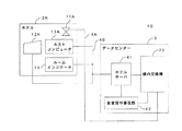
また、例えば、図8に示すように、引用文献2に記載の構内交換システム120は、ネットワークコントロールノード(NCN)121A、ローカルネットワークノード(LN)121B及び121Cからなる3つのノードと、各々のノード121A〜121Cに接続されるホストコンピュータ122A、122B及び122Cと、すべてのノード121A〜121Cに対してインターネット回線130を介して接続されるサーバ123と、各々のノード121A〜121Cに接続される客室内の電話機124A及び124Bと、ネットワークコントロールノード121Aに接続される中継台125とから構成される。
Further, for example, as shown in FIG. 8, the private
ネットワークコントロールノード121A、ローカルネットワークノード121B及び121Cは、各々、通信路スイッチ(TDSW)131A、131B及び131Cと、通信制御部132A、132B及び132Cとを備える。また、ネットワークコントロールノード121A、ローカルネットワークノード121B及び121Cにおける各種サービス機能制御に必要な情報は、図示しない局データ記憶メモリに保持されており、各ノードに固有な情報としてローカル局データ(LDM)133A、133B及び133Cと、各ノードに共通なネットワーク局データ(NDM)134A、134B及び134Cを有する。
Each of the
サーバ123は、客室に対応するノードのホストコンピュータ122A〜122Cを導き出すデータベース141と、各種情報を各ノード121A〜121Cのホストコンピュータ122A〜122Cに転送するイベント転送回路142を備える。
The server 123 includes a
構内交換システム120において、ネットワークコントロールノード121Aは、異なる客室各々の客室情報を別のノードのホストコンピュータに処理させる際に、検出された客室情報によって、インターネット回線130で接続されたデータベース141に対して処理ノードの検索を行う。ネットワークコントロールノード121Aは、検索された処理ノードのホストコンピュータ122A〜122Cに対して、イベント転送回路142から客室情報を転送して処理させる。
In the private
しかしながら、引用文献1に記載の構内交換システムでは、構内交換機とホストコンピュータとを1対1で接続することのみが考慮され、また、引用文献2に記載の構内交換システムでは、構内交換機とホストコンピュータとを複数対複数で接続することのみが考慮されている。そのため、1台の構内交換機を複数のホストコンピュータと接続することができないという問題があった。
However, in the private branch exchange system described in the cited
これは、従来の構内交換システムにおいて、通常、構内交換機を使用する際に、自施設内のみ通話可能となるセキュリティが実施されているためである。このようなセキュリティは、各施設毎に異なるシステムが適用されており、例えば、1台の構内交換機を複数の施設で共有して使用する場合には、従来の技術を用いて同様のセキュリティを実施することが困難である。 This is because, in a conventional private branch exchange system, normally, when using a private branch exchange, security is implemented so that calls can be made only within the own facility. For such security, different systems are applied to each facility. For example, when one private branch exchange is shared by multiple facilities, the same security is implemented using conventional technology. Difficult to do.
また、従来は、施設毎に独自の通信フォーマットを適用したホストコンピュータを使用しているため、1台の構内交換機では、複数のホストコンピュータに対応することができない。 Conventionally, since a host computer to which a unique communication format is applied for each facility is used, a single private branch exchange cannot handle a plurality of host computers.
さらに、従来の構内交換システムでは、1台の構内交換機と複数のホストコンピュータとを接続した場合に、ホストコンピュータから受信した客室情報を各々の施設毎に表示制御することができない。例えば、1台の構内交換機を複数のホテルで使用した場合に客室情報を検索すると、他のホテルの客室情報が検索結果として表示される虞がある。これは、1台の構内交換機において管理できる客室情報が、1つのホテルのみに固定されているためである。 Further, in the conventional private branch exchange system, when one private branch exchange is connected to a plurality of host computers, the room information received from the host computer cannot be displayed and controlled for each facility. For example, when room information is searched when one private branch exchange is used at a plurality of hotels, room information of other hotels may be displayed as a search result. This is because room information that can be managed by one private branch exchange is fixed to only one hotel.
また、従来の構内交換システムでは、構内交換機とホストコンピュータとが1対1で対応しているため、各施設内に構内交換機を設置する必要があるが、施設毎に構内交換機を設置すると、施設内の一定のスペースを占有してしまうことになる。これにより、施設内のスペースを有効に利用できず、コストが増大するという問題があった。 In addition, in the conventional private branch exchange system, there is a one-to-one correspondence between the private branch exchange and the host computer, so it is necessary to install a private branch exchange in each facility. However, if a private branch exchange is installed in each facility, Will occupy a certain space inside. As a result, there is a problem in that the space in the facility cannot be used effectively and the cost increases.
そこで、本発明は、上記従来の技術における問題点に鑑みてなされたものであって、1台の構内交換機と複数のホストコンピュータとを接続した場合でも、既存のサービスやセキュリティを提供することが可能な構内交換システムを提供することを目的とする。 Accordingly, the present invention has been made in view of the problems in the above-described conventional technology, and can provide existing services and security even when one private branch exchange is connected to a plurality of host computers. The aim is to provide a possible private branch exchange system.
また、本発明は、ホテル内に設置される構内交換機による占有スペースを削減し、コストを削減することが可能な構内交換システムを提供することを目的とする。 Another object of the present invention is to provide a private branch exchange system capable of reducing the space occupied by a private branch exchange installed in a hotel and reducing the cost.
上記目的を達成するため、本発明は、構内交換システムであって、客室利用者に関する客室情報の処理を行うホストコンピュータと、客室毎に設けられ、外部又は他の客室との通話を行う電話機と、前記客室の在室状態を表示するルームインジケータとが1つ又は複数の施設の各々に設置され、前記ホストコンピュータと接続され、該ホストコンピュータとの間での前記客室情報の送受信及び該客室情報の管理を行うサーバと、前記電話機及び前記サーバに接続され、電話交換処理を行う構内交換機と、前記サーバ及び前記構内交換機に接続され、メッセージを記憶する留守番電話機とが前記1つ又は複数の施設とは異なる他の施設に設置され、前記サーバは、前記1つ又は複数の施設の各々を識別する施設識別情報及び前記1つ又は複数の施設の電話機に対する内線番号の番号帯を割り当てると共に、前記客室情報を管理する制御部と、前記施設識別情報及び前記番号帯を関連付けて記憶するデータベースとを有し、前記制御部は、前記施設識別情報と前記ホストコンピュータから送信された前記客室情報とを関連付けて前記データベースに登録し、前記構内交換機は、同一の番号帯間での通話のみが可能となるように設定し、前記ルームインジケータは、前記客室の在室状態を示す客室在室情報を前記サーバに送信し、前記サーバは、前記制御部により、受信した前記客室在室情報を前記ルームインジケータが設置された施設に対して割り当てられた前記施設識別情報と関連付けて前記データベースに登録すると共に、前記客室在室情報を前記構内交換機に送信し、前記構内交換機は、受信した前記客室在室情報が前記客室の不在を示す場合に、前記不在状態の客室に設置された電話機に対する着信を前記留守番電話機に転送するように設定し、前記サーバは、前記制御部により、前記留守番電話機にメッセージが記憶された場合に、該メッセージが記憶されたことを示す情報を、前記施設識別情報に関連付けられた前記客室情報に追加して登録することを特徴とする。 In order to achieve the above object, the present invention provides a private branch exchange system, a host computer for processing room information relating to a guest of a guest room, and a telephone provided for each guest room for making a call with an external or other guest room. A room indicator that displays the occupancy status of the guest room is installed in each of one or a plurality of facilities, connected to the host computer, and transmission / reception of the guest room information to / from the host computer and the guest room information The one or more facilities comprising: a server for managing the telephone; a private branch exchange connected to the telephone and the server for performing telephone exchange processing; and an answering machine connected to the server and the private branch exchange for storing messages Installed in another facility different from the server, the server includes facility identification information for identifying each of the one or more facilities and the one or more facilities. And assigning an extension number number band to the telephone set, and managing the guest room information, and a database storing the facility identification information and the number band in association with each other, wherein the control unit includes the facility identification Information and the room information transmitted from the host computer are associated with each other and registered in the database, the private branch exchange is set so that only a call between the same number bands is possible, and the room indicator is The room occupancy information indicating the occupancy status of the guest room is transmitted to the server, and the server is assigned the received room occupancy information to the facility where the room indicator is installed by the control unit. In addition to registering in the database in association with the facility identification information, transmitting the cabin occupancy information to the private branch exchange, And the server sets the incoming call to the telephone set in the absent guest room to be forwarded to the answering machine when the received guest room presence information indicates the absence of the guest room, When the message is stored in the answering machine, the information indicating that the message is stored is added to the room information associated with the facility identification information and registered .
そして、本発明によれば、各施設に対して施設識別情報を割り当て、この施設識別情報に基づき各施設におけるサービスやセキュリティを制御するため、1台の構内交換機と複数のホストコンピュータとを接続した場合でも、従来と同様のサービスやセキュリティを提供することができる。 According to the present invention, facility identification information is assigned to each facility, and one private branch exchange and a plurality of host computers are connected to control services and security in each facility based on the facility identification information. Even in this case, it is possible to provide services and security similar to those in the past.
また、本発明によれば、ホストコンピュータを各施設毎に設置し、構内交換機をこれらの施設とは異なる他の施設に設置するため、従来、各施設に設置していた構内交換機による占有スペースを削減することができる。 In addition, according to the present invention, since the host computer is installed in each facility and the private branch exchange is installed in another facility different from these facilities, the space occupied by the private branch exchange that has conventionally been installed in each facility is reduced. Can be reduced.
さらに、本発明によれば、客室在室情報が客室の不在を示す場合に、不在状態の客室に設置された電話機に対する着信を留守番電話機に転送するように設定し、留守番電話機にメッセージが記憶された場合に、メッセージが記憶されたことを示す情報を、施設識別情報に関連付けられた客室情報に追加して登録するため、1台の構内交換機と複数のホストコンピュータとを接続した場合でも、従来と同様に、客室の在室状態を適切に表示することができると共に、不在時に着信があった場合に、メッセージを記憶することができ、また、中継台を使用して客室情報を検索した際に、記憶されたメッセージの有無を確認することができる。 Furthermore, according to the present invention, when the room occupancy information indicates the absence of the guest room, the incoming call to the telephone set in the absent guest room is set to be transferred to the answering machine, and a message is stored in the answering machine. Information indicating that the message has been stored in addition to the room information associated with the facility identification information, even if one private branch exchange and a plurality of host computers are connected, In the same way as above, it is possible to properly display the occupancy status of the guest room, to store a message when there is an incoming call when there is no call, and to search for room information using the attendant console In addition, the presence or absence of the stored message can be confirmed.
上記構内交換システムにおいて、前記電話機に対する操作によりモーニングコールが設定された場合に、前記構内交換機は、前記電話機に対する操作に基づくモーニングコールを設定すると共に、前記モーニングコールが設定されたことを示す設定情報を前記サーバに送信し、前記サーバは、前記制御部により、受信した前記設定情報を前記モーニングコールが設定された電話機が設置された施設に対して割り当てられた前記施設識別情報と関連付けて前記データベースに登録し、前記設定情報を、対応する施設識別情報が割り当てられた施設の前記ホストコンピュータに送信することができる。これにより、客室情報を検索した場合に、モーニングコールが設定されたか否かを検索結果として確認することができる。 In the private branch exchange system, when a wake-up call is set by an operation on the telephone, the private branch exchange sets a wake-up call based on the operation on the telephone and setting information indicating that the wake-up call is set The server associates the received setting information with the facility identification information assigned to the facility where the telephone set with the wake-up call is installed by the control unit. And the setting information can be transmitted to the host computer of the facility to which the corresponding facility identification information is assigned. Thereby, when the guest room information is searched, it can be confirmed as a search result whether or not the wake-up call is set.
上記構内交換システムにおいて、前記構内交換機は、前記モーニングコールを実行した場合に、前記モーニングコールの実行結果を示す実行情報を前記サーバに送信し、前記サーバは、前記制御部により、受信した前記実行情報を前記モーニングコールが実行された電話機が設置された施設に対して割り当てられた前記施設識別情報と関連付けて前記データベースに登録し、前記実行情報を、対応する施設識別情報が割り当てられた施設の前記ホストコンピュータに送信することができる。これにより、客室情報を検索した場合に、モーニングコールに対する実行結果を検索結果として確認することができる。 In the private branch exchange system, when the private branch exchange executes the wake-up call, the private branch exchange transmits execution information indicating an execution result of the wake-up call to the server, and the server receives the execution received by the control unit. The information is registered in the database in association with the facility identification information assigned to the facility where the telephone on which the wake-up call is executed is installed, and the execution information is registered for the facility to which the corresponding facility identification information is assigned. It can be sent to the host computer. Thereby, when the guest room information is searched, the execution result for the wake-up call can be confirmed as the search result.
上記構内交換システムにおいて、前記他の施設に、複数の構内交換機が設置され、前記制御部は、前記複数の構内交換機を識別するための交換機識別情報を割り当てると共に、前記複数の構内交換機のうち、前記1つ又は複数の施設の各々に対応する構内交換機を決定し、前記施設識別情報と、対応付けられた構内交換機に割り当てられた前記交換機識別情報とを関連付けて前記データベースに登録することができる。これにより、複数の構内交換機を使用した場合でも、構内交換機をホテル等の施設内に設置する必要がないため、構内交換機による占有スペースを削減することができる。 In the private branch exchange system, a plurality of private branch exchanges are installed in the other facility, and the control unit assigns exchange identification information for identifying the plurality of private branch exchanges, and among the plurality of private branch exchanges, A private branch exchange corresponding to each of the one or more facilities can be determined, and the facility identification information and the exchange identification information assigned to the associated private branch exchange can be associated and registered in the database. . Thereby, even when a plurality of private branch exchanges are used, it is not necessary to install the private branch exchange in a facility such as a hotel, so that the space occupied by the private branch exchange can be reduced.
以上のように、本発明によれば、1台の構内交換機と複数のホストコンピュータとを接続した場合でも、既存のサービスやセキュリティを提供することが可能になる。 As described above, according to the present invention, existing services and security can be provided even when one private branch exchange is connected to a plurality of host computers.
また、本発明によれば、ホテル内に設置される構内交換機による占有スペースを削減し、コストを削減することが可能になる。 Further, according to the present invention, it is possible to reduce the occupied space by the private branch exchange installed in the hotel and reduce the cost.
次に、本発明を実施するための形態について、図面を参照しながら詳細に説明する。ここでは、本発明にかかる構内交換システムをホテルに適用した場合を例にとって説明する。 Next, an embodiment for carrying out the present invention will be described in detail with reference to the drawings. Here, a case where the private branch exchange system according to the present invention is applied to a hotel will be described as an example.
図1は、本発明にかかる構内交換システムの第1の実施形態を示し、この構内交換システム1では、複数のホテル2A、2B及び2Cと、これらのホテルとは別の施設であるデータセンター3とがインターネット回線4A及び4Bで接続される。
FIG. 1 shows a first embodiment of a private branch exchange system according to the present invention. In this private
ホテル2A、2B及び2Cには、各々、客室毎に設置され、外部との通話(外線発信)や同一ホテル内の異なる電話機への通話(内線発信)を行う電話機11A、11A、・・・、11B、11B、・・・及び11C、11C、・・・と、中継台12A、12B及び12Cと、フロント等に設置され、客室利用者のチェックインやチェックアウト時に、客室利用者に関する情報等の処理を行うホストコンピュータ13A、13B及び13Cとが設置される。
In the
データセンター3には、ホテルサーバ21及び構内交換機22が設置される。また、電話機11A、11B及び11Cと、構内交換機22とがインターネット回線4Aで接続され、中継台12A、12B及び12Cと、ホストコンピュータ13A、13B及び13Cと、ホテルサーバ21とがインターネット回線4Bで接続される。
In the
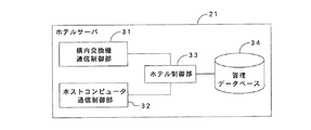
ホテルサーバ21は、図2に示すように、構内交換機22との通信を制御する構内交換機通信制御部31と、各ホテルに設置されたホストコンピュータ13A、13B及び13Cとの通信を制御するホストコンピュータ通信制御部32と、構内交換機通信制御部31及びホストコンピュータ通信制御部32による通信でやりとりされる各種情報の管理を制御するホテル制御部33と、管理データベース34とで構成される。
As shown in FIG. 2, the
管理データベース34には、ホテル毎に割り当てられ、各ホテルを識別するための識別情報であるホテルID(IDentification)と、ホテル毎に使用する内線番号の番号帯やホテル内の客室情報等とが互いに関連付けられて登録される。ホテルIDに関連付けられる客室情報は、例えば、客室番号や客室利用者の氏名、国籍等の客室利用者に関する情報である。
In the
構内交換機22は、発信元の電話回線と、発信先の電話回線とを互いに接続する電話交換処理を行うための機器である。構内交換機22は、ホテルサーバ21からの通知に基づき、同一番号帯による通話のみが可能となるように設定され、発信元及び発信先の内線番号に基づき、2つの内線番号が同一の番号帯に属するか否かを判断する。そして、2つの内線番号が同一番号帯である場合に、互いの電話回線を接続する。
The
また、構内交換機22は、各ホテルに設置された電話機の機能を制限することができる。例えば、利用されていない客室に設置された電話機からの発信機能を制限し、外線発信等を行うことができないようにすることができる。
Moreover, the
次に、上記構成を有する構内交換システム1の動作について説明する。通常時には、この構内交換システム1が導入されている各ホテルに対して、ホテルサーバ21のホテル制御部33によりホテルID及び番号帯が予め割り当てられ、ホテルIDと番号帯とが関連付けられて管理データベース34に登録されると共に、同一番号帯による通話のみが可能となるように、構内交換機22が設定された状態となっている。
Next, the operation of the private
このような状態では、同一番号帯間における通話のみが可能となり、異なる番号帯間における通話が不可となる。具体的には、例えば、ホテル2Aの電話機11A間、ホテル2Bの電話機11B間、及びホテル2Cの電話機11C間における通話が可能となり、電話機11A及び電話機11B間、電話機11B及び電話機11C間、及び電話機11A及び電話機11C間における通話が不可となる。
In such a state, only a call between the same number bands is possible, and a call between different number bands is impossible. Specifically, for example, a telephone call can be made between the telephone 11A of the hotel 2A, between the
例えば、ホテル2Aの所定の客室(例えば、「客室#1」とする)に設置された電話機11Aと、ホテル2Aの別の客室(例えば、「客室#2」とする)に設置された電話機11Aとの間で通話を行う場合、構内交換機22は、発信元の客室#1の電話機11Aの内線番号と、発信先の客室#2の電話機11Aの内線番号とに基づき、各々の内線番号が属する番号帯が同一であると判断し、客室#1及び#2の電話機11Aの電話回線を接続する。
For example, a telephone 11A installed in a predetermined guest room of the hotel 2A (for example, “
ここで、構内交換システム1に対して別のホテルを新規に追加する場合について説明する。ここでは、説明を容易とするため、構内交換システム1に対してホテル2Aを新規に追加する場合を例にとって説明する。
Here, a case where another hotel is newly added to the private
ホテル2Aに設置されたホストコンピュータ13Aからホテルサーバ21に対して接続要求が送信されると、ホテルサーバ21のホストコンピュータ通信制御部32とホストコンピュータ13Aとがインターネット回線4Bを介して接続される。ホストコンピュータ13Aからの接続要求は、ホテルサーバ21のホストコンピュータ通信制御部32で受信され、ホストコンピュータ通信制御部32は、受信した接続要求をホテル制御部33に供給する。
When a connection request is transmitted from the
ホテル制御部33は、ホストコンピュータ13Aからの接続要求を受け取ると、ホストコンピュータ13Aに対してホテルIDを割り当てると共に、ホテル2Aで使用される番号帯を決定し、ホテル2Aに対して割り当てたホテルID及び番号帯を互いに関連付けて管理データベース34に登録する。
Upon receiving a connection request from the
次に、構内交換機通信制御部31と構内交換機22とが接続され、ホテル制御部33は、ホテル2Aに対して割り当てた番号帯間における通話を可能とすると共に、この番号帯と別のホテルに対して割り当てた番号帯との間における通話を不可とするよう、構内交換機22に対して通知する。
Next, the private branch exchange
構内交換機22は、ホテルサーバ21から受信した通知に基づき、接続回線を設定する。これにより、ホテル2Aの電話機11A及びホテル2Bの電話機11B間における通話、電話機11B及びホテル2Cの電話機11C間における通話、及び電話機11A及び電話機11C間における通話が不可となると共に、各ホテル内の電話機同士での通話が可能となる。
The
次に、客室利用者がチェックイン及びチェックアウトした場合の動作について説明する。ここでは、ホテル2Aの客室利用者がチェックインした場合を例にとって説明する。 Next, an operation when a guest room user checks in and checks out will be described. Here, a case where a guest room user of the hotel 2A checks in will be described as an example.
ホテル2Aの客室利用者がチェックインし、フロントのホストコンピュータ13Aに客室情報が入力されると、ホストコンピュータ13Aは、ホテルIDと客室情報を示すチェックインテキストとをインターネット回線4Bを介してホテルサーバ21へ送信する。
When a guest room user of the hotel 2A checks in and guest room information is input to the
ホストコンピュータ13Aから送信されたホテルID及びチェックインテキストは、ホテルサーバ21のホストコンピュータ通信制御部32で受信され、ホストコンピュータ通信制御部32は、受信したホテルID及びチェックインテキストをホテル制御部33に供給する。
The hotel ID and check-in text transmitted from the
ホテル制御部33は、ホストコンピュータ通信制御部32を介して受け取ったチェックインテキストの内容を分析する。これにより、ホテル制御部33は、客室番号や客室利用者の氏名、国籍等の客室情報を得る。そして、受け取ったホテルIDと管理データベース34に登録されたホテルIDとを照合し、分析によって得られた客室情報を、対応するホテルIDと関連付けて管理データベース34に登録する。
The
また、ホテル制御部33は、ホストコンピュータ13Aからチェックインテキストを受信したこと、すなわち、ホテル2Aの客室利用者がチェックインしたことを示すチェックイン情報を、構内交換機通信制御部31を介して構内交換機22に送信する。構内交換機22は、ホテルサーバ21から受信したチェックイン情報に基づき、例えば、対象の客室に設置された電話機11Aの機能の制限を解除し、外線発信等の機能が使用可能となるように設定する。
Further, the
ホテル2Aの客室利用者がチェックアウトした場合、ホストコンピュータ13Aは、ホテルID及びチェックアウトを示すチェックアウト情報をホテルサーバ21へ送信する。ホテル制御部33は、ホストコンピュータ通信制御部32を介してホテルID及びチェックアウト情報を受け取ると、対応するホテルIDに関連付けられた客室情報を管理データベース34から削除する。また、ホテル制御部33は、ホテル2Aの客室利用者に対するチェックアウト情報を、構内交換機通信制御部31を介して構内交換機22に送信する。
When the guest room user of the hotel 2A checks out, the
構内交換機22は、ホテルサーバ21から受信したチェックアウト情報に基づき、例えば、対象の客室に設置された電話機11Aの機能を制限し、外線発信等の機能が使用不可となるように設定する。
Based on the check-out information received from the
ここで、管理データベース34には、客室情報及び番号帯がホテルIDに関連付けられて登録されることになる。この管理データベース34に登録された客室情報は、例えば、中継台からの客室情報検索の際に用いられる。例えば、ホテル2Aに設置された中継台12Aから客室情報検索が行われた場合、ホテル制御部33は、検索を行った中継台12AのホテルIDに基づき、対応するホテルIDに関連付けられた客室情報を管理データベース34から読み出し、中継台12Aに対して送信する。
Here, the guest room information and the number band are registered in the
このように、本実施の形態では、客室情報をホテルIDで管理するため、客室情報検索の際に、検索結果として異なるホテルの客室情報を読み出すことなく、適切な客室情報を得ることができる。 Thus, in this Embodiment, since room information is managed by hotel ID, appropriate room information can be obtained without reading out room information of different hotels as a search result when searching for room information.
次に、モーニングコールを実行する場合の動作について説明する。ここでは、ホテル2Bの客室利用者がモーニングコールを実行する場合を例にとって説明する。
Next, the operation when executing a wake-up call will be described. Here, a case where a guest room user of the
ホテル2Bの客室利用者が電話機11Bを操作してモーニングコールを設定すると、操作に応じたモーニングコールの設定を示す情報がインターネット回線4Aを介して構内交換機22に送信される。構内交換機22は、受信した情報に基づき、電話機11Bに対するモーニングコールを設定する。また、構内交換機22は、電話機11Bに対するモーニングコールを設定したことを示すモーニングコール設定情報をホテルサーバ21に対して送信する。
When a guest room user of the
ホテル制御部33は、構内交換機通信制御部31を介してモーニングコール設定情報を受信し、管理データベース34の対応するホテルIDに関連付けられた客室情報にモーニングコール設定情報を追加する。これにより、ホテル2Bの中継台12Bを使用して客室情報を検索した際に、各客室利用者がモーニングコールを設定したか否かを確認することができる。
The
モーニングコール実行時、構内交換機22は、モーニングコールが設定された電話機11Bに対してモーニングコールを実行する。そして、構内交換機22は、モーニングコールに対する応答のあり/なし等の実行結果を示すモーニングコール実行情報をホテルサーバ21に対して送信する。
When executing the wake-up call, the
ホテル制御部33は、構内交換機通信制御部31を介してモーニングコール実行情報を受信し、管理データベース34の対応するホテルIDに関連付けられた客室情報に、モーニングコール実行情報を追加する。また、ホテル制御部33は、ホストコンピュータ通信制御部32を介して対応するホテルIDのホストコンピュータ13Bに対してモーニングコール実行情報を送信する。これにより、ホテル2Bのフロントでは、設定されたモーニングコールの実行結果を確認することができ、例えば、応答していない場合に、手動でモーニングコールを再度実行する等の対処を行うことができる。
The
以上のように、第1の実施形態によれば、各ホテルに対してホテルIDを割り当て、ホテルIDに基づき各ホテルにおける通話や各種サービスを制御するため、1台の構内交換機と複数のホストコンピュータとを接続した場合でも、既存のサービスやセキュリティを提供することができる。 As described above, according to the first embodiment, a hotel ID is assigned to each hotel, and a private branch exchange and a plurality of host computers are used to control calls and various services at each hotel based on the hotel ID. Existing services and security can be provided even when connected to.
また、各ホテルで共有する構内交換機を、ホテルの外部に設置するため、従来、各ホテルに設置していた構内交換機による占有スペースを削減することができ、コストを削減することができる。 Moreover, since the private branch exchange shared by each hotel is installed outside the hotel, the occupied space by the private branch exchange that has been conventionally installed in each hotel can be reduced, and the cost can be reduced.
次に、本発明にかかる構内交換システムの第2の実施形態について説明する。図3は、本発明にかかる構内交換システムの第2の実施形態を示す。尚、図3に示す例では、説明が煩雑となるのを防ぐため、インターネット回線4A及び4Bによりデータセンター3と接続されるホテルとしてホテル2Aのみを図示し、他のホテル2B及び2Cについては図示及び説明を省略するが、第1の実施形態と同様に、ホテル2B及び2Cがデータセンター3と接続されるものとする。
Next, a second embodiment of the private branch exchange system according to the present invention will be described. FIG. 3 shows a second embodiment of the private branch exchange system according to the present invention. In the example shown in FIG. 3, only the hotel 2A is shown as a hotel connected to the
この構内交換システム40は、第1の実施形態による構内交換システム1の構成に加えて、ホテル2A内にルームインジケータ14を備えると共に、データセンター3内に客室留守番電話42を備え、客室利用者が不在の際にかかってきた着信を客室留守番電話42に転送することにより、メッセージを記憶することができる。
The private
ルームインジケータ14は、フロント等に設置され、各客室の在室状態(在室又は不在)を示す情報を表示する。また、ルームインジケータ14は、インターネット回線4Bを介してデータセンター3内のホテルサーバ41に接続され、客室の在室状態を示す客室在室情報をホテルサーバ41に対して送信する。
The
電話機11Aには、例えば、不在時の着信によるメッセージの有無を示す表示部が設けられる。例えば、客室利用者が不在の際に着信があり、客室留守番電話42にメッセージが記憶された場合には、この表示部にメッセージが記憶されたことを表示する。
For example, the
データセンター3には、ホテルサーバ41、客室留守番電話42及び構内交換機22が設置される。ホテルサーバ41は、図4に示すように、構内交換機通信制御部31、ホテル制御部33、管理データベース34、及びルームインジケータ14との通信を制御するルームインジケータ通信制御部43を備える。尚、図示しないが、ホテルサーバ41は、第1の実施形態と同様にホストコンピュータ通信制御部32も備える。
In the
客室留守番電話42は、発信元からのメッセージを記憶する機能を備えた電話機であり、ホテルサーバ41及び構内交換機22に接続される。例えば、不在状態の客室の電話機に対して着信があった場合には、構内交換機22の制御により、客室の電話機に対する着信がこの客室留守番電話42に転送され、発信元に対して自動的に応答してメッセージを記憶する。メッセージを記憶した場合、客室留守番電話42は、メッセージか記憶されたことを示すメッセージ情報をホテルサーバ41及び構内交換機22に送信する。
The guest
次に、上記構成を有する構内交換システム40の動作について説明する。まず、客室利用者によって客室の在室状態が設定される。客室の在室状態を設定する方法としては、様々な方法が考えられるが、例えば、各客室には、ルームインジケータ14に接続された、在室状態を設定するための図示しない機器が設置され、客室利用者がこの機器を操作することにより、客室の在室状態が設定される。ルームインジケータ14には、この機器に対する操作に応じた客室の在室状態が表示される。
Next, the operation of the private
客室利用者により客室の在室状態が設定されると、ルームインジケータ14は、ホテルID及び客室在室情報をインターネット回線4Bを介してホテルサーバ41に送信する。ルームインジケータ14から送信されたホテルID及び客室在室情報は、ホテルサーバ41のルームインジケータ通信制御部43で受信され、ルームインジケータ通信制御部43は、受信したホテルID及び客室在室情報をホテル制御部33に供給する。
When the occupancy state of the guest room is set by the guest room user, the
ホテル制御部33は、受け取ったホテルIDに基づき、管理データベース34の対応するホテルIDに関連付けられた客室情報に、客室在室情報に基づく在室状態を追加する。これにより、ホテル2Aの中継台12Aを使用して客室情報を検索した際に、各客室利用者の在室状態を確認することができる。
Based on the received hotel ID, the
また、ホテル制御部33は、構内交換機通信制御部31を介して客室在室情報を構内交換機22に送信する。構内交換機22は、ホテルサーバ41から受信した客室在室情報に基づき、電話機11Aに対する着信を客室留守番電話42に転送するように設定する。
In addition, the
外部等から電話機11Aに対して着信があった場合、構内交換機22は、電話機11Aに対する着信を客室留守番電話42に転送する。客室留守番電話42は、着信に対して自動的に応答し、メッセージを記憶する。メッセージを記憶した場合、客室留守番電話42は、メッセージ情報をホテルサーバ41及び構内交換機22に送信する。
When there is an incoming call from the outside or the like to the telephone 11A, the
ホテルサーバ41のホテル制御部33は、客室留守番電話42からのメッセージ情報を受信すると、管理データベース34の対応するホテルIDに関連付けられた客室情報に、客室留守番電話42にメッセージが記憶されたことを示す情報を追加する。これにより、ホテル2Aの中継台12Aを使用して客室情報を検索した際に、記憶されたメッセージの有無を確認することができる。
When the
また、構内交換機22は、客室留守番電話42からのメッセージ情報を受信すると、転送元の電話機11Aに対して客室留守番電話42にメッセージが記憶されたことを通知する。これにより、電話機11Aに設けられた表示部には、客室留守番電話42にメッセージが記憶されたことを示す通知が表示される。
Further, when the
メッセージを再生する場合、電話機11Aを使用してメッセージ再生の操作を行うと、客室留守番電話42は、電話機11AのホテルID及び内線番号からホテルを判断し、客室留守番電話42に記憶されたメッセージの再生を行う。
When a message is reproduced using the telephone 11A, the guest
尚、客室の在室状態を設定する方法としては、上述の例に限られず、例えば、客室利用者が電話機11Aを操作することにより、在室状態を設定することもできる。この場合、構内交換機22は、電話機11Aからの設定に基づき、ホテルID及び客室在室情報をホテルサーバ41に送信する。
Note that the method of setting the occupancy state of the guest room is not limited to the above example, and for example, the occupancy state can also be set by operating the telephone 11A by the user of the guest room. In this case, the
構内交換機22から送信されたホテルID及び客室在室情報は、ホテルサーバ41の構内交換機通信制御部31で受信され、構内交換機通信制御部31は、受信したホテルID及び客室在室情報をホテル制御部33に供給する。ホテル制御部33は、受け取ったホテルIDに基づき、管理データベース34の対応するホテルIDに関連付けられた客室情報に、客室在室情報に基づく在室状態を追加する。
The hotel ID and guest room occupancy information transmitted from the
また、ホテル制御部33は、ルームインジケータ通信制御部43を介して客室在室情報をルームインジケータ14に送信する。ルームインジケータ14は、ホテルサーバ41から受信した客室在室情報に基づき、客室の在室状態を表示する。
In addition, the
以上のように、第2の実施形態によれば、第1の実施形態と同様に、各ホテルに対してホテルIDを割り当て、ホテルIDに基づき各ホテルにおける客室の在室状態の表示制御や不在時の留守番電話の設定を行うため、1台の構内交換機と複数のホストコンピュータとを接続した場合でも、既存のサービスを提供することができる。 As described above, according to the second embodiment, as in the first embodiment, a hotel ID is assigned to each hotel, and the occupancy status display control or absence of each guest room at each hotel is based on the hotel ID. Since an answering machine is set at the time, even when one private branch exchange is connected to a plurality of host computers, an existing service can be provided.
次に、本発明にかかる構内交換システムの第3の実施形態について説明する。図5は、本発明にかかる構内交換システムの第3の実施形態を示す。尚、図5に示す例では、説明が煩雑となるのを防ぐため、インターネット回線4A及び4Bによりデータセンター3と接続されるホテルとしてホテル2A及び2Bのみを図示し、他のホテル2Cについては図示及び説明を省略するが、第1の実施形態と同様に、ホテル2Cがデータセンター3と接続されるものとする。
Next, a third embodiment of the private branch exchange system according to the present invention will be described. FIG. 5 shows a third embodiment of the private branch exchange system according to the present invention. In the example shown in FIG. 5, only the
この構内交換システム50では、第1の実施形態による構内交換システム1の構成に対して、データセンター3内に複数の構内交換機22A及び22Bを設ける。構内交換機22A及び22Bは、図1及び3に示す構内交換機22と同様の機能を備える構内交換機である。構内交換機22A及び22Bには、各々、インターネット回線51A及び51Bを介して、ホテル2A及び2Bの各客室に設置された電話機11A及び11Bが接続される。また、構内交換機22A及び22Bには、各構内交換機を識別するための交換機IDが予め割り当てられる。
In this private
各ホテルに設置された電話機は、例えば、ホテル毎に同一の構内交換機と接続され、電話機と構内交換機との対応関係は、固定的とされる。図5に示す例では、例えば、ホテル2Aに設置された電話機11A、11A、・・・がインターネット回線51Aを介して構内交換機22Aに接続され、ホテル2Bに設置された電話機11B、11B、・・・がインターネット回線51Bを介して構内交換機22Bに接続される。
For example, the telephone set installed in each hotel is connected to the same private branch exchange for each hotel, and the correspondence between the telephone and the private branch exchange is fixed. In the example shown in FIG. 5, for example, the telephones 11A, 11A,... Installed in the hotel 2A are connected to the
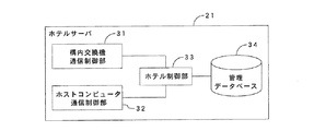
ホテルサーバ21は、図6に示すように、構内交換機通信制御部31、ホストコンピュータ通信制御部32、ホテル制御部33及び管理データベース34で構成される。ホテル制御部33は、例えば、この構内交換システム50に対してホテルを新規に追加する際に、ホテルに設置された電話機と接続する構内交換機を決定する。尚、その際には、一部の構内交換機に負荷が集中しないように、例えば、この構内交換システム50に対してホテルを新規に追加する毎に、複数の構内交換機を順番に対応付けるように決定すると好ましい。
As shown in FIG. 6, the
管理データベース34には、ホテルを識別するホテルIDと、ホテルに対応付けられた構内交換機を識別する交換機IDと、ホテルに割り当てられた内線番号の番号帯と、客室利用者に関する客室情報とが互いに関連付けられて登録される。
In the
次に、上記構成を有する構内交換システム50の動作について説明する。通常時には、この構内交換システム50が導入されている各ホテルに対して、ホテルサーバ21のホテル制御部33によりホテルID及び番号帯が予め割り当てられると共に、各構内交換機に対して交換機IDが予め割り当てられる。
Next, the operation of the private
また、管理データベース34には、ホテルID、交換機ID及び番号帯が関連付けられて登録される。そして、構内交換機22A及び22Bは、同一番号帯による通話のみが可能となるように設定される。このような状態では、同一番号帯間における通話のみが可能となり、異なる番号帯間における通話が不可となる。
In the
次に、構内交換システム50に対して別のホテルを新規に追加する場合について説明する。ここでは、説明を容易とするため、構内交換システム50に対してホテル2Aを新規に追加する場合を例にとって説明する。
Next, a case where another hotel is newly added to the private
ホテル2Aに設置されたホストコンピュータ13Aからホテルサーバ21に対して接続要求が送信されると、ホテルサーバ21のホストコンピュータ通信制御部32とホストコンピュータ13Aとがインターネット回線4Bを介して接続される。ホストコンピュータ13Aからの接続要求は、ホテルサーバ21のホストコンピュータ通信制御部32で受信され、ホストコンピュータ通信制御部32は、受信した接続要求をホテル制御部33に供給する。
When a connection request is transmitted from the
ホテル制御部33は、ホストコンピュータ13Aからの接続要求を受け取ると、ホストコンピュータ13Aに対してホテルIDを割り当てると共に、ホテル2Aで使用される番号帯を決定する。また、ホテル制御部33は、ホテル2Aに設置された電話機11Aと接続する構内交換機を決定する。この例では、電話機11Aと構内交換機22Aとが接続される。そして、ホテル制御部33は、ホテル2Aに対して割り当てたホテルID及び番号帯と、構内交換機22Aの交換機IDとを互いに関連付けて管理データベース34に登録する。
Upon receiving a connection request from the
次に、構内交換機通信制御部31と構内交換機22Aとが接続され、ホテル制御部33は、ホテル2Aに対して割り当てた番号帯間における通話を可能とすると共に、この番号帯と別のホテルに対して割り当てた番号帯との間における通話を不可とするよう、ホテル2AのホテルIDと関連付けて管理データベース34に登録された交換機IDに対応する構内交換機22Aに対して通知する。
Next, the private branch exchange
構内交換機22Aは、ホテルサーバ21から受信した通知に基づき、接続回線を設定する。これにより、ホテル2Aの電話機11A同士での通話のみが可能となり、電話機11Aと、構内交換機22Aに接続された他のホテルの電話機との間における通話は不可となる。
The
このように、複数の構内交換機を交換機IDを用いて識別することにより、例えば、ホテル内のホストコンピュータからホテルサーバを介して構内交換機にデータを送信する際に、送信先の構内交換機を間違えることなく、データを適切に送信することができる。 Thus, by identifying a plurality of private branch exchanges using the exchange ID, for example, when transmitting data from the host computer in the hotel to the private branch exchange via the hotel server, the destination private branch exchange is mistaken. And data can be transmitted appropriately.
以上のように、第3の実施形態によれば、複数の構内交換機に対して交換機IDを割り当て、交換機IDに基づき各ホテルの電話に対応する構内交換機を決定するため、複数の交換機と複数のホストコンピュータとを接続しながら、既存のサービスやセキュリティを提供することができる。 As described above, according to the third embodiment, a switch ID is assigned to a plurality of private branch exchanges, and a private branch exchange corresponding to each hotel telephone is determined based on the switch ID. Existing services and security can be provided while connecting to the host computer.
また、複数の構内交換機をホテルの外部に設置するため、第1及び第2の実施形態と同様に、従来、各ホテルに設置していた構内交換機による占有スペースを削減することができ、コストを削減することができる。 Moreover, since a plurality of private branch exchanges are installed outside the hotel, the space occupied by the private branch exchanges conventionally installed in each hotel can be reduced, as in the first and second embodiments, and the cost can be reduced. Can be reduced.
以上、本発明の第1、第2及び第3の実施形態について説明したが、本発明は、上述した本発明の第1、第2及び第3の実施形態に限定されるものではなく、本発明の要旨を逸脱しない範囲内で様々な変形や応用が可能である。例えば、上述の例では、構内交換システムをホテルに適用した場合について説明したが、これに限られず、利用者に対して客室や個室を提供する旅館や研修センター等の施設に対しても、この構内交換システムを適用することができる。 The first, second, and third embodiments of the present invention have been described above. However, the present invention is not limited to the above-described first, second, and third embodiments of the present invention, and the present invention is not limited thereto. Various modifications and applications are possible without departing from the scope of the invention. For example, in the above-mentioned example, the case where the private branch exchange system is applied to a hotel has been described. However, the present invention is not limited to this, and this is also applicable to facilities such as inns and training centers that provide guest rooms and private rooms to users. A private branch exchange system can be applied.
1、40、50 構内交換システム
2(2A、2B、2C) ホテル
3 データセンター
4(4A、4B) インターネット回線
11(11A、11B、11C) 電話機
12(12A、12B、12C) 中継台
13(13A、13B、13C) ホストコンピュータ
14 ルームインジケータ
21、41 ホテルサーバ
22、22A、22B 構内交換機
31 構内交換機通信制御部
32 ホストコンピュータ通信制御部
33 ホテル制御部
34 管理データベース
42 客室留守番電話
43 ルームインジケータ通信制御部
51(51A、51B) インターネット回線
100 構内交換システム
101 PBX
102 ホストコンピュータ
103 端末接続装置
104(104A、104B) 電話機
110 CPU
111 コンピュータ回線
111a 通信路
111b 端末制御情報路
111c 特殊データ伝送路
112 端末回線
112a 通信路
112b 制御情報路
120 構内交換システム
121A ネットワークコントロールノード
121B、121C ローカルネットワークノード
122(122A、122B、122C) ホストコンピュータ
123 サーバ
124(124A、124B) 電話機
125 中継台
130 インターネット回線
131(131A、131B、131C) 通信路スイッチ
132(132A、132B、132C) 通信制御部
133(133A、133B、133C) ローカル局データ
134(134A、134B、134C) ネットワーク局データ
141 データベース
142 イベント転送回路
1, 40, 50 Private branch exchange system 2 (2A, 2B, 2C)
102
111 Computer line 111a Communication path 111b Terminal control information path 111c Special data transmission path 112 Terminal line 112a Communication path 112b
Claims (4)
客室毎に設けられ、外部又は他の客室との通話を行う電話機と、
前記客室の在室状態を表示するルームインジケータとが1つ又は複数の施設の各々に設置され、
前記ホストコンピュータと接続され、該ホストコンピュータとの間での前記客室情報の送受信及び該客室情報の管理を行うサーバと、
前記電話機及び前記サーバに接続され、電話交換処理を行う構内交換機と、
前記サーバ及び前記構内交換機に接続され、メッセージを記憶する留守番電話機とが前記1つ又は複数の施設とは異なる他の施設に設置され、
前記サーバは、
前記1つ又は複数の施設の各々を識別する施設識別情報及び前記1つ又は複数の施設の電話機に対する内線番号の番号帯を割り当てると共に、前記客室情報を管理する制御部と、
前記施設識別情報及び前記番号帯を関連付けて記憶するデータベースとを有し、
前記制御部は、前記施設識別情報と前記ホストコンピュータから送信された前記客室情報とを関連付けて前記データベースに登録し、
前記構内交換機は、同一の番号帯間での通話のみが可能となるように設定し、
前記ルームインジケータは、前記客室の在室状態を示す客室在室情報を前記サーバに送信し、
前記サーバは、前記制御部により、受信した前記客室在室情報を前記ルームインジケータが設置された施設に対して割り当てられた前記施設識別情報と関連付けて前記データベースに登録すると共に、前記客室在室情報を前記構内交換機に送信し、
前記構内交換機は、受信した前記客室在室情報が前記客室の不在を示す場合に、前記不在状態の客室に設置された電話機に対する着信を前記留守番電話機に転送するように設定し、
前記サーバは、前記制御部により、前記留守番電話機にメッセージが記憶された場合に、該メッセージが記憶されたことを示す情報を、前記施設識別情報に関連付けられた前記客室情報に追加して登録することを特徴とする構内交換システム。 A host computer that processes room information about the room users;
A telephone set provided for each guest room for making a call to the outside or another guest room ;
A room indicator that displays the occupancy status of the guest room is installed in each of one or more facilities,
A server connected to the host computer for transmitting / receiving the room information to / from the host computer and managing the room information;
A private branch exchange connected to the telephone and the server for performing telephone exchange processing ;
An answering machine connected to the server and the private branch exchange and storing a message is installed in another facility different from the one or more facilities,
The server
A controller for assigning facility identification information for identifying each of the one or more facilities and an extension number band for the telephones of the one or more facilities, and managing the guest room information;
A database that stores the facility identification information and the number band in association with each other;
The control unit associates the facility identification information with the guest room information transmitted from the host computer and registers it in the database,
The private branch exchange is set so that only calls between the same number bands are possible ,
The room indicator transmits guest room occupancy information indicating the occupancy status of the guest room to the server,
The server registers the received room occupancy information received by the control unit in the database in association with the facility identification information assigned to the facility where the room indicator is installed, and the room occupancy information. To the private branch exchange,
The private branch exchange is configured to transfer an incoming call to a telephone set in the absent guest room to the answering machine when the received room presence information indicates the absence of the guest room,
When the control unit stores a message in the answering machine, the server registers information indicating that the message has been stored in addition to the room information associated with the facility identification information. A private branch exchange system.
前記構内交換機は、前記電話機に対する操作に基づくモーニングコールを設定すると共に、前記モーニングコールが設定されたことを示す設定情報を前記サーバに送信し、
前記サーバは、前記制御部により、受信した前記設定情報を前記モーニングコールが設定された電話機が設置された施設に対して割り当てられた前記施設識別情報と関連付けて前記データベースに登録し、
前記設定情報を、対応する施設識別情報が割り当てられた施設の前記ホストコンピュータに送信することを特徴とする請求項1に記載の構内交換システム。 When a wake-up call is set by operating the phone,
The private branch exchange sets a wake-up call based on an operation on the telephone, and transmits setting information indicating that the wake-up call is set to the server,
The server registers, in the database, the setting information received by the control unit in association with the facility identification information assigned to the facility where the telephone set with the wake-up call is installed,
The private branch exchange system according to claim 1, wherein the setting information is transmitted to the host computer of the facility to which the corresponding facility identification information is assigned.
前記サーバは、前記制御部により、受信した前記実行情報を前記モーニングコールが実行された電話機が設置された施設に対して割り当てられた前記施設識別情報と関連付けて前記データベースに登録し、
前記実行情報を、対応する施設識別情報が割り当てられた施設の前記ホストコンピュータに送信することを特徴とする請求項2に記載の構内交換システム。 When the private branch exchange executes the wake-up call, it sends execution information indicating the wake-up call execution result to the server,
The server registers the execution information received by the control unit in the database in association with the facility identification information assigned to the facility where the telephone on which the wake-up call is executed is installed,
The private branch exchange system according to claim 2 , wherein the execution information is transmitted to the host computer of the facility to which the corresponding facility identification information is assigned.
前記制御部は、前記複数の構内交換機を識別するための交換機識別情報を割り当てると共に、前記複数の構内交換機のうち、前記1つ又は複数の施設の各々に対応する構内交換機を決定し、
前記施設識別情報と、対応付けられた構内交換機に割り当てられた前記交換機識別情報とを関連付けて前記データベースに登録することを特徴とする請求項1、2又は3に記載の構内交換システム。 A plurality of private branch exchanges are installed in the other facility,
The control unit assigns exchange identification information for identifying the plurality of private branch exchanges, and determines a private branch exchange corresponding to each of the one or more facilities among the plurality of private branch exchanges,
4. The private branch exchange system according to claim 1 , wherein the facility identification information and the exchange identification information assigned to the associated private branch exchange are associated with each other and registered in the database.
Priority Applications (1)
| Application Number | Priority Date | Filing Date | Title |
|---|---|---|---|
| JP2011063900A JP5455246B2 (en) | 2011-03-23 | 2011-03-23 | Private branch exchange system |
Applications Claiming Priority (1)
| Application Number | Priority Date | Filing Date | Title |
|---|---|---|---|
| JP2011063900A JP5455246B2 (en) | 2011-03-23 | 2011-03-23 | Private branch exchange system |
Publications (2)
| Publication Number | Publication Date |
|---|---|
| JP2012199866A JP2012199866A (en) | 2012-10-18 |
| JP5455246B2 true JP5455246B2 (en) | 2014-03-26 |
Family
ID=47181627
Family Applications (1)
| Application Number | Title | Priority Date | Filing Date |
|---|---|---|---|
| JP2011063900A Expired - Fee Related JP5455246B2 (en) | 2011-03-23 | 2011-03-23 | Private branch exchange system |
Country Status (1)
| Country | Link |
|---|---|
| JP (1) | JP5455246B2 (en) |
Family Cites Families (11)
| Publication number | Priority date | Publication date | Assignee | Title |
|---|---|---|---|---|
| JPH03218153A (en) * | 1990-01-24 | 1991-09-25 | Oki Electric Ind Co Ltd | Proxy system in absence for voice mail system |
| JPH04339493A (en) * | 1991-02-28 | 1992-11-26 | Matsushita Electric Ind Co Ltd | Distributed private branch exchange equipment |
| JPH0530563A (en) * | 1991-07-18 | 1993-02-05 | Fujitsu Ltd | Private branch exchange |
| JP3351817B2 (en) * | 1992-06-11 | 2002-12-03 | 株式会社日立テレコムテクノロジー | Variable direct line destination system |
| JP2001250006A (en) * | 2000-03-03 | 2001-09-14 | Primelink:Kk | Hotel lodging reserving system |
| JP2002044264A (en) * | 2000-07-31 | 2002-02-08 | Nec Eng Ltd | Room information indication system of translator connected to private branch exchange |
| JP3592231B2 (en) * | 2000-11-24 | 2004-11-24 | 日本電気エンジニアリング株式会社 | Hotel private branch exchange system |
| JP2002300623A (en) * | 2001-04-02 | 2002-10-11 | Nec Eng Ltd | Telephone exchange system |
| JP2002352003A (en) * | 2001-05-25 | 2002-12-06 | Suwifuto Agent:Kk | System for providing unoccupied room information of hotel |
| JP2004080470A (en) * | 2002-08-20 | 2004-03-11 | Nec Engineering Ltd | Phone reception system |
| JP2010087815A (en) * | 2008-09-30 | 2010-04-15 | Marks Kk | Phone system |
-
2011
- 2011-03-23 JP JP2011063900A patent/JP5455246B2/en not_active Expired - Fee Related
Also Published As
| Publication number | Publication date |
|---|---|
| JP2012199866A (en) | 2012-10-18 |
Similar Documents
| Publication | Publication Date | Title |
|---|---|---|
| JP5164583B2 (en) | Telephone system | |
| JPH08214346A (en) | Priority order control method for automatic distribution of incoming call | |
| JP2001186196A (en) | Telephone communication equipment and main telephone controller capable of communication by the internet | |
| JP5455246B2 (en) | Private branch exchange system | |
| JP4132601B2 (en) | Incoming call control apparatus and method | |
| JP2847039B2 (en) | Incoming call notification system and information processing system used therefor | |
| JP2007295020A (en) | Remote monitoring system | |
| JP5751076B2 (en) | Telephone transfer device and telephone transfer program | |
| JP5572977B2 (en) | Telephone system and telephone control method | |
| JP2009182816A (en) | Telephone business system | |
| JP2006245889A (en) | Information providing system and information providing apparatus | |
| JP6126263B1 (en) | COMMUNICATION SYSTEM, NETWORK DEVICE, CONTROL METHOD, AND CONTROL PROGRAM | |
| JPH1056511A (en) | Automatic incoming call distributor | |
| JP2000152295A (en) | Private telephone system | |
| WO2024095347A1 (en) | Web phone system, server device for web phone, and program for web phone | |
| US11496420B2 (en) | Contact system and non-transitory computer readable medium storing contact program | |
| JP5665108B2 (en) | Telephone exchange system and telephone switching method | |
| JP6972679B2 (en) | Telephone control device, telephone terminal, linked PC, telephone system, and telephone directory registration method | |
| JP2001189948A (en) | Key telephone system | |
| JP2603725B2 (en) | Call state transition notification method | |
| JP2022116499A (en) | Information processing device, telephone system, extension number identification method, and program | |
| JP2004080470A (en) | Phone reception system | |
| JP3991646B2 (en) | Setting information management system, button telephone device, and service center device | |
| JP2507610B2 (en) | Terminal state transition notification method | |
| JP4961930B2 (en) | Telephone system and telephone control device |
Legal Events
| Date | Code | Title | Description |
|---|---|---|---|
| A977 | Report on retrieval |
Free format text: JAPANESE INTERMEDIATE CODE: A971007 Effective date: 20130404 |
|
| A131 | Notification of reasons for refusal |
Free format text: JAPANESE INTERMEDIATE CODE: A131 Effective date: 20130409 |
|
| TRDD | Decision of grant or rejection written | ||
| A01 | Written decision to grant a patent or to grant a registration (utility model) |
Free format text: JAPANESE INTERMEDIATE CODE: A01 Effective date: 20131210 |
|
| A61 | First payment of annual fees (during grant procedure) |
Free format text: JAPANESE INTERMEDIATE CODE: A61 Effective date: 20140106 |
|
| R150 | Certificate of patent or registration of utility model |
Free format text: JAPANESE INTERMEDIATE CODE: R150 |
|
| LAPS | Cancellation because of no payment of annual fees |