JP5453404B2 - System for performing surface electromyography and joint range of motion tests - Google Patents
System for performing surface electromyography and joint range of motion tests Download PDFInfo
- Publication number
- JP5453404B2 JP5453404B2 JP2011512562A JP2011512562A JP5453404B2 JP 5453404 B2 JP5453404 B2 JP 5453404B2 JP 2011512562 A JP2011512562 A JP 2011512562A JP 2011512562 A JP2011512562 A JP 2011512562A JP 5453404 B2 JP5453404 B2 JP 5453404B2
- Authority
- JP
- Japan
- Prior art keywords
- patient
- semg
- joint
- along
- hub
- Prior art date
- Legal status (The legal status is an assumption and is not a legal conclusion. Google has not performed a legal analysis and makes no representation as to the accuracy of the status listed.)
- Active
Links
Images


Classifications
-
- A—HUMAN NECESSITIES
- A61—MEDICAL OR VETERINARY SCIENCE; HYGIENE
- A61B—DIAGNOSIS; SURGERY; IDENTIFICATION
- A61B5/00—Measuring for diagnostic purposes; Identification of persons
- A61B5/24—Detecting, measuring or recording bioelectric or biomagnetic signals of the body or parts thereof
- A61B5/316—Modalities, i.e. specific diagnostic methods
- A61B5/389—Electromyography [EMG]
-
- A—HUMAN NECESSITIES
- A61—MEDICAL OR VETERINARY SCIENCE; HYGIENE
- A61B—DIAGNOSIS; SURGERY; IDENTIFICATION
- A61B5/00—Measuring for diagnostic purposes; Identification of persons
- A61B5/103—Detecting, measuring or recording devices for testing the shape, pattern, colour, size or movement of the body or parts thereof, for diagnostic purposes
- A61B5/11—Measuring movement of the entire body or parts thereof, e.g. head or hand tremor, mobility of a limb
- A61B5/1121—Determining geometric values, e.g. centre of rotation or angular range of movement
-
- A—HUMAN NECESSITIES
- A61—MEDICAL OR VETERINARY SCIENCE; HYGIENE
- A61B—DIAGNOSIS; SURGERY; IDENTIFICATION
- A61B5/00—Measuring for diagnostic purposes; Identification of persons
- A61B5/45—For evaluating or diagnosing the musculoskeletal system or teeth
- A61B5/4538—Evaluating a particular part of the muscoloskeletal system or a particular medical condition
- A61B5/4561—Evaluating static posture, e.g. undesirable back curvature
-
- A—HUMAN NECESSITIES
- A61—MEDICAL OR VETERINARY SCIENCE; HYGIENE
- A61B—DIAGNOSIS; SURGERY; IDENTIFICATION
- A61B5/00—Measuring for diagnostic purposes; Identification of persons
- A61B5/68—Arrangements of detecting, measuring or recording means, e.g. sensors, in relation to patient
- A61B5/6801—Arrangements of detecting, measuring or recording means, e.g. sensors, in relation to patient specially adapted to be attached to or worn on the body surface
- A61B5/6813—Specially adapted to be attached to a specific body part
- A61B5/6823—Trunk, e.g., chest, back, abdomen, hip
-
- A—HUMAN NECESSITIES
- A61—MEDICAL OR VETERINARY SCIENCE; HYGIENE
- A61B—DIAGNOSIS; SURGERY; IDENTIFICATION
- A61B5/00—Measuring for diagnostic purposes; Identification of persons
- A61B5/68—Arrangements of detecting, measuring or recording means, e.g. sensors, in relation to patient
- A61B5/6801—Arrangements of detecting, measuring or recording means, e.g. sensors, in relation to patient specially adapted to be attached to or worn on the body surface
- A61B5/6813—Specially adapted to be attached to a specific body part
- A61B5/6825—Hand
-
- A—HUMAN NECESSITIES
- A61—MEDICAL OR VETERINARY SCIENCE; HYGIENE
- A61B—DIAGNOSIS; SURGERY; IDENTIFICATION
- A61B2562/00—Details of sensors; Constructional details of sensor housings or probes; Accessories for sensors
- A61B2562/02—Details of sensors specially adapted for in-vivo measurements
- A61B2562/0219—Inertial sensors, e.g. accelerometers, gyroscopes, tilt switches
-
- A—HUMAN NECESSITIES
- A61—MEDICAL OR VETERINARY SCIENCE; HYGIENE
- A61B—DIAGNOSIS; SURGERY; IDENTIFICATION
- A61B5/00—Measuring for diagnostic purposes; Identification of persons
- A61B5/45—For evaluating or diagnosing the musculoskeletal system or teeth
- A61B5/4528—Joints
Description
〔関連出願との相互参照〕
本出願は、2008年6月2日に出願された米国仮特許出願第61/058,160号に基づき、その利益を本明細書によって主張する一般特許出願であり、該仮特許出願の開示内容はその全体が引用により本明細書に組み入れられる。
[Cross-reference with related applications]
This application is a general patent application that claims its benefit based on US Provisional Patent Application No. 61 / 058,160 filed on June 2, 2008, and the disclosure of the provisional patent application. Is incorporated herein by reference in its entirety.
本発明は、医療診断用器具に関する。本発明はまた、表面筋電図検査又は関節可動域検査を別々に、又は互いに組み合わせて使用して軟部組織損傷を評価するためのシステム及び方法にも関する。 The present invention relates to a medical diagnostic instrument. The present invention also relates to systems and methods for assessing soft tissue damage using surface electromyography or joint range of motion examinations separately or in combination with each other.
軟部組織損傷(例えば、筋肉、腱、靭帯、筋膜、神経、繊維組織、脂肪、血管、滑膜組織などを含む人体の構造及び器官を接続し、支持し、又は取り囲む組織の損傷など)を診断したり、軟部組織損傷に関連する痛みを判断したりすることは困難なことがある。軟部組織損傷は肉眼で見えないことが多い。また、軟部組織損傷は、磁気共鳴映像法、コンピュータ断層撮影法、超音波などの画像診断技術をもってしても判断が難しい(かつ費用が掛かる)場合がある。 Soft tissue damage (eg, damage to tissue that connects, supports or surrounds the structure and organs of the human body, including muscle, tendon, ligament, fascia, nerve, fibrous tissue, fat, blood vessels, synovial tissue, etc.) It can be difficult to diagnose and determine the pain associated with soft tissue damage. Soft tissue damage is often invisible to the naked eye. In addition, soft tissue damage may be difficult to determine (and expensive) even with diagnostic imaging techniques such as magnetic resonance imaging, computed tomography, and ultrasound.
以下の図面を参照しながら本発明の非限定的かつ非包括的な実施形態について説明する。図面では、特に指定しない限り様々な図を通じて同じ参照番号が同じ部分を示す。 Non-limiting and non-inclusive embodiments of the invention are described with reference to the following drawings. In the drawings, like reference numerals refer to like parts throughout the various figures unless otherwise specified.
本発明をより良く理解できるように、以下の詳細な説明を添付図面と併せて参照されたい。 For a better understanding of the present invention, reference should be made to the following detailed description taken in conjunction with the accompanying drawings.
本発明は、医療診断用器具に関する。本発明はまた、表面筋電図検査又は関節可動域検査を別々に、又は互いに組み合わせて使用して軟部組織損傷を評価するためのシステム及び方法にも関する。 The present invention relates to a medical diagnostic instrument. The present invention also relates to systems and methods for assessing soft tissue damage using surface electromyography or joint range of motion examinations separately or in combination with each other.
本明細書で説明する方法、システム及び装置は、多くの異なる形で具体化することができ、これらを本明細書に示す実施形態に限定されると解釈すべきではない。従って、本明細書で説明する方法、システム及び装置は、完全にハードウェアの実施形態、完全にソフトウェアの実施形態、又はソフトウェアとハードウェアの態様を組み合わせた実施形態の形を取ることができる。本明細書で説明する方法は、プロセッサを含むコンピュータなどのあらゆる種類の計算装置、又は個々の装置がプロセスの少なくとも一部を実施する計算装置のあらゆる組み合わせを使用して実施することができる。 The methods, systems, and apparatus described herein can be embodied in many different forms and should not be construed as limited to the embodiments set forth herein. Accordingly, the methods, systems, and apparatus described herein can take the form of an entirely hardware embodiment, an entirely software embodiment or an embodiment combining software and hardware aspects. The methods described herein can be implemented using any type of computing device, such as a computer including a processor, or any combination of computing devices in which individual devices perform at least a portion of the process.
通常、適当な計算装置は大容量記憶装置を含むとともに、装置間の通信を含む。大容量記憶装置は、ある種のコンピュータ可読媒体、すなわちコンピュータ記憶媒体のことを示す。コンピュータ記憶媒体は、コンピュータ可読命令、データ構造、プログラムモジュール、又は他のデータなどの情報を記憶するためのあらゆる方法又は技術において実装される揮発性、不揮発性、取り外し可能、及び取り外し不能媒体を含むことができる。コンピュータ記憶媒体の例として、RAM、ROM、EEPROM、フラッシュメモリ又はその他のメモリ技術、CD−ROM、デジタル多機能ディスク(DVD)又はその他の光学記憶装置、磁気カセット、磁気テープ、磁気ディスク記憶装置又はその他の磁気記憶装置、或いは所望の情報の記憶に使用できるとともにコンピュータ装置がアクセスできる他のいずれかの媒体が挙げられる。 Suitable computing devices typically include mass storage devices as well as communication between devices. Mass storage refers to some kind of computer readable media, ie computer storage media. Computer storage media includes volatile, nonvolatile, removable, and non-removable media implemented in any method or technique for storing information such as computer readable instructions, data structures, program modules, or other data. be able to. Examples of computer storage media include RAM, ROM, EEPROM, flash memory or other memory technology, CD-ROM, digital multifunction disk (DVD) or other optical storage device, magnetic cassette, magnetic tape, magnetic disk storage device or Other magnetic storage devices, or any other medium that can be used to store desired information and that can be accessed by a computer device.
装置間又はシステムの構成要素間の通信の方法は、有線通信方法及び(RF、光又は赤外線などの)無線通信方法の両方を含むことができ、このような方法により、別の種類のコンピュータ可読媒体すなわち通信媒体が実現される。通常、通信媒体は、コンピュータ可読命令、データ構造、プログラムモジュール又はその他のデータを搬送波などの変調データ信号、データ信号、又はその他の搬送機構の形で具体化し、いずれかの情報配信媒体を含む。「変調データ信号」及び「搬送波信号」という用語は、特性の1又はそれ以上が、信号に含まれる情報、命令、データなどを符号化するように設定又は変更された信号を含む。一例として、通信媒体には、ツイストペア、同軸ケーブル、光ファイバ、導波管及びその他の有線媒体などの有線媒体、及び音響、RF、赤外線及びその他の無線媒体などの無線媒体が含まれる。 Methods of communication between devices or between system components can include both wired communication methods and wireless communication methods (such as RF, optical or infrared), which allow for another type of computer readable. A medium or communication medium is realized. Communication media typically embodies computer readable instructions, data structures, program modules or other data in the form of a modulated data signal such as a carrier wave, data signal, or other transport mechanism and includes any information delivery media. The terms “modulated data signal” and “carrier signal” include signals that have one or more of their characteristics set or changed in such a manner as to encode information, instructions, data, etc. included in the signal. By way of example, communication media includes wired media such as twisted pairs, coaxial cables, optical fibers, waveguides and other wired media, and wireless media such as acoustic, RF, infrared and other wireless media.
軟部組織損傷を診断する際に役立つことができる、1又はそれ以上の患者の能力を測定する医療診断用装置が、長年にわたって数種類開発されてきた。1つのこのような種類の医療診断用装置に表面筋電計(「sEMG」)があり、この装置を使用して、患者が様々な運動を行っている間(例えば動的sEMG)の、又は患者が休息している間(例えば静的sEMG)の、患者の選択した筋群の筋緊張を測定することができる。別のこのような種類の医療診断用装置に関節可動域テスター(「ROM」)があり、この装置を使用して、患者が所定の関節に沿ってどこまで曲げられるかを測定することができる。しかしながら、sEMG技術及びROM技術が進歩したにもかかわらず、軟部組織損傷を完璧に診断し、対応する患者の痛みを判断するツールは相変わらず実現が難しい。 Several types of medical diagnostic devices that measure the ability of one or more patients that can be useful in diagnosing soft tissue damage have been developed over the years. One such type of medical diagnostic device is a surface electromyograph (“sEMG”) that can be used while the patient is performing various exercises (eg, dynamic sEMG), or While the patient is resting (eg, static sEMG), the muscle tone of the selected muscle group of the patient can be measured. Another such type of medical diagnostic device is a range of motion tester ("ROM"), which can be used to measure how far a patient is bent along a given joint. However, despite advances in sEMG technology and ROM technology, tools that perfectly diagnose soft tissue damage and determine corresponding patient pain remain difficult to implement.
軟部組織損傷を確実に診断又は判断できなければ、患者の損傷の種類によっては誤診が生じ、結果的に不適切な治療を施すことにより医療制度が金銭的負担を被る恐れがある。また、金銭又はその他の形の対価を受け取るために偽って軟部組織損傷を主張する(或いはその程度を大幅に誇張する)人々の存在により、保険制度及び法廷制度も同様に金銭的負担を被る恐れがある。 If soft tissue damage cannot be reliably diagnosed or judged, misdiagnosis may occur depending on the type of damage to the patient, and as a result, the medical system may suffer a financial burden due to improper treatment. In addition, the insurance and forensic systems may be similarly financially burdened by the presence of people who falsely claim soft tissue damage (or greatly exaggerate the extent) in order to receive money or other forms of consideration. There is.
少なくともいくつかの実施形態では、軟部組織損傷診断システム(「診断システム」)を使用して、ROM検査、動的sEMG検査及び静的sEMG検査を含む1又はそれ以上の診断検査を単独で又は組み合わせて患者に行うことができる。少なくともいくつかの実施形態では、診断システムが1又はそれ以上のビデオカメラも含む。少なくともいくつかの実施形態では、複数のビデオカメラを使用して、上述した検査の1又はそれ以上を受けている間の患者の動きのビデオ(又は写真)を取り込むことができる。少なくともいくつかの実施形態では、これらの検査の1又はそれ以上から得られる結果を1又はそれ以上の医師が使用して、軟部組織損傷を診断又は判断することができる。 In at least some embodiments, a soft tissue injury diagnostic system (“diagnostic system”) is used to singly or combine one or more diagnostic tests, including ROM tests, dynamic sEMG tests, and static sEMG tests. Can be performed on the patient. In at least some embodiments, the diagnostic system also includes one or more video cameras. In at least some embodiments, multiple video cameras can be used to capture a video (or photo) of patient motion while undergoing one or more of the above-described examinations. In at least some embodiments, results from one or more of these tests can be used by one or more physicians to diagnose or determine soft tissue damage.
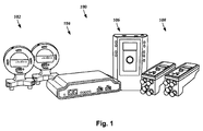
図1は、診断システム100の一実施形態の概略斜視図である。診断システム100は、患者にROM検査を行う(患者がどこまで曲げられるかを検査する)ための傾斜計102と、ハブ104と、患者に動的sEMG検査を行う際に使用する(患者が様々な動きを行ったときの筋群に沿った活動電位を測定する)ための動的sEMG制御モジュール(「sEMGモジュール」)106と、患者に静的sEMG検査を行う(患者が所定の姿勢を保持しているときの筋群に沿った活動電位を測定する)ための静的sEMGスキャナ(「スキャナ」)108とを含む。
FIG. 1 is a schematic perspective view of one embodiment of a
少なくともいくつかの実施形態では、傾斜計102、動的sEMGモジュール106及びスキャナ108が、ハブ104と電気的に通信する。いくつかの実施形態では、傾斜計102、動的sEMGモジュール106及びスキャナ108の1又はそれ以上が、3Gなどの無線ネットワークによりハブ104に電気的に結合される。他の実施形態では、傾斜計102、動的sEMGモジュール106及びスキャナ108の1又はそれ以上が、ワイヤなどの1又はそれ以上の導体によりハブ104に電気的に結合される。
In at least some embodiments,
少なくともいくつかの実施形態では、診断システム100がまた、(図2に示すように)1又はそれ以上プロセッサ202と、1又はそれ以上の視覚ディスプレイ204と、1又はそれ以上のビデオカメラ206とを含む。少なくともいくつかの実施形態では、ハブ104が1又はそれ以上のプロセッサ202に電気的に結合される。少なくともいくつかの実施形態では、1又はそれ以上のプロセッサ202が、傾斜計102、動的sEMGモジュール106又はスキャナ108から(ハブ104を介して)入力データを受信して処理し、この処理したデータの結果を1又はそれ以上の視覚ディスプレイ204上に表示する。少なくともいくつかの実施形態では、ROM検査、動的sEMG検査又は静的sEMG検査の1又はそれ以上の少なくとも一部が、1又はそれ以上のビデオカメラ206により視覚的に取り込まれる。
In at least some embodiments, the
少なくともいくつかの実施形態では、診断システム100が、例えば、傾斜計102、動的sEMGモジュール106又はスキャナ108をハブ104に繋ぐこと、ROM検査、動的sEMG及び静的sEMGを行うこと、ROM検査、動的sEMG又は静的sEMGの結果を表示すること、検査データを保存してバックアップすること、及び検査装置の電源をオン又はオフすることを含む多くの異なる作業を容易にするためのソフトウェア又はハードウェアを含む。
In at least some embodiments, the
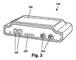
図3はハブ104の概略正面図である。少なくともいくつかの実施形態では、ハブ104が、傾斜計102、動的sEMGモジュール106又はスキャナ108をハブ104に結合するための1又はそれ以上の入力部302を含む。少なくともいくつかの実施形態では、ハブ104が、(キーボード、マウス、モニタ、プリンタ、記憶装置などの)1又はそれ以上の周辺機器のための入力部304も含む。少なくともいくつかの実施形態では、ハブ104が、(ディスプレイ、キーパッドなどの)1又はそれ以上のユーザインターフェイス306を含む。少なくともいくつかの実施形態では、ハブ104が、電源インジケータ、接続性インジケータなどの1又はそれ以上のインジケータ308を含む。少なくともいくつかの実施形態では、複数のハブ104を並列又は直列で利用することができる。少なくともいくつかの実施形態では、1又はそれ以上のハブ104が、傾斜計102、動的sEMGモジュール106又はスキャナ108からの入力データを受信して処理し、ハブ104に結合された(又はこの上に配置された)LCDなどのディスプレイ上に結果を表示する。少なくともいくつかの実施形態では、1又はそれ以上のハブ104が、情報を入力するためのキーパッドを含む。
FIG. 3 is a schematic front view of the
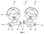
図4は、診断システム100の傾斜計102の一実施形態の概略正面図である。傾斜計102は、メインユニット402及び補助ユニット404を含む。少なくともいくつかの実施形態では、メインユニット402及び補助ユニット404が各々実質的に円盤形であり、円盤の底部から接線方向に延びる平坦な底面406と結合される。少なくとも1つの実施形態では、平坦な底面406が2又はそれ以上の足部408を含む。少なくともいくつかの実施形態では、足部408が、これらの間の距離を調整できるように平坦な底面406に沿って独立して摺動することができる。
FIG. 4 is a schematic front view of one embodiment of the
少なくともいくつかの実施形態では、メインユニット402及び補助ユニット404が各々、メインユニット402及び補助ユニット404の本体上に位置するLED410などの、度数マーキングを形成するための複数の発光ダイオード(「LED」)を含む。例えば、メインユニット402又は補助ユニット404を平坦な底面406上に直立姿勢で置いたときに、0°、90°、180°及び270°を示すようにLEDを配置することができる。少なくともいくつかの実施形態では、ユーザがLEDを使用してメインユニット402と補助ユニット404の間の相対角度を判定し、コンピュータディスプレイを見てこの情報を得る必要がないようにすることができる。少なくともいくつかの実施形態では、LEDを使用して、メインユニット402と補助ユニット404の間の回転度を重力に基づいて示すようにすることができる。
In at least some embodiments, the
少なくともいくつかの実施形態では、メインユニット402及び補助ユニット404が加速度計を使用する。LEDの度数マーキング及び加速度計を使用することにより、ユーザが正確な水準(気泡式水準)を使用して傾斜計102を正確な地心に較正し、その後LEDを使用して重力に関して正確なゼロを示すことができるようになる。
In at least some embodiments,
少なくともいくつかの実施形態では、このLEDにより、ユーザがメインユニット402又は補助ユニット404を見ることによって、これらのユニットがいつ地心の無重力から様々な度数にあるかを知ることができるようになる。これにより、ユーザは、手動による視覚的な振り子(いくつかの従来の装置が現在も採用している技術である)を使用せずに電子的に測定を行えるようになる。この角度データがハブ104又は1又はそれ以上のプロセッサ202により記憶され、人間が度数を計算する必要がなくなるので、結果的に時間が節約できるとともに、より正確な読み取りを行うことができる。
In at least some embodiments, this LED allows the user to see when these units are in varying degrees from geocentric weightlessness by looking at
少なくともいくつかの実施形態では、1又はそれ以上のLED点滅システムを実装して、ROM検査の実施中にメインユニット402又は補助ユニット404が何度にあるかをユーザに伝えることができる。例えば、1又はそれ以上のLEDが0°、90°、180°及び270°を示すように構成した場合、(単複の)LEDがユーザに以下のようなフィードバックを提供することができる。メインユニット402又は補助ユニットが0°にある場合、例えば0°を示す1又はそれ以上のLEDが緑色光を発光する。メインユニット402又は補助ユニット404が0°−1°に回転した場合、0°を示す1又はそれ以上のLEDが黄色光を発光して1秒に1回の速さで点滅する。メインユニット402又は補助ユニット404が0°−2°に回転した場合、0°を示す1又はそれ以上のLEDが黄色光を発光して1秒に2回の速さで点滅する。少なくともいくつかの実施形態では、これが最大5°まで続く。メインユニット402又は補助ユニット404が0°+1°に回転した場合、0°を示す1又はそれ以上のLEDが赤色光又は別の色を発光して上記と同じ頻度、すなわちゼロから増えた度数と同じ速さで点滅する。従って、例えば5°になると、0°を示す1又はそれ以上のLEDが赤色光を発光して1秒に5回の速さで点滅する。
In at least some embodiments, one or more LED blinking systems can be implemented to inform the user how many times the
他の実施形態では、メインユニット402又は補助ユニット404が、各々11個のLEDを含む。少なくともいくつかの実施形態では、複数の色が使用される。例えば、中心に1個の緑色LEDを含むことができる。1°増加したいずれかの側に、0°を基準にした1°の増加を示す黄色LEDが存在することができる。1°の緑色LEDの反対側には、1°ごとに等間隔で並んだ5個の赤色(又は別の色)LEDが存在し、1番目から5番目のLEDまでの順で点灯して中心(この場合は0°)から1〜5°であることを示す。中心の1個の緑色LEDは、メインユニット402又は補助ユニット404が地心と比較して0°に保持されているときに発光することができ、メインユニット402又は補助ユニット404が0°(又は主な指標(通常は0、90、180、270))から遠ざかるにつれ、中心から1〜5°が満たされる順序でLEDが点灯する。
In other embodiments,
少なくともいくつかの実施形態では、ROM検査に関連するソフトウェアが音声シグナリングを利用して、傾斜計102の動作又はROM検査の実行を容易にする。例えば、装置402及び404の一方又は両方に関する地心との比較における実際の度数レベルを、ハブ104又は1又はそれ以上のプロセッサ202に電気的に結合された1又はそれ以上のスピーカを介して音声信号で出力して、ユーザが画面上又は機械装置上の値を読み取ろうとして注意を分散することなく、メインユニット402又は補助ユニット404を患者に接して保持することに集中し、より正確な読み取りを行えるようにすることができる。
In at least some embodiments, software associated with ROM inspection utilizes voice signaling to facilitate operation of
例えば、メインユニット402又は補助ユニット404を頂部が0°となるように(完全に垂直に)設定した場合、「ゼロ度」と言う音声信号を発することができる。また、メインユニット402又は補助ユニット404の中心位置からの動きを示すために、発せられる音声信号が「プラス1度」、「プラス2度」などと言うことができる。少なくともいくつかの実施形態では、音声シグナリングを使用して、ROM検査の前、最中、又は後に傾斜計102のユーザに命令を与えることができる。例えば、音声信号により、いつ患者に所定の動きを行うように指示するか、いつ(後述する)マーキングを記録するかなどをユーザに促すことができる。
For example, when the
少なくともいくつかの実施形態では、傾斜計102が、ユーザがマーキングを記録するためにROM検査中に使用できる(ボタン、スイッチ、ノブなどの)1又はそれ以上の制御要素412を含む。例えば、少なくともいくつかの実施形態では、患者が中立姿勢にあるとき又は患者が完全に屈曲した姿勢にあるときに、ユーザがROM検査中にボタンを押してマーキングを記録することができる。その後、この記録したマーキングを使用して、ROM検査から得られる結果の表示を解釈する役に立てることができる。少なくともいくつかの実施形態では、傾斜計102の各々の上に2つの制御要素412が位置する。少なくともいくつかの実施形態では、2つの制御要素412のいずれかを使用して傾斜計102を動作させることができる。
In at least some embodiments, the
少なくともいくつかの実施形態では、傾斜計102が1又はそれ以上のバッテリにより電力を供給される。少なくともいくつかの実施形態では、傾斜計が使用されないまま所定の時間が経過した後に傾斜計の電源が自動的にオフになる。少なくともいくつかの実施形態では、関連するソフトウェアの電源がオフになった後に傾斜計102の電源が自動的にオフになる。少なくともいくつかの実施形態では、ROM検査が完了した後に傾斜計102の電源が自動的にオフになる。少なくともいくつかの実施形態では、傾斜計102が主電源スイッチを含み、これが一方の位置にあるときに傾斜計102の電源をオフに保つ。
In at least some embodiments,
少なくともいくつかの実施形態では、傾斜計102がハブ104と電気的に通信し、ROM検査の実施中に作成されたデータがハブ104に入力される。少なくともいくつかの実施形態では、このデータがハブ104(又は複数のハブ)により処理される。少なくともいくつかの実施形態では、ハブ104に入力されたデータの少なくとも一部が、1又はそれ以上の電気的に結合されたプロセッサ202に出力されてさらに処理される。
In at least some embodiments, the
少なくともいくつかの実施形態では、傾斜計102が、一端が患者の関節に沿って動く患者の身体部位に沿って配置される。この身体部位は、(頭部、頸部、指、手、腕、前腕、腰、つま先、足首、膝、脚など、又はこれらの組み合わせなどの)関節から末梢へ延びる四肢などの、体の(単複の)いずれの部分であってもよい。傾斜計102は、メインユニット402が患者の関節に接して位置し、補助ユニット404が動かせる身体部位に沿って関節から遠位に位置するように配置することができる。
In at least some embodiments,
図5は、傾斜計102を使用して患者502にROM検査を行う一実施形態の概略図である。図5では、患者の頸椎に対して側方屈曲ROM検査が行われている。この検査は、患者502に対して行うことができる多くの異なるROM検査の1つにすぎないことが理解されよう。図5では、例えば、メインユニット402が首の付け根に位置して補助ユニット404が頭頂に存在し、患者が中立姿勢から完全に屈曲した姿勢まで(側方に曲げるなどの)所定の方向に動いたときに、メインユニット402と補助ユニット404の間の(無重力状態の接地と比較した度数の)差分が測定される。患者502が頭を横に傾けると、2つの装置402と404の間の度数の差分(補助ユニット404−メインユニット402)から、患者502が首を曲げた実際の度数が得られる。従って、ハブ104(又は1又はそれ以上の結合されたプロセッサ202)が、メインユニット402と補助ユニット404を同時に迅速かつ正確に測定して動きの角度を測定することができるので、メインユニット402及び補助ユニット404を使用して関節可動域を測定することができる。少なくともいくつかの実施形態では、患者502が最終的な中立姿勢になるまで関連ソフトウェアがアイドル状態のままとなる。
FIG. 5 is a schematic diagram of one embodiment of performing a ROM examination on a
少なくともいくつかの実施形態では、メインユニット402又は補助ユニット404の足部408を調整することができる。少なくともいくつかの実施形態では、足部408の少なくとも一方が、足部408を分離する軸に沿って(例えば、平坦な底面406の軸に沿って)摺動し、この結果足部408間の距離が増減する。少なくともいくつかの実施形態では、この調整可能な足部408を使用して、メインユニット402又は補助ユニット404と患者との間の安定した接触を促すことができる。例えば、患者の腰の関節可動域を測定する場合よりも足部408を接近させると、患者の指の1本の関節可動域を容易に測定できることがこの事例として当てはまる。
In at least some embodiments, the
少なくともいくつかの実施形態では、メインユニット402及び補助ユニット404の形状も、患者との安定した接触を促すことができる。少なくともいくつかの実施形態では、ユーザが、(図5に示すように)掌を平らにして患者に接触させた状態でメインユニット402又は補助ユニット404の握りを2本の指の間に置いて、ROM検査の実施中にメインユニット402又は補助ユニット404を適所にしっかりと保持しながらLEDを見て制御ボタン412を使用することができる。
In at least some embodiments, the shape of the
図6は、1又はそれ以上の視覚ディスプレイ204上に表示できる、患者502に行ったROM検査の例示的な表示602の一実施形態の概略図である。なお、ROM検査の例示的な表示602は、他の多くの異なる方法で1又はそれ以上の視覚ディスプレイ204上に表示することができる。少なくともいくつかの実施形態では、表示602を1又はそれ以上の視覚ディスプレイ204の代わりに、或いはこれに加えてハブ104、又はこれに電気的に結合された他のディスプレイ上に表示することができる。
FIG. 6 is a schematic diagram of one embodiment of an
図7は、診断システム100の動的sEMGモジュール106の一実施形態の概略正面図である。少なくともいくつかの実施形態では、動的sEMGモジュール106が、患者に対する動的sEMG検査の実施を容易にするように構成及び設定される。少なくともいくつかの実施形態では、動的sEMG検査の実施中に収集されたデータがハブ104に入力され、ハブ104又は1又はそれ以上のプロセッサ202により処理される。少なくともいくつかの実施形態では、動的sEMGモジュール106が主電源スイッチ(図示せず)を含み、これが一方の位置にあるときに動的sEMGモジュール106の電源をオフに保つ。
FIG. 7 is a schematic front view of one embodiment of the
少なくともいくつかの実施形態では、動的sEMGモジュール106が、患者に結合された測定電極を受け入れるように構成及び設定される。少なくともいくつかの実施形態では、動的sEMGモジュール106が、最大16個の測定電極を受け入れるように構成及び設定される。動的sEMGモジュール106に結合される測定電極は、例えば、金、ステンレス鋼、銀、塩化銀など、又はこれらの組み合わせを含む、患者の皮膚に接触させて配置するのに適した多くの異なる導電材料から形成することができる。少なくともいくつかの実施形態では、複数の動的sEMGモジュールを互いに、又はハブ104に電気的に結合することができる。
In at least some embodiments, the
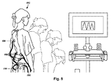
図8は、患者802が動的sEMG検査に伴う動きを行っている概略図である。図8では、動的sEMGモジュール106が、患者802が着用する(ベルトなどの)ストラップ804に結合されている。少なくともいくつかの実施形態では、測定電極806が患者802に取り付けられるとともに動的sEMGモジュール106に電気的に結合される。測定電極806は、患者の動きが制御されている最中に測定すべき筋群により決定される様々な脊髄レベルに配置される。例えば、測定電極806を患者802の背中に、脊柱に横方向に近接させて様々な脊髄レベルに取り付けて、患者が測定電極806を取り付けた場所の近くの筋肉を利用して動くときの活動電位の大きさ及びタイミングを測定することができる。少なくともいくつかの実施形態では、接地808を使用して患者802を動的sEMGモジュール106に結合することもできる。
FIG. 8 is a schematic view of a
図8では、患者802の背中に測定電極806が取り付けられており、これらが腰の屈伸運動中における選択した筋群に沿った活動電位の大きさ及びタイミングを測定する。少なくともいくつかの実施形態では、(各々が複数の異なる測定電極に電気的に結合された)複数の動的sEMGモジュール106を使用して、患者に複数の同時動的sEMG検査を行うことができる。少なくともいくつかの実施形態では、患者に複数の動的sEMG検査を行った場合、ハブ104に複数の結果を入力することができる。
In FIG. 8,
図9は、患者802に行った動的sEMG検査の例示的な表示902の一実施形態の概略図である。なお、動的sEMG検査の例示的な表示902は、他の多くの異なる方法で1又はそれ以上の視覚ディスプレイ204上に表示することができる。少なくともいくつかの実施形態では、例示的な表示902がハブ104上に、又はハブ104に電気的に結合された視覚ディスプレイ上に表示される。
FIG. 9 is a schematic diagram of one embodiment of an
少なくともいくつかの実施形態では、ROM検査と1又はそれ以上の動的sEMG検査を同時に行うことができる。図10は、ユーザ1002が患者1004にROM検査と動的sEMG検査を同時に行っている一実施形態の概略図である。傾斜計102(ROM検査)及び動的sEMGモジュール106の測定電極806(動的sEMG検査)を患者1004に結合して示している。少なくともいくつかの実施形態では、筋活動及び関節可動域を同時に測定することにより、患者の損傷の特質及び程度をさらに見抜くことができる。少なくともいくつかの実施形態では、ROM検査及び動的sEMG検査から得られるデータを単一のグラフィック表示でともに組み合わせて、患者が動いている最中の患者の筋反応のタイミング、対称性及び大きさを示すことができる。少なくともいくつかの実施形態では、ROM検査を動的sEMG検査と組み合わせることにより、読み取りの精度を上げるとともに、従来の検査から向上した再現性を伴う成果を挙げることもできる。
In at least some embodiments, a ROM test and one or more dynamic sEMG tests can be performed simultaneously. FIG. 10 is a schematic diagram of an embodiment in which a
少なくともいくつかの実施形態では、ROM検査から得られる動きの1又はそれ以上に関するデータを、図6に示す円グラフ結果602のような、ROMのための米国医師会(「AMA」)指針に従うグラフィックで構成することができる。現在では、ROMデータを収集して損傷評価を作成するための、AMA指針に基づく唯一既知の方法は、ROM検査を動的sEMGと別個に行うことである。ROM検査及び動的sEMG検査を同時に行って、AMA指針により規定された形式でROMデータを生成することにより、時間と金銭を節約することができる。少なくともいくつかの実施形態では、選択した回数の個々の動きの試行後に、AMA指針が許容する必要なばらつきの範囲内にROMデータがない場合、ROM検査が無効であり、これを再び実施できる旨をソフトウェアが自動的にユーザに通知することにより、さらなる時間と金銭が節約される可能性がある。
In at least some embodiments, data relating to one or more of the movements obtained from the ROM test is a graphic that conforms to the American Medical Association (“AMA”) guidelines for ROM, such as the
図11は、ROM検査と動的sEMG検査を同時に行った結果を示す例示的な視覚ディスプレイ1102の一実施形態の概略図である。図11では、視覚ディスプレイ1102の上半分に動的sEMGデータ1104をグラフ表示し、視覚ディスプレイ1102の下半分にROMデータ1106をグラフ表示している。動的sEMGデータ1104及びROMデータ1106は、患者1004が特定の動きを行っている最中に、選択した筋肉の対応する筋活動が視覚的にわかるように経時的に示される。少なくともいくつかの実施形態では、患者の筋反応のタイミング、対称性及び大きさを表示することができる。少なくともいくつかの実施形態では、このような情報が、患者損傷の特質及び程度に対応することができる。
FIG. 11 is a schematic diagram of one embodiment of an exemplary
少なくともいくつかの実施形態では、ビデオカメラ206などの1又はそれ以上のビデオカメラをさらに含めて、1又はそれ以上のROM検査及び動的sEMG検査を行っている1又はそれ以上の静止画像、又は好ましくはビデオを取り込むことにより、患者の損傷の特質及び程度をさらに見抜くことができる。図12は、ROM検査及び動的sEMG検査を受けている患者の1又はそれ以上の画像又はビデオを取り込むための例示的な検査構成の一実施形態の概略平面図である。図12では、ROM検査及び動的sEMG検査の実施中に患者が立つ地点を表す点1210及び1212を含むマット1208の周囲に3台のビデオカメラ1202、1204及び1206が配置されている。少なくともいくつかの実施形態では、ビデオカメラ1202が点1210及び1212上に立つ患者の真正面に位置し、ビデオカメラ1204が患者の真後ろに位置し、ビデオカメラ1206が患者の片側に位置する。
In at least some embodiments, further including one or more video cameras, such as
少なくともいくつかの実施形態では、取り込み画像又はビデオを追加して、1又はそれ以上の医師が再検討に利用できるようにすることができる。少なくともいくつかの実施形態では、ROM検査、動的sEMG検査の1又はそれ以上から得られるデータ及びビデオ(又は静止画像)をハブ104、1又はそれ以上のプロセッサ202、又は記憶装置に記憶して、1又はそれ以上の医師がスライダを使用して(前屈などの)患者の動きを再生し、正確な動き方を示す患者の身体のビデオとともに、患者が曲げた角度を正確に判断できるように構成することができる。さらに、その後同じ患者に同様の検査を行うことができる。このようにして、2又はそれ以上のデータセットを比較して、経時的な患者の進捗を追跡するためのデータを得ることができる。
In at least some embodiments, captured images or videos can be added to make them available for review by one or more physicians. In at least some embodiments, data and video (or still images) from one or more of ROM inspection, dynamic sEMG inspection are stored in the
少なくともいくつかの実施形態では、診断システム100が、患者に静的sEMG検査を行う(患者が所定の姿勢を保持している間に、選択した筋群に沿った活動電位を測定する)際にユーザが使用するためのスキャナ108を含む。静的sEMG検査では、スキャナ108の組を患者の皮膚に接触させて連続して配置している最中に一連の測定を行うことができることもある。図13は、診断システム100のスキャナ108の一実施形態の概略斜視図である。スキャナ108は各々、前端部1303上に配置された複数の測定電極1302を含む。少なくともいくつかの実施形態では、測定電極1302が、第1の測定電極の組1304及び第2の測定電極の組1306などの組になって配置される。スキャナ108はまた、前端部1303上に配置された接地1308も含む。
In at least some embodiments, the
少なくともいくつかの実施形態では、スキャナ108が、静的sEMG検査実施中にユーザが手で持つように構成及び設定される。少なくともいくつかの実施形態では、スキャナ108が各々、(ボタン、スイッチ、ノブなどの)1又はそれ以上の制御要素1310を含む。少なくともいくつかの実施形態では、スキャナ108のユーザが制御要素1310を使用して、静的sEMG検査中にキーパッド、キーボードなどを使用することなく、測定電極1304を患者の皮膚に接触させて連続して配置している間の進捗を制御することができる。少なくともいくつかの実施形態では、スキャナ108が、1又はそれ以上のLEDなどの1又はそれ以上のインジケータ1312を含み、これらが、静的sEMG検査の実施前、実施中、又は実施後に(バッテリレベル、オン/オフ、接続性などの)1又はそれ以上の表示をユーザに提供する。少なくともいくつかの実施形態では、スキャナ108が、ユーザ1602が静的sEMGを行っている間にスキャナ108を容易に把持できるようにする1又はそれ以上の把持部材(図示せず)を含む。例えば、スキャナ108は、静的sEMG検査の実施中にユーザ1602がスキャナ108を容易に保持できるように構成及び設定された1又はそれ以上の窪みを含むことができる。少なくともいくつかの実施形態では、スキャナ108が主電源スイッチを含み、これが一方の位置にあるときにスキャナ108の電源をオフに保つ。
In at least some embodiments, the
少なくともいくつかの実施形態では、測定電極1302の組が各々、第1の測定電極の組1304の測定電極1304a及び1304bなどの2つの電極を含む。少なくともいくつかの実施形態では、測定電極の組内の測定電極が、前端部1303において互いに水平に離間して配置される。少なくともいくつかの実施形態では、測定電極の組が互いに垂直に離間して配置される。接地1308は、前端部108上のあらゆる場所に配置することができる。少なくともいくつかの実施形態では、接地1308が、測定電極の組1304と1306の間に垂直に位置する。少なくともいくつかの実施形態では、接地1308が、測定電極の組1302内の個々の測定電極間に水平に位置する。
In at least some embodiments, each set of
少なくともいくつかの実施形態では、個々の測定電極1302の組が脊髄レベルに対応する。従って、スキャナ108上に配置される測定電極1302の組の数は、同時に測定できる脊髄レベルの数に一致することができる。少なくともいくつかの実施形態では、ユーザが、スキャナ108の測定電極1302を患者の背中に、患者の脊柱に横方向に近接させて所望のレベルに配置して活動電位を測定することができる。少なくともいくつかの実施形態では、図13に示すスキャナ108を使用して、患者に接触させたスキャナ108の配置ごとに、例えば頸部レベル2(「C2」)及び頸部レベル4(「C4」)などの2つの脊髄レベルを1度に測定することができる。
In at least some embodiments, each set of
スキャナ108上には、例えば、1組、2組、3組、4組、5組、6組、7組、8組、9組、10組、11組、12組、13組、14組、15組、16組、17組、18組、19組、20組、21組、22組、23組、24組、又はそれ以上の測定電極の組を含むあらゆる数の測定電極の組を配置することができる。同様に、スキャナ108上にさらなる測定電極の組を配置できることが理解されよう。
On the
少なくともいくつかの実施形態では、スキャナ108がハブ104と(及び任意にハブ104を介して1又はそれ以上のプロセッサ202と)通信する。少なくともいくつかの実施形態では、スキャナ108が無線である。スキャナ108が無線である場合、ユーザ及び患者は、ハブ104の直近に位置すること、又はつまづく可能性などの危険が生じ得る空間にわたって1又はそれ以上の導体を延ばすことにより潜在的危険性を生み出すことから解放される。この結果、(ユーザがモール、健康フェア、自動車ショーなどにいる場合)例えばスクリーニング時に無線スキャナ108を使用して、人々を検査センターに引き込む必要なく人混みの中に出て行って人々を検査することができる。少なくともいくつかの実施形態では、静的sEMG検査の結果を1又はそれ以上の視覚ディスプレイ204上にリアルタイムで示すことができる。少なくともいくつかの実施形態では、静的sEMGから得られたデータをハブ104に少なくとも30フィート送信することができる。
In at least some embodiments, the
少なくともいくつかの実施形態では、診断システム100が複数のスキャナ108の組を含むことにより、複数の患者に複数の静的sEMG検査を行う一方で、個々の静的sEMG検査から得られたデータをハブ104に(及び任意に1又はそれ以上のプロセッサ202に)入力して処理し、この結果を視覚ディスプレイ204などの1又はそれ以上のディスプレイに出力できるようになる。少なくともいくつかの実施形態では、単一の視覚ディスプレイ204上に複数の静的sEMG検査の結果を同時に表示することができる。例えば、視覚ディスプレイ204は、2又はそれ以上の患者の静的sEMG検査の結果を有する分割画面を含むことができる。
In at least some embodiments, the
測定電極1302は、例えば、金、ステンレス鋼、銀、塩化銀など、又はこれらの組み合わせを含む、患者の皮膚に接触させて配置するのに適した多くの異なる導電材料から形成することができる。接地1308もまた、例えば、金、ステンレス鋼、銀、塩化銀など、又はこれらの組み合わせを含む、患者の皮膚に接触させて配置するのに適した多くの異なる導電材料から形成することができる。少なくともいくつかの実施形態では、接地1308が、測定電極1302と同じ導電材料から形成される。
The
少なくともいくつかの実施形態では、スキャナ108を患者に接触させて配置したときの個々の接地1308と患者の間の接触を向上させるために、また測定電極の組1304及び1306が患者の背中などの患者の湾曲した部位に接触しているときの測定電極の組1304及び1306と患者との間の接触も向上させるために、スキャナ108の接地1308が伸縮自在である。
In at least some embodiments, to improve contact between the
図14Aは、スキャナ108の一方の接地1308が伸びた位置にあり、説明を明確にするためにスキャナ108の外部ケーシングの一部を除去した一実施形態の概略斜視図である。少なくともいくつかの実施形態では、スキャナ108内にバネ1402などのバネを配置し、これを使用して接地1308の伸縮性を実現する。スキャナ108内に(引張バネ、圧縮バネ、捩りバネ、コイルバネ、板バネ、リーフバネ、片持ちバネ、ひげゼンマイ、V字バネなど、又はこれらの組み合わせのような)いずれかの適当な種類のバネを実装して、接地1308の伸縮性を実現できることが理解されよう。少なくともいくつかの実施形態では、接地1308を伸縮自在にすることにより、接地1308に伸縮性がなければ、これが測定電極1302の組1304及び1306の少なくとも一方をそれぞれ患者の皮膚から離して浮き上がらせてしまうであろう湾曲部が患者の体に存在する場合でも、スキャナ108が体の曲線により良く適応でき、測定電極1302の第1及び第2の組1304及び1306がそれぞれ患者の皮膚に接触できるようになる。図14Bは、スキャナ108の一方の接地1308が引っ込んだ位置にあり、説明を明確にするためにスキャナ108の外部ケーシングの一部を除去した一実施形態の概略斜視図である。
FIG. 14A is a schematic perspective view of an embodiment in which one
少なくともいくつかの実施形態では、スキャナ108が測定する活動電位が1ミリボルト以下の場合がある。従って、接地ループ保護及びノイズ低減が重要事項になり得る。少なくともいくつかの実施形態では、個々の測定電極に同様の長さのワイヤリンクを使用することにより、ノイズがいくぶん低減される。
In at least some embodiments, the action potential measured by the
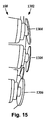
少なくともいくつかの実施形態では、測定電極1302の1又はそれ以上が、例えばスキャナ108を患者の体に押し付けたときの患者の体の曲線の変化に対応するように枢動可能である。図15は、スキャナ108の一方の測定電極1302の測定電極1304及び1306が各々互いに異なる角度で枢動する一実施形態の概略側面図である。少なくともいくつかの実施形態では、測定電極1302の1又はそれ以上が独立懸架装置を利用する。少なくともいくつかの実施形態では、測定電極1302の1又はそれ以上がボールソケットシステムを利用する。
In at least some embodiments, one or more of the
図16は、ユーザ1602がスキャナ108を使用して患者1604に静的sEMG検査を行っている一実施形態の概略図である。少なくともいくつかの実施形態では、スキャナ108の各々が、患者1604の脊柱に横方向に近接して脊柱の様々なレベルに配置される。例えば、図16では、スキャナ108が、患者の脊柱の頸部に横方向に近接して配置されている。上述したように、スキャナ108は、各々2組の測定電極の1302を含む。従って、図16では、スキャナ108を各々患者に接触させて配置している最中に2つの脊髄レベルで同時に測定を行うことができる。
FIG. 16 is a schematic diagram of one embodiment in which a
時間とともに、患者の異なる脊柱レベルにおいて一連の測定結果が取得される。筋肉の活動電位が測定され、対応するデータがハブ104(及び任意にハブ102を介して1又はそれ以上のプロセッサ202)に転送され、データが処理されて、この結果が1又はそれ以上の視覚ディスプレイ204などの1又はそれ以上のディスプレイ上に表示される。
Over time, a series of measurements are taken at different patient spine levels. The muscle action potential is measured and the corresponding data is transferred to the hub 104 (and optionally one or
少なくともいくつかの実施形態では、傾斜計108が1又はそれ以上のバッテリにより電力を供給される。少なくともいくつかの実施形態では、静的sEMG検査中、対応するソフトウェアが、スキャナ108を連続して配置する間の時間、スキャナ108の電源をオフにするための命令を実行してバッテリの残量を節約する。少なくともいくつかの実施形態では、静的sEMG検査中、スキャナ108が患者に接して配置されたときに、又は制御要素1301が関与したときに、対応するソフトウェアがスキャナ108の電源をオンにするための命令を実行する。少なくともいくつかの実施形態では、静的sEMG検査中、1又はそれ以上の制御要素1308が関与した後に、対応するソフトウェアがスキャナ108の電源をオフにする命令を実行する。
In at least some embodiments,
少なくともいくつかの実施形態では、スキャナ108が患者1604に接して正しく配置されたときに、ハブ104又は1又はそれ以上のプロセッサ202が、ユーザ1602に注意を促すためのプロンプトを提示する。いくつかの実施形態では、もう一方の視覚ディスプレイ204上に、位置情報及び静的sEMG検査を進めるための命令の1又はそれ以上が表示される。他の実施形態では、位置情報が1又はそれ以上の音声命令を通じて与えられる。
In at least some embodiments, the
図17は、患者に行った静的sEMG検査の2つの例示的な結果1702及び1704の一実施形態の概略図である。少なくともいくつかの実施形態では、2つの結果1702及び1704が1人の患者からのものである。少なくともいくつかの実施形態では、2つの結果1702及び1704が2人の異なる患者からのものである。少なくともいくつかの実施形態では、2つの結果1702及び1704の一方が患者からのものであり、他方の結果が、患者の結果と比較するための「理想的な」結果などのモデル結果である。
FIG. 17 is a schematic diagram of one embodiment of two
上述したように、スキャナ108は、様々な数の測定電極の組を含むことができる。少なくともいくつかの実施形態では、3組以上の測定電極を使用することができる。また、少なくともいくつかの実施形態では、追加の接地を使用することもできる。いくつかの実施形態では、測定電極が、スキャナ108などのハンドヘルド型スキャナに結合される。少なくともいくつかの実施形態では、測定電極が、自立型スキャナ、又は壁などの1又はそれ以上の平面に取り付けたスキャナに結合される。
As described above, the
図18は、24組の測定電極1803を有する静的sEMGスキャナ1802の一実施形態の概略斜視図である。静的sEMGスキャナ1802は、基部1804と、1又はそれ以上の取り付けボード1810に取り付けられた測定電極の組1803の2つの支柱1806及び1808と、少なくとも1つの接地1812とを含む。個々の支柱1806及び1808は、組1814などの複数組の測定電極1803を含む。少なくともいくつかの実施形態では、静的sEMGスキャナ1802がハブ104に結合される。
FIG. 18 is a schematic perspective view of one embodiment of a
少なくともいくつかの実施形態では、測定電極1803が伸縮自在である。従って、少なくともいくつかの実施形態では、患者が測定電極1803に接触したときに、測定電極1803がある程度の距離引っ込む。少なくともいくつかの実施形態では、静的sEMGスキャナ1802を壁に取り付ける場合、静的sEMGスキャナ1802が、患者が測定電極1803に接触したときの測定電極1803の引っ込みに対応するのに十分なだけ壁から離れて配置される。少なくともいくつかの実施形態では、静的sEMGスキャナ1802が、患者が測定電極1803の1又はそれ以上に接触している(及び結果的に引っ込んでいる)ときに、静的sEMGスキャナ1802を取り付けた壁に測定電極1803の1又はそれ以上が接触するのを防ぐための1又はそれ以上のスペーサ棒1816を含む。少なくともいくつかの実施形態では、測定電極1803を、静的sEMG検査中の患者の皮膚との接触を向上させるように調整することができる。少なくともいくつかの実施形態では、測定電極1803の2つの支柱1806及び1808を移動可能に取り付けることにより、これらを水平に動かして接近させたり、又は互いに離したりして、測定電極1803が様々な脊柱の幅を持つ患者とより良好に接触するようにすることができる。少なくともいくつかの実施形態では、支柱1806及び1808の各々の床からの高さを上下させて、測定電極1803が異なる身長の患者とより良好に接触するようにすることができる。
In at least some embodiments, the
少なくともいくつかの実施形態では、測定電極1803の個々の測定電極1803の組の間に旋回軸が延びて患者との接触を向上させる。図18では、測定電極1803の個々の測定電極の組の間に垂直方向に延びる2つの棒1818及び1820として旋回軸を示している。少なくともいくつかの実施形態では、測定電極1803をゴムなどの柔軟な物質上に取り付けることにより、個々の測定電極1803の組が左/右に旋回しやすくなる。
In at least some embodiments, a pivot axis extends between
少なくともいくつかの実施形態では、付属のソフトウェアが、患者の皮膚に接している測定電極1803と、患者の皮膚に接していない測定電極1803とを区別する。少なくともいくつかの実施形態では、このソフトウェアが、測定電極1803の1又はそれ以上からの活動電位の測定値がいつゼロ(患者と非接触)であるかを検出することができる。少なくともいくつかの実施形態では、ユーザが、2つの支柱1806及び1808の患者と接触する最上部及び最下部の測定電極1803を、測定電極1803を示す表示から選択することができる。例えば、(特に背の低い患者に静的sEMG検査を行うような場合)ユーザは、取り付けボード1810の各々の上位2つの測定電極1803の組を無視すべきであることを選択することができる。別の例として、ユーザは、最上部の測定電極の組が患者の頸部レベル4(「C4」)に設定されるように、及び最下部の測定電極の組が患者の腰部レベル1(「L1」)に設定されるように選択して、下位6組の測定電極を患者と接触しないようにすることができる。
In at least some embodiments, the accompanying software distinguishes between
図19は、静的sEMGスキャナ1802の測定電極1803の1つの一実施形態の概略側面図である。測定電極1803は、導電部材1906に取り付けられた湾曲した接触面1904を含み、この導電部材1906が、さらに取り付けボード1810に取り付けられる。少なくともいくつかの実施形態では、導電部材1906がバネ1908に結合される。少なくともいくつかの実施形態では、バネ1908により、患者が測定電極1803の接触面1904に接触したときに測定電極1803が容易に引っ込むようになる。1つの特定の実施形態では、バネ1908が、測定電極1803が最大12インチ(約30cm)引っ込むことができるように構成及び設定される。
FIG. 19 is a schematic side view of one embodiment of a
図20は、第1の位置2004、及びこの第1の位置2004から水平に旋回した第2の位置2006にある4つの測定電極1803を示す一実施形態の概略図である。少なくともいくつかの実施形態では、旋回可能な測定電極により、患者が測定電極1803と接触しているときの測定電極1803と患者の間の接触を向上させることができる。少なくともいくつかの実施形態では、測定電極1803が、棒1818及び1820の一方などの旋回軸の周りで旋回する。いくつかの実施形態では、測定電極1803が水平に旋回することができる。他の実施形態では、測定電極1803が垂直に旋回することができる。他の実施形態では、測定電極1803が、横軸又は縦軸以外の他の軸に沿って旋回することができる。他の実施形態では、患者が接触面1904に接触しているときに、測定電極が必要に応じて容易に曲がるようにして接触を向上させるゴムなどの柔軟な材料を使用して測定電極の非接触面を形成することにより患者との接触が改善される。
FIG. 20 is a schematic diagram of an embodiment showing four
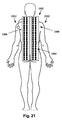
図21は、静的sEMGスキャナ1802を人物像2102の背中に位置合わせした一実施形態の概略後面図である。図21では、測定電極1803の2つの支柱1806及び8108、及び接地1812が人物像2102の背中に接触している。少なくともいくつかの実施形態では、測定電極803の2つの支柱1806及び1808が、測定電極1803が人物像2102の背中に、脊柱に横方向に近接して接触するように構成及び設定される。
FIG. 21 is a schematic rear view of an embodiment in which the
少なくともいくつかの実施形態では、ビデオカメラ206などの1又はそれ以上のビデオカメラをさらに含めて、静的sEMG検査を行っている1又はそれ以上の画像又はビデオを取り込むことにより、患者の損傷の特質及び程度をさらに見抜くことができる。図22は、静的sEMG検査を受けている患者の画像を生成するための例示的な検査構成の一実施形態の概略平面図である。図22では、静的sEMG検査の実施中に患者が立つ場所を表す領域2210及び2212を含むマット2208の周囲に3台のビデオカメラ2202、2204及び2206が位置する。少なくともいくつかの実施形態では、ビデオカメラ2202が領域2210及び2212上に立つ患者の真正面に位置し、ビデオカメラ2204が患者の真後ろに位置し、ビデオカメラ2206が患者の片側に位置する。少なくともいくつかの実施形態では、患者が静的sEMG検査を受けている間、患者の1又はそれ以上のビデオ又は1又はそれ以上の静止画の少なくとも1つを生成することができる。
In at least some embodiments, one or more video cameras, such as
少なくともいくつかの実施形態では、1又はそれ以上の異なる角度からのビデオ(又は1又はそれ以上の取り込み画像)を追加して、1又はそれ以上の医師が再検討に利用できるようにすることができる。少なくともいくつかの実施形態では、静的sEMG検査から得られるデータ及び1又はそれ以上の取り込みビデオ(又は静止画像)を1又はそれ以上のプロセッサ202に記憶して、1又はそれ以上の医師が静的sEMG検査のデータを収集したときの患者の位置を正確に把握できるようにすることができる。さらに、患者の進捗を経時的に追跡するために、その後同じ患者に同様の検査を行うことができる。
In at least some embodiments, video (or one or more captured images) from one or more different angles may be added to be available for review by one or more physicians. it can. In at least some embodiments, data obtained from static sEMG examinations and one or more captured videos (or still images) are stored in one or
上記明細書、実例及びデータは、本発明の構成の製造法と使用法を説明したものである。本発明の思想及び範囲から逸脱することなく本発明の多くの実施形態を構成することができるので、本発明は、以下に添付する特許請求の範囲にも属する。 The above specification, examples and data illustrate how to make and use the composition of the invention. Since many embodiments of the invention can be made without departing from the spirit and scope of the invention, the invention also resides in the claims hereinafter appended.
100 診断システム
102 傾斜計
104 ハブ
106 動的sEMGモジュール
108 スキャナ
100
Claims (10)
メインユニット及び補助ユニットを含み、前記メインユニットが前記関節近くに位置し、前記補助ユニットが前記患者の関節に沿って動く身体部位に沿って位置するようにして一端が患者の関節に沿って動く患者の身体部位の2つの端部近くに配置されるように構成及び設定されるとともに、患者の制御された前記関節の動作中の前記メインユニットと前記補助ユニットの間に形成される角度を測定するように構成及び設定された1組のハンドヘルド型傾斜計と、
動的表面筋電計(「sEMG」)モジュールと、前記動的sEMGモジュールに電気的に結合された少なくとも1組の測定電極と、
を備え、前記測定電極が、前記関節に沿って動く前記身体部位に沿って前記患者の外部に、前記患者の脊柱の複数のレベルに横方向に近接して結合するように構成及び設定されるとともに、前記患者の制御された前記関節の動作中の前記測定電極の真下にある患者筋群に沿った活動電位を測定し、該測定した活動電位を前記動的sEMGモジュールへ送信するように構成及び設定され、
前記傾斜計及び前記動的sEMGモジュールから収集した、前記患者の制御された前記関節の動作中の前記データを受信し、該受信データを処理して少なくとも1つの表示可能な画像に変えるように構成及び設定されたハブと、
前記処理したデータを前記ハブから受信して表示するように構成及び設定された、前記ハブに電気的に結合された視覚ディスプレイと、
をさらに備えることを特徴とする診断システム。 A soft tissue injury diagnostic system for diagnosing soft tissue damage in a patient's body,
A main unit and an auxiliary unit, wherein one end moves along the patient's joint so that the main unit is located near the joint and the auxiliary unit is located along a body part that moves along the patient's joint Constructed and set to be positioned near two ends of the patient's body part and measures the angle formed between the main unit and the auxiliary unit during operation of the patient's controlled joint A set of handheld inclinometers configured and configured to:
A dynamic surface electromyograph (“sEMG”) module and at least one set of measurement electrodes electrically coupled to the dynamic sEMG module;
And wherein the measurement electrode is configured and set to couple laterally close to a plurality of levels of the patient's spinal column, external to the patient along the body part moving along the joint And measuring an action potential along a patient muscle group directly under the measurement electrode during operation of the patient's controlled joint, and transmitting the measured action potential to the dynamic sEMG module. And set
Configured to receive the data during operation of the patient's controlled joints collected from the inclinometer and the dynamic sEMG module and process the received data into at least one displayable image. And a configured hub,
A visual display electrically coupled to the hub configured and configured to receive and display the processed data from the hub;
A diagnostic system further comprising:
ことを特徴とする請求項1に記載の診断システム。 The data collected from the inclinometer and the data collected from the dynamic sEMG module are collected simultaneously;
The diagnostic system according to claim 1.
ことを特徴とする請求項1に記載の診断システム。 And further comprising at least one processor coupled to the hub, wherein the at least one processor provides additional processing power to process the received data into at least one displayable image. To be
The diagnostic system according to claim 1.
ことを特徴とする請求項1に記載の診断システム。 The inclinometers each include an accelerometer;
The diagnostic system according to claim 1.
ことを特徴とする請求項1に記載の診断システム。 Each of the inclinometers is disk-shaped and has a flat bottom surface extending tangentially from the bottom of the inclinometer, and the flat bottom surfaces of the individual inclinometers are spaced apart from each other by extending downward from the flat bottom surface. And at least one of the two feet can be adjusted along the axis of the flat bottom so as to adjust the amount of space between the two feet.
The diagnostic system according to claim 1.
ことを特徴とする請求項1に記載の診断システム。 Each of the inclinometers includes a plurality of light emitting diodes positioned along the inclinometer for indicating degree markings;
The diagnostic system according to claim 1.
ことを特徴とする請求項1に記載の診断システム。 And at least one image capture device coupled to the hub, the at least one image capture device having at least one of a video or at least one still image of the patient performing a controlled movement of the joint. Configured and configured to capture,
The diagnostic system according to claim 1.
患者の選択した筋群に沿った活動電位を測定するための静的表面筋電図検査(「sEMG」)スキャナであって、前記患者の脊柱に横方向に近接して患者の皮膚に接して配置されるように構成及び設定された、前記静的sEMGスキャナから延びる少なくとも2組の測定電極と、前記少なくとも2組の測定電極から離れて患者の皮膚に接して配置されるように構成及び設定された少なくとも1つの接地とを備える静的sEMGスキャナと、
メインユニット及び補助ユニットを含み、前記メインユニットが前記関節近くに位置し、前記補助ユニットが前記患者の関節に沿って動く身体部位に沿って位置するようにして一端が患者の関節に沿って動く患者の身体部位の2つの端部近くに配置されるように構成及び設定されるとともに、患者の制御された前記関節の動作中の前記メインユニットと前記補助ユニットの間に形成される角度を測定するように構成及び設定された1組のハンドヘルド型傾斜計と、
動的表面筋電計(「sEMG」)モジュールと、前記動的sEMGモジュールに電気的に結合された少なくとも1組の測定電極と、
を備え、前記測定電極が、前記関節に沿って動く前記身体部位に沿って前記患者の外部に、前記患者の脊柱の複数のレベルに横方向に近接して結合するように構成及び設定されるとともに、前記患者の制御された前記関節の動作中の前記測定電極の真下にある患者筋群に沿った活動電位を測定し、該測定した活動電位を前記動的sEMGモジュールへ送信するように構成及び設定され、
前記傾斜計及び前記動的sEMGモジュールから収集した、前記患者の制御された前記関節の動作中の前記データを受信し、該受信データを処理して少なくとも1つの表示可能な画像に変えるように構成及び設定されたハブと、
前記処理したデータを前記ハブから受信して表示するように構成及び設定された、前記ハブに電気的に結合された視覚ディスプレイと、
をさらに備えることを特徴とする診断システム。 A soft tissue injury diagnostic system for diagnosing soft tissue damage in a patient's body,
A static surface electromyography ("sEMG") scanner for measuring action potentials along a selected muscle group of a patient, in contact with the patient's skin laterally adjacent to the patient's spinal column At least two sets of measurement electrodes extending and configured from the static sEMG scanner configured and set to be positioned, and configured and set to be positioned in contact with the patient's skin away from the at least two sets of measurement electrodes A static sEMG scanner comprising at least one ground connected ;
A main unit and an auxiliary unit, wherein one end moves along the patient's joint so that the main unit is located near the joint and the auxiliary unit is located along a body part that moves along the patient's joint Constructed and set to be positioned near two ends of the patient's body part and measures the angle formed between the main unit and the auxiliary unit during operation of the patient's controlled joint A set of handheld inclinometers configured and configured to:
A dynamic surface electromyograph (“sEMG”) module and at least one set of measurement electrodes electrically coupled to the dynamic sEMG module;
And wherein the measurement electrode is configured and set to couple laterally close to a plurality of levels of the patient's spinal column, external to the patient along the body part moving along the joint And measuring an action potential along a patient muscle group directly under the measurement electrode during operation of the patient's controlled joint, and transmitting the measured action potential to the dynamic sEMG module. And set
Configured to receive the data during operation of the patient's controlled joints collected from the inclinometer and the dynamic sEMG module and process the received data into at least one displayable image. And a configured hub,
A visual display electrically coupled to the hub configured and configured to receive and display the processed data from the hub;
A diagnostic system further comprising:
患者の身体部位の一端における患者の制御された関節の動作中の、前記ROM装置の前記関節の近くに位置するメインユニットと、前記患者の関節に沿って動く身体部位に沿って位置する補助ユニットとの間で測定される角度を処理するステップと、
前記患者の制御された前記関節の動作中の、前記身体部位に沿った前記患者の複数の脊柱レベルに横方向に近接して患者の皮膚に結合された前記動的sEMG装置の測定電極の真下にある患者筋群に沿って測定される活動電位を処理するステップと、
前記処理したデータを視覚ディスプレイ上に表示するステップと、
を含む動作を実行できるようになる、
ことを特徴とするコンピュータ可読媒体。 A computer-readable medium having processor-executable instructions for reading data from a range of motion ("ROM") device and a dynamic surface electromyography ("sEMG") device, the processor-executable instructions When installed above, the processor executable instructions cause the device to
A main unit located near the joint of the ROM device during operation of the patient's controlled joint at one end of the patient's body part, and an auxiliary unit located along the body part moving along the patient's joint Processing the angle measured between and
Directly below the measurement electrode of the dynamic sEMG device coupled to the patient's skin in lateral proximity to the patient's plurality of spinal levels along the body part during operation of the patient's controlled joint Processing action potentials measured along the patient muscle group at
Displaying the processed data on a visual display;
Can perform actions including
A computer-readable medium characterized by the above.
前記ハブと通信するプロセッサと、
を備え、前記プロセッサが、
患者の身体部位の一端における患者の制御された関節の動作中の、前記ROM装置の前記関節の近くに位置するメインユニットと、前記患者の関節に沿って動く身体部位に沿って位置する補助ユニットとの間で測定される角度を処理するステップと、
前記患者の制御された前記関節の動作中の、前記身体部位に沿った前記患者の複数の脊柱レベルに横方向に近接して患者の皮膚に結合された前記動的sEMG装置の測定電極の真下にある患者筋群に沿って測定される活動電位を処理するステップと、
前記処理したデータを視覚ディスプレイ上に表示するステップと、
を含む動作を可能にするプロセッサ可読命令を実行する、
ことを特徴とする軟部組織損傷診断装置。 A range of motion (“ROM”) device and a dynamic surface electromyography (“sEMG”) device coupled to the hub;
A processor in communication with the hub;
The processor comprises:
A main unit located near the joint of the ROM device during operation of the patient's controlled joint at one end of the patient's body part, and an auxiliary unit located along the body part moving along the patient's joint Processing the angle measured between and
Directly below the measurement electrode of the dynamic sEMG device coupled to the patient's skin in lateral proximity to the patient's plurality of spinal levels along the body part during operation of the patient's controlled joint Processing action potentials measured along the patient muscle group at
Displaying the processed data on a visual display;
Executing processor readable instructions that enable operations comprising:
An apparatus for diagnosing soft tissue damage.
Applications Claiming Priority (3)
| Application Number | Priority Date | Filing Date | Title |
|---|---|---|---|
| US5816008P | 2008-06-02 | 2008-06-02 | |
| US61/058,160 | 2008-06-02 | ||
| PCT/US2009/045828 WO2009149008A2 (en) | 2008-06-02 | 2009-06-01 | Systems and methods for performing surface electromyography and range-of-motion tests |
Related Child Applications (1)
| Application Number | Title | Priority Date | Filing Date |
|---|---|---|---|
| JP2013231408A Division JP2014061413A (en) | 2008-06-02 | 2013-11-07 | System and method for performing surface electromyogram and joint movable region examination |
Publications (3)
| Publication Number | Publication Date |
|---|---|
| JP2011521768A JP2011521768A (en) | 2011-07-28 |
| JP2011521768A5 JP2011521768A5 (en) | 2012-05-31 |
| JP5453404B2 true JP5453404B2 (en) | 2014-03-26 |
Family
ID=41380661
Family Applications (2)
| Application Number | Title | Priority Date | Filing Date |
|---|---|---|---|
| JP2011512562A Active JP5453404B2 (en) | 2008-06-02 | 2009-06-01 | System for performing surface electromyography and joint range of motion tests |
| JP2013231408A Pending JP2014061413A (en) | 2008-06-02 | 2013-11-07 | System and method for performing surface electromyogram and joint movable region examination |
Family Applications After (1)
| Application Number | Title | Priority Date | Filing Date |
|---|---|---|---|
| JP2013231408A Pending JP2014061413A (en) | 2008-06-02 | 2013-11-07 | System and method for performing surface electromyogram and joint movable region examination |
Country Status (9)
| Country | Link |
|---|---|
| US (1) | US9808172B2 (en) |
| EP (2) | EP2296545B1 (en) |
| JP (2) | JP5453404B2 (en) |
| KR (2) | KR101324868B1 (en) |
| CN (1) | CN102046079B (en) |
| AU (1) | AU2009256441B2 (en) |
| DK (1) | DK2296545T3 (en) |
| HK (1) | HK1157171A1 (en) |
| WO (1) | WO2009149008A2 (en) |
Families Citing this family (24)
| Publication number | Priority date | Publication date | Assignee | Title |
|---|---|---|---|---|
| US8117047B1 (en) | 2007-04-16 | 2012-02-14 | Insight Diagnostics Inc. | Healthcare provider organization |
| CA2706356C (en) | 2008-02-20 | 2017-03-28 | Mako Surgical Corp. | Implant planning using corrected captured joint motion information |
| US11557073B2 (en) | 2008-06-02 | 2023-01-17 | Precision Biometrics, Inc. | System for generating medical diagnostic images |
| EP2241246A1 (en) * | 2009-04-14 | 2010-10-20 | Koninklijke Philips Electronics N.V. | Using muscle tension sensing to locate an analyte measurement site on the skin |
| WO2012040390A2 (en) | 2010-09-21 | 2012-03-29 | Somaxis Incorporated | Methods for assessing and optimizing muscular performance |
| US8752427B2 (en) | 2010-11-05 | 2014-06-17 | Med-Tek Llc | Functional capacity evaluator |
| DE102010051519A1 (en) * | 2010-11-15 | 2012-05-16 | Zebris Medical Gmbh | An imaging device for the large-area imaging of a body portion |
| US9936891B2 (en) | 2011-06-08 | 2018-04-10 | Precision Biometrics, Inc. | Systems and methods for providing biometric related to performance of a physical movement |
| KR101884434B1 (en) * | 2011-12-02 | 2018-08-02 | (주)아모레퍼시픽 | Skin external composition containing Pedicularis verticillata Linne var.hallaisanensis extract |
| US20140191880A1 (en) * | 2013-01-10 | 2014-07-10 | Covidien Lp | System, method, and software for ambulatory patient monitoring |
| AU2014235339B2 (en) | 2013-03-15 | 2018-09-20 | Biogen Ma Inc. | Assessment of labeled probes in a subject |
| CN103222866B (en) * | 2013-04-09 | 2014-12-17 | 北京航空航天大学 | Measuring device for comfortable operation range of human arm |
| US20150126893A1 (en) * | 2013-11-01 | 2015-05-07 | Maryrose Cusimano Reaston | Method For Determining If Surgically-Implanted Hardware Should Be Removed |
| KR101602704B1 (en) * | 2014-08-07 | 2016-03-11 | 한국 한의학 연구원 | APPARATUS AND METHOD FOR DECIDING OF spinal tuberculosis |
| US11064936B2 (en) | 2014-09-04 | 2021-07-20 | Active4D, Inc. | Shoulder monitoring and treatment system |
| JP6325482B2 (en) * | 2015-04-06 | 2018-05-16 | バンドー化学株式会社 | Capacitance type sensor sheet and sensor device |
| US10206639B2 (en) | 2015-09-25 | 2019-02-19 | Biogen Ma Inc. | Wearable medical detector |
| WO2017189748A1 (en) * | 2016-04-29 | 2017-11-02 | Freer Logic, Inc. | Non-contact body and head-based monitoring of brain electrical activity |
| CN107518895B (en) * | 2016-06-22 | 2020-07-17 | 宁波工程学院 | Same muscle detection method for rehabilitation training |
| WO2018098221A1 (en) * | 2016-11-22 | 2018-05-31 | Biogen Ma Inc. | Medical diagnostic and treatment systems and their methods of use |
| RU2700261C1 (en) * | 2018-03-14 | 2019-09-13 | Федеральное Государственное бюджетное образовательное учреждение высшего образования Дагестанский государственный медицинский университет Министерства здравоохранения Российской Федерации Даггосмедуниверситет | Method for differential diagnosis of muscular hypotension of central and primary-muscular genesis in infants |
| CN109394226A (en) * | 2018-09-05 | 2019-03-01 | 李松波 | A kind of human body flexibility quality evaluates and tests training equipment and evaluating method |
| US20220125332A1 (en) * | 2020-10-26 | 2022-04-28 | Nazmi Peyman | Miniature wearable capnography device |
| CN113627401A (en) * | 2021-10-12 | 2021-11-09 | 四川大学 | Myoelectric gesture recognition method of feature pyramid network fused with double-attention machine system |
Family Cites Families (33)
| Publication number | Priority date | Publication date | Assignee | Title |
|---|---|---|---|---|
| US4320767A (en) * | 1980-04-07 | 1982-03-23 | Villa Real Antony Euclid C | Pocket-size electronic cuffless blood pressure and pulse rate calculator with optional temperature indicator, timer and memory |
| US4492029A (en) * | 1982-05-06 | 1985-01-08 | Jeco Company Limited | Inclinometer |
| US4664130A (en) * | 1985-06-06 | 1987-05-12 | Diagnospine Research Inc. | Method and equipment for the detection of mechanical injuries in the lumbar spine of a patient |
| US5215100A (en) * | 1991-04-29 | 1993-06-01 | Occupational Preventive Diagnostic, Inc. | Nerve condition monitoring system and electrode supporting structure |
| US5369416A (en) * | 1992-06-17 | 1994-11-29 | Indikon Company, Inc. | Multi-color bargraph |
| US5299572A (en) | 1992-10-30 | 1994-04-05 | University Of British Columbia | Biological electrode array |
| US5588444A (en) | 1992-11-19 | 1996-12-31 | Petragallo; Michael R. | Human range of motion measurement system |
| US5459676A (en) * | 1993-12-01 | 1995-10-17 | Livingston; J. Tracy | Self contained dual inclinometer system |
| US5462065A (en) * | 1994-08-17 | 1995-10-31 | Cusimano; Maryrose | Integrated movement analyziing system |
| US5513651A (en) | 1994-08-17 | 1996-05-07 | Cusimano; Maryrose | Integrated movement analyzing system |
| US6004312A (en) | 1997-04-15 | 1999-12-21 | Paraspinal Diagnostic Corporation | Computerized EMG diagnostic system |
| US6047202A (en) * | 1997-04-15 | 2000-04-04 | Paraspinal Diagnostic Corporation | EMG electrode |
| US6745062B1 (en) * | 1998-10-05 | 2004-06-01 | Advanced Imaging Systems, Inc. | Emg electrode apparatus and positioning system |
| US6364849B1 (en) | 1999-05-03 | 2002-04-02 | Access Wellness And Physical Therapy | Soft tissue diagnostic apparatus and method |
| US20020133094A1 (en) | 1999-05-03 | 2002-09-19 | Access Wellness And Physical Therapy | Soft tissue diagnostic apparatus and method |
| US7470236B1 (en) | 1999-11-24 | 2008-12-30 | Nuvasive, Inc. | Electromyography system |
| US7027633B2 (en) | 2000-11-30 | 2006-04-11 | Foran David J | Collaborative diagnostic systems |
| US6678549B2 (en) | 2001-03-26 | 2004-01-13 | Cusimano Maryrose | Combined physiological monitoring system |
| US6823212B2 (en) * | 2001-06-13 | 2004-11-23 | The Procter & Gamble Company | Method and apparatus for measuring properties of a target surface |
| EP2481338A3 (en) * | 2001-09-25 | 2012-09-05 | Nuvasive, Inc. | System for performing surgical procedures and assessments |
| US8059815B2 (en) | 2001-12-13 | 2011-11-15 | Digimarc Corporation | Transforming data files into logical storage units for auxiliary data through reversible watermarks |
| JP2004187736A (en) | 2002-12-06 | 2004-07-08 | Eucalyptus:Kk | Body surface electrocardiograph |
| WO2005006956A2 (en) | 2003-07-09 | 2005-01-27 | Medical Technologies Unlimited, Inc. | Comprehensive neuromuscular profiler |
| JP4432420B2 (en) | 2003-09-17 | 2010-03-17 | 横浜ゴム株式会社 | Work comfort level evaluation apparatus and work comfort level evaluation method |
| AU2003283811A1 (en) | 2003-10-24 | 2005-05-11 | Humanitas Mirasole S.P.A. | A motor function test system |
| US8170637B2 (en) * | 2008-05-06 | 2012-05-01 | Neurosky, Inc. | Dry electrode device and method of assembly |
| US20060052720A1 (en) | 2004-09-03 | 2006-03-09 | Ross David B | Evaluation of pain in humans |
| US8032210B2 (en) | 2005-10-06 | 2011-10-04 | Spinematrix, Inc. | EMG diagnostic system and method |
| JP2007209608A (en) | 2006-02-10 | 2007-08-23 | Omron Healthcare Co Ltd | Portable electrocardiograph |
| US20090005709A1 (en) * | 2007-06-27 | 2009-01-01 | Gagne Raoul J | Range of motion measurement device |
| WO2011047200A2 (en) | 2009-10-14 | 2011-04-21 | Great Connection, Inc. | Systems and methods for converting and delivering medical images to mobile devices and remote communications systems |
| US20120095779A1 (en) | 2010-10-13 | 2012-04-19 | Wengrovitz Michael S | Method and apparatus for providing location-based data and services in healthcare environments |
| US9147178B2 (en) | 2012-01-16 | 2015-09-29 | International Business Machines Corporation | De-identification in visual media data |
-
2009
- 2009-06-01 EP EP09759169.7A patent/EP2296545B1/en active Active
- 2009-06-01 WO PCT/US2009/045828 patent/WO2009149008A2/en active Application Filing
- 2009-06-01 EP EP13181241.4A patent/EP2666410B1/en active Active
- 2009-06-01 KR KR1020107029868A patent/KR101324868B1/en active IP Right Grant
- 2009-06-01 JP JP2011512562A patent/JP5453404B2/en active Active
- 2009-06-01 AU AU2009256441A patent/AU2009256441B2/en active Active
- 2009-06-01 US US12/455,385 patent/US9808172B2/en active Active
- 2009-06-01 DK DK09759169.7T patent/DK2296545T3/en active
- 2009-06-01 CN CN200980120464.3A patent/CN102046079B/en not_active Expired - Fee Related
- 2009-06-01 KR KR1020127027138A patent/KR101508822B1/en active IP Right Grant
-
2011
- 2011-11-01 HK HK11111734.5A patent/HK1157171A1/en not_active IP Right Cessation
-
2013
- 2013-11-07 JP JP2013231408A patent/JP2014061413A/en active Pending
Also Published As
| Publication number | Publication date |
|---|---|
| HK1157171A1 (en) | 2012-06-29 |
| WO2009149008A2 (en) | 2009-12-10 |
| EP2296545A2 (en) | 2011-03-23 |
| EP2666410B1 (en) | 2016-08-10 |
| CN102046079A (en) | 2011-05-04 |
| KR20110025935A (en) | 2011-03-14 |
| EP2296545B1 (en) | 2014-12-03 |
| KR20120121929A (en) | 2012-11-06 |
| WO2009149008A3 (en) | 2010-03-04 |
| EP2666410A1 (en) | 2013-11-27 |
| JP2011521768A (en) | 2011-07-28 |
| EP2296545A4 (en) | 2012-11-14 |
| US9808172B2 (en) | 2017-11-07 |
| AU2009256441A1 (en) | 2009-12-10 |
| US20090299210A1 (en) | 2009-12-03 |
| AU2009256441B2 (en) | 2013-06-13 |
| JP2014061413A (en) | 2014-04-10 |
| KR101324868B1 (en) | 2013-11-01 |
| CN102046079B (en) | 2014-08-06 |
| KR101508822B1 (en) | 2015-04-07 |
| DK2296545T3 (en) | 2015-02-02 |
Similar Documents
| Publication | Publication Date | Title |
|---|---|---|
| JP5453404B2 (en) | System for performing surface electromyography and joint range of motion tests | |
| JP4529884B2 (en) | Body fat measuring device and upper limb unit | |
| JP5038620B2 (en) | Motor function testing device | |
| JP2008539897A (en) | Method for real-time mechanical imaging of the prostate and dual array transducer probe | |
| CA2288720A1 (en) | Muscle function assessment apparatus and method | |
| CN112089442B (en) | Muscle training method and system for providing visual feedback by utilizing ultrasonic imaging | |
| KR20100119363A (en) | Unified measuring apparatus for physical activity promotion system | |
| Hong et al. | Measurement of covered curvature based on a tape of integrated accelerometers | |
| JP2019063091A (en) | Maintenance system, maintenance method, and maintenance program | |
| US11557073B2 (en) | System for generating medical diagnostic images | |
| KR102234845B1 (en) | Contact messages within personalized medical diagnostic images | |
| JP6062889B2 (en) | Muscle contraction exercise support system | |
| AU2013203331A1 (en) | Systems and methods for performing surface electromyography and range-of-motion tests | |
| JP2006034809A (en) | Stretch reflex measuring apparatus | |
| CN213309660U (en) | Physical examination instrument | |
| KR101945339B1 (en) | Fitness measuring system | |
| EP3658023B1 (en) | Method for assessing balance | |
| RU76561U1 (en) | DEVICE FOR EVALUATION AND DIAGNOSTICS OF PSYCHOPHYSIOLOGICAL STATE OF HUMAN | |
| Lewis et al. | PLASTIC OPTICAL FIBRE BASED SENSORS FOR MONITORING PHYSIOLOGICAL PARAMETERS IN CLINICAL ENVIRONMENTS | |
| WO2022042778A2 (en) | Ultrasound elastography system for use as a diagnostic support tool for persons with muscle spasticity, and corresponding operating method | |
| AU718995B2 (en) | Muscle function assessment apparatus and method | |
| CN113995399A (en) | Joint state testing device | |
| GR1009368B (en) | Device for evaluating via sound and visual feedback the exercising of the lumbopelvic region | |
| AU1639899A (en) | Muscle functiion assessment apparatus and method |
Legal Events
| Date | Code | Title | Description |
|---|---|---|---|
| A521 | Request for written amendment filed |
Free format text: JAPANESE INTERMEDIATE CODE: A523 Effective date: 20120405 |
|
| A621 | Written request for application examination |
Free format text: JAPANESE INTERMEDIATE CODE: A621 Effective date: 20120405 |
|
| A977 | Report on retrieval |
Free format text: JAPANESE INTERMEDIATE CODE: A971007 Effective date: 20130729 |
|
| A131 | Notification of reasons for refusal |
Free format text: JAPANESE INTERMEDIATE CODE: A131 Effective date: 20130807 |
|
| A521 | Request for written amendment filed |
Free format text: JAPANESE INTERMEDIATE CODE: A523 Effective date: 20131107 |
|
| TRDD | Decision of grant or rejection written | ||
| A01 | Written decision to grant a patent or to grant a registration (utility model) |
Free format text: JAPANESE INTERMEDIATE CODE: A01 Effective date: 20131202 |
|
| A61 | First payment of annual fees (during grant procedure) |
Free format text: JAPANESE INTERMEDIATE CODE: A61 Effective date: 20140106 |
|
| R150 | Certificate of patent or registration of utility model |
Ref document number: 5453404 Country of ref document: JP Free format text: JAPANESE INTERMEDIATE CODE: R150 Free format text: JAPANESE INTERMEDIATE CODE: R150 |
|
| R250 | Receipt of annual fees |
Free format text: JAPANESE INTERMEDIATE CODE: R250 |
|
| R250 | Receipt of annual fees |
Free format text: JAPANESE INTERMEDIATE CODE: R250 |
|
| R250 | Receipt of annual fees |
Free format text: JAPANESE INTERMEDIATE CODE: R250 |
|
| R250 | Receipt of annual fees |
Free format text: JAPANESE INTERMEDIATE CODE: R250 |
|
| R250 | Receipt of annual fees |
Free format text: JAPANESE INTERMEDIATE CODE: R250 |
|
| R250 | Receipt of annual fees |
Free format text: JAPANESE INTERMEDIATE CODE: R250 |
|
| R250 | Receipt of annual fees |
Free format text: JAPANESE INTERMEDIATE CODE: R250 |