JP5452997B2 - Indoor decontamination system - Google Patents
Indoor decontamination system Download PDFInfo
- Publication number
- JP5452997B2 JP5452997B2 JP2009158015A JP2009158015A JP5452997B2 JP 5452997 B2 JP5452997 B2 JP 5452997B2 JP 2009158015 A JP2009158015 A JP 2009158015A JP 2009158015 A JP2009158015 A JP 2009158015A JP 5452997 B2 JP5452997 B2 JP 5452997B2
- Authority
- JP
- Japan
- Prior art keywords
- duct
- hydrogen peroxide
- air supply
- air
- valve
- Prior art date
- Legal status (The legal status is an assumption and is not a legal conclusion. Google has not performed a legal analysis and makes no representation as to the accuracy of the status listed.)
- Active
Links
Images


Landscapes
- Disinfection, Sterilisation Or Deodorisation Of Air (AREA)
- Central Air Conditioning (AREA)
- Duct Arrangements (AREA)
- Apparatus For Disinfection Or Sterilisation (AREA)
Description
本発明は、例えば無菌製剤クリーンルーム等の除染対象室内を除染するための室内除染システムに関する。 The present invention relates to an indoor decontamination system for decontaminating a decontamination target room such as a sterile pharmaceutical clean room.
例えば、無菌製剤クリーンルームでは、無菌保証水準(SAL)が10−6(製品100万個中、非無菌製品1個以下)となる無菌環境に保持することが求められる。このため、除染を行って増殖可能な芽胞菌数を指定されたレベルまで減少させるようにしている。 For example, in a sterile product clean room, it is required to maintain an aseptic environment where the sterility assurance level (SAL) is 10 −6 (1 million products, 1 or less non-sterile products). For this reason, decontamination is performed to reduce the number of spore bacteria that can grow to a specified level.
一方、除染剤には、ホルムアルデヒド(ホルムアルデヒドガス燻蒸)が多用されていたが、ホルムアルデヒドは発ガン性物質であり、低濃度でもシックハウス原因物質になることが知られ、GMP(医薬品の製造・品質管理基準)ではその使用が規制されている。これに対し、ホルムアルデヒドの代替除染剤として、過酸化水素、オゾン、二酸化塩素、過酢酸などが検討され、このうち、過酸化水素は、クリーンルームの温湿度(20〜25℃、40〜60%)で使用可能(除染可能)、且つ加湿・除湿などが不要であり、さらに、他の除染剤に比べてデメリットが少なく扱いやすいという利点を有している。このため、従来、主にアイソレータやグローブボックスの除染に使用されてきた過酸化水素を、近年、クリーンルームの除染に適用することが提案・実用化されている。 On the other hand, formaldehyde (formaldehyde gas fumigation) was frequently used as a decontamination agent, but formaldehyde is a carcinogenic substance and is known to cause sick house even at low concentrations. (Management standard) regulates its use. On the other hand, hydrogen peroxide, ozone, chlorine dioxide, peracetic acid, etc. have been studied as alternative decontamination agents for formaldehyde. Among these, hydrogen peroxide is the temperature and humidity (20-25 ° C., 40-60%) of the clean room. ) Can be used (decontamination is possible), and humidification / dehumidification is unnecessary, and further, there are advantages in that there are few disadvantages compared to other decontamination agents and it is easy to handle. For this reason, in recent years, it has been proposed and put into practical use that hydrogen peroxide, which has been mainly used for decontamination of isolators and glove boxes, is applied to decontamination of clean rooms.
また、除染剤として過酸化水素を使用する場合には、過酸化水素発生装置によって過酸化水素をガス化し、この過酸化水素ガスをクリーンルーム内に供給しつつ循環させて除染を行う。そして、除染が完了した段階で、過酸化水素分解装置でクリーンルーム内の内気を吸引しつつ内気中の過酸化水素を分解してゆく。すなわち、順次クリーンルームと、過酸化水素発生装置あるいは過酸化水素分解装置との間で空気を循環させながら過酸化水素の供給、分解を行うようにしている。また、クリーンルームへの適用事例では、過酸化水素発生装置からクリーンルーム内へ過酸化水素ガスを直接放出する方式で運用することが多い(例えば、特許文献1参照)。 When hydrogen peroxide is used as a decontamination agent, hydrogen peroxide is gasified by a hydrogen peroxide generator, and the hydrogen peroxide gas is circulated while being supplied into a clean room for decontamination. Then, when the decontamination is completed, the hydrogen peroxide in the inside air is decomposed while the inside air in the clean room is sucked by the hydrogen peroxide decomposition apparatus. That is, hydrogen is supplied and decomposed while circulating air between the clean room and the hydrogen peroxide generator or hydrogen peroxide decomposer. Moreover, in the application example to a clean room, it is often operated by a method in which hydrogen peroxide gas is directly discharged from the hydrogen peroxide generator into the clean room (see, for example, Patent Document 1).
しかしながら、除染剤として過酸化水素を使用した従来の室内除染システムでは、除染時循環系統の過酸化水素放出ラインと過酸化水素分解ラインに対し、それぞれ個別のダクトを設けて構成されている。すなわち、過酸化水素発生装置と過酸化水素分解装置がそれぞれ個別に設けたダクトでクリーンルームに繋げられている。このため、ダクトスペースの確保が必要になるとともに、ダクト分のコストがかかるという問題があった。 However, in the conventional indoor decontamination system using hydrogen peroxide as a decontamination agent, separate ducts are provided for the hydrogen peroxide release line and the hydrogen peroxide decomposition line in the circulation system during decontamination. Yes. That is, the hydrogen peroxide generator and the hydrogen peroxide decomposer are connected to the clean room by ducts provided individually. For this reason, there is a problem that it is necessary to secure a duct space and a cost for the duct is required.
また、従来の室内除染システムでは、クリーンルームの内気を過酸化水素発生装置あるいは過酸化水素分解装置に戻すダクト(戻りダクト、給気ダクト)が断熱されていないため、この戻りダクト内で過酸化水素の結露が生じる場合がある。そして、特に過酸化水素発生装置に繋がる戻りダクト内で過酸化水素の結露が生じると、例えば、所要の室内過酸化水素濃度を達成するために、結露なしを仮定して求めた予定過酸化水素投入量に対して約5倍の実質過酸化水素投入量が必要になる。 In the conventional indoor decontamination system, the duct (return duct, air supply duct) that returns the clean room interior air to the hydrogen peroxide generator or hydrogen peroxide decomposer is not insulated. Hydrogen condensation may occur. In particular, when condensation of hydrogen peroxide occurs in the return duct connected to the hydrogen peroxide generator, for example, to achieve the required indoor hydrogen peroxide concentration, the expected hydrogen peroxide is calculated assuming no condensation. Approximately 5 times the amount of hydrogen peroxide that is actually input is required.
本発明は、上記事情に鑑み、第1に、ダクトの量を必要最小限にして省スペース化及び低コスト化を図り、第2に、少量の過酸化水素投入量で所望の除染性能を発揮させ、除染性能を向上させることを可能にした室内除染システムを提供することを目的とする。 In view of the above circumstances, the present invention firstly reduces the amount of ducts to minimize the space and costs, and secondly, achieves a desired decontamination performance with a small amount of hydrogen peroxide input. An object of the present invention is to provide an indoor decontamination system capable of exerting and improving the decontamination performance.
上記の目的を達するために、この発明は以下の手段を提供している。 In order to achieve the above object, the present invention provides the following means.
本発明の室内除染システムは、過酸化水素を用いて除染対象室を除染するための室内除染システムであって、前記除染対象室に設けられた吹出口と前記除染対象室の外側に配置された外調機とを連結する給気ダクトと、前記給気ダクトに設けられ、該給気ダクトを開閉する第1開閉弁と、前記除染対象室に設けられた吸込口と前記除染対象室の外側に配置された排気ファンとを連結する還気ダクトと、前記還気ダクトに設けられ、該還気ダクトを開閉する第2開閉弁と、一端を前記給気ダクトの第1開閉弁と前記吹出口との間に、他端を前記還気ダクトの第2開閉弁と前記吸込口との間に連結された連絡ダクトと、前記連絡ダクトに接続された第1給気ダクトと第1排気ダクトとの間に配置されるとともに、過酸化水素水を気化させて過酸化水素ガスを発生させる過酸化水素発生装置と、前記連絡ダクトに接続された第2給気ダクトと第2排気ダクトとの間に配置されるとともに、空気中に含まれる過酸化水素を分解する過酸化水素分解装置と、前記連絡ダクトの前記第2給気ダクトと前記第2排気ダクトのそれぞれの接続部の間に設けられた第3開閉弁と、前記第1排気ダクトに設けられ、該第1排気ダクトを開閉する第4開閉弁と、前記第1給気ダクトに設けられ、該第1給気ダクトを開閉する第5開閉弁と、前記第2給気ダクトに設けられ、該第2給気ダクトを開閉する第6開閉弁とを備え、前記過酸化水素発生装置と前記過酸化水素分解装置とが前記連絡ダクトに沿って直列に配置されており、前記過酸化水素ガスを前記除染対象室に注入する注入運転時には、前記第1開閉弁と前記第2開閉弁と前記第6開閉弁を閉じるとともに、前記第3開閉弁と前記4開閉弁と前記第5開閉弁を開き、前記過酸化水素発生装置で発生させた過酸化水素ガスを含む空気を、前記過酸化水素発生装置から前記第1排気ダクト、前記第1排気ダクトから前記連絡ダクト、前記連絡ダクトから前記給気ダクト、前記給気ダクトから前記除染対象室、前記除染対象室から前記還気ダクト、前記還気ダクトから前記連絡ダクト、前記連絡ダクトから前記第1給気ダクト、前記第1給気ダクトから前記過酸化水素発生装置に流通して循環させ、前記過酸化水素ガスを分解する分解運転時には、前記第1開閉弁と前記第2開閉弁と前記第3開閉弁と前記第4開閉弁と前記第5開閉弁を閉じるとともに、前記第6開閉弁を開き、前記過酸化水素ガスを含む空気を、前記過酸化水素分解装置から前記第2排気ダクト、前記第2排気ダクトから前記連絡ダクト、前記連絡ダクトから前記給気ダクト、前記給気ダクトから前記除染対象室、前記除染対象室から前記還気ダクト、前記還気ダクトから前記連絡ダクト、前記連絡ダクトから前記第2給気ダクト、前記第2給気ダクトから前記過酸化水素分解装置に流通して循環させるように構成されていることを特徴とする。 The indoor decontamination system of the present invention is an indoor decontamination system for decontaminating a decontamination target chamber using hydrogen peroxide, and includes an outlet provided in the decontamination target chamber and the decontamination target chamber An air supply duct that connects an external air conditioner disposed outside the air supply duct, a first on-off valve that is provided in the air supply duct and opens and closes the air supply duct, and a suction port that is provided in the decontamination target chamber And a return air duct connecting the exhaust fan disposed outside the chamber to be decontaminated, a second on-off valve provided in the return air duct for opening and closing the return air duct, and one end of the supply duct A communication duct having the other end connected between the second on-off valve of the return air duct and the suction port, and a first connected to the communication duct . It is placed between the air supply duct and the first exhaust duct, and hydrogen peroxide solution is vaporized and peroxidized. A hydrogen peroxide generator for generating elementary gas and a second air supply duct and a second exhaust duct connected to the communication duct, and a hydrogen peroxide generator that decomposes hydrogen peroxide contained in the air. A hydrogen oxide cracking device, a third on-off valve provided between each connection part of the second air supply duct and the second exhaust duct of the communication duct, the first exhaust duct, A fourth on-off valve that opens and closes one exhaust duct; a fifth on-off valve that opens and closes the first air supply duct; and a second on-off valve that opens and closes the first air supply duct, and the second air supply duct. A sixth on-off valve for opening and closing the air supply duct , wherein the hydrogen peroxide generating device and the hydrogen peroxide decomposing device are arranged in series along the communication duct, and the hydrogen peroxide gas is removed. during injection operation for injecting the dye the target chamber, said first opening Closes the valve and the second on-off valve and the sixth on-off valve, the third opening and closing valve and the 4-off valve is opened the fifth on-off valve, the hydrogen peroxide gas generated by the hydrogen peroxide generator Air containing the hydrogen peroxide generator from the first exhaust duct, the first exhaust duct to the communication duct, the communication duct to the air supply duct, the air supply duct to the decontamination target chamber, the decontamination The return air duct from the dyeing target chamber, the communication duct from the return air duct, the first supply air duct from the communication duct, the circulation from the first air supply duct to the hydrogen peroxide generator, During the decomposition operation for decomposing hydrogen peroxide gas, the first on-off valve, the second on-off valve, the third on-off valve, the fourth on-off valve, and the fifth on-off valve are closed, and the sixth on-off valve is opened. Open the hydrogen peroxide gas Air containing hydrogen gas from the hydrogen peroxide decomposition device, the second exhaust duct, the communication duct, the communication duct, the supply duct, the supply duct, the decontamination chamber, Circulating and circulating the return air duct from the decontamination target chamber, the return air duct to the communication duct, the communication duct to the second air supply duct, and the second air supply duct to the hydrogen peroxide decomposition apparatus. It is comprised by these.
この発明においては、除染対象室に設けられた吹出口に送気するための給気ダクトと除染対象室に設けられた吸込口から除染対象室内の空気を吸い込んで外部へ送気するための還気ダクトとを繋ぐ連絡ダクトに沿って、過酸化水素発生装置と過酸化水素分解装置を直列に配置し、放出ライン(注入運転時に過酸化水素ガスを含む空気が流通して循環するライン)と分解ライン(分解運転時に過酸化水素ガスを含む空気が流通して循環するライン)が同一の連絡ダクトを利用して構成されているため、放出ラインと分解ラインにそれぞれ個別のダクトを設けるようにした従来の室内除染システムと比較して、ダクトの量を少なくすることができる。 In the present invention, the air in the decontamination target chamber is sucked in from the air supply duct for supplying air to the air outlet provided in the decontamination target chamber and the suction port provided in the decontamination target chamber, and is supplied to the outside. A hydrogen peroxide generator and a hydrogen peroxide decomposer are placed in series along the connecting duct connecting the return air duct for the discharge line (air containing hydrogen peroxide gas circulates and circulates during the injection operation). Line) and the decomposition line ( the line through which the air containing hydrogen peroxide gas circulates and circulates during the decomposition operation) is configured using the same connecting duct , so separate ducts are provided for the discharge line and the decomposition line. Compared with the conventional indoor decontamination system provided, the amount of ducts can be reduced.
さらに、本発明の室内除染システムにおいては、前記連絡ダクトと前記第1給気ダクトと前記第2給気ダクトと前記還気ダクトに、外側に断熱材を巻き付けて断熱処理が施されており、除染前に、前記断熱材を巻き付けた前記連絡ダクトと前記第1給気ダクトと前記第2給気ダクトと前記還気ダクトを加温しておくように構成されていることがより望ましい。 Furthermore, in the indoor decontamination system of the present invention , a heat insulating material is wound around the communication duct, the first air supply duct, the second air supply duct, and the return air duct so as to be insulated. More preferably, the connecting duct, the first air supply duct, the second air supply duct, and the return air duct that are wound with the heat insulating material are heated before decontamination. .
この発明においては、除染前に、すなわち過酸化水素を供給する前に、除染対象室から過酸化水素発生装置及び/又は過酸化水素分解装置に空気を戻すダクト内を加温しておくことで、この断熱処理したダクト内の温度を高めて保持することができる。これにより、放出ラインや分解ラインで過酸化水素を含む空気が循環した場合であっても、ダクト内に結露が発生することを防止できる。よって、従来の室内除染システムと比較し、所要の室内過酸化水素濃度を達成するための過酸化水素投入量が少なくて済み、除染性能を向上させることが可能になる。 In this invention, before decontamination, that is, before supplying hydrogen peroxide, the inside of the duct for returning air from the decontamination target chamber to the hydrogen peroxide generator and / or the hydrogen peroxide decomposer is heated. Thus, the temperature in the heat-insulated duct can be increased and maintained. Thereby, even if it is a case where the air containing hydrogen peroxide circulates in a discharge line or a decomposition line, it can prevent dew condensation generating in a duct. Therefore, compared with the conventional indoor decontamination system, the amount of hydrogen peroxide input for achieving the required indoor hydrogen peroxide concentration can be reduced, and the decontamination performance can be improved.
本発明の室内除染システムによれば、過酸化水素発生装置と過酸化水素分解装置を、連絡ダクトに沿って直列に配置し、放出ラインと分解ラインが同一の連絡ダクトを利用して構成されているため、放出ラインと分解ラインにそれぞれ個別のダクトを設けるようにした従来の室内除染システムと比較して、ダクトの量を少なくすることができる。これにより、ダクトの量を必要最小限にして省スペース化及び低コスト化を図り、効率的且つ確実に除染を行うことが可能になる According to the indoor decontamination system of the present invention, the hydrogen peroxide generator and the hydrogen peroxide decomposition device are arranged in series along the communication duct, and the discharge line and the decomposition line are configured using the same communication duct. Therefore, the amount of ducts can be reduced as compared with a conventional indoor decontamination system in which separate ducts are provided in the discharge line and the decomposition line, respectively. As a result, the amount of ducts can be minimized to save space and cost, and it is possible to perform decontamination efficiently and reliably.
以下、図1から図8を参照し、本発明の一実施形態に係る室内除染システムについて説明する。本実施形態は、無菌製剤クリーンルーム内に過酸化水素を供給して除染する室内除染システムに関するものである。 Hereinafter, an indoor decontamination system according to an embodiment of the present invention will be described with reference to FIGS. The present embodiment relates to an indoor decontamination system that supplies hydrogen peroxide into a sterile pharmaceutical clean room for decontamination.
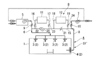
本実施形態のクリーンルーム(除染対象室)1は、図1に示すように、従来周知の空調システムAを備えている。この空調システムAは、クリーンルーム1に設けられ、HEPAフィルタ2が設置された吹出口3及び吸込口4と、吹出口3とクリーンルーム1の外側の外調機5とに繋がる給気ダクト6と、吸込口4とクリーンルーム1の外側の排気ファン7とに繋がる還気ダクト8とを備えて構成されている。また、給気ダクト6と還気ダクト8にはそれぞれ開閉弁(第1開閉弁9、第2開閉弁10)が設けられている。
A clean room (decontamination target room) 1 according to the present embodiment includes a conventionally known air conditioning system A as shown in FIG. This air conditioning system A is provided in the
そして、このクリーンルーム1の空調システムAによれば、第1開閉弁9を開いた状態で外調機5を駆動すると、外気が給気ダクト6を通じて吹出口3に送気され、HEPAフィルタ2を通過するとともに吹出口3からクリーンルーム1内に供給される。また、第2開閉弁10を開いた状態で排気ファン7を駆動すると、クリーンルーム1内の空気(還気)が還気ダクト8を通じて外部に送気され、外調機5に送られる。このとき、還気ダクト8を通じて外部に送気された空気の一部は、外部に排気される。これにより、空調システムAによる通常空調運転時には、図2に示すように、クリーンルーム1内に清浄化した空気が通常空調ラインS1で流通して循環する。
According to the air conditioning system A of the
一方、本実施形態の室内除染システムBは、除染剤に過酸化水素を使用してクリーンルームを除染するシステムであり、図1に示すように、過酸化水素発生装置11と過酸化水素分解装置12を備えて構成されている。過酸化水素発生装置11は、例えば、過酸化水素水を貯留するタンクから送水ポンプの駆動とともに過酸化水素水を吸引し、これとともに過酸化水素水を加熱面に滴下してフラッシュ蒸発させて、過酸化水素ガス(過酸化水素蒸気)を発生させるように構成されている。また、過酸化水素分解装置12は、触媒として白金触媒などを備え、過酸化水素ガスを含む空気から過酸化水素を白金触媒などで分解して除去するように構成されている。
On the other hand, the indoor decontamination system B of the present embodiment is a system for decontaminating a clean room using hydrogen peroxide as a decontamination agent. As shown in FIG. A
また、本実施形態の室内除染システムBでは、空調システムAの給気ダクト6と還気ダクト8に繋げて連絡ダクト15が架設されている。この連絡ダクト15は、一端を給気ダクト6の第1開閉弁9と吹出口3の間に、他端を還気ダクト8の第2開閉弁10と吸込口4の間にそれぞれ繋げて設けられている。すなわち、給気ダクト6の一部と還気ダクト8の一部と連絡ダクト15とで循環ダクトが構成されている。
Further, in the indoor decontamination system B of the present embodiment, a
そして、過酸化水素発生装置11は、連絡ダクト15に第1排気ダクト16と第1給気ダクト17を介して接続されている。また、過酸化水素分解装置12は、連絡ダクト15に第2排気ダクト18と第2給気ダクト19を介して接続されている。さらに、連絡ダクト15には、第1排気ダクト16と第1給気ダクト17のそれぞれの接続部の間に循環ファン20が設けられ、過酸化水素分解装置12の第2排気ダクト18と第2給気ダクト19のそれぞれの接続部の間に第3開閉弁(切替機構)21が設けられている。
The
また、過酸化水素発生装置11と連絡ダクト15を繋ぐ第1排気ダクト16と第1給気ダクト17には、第4開閉弁(切替機構)22と第5開閉弁(切替機構)23がそれぞれ設けられ、過酸化水素分解装置12と連絡ダクト15を繋ぐ第2給気ダクト19には、第6開閉弁(切替機構)24が設けられている。
In addition, a fourth open / close valve (switching mechanism) 22 and a fifth open / close valve (switching mechanism) 23 are respectively provided in the
さらに、本実施形態では、連絡ダクト15、第1給気ダクト17、第2給気ダクト19、還気ダクト8の外側にグラスウール等の断熱材が巻かれており、これらダクト15、17、19、8に断熱処理が施されている。
Further, in this embodiment, a heat insulating material such as glass wool is wound around the outside of the
そして、上記構成からなる本実施形態の室内除染システムBでクリーンルーム1の除染作業を行う際には、はじめに、注入運転を行う。通常空調運転から注入運転に切り替える際には、空調システムAの第1開閉弁9と第2開閉弁10を閉じ、第3開閉弁21、第4開閉弁22、第5開閉弁23を開くとともに循環ファン20を駆動する。これにより、図3に示すように、循環ファン20の駆動によって、過酸化水素発生装置11の第1排気ダクト16から連絡ダクト15、連絡ダクト15から給気ダクト6、給気ダクト6からクリーンルーム1、クリーンルーム1から還気ダクト8、還気ダクト8から連絡ダクト15、連絡ダクト15から過酸化水素発生装置11の第1給気ダクト17に空気が流通して循環し、通常空調運転時の通常空調ラインS1から注入運転時の放出ラインS2に切り替わる。
And when performing the decontamination operation | work of the
また、本実施形態では、通常空調ラインS1から放出ラインS2に切替えるとともに(除染前に)、断熱処理を施したダクト15、17、19、8内を加温しておく。
Moreover, in this embodiment, while switching from the normal air conditioning line S1 to the discharge line S2 (before decontamination), the inside of the
このように放出ラインS2に切替えた段階で、過酸化水素発生装置11を駆動し、この過酸化水素発生装置11で発生した過酸化水素ガスを放出ラインS2に放出する。これにより、放出ラインS2によって過酸化水素ガスを含む空気が循環し、過酸化水素ガスがクリーンルーム1に供給される。また、過酸化水素発生装置11から所定の過酸化水素投入量の過酸化水素を投入した段階で過酸化水素発生装置11の駆動を停止する。そして、本実施形態では、ダクト15、17、19、8に断熱処理が施されるとともに、これらダクト15、17、19、8内が加温されているため、放出ラインS2で過酸化水素ガスを含む空気が循環する際に、過酸化水素がダクト15、17、19、8で結露することがない。このため、従来の室内除染システムと比較し、過酸化水素投入量が少なくて済む。
At the stage of switching to the discharge line S2, the
また、このように注入運転によって所定の過酸化水素投入量の過酸化水素を投入した段階で、保持運転を行う。この保持運転では、図4に示すように、第4開閉弁22と第5開閉弁23を閉じ、連絡ダクト15と給気ダクト6とクリーンルーム1と還気ダクト8の放出ラインS2’で過酸化水素ガスを含む空気を循環させる。これにより、所定濃度の過酸化水素を含む空気が確実にクリーンルーム1に供給され、クリーンルーム1内の増殖可能な芽胞菌が殺滅されてクリーンルーム1が除染される。また、このとき、クリーンルーム1だけでなく、空調システムAの給気ダクト6、吹出口3及び吸込口4、HEPAフィルタ2、還気ダクト8に過酸化水素ガスを含む空気が流通して循環するため、連絡ダクト15、循環ファン20を含む放出ラインS2、S2’の循環系統全体がクリーンルーム1を除染すると同時に除染される。さらに、空調システムA(空調システムAの吹出口3、吸込口4等)を利用して過酸化水素ガスをクリーンルーム1に供給することで、クリーンルーム1内に均一に過酸化水素が供給される。このため、好適且つ確実にクリーンルーム1内が除染されることになる。
In addition, the holding operation is performed at the stage where a predetermined amount of hydrogen peroxide is charged by the injection operation. In this holding operation, as shown in FIG. 4, the fourth on-off
ついで、クリーンルーム1の除染が完了した段階で分解運転を行う。この分解運転(エアレーション分解)では、第3開閉弁21を閉じるとともに第6開閉弁24を開く。これにより、図5に示すように、過酸化水素分解装置12の第2排気ダクト18から連絡ダクト15、連絡ダクト15から給気ダクト6、給気ダクト6からクリーンルーム1、クリーンルーム1から還気ダクト8、還気ダクト8から連絡ダクト15、連絡ダクト15から過酸化水素分解装置12の第2給気ダクト19に過酸化水素ガスを含む空気が流通して循環し、保持運転時の放出ラインS2’から分解運転時の分解ラインS3に切り替わる。
Next, the decomposition operation is performed when the decontamination of the
このように分解ラインS3に切替えることで、順次クリーンルーム1から過酸化水素分解装置12に過酸化水素ガスを含む空気が導入され、過酸化水素分解装置12によって過酸化水素が分解・減衰される。そして、この分解運転は、循環空気中の過酸化水素が安全な濃度レベル(例えば1ppm以下)になるまで行われる。なお、本実施形態の過酸化水素分解装置12は、過酸化水素を分解するための触媒として白金触媒を使用するようにしているが、他の触媒を使用することも可能であり、他の触媒の候補としては、二酸化マンガン、ニッケル、銅などの金属や、酵素類、活性炭等がある。
By switching to the decomposition line S3 in this way, air containing hydrogen peroxide gas is sequentially introduced from the
ついで、分解運転によって空気中の過酸化水素が安全な濃度レベルまで分解された段階で外気導入運転を行う。この外気導入運転では、第6開閉弁24を閉じて循環ファン20の駆動を停止する。また、これとともに、第1開閉弁9と第2開閉弁10を開き、外調機5を駆動する。これにより、図6に示すように、通常空調ラインS1と同様の外気導入ラインS1’でクリーンルーム1内に清浄化した空気が流通し、過酸化水素濃度の減衰速度が低下する低濃度域でこの外気導入運転に切り替えることによって、クリーンルーム1内の過酸化水素濃度低下を促進する。なお、この外気導入運転時には、クリーンルーム1から還気ダクト8を通じて排出された全ての空気を外部に排気する。また、この外気導入運転は、使用者の判断で適宜選択的に行えばよい。
Next, the outside air introduction operation is performed when hydrogen peroxide in the air is decomposed to a safe concentration level by the decomposition operation. In this outside air introduction operation, the sixth on-off
そして、上記のように通常空調運転から、注入運転、保持運転、分解運転、外気導入運転を行うことで、クリーンルーム1の除染作業が完了する。また、このとき、空調システムAと室内除染システムBを統合制御し、注入運転、保持運転、分解運転の除染の一連動作を自動化するようにしてもよい。また、この場合には、除染全自動運転への切替を空調制御盤タッチパネルで操作するようにしてもよい。なお、このように除染の一連動作を自動化する場合において、外気導入運転は手動で行えるようにしてもよい。
Then, the decontamination work of the
ここで、本実施形態に係る室内除染システムBによってクリーンルーム1の除染を行った実証実験について説明する。
Here, a demonstration experiment in which the
本実証実験のクリーンルーム1は、バイオロジカルクリーンルームであり、室容積が約51m3(2.7m×7.0m×2.7m(W×D×H))、ダクト等の設備を含めた除染時循環系の系内容積が約53m3である。
The
また、過酸化水素発生装置11は、澁谷工業株式会社製のHYDEC2100を使用し、過酸化水素分解装置12には白金触媒で過酸化水素を分解する装置を使用している。
Moreover, the
また、過酸化水素(H2O2)は35%重量濃度で安定剤の少ない電子用を使用し、過酸化水素発生装置11の注入速度を20g/min、送風量を40m3/hに設定した。そして、実験パラメータは、注入量(過酸化水素投入量)、保持時間、循環風量、初期相対湿度の4項目で検討を行っている。
Also, hydrogen peroxide (H 2 O 2 ) is used for 35% weight concentration and less electronic stabilizer, the
ここで、BI(バイオロジカル・インジケーター)の定義では、対象とする滅菌法に対して最抵抗性菌(最も生存しやすい強い菌)を用いることになっており、VPHP(過酸化水素蒸気)の場合には、Geobacillus stearothermophilusの芽胞でステンレス担体のものがBIとして使用される。このため、本実証実験において、BIには、Apex Laboratories社製のGeobacillus stearothermophilus ATCC12980 芽胞をステンレス製ディスク担体に接種したものを使用している。また、このBIは、高密度ポリエチレン製のタイベックで作られた小さな袋(28mm×64mm)内に収められている。そして、BIは、図1及び図7に示すように、除染が容易と予想されるテーブル25の上(BI−1)と、除染しにくいと予想されるテーブル25の下の床上(BI−2)と、吹出口3の直下でない床上(4つの吹出口3から等距離の床面上)(BI−3)と、隅角部の床上(BI−4)とに設置した。 Here, in the definition of BI (biological indicator), the most resistant bacterium (the strongest bacterium that is most likely to survive) is used for the target sterilization method, and VPHP (hydrogen peroxide vapor) is used. In some cases, Geobacillus stearothermophilus spores with stainless steel support are used as BI. For this reason, in this demonstration experiment, what used inoculated Geobacillus stearothermophilus ATCC12980 spore made from Apex Laboratories on the stainless steel disc support | carrier was used for BI. The BI is contained in a small bag (28 mm × 64 mm) made of high-density polyethylene tyvek. As shown in FIG. 1 and FIG. 7, the BI is on the table 25 (BI-1) where decontamination is expected to be easy and on the floor (BI-1) below the table 25 where decontamination is expected to be difficult. -2), on the floor that is not directly under the outlet 3 (on the floor surface equidistant from the four outlets 3) (BI-3), and on the corner floor (BI-4).
ここで、過酸化水素濃度の測定は、除染循環系各部での濃度の同時多点計測によって行っており、純水インピンジャーに捕集した過酸化水素を、過マンガン酸カリウムを用いて酸化滴定することによって濃度を求めた。また、このインピンジャーへの捕集時間は、昇温・注入・保持の時間帯(約1時間)で、吸引流量を1L/minとした。さらに、濃度の経時変化測定は、過酸化水素濃度センサー(ポリトロン7000、ドレーゲル社製、13×13×16cm)で測定した。 Here, the hydrogen peroxide concentration is measured by simultaneous multipoint measurement of the concentration in each part of the decontamination circulation system. The hydrogen peroxide collected in the pure water impinger is oxidized using potassium permanganate. The concentration was determined by titration. Moreover, the collection time to this impinger was the time of temperature increase, injection, and holding (about 1 hour), and the suction flow rate was 1 L / min. Further, the concentration change with time was measured with a hydrogen peroxide concentration sensor (Polytron 7000, manufactured by Dräger, 13 × 13 × 16 cm).
本実施例のBI試験結果を表1に示す。実験No.1〜3では、投入量を400gで一定とし、初期相対湿度を変化させている。そして、この結果、初期相対湿度が高いほど到達濃度(室内における最高濃度)が低くなることが確認された。この要因として、ダクト内表面などでの過酸化水素の結露に伴う濃度低下、さらに水蒸気結露に伴う濃度低下が起こりやすくなるなどが考えられる。なお、過酸化水素の露点温度は水蒸気の露点温度より高いため、過酸化水素の結露は水蒸気の結露より先に起こると考えられる。また、実験No.1〜3の全てのケースでテーブル下床(BI−2)のBIが陽性を示した。これは、気流が到達しにくいためと考えられる。
The BI test results of this example are shown in Table 1. Experiment No. 1 to 3, the input amount is constant at 400 g, and the initial relative humidity is changed. As a result, it was confirmed that the reached concentration (the highest concentration in the room) decreases as the initial relative humidity increases. As this factor , it is conceivable that a decrease in the concentration due to the dew condensation of hydrogen peroxide on the inner surface of the duct and the like, and a decrease in the concentration due to the dew condensation of water vapor easily occur. Since the dew point temperature of hydrogen peroxide is higher than the dew point temperature of water vapor, it is considered that the dew point of hydrogen peroxide occurs before the dew point of water vapor. In addition, Experiment No. In all
ついで、実験No.4〜7では、投入量と保持時間の効果を検討した。この結果、500g投入すれば、保持時間が20分でも(実験No.1〜3の30分より短くても)、BIは全て陰性となった。また、実験No.6で400g投入し保持時間を40分とした場合でもBIは全て陰性となった。 Next, Experiment No. In 4-7, the effect of the input amount and the holding time was examined. As a result, when 500 g was added, even if the holding time was 20 minutes (even if it was shorter than 30 minutes in Experiments Nos. 1 to 3), BI was all negative. In addition, Experiment No. Even when 400 g was added at 6 and the holding time was 40 minutes, all BIs were negative.
一方、実験No.7で300g投入し保持時間を60分とした場合、BIは2箇所で陽性となった。このことから、投入量の方が保持時間よりも除染効果に対して大きく影響することが確認された。 On the other hand, Experiment No. When 300 g was added in 7 and the holding time was 60 minutes, BI was positive in two places. From this, it was confirmed that the input amount has a greater influence on the decontamination effect than the retention time.
ついで、実験No.8〜12では、投入量を500g、保持時間を20分とした条件で、循環風量を変化させた。この結果、循環風量の大小に関係なくBIは全て陰性になることが確認された。 Next, Experiment No. In Nos. 8 to 12, the circulating air flow was changed under the conditions where the input amount was 500 g and the holding time was 20 minutes. As a result, it was confirmed that BI was all negative regardless of the amount of circulating air.

そして、図8は、好成績をあげた実験No.4と実験No.5におけるエアレーション(分解運転)を含めた全時間帯について、過酸化水素濃度センサーで測定した過酸化水素濃度の経時変化を示している。なお、この過酸化水素濃度の経時変化は、吹出口3と吸込口4の2箇所で計測している。
FIG. 8 shows the experiment No. 1 with good results. 4 and Experiment No. 5 shows the change over time in the hydrogen peroxide concentration measured by the hydrogen peroxide concentration sensor for the entire time zone including the aeration (decomposition operation) in FIG. The change with time in the hydrogen peroxide concentration is measured at two locations, the
この結果から、注入・保持時では、吹出口3と吸込口4の濃度はほぼ等しく、システムBが順調に稼動しており、室内での過酸化水素の分解は殆んどないことが確認できる。また、エアレーション分解時では、白金触媒フィルタで分解された循環空気(還気)が出る吹出口3の濃度は急激に低下しているが、吸込口4の濃度は徐々に低下していた。これは、吸込口4に入る空気には、室内空気に蓄積された過酸化水素に加えて、室内表面から再放出した過酸化水素残留分(結露分、吸着分)が含まれているためであると考えられる。
From this result, at the time of injection / holding, it can be confirmed that the concentration of the
以上の結果から、過酸化水素の除染と分解が円滑に稼動し、現状でもシステムとして十分に施設へ展開できることが実証された。また、検討した4項目のパラメータのうち、過酸化水素溶液(35%)投入量が最も除染に影響があることが実証された。さらに、室内相対湿度が高いと室内の過酸化水素濃度が低下する傾向が見られ、ダクト内表面などでの水蒸気結露や、室内表面での過酸化水素結露が影響することが確認された。 From the above results, it was proved that the decontamination and decomposition of hydrogen peroxide worked smoothly, and that the system can be fully deployed to the facility even in the present situation. In addition, among the four parameters studied, it was proved that the input amount of hydrogen peroxide solution (35%) had the most influence on decontamination. Furthermore, when the indoor relative humidity was high, the hydrogen peroxide concentration in the room tended to decrease, and it was confirmed that water vapor condensation on the inner surface of the duct and the hydrogen peroxide condensation on the indoor surface had an effect.
したがって、本実施形態の室内除染システムBにおいては、過酸化水素発生装置11と過酸化水素分解装置12を、循環ダクト(連絡ダクト15)に沿って切替機構22、23、24を介して直列に配置し、放出ラインS2(S2’)と分解ラインS3が同一の循環ダクト(連絡ダクト15、空調システムAの給気ダクト6及び還気ダクト8)を利用して構成されているため、放出ラインS2と分解ラインS3にそれぞれ個別のダクトを設けるようにした従来の室内除染システムと比較して、ダクトの量を少なくすることができる。これにより、ダクトの量を必要最小限にして省スペース化及び低コスト化を図り、効率的且つ確実に除染を行うことが可能になる。
Therefore, in the indoor decontamination system B of the present embodiment, the
また、建築空調システムAのダクト(給気ダクト6、還気ダクト8)を循環ダクトに利用することで、この空調システムAのクリーンルーム(除染対象室)1に設けられた吹出口3と吸込口4を活かして、過酸化水素を均一にクリーンルーム1に供給することが可能になる。さらに、このように空調システムAのダクト6、8を循環ダクトに利用することで、クリーンルーム1だけでなく、空調システムAのダクト6、8、循環ファン20、吹出口3及び吸込口4に設けたHEPAフィルタ2など、循環系統全体を除染することが可能になる。これにより、効率的且つ確実に除染を行うことが可能になる。
Further, by using the ducts of the building air conditioning system A (the
さらに、除染前に、すなわち過酸化水素を供給する前に、クリーンルーム1から過酸化水素発生装置11及び/又は過酸化水素分解装置12に空気を戻すダクト15、17、19、8内を加温しておくことで、この断熱処理したダクト15、17、19、8内の温度を高めて保持することができる。これにより、放出ラインS2や分解ラインS3で過酸化水素を含む空気が循環した場合であっても、ダクト15、17、19、8内に結露が発生することを防止できる。よって、従来の室内除染システムと比較し、所要の室内過酸化水素濃度を達成するための過酸化水素投入量が少なくて済み、除染性能を向上させることが可能になる。
Further, before decontamination, that is, before supplying hydrogen peroxide, the inside of the
以上、本発明に係る建物の室内除染システムの一実施形態について説明したが、本発明は上記の一実施形態に限定されるものではなく、その趣旨を逸脱しない範囲で適宜変更可能である。例えば、本実施形態では、除染対象室を無菌製剤クリーンルームであるものとして説明を行ったが、本発明の室内除染システムは、他のクリーンルームに適用してもよい。 As mentioned above, although one Embodiment of the indoor decontamination system of the building which concerns on this invention was described, this invention is not limited to said one Embodiment, In the range which does not deviate from the meaning, it can change suitably. For example, in the present embodiment, the decontamination target room has been described as being an aseptic preparation clean room, but the indoor decontamination system of the present invention may be applied to other clean rooms.
また、本発明に係る建物の室内除染システムは、過酸化水素発生装置11と過酸化水素分解装置12を各種センサーと連動させて制御することも可能である。このため、各種センサーによってセンシングした種々の物理量の値を反映させて、室内除染システムを最適運転させるようにしてもよい。そして、この場合、センサーとしては、結露センサー、温湿度センサー、過酸化水素センサー、差圧センサーなどを適用でき、特に結露センサーを用いると有効である。
The building indoor decontamination system according to the present invention can also control the
具体的に、過酸化水素のある程度の結露は、除染に有効であり、一般に、これを「マイクロコンデンセーション理論」と呼んでいる。そして、過酸化水素の蒸気圧は水の蒸気圧より低いため、すなわち、過酸化水素の露点温度は水蒸気の露点温度よりも高いため、過酸化水素の結露は水蒸気の結露より先に起こると考えられる。例えば、35wt%(30℃)の過酸化水素水の飽和蒸気圧は23mmHgであり、そのときの過酸化水素分圧は0.36mmHg、水分圧は22.64mmHgである。なお、水のみ(30℃)の飽和蒸気圧は32mmHgである。このため、水が結露する温湿度条件では過酸化水素も当然結露することになる。一方、過酸化水素の過剰な結露は、薬液(過酸化水素水溶液)の無駄であり、また、除染系内(室内の内装材、機器類、循環ダクト等)への腐食負荷が大きくなる。以上のことを勘案すると、除染時循環系内では、過酸化水素を過剰にならないように結露させ、水を結露させないようにすることで、過酸化水素の結露を除染に有効に活用することが可能になる。 Specifically, a certain degree of condensation of hydrogen peroxide is effective for decontamination, and this is generally called “microcondensation theory”. And since the vapor pressure of hydrogen peroxide is lower than the vapor pressure of water, that is, the dew point temperature of hydrogen peroxide is higher than the dew point temperature of water vapor, the dew point of hydrogen peroxide is considered to occur before the dew point of water vapor. It is done. For example, the saturated vapor pressure of 35 wt% (30 ° C.) hydrogen peroxide water is 23 mmHg, the hydrogen peroxide partial pressure at that time is 0.36 mmHg, and the water pressure is 22.64 mmHg. The saturated vapor pressure of only water (30 ° C.) is 32 mmHg. For this reason, hydrogen peroxide also naturally condenses under temperature and humidity conditions where water condenses. On the other hand, excessive dew condensation of hydrogen peroxide is a waste of chemical solution (hydrogen peroxide aqueous solution), and the corrosion load on the decontamination system (indoor interior materials, equipment, circulation ducts, etc.) becomes large. Considering the above, in the circulation system at the time of decontamination, hydrogen peroxide is condensed so that it does not become excessive, and water is not condensed, so that the condensation of hydrogen peroxide is effectively used for decontamination. It becomes possible.
そして、本発明に係る建物の室内除染システムにおいては、結露センサー、温湿度センサー、過酸化水素センサー、差圧センサーなどによって循環空気の温湿度と室内内表面・循環ダクトの内表面をセンシングし、その結果を空調制御にフィードバックし、過酸化水素を過剰にならないように結露させ、水を結露させないように循環空気の温湿度コントロールと循環ダクト内の加熱を適宜行うようにすることで、過酸化水素の結露を除染に有効に活用することが可能になる。 In the indoor decontamination system for buildings according to the present invention, the temperature / humidity of the circulating air and the indoor surface / inner surface of the circulation duct are sensed by a dew condensation sensor, a temperature / humidity sensor, a hydrogen peroxide sensor, a differential pressure sensor, etc. The result is fed back to the air-conditioning control, condensation is performed so that hydrogen peroxide does not become excessive, and temperature and humidity control of the circulating air and heating in the circulation duct are appropriately performed so as not to condense water. It becomes possible to effectively utilize the condensation of hydrogen oxide for decontamination.
1 クリーンルーム(除染対象室)
2 HEPAフィルタ
3 吹出口
4 吸込口
5 外調機
6 給気ダクト
7 排気ファン
8 還気ダクト
9 第1開閉弁
10 第2開閉弁
11 過酸化水素発生装置
12 過酸化水素分解装置
15 連絡ダクト
16 第1排気ダクト
17 第1給気ダクト
18 第2排気ダクト
19 第2給気ダクト
20 循環ファン
21 第3開閉弁(切替機構)
22 第4開閉弁(切替機構)
23 第5開閉弁(切替機構)
24 第6開閉弁(切替機構)
25 テーブル
A 空調システム
B 室内除染システム
S1 通常空調ライン
S2 放出ライン
S2’放出ライン
S3 分解ライン
S1’外気導入ライン
1 Clean room (Decontamination target room)
2
22 4th on-off valve (switching mechanism)
23 Fifth open / close valve (switching mechanism)
24 6th on-off valve (switching mechanism)
25 Table A Air conditioning system B Indoor decontamination system S1 Normal air conditioning line S2 Release line S2 'Release line S3 Disassembly line
S1 ' outside air introduction line
Claims (2)
前記除染対象室に設けられた吹出口と前記除染対象室の外側に配置された外調機とを連結する給気ダクトと、
前記給気ダクトに設けられ、該給気ダクトを開閉する第1開閉弁と、
前記除染対象室に設けられた吸込口と前記除染対象室の外側に配置された排気ファンとを連結する還気ダクトと、
前記還気ダクトに設けられ、該還気ダクトを開閉する第2開閉弁と、
一端を前記給気ダクトの第1開閉弁と前記吹出口との間に、他端を前記還気ダクトの第2開閉弁と前記吸込口との間に連結された連絡ダクトと、
前記連絡ダクトに接続された第1給気ダクトと第1排気ダクトとの間に配置されるとともに、過酸化水素水を気化させて過酸化水素ガスを発生させる過酸化水素発生装置と、
前記連絡ダクトに接続された第2給気ダクトと第2排気ダクトとの間に配置されるとともに、空気中に含まれる過酸化水素を分解する過酸化水素分解装置と、
前記連絡ダクトの前記第2給気ダクトと前記第2排気ダクトのそれぞれの接続部の間に設けられた第3開閉弁と、
前記第1排気ダクトに設けられ、該第1排気ダクトを開閉する第4開閉弁と、
前記第1給気ダクトに設けられ、該第1給気ダクトを開閉する第5開閉弁と、
前記第2給気ダクトに設けられ、該第2給気ダクトを開閉する第6開閉弁とを備え、
前記過酸化水素発生装置と前記過酸化水素分解装置とが前記連絡ダクトに沿って直列に配置されており、
前記過酸化水素ガスを前記除染対象室に注入する注入運転時には、前記第1開閉弁と前記第2開閉弁と前記第6開閉弁を閉じるとともに、前記第3開閉弁と前記4開閉弁と前記第5開閉弁を開き、
前記過酸化水素発生装置で発生させた過酸化水素ガスを含む空気を、前記過酸化水素発生装置から前記第1排気ダクト、前記第1排気ダクトから前記連絡ダクト、前記連絡ダクトから前記給気ダクト、前記給気ダクトから前記除染対象室、前記除染対象室から前記還気ダクト、前記還気ダクトから前記連絡ダクト、前記連絡ダクトから前記第1給気ダクト、前記第1給気ダクトから前記過酸化水素発生装置に流通して循環させ、
前記過酸化水素ガスを分解する分解運転時には、前記第1開閉弁と前記第2開閉弁と前記第3開閉弁と前記第4開閉弁と前記第5開閉弁を閉じるとともに、前記第6開閉弁を開き、
前記過酸化水素ガスを含む空気を、前記過酸化水素分解装置から前記第2排気ダクト、前記第2排気ダクトから前記連絡ダクト、前記連絡ダクトから前記給気ダクト、前記給気ダクトから前記除染対象室、前記除染対象室から前記還気ダクト、前記還気ダクトから前記連絡ダクト、前記連絡ダクトから前記第2給気ダクト、前記第2給気ダクトから前記過酸化水素分解装置に流通して循環させるように構成されていることを特徴とする室内除染システム。 An indoor decontamination system for decontaminating a decontamination target room using hydrogen peroxide,
An air supply duct that connects an outlet provided in the decontamination target chamber and an external air conditioner disposed outside the decontamination target chamber;
A first on-off valve provided in the air supply duct for opening and closing the air supply duct;
A return air duct that connects a suction port provided in the decontamination target chamber and an exhaust fan disposed outside the decontamination target chamber;
A second on-off valve provided in the return air duct for opening and closing the return air duct;
A communication duct having one end connected between the first on-off valve of the air supply duct and the outlet and the other end connected between the second on-off valve of the return air duct and the suction port;
A hydrogen peroxide generator disposed between the first air supply duct and the first exhaust duct connected to the communication duct and generating hydrogen peroxide gas by vaporizing hydrogen peroxide water;
A hydrogen peroxide decomposition apparatus that is disposed between the second air supply duct and the second exhaust duct connected to the communication duct and decomposes hydrogen peroxide contained in the air;
A third on-off valve provided between each connection portion of the second air supply duct and the second exhaust duct of the communication duct;
A fourth on-off valve provided in the first exhaust duct for opening and closing the first exhaust duct;
A fifth on-off valve provided in the first air supply duct for opening and closing the first air supply duct;
A sixth on-off valve provided in the second air supply duct for opening and closing the second air supply duct ;
The hydrogen peroxide generating device and the hydrogen peroxide decomposing device are arranged in series along the communication duct,
During the injection operation of injecting the hydrogen peroxide gas into the decontamination target chamber, the first on-off valve, the second on-off valve, and the sixth on-off valve are closed, and the third on-off valve, the fourth on-off valve, Open the fifth on-off valve;
Air containing hydrogen peroxide gas generated by the hydrogen peroxide generator is supplied from the hydrogen peroxide generator to the first exhaust duct, from the first exhaust duct to the communication duct, and from the communication duct to the air supply duct. From the air supply duct to the decontamination target chamber, from the decontamination target chamber to the return air duct, from the return air duct to the communication duct, from the communication duct to the first air supply duct, from the first air supply duct Circulate and circulate through the hydrogen peroxide generator,
During the decomposition operation for decomposing the hydrogen peroxide gas, the first on-off valve, the second on-off valve, the third on-off valve, the fourth on-off valve, and the fifth on-off valve are closed, and the sixth on-off valve Open
The air containing the hydrogen peroxide gas, the from the hydrogen peroxide decomposition device a second exhaust duct, the contact duct from said second exhaust duct, the air supply duct from the communication duct, the decontamination from the air supply duct The target chamber, the return air duct from the decontamination target chamber, the communication duct from the return air duct, the second air supply duct from the communication duct, and the hydrogen supply decomposition device from the second air supply duct. An indoor decontamination system characterized by being configured to circulate.
前記連絡ダクトと前記第1給気ダクトと前記第2給気ダクトと前記還気ダクトに、外側に断熱材を巻き付けて断熱処理が施されており、
除染前に、前記断熱材を巻き付けた前記連絡ダクトと前記第1給気ダクトと前記第2給気ダクトと前記還気ダクトを加温しておくように構成されていることを特徴とする室内除染システム。 The indoor decontamination system according to claim 1,
A heat insulating material is wound around the outside of the connecting duct, the first air supply duct, the second air supply duct, and the return air duct, and heat treatment is performed.
Before the decontamination, the connecting duct, the first air supply duct, the second air supply duct, and the return air duct around which the heat insulating material is wound are configured to be heated. Indoor decontamination system.
Priority Applications (1)
| Application Number | Priority Date | Filing Date | Title |
|---|---|---|---|
| JP2009158015A JP5452997B2 (en) | 2009-07-02 | 2009-07-02 | Indoor decontamination system |
Applications Claiming Priority (1)
| Application Number | Priority Date | Filing Date | Title |
|---|---|---|---|
| JP2009158015A JP5452997B2 (en) | 2009-07-02 | 2009-07-02 | Indoor decontamination system |
Publications (2)
| Publication Number | Publication Date |
|---|---|
| JP2011010892A JP2011010892A (en) | 2011-01-20 |
| JP5452997B2 true JP5452997B2 (en) | 2014-03-26 |
Family
ID=43590321
Family Applications (1)
| Application Number | Title | Priority Date | Filing Date |
|---|---|---|---|
| JP2009158015A Active JP5452997B2 (en) | 2009-07-02 | 2009-07-02 | Indoor decontamination system |
Country Status (1)
| Country | Link |
|---|---|
| JP (1) | JP5452997B2 (en) |
Families Citing this family (8)
| Publication number | Priority date | Publication date | Assignee | Title |
|---|---|---|---|---|
| JP5769462B2 (en) * | 2011-03-24 | 2015-08-26 | 株式会社エアレックス | Decontamination condition determination method |
| JP6132189B2 (en) * | 2013-03-07 | 2017-05-24 | 武田薬品工業株式会社 | Decontamination method for biohazard facilities |
| CN103263681B (en) * | 2013-05-27 | 2015-04-08 | 上海东富龙爱瑞思科技有限公司 | Integrated room vaporization hydrogen peroxide sterilization system |
| CN103363636B (en) * | 2013-07-29 | 2016-04-13 | 浙江新澳纺织股份有限公司 | A kind of spinning workshop humiture automatic cycle regulating system |
| WO2016172223A1 (en) * | 2015-04-20 | 2016-10-27 | Synexis Llc | Clean rooms having dilute hydrogen peroxide (dhp) gas and methods of use thereof |
| JP7027239B2 (en) * | 2018-04-24 | 2022-03-01 | 株式会社日立産機システム | Sterilization gas purification closed system equipment |
| JP6889809B2 (en) * | 2018-06-20 | 2021-06-18 | 日揮株式会社 | Bacterial treatment mechanism and bacterial treatment method |
| CN112339973B (en) * | 2020-11-06 | 2022-06-10 | 军事科学院系统工程研究院卫勤保障技术研究所 | Positive and negative pressure fast switching control system and method for ship cabin |
Family Cites Families (7)
| Publication number | Priority date | Publication date | Assignee | Title |
|---|---|---|---|---|
| DE2740738A1 (en) * | 1977-09-09 | 1979-03-22 | Stierlen Maquet Ag | PROCEDURE AND EQUIPMENT FOR DISINFECTING THE OPERATING ROOM OF A HOSPITAL |
| US4863688A (en) * | 1986-12-31 | 1989-09-05 | American Sterilizer Company | Method of decontaminating surfaces on or near living cells with vapor hydrogen peroxide |
| JP2760909B2 (en) * | 1991-04-30 | 1998-06-04 | 大成建設株式会社 | Fumigation equipment |
| JP4490538B2 (en) * | 2000-02-03 | 2010-06-30 | 株式会社テクノ菱和 | Formaldehyde decomposition apparatus, air conditioner with a catalyst for formaldehyde decomposition, fumigation system with formaldehyde generation apparatus and decomposition apparatus, and formaldehyde generation / decomposition apparatus |
| JP4529593B2 (en) * | 2004-08-31 | 2010-08-25 | 澁谷工業株式会社 | Isolator system |
| JP4508094B2 (en) * | 2005-10-13 | 2010-07-21 | ダイキン工業株式会社 | Sterilization system |
| JP2007105230A (en) * | 2005-10-13 | 2007-04-26 | Daikin Ind Ltd | Sterilizing apparatus |
-
2009
- 2009-07-02 JP JP2009158015A patent/JP5452997B2/en active Active
Also Published As
| Publication number | Publication date |
|---|---|
| JP2011010892A (en) | 2011-01-20 |
Similar Documents
| Publication | Publication Date | Title |
|---|---|---|
| JP5452997B2 (en) | Indoor decontamination system | |
| EP1933886B1 (en) | Method for refreshing a hotel room with hydrogen peroxide vapor | |
| JP4377910B2 (en) | Building decontamination using steam hydrogen peroxide | |
| JP5590797B2 (en) | Disinfection of space | |
| US20060008379A1 (en) | Room decontamination with hydrogen peroxide vapor | |
| Krause et al. | Biodecontamination of animal rooms and heat-sensitive equipment with vaporized hydrogen peroxide | |
| JP5823957B2 (en) | Decontamination of enclosed spaces using gaseous chlorine dioxide | |
| JP5462025B2 (en) | Isolator, automatic cell culture device, and isolator sterilization method | |
| JP6336112B2 (en) | A greatly enhanced decontamination method with hydrogen peroxide vaporized at low concentrations | |
| MX2007014983A (en) | An integrated decontamination/aeration system for vehicles. | |
| EP2968632B1 (en) | Process for focused gas phase application of biocide | |
| KR101116042B1 (en) | The ultrasonic humidifier type h2o2 sterilising apparatus for the medical instrument | |
| Krishnan et al. | Evaluation of a dry fogging system for laboratory decontamination | |
| JP2011244844A (en) | Indoor decontamination method and indoor decontamination system | |
| US20030143108A1 (en) | Apparatus and a method for decontamination | |
| JPH1176384A (en) | Ozone sterilization system for room | |
| JPH11319046A (en) | Method for sterilization, apparatus for sterilization and sterility test apparatus | |
| JP2013213657A (en) | Air conditioner | |
| JPH06169976A (en) | Disinfection apparatus and disinfection storing housing | |
| JP6628898B2 (en) | Decontamination method using chlorine dioxide gas | |
| JP2002130994A (en) | Air conditioner and its control method | |
| JP2013213656A (en) | Air conditioner |
Legal Events
| Date | Code | Title | Description |
|---|---|---|---|
| A621 | Written request for application examination |
Free format text: JAPANESE INTERMEDIATE CODE: A621 Effective date: 20120411 |
|
| A977 | Report on retrieval |
Free format text: JAPANESE INTERMEDIATE CODE: A971007 Effective date: 20121121 |
|
| A131 | Notification of reasons for refusal |
Free format text: JAPANESE INTERMEDIATE CODE: A131 Effective date: 20121127 |
|
| A521 | Written amendment |
Free format text: JAPANESE INTERMEDIATE CODE: A523 Effective date: 20130128 |
|
| A131 | Notification of reasons for refusal |
Free format text: JAPANESE INTERMEDIATE CODE: A131 Effective date: 20130319 |
|
| A521 | Written amendment |
Free format text: JAPANESE INTERMEDIATE CODE: A523 Effective date: 20130520 |
|
| TRDD | Decision of grant or rejection written | ||
| A01 | Written decision to grant a patent or to grant a registration (utility model) |
Free format text: JAPANESE INTERMEDIATE CODE: A01 Effective date: 20131217 |
|
| A61 | First payment of annual fees (during grant procedure) |
Free format text: JAPANESE INTERMEDIATE CODE: A61 Effective date: 20140106 |
|
| R150 | Certificate of patent or registration of utility model |
Ref document number: 5452997 Country of ref document: JP Free format text: JAPANESE INTERMEDIATE CODE: R150 Free format text: JAPANESE INTERMEDIATE CODE: R150 |
|
| R250 | Receipt of annual fees |
Free format text: JAPANESE INTERMEDIATE CODE: R250 |
|
| R250 | Receipt of annual fees |
Free format text: JAPANESE INTERMEDIATE CODE: R250 |
|
| R250 | Receipt of annual fees |
Free format text: JAPANESE INTERMEDIATE CODE: R250 |
|
| R250 | Receipt of annual fees |
Free format text: JAPANESE INTERMEDIATE CODE: R250 |
|
| S111 | Request for change of ownership or part of ownership |
Free format text: JAPANESE INTERMEDIATE CODE: R313117 |
|
| R350 | Written notification of registration of transfer |
Free format text: JAPANESE INTERMEDIATE CODE: R350 |