JP5451373B2 - Tool holder - Google Patents
Tool holder Download PDFInfo
- Publication number
- JP5451373B2 JP5451373B2 JP2009298334A JP2009298334A JP5451373B2 JP 5451373 B2 JP5451373 B2 JP 5451373B2 JP 2009298334 A JP2009298334 A JP 2009298334A JP 2009298334 A JP2009298334 A JP 2009298334A JP 5451373 B2 JP5451373 B2 JP 5451373B2
- Authority
- JP
- Japan
- Prior art keywords
- tool holder
- tool
- vibration
- damping material
- vibration damping
- Prior art date
- Legal status (The legal status is an assumption and is not a legal conclusion. Google has not performed a legal analysis and makes no representation as to the accuracy of the status listed.)
- Active
Links
- 238000013016 damping Methods 0.000 claims description 62
- 239000000463 material Substances 0.000 claims description 62
- 230000003014 reinforcing effect Effects 0.000 claims description 47
- 238000003754 machining Methods 0.000 claims description 11
- 230000002093 peripheral effect Effects 0.000 claims description 11
- 235000013372 meat Nutrition 0.000 claims description 9
- 239000008187 granular material Substances 0.000 claims description 7
- 230000001629 suppression Effects 0.000 claims description 5
- 230000002787 reinforcement Effects 0.000 description 7
- 229910000831 Steel Inorganic materials 0.000 description 5
- 238000006243 chemical reaction Methods 0.000 description 5
- 239000010959 steel Substances 0.000 description 5
- 230000002238 attenuated effect Effects 0.000 description 4
- 238000005553 drilling Methods 0.000 description 4
- 230000000694 effects Effects 0.000 description 4
- HMUNWXXNJPVALC-UHFFFAOYSA-N 1-[4-[2-(2,3-dihydro-1H-inden-2-ylamino)pyrimidin-5-yl]piperazin-1-yl]-2-(2,4,6,7-tetrahydrotriazolo[4,5-c]pyridin-5-yl)ethanone Chemical compound C1C(CC2=CC=CC=C12)NC1=NC=C(C=N1)N1CCN(CC1)C(CN1CC2=C(CC1)NN=N2)=O HMUNWXXNJPVALC-UHFFFAOYSA-N 0.000 description 3
- LDXJRKWFNNFDSA-UHFFFAOYSA-N 2-(2,4,6,7-tetrahydrotriazolo[4,5-c]pyridin-5-yl)-1-[4-[2-[[3-(trifluoromethoxy)phenyl]methylamino]pyrimidin-5-yl]piperazin-1-yl]ethanone Chemical compound C1CN(CC2=NNN=C21)CC(=O)N3CCN(CC3)C4=CN=C(N=C4)NCC5=CC(=CC=C5)OC(F)(F)F LDXJRKWFNNFDSA-UHFFFAOYSA-N 0.000 description 2
- 230000004308 accommodation Effects 0.000 description 2
- 239000000853 adhesive Substances 0.000 description 2
- 238000005259 measurement Methods 0.000 description 2
- 238000000034 method Methods 0.000 description 2
- 238000012545 processing Methods 0.000 description 2
- 229910001369 Brass Inorganic materials 0.000 description 1
- 230000001070 adhesive effect Effects 0.000 description 1
- 239000010951 brass Substances 0.000 description 1
- 239000002173 cutting fluid Substances 0.000 description 1
- 238000003780 insertion Methods 0.000 description 1
- 230000037431 insertion Effects 0.000 description 1
- 239000002184 metal Substances 0.000 description 1
- 239000010445 mica Substances 0.000 description 1
- 229910052618 mica group Inorganic materials 0.000 description 1
- 238000011160 research Methods 0.000 description 1
- 239000011347 resin Substances 0.000 description 1
- 229920005989 resin Polymers 0.000 description 1
- 239000004576 sand Substances 0.000 description 1
- 239000003566 sealing material Substances 0.000 description 1
- 230000003746 surface roughness Effects 0.000 description 1
Images


Classifications
-
- B—PERFORMING OPERATIONS; TRANSPORTING
- B23—MACHINE TOOLS; METAL-WORKING NOT OTHERWISE PROVIDED FOR
- B23Q—DETAILS, COMPONENTS, OR ACCESSORIES FOR MACHINE TOOLS, e.g. ARRANGEMENTS FOR COPYING OR CONTROLLING; MACHINE TOOLS IN GENERAL CHARACTERISED BY THE CONSTRUCTION OF PARTICULAR DETAILS OR COMPONENTS; COMBINATIONS OR ASSOCIATIONS OF METAL-WORKING MACHINES, NOT DIRECTED TO A PARTICULAR RESULT
- B23Q3/00—Devices holding, supporting, or positioning work or tools, of a kind normally removable from the machine
- B23Q3/12—Devices holding, supporting, or positioning work or tools, of a kind normally removable from the machine for securing to a spindle in general
-
- B—PERFORMING OPERATIONS; TRANSPORTING
- B23—MACHINE TOOLS; METAL-WORKING NOT OTHERWISE PROVIDED FOR
- B23C—MILLING
- B23C5/00—Milling-cutters
- B23C5/003—Milling-cutters with vibration suppressing means
-
- B—PERFORMING OPERATIONS; TRANSPORTING
- B23—MACHINE TOOLS; METAL-WORKING NOT OTHERWISE PROVIDED FOR
- B23Q—DETAILS, COMPONENTS, OR ACCESSORIES FOR MACHINE TOOLS, e.g. ARRANGEMENTS FOR COPYING OR CONTROLLING; MACHINE TOOLS IN GENERAL CHARACTERISED BY THE CONSTRUCTION OF PARTICULAR DETAILS OR COMPONENTS; COMBINATIONS OR ASSOCIATIONS OF METAL-WORKING MACHINES, NOT DIRECTED TO A PARTICULAR RESULT
- B23Q11/00—Accessories fitted to machine tools for keeping tools or parts of the machine in good working condition or for cooling work; Safety devices specially combined with or arranged in, or specially adapted for use in connection with, machine tools
- B23Q11/0032—Arrangements for preventing or isolating vibrations in parts of the machine
-
- B—PERFORMING OPERATIONS; TRANSPORTING
- B23—MACHINE TOOLS; METAL-WORKING NOT OTHERWISE PROVIDED FOR
- B23B—TURNING; BORING
- B23B2250/00—Compensating adverse effects during turning, boring or drilling
- B23B2250/16—Damping of vibrations
-
- B—PERFORMING OPERATIONS; TRANSPORTING
- B23—MACHINE TOOLS; METAL-WORKING NOT OTHERWISE PROVIDED FOR
- B23C—MILLING
- B23C2250/00—Compensating adverse effects during milling
- B23C2250/16—Damping vibrations
-
- Y—GENERAL TAGGING OF NEW TECHNOLOGICAL DEVELOPMENTS; GENERAL TAGGING OF CROSS-SECTIONAL TECHNOLOGIES SPANNING OVER SEVERAL SECTIONS OF THE IPC; TECHNICAL SUBJECTS COVERED BY FORMER USPC CROSS-REFERENCE ART COLLECTIONS [XRACs] AND DIGESTS
- Y10—TECHNICAL SUBJECTS COVERED BY FORMER USPC
- Y10T—TECHNICAL SUBJECTS COVERED BY FORMER US CLASSIFICATION
- Y10T408/00—Cutting by use of rotating axially moving tool
- Y10T408/76—Tool-carrier with vibration-damping means
-
- Y—GENERAL TAGGING OF NEW TECHNOLOGICAL DEVELOPMENTS; GENERAL TAGGING OF CROSS-SECTIONAL TECHNOLOGIES SPANNING OVER SEVERAL SECTIONS OF THE IPC; TECHNICAL SUBJECTS COVERED BY FORMER USPC CROSS-REFERENCE ART COLLECTIONS [XRACs] AND DIGESTS
- Y10—TECHNICAL SUBJECTS COVERED BY FORMER USPC
- Y10T—TECHNICAL SUBJECTS COVERED BY FORMER US CLASSIFICATION
- Y10T409/00—Gear cutting, milling, or planing
- Y10T409/30—Milling
- Y10T409/304312—Milling with means to dampen vibration
Landscapes
- Engineering & Computer Science (AREA)
- Mechanical Engineering (AREA)
- Cutting Tools, Boring Holders, And Turrets (AREA)
- Auxiliary Devices For Machine Tools (AREA)
- Jigs For Machine Tools (AREA)
- Milling Processes (AREA)
- Gripping On Spindles (AREA)
- Vibration Prevention Devices (AREA)
Description
本発明は、工具保持体に関するものである。 The present invention relates to a tool holder.
先端側に工具を着脱可能に固定する工具保持手段が設けられ、基端側に工作機械のスピンドルに取り付けるためのシャンク部が設けられた工具保持体としては、例えば特許文献1に開示されるようなものがある。
As a tool holding body provided with a tool holding means for detachably fixing a tool on the distal end side and provided with a shank portion for attaching to the spindle of a machine tool on the proximal end side, for example, as disclosed in
ところで、近年は難削材と言われる材料が種々の分野で使用されるようになり、上記工作機械によって難削材の加工を行う場合、加工条件によっては加工中の工具の振動が大きくなり、加工面の面粗さの悪化や、工具自体の破損を招くことがある。 By the way, in recent years, materials called difficult-to-cut materials have come to be used in various fields, and when processing difficult-to-cut materials with the above machine tools, depending on the processing conditions, the vibration of the tool being processed increases, The surface roughness of the machined surface may be deteriorated and the tool itself may be damaged.
そこで、例えば特許文献2,3に開示されるように、工具保持体の内部に防振部材を内装して振動を抑制する技術が提案されている。
Therefore, as disclosed in
しかしながら、上記特許文献2,3に開示される技術では現実には振動抑制効果が低く、実用には耐え得ないのが現状である。
However, the techniques disclosed in
本発明は、上述な現状に鑑み、鋭意研究の結果、工具保持体の周部の補強部間の収納凹部に振動減衰材を収納することで、工具保持体の剛性が高まり、且つ、周方向に複数分割状態で収納された振動減衰材により効率的に振動を減衰して工具の振動を確実に抑制できることを見出し完成したもので、簡易な構成で確実に振動抑制効果を発揮できる極めて実用性に秀れた工具保持体を提供するものである。 In the present invention, in view of the above-described present situation, as a result of earnest research, the vibration damping material is housed in the housing recess between the reinforcing portions of the circumferential portion of the tool holder, so that the rigidity of the tool holder is increased and the circumferential direction is increased. It has been found that the vibration can be efficiently suppressed by the vibration damping material housed in multiple divisions, and the vibration of the tool can be surely suppressed. An excellent tool holder is provided.
添付図面を参照して本発明の要旨を説明する。 The gist of the present invention will be described with reference to the accompanying drawings.
先端側に工具1を着脱可能に固定する工具保持手段が設けられ、基端側に工作機械のスピンドルに取り付けるためのシャンク部2が設けられ、前記工具1を用いて加工する際に該工具1に生じる振動を抑制する振動抑制部を備えた工具保持体であって、この工具保持体3の周部には該工具保持体3の軸方向に延設される補強部4が放射方向に複数設けられ、この補強部4同士の間には振動減衰材5が収納される収納凹部6が設けられ、この収納凹部6には前記振動減衰材5が収納され、この振動減衰材5と前記補強部4とで前記振動抑制部が構成されていることを特徴とする工具保持体に係るものである。
Tool holding means for removably fixing the
また、先端側に工具1を着脱可能に固定する工具保持手段が設けられ、基端側に工作機械のスピンドルに取り付けるためのシャンク部2が設けられ、前記工具1を用いて加工する際に該工具1に生じる振動を抑制する振動抑制部を備えた工具保持体であって、この工具保持体3の周部には該工具保持体3の軸方向に延設される補強リブが放射方向に複数設けられ、この補強リブ同士の間の空間部は振動減衰材5が収納される収納凹部6に設定され、この収納凹部6には前記振動減衰材5が収納され、この振動減衰材5と前記補強リブとで前記振動抑制部が構成されていることを特徴とする工具保持体に係るものである。
Further, a tool holding means for detachably fixing the
また、先端側に工具1を着脱可能に固定する工具保持手段が設けられ、基端側に工作機械のスピンドルに取り付けるためのシャンク部2が設けられ、前記工具1を用いて加工する際に該工具1に生じる振動を抑制する振動抑制部を備えた工具保持体であって、この工具保持体3の周部には該工具保持体3の軸方向に延設される補強肉が放射方向に複数設けられ、この補強肉同士の間には振動減衰材5が収納される孔状の収納凹部6が設けられ、この孔状の収納凹部6には前記振動減衰材5が収納され、この振動減衰材5と前記補強肉とで前記振動抑制部が構成されていることを特徴とする工具保持体に係るものである。
Further, a tool holding means for detachably fixing the
また、請求項1〜3いずれか1項に記載の工具保持体において、前記収納凹部6は前記工具保持体3の周方向等配位置に設けられていることを特徴とする工具保持体に係るものである。
The tool holder according to any one of
また、請求項1〜3いずれか1項に記載の工具保持体において、前記収納凹部6は前記工具保持体3の軸芯を挟んで対称位置に設けられていることを特徴とする工具保持体に係るものである。
The tool holder according to any one of
また、請求項1〜5いずれか1項に記載の工具保持体において、この工具保持体3には、前記振動減衰材5の脱落を防止する抜け止め環体7が被嵌されていることを特徴とする工具保持体に係るものである。
Further, in the tool holder according to any one of
また、請求項6記載の工具保持体において、前記抜け止め環体7は、この工具保持体3に対して回転不能な状態で設けられていることを特徴とする工具保持体に係るものである。
The tool holder according to
また、請求項6記載の工具保持体において、前記抜け止め環体7は、この工具保持体3に対し揺動可能な状態で設けられていることを特徴とする工具保持体に係るものである。
The tool holder according to
また、請求項1〜8いずれか1項に記載の工具保持体において、前記振動減衰材5として粘弾性体から成るものが採用されていることを特徴とする工具保持体に係るものである。
The tool holder according to any one of
また、請求項1〜8いずれか1項に記載の工具保持体において、前記振動減衰材5として多数の粒状物から成るものが採用されていることを特徴とする工具保持体に係るものである。
The tool holder according to any one of
また、請求項1〜8いずれか1項に記載の工具保持体において、前記振動減衰材5として粘弾性体から成るものが採用され、この粘弾性体中に球状体が埋設されていることを特徴とする工具保持体に係るものである。
The tool holder according to any one of
本発明は上述のように構成したから、簡易な構成で確実に振動抑制効果を発揮できる極めて実用性に秀れた工具保持体となる。 Since the present invention is configured as described above, it becomes a tool holder excellent in practicality that can reliably exhibit the vibration suppressing effect with a simple configuration.
好適と考える本発明の実施形態を、図面に基づいて本発明の作用を示して簡単に説明する。 An embodiment of the present invention which is considered to be suitable will be briefly described with reference to the drawings showing the operation of the present invention.
工具保持体3のシャンク部2を工作機械のスピンドルに装着し、保持した工具1を回転させて加工を行う際、工具1に生じる振動は工具保持体3を通じて振動抑制部に伝達され、振動減衰材5の分子同士の摩擦(粘弾性体の場合)若しくは振動減衰材5同士の摩擦(粒状体の場合)に加え、各振動減衰材5と各補強部4との摩擦により振動エネルギーは熱エネルギーに変換されて減衰せしめられ、よって、工具1の振動が抑制されることになる。
When the
即ち、周方向に分割状態で設けられる振動減衰材5と該振動減衰材5間の各補強部4の側面(工具1の回転方向に対して垂直な壁面)との間で相互に摩擦が生じることで、一層良好に振動エネルギーの熱エネルギーへの変換が促進され、剛性向上(振動抑制)のための機能を発揮する各補強部4が振動エネルギーの熱エネルギーへの変換にも貢献し、この各補強部4による剛性向上と相俟って、極めて効率的に工具1の振動を抑制することが可能となる。
That is, friction is generated between the
本発明の具体的な実施例について図面に基づいて説明する。 Specific embodiments of the present invention will be described with reference to the drawings.
本実施例は、先端側に工具1を着脱可能に固定する工具保持手段が設けられ、基端側に工作機械のスピンドルに取り付けるためのシャンク部2が設けられ、前記工具1を用いて加工する際に該工具1に生じる振動を抑制する振動抑制部を備えた工具保持体であって、この工具保持体3の周部には該工具保持体3の軸方向に延設される補強部4が放射方向に複数設けられ、この補強部4同士の間には振動減衰材5が収納される収納凹部6が設けられ、この収納凹部6には前記振動減衰材5が収納され、この振動減衰材5と前記補強部4とで前記振動抑制部が構成されているものである。
In this embodiment, a tool holding means for detachably fixing the
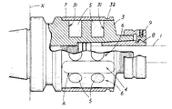
具体的には、本実施例は、図1に図示したように、工具保持体3に工具1を設け、この工具保持体3に内装したスリットにより縮径可能な挟持体8を該工具保持体3に螺合される締付体9の回動により拡縮させて前記工具1を挟持するチャック装置に本発明を適用したものである。尚、焼き嵌めにより工具を固定保持する焼き嵌めタイプのチャック装置にも同様に適用できる。
Specifically, in this embodiment, as shown in FIG. 1, a
尚、工具保持体3は貫通内孔10を有し、先端外周面には前記締付体9の内面の雌ネジ部と螺合する雄ネジ部が設けられている。また、締付体9の内面先端にはボール11を介してリング部材12が回動自在に設けられ、このリング部材12の内面基端には挟持体8の凹溝13に挿入される挿入凸部14が設けられている。また、図中、符号39は貫通内孔10の中央付近に螺合され工具1の基端部に当接して工具1の突出量を設定するための突出量設定部である。
The
また、本実施例においては、シャンク部2はテーパ状に設定しスピンドルに直接取り付ける構成としているが、シャンク部2をストレート形状とし別体のホルダを介してスピンドルに取り付ける構成としても良い。
In the present embodiment, the
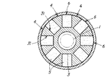
工具保持体3の締付体9が設けられる先端部の後方側にして工作機械Xに装着されるシャンク部2の前方側にして工具保持手段の後方側の外周部には該工具保持体3の軸方向に延設される複数の補強リブ(補強部4)が該工具保持体3の周方向に複数所定間隔(等間隔)で並設されている。この補強リブは工具保持体3の軸芯から放射方向(放射状)に突設され、補強リブ間の空間部の底面は円弧底面に設定されている。尚、補強リブ間の空間部の底面はフラット底面等、他の構成としても良い。また、補強リブは不等間隔で並設する構成としても良い。
The
また、本実施例の補強部4(前記補強リブ及び後記補強肉)の補強とは、振動抑制部を設ける工具保持体3の中央周部を収納凹部6の底面を繋いで得られる工具保持体3の最小径部と同径として、振動抑制部を設けない場合に比し、工具保持体3の剛性を補強する意である。
Further, the reinforcement of the reinforcing portion 4 (the reinforcing rib and the reinforcing meat described later) of the present embodiment is a tool holding body obtained by connecting the central peripheral portion of the
また、この補強リブの工具保持体3の軸方向側両端部は周方向に延設される鍔部15により連結されて、この鍔部15の内面と補強リブの側面とで囲まれる空間が振動減衰材5が収納される収納凹部6に設定されている。振動減衰材5は圧入密着状態で収納凹部6に収納(充填)される。
Further, both ends of the reinforcing rib on the axial direction side of the
振動減衰材5としては本実施例においては高減衰能を有するゴム(粘弾性体)が採用されている。ゴムは硬度が変わることで固有振動数が変化するため、各種使用条件に合わせて所望の硬度のゴムを採用する。また、ゴムに限らず、樹脂等の他の粘弾性体を採用しても良い。また、粘弾性体に限らず、焼砂、鋼球(例えば超鋼製)、鉛若しくは雲母等の直径約50μm〜2mm程度の多数の粒状物を収納凹部6に収納する構成としても良い。尚、多数の粒状物を収納する場合には、互いに摩擦できるようにするため若干の隙間が生じるように充填する。また、鋼球の場合には収納凹部6に共に粘性油を収納する構成としても良い。いずれの場合でも、振動減衰材5の分子同士の摩擦(粘弾性体の場合)若しくは振動減衰材5同士の摩擦(粒状体の場合)に加え、各振動減衰材5と各補強リブとの摩擦により振動エネルギーが熱エネルギーに変換されることで振動エネルギーが減衰せしめられ、工具1の振動は良好に抑制される。
As the
また、本実施例においては、図2に図示したように、補強リブ及び収納凹部6を工具保持体3の周方向等配位置に設けることで、補強リブと振動減衰材5とで構成される振動抑制部を工具保持体3の周部全周にわたって工具保持体3の周方向等配位置に設けている。従って、振動を一層良好に減衰せしめて工具の振動を確実に抑制できることになる。尚、補強部4、収納凹部6、振動抑制部は、工具保持体3の軸芯を挟んで対称位置に設ける構成としても良い。即ち、補強部4、収納凹部6、振動抑制部を工具保持体3の周方向に偏りなく配置し、工具1を回転させて加工を行う際に工具1の偏心等を可及的に抑制できるようにするのが好ましい。
Further, in this embodiment, as shown in FIG. 2, the reinforcing ribs and the storage recesses 6 are provided at the circumferentially equidistant positions of the
また、本実施例においては、振動抑制部を、工具保持体3のシャンク部2の前方側にして工具保持手段の後方側の外周部に設ける構成としているが、シャンク部2に設ける構成としても良い。
In the present embodiment, the vibration suppressing portion is provided on the outer peripheral portion on the rear side of the tool holding means on the front side of the
また、本実施例においては、複数の振動減衰材5を分割状態(分散状態)で設けるため、例えば一若しくは複数の収納凹部6に収納される振動減衰材5として、同一材料に限らず、他の収納凹部6に収納される振動減衰材5と固有振動数の異なる材料を採用することが可能であり、各収納凹部6に夫々固有振動数の異なる振動減衰材5(例えば硬度が異なるゴム)を収納することで、より広い帯域で振動を減衰することが可能となり、工具の振動を一層確実に抑制することが可能となる。
In this embodiment, since the plurality of
また、工具保持体3には振動減衰材5の脱落を防止する抜け止め環体7が被嵌されている。
The
この抜け止め環体7は、図1,2に図示したように工具保持体3の外周面(鍔部15の頂面及び補強リブ4の頂面)の径と略同じ内径に設定したものを圧入嵌合する構成としている。尚、圧入嵌合に限らず、接着剤で接着固定する構成としても良い。従って、抜け止め環体7は、この工具保持体3に対して回転不能な状態で設けられる。
As shown in FIGS. 1 and 2, the retaining
尚、本実施例においては、上述したように工具1としてエンドミルやメタルソーを想定したチャック装置に本発明を適用しているが、例えば図3,4に図示した別例1のように、先端に工具1たるフルバックカッター(フェイスミルカッター)を取り付けるアーバー等に本発明を適用した場合も同様である。図中、符号26はフルバックカッター取り付け用の取付ネジ、27は取付ネジ26が螺合する取付ネジ穴、28は回転阻止部材29と共にフルバックカッターのアーバーに対する回転を阻止するための止めネジ、30は止めネジ28が螺合する止めネジ穴である。
In the present embodiment, as described above, the present invention is applied to a chuck device that assumes an end mill or a metal saw as the
また、図5,6に図示した別例2のように、抜け止め環体7を固定ネジ22により振動減衰材5に直接固定する構成としても良い。この場合、抜け止め環体7の内面と振動減衰材5(ゴム)の頂面とは互いに凹凸係合する凹凸係合面に設定する。また、全ての振動減衰材5に固定ネジ22を螺着せず、図6のように例えば1つおきに螺着して固定する。図中、符号23は真鍮製で振動減衰材5に埋め込まれるものであって内面に固定ネジ22が螺着せしめられる螺着部を有するネジ固定用部材、25はゴムシールである。
5 and 6, the retaining
この別例2においては、抜け止め環体7は工具保持体3とは固定されず、上記凹凸係合面を中心として工具保持体3に対する振動は許容される(揺動可能な状態)。従って、工具保持体3に伝わる振動が振動減衰材5を介して抜け止め環体7へと伝達されると、この抜け止め環体7の質量による慣性から生じる反力によって工具保持体3の振動が相殺されて減衰せしめられることになる(抜け止め環体7が所謂カウンターウエイトのように作用する。)。よって、別例2は一層良好な振動抑制効果が発揮されるものとなる。
In this alternative example 2, the retaining
また、上記実施例においては、補強部4として軸芯から放射方向(放射状)に突設される補強リブを採用し、収納凹部6として工具保持体3の軸方向に延設される溝状の凹部を採用した例について説明しているが、例えば、収納凹部6として前記工具保持体3の軸方向に並設される複数の孔状の凹部31を採用しても良い。即ち、収納凹部6としては長溝状や丸孔状、角孔状等、種々の構成を採用できる。また、1つの孔状の凹部31を収納凹部6に設定しても良い。
Moreover, in the said Example, the reinforcement rib projected radially (radially) from the axial center is employ | adopted as the
具体的には、図7〜13に図示した別例3のように、工具保持体3の軸方向に(一直線上に)並設される複数の孔状の凹部31を夫々収納凹部6とし、この軸方向に並設される複数の孔状の凹部31を複数セット工具保持体3の周方向等配位置に並設する構成とし、各収納凹部6の各孔状の凹部31は、工具保持体3の外周部に穴明け工具等により穿設し、工具保持体3の外周部の各孔状の凹部31を穿設した後の残余の肉部(孔状の凹部31に対して外方に突出する部分)にして(各収納凹部6間で)軸方向に延在する部分(図中A部分)が上記補強リブと同様の機能を発揮する補強肉(補強部4)となる。即ち、各孔状の凹部31を穿設する際には、軸方向に延在する補強肉(補強部4)を残すように穿設する。尚、各収納凹部6同士の間隔は、少なくとも例えば孔状の凹部31の直径(最大径)程度の間隔に設定する。
Specifically, a plurality of hole-shaped
この場合、各収納凹部6の各孔状の凹部31は、工具保持体3の外周部に穴明け工具等により穿設するだけで形成でき、溝状の凹部を形成するのに比べ加工工具を水平方向に移動させる必要がない分だけ加工が容易となる。また、図7〜13においては各孔状の凹部31は重ならないように穿設しているが、一部が重なるように穿設して各孔状の凹部31が連通するように構成しても良い。
In this case, each hole-shaped
各図に基づいて具体的に説明すると、図7,8(別例3−1)は上記実施例と同様の工具保持体3に孔状の凹部31を穿設し、この孔状の凹部31を軸方向に2つ並設して収納凹部6を形成し、この収納凹部6と補強部4となる補強肉とを周方向に交互に8つずつ設けたものである。また、各孔状の凹部31には振動減衰材5としてゴム(粒状物であっても良い)を充填し抜け止め環体7を工具保持体3に圧入嵌合している。また、抜け止め環体7の先端側にはこの抜け止め環体7を引抜くための引抜き工具が係止する係止凹部32が設けられている。
Describing specifically with reference to the drawings, FIGS. 7 and 8 (another example 3-1) are provided with a hole-
また、図9(別例3−2)は、図7,8において振動減衰材5としてゴムだけでなくこのゴム中に鋼球33(または超硬球等の球状体)を各1つずつ埋設した構成であり、この場合、鋼球33の質量による慣性から生じる反力によって工具保持体3の振動が相殺されて減衰せしめられることになる。尚、球状体は1つに限らず複数を同一収納凹部6内に設けても良いが、互いに接触しないように設けるのが好ましい。
9 (Another Example 3-2) is not only rubber as the
また、図10,11(別例3−3)は、図7,8において抜け止め環体7を不要とする構成であり、孔状の凹部31に、振動減衰材5としてのゴムに設けた抜け止め係止部34が係止する係止凹部35を設け、ゴムの抜けを防止する構成である。具体的には、抜け止め係止部34は鍔状に設け、係止凹部35を溝状にぐるりと設けている。この場合、抜け止め環体7が不要となり、それだけコスト安となる。尚、抜け止め係止部34をゴムの周方向に複数の突起を設けて構成し、係止凹部35を前記突起と嵌合する嵌合穴として複数設けても良い。
10 and 11 (another example 3-3) is a configuration that does not require the retaining
また、図12(別例3−4)は、図7,8において抜け止め環体7を圧入嵌合でなく先端側に設けたC字状の抜け止めリング36で係止する構成であり、工具保持体3の中央の径大部分(肉厚部分)の先端側に抜け止めリング36が設けられる溝部37を設け、抜け止め環体7の先端側に前記溝部37に設けられた抜け止めリング36と係止する係止段部38を設けている。尚、内部への切削液の侵入防止のため、シール材や接着剤を併用しても良い。
12 (another example 3-4) is a configuration in which the
また、図13(別例3−5)は、工具保持体3として焼き嵌めによって工具を固定保持するものを採用し、抜け止め環体7の基端側に螺子部39を設け、工具保持体3の外周部にこの螺子部39と螺合する螺合部40を設けて抜け止め環体7を工具保持体3に取り付ける構成である。抜け止め環体7の先端側及び基端側は夫々Oリング41・42により封止される。工具保持体3の中央の径大部分の先端側には先端側のOリング41が配設される先端側配設溝が設けられ、工具保持体3の中央の径大部分の基端側及び抜け止め環体7の基端側には基端側のOリング42が配設される基端側配設溝が夫々設けられる。また、工具保持体3の中央の径大部分は基端側から先端側に向かって徐々に下り傾斜するテーパ部が設けられており、抜け止め環体7も工具保持体3の中央の径大部分の外周にフィットするように中央にテーパ部が設けられている。
FIG. 13 (Another Example 3-5) employs a
以上の別例3の抜け止め環体7を工具保持体3に取り付けるための各構成は、別例3に限らず上記本実施例にも適用可能である。
Each configuration for attaching the retaining
尚、図14は従来例(振動抑制部を有しない以外は本実施例と同様の構成)の振動減衰性の測定結果、図15は本実施例の振動減衰性の測定結果である。これより、本実施例によれば極めて秀れた振動減衰性が発揮されることが確認できた。 FIG. 14 shows the measurement results of the vibration attenuation of the conventional example (the same configuration as that of the present embodiment except that the vibration suppression unit is not provided), and FIG. 15 shows the measurement results of the vibration attenuation of the present example. From this, it was confirmed that according to the present embodiment, extremely excellent vibration damping properties are exhibited.
本発明は上述のように構成したから、工具保持体3のシャンク部2を工作機械のスピンドルに装着し、保持した工具1を回転させて加工を行う際、工具1に生じる振動は工具保持体3を通じて振動抑制部に伝達され、振動減衰材5の分子同士の摩擦に加え、各振動減衰材5と各補強部4との摩擦により振動エネルギーが熱エネルギーに変換されることで振動エネルギーが減衰せしめられ、よって、工具1の振動が抑制されることになる。
Since the present invention is configured as described above, when the
即ち、周方向に分割状態で設けられる振動減衰材5と該振動減衰材5間の補強部4の側面(工具1の回転方向に対して垂直な壁面)との間で相互に摩擦が生じることで、一層良好に振動エネルギーの熱エネルギーへの変換が促進され、補強部4による剛性向上と相俟って、極めて効率的に工具1の振動を抑制することが可能となる。
That is, friction is generated between the
よって、本実施例は、簡易な構成で確実に振動抑制効果を発揮できる極めて実用性に秀れた工具保持体となる。 Therefore, the present embodiment provides a highly practical tool holder that can reliably exhibit a vibration suppressing effect with a simple configuration.
1 工具
2 シャンク部
3 工具保持体
4 補強部
5 振動減衰材
6 収納凹部
7 抜け止め環体
DESCRIPTION OF
Claims (11)
Priority Applications (6)
| Application Number | Priority Date | Filing Date | Title |
|---|---|---|---|
| JP2009298334A JP5451373B2 (en) | 2009-10-30 | 2009-12-28 | Tool holder |
| PCT/JP2010/068316 WO2011052421A1 (en) | 2009-10-30 | 2010-10-19 | Tool holder |
| US13/503,777 US9016988B2 (en) | 2009-10-30 | 2010-10-19 | Tool holder |
| KR1020127013552A KR101646307B1 (en) | 2009-10-30 | 2010-10-19 | Tool holder |
| CN201080049314.0A CN102666005B (en) | 2009-10-30 | 2010-10-19 | Tool holder |
| TW099136693A TWI511832B (en) | 2009-10-30 | 2010-10-27 | Tool holder |
Applications Claiming Priority (3)
| Application Number | Priority Date | Filing Date | Title |
|---|---|---|---|
| JP2009250358 | 2009-10-30 | ||
| JP2009250358 | 2009-10-30 | ||
| JP2009298334A JP5451373B2 (en) | 2009-10-30 | 2009-12-28 | Tool holder |
Publications (3)
| Publication Number | Publication Date |
|---|---|
| JP2011115929A JP2011115929A (en) | 2011-06-16 |
| JP2011115929A5 JP2011115929A5 (en) | 2012-12-13 |
| JP5451373B2 true JP5451373B2 (en) | 2014-03-26 |
Family
ID=43921845
Family Applications (1)
| Application Number | Title | Priority Date | Filing Date |
|---|---|---|---|
| JP2009298334A Active JP5451373B2 (en) | 2009-10-30 | 2009-12-28 | Tool holder |
Country Status (6)
| Country | Link |
|---|---|
| US (1) | US9016988B2 (en) |
| JP (1) | JP5451373B2 (en) |
| KR (1) | KR101646307B1 (en) |
| CN (1) | CN102666005B (en) |
| TW (1) | TWI511832B (en) |
| WO (1) | WO2011052421A1 (en) |
Families Citing this family (30)
| Publication number | Priority date | Publication date | Assignee | Title |
|---|---|---|---|---|
| EP2425928A1 (en) * | 2010-09-06 | 2012-03-07 | WENDT GmbH | Flange for fitting a tool to a spindle |
| JP5966651B2 (en) * | 2012-06-19 | 2016-08-10 | 株式会社ジェイテクト | Spindle device |
| US9061355B2 (en) | 2012-06-29 | 2015-06-23 | Kennametal Inc. | Tool adaptor having an integrated damping device |
| DE102012108098A1 (en) * | 2012-08-31 | 2014-03-06 | Sandvik Intellectual Property Ab | Vibration-damped tool |
| CN102837006B (en) * | 2012-09-04 | 2014-11-05 | 中国人民解放军国防科学技术大学 | Application of viscous-elastic materials in cantilever optical components of ultra-precision turning |
| DE102013103168B3 (en) * | 2012-12-21 | 2014-04-17 | Franz Haimer Maschinenbau Kg | Tool chuck for holding cutter head in machine tool, has clamping section connected with body and provided for clamping tool, and single-piece, molded section comprising cavities in inner area, where cavities form enclave in molded section |
| DE102013101854A1 (en) | 2013-02-05 | 2014-08-07 | Franz Haimer Maschinenbau Kg | Chuck with vibration reduction |
| JP6132019B2 (en) * | 2013-05-17 | 2017-05-24 | 株式会社ニコン | Drive device and robot device |
| JP2015016519A (en) * | 2013-07-10 | 2015-01-29 | 三菱重工業株式会社 | Main spindle unit |
| JP6156642B2 (en) * | 2013-09-17 | 2017-07-05 | トヨタ自動車株式会社 | Tool holder |
| DE102013225472A1 (en) * | 2013-12-10 | 2015-06-11 | Komet Group Gmbh | tooling |
| US9468977B2 (en) * | 2014-02-18 | 2016-10-18 | Kennametal Inc. | Cylindrical grinding process and as-ground part resulting from such process |
| DE112015003078T5 (en) * | 2014-06-30 | 2017-04-06 | Walter Ag | Damper to prevent vibration |
| US9630258B2 (en) | 2014-10-15 | 2017-04-25 | Kennametal Inc | Tool holder assembly with dampening elements |
| EP3009214A1 (en) * | 2014-10-17 | 2016-04-20 | Straumann Holding AG | High-speed tool holder |
| WO2016083421A1 (en) * | 2014-11-27 | 2016-06-02 | MAPAL Fabrik für Präzisionswerkzeuge Dr. Kress KG | Chuck |
| US9586266B2 (en) * | 2015-01-23 | 2017-03-07 | Kennametal Inc. | Toolholder with tunable passive vibration absorber assembly |
| JPWO2016186217A1 (en) * | 2015-05-21 | 2018-03-01 | 京セラ株式会社 | HOLDER, CUTTING TOOL, AND CUTTING PRODUCT MANUFACTURING METHOD USING THE SAME |
| EP3302863B1 (en) * | 2015-06-05 | 2018-12-19 | Gleason Cutting Tools Corporation | Tools with removable information device |
| EP3210703B1 (en) * | 2016-02-29 | 2018-08-15 | Sandvik Intellectual Property AB | A tool body, a tool and a method for manufacturing a tool body |
| CN107972185A (en) * | 2017-12-25 | 2018-05-01 | 沈阳建筑大学 | A kind of knife handle with vibration-damping function |
| US10179367B1 (en) * | 2018-02-07 | 2019-01-15 | Kun-Chi Lo | Damping arbor |
| US10953471B2 (en) * | 2018-04-16 | 2021-03-23 | Iscar, Ltd. | External turning tool having a cutting portion with a transverse elongated damping mechanism |
| CN110159702A (en) * | 2019-06-21 | 2019-08-23 | 浙江向隆机械有限公司 | A kind of external bifrequency semiaxis dynamic vibration absorber |
| CN111113131B (en) * | 2019-12-30 | 2022-09-27 | 湖南中大创远数控装备有限公司 | Main shaft damping mechanism |
| CN111975048A (en) * | 2020-09-14 | 2020-11-24 | 上海名古屋精密工具股份有限公司 | Tool with vibration-damping component |
| CN112247231B (en) * | 2020-10-15 | 2022-11-11 | 航天科工哈尔滨风华有限公司 | Lengthened angle milling head device of three-point positioning supporting structure |
| CN112338623B (en) * | 2020-10-30 | 2022-05-24 | 齐鲁工业大学 | Rigidity self-adjusting fast tool servo device |
| KR102302962B1 (en) * | 2021-04-29 | 2021-09-15 | 권대규 | Processing tool with vibration reducing structure of processing load |
| CN114147510B (en) * | 2021-11-30 | 2022-12-16 | 盐城奥凯明通阀门有限公司 | Production tool for gate valve |
Family Cites Families (25)
| Publication number | Priority date | Publication date | Assignee | Title |
|---|---|---|---|---|
| SE413747B (en) * | 1976-02-04 | 1980-06-23 | Atlas Copco Ab | BEATING TOOLS |
| JPS6176251A (en) * | 1984-09-21 | 1986-04-18 | Agency Of Ind Science & Technol | Vibro-isolating shaft member |
| US5074723A (en) * | 1989-04-13 | 1991-12-24 | Kennametal Inc. | Method and apparatus for balancing a rotary tool assembly |
| JPH03221303A (en) * | 1990-01-23 | 1991-09-30 | Mitsubishi Materials Corp | Boring bar |
| JPH0553839U (en) * | 1991-12-26 | 1993-07-20 | 株式会社大沢製作所 | Rotary tool |
| JPH06155131A (en) * | 1992-11-30 | 1994-06-03 | Honda Motor Co Ltd | Balance adjusting mechanism for milling cutter |
| JPH07227711A (en) * | 1994-02-21 | 1995-08-29 | Mitsubishi Heavy Ind Ltd | End mill |
| JPH07285002A (en) | 1994-04-14 | 1995-10-31 | Toshiba Tungaloy Co Ltd | Vibration control tool for depth machining |
| US5518347A (en) * | 1995-05-23 | 1996-05-21 | Design And Manufacturing Solutions, Inc. | Tuned damping system for suppressing vibrations during machining |
| JP3115815B2 (en) * | 1996-03-13 | 2000-12-11 | 株式会社日研工作所 | Tool holder |
| JPH09253965A (en) * | 1996-03-15 | 1997-09-30 | Nikken Kosakusho:Kk | Tapered cone of tool holder |
| JPH1110414A (en) * | 1997-06-19 | 1999-01-19 | Honda Motor Co Ltd | Boring tool |
| US6280126B1 (en) * | 1999-09-23 | 2001-08-28 | Aesop, Inc. | Damped tool holder and method |
| US6443673B1 (en) * | 2000-01-20 | 2002-09-03 | Kennametal Inc. | Tunable boring bar for suppressing vibrations and method thereof |
| SE522081C2 (en) * | 2000-12-06 | 2004-01-13 | Sandvik Ab | Tools for machining in metallic materials |
| US7028997B2 (en) * | 2001-06-13 | 2006-04-18 | Mitsubishi Materials Corporation | Vibration damping tool |
| JP2004001104A (en) | 2002-04-19 | 2004-01-08 | Yukiwa Seiko Inc | Chuck device and tightener for chuck device |
| US8579562B2 (en) * | 2004-01-16 | 2013-11-12 | Franz Haimer Maschinenbau Kg | Vibration-damped tool holder |
| SE528470C2 (en) * | 2004-02-03 | 2006-11-21 | Mircona Ab | Vibration-damped tool holder with viscoelastic damping material |
| JP2005232729A (en) * | 2004-02-18 | 2005-09-02 | Hayakawa Rubber Co Ltd | Tread for staircase, tread supporting structure, and staircase |
| US7730813B2 (en) * | 2004-07-08 | 2010-06-08 | University Of Florida Research Foundation, Inc. | Variable tuned holder for machine tools |
| TWM275914U (en) * | 2005-03-01 | 2005-09-21 | Power Network Industry Co Ltd | Silent type main spindle locking device |
| NO330162B1 (en) * | 2006-06-28 | 2011-02-28 | Teeness Asa | Container for insertion into a tool holder, a tool holder and a system |
| US8687800B2 (en) * | 2006-08-15 | 2014-04-01 | Alcatel Lucent | Encryption method for message authentication |
| JP2008100332A (en) | 2006-10-20 | 2008-05-01 | Hitachi Tool Engineering Ltd | Vibration isolating tool |
-
2009
- 2009-12-28 JP JP2009298334A patent/JP5451373B2/en active Active
-
2010
- 2010-10-19 US US13/503,777 patent/US9016988B2/en active Active
- 2010-10-19 CN CN201080049314.0A patent/CN102666005B/en active Active
- 2010-10-19 KR KR1020127013552A patent/KR101646307B1/en active IP Right Grant
- 2010-10-19 WO PCT/JP2010/068316 patent/WO2011052421A1/en active Application Filing
- 2010-10-27 TW TW099136693A patent/TWI511832B/en active
Also Published As
| Publication number | Publication date |
|---|---|
| TW201139044A (en) | 2011-11-16 |
| KR101646307B1 (en) | 2016-08-05 |
| WO2011052421A1 (en) | 2011-05-05 |
| JP2011115929A (en) | 2011-06-16 |
| US9016988B2 (en) | 2015-04-28 |
| US20120207560A1 (en) | 2012-08-16 |
| KR20120095937A (en) | 2012-08-29 |
| CN102666005B (en) | 2016-06-22 |
| CN102666005A (en) | 2012-09-12 |
| TWI511832B (en) | 2015-12-11 |
Similar Documents
| Publication | Publication Date | Title |
|---|---|---|
| JP5451373B2 (en) | Tool holder | |
| US8286972B2 (en) | Low-vibration tool holder | |
| RU2519192C2 (en) | Tool holder with damper | |
| JP6446367B2 (en) | Preload type buffer system | |
| CN103154563B (en) | Vibration damping mechanism | |
| US20170197251A1 (en) | Vibration-proof structure of rotating body | |
| US20180281074A1 (en) | Cantilever-supported tuned dynamic absorber | |
| KR101332467B1 (en) | Anti-vibration structure of cutting tool | |
| JP6282210B2 (en) | Tool holder with anti-vibration means | |
| JP2013163964A (en) | Tool holder | |
| BR112016025980B1 (en) | ROD CHISEL AND FIXING ARRANGEMENT | |
| JP6177602B2 (en) | adapter | |
| JP4917954B2 (en) | Turning device | |
| JP2011189447A (en) | Collet chuck | |
| JP7280867B2 (en) | Threaded insert for securing a tool to a tool receiving area, and a tool receiving area containing such a threaded insert | |
| JP2010179447A (en) | Cylindrical drilling tool | |
| JP2010214539A (en) | Chucking device | |
| CN209998386U (en) | cutter bar for machining | |
| US9328787B2 (en) | Rubber stopper | |
| JP2003039214A (en) | Structure for mounting tool holder | |
| JP5802173B2 (en) | Extremely short bit | |
| JP6210886B2 (en) | Tool holder with anti-vibration means | |
| JP2008044035A (en) | Collet chuck | |
| JP2015208817A (en) | Tool holding device of machine tool | |
| KR101535566B1 (en) | Holder for fixing cutting tool |
Legal Events
| Date | Code | Title | Description |
|---|---|---|---|
| A521 | Request for written amendment filed |
Free format text: JAPANESE INTERMEDIATE CODE: A523 Effective date: 20121026 |
|
| A621 | Written request for application examination |
Free format text: JAPANESE INTERMEDIATE CODE: A621 Effective date: 20121026 |
|
| TRDD | Decision of grant or rejection written | ||
| A01 | Written decision to grant a patent or to grant a registration (utility model) |
Free format text: JAPANESE INTERMEDIATE CODE: A01 Effective date: 20131202 |
|
| A61 | First payment of annual fees (during grant procedure) |
Free format text: JAPANESE INTERMEDIATE CODE: A61 Effective date: 20131226 |
|
| R150 | Certificate of patent or registration of utility model |
Free format text: JAPANESE INTERMEDIATE CODE: R150 Ref document number: 5451373 Country of ref document: JP Free format text: JAPANESE INTERMEDIATE CODE: R150 |
|
| R250 | Receipt of annual fees |
Free format text: JAPANESE INTERMEDIATE CODE: R250 |
|
| R250 | Receipt of annual fees |
Free format text: JAPANESE INTERMEDIATE CODE: R250 |
|
| R250 | Receipt of annual fees |
Free format text: JAPANESE INTERMEDIATE CODE: R250 |
|
| R250 | Receipt of annual fees |
Free format text: JAPANESE INTERMEDIATE CODE: R250 |
|
| R250 | Receipt of annual fees |
Free format text: JAPANESE INTERMEDIATE CODE: R250 |
|
| R250 | Receipt of annual fees |
Free format text: JAPANESE INTERMEDIATE CODE: R250 |
|
| R250 | Receipt of annual fees |
Free format text: JAPANESE INTERMEDIATE CODE: R250 |
|
| R250 | Receipt of annual fees |
Free format text: JAPANESE INTERMEDIATE CODE: R250 |