JP5436141B2 - Method for manufacturing ophthalmic imaging apparatus, inspection apparatus, ophthalmic imaging apparatus, and imaging unit - Google Patents
Method for manufacturing ophthalmic imaging apparatus, inspection apparatus, ophthalmic imaging apparatus, and imaging unit Download PDFInfo
- Publication number
- JP5436141B2 JP5436141B2 JP2009241697A JP2009241697A JP5436141B2 JP 5436141 B2 JP5436141 B2 JP 5436141B2 JP 2009241697 A JP2009241697 A JP 2009241697A JP 2009241697 A JP2009241697 A JP 2009241697A JP 5436141 B2 JP5436141 B2 JP 5436141B2
- Authority
- JP
- Japan
- Prior art keywords
- imaging
- optical member
- image
- optical
- light
- Prior art date
- Legal status (The legal status is an assumption and is not a legal conclusion. Google has not performed a legal analysis and makes no representation as to the accuracy of the status listed.)
- Active
Links
Images


Classifications
-
- A—HUMAN NECESSITIES
- A61—MEDICAL OR VETERINARY SCIENCE; HYGIENE
- A61B—DIAGNOSIS; SURGERY; IDENTIFICATION
- A61B3/00—Apparatus for testing the eyes; Instruments for examining the eyes
- A61B3/10—Objective types, i.e. instruments for examining the eyes independent of the patients' perceptions or reactions
- A61B3/14—Arrangements specially adapted for eye photography
-
- Y—GENERAL TAGGING OF NEW TECHNOLOGICAL DEVELOPMENTS; GENERAL TAGGING OF CROSS-SECTIONAL TECHNOLOGIES SPANNING OVER SEVERAL SECTIONS OF THE IPC; TECHNICAL SUBJECTS COVERED BY FORMER USPC CROSS-REFERENCE ART COLLECTIONS [XRACs] AND DIGESTS
- Y10—TECHNICAL SUBJECTS COVERED BY FORMER USPC
- Y10T—TECHNICAL SUBJECTS COVERED BY FORMER US CLASSIFICATION
- Y10T29/00—Metal working
- Y10T29/49—Method of mechanical manufacture
- Y10T29/49826—Assembling or joining
Description
本発明は可視光及び赤外光により被写体を撮影する眼科撮影装置の製造方法、製造に用いる検査装置、製造される眼科撮影装置及び撮影ユニットに関する。 The present invention relates to a manufacturing method of an ophthalmologic imaging apparatus that images a subject with visible light and infrared light, an inspection apparatus used for manufacturing, an ophthalmic imaging apparatus to be manufactured, and an imaging unit.
眼底診断や糖尿病健診等の用途において、眼底を可視光や赤外光で照明して位置調整及びフォーカシングを行い、ストロボ光により眼底の光学像を得る眼底カメラが利用されている。この赤外あるいは可視光による眼底の光学像をデジタルデータとして取得することにより観察及び保存などの幅広い利用が可能となる。特許文献1では、可視光と赤外光とに感度を有するカラーテレビカメラを用い、観察時と撮影時とでテレビカメラ前面に赤外カット特性を有するフィルタを挿脱することで観察と撮影を一撮影手段で行う眼底カメラが開示されている。
In applications such as fundus diagnosis and medical examination for diabetes, a fundus camera is used that illuminates the fundus with visible light or infrared light to perform position adjustment and focusing, and obtains an optical image of the fundus with strobe light. By acquiring the optical image of the fundus oculi by infrared or visible light as digital data, a wide range of usage such as observation and storage becomes possible. In
ここで特許文献1に記載のカラーテレビカメラの代わりに、一般の可視光撮影用のカメラを改変して用いることもできる。カメラに利用されているCCDやCMOS等の撮像素子は元々赤外光にも感度を有しており、赤外カットフィルタにより赤外光が遮断され可視光のみが撮像素子に到達し、結果として可視光の画像が撮影されるに過ぎない。よって、この赤外カットフィルタを除去することで可視光と赤外光の両方による撮像が可能なカメラを得ることができる。
Here, instead of the color television camera described in
一般撮影用のカメラは性能の向上等に伴い早いペースで改良がなされており、色調等の特性が型番ごとに異なる。しかしながら従来の眼底カメラでは、眼底カメラ全体として色調等の特性の調整を行っていたため、眼底カメラ側の光学系のばらつきの影響を受け、撮像素子の特性の調整が困難であった。 Cameras for general photography are improved at a rapid pace as performance is improved, and characteristics such as color tone are different for each model number. However, in the conventional fundus camera, characteristics such as color tone are adjusted as a whole of the fundus camera. Therefore, it is difficult to adjust the characteristics of the image sensor due to the influence of variations in the optical system on the fundus camera side.
本発明の実施形態に係る眼科撮影装置の製造方法は、可視光及び赤外光により被写体の画像を得る撮像部を製造する工程と、赤外光を吸収する光学部材を有する色調の調整手段により前記撮像部の色調を調整する調整工程と、前記光学部材と同一特性のその他の光学部材を備え被検眼の光学像を取得する光学系と、前記調整がされた前記撮像部とを接続する接続工程と、を有することを特徴とする。 The method for manufacturing an ophthalmologic photographing apparatus according to an embodiment of the present invention includes a step of manufacturing an imaging unit that obtains an image of a subject using visible light and infrared light, and a color tone adjusting unit that includes an optical member that absorbs infrared light. An adjustment process for adjusting the color tone of the imaging unit, an optical system that includes another optical member having the same characteristics as the optical member and acquires an optical image of the eye to be inspected, and a connection that connects the adjusted imaging unit And a process.
かかる工程を有することにより、眼底カメラ内に設けられた赤外光を吸収する部材が調整手段に設けられているため、撮像部単体で色調の調整を行った後に眼科撮影装置に接続して眼科撮影装置を得ることができる。これによりカメラの改良による特性の変化に対応して眼科撮影装置を製造することができる。 By having such a process, the member that absorbs infrared light provided in the fundus camera is provided in the adjusting means. Therefore, after adjusting the color tone of the imaging unit alone, it is connected to the ophthalmologic photographing apparatus and the ophthalmologist An imaging device can be obtained. Thus, an ophthalmologic photographing apparatus can be manufactured in response to a change in characteristics due to improvement of the camera.
(実施例1)
本実施例は、可視光撮像装置としてのデジタル一眼レフカメラから赤外光の撮像素子への到達を抑制する特性を除去したものを利用して眼底光学像をデジタルデータに変換する眼底カメラに関するものである。
Example 1
The present embodiment relates to a fundus camera that converts a fundus optical image into digital data using a digital single-lens reflex camera as a visible light imaging device, which has a characteristic that suppresses the arrival of infrared light to an image sensor. It is.
図1は眼科撮影装置の構成図を示している。この眼科撮影装置は、被検眼の眼底の光学像を取得する眼底カメラ1と、この光学像を受光しデジタルデータとして取得する撮像部とからなる。この眼底カメラ1は、被写体である被検眼の眼底の光学像を取得する取得部として機能する。本実施例の眼底カメラは無散瞳眼底カメラである。被写体である被検眼Eに対し前方に配置された眼底カメラ1内には、例えば赤外LEDから成る赤外光を照射する観察光源2から、被検眼Eに対応して配置された対物レンズ3に至るまでの観察照明光学系が設けられている。この観察照明光学系には、観察光源2、ダイクロイックミラー4、リレーレンズ5、孔あきミラー6が順次に配列されている。また、ダイクロイックミラー4の入射方向には、撮影照明光学系としてキセノン管から成る撮影光源7が配置されている。
FIG. 1 shows a configuration diagram of an ophthalmologic photographing apparatus. The ophthalmologic photographing apparatus includes a
孔あきミラー6の後方には撮影光学系として、光軸方向に移動しフォーカスを調整するフォーカスレンズ8が配置されている。このフォーカスレンズ8の光軸の延長上の眼底カメラ1には、デジタル一眼レフカメラ9が着脱可能に取り付けられている。
A
デジタル一眼レフカメラ9は入射した撮影光(赤外光及び可視光)が形成する光学像を電気信号に変えてデジタル画像データを作成する撮像部である。このデジタル画像データは保存され診断や記録に用いられると共に、撮影中に表示させて観察を行うこともできる。この眼底光学像の撮像部としてのデジタル一眼レフカメラ9は、一般の可視光撮影用のデジタル一眼レフカメラの光学系を一部改造して製造されるものであるため、一般撮影用のデジタル一眼レフカメラと同様の外観、形態を有している。
The digital single
なお、ここでいう撮像部としてのデジタル一眼レフカメラ9は必ずしも反射鏡を有している必要はなく、ファインダには撮像素子により得たデジタル画像を表示させるようにしたカメラであっても良い。撮像部としてのデジタル一眼レフカメラ9は被写体の光学像を撮影光として撮像素子9aへと導く対物レンズを着脱可能なレンズ接合部41を有している。レンズ接合部41により眼底カメラと接合する。眼底カメラ1側には、レンズ接合部41と接合可能なカメラ接合部42がある。このカメラ接合部42とレンズ接合部41により、眼底カメラ1により得られる被検眼の眼底の光学像をデジタル一眼レフカメラ9によりデジタルデータとして取得することができる。
Note that the digital single-
デジタル一眼レフカメラ9の内部には、撮影光を受光することにより撮像素子の面上に結像した光学像を電気信号に変換する撮像素子9aが内蔵され、この撮像素子9aの出力はデジタル一眼レフカメラ9内の制御手段9bに接続されている。また、デジタル一眼レフカメラ9の背面には表示部である液晶ディスプレイ9cが設けられ、制御手段9bの出力が接続されている。本実施例のデジタル一眼レフカメラ9は、近赤外の感度を持たせるために撮像素子9a前面に配置される赤外カット特性を有する光学部材を除去している。撮像素子9aは、可視光及び赤外光を受光して画像データを取得することが可能である。詳細については後述する。
The digital single-
また、眼底カメラ1内には制御回路10が設けられ、制御回路10の出力は駆動回路11、12を介して、観察光源2、撮影光源7にそれぞれ接続されている。また、制御回路10はデジタル一眼レフカメラ9内の制御手段9b、及び眼底カメラ1に設けられているレリーズスイッチ19にも接続されている。
In addition, a
また、制御回路10は、駆動回路13を介してアクチュエーター14に接続されている。アクチュエーター14は駆動されると赤外カットフィルタ15を撮影光路内に挿脱する。この赤外カットフィルタ15は、後述するデジタル一眼レフカメラから除去した赤外カット特性と同じ特性を有する。観察時は赤外カットフィルタ15を撮影光路外に退避することでデジタル一眼レフカメラ9による眼底像観察を可能とする。撮影時には赤外カットフィルタ15を撮影光路内に挿入することで、デジタル一眼レフカメラ9および赤外カットフィルタ15により一般の可視光撮影用のデジタル一眼レフカメラと同等の分光特性を得る。
The
また、制御回路10はワンチップマイコンなどで構成されるが、図示されない内蔵または外付けの不揮発メモリに、各種調整値が記録される。後述する赤外カットフィルタ15の特性補償のための調整値もこの不揮発メモリに記憶される。
Further, although the
眼底カメラ1の外部にはコンピュータ20が設けられ、USBやシリアルポートを介してデジタル一眼レフカメラ9の制御手段9b、眼底カメラ1の制御回路10に接続されている。コンピュータ20には眼底カメラ1に接続可能なデジタル一眼レフカメラ9の機種ごとの画像形成のための観察用現像パラメータ及び撮影用現像パラメータが予め記憶されている。これはデジタル一眼レフカメラ9の機種によって、使用される撮像素子9aの特性や撮像素子9aの表面に貼り付けられているカラーフィルタの分光特性が異なり、それに応じて画像処理のパラメータを変更する必要があるためである。
A
レリーズスイッチ19が押されると、制御回路10はデジタル一眼レフカメラ9の制御手段9bに対してレリーズ信号を送信し、これによりデジタル一眼レフカメラ9で撮影動作が行われる。
When the
最近のデジタル一眼レフカメラは、ライブビュー手段としてライブビュー機能を搭載した機種が増加している。ライブビューとはデジタル一眼レフカメラ9に内蔵したクイックリターンミラーを退避させ、シャッタを開状態とし、撮像素子9a上に結像する像を順次に読み出し、表示部としての装置背面の液晶ディスプレイ9cにその画像を連続的に表示する機能である。デジタル一眼レフカメラ9はこのライブビュー機能を有しており、表示部に撮影中の画像を表示することができる。この表示部は、デジタル一眼レフカメラ9のファインダであってもよい。
Recent digital single-lens reflex cameras are increasingly equipped with a live view function as a live view means. With live view, the quick return mirror built in the digital single-
本実施例では、観察時はデジタル一眼レフカメラ9のライブビュー機能を使用する。
In this embodiment, the live view function of the digital single
次に、本実施例のデジタル一眼レフカメラ9に対して赤外カット特性をいかにして除去しているかを図2を使用して説明する。
Next, how the infrared cut characteristic is removed from the digital single-
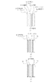
図2は、撮像素子9a前面の光学部材の構成図である。図2(A)は、一般的な可視光撮影用のデジタル一眼レフカメラにおける光学部材の構成の一例を示している。赤外カットフィルタを有しているため、可視光による撮影のみが可能な可視光撮影装置として機能するものである。
FIG. 2 is a configuration diagram of an optical member on the front surface of the
撮像素子9aの素子上には画素ごとにRGBいずれかの色が来るようにカラーフィルタ21がオンチップ上に固定されている。各色の配列はBayer配列に従う。
撮像素子9aの前面には、カバーガラスを兼ねた第一の水晶板22が固定されている。撮像素子9a、所定の波長の光のみを透過するカラーフィルタ21、第一の水晶板22は一体化されている。
これらの前面には、1/4波長板である位相差を与える位相板23,赤外光の撮像素子9aへの到達を抑制する赤外吸収ガラス24が配置され、更に最前面には第二の水晶板25が配される。第二の水晶板25の前面には赤外光を反射する赤外反射コーティング26が施されている。説明のため、図2では厚く見えるが、実際の赤外反射コーティング26は1μm以下と薄い。
The
A first crystal plate 22 that also serves as a cover glass is fixed to the front surface of the
A
第一の水晶板22、位相板23、第二の水晶板25は高周波成分によるモアレを防ぐ光学ローパスフィルタを構成している。また、赤外光を抑制する赤外吸収ガラス24、および赤外反射コーティング26によって、赤外カット特性を呈しているため、赤外光が撮像素子に到達しない。これにより一般のデジタル一眼レフカメラは可視光撮像装置として機能する。
撮像素子9aはCMOSやCCDなどの種別があるが、いずれもシリコン半導体であり、フィルタがない単体状態では可視光だけでなく近赤外光にも感度を持つ。また、カラーフィルタ21に使われる色素は少なくともR(赤色光を透過するフィルタ)については一般的に近赤外光を透過する。そのため、カラーフィルタを有する撮像素子9aは赤外光に感度を有することとなる。赤外光をカットまたは抑制する特性は前述のように赤外吸収ガラス24、及び赤外反射コーティング26によって得られている。
The first quartz plate 22, the
The
図2(B)は、本実施例のデジタル一眼レフカメラ9における構成を示している。赤外光をカットまたは抑制する特性を除去するために、赤外吸収ガラス24、および赤外反射コーティング26を無くし、代わりに赤外吸収ガラス24の光路長分を補償するためのダミーガラス27を配している。ダミーガラス27の厚みは、赤外吸収ガラス24の厚みとほぼ等しくてかまわない。また、赤外反射コーティング26の替わりに近赤外光を透過する反射防止コーティング28を第二の水晶板25前面に施している。これにより赤外光に感度を有する撮像素子9aに赤外光が到達することなり、撮像素子9aにより赤外光の光学像を画像データとして得ることができる。
FIG. 2B shows a configuration of the digital single-
このようにダミーガラス27は第二の水晶板25よりも撮像素子9aに近い位置に置くことが好ましい。これは、第一の水晶板22、第二の水晶板25が位相板23と共にローパスフィルタを構成しており、波長帯域が狭められた光束に対して光路長を補償する方が、その光学部材の選択、設計及び検査が容易になるという効果がある。
Thus, the
図2(C)は、光路長補償の別の例を示している。図2(B)のダミーガラス27の替わりに位相板の厚みを赤外吸収ガラス24の光路長分増やした位相板29としたものである。(B)の位相板23とダミーガラス27の二部品だったものが一部品で済むために製造が容易というメリットがある。
FIG. 2C shows another example of optical path length compensation. Instead of the
上記の光路長補償は、デジタル一眼レフカメラ9外の眼底カメラ1における光学系によって行うことが可能なので必ずしも必須ではない。しかし撮像素子前面で光路長補償することで一般的デジタル一眼レフカメラの調整工具を流用することが可能なのでこうすることが望ましい。このように、赤外吸収ガラス24の代わりに、撮影光路長を変更させる量を同一とするダミーガラス27を設けることで、デジタル一眼レフカメラ9内での撮影光の光路長が通常の可視光撮影用のデジタル一眼レフカメラと同一になる。これによりピント調整の工程や、その他光路長により検査及び調整の結果が異なるような工程を共通化することができるという効果がある。
The above optical path length compensation is not necessarily required because it can be performed by the optical system in the
更には、赤外吸収ガラス24の代わりにそれと撮影光の光路長を変化させる量が同一となるように位相板23の厚みを定め、デジタル一眼レフカメラ9内の撮影光の光路長を通常の可視光撮影用のデジタル一眼レフカメラと同一にしている。これにより部品点数を減らしつつ工程を共通化することができるという効果がある。
Further, instead of the infrared absorbing
このような光路長補償は、ダミーガラス27等の光学部材を設けなくとも、撮像素子9aやその他の光学部材等の配設位置を変えることでも実現は可能である。部材を設けないで光路長を補償する場合には部品点数を減らすことができるため、コストの低減に有効である。一方で、光学部材を設けることにより光路長を補償する場合にも大きなメリットがある。それは、既存のデジタル一眼レフカメラを一部改変して本実施例に係るデジタル一眼レフカメラを設計及び製造する場合である。一般に装置内部は大型化を極力避けるため部品の配置が最適化されており、部材の位置を変えて設計する事は容易ではない。また、製造の際には既存の工程と別に多くの製造、検査または調整の工程を用意する必要が生じてしまう。これは部品点数を変えるよりも大きなコスト上のデメリットとなり得る。ここで既存の装置において赤外吸収ガラス24が配設される位置に赤外吸収ガラス24の光路長を補償する光学部材を配設すれば、既存の部品配置構成を有効利用し、コストアップを極力避けた設計とすることができる。光学部材を設けることによる光路長の補償にもこのような点でメリットがあると言える。
Such optical path length compensation can also be realized by changing the arrangement position of the
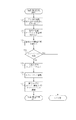
次に本実施例における各装置の動作について、図3から図5のフローチャートを用いて説明する。まず、図3を用いて眼底カメラ1の動作の流れを説明する。電源が投入され動作がスタートすると、ステップS1において眼底カメラ1の内部状態の初期化等を行う。次にステップS2で、スイッチ操作が行われるのを待ち、スイッチ操作がされるまでこのステップS2を繰り返し、スイッチ操作が行われるとステップS3に進み、操作されたスイッチを識別する。
Next, the operation of each device in the present embodiment will be described with reference to the flowcharts of FIGS. First, the operation flow of the
続いて、ステップS4で操作されたスイッチがレリーズスイッチ19であるか否かを判断し、レリーズスイッチ19の操作ではないと判断された場合にはステップS5に進み、スイッチ操作に応じた眼底カメラ1の内部処理を行う。そして、ステップS2に戻る。
Subsequently, it is determined whether or not the switch operated in step S4 is the
またステップS4において、レリーズスイッチ19が操作されたと判断された場合には、ステップS6に進み、駆動回路13およびアクチュエーター14を介して赤外カットフィルタ15を撮影光路内に挿入する。そして、ステップS7に進み、レリーズ信号をデジタル一眼レフカメラ9の制御手段9bに送信する。次に、ステップS8において、デジタル一眼レフカメラ9の撮影動作のシャッタ開タイミングと撮影光源7の発光タイミングを合わせるために、所定時間の経過を待つ。そして、所定時間経過するとステップS9に進み、撮影光源7を発光させて撮像を行う。そしてステップS10において再び駆動回路13およびアクチュエーター14を介して赤外カットフィルタ15を撮影光路より退避させる。そして、ステップS11において撮影光源7のストロボの再充電を行い、ステップS2に戻る。
If it is determined in step S4 that the
以上のように、デジタル一眼レフカメラ9第一の光学部材である赤外吸収ガラス24の代わりに、第二の光学部材であるダミーガラス27または位相板29を設ける。その上で、第一の光学部材と同一特性(分光特性)である第三の光学部材としての赤外カットフィルタ37を眼底カメラ内に設けることとしている。これにより赤外光による観察画像の撮影を行うか、可視光による撮影を行うかで赤外カットフィルタ15を光路に対して進退させて、赤外カットフィルタを除去したデジタル一眼レフカメラによる撮影が可能となる。また、眼底カメラ内に配設された赤外カットフィルタを、デジタル一眼レフカメラ9から除去した赤外吸収ガラスと同一の分光特性とすることにより、通常の可視光撮影用のデジタル一眼レフカメラと同一の分光特性を得ることができる。これにより、通常の可視光撮影用のデジタル一眼レフカメラの設定を利用した画像処理や撮影が可能となる。
As described above, the
次に図4を用いてコンピュータ20の動作の流れを説明する。コンピュータ20の電源が投入されると、まずステップS12において、デジタル一眼レフカメラ9に対して機種名の問い合わせる通知を送信する。ステップS13において要求した機種名の回答を待ち、コンピュータ20が回答を受信した場合にはステップS14に進み、ステップS13で得られた機種名に応じた観察用の現像パラメータをコンピュータ20内から読み出し、デジタル一眼レフカメラ9に送信する。これにより、デジタル一眼レフカメラ9に観察用現像パラメータをセットする。
Next, the operation flow of the
次にステップS15で、ステップS14と同様に機種名に応じた撮影用の現像パラメータをコンピュータ20内から読み出し、デジタル一眼レフカメラ9に送信し、デジタル一眼レフカメラ9では撮影用現像パラメータをセットする。
Next, in step S15, as in step S14, shooting development parameters corresponding to the model name are read from the
なお、ステップS14、S15において現像パラメータを切換えることにより、観察光源2が赤外LED、撮影光源7がキセノン管と光源が異なっても、それぞれの観察光源2、撮影光源7に最適な観察、撮影を行うことができる。 Note that by switching the development parameters in steps S14 and S15, even when the observation light source 2 is an infrared LED and the imaging light source 7 is different from the xenon tube, the observation and imaging optimum for each observation light source 2 and imaging light source 7 are performed. It can be performed.
ステップS16において、デジタル一眼レフカメラ9に対してライブビューを開始し、本発明に関する動作を終了する。
In step S16, live view is started for the digital single-
このようにコンピュータ20が眼底カメラ1とデジタル一眼レフカメラ9の間の通信を行い、機種名及びそれに応じた画像処理の設定情報を受渡すことで、接続されるデジタル一眼レフカメラに応じた画像処理が可能となる。特に、一般消費者用のカメラとは異なり、眼底カメラやそれに接続されるデジタルカメラ煮より得られる画像は医学的な診断に用いられるために、カメラの特性によって画像の色合いやコントラストが変わることは問題である。また、眼底カメラ1に付属するコンピュータ20側に画像処理の設定情報を格納させることにより、異なる種類のデジタルカメラが接続された際にも、眼底カメラ1の特性に合わせた画像処理を可能にするという効果がある。
In this way, the
次に図5に基づいてデジタル一眼レフカメラ9の動作を説明する。電源が投入されるとまずステップS21において、図4のステップS12で説明したコンピュータ20により機種名の要求または確認を待つ。機種名の要求または確認があった場合には、ステップS22に進み要求に応じて機種名を回答する。なお、ここでは機種名自体でなくとも、後述する画像処理の設定情報を特定するために必要な情報であれば良い。
Next, the operation of the digital single-
続いてステップS23において、コンピュータ20からデジタル一眼レフカメラ9の機種に該当する観察用現像パラメータを受信するのを待つ。そして、観察用現像パラメータを受信すると、ステップS24においてこの観察用現像パラメータを制御手段9bの内部のメモリにセットする。
Subsequently, in step S23, the process waits for reception of an observation development parameter corresponding to the model of the digital single-
次に、ステップS25において、コンピュータ20からデジタル一眼レフカメラ9の機種に該当する撮影用現像パラメータを受信するのを待ち、受信するとステップS26において、この撮影用現像パラメータを制御手段9bのメモリにセットする。
Next, in step S25, it waits for reception of the shooting development parameters corresponding to the model of the digital single-
次にステップS27に進み、図4のステップS16においてコンピュータ20からライブビュー開始の指令を受信するのを待ち、指令を受信すると、ステップS28でライブビュー動作を開始し、デジタル一眼レフカメラ9を観察手段として用いる。つまり、観察光源2を発光し、デジタル一眼レフカメラ9内のクイックリターンミラーを退避させて、シャッタを開き、撮像素子9a上に結像された眼底画像を順次に読み出し、観察用現像パラメータを用いて画像を現像し、液晶ディスプレイ9c上に表示を行う。この動作をライブビューを実行している間は続ける。
Next, the process proceeds to step S27 and waits for reception of a live view start command from the
そして、ステップS29に進み、図3のステップS7による眼底カメラ1からレリーズ信号を受信したか否かを確認する。ステップS29において、レリーズ信号を受信できなかった場合にはステップS29に戻る。また、レリーズ信号を受信した場合にはステップS30に進み、パラメータ切換手段により制御手段9bのメモリにセットされている撮影用現像パラメータを現像パラメータとしてセットする。
Then, the process proceeds to step S29, and it is confirmed whether or not a release signal is received from the
そして、ステップS31に進んで静止画の撮影動作に入り、所定時間、撮像素子9a上に静止画用の蓄積を行う。蓄積を行っている過程で、図3のステップS9で撮影光源7が発光し撮影が行われる。そして、静止画像の読み出しを行い、撮影用現像パラメータを使用して静止画の現像が行われ、デジタル一眼レフカメラ9内の図示しない記憶メディアに画像を記録する。或いは、接続されているコンピュータ20に静止画像を送るようにしてもよい。
Then, the process proceeds to step S31 to enter a still image photographing operation, and accumulation for a still image is performed on the
静止画撮影が終了するとステップS32に進み、再び観察用現像パラメータを現像パラメータとしてセットし、ステップS33でライブビューを再開した後にステップS29に戻る。 When the still image shooting ends, the process proceeds to step S32, the observation development parameter is set again as the development parameter, the live view is resumed in step S33, and then the process returns to step S29.
このように、眼底カメラ1のコンピュータ20からの設定情報に応じて画像の表示及び撮影を行うことができるため、通常のデジタルカメラと同様の操作によって眼底画像の観察及び撮影が可能となる。また、レリーズスイッチが押下されたことに応じて観察用の赤外光画像を調整するための画像処理の設定から、可視光画像を調整するための画像処理の設定へと切り換えることにより、ユーザに設定変更の操作を強いることなく夫々の画像に応じた処理が可能となる。
As described above, since the image can be displayed and photographed according to the setting information from the
以下では、図6により本実施例のデジタル一眼レフカメラ9のカラーバランスに関する調整を行う工具とその調整について説明する。本実施例におけるデジタル一眼レフカメラ9は赤外カット特性を有していないため、分光特性が通常の可視光撮影用のデジタル一眼レフカメラと異なっている。そのために通常のデジタル一眼レフカメラに対して用いられるカラーバランス調整の工程をそのままでは利用することが出来ない。眼底カメラ用デジタル一眼レフカメラの専用のカラーバランス調整工具を製作し利用することは非常なコストアップとなる。そこで以下で説明するようにして通常のデジタル一眼レフカメラの調整工具を流用する。なお、カラーバランスの調整には光路長の違いによる影響はない。
Hereinafter, a tool for adjusting the color balance of the digital single-
本実施例のデジタル一眼レフカメラのカラーバランス調整工程を図6を用いて説明する。図6には調整工具にデジタル一眼レフカメラ9を設置した際の構成図である。31はデジタル一眼レフカメラの調整工具である。工具用レンズ36が内蔵されており、デジタル一眼レフカメラ9をレンズ接合部41と工具用レンズ36のレンズマウント部を介して取り付けることが出来る。
The color balance adjustment process of the digital single-lens reflex camera of the present embodiment will be described with reference to FIG. FIG. 6 is a configuration diagram when the digital single-
調整工具31の内部には工具用レンズ36の光軸上にカラーバランス調整用のカラーチャート32が配置されている。デジタル一眼レフカメラ9が撮影対象とするものである。
調整工具31内には調整工程を制御するための制御回路33が内蔵されている。制御回路33の出力は、駆動回路34を介して、撮影対象であるカラーチャート32を照明する照明用光源35に接続されている。
A
A
また、制御回路33は、デジタル一眼レフカメラ9のUSB端子や調整工程専用端子と接続されている。
Further, the
37は赤外カットフィルタで、工具用レンズ36の前面に配置される。赤外カットフィルタ37は、眼底カメラに内蔵される赤外カットフィルタ15と同一特性を示す光学フィルタである。すなわち、デジタル一眼レフカメラ9で除去されている赤外カット特性と同一特性を示す。
この赤外カットフィルタ37の配置は、ユーザによる手動により行ってもよい。この場合には、調整工具31に赤外カットフィルタ37を光路内に挿入するための挿入部としての挿入口を設けユーザが出し入れできるようにしても良い。また、自動的に赤外カットフィルタ37を光路内に挿入してもよい。この場合には、赤外カットフィルタ37を挿入する挿入部としての駆動機構と連結しておく。そして調整対象が通常の可視光撮像装置としてのデジタル一眼レフカメラか、本実施例に係るデジタル一眼レフカメラ9であるか否かを示す情報の入力に応じて挿入部としての駆動機構を起動し、光路内に挿入または光路から退避させることとしても良い。または、挿入または退避のどちらか一方のみ自動的に行うこととしても良い。要は、赤外カットフィルタ37を光路内に挿入する挿入部として機能する構成を有していれば良い。
The arrangement of the
通常の可視光撮影装置としてのデジタル一眼レフカメラを調整する場合は、赤外カットフィルタ37は配置されない。
When adjusting a digital single-lens reflex camera as a normal visible light photographing apparatus, the
本実施例のデジタル一眼レフカメラ9を調整する際には赤外カットフィルタ37を調整工具31内に配置し調整工程を行う。
When adjusting the digital single-
以下、本実施例に係るデジタル一眼レフカメラ9の製造工程を以下図7に従って説明する。
Hereinafter, the manufacturing process of the digital single-
ステップS71までの工程では、周知のデジタル一眼レフカメラの製造工程に従い、筐体内に各部品を組み込んでいく。部品の組み込みは、製造機械を用いて行っても、作業者が手で組み込みを行っても良い。ステップS71において、先述の厚みを増やした位相板29を組み込む。
In the process up to step S71, each component is incorporated into the housing in accordance with a known digital SLR camera manufacturing process. The parts may be assembled using a manufacturing machine or manually by an operator. In step S71, the
ここまでの工程としては、赤外吸収ガラス24を配設する工程と並行して行われる別の製造ラインまたは製造工程を設け、赤外吸収ガラス24を配設する筐体内の位置にダミーガラス27を設けることとしてもよい。また、位相板を設ける工程を2つ用意し、一方は通常の可視光撮像用の位相板23を配設する工程とし、もう一方は本実施例に係るカメラ用に厚みの異なる位相板を配設する工程としても良い。この場合には、例えばベルトコンベアを用いたラインによる生産ではない場合、ロットごとの工程の改変が容易な場合には、無駄な工程を減らすことができるため有用である。
As a process so far, another manufacturing line or manufacturing process performed in parallel with the process of disposing the infrared absorbing
ステップS72では、装置の筐体内に近赤外光を透過する反射防止コーティング28を施した第二の水晶板25を組み込む。組み込む位置は、図2にて述べたとおり通常のデジタル一眼レフカメラにおいて第二の水晶板25が組み込まれる位置と同じ位置であり、ただコーティングが異なる部品を組み込む工程である。
In step S72, the
その他、必要な部品を筐体内に組み込む(ステップS73)。この工程については周知のデジタル一眼レフカメラの製造方法と同様である。 In addition, necessary parts are incorporated into the housing (step S73). About this process, it is the same as that of the manufacturing method of the known digital single-lens reflex camera.
ここまでの工程で部品の組み込みは終了し、以後は検査及び必要な情報の格納作業となる。 The assembly of parts is completed by the steps so far, and thereafter, inspection and storage of necessary information are performed.
ステップS74では、フランジバック検査を行う。このフランジバックとはレンズ交換式のカメラにおいて、レンズマウントのマウント面から、撮像素子面までの光路長のことである。通常このフランジバックの長さはレンズマウントの規格によってフランジバックの長さは厳密に決まっている。フランジバックの長さには高い精度が求められているため、一般のデジタル一眼レフカメラと本実施例に係るデジタル一眼レフカメラ9のフランジバックを厳密に調整する必要がある。このフランジバック検査を周知の方法に基づき、所定の調整器を利用して行う。フランジバック検査の結果要求仕様を満たしていると判定された場合には、要求仕様を満たしていないと判定された場合にはNG判定がなされる。
In step S74, a flange back inspection is performed. This flange back is the optical path length from the mount surface of the lens mount to the image sensor surface in the interchangeable lens camera. Normally, the length of the flange back is strictly determined by the lens mount standard. Since high accuracy is required for the length of the flange back, it is necessary to strictly adjust the flange back of the general digital single lens reflex camera and the digital single
ステップS75にて、調整工程の準備を行う。先述の調整工具31において赤外カットフィルタ37を撮影光路に挿入する。挿入は、調整工具31にて不図示の駆動機構によって行ってもよく、また予め設けられた挿入口に作業者が手動で赤外カットフィルタを挿入しても良い。また、ここで調整工具31にデジタル一眼レフカメラ9を接続する。接続した際に、制御回路33を介してデジタル一眼レフカメラ9の識別情報を調整工具31に通知する。ここでいう識別情報とは、接続するデジタル一眼レフカメラ9の機能に関する情報であり、カラーバランスの調整に際して必要な機能を特定するために十分な情報である。この識別情報の通知により、接続したカメラに応じて調整の基準値を変更する。このように機種の識別情報を通知するようにしたことにより、設定情報を準備すれば、複数種類のカメラの調整を一台の調整工具31で実行することが可能となる上、製造のロットが変わるたびに手動で基準値を変更する手間を省くことができる。なお、この基準値は、作業者が機種毎に予め準備して置く必要があるが、一度基準値を定めてしまえばその後は同一型番の装置については再び定める必要はない。
In step S75, the adjustment process is prepared. In the
ステップS76にて、調整工具31により色調(カラーバランス)の調整を行う。ここでのカラーバランスは、赤外光及び可視光を撮影光として画像データを撮影することができるデジタル一眼レフカメラ9について、可視光で撮影して得られる画像のカラーバランスを調整する工程である。調整工具31は眼底カメラ1の赤外カットフィルタ15と同一特性の赤外カットフィルタ37を有しているため、眼底カメラ1と接続して可視光撮影した際の画像における色調を調整することができる。調整工具31から調整に必要なゲインの調整値を得て、デジタル一眼レフカメラ9内の不図示の記憶部に記憶しておく。詳細については後述する。
In step S76, the
ステップS77において、カラーバランスの調整が済んだデジタル一眼レフカメラ9を眼底カメラ1に取り付ける。この際に、ゲインの調整値を眼底カメラ1に付属するコンピュータ20内の記憶部に格納する。ここで眼底カメラ1内に調整値を記憶しておくのは、デジタル一眼レフカメラ9により得られた画像に対して眼底カメラ1側のコンピュータ20内で画像処理や調整を行うためである。この設定値によって眼底カメラ1側で必要な色調の調整を行う。以上で製造工程が終了する。
In step S77, the digital single-
このように、デジタル一眼レフカメラ9単体で色調の調整を行った後、眼底カメラ1と接続するため、眼底カメラ1の光学系の影響を受けずにデジタル一眼レフカメラ9の撮像素子及び光学系の特性に応じた調整を高精度に行うことができる。また、調整工具31には眼底カメラ1と同一特性の赤外カットフィルタを有しているため、眼底カメラ1との接続後のカラーバランス調整を省略することができる。
In this way, after adjusting the color tone of the digital single-
ステップS76のカラーバランスを調整する工程における制御回路33の動作の詳細を図8のフローチャートを用いて説明する。
Details of the operation of the
デジタル一眼レフカメラ9を調整工具31に取り付け、調整工程を開始すると図8のフローが開始される。
When the digital single-
制御回路33は駆動回路34を介して、照明用光源35を点灯させる(ステップS41)。次に、制御回路33は、デジタル一眼レフカメラの撮影動作を行い撮影対象であるカラーチャート32を撮影する(ステップS42)。
The
次に、制御回路33は、撮影された画像を読み出し(ステップS43)、撮影したカラーチャート部分のRGBの値からカラーバランスを演算する(ステップS44)。
カラーバランスの値が所定の範囲内であれば(ステップS45)、調整工程を終了する。カラーバランスが所定範囲外の場合は、所定範囲内になるようなRGB各色のゲイン値を演算し、この値を調整値としてデジタル一眼レフカメラ9に対して送信し、ゲイン設定を行う(ステップS46)。
Next, the
If the color balance value is within the predetermined range (step S45), the adjustment process is terminated. When the color balance is outside the predetermined range, the gain values of the respective RGB colors are calculated so as to be within the predetermined range, and these values are transmitted as adjustment values to the digital single
そして、ステップS42に戻って、カラーバランスが所定範囲内に入るまでステップS42からステップS46を繰り返すことでカラーバランス調整を行う。 Then, returning to step S42, color balance adjustment is performed by repeating steps S42 to S46 until the color balance falls within a predetermined range.
以上によりデジタル一眼レフカメラのカラーバランス調整が可能となる。デジタル一眼レフカメラ9と赤外カットフィルタ37を組み合わせることで通常のデジタル一眼レフカメラと同一分光特性となり、専用の調整工具を用いずにデジタル一眼レフカメラ9の調整を行うことが可能となる。また調整時の所定値についても通常のデジタル一眼レフと同一でかまわない。
As described above, the color balance of the digital single-lens reflex camera can be adjusted. By combining the digital single-
なお、本実施例の説明では赤外カットフィルタ37は、工具用レンズ36前面に配置したが、これは撮影光路内の任意の位置に配することができる。例えば、工具用レンズ36とデジタル一眼レフカメラ9の間に入れるようにしても良いし、また照明用光源35の前面に配するようにしても良い。
In the description of the present embodiment, the
次に、撮影時のコンピュータ20の動作について図10を用いて説明する。
Next, the operation of the
まず、撮影前にコンピュータ20は眼底カメラ1内に記憶されているカラーバランスオフセット値を読み出す(ステップS61)。
First, before photographing, the
次にステップS62において撮影が行われるまで待ち、撮影光を撮像素子9aが受光する撮影が行われたならば、ステップS63に進み、撮影した画像をコンピュータ20がデジタル一眼レフカメラ9から読み出す。
Next, in step S62, the process waits until shooting is performed. If shooting is performed in which the
次に読み出された画像に対し、ステップS61で読み出されたカラーバランスオフセット値に基づいて標準的なカラーバランスに戻すようにステップS64において画像色補正が行われる。このように、色調の制御を眼底カメラ1のコンピュータ20で統合的に行うことにより、デジタル一眼レフカメラ9を接続した眼底カメラ1により得られる画像データのカラーバランスを適切かつ容易に調整できる。
Next, in step S64, image color correction is performed on the read image so as to return to the standard color balance based on the color balance offset value read in step S61. As described above, the color balance of the image data obtained by the
(実施例2)
実施例2では、実施例1と装置の構成および処理は同様であるが、調整工具31の構成と一部の調整工程が異なっている。眼底カメラ1では赤外カットフィルタ以外にもエキサイタフィルタ等の色調に影響を与えるフィルタが用意されている。このエキサイタフィルタとは、特定の範囲の波長を有する光を選択的に透過するものである。眼底の撮影方法として血管に蛍光材を入れ、この蛍光材を励起する光をエキサイタフィルタにより作り出して蛍光材を励起し、その光により血管の撮影するという撮影方法がある。この際には、照射光を選択的に透過するエキサイタフィルタと、眼底からの反射光を選択的に透過する濾過フィルタを通った光により光学像を形成する。
(Example 2)
In the second embodiment, the configuration and processing of the apparatus are the same as those in the first embodiment, but the configuration of the
そこで、それらエキサイタフィルタを透過した照明光の眼底における反射光を、濾過フィルタを通して取得して撮影した際のホワイトバランス等の調整をする必要がある。そのために、本実施例では、調整工具31の撮影光路に赤外カットフィルタ37の代わりに、または赤外カットフィルタ37と共に不図示のエキサイタフィルタ及び不図示の濾過フィルタを挿入することができる。これらフィルタの挿入には、先述の挿入口によりユーザが手動で挿入することができるようにしても、駆動機構を有する挿入部が自動で挿入することができるようにしてもよい。調整の工程については先述の図8に示されるフローチャートに従い調整が行われるが、用いられるフィルタが異なっており、赤外カットフィルタによる調整値とは別のメモリ領域に格納される。
Therefore, it is necessary to adjust the white balance or the like when the reflected light from the fundus of the illumination light transmitted through the exciter filters is acquired through the filter and photographed. Therefore, in this embodiment, an exciter filter (not shown) and a filter (not shown) can be inserted in the imaging optical path of the
このように、赤外カットフィルタによる色調への影響だけでなく、エキサイタフィルタによる色調への影響も補正をすることができるため、眼底カメラによる画像データのカラーバランスをより適切に調整することができる。 Thus, not only the influence on the color tone by the infrared cut filter but also the influence on the color tone by the exciter filter can be corrected, so that the color balance of the image data by the fundus camera can be adjusted more appropriately. .
なお、エキサイタフィルタに限らず、眼底カメラ内の光学系に含まれる色調への影響を与えるその他のフィルタを調整工具31に挿入できることとしてもよい。
Not only the exciter filter but also other filters that affect the color tone included in the optical system in the fundus camera may be inserted into the
更に、赤外カットフィルタ37を挿入してカラーチャート32を撮影して調整をする場合と、エキサイタフィルタを挿入して調整をする場合とで、デジタル一眼レフカメラ9の撮像素子9aの現像パラメータを変更してもよい。ここでいう現像パラメータとは、R,G,B3つのカラーフィルタを通して得た信号の強度の線型結合により輝度値を算出する際の夫々の信号に乗ずる係数値である。
この場合、赤外カットフィルタを用いて撮影する際には一般の可視光撮影用のデジタル一眼レフカメラ9と同様の係数値でよいが、エキサイタフィルタを挿入した際にはこの係数値を変える。これは、眼底カメラ1にて蛍光材による血管の蛍光撮影を行った場合に、現像パラメータを変更することがあるためである。これにより、蛍光撮影時のカラーバランスを正確に調整することができる。
Furthermore, the development parameters of the
In this case, when photographing using an infrared cut filter, a coefficient value similar to that of a general digital single-
(その他の実施例)
実施例1と利用される眼底カメラ1及びデジタル一眼レフカメラ9は同じであるが、調整の目的及び方法が異なっている。本実施例では、デジタル一眼レフカメラ9単体での調整に加えて眼底カメラ1と接続した状態でもカラーバランスの調整を行う。これにより、予め撮像素子の調整がなされているため、眼底カメラ1内の光学系による影響を低減してより高精度に色調の調整を行うことができる。
(Other examples)
The
また、眼底カメラ内の赤外カットフィルタ15について、製造ロットのばらつき等の影響により、本来同一の分光特性であるはずの調整工程で用いる赤外カットフィルタ37と分光特性のずれを生じることがある。これは次のようにして補正することが可能である。デジタル一眼レフカメラ9を接続した眼底カメラ1全体でのカラーバランス調整を行う際のコンピュータ20の動作について図9を用いて説明する。
Further, the
眼底カメラ1の調整工程においては、前記調整用のカラーチャート32に相当するものとして、図1に示す被検眼Eの位置に人工の模型眼に調整用カラーチャートを貼り付けたものを配する。撮影対象としてのカラーチャートが貼り付けられた人工模型眼を設置し、また先に説明した調整を行ったデジタル一眼レフカメラ9を眼底カメラ1に装着する。その後眼底カメラ1とデジタル一眼レフカメラ9およびコンピュータ20の接続を行った状態で、図8の調整動作を開始する。
In the adjustment process of the
まずステップS51において、コンピュータ20は、眼底カメラ1、デジタル一眼レフカメラ9に指令を出し、撮影動作を行う。
First, in step S51, the
このとき、図3で説明したフローチャートに従い、撮影は赤外カットフィルタ15を挿入した状態で撮影が行われる。
At this time, according to the flowchart described with reference to FIG. 3, imaging is performed with the
次にステップS52に進み、撮影した画像をコンピュータ20がデジタル一眼レフカメラ9から読み出す。
In step S52, the
次にステップS53に進み、RGB各色のカラーバランスの演算が行われる。
標準値からカラーバランスがどれだけずれているかを示すカラーバランスオフセット値がステップS54で眼底カメラ1に送信され、眼底カメラ1は制御回路10内またはその外部の不図示の不揮発メモリに記憶する。以上で調整工程は終了する。
これにより、赤外カットフィルタ15の製造バラツキによる誤差を補正することができる。また、デジタル一眼レフカメラ9単体と、眼底カメラに接続した全体のそれぞれでカラーバランスの調整を行うことにより、より高精度な調整を行うことができる。これにより、デジタル一眼レフカメラが有する機能をより適切に有効活用することができる。
Next, the process proceeds to step S53, where the color balance calculation for each of the RGB colors is performed.
A color balance offset value indicating how much the color balance deviates from the standard value is transmitted to the
Thereby, an error due to manufacturing variation of the
以上説明したように、デジタル一眼レフカメラを観察手段及び撮影手段として用いることが出来、高画質で低コストかつコンパクト化が実現可能な眼科撮影装置が提供出来ると共に、光路長は補償するため、ピントに誤差を生じないという効果がある。 As described above, a digital single-lens reflex camera can be used as an observation unit and an imaging unit, and an ophthalmic imaging apparatus capable of realizing high image quality, low cost, and compactness can be provided, and the optical path length is compensated. There is an effect that no error occurs.
また、特殊な工程を必要とせずに眼科撮影装置用撮影ユニットであるデジタル一眼レフカメラを製造できるという効果がある。 Moreover, there is an effect that a digital single-lens reflex camera which is a photographing unit for an ophthalmologic photographing apparatus can be manufactured without requiring a special process.
なお、本発明は実施例において説明した内容に限定されるものではなく、特許請求の範囲の載内において種々の変形等を可能である。 In addition, this invention is not limited to the content demonstrated in the Example, A various deformation | transformation etc. are possible in the content of a claim.
例えば本実施例の観察光源2は赤外LEDを使用しているが、ハロゲンランプのように可視および赤外波長を出力する光源に可視光カットフィルタを組み合わせて観察光源としても良い。 For example, the observation light source 2 of this embodiment uses an infrared LED, but a visible light cut filter may be combined with a light source that outputs visible and infrared wavelengths, such as a halogen lamp, as an observation light source.
また図7に従い示した製造工程において、ダミーガラスを配設する工程としても良い。この場合には、まず一度赤外吸収ガラス24を筐体内の所定の位置に配設する工程を行う。この時点で赤外吸収ガラス24を除去し、除去した後の工程でその所定の位置にダミーガラス27を配設する工程を行う。また、所定の位置に配設された赤外吸収ガラス24を除去した後の工程で更に位相板23を除去し、厚みを適切にした新たな位相板を配設する。
この場合には、既存の工程をそのまま利用しつつ、本実施例に係るカメラについては別途の製造工程を設けることにより、既存の工程に与える影響を小さくすることができる。特に、本実施例に係るカメラが通常の可視光撮像装置としてのデジタル一眼レフカメラとほぼ全ての部品等を共通にしており、かつ製造個数が相対的に極めて少ない場合にはメリットが大きいと考えられる。また、ベルトコンベア等を利用した製造ラインにより製造する場合には、既存のラインを有効活用できるためメリットが大きいと考えられる。
Moreover, it is good also as a process of arrange | positioning dummy glass in the manufacturing process shown according to FIG. In this case, first, a step of once arranging the infrared absorbing
In this case, by using an existing process as it is and providing a separate manufacturing process for the camera according to the present embodiment, the influence on the existing process can be reduced. In particular, when the camera according to the present embodiment shares almost all the components and the like with a digital single-lens reflex camera as a normal visible light imaging apparatus, and the number of manufactured parts is relatively small, the merit is considered to be great. It is done. Moreover, when manufacturing with a manufacturing line using a belt conveyor etc., since the existing line can be used effectively, it is thought that a merit is large.
1 眼底カメラ本体
3 観察光源
7 撮影光源
9 デジタル一眼レフカメラ
9a 撮像素子
9b 制御手段
9c 液晶ディスプレイ
10 制御回路
15 赤外カットフィルタ
19 レリーズスイッチ
20 コンピュータ
23 位相板
27 ダミーガラス
28 反射防止コーティング
29 位相板
37 赤外カットフィルタ
41 レンズ接合部
DESCRIPTION OF
Claims (21)
赤外光を吸収する光学部材を有する色調の調整手段により前記撮像部の色調を調整する調整工程と、
前記光学部材と同一特性のその他の光学部材を備え被検眼の光学像を取得する光学系と、前記調整がされた前記撮像部とを接続する接続工程と、
を有することを特徴とする眼科撮影装置の製造方法。 Manufacturing an imaging unit that obtains an image of a subject with visible light and infrared light; and
An adjustment step of adjusting the color tone of the imaging unit by a color tone adjustment means having an optical member that absorbs infrared light;
A connecting step of connecting an optical system that includes another optical member having the same characteristics as the optical member to acquire an optical image of the eye to be examined, and the adjusted imaging unit;
A method for manufacturing an ophthalmologic photographing apparatus, comprising:
前記撮像部が撮影対象とするカラーチャートと、
前記撮像部により前記カラーチャートを撮影する撮影光の光路に対して前記光学部材を挿入するための挿入部と
を有することを特徴とする請求項1に記載の製造方法。 The adjusting means used in the adjusting step is
A color chart to be imaged by the imaging unit;
The manufacturing method according to claim 1, further comprising: an insertion portion for inserting the optical member into an optical path of photographing light for photographing the color chart by the imaging portion.
前記調整手段の前記挿入部は前記エキサイタフィルタと同一特性のエキサイタフィルタを前記撮影光の光路に挿入できることを特徴とする請求項4に記載の製造方法。 The optical system acquires an optical image of a blood vessel of the fundus using an exciter filter that transmits light having a wavelength in a specific range,
The manufacturing method according to claim 4, wherein the insertion unit of the adjusting unit can insert an exciter filter having the same characteristics as the exciter filter into an optical path of the photographing light.
前記可視光撮像装置または前記撮像装置により撮影されるカラーチャートと、
前記カラーチャートからの赤外光の前記撮像装置への到達を抑制する前記光学部材と同一の特性のその他の光学部材を、前記カラーチャートからの赤外光の前記撮像装置への光路内に挿入するための挿入部とを有し、
前記可視光撮像装置は前記挿入部により前記その他の光学部材を挿入せずに前記カラーチャートを撮影してカラーバランスの調整値を取得し、前記撮像装置は前記挿入部により前記その他の光学部材を挿入して前記カラーチャートを撮影してカラーバランスの調整値を取得することを特徴とすることを特徴とする検査装置。 A visible light imaging device having an imaging device having sensitivity to visible light and infrared light, and an optical member for suppressing arrival of infrared light to the imaging device, and imaging obtained by removing the optical member from the visible light imaging device An inspection device for inspecting the device,
A color chart photographed by the visible light imaging device or the imaging device;
Another optical member having the same characteristics as the optical member for suppressing the arrival of infrared light from the color chart to the imaging device is inserted into the optical path of the infrared light from the color chart to the imaging device. And an insertion portion for
The visible light imaging device acquires the color balance adjustment value by photographing the color chart without inserting the other optical member by the insertion unit, and the imaging device acquires the other optical member by the insertion unit. An inspection apparatus, wherein the color chart adjustment value is acquired by inserting and photographing the color chart.
前記カラーチャートは、前記眼科撮影装置により撮影を行う際の前記被検眼の位置に配設されることを特徴とする請求項7に記載の検査装置。 The imaging apparatus has connection means for connecting to an ophthalmic imaging apparatus that acquires an optical image of the eye to be examined
The inspection apparatus according to claim 7, wherein the color chart is disposed at a position of the eye to be examined when the ophthalmologic photographing apparatus performs photographing.
眼底の光学像を取得する取得手段と
前記光学像の撮影光路に、
第一の水晶板と、
前記第一の水晶板を透過する可視光及び赤外光の光路長を調整しかつ位相を変更する位相板と、
前記位相板を透過した光の少なくとも一部を透過する第二の水晶板と、
前記第二の水晶板を透過した光のうち所定の波長の光を透過するカラーフィルタと、
前記カラーフィルタを透過した可視光及び赤外光を受光する撮像素子と、
を有することを特徴とする眼科撮影装置。 An ophthalmologic photographing apparatus for obtaining a fundus image by visible light and a fundus image by infrared light,
An acquisition means for acquiring an optical image of the fundus and a photographing optical path of the optical image;
A first crystal plate,
A phase plate that adjusts the optical path lengths of visible light and infrared light transmitted through the first quartz plate and changes the phase; and
A second crystal plate that transmits at least part of the light transmitted through the phase plate;
A color filter that transmits light of a predetermined wavelength among the light transmitted through the second crystal plate;
An image sensor for receiving visible light and infrared light transmitted through the color filter;
An ophthalmologic photographing apparatus comprising:
前記第一のモードで前記光学部材を前記撮影光路に挿入し、前記第二のモードで前記光学部材は前記撮影光路外に退避させる駆動手段と、
を更に有することを特徴とする請求項12に記載の眼科撮影装置。 An optical member that can be inserted into a photographing optical path in the acquisition means;
Driving means for inserting the optical member into the imaging optical path in the first mode, and retracting the optical member out of the imaging optical path in the second mode;
The ophthalmologic photographing apparatus according to claim 12, further comprising:
前記第二のモードにおいて眼底を照明する可視光を発する第二の光源と、
を更に有することを特徴とする請求項12に記載の眼科撮影装置。 A first light source that emits infrared light that illuminates the fundus in the first mode;
A second light source that emits visible light that illuminates the fundus in the second mode;
The ophthalmologic photographing apparatus according to claim 12, further comprising:
を更に有することを特徴とする請求項11に記載の眼科撮影装置。 The first quartz plate, the phase plate, the second quartz plate, the color filter, and a Seki imaging device, further comprising an imaging unit that is detachable from the acquisition means. The ophthalmologic photographing apparatus according to claim 11.
を更に有することを特徴とする請求項15に記載の眼科撮影装置。 The ophthalmologic photographing apparatus according to claim 15, further comprising a providing unit that provides at least one of information on a type of the photographing unit and setting information on image processing to the obtaining unit.
可視光を受光した前記撮像素子から得られる画像データを記録する記録手段と、
を有することを特徴とする請求項11に記載の眼科撮影装置。 Display means for displaying image data obtained from the image sensor that has received infrared light;
Recording means for recording image data obtained from the imaging element that has received visible light;
The ophthalmologic photographing apparatus according to claim 11, comprising:
前記撮影ユニットは、前記撮像素子に結像した像を前記表示部に連続的に表示するライブビュー手段と、デジタル一眼レフカメラから撮像素子への赤外光の到達を抑制する第一の光学部材を除去し、前記第一の光学部材の光路長を補償するための第二の光学部材を有しており、
前記第一の光学部材とほぼ同一の特性を有する第三の光学部材を有し、
撮影の際には撮影光路内に前記第三の光学部材を挿入して撮影を行うことを特徴とする眼科撮影装置。 An ophthalmic imaging apparatus having an imaging unit of an ophthalmic imaging apparatus having a form of a digital single-lens reflex camera that is detachable and includes an imaging element and a display unit,
The photographing unit includes live view means for continuously displaying images formed on the image sensor on the display unit, and a first optical member for suppressing arrival of infrared light from the digital single lens reflex camera to the image sensor And has a second optical member for compensating the optical path length of the first optical member,
A third optical member having substantially the same characteristics as the first optical member;
An ophthalmologic photographing apparatus that performs photographing by inserting the third optical member into a photographing optical path at the time of photographing.
前記撮像素子に結像した像を前記表示部に連続的に表示するライブビュー手段を有し、デジタル一眼レフカメラから撮像素子への赤外光の到達を抑制する光学部材を除去し、除去した前記光学部材の光路長を補償するためのその他の光学部材を内部に配置したことを特徴とする撮影ユニット。 An imaging unit of an ophthalmologic imaging apparatus having a form of a digital single-lens reflex camera that is detachable from an apparatus for acquiring an optical image of a fundus and includes an image sensor and a display unit,
It has a live view means for continuously displaying the image formed on the image sensor on the display unit, and the optical member that suppresses the arrival of infrared light from the digital single lens reflex camera to the image sensor is removed and removed. An imaging unit, wherein another optical member for compensating an optical path length of the optical member is disposed inside.
前記光学部材と同一特性のその他の光学部材を備え被検眼の光学像を取得する光学系と、前記調整がされた前記撮像部とを接続する接続工程と、A connecting step of connecting an optical system that includes another optical member having the same characteristics as the optical member to acquire an optical image of the eye to be examined, and the adjusted imaging unit;
を有することを特徴とする眼科撮影装置の製造方法。A method for manufacturing an ophthalmologic photographing apparatus, comprising:
Priority Applications (2)
| Application Number | Priority Date | Filing Date | Title |
|---|---|---|---|
| JP2009241697A JP5436141B2 (en) | 2009-10-20 | 2009-10-20 | Method for manufacturing ophthalmic imaging apparatus, inspection apparatus, ophthalmic imaging apparatus, and imaging unit |
| US12/892,798 US8393736B2 (en) | 2009-10-20 | 2010-09-28 | Ophthalmic imaging apparatus, imaging unit, inspection apparatus, and method of producing ophthalmic imaging apparatus |
Applications Claiming Priority (1)
| Application Number | Priority Date | Filing Date | Title |
|---|---|---|---|
| JP2009241697A JP5436141B2 (en) | 2009-10-20 | 2009-10-20 | Method for manufacturing ophthalmic imaging apparatus, inspection apparatus, ophthalmic imaging apparatus, and imaging unit |
Publications (3)
| Publication Number | Publication Date |
|---|---|
| JP2011087651A JP2011087651A (en) | 2011-05-06 |
| JP2011087651A5 JP2011087651A5 (en) | 2012-12-20 |
| JP5436141B2 true JP5436141B2 (en) | 2014-03-05 |
Family
ID=43879052
Family Applications (1)
| Application Number | Title | Priority Date | Filing Date |
|---|---|---|---|
| JP2009241697A Active JP5436141B2 (en) | 2009-10-20 | 2009-10-20 | Method for manufacturing ophthalmic imaging apparatus, inspection apparatus, ophthalmic imaging apparatus, and imaging unit |
Country Status (2)
| Country | Link |
|---|---|
| US (1) | US8393736B2 (en) |
| JP (1) | JP5436141B2 (en) |
Families Citing this family (10)
| Publication number | Priority date | Publication date | Assignee | Title |
|---|---|---|---|---|
| US8780161B2 (en) * | 2011-03-01 | 2014-07-15 | Hewlett-Packard Development Company, L.P. | System and method for modifying images |
| WO2012168322A2 (en) | 2011-06-06 | 2012-12-13 | 3Shape A/S | Dual-resolution 3d scanner |
| JP2014079392A (en) * | 2012-10-17 | 2014-05-08 | Canon Inc | Ophthalmology imaging apparatus |
| JP6444666B2 (en) * | 2014-09-08 | 2018-12-26 | 株式会社トプコン | Ophthalmic photographing apparatus and ophthalmic information processing apparatus |
| US10972685B2 (en) * | 2017-05-25 | 2021-04-06 | Google Llc | Video camera assembly having an IR reflector |
| US10683962B2 (en) | 2017-05-25 | 2020-06-16 | Google Llc | Thermal management for a compact electronic device |
| US10819921B2 (en) | 2017-05-25 | 2020-10-27 | Google Llc | Camera assembly having a single-piece cover element |
| KR102041804B1 (en) * | 2017-12-18 | 2019-11-27 | 주식회사 휴비츠 | Eye examining apparatus having integrated visible optical channel and infrared optical channel |
| US20220148179A1 (en) * | 2019-02-15 | 2022-05-12 | Kowa Company, Ltd. | Method for inspecting ophthalmic device, inspection jig for ophthalmic device, and ophthalmic device |
| JP7297302B2 (en) | 2019-08-30 | 2023-06-26 | 株式会社トーメーコーポレーション | ophthalmic equipment |
Family Cites Families (12)
| Publication number | Priority date | Publication date | Assignee | Title |
|---|---|---|---|---|
| US4717952A (en) * | 1985-06-14 | 1988-01-05 | Canon Kabushiki Kaisha | Medical television system |
| JPS6294134A (en) * | 1985-10-18 | 1987-04-30 | キヤノン株式会社 | Non-mydriasis eyeground camera |
| JP2775873B2 (en) * | 1989-07-14 | 1998-07-16 | キヤノン株式会社 | Imaging device having optical low-pass filter |
| JPH11168761A (en) * | 1997-09-30 | 1999-06-22 | Ricoh Co Ltd | System and apparatus for digital camera adjustment |
| JP2000296113A (en) * | 1999-04-15 | 2000-10-24 | Canon Inc | Fundus camera |
| JP2001258851A (en) * | 2000-03-17 | 2001-09-25 | Canon Inc | Ophthalmic photographic instrument, color balance and its adjusting method |
| JP2003210409A (en) * | 2002-01-23 | 2003-07-29 | Canon Inc | Fundus camera |
| US6648472B1 (en) * | 2002-09-09 | 2003-11-18 | Kowa Company Ltd. | Ophthalmic imaging apparatus |
| JP4515851B2 (en) * | 2004-07-30 | 2010-08-04 | 株式会社ニデック | Ophthalmic imaging equipment |
| JP4838590B2 (en) * | 2006-01-16 | 2011-12-14 | キヤノン株式会社 | Ophthalmic imaging apparatus and artifact detection method thereof |
| JP2008054928A (en) * | 2006-08-31 | 2008-03-13 | Nidek Co Ltd | Fundus photographing apparatus |
| JP2008142233A (en) * | 2006-12-08 | 2008-06-26 | Canon Inc | Ophthalmologic imaging apparatus |
-
2009
- 2009-10-20 JP JP2009241697A patent/JP5436141B2/en active Active
-
2010
- 2010-09-28 US US12/892,798 patent/US8393736B2/en not_active Expired - Fee Related
Also Published As
| Publication number | Publication date |
|---|---|
| US20110090457A1 (en) | 2011-04-21 |
| US8393736B2 (en) | 2013-03-12 |
| JP2011087651A (en) | 2011-05-06 |
Similar Documents
| Publication | Publication Date | Title |
|---|---|---|
| JP5436141B2 (en) | Method for manufacturing ophthalmic imaging apparatus, inspection apparatus, ophthalmic imaging apparatus, and imaging unit | |
| US10362212B2 (en) | Exchangeable lens having a settable aperture and camera body that captures an image by an optical system which has a settable aperture | |
| US8531585B2 (en) | Camera, camera system and lens apparatus | |
| US7583892B2 (en) | Finder device and camera | |
| JP3634232B2 (en) | Digital still camera | |
| US8571402B2 (en) | Image tracking device, imaging device, image tracking method, and imaging method | |
| JP5013964B2 (en) | Imaging apparatus and control method thereof | |
| US7925150B2 (en) | Camera system, camera body, flash device, and illumination method | |
| US7665912B2 (en) | Image-taking apparatus and control method thereof | |
| JP2003101860A (en) | Image pickup device, photographing image generation method, program and storage medium | |
| JP2008040085A (en) | Camera system, camera main body and control method for camera system | |
| WO2000064331A1 (en) | Fundus camera | |
| JP4859194B2 (en) | IMAGING DEVICE, ITS CONTROL METHOD, PROGRAM, AND STORAGE MEDIUM | |
| JP4659586B2 (en) | Interchangeable lens camera, lens unit, and camera body of interchangeable lens camera | |
| US20030223002A1 (en) | Camera body and a detachably coupled digital photography camera back | |
| JP2005024858A (en) | Digital single lens reflex camera | |
| JP2009175311A (en) | Imaging apparatus | |
| JP5370411B2 (en) | Imaging device | |
| JP2009139840A (en) | Imaging device | |
| JP2000102025A (en) | Digital camera | |
| JP2003101873A (en) | Image pickup device, photographing image generation method, program and storage medium | |
| JP2000013663A (en) | Digital camera | |
| JP2003087648A (en) | Imaging apparatus, photographed image generating method, program, and storage medium | |
| JP2001160911A (en) | Imaging device and imaging system | |
| JP2006003460A (en) | Photographing device and photographing system |
Legal Events
| Date | Code | Title | Description |
|---|---|---|---|
| A621 | Written request for application examination |
Free format text: JAPANESE INTERMEDIATE CODE: A621 Effective date: 20121019 |
|
| A521 | Written amendment |
Free format text: JAPANESE INTERMEDIATE CODE: A523 Effective date: 20121102 |
|
| A977 | Report on retrieval |
Free format text: JAPANESE INTERMEDIATE CODE: A971007 Effective date: 20130806 |
|
| A131 | Notification of reasons for refusal |
Free format text: JAPANESE INTERMEDIATE CODE: A131 Effective date: 20130820 |
|
| A521 | Written amendment |
Free format text: JAPANESE INTERMEDIATE CODE: A523 Effective date: 20131021 |
|
| TRDD | Decision of grant or rejection written | ||
| A01 | Written decision to grant a patent or to grant a registration (utility model) |
Free format text: JAPANESE INTERMEDIATE CODE: A01 Effective date: 20131112 |
|
| A61 | First payment of annual fees (during grant procedure) |
Free format text: JAPANESE INTERMEDIATE CODE: A61 Effective date: 20131210 |
|
| R151 | Written notification of patent or utility model registration |
Ref document number: 5436141 Country of ref document: JP Free format text: JAPANESE INTERMEDIATE CODE: R151 |