JP5435698B2 - Fundus camera - Google Patents

Fundus camera Download PDF

Info

Publication number
JP5435698B2
JP5435698B2 JP2009040245A JP2009040245A JP5435698B2 JP 5435698 B2 JP5435698 B2 JP 5435698B2 JP 2009040245 A JP2009040245 A JP 2009040245A JP 2009040245 A JP2009040245 A JP 2009040245A JP 5435698 B2 JP5435698 B2 JP 5435698B2
Authority
JP
Japan
Prior art keywords
lens
fundus
eye
optical system
subject
Prior art date
Legal status (The legal status is an assumption and is not a legal conclusion. Google has not performed a legal analysis and makes no representation as to the accuracy of the status listed.)
Expired - Fee Related
Application number
JP2009040245A
Other languages
Japanese (ja)
Other versions
JP2010193987A (en
JP2010193987A5 (en
Inventor
雅幸 芳野
義明 三村
Current Assignee (The listed assignees may be inaccurate. Google has not performed a legal analysis and makes no representation or warranty as to the accuracy of the list.)
Nidek Co Ltd
Original Assignee
Nidek Co Ltd
Priority date (The priority date is an assumption and is not a legal conclusion. Google has not performed a legal analysis and makes no representation as to the accuracy of the date listed.)
Filing date
Publication date
Application filed by Nidek Co Ltd filed Critical Nidek Co Ltd
Priority to JP2009040245A priority Critical patent/JP5435698B2/en
Priority to US12/415,547 priority patent/US7837329B2/en
Priority to EP09156961A priority patent/EP2106741B1/en
Publication of JP2010193987A publication Critical patent/JP2010193987A/en
Publication of JP2010193987A5 publication Critical patent/JP2010193987A5/ja
Application granted granted Critical
Publication of JP5435698B2 publication Critical patent/JP5435698B2/en
Expired - Fee Related legal-status Critical Current
Anticipated expiration legal-status Critical

Links

Images

Description

本発明は、被検者眼の眼底を撮影する眼底カメラに関する。   The present invention relates to a fundus camera that photographs the fundus of a subject's eye.

被検者眼の眼底を撮影する眼底カメラにおいては、眼底とのフォーカス合わせができるように、光軸方向に移動可能なフォーカシングレンズが撮影光学系の撮影光路中に配置されている。また、被検者眼の眼底を照明するための照明光学系の光路中に挿脱されるフォーカスバーに形成されたスポットミラーを介して被検者眼眼底にスプリット指標を投影し、その反射光を眼底観察光学系の撮像素子により受光する光学系が設けられており、検者は、眼底観察用撮像素子による撮像画像をモニタに表示させたときのスプリット指標(フォーカス指標)の分離状態からフォーカスのずれを把握する。   In a fundus camera that photographs the fundus of a subject's eye, a focusing lens that is movable in the optical axis direction is arranged in the photographing optical path of the photographing optical system so that focusing with the fundus is possible. In addition, a split index is projected onto the fundus of the subject's eye via a spot mirror formed on a focus bar that is inserted into and removed from the optical path of the illumination optical system for illuminating the fundus of the subject's eye, and its reflected light Is provided by an image sensor for the fundus oculi observation optical system, and the examiner focuses from the split index (focus index) separation state when the image captured by the fundus oculi image sensor is displayed on the monitor. Grasp the deviation.

特開2007−202724号公報JP 2007-202724 A

まず、第1の課題として、上述したようなフォーカス指標を投影する場合には、指標投影光束に基づく対物レンズの反射を取り除くために、フォーカス指標を投影するための光学系に黒点板を設けるが、このような黒点板の設置によって光学設計の自由度が制限されてしまう。例えば、フォーカス指標を投影する光学系にレンズ反射防止用の黒点板を備えた従来の構成の場合、黒点板の存在により、フォーカスバーの移動範囲が制限されてしまう。このため、視度補正レンズが挿入された状況下では、フォーカス指標を好適に投影することができず、フォーカスバーを光路から退避させ、フォーカス指標がない状態で目視にてフォーカス調整を行っていた。   First, as a first problem, when a focus index as described above is projected, a black dot plate is provided in the optical system for projecting the focus index in order to remove reflection of the objective lens based on the index projection light beam. Such a black spot plate limits the degree of freedom in optical design. For example, in the case of a conventional configuration in which an optical system for projecting a focus index is provided with a black spot plate for preventing lens reflection, the moving range of the focus bar is limited due to the presence of the black spot plate. For this reason, under the situation where the diopter correction lens is inserted, the focus index cannot be suitably projected, the focus bar is retracted from the optical path, and the focus adjustment is performed visually without the focus index. .

また、第2の課題として、近年では、高画素の二次元撮像素子により被検者眼眼底を撮像し、取得した眼底画像をパソコンのディスプレイ等の大きな画面に表示して観察することが多い。このような場合、例えば、強度の乱視眼を撮影した場合、フォーカスが合っているとされた状態で撮影を行っているにもかかわらず、眼底画像のぼけが目立ってしまい、観察しづらくなる場合がある。   As a second problem, in recent years, the fundus fundus of a subject is often imaged by a two-dimensional image sensor with a high pixel, and the acquired fundus image is often displayed on a large screen such as a personal computer display for observation. In such a case, for example, when photographing an astigmatic eye with high intensity, the fundus image is noticeably blurred and difficult to observe even though the image is photographed in focus. There is.

しかしながら、撮影者にとっては、このような画像のぼけが何に起因するものかを判断することが難しく、対応が取り難い。   However, it is difficult for the photographer to determine what causes such blurring of the image, and it is difficult to take a countermeasure.

本発明は、上記第1の問題点を鑑み、フォーカス指標を投影するための光学系に黒点板を設ける必要がなく被検者眼眼底に対するフォーカス調整を好適に行うことができる眼底カメラを提供することを技術課題とする。また、本発明は、上記第2の問題点を鑑み、撮影時において被検者眼の状態を容易に知ることができる眼底カメラを提供することを技術課題とする。   In view of the first problem, the present invention provides a fundus camera that can suitably perform focus adjustment on the fundus of a subject without the need to provide a black dot plate in an optical system for projecting a focus index. This is a technical issue. In addition, in view of the second problem, an object of the present invention is to provide a fundus camera that can easily know the state of the subject's eye at the time of photographing.

上記課題を解決するために、本発明は以下のような構成を備えることを特徴とする。   In order to solve the above problems, the present invention is characterized by having the following configuration.

(1)
照明光源を有し、該照明光源から出射された照明光を対物レンズを介して被検者眼眼底を照明する照明光学系と、
光軸方向に移動可能に配置されたフォーカシングレンズを有し、前記照明光学系による眼底反射光を前記対物レンズ及び前記フォーカシングレンズを介して受光することにより被検者眼の眼底を撮影する眼底撮影光学系であって、強度の屈折異常眼の視度を補正するための視度補正レンズが光路に対して挿脱可能に配置された眼底撮影光学系と、
投影光源を有し被検者眼眼底にフォーカス用の指標を投影する指標投影光学系と、該指標投影光学系による眼底反射光を受光する受光素子を有する受光光学系と、を有するフォーカス検出光学系と、
を備える眼底カメラにおいて、
駆動部を有し、前記投影光源又は前記受光素子の少なくとも何れかを含むフォーカス検出光学系の一部を光軸方向に移動可能な移動機構であって、前記視度補正レンズが挿入された状態での前記フォーカシングレンズの移動による視度補正範囲を含む移動可能範囲を持つ移動機構と、
前記フォーカシングレンズの移動に連動して前記駆動部の駆動を制御する制御手段であって、前記視度補正レンズが挿入された場合、挿入された視度補正レンズと前記フォーカシングレンズの移動位置とによる視度補正量に対応する移動位置に、前記フォーカス検出光学系の一部を前記移動機構を用いて移動させる制御手段と、を備えることを特徴とする。
(1)
An illumination optical system having an illumination light source and illuminating the eye fundus of the subject via the objective lens with illumination light emitted from the illumination light source;
Fundus photography that has a focusing lens arranged so as to be movable in the direction of the optical axis, and receives the fundus reflected light from the illumination optical system through the objective lens and the focusing lens to photograph the fundus of the subject's eye A fundus photographing optical system in which a diopter correction lens for correcting the diopter of an eye having a refractive error of intensity is detachably arranged with respect to the optical path;
Focus detection optics having an index projection optical system having a projection light source and projecting a focus index onto the fundus of the subject's eye and a light receiving optical system having a light receiving element for receiving fundus reflected light by the index projection optical system The system,
A fundus camera comprising:
A movement mechanism having a drive unit and capable of moving a part of a focus detection optical system including at least one of the projection light source and the light receiving element in an optical axis direction, in which the diopter correction lens is inserted A moving mechanism having a movable range including a diopter correction range due to movement of the focusing lens at
Control means for controlling the driving of the drive unit in conjunction with the movement of the focusing lens, and when the diopter correction lens is inserted, depends on the inserted diopter correction lens and the moving position of the focusing lens. And a control unit that moves a part of the focus detection optical system using the moving mechanism at a moving position corresponding to the diopter correction amount.

本発明によれば、フォーカス指標を投影するための光学系に黒点板を設ける必要がなく被検者眼眼底に対するフォーカス調整を好適に行うことができる。また、本発明によれば、撮影時において被検者眼の状態を容易に知ることができる。   According to the present invention, it is not necessary to provide a black spot plate in an optical system for projecting a focus index, and focus adjustment with respect to the subject's eye fundus can be suitably performed. Further, according to the present invention, the state of the subject's eye can be easily known at the time of imaging.

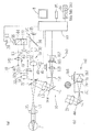
以下、本発明に係る実施形態を図面に基づいて説明する。図1は本実施形態に係る眼底カメラの光学系及び制御系の概略構成図である。光学系は、照明光学系10、被検者眼の眼底像を撮影する眼底観察・撮影光学系30、フォーカス指標投影光学系40、アライメント指標投影光学系50、前眼部観察光学系60、固視標呈示光学系70から大別構成されている。   Embodiments according to the present invention will be described below with reference to the drawings. FIG. 1 is a schematic configuration diagram of an optical system and a control system of a fundus camera according to the present embodiment. The optical system includes an illumination optical system 10, a fundus observation / imaging optical system 30 that captures a fundus image of a subject's eye, a focus index projection optical system 40, an alignment index projection optical system 50, an anterior segment observation optical system 60, a fixed eye. The optotype presenting optical system 70 is roughly divided.

<照明光学系> 照明光学系10は、観察照明光学系と撮影照明光学系を有する。撮影照明光学系は、フラッシュランプ等の撮影光源14、コンデンサレンズ15、円形遮光部を持つ第1遮光板17a(例えば、リングスリット)、円形遮光部を中心に有すると共にリング状の開口を有するリングスリット17b、円形遮光部を持つ第2遮光板17c(例えば、リングスリット)、リレーレンズ18、ミラー19、中心部に黒点を有する黒点板20、リレーレンズ21、孔あきミラー22、対物レンズ25を有する。   <Illumination Optical System> The illumination optical system 10 includes an observation illumination optical system and a photographing illumination optical system. The photographing illumination optical system includes a photographing light source 14 such as a flash lamp, a condenser lens 15, a first light shielding plate 17a (for example, a ring slit) having a circular light shielding part, a ring having a circular light shielding part and a ring-shaped opening. A slit 17b, a second light shielding plate 17c having a circular light shielding portion (for example, a ring slit), a relay lens 18, a mirror 19, a black spot plate 20 having a black spot at the center, a relay lens 21, a perforated mirror 22, and an objective lens 25 are provided. Have.

また、観察照明光学系は、ハロゲンランプ等の光源11、波長750nm以上の近赤外光を透過する赤外フィルタ12、コンデンサレンズ13、コンデンサレンズ13とリングスリット17bとの間に配置されたダイクロイックミラー16、第1遮光板17aから対物レンズ25までの光学系を有する。ダイクロイックミラー16は、赤外光源11からの光を反射し撮影光源14からの光を透過する特性を持つ。   The observation illumination optical system includes a light source 11 such as a halogen lamp, an infrared filter 12 that transmits near-infrared light having a wavelength of 750 nm or more, a condenser lens 13, and a dichroic disposed between the condenser lens 13 and the ring slit 17b. The optical system from the mirror 16 and the first light shielding plate 17a to the objective lens 25 is provided. The dichroic mirror 16 has a characteristic of reflecting light from the infrared light source 11 and transmitting light from the imaging light source 14.

上記光学系において、被検者眼と装置本体3の作動距離方向における位置関係が所定のアライメント基準位置(基準中心)に置かれたときに、被検者眼の瞳孔(虹彩)とリングスリット17bとが共役な位置となるように配置されている。また、リングスリット17bが瞳孔共役とされた状態で、第1遮光板17aは被検者眼の角膜、第2遮光板17cは被検者眼の水晶体後面、と共役になるように光学設計がされている。なお、照明光学系10に配置された第1遮光板17a、リングスリット17b、第2遮光板17cは、被検者眼前眼部の所定部位とそれぞれ共役になるように配置された遮光部材17を形成し、眼底撮影のための眼底照明光による角膜反射及び水晶体反射が眼底からの撮影光束に含まれて撮影用撮像素子35(後述する)に受光されるのを防止する有害反射光除去手段として機能する。   In the optical system, when the positional relationship between the subject's eye and the apparatus main body 3 in the working distance direction is placed at a predetermined alignment reference position (reference center), the pupil (iris) of the subject's eye and the ring slit 17b. Are arranged in a conjugate position. In addition, the optical design is such that the first light-shielding plate 17a is conjugated with the cornea of the subject's eye and the second light-shielding plate 17c is conjugated with the rear surface of the lens of the subject's eye with the ring slit 17b being conjugated with the pupil. Has been. The first light shielding plate 17a, the ring slit 17b, and the second light shielding plate 17c arranged in the illumination optical system 10 are provided with the light shielding member 17 arranged so as to be conjugated with a predetermined part of the anterior eye portion of the subject. As a harmful reflected light removing means for preventing the corneal reflection and the crystalline lens reflection caused by the fundus illumination light for photographing the fundus from being included in the photographing light flux from the fundus and being received by the photographing imaging device 35 (described later). Function.

<眼底観察・眼底撮影光学系> 眼底観察・撮影光学系30は、対物レンズ25、孔あきミラー22の開口近傍に位置する撮影絞り31、光軸方向に移動可能なフォーカシングレンズ32、結像レンズ33、眼底撮影時には挿脱機構39により光路から挿脱可能な跳ね上げミラー34を備え、撮影光学系と眼底観察光学系は対物レンズ25と撮影絞り31から結像レンズ33までの光学系を共用する。撮影絞り31は対物レンズ25に関して被検者眼Eの瞳孔と略共役な位置に配置されている。フォーカシングレンズ32は、モータを備える移動機構49により光軸方向に移動される。35は可視域に感度を有する撮影用二次元撮像素子である。跳ね上げミラー34の反射方向の光路には、P偏光を反射してS偏光を透過する偏光ビームスプリッタ37、リレーレンズ36、赤外域に感度を有する観察用二次元撮像素子38が配置されている。なお、レンズ32と撮影絞り31との間には、駆動部32cの駆動によって撮影光学系30の撮影光路に対して挿脱可能な視度補正レンズ32a、32b(マイナスレンズ32a,プラスレンズ32b)が設けられている。そして、レンズ32a、32bは、被検者眼が強度の屈折異常眼の場合に、手動又は自動的に光路中に各々挿入される。レンズ32a、32bが光路に挿入されると、これに対応する視度補正量が撮影光学系30に付与される。   <Fundus observation / fundus imaging optical system> The fundus observation / imaging optical system 30 includes an objective lens 25, a photographing diaphragm 31 located near the aperture of the perforated mirror 22, a focusing lens 32 movable in the optical axis direction, and an imaging lens. 33. At the time of fundus photography, a flip-up mirror 34 that can be inserted and removed from the optical path by the insertion / removal mechanism 39 is provided, and the photographing optical system and the fundus observation optical system share the objective lens 25 and the optical system from the photographing aperture 31 to the imaging lens 33. To do. The photographing aperture 31 is disposed at a position substantially conjugate with the pupil of the subject eye E with respect to the objective lens 25. The focusing lens 32 is moved in the optical axis direction by a moving mechanism 49 including a motor. Reference numeral 35 denotes a photographing two-dimensional image sensor having sensitivity in the visible range. A polarizing beam splitter 37 that reflects P-polarized light and transmits S-polarized light, a relay lens 36, and an observation two-dimensional imaging device 38 that has sensitivity in the infrared region are disposed in the optical path in the reflection direction of the flip-up mirror 34. . Diopter correction lenses 32a and 32b (a minus lens 32a and a plus lens 32b) that can be inserted into and removed from the photographing optical path of the photographing optical system 30 by driving the drive unit 32c between the lens 32 and the photographing diaphragm 31. Is provided. The lenses 32a and 32b are inserted into the optical path manually or automatically when the subject's eye is a strong refractive error eye. When the lenses 32 a and 32 b are inserted into the optical path, a corresponding diopter correction amount is given to the photographing optical system 30.

また、対物レンズ25と孔あきミラー22の間には、光路分岐部材としての挿脱可能なダイクロイックミラー(波長選択性ミラー)24が斜設されている。ダイクロイックミラー24は、アライメント指標投影光学系50及び前眼部照明光源58の波長光(中心波長940nm)を反射し、眼底観察用照明の波長光の光源波長(中心波長880nm)を含む波長900nm以下を透過する特性を有する。撮影時には、ダイクロイックミラー24は挿脱機構66により連動して跳ね上げられ、光路外に退避する。挿脱機構66は、ソレノイドとカム等により構成することができる。   A dichroic mirror (wavelength selective mirror) 24 that can be inserted and removed as an optical path branching member is provided obliquely between the objective lens 25 and the perforated mirror 22. The dichroic mirror 24 reflects the wavelength light (center wavelength 940 nm) of the alignment index projection optical system 50 and the anterior ocular segment illumination light source 58, and includes a light source wavelength (center wavelength 880 nm) of the wavelength light of the fundus observation illumination. It has a characteristic of transmitting through. At the time of shooting, the dichroic mirror 24 is flipped up by the insertion / removal mechanism 66 and retracts out of the optical path. The insertion / removal mechanism 66 can be composed of a solenoid and a cam.

観察用の光源11を発した光束は、赤外フィルタ12により赤外光束とされ、コンデンサレンズ13、ダイクロイックミラー16により反射されて第1遮光板17aを照明する。そして、第1遮光板17aを透過した光は、リングスリット17b、第2遮光板17c、リレーレンズ18、ミラー19、黒点板20、リレーレンズ21を経て孔あきミラー22に達する。孔あきミラー22で反射された光は、ダイクロイックミラー24を透過し、対物レンズ25により被検者眼Eの瞳孔付近で一旦収束した後、拡散して被検者眼眼底部を照明する。   The light beam emitted from the observation light source 11 is converted into an infrared light beam by the infrared filter 12 and reflected by the condenser lens 13 and the dichroic mirror 16 to illuminate the first light shielding plate 17a. The light transmitted through the first light shielding plate 17a reaches the perforated mirror 22 through the ring slit 17b, the second light shielding plate 17c, the relay lens 18, the mirror 19, the black spot plate 20, and the relay lens 21. The light reflected by the perforated mirror 22 is transmitted through the dichroic mirror 24, and once converged in the vicinity of the pupil of the eye E by the objective lens 25, then diffuses and illuminates the eye fundus of the subject.

また、眼底からの反射光は、対物レンズ25、ダイクロイックミラー24、孔あきミラー22の開口部、撮影絞り31、フォーカシングレンズ32、結像レンズ33、跳ね上げミラー34、偏光ビームスプリッタ37、リレーレンズ36を介して撮像素子38に結像する。なお、撮像素子38の出力は制御部80に入力され、モニタ8には、撮像素子38によって撮像される被検者眼の眼底観察像が表示される。   Reflected light from the fundus is obtained by the objective lens 25, the dichroic mirror 24, the aperture of the perforated mirror 22, the photographing aperture 31, the focusing lens 32, the imaging lens 33, the flip-up mirror 34, the polarization beam splitter 37, and the relay lens. An image is formed on the image sensor 38 via 36. The output of the image sensor 38 is input to the control unit 80, and the fundus observation image of the subject's eye captured by the image sensor 38 is displayed on the monitor 8.

また、撮影光源14から発した光束は、コンデンサレンズ15を介して、ダイクロイックミラー16を透過した後、眼底観察用の照明光と同様の光路を経て、眼底は可視光により照明される。そして、眼底からの反射光は対物レンズ25、孔あきミラー22の開口部、撮影絞り31、フォーカシングレンズ32、結像レンズ33を経て、二次元撮像素子35に結像する。   The luminous flux emitted from the imaging light source 14 passes through the dichroic mirror 16 via the condenser lens 15 and then passes through the same optical path as the illumination light for fundus observation, and the fundus is illuminated with visible light. Then, the reflected light from the fundus is imaged on the two-dimensional image sensor 35 through the objective lens 25, the aperture of the perforated mirror 22, the photographing aperture 31, the focusing lens 32, and the imaging lens 33.

<フォーカス指標投影光学系> フォーカス指標投影光学系(以下、投影光学系と省略する)40は、赤外光源41、スリット指標板42、この指標板42に取り付けられた2つの偏角プリズム43、偏光ビームスプリッタ44、を備える。また、投影光学系40は、ビームスプリッタ44〜レンズ25までの光路を照明光学系10と共用する。偏光ビームスプリッタ44は、照明光学系10の光路に配置され、照明光学系10の光路と投影光学系40の光路とを結合させる光結合部材として用いられる。   <Focus Index Projection Optical System> A focus index projection optical system (hereinafter abbreviated as a projection optical system) 40 includes an infrared light source 41, a slit index plate 42, and two declination prisms 43 attached to the index plate 42, A polarization beam splitter 44 is provided. Further, the projection optical system 40 shares the optical path from the beam splitter 44 to the lens 25 with the illumination optical system 10. The polarization beam splitter 44 is disposed in the optical path of the illumination optical system 10 and is used as an optical coupling member that couples the optical path of the illumination optical system 10 and the optical path of the projection optical system 40.

投影光学系40において、光の偏角方向が上下一対の関係となるように形成された2つの偏角プリズム43が投影光軸L3を挟んで左右に並べて配置されており、指標板42に形成され左右に延びるスリットと重ねられている。   In the projection optical system 40, two declination prisms 43 formed so that the declination directions of the light have a pair of upper and lower relationships are arranged side by side with the projection optical axis L3 interposed therebetween, and formed on the indicator plate 42. It is overlapped with a slit extending to the left and right.

また、投影光学系40は、指標光束を所定の偏光方向とするための第1の偏光部材を持ち、観察光学系30は、第1偏光部材で得られる所定の偏光方向を持つ指標光束を撮像素子38に対して制限する偏光部材を持つ。   The projection optical system 40 has a first polarizing member for setting the index light beam to a predetermined polarization direction, and the observation optical system 30 images the index light beam having a predetermined polarization direction obtained by the first polarizing member. A polarizing member that restricts the element 38 is provided.

より具体的には、指標投影光学系40及び観察光学系30には、それぞれ偏光方向が直交関係にある直線偏光板、又は、偏光方向が直交関係にある光の一方を透過もしくは反射により被検者眼に向かわせ他方を反射もしくは透過して撮像素子38に受光させる偏光ビームスプリッタ、が配置される。これにより、指標投影光束による対物レンズ25での反射光が撮像素子38に向かうのが制限される。   More specifically, each of the index projection optical system 40 and the observation optical system 30 is examined by transmitting or reflecting either a linearly polarizing plate having a polarization direction orthogonal to each other or light having a polarization direction orthogonal to each other. A polarizing beam splitter is disposed so as to face the human eye and reflect or transmit the other to be received by the image sensor 38. As a result, the reflected light from the objective lens 25 by the index projection light beam is restricted from traveling toward the image sensor 38.

例えば、偏光ビームスプリッタ44は、照明光学系10の照明光源(光源11、光源14)と孔あきミラー22との間に配置される(挿脱可能な構成を含む)。例えば、P偏光を透過してS偏光を反射する偏光ビームスプリッタが用いられる。また、投影光学系40の投影光軸L3は、眼底上でのフォーカス指標が黒点板20の影と重なるのを回避するべく、照明光学系10の光軸L2に対して垂直な方向にずれた位置に配置されるようにしてもよい。   For example, the polarization beam splitter 44 is disposed between the illumination light source (the light source 11 and the light source 14) of the illumination optical system 10 and the perforated mirror 22 (including a detachable configuration). For example, a polarization beam splitter that transmits P-polarized light and reflects S-polarized light is used. Further, the projection optical axis L3 of the projection optical system 40 is shifted in a direction perpendicular to the optical axis L2 of the illumination optical system 10 in order to avoid that the focus index on the fundus overlaps the shadow of the black spot plate 20. You may make it arrange | position to a position.

光源41から出射された投影光束は、指標板42のスリットを通過し、プリズム43によって各方向に偏角された後、ビームスプリッタ44にて反射される。ここで、光源41からの光束(自然光)は、ビームスプリッタ44によりS偏光が反射される。   The projected light beam emitted from the light source 41 passes through the slit of the indicator plate 42, is deflected in each direction by the prism 43, and then reflected by the beam splitter 44. Here, the S-polarized light of the light beam (natural light) from the light source 41 is reflected by the beam splitter 44.

そして、ビームスプリッタ44で反射された光束(S偏光)は、リレーレンズ21、孔あきミラー22、ダイクロイックミラー24、レンズ25を経て、眼底に投影される。そして、眼底に投影されたフォーカス用の光束は、眼底で乱反射されることによりP偏光とS偏光の反射光となる。この眼底反射光束は、レンズ25、孔あきミラー22の開口部〜跳ね上げミラーを介して、偏光ビームスプリッタ37に入射される。ここで、フォーカス指標による眼底反射光は、偏光ビームスプリッタ37によりP偏光が反射されS偏光が透過される。そして、偏光ビームスプリッタ37で反射された眼底反射光(P偏光)は、リレーレンズ36を介して撮像素子38に結像される。   The light beam (S-polarized light) reflected by the beam splitter 44 is projected onto the fundus through the relay lens 21, the perforated mirror 22, the dichroic mirror 24, and the lens 25. The focusing light beam projected on the fundus is irregularly reflected by the fundus and becomes P-polarized light and S-polarized light. The fundus reflection light flux is incident on the polarization beam splitter 37 via the lens 25 and the opening of the perforated mirror 22 to the flip-up mirror. Here, the fundus reflected light by the focus index is reflected by the polarization beam splitter 37 and is transmitted through the S-polarized light. The fundus reflection light (P-polarized light) reflected by the polarization beam splitter 37 forms an image on the image sensor 38 via the relay lens 36.

この場合、投影光学系40は、投影光源を有し被検者眼眼底にフォーカス用の指標を投影する指標投影光学系として用いられる。また、観察用二次元撮像素子38を有する観察光学系30は、投影光学系40による眼底反射光を受光する受光素子を有する受光光学系として用いられる。そして、投影光学系40と観察光学系30とによって、フォーカス検出光学系が形成される。   In this case, the projection optical system 40 is used as an index projection optical system that has a projection light source and projects a focus index onto the fundus of the subject's eye. The observation optical system 30 having the observation two-dimensional imaging element 38 is used as a light receiving optical system having a light receiving element that receives fundus reflected light from the projection optical system 40. The projection optical system 40 and the observation optical system 30 form a focus detection optical system.

図2は撮像素子38から出力される画像をモニタ8上に表示したものである。図示するように、スプリット指標(フォーカス指標)S1・S2が眼底上に投影されると、被検者眼の眼底に対する装置のフォーカス状態に応じて眼底上で所定方向に分離される。フォーカス指標像S1・S2は、撮像素子38によって眼底像と共に撮像される。   FIG. 2 shows an image output from the image sensor 38 on the monitor 8. As shown in the figure, when split indices (focus indices) S1 and S2 are projected onto the fundus, they are separated in a predetermined direction on the fundus according to the focus state of the apparatus with respect to the fundus of the subject's eye. The focus index images S1 and S2 are captured together with the fundus image by the image sensor 38.

撮像素子38から撮像信号がモニタ8に出力されると、検者は、スプリット指標の分離状態からフォーカスのずれを把握できる。また、制御部80は、スプリット指標の分離状態に基づいて眼底のフォーカス状態を電気的に検出し、その検出結果に基づいてレンズ32を自動的に移動させる(オートフォーカス制御)。   When the imaging signal is output from the imaging element 38 to the monitor 8, the examiner can grasp the focus shift from the split index separation state. Further, the control unit 80 electrically detects the fundus focus state based on the split index separation state, and automatically moves the lens 32 based on the detection result (auto focus control).

なお、フォーカス用の投影光束が対物レンズ25の各レンズ面、角膜、及び水晶体を通過する際に発生する反射光は、ほぼ鏡面反射であり、S偏光のまま偏光ビームスプリッタ37に到達し透過される。このため、フォーカス指標の投影によるフレア及びゴーストが撮像素子38に混入するのを回避できる。   The reflected light generated when the projection light beam for focusing passes through each lens surface, cornea, and crystalline lens of the objective lens 25 is almost specularly reflected and reaches the polarizing beam splitter 37 and is transmitted as it is with S-polarized light. The For this reason, it is possible to avoid flare and ghost due to the projection of the focus index from being mixed into the image sensor 38.

光源41を含む投影光学系40の一部(光源41、スリット指標板42、偏角プリズム43)は、レンズ32と連動して、光軸方向に移動される。例えば、レンズ32が正視眼に対応する位置に置かれると、正視眼の眼底と投影板42の開口とが略共役になるように投影光学系40の一部(光源41、スリット指標板42、プリズム43)が移動される。また、所定の球面度数(例えば、−3D)を持つ被検者眼に対してピントが合う位置にレンズ32が置かれると、その被検者眼の眼底と投影板42の開口とが略共役になるように投影光学系40の一部が移動される。   A part of the projection optical system 40 including the light source 41 (the light source 41, the slit indicator plate 42, and the deflection prism 43) is moved in the optical axis direction in conjunction with the lens 32. For example, when the lens 32 is placed at a position corresponding to the normal eye, a part of the projection optical system 40 (light source 41, slit index plate 42, so that the fundus of the normal eye and the opening of the projection plate 42 are substantially conjugate with each other). The prism 43) is moved. When the lens 32 is placed at a position where the subject's eye having a predetermined spherical power (for example, −3D) is in focus, the fundus of the subject's eye and the opening of the projection plate 42 are substantially conjugate. A part of the projection optical system 40 is moved so that

移動機構46は、モータを持ち、光源41を含む投影光学系40の一部をビームスプリッタ44に対して光軸方向に移動させる。投影光学系40の移動範囲は、レンズ32の移動のみによる視度補正量に対応する移動範囲に加えて、レンズ32a、32bの挿入による視度補正量に対応する移動範囲が確保されている。すなわち、移動機構46は、視度補正レンズが挿入された状態でのフォーカシングレンズ32の移動による視度補正範囲を含む移動可能範囲を持つ。   The moving mechanism 46 has a motor and moves a part of the projection optical system 40 including the light source 41 in the optical axis direction with respect to the beam splitter 44. As for the movement range of the projection optical system 40, in addition to the movement range corresponding to the diopter correction amount due to only the movement of the lens 32, the movement range corresponding to the diopter correction amount due to the insertion of the lenses 32a and 32b is secured. That is, the moving mechanism 46 has a movable range including a diopter correction range due to the movement of the focusing lens 32 in a state where the diopter correction lens is inserted.

この場合、投影光学系40の移動範囲は、撮影光路に対するレンズ32a、32bの挿脱状態に応じて移動範囲が切換えられる。挿脱状態に応じて移動範囲が設定されると、投影光学系40は、その移動範囲において、レンズ32と連動して移動される(詳しくは、後述する)。   In this case, the movement range of the projection optical system 40 is switched according to the insertion / removal state of the lenses 32a and 32b with respect to the photographing optical path. When the movement range is set according to the insertion / removal state, the projection optical system 40 is moved in conjunction with the lens 32 within the movement range (details will be described later).

図1の説明に戻る。<アライメント指標投影光学系> アライメント用指標光束を投影するアライメント指標投影光学系50には、図1の左上の点線A内の図に示すように、撮影光軸L1を中心として同心円上に45度間隔で赤外光源が複数個配置されており、撮影光軸L1を通る垂直平面を挟んで左右対称に配置された赤外光源51とコリメーティングレンズ52を持つ第1指標投影光学系(0度、及び180)と、第1指標投影光学系とは異なる位置に配置され6つの赤外光源53を持つ第2指標投影光学系と、を備える。この場合、第1指標投影光学系は被検者眼Eの角膜に無限遠の指標を左右方向から投影し、第2指標投影光学系は被検者眼Eの角膜に有限遠の指標を上下方向もしくは斜め方向から投影する構成となっている。なお、図1の本図には、便宜上、第1指標投影光学系(0度、及び180度)と、第2指標投影光学系の一部のみ(45度、135度)が図示されている。   Returning to the description of FIG. <Alignment Index Projection Optical System> The alignment index projection optical system 50 that projects the alignment index beam is 45 degrees concentrically about the photographing optical axis L1 as shown in the diagram in the dotted line A in the upper left of FIG. A plurality of infrared light sources are arranged at intervals, and a first index projection optical system (0) having an infrared light source 51 and a collimating lens 52 arranged symmetrically with respect to a vertical plane passing through the photographing optical axis L1. And a second index projection optical system having six infrared light sources 53 arranged at positions different from the first index projection optical system. In this case, the first index projection optical system projects an infinite distance index on the cornea of the subject's eye E from the left and right directions, and the second index projection optical system moves the finite distance index on the cornea of the subject's eye E up and down. Projection is performed from a direction or an oblique direction. In FIG. 1, for convenience, the first index projection optical system (0 degrees and 180 degrees) and only a part of the second index projection optical system (45 degrees and 135 degrees) are shown. .

<前眼部観察光学系> 被検者眼の前眼部を撮像する前眼部観察(撮影)光学系60は、ダイクロイックミラー24の反射側に、フィールドレンズ61、ミラー62、絞り63、リレーレンズ64、赤外域の感度を持つ二次元撮像素子(受光素子)65を備える。また、二次元撮像素子65はアライメント指標検出用の撮像手段を兼ね、中心波長940nmの赤外光を発する前眼部照明光源58により照明された前眼部とアライメント指標が撮像される。前眼部照明光源58により照明された前眼部は、対物レンズ25、ダイクロイックミラー24及びフィールドレンズ61からリレーレンズ64の光学系を介して二次元撮像素子65により受光される。また、アライメント指標投影光学系50が持つ光源から発せられたアライメント光束は被検者眼角膜に投影され、その角膜反射像は対物レンズ25〜リレーレンズ64を介して二次元撮像素子65に受光(投影)される。二次元撮像素子65の出力は制御部80に入力され、モニタ8には二次元撮像素子65によって撮像された前眼部像が表示される。なお、前眼部観察光学系60は、被検者眼に対する装置本体のアライメント状態を検出する役割を兼用する。   <Anterior Eye Observation Optical System> An anterior eye observation (imaging) optical system 60 that images the anterior eye part of a subject's eye is provided with a field lens 61, a mirror 62, a diaphragm 63, and a relay on the reflection side of the dichroic mirror 24. A lens 64 and a two-dimensional imaging element (light receiving element) 65 having infrared sensitivity are provided. The two-dimensional imaging element 65 also serves as an imaging means for detecting an alignment index, and the anterior segment illuminated by the anterior segment illumination light source 58 that emits infrared light having a center wavelength of 940 nm and the alignment index are imaged. The anterior segment illuminated by the anterior segment illumination light source 58 is received by the two-dimensional imaging element 65 from the objective lens 25, the dichroic mirror 24, and the field lens 61 via the relay lens 64 optical system. In addition, the alignment light beam emitted from the light source of the alignment index projection optical system 50 is projected onto the subject's eye cornea, and the cornea reflection image is received by the two-dimensional image sensor 65 via the objective lens 25 to the relay lens 64 ( Projected). The output of the two-dimensional image sensor 65 is input to the control unit 80, and the anterior segment image captured by the two-dimensional image sensor 65 is displayed on the monitor 8. The anterior ocular segment observation optical system 60 also serves to detect the alignment state of the apparatus main body with respect to the subject's eye.

<固視標呈示光学系> 被検者眼を固視させるための固視標を呈示する固視標呈示光学系70は、赤色の光源74、開口穴が形成された遮光板71、リレーレンズ75を備え、偏光ビームスプリッタ37を介して跳ね上げミラー34から対物レンズ25までの観察光学系30の光路を共用する。   <Fixed Target Presenting Optical System> A fixed target presenting optical system 70 for presenting a fixed target for fixing a subject's eye includes a red light source 74, a light shielding plate 71 in which an aperture is formed, and a relay lens. 75, and shares the optical path of the observation optical system 30 from the flip-up mirror 34 to the objective lens 25 via the polarization beam splitter 37.

この場合、光源74により遮光板71が背後から照明されることにより固視標(固視灯)となる。そして、固視標からの光束は、リレーレンズ75、偏光ビームスプリッタ37、跳ね上げミラー34、結像レンズ33、フォーカシングレンズ32、孔あきミラー22、ダイクロイックミラー24、対物レンズ25を通過して被検者眼眼底に集光し、被検者は開口穴71からの光束を固視標として視認する。   In this case, the light shielding plate 71 is illuminated from behind by the light source 74 to become a fixation target (fixation lamp). Then, the light beam from the fixation target passes through the relay lens 75, the polarization beam splitter 37, the flip-up mirror 34, the imaging lens 33, the focusing lens 32, the perforated mirror 22, the dichroic mirror 24, and the objective lens 25. The light is condensed on the eye fundus of the examiner, and the subject visually recognizes the light flux from the opening hole 71 as a fixation target.

<制御系> 二次元撮像素子65、38、35は制御部80に接続されている。制御部80は二次元撮像素子65に撮像された前眼部画像からアライメント指標を検出処理する。また、制御部80は、二次元撮像素子38に撮像された眼底画像からフォーカス指標を検出処理する。また、制御部80はモニタ8に接続され、その表示画像を制御する。制御部80には、他に、移動機構49、移動機構46、挿脱機構39、各種のスイッチを持つスイッチ部84、記憶手段としてのメモリ85、各光源等が接続されている。なお、スイッチ部84には、フォーカス調整を行うためのフォーカス調整スイッチ84a、撮影開始スイッチ84b、レンズ32a、32bを挿脱させるための切換スイッチ84c、等が配置されている。   <Control System> The two-dimensional imaging elements 65, 38, and 35 are connected to the control unit 80. The control unit 80 detects an alignment index from the anterior segment image captured by the two-dimensional image sensor 65. In addition, the control unit 80 detects a focus index from the fundus image captured by the two-dimensional image sensor 38. The control unit 80 is connected to the monitor 8 and controls the display image. In addition, the control unit 80 is connected to a moving mechanism 49, a moving mechanism 46, an insertion / removal mechanism 39, a switch unit 84 having various switches, a memory 85 as a storage unit, and light sources. The switch unit 84 is provided with a focus adjustment switch 84a for performing focus adjustment, a shooting start switch 84b, a changeover switch 84c for inserting and removing the lenses 32a and 32b, and the like.

上記のような構成を持つ装置の動作を説明する。まず、検者は、被検者の顔を図示無き顔支持ユニットにより支持する。ここで、検者は、図示無きジョイスティックの操作により前述の光学系が内蔵された装置本体を左右上下に移動させて、被検者眼に対するアライメントを行う。この場合、前眼部観察光学系60によって撮像される前眼部画像をモニタ8に出力することで、アライメントをスムーズに行える。   The operation of the apparatus having the above configuration will be described. First, the examiner supports the subject's face with a face support unit (not shown). Here, the examiner moves the apparatus main body in which the above-described optical system is built up to the left and right and up and down by operating a joystick (not shown) to perform alignment with the eye of the subject. In this case, alignment can be performed smoothly by outputting the anterior segment image captured by the anterior segment observation optical system 60 to the monitor 8.

ラフなアライメントが完了されると、撮像素子38による眼底像がモニタ8に表示される。検者はこの眼底画像を見ながら、所望する状態で撮影できるように、さらに図示無きジョイスティックの手動操作にてアライメント状態を微調整する。   When rough alignment is completed, a fundus image by the image sensor 38 is displayed on the monitor 8. The examiner finely adjusts the alignment state by manual operation of a joystick (not shown) so that the fundus image can be taken in a desired state while viewing the fundus image.

眼底像の観察によりアライメントの微調整を行った後は、図2に示されるように、中心にフォーカス視標投影光学系40によるフォーカス指標像S1、S2が投影されているので、この指標像に基づいてレンズ32を光軸方向に移動させ、眼底のフォーカス合わせを行う。   After finely adjusting the alignment by observing the fundus image, focus index images S1 and S2 by the focus target projection optical system 40 are projected at the center as shown in FIG. Based on this, the lens 32 is moved in the optical axis direction to focus the fundus.

なお、初期状態においては、撮影光路に視度補正レンズが挿入されていないので、制御部80は、レンズ32の移動のみによる視度補正範囲に対応する移動範囲内において、レンズ32の移動に連動するように指標投影光学系40を光軸方向に移動させる(図3(a)参照)。   In the initial state, since the diopter correction lens is not inserted in the photographing optical path, the control unit 80 is linked to the movement of the lens 32 within the movement range corresponding to the diopter correction range based on the movement of the lens 32 only. Thus, the index projection optical system 40 is moved in the optical axis direction (see FIG. 3A).

なお、フォーカス合わせは、フォーカス調整スイッチ84aを用いた検者のマニュアルフォーカス、又は制御部80によるオートフォーカス、によって行われる。なお、オートフォーカスの場合、制御部80は、フォーカス指標像S1,S2が一致するように移動機構49を駆動制御する。なお、フォーカス合わせが完了した後、自動もしくも手動にて出力されるトリガ信号にもとづいて撮影が実行される。   Note that focusing is performed by manual focus of the examiner using the focus adjustment switch 84a or auto focus by the control unit 80. In the case of autofocus, the control unit 80 controls driving of the moving mechanism 49 so that the focus index images S1 and S2 coincide. Note that after the focusing is completed, photographing is performed based on a trigger signal output automatically or manually.

ここで、撮影開始のトリガ信号が発せられると、制御部80は、挿脱機構39を駆動させることにより跳ね上げミラー34を光路から離脱させ、挿脱機構66を駆動することによりダイクロイックミラー24を光路から離脱させると共に、撮影光源14を発光する。このとき、二次元撮像素子35によって眼底像が撮影され、メモリ85に撮影された画像データが記憶される。そして、制御部80は、モニタ8の表示画面を二次元撮像素子35で撮影されたカラーの眼底画像に切換える。   Here, when a trigger signal for starting imaging is generated, the control unit 80 drives the insertion / removal mechanism 39 to disengage the flip-up mirror 34 from the optical path, and drives the insertion / removal mechanism 66 to move the dichroic mirror 24. While being separated from the optical path, the photographing light source 14 emits light. At this time, a fundus image is captured by the two-dimensional image sensor 35 and the captured image data is stored in the memory 85. Then, the control unit 80 switches the display screen of the monitor 8 to a color fundus image captured by the two-dimensional image sensor 35.

なお、上記構成において、被検者眼が強度近視眼又は強度遠視眼でフォーカスが合わせられない場合、検者は、切換スイッチ84cを押して、レンズ32a、32bを撮影光路に挿入してフォーカスを合わせる。この場合、レンズ32a、32bが自動的に挿入されるようにしてもよい。例えば、レンズ32が移動限界位置に達しても、フォーカスが一致しなかった場合、視度補正レンズが自動的に挿入される。   In the above configuration, when the subject's eye is an intense myopic eye or an intense hyperopic eye and the focus cannot be adjusted, the examiner pushes the changeover switch 84c and inserts the lenses 32a and 32b into the imaging optical path to adjust the focus. In this case, the lenses 32a and 32b may be automatically inserted. For example, if the focus does not match even when the lens 32 reaches the movement limit position, a diopter correction lens is automatically inserted.

ここで、制御部80は、挿入された視度補正レンズとレンズ32の移動位置とによる視度補正量に対応する移動位置に、投影光学系40の一部を移動機構49を用いて移動させる。   Here, the control unit 80 uses the moving mechanism 49 to move a part of the projection optical system 40 to a movement position corresponding to the diopter correction amount based on the inserted diopter correction lens and the movement position of the lens 32. .

より具体的には、視度補正レンズの挿脱状態に応じて,投影光源41を含む指標投影光学系40の一部の移動位置を補正する。なお、制御部80は、レンズ32a,レンズ32bの近傍に設置可能なセンサ(例えば、フォトセンサ)、切換スイッチ84cから出力される切換信号、駆動部からの駆動信号等から、撮影光路に対する視度補正レンズの個々の挿入状態を判別できる。   More specifically, the movement position of a part of the index projection optical system 40 including the projection light source 41 is corrected according to the insertion / removal state of the diopter correction lens. Note that the control unit 80 uses a sensor (for example, a photosensor) that can be installed in the vicinity of the lens 32a and the lens 32b, a switching signal output from the selector switch 84c, a driving signal from the driving unit, and the like, and a diopter for the photographing optical path Individual insertion states of the correction lens can be determined.

図3は、各レンズ32a,32bの退避時、レンズ32a挿入時、レンズ32b挿入時、に応じて設定される指標投影光学系40の移動範囲を示す具体例である。レンズ32a、32bの退避時においては、図3(a)に示すように、レンズ32a、32bが退避された状態でのレンズ32の移動による所定の視度補正範囲(−12D〜0D〜+12D)に対応する移動範囲が設定される。   FIG. 3 is a specific example showing the movement range of the index projection optical system 40 set according to when the lenses 32a and 32b are retracted, when the lens 32a is inserted, and when the lens 32b is inserted. When the lenses 32a and 32b are retracted, as shown in FIG. 3A, a predetermined diopter correction range (−12D to 0D to + 12D) due to the movement of the lens 32 when the lenses 32a and 32b are retracted. The movement range corresponding to is set.

図3(b)に示すように、レンズ32aの挿入時においては、レンズ32a(例えば、視度補正量が−18Dのレンズ)が挿入された状態でのレンズ32の移動による所定の視度補正範囲(例えば、−30D〜−18D〜−6D)に対応する移動範囲が設定される。   As shown in FIG. 3B, when the lens 32a is inserted, a predetermined diopter correction is performed by moving the lens 32 in a state where the lens 32a (for example, a lens having a diopter correction amount of −18D) is inserted. A moving range corresponding to the range (for example, −30D to −18D to −6D) is set.

より具体的には、レンズ32aが挿入されたとき、制御部80は、レンズ32aが持つ視度補正量(例えば、−18D)に対応する投影光学系40の移動方向(−方向)及び移動距離を設定する。例えば、制御部80は、レンズ挿入前の投影光学系40の移動位置(例えば、−12D)に対して視度補正レンズ32aの視度補正量(−18D)を加えた移動位置(−30D)に、投影光学系40を移動させる。   More specifically, when the lens 32a is inserted, the control unit 80 moves the movement direction (− direction) and the movement distance of the projection optical system 40 corresponding to the diopter correction amount (for example, −18D) of the lens 32a. Set. For example, the control unit 80 adds the diopter correction amount (−18D) of the diopter correction lens 32a to the move position (−12D) of the projection optical system 40 before the lens is inserted (−30D). Then, the projection optical system 40 is moved.

この場合、制御部80は、移動機構49の駆動を制御し、レンズ32a挿入前の視度補正量に対応する移動位置にレンズ32を移動させるようにしてもよい。これにより、レンズ挿入状態に移行後、レンズ32a挿入前の視度補正量からのフォーカス調整が可能となる。   In this case, the control unit 80 may control the driving of the moving mechanism 49 to move the lens 32 to a moving position corresponding to the diopter correction amount before insertion of the lens 32a. Thereby, after shifting to the lens insertion state, focus adjustment from the diopter correction amount before insertion of the lens 32a becomes possible.

図3(c)に示すように、レンズ32bの挿入時においては、レンズ32b(例えば、視度補正量が+18Dのレンズ)が挿入された状態でのレンズ32の移動による所定の視度補正範囲(例えば、+6D〜+18D〜+30D)に対応する移動範囲が設定される。なお、具体的な動作については、レンズ32aと同様の手法を用いることができるため、詳しい説明を省略する。   As shown in FIG. 3C, when the lens 32b is inserted, a predetermined diopter correction range due to the movement of the lens 32 with the lens 32b (for example, a lens with a diopter correction amount of + 18D) inserted. A moving range corresponding to (for example, + 6D to + 18D to + 30D) is set. In addition, about a specific operation | movement, since the method similar to the lens 32a can be used, detailed description is abbreviate | omitted.

上記のように投影光学系40の移動が完了されると、強度屈折異常眼に対するフォーカス合わせができるようになる。そこで、制御部80は、フォーカス指標像S1,S2の分離情報を基に、両者が一致するように移動機構49を駆動制御して眼底のフォーカス合わせを行う。また、指標像S1,S2が一致されるように、検者によるマニュアルフォーカスも可能である。   When the movement of the projection optical system 40 is completed as described above, it is possible to perform focusing with respect to an eye with abnormal refractive power. Therefore, based on the separation information of the focus index images S1 and S2, the control unit 80 performs driving control of the moving mechanism 49 so that the two coincide with each other, thereby focusing the fundus. Further, manual focusing by the examiner is also possible so that the index images S1 and S2 are matched.

この場合、制御部80は、挿入された視度補正レンズとレンズ32の移動とによる視度補正範囲に対応する移動範囲内において、レンズ32の移動と連動するように指標投影光学系40を光軸方向に移動させる。例えば、レンズ32aが挿入された場合、制御部80は、レンズ32aに対応する移動範囲内において、投影光学系40を移動させる。そして、レンズ32が移動されたら、制御部80は、レンズ32の移動による視度補正分、投影光学系40を移動させる。   In this case, the control unit 80 illuminates the index projection optical system 40 so as to be interlocked with the movement of the lens 32 within the movement range corresponding to the diopter correction range by the inserted diopter correction lens and the movement of the lens 32. Move in the axial direction. For example, when the lens 32a is inserted, the control unit 80 moves the projection optical system 40 within a movement range corresponding to the lens 32a. When the lens 32 is moved, the control unit 80 moves the projection optical system 40 by the amount of diopter correction due to the movement of the lens 32.

上記のような構成とすれば、被検者眼が強度の屈折異常眼であって、視度補正用レンズが撮影光学系30の撮影光路に挿入された状態であっても、眼底上のフォーカス指標がフォーカス検出可能な状態で撮像素子38上に受光される。このため、適正なオートフォーカス制御が可能となる。また、検者は、視度補正レンズが挿入されていない状態と同様の動作にて、マニュアルフォーカスを行うことができる。   With the configuration as described above, even if the subject's eye is an intense refractive error eye and the diopter correcting lens is inserted in the photographing optical path of the photographing optical system 30, the focus on the fundus The index is received on the image sensor 38 in a state where focus detection is possible. For this reason, appropriate autofocus control is possible. Further, the examiner can perform manual focus by the same operation as in the state where the diopter correction lens is not inserted.

なお、上記構成において、視度補正レンズの挿入に対応する補正レンズを投影光学系40の光路中に挿脱可能な構成としてもよい。例えば、レンズ32aが挿入された場合、ビームスプリッタ44とプリズム43との間に、レンズ32aが持つ視度補正量に対応するマイナスレンズが挿入される。このようにすれば、投影光学系40の移動量が少なくて済む。この場合、レンズ32aが挿入された状態での投影光学系40の移動可能範囲と、レンズ32aが外された状態での投影光学系40の移動可能範囲と、を略同一とすることも可能である。   In the above-described configuration, a correction lens corresponding to the insertion of the diopter correction lens may be inserted into and removed from the optical path of the projection optical system 40. For example, when the lens 32 a is inserted, a minus lens corresponding to the diopter correction amount of the lens 32 a is inserted between the beam splitter 44 and the prism 43. In this way, the movement amount of the projection optical system 40 can be reduced. In this case, the movable range of the projection optical system 40 with the lens 32a inserted may be substantially the same as the movable range of the projection optical system 40 with the lens 32a removed. is there.

次に、第2の実施形態に係る構成について説明する。なお、図4において、図1と同様の番号を付したものついては、特段の説明がない限り、同様の構成・機能を有するものとする。図4においては、被検者眼眼底とのフォーカス状態を検出する構成として、被検者眼の瞳孔中心部を介して被検者眼眼底にスポット状の光束を投影する指標投影光学系140と、被検者眼眼底からの反射光を被検者眼前眼部から所定のパターン像(例えば、リングパターン像、または、複数のスポット像)として取り出して二次元受光素子に受光させる受光光学系160と、が設けられている。   Next, a configuration according to the second embodiment will be described. In FIG. 4, the same reference numerals as those in FIG. 1 have the same configuration / function unless otherwise specified. In FIG. 4, as a configuration for detecting the focus state with the subject's eye fundus, an index projection optical system 140 that projects a spot-like light beam onto the subject's eye fundus through the center of the pupil of the subject's eye; The light receiving optical system 160 takes out the reflected light from the eye fundus of the subject as a predetermined pattern image (for example, a ring pattern image or a plurality of spot images) from the anterior eye portion of the subject and causes the two-dimensional light receiving element to receive the light. And are provided.

図4(a)において、投影光学系140は、投影光軸L3上に配置されたLEDやSLD等の赤外点光源141、投影レンズ142、フォーカス光束と眼底観察光束を分岐する光路分割部材としてのビームスプリッタ144を含み、さらに、ビームスプリッタ144〜レンズ32〜対物レンズ25までの光路を眼底観察光学系30と共用する。なお、ダイクロイックミラー137は、可視光を反射し赤外光を透過する特性を有する。   In FIG. 4A, the projection optical system 140 is an infrared point light source 141 such as an LED or SLD arranged on the projection optical axis L3, a projection lens 142, and an optical path dividing member that branches the focus light beam and the fundus observation light beam. In addition, the optical path from the beam splitter 144 to the lens 32 to the objective lens 25 is shared with the fundus oculi observation optical system 30. The dichroic mirror 137 has a characteristic of reflecting visible light and transmitting infrared light.

一方、受光光学系160は、対物レンズ25〜ビームスプリッタ169までの光路を照明光学系10と共用し、さらに、ビームスプリッタ169の反射方向に、略眼底共役位置に配置されるピンホール開口161、コリメータレンズ163、リングレンズ165、及び略眼底共役位置に配置される二次元受光素子167を含む。なお、受光素子167を含む受光光学系160の一部(例えば、ピンホール開口161〜二次元受光素子167)は、移動機構46の駆動によって、レンズ32の移動に連動して光軸方向に移動可能な構成となっている。例えば、レンズ32が正視眼に対応する位置に置かれると、正視眼の眼底と開口161とが略共役になるように受光光学系160の一部が移動される。また、所定の球面度数(例えば、−3D)を持つ被検者眼に対してピントが合う位置にレンズ32が置かれると、その被検者眼の眼底と開口161とが略共役になるように投影光学系40の一部が移動される。レンズ32の移動に連動して移動される受光光学系160の一部は、図1に示した第1実施形態における投影光学系40の一部と同様に、レンズ32a、32bの挿入に応じて移動位置が補正される。受光光学系160の移動と共に、光源140を含む投影光学系140の一部が移動されるような構成であってもよい。   On the other hand, the light receiving optical system 160 shares the optical path from the objective lens 25 to the beam splitter 169 with the illumination optical system 10, and further, a pinhole opening 161 disposed at a substantially fundus conjugate position in the reflection direction of the beam splitter 169, It includes a collimator lens 163, a ring lens 165, and a two-dimensional light receiving element 167 disposed substantially at the fundus conjugate position. A part of the light receiving optical system 160 including the light receiving element 167 (for example, the pinhole opening 161 to the two-dimensional light receiving element 167) moves in the optical axis direction in conjunction with the movement of the lens 32 by driving the moving mechanism 46. It has a possible configuration. For example, when the lens 32 is placed at a position corresponding to the normal eye, a part of the light receiving optical system 160 is moved so that the fundus of the normal eye and the opening 161 are substantially conjugate. Further, when the lens 32 is placed at a position where the subject's eye having a predetermined spherical power (for example, −3D) is in focus, the fundus of the subject's eye and the opening 161 are substantially conjugate. The projection optical system 40 is partially moved. A part of the light receiving optical system 160 moved in conjunction with the movement of the lens 32 corresponds to the insertion of the lenses 32a and 32b, like the part of the projection optical system 40 in the first embodiment shown in FIG. The movement position is corrected. A configuration in which a part of the projection optical system 140 including the light source 140 is moved along with the movement of the light receiving optical system 160 may be adopted.

ここで、リングレンズ165は、レンズ部と、リング開口を持つリング指標板と、から構成され、瞳孔と略共役な位置に配置される。また、二次元受光素子167は、レンズ部の焦点位置に配置され、眼底と撮像素子38(撮像素子35)とのフォーカスがあっているときに眼底と共役となる。ここで、リング指標板は、レンズ32と二次元受光素子167との間の被検者眼前眼部と略共役な位置(例えば、被検者眼瞳孔と略共役な位置、又は被検者眼角膜と略共役な位置)に配置される。   Here, the ring lens 165 includes a lens portion and a ring indicator plate having a ring opening, and is disposed at a position substantially conjugate with the pupil. The two-dimensional light receiving element 167 is disposed at the focal position of the lens unit, and is conjugate with the fundus when the fundus is in focus with the image sensor 38 (image sensor 35). Here, the ring indicator plate is positioned substantially conjugate with the anterior eye portion of the subject between the lens 32 and the two-dimensional light receiving element 167 (for example, a location substantially conjugate with the subject's eye pupil or the subject's eye). (Position substantially conjugate with the cornea).

また、光源141から出射された光は、レンズ142〜跳ね上げミラー34〜対物レンズ25を経て、被検者眼眼底上に投影され、眼底上にスポット状の点光源像が投影される。また、眼底に投影された点光源像は反射・散乱されて被検者眼を射出し、対物レンズ25〜ホールミラーの反射面を経て、ビームスプリッタ169、ピンホール開口161、コリメータレンズ163を介して、リングレンズ165によって収束された後、二次元受光素子167上にリング像として結像される。   The light emitted from the light source 141 passes through the lens 142, the flip-up mirror 34, and the objective lens 25, and is projected onto the eye fundus of the subject's eye, and a spot-like point light source image is projected onto the fundus. The point light source image projected onto the fundus is reflected and scattered and exits the subject's eye, passes through the reflecting surface of the objective lens 25 to the hole mirror, and passes through the beam splitter 169, the pinhole aperture 161, and the collimator lens 163. Then, after being converged by the ring lens 165, it is formed as a ring image on the two-dimensional light receiving element 167.

ここで、二次元受光素子167からの受光信号は、制御部80に入力される。ここで、被検者眼眼底のフォーカスがあっているときには、二次元受光素子167上にはリングレンズ165と同じサイズのぼけの少ない細いリング像が結像される。一方、被検者眼眼底のフォーカスが合っていないとき、二次元受光素子167上には、ぼけた太いリング像であって、フォーカスがあっている状態のリング像の大きさと異なるリング像が受光される。この場合、被検者眼の球面屈折誤差がある場合、リング像は、被検者眼の球面屈折誤差の大きさに比例した大きさとなる。また、乱視屈折誤差がある場合は、二次元受光素子167にできるリング像は、乱視屈折誤差に応じて楕円形状となる。   Here, the light reception signal from the two-dimensional light receiving element 167 is input to the control unit 80. Here, when the fundus of the subject's fundus is in focus, a thin ring image with the same size as the ring lens 165 and with little blur is formed on the two-dimensional light receiving element 167. On the other hand, when the fundus of the subject's fundus is out of focus, a ring image that is a blurred thick ring image that is different from the size of the focused ring image is received on the two-dimensional light receiving element 167. Is done. In this case, when there is a spherical refraction error of the subject's eye, the ring image has a size proportional to the magnitude of the spherical refraction error of the subject's eye. If there is an astigmatism refraction error, the ring image formed on the two-dimensional light receiving element 167 has an elliptical shape according to the astigmatism refraction error.

したがって、制御部80は、二次元受光素子167上にできるリング像を解析することにより、被検者眼のフォーカス状態を検出できる。そして、制御部80は、検出されるフォーカス状態に基づいて移動機構46及び移動機構49を駆動制御して眼底のフォーカス合わせを行う。この場合、制御部80は、移動機構49を用いてレンズ32を光軸方向に移動させると共に、移動機構46を用いて受光光学系160の一部を移動させる。例えば、二次元受光素子167上のリング像が最も細くなる或いは最も明るくなるようにして、二次元受光素子167を被検者眼の眼底と共役な位置にあわせる。これにより、眼底撮影用の撮像素子35(又は眼底観察用の撮像素子38)と被検者眼眼底とのフォーカス調整がなされる。   Therefore, the control unit 80 can detect the focus state of the subject's eye by analyzing the ring image formed on the two-dimensional light receiving element 167. Then, the control unit 80 performs driving control of the moving mechanism 46 and the moving mechanism 49 based on the detected focus state, thereby performing focus adjustment on the fundus. In this case, the control unit 80 moves the lens 32 in the optical axis direction using the moving mechanism 49 and moves a part of the light receiving optical system 160 using the moving mechanism 46. For example, the ring image on the two-dimensional light receiving element 167 is made the thinnest or brightest so that the two-dimensional light receiving element 167 is aligned with the fundus of the subject's eye. As a result, focus adjustment between the fundus imaging image sensor 35 (or the fundus observation image sensor 38) and the eye fundus of the subject is performed.

また、上記第2実施形態において、ビームスプリッタ144、ビームスプリッタ169に代えて第1実施形態にて示したような、偏光方向が互いに直交する光のうち、一方の光を反射して他方の光を透過する特性を有する偏光ビームスプリッタを用いるようにしてもよい。   Further, in the second embodiment, instead of the beam splitter 144 and the beam splitter 169, one of the lights whose polarization directions are orthogonal to each other as shown in the first embodiment is reflected and the other light is reflected. A polarizing beam splitter having a characteristic of transmitting the light may be used.

また、上記構成において、乱視検出やリング像の取得をしない場合、図4(b)に示すように、パターン指標板として受光光軸から等距離離れた位置に2つの開孔が形成された2穴絞り170と、集光部材として2穴絞り170を通過した光を二次元受光素子167上で集光させる結像レンズ171と、を用いるようにしてもよい。なお、図4(b)の場合、フォーカスが合っているときに、2つのスポット像が重なって二次元受光素子167上における受光光軸上で1つのスポット像となり、フォーカスがずれているときに、二次元受光素子167上で2つのスポット像となる。   Further, in the above configuration, when astigmatism detection or ring image acquisition is not performed, as shown in FIG. 4B, two apertures are formed at positions that are equidistant from the light receiving optical axis as a pattern index plate. You may make it use the aperture stop 170 and the imaging lens 171 which condenses the light which passed the 2 aperture stop 170 as a condensing member on the two-dimensional light receiving element 167. FIG. In the case of FIG. 4B, when the focus is achieved, the two spot images overlap to form one spot image on the light receiving optical axis on the two-dimensional light receiving element 167, and the focus is shifted. Two spot images are formed on the two-dimensional light receiving element 167.

なお、フォーカス検出光学系として、リング指標像を二次元受光素子に受光させる構成(図4(a)参照)を設けることにより、画像のぼけが何に起因するものかを判断可能となる。被検者眼が乱視眼の場合における二次元受光素子167上のリング像は、長径と短径を持つ楕円形状となる。そして、リング像の長径及び短径は、被検者眼の乱視度数に応じて変化する。   As the focus detection optical system, by providing a configuration (see FIG. 4A) in which the ring index image is received by the two-dimensional light receiving element, it is possible to determine what causes the image blur. When the subject's eye is an astigmatic eye, the ring image on the two-dimensional light receiving element 167 has an elliptical shape having a major axis and a minor axis. The major axis and minor axis of the ring image change according to the astigmatism power of the subject's eye.

ここで、制御部80は、二次元受光素子167によって取得されるリング画像に基づいてフォーカス状態を検出する。そして、制御部80は、検出されたフォーカス状態に基づいて被検者眼の等価球面度数に対応する位置にレンズ32が配置されるように移動機構49を駆動制御する。また、制御部80は、レンズ32の移動に連動して受光光学系160の一部を移動させる(以下、同様)。なお、本実施形態においては、被検者眼の等価球面度数に対応する位置がフォーカス終了位置として設定される。   Here, the control unit 80 detects the focus state based on the ring image acquired by the two-dimensional light receiving element 167. Then, the control unit 80 drives and controls the moving mechanism 49 so that the lens 32 is disposed at a position corresponding to the equivalent spherical power of the subject's eye based on the detected focus state. Further, the control unit 80 moves a part of the light receiving optical system 160 in conjunction with the movement of the lens 32 (hereinafter the same). In the present embodiment, a position corresponding to the equivalent spherical power of the subject's eye is set as the focus end position.

この場合、制御部80は、リング像の各経線方向の像位置を検出し、検出された像位置情報に基づいて球面度数(S)、乱視度数(C)、乱視軸角度(A)を算出する。そして、制御部80は、球面度数及び乱視度数に基づいて等価球面度数(SE=S+1/2C、以下SE値と省略する)を算出し、算出されたSE値に対応する移動機構49の駆動信号(例えば、基準位置からの移動量)をメモリ85から取得する。そして、取得された駆動信号に基づいて移動機構49を駆動制御して、レンズ32を被検者眼のSE値に対応する位置に移動させる。   In this case, the control unit 80 detects the image position of each ring image in the meridian direction, and calculates the spherical power (S), the astigmatism power (C), and the astigmatic axis angle (A) based on the detected image position information. To do. Then, the control unit 80 calculates an equivalent spherical power (SE = S + 1 / 2C, hereinafter abbreviated as an SE value) based on the spherical power and the astigmatic power, and the drive signal of the moving mechanism 49 corresponding to the calculated SE value. (For example, the amount of movement from the reference position) is acquired from the memory 85. Then, the moving mechanism 49 is drive-controlled based on the acquired drive signal, and the lens 32 is moved to a position corresponding to the SE value of the subject's eye.

例えば、被検者眼がS=−3.0D、C=−2.0の場合、SE=−4.0Dとなるから、制御部80は、0Dに対応する位置(基準位置)に配置されたレンズ32を−4.0Dに対応する位置に移動させる。なお、SE値に対応する移動機構49の駆動信号(例えば、パルスモータに供給するパルス数)は、予め演算等により算出され、メモリ85に記憶される。   For example, when the subject's eye is S = −3.0D and C = −2.0, SE = −4.0D, and the control unit 80 is disposed at a position (reference position) corresponding to 0D. The lens 32 is moved to a position corresponding to −4.0D. Note that the drive signal (for example, the number of pulses supplied to the pulse motor) of the moving mechanism 49 corresponding to the SE value is calculated in advance and stored in the memory 85.

上記構成において、制御部80は、被検者眼が所定値を上回る強度の屈折異常眼の場合、駆動機構32cを駆動させて、これに対応する視度補正レンズを撮影光学系30の撮影光路中に挿入する。   In the above configuration, the control unit 80 drives the drive mechanism 32c when the subject's eye is a refractive anomaly eye that exceeds a predetermined value, and drives the diopter correction lens corresponding thereto to the imaging optical path of the imaging optical system 30. Insert inside.

なお、屈折異常眼に対して眼底撮影を行う場合、レンズ32が初期位置にあるときのリング像はぼけが大きく、精密な像位置検出が困難であることから、SE値の算出結果に測定誤差が生じる可能性がある。そこで、制御部80は、SE値に対応する位置にレンズ32を移動させる場合、リング画像から被検者眼のSE値を算出しなくとも、リング像の像位置データに基づいて移動機構49を駆動制御するようにしてもよい。   When fundus imaging is performed with respect to a refractive error eye, the ring image when the lens 32 is in the initial position is largely blurred, and accurate image position detection is difficult. May occur. Therefore, when the control unit 80 moves the lens 32 to a position corresponding to the SE value, the controller 80 moves the moving mechanism 49 based on the image position data of the ring image without calculating the SE value of the subject's eye from the ring image. You may make it drive-control.

ここで、制御部80は、リング像の長径方向と短径方向の中間位置に相当する経線方向を特定し、特定された経線方向でのリング直径が基準画像(例えば、正視眼のときのリング画像)のリング直径と一致するように移動機構49を駆動制御する。なお、例えば、リング像の長径方向が0度、リング像の短径方向が90度であれば、45度が中間位置に相当する。上記のようにして、レンズ32がSE値に対応する位置に配置されると、制御部80は、移動機構49の駆動を停止させる。   Here, the control unit 80 specifies a meridian direction corresponding to an intermediate position between the major axis direction and the minor axis direction of the ring image, and the ring diameter in the identified meridian direction is a reference image (for example, a ring for a normal eye). The movement mechanism 49 is driven and controlled so as to match the ring diameter of the image. For example, if the major axis direction of the ring image is 0 degree and the minor axis direction of the ring image is 90 degrees, 45 degrees corresponds to the intermediate position. As described above, when the lens 32 is disposed at a position corresponding to the SE value, the control unit 80 stops driving the moving mechanism 49.

ここで、制御部80は、レンズ32がフォーカス終了位置に配置されたときに二次元受光素子167によって取得されたリング指標像を被検者眼観察画像に合成して表示モニタ8上に表示する。より具体的には、制御部80は、レンズ32が被検者眼の等価球面度数に対応する位置に移動されたときに二次元受光素子167によって取得されたリング像をメモリ85に記憶させると共に、メモリ85に記憶されたリング像Rをモニタ8上における所定の表示領域に眼底観察画像と合成して表示する(図2(b)参照)。これにより、レンズ32がフォーカス終了位置に配置された状態で取得されたリング像が眼底観察像と共にモニタ8に表示される。   Here, the control unit 80 combines the ring index image acquired by the two-dimensional light receiving element 167 with the subject eye observation image when the lens 32 is disposed at the focus end position, and displays it on the display monitor 8. . More specifically, the control unit 80 stores in the memory 85 a ring image acquired by the two-dimensional light receiving element 167 when the lens 32 is moved to a position corresponding to the equivalent spherical power of the subject's eye. The ring image R stored in the memory 85 is combined with the fundus observation image and displayed in a predetermined display area on the monitor 8 (see FIG. 2B). Thereby, the ring image acquired in a state where the lens 32 is disposed at the focus end position is displayed on the monitor 8 together with the fundus observation image.

なお、SE値に対応する位置にレンズ32が配置されると、各経線方向における屈折異常がバランス良く矯正された状態となる。よって、被検者眼が乱視眼であっても鮮明な眼底画像を取得できる。ただし、被検者眼の乱視度数が大きい場合、SE値に対応する位置にレンズ32が配置されても、各主経線方向の眼底フォーカス位置とSE値とのフォーカス位置とのずれ量が大きいので、鮮明な眼底画像が取得できず、ぼけてしまう可能性がある。   When the lens 32 is disposed at a position corresponding to the SE value, the refractive error in each meridian direction is corrected in a well-balanced manner. Therefore, a clear fundus image can be acquired even if the subject's eye is an astigmatic eye. However, when the astigmatism power of the subject's eye is large, even if the lens 32 is disposed at a position corresponding to the SE value, the amount of deviation between the fundus focus position in each principal meridian direction and the focus position of the SE value is large. Therefore, there is a possibility that a clear fundus image cannot be acquired and is blurred.

そこで、前述のようにフォーカス調整が終了した状態で取得したリング像をモニタ8上に出力することにより、検者は、フォーカス調整の信頼性を確認できるため、被験者に対して適切な処置を施すことができる。   Accordingly, by outputting the ring image acquired in the state where the focus adjustment is completed as described above to the monitor 8, the examiner can confirm the reliability of the focus adjustment, and accordingly, takes appropriate measures on the subject. be able to.

例えば、モニタ8に表示されるリング像の長径と短径の差が大きい場合、又はリング像の長径/短径方向におけるぼけが目立つような場合、検者は、被検者眼の乱視量が大きいことを確認できる。そこで、検者は、モニタ8に表示される眼底観察画像を見ながら必要な部分(例えば、被検者眼の黄斑部)で鮮明な眼底画像が表示されるようにフォーカス調整スイッチ84aを操作するようなことが考えられる。また、上記のようなリング像の場合、被検者眼の負担を軽減するべく、絶対値の等しい2枚の円柱レンズを用いて被検者眼の乱視補正を行う乱視補正機能付の眼底カメラでの撮影を薦めるようなことも考えられる。   For example, when the difference between the major axis and the minor axis of the ring image displayed on the monitor 8 is large, or when blurring in the major axis / minor axis direction of the ring image is conspicuous, the examiner has an astigmatism amount of the subject's eye. I can confirm it is big. Thus, the examiner operates the focus adjustment switch 84a so that a clear fundus image is displayed at a necessary portion (for example, a macular portion of the subject's eye) while viewing the fundus observation image displayed on the monitor 8. Such a thing can be considered. In the case of the ring image as described above, a fundus camera with an astigmatism correction function that performs astigmatism correction of the subject's eye using two cylindrical lenses having the same absolute value in order to reduce the burden on the subject's eye. It may be possible to recommend shooting at

なお、取得されたリング像の像位置情報を検出し、検出された像位置情報に応じた電子的なグラフィックを表示させるようにしてもよい。この場合、例えば、二次元受光素子167によって取得されるリング指標像を模した電子的なグラフィック表示が表示される。また、他の手法としては、二次元受光素子167によって取得されたリング像の像位置情報を検出することにより被検者眼の乱視度数の大きさを計測し、被検者眼の乱視度数の大きさに応じてインジケータを増減させるようなことが考えられる。   In addition, the image position information of the acquired ring image may be detected, and an electronic graphic corresponding to the detected image position information may be displayed. In this case, for example, an electronic graphic display imitating a ring index image acquired by the two-dimensional light receiving element 167 is displayed. As another method, the magnitude of the astigmatism power of the subject eye is measured by detecting the image position information of the ring image acquired by the two-dimensional light receiving element 167, and the astigmatism power of the subject eye is measured. It is conceivable to increase or decrease the indicator according to the size.

より具体的には、制御部80は、二次元受光素子167上に受光されたリング像の各経線方向の像位置情報を取得し、取得された像位置情報に基づいてリング像を模したグラフィック表示のリング形状・色・明るさ・太さ・等を変化させるようにモニタ8を表示制御する。   More specifically, the control unit 80 acquires image position information in each meridian direction of the ring image received on the two-dimensional light receiving element 167, and a graphic imitating the ring image based on the acquired image position information The display of the monitor 8 is controlled so as to change the ring shape, color, brightness, thickness, etc. of the display.

例えば、取得されたリング画像を所定の光量レベルにて二値化処理をし、所定の光量レベルを超えた画素領域に対応する部分を白色とし、所定の光量レベルを下回る画素領域に対応する部分を黒色で示すような手法が考えられる。また、制御部80は、リング画像の像位置情報に対して楕円近似処理を施し、楕円近似された後の像位置情報に基づいてリング像を模したグラフィック表示の形状を変化させるようなことが考えられる。   For example, the acquired ring image is binarized at a predetermined light amount level, a portion corresponding to a pixel region exceeding the predetermined light amount level is white, and a portion corresponding to a pixel region below the predetermined light amount level A method for indicating the color in black is conceivable. Further, the control unit 80 may perform an ellipse approximation process on the image position information of the ring image, and change the shape of the graphic display imitating the ring image based on the image position information after the ellipse approximation. Conceivable.

なお、フォーカス終了状態にて取得されたリング像情報をモニタ8に表示する場合、フォーカス終了位置(例えば、被検者眼のSE値に対応する位置)からレンズ32が移動されて二次元受光素子167によって取得されるリング指標像が変化しても、フォーカス終了位置にレンズ32が配置されたときに二次元受光素子167によって取得されたリング指標像もしくはリング指標像に基づく電子的なグラフィック表示を表示モニタ8に固定表示するのが好ましい。   When the ring image information acquired in the focus end state is displayed on the monitor 8, the lens 32 is moved from the focus end position (for example, the position corresponding to the SE value of the subject's eye), and the two-dimensional light receiving element. Even if the ring index image acquired by 167 changes, the ring index image acquired by the two-dimensional light receiving element 167 when the lens 32 is disposed at the focus end position or an electronic graphic display based on the ring index image is displayed. It is preferable to perform fixed display on the display monitor 8.

より具体的には、制御部80は、前述のようなオートフォーカス制御によりレンズ32の位置が自動的に調整された状態でリング像を取得し、モニタ8上に表示した後は、検者のマニュアル操作によってレンズ32が移動され、二次元受光素子167に受光されるリング像が変化しても、これに応じてリング像の形状を変化させない。このような固定表示制御を行うことにより、被検者眼の乱視がバランス良く矯正された適正なフォーカス位置(被検者眼のSE値に対応する位置)に配置された状態で取得されたリング像(リング像グラフィック)を表示した状態が維持される。これにより、所定のフォーカス終了位置からレンズ32が移動された場合であっても、適正なフォーカス位置に配置された状態でのフォーカス調整の信頼性を検者が把握できる。なお、レンズ32がフォーカス終了位置から移動された状態で取得されたリング像をモニタ8に表示すると、リング像が大きくぼけてしまい、適正なフォーカス位置に置かれた状態(SE値に対応する位置)での被検者眼の屈折異常の状態の確認が困難となる。   More specifically, the control unit 80 acquires a ring image in a state where the position of the lens 32 is automatically adjusted by the autofocus control as described above, and displays the ring image on the monitor 8. Even if the lens 32 is moved by manual operation and the ring image received by the two-dimensional light receiving element 167 changes, the shape of the ring image is not changed accordingly. By performing such fixed display control, the ring acquired in a state of being arranged at an appropriate focus position (position corresponding to the SE value of the subject's eye) in which astigmatism of the subject's eye is corrected in a well-balanced manner The state where the image (ring image graphic) is displayed is maintained. Thereby, even when the lens 32 is moved from the predetermined focus end position, the examiner can grasp the reliability of the focus adjustment in the state where the lens 32 is arranged at the proper focus position. When the ring image acquired with the lens 32 moved from the focus end position is displayed on the monitor 8, the ring image is greatly blurred and placed in the proper focus position (position corresponding to the SE value). ), It is difficult to confirm the state of refractive error of the subject's eye.

ここで、モニタ8に表示されたリング像を用いてフォーカス終了状態における被検者眼の状態を確認をした後、検者は、撮影スイッチ84bを押して被検者眼の眼底撮影を行う。撮影終了後、モニタ8の表示は撮像素子35で撮影されたカラーの眼底画像に切換えられる。撮像素子35で撮影された眼底像は、メモリ85に記憶される。   Here, after confirming the state of the subject's eye in the focus end state using the ring image displayed on the monitor 8, the examiner presses the photographing switch 84b to perform fundus photographing of the subject's eye. After the photographing is completed, the display on the monitor 8 is switched to a color fundus image photographed by the image sensor 35. The fundus image captured by the image sensor 35 is stored in the memory 85.

また、以上のようにして被検者眼の眼底像が撮像された後、制御部80は、取得されたカラー眼底画像に対応付けてフォーカス終了時に取得されたリング像をモニタ8上に同時に表示出力する。これにより、検者は、レンズ32がフォーカス終了位置に配置された状態でのフォーカス調整の信頼性をリング像から確認できるため、モニタ8に表示される眼底像からでは分かりにくい眼底像の鮮明度及びぼけ具合を予測できる。すなわち、リング像の楕円度合が大きければ、屈折異常によって眼底像がぼけてしまっている可能性が高いことが予想できるので、検者は、適切な処理を行うことができる。   In addition, after the fundus image of the subject's eye is captured as described above, the control unit 80 simultaneously displays on the monitor 8 the ring image acquired at the end of the focus in association with the acquired color fundus image. Output. As a result, the examiner can confirm the reliability of the focus adjustment in a state where the lens 32 is disposed at the focus end position from the ring image, and thus the sharpness of the fundus image that is difficult to understand from the fundus image displayed on the monitor 8. And the degree of blur can be predicted. That is, if the ellipticity of the ring image is large, it can be predicted that there is a high possibility that the fundus image is blurred due to a refractive error, and the examiner can perform appropriate processing.

なお、上記構成において、撮影されたカラー眼底画像を所定の電子ファイリングソフトがインストールされたパソコンに転送(出力)し、パソコンに設けられた大きなディスプレイ上でカラー眼底像を表示するような場合、前述のように二次元受光素子167によって取得されたリング像データもしくはリング像を模したグラフィックデータを眼底画像データに対応づけた形式で共に転送し、カラー眼底像と共にディスプレイ上に同時に表示するようにしてもよい。このようにすれば、電子ファイリングソフト上で眼底画像を観察し、眼底像の鮮明度が低い場合、リング像からその原因を特定できる。   In the above configuration, when the captured color fundus image is transferred (output) to a personal computer on which predetermined electronic filing software is installed and the color fundus image is displayed on a large display provided in the personal computer, As described above, the ring image data acquired by the two-dimensional light receiving element 167 or graphic data imitating the ring image is transferred together in a format corresponding to the fundus image data, and is simultaneously displayed on the display together with the color fundus image. Also good. In this way, when the fundus image is observed on the electronic filing software, the cause of the fundus image can be identified from the ring image when the fundus image has low definition.

なお、上記のようにしてレンズ32が被検者眼のSE値に対応する位置に配置された状態において、制御部80は、被検者眼の等価球面度数に対応する位置に配置されたレンズ32の移動位置を基準に被検者眼眼底に対するフォーカス状態を検出し、被検者眼眼底に対するフォーカスのずれ量とずれ方向をモニタ8上に電子的に表示するようにしてもよい(図5参照)。なお、被検者眼のSE値に対応する位置に配置されたレンズ32の移動位置を基準に被検者眼眼底に対するフォーカス状態を検出する場合、被検者眼のSE値に対応する移動位置からのレンズ32の移動量を検出することによりモニタ8上にフォーカスのずれ量とずれ方向を電子的に表示する。この場合、レンズ32の移動量もしくは移動位置を検出する検出機構として、移動機構49の駆動モータにパルスモータを用いると共に、フォトセンサ等によって設定される原点位置を基準にパルスモータに供給したパルス数を計測することにより被検者眼の等価球面度数に対応する移動位置からのレンズ32の移動量を求めるような構成が考えられる。   In the state where the lens 32 is arranged at a position corresponding to the SE value of the subject's eye as described above, the control unit 80 is a lens arranged at a position corresponding to the equivalent spherical power of the subject's eye. The focus state with respect to the subject's eye fundus may be detected with reference to the movement position of 32, and the focus shift amount and the shift direction with respect to the subject's eye fundus may be electronically displayed on the monitor 8 (FIG. 5). reference). When detecting the focus state with respect to the fundus of the subject's eye based on the movement position of the lens 32 arranged at the position corresponding to the SE value of the subject's eye, the movement position corresponding to the SE value of the subject's eye By detecting the amount of movement of the lens 32 from the position, the focus shift amount and shift direction are electronically displayed on the monitor 8. In this case, as a detection mechanism for detecting the movement amount or movement position of the lens 32, a pulse motor is used as the drive motor of the movement mechanism 49, and the number of pulses supplied to the pulse motor based on the origin position set by a photosensor or the like. A configuration is conceivable in which the amount of movement of the lens 32 from the movement position corresponding to the equivalent spherical power of the subject's eye is obtained by measuring.

なお、図5(a)においては、等価球面度数に対応する位置からのレンズ32の移動量に応じて、等価球面度数SEを基準に、プラスマイナスいずれかの方向にインジケータが増減されるようになっている。また、図5(b)において、レンズ32の位置が被検者眼の屈折力に置き換えており、眼屈折力値が記載されたゲージ表示中に被検者眼の等価球面度数を示すことにより、被検者眼の等価球面度数に対応する移動位置からのレンズ32の移動量を表示している。   In FIG. 5A, the indicator is increased or decreased in either plus or minus directions based on the equivalent spherical power SE according to the movement amount of the lens 32 from the position corresponding to the equivalent spherical power. It has become. Further, in FIG. 5B, the position of the lens 32 is replaced with the refractive power of the subject's eye, and the equivalent spherical power of the subject's eye is indicated in the gauge display in which the eye refractive power value is described. The movement amount of the lens 32 from the movement position corresponding to the equivalent spherical power of the subject's eye is displayed.

ここで、検者は、モニタ8に電子的に表示されるフォーカス指標(図5参照)によりフォーカスのずれ量とずれ方向を確認しながら、検者の所望する観察部位にピントを合わせることができる。ここで、インジケータ表示が等価球面度数SEを示している状態から検者によってフォーカススイッチ84aが操作されると、フォーカススイッチ84aの操作に応じてインジケータが増減して表示される。   Here, the examiner can focus on the observation site desired by the examiner while confirming the focus deviation amount and the deviation direction with the focus index (see FIG. 5) electronically displayed on the monitor 8. . Here, when the focus switch 84a is operated by the examiner from a state in which the indicator display indicates the equivalent spherical power SE, the indicator is increased or decreased according to the operation of the focus switch 84a.

なお、図5に示したように被検者眼眼底に対するフォーカスのずれ量とずれ方向を電子的に表示する場合、二次元受光素子167から出力されるリング指標像に基づいて被検者眼眼底に対するフォーカス状態を検出し、その検出結果に基づいて被検者眼眼底に対するフォーカスのずれ量とずれ方向を表示するようにしてもよい。この場合、基準画像に対するリング画像の変化を検出する(例えば、基準画像に対するリング径の大小からフォーカスのずれ量とずれ方向を検出する)ことによりフォーカスのずれ量及びずれ方向を検出できる。   When electronically displaying the focus shift amount and shift direction with respect to the subject's fundus as shown in FIG. 5, the subject's fundus is based on the ring index image output from the two-dimensional light receiving element 167. It is also possible to detect the focus state with respect to and to display the focus shift amount and shift direction with respect to the fundus of the subject's eye based on the detection result. In this case, it is possible to detect a focus shift amount and a shift direction by detecting a change in the ring image with respect to the reference image (for example, detecting a focus shift amount and a shift direction from the size of the ring diameter with respect to the reference image).

なお、制御部80は、二次元受光素子167によって取得されるリング指標像に基づいて被検者眼の乱視の強主経線方向の屈折度数に対応するフォーカス位置を第1のフォーカス限界位置として設定し、二次元受光素子167によって取得されるリング指標像に基づいて被検者眼の乱視の弱主経線方向の屈折度数に対応するフォーカス位置を第2のフォーカス限界位置として設定する設定し、設定された第1のフォーカス限界位置と第2のフォーカス限界位置に対応するリミット表示を表示モニタ上に行うようにしてもよい。   Note that the control unit 80 sets the focus position corresponding to the refractive power in the strong principal meridian direction of astigmatism of the subject's eye based on the ring index image acquired by the two-dimensional light receiving element 167 as the first focus limit position. Then, based on the ring index image acquired by the two-dimensional light receiving element 167, the focus position corresponding to the refractive power in the weak principal meridian direction of astigmatism of the subject's eye is set as the second focus limit position. Limit display corresponding to the first focus limit position and the second focus limit position may be performed on the display monitor.

より具体的には、制御部80は、図5に示した電子フォーカス表示において、メモリ85に記憶されたリング画像の長径及び短径の長さを計測し、その計測結果に基づいてリング像の長径方向(被検者眼乱視の弱主経線方向)に対応する屈折度数とリング像の短径方向(被検者眼乱視の強主経線方向)に対応する屈折度数を検出する。
ここで、フォーカス終了位置にて取得されたリング像の長径方向(弱主経線方向)及び短径方向(強主経線方向)のリング直径と、基準画像におけるリング直径と、を比較し、その基準画像に対するリング直径の偏位量の大きさから屈折度数を求める。ここで、基準画像のリング直径に対する偏位量が大きいほど、乱視度数が大きく、基準画像のリング直径に対する偏位量が小さいほど、乱視度数が小さい。なお、被検者眼の乱視度数の大きさは、被検者眼のSE値(フォーカス終了位置に対応する屈折度数)に対する屈折度数の偏位量ともいえる。
More specifically, the control unit 80 measures the major axis and minor axis length of the ring image stored in the memory 85 in the electronic focus display shown in FIG. The refractive power corresponding to the major axis direction (weak principal meridian direction of subject's eye astigmatism) and the refractive power corresponding to the minor axis direction of the ring image (strong principal meridian direction of subject's eye astigmatism) are detected.
Here, the ring diameter in the major axis direction (weak main meridian direction) and minor axis direction (strong main meridian direction) of the ring image acquired at the focus end position is compared with the ring diameter in the reference image, and the reference The refractive power is obtained from the amount of deviation of the ring diameter with respect to the image. Here, the greater the amount of deviation with respect to the ring diameter of the reference image, the greater the degree of astigmatism, and the smaller the amount of deviation with respect to the ring diameter of the reference image, the smaller the degree of astigmatism. The magnitude of the astigmatism power of the subject's eye can be said to be a deviation amount of the refractive power with respect to the SE value (refractive power corresponding to the focus end position) of the subject's eye.

次に、制御部80は、前述のように検出された被検者眼乱視の強主経線方向の屈折度数に対応するフォーカス位置を第1のフォーカス限界位置として設定し、被検者眼乱視の弱主経線方向の屈折度数に対応するフォーカス位置を第2のフォーカス限界位置として設定する。そして、制御部80は、第1のフォーカス限界位置に対応するグラフィック表示A1と第2のフォーカス限界位置に対応するグラフィック表示A2をモニタ8上に電子的に表示する。   Next, the control unit 80 sets the focus position corresponding to the refractive power in the strong principal meridian direction of the subject's eye astigmatism detected as described above as the first focus limit position, and the subject's eye astigmatism. A focus position corresponding to the refractive power in the weak main meridian direction is set as the second focus limit position. Then, the control unit 80 electronically displays on the monitor 8 a graphic display A1 corresponding to the first focus limit position and a graphic display A2 corresponding to the second focus limit position.

この場合、制御部80は、フォーカス調整用のインジケータに対する表示A1及びA2の表示位置を、求められた屈折度数に対応して設定されるフォーカス限界位置によって変化させる。すなわち、被検者眼の乱視度数が大きいほど、表示A1と表示A2の幅が大きくし、被検者眼の乱視度数が小さいほど、グラフィック表示A1及びA2の範囲が小さくなる。この場合、制御部80は、前述のように検出される被検者眼の屈折度数とグラフィック表示A1及びA2の表示位置との関係を予め設定しておくようにすればよい。   In this case, the control unit 80 changes the display positions of the displays A1 and A2 with respect to the focus adjustment indicator according to the focus limit position set corresponding to the obtained refractive power. That is, the larger the astigmatism power of the subject's eye, the larger the width of the display A1 and the display A2, and the smaller the astigmatism power of the subject's eye, the smaller the range of the graphic displays A1 and A2. In this case, the control unit 80 may set the relationship between the refractive power of the subject's eye detected as described above and the display positions of the graphic displays A1 and A2 in advance.

ここで、検者は、グラフィック表示A1及びA2の間でインジケータ表示が収まる範囲でフォーカスノブを操作すればよいので、所定の経線方向にて被検者眼とのピントが合う範囲でレンズ32を容易に移動させることができる。したがって、検者は、被検者眼の等価球面度数に対応するフォーカス位置を含む被検者眼の乱視の強主経線方向に対応するフォーカス位置から被検者眼の弱主経線方向に対応するフォーカス位置までの間でレンズ32を選択的に移動させることができ、不要なフォーカス操作を回避できる。   Here, since the examiner only has to operate the focus knob within a range where the indicator display can be accommodated between the graphic displays A1 and A2, the lens 32 is held within a range where the subject's eye is focused in a predetermined meridian direction. It can be moved easily. Therefore, the examiner corresponds to the weak principal meridian direction of the subject eye from the focus position corresponding to the strong principal meridian direction of astigmatism of the subject eye including the focus position corresponding to the equivalent spherical power of the subject eye. The lens 32 can be selectively moved up to the focus position, and an unnecessary focus operation can be avoided.

この場合、制御部80は、前述のように設定された第1のフォーカス限界位置と第2のフォーカス限界位置との間でレンズ32を移動させるように移動機構49によるレンズ32の移動可能範囲を制限するようにしてもよい。より具体的には、制御部80は、フォーカス調整スイッチからの操作信号に基づいて移動されるレンズ32の移動位置が被検者眼の乱視の強主経線方向に対応するフォーカス限界位置を越える場合、及び弱主経線方向に対応するフォーカス限界位置を越える場合、制御部80は、移動機構49の駆動を停止させる。すなわち、制御部80は、被検者眼が乱視眼の場合、被検者眼の乱視の強主経線方向に対応するフォーカス位置から被検者眼の弱主経線方向に対応するフォーカス位置の間でレンズ32の移動可能範囲を設定し、レンズ32の移動範囲を制限する。このようにすれば、所定経線方向で被検者眼眼底とのピントが合う範囲を超えてレンズ32が移動されるのを回避でき、スムーズにフォーカス調整を行うことができる。   In this case, the control unit 80 sets the movable range of the lens 32 by the moving mechanism 49 so as to move the lens 32 between the first focus limit position and the second focus limit position set as described above. You may make it restrict | limit. More specifically, when the movement position of the lens 32 moved based on the operation signal from the focus adjustment switch exceeds the focus limit position corresponding to the strong principal meridian direction of astigmatism of the subject's eye, When the focus limit position corresponding to the weak main meridian direction is exceeded, the control unit 80 stops driving the moving mechanism 49. That is, when the subject's eyes are astigmatic eyes, the control unit 80 determines between the focus position corresponding to the strong principal meridian direction of the subject's eyes and the focus position corresponding to the weak principal meridian direction of the subject's eyes. Then, the movable range of the lens 32 is set, and the movable range of the lens 32 is limited. In this way, it is possible to avoid moving the lens 32 beyond the range in focus with the subject's fundus in the predetermined meridian direction, and smooth focus adjustment can be performed.

なお、以上の説明においては、被検者眼に対するフォーカス調整が終了した状態で取得されたリング像もしくはリング像に基づく電子的なグラフィックをモニタ8に表示したが、リング像に基づくリング像情報であれば、これに限るものではない。   In the above description, a ring image acquired in a state where the focus adjustment for the subject's eye has been completed or an electronic graphic based on the ring image is displayed on the monitor 8, but the ring image information based on the ring image is used. If there is, it is not limited to this.

例えば、制御部80は、フォーカス終了位置にレンズ32が移動されたときに二次元受光素子167によって取得されるリング指標像に基づいて被検者眼の乱視状態の有無を判定することにより、その判定結果を表示モニタ8上に表示するようにしてもよい。これにより、フォーカス調整の信頼性を判定できる。   For example, the control unit 80 determines the presence or absence of the astigmatism state of the subject's eye based on the ring index image acquired by the two-dimensional light receiving element 167 when the lens 32 is moved to the focus end position. The determination result may be displayed on the display monitor 8. Thereby, the reliability of focus adjustment can be determined.

より具体的には、制御部80は、フォーカス終了位置にて検出される被検者眼の乱視度数が所定の許容範囲を超えるか否かを判定し、その判定結果をモニタ8に表示する。この場合、制御部80は、前述のように検出される被検者眼の乱視度数の絶対値が1D以上の場合、フォーカス調整終了段階において、フォーカス調整の信頼性が低いことを報知するためのメッセージ(例えば、フォーカスの信頼性低い、被検者眼に乱視あり、眼底画像の鮮明度が低い可能性あり、等)又はグラフィックをモニタ8上に表示する。一方、被検者眼の乱視度数の絶対値が1Dより小さい場合、特にメッセージを表示しない,もしくはフォーカス調整の信頼性が高いことを報知するためのメッセージ(例えば、フォーカスの信頼性高い、被検者眼に乱視なし、眼底画像は鮮明である可能性高い、等)又はグラフィックをモニタ上に表示する。また、被検者眼の乱視度数が所定の許容範囲を超えるような場合、モニタ8に表示されるリング像またはリング像グラフィックの背景の色を変化させるようなことも考えられる(例えば、黒から黄色など)。   More specifically, the control unit 80 determines whether or not the astigmatism power of the subject's eye detected at the focus end position exceeds a predetermined allowable range, and displays the determination result on the monitor 8. In this case, when the absolute value of the astigmatism power of the subject's eye detected as described above is 1D or more, the control unit 80 notifies that the focus adjustment is low in the focus adjustment end stage. A message (for example, low reliability of focus, astigmatism in the subject's eye, possibility of low fundus image sharpness, etc.) or graphic is displayed on the monitor 8. On the other hand, when the absolute value of the astigmatism power of the subject's eye is smaller than 1D, a message is not displayed, or a message for notifying that the focus adjustment is highly reliable (for example, the focus reliability is high No astigmatism in the human eye, the fundus image is likely to be clear, etc.) or a graphic is displayed on the monitor. Further, when the astigmatism power of the subject's eye exceeds a predetermined allowable range, it is also conceivable to change the background color of the ring image or ring image graphic displayed on the monitor 8 (for example, from black Yellow).

なお、以上の説明においては、被検者眼の瞳孔中心部を介して被検者眼眼底にスポット状のフォーカス用光束を投光し、眼底反射光束を被検者眼前眼部からリング指標像として取り出して二次元受光素子に受光させるものとしたが、これに限るものでなく、被検者眼の瞳孔周辺部を介して被検者眼眼底にリング状のフォーカス用光束を投光し、被検者眼の眼底に投影されたリング像を二次元受光素子に受光するものであってもよい。   In the above description, a spot-like focusing light beam is projected onto the fundus of the subject's eye through the center of the pupil of the subject's eye, and the fundus reflection light flux is transmitted from the anterior eye portion of the subject to the ring index image. It is assumed that the two-dimensional light receiving element picks up the light as follows, but is not limited to this, and projects a ring-shaped light beam for focusing on the fundus of the subject's eye through the periphery of the pupil of the subject's eye, A ring image projected on the fundus of the subject's eye may be received by a two-dimensional light receiving element.

なお、以上の説明において、被検者眼の視線を誘導する固視標の呈示位置を変更可能な構成(例えば、特開2007−202724号公報)を有する固視標呈示光学系70である場合、制御部80は、固視標呈示光学系70によって固視標の呈示位置が変更されたとき、再度、二次元受光素子167に受光されたリング指標像に基づいて移動機構49の駆動を制御してレンズ32を移動させると共に、レンズ32がフォーカス終了位置に配置されたときに二次元受光素子167によって取得されたリング指標像情報をこれまで表示されていたリング指標像情報に代えてモニタ8に表示するのが好ましい。ここで、固視標の呈示位置の変更に応じてモニタ8に表示されるリング指標像情報を更新することにより、被検者眼の状態を適正に把握できる。例えば、眼底中心部を撮影する標準位置と眼底周辺部を撮影する周辺位置とで固視標の呈示位置を切り換える場合、被検者眼の屈折異常の状態が実質的に異なるもの(周辺撮影の場合、被検者眼の光軸と撮影光軸L1とのずれ角が大きくなり、屈折異常が生じやすい)となるため、新たな固視標の呈示位置に対応したリング像情報に更新することにより、検者は、固視標の呈示位置に応じて変化するフォーカス調整の信頼性の変化を適切に検者に報知できる。   In the above description, in the case of the fixation target presenting optical system 70 having a configuration (for example, Japanese Patent Application Laid-Open No. 2007-202724) capable of changing the present position of the fixation target that guides the line of sight of the subject's eye. When the fixation target presentation position is changed by the fixation target presentation optical system 70, the control unit 80 again controls the driving of the moving mechanism 49 based on the ring index image received by the two-dimensional light receiving element 167. Then, the lens 32 is moved, and the ring index image information acquired by the two-dimensional light receiving element 167 when the lens 32 is disposed at the focus end position is replaced with the ring index image information that has been displayed so far. Is preferably displayed. Here, by updating the ring index image information displayed on the monitor 8 in accordance with the change of the fixation target presentation position, the state of the subject's eye can be properly grasped. For example, when the fixation target presentation position is switched between the standard position for photographing the fundus central part and the peripheral position for photographing the fundus peripheral part, the refraction abnormality state of the subject's eye is substantially different (peripheral photographing) In this case, the angle of deviation between the optical axis of the subject's eye and the imaging optical axis L1 becomes large, and refraction abnormality is likely to occur), so that the ring image information corresponding to the new fixation target presentation position is updated. Thus, the examiner can appropriately notify the examiner of the change in the reliability of the focus adjustment that changes according to the fixation target presentation position.

また、以上の説明において、二次元受光素子167に受光されたリング指標像に基づいて移動機構49を駆動制御させる場合、別筐体の眼屈折力測定装置(オートレフ)により測定された被検者眼の乱視度数を含む測定データ(例えば、被検者眼の球面度数と乱視度数)を取得し(例えば、LANケーブルを介してオートレフの測定データを得る)、取得された測定データを用いてレンズ32を駆動させることにより被検者眼の等価球面度数に対応する移動位置にレンズ32を予め移動させておくことによりレンズ32の初期位置を設定するようにしてもよい。この場合、被検者眼の等価球面度数SEは、オートレフで得られた被検者眼の球面度数Sと乱視度数Cを用いて、SE=S+1/2Cにより算出できる。   In the above description, when the movement mechanism 49 is driven and controlled based on the ring index image received by the two-dimensional light receiving element 167, the subject measured by an eye refractive power measuring device (auto reflex) in a separate housing. Measurement data including the astigmatism power of the eye (for example, the spherical power and the astigmatism power of the subject's eye) is acquired (for example, autoref measurement data is obtained via a LAN cable), and the lens is obtained using the acquired measurement data. The initial position of the lens 32 may be set by driving the lens 32 in advance to a moving position corresponding to the equivalent spherical power of the eye of the subject. In this case, the equivalent spherical power SE of the subject's eye can be calculated by SE = S + 1 / 2C using the spherical power S and the astigmatic power C of the subject's eye obtained by autoref.

この場合、制御部80は、初期設定として、オートレフからの測定データを用いたレンズ32の移動によってフォーカス調整を行った旨(例えば、オートレフでの測定データに基づくフォーカス調整実行済み)、もしくは既にフォーカス調整が一応完了している旨を参考表示としてモニタ8上に表示する(例えば、フォーカスOK等の表示)。なお、上記のような構成の場合、例えば、スイッチ部84に配置された所定のスイッチによって所定の設定がなされ、二次元受光素子167にリング像が受光されると、リング像に基づく移動機構49の駆動制御が開始される。また、制御部80は、オートレフから取得された測定データを用いたレンズ32の駆動によりレンズ32が初期位置に配置されたときに二次元受光素子167によって取得されたリング指標像情報を参考データとして表示するようにしてもよい。   In this case, as an initial setting, the control unit 80 indicates that the focus adjustment has been performed by moving the lens 32 using the measurement data from the auto reflex (for example, focus adjustment based on the measurement data at the auto reflex has already been performed) or has already been focused. A message indicating that the adjustment has been completed is displayed on the monitor 8 as a reference display (for example, display of focus OK or the like). In the case of the above configuration, for example, when a predetermined setting is made by a predetermined switch arranged in the switch unit 84 and the ring image is received by the two-dimensional light receiving element 167, the moving mechanism 49 based on the ring image is used. The drive control is started. Further, the control unit 80 uses, as reference data, the ring index image information acquired by the two-dimensional light receiving element 167 when the lens 32 is arranged at the initial position by driving the lens 32 using the measurement data acquired from the auto reflex. You may make it display.

なお、以上の説明においては、被検者眼の等価球面度数に対応する位置をフォーカス終了位置としたが、検者の好みに合わせて、被検者眼の強主経線方向における屈折度数に対応する位置、又は被検者眼の弱主経線方向における屈折度数に対応する位置をフォーカス終了位置に設定できるようにしてもよい。   In the above description, the position corresponding to the equivalent spherical power of the subject's eye is defined as the focus end position, but according to the examiner's preference, it corresponds to the refractive power in the strong principal meridian direction of the subject's eye. Or a position corresponding to the refractive power in the weak principal meridian direction of the subject's eye may be set as the focus end position.

本実施形態に係る眼底カメラの光学系及び制御系の概略構成図である。It is a schematic block diagram of the optical system and control system of the fundus camera concerning this embodiment. 被検者眼眼底上に投影されたフォーカス指標を示す図である。It is a figure which shows the focus parameter | index projected on the subject eye fundus. 視度補正レンズの挿脱状態に応じて設定される指標投影光学系の移動範囲を示す具体例である。It is a specific example which shows the movement range of the parameter | index projection optical system set according to the insertion / extraction state of a diopter correction lens. 第2の実施形態に係る眼底カメラの光学系及び制御系の概略構成図である。It is a schematic block diagram of the optical system and control system of the fundus camera which concerns on 2nd Embodiment. 表示モニタ上にフォーカスのずれ量とずれ方向を電子的に表示する場合の図である。It is a figure in the case of displaying electronically the amount and direction of focus shift on a display monitor.

10 照明光学系
11 観察光源
14 撮影光源
25 対物レンズ
30 眼底観察・眼底撮影光学系
32 フォーカシングレンズ
32a、32b 視度補正レンズ
40 フォーカス指標投影光学系
44 偏光ビームスプリッタ
49 移動機構
80 制御部
140 投影光学系
141 投影光源
160 受光光学系
167 二次元受光素子
DESCRIPTION OF SYMBOLS 10 Illumination optical system 11 Observation light source 14 Imaging light source 25 Objective lens 30 Fundus observation / fundus imaging optical system 32 Focusing lens 32a, 32b Diopter correction lens 40 Focus index projection optical system 44 Polarization beam splitter 49 Moving mechanism 80 Control unit 140 Projection optical System 141 projection light source 160 light receiving optical system 167 two-dimensional light receiving element

Claims (1)

照明光源を有し、該照明光源から出射された照明光を対物レンズを介して被検者眼眼底を照明する照明光学系と、
光軸方向に移動可能に配置されたフォーカシングレンズを有し、前記照明光学系による眼底反射光を前記対物レンズ及び前記フォーカシングレンズを介して受光することにより被検者眼の眼底を撮影する眼底撮影光学系であって、強度の屈折異常眼の視度を補正するための視度補正レンズが光路に対して挿脱可能に配置された眼底撮影光学系と、
投影光源を有し被検者眼眼底にフォーカス用の指標を投影する指標投影光学系と、該指標投影光学系による眼底反射光を受光する受光素子を有する受光光学系と、を有するフォーカス検出光学系と、
を備える眼底カメラにおいて、
駆動部を有し、前記投影光源又は前記受光素子の少なくとも何れかを含むフォーカス検出光学系の一部を光軸方向に移動可能な移動機構であって、前記視度補正レンズが挿入された状態での前記フォーカシングレンズの移動による視度補正範囲を含む移動可能範囲を持つ移動機構と、
前記フォーカシングレンズの移動に連動して前記駆動部の駆動を制御する制御手段であって、前記視度補正レンズが挿入された場合、挿入された視度補正レンズと前記フォーカシングレンズの移動位置とによる視度補正量に対応する移動位置に、前記フォーカス検出光学系の一部を前記移動機構を用いて移動させる制御手段と、を備えることを特徴とする眼底カメラ。
An illumination optical system having an illumination light source and illuminating the eye fundus of the subject via the objective lens with illumination light emitted from the illumination light source;
Fundus photography that has a focusing lens arranged so as to be movable in the direction of the optical axis, and receives the fundus reflected light from the illumination optical system through the objective lens and the focusing lens to photograph the fundus of the subject's eye A fundus photographing optical system in which a diopter correction lens for correcting the diopter of an eye having a refractive error of intensity is detachably arranged with respect to the optical path;
Focus detection optics having an index projection optical system having a projection light source and projecting a focus index onto the fundus of the subject's eye and a light receiving optical system having a light receiving element for receiving fundus reflected light by the index projection optical system The system,
A fundus camera comprising:
A movement mechanism having a drive unit and capable of moving a part of a focus detection optical system including at least one of the projection light source and the light receiving element in an optical axis direction, in which the diopter correction lens is inserted A moving mechanism having a movable range including a diopter correction range due to movement of the focusing lens at
Control means for controlling the driving of the drive unit in conjunction with the movement of the focusing lens, and when the diopter correction lens is inserted, depends on the inserted diopter correction lens and the moving position of the focusing lens. A fundus camera comprising: control means for moving a part of the focus detection optical system using the movement mechanism to a movement position corresponding to a diopter correction amount.
JP2009040245A 2008-03-31 2009-02-24 Fundus camera Expired - Fee Related JP5435698B2 (en)

Priority Applications (3)

Application Number Priority Date Filing Date Title
JP2009040245A JP5435698B2 (en) 2009-02-24 2009-02-24 Fundus camera
US12/415,547 US7837329B2 (en) 2008-03-31 2009-03-31 Fundus camera
EP09156961A EP2106741B1 (en) 2008-03-31 2009-03-31 Fundus camera

Applications Claiming Priority (1)

Application Number Priority Date Filing Date Title
JP2009040245A JP5435698B2 (en) 2009-02-24 2009-02-24 Fundus camera

Publications (3)

Publication Number Publication Date
JP2010193987A JP2010193987A (en) 2010-09-09
JP2010193987A5 JP2010193987A5 (en) 2012-04-05
JP5435698B2 true JP5435698B2 (en) 2014-03-05

Family

ID=42819359

Family Applications (1)

Application Number Title Priority Date Filing Date
JP2009040245A Expired - Fee Related JP5435698B2 (en) 2008-03-31 2009-02-24 Fundus camera

Country Status (1)

Country Link
JP (1) JP5435698B2 (en)

Families Citing this family (6)

* Cited by examiner, † Cited by third party
Publication number Priority date Publication date Assignee Title
JP5772070B2 (en) * 2011-03-04 2015-09-02 株式会社ニデック Fundus photographing device
JP6143436B2 (en) * 2012-11-09 2017-06-07 キヤノン株式会社 Ophthalmic device, control method and program
JP6518132B2 (en) 2015-05-26 2019-05-22 株式会社トプコン Ophthalmic imaging device
JP6877824B2 (en) * 2017-03-07 2021-05-26 株式会社トプコン Ophthalmic equipment
JP6625251B2 (en) * 2019-02-14 2019-12-25 株式会社トプコン Ophthalmic imaging equipment
CN113558567B (en) * 2019-12-30 2023-07-25 深圳硅基智能科技有限公司 Fundus camera for collecting fundus image

Family Cites Families (7)

* Cited by examiner, † Cited by third party
Publication number Priority date Publication date Assignee Title
JPH0595904A (en) * 1991-10-09 1993-04-20 Canon Inc Optical apparatus
JPH0739523A (en) * 1993-07-28 1995-02-10 Topcon Corp Fundus camera
JPH08322799A (en) * 1995-06-01 1996-12-10 Topcon Corp Retinal camera
JP4233426B2 (en) * 2003-09-30 2009-03-04 株式会社ニデック Eye refractive power measuring device
JP2006116091A (en) * 2004-10-21 2006-05-11 Nidek Co Ltd Fundus camera
JP4744973B2 (en) * 2005-08-05 2011-08-10 株式会社トプコン Fundus camera
JP5063985B2 (en) * 2006-11-02 2012-10-31 株式会社ニデック Obtaining the actual fundus distance

Also Published As

Publication number Publication date
JP2010193987A (en) 2010-09-09

Similar Documents

Publication Publication Date Title
US7837329B2 (en) Fundus camera
JP4774304B2 (en) Fundus camera
JP5772117B2 (en) Fundus photographing device
JP5101370B2 (en) Fundus photographing device
JP5435698B2 (en) Fundus camera
JP4359489B2 (en) Fundus camera
JP5466055B2 (en) Fundus camera
JP5554610B2 (en) Fundus photographing device
JP4886388B2 (en) Fundus camera
JP5772101B2 (en) Fundus photographing device
JP5545982B2 (en) Fundus camera
JP5199009B2 (en) Fundus camera
JP4774305B2 (en) Fundus camera
JP5745864B2 (en) Fundus photographing device
JP4886389B2 (en) Fundus camera
JP2009207572A (en) Fundus camera
JP5522629B2 (en) Fundus photographing device
JP5807701B2 (en) Fundus photographing device
JP5787060B2 (en) Fundus photographing device
JP5199008B2 (en) Fundus camera
JP2011030689A (en) Fundus photographing system and method for processing three-dimensional fundus image
JP6107906B2 (en) Fundus photographing device
JP5772070B2 (en) Fundus photographing device
JP2005287705A (en) Fundus camera
JP2010035727A (en) Fundus camera

Legal Events

Date Code Title Description
A521 Written amendment

Free format text: JAPANESE INTERMEDIATE CODE: A523

Effective date: 20120221

A621 Written request for application examination

Free format text: JAPANESE INTERMEDIATE CODE: A621

Effective date: 20120221

A977 Report on retrieval

Free format text: JAPANESE INTERMEDIATE CODE: A971007

Effective date: 20130304

A131 Notification of reasons for refusal

Free format text: JAPANESE INTERMEDIATE CODE: A131

Effective date: 20130820

A521 Written amendment

Free format text: JAPANESE INTERMEDIATE CODE: A523

Effective date: 20131021

TRDD Decision of grant or rejection written
A01 Written decision to grant a patent or to grant a registration (utility model)

Free format text: JAPANESE INTERMEDIATE CODE: A01

Effective date: 20131112

A61 First payment of annual fees (during grant procedure)

Free format text: JAPANESE INTERMEDIATE CODE: A61

Effective date: 20131206

R150 Certificate of patent or registration of utility model

Ref document number: 5435698

Country of ref document: JP

Free format text: JAPANESE INTERMEDIATE CODE: R150

Free format text: JAPANESE INTERMEDIATE CODE: R150

R250 Receipt of annual fees

Free format text: JAPANESE INTERMEDIATE CODE: R250

R250 Receipt of annual fees

Free format text: JAPANESE INTERMEDIATE CODE: R250

R250 Receipt of annual fees

Free format text: JAPANESE INTERMEDIATE CODE: R250

LAPS Cancellation because of no payment of annual fees