JP5434459B2 - External device control device for video display device - Google Patents
External device control device for video display device Download PDFInfo
- Publication number
- JP5434459B2 JP5434459B2 JP2009236936A JP2009236936A JP5434459B2 JP 5434459 B2 JP5434459 B2 JP 5434459B2 JP 2009236936 A JP2009236936 A JP 2009236936A JP 2009236936 A JP2009236936 A JP 2009236936A JP 5434459 B2 JP5434459 B2 JP 5434459B2
- Authority
- JP
- Japan
- Prior art keywords
- control signal
- external device
- control
- video display
- external
- Prior art date
- Legal status (The legal status is an assumption and is not a legal conclusion. Google has not performed a legal analysis and makes no representation as to the accuracy of the status listed.)
- Active
Links
Images


Classifications
-
- G—PHYSICS
- G03—PHOTOGRAPHY; CINEMATOGRAPHY; ANALOGOUS TECHNIQUES USING WAVES OTHER THAN OPTICAL WAVES; ELECTROGRAPHY; HOLOGRAPHY
- G03B—APPARATUS OR ARRANGEMENTS FOR TAKING PHOTOGRAPHS OR FOR PROJECTING OR VIEWING THEM; APPARATUS OR ARRANGEMENTS EMPLOYING ANALOGOUS TECHNIQUES USING WAVES OTHER THAN OPTICAL WAVES; ACCESSORIES THEREFOR
- G03B21/00—Projectors or projection-type viewers; Accessories therefor
- G03B21/14—Details
-
- G—PHYSICS
- G03—PHOTOGRAPHY; CINEMATOGRAPHY; ANALOGOUS TECHNIQUES USING WAVES OTHER THAN OPTICAL WAVES; ELECTROGRAPHY; HOLOGRAPHY
- G03B—APPARATUS OR ARRANGEMENTS FOR TAKING PHOTOGRAPHS OR FOR PROJECTING OR VIEWING THEM; APPARATUS OR ARRANGEMENTS EMPLOYING ANALOGOUS TECHNIQUES USING WAVES OTHER THAN OPTICAL WAVES; ACCESSORIES THEREFOR
- G03B21/00—Projectors or projection-type viewers; Accessories therefor
- G03B21/54—Accessories
- G03B21/56—Projection screens
- G03B21/58—Projection screens collapsible, e.g. foldable; of variable area
-
- H—ELECTRICITY
- H04—ELECTRIC COMMUNICATION TECHNIQUE
- H04N—PICTORIAL COMMUNICATION, e.g. TELEVISION
- H04N9/00—Details of colour television systems
- H04N9/12—Picture reproducers
- H04N9/31—Projection devices for colour picture display, e.g. using electronic spatial light modulators [ESLM]
- H04N9/3141—Constructional details thereof
-
- G—PHYSICS
- G09—EDUCATION; CRYPTOGRAPHY; DISPLAY; ADVERTISING; SEALS
- G09G—ARRANGEMENTS OR CIRCUITS FOR CONTROL OF INDICATING DEVICES USING STATIC MEANS TO PRESENT VARIABLE INFORMATION
- G09G2330/00—Aspects of power supply; Aspects of display protection and defect management
- G09G2330/02—Details of power systems and of start or stop of display operation
- G09G2330/021—Power management, e.g. power saving
- G09G2330/022—Power management, e.g. power saving in absence of operation, e.g. no data being entered during a predetermined time
-
- G—PHYSICS
- G09—EDUCATION; CRYPTOGRAPHY; DISPLAY; ADVERTISING; SEALS
- G09G—ARRANGEMENTS OR CIRCUITS FOR CONTROL OF INDICATING DEVICES USING STATIC MEANS TO PRESENT VARIABLE INFORMATION
- G09G3/00—Control arrangements or circuits, of interest only in connection with visual indicators other than cathode-ray tubes
- G09G3/001—Control arrangements or circuits, of interest only in connection with visual indicators other than cathode-ray tubes using specific devices not provided for in groups G09G3/02 - G09G3/36, e.g. using an intermediate record carrier such as a film slide; Projection systems; Display of non-alphanumerical information, solely or in combination with alphanumerical information, e.g. digital display on projected diapositive as background
Description
本発明は、映像表示装置より外部機器の動作を制御する、または、外部機器より当該映像表示装置の動作を制御する映像表示装置の外部機器制御装置に関する。 The present invention relates to an external device control device for a video display device that controls the operation of an external device from a video display device or controls the operation of the video display device from an external device.
近年、ビデオディスクプレーヤーなどの普及に伴い、大画面で迫力のある映像を表示することができる大画面の映像表示装置への需要が高まってきている。大画面の映像表示装置としては、例えば、投写型映像表示装置であるプロジェクター装置があり、プロジェクター装置とスクリーンを組み合わせて大画面映像を表示する方法がある。プロジェクター装置とスクリーンを組み合わせて用いる場合、スクリーンは、表面の損傷を防ぐために、一般的に映像を見ないときには収納しておき、使用する時に取り出して展開し、使用後には再び収納されるが、使用者にとっては映像を鑑賞する度にスクリーンの展開と収納を行うのは煩わしい作業である。 In recent years, with the widespread use of video disc players and the like, there is an increasing demand for large-screen video display devices capable of displaying powerful video on a large screen. As a large-screen video display device, for example, there is a projector device that is a projection-type video display device, and there is a method of displaying a large-screen video by combining the projector device and a screen. When the projector device and the screen are used in combination, the screen is generally stored when the image is not viewed to prevent damage to the surface, taken out and deployed when used, and stored again after use. It is a cumbersome task for the user to unfold and store the screen every time he / she watches the video.
スクリーンの展開と収納の作業を簡便にするために、モーターとスイッチ等を用いてスクリーンの展開と収納を行う方法もあるが、さらにこの作業を簡便にするために映像表示装置であるプロジェクター装置や音声装置である音声アンプに制御信号出力回路を設け、プロジェクター装置や音声装置の動作によって制御信号を出力することによって装置の動作に連動させてスクリーンの展開と収納を行う装置も提案されている。 In order to simplify the operation of unfolding and storing the screen, there is a method of deploying and storing the screen using a motor and a switch. In order to further simplify this operation, a projector device that is a video display device, An apparatus has also been proposed in which a control signal output circuit is provided in an audio amplifier, which is an audio apparatus, and a control signal is output by the operation of a projector apparatus or an audio apparatus to expand and store a screen in conjunction with the operation of the apparatus.
このようにプロジェクター装置に内蔵したような従来の映像表示装置の外部機器制御装置としては、例えば、特許文献1に記載されているようなものがある。図4は、従来の映像表示装置の外部機器制御装置の一例の構成を示した構成図である。 As such an external device control device of a conventional video display device built in the projector device as described above, for example, there is one described in Patent Document 1. FIG. 4 is a configuration diagram showing an example of the configuration of an external device control device of a conventional video display device.
図4において、100はプロジェクター装置、101は映像信号源、102はスクリーン、110はスクリーン102の展開収納装置、111は展開収納装置110の制御回路、112はモーター113の駆動回路、113はスクリーン102を展開/収納するためのモーターである。
In FIG. 4, 100 is a projector device, 101 is a video signal source, 102 is a screen, 110 is a deployment storage device for the
図4のように構成された従来の映像機器の外部機器制御装置についてその動作を説明する。映像信号源101からの映像信号は、プロジェクター装置100に入力されるとともに、展開収納装置110の制御回路111にも入力される。制御回路111は映像信号の有無を判断し、映像信号がある時は駆動回路112に対してスクリーン102を展開するようにモーター113を駆動するような制御信号を発生する。一方、映像信号がないときは駆動回路112に対してスクリーン102を収納するようにモーター113を駆動するような制御信号を発生する。このように特許文献1には、映像信号の有無に応じてスクリーンの展開/収納を制御するような映像表示機器の外部機器制御装置に関する技術が記載されている。
The operation of the conventional external device control apparatus for video equipment configured as shown in FIG. 4 will be described. A video signal from the
また、プロジェクター装置の動作に連動して外部機器への制御信号を発生する外部機器制御装置もある。図5は、プロジェクター装置の動作に連動して外部機器への制御信号を発生する従来の外部機器制御装置の構成の一例を示した構成図である。 There is also an external device control device that generates a control signal to an external device in conjunction with the operation of the projector device. FIG. 5 is a configuration diagram showing an example of the configuration of a conventional external device control device that generates a control signal to an external device in conjunction with the operation of the projector device.
図5において、105は外部制御機器制御装置の制御回路、106は外部機器制御信号出力回路、107は制御信号の出力端子である。
In FIG. 5,
図5のように構成された従来の映像機器の外部機器制御装置についてその動作を説明する。プロジェクター装置100がON状態に有るとき、制御回路105は外部機器制御信号出力回路106を制御信号を出力するように制御し、プロジェクター装置100がOFF状態に有るときには、制御信号を出力しないように制御する。このように構成された制御信号でスクリーンの展開収納装置110を制御することでスクリーンの展開/収納を行うことができる。
The operation of the conventional external device control apparatus for video equipment configured as shown in FIG. 5 will be described. When the
以上のように構成された従来の映像表示機器の外部機器制御装置の一例では、映像信号の有無によってスクリーンの展開/収納を制御していた。そのため、スクリーンの展開/収納はプロジェクター装置の動作ではなく、信号源の動作に連動するので、映像信号を切り換えたりする場合で映像信号が無信号状態になったときなどは、無信号状態に連動してスクリーンが収納されてしまうといった問題点があった。 In an example of a conventional external device control apparatus for a video display device configured as described above, the development / housing of the screen is controlled depending on the presence or absence of a video signal. For this reason, screen deployment / storage is linked to the operation of the signal source, not the operation of the projector device. Therefore, when the video signal is switched to the no-signal state when switching the video signal, the screen is linked to the no-signal state. Then, there was a problem that the screen was stored.
プロジェクター装置の動作に連動して外部機器への制御信号を発生するように構成された映像表示機器の外部機器制御装置では、スクリーンの展開/収納がプロジェクター装置の動作に連動して行われるため、上記したような課題は生じない。 In the external device control device of the video display device that is configured to generate a control signal to the external device in conjunction with the operation of the projector device, the screen is expanded / stored in conjunction with the operation of the projector device. The above problems do not occur.
ところで、昨今の映像は映像の縦と横の比率であるアスペクト比が一種類でなく色々なアスペクト比があるので、映像のアスペクト比に対応したスクリーンを使いたいという要望がある。この要望に対して、アスペクトの異なる複数のスクリーンを用い、映像のアスペクト比に応じてスクリーンを使い分ける場合がある。 By the way, since the recent video has not only one aspect ratio, which is the aspect ratio of the video, but various aspect ratios, there is a demand to use a screen corresponding to the video aspect ratio. In response to this demand, there are cases where a plurality of screens having different aspects are used and the screens are selectively used according to the aspect ratio of the video.
従来の映像表示機器の外部機器制御装置では制御信号は出力だけであったので、スクリーンの展開/収納といった制御は可能であったが、スクリーンを変更するときに映像を非表示状態にする映像ミュートを行うといった、映像表示機器に対する制御はできなかった。そのため、スクリーンの変更中も映像が表示されているので、品位が悪いといった問題点があった。 In conventional external device control devices for video display equipment, the control signal was only output, so control such as screen expansion / contraction was possible, but video muting that hides the video when changing the screen It was not possible to control the video display device. For this reason, since the video is displayed even while the screen is changed, there is a problem that the quality is poor.
また、使用者がプロジェクター装置の制御信号の出力端子にどのような外部回路を接続するかは分からないので、もし、使用者が制御信号の出力回路の定格から外れた使用の外部回路を接続した場合、プロジェクター装置の制御信号出力回路に過電流が流れ、最悪の場合はプロジェクター装置の発火や発煙といった事故につながる危険性があった。 In addition, since the user does not know what external circuit to connect to the output terminal of the control signal of the projector device, if the user connected an external circuit of use outside the rating of the output circuit of the control signal In such a case, an overcurrent flows in the control signal output circuit of the projector device, and in the worst case, there is a risk of causing an accident such as ignition or smoke of the projector device.
本発明は上記した従来の問題点を鑑み、映像表示装置の外部機器制御装置において、外部機器からプロジェクター装置を制御することが可能である映像表示装置の外部機器制御装置を提供することを目的とする。さらには、制御信号の出力回路に定格から外れた外部回路を接続されても事故につながらない映像表示装置の外部機器制御装置を提供することを課題とする。 SUMMARY OF THE INVENTION The present invention has been made in view of the above-described conventional problems, and an object of the present invention is to provide an external device control device for a video display device that can control the projector device from the external device in the external device control device for the video display device. To do. It is another object of the present invention to provide an external device control device for a video display device that does not lead to an accident even if an external circuit that is out of the rating is connected to the output circuit of the control signal.
上記した従来の課題を解決するために、本発明の映像表示装置の外部機器制御装置は、映像表示装置に内蔵された外部機器の制御装置であって、少なくとも1つ以上の外部機器制御信号出力回路と少なくとも1つ以上の制御信号入力回路を備え、前記映像表示装置が予め設定した動作状態になったときに前記外部機器制御信号出力回路より外部機器に対して制御信号を出力すると共に、外部機器から入力される制御信号を前記制御信号入力回路で検出して前記映像表示装置の動作を制御する映像表示装置の外部機器制御装置において、前記外部機器制御信号出力回路が外部機器に対して制御信号を発生する動作の実行および禁止と、前記制御信号入力回路が外部機器より入力される制御信号によって前記映像表示装置の動作を制御する動作の実行および禁止を独立に制御することができ、さらに、前記外部機器制御信号出力回路が外部機器に対して制御信号を出力している間は、前記制御信号入力回路で前記制御信号の状態を監視するように構成され、前記制御信号が異常な状態になった時には、前記制御信号入力回路は、前記外部機器制御信号出力回路からの前記制御信号の出力を停止させることを特徴としたものである。 In order to solve the above-described conventional problems, an external device control device for a video display device according to the present invention is a control device for an external device incorporated in a video display device, and outputs at least one external device control signal. A circuit and at least one control signal input circuit, and when the video display device enters a preset operation state, the external device control signal output circuit outputs a control signal to an external device, and an external In the external device control device of the video display device that detects the control signal input from the device by the control signal input circuit and controls the operation of the video display device, the external device control signal output circuit controls the external device. execution and prohibition and operation for generating a signal, the operation of the control signal input circuit to control the operation of the video display device by a control signal inputted from the external device It can be controlled independently of rows and prohibiting further while the external device control signal output circuit outputs a control signal to the external device, monitors the state of the control signal at the control signal input circuit The control signal input circuit stops the output of the control signal from the external device control signal output circuit when the control signal is in an abnormal state. .
以上のように本発明の映像表示装置の外部機器制御回路では、外部機器より映像表示装置であるプロジェクターの動作を制御できるので使用者の利便性を向上させることができる。また、出力制御信号の状態を監視して制御することにより、映像表示装置の信頼性を高めることができる。 As described above, in the external device control circuit of the video display device of the present invention, the operation of the projector, which is the video display device, can be controlled by the external device, so that convenience for the user can be improved. Further, by monitoring and controlling the state of the output control signal, the reliability of the video display device can be improved.
以下、本発明の実施の形態について図1から図2を参照しながら説明する。 Hereinafter, embodiments of the present invention will be described with reference to FIGS.
(実施例1)
図1および図2は本発明の実施例1に係る映像表示装置の外部機器制御装置の構成の一例を示した構成図である。図1および図2では制御信号出力回路と制御信号入力回路を各1組有する場合の構成を示している。
Example 1
1 and 2 are configuration diagrams showing an example of the configuration of an external device control apparatus of a video display apparatus according to Embodiment 1 of the present invention. 1 and 2 show a configuration in the case of having one set each of a control signal output circuit and a control signal input circuit.
図1ではプロジェクター装置100より外部機器を制御する場合の動作を説明する。なお、図4に示した従来の映像表示装置の外部制御装置の一例と同じ構成要素には同一符号を付し、詳細な説明は省略する。
In FIG. 1, an operation when an external device is controlled by the
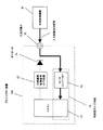
図1において、100は映像表示装置であるプロジェクター装置、102はスクリーン、110はスクリーン102を展開/収納するための展開収納装置、11はプロジェクター装置100と外部機器制御装置の制御回路であるマイコン、12は外部機器制御信号出力回路、13はA/Dコンバーター、14は入力制御信号と外部機器制御出力信号を分離するためのダイオード、15は制御信号の入出力端子である。また、16は制御信号入力回路であり、A/Dコンバーター13とマイコン11より構成されている。
In FIG. 1, 100 is a projector device that is a video display device, 102 is a screen, 110 is a deploying and storing device for deploying and storing the
以上のように構成された映像表示装置の外部機器制御装置についてその動作を説明する。 The operation of the external device control device of the video display device configured as described above will be described.
マイコン11はプロジェクター装置100が外部機器制御出力信号を出力させるモードに設定してあり、かつ、プロジェクター装置100が予め設定した動作状態であると判断したとき、外部機器制御信号出力回路12を制御して外部機器制御出力信号を出力させる。外部機器制御出力信号は入出力端子15を通って展開収納装置110に入力される。展開収納装置110は外部機器制御出力信号が入力されるとスクリーン102を展開する。
The microcomputer 11 controls the external device control
また、マイコン11はプロジェクター装置100が予め設定した動作状態でないと判断したとき、外部機器制御信号出力回路12を制御して外部機器制御出力信号の出力を停止させる。展開収納装置110は外部機器制御出力信号の入力が停止するとスクリーン102を収納する。
When the microcomputer 11 determines that the
このようにしてプロジェクター装置100よりスクリーン102の展開および収納を操作することができる。以上の動作は従来の映像表示機器の外部機器制御装置の動作と同様である。
In this way, the development and storage of the
ここで、外部機器制御出力信号を出力させたり停止させたりする「プロジェクター装置100の予め設定した動作状態」とは、例えば、プロジェクター装置100がONになっている状態であったり、特定の映像信号を受像している状態といった様に設計者が自由に決めることができる動作状態であり、特にプロジェクター装置100の動作状態が限定されるものではない。
Here, the “preset operation state of the
次に図2で本発明の実施例1に係る映像表示装置の外部機器制御装置を外部制御機器から制御する場合の動作を説明する。なお、図1と同じ構成要素には同一符号を付し、詳細な説明は省略する。 Next, the operation when the external device control device of the video display apparatus according to the first embodiment of the present invention is controlled from the external control device will be described with reference to FIG. The same components as those in FIG. 1 are denoted by the same reference numerals, and detailed description thereof is omitted.
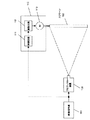
図2において、30はプロジェクター装置100の動作を外部より制御するための外部制御機器である。制御信号入力回路16はA/Dコンバーター13とマイコン11より構成されており、マイコン11はプロジェクター装置100が外部制御機器からの入力制御信号を入力するモードに設定してあるとき、外部制御機器30から入出力端子15に入力される入力制御信号をA/Dコンバーター13でデジタル信号に変換し、連続的に検出する。図2に示した構成の映像表示装置の外部機器制御装置では、外部機器制御出力信号の端子と入力制御信号の端子を入出力端子15で兼用している。そのため、入力制御信号が外部機器制御信号出力回路12に加わらないようにダイオード14で入力側と出力側の制御信号を分離している。
In FIG. 2,
マイコン11はA/Dコンバーター13で変換された入力制御信号が設定された条件になったときに、プロジェクター装置100を予め設定された動作状態にする。
When the input control signal converted by the A /
ここで、マイコン11が制御する「プロジェクター装置100を予め設定された動作状態」とは、例えば、プロジェクター装置100のランプの点灯制御や、映像信号のミュートや、入力信号の切り換えといった様に設計者が自由に決めることができる動作状態であり、特にプロジェクター装置100の動作が限定されるものではない。また、本発明の実施例1に係る映像表示装置の外部機器制御装置では、制御信号入力回路をA/Dコンバーターとマイコンを用いて構成するように説明したが、他の構成要素を用いて検出するようにしても問題はない。
Here, the “preset operation state of the
本発明の実施例1に係る映像表示装置の外部機器制御装置で制御信号出力回路と制御信号入力回路を複数組有する場合は、1つの制御信号出力回路と1つの制御信号入力回路を1組として、各々で外部機器に対する外部機器制御出力信号を発生する動作の実行および禁止と、外部機器より入力される入力制御信号によってプロジェクター装置100の動作を制御する動作の実行および禁止を独立に制御することができるように構成してある。
When the external device control device of the video display device according to the first embodiment of the present invention has a plurality of control signal output circuits and control signal input circuits, one control signal output circuit and one control signal input circuit are set as one set. Independently controlling the execution and prohibition of the operation for generating the external device control output signal for each external device and the execution and prohibition of the operation for controlling the operation of the
動作の実行および禁止の制御の方法としては、映像表示装置のメニューで選択するように構成することで容易に実現することができる。このように構成することで、1つの外部機器制御装置の回路の組みを出力に設定したときでも、他の回路の組みを入力に設定することができ、プロジェクター装置100を中心としたシステム構成の応用範囲を広めることができる。
The method for controlling the execution and prohibition of the operation can be easily realized by configuring the operation to be selected from the menu of the video display device. With this configuration, even when a circuit combination of one external device control device is set as an output, another circuit combination can be set as an input, and the system configuration centering on the
また、本発明の実施例1に係る映像表示装置の外部機器制御装置では、外部機器制御出力信号と入力制御信号の端子を兼用とした場合の構成について説明したが、これに限定される訳ではなく外部機器制御出力信号用と入力制御信号用にそれぞれ専用の端子を備えるように構成しても良い。 Further, in the external device control apparatus of the video display device according to the first embodiment of the present invention, the configuration in the case where the external device control output signal and the input control signal terminal are shared has been described, but the present invention is not limited to this. Alternatively, a dedicated terminal may be provided for each of the external device control output signal and the input control signal.
上記で説明したように映像表示装置の外部機器制御装置に制御信号出力機能に加えて制御信号入力機能を設けることで、外部よりプロジェクター装置の動作を制御できるようになるので、例えば、他の機器と一括してプロジェクター装置の電源のON/OFF制御ができるようになる。このように従来のスクリーンの展開/収納の制御だけでなく、照明やカーテン、プロジェクター装置の制御などといったシステム的な制御が可能になるので、使用者の利便性を大きく向上させることができる。 As described above, by providing a control signal input function in addition to the control signal output function in the external device control device of the video display device, the operation of the projector device can be controlled from the outside. It is possible to control the power supply of the projector device on and off. In this way, not only conventional screen expansion / storage control but also system control such as lighting, curtains, projector device control, and the like can be achieved, so that convenience for the user can be greatly improved.
(実施例2)
図3は本発明の実施例2に係る映像表示装置の外部機器制御装置の構成の一例を示した構成図である。図3では制御信号出力回路と制御信号入力回路を各1組有する場合の構成を示している。なお、図1と同じ構成要素には同一符号を付し、詳細な説明は省略する。
(Example 2)
FIG. 3 is a configuration diagram illustrating an example of the configuration of the external device control apparatus of the video display apparatus according to the second embodiment of the present invention. FIG. 3 shows a configuration in the case of having one set each of the control signal output circuit and the control signal input circuit. The same components as those in FIG. 1 are denoted by the same reference numerals, and detailed description thereof is omitted.
図3に示した映像表示装置の外部機器制御装置では、図1に示した映像表示装置の外部機器制御装置と同じ構成要素を用いた構成であるが、外部機器制御出力信号を出力するときに同時に制御信号入力回路16のA/Dコンバーター13を使ってマイコン11に外部機器制御出力信号を入力するように構成している。
The external device control device of the video display device shown in FIG. 3 has the same configuration as that of the external device control device of the video display device shown in FIG. 1, but when the external device control output signal is output. At the same time, the external device control output signal is input to the microcomputer 11 using the A /
外部機器制御信号出力回路12には接続する外部機器に対して定格が決められており、接続される外部機器が定格の範囲内であれば安全に使用することができる。ところが、使用者がどのような仕様の外部機器をプロジェクター装置100の入出力端子15に接続するかは分からない。もし、使用者が定格から外れた外部機器を接続した時、条件によっては外部機器制御信号出力回路12に過電流が流れるなどして、回路の破損などの事故につながる危険性がある。
The external device control
そこで、本発明の実施例2に係る映像表示装置の外部機器制御回路では、入力制御信号を検出する構成要素を利用して、外部機器制御信号出力回路12が外部機器制御出力信号を出力している間は、A/Dコンバーター13とマイコン11で外部機器制御出力信号状態を監視するように構成している。
Therefore, in the external device control circuit of the video display device according to the second embodiment of the present invention, the external device control
定格から外れた外部機器、例えば、入力インピーダンスが小さい外部機器を接続された場合は、外部機器制御出力信号の電圧が所定の電圧まで上がらずに電流だけが流れるので、外部機器制御信号出力回路12の電力損失が大きくなってしまう危険性がある。ここで、A/Dコンバーター13とマイコン11で外部機器制御出力信号の電圧値を監視することで、外部機器制御出力信号の電圧が所定の電圧まで上がっていないという異常な状態を検出することができる。
When an external device deviating from the rating, for example, an external device with a small input impedance is connected, only the current flows without the voltage of the external device control output signal rising to a predetermined voltage, so the external device control
マイコン11は外部機器制御出力信号が異常な状態であることを検出すると外部機器制御信号出力回路12に対して出力を停止するように制御するので、回路の破損などの事故を回避することができる。
When the microcomputer 11 detects that the external device control output signal is in an abnormal state, the microcomputer 11 controls the external device control
上記で説明したように映像表示装置の外部機器制御装置において、外部機器制御出力信号の出力時に外部機器制御出力信号の状態を監視するように構成することで、外部機器制御出力信号の異常な状態を検出することが可能となり、プロジェクター装置の信頼性を向上させることができる。また、本発明の実施例2では入力制御信号を検出する構成要素を利用して外部機器制御出力信号の状態を検出するように構成しているので、コストアップなしに実現できるという更なる効果もある。もちろん、外部機器制御出力信号の検出を専用の検出回路を用いて行うように構成しても良い。 As described above, in the external device control device of the video display device, an abnormal state of the external device control output signal is configured by monitoring the state of the external device control output signal when outputting the external device control output signal. Can be detected, and the reliability of the projector device can be improved. Further, since the second embodiment of the present invention is configured to detect the state of the external device control output signal using the component for detecting the input control signal, there is a further effect that it can be realized without increasing the cost. is there. Of course, the external device control output signal may be detected using a dedicated detection circuit.
本発明にかかる映像表示装置の外部機器制御装置は、制御信号出力機能に加えて制御信号入力機能を設けることで、外部よりプロジェクター装置の動作を制御できるようになって使用者の利便性を大きく向上させることができ、また、出力制御信号の異常状態を検出できる機能を設けることで、プロジェクター装置の信頼性を向上させることができるので、プロジェクター装置を中心としたホームシアターシステム構築時などの用途に有用である。 The external device control device of the video display device according to the present invention is provided with a control signal input function in addition to the control signal output function, so that the operation of the projector device can be controlled from the outside, which increases the convenience for the user. It is possible to improve the reliability of the projector device by providing a function that can detect the abnormal state of the output control signal, so it can be used for building a home theater system centered on the projector device. Useful.
11 マイコン
12 外部機器制御信号出力回路
13 A/Dコンバーター
14 ダイオード
15 入出力端子
16 制御信号入力回路
30 外部制御機器
100 プロジェクター装置
102 スクリーン
110 スクリーン102の展開収納装置
DESCRIPTION OF SYMBOLS 11
Claims (2)
前記外部機器制御信号出力回路が外部機器に対して制御信号を発生する動作の実行および禁止と、前記制御信号入力回路が外部機器より入力される制御信号によって前記映像表示装置の動作を制御する動作の実行および禁止を独立に制御することができ、
さらに、前記外部機器制御信号出力回路が外部機器に対して制御信号を出力している間は、前記制御信号入力回路で前記制御信号の状態を監視するように構成され、
前記制御信号が異常な状態になった時には、前記制御信号入力回路は、前記外部機器制御信号出力回路からの前記制御信号の出力を停止させることを特徴とする映像表示装置の外部機器制御装置。 A control device for an external device incorporated in a video display device, comprising at least one external device control signal output circuit and at least one control signal input circuit, wherein the video display device is set in advance. The external device control signal output circuit outputs a control signal to the external device, and the control signal input circuit detects the control signal input from the external device to operate the video display device. In the external device control device of the video display device to be controlled,
Execution and prohibition of an operation in which the external device control signal output circuit generates a control signal for the external device, and an operation in which the control signal input circuit controls the operation of the video display device by a control signal input from the external device Execution and prohibition can be controlled independently ,
Further, while the external device control signal output circuit is outputting a control signal to the external device, the control signal input circuit is configured to monitor the state of the control signal,
The external device control device of a video display device , wherein the control signal input circuit stops the output of the control signal from the external device control signal output circuit when the control signal becomes abnormal .
Priority Applications (3)
| Application Number | Priority Date | Filing Date | Title |
|---|---|---|---|
| JP2009236936A JP5434459B2 (en) | 2009-10-14 | 2009-10-14 | External device control device for video display device |
| CN2010105101443A CN102043311A (en) | 2009-10-14 | 2010-10-14 | Image display apparatus with external-equipment-link unit |
| US12/904,213 US20110085044A1 (en) | 2009-10-14 | 2010-10-14 | Image display apparatus with external-equipment-link unit |
Applications Claiming Priority (1)
| Application Number | Priority Date | Filing Date | Title |
|---|---|---|---|
| JP2009236936A JP5434459B2 (en) | 2009-10-14 | 2009-10-14 | External device control device for video display device |
Publications (3)
| Publication Number | Publication Date |
|---|---|
| JP2011085676A JP2011085676A (en) | 2011-04-28 |
| JP2011085676A5 JP2011085676A5 (en) | 2012-10-25 |
| JP5434459B2 true JP5434459B2 (en) | 2014-03-05 |
Family
ID=43854541
Family Applications (1)
| Application Number | Title | Priority Date | Filing Date |
|---|---|---|---|
| JP2009236936A Active JP5434459B2 (en) | 2009-10-14 | 2009-10-14 | External device control device for video display device |
Country Status (3)
| Country | Link |
|---|---|
| US (1) | US20110085044A1 (en) |
| JP (1) | JP5434459B2 (en) |
| CN (1) | CN102043311A (en) |
Families Citing this family (6)
| Publication number | Priority date | Publication date | Assignee | Title |
|---|---|---|---|---|
| CN102512792B (en) * | 2011-12-31 | 2014-01-22 | 哈尔滨师范大学 | Contact-type hockey shoot training device based on wireless transmission |
| CN102512802B (en) * | 2011-12-31 | 2014-01-22 | 哈尔滨师范大学 | Non-contact-type hockey shooting training device based on wireless transmission |
| KR102605035B1 (en) * | 2019-02-22 | 2023-11-24 | 삼성전자주식회사 | Electronic device comprising projector |
| CN112863409A (en) * | 2019-11-28 | 2021-05-28 | 中强光电股份有限公司 | Control method and system of projector |
| JP2022126436A (en) * | 2021-02-18 | 2022-08-30 | 富士フイルム株式会社 | Projection type display device |
| US11947243B2 (en) * | 2022-03-24 | 2024-04-02 | Changzhou Aac Raytech Optronics Co., Ltd. | Auto-focus apparatus for camera |
Family Cites Families (17)
| Publication number | Priority date | Publication date | Assignee | Title |
|---|---|---|---|---|
| US4188100A (en) * | 1976-05-24 | 1980-02-12 | Media Arts Workshop Inc. | Rotary slide carrier system |
| US6969960B2 (en) * | 1999-09-10 | 2005-11-29 | Belliveau Richard S | Image projection lighting device |
| JP4089106B2 (en) * | 1999-10-25 | 2008-05-28 | ソニー株式会社 | Projection display device, projection display system |
| JP3826659B2 (en) * | 2000-03-27 | 2006-09-27 | セイコーエプソン株式会社 | Projection display system and projection display device |
| US20040095562A1 (en) * | 2002-11-20 | 2004-05-20 | John Moffatt | Combination scanner/projector |
| US20060192927A1 (en) * | 2003-03-27 | 2006-08-31 | Toshio Ikeuchi | Display |
| JP3772870B2 (en) * | 2003-08-25 | 2006-05-10 | カシオ計算機株式会社 | Projection apparatus, projection method, and program |
| JP4527373B2 (en) * | 2003-09-04 | 2010-08-18 | Necディスプレイソリューションズ株式会社 | Video display device |
| US7393110B2 (en) * | 2004-07-06 | 2008-07-01 | Hewlett-Packard Development Company, L.P. | Media projector system |
| US7377658B2 (en) * | 2005-04-26 | 2008-05-27 | Dell Products L.P. | System and method for automated projector lamp management |
| KR100765267B1 (en) * | 2005-06-29 | 2007-10-09 | 삼성전자주식회사 | Electronic Apparatus, Control Method Thereof And Electronic Control System Comprising The Same |
| JP2007219164A (en) * | 2006-02-16 | 2007-08-30 | Seiko Epson Corp | Projecting device and program |
| US20070279593A1 (en) * | 2006-06-03 | 2007-12-06 | Weihua Li | Visual presenter with built-in central control system |
| JP2008083464A (en) * | 2006-09-28 | 2008-04-10 | Seiko Epson Corp | Projector system, projector, and screen apparatus |
| JP2008123138A (en) * | 2006-11-09 | 2008-05-29 | Seiko Epson Corp | Electronic equipment |
| JP5086632B2 (en) * | 2006-12-22 | 2012-11-28 | 株式会社東芝 | Video display device, video display system, and video display method |
| US7993006B2 (en) * | 2008-04-30 | 2011-08-09 | Dell Products L. P. | System and method for power control for information handling system peripherals |
-
2009
- 2009-10-14 JP JP2009236936A patent/JP5434459B2/en active Active
-
2010
- 2010-10-14 US US12/904,213 patent/US20110085044A1/en not_active Abandoned
- 2010-10-14 CN CN2010105101443A patent/CN102043311A/en active Pending
Also Published As
| Publication number | Publication date |
|---|---|
| US20110085044A1 (en) | 2011-04-14 |
| JP2011085676A (en) | 2011-04-28 |
| CN102043311A (en) | 2011-05-04 |
Similar Documents
| Publication | Publication Date | Title |
|---|---|---|
| JP5434459B2 (en) | External device control device for video display device | |
| US8899759B2 (en) | Projector and method for controlling the projector | |
| JP2005167774A (en) | Video image sound device | |
| KR100301512B1 (en) | Screen protection method in a video display | |
| JPWO2017126042A1 (en) | Projector and light source power switching method | |
| JP2008139771A (en) | Image display device, control method, control program, and recording medium | |
| JP2009239720A (en) | Electronic apparatus, and projector | |
| JP2007212619A (en) | Projection-type image display device | |
| KR20090063702A (en) | Signal processing apparatus and control method thereof | |
| JP2004328658A (en) | Video display unit and setup method for this video display unit | |
| KR100617088B1 (en) | Controller reset Apparatus | |
| JP2006080816A (en) | Television receiver | |
| JP4586497B2 (en) | Dimming control device | |
| JP2006258833A (en) | Projection type image display device | |
| JP2006254033A (en) | Television receiver | |
| KR20070093481A (en) | Method for displaying and switching external input in digital video device | |
| JP2006186705A (en) | Display device and method therefor, recording medium, and program | |
| JP2009025338A (en) | Projector and video projection method | |
| KR100586518B1 (en) | Display apparatus and control method thereof | |
| KR101001917B1 (en) | Apparatus for converting the external input apparatus of television | |
| KR100614310B1 (en) | Display device having auto after-image protection on pdp television and method using thereof | |
| JP2003280625A (en) | Display device | |
| KR100617087B1 (en) | Controller reset Apparatus | |
| JP2005333195A (en) | Video display apparatus | |
| KR200327488Y1 (en) | Apparatus for selecting video output in video machinery and tools |
Legal Events
| Date | Code | Title | Description |
|---|---|---|---|
| A521 | Request for written amendment filed |
Free format text: JAPANESE INTERMEDIATE CODE: A523 Effective date: 20120910 |
|
| A621 | Written request for application examination |
Free format text: JAPANESE INTERMEDIATE CODE: A621 Effective date: 20120910 |
|
| RD01 | Notification of change of attorney |
Free format text: JAPANESE INTERMEDIATE CODE: A7421 Effective date: 20121217 |
|
| A977 | Report on retrieval |
Free format text: JAPANESE INTERMEDIATE CODE: A971007 Effective date: 20130628 |
|
| A131 | Notification of reasons for refusal |
Free format text: JAPANESE INTERMEDIATE CODE: A131 Effective date: 20130709 |
|
| A521 | Request for written amendment filed |
Free format text: JAPANESE INTERMEDIATE CODE: A523 Effective date: 20130802 |
|
| TRDD | Decision of grant or rejection written | ||
| A01 | Written decision to grant a patent or to grant a registration (utility model) |
Free format text: JAPANESE INTERMEDIATE CODE: A01 Effective date: 20131112 |
|
| A61 | First payment of annual fees (during grant procedure) |
Free format text: JAPANESE INTERMEDIATE CODE: A61 Effective date: 20131125 |
|
| R151 | Written notification of patent or utility model registration |
Ref document number: 5434459 Country of ref document: JP Free format text: JAPANESE INTERMEDIATE CODE: R151 |