JP5431732B2 - Assay implementation in microfluidic format - Google Patents
Assay implementation in microfluidic format Download PDFInfo
- Publication number
- JP5431732B2 JP5431732B2 JP2008548875A JP2008548875A JP5431732B2 JP 5431732 B2 JP5431732 B2 JP 5431732B2 JP 2008548875 A JP2008548875 A JP 2008548875A JP 2008548875 A JP2008548875 A JP 2008548875A JP 5431732 B2 JP5431732 B2 JP 5431732B2
- Authority
- JP
- Japan
- Prior art keywords
- sample
- flow path
- light
- channel
- blood
- Prior art date
- Legal status (The legal status is an assumption and is not a legal conclusion. Google has not performed a legal analysis and makes no representation as to the accuracy of the status listed.)
- Active
Links
- 238000003556 assay Methods 0.000 title claims description 35
- 210000004369 blood Anatomy 0.000 claims description 143
- 239000008280 blood Substances 0.000 claims description 143
- 210000003743 erythrocyte Anatomy 0.000 claims description 102
- 210000000265 leukocyte Anatomy 0.000 claims description 85
- 239000012530 fluid Substances 0.000 claims description 71
- 238000003860 storage Methods 0.000 claims description 46
- 239000003153 chemical reaction reagent Substances 0.000 claims description 45
- 102000001554 Hemoglobins Human genes 0.000 claims description 44
- 108010054147 Hemoglobins Proteins 0.000 claims description 44
- 238000004163 cytometry Methods 0.000 claims description 43
- 239000002245 particle Substances 0.000 claims description 42
- 239000003219 hemolytic agent Substances 0.000 claims description 24
- 238000012360 testing method Methods 0.000 claims description 22
- 238000000034 method Methods 0.000 claims description 21
- 238000004820 blood count Methods 0.000 claims description 20
- 238000010521 absorption reaction Methods 0.000 claims description 19
- 239000007788 liquid Substances 0.000 claims description 16
- 239000002699 waste material Substances 0.000 claims description 14
- 238000003018 immunoassay Methods 0.000 claims description 9
- 238000005534 hematocrit Methods 0.000 claims description 8
- 230000008021 deposition Effects 0.000 claims description 7
- 230000004044 response Effects 0.000 claims description 4
- 239000003795 chemical substances by application Substances 0.000 claims description 3
- 238000004159 blood analysis Methods 0.000 claims description 2
- 238000004891 communication Methods 0.000 claims description 2
- 230000002934 lysing effect Effects 0.000 claims description 2
- 206010018910 Haemolysis Diseases 0.000 claims 1
- 108010006464 Hemolysin Proteins Proteins 0.000 claims 1
- 239000003228 hemolysin Substances 0.000 claims 1
- 230000008588 hemolysis Effects 0.000 claims 1
- 230000031700 light absorption Effects 0.000 claims 1
- 239000000523 sample Substances 0.000 description 127
- 210000004027 cell Anatomy 0.000 description 124
- 238000005259 measurement Methods 0.000 description 60
- 201000004792 malaria Diseases 0.000 description 46
- 238000013459 approach Methods 0.000 description 36
- 238000004458 analytical method Methods 0.000 description 32
- 230000003287 optical effect Effects 0.000 description 31
- 238000010586 diagram Methods 0.000 description 29
- 210000001772 blood platelet Anatomy 0.000 description 22
- 238000001514 detection method Methods 0.000 description 22
- 208000030507 AIDS Diseases 0.000 description 21
- 230000009089 cytolysis Effects 0.000 description 21
- 210000004698 lymphocyte Anatomy 0.000 description 19
- 241000894007 species Species 0.000 description 19
- 239000000463 material Substances 0.000 description 17
- 239000004033 plastic Substances 0.000 description 17
- 229920003023 plastic Polymers 0.000 description 17
- 239000000427 antigen Substances 0.000 description 16
- 230000006870 function Effects 0.000 description 14
- 239000003086 colorant Substances 0.000 description 13
- 102000036639 antigens Human genes 0.000 description 12
- 108091007433 antigens Proteins 0.000 description 12
- 230000008901 benefit Effects 0.000 description 12
- 238000000684 flow cytometry Methods 0.000 description 12
- 239000006166 lysate Substances 0.000 description 12
- 239000003550 marker Substances 0.000 description 12
- 238000012544 monitoring process Methods 0.000 description 12
- 229940079593 drug Drugs 0.000 description 10
- 239000003814 drug Substances 0.000 description 10
- 238000005563 spheronization Methods 0.000 description 10
- 101000738771 Homo sapiens Receptor-type tyrosine-protein phosphatase C Proteins 0.000 description 9
- 102100037422 Receptor-type tyrosine-protein phosphatase C Human genes 0.000 description 9
- 230000000875 corresponding effect Effects 0.000 description 9
- 238000000149 argon plasma sintering Methods 0.000 description 8
- 230000015572 biosynthetic process Effects 0.000 description 8
- 201000010099 disease Diseases 0.000 description 8
- 208000037265 diseases, disorders, signs and symptoms Diseases 0.000 description 8
- 239000011521 glass Substances 0.000 description 8
- 229920000089 Cyclic olefin copolymer Polymers 0.000 description 7
- 210000000601 blood cell Anatomy 0.000 description 7
- 230000008569 process Effects 0.000 description 7
- 201000008827 tuberculosis Diseases 0.000 description 7
- 239000004713 Cyclic olefin copolymer Substances 0.000 description 6
- 208000031886 HIV Infections Diseases 0.000 description 6
- 238000001917 fluorescence detection Methods 0.000 description 6
- 241000193738 Bacillus anthracis Species 0.000 description 5
- 208000037357 HIV infectious disease Diseases 0.000 description 5
- 241000223960 Plasmodium falciparum Species 0.000 description 5
- 230000009471 action Effects 0.000 description 5
- 238000003491 array Methods 0.000 description 5
- 239000011324 bead Substances 0.000 description 5
- 230000000994 depressogenic effect Effects 0.000 description 5
- 230000003760 hair shine Effects 0.000 description 5
- 208000033519 human immunodeficiency virus infectious disease Diseases 0.000 description 5
- 210000001616 monocyte Anatomy 0.000 description 5
- 210000000440 neutrophil Anatomy 0.000 description 5
- 238000002360 preparation method Methods 0.000 description 5
- 208000003322 Coinfection Diseases 0.000 description 4
- 238000004364 calculation method Methods 0.000 description 4
- 230000001276 controlling effect Effects 0.000 description 4
- 238000003745 diagnosis Methods 0.000 description 4
- 238000009826 distribution Methods 0.000 description 4
- 239000007850 fluorescent dye Substances 0.000 description 4
- 238000011534 incubation Methods 0.000 description 4
- 238000002372 labelling Methods 0.000 description 4
- 230000007246 mechanism Effects 0.000 description 4
- 238000000926 separation method Methods 0.000 description 4
- 239000000243 solution Substances 0.000 description 4
- 239000000758 substrate Substances 0.000 description 4
- 230000003612 virological effect Effects 0.000 description 4
- 241000894006 Bacteria Species 0.000 description 3
- 208000035473 Communicable disease Diseases 0.000 description 3
- 206010059484 Haemodilution Diseases 0.000 description 3
- XUIMIQQOPSSXEZ-UHFFFAOYSA-N Silicon Chemical compound [Si] XUIMIQQOPSSXEZ-UHFFFAOYSA-N 0.000 description 3
- 239000003146 anticoagulant agent Substances 0.000 description 3
- 229940127219 anticoagulant drug Drugs 0.000 description 3
- 230000004888 barrier function Effects 0.000 description 3
- 230000005540 biological transmission Effects 0.000 description 3
- 210000004970 cd4 cell Anatomy 0.000 description 3
- 230000006037 cell lysis Effects 0.000 description 3
- 230000001413 cellular effect Effects 0.000 description 3
- 230000008859 change Effects 0.000 description 3
- 238000010790 dilution Methods 0.000 description 3
- 239000012895 dilution Substances 0.000 description 3
- 238000001914 filtration Methods 0.000 description 3
- 125000001153 fluoro group Chemical group F* 0.000 description 3
- 238000004519 manufacturing process Methods 0.000 description 3
- 238000012986 modification Methods 0.000 description 3
- 230000004048 modification Effects 0.000 description 3
- 244000045947 parasite Species 0.000 description 3
- 229920000642 polymer Polymers 0.000 description 3
- 238000012545 processing Methods 0.000 description 3
- 239000010453 quartz Substances 0.000 description 3
- 230000035945 sensitivity Effects 0.000 description 3
- 239000010703 silicon Substances 0.000 description 3
- 229910052710 silicon Inorganic materials 0.000 description 3
- VYPSYNLAJGMNEJ-UHFFFAOYSA-N silicon dioxide Inorganic materials O=[Si]=O VYPSYNLAJGMNEJ-UHFFFAOYSA-N 0.000 description 3
- 238000010186 staining Methods 0.000 description 3
- 239000010409 thin film Substances 0.000 description 3
- XLYOFNOQVPJJNP-UHFFFAOYSA-N water Substances O XLYOFNOQVPJJNP-UHFFFAOYSA-N 0.000 description 3
- 210000000707 wrist Anatomy 0.000 description 3
- 108010029961 Filgrastim Proteins 0.000 description 2
- 206010028980 Neoplasm Diseases 0.000 description 2
- 210000001744 T-lymphocyte Anatomy 0.000 description 2
- 241000700605 Viruses Species 0.000 description 2
- 210000003651 basophil Anatomy 0.000 description 2
- 239000003124 biologic agent Substances 0.000 description 2
- 230000004071 biological effect Effects 0.000 description 2
- 239000010796 biological waste Substances 0.000 description 2
- 230000036770 blood supply Effects 0.000 description 2
- 239000000872 buffer Substances 0.000 description 2
- 201000011510 cancer Diseases 0.000 description 2
- 239000002575 chemical warfare agent Substances 0.000 description 2
- 238000002512 chemotherapy Methods 0.000 description 2
- 230000002596 correlated effect Effects 0.000 description 2
- 238000001035 drying Methods 0.000 description 2
- 238000005516 engineering process Methods 0.000 description 2
- 210000003979 eosinophil Anatomy 0.000 description 2
- 230000005284 excitation Effects 0.000 description 2
- 239000010408 film Substances 0.000 description 2
- 238000005194 fractionation Methods 0.000 description 2
- 230000009477 glass transition Effects 0.000 description 2
- 238000005286 illumination Methods 0.000 description 2
- 208000015181 infectious disease Diseases 0.000 description 2
- 238000013508 migration Methods 0.000 description 2
- 230000005012 migration Effects 0.000 description 2
- 238000002156 mixing Methods 0.000 description 2
- 239000000203 mixture Substances 0.000 description 2
- 229940029345 neupogen Drugs 0.000 description 2
- 238000004806 packaging method and process Methods 0.000 description 2
- 244000052769 pathogen Species 0.000 description 2
- 230000010287 polarization Effects 0.000 description 2
- 239000000843 powder Substances 0.000 description 2
- 230000005180 public health Effects 0.000 description 2
- 239000012898 sample dilution Substances 0.000 description 2
- 239000000126 substance Substances 0.000 description 2
- 210000003462 vein Anatomy 0.000 description 2
- 230000000007 visual effect Effects 0.000 description 2
- WKBPZYKAUNRMKP-UHFFFAOYSA-N 1-[2-(2,4-dichlorophenyl)pentyl]1,2,4-triazole Chemical compound C=1C=C(Cl)C=C(Cl)C=1C(CCC)CN1C=NC=N1 WKBPZYKAUNRMKP-UHFFFAOYSA-N 0.000 description 1
- RZVAJINKPMORJF-UHFFFAOYSA-N Acetaminophen Chemical compound CC(=O)NC1=CC=C(O)C=C1 RZVAJINKPMORJF-UHFFFAOYSA-N 0.000 description 1
- 229920004439 Aclar® Polymers 0.000 description 1
- 102100024222 B-lymphocyte antigen CD19 Human genes 0.000 description 1
- 102000004506 Blood Proteins Human genes 0.000 description 1
- 108010017384 Blood Proteins Proteins 0.000 description 1
- 206010063094 Cerebral malaria Diseases 0.000 description 1
- 238000001712 DNA sequencing Methods 0.000 description 1
- 206010059866 Drug resistance Diseases 0.000 description 1
- 102100031573 Hematopoietic progenitor cell antigen CD34 Human genes 0.000 description 1
- 241000282412 Homo Species 0.000 description 1
- 101000980825 Homo sapiens B-lymphocyte antigen CD19 Proteins 0.000 description 1
- 101100005713 Homo sapiens CD4 gene Proteins 0.000 description 1
- 101000777663 Homo sapiens Hematopoietic progenitor cell antigen CD34 Proteins 0.000 description 1
- 101100220215 Lineus sanguineus CDX gene Proteins 0.000 description 1
- 206010025323 Lymphomas Diseases 0.000 description 1
- OAICVXFJPJFONN-UHFFFAOYSA-N Phosphorus Chemical compound [P] OAICVXFJPJFONN-UHFFFAOYSA-N 0.000 description 1
- 241000224016 Plasmodium Species 0.000 description 1
- 239000004793 Polystyrene Substances 0.000 description 1
- 238000003559 RNA-seq method Methods 0.000 description 1
- NIXOWILDQLNWCW-UHFFFAOYSA-N acrylic acid group Chemical group C(C=C)(=O)O NIXOWILDQLNWCW-UHFFFAOYSA-N 0.000 description 1
- 239000000853 adhesive Substances 0.000 description 1
- 230000001070 adhesive effect Effects 0.000 description 1
- 230000000798 anti-retroviral effect Effects 0.000 description 1
- 238000013096 assay test Methods 0.000 description 1
- QVGXLLKOCUKJST-UHFFFAOYSA-N atomic oxygen Chemical compound [O] QVGXLLKOCUKJST-UHFFFAOYSA-N 0.000 description 1
- 230000001580 bacterial effect Effects 0.000 description 1
- 230000009286 beneficial effect Effects 0.000 description 1
- 239000012472 biological sample Substances 0.000 description 1
- BJQHLKABXJIVAM-UHFFFAOYSA-N bis(2-ethylhexyl) phthalate Chemical compound CCCCC(CC)COC(=O)C1=CC=CC=C1C(=O)OCC(CC)CCCC BJQHLKABXJIVAM-UHFFFAOYSA-N 0.000 description 1
- 230000000903 blocking effect Effects 0.000 description 1
- 238000009534 blood test Methods 0.000 description 1
- 230000001364 causal effect Effects 0.000 description 1
- 230000036755 cellular response Effects 0.000 description 1
- 210000001520 comb Anatomy 0.000 description 1
- 239000004020 conductor Substances 0.000 description 1
- 230000008878 coupling Effects 0.000 description 1
- 238000010168 coupling process Methods 0.000 description 1
- 238000005859 coupling reaction Methods 0.000 description 1
- 230000007423 decrease Effects 0.000 description 1
- 230000007123 defense Effects 0.000 description 1
- 238000013461 design Methods 0.000 description 1
- 238000011161 development Methods 0.000 description 1
- 238000009792 diffusion process Methods 0.000 description 1
- 239000003085 diluting agent Substances 0.000 description 1
- 239000006185 dispersion Substances 0.000 description 1
- 238000004090 dissolution Methods 0.000 description 1
- 238000002651 drug therapy Methods 0.000 description 1
- 239000000975 dye Substances 0.000 description 1
- 239000003792 electrolyte Substances 0.000 description 1
- 230000007613 environmental effect Effects 0.000 description 1
- 238000011156 evaluation Methods 0.000 description 1
- 238000009501 film coating Methods 0.000 description 1
- 238000002189 fluorescence spectrum Methods 0.000 description 1
- 238000004868 gas analysis Methods 0.000 description 1
- 210000003714 granulocyte Anatomy 0.000 description 1
- 230000036541 health Effects 0.000 description 1
- 230000002949 hemolytic effect Effects 0.000 description 1
- 230000001900 immune effect Effects 0.000 description 1
- 210000000987 immune system Anatomy 0.000 description 1
- 238000013394 immunophenotyping Methods 0.000 description 1
- 230000002458 infectious effect Effects 0.000 description 1
- 238000007689 inspection Methods 0.000 description 1
- 230000010354 integration Effects 0.000 description 1
- 238000002955 isolation Methods 0.000 description 1
- 239000002650 laminated plastic Substances 0.000 description 1
- 238000003475 lamination Methods 0.000 description 1
- 208000032839 leukemia Diseases 0.000 description 1
- 238000012423 maintenance Methods 0.000 description 1
- 239000002991 molded plastic Substances 0.000 description 1
- 230000000877 morphologic effect Effects 0.000 description 1
- 230000003039 myelosuppressive effect Effects 0.000 description 1
- 238000011017 operating method Methods 0.000 description 1
- 230000003204 osmotic effect Effects 0.000 description 1
- 239000001301 oxygen Substances 0.000 description 1
- 229910052760 oxygen Inorganic materials 0.000 description 1
- 230000003071 parasitic effect Effects 0.000 description 1
- 230000001717 pathogenic effect Effects 0.000 description 1
- 239000004038 photonic crystal Substances 0.000 description 1
- 239000002985 plastic film Substances 0.000 description 1
- 229920006255 plastic film Polymers 0.000 description 1
- 239000004417 polycarbonate Substances 0.000 description 1
- 229920000515 polycarbonate Polymers 0.000 description 1
- 239000005023 polychlorotrifluoroethylene (PCTFE) polymer Substances 0.000 description 1
- 229920002223 polystyrene Polymers 0.000 description 1
- 238000001485 positron annihilation lifetime spectroscopy Methods 0.000 description 1
- 238000004094 preconcentration Methods 0.000 description 1
- 230000002265 prevention Effects 0.000 description 1
- 230000003449 preventive effect Effects 0.000 description 1
- 238000007639 printing Methods 0.000 description 1
- 238000004393 prognosis Methods 0.000 description 1
- 102000004169 proteins and genes Human genes 0.000 description 1
- 108090000623 proteins and genes Proteins 0.000 description 1
- 244000000040 protozoan parasite Species 0.000 description 1
- 239000005297 pyrex Substances 0.000 description 1
- 238000010791 quenching Methods 0.000 description 1
- 230000000171 quenching effect Effects 0.000 description 1
- 230000000717 retained effect Effects 0.000 description 1
- 238000012216 screening Methods 0.000 description 1
- 238000007493 shaping process Methods 0.000 description 1
- 239000011550 stock solution Substances 0.000 description 1
- 208000024891 symptom Diseases 0.000 description 1
- 208000011580 syndromic disease Diseases 0.000 description 1
- 230000009897 systematic effect Effects 0.000 description 1
- 238000002560 therapeutic procedure Methods 0.000 description 1
- 238000002562 urinalysis Methods 0.000 description 1
- 238000005406 washing Methods 0.000 description 1
Images


Classifications
-
- G—PHYSICS
- G01—MEASURING; TESTING
- G01N—INVESTIGATING OR ANALYSING MATERIALS BY DETERMINING THEIR CHEMICAL OR PHYSICAL PROPERTIES
- G01N15/00—Investigating characteristics of particles; Investigating permeability, pore-volume, or surface-area of porous materials
- G01N15/10—Investigating individual particles
- G01N15/14—Electro-optical investigation, e.g. flow cytometers
- G01N15/1456—Electro-optical investigation, e.g. flow cytometers without spatial resolution of the texture or inner structure of the particle, e.g. processing of pulse signals
- G01N15/1459—Electro-optical investigation, e.g. flow cytometers without spatial resolution of the texture or inner structure of the particle, e.g. processing of pulse signals the analysis being performed on a sample stream
-
- B—PERFORMING OPERATIONS; TRANSPORTING
- B01—PHYSICAL OR CHEMICAL PROCESSES OR APPARATUS IN GENERAL
- B01L—CHEMICAL OR PHYSICAL LABORATORY APPARATUS FOR GENERAL USE
- B01L3/00—Containers or dishes for laboratory use, e.g. laboratory glassware; Droppers
- B01L3/50—Containers for the purpose of retaining a material to be analysed, e.g. test tubes
- B01L3/502—Containers for the purpose of retaining a material to be analysed, e.g. test tubes with fluid transport, e.g. in multi-compartment structures
- B01L3/5027—Containers for the purpose of retaining a material to be analysed, e.g. test tubes with fluid transport, e.g. in multi-compartment structures by integrated microfluidic structures, i.e. dimensions of channels and chambers are such that surface tension forces are important, e.g. lab-on-a-chip
- B01L3/502715—Containers for the purpose of retaining a material to be analysed, e.g. test tubes with fluid transport, e.g. in multi-compartment structures by integrated microfluidic structures, i.e. dimensions of channels and chambers are such that surface tension forces are important, e.g. lab-on-a-chip characterised by interfacing components, e.g. fluidic, electrical, optical or mechanical interfaces
-
- B—PERFORMING OPERATIONS; TRANSPORTING
- B01—PHYSICAL OR CHEMICAL PROCESSES OR APPARATUS IN GENERAL
- B01L—CHEMICAL OR PHYSICAL LABORATORY APPARATUS FOR GENERAL USE
- B01L3/00—Containers or dishes for laboratory use, e.g. laboratory glassware; Droppers
- B01L3/50—Containers for the purpose of retaining a material to be analysed, e.g. test tubes
- B01L3/502—Containers for the purpose of retaining a material to be analysed, e.g. test tubes with fluid transport, e.g. in multi-compartment structures
- B01L3/5027—Containers for the purpose of retaining a material to be analysed, e.g. test tubes with fluid transport, e.g. in multi-compartment structures by integrated microfluidic structures, i.e. dimensions of channels and chambers are such that surface tension forces are important, e.g. lab-on-a-chip
- B01L3/502769—Containers for the purpose of retaining a material to be analysed, e.g. test tubes with fluid transport, e.g. in multi-compartment structures by integrated microfluidic structures, i.e. dimensions of channels and chambers are such that surface tension forces are important, e.g. lab-on-a-chip characterised by multiphase flow arrangements
- B01L3/502776—Containers for the purpose of retaining a material to be analysed, e.g. test tubes with fluid transport, e.g. in multi-compartment structures by integrated microfluidic structures, i.e. dimensions of channels and chambers are such that surface tension forces are important, e.g. lab-on-a-chip characterised by multiphase flow arrangements specially adapted for focusing or laminating flows
-
- G—PHYSICS
- G01—MEASURING; TESTING
- G01N—INVESTIGATING OR ANALYSING MATERIALS BY DETERMINING THEIR CHEMICAL OR PHYSICAL PROPERTIES
- G01N15/00—Investigating characteristics of particles; Investigating permeability, pore-volume, or surface-area of porous materials
- G01N15/10—Investigating individual particles
- G01N15/14—Electro-optical investigation, e.g. flow cytometers
- G01N15/1484—Electro-optical investigation, e.g. flow cytometers microstructural devices
-
- G—PHYSICS
- G01—MEASURING; TESTING
- G01N—INVESTIGATING OR ANALYSING MATERIALS BY DETERMINING THEIR CHEMICAL OR PHYSICAL PROPERTIES
- G01N33/00—Investigating or analysing materials by specific methods not covered by groups G01N1/00 - G01N31/00
- G01N33/48—Biological material, e.g. blood, urine; Haemocytometers
- G01N33/50—Chemical analysis of biological material, e.g. blood, urine; Testing involving biospecific ligand binding methods; Immunological testing
- G01N33/5005—Chemical analysis of biological material, e.g. blood, urine; Testing involving biospecific ligand binding methods; Immunological testing involving human or animal cells
- G01N33/5094—Chemical analysis of biological material, e.g. blood, urine; Testing involving biospecific ligand binding methods; Immunological testing involving human or animal cells for blood cell populations
-
- B—PERFORMING OPERATIONS; TRANSPORTING
- B01—PHYSICAL OR CHEMICAL PROCESSES OR APPARATUS IN GENERAL
- B01L—CHEMICAL OR PHYSICAL LABORATORY APPARATUS FOR GENERAL USE
- B01L2200/00—Solutions for specific problems relating to chemical or physical laboratory apparatus
- B01L2200/06—Fluid handling related problems
- B01L2200/0636—Focussing flows, e.g. to laminate flows
-
- B—PERFORMING OPERATIONS; TRANSPORTING
- B01—PHYSICAL OR CHEMICAL PROCESSES OR APPARATUS IN GENERAL
- B01L—CHEMICAL OR PHYSICAL LABORATORY APPARATUS FOR GENERAL USE
- B01L2200/00—Solutions for specific problems relating to chemical or physical laboratory apparatus
- B01L2200/06—Fluid handling related problems
- B01L2200/0647—Handling flowable solids, e.g. microscopic beads, cells, particles
-
- B—PERFORMING OPERATIONS; TRANSPORTING
- B01—PHYSICAL OR CHEMICAL PROCESSES OR APPARATUS IN GENERAL
- B01L—CHEMICAL OR PHYSICAL LABORATORY APPARATUS FOR GENERAL USE
- B01L2200/00—Solutions for specific problems relating to chemical or physical laboratory apparatus
- B01L2200/06—Fluid handling related problems
- B01L2200/0684—Venting, avoiding backpressure, avoid gas bubbles
-
- B—PERFORMING OPERATIONS; TRANSPORTING
- B01—PHYSICAL OR CHEMICAL PROCESSES OR APPARATUS IN GENERAL
- B01L—CHEMICAL OR PHYSICAL LABORATORY APPARATUS FOR GENERAL USE
- B01L2200/00—Solutions for specific problems relating to chemical or physical laboratory apparatus
- B01L2200/10—Integrating sample preparation and analysis in single entity, e.g. lab-on-a-chip concept
-
- B—PERFORMING OPERATIONS; TRANSPORTING
- B01—PHYSICAL OR CHEMICAL PROCESSES OR APPARATUS IN GENERAL
- B01L—CHEMICAL OR PHYSICAL LABORATORY APPARATUS FOR GENERAL USE
- B01L2200/00—Solutions for specific problems relating to chemical or physical laboratory apparatus
- B01L2200/14—Process control and prevention of errors
- B01L2200/143—Quality control, feedback systems
- B01L2200/146—Employing pressure sensors
-
- B—PERFORMING OPERATIONS; TRANSPORTING
- B01—PHYSICAL OR CHEMICAL PROCESSES OR APPARATUS IN GENERAL
- B01L—CHEMICAL OR PHYSICAL LABORATORY APPARATUS FOR GENERAL USE
- B01L2300/00—Additional constructional details
- B01L2300/08—Geometry, shape and general structure
- B01L2300/0809—Geometry, shape and general structure rectangular shaped
- B01L2300/0816—Cards, e.g. flat sample carriers usually with flow in two horizontal directions
-
- B—PERFORMING OPERATIONS; TRANSPORTING
- B01—PHYSICAL OR CHEMICAL PROCESSES OR APPARATUS IN GENERAL
- B01L—CHEMICAL OR PHYSICAL LABORATORY APPARATUS FOR GENERAL USE
- B01L2300/00—Additional constructional details
- B01L2300/08—Geometry, shape and general structure
- B01L2300/0861—Configuration of multiple channels and/or chambers in a single devices
- B01L2300/0867—Multiple inlets and one sample wells, e.g. mixing, dilution
-
- B—PERFORMING OPERATIONS; TRANSPORTING
- B01—PHYSICAL OR CHEMICAL PROCESSES OR APPARATUS IN GENERAL
- B01L—CHEMICAL OR PHYSICAL LABORATORY APPARATUS FOR GENERAL USE
- B01L2300/00—Additional constructional details
- B01L2300/08—Geometry, shape and general structure
- B01L2300/0861—Configuration of multiple channels and/or chambers in a single devices
- B01L2300/087—Multiple sequential chambers
-
- B—PERFORMING OPERATIONS; TRANSPORTING
- B01—PHYSICAL OR CHEMICAL PROCESSES OR APPARATUS IN GENERAL
- B01L—CHEMICAL OR PHYSICAL LABORATORY APPARATUS FOR GENERAL USE
- B01L2300/00—Additional constructional details
- B01L2300/08—Geometry, shape and general structure
- B01L2300/0887—Laminated structure
-
- B—PERFORMING OPERATIONS; TRANSPORTING
- B01—PHYSICAL OR CHEMICAL PROCESSES OR APPARATUS IN GENERAL
- B01L—CHEMICAL OR PHYSICAL LABORATORY APPARATUS FOR GENERAL USE
- B01L2400/00—Moving or stopping fluids
- B01L2400/04—Moving fluids with specific forces or mechanical means
- B01L2400/0475—Moving fluids with specific forces or mechanical means specific mechanical means and fluid pressure
- B01L2400/0487—Moving fluids with specific forces or mechanical means specific mechanical means and fluid pressure fluid pressure, pneumatics
-
- B—PERFORMING OPERATIONS; TRANSPORTING
- B01—PHYSICAL OR CHEMICAL PROCESSES OR APPARATUS IN GENERAL
- B01L—CHEMICAL OR PHYSICAL LABORATORY APPARATUS FOR GENERAL USE
- B01L9/00—Supporting devices; Holding devices
- B01L9/52—Supports specially adapted for flat sample carriers, e.g. for plates, slides, chips
- B01L9/527—Supports specially adapted for flat sample carriers, e.g. for plates, slides, chips for microfluidic devices, e.g. used for lab-on-a-chip
-
- G01N2015/012—
-
- G01N2015/016—
-
- G01N2015/018—
-
- G01N2015/019—
-
- G—PHYSICS
- G01—MEASURING; TESTING
- G01N—INVESTIGATING OR ANALYSING MATERIALS BY DETERMINING THEIR CHEMICAL OR PHYSICAL PROPERTIES
- G01N15/00—Investigating characteristics of particles; Investigating permeability, pore-volume, or surface-area of porous materials
- G01N15/10—Investigating individual particles
- G01N15/14—Electro-optical investigation, e.g. flow cytometers
- G01N2015/1486—Counting the particles
-
- G—PHYSICS
- G01—MEASURING; TESTING
- G01N—INVESTIGATING OR ANALYSING MATERIALS BY DETERMINING THEIR CHEMICAL OR PHYSICAL PROPERTIES
- G01N35/00—Automatic analysis not limited to methods or materials provided for in any single one of groups G01N1/00 - G01N33/00; Handling materials therefor
- G01N35/00029—Automatic analysis not limited to methods or materials provided for in any single one of groups G01N1/00 - G01N33/00; Handling materials therefor provided with flat sample substrates, e.g. slides
- G01N2035/00099—Characterised by type of test elements
- G01N2035/00158—Elements containing microarrays, i.e. "biochip"
-
- G—PHYSICS
- G01—MEASURING; TESTING
- G01N—INVESTIGATING OR ANALYSING MATERIALS BY DETERMINING THEIR CHEMICAL OR PHYSICAL PROPERTIES
- G01N2333/00—Assays involving biological materials from specific organisms or of a specific nature
- G01N2333/435—Assays involving biological materials from specific organisms or of a specific nature from animals; from humans
- G01N2333/44—Assays involving biological materials from specific organisms or of a specific nature from animals; from humans from protozoa
- G01N2333/445—Plasmodium
-
- G—PHYSICS
- G01—MEASURING; TESTING
- G01N—INVESTIGATING OR ANALYSING MATERIALS BY DETERMINING THEIR CHEMICAL OR PHYSICAL PROPERTIES
- G01N2333/00—Assays involving biological materials from specific organisms or of a specific nature
- G01N2333/435—Assays involving biological materials from specific organisms or of a specific nature from animals; from humans
- G01N2333/705—Assays involving receptors, cell surface antigens or cell surface determinants
- G01N2333/70503—Immunoglobulin superfamily, e.g. VCAMs, PECAM, LFA-3
- G01N2333/70514—CD4
-
- G—PHYSICS
- G01—MEASURING; TESTING
- G01N—INVESTIGATING OR ANALYSING MATERIALS BY DETERMINING THEIR CHEMICAL OR PHYSICAL PROPERTIES
- G01N2333/00—Assays involving biological materials from specific organisms or of a specific nature
- G01N2333/435—Assays involving biological materials from specific organisms or of a specific nature from animals; from humans
- G01N2333/705—Assays involving receptors, cell surface antigens or cell surface determinants
- G01N2333/70589—CD45
-
- G—PHYSICS
- G01—MEASURING; TESTING
- G01N—INVESTIGATING OR ANALYSING MATERIALS BY DETERMINING THEIR CHEMICAL OR PHYSICAL PROPERTIES
- G01N2800/00—Detection or diagnosis of diseases
- G01N2800/26—Infectious diseases, e.g. generalised sepsis
-
- Y—GENERAL TAGGING OF NEW TECHNOLOGICAL DEVELOPMENTS; GENERAL TAGGING OF CROSS-SECTIONAL TECHNOLOGIES SPANNING OVER SEVERAL SECTIONS OF THE IPC; TECHNICAL SUBJECTS COVERED BY FORMER USPC CROSS-REFERENCE ART COLLECTIONS [XRACs] AND DIGESTS
- Y02—TECHNOLOGIES OR APPLICATIONS FOR MITIGATION OR ADAPTATION AGAINST CLIMATE CHANGE
- Y02A—TECHNOLOGIES FOR ADAPTATION TO CLIMATE CHANGE
- Y02A50/00—TECHNOLOGIES FOR ADAPTATION TO CLIMATE CHANGE in human health protection, e.g. against extreme weather
- Y02A50/30—Against vector-borne diseases, e.g. mosquito-borne, fly-borne, tick-borne or waterborne diseases whose impact is exacerbated by climate change
-
- Y—GENERAL TAGGING OF NEW TECHNOLOGICAL DEVELOPMENTS; GENERAL TAGGING OF CROSS-SECTIONAL TECHNOLOGIES SPANNING OVER SEVERAL SECTIONS OF THE IPC; TECHNICAL SUBJECTS COVERED BY FORMER USPC CROSS-REFERENCE ART COLLECTIONS [XRACs] AND DIGESTS
- Y10—TECHNICAL SUBJECTS COVERED BY FORMER USPC
- Y10T—TECHNICAL SUBJECTS COVERED BY FORMER US CLASSIFICATION
- Y10T436/00—Chemistry: analytical and immunological testing
- Y10T436/25—Chemistry: analytical and immunological testing including sample preparation
- Y10T436/2575—Volumetric liquid transfer
Description
本出願は、2005年12月29日に出願した米国仮特許出願第60/755,014号の利益を主張する。
本出願は、2005年12月22日に出願した米国仮特許出願第60/753,293号の利益を主張する、2006年12月22日に出願した米国特許出願第11/615,884号の一部継続出願である。
This application claims the benefit of US Provisional Patent Application No. 60 / 755,014, filed Dec. 29, 2005.
This application claims the benefit of US Provisional Patent Application No. 60 / 753,293, filed Dec. 22, 2005, which is the benefit of U.S. Patent Application No. 11 / 615,884, filed Dec. 22, 2006. Partial continuation application.
本出願は、2004年5月14日に出願した仮特許出願第60/571,235号の利益を主張する、2005年5月12日に出願した米国特許出願第10/908,460号の一部継続出願である。
This application is one of US patent application Ser. No. 10 / 908,460, filed May 12, 2005, which claims the benefit of
本出願は、2004年5月14日に出願した仮特許出願第60/571,235号の利益を主張する、2005年5月12日に出願した米国特許出願第10/908,461号の一部継続出願である。
This application is one of US patent application Ser. No. 10 / 908,461, filed May 12, 2005, which claims the benefit of
本出願は、2004年9月27日に出願した米国特許出願第10/950,898号の一部継続出願である、2005年12月30日に出願した米国特許出願第11/306,508号の一部継続出願である。 This application is a continuation-in-part of US patent application Ser. No. 10 / 950,898, filed Sep. 27, 2004, and US Patent Application No. 11 / 306,508, filed Dec. 30, 2005. Is a continuation-in-part application.
本出願は、2002年11月26日に出願した米国特許出願第10/304,773号の一部継続出願である、2004年9月9日に出願した米国特許出願第10/938,265号の一部継続出願である。 This application is a continuation-in-part of US patent application Ser. No. 10 / 304,773, filed on Nov. 26, 2002, and US patent application Ser. Is a continuation-in-part application.
本発明は、サイトメトリー、特に携帯型サイトメトリーに関するものである。より具体的には、本発明は、血液分析に関する。 The present invention relates to cytometry, particularly portable cytometry. More specifically, the present invention relates to blood analysis.
HIVおよびマラリアは、死亡率と疾病率のいくつかの主要原因のうちの2つであり、それぞれ、即座の診断と効果的な治療で予防可能である。これらの疾病は両方とも全世界の途方もない負担となっているが、これが発生しているのがサハラ砂漠以南のアフリカである。マラリア原虫血症の有病率は、HIV感染とともに増大し、マラリアの発生率は、HIV感染とともに増大し、HIVは、マラリア患者が重度のマラリアを発症する危険性を増大し、マラリア予防または治療はHIV重感染に対しては有効性が低い場合があることを示唆する証拠が挙げられている。HIVを監視する場合、注目するマーカーは、CD4+リンパ球であり、CD4枯渇は、HIV疾病の発病に直接リンクしているように見える。 HIV and malaria are two of several major causes of mortality and morbidity, each of which can be prevented with immediate diagnosis and effective treatment. Both of these diseases are a tremendous burden worldwide, but it occurs in sub-Saharan Africa. The prevalence of protozoal malaria increases with HIV infection, the incidence of malaria increases with HIV infection, and HIV increases the risk of malaria patients developing severe malaria, preventing or treating malaria Evidence suggests that may be less effective against HIV co-infection. When monitoring HIV, the marker of interest is CD4 + lymphocytes, and CD4 depletion appears to be directly linked to the onset of HIV disease.
全白血球数またはリンパ球数の変動は、ヒトのCD4数に影響を及ぼす可能性があることに留意されたい。これは、変化の少ないCD4パーセンテージについて話すのを好む人たちもいるからである。 It should be noted that fluctuations in total white blood cell count or lymphocyte count can affect human CD4 count. This is because some people prefer to talk about the percentage of CD4 with little change.
完全血球算定(CBC)を指令すると、ヘマトクリットおよびヘモグロビン(赤血球に関する情報が得られる)と白血球数を求めることができる。「分画」は、異なる種類の白血球を、また好中球、リンパ球、単球、好酸球、好塩基球のパーセンテージを示すことができる。HIVで注目するのは、リンパ球である。 When complete blood count (CBC) is commanded, hematocrit and hemoglobin (information on red blood cells can be obtained) and white blood cell count can be obtained. “Fraction” can indicate different types of white blood cells and also the percentage of neutrophils, lymphocytes, monocytes, eosinophils, basophils. It is lymphocytes to pay attention to in HIV.
T細胞数(CD3数)は、CD4数およびCD8数を含むことができる。比CD4/CD8は、もはや頻繁には使用されないであろう。これらの測定に対し、高い数値が最良であるように見えるが、ウイルス量、絶対数のCD4数、およびCD4パーセンテージに注意を払うことによりある種の混同を避け、比CD4/CD8を無視することができる。 The T cell count (CD3 count) can include CD4 count and CD8 count. The ratio CD4 / CD8 will no longer be used frequently. For these measurements, high numbers appear to be best, but avoid some kind of confusion by ignoring the viral load, absolute CD4 count, and CD4 percentage, and ignore the ratio CD4 / CD8 Can do.
CD+4(Tヘルパーともいう)リンパ球は、人体の免疫学的防御に関与している可能性がある。HIV感染によりそれが喪失すると、免疫系が徐々に低下し、後天性免疫不全症候群(AIDS)に関連する症状に進行する可能性がある。治療ガイドラインでは、抗レトロウイルス薬物療法をいつ開始すべきかを決定すること、治療計画がどれだけよく働いているかを評価すること、および代替え投薬計画への切り換えが必要かどうかを決定するのを補助することのために定量的CD4+リンパ球およびHIVウイルス量検査を使用する必要がある場合がある。 CD + 4 (also called T helper) lymphocytes may be involved in the human body's immunological defenses. When it is lost due to HIV infection, the immune system may gradually decline and progress to symptoms associated with acquired immune deficiency syndrome (AIDS). Treatment guidelines help determine when to start antiretroviral drug therapy, evaluate how well the treatment plan is working, and determine if switching to an alternative dosing plan is required It may be necessary to use quantitative CD4 + lymphocytes and HIV viral load test to do so.
開発途上国のHIV感染者が増加の一途を辿り、ヘルスケアサービスに過度の負担をかけ、圧倒し続ける。大半の開発途上国では、既存の検査方法があまりにも高価で複雑であるため、HIV感染者のCD4+リンパ球数を監視する既存の施設は、限られているか、または存在していない。CD4+リンパ球を監視するための単純で、安価で、半定量的なアプローチが利用可能であれば、以下の疾病および公衆衛生への影響が生じうる。CD4+リンパ球レベルを検査し、監視するための簡素化された、低コストの、使いやすいデバイスを実現すると、CD4検査をふつうに、一貫して利用することが可能になり、これによりHIV治療の有効性が高まり、薬剤耐性が低減されるが、これは開発途上国世界においては非常に価値のあることと思われる。 The number of people living with HIV in developing countries continues to increase, overloading healthcare services and continuing to overwhelm. In most developing countries, existing testing methods for monitoring CD4 + lymphocyte counts in HIV-infected persons are limited or nonexistent because existing testing methods are too expensive and complex. If a simple, inexpensive, semi-quantitative approach for monitoring CD4 + lymphocytes is available, the following disease and public health impacts can occur. Realizing a simplified, low-cost, easy-to-use device for testing and monitoring CD4 + lymphocyte levels will allow CD4 testing to be used consistently and in general for HIV treatment. Increased effectiveness and reduced drug resistance, which appears to be very valuable in the developing world.
マラリアによる感染の早期の正確な診断は、効果的な疾病管理には重要であり、また脳マラリアなどの合併症の進行と発症を防ぐのにも重要である。マラリアの2つの最も伝染力の強い普通種は、熱帯熱マラリア原虫(P)および三日熱マラリア原虫であり、したがって、安価で、使いやすいデバイスを介してこれら2つの種を同定できれば、開発途上国世界にとって大いに有益であろう。 Early and accurate diagnosis of malaria infection is important for effective disease management and also for preventing the progression and onset of complications such as cerebral malaria. The two most contagious common species of malaria are Plasmodium falciparum (P) and Plasmodium falciparum, so if these two species can be identified through cheap, easy-to-use devices, It will be very beneficial for the country world.
2005年12月22日に出願された米国仮特許出願第60/753,293号は、参照により本明細書に組み込まれる。2005年12月29日に出願された米国仮特許出願第60/755,014号は、参照により本明細書に組み込まれる。2005年5月12日に出願された米国特許出願第10/908,460号は、参照により本明細書に組み込まれる。2005年5月12日に出願された米国特許出願第10/908,461号は、参照により本明細書に組み込まれる。2005年12月30日に出願された米国特許出願第11/306,508号は、参照により本明細書に組み込まれる。2004年9月27日に出願された米国特許出願第10/950,898号の一部継続出願は、参照により本明細書に組み込まれる。2004年9月9日に出願された米国特許出願第10/938,265号は、参照により本明細書に組み込まれる。 US Provisional Patent Application No. 60 / 753,293, filed December 22, 2005, is hereby incorporated by reference. US Provisional Patent Application No. 60 / 755,014, filed December 29, 2005, is hereby incorporated by reference. US patent application Ser. No. 10 / 908,460, filed May 12, 2005, is hereby incorporated by reference. US patent application Ser. No. 10 / 908,461, filed May 12, 2005, is hereby incorporated by reference. US patent application Ser. No. 11 / 306,508, filed Dec. 30, 2005, is hereby incorporated by reference. The continuation-in-part of US patent application Ser. No. 10 / 950,898, filed Sep. 27, 2004, is hereby incorporated by reference. US patent application Ser. No. 10 / 938,265, filed Sep. 9, 2004, is hereby incorporated by reference.
本発明は、1つのポイントオブケア(POC)マイクロ流体計測装置プラットフォームで免疫アッセイおよび血液学検査を行うことができる装置である。 The present invention is an apparatus capable of performing immunoassays and hematology tests on a single point-of-care (POC) microfluidic instrument platform.
診断、監視、および生命科学の用途向けのポイントオブケア(POC)計測装置の需要が増大している。POCフローサイトメーターの重要な用途の1つは、投薬(ART)中のAIDS(HIV感染)患者および他の疾病を患っている患者を含む他の患者を監視することである。フローサイトメーターは、マイクロ流体フォーマットでこれらのアッセイを実施する。 There is an increasing demand for point-of-care (POC) measurement devices for diagnostic, monitoring, and life science applications. One important use of POC flow cytometers is to monitor other patients, including AIDS (HIV-infected) patients on medication (ART) and patients suffering from other diseases. Flow cytometers perform these assays in a microfluidic format.
本発明は、ポイントオブケア計測装置用にCD4/CD8/CDXXアッセイ(HIV感染患者に使用される)を実施するアプローチを実現する。このアッセイは、使い捨て型プラスチック製分析カードのマイクロ流体フォーマットで実装されうる。カードは、CDXXアッセイを実行することができるだけでなく、さらに総白血球数/白血球分画の検査も実行できる。本発明は、単一のマイクロ流体カートリッジ上で組み合わせることができるそれぞれのモジュールとなっている2つの検査(CDXX検査または免疫アッセイ検査および血液学検査)を実施することができる。カートリッジは、積層構造であるか、または少なくとも部分的には、成形構造としてよい。カートリッジの材料としては、さまざまなタイプのプラスチックおよびガラス材料が考えられる。他の材料も、例えば、埋め込まれる電極などの特定の電気的コンポーネントに対する導電性材料などを適宜構造の中に使用できる。 The present invention provides an approach to performing a CD4 / CD8 / CDXX assay (used for HIV infected patients) for point-of-care instrumentation. The assay can be implemented in a microfluidic format on a disposable plastic analysis card. The card can not only perform a CDXX assay, but can also perform a total white blood cell count / white blood cell fraction test. The present invention can perform two tests (CDXX test or immunoassay test and hematology test) that are each module that can be combined on a single microfluidic cartridge. The cartridge may be a laminated structure or at least partially a molded structure. Various types of plastic and glass materials can be considered as the material of the cartridge. Other materials can also be used in the structure as appropriate, such as, for example, conductive materials for specific electrical components such as embedded electrodes.
マイクロ流体フォーマットのいくつかの利点として、試薬消費量が最小である(したがって、検査コストが低い)、両方の検査が同じカード上で実行されるため使いやすい、試料調製手順が簡素化されている(30分間のインキュベーションがない)などが挙げられる。本発明は、マイクロ流体カートリッジ上にマイクロ流体フォーマットで異なるアッセイ機能を実装することを含むことができる。これらの機能は、混合、分離、濾過、洗浄、予備濃縮、溶解、選別などを含むことができる。 Some advantages of the microfluidic format are simpler sample preparation procedures, with minimal reagent consumption (and thus lower test costs), easier to use because both tests are performed on the same card (No incubation for 30 minutes). The present invention can include implementing different assay functions in a microfluidic format on a microfluidic cartridge. These functions can include mixing, separation, filtration, washing, preconcentration, dissolution, sorting, and the like.
本発明は、白血球試料入力から得られた白血球を計数し、分類することができるPOC統合散乱および蛍光フローサイトメーターとしてよい。本発明のPOC計測装置は、CD4監視(CD4絶対数およびパーセントCD4)に使用されうる。このサイトメーターは、ハンドヘルド型計測装置およびクレジットカードサイズの使い捨て型分析カートリッジで構成することができる。使い捨て型カートリッジは、オンボード試薬貯蔵容器(希釈液、溶解液、およびシース液)、全血試料捕捉毛細管、およびオンボード液流センサーを備えることができる。サイトメーターシステムは、カートリッジ上の自動化試料調製機能、赤色VCSEL配列ベース電子セルフアライメント機能、超小型3流路ポンプシステム、ならびにカスタム開発電子回路およびグラフィカルユーザーインターフェイスを備えることができる。 The present invention may be a POC integrated scatter and fluorescence flow cytometer capable of counting and classifying leukocytes obtained from leukocyte sample inputs. The POC measurement device of the present invention can be used for CD4 monitoring (CD4 absolute number and percent CD4). The cytometer can be composed of a handheld measuring device and a credit card size disposable analysis cartridge. The disposable cartridge can include an on-board reagent storage container (diluent, lysate, and sheath fluid), a whole blood sample capture capillary, and an on-board fluid flow sensor. The cytometer system can include automated sample preparation on the cartridge, red VCSEL array-based electronic self-alignment, a micro three-channel pump system, and custom developed electronics and a graphical user interface.
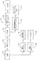
図1は、ポイントオブケア(POC)計測装置およびその動作のブロック図である。全血試料は、ブロック111で持ち込むことができる。全血の一部は、溶解ウェル112に通され、そこで主にブロック113で白血球を得るために赤血球を除去することができる。白血球の一部は、ブロック114で散乱ベースサイトメトリーに入り、その結果、ブロック115で白血球の個数と5分画が得られる。
FIG. 1 is a block diagram of a point-of-care (POC) measuring device and its operation. Whole blood samples can be brought in at
ブロック113から、一部の白血球は、さらに、蛍光標識抗体でインキュベートするためにブロック116に入ることができる。これは、ブロック117で、CD4、CD、マラリア寄生体、結核(TB)などの指標および/または量に関する情報を得るためである。
From
さらにブロック111からは、全血一部が、散乱およびサイトメトリーブロック118に入り、RBC数とヘマトクリットデータを取得することができる。ここでもまた、ブロック111から、全血はブロック120に入り、血液中のヘモグロビンの量に関する溶解および吸収ベースの情報得ることができる。図1のブロック内の項目は、マイクロ流体カートリッジまたはカード上で実装することができ、血液学分析器とみなすことができる。カートリッジの主な目標の1つは、赤血球数、白血球数、ヘモグロビン量、ヘマトクリットデータ、血小板数、および白血球の5分画を含むことができる完全血球算定パラメータを得ることである。ブロック115、119、および121では、完全血球算定を行うことができる。ブロック117は、蛍光で分析を行うことができる。2つの主要な操作は、通常のクレジットカードほどの小ささで、使い捨てのマイクロ流体カートリッジ上に実装され、実施されうる。
In addition, from
白血球を5群に分画した後、それらの群の1つまたは複数は、さらに、複数の小群に分画されうる。これらの群の1つであるリンパ球は、蛍光またはフルオロ標識またはマーカーで標識されうる。細胞は、カートリッジ上に用意されうる貯蔵容器からの抗原と抗体を有し、抗体は、特定の抗原に結合することができる。リンパ球の小群への分類は、臨床的な意義を持つことがある。小群への分類の結果、CD4、CD45、CDX、CDXX細胞の群が得られ、医者は病原体などに注目し、および/または推論し、患者のHIV、AIDS、マラリア、TBなどを監視することができる。単球であっても、蛍光マーカーで標識されうる。抗体に標識を付けて、偽陽性率を小さくすることができる。 After fractionating the leukocytes into 5 groups, one or more of those groups can be further fractionated into multiple subgroups. One of these groups, lymphocytes, can be labeled with fluorescent or fluoro labels or markers. The cells have antigens and antibodies from a storage container that can be prepared on a cartridge, and the antibodies can bind to a specific antigen. The classification of lymphocytes into small groups may have clinical significance. Classification into subgroups results in groups of CD4, CD45, CDX, CDXX cells, doctors pay attention to pathogens etc. and / or infer and monitor patient's HIV, AIDS, malaria, TB, etc. Can do. Even monocytes can be labeled with fluorescent markers. The antibody can be labeled to reduce the false positive rate.
HIVおよびマラリアとの重感染は、死亡率の増大をもたらす可能性があるけれども、この重感染は、HIV/結核重感染に比べればそれほど問題ではないことに留意するとよいが、それは、これら2つの疾病は通常、異なる年齢層を攻撃し、マラリアは若年層で最も一般的であり、結核は高年齢層で最も一般的であるからである。しかし、不安定なマラリア伝染の地域では、HIVは、マラリアが発生したときに大人が重度のマラリアを発症する一因となりうる。 Although co-infection with HIV and malaria can lead to increased mortality, it should be noted that this co-infection is less of an issue than HIV / tuberculosis co-infection, which means that these two The disease usually attacks different age groups, because malaria is most common in younger generations and tuberculosis is most common in older age groups. However, in areas of unstable malaria transmission, HIV can contribute to adults developing severe malaria when malaria occurs.
また、HIVとマラリアとの間には高い相関もありうる。この相関から、マラリアそれ自体がHIVの蔓延の主要原因であるということが示唆される。ウイルス量が高いほど、HIV感染が増え、マラリアは、高HIVウイルス量をもたらす原因となりうる。この見かけの因果関係が、患者がHIV、マラリア、および/またはTBに罹っているかどうかをアッセイ検査で判定することができる理由になっているとしてよい。 There can also be a high correlation between HIV and malaria. This correlation suggests that malaria itself is a major cause of the spread of HIV. The higher the viral load, the greater the HIV infection and malaria can be the cause of high HIV viral load. This apparent causal relationship may be the reason why an assay test can determine whether a patient has HIV, malaria, and / or TB.
マラリアは、最も一般的な感染症の1つであり、非常に大きな公衆衛生問題である考えられる。この疾病は、マラリア原虫の寄生原虫類により引き起こされるとみなされている。最も重度の疾病形態は、熱帯熱マラリア原虫および三日熱マラリア原虫によって引き起こされうるが、他の関係する種(卵形マラリア原虫および四日熱マラリア原虫)もヒトに病気をうつす可能性がある。このヒト病原性マラリア原虫種群は、マラリア寄生体と呼ばれることが多い。 Malaria is one of the most common infectious diseases and is considered a very large public health problem. This disease is considered to be caused by protozoan parasites. The most severe forms of illness can be caused by Plasmodium falciparum and Plasmodium falciparum, but other related species (egg-shaped plasmodium and plasmodium falciparum) can also cause illness in humans . This group of human pathogenic malaria parasite species is often called malaria parasites.
図2は、それぞれ縦軸と横軸にプロットされた小角度散乱対大角度散乱のデータに基づく白血球の5分画のグラフであり、結果として、白血球の5つの群131、132、133、134、および135のプロットが得られる。図3は、抗体138が到達して鍵と錠のように合わさる抗原137を有する、リンパ球などの白血球136を示している。それぞれの細胞は、最終的に、抗原が付着した全血に由来しうる。
FIG. 2 is a graph of five fractions of leukocytes based on small angle scatter versus large angle scatter data plotted on the vertical and horizontal axes, respectively, resulting in five groups of
図4aは、プロットされたデータに対する直交する測定結果を含むリンパ球の3次元プロットである。データは、フルオロ強度(抗体により細胞がどれだけ標識されているかを示す)対FALSが図4aのシートに平行な平面に置かれ、SALSに対する第3の座標がシートから外へ伸びる形で3Dプロットされている。図4aは、2つのピークを持つ(141および142)透視図を示している。図4bは、図4aのグラフの辺に向かう視線方向から見た例示的な細胞143を示している。図5aのグラフは、第1のピークが、第1のピークの振幅が小さく見え、身体反応がよくないことを示している可能性のあることを除き図4aのと同様である。図4aのピーク141は、身体反応がよいことを示している可能性がある。ピーク141とピーク142との比から、被検者の健康のある種の情報が得られる。図5bは、ピーク141と142を明らかにするSALS対フルオロのプロットを示している。
FIG. 4a is a three-dimensional plot of lymphocytes containing orthogonal measurement results for the plotted data. The data is a 3D plot with the fluoro intensity (indicating how much cells are labeled by the antibody) versus FALS in a plane parallel to the sheet of FIG. 4a, with the third coordinate for SALS extending out of the sheet Has been. FIG. 4a shows a perspective view with two peaks (141 and 142). FIG. 4b shows an
さまざまなパラメータが、血液学分析に役立ちうる。4つの重要なパラメータ、赤血球(RBC)数(細胞数/μL)、血小板(PLT)数(細胞数/μL)、平均細胞体積(MCV)、および赤血球分布幅(RDW)は、血液試料に対する光学的アプローチで得られる。MCVは、事実上、RBCの平均サイズの測定結果であり、RDWは、RBC間のサイズの変動である。RBCのサイズの変動が大きいほど、RDWも大きい。 Various parameters can be useful for hematology analysis. Four important parameters, red blood cell (RBC) count (cell count / μL), platelet (PLT) count (cell count / μL), mean cell volume (MCV), and red blood cell distribution width (RDW) are measured for the blood sample. Can be obtained through a tactical approach. MCV is effectively a measurement of the average size of the RBC, and RDW is the variation in size between RBCs. The greater the variation in RBC size, the greater the RDW.
RBC数は、分析対象の血液の単位体積当たりのRBCの実際の数である。Hctは、RBC×MCVであるヘマトクリットであり、結局、血液の酸素運搬能の尺度となりうる(つまり、分析対象の単位体積中の細胞のすべての全能力)。Hctは、さらに、血液中でRBCが占有する空間の量、または赤血球からなる全血の割合とみなすこともできる。MCHは、事実上それぞれのRBC中のヘモグロビンの量である「平均赤血球ヘモグロビン」である。MCHは、ピコグラムを単位とする、個々のRBC中のヘモグロビンの平均、またはおおよそ平均質量とみなすことができる。MCH=Hb÷RBC。Hbは、分析対象の試料の単位体積当たりのヘモグロビンの量である。MCHCは、RBCのそれぞれにおける単位体積当たりのヘモグロビンの濃度とみなせる「平均赤血球ヘモグロビン濃度」である。MCHC=Hb÷Hct。 The RBC number is the actual number of RBCs per unit volume of blood to be analyzed. Hct is a hematocrit that is RBC × MCV and can ultimately be a measure of the oxygen carrying capacity of blood (ie, the full capacity of all cells in the unit volume to be analyzed). Hct can also be viewed as the amount of space occupied by RBCs in the blood, or the percentage of whole blood consisting of red blood cells. MCH is “mean erythrocyte hemoglobin” which is effectively the amount of hemoglobin in each RBC. MCH can be considered the average or approximate average mass of hemoglobin in individual RBCs in picograms. MCH = Hb ÷ RBC. Hb is the amount of hemoglobin per unit volume of the sample to be analyzed. MCHC is the “average erythrocyte hemoglobin concentration” that can be considered as the concentration of hemoglobin per unit volume in each of the RBCs. MCHC = Hb ÷ Hct.
いくつかの測定パラメータ群は、細胞流量(FR)、測定時間(T)、希釈係数(DF)、計数されたRBC数(NRBC)、計数された血小板数(NPLT)、ヘモグロビン量(Hb)、および実質的にそれぞれのcclljの直径(ミクロン)(drbci)を含むことができる。<drbci>は、集合{drbci}により表される、細胞の測定されたccll直径の平均である。主要な計算パラメータのいくつかとして、RBC=NRBC÷(DF×FR×T)、PLT=NPLT÷(DF×FR×T)、MCV=(π/6)×<drbci 3>、およびRDW=SD{[(π/6)drbci 3]}÷MCVがあるが、ただし、SDは、測定された量の標準偏差を表す。計算パラメータとしては、Hct=RBC×MCV、MCHC=Hb÷Hct、およびMCH=MCHC×MCVがある。 Some measurement parameter groups are: cell flow rate (FR), measurement time (T), dilution factor (DF), counted RBC count (N RBC ), counted platelet count (N PLT ), hemoglobin content (Hb ), And substantially the diameter of each ccll j (microns) (drbc i ). <Drbc i > is the average of the measured ccll diameters of the cells, represented by the set {drbc i }. Some of the main calculation parameters are: RBC = N RBC ÷ (DF × FR × T), PLT = N PLT ÷ (DF × FR × T), MCV = (π / 6) × <drbc i 3 >, and RDW = SD {[(π / 6) drbc i 3 ]} ÷ MCV, where SD represents the standard deviation of the measured quantity. Calculation parameters include Hct = RBC × MCV, MCHC = Hb ÷ Hct, and MCH = MCHC × MCV.
モジュール121は、血液試料中のヘモグロビン(Hb)の量またはヘモグロビン濃度を決定するために使用されうる。モジュールは、ヘモグロビン吸収を使用してHbを決定することができる。血液中のヘモグロビンの量は、グラム/リットル単位で表すことができる。
白血球の繰り返し可能な3分画は、図6aおよび6bに示されているように正しく示すことができる。図6aは、それぞれ群145および146として示される、5μmおよび6μmのビーズの計数および分類のグラフを示している。このプロットは、ビーズのPALS対SALSの関係を示す。それぞれのビーズタイプに対する絶対数は、予測値の約5%の範囲内にあるように見える。図6bは、細胞の複数のグループ分けを示す散乱データから得られる白血球プロットの結果を示している。このプロットは、ポイントオブケアタイプの計測装置による細胞のFALS対SALSの関係を示すものである。白血球3つの群147、148、および149(それぞれリンパ球、L、単球、M、および顆粒球、G)は、図6bのプロットにおいて分画されうる。全WBC数は、市販の血液学分析器を使用して同じ試料について実行された類似の測定結果の6%の範囲にあるように見えた。
The repeatable three fraction of leukocytes can be correctly shown as shown in FIGS. 6a and 6b. FIG. 6a shows a count and classification graph of 5 μm and 6 μm beads, shown as
赤色VCSEL配列は、集束レーザースポットと粒子流経路との位置合わせを含むことができるフローサイトメトリーにおける最も重要な態様の1つに対する解決策をもたらしうる。典型的には、使い捨て型流体カートリッジなどの成型プラスチック部品における位置合わせは、そのような部品を使用することにはある種の正確さが関連するため難しい。標準の単一レーザーを直線配列のレーザーで置き換えることは、特定の細胞の実質的に正確な経路を決定し、セルフアライメントを可能にする一手段となる。 Red VCSEL arrays can provide a solution to one of the most important aspects in flow cytometry that can include alignment of focused laser spots and particle flow paths. Typically, alignment in molded plastic parts, such as disposable fluid cartridges, is difficult due to the certain accuracy associated with using such parts. Replacing a standard single laser with a linear array of lasers is one way to determine a substantially accurate path for a particular cell and allow self-alignment.
本発明のPOCサイトメーターは、全血試料捕捉、試薬貯蔵、赤血球の連続的溶解、フローサイトメトリーに対する血球サイズコア内への白血球の3次元流体力学的/幾何学的集束、ならびに試料および廃棄物貯蔵室ためのマイクロ流体回路を備えることができる。これは、準備段階なしで1滴(15μL)の血液から直接働き、試薬使用量を最小限にし、試料、試薬、廃棄物をカード上に保持することができる。 The POC cytometer of the present invention comprises whole blood sample capture, reagent storage, continuous red blood cell lysis, three-dimensional hydrodynamic / geometric focusing of white blood cells into a blood cell size core for flow cytometry, and sample and waste A microfluidic circuit for the reservoir can be provided. This works directly from a drop (15 μL) of blood without a preparatory step, minimizing reagent usage and keeping samples, reagents and waste on the card.
分析カートリッジ上のマイクロスケール流路内の液流は、本質的に層流としてよく、これにより、混和流体(例えば、全血と水)を隣同士で流し、分子および対流拡散を通じてのみ混合することができる。これにより、生物学的粒子(血液細胞など)を制御された時間の間に露出させることが可能であり、残っている白血球を検出し特徴付けられるように化学および浸透圧を介して赤血球(RBC)の選択的溶解を能にすることができる。カートリッジ上のRBCの選択的溶解に対するこのようなアプローチは、「オンザフライ溶解」(LOF)と呼ばれ、ベンチトップサイトメーターで実行されるバッチ溶解とは異なり、同じ時間の間、溶解液に曝されるすべての細胞を利用することができる。 The liquid flow in the microscale channel on the analytical cartridge may be essentially laminar, so that a mixed fluid (eg, whole blood and water) flows next to each other and mixes only through molecular and convective diffusion. Can do. This allows biological particles (such as blood cells) to be exposed for a controlled period of time, and red blood cells (RBC) via chemistry and osmotic pressure to detect and characterize the remaining white blood cells. ) Can be selectively dissolved. Such an approach to selective lysis of RBCs on the cartridge is called “on-the-fly lysis” (LOF) and, unlike batch lysis performed on a bench top cytometer, is exposed to the lysate for the same amount of time. All cells can be used.
本発明の光散乱ベースのPOCサイトメーターに加えて、POCサイトメーターに役立つ他の2つの進行中の態様がありうる。光散乱ベースの計測装置上の2色光蛍光能力は、CD4/CD45アッセイを実行するために使用されうる。POCは、さらに、CD4、CD45、CD34、CDX、CDXX、および/または同様のアッセイを実効できる統合散乱/蛍光サイトメーターであってよい。使い捨て型カードまたはカートリッジでは、オンカードmAbsによる白血球のオンカード染色および赤血球溶解を使用することができる。本発明のPOC血液学分析器は、完全血球算定(CBC)検査を実行するCLIA放棄計測装置として設計することができる。 In addition to the light scattering-based POC cytometer of the present invention, there can be two other ongoing aspects useful for POC cytometers. The two-color light fluorescence capability on light scattering based instrumentation can be used to perform a CD4 / CD45 assay. The POC may further be an integrated scatter / fluorescence cytometer capable of performing CD4, CD45, CD34, CDX, CDXX, and / or similar assays. For disposable cards or cartridges, on-card staining of leukocytes with on-card mAbs and erythrocyte lysis can be used. The POC hematology analyzer of the present invention can be designed as a CLIA abandonment instrument that performs a complete blood count (CBC) test.
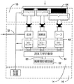
図7は、例示的な小型化された携帯型サイトメーターの斜視図である。このサイトメーターのあるバージョンは、本発明と連携して使用することができる。サイトメーターは、一般に10で示されており、筐体12および取り外し可能もしくは交換可能カートリッジ14を備えることができる。例示的な筐体12は、底部16、カバー18、および底部16をカバー18に取り付ける蝶番20を備えることができる。底部16は、光源22aおよび22b、関連する光学系、およびサイトメーターの動作に必要な電子回路を備えることができる。カバー12は、手動式加圧要素、制御用マイクロ弁を備える圧力室、および関連する光学系を備える光検出器24aおよび24bを備えることができる。
FIG. 7 is a perspective view of an exemplary miniaturized portable cytometer. Some versions of this cytometer can be used in conjunction with the present invention. The cytometer is generally indicated at 10 and can include a
取り外し可能カートリッジ14は、試料捕集装置口32を介して試料流体を受け入れることができる。キャップ38は、取り外し可能カートリッジ14が使用されていない場合に試料捕集装置口32を保護するために使用することができる。取り外し可能カートリッジ14は、コア形成のため血液希釈、赤血球融解、および流体力学的絞り込みを実行することができる。取り外し可能カートリッジ14は、一部がエッチングされた流路を持つ積層構造を使用することで製造されうる、流体回路により構成することができる。
The
取り外し可能構造またはカートリッジ14は、カバー18が開位置にあるときに筐体内に挿入できる。取り外し可能カートリッジ14は、計測装置の異なる部分の間の位置合わせおよび結合を行いやすくする、位置決めピン28aおよび28bを底部16内に受け入れるための穴26aおよび26bを備えることができる。取り外し可能カートリッジ14は、さらに、透明なフロー流窓30aおよび30bを備えることができ、これらは、光源22aおよび22bと光検出器24aと24bの配列に位置を揃えられている。カバーが閉位置に移動され、システムが加圧されると、カバー18は、それぞれ圧力供給口36a、36b、および36cを介して取り外し可能カートリッジ14内の受圧口34a、34b、34cに制御圧力を加えることができる。
The removable structure or
検査を開始するために、カバー18が持ち上げられ、新しいカートリッジ14が入れられ、底部16上で位置を合わせするようにできる。血液試料が試料捕集装置32内に導入されうる。カバー18は閉じられ、システムが手動加圧されうる。加圧は、手動以外であってもよい。加圧された後、計測装置は、白血球サイトメトリー測定および他の測定を実行することができる。取り外し可能カートリッジ14は、コア形成のため血液希釈、赤血球溶解、および流体力学的絞り込みを実行することができる。光源22aおよび22b、光検出器24aおよび24b、ならびに関連する制御および処理電子回路は、光散乱蛍光信号に基づき白血球の分画および計数を実行することができる。筐体12に蝶番付きの構造を使用する代わりに、スライド式カートリッジスロットまたは他の好適な構造を使用することが考えられる。
To begin the inspection, the
図8は、図7の例示的なサイトメーターの略図である。上述のように、底部16は、光源22aおよび22b、関連する光学系、ならびにサイトメーターの動作に必要な制御および処理電子回路40を備えることができる。底部16は、さらに、サイトメーターに給電するための電池42を備えることもできる。手動式加圧要素44、制御用マイクロ弁を備える圧力室46a、46b、および46c、ならびに関連する光学系を備える光検出器24aおよび24bを備えるカバー18が図に示されている。
FIG. 8 is a schematic diagram of the exemplary cytometer of FIG. As mentioned above, the bottom 16 can include
取り外し可能カートリッジ14は、試料捕集装置口32を介して試料流体を受け入れることができる。カバー18により加圧されると、取り外し可能カートリッジ14は、本発明のデバイスにおいて血液希釈、赤血球溶解、およびコア形成のための流体力学的絞り込みを実行することができる。形成された後、図7のフロー流窓30aおよび30bを通る、フロー流経路50の下側にコアが送られうる。底部にある光源22aおよび22bならびに関連する光学系は、フロー流窓30aおよび30bを介してコア流に光を通し、光をコア流に到達させることができる。検出器24aおよび24b、ならびに関連する光学系は、それぞれ、さらにフロー流窓30aおよび30bを介して、コアから散乱光および非散乱光を受け入れることができる。コントローラまたはプロセッサ40は、検出器24aおよび24bから出力信号を受け取り、コア流内に存在する選択された白血球を分画し、識別し、計数することができる。
The
取り外し可能カートリッジ14は、流体のそれぞれの速度の制御を補助するための流体制御ブロック48を備えることができる。例示的な実施例では、流体制御ブロック48は、さまざまな流体の速度を感知するフローセンサーを備え、それらの速度をコントローラまたはプロセッサ40に報告することができる。次いで、コントローラまたはプロセッサ40は、圧力室46a、46b、および46cに関連付けられているマイクロ弁を調節して、サイトメーターを適切に動作させられる所望の圧力およびしたがって、所望の流体速度を得ることができる。
The
血液および他の生物学的廃棄物は、病気を拡大する可能性があるため、取り外し可能カートリッジ14は、廃棄物貯蔵容器52をフロー流窓30aおよび30bの下流に備えるとよい。廃棄物貯蔵容器52は、取り外し可能カートリッジ14内のフロー流の流体を受け入れ、貯蔵することができる。試験が完了したら、取り外し可能カートリッジを取り外して、生物学的廃棄物と親和性のある容器内に処分することができる。
Because blood and other biological waste can spread disease, the
図9は、カバー18がまだ押し下げられていない図8のサイトメーターを示すより詳細な略図である。図10は、カバーが押し下げられている図8のサイトメーターを示すより詳細な略図である。手動式加圧要素44、圧力室46a、46b、および46c、および全体として60で示されている制御用マイクロ弁を備えるカバー18が示されている。光源および検出器は、これらの図に示されていない。
FIG. 9 is a more detailed schematic diagram showing the cytometer of FIG. 8 with the
加圧される流体毎に1つずつ、3つの圧力室46a、46b、および46cがありうる。例示的な実施例において、圧力室46aは、血液試料貯蔵容器62に圧力を加えることができる。圧力室46bは、溶解液貯蔵容器64に圧力を加え、圧力室46cは、シース貯蔵容器66に圧力を加えることができる。それぞれの圧力室46a、46b、および46cのサイズおよび形状は、所望の圧力特性を対応する流体に与えるように手直しすることができる。
There can be three
圧力室46aは、第1の圧力室70および第2の圧力室72を含むことができる。第1の弁74が、第1の圧力室70と第2の圧力室72との間に備えられ、これにより、第1の圧力室70内の圧力を第2の圧力室72へ制御しつつ逃すことができる。第2の圧力室72と流体で連絡している、第2の弁76は、第2の圧力室72内の圧力を制御しつつ抜くことができる。それぞれの弁は、アドレッシングおよび制御を個別に行うことが可能な静電駆動式マイクロ弁の配列とすることができる。圧力室46bおよび46cは、溶解液貯蔵容器64およびシース貯蔵容器66にそれぞれ加えられる圧力を制御する類似の弁を備えることができる。それとは別に、それぞれの弁は、「実効」流量または漏出量が制御しつつ得られる制御可能なデューティサイクルでパルス変調される静電駆動式マイクロ弁の配列とすることができる。
The
取り外し可能カートリッジ14は、カバー18から制御を圧力を受けるための受圧口34a、34b、および34cを備えることができる。制御圧力は、図に示されているように、血液貯蔵容器62、溶解液貯蔵容器64、およびシース貯蔵容器66に供給されうる。溶解液貯蔵容器64およびシース貯蔵容器66は、取り外し可能カートリッジ14が使用のため出荷される前に充填されうるが、血液貯蔵容器62は、試料捕集装置口32から充填される。血液試料は、試料捕集装置口32に供給され、血液試料は、毛管現象により、血液貯蔵容器62内に吸い込まれうる。血液試料が血液貯蔵容器62内に入った後、カバー18を閉じて、システムを加圧することができる。
The
フローセンサーは、流体力学的絞り込みの前にそれぞれの流体と一致するように備えることができる。それぞれのフローセンサー80、100、および102は、対応する流体の速度を測定することができる。フローセンサーは、熱式流速計型フローセンサー、またはマイクロブリッジ型フローセンサーとしてよい。それぞれのフローセンサー80、100、および102からの出力信号は、コントローラまたはプロセッサ40に供給されうる。コントローラまたはプロセッサ40は、血液試料の速度が第1の所定の値よりも低くなった場合に第1の弁74を開き、血液試料の速度が第2の所定の値よりも高くなった場合に第2の弁76を開くことができる。弁84、86、94、および96は、同様の方法で溶解液およびシース液の速度を制御するように動作しうる。
Flow sensors can be provided to match each fluid prior to hydrodynamic constriction. Each
動作中、システムを加圧するために、手動式加圧要素44が押し下げられうる。圧力要素は、非手動機構と置き換えられうる。示されている実施例では、手動式加圧要素44は、3つのプランジャを備え、それぞれのプランジャは第1の複数の圧力室のうちの対応する1つの圧力室内に受け入れられうる。プランジャは、第1の圧力室内に比較的高い非精密圧力を発生することができる。第1の弁74、84、および94を開くことにより、二次室内に、低い制御圧力が発生し、二次室内に制御可能な漏れを生じうる。二次圧力室内に生じる圧力が大きすぎる場合、対応するベント弁76、86、および96が開いて、圧力を逃すようにできる。
In operation, the manual pressurizing
カバー18を閉じたときに、ベント弁76、86、および96を開いているままにして、ノーマルオープンの第1の弁74、84、および94は、閉じることができる。所定の圧力Pが第1の圧力室内に生じたときに、ベント弁76、86、および96を閉じ、第1の弁74、84、および94を開き、二次圧力室に低い圧力P’を生じさせることができる。二次圧力室の制御圧力は、取り外し可能カートリッジ14の流体回路に必要な圧力を供給し、血液、溶解液、およびシースに対する流体流を生じさせることができる。次いで、下流のフローセンサー80、100、および102により、流体流の速度が測定されうる。それぞれのフローセンサーは、対応する第1の弁および弁と弁の動作を制御し、それぞれの流体について所望の流量を一定にするためにコントローラまたはプロセッサ40により使用される出力信号を供給することができる。
When the
全体として110で示されている下流の弁も備えることができる。コントローラまたはプロセッサ40は、システムが加圧されるまで下流弁110を閉じておくことができる。これにより、回路が加圧される前に血液、溶解液、およびシースが流体回路内に流れ込むのを防ぐことができる。本発明の他の例示低名実施例では、下流弁110は、カバーが閉じられたときに機械の作用により開くことができる。
A downstream valve, indicated generally at 110, may also be provided. The controller or
図11は、図9の流体力学的絞り込みブロック88によるフロー流およびコアの形成を示す略図である。流体力学的絞り込みブロック88は、流体駆動装置から制御された速度で血液、溶解液、およびシースを受け取ることができる。血液を溶解液と混合することで、赤血球を取り除くことができる。溶解溶液のpHは、赤血球に比べて低い場合がある。これは、赤血球溶解またはオンザフライ溶解と呼ばれることも多い。残っている白血球は、フロー流50を発生するためにシース液により囲まれている、中心内腔150の下に供給されうる。フロー流50は、シース液152により囲まれているコア流160を含むことができる。流路の寸法は、白血球154および156が一列縦隊で並ぶように、図に示されているとおりに縮小されうる。シース液の速度は、コア流160の約9倍としてよい。しかし、シース液およびコア流160の速度は、流路内に層流を維持できるよう十分遅いものとしてよい。
FIG. 11 is a schematic diagram illustrating flow flow and core formation by the hydrodynamic constriction block 88 of FIG. The hydrodynamic constriction block 88 can receive blood, lysate and sheath at a controlled rate from the fluid drive. Red blood cells can be removed by mixing blood with lysate. The pH of the lysis solution may be lower than that of red blood cells. This is often referred to as red blood cell lysis or on-the-fly lysis. The remaining white blood cells can be supplied under the
発光体22aおよび22bならびに関連する光学系は、フロー流50の片側に隣接して備えることができる。フロー流50を介して発光体22aから光を、また蛍光発光粒子から光を受け取るために、フロー流50の他方の側に光検出器24aおよび24bならびに関連する光学系を備えることができる。光検出器24aおよび24bからの出力信号は、コントローラまたはプロセッサ40に供給され、そこで、コア流160内の選択された白血球を同定し、および/または計数するために分析される。
The
図12は、図11の散乱を介してコア流160の分析用の光源の配列22aおよび光検出器の配列24bを示す略図である。光源は「+」記号として表され、検出器はボックスで表される。示されている実施例では、光源の配列は、フロー流50の片側に隣接して備えられ、光検出器の配列は、フロー流の対向側に隣接して備えられうる。光検出器はそれぞれ、複数の光源のうちの対応する1つの光源に位置を揃えることができる。光源の配列および光検出器の配列は、フロー流50の軸202に関して少し回転された光源軸200にそって整列されるように示されている。
FIG. 12 is a schematic diagram showing an
光源の配列22aは、共通基板上に加工された垂直キャビティ面発光レーザー(VCSEL)などのレーザーの配列であるとしてよい。VCSELは、垂直発光であるため、小型化された携帯型サイトメーターなどのコンパクトな計測装置のパッケージングに適している場合がある。このようなサイトメーターは、ヒトが身につけることができるものとしてよい。VCSELは、従来の850nmよりも短い波長で動作する、または特に、670nmから780nmまでの範囲の波長で動作する「赤色」VCSELとしてよい。赤色VCSELは、散乱測定に適している波長、電力、および偏波特性を有することができる。
The
いくつかのサイトメーターベンチモデルでは、波長650nmの単一9mW端面放射型レーザーを使用することができる。ビームを10×100ミクロンの細長い形状に集束させ、コア流の位置ずれと幅のせいで生じる粒子位置の不確定性に対応することができる。対照的に、本発明の670nmで動作する赤色VCSELの出力は、典型的には、10×10ミクロンの放射体と100ミクロンの間隔に対し約1mWとしてよい。したがって、10個の赤色VCSELの直線配列からの光の全強度は、いくつかの従来技術のベンチモデルと本質的には同じであってよい。 In some cytometer bench models, a single 9 mW edge emitting laser with a wavelength of 650 nm can be used. The beam can be focused into a 10 × 100 micron elongated shape to accommodate particle position uncertainty due to core flow misalignment and width. In contrast, the power of a red VCSEL operating at 670 nm of the present invention may typically be about 1 mW for a 10 × 10 micron emitter and a 100 micron spacing. Thus, the total light intensity from a linear array of 10 red VCSELs may be essentially the same as some prior art bench models.
流れの軸202に関してある角度で向き付けられているレーザーの直線配列することには、単一光源構成に勝る重要な利点が多数ありえる。例えば、レーザーの直線配列は、コア流内の粒子の経路の横方向アライメントを決定するために使用することができる。粒子流のアライメントの不確定性の発生源の1つは、コア流の幅であるとしてよく、これにより、粒子経路位置に統計変動が生じうる。これらの変動は検出器データの分析から判別され、コントローラまたはプロセッサ40はこの変動を利用して、流体駆動装置の弁を調節し、試料流体および支持流体に加えられる相対圧力を変更し、フロー流内の選択された粒子のアライメントを変更することができる。
The linear alignment of lasers oriented at an angle with respect to the
流体流50内の細胞の横方向アライメントを決定するために、VCSELの直線配列により生成される複数の焦点スポットに細胞を通すことができる。細胞は、対応するインライン基準検出器内の信号の低下を引き起こしうる。これらの信号の相対的強弱度は、粒子経路の中心および粒子幅の大きさを決定するためにコントローラまたはプロセッサ40により使用されうる。
To determine the lateral alignment of the cells in the
粒子経路および粒子サイズを決定するために、コア流の平面内で一連のガウススポット214(約1000W/cm2の強度)にレーザー22aが集束されうる。スポット214は、白血球とほぼ同じサイズとしてよい(10〜12μm)。例示的なガウススポット214が、図13に例示されている。検出器の配列24aとのその集束光学系の配列は、流体流50の対向側に備えることができる。かなり大きなFナンバーを有するレンズを使用することで、取り外し可能カートリッジのサイトメーターセクション用の数百ミクロンの作業空間を確保できる。
To determine the particle path and particle size, the
単一レーザー構成ではなくレーザーの直線配列22aを使用する場合の他の利点は、それぞれの細胞の速度を決定できるという点である。粒子速度は、光散乱信号から粒子サイズを推定する際の重要パラメータとすることができる。ある種のサイトメトリーでは、粒子速度は、ポンプ流量から外挿されうる。このアプローチの限界は、ポンプは非常に高精度なものであるべきである、サイトメーターフロー室の公差は厳格に制御されるべきである、漏れなどの流体障害は発生すべきでない、フローまたはコア形成を阻害する微泡などの障害物が入り込むべきではないという条件である。
Another advantage of using a
それぞれの細胞の速度を決定するために、システムは、2つの隣接する、または連続的なスポットの間をそれぞれの細胞が通過するのに要する時間を測定することができる。例えば、図12を参照すると、細胞は、検出器208を通過し、次いで、検出器210を通過することができる。細胞が検出器208から検出器210へ移動するのに要する時間を測定することにより、また検出器208から検出器210までの距離を知ることにより、コントローラまたはプロセッサ40は、細胞の速度を計算することができる。これは、近似的な速度測定結果となるであろう。これは、飛行時間型測定と呼ばれることが多い。速度が判明した後、粒子が中心位置に来るスポットを通って移動する時間(数マイクロ秒)は、粒子の長さおよびサイズの尺度となりうる。
To determine the velocity of each cell, the system can measure the time it takes for each cell to pass between two adjacent or successive spots. For example, referring to FIG. 12, cells can pass through
粒子速度は、さらに、流体駆動装置の制御を補助するために使用できるとも考えられる。本発明のサイズ、コスト、および複雑度を低減するために、図7の交換式カートリッジは、プラスチック積層または成形部品から製造することができる。このような製造技術により安価な部品が得られるが、典型的には、寸法が非対称で、断面の公差が大きく、寸法的正確さおよび反復性があまりよくない。このように公差が大きいほど、特にカートリッジからカートリッジまでの間の粒子速度に、変動を生じる可能性がある。このように大きな公差を補償しやすくするために、コントローラまたはプロセッサ40では本明細書で説明されている飛行時間型測定を使用し、血液、溶解液、およびシース液に加えられる制御圧力を調節し、コア流内の粒子の速度が比較的一定するようにできる。
It is also contemplated that the particle velocity can be used to help control the fluid drive. To reduce the size, cost, and complexity of the present invention, the replaceable cartridge of FIG. 7 can be manufactured from a plastic laminate or molded part. Such manufacturing techniques result in inexpensive parts, but typically are dimensionally asymmetric, have large cross-sectional tolerances, and have poor dimensional accuracy and repeatability. Thus, the greater the tolerance, the more likely it is that the particle velocity between cartridges will vary. To help compensate for such large tolerances, the controller or
さらに、細胞サイズを評価するために、細胞経路にそって、さらに細胞経路を横切る形で、レーザー・ビームを集束させることができると考えられる。さらに、細胞を横切る複数のサンプルをテクスチャ特徴に関して分析し、形態学的特徴と他の細胞種類との相関を求めることができる。これにより細胞サイズに関する複数のパラメータが得られ、細胞種類を互いに分離させるのに役立ちうる。 Furthermore, it is believed that the laser beam can be focused along the cell path and further across the cell path to assess cell size. In addition, multiple samples across cells can be analyzed for texture features to determine correlations between morphological features and other cell types. This provides a plurality of parameters related to cell size, which can help to separate cell types from each other.
単一レーザー源構成ではなくレーザーの直線配列22aを使用する場合の他の利点は、流路を横切る形で比較的一定した光照射を与えることができるという点である。これは、図13に示されているように、隣接するVCSEL 22aからのガウスビーム214を重ね合わせることにより達成されうる。単一レーザーシステムでは、流路を横切る光照射は、その流路を横切るときに変化しうる。そのため、粒子が、流路の中心にない場合、その後の測定の精度は落ちる可能性がある。
Another advantage of using a
上述の測定を実行するために、図12のそれぞれの検出器24aは、単一のインライン検出器とすることができる。しかし、FALSおよびSALSの散乱を測定するために、それぞれの検出器24aは、さらに、図14に示されているように、インライン検出器の周りに配置された2つの環状検出器を備えることができる。この図を参照すると、VCSEL 218は、光を上向き方向に送るように示されている。光はレンズに通され、レンズはコア流の平面内のガウススポットに光を集束させることができる。レンズ220は、マイクロレンズなどであってよく、VCSEL 218と別であるか、または一体化されている。光はコア流を通過し、回折光学素子などの他のレンズ222により受け取られる。レンズ222は、光をインライン検出器226および環状検出器228および230に送ることができる。インライン検出器226は、コア流内で粒子により著しく散乱されない光を検出することができる。環状検出器228は、前方散乱(FALS)光を検出することができ、環状検出器230は、小角度散乱(SALS)光を検出することができる。
To perform the measurements described above, each
図15は、光源および光検出器の3つの別々の配列を備えることができる例示的な他の実施例を示している。光源および光検出器のそれぞれの配列は、フロー流の中心流軸に関して少し回転された異なる光源軸にそって位置決めされうる。3つの配列を使用することにより、それぞれの配列に関連付けられている光学系は、特定の用途または機能に合わせて最適化されうる。小画散乱(SALS)を検出するためには、コア流の平面上に十分に集束されているレーザー光が望ましい。前方散乱(FALS)を検出するためには、コリメート光が望ましい。 FIG. 15 illustrates another exemplary embodiment that can comprise three separate arrays of light sources and photodetectors. Each array of light sources and photodetectors can be positioned along different light source axes that are slightly rotated with respect to the central flow axis of the flow stream. By using three arrays, the optics associated with each array can be optimized for a particular application or function. In order to detect small image scattering (SALS), laser light that is well focused on the plane of the core flow is desirable. Collimated light is desirable for detecting forward scattering (FALS).
図15を参照すると、光源および光検出器の第1の配列が、300で示されている。光源および光検出器は、第1の光源軸にそって直線配列として配置されうる。第1の光源軸は、フロー流の流れ軸に関して回転されうる。光源および光検出器は、図12に関して上で説明されているものと類似のものであってよいが、例えば、フロー流内の細胞の横方向アライメント、粒子サイズ、粒子の速度を測定するために使用されうる。 Referring to FIG. 15, a first arrangement of light sources and photodetectors is indicated at 300. The light sources and photodetectors can be arranged as a linear array along the first light source axis. The first light source axis may be rotated with respect to the flow axis of the flow stream. The light source and photodetector may be similar to that described above with respect to FIG. 12, but for example to measure the lateral alignment of cells in the flow stream, particle size, particle velocity Can be used.
上で示されているように、ユーザーは、取り外し可能カートリッジを取得し、血液試料を取り外し可能カートリッジの試料捕集装置口32(図7を参照)に送ることができる。血液試料は、例えば、指に針を刺すことで集めることができる。ユーザーは、次いで、取り外し可能カートリッジを筐体内に挿入し、手動でシステムを加圧することができる。次いで、小型化された携帯型サイトメーターは、ユーザーが医療を求めるべきかどうかを示す読み取り値を与えることができる。この読み取り値は、視覚的読み取り値、可聴音、または他の好適なインジケータとすることができる。 As indicated above, the user can obtain a removable cartridge and send a blood sample to the sample collector port 32 (see FIG. 7) of the removable cartridge. The blood sample can be collected, for example, by inserting a needle into a finger. The user can then insert the removable cartridge into the housing and manually pressurize the system. The miniaturized portable cytometer can then provide a reading that indicates whether the user should seek medical care. This reading may be a visual reading, audible sound, or other suitable indicator.
指を針で刺すなどの方法で血液試料を取得する代わりに、カテーテル804(図27)などをユーザーの静脈に挿入し、試料捕集装置口32に取り付けることができる。これにより、システムは、読み取り値が必要な場合に血液試料をユーザーから自動的に捕集することができる。それとは別に、小型化された携帯型サイトメーターは、試料捕集装置口32が好適な血液供給源に接続された状態でユーザー体内に埋め込むことができると考えられる。
Instead of acquiring a blood sample by a method such as pricking a finger with a needle, a catheter 804 (FIG. 27) or the like can be inserted into the user's vein and attached to the
図16は、例示的な取り外し可能カートリッジのいくつかの特徴の略図である。例示的な取り外し可能カートリッジは、一般的に400で示されており、本明細書で説明されている取り外し可能カートリッジ14に類似のものとしてよい。取り外し可能カートリッジ400は、例示されているにすぎず、本発明の実施例は、形態、機能、または構成に関係なく、多くのマイクロ流体カートリッジに適用されうることは理解されるであろう。例えば、本発明の実施例は、フローサイトメトリー、血液検査、免疫アッセイ、臨床化学、血液化学分析、尿検査、血液ガス分析、ウイルス分析、バクテリア分析、電解質測定などに適合された取り外し可能カートリッジに応用可能である。また、取り外し可能カートリッジ400などの本発明の取り外し可能カートリッジは、例えば、ガラス、シリコン、1つまたは複数のポリマーを含む好適な材料もしくは材料系、または他の好適な材料もしくは材料系、または材料もしくは材料系の組み合わせから作ることができることも考えられる。
FIG. 16 is a schematic illustration of some features of an exemplary removable cartridge. An exemplary removable cartridge is generally indicated at 400 and may be similar to the
例示的な取り外し可能カートリッジ400は、第1の測定流路402および第2の測定流路404を備えるが、必要に応じて使用する測定流路を加減することも可能である。例示的な実施例における第1の測定流路402は、赤血球測定流路であり、第2の測定流路404は、白血球測定流路である。全血試料は、血液受口406を介して取り外し可能カートリッジ402より受け取られ、毛管作用により、知られている量の血液が抗凝血剤コーティング血液試料貯蔵毛細管408内に引き込まれる。試料押し(P)圧力が、試料押し流体貯蔵容器に加えられる。圧力が加えられると、試料押し流体が強制的に、試料押し流体貯蔵容器から血液試料押し流路410内に送り込まれる。
The exemplary
例示的ないくつかの実施例では、弁412およびフローセンサー414を血液試料押し流路410と一列になるように備えることができる。弁412は、血液試料を流体回路に押し通すことが望ましい場合に、開くように制御できる。フローセンサー414は、血液試料押し流体の流量を測定することができ、したがって、抗凝血剤コーティング毛細管408を通る血液試料流量を測定することができる。フローセンサー414から得られる流量は、取り外し可能カートリッジ400に供給される試料押し(P)圧力を制御しやすくするために使用されうる。
In some illustrative examples, a
例示的な実施例では、全血試料は分割され、ブランチ416を介して赤血球測定流路402および白血球測定流路404に送られる。例示的な実施例では、弁418は、赤血球測定流路402内に入る血液試料流を制御するためにブランチと一列になるように備えられ、弁420は、白血球測定流路404内に入る血液試料流を制御するように備えられる。
In the exemplary embodiment, the whole blood sample is divided and sent to red blood
赤血球測定流路402を特に参照すると、赤血球球状化試薬圧力(SP)が球状化試薬貯蔵容器に加えられることがわかる。圧力が加えられると、球状化試薬貯蔵容器内の球状化試薬が強制的に、球状化試薬流路424内に送られる。
With particular reference to the
例示的ないくつかの実施例では、弁426およびフローセンサー428は、さらに、球状化試薬流路424と一列になるように備えることができる。弁426は、球状化試薬を流体回路に押し込むことが望ましい場合に、開くように制御できる。フローセンサー428は、球状化試薬の流量を測定することができ、球状化試薬流路424を通る球状化試薬の流量を測定することができる。フローセンサー428から得られる流量は、圧力源/コントローラにより取り外し可能カートリッジ400に供給される赤血球球状化試薬圧力(SP)を制御しやすくするために使用されうる。
In some illustrative examples, the
例示的な取り外し可能カートリッジ400の通常の機能動作中に、形状化試薬が球状化試薬流量の交差領域430内に押し込まれ、血液試料が血液試料流量の交差領域430に押し込まれる。血液試料流量および球状化試薬流量は、圧力源/コントローラにより制御されうる。
During normal functional operation of the exemplary
交差領域430は、球状化試薬が血液試料の周囲を流れる動作が、両方の流体が交差領域430内を流れるときに生じるように構成されうる。場合によっては、球状化試薬流量は、血液試料流量より高くてもよく、これにより下流のオンザフライ球状化流路432内の流量特性を改善し、場合によっては、球状化試薬により完全に、また一様に囲まれている薄いリボン状の血液を形成しやすくすることができる。このようなリボン状の流れは、オンザフライ球状化流路432内を移動するときに球状化試薬が赤血球を一様に球状化するのを助けることができる。さらに、オンザフライ球状化流路432の長さは、球状化試薬および血液試料の流量と併せて、血液試料が適切な時間の間に球状化試薬に曝されるように設定できる。
The
シース液(SH)圧力をシース液貯蔵容器に加えることができる。圧力が加えられると、シース液が強制的に、シース液貯蔵容器からシース流路434内に送り込まれる。例示的ないくつかの実施例では、弁436およびフローセンサー438をシース流路434と一列になるように備えることができる。弁436は、シース液を流体回路に押し込むことが望ましい場合に、開くように制御できる。フローセンサー438は、シース液の流量を測定することができ、シース流路434を通るシース流量を測定することができる。フローセンサー438から得られる流量は、取り外し可能カートリッジ400に供給されるシース圧力(SH)を制御しやすくするために使用されうる。
Sheath fluid (SH) pressure can be applied to the sheath fluid reservoir. When pressure is applied, the sheath liquid is forcibly sent from the sheath liquid storage container into the
例示されている実施例では、シース液は、シース液流量の交差領域440に供給され、球状化された血液試料は、球状化された血液試料の流量の交差領域440に供給される。球状化された血液試料の流量およびシース流量は、圧力源/コントローラにより制御されうる。
In the illustrated embodiment, sheath fluid is supplied to the crossed
交差領域440は、シース液が球状化された血液試料の周囲を流れる動作が、両方の流体が交差領域440内を流れるときに生じるように構成されうる。いくつかの場合において、シース流量は、球状化された血液試料の流量に比べて著しく高く、下流のフローサイトメトリー流路442内のコア形成を改善するのに役立ちうる。例えば、いくつかのフローサイトメトリー用途では、この交差領域440は、それぞれの赤血球を取り外し可能カートリッジ400内の光学的窓領域444を通過するときに分析器により個別に光学的に問い合わせできるように一列縦隊のコア内に球状化された血液細胞を流体力学的に集束させ、配列するように構成されうる。いくつかの場合において、サイトメトリー流路442を通過する流体は、オンボード廃棄物貯蔵容器に向けられる。
The
次に、白血球測定流路404を参照すると、白血球溶血剤圧力(L)が溶血剤貯蔵容器に加えられうることがわかる。圧力が加えられると、溶解液貯蔵容器内の溶血剤が強制的に、溶血剤流路454内に送られる。
Next, referring to the white blood cell measurement channel 404, it can be seen that the white blood cell hemolytic agent pressure (L) can be applied to the hemolytic agent storage container. When pressure is applied, the hemolytic agent in the lysate storage container is forcibly sent into the
例示的ないくつかの実施例では、弁456およびフローセンサー458は、さらに、溶血剤流路454と一列になるように備えることができる。弁456は、溶血剤を流体回路に押し込むことが望ましい場合に、開くように制御できる。フローセンサー458は、溶血剤の流量を測定することができ、溶血剤流路454を通る溶血剤の流量を測定することができる。フローセンサー458から得られる流量は、圧力源/コントローラにより取り外し可能カートリッジ400に供給される白血球溶血剤圧力(L)を制御しやすくするために使用されうる。
In some illustrative examples, the
例示的な取り外し可能カートリッジ400の通常の機能動作中に、溶血剤が溶血剤流量の交差領域460内に供給され、血液試料が血液試料流量の交差領域460に供給される。血液試料流量および溶血剤流量は、圧力源/コントローラにより制御されうる。
During normal functional operation of the exemplary
交差領域460は、溶血剤が血液試料の周囲を流れる動作が、両方の流体が交差領域460内を流れるときに生じるように構成されうる。場合によっては、溶血剤流量は、血液試料流量より高くてもよく、これによりオンザフライ溶解流路462内の流量特性を改善し、場合によっては、溶血剤により完全に、また一様に囲まれている薄いリボン状の血液を形成しやすくすることができる。このようなリボン状の流れは、オンザフライ溶解流路462内を移動するときに溶血剤が赤血球を一様に溶解するのを助けることができる。さらに、オンザフライ溶解流路462の長さは、溶血剤および血液試料の流量と併せて、血液試料が適切な時間の間に溶血剤に曝されるように設定できる。
シース液(SH)圧力をシース液貯蔵容器に加えることができる。圧力が加えられると、シース液が強制的に、シース液貯蔵容器からシース流路464内に送り込まれる。例示的ないくつかの実施例では、弁466およびフローセンサー468をシース流路464と一列になるように備えることができる。弁466は、シース液を流体回路に押し込むことが望ましい場合に、開くように制御できる。フローセンサー468は、シース液の流量を測定することができ、シース流路464を通るシース流量を測定することができる。フローセンサー468から得られる流量は、取り外し可能カートリッジ400に供給されるシース圧力(SH)を制御しやすくするために使用されうる。いくつかの場合において、シース流路464を通るシース流量は、シース流路434を通るシース流量と同じである。しかし、他の場合には、シース流路464を通るシース流量は、シース流路434を通るシース流量と異なる場合もある。
Sheath fluid (SH) pressure can be applied to the sheath fluid reservoir. When pressure is applied, the sheath liquid is forcibly sent from the sheath liquid storage container into the
例示されている実施例では、シース液は、シース液流量の交差領域470に供給され、溶解された血液試料は、溶解された血液試料の流量の交差領域470に供給される。溶解された血液試料の流量およびシース流量は、圧力源/コントローラにより制御されうる。
In the illustrated embodiment, sheath fluid is supplied to the
交差領域470は、シース液が溶解された血液試料の周囲を流れる動作が、両方の流体が交差領域470内を流れるときに生じるように構成されうる。いくつかの場合において、シース流量は、溶解された血液試料の流量に比べて著しく高く、下流のフローサイトメトリー流路472内のコア形成を改善するのに役立ちうる。例えば、いくつかのフローサイトメトリー用途では、この交差領域470は、それぞれの白血球を取り外し可能カートリッジ400内の光学的窓領域474を通過するときに分析器により個別に光学的に問い合わせできるように一列縦隊のコア内に溶解された血液試料を流体力学的に集束させ、配列するように構成されうる。いくつかの場合において、サイトメトリー流路472を通過する流体は、オンボード廃棄物貯蔵容器に供給される。
いくつかの場合において、吸収測定流路も備えることができる。例示的な実施例では、溶解された血液試料の一部が吸収流路480に送られる。弁482は、溶解された血液試料の一部を選択的に、吸収領域484に移動できるように備えることができる。分析器は、吸収領域484を照らすための光源だけでなく、吸収領域484内の溶解された血液試料により吸収されない光を検出するための検出器をも備えることができる。次いで、分析器は、バルク吸収ベースのヘモグロビン測定を行える吸収レベルを決定することができる。いくつかの場合において、吸収流路480は、必要ならば、サイトメトリー流路472の下流に配置されうる。他の場合には、全血試料は、ブランチ416などから吸収流路へ、直接供給されうる。そのような場合、吸収流路は、吸収測定を実行するのに先立って赤血球を溶解するための機構を備えることができる。例示的な取り外し可能カートリッジ400は、全血試料に対し完全血球算定(CBC)分析を実行するように適合されているが、他の取り外し可能カートリッジ構成および分析タイプも、必要に応じて使用できることが考えられる。
In some cases, an absorption measurement channel can also be provided. In the exemplary embodiment, a portion of the lysed blood sample is sent to
RBC/P測定流路604内で、赤血球は、612に示されているように最初に球状化され、次いで、流体力学的に集束され、取り外し可能カートリッジ内のRBC/Pサイトメトリー流路614の下に一列縦隊で送られる。垂直キャビティ面発光レーザー(VCSEL)などの光源616は、個々の細胞がRBC/Pサイトメトリー流路614の分析領域を通り過ぎるときにそれらの細胞に光を当てる。いくつかの場合において、VCSELデバイスの配列が備えられ、個々の細胞がRBC/Pサイトメトリー流路614の分析領域を通り過ぎるときにそれらの細胞と揃えられる(複数の)VCSELのみが活性化される。VCSELにより送られる入射光の一部が散乱され、検出器618は、その散乱された光を検出する。いくつかの場合において、検出器618は、前方角度散乱光(FALS)、小角度散乱光(SALS)、および大角度散乱光(LALS)を検出することができる。
Within the RBC /
いくつかの場合において、レーザー(または他の)光源は、細長い線光源として、または2つの別々のスポット光源として、RBC/Pサイトメーター流路614内に集束される。RBCおよびRBC/Pサイトメーター流路614内の血小板は、集束光に通される。高品質集光光学系を使用することで、細胞の鮮明な像および集光を、縦軸がRBC/Pサイトメーター流路614内の流れの方向に直交するように配置された1つ、2つ、またはそれ以上の平行なスリットを含む不透明スクリーン上に形成することができる。これらのスリット間の距離は、例えば、RBC/Pサイトメーター流路614内で予想される平均細胞分離距離の程度としてよい。これらのスリットを含む不透明スクリーンは、1つまたは複数の検出器618の前に置くことができる。細胞の像が1つのスリットを通り越すときに、これはスリット上に入射する光を遮り、検出器618上の信号を弱め、幅が細胞直径に比例するパルス波形を発生する。2つの相隔てて並ぶスリットが備えられた場合、2つの波形は、細胞流速の計算を許すものとなりうる。この技術を使用することで、高信号対雑音比が得られ、これにより、イベントの計数と、複数の細胞イベントの同定が容易に行える。さらに、パルスの幅と振幅で、いくつかの細胞タイプの弁別が可能になる場合がある。
In some cases, the laser (or other) light source is focused into the RBC /
いくつかの場合において、細胞と光源の両方の像が、検出器618の前に置かれた二重スリット開口上に結像される。この二重スリット開口は、明確に定められた幾何学的開口をなし、細胞を計数するための高い信号対雑音比をもたらす。上述のように、これらのスリットからの信号は、細胞流速の正確な測定を可能にし、次いで、細胞直径の計算も可能にしうる。 In some cases, both cell and light source images are imaged onto a double slit aperture placed in front of detector 618. This double slit aperture makes a well-defined geometric aperture and provides a high signal-to-noise ratio for counting cells. As mentioned above, the signals from these slits may allow accurate measurement of cell flow rates and then cell diameter calculations.
いくつかの場合において、620に示されているように、この分析の際に、例えば、試料流量(FR)、測定時間(T)の長さ、および試料希釈係数(DF)を含む、多数のパラメータを測定することができる。(複数の)検出器の出力、および/または対応する散乱シグネチャを監視することにより、赤血球数(NRB)、血小板数(NPlt)、それぞれの細胞の直径(drbc)を測定することができる。 In some cases, as shown at 620, during this analysis, a number of samples including, for example, sample flow rate (FR), length of measurement time (T), and sample dilution factor (DF) are included. Parameters can be measured. By monitoring the output of the detector (s) and / or the corresponding scatter signature, the red blood cell count (N RB ), platelet count (N Plt ), and the diameter of each cell (drbc) can be measured. .
これらのパラメータから、また682に示されているように、例えば、赤血球数(RBC=NRB/(DF×FR×T))、血小板数(Plt=NPlt/(DF×FR×T))、平均細胞ヘモグロビン濃度(MCHC=<CHC>)、平均細胞体積(MCV=(π/6)×<drbc3>)、平均細胞ヘモグロビン含有量(MCH=(π/6)×<drbc3×CHC>)、相対分布幅(RDW=[(π/6)×drbc3]/MCVの標準偏差)、ヘマトクリットパラメータ(Hct=RBC×MCV)、および/またはヘモグロビン濃度(Hb=MCHC×Hct)を含む、多数の赤血球分析パラメータが計算されうる。 From these parameters and as shown in 682, for example, red blood cell count (RBC = N RB / (DF × FR × T)), platelet count (Plt = N Plt / (DF × FR × T)) Mean cell hemoglobin concentration (MCHC = <CHC>), mean cell volume (MCV = (π / 6) × <drbc 3 >), mean cell hemoglobin content (MCH = (π / 6) × <drbc 3 × CHC) >), Relative distribution width (RDW = [(π / 6) × drbc 3 ] / MCV standard deviation), hematocrit parameter (Hct = RBC × MCV), and / or hemoglobin concentration (Hb = MCHC × Hct) A number of red blood cell analysis parameters can be calculated.
例示的なWBC測定流路606内で、赤血球は、632に示されているように最初に溶解され、次いで、流体力学的に集束され、取り外し可能カートリッジ内のWBCサイトメトリー流路634の下に一列縦隊で送られる。垂直キャビティ面発光レーザー(VCSEL)などの光源636は、個々の細胞がWBCサイトメトリー流路634の分析領域を通り過ぎるときにそれらの細胞に光を当てる。いくつかの場合において、VCSELデバイスの配列が備えられ、個々の細胞がWBCサイトメトリー流路634の分析領域を通り過ぎるときにそれらの細胞と揃えられる(複数の)VCSELのみが活性化される。VCSELにより送られる入射光の一部が散乱され、検出器638は、その散乱された光を検出する。いくつかの場合において、検出器638は、前方角度散乱光(FALS)、小角度散乱光(SALS)、および大角度散乱光(LALS)を検出する。いくつかの場合において、640に示されているように、この分析の際に、例えば、軸上細胞体積、全WBC数、およびWBC 5分画を含む、多数のパラメータを測定することができる。
Within the exemplary
図18は、多数の赤血球パラメータを取得するための例示的なアプローチを示す流れ図である。例示的なアプローチでは、ステップ660で血液試料が取得される。次に、血液試料が所望の希釈係数(DF)となるように希釈され、664に示されているように球状化される。次いで、希釈され、球状化された血球は、流体力学的に集束され、取り外し可能カートリッジ内のRBC/Pサイトメトリー流路の下に一列縦隊で送られる。垂直キャビティ面発光レーザー(VCSEL)などの光源616は、個々の細胞がRBC/Pサイトメトリー流路の分析領域を通り過ぎるときにそれらの細胞に光を当てる。(複数の)VCSELにより送られる入射光の一部が散乱され、検出器は、その散乱された光を検出するために使用される。いくつかの場合において、検出器は、それぞれの細胞について前方角度散乱光(FALS)と小角度散乱光(SALS)の両方を検出する。次いで、プロセッサなどが、それぞれの細胞に対する2つの独立の散乱パラメータ、つまり、SALSおよびFALSを、
{SSALSi,SFALSi}→{drbci,CHCi}
のように細胞直径パラメータおよび細胞ヘモグロビン濃度パラメータにマッピングすることができる。
FIG. 18 is a flow diagram illustrating an exemplary approach for obtaining a number of red blood cell parameters. In the exemplary approach, a blood sample is obtained at
{S SALSi , S FALSi } → {drbc i , CHC i }
Can be mapped to the cell diameter parameter and the cell hemoglobin concentration parameter.
670に示されているように、散乱SSALSiプラスSFALSiの強度が所定の検出閾値以下の場合、制御はステップ668に戻される。しかし、散乱SSALSiプラスSFALSiの強度が所定の検出閾値よりも大きい場合、制御はステップ672に渡される。ステップ672で、SSALSiとSFALSiの合計が所定の血小板閾値よりも大きいかどうかを判定する。SSALSiとSFALSiの合計が所定の血小板閾値以下である場合、粒子「i」は血小板であると判定され、制御は、ステップ674に渡される。ステップ674で、計数された血小板の数(NPlt)を1だけ増やし、制御をステップ668に戻す。
As shown at 670, if the intensity of the scattered S SALSi plus S FALSi is less than or equal to a predetermined detection threshold, control is returned to step 668. However, if the intensity of the scattered S SALSi plus S FALSi is greater than a predetermined detection threshold, control is passed to step 672. In
SSALSiとSFALSiの合計が所定の血小板閾値よりも大きい場合、その細胞は赤血球であり、制御は、ステップ676に渡される。ステップ676で、計数された赤血球数(NRBC)を1だけ増やし、制御をステップ678に戻す。ステップ678で、所定の測定時間に達したかどうかを判定する。所定の時間に達していない場合、制御はステップ668に戻される。
If the sum of S SALSi and S FALSi is greater than a predetermined platelet threshold, the cell is a red blood cell and control is passed to step 676. In
ステップ678で、測定時間に達した後、制御はステップ680に渡される。ステップ680で、例えば、試料流量(FR)、測定時間(T)の長さ、試料希釈係数(DF)、計数された赤血球数(NRBC)、計数された血小板数(NPlt)、それぞれの細胞の直径(drbci)、およびそれぞれの細胞のヘモグロビン濃度(CHCi)を含む多数の測定パラメータを示す。これらのパラメータから、またステップ682に示されているように、例えば、赤血球数(RBC=NRBC/(DF×FR×T))、血小板数(Plt=NPlt/(DF×FR×T))、平均細胞ヘモグロビン濃度(MCHC=<CHCi>)、平均細胞体積(MCV=(π/6)×<drbci 3>)、平均細胞ヘモグロビン含有量(MCH=(π/6)×<drbci 3×CHCi>)、相対分布幅(RDW=[(π/6)×drbci 3]/MCVの標準偏差)、ヘマトクリットパラメータ(Hct=RBC×MCV)、および/またはヘモグロビン濃度(Hb=MCHC×Hct)を含む、多数の赤血球分析パラメータが計算されうるが、ただし、表記<Xi>は、すべての細胞Xiにわたる平均細胞パラメータを意味する。
After the measurement time is reached at
図19は、血液試料を分析するための他の例示的なアプローチを示す概略流れ図である。この例示的なアプローチでは、ステップ700で示されているように、血液試料が取得され、血液試料貯蔵容器に送られる。次に、血液試料が、取り外し可能カートリッジ内の抗凝血剤コーティング毛細管に送られ、希釈される。次いで、血液試料は、分割され、赤血球および血小板(RBC/P)測定流路704ならびに白血球(WBC)測定流路740に送られる。
FIG. 19 is a schematic flow diagram illustrating another exemplary approach for analyzing a blood sample. In this exemplary approach, as shown in
RBC/P測定流路704内で、赤血球は、706に示されているように最初に球状化され、次いで、流体力学的に集束され、取り外し可能カートリッジ内のRBC/Pサイトメトリー流路708の下に一列縦隊で送られる。垂直キャビティ面発光レーザー(VCSEL)などの第1の光源710および関連する光学系は、個々の細胞がRBC/Pサイトメトリー流路708の分析領域を通り過ぎるときにそれらの細胞に集光ビームを送る。いくつかの場合において、VCSELデバイスの配列が備えられ、個々の細胞がRBC/Pサイトメトリー流路708の分析領域を通り過ぎるときにそれらの細胞と揃えられる(複数の)VCSELのみが活性化される。
Within the RBC /
個々の細胞/粒子が集束入射光ビームを通過するときに、光の一部がブロックされ、散乱されるか、または他の何らかの方法で遮られるが、検出器により検出されうる(図に示されていない)。2つまたはそれ以上の光源がRBC/Pサイトメトリー流路708にそって相隔てて並ぶ異なるスポット上に集束されると、それぞれの細胞の前縁および/または後縁が検出されうる。細胞が1つの集束スポットから次の集束スポットまでの距離を横断するのに要する時間を測定することにより、流量、したがって細胞速度が決定されうる。細胞速度が決定されると、細胞が光ビームをブロックするか、散乱するか、または他の何らかの方法で遮る時間の長さが、細胞サイズおよび/または細胞体積に相関されうる。
As individual cells / particles pass through the focused incident light beam, some of the light is blocked, scattered, or otherwise blocked, but can be detected by a detector (shown in the figure). Not) When two or more light sources are focused on different spots spaced apart along the RBC /
いくつかの実施例では、分析器に他の光源714および関連する光学系が備えられうる。光源714の関連する光学系は、光を平行にし、SALSおよびFALS散乱などの軸外し散乱を測定することができる。上記のように、SALSおよびFALS散乱は、計数された赤血球数(NRBC)716、計数された血小板数(NPlt)722、それぞれの細胞の直径(drbci)、細胞体積718、およびそれぞれの細胞のヘモグロビン濃度720(CHCi)を測定するために使用されうる。これらのパラメータから、また上述のように、例えば、赤血球数(RBC=NRBC/(DF×FR×T))、血小板数(Plt=NPlt/(DF×FR×T))、平均細胞ヘモグロビン濃度(MCHC=<CHCi>)、平均細胞体積(MCV=(π/6)×<drbci 3>)、平均細胞ヘモグロビン含有量(MCH=(π/6)×<drbci 3×CHCi>)、相対分布幅(RDW=[(π/6)×drbci 3]/MCVの標準偏差)、ヘマトクリットパラメータ(Hct=RBC×MCV)、および/またはヘモグロビン濃度(Hb=MCHC×Hct)を含む、多数の赤血球分析パラメータが計算されうるが、ただし、表記<Xi>は、すべての細胞Xiにわたる平均細胞パラメータを意味する。
In some embodiments, the analyzer can be provided with other
例示的なWBC測定流路740では、赤血球が溶解され、742に示されているように、染料が適宜注入される。次いで、細胞は、流体力学的に集束され、取り外し可能カートリッジ内のWBCサイトメトリー流路744の下に一列縦隊で送られる。垂直キャビティ面発光レーザー(VCSEL)などの光源746は、個々の細胞がWBCサイトメトリー流路744の分析領域を通り過ぎるときにそれらの細胞に光を当てる。いくつかの場合において、VCSELデバイスの配列が備えられ、個々の細胞がWBCサイトメトリー流路744の分析領域を通り過ぎるときにそれらの細胞と揃えられる(複数の)VCSELのみが活性化される。
In the exemplary
個々の細胞/粒子が集束入射光ビームを通過するときに、光の一部がブロックされ、散乱されるか、または他の何らかの方法で遮られるが、検出器により見つけることができる(図に示されていない)。2つまたはそれ以上の光源がWBCサイトメトリー流路744にそって相隔てて並ぶ異なるスポット上に集束されると、それぞれの細胞の前縁および/または後縁が検出されうる。細胞が1つの集束スポットから次の集束スポットまでの距離を横断するのに要する時間を測定することにより、流量、したがって細胞速度が決定されうる。細胞速度が決定されると、細胞が光ビームをブロックするか、散乱するか、または他の何らかの方法で遮る時間の長さが、細胞サイズおよび/または細胞体積に相関されうる。 As individual cells / particles pass through the focused incident light beam, some of the light is blocked, scattered, or otherwise obstructed, but can be found by the detector (shown in the figure). It has not been). When two or more light sources are focused on different spots that are spaced apart along the WBC cytometry channel 744, the leading and / or trailing edges of each cell can be detected. By measuring the time it takes for a cell to traverse the distance from one focused spot to the next, the flow rate, and thus the cell velocity, can be determined. Once the cell velocity is determined, the length of time that the cell blocks, scatters or otherwise blocks the light beam can be correlated to cell size and / or cell volume.
いくつかの実施例では、分析器に他の光源750および関連する光学系および/または偏光器が備えられうる。光源750の関連する光学系は、光を平行にし、754に示されているように、SALS、FALS、およびLALS散乱などの軸外し散乱を測定することができる。上記と同様に、SALS、FALS、およびLALS散乱は、例えば、計数された白血球数(NWBC)752を測定するとともに、756に示されているように、白血球の分画を行いやすくするためにも使用することができる。いくつかの場合において、1つまたは複数の偏光器を備え、これにより、光源から発せられる光を偏光することができ、また検出器で検出された偏光消光/回転のレベルを使用して、白血球の分画を実行しやすくすることができるが、これはすべての実施例において必要というわけではない。 In some embodiments, the analyzer can be provided with other light sources 750 and associated optics and / or polarizers. The associated optics of the light source 750 can collimate the light and measure off-axis scattering, such as SALS, FALS, and LALS scattering, as shown at 754. Similar to the above, SALS, FALS, and LALS scatter, for example, to measure counted white blood cell count (N WBC ) 752 and to facilitate leukocyte fractionation as shown at 756 Can also be used. In some cases, one or more polarizers are provided so that the light emitted from the light source can be polarized and the level of polarization quenching / rotation detected by the detector can be used to However, this is not necessary in all embodiments.
血液試料中のヘモグロビン(Hb)の量またはヘモグロビン濃度を決定するために、別のモジュールが使用可能である。モジュールは、ヘモグロビン吸収を使用してHbを決定することができる。血液中のヘモグロビンの量は、グラム/リットルまたは他の単位の組み合わせで表すことができる。例示的な一実施例では、WBCサイトメトリー流路744を出た細胞を、バルク吸収流路760に送ることができる。光源762は、吸収流路760内に存在する細胞上に光を当て、検出器764は、常在細胞により吸収されない光を検出することができる。そこで、吸収流路760を、常在細胞のバルク吸収レベルを測定するために使用できる。例えば、吸収レベルは、血液試料中のバルクまたは平均細胞ヘモグロビン濃度の尺度となりうる。ヘモグロビン流路は、出力値再ゼロ調整光学系およびオートフォーカスおよび/またはアライメントを備えることができる。光源762は、吸収ピークの中心に近い出力を有するLEDであってよく、したがって場合によってはフィルタが不要になる。ヘモグロビンに関して評価される試料を受け入れ、保持するためのキュベットがあってもよい。
Another module can be used to determine the amount of hemoglobin (Hb) or hemoglobin concentration in the blood sample. The module can determine Hb using hemoglobin absorption. The amount of hemoglobin in the blood can be expressed in grams / liter or other unit combinations. In one exemplary embodiment, cells exiting the WBC cytometry channel 744 can be sent to the
図20は、HGBカード770またはモジュールの一実施例を示している。乾燥溶解粉末の堆積/プリントがある場所を示す溶血剤堆積領域771があってもよい。HGB測定精度を改善するために乾燥溶解粉末により血液溶解時に発生する気泡をなくす気泡トラップ配置を示す領域773内の一番最後のターンにちょっと動かされたコーナー772がありうる。
FIG. 20 shows an embodiment of the
図21は、散乱光学サブシステム501および蛍光光学サブシステム502を示すサイトメーターカートリッジ500を示している。光学サブシステム501は、それぞれの側面流路530上に窓または開口部30aを備え、光学サブシステム502は、窓または開口部30bを備えることができる。それぞれのサブシステムにおいて、流路530のそれぞれの側面に窓または開口部があってよい。これらの開口部は、光学的挿入物またはレンズを備えることができる。このサイトメーターは、人体に身につける、人体に取り付ける、または人体に挿入するように実装されうる。
FIG. 21 shows a
図22は、それぞれ光学サブシステム501および502を組み込むことができるシステム503および504を示している。システム503は、さらに、コア流160内の白血球などの粒子の散乱測定のためVCSEL配列22aおよび検出器配列24aを備えることもできる。このシステムは、リンパ球および好中球の計数および分類に使用されうる。セルフアライメントも、赤色VCSEL配列ベースの光学サブシステムにより使用可能にできる。ここでは散乱システム503の例示的ないくつかの実施について説明する。
FIG. 22
システム504は、白血球および血中タンパク質の特定のサブクラスを同定し、計数するために使用される蛍光励起および検出機構であってよい。白血球のサブクラスの検出は、好適な抗体が利用可能であれば使用可能にすることができ、これらの抗体の多くは蛍光性共役形態で市販されている。図23は、血液組成と、蛍光システム504による計数および同定を適用されうる細胞の略図を示している。赤血球は、本明細書で説明されているように溶解によりサイトメーターを使って見られる試料から取り除くことができる。血小板は、白血球をチェックするときにサイズの小ささがサイトメーターの結果に影響を及ぼさないときに保持されうる。例示的な一実施例では、図23の構造に示されている、CD4陽性T細胞505は、HIV感染の臨床経過を辿る際に非常に重要と思われる血液中の割合および計数を有する。図24aに示されているように、CD4に関連付けられるマーカーを有する抗体を血液試料中で混合し、その結果として抗体(AB)506の「Y」に見える構造とCD4細胞505に付着しているそのマーカー(M)507を得る。光源22bは、マーカー507により吸収されうる光を放射することができる。応答として、マーカー507は、蛍光を発し、CD4細胞505を同定するために検出されうる特定の波長の光を放射することができる。
炭疽病について血液をチェックすることは、本発明のサイトメーターを使用できる他の応用である。炭疽をもたらすバクテリア509に対する抗体を血液試料と混合することができる。抗体は、バクテリア509と結びつきうる。これらの抗体は、光が衝突したときに蛍光を発するマーカー510を備えることができる。抗体508の「Y」構造は、図24bに示されている。マーカー510は、CD4細胞505に対する抗体506のマーカー507の帯域幅と異なっていてもよい特定の帯域幅の光を放射する。したがって、炭疽病問題は、異なる波長、色、またはシグネチャを有する蛍光発光による同じ血液試料検査におけるHIV問題と別に識別されうる。同じ血液試料中で同じときに検出される異なる問題の個数は、2つよりもはるかに多いことがある。
Checking blood for anthrax is another application where the cytometer of the present invention can be used. Antibodies against
他の例示的な実施例では、Neupogen(登録商標)(タンパク質の一種)は、骨髄抑制化学療法を受けている癌患者体内の好中球を計数することについて考慮することができる。この両方を行っている間、白血球数を正確に監視している必要があると思われる(特に、Neupogen(登録商標)療法期間の好中球、単球、および血小板の個数)。本発明のサイトメーターは、自宅にいる化学療法患者のそのようなパラメータを監視するために未熟練者によって使用されうる。 In another illustrative example, Neupogen® (a protein) can be considered for counting neutrophils in cancer patients undergoing myelosuppressive chemotherapy. While doing both, it appears that white blood cell counts need to be accurately monitored (especially the number of neutrophils, monocytes, and platelets during the Neupogen® therapy period). The cytometer of the present invention can be used by unskilled personnel to monitor such parameters of chemotherapy patients at home.
小型化された携帯型サイトメーターは、さらに、生物戦争でも使用できる。これは、生物兵器の定量的検出および同定に使用されうる。この検出および同定は、蛍光測定により実装されうる抗体−抗原タイプの免疫アッセイに基づくことができる。生物学的作用物質が存在する可能性がないか、環境、水、および食品が監視されうる。これは、サイトメーターに適した試料捕集および準備を伴うことがある。サイトメーターの他の用途としては、ハイスループット分析(蛍光検出機能を使用する)およびDNAとRNAの配列決定、潜在的薬物に対する細胞の反応の研究、白血病とリンパ腫の免疫表現型検査および癌患者の余病の監視、および起こりにくい事象の母集団の高速分離を含む、細胞選別および細胞単離がある。いくつかの用途および使用は、分析段階において操作者介入または調節を必要とせず、熟練者が計測装置を操作する必要がなく、とりわけ、一体型光学系および内部血液試料処理機能を有する衛生的な使い捨てのプラスチックまたは他の材料ベースのマイクロ流体カートリッジ14を使用する、コンパクトな高精度流体駆動システムを有する低電力低コストの単一の小型化された携帯型一体型散乱および多色蛍光サイトメトリー計測装置により達成することが可能である。
Miniaturized portable cytometers can also be used in biological warfare. This can be used for quantitative detection and identification of biological weapons. This detection and identification can be based on an antibody-antigen type immunoassay that can be implemented by fluorescence measurements. The environment, water, and food can be monitored for the presence of biological agents. This may involve sample collection and preparation suitable for the cytometer. Other uses for cytometers include high-throughput analysis (using fluorescence detection) and DNA and RNA sequencing, studying cellular responses to potential drugs, leukemia and lymphoma immunophenotyping, and cancer patients There is cell sorting and cell isolation, including monitoring of morbidity and rapid separation of a population of unlikely events. Some applications and uses do not require operator intervention or adjustment during the analysis stage, do not require an expert to operate the instrument, and are particularly hygienic with integrated optics and internal blood sample processing capabilities. A low-power, low-cost single miniaturized portable integrated scatter and multicolor fluorescence cytometry measurement with a compact high precision fluid drive system using a disposable plastic or other material based
図22のシステム504は、流路530内を一列縦隊で流れる粒子512に光511を当てるように位置決めされたレーザー光源22bを備えることができる。例示されている目的に関して、粒子512は、それぞれ図24aおよび24bの構造513および514を含むことができる。光511は、例えば、それぞれ650から700ナノメートルまたは380から420ナノメートルの帯域幅を取りうる、発光ダイオード(LED)などの赤色または青色レーザー光源から放射できる。適切な波長を有する他のタイプの光源も、光511に使用できる。光511が蛍光マーカー507および510に当たると、これらのマーカーは、蛍光を発し、光515および516をそれぞれ放射することができる。これらのマーカーは互いに異なるため、光515および光516は、異なる波長を取りうる。したがって、構造513および514は、放射光の波長により識別可能であるが、同じ試料、血液、または他のものにおいて互いに区別できる。光515および516は、異なる方向にそれぞれを向けることにより2つのビームを分離する2色性ビームスプリッタ517に進むことができる。ビーム516は、光516を検出して電気信号520に変換しプロセッサ40に送る蛍光検出器518に進むことができる。ビーム515は、光515を検出して電気信号522に変換しプロセッサ40に送る蛍光検出器521に進むことができる。ビーム516の経路内にある、帯域通過フィルタ519は、ビーム516内に存在するように管理されている光源22bからの光511を除去することができる。帯域通過フィルタ523は、ビーム515に対するフィルタ510と同じ目的でビーム515に対し使用されうる。鏡524は、検出システム504のパッケージングを小型化できるように、または他の理由から、検出器521の配置の目的に関してビーム515の向きを変えるために使用されうる。鏡524は、その一方で、ビーム515および516とは異なる波長の光525を分割する他の2色性ビームスプリッタであってよい。さらに他の周波数の光を分割するためにカスケード状の構造、または他の構造でさらに多くのスプリッタを使用することも可能であろう。さらに、プロセッサ40に進むのは、散乱検出システム503の検出器配列24aからの信号である。光源22aおよび22bは、1つの光源で置き換えることができることに留意されたい。
The
スプリッタ517は、さまざまな波長の光を分離するか、または特定の波長を選択するため他の機構で置き換えることもできる。これらは、さまざまな種類のノッチおよびステップ関数フィルタ、同調可能回折格子、薄膜誘電体スタック、ミラービームスプリッタ、光バンドギャップフィルタ、フォトニック結晶、同調可能帯域通過フィルタ、エタロンくし形および他の構造、構造的または他のフィルタリング機能を持つ導光器を有するウェハ、または吸収/フィルタリングについて特定のサイズおよびピッチの導波路およびミシン目を有するシリコンまたはガラスウェハなどを備えることができる。
The
図25は、蛍光光学サブシステム502の例示的な一実施例を示している。ビーム511は、光源22bにより放射され、窓30bを通してマイクロレンズ526により粒子512に集束されうる。光ビーム511は、平行である場合もない場合もある。粒子512は、蛍光を発し、窓30b、薄膜コーティングフィルタ527、およびマイクロレンズ528を通して光ビーム515、516を放射するマーカーを有することができる。フィルタ527は、光源22bからの光511を除去することができる。フィルタ527は、レンズ528の下に配置された誘電体スタックであり、光源22bnの光511をブロックするノッチまたはステップ関数フィルタとすることができる。レンズ528は、マーカーから放射された蛍光をビーム515/516に集束し、ビームはスプリッタ517などのビームスプリッタへ進むことができる。ビーム515/516は、平行である場合もない場合もある。不透明層または吸収層529は、流路530のガラス、石英、またはプラスチック(積層されているか、または積層されていない)基板531上の窓30bまたはレンズ528の周り、または前後に形成されうる。層529は、光源22bから放射される光511が蛍光515/516とともに出るのをブロックすることができる。層またはブロッキングフィルタ529は、ブロックされることが望ましい波長帯に対し黒色であるか、または不透明である薄膜とすることができる。フィルタ529は、ノッチまたはステップ関数フィルタとすることも可能であろう。他のガラス、石英、またはプラスチック(積層されているか、または積層されていない)基板532は、粒子512に対するコア流用の流路530を形成することができる。基板531および532、窓30b、ならびにレンズ526および528は、蛍光発する可能性のある成分を含んでいてはならない。例示的な一実施例では、光源22bからの光511の方向は、粒子512から放射された蛍光515/516の方向に関して約90度としてよい。光源511と放射された蛍光515/516との間の角度により、事実上、蛍光515/516とともに出てくる光源からの光が低減されるか、または除去されうる。実施例における光源22bからの光511の方向の角度は、縦寸法流路530の方向または粒子512のコア流の方向に関して約45度とすることができる。しかし、いくつかの用途では、光511と光515/516の方向の間の角度は、0から120度までの範囲とすることができる。
FIG. 25 illustrates an exemplary embodiment of the fluorescence
図26は、図22のサイトメーター構成の図を示しているが、ただし、レンズ541および542が配置されている。本明細書で述べられているように、窓および開口部30bは、レンズ541および542に加えてマイクロレンズを備えている場合も備えていない場合もある。単一の光源バージョン(光源22aと22bの代わりに)も、類似のレンズおよび/またはマイクロレンズ光学配置を取ることができる。
FIG. 26 shows a diagram of the cytometer configuration of FIG. 22 except that
図27は、手首または手のひらの周りに着けられるように適合された散乱および蛍光検出および監視の両方を行う小型化された携帯型サイトメーターの例示的な実施例を示す斜視図である。このサイトメーター800は、図7、21、31、33、および/または37に示されているものと類似しているものとしてよい。バンド802は、小型化された携帯型サイトメーター800をユーザーの手首に固定することができる。
FIG. 27 is a perspective view illustrating an exemplary embodiment of a miniaturized portable cytometer that provides both scattering and fluorescence detection and monitoring adapted to be worn around the wrist or palm. The
本明細書で示されているように、ユーザーは、取り外し可能カートリッジを取得し、血液試料を取り外し可能カートリッジの試料捕集装置口32(図7、21、22、および26を参照)に送ることができる。血液試料は、例えば、指に針を刺すことで集めることができる。ユーザーは、次いで、取り外し可能カートリッジを筐体内に挿入し、手動でシステムを加圧することができる。次いで、小型化された携帯型サイトメーターは、ユーザーが医療を求めるべきかどうかを示す読み取り値を与えることができる。この読み取り値は、視覚的読み取り値、可聴音、または他の好適なインジケータとすることができる。 As shown herein, the user obtains a removable cartridge and sends a blood sample to the removable cartridge sample collector port 32 (see FIGS. 7, 21, 22, and 26). Can do. The blood sample can be collected, for example, by inserting a needle into a finger. The user can then insert the removable cartridge into the housing and manually pressurize the system. The miniaturized portable cytometer can then provide a reading that indicates whether the user should seek medical care. This reading may be a visual reading, audible sound, or other suitable indicator.
指を針で刺すなどの方法で血液試料を取得する代わりに、カテーテル804などをユーザーの静脈に挿入し、試料捕集装置口32に取り付けることができる。これにより、システムは、読み取り値が必要な場合に血液試料をユーザーから自動的に捕集することができる。それとは別に、小型化された携帯型サイトメーターは、試料捕集装置口32が好適な血液供給源に接続された状態でユーザー体内に埋め込むことができると考えられる。
Instead of acquiring a blood sample by a method such as pricking a finger with a needle, a
図28に示されている流路865は、約100×200ミクロンの断面積を持つことができる。粒子868のコア流867は、約15〜20ミクロンの幅としてよい。光866のスポットは、670nmの赤色光に対し約20×180ミクロンとすることができる。図28に例示されているように、コアは、粒子位置871および872により示されているように並んで移動することができる。一列縦隊の白血球868のコア流867に当たる光866からの散乱光869は、検出要素874で1から3度の帯域(FALS)を測定し、散乱光869の検出要素881により3〜11度の帯域(SALS)を測定する光検出器873によりプロットすることができる。検出器873は、さらに、大角度散乱(LALS)も測定することができる。
The
純粋な散乱では、これらのタイプの白血球を同定することができる。FALS対SALSデータについては図29a、FALS対LALSデータについては図29bに散乱のプロットが示されている。図6aおよび6bは、本明細書では、いくつかの実験試行結果からのFALS対SALSのプロットを示している。図2は、細胞の5分画を示している。図29aと29bのプロットにより、5種類の白血球を同定することができ、曲線886はリンパ球を表し、曲線887は好中球を表し、曲線888は好酸球を表し、曲線889は好塩基球を表し、曲線880は単球を表す。図28の検出器873は、環状検出器とすることができる。しかし、代わりに、直線状検出器であってもよい。環状検出器は、高品質の検出を行うことができるが、直線状検出器は、比較的安価である。
With pure scatter, these types of white blood cells can be identified. Scatter plots are shown in FIG. 29a for FALS vs. SALS data and FIG. 29b for FALS vs. LALS data. Figures 6a and 6b herein show a plot of FALS vs. SALS from the results of several experimental trials. FIG. 2 shows five fractions of cells. The plots of FIGS. 29a and 29b can identify five types of white blood cells,
白血球の種類のほかに、それぞれの種類にさまざまな種がありうる。例えば、リンパ球には、CD4、CD8、CD19、または他の種がありうる。種を同定するのに散乱とは別のアプローチが必要である。例えば、CD4にはY字型抗体があり、その抗体上に青色蛍光標識またはマーカーを付けることができる。他の色の蛍光標識で印を付けられるCD5に対する他の抗体もありうる。さまざまな色に対する標識の計数は、他の波長の光ビームでマーカーまたは標識を励起することにより行うことができる。蛍光を検出するために、光増倍管を使用できる。CD4、CD5、CDXXなどの数が計数されうる。後のイベントは、散乱では実行されない。しかし、散乱は、それでも必要であり、余分な付着していない抗体による誤計数をなくすために使用されうる。 In addition to the types of white blood cells, there can be various species for each type. For example, lymphocytes can be CD4, CD8, CD19, or other species. An approach different from scattering is needed to identify species. For example, CD4 has a Y-shaped antibody, and a blue fluorescent label or marker can be attached on the antibody. There may be other antibodies to CD5 that are marked with other color fluorescent labels. Counting labels for various colors can be done by exciting the markers or labels with light beams of other wavelengths. A photomultiplier tube can be used to detect fluorescence. The number of CD4, CD5, CDXX, etc. can be counted. Later events are not performed by scattering. However, scattering is still necessary and can be used to eliminate miscounting due to excess unattached antibody.
全血を採って、溶解し(つまり、赤血球を除去し)、白血球と抗体で終わらせることができる。白血球は、抗体複合体を有することがある。リンパ球が100個あった場合、種同定および計数を目的として100個の抗体が必要であろう。CD4およびCD5のほかの他の種についても抗体がありうる。種を見逃さないために、いくつかの余分な標識抗体がありうる。余剰分の抗体がありうるが、光散乱が細胞の計数に使用できるので、細胞に付着している抗体のみが計数される。光散乱は、標識されている付着してない抗体を探し出すために使用されうる。 Whole blood can be taken and lysed (ie, the red blood cells are removed) and terminated with white blood cells and antibodies. White blood cells may have antibody complexes. If there were 100 lymphocytes, 100 antibodies would be needed for species identification and counting. There may also be antibodies for other species besides CD4 and CD5. There may be some extra labeled antibodies so as not to miss the species. There can be an excess of antibody, but since light scattering can be used to count cells, only the antibodies attached to the cells are counted. Light scattering can be used to locate unattached antibodies that are labeled.
細胞の寸法は、12ミクロン程度であるが、抗体の寸法は、数百ナノメートルの範囲である。磁気標識の使用など、標識付けには他のアプローチもありうる。重要な点は、ある種の白血球のそれぞれの種、例えば、CD4、CD5、...について、それぞれの種に対し別の、異なる色を必要とする場合があるという点である。例えば、単一流路内の20個のさまざまな種を同定するために20の異なる色が必要になる。 Cell dimensions are on the order of 12 microns, but antibody dimensions are in the range of a few hundred nanometers. There may be other approaches to labeling, such as the use of magnetic labels. The important point is that each species of certain white blood cells, eg, CD4, CD5,. . . May require different, different colors for each species. For example, 20 different colors are required to identify 20 different species in a single channel.
励起された蛍光標識のさまざまな色が、1つのビームとして放射されうる。これらの色は、それぞれ異なる色に調節された一連のスプリッタで大きな力、または強引な力で分離させることができる。単一光ビームにおけるさまざまな色の分離および検出のよりコンパクトなアプローチは、プリズムまたは回折格子で分離するというものである。例えば、波長は、400、430、450、...、670nmなどとしてよい。 Different colors of the excited fluorescent label can be emitted as one beam. These colors can be separated with great or aggressive force by a series of splitters each adjusted to a different color. A more compact approach to the separation and detection of different colors in a single light beam is to separate them with prisms or diffraction gratings. For example, the wavelengths are 400, 430, 450,. . . 670 nm or the like.
生物学的種は、白血球のようなものに対する適切な基準としてよい。観察される試料は、環境からとったものでよく、炭疽菌とすることが可能であろう。CD4は、炭疽菌で置き換えることができる。言い換えると、抗体を使用することができ、またCD4に使用される抗体を置き換えることができるということである。1つのシステム内で複数の薬剤などのさまざまなもののそれぞれに対し抗体が必要になるであろう。 The biological species may be a suitable reference for things such as white blood cells. The observed sample may be taken from the environment and could be anthrax. CD4 can be replaced with anthrax. In other words, antibodies can be used and the antibodies used for CD4 can be replaced. An antibody will be required for each of various things such as multiple drugs within a system.
ポリクローナル抗体の代わりに、モノクローナル抗体を使用することができる。図24aには、図24bのCD4に対する抗体とCD8に対する抗体を持つリンパ球の図がある。CD4に対する抗体があるが、CD8に進み、その結果誤計数が生じうる。これは、ポリクローナル抗体で生じうる問題といえる。この問題は、それぞれがCD4、CD8、または他の指定された種にのみ付着するように特徴付けられるため、モノクローナル抗体で解決できる。モノクローナル抗体が、比較的高品質であり、ポリクローナル抗体よりもよい精度をもたらすとしても、後者は著しく安価である。モノクローナル抗体は、典型的には、CD4、CD5、および類似のドメインに使用されうる。 Instead of polyclonal antibodies, monoclonal antibodies can be used. In FIG. 24a there is a diagram of lymphocytes with antibodies against CD4 and CD8 of FIG. 24b. There is an antibody against CD4, but it goes to CD8, which can result in miscounting. This is a problem that can occur with polyclonal antibodies. This problem can be solved with monoclonal antibodies because each is characterized to attach only to CD4, CD8, or other specified species. Even though monoclonal antibodies are relatively high quality and provide better accuracy than polyclonal antibodies, the latter is significantly less expensive. Monoclonal antibodies can typically be used for CD4, CD5, and similar domains.
指摘されているように、細胞にはサブクラスがありうる。種は、化学兵器作用物質とすることができる。作用物質は、マラリア、TBなどを含むことができ。マラリアは、血液中にあり、したがって、マラリアに対する抗体がありうる。生物学的種は血液中にあり、化学兵器作用物質に水中にあり、疾病は血液中にありうる。3種類の生物学的種は、標識を有する抗体で同定することができる。 As indicated, cells can have subclasses. The species can be a chemical weapon agent. Agents can include malaria, TB, and the like. Malaria is in the blood and thus there can be antibodies to malaria. Biological species are in the blood, chemical warfare agents are in water, and disease can be in the blood. Three biological species can be identified with a labeled antibody.
抗原は、例えば、CD4に付着されたアンテナ(図24a)のように見える。ハンドヘルド型サイトメーターで生物学的種の同定および計数を行うことで、世界中のへんぴな土地でも予防的ケアを実施することができる。ハンドヘルド型サイトメーターは、試料準備および分析のため完全自動化されうる。すべてのサイトメーターではないとしてもほとんどのサイトメーターが、単に指に針を刺して得られただけの試料では機能しない。後者は、サイトメーターの非熟練ユーザー向けに達成可能である。試料は、1月に1回だけ必要になると考えられる。レーザー穿刺は、本発明のサイトメーターで使用することができるが、このようなアプローチは、通常の指に針を刺す方法に比べて高価である。さまざまな他のサイトメーターシステムでは、かなりの量の血液を実際に採血する必要がある可能性がある。 The antigen appears, for example, as an antenna attached to CD4 (FIG. 24a). By identifying and counting biological species with handheld cytometers, preventive care can be carried out in harsh land around the world. Handheld cytometers can be fully automated for sample preparation and analysis. Most, if not all, cytometers do not work with samples that are simply obtained by inserting a needle into a finger. The latter can be achieved for unskilled users of cytometers. The sample would be needed only once a month. Laser puncture can be used with the cytometer of the present invention, but such an approach is more expensive than a normal finger pricking method. Various other cytometer systems may actually require a significant amount of blood to be drawn.
図30は、平行アプローチに対するシステム950の光学的レイアウトを示している。このアプローチは、2色性ビームスプリッタ963、帯域通過フィルタ964経路、および検出器972が蛍光検出脚内で使用されるものとして定義されうる。検出器972は、PMTまたは他の好適なタイプの検出器とすることができる。光源脚は、流路967を照射する2つの光源(965、966)波長(青色488nmおよび赤色630nm)を含むことができる。しかし、代わりに、光源が1つだけであってもよい。前方角度光散乱(FALS)検出脚は、両方の光源波長において散乱光969の測定を可能にする帯域通過フィルタを備える2素子光ダイオード検出器968を備えるように示されている。蛍光信号に対しプロットされたときのFALS検出器からの散乱信号により、システムは関連付けられている抗原を持たない標識抗体を同定するので、検出感度が改善される。この平行アプローチでは、単純な検出読み取りを行える。このアプローチの特性は、このアプローチの平行という性質からシステムサイズを増やす結果となりうる4つよりも多い色への拡大、および/またはシステムが拡大されたときの、多数のビームスプリッタ963/帯域通過フィルタ964を含みうる。
FIG. 30 shows the optical layout of the
検出蛍光流路の数を増やせるようにしながらシステムの複雑度を低減するには、直線状検出器配列958からなるマイクロスペクトロメーターを使用してすべての蛍光スペクトルを記録する。図31は、蛍光信号の測定用のスペクトロメーターベースのアプローチに対するシステム960の光学的レイアウトを示している。システム960は、2つの光源965、966、またはただ1つの光源を備えることができる。わかりやすくするため、ポンプシステム、電子回路、およびソフトウェアインターフェイスは、この図には示されていない。このアプローチでは、波長、または異なる蛍光染色により放射されるさまざまな色に応じて光を分離するために分散素子として使用されるプリズム971(または回折格子)を備えることができる。次いで、分離された色は、光増倍管(PMT)配列958の個々の検出素子に向けて集束されうる。要約すると、このアプローチにおける蛍光検出脚は、マイクロスペクトロメーターとみなすことができる。FALS検出脚は、図30に示されている平行アプローチのFALS検出器968に類似のものでよい。検出脚内のマイクロスペクトロメーターを使用することにより、図30に示されているアプローチと同様の複数の平行蛍光流路を不要にできる。マイクロスペクトロメーターは、CCD検出器配列を備えることができる。これらの検出器配列は、標識抗体により発生する蛍光信号を適切に感知するために十分な感度を必要とし、毎秒100〜1000個の速度で流れる細胞からの離散信号については特に十分な感度が必要である。マイクロサイトメーター950は、小さなシステムフットプリントにおいて4つを超える色に拡大することができる。最大色数は、現在利用可能なのが1×32PMT配列であるため32としてよい。しかし、マイクロサイトメーター950の色数を増やすために、さらに大きなPMT配列も利用可能である。図31のシステム960では、プリズム971、格子などを光分散素子として使用できる。
To reduce the complexity of the system while allowing the number of detection fluorescence channels to be increased, a microspectrometer consisting of a
図31では、PMT検出器配列958は、システム960全体の信号対雑音比に関係する特定の充填率を持つことができる。しかし、光源の出力は、適宜変更することができ、カスタム光学系は、さまざまなPMT配列のピッチに合わせて手直しすることができる。検査のため、選択されたBW薬剤および模擬薬に対しモノクローナル抗体を利用できるかどうかをチェックすることができる。モノクローナル抗体が利用可能なものに対する検査のため、適切な不活性化された薬剤/模擬薬を選択できる。
In FIG. 31, the
図32の表は、サイトメーター950または960のAIDS/マラリアバージョンに組み込むことができる有意なパラメータを明らかにしている。この図は、AIDS/マラリア用途に使用できる光学ベースのサイトメーター950、960を示す。3流路(1つは散乱用、2つは蛍光用)アプローチが使用可能である。システムは、全体的サイズを大きく変えることなく6つ以上の流路に容易に拡大できる。例えば、検出空間内で全部で散乱流路1つ、蛍光流路4つを、計測装置用とすることができる(AIDSおよびマラリアは、異なる蛍光流路を必要とすると仮定する)。ただし、白血球数を分画する(少なくとも3分画)機能は、特定の感染症(ウイルスおよびバクテリア)を診断し、監視するための計測装置の重要な拡張機能であると理解できる。技術的には、このような拡張機能は、3つの散乱流路(図32においてオプションの散乱流路として説明されている)と場合によっては2つのサイトメーター測定流路をカード上に必要とする場合がある。しかし、1つの測定流量で十分と思われる。そのため、技術的なオプションとして、ADIS/マラリアPOCサイトメーターの実験室内評価にこれを加えることを検討してもよい。照明側では、少なくとも1つの赤色抗原が、適切な蛍光プローブとともにAIDSアッセイに必要になる場合があり、また赤色と青色の両方の光源が、マラリアアッセイに必要になる場合がある。同じ赤色光源を、散乱測定と蛍光測定の両方に使用することができる。カートリッジの複雑さに関して、AIDSアッセイとマラリアアッセイは両方とも、同じ数のフローセンサーおよび試薬貯蔵容器を必要とすることがある。AIDSアッセイでは、同じサイトメーター測定流路および同じレーザー光源が、散乱測定と蛍光測定の両方に使用されうる。
The table in FIG. 32 reveals significant parameters that can be incorporated into the AIDS / malaria version of the
光学的サブシステムの基準アプローチでは、AIDSとマラリアの両方に対する必要な性能を実現するには、細胞散乱(例えば、WBC数および分画の種類)および多色蛍光(例えば、CD4/CD45/CDXX同定、計数、およびマラリア種病原体決定)の両用の測定を必要とすると仮定できる。光学的サブシステムは、赤色励起蛍光プローブ、および複数の光学的散乱および蛍光流路と1つの光源との一体化を組み込むことができる。 In the optical subsystem reference approach, cell scatter (eg, WBC number and fraction type) and multicolor fluorescence (eg, CD4 / CD45 / CDXX identification) to achieve the required performance for both AIDS and malaria. , Counting, and malaria species pathogen determination). The optical subsystem can incorporate a red excitation fluorescent probe and integration of multiple optical scattering and fluorescence channels with one light source.
図33(図30に類似している)は、基準アプローチとしてみなせる光学的レイアウトを備え、蛍光検出脚において2色性ビームスプリッタ963、帯域通過フィルタ964、および検出器972の平行流路を有するシステム950を示している。光源脚は、使い捨て型試料カートリッジ952内に埋め込まれている流路967を照射する赤色(966)および青色(965)の波長(例えば、630nmおよび488nm)の2つのレーザーを有することができる。しかし、代わりに、レーザーが1つだけであってもよい。図に示されているように、1つまたは複数の光源966、965は、光源をサイトメーター流路967のコア流974内の細胞973の流れに自動的に揃えることを可能にする一軸微小平行移動ステージの形態の自動アライメント機能を組み込むことができる。VCSEL配列が光源として使用される場合、光源をコア流974の細胞973に揃える自動電子セルフアライメントを実行することができる(細胞の流れに揃う適切なVCSELを選択することにより)。この電子セルフアライメント機能により、POCサイトメーターがメンテナンスフリーになり、開発途上国の現場で使用できる堅牢さを有することができる。
FIG. 33 (similar to FIG. 30) has an optical layout that can be viewed as a reference approach and has a parallel flow path of
図33は、さらに、AIDS/マラリア用途に使用できる光学ベースのPOCサイトメーターに対するアプローチを示す。3流路(1つは散乱用、2つは蛍光用)アプローチがここに示されている。このアプローチは、全体的サイズを大きく変えることなく6つ以上の流路に拡大できる。図を簡単にするため、散乱検出脚は、この図に示されていない(しかし、図30には示されている)。散乱光は、全WBC数を測定するために、FALSチャネルと従来から呼ばれている小角度の少なくとも1つの範囲(約1から3度)において必要になるが、SALS(約5から10度)およびLALS(大角度散乱)などのより高い角度における追加の角度ビンは、さまざまな種類の5つの異なる白血球を分画するために、必要になる場合がある(図29aおよび29bに示されているように)。システム950のシリコン光ダイオード検出器968(図30)は、小さな角度で散乱された光には適している場合があるが、小型光増倍管(PMT)は、90度散乱およびすべての蛍光流路に対してより効果的であると思われる。さらに、FALS(約1から3度)検出器からの散乱信号が蛍光信号に対しプロットされた場合、システムは抗原を持たない標識抗体を同定することができ、その結果、検出感度が改善される。このアプローチの結果として、大半の市販の大きなベンチトップサイトメーターで使用される実証済みのアプローチに基づく単純な検出結果読み出しが行える。AIDSとマラリアの両方のアッセイに、4つの蛍光検出流路があれば十分であると思われる。
FIG. 33 further illustrates an approach to an optical-based POC cytometer that can be used for AIDS / malaria applications. A three channel approach (one for scattering and two for fluorescence) is shown here. This approach can be expanded to more than six channels without significantly changing the overall size. For simplicity, the scatter detection legs are not shown in this figure (but are shown in FIG. 30). Scattered light is required in at least one small angle range (about 1 to 3 degrees) conventionally referred to as the FALS channel to measure the total WBC number, but SALS (about 5 to 10 degrees) And additional angle bins at higher angles such as LALS (Large Angle Scattering) may be required to fractionate five different types of white blood cells (shown in FIGS. 29a and 29b). like). While the silicon photodiode detector 968 (FIG. 30) of the
HIVアッセイについては、実験室用使い捨て型カートリッジまたはカード952上でCD4/CD45抗体−抗原捕捉により白血球を標識することができる。フローサイトメトリー検査では、カード952は、全血の試料約10μLを処理し、CD4およびCD45(および/またはCDX、CDXX)により白血球を染色し、赤血球を溶解し、残りの細胞をオンカードサイトメーター流路内に集めてPOCサイトメーター950によりプレゼンテーションおよびサイトメトリー分析を実行することができる。これは、AIDS(CD4)アッセイに使用されるクレジットカードサイズの使い捨て型カートリッジ952とすることができる。カード952は、図33に示されているように、フローセンサー975、オンザフライ溶解ループ976、オンザフライ染色ループ977、流路967、血液貯蔵容器978、および試薬貯蔵容器979を備えることができる。
For HIV assays, leukocytes can be labeled by CD4 / CD45 antibody-antigen capture on a laboratory disposable cartridge or
使い捨て型カートリッジ952内には検査用の処理があってよい。全血試料は、指に針を刺すことで得られる。血液は、オンカード試料ループ内で貯蔵できる。抗体および再水和緩衝液を用意することができる。また、血液細胞の標識付け(つまり、抗体抗原結合)も行える。次いで、赤血球が、オンカード溶血剤による溶解に出会う。溶解された血液は、細胞973がオンカードシース試薬とともに流路967内のコア流974として一列縦隊で集束される場所に進むことができる。細胞973に関する情報が得られた後、血液はオンカード廃棄物室に進むことができる。
There may be a test process in the
同様に、2色マラリアアッセイでは、さらに、カートリッジ上に試料、抗体−抗原捕捉、試薬混合、および他のアッセイプロトコルを一体化すすることができる。このアプローチは、マラリアアッセイを含むことができる。マイクロ流体力学ベースのアッセイでは、図36の表の特徴の比較により示されるように、高価な試薬の消費量を減らし、アッセイ手順を簡素化し、今日のベンチトップサイトメーターで使用される従来のアッセイと比べて全体的アッセイコストを低減することができる。
フローサイトメーター950または960は、AIDS監視/マラリア診断のため遠隔地で使用できる。サイトメーター950または960のような迅速で、配備可能であり、低コストである(計測装置およびアッセイのコスト)計測装置は、市販の大型のフローサイトメトリーシステムに匹敵するか、またはそれ超えるよい結果をもたらしうる。それに加えて、マラリアの場合、これは、感染種を同定することができる低コストで、使いやすいPOCフローサイトメトリースクリーニングの必要性を満たすことができる。携帯型サイトメーター950または960は、開発途上国世界のへんぴな地域でそのようなスクリーニングを行う場合にいくつかの利点を有すると思われる。これらの利点としては、特定の治療を必要とする可能性のある患者の迅速で簡単な識別、関連死亡率および疾病率を有する重度のマラリアへの進行の低減、寄生体抵抗の予防、および多くの人々の良好な患者予後が挙げられる。
Similarly, in a two-color malaria assay, the sample, antibody-antigen capture, reagent mix, and other assay protocols can be further integrated on the cartridge. This approach can include a malaria assay. Microfluid dynamics based assays reduce the consumption of expensive reagents, simplify assay procedures, and demonstrate traditional assays used in today's benchtop cytometers, as shown by a comparison of the features in the table of FIG. As compared to the overall assay cost.
The
CD4および類似の監視について市販の、いくぶん小型化されているサイトメーターと本発明のサイトメーターとを比較すると、後者が最も有利であることがわかる。サイトメータープラットフォーム950または960は、開発途上国世界のポイントオブケア環境におけるマラリア診断洋の第1の実用的なサイトメーターベースのプラットフォームとみなすことができる。サイトメーター950または960は、安価で、携帯性に優れ、非熟練者にも扱いやすく、必要なメンテナンスの少ない、感染症のPOC診断および監視の最新技術を推進することができる。
Comparing the commercially available, somewhat miniaturized cytometers for CD4 and similar monitors with the cytometer of the present invention, the latter is found to be most advantageous. The
サイトメーター950または960は、AIDSおよびマラリアのアッセイに対するフル機能を備えることができる。しかし、最初に、プログラム実行時に組み立てられるすべての計測装置の機械的筐体および固定具に、一部のスロットが埋まっていないとしても、全AIDS/マラリア測定機能用に空間とスロットを割り当てておくことができる。
The
蛍光ビーズ、全血、およびマラリア模擬薬は、目標試料として使用することができる。機械的筐体に加えて、POC計測装置950または960は、複数のサブシステムを備えることができる。サブシステムのいくつかは、流体駆動装置(ポンプ)サブシステム、光学的サブシステム、駆動および感知電子回路、ならびにソフトウェアおよびグラフィカルユーザーインターフェイスを備えることができる。CD4アッセイでは、より複雑なゲーティング法ともよく合うように見える、Pan−leucogatingなどの確立されているゲーティングアルゴリズムを使用する計画を立てることもできる。
Fluorescent beads, whole blood, and malaria mimetics can be used as target samples. In addition to the mechanical housing, the
駆動感知電子回路、アルゴリズム、およびソフトウェアは、所定の入力試料の模擬薬およびBW薬剤などの臨床または環境試料を検査するように構成されうる。分析カートリッジにより、試料調製を行い(市販の試薬の化学的性質をカスタマイズする)、生物学的試料中のBW薬剤を検出することができる。カードまたはカートリッジは、試料入口および試薬オンカード貯蔵容器を備えることができる。さらに、カードまたはカートリッジ上に、廃棄物保管貯蔵容器、抗体が抗原と混合される場所、および生物学的薬剤のサイトメトリー分析が少なくとも一部は実行される場所を用意することもできる。 The drive sensing electronics, algorithms, and software can be configured to examine clinical or environmental samples such as mock drugs and BW drugs for a given input sample. The analytical cartridge allows sample preparation (customizing the chemical nature of commercially available reagents) and detecting BW drugs in biological samples. The card or cartridge can comprise a sample inlet and a reagent on-card storage container. In addition, a waste storage container, a place where the antibody is mixed with the antigen, and a place where a cytometric analysis of the biological agent is at least partially performed can be provided on the card or cartridge.
ポンプ機能は、POC分析器計測装置に関して注意すべき因子である場合がある。いくつかの血液学分析器およびフローサイトメーター内のポンプシステムは、ステッパーモーターにより駆動される注射器ポンプにより発生する体積制御流量に基づくことができる。このようなシステムは、正確であるが、かさばり/電力を食い、POC計測装置で使用するのには適さないと思われる。POC血液学分析器の開発の一環として、図34に示されているように、閉ループで動作する小型化された圧力駆動(体積駆動とは反対の)ポンプシステムが使用可能である。ポンプシステムは、それぞれ試料903およびシース液904を供給するためマイクロ弁908とともに高圧および低圧室901および902を備えることができる。試料903およびシース液904の流れの量は、フローセンサー905および906により決定されうる。流量指示は、制御ループ制御電子回路907に進むことができる。電子回路907は、フローセンサー905および906からの指示に基づき、信号をポンプシステムに送信し、流体903および904の流れをいくつかの所望のレベルに制御することができる。試料流体903およびシース液904は、ポンプで多岐管909内に送り込むことができる。多岐管909から、試料903およびシース904がサイトメーター910および流体チップ911上のその流路967内に入ることができる。
Pump function may be a factor to be aware of regarding POC analyzer instrumentation. Some hematology analyzers and pump systems in flow cytometers can be based on volume control flow generated by a syringe pump driven by a stepper motor. Such a system is accurate but consumes bulk / power and may not be suitable for use with a POC metering device. As part of the development of the POC hematology analyzer, a miniaturized pressure-driven (as opposed to volume-driven) pump system operating in a closed loop can be used, as shown in FIG. The pump system can include high and
本発明のサイトメーターでは、閉ループで動作する小型化された圧力駆動(体積駆動とは反対の)ポンプシステムが使用できる。このような多くの動作原理は、マイクロポンプを使用して生成される高圧空気源を伴うことができる。低い、正確に制御される圧力は、小型化された弁の配列を使用することによりこの高圧空気源から生み出すことができる。これらの弁は、それぞれの流路に対し所望の流量を確保するためにそれぞれの流路内に取り付けられたマイクロフローセンサーを備える閉ループ構成で使用されうる。いくつかのこのようなポンプが組み立てられ、特徴付けられ、うまく行くことが証明されている。図35aおよび35bのグラフは、高精度の低および高流量がこの技術により得られることを示している。これらのグラフは、図35aのプロット961により示されている2〜3μL/分および図35bのプロット962により示されている150〜200μL/分の流量範囲においてこのポンプシステムの2つの流路の流量を高い精度(1%の精度)で制御することを示すデータを明らかにしている。さまざまな試薬および血液試料の流量の制御が高精度であるということは、血液細胞の数の測定も高精度であるということである。本発明のPOCサイトメーターでは、AIDSおよびマラリアのアッセイに必要ないくつかの小さな修正を追加の流路に加えただけで、この閉ループポンプ技術を使用することができる。
The cytometer of the present invention can use a miniaturized pressure driven (as opposed to volume driven) pump system operating in a closed loop. Many such operating principles can involve a high-pressure air source generated using a micropump. A low, precisely controlled pressure can be generated from this high pressure air source by using a miniaturized valve arrangement. These valves can be used in a closed loop configuration with a microflow sensor mounted in each flow path to ensure a desired flow rate for each flow path. Several such pumps have been assembled, characterized and proven to work. The graphs of FIGS. 35a and 35b show that high precision low and high flow rates can be obtained with this technique. These graphs show the flow rates of the two flow paths of this pump system in the flow rate range of 2-3 μL / min shown by
さまざまなアッセイにおいて、カートリッジ952(カートリッジ)上のマイクロ流体力学ベースのアッセイには、図36に示されているようにベンチトップサイトメーター(ベンチトップ)に勝る多数の利点を有すると考えられる。カートリッジは、全血試料を約12μLだけ必要とするが、ベンチトップでは、約100μLを必要とする。ベンチトップでは、4つの希釈ステップが使用され、カートリッジでは何も使用されない。モノクローナル抗体を無理なく取得する難しさを考えると、カートリッジでは0.6μLだけ(最適化されていない)あればよいが、ベンチトップでは5μLが必要である。カートリッジについては、インキュベーションステップの数と持続時間は、2つあり、1つは室温で20秒間であり、もう1つも室温で20秒間である。ベンチトップについては、インキュベーションステップは、40℃で30分間のものと、室温で5分間のものを含む。使用される溶解溶液の量は、カートリッジとベンチトップとでそれぞれ500μLと1.4mLである。サイトメトリー測定時間は、カートリッジもベンチトップも約2〜3分である。 In various assays, the microfluidics based assay on cartridge 952 (cartridge) may have a number of advantages over a bench top cytometer (bench top) as shown in FIG. The cartridge requires only about 12 μL of whole blood sample, whereas the bench top requires about 100 μL. On the bench top, four dilution steps are used and nothing is used on the cartridge. Considering the difficulty of obtaining monoclonal antibodies without difficulty, the cartridge needs only 0.6 μL (not optimized), but the bench top needs 5 μL. For the cartridge, the number and duration of the incubation steps are two, one is 20 seconds at room temperature and the other is 20 seconds at room temperature. For benchtops, the incubation step includes one at 30C for 30 minutes and one at room temperature for 5 minutes. The amount of lysis solution used is 500 μL and 1.4 mL for the cartridge and bench top, respectively. The cytometry measurement time is about 2-3 minutes for both the cartridge and the bench top.
サイトメーターでは、カートリッジ上に試薬貯蔵容器979があり、マイクロフローセンサー975が埋め込まれうる(図30、31、33)。カード952では、CD4およびCD45抗体の貯蔵溶液(0℃〜4℃で貯蔵される)を使用することができる。乾燥されたCD4およびCD45抗体をカード上のマイクロ流体流路内に直接プリントするプロセスがありうる。生物学的試薬のナノリットル体積分をプラスチック表面に堆積することができる。試薬が乾燥されマイクロ流路内に入れられた後、低温積層プロセスを使用してこれらの流路を封止することができる。次いで、試薬は、正しい細胞に標識する生物学的活性を保持するように緩衝液(これもカード上に貯蔵される)により再水和され、使用時にカード上で血液と混合されうる。制御カードは、基準として類似のカード内の非乾燥試薬を伴うことができる。マイクロ流路内の試薬を乾燥させ、乾燥した試薬を、正しい細胞を標識する生物学的活性を保持するように再水和するプロトコルがありうる。
In the cytometer, there is a
ポイントオブケア診断用途向けの一体化プラスチック製使い捨て型カード952を生産する系統だったアプローチがありうる。所定の用途に対する複数のマイクロ流体機能は、最も単純な形態(サブサーキットと呼ばれる)に還元することができる。例えば、カード内への1滴の試薬の適切なアライメントと捕捉は、カード内の初期サブサーキットであってよい。このカードにより、ユーザーは1滴の血液(指に針を刺して得られる)を採り、次いで(吸引を介して)少量(約10から30μL)の試料を指の圧力でカード内に引き込むことができる。マイクロ流体流路内で一定方向に空気および液体を通すことを許すマイクロ逆止弁がありうる。これらの弁を、カード内に組み込むことができる柔軟な空気袋と併用すると、エンドユーザーは測定された体積の試薬を容易に取得できる。サブサーキットは、動作可能なカード内に組み込むことができる。
There may be a systematic approach to producing an integrated plastic
使い捨て型分析カートリッジ952に超低自己蛍光材料を使用することができる。環状オレフィン共重合体(COC)ベースのプラスチックは、488nmでガラスと同程度の、またはそれよりもよい自己蛍光特性を持つことができ、また非常によい防湿層となりうる。この材料のガラス転移温度は、等級に応じて、約70から180℃としてよい。COCポリマーは、488nmで非常に高い光透過率(>95パーセント)を持つことができる。
An ultra-low autofluorescent material can be used for the disposable
488nmにおけるガラス状自己蛍光特性を有する低コストプラスチックが識別され、使い捨て型分析カード952上に光学的窓および/またはレンズ(例えば、図33のレンズ992)を形成するために使用されうる。特定のプラスチック群は、COC(Topas(商標))および他のそのようなポリマーを含むことができる。それに加えて、これらの光学的窓は、さらに、石英、Pyrex(商標)、および他のガラスまたはガラス状材料で作ることができる。各種COCは、非常に低いレベルの自己蛍光を持つことができるため、蛍光フローサイトメトリー用の使い捨て型マイクロ流体カードで使用するのに非常に適していると思われる。COCプラスチックは、他のガラス材料と異なり、カード製造プロセスに容易に組み込める。これらのプラスチックの複屈折性は、ポリカーボネート、ポリスチレン、およびアクリルに比べて低くてもよい。COCプラスチックは、非常によい耐薬品性を有するように思われ、また軽量であり、粉砕に強く、生体適合性もある。これらは、可視光線波長で約92パーセントの透過率、約1.533の屈折率、および56のアッベ数を持つことができる。これらのプラスチックは、さらに、良好な寸法安定性および高ガラス転移温度も持つことができる。
Low cost plastics with glassy autofluorescent properties at 488 nm can be identified and used to form optical windows and / or lenses (eg,
フローサイトメトリー検査では、カード952は、全血の試料約10μLを処理し、CD4およびCD45抗体抗原捕捉により白血球を染色し、赤血球を溶解し、残りの細胞をオンカードサイトメーター流路内に集めてPOCサイトメーター950によりプレゼンテーションおよびサイトメトリー分析を実行することができる。AIDS(CD4)アッセイおよびその操作手順に対するクレジットカードサイズの使い捨て型カートリッジ952が、それぞれ図37および38に示されている。カード952は、フローセンサー975、オンザフライ溶解ループ976、オンザフライ染色ループ977、流路967、血液貯蔵容器978、および試薬貯蔵容器979を備えることができる。
For flow cytometry,
図38は、システム950、960の使い捨て型および/またはマイクロ流体カートリッジ952内における操作手順のプロセス図を示している。全血試料は、ブロック981で指に針を刺すことで得られる。血液は、ブロック982でオンカード試料ループ内に貯蔵できる。セクション984では、セクション985へのオンカード抗体(モノクローナルおよびポリクローナル)を供給することができる。また、ブロック982からの血液は、血液細胞の標識付け(つまり、抗体抗原結合)が行われるセクション985に進むことができる。セクション985から、血液は、赤血球がブロック987からのオンカード溶血剤による溶解に遭遇するセクション986に進むことができる。溶解された血液は、細胞973がブロック989からのオンカードシース試薬とともに流路967(図33)内のコア流974として一列縦隊で集束されるセクション988に進むことができる。細胞は、計数され、分類されうる。細胞973に関するさまざまな情報項目が得られた後、血液はブロック991でオンカード廃棄物室に進むことができる。
FIG. 38 shows a process diagram of operational procedures within the disposable and / or
材料選択は、正しく機能するカードを得るためにカード952の加工プロセスでは重要なものと思われる。さまざまな可能な用途、化学的性質、および最適な性能となるように一体化できる他のコンポーネントを考えると、すべてのカード設計のニーズを満たす普遍的なプラスチックは存在しないように見える。むしろ、所望のカードの機能の仕様とバランスのとれるさまざまなプラスチックおよび接着剤がある。488nm(青色)および630nm(赤色)で好適な材料不透明性について、さまざまな候補プラスチックフィルムを評価することができる。それに加えて、Honeywell社のAclar(商標)フィルムなどの非常によい防湿層特性を持つプラスチックに注目するとよい。フィルムのバリア性は、液体が乾燥(H2O移動)してしまうのを防ぎ、さらにはpHドリフトを防ぐ(O2およびCO2の移動を最小にする)うえで重要な役割を果たしうる。材料選択は、市販の使い捨て型カードが最大1年間周囲温度で安定し、開発途上国世界の辺境地で使用するのに好適であるという目標が与えられた場合に特に重要であると思われる。
Material selection appears to be important in the
本明細書では、問題のいくつかは、他の方法または時制で述べられていけれども仮説的または予言的性質を有するものとすることができる。
本発明は、少なくとも1つの例示的な実施例に関して説明されているけれども、本明細書を読んだ後、多くの変更形態および修正形態が当業者に明らかなものとなるであろう。したがって、付属の請求項が従来技術に関して可能な限り広く、そのようなすべての変更形態および修正形態を含むものと解釈されることが意図されている。
As used herein, some of the problems may be hypothetical or prophetic in nature, although stated in other ways or tenses.
Although the present invention has been described with respect to at least one exemplary embodiment, many variations and modifications will become apparent to those skilled in the art after reading this specification. Accordingly, it is intended that the appended claims be construed as broadly as possible with respect to the prior art and include all such variations and modifications.
Claims (4)
携帯型計測装置(12)と、
計測装置(12)内に挿入可能なマイクロ流体カートリッジ(14)とを備え、
前記マイクロ流体カートリッジ(14)は、
透明な窓(474)を有するサイトメトリー流路(472)と、
前記サイトメトリー流路(472)に接続された出口を有する交差領域(470)と、
前記交差領域(470)の第1の入口に接続される第1の流路(462)と、
前記交差領域(470)の第2の入口に接続される第2の流路(464)と、
前記第2の流路(464)に接続されるシース液貯蔵容器と、
前記サイトメトリー流路に接続された廃棄物貯蔵容器とを備え、
前記交差領域(470)は、シース液とともに前記第1の流路(462)から粒子を有する血液試料を、一列縦隊の粒子のコアに流体力学的に集束するためであり、
前記サイトメトリー流路(472)は、サイトメトリー流路(472)の透明な窓(474)を通過するシース液とともに一列縦隊の粒子のコアを廃棄物貯蔵容器へ搬送するためであり、
前記マイクロ流体カートリッジ(14)は前記携帯型計測装置(12)の中に挿入され、前記透明な窓(474)は前記携帯型計測装置内で1以上の光源と1以上の検出器とに整合しており、
前記ポイントオブケア分析器(10)は更に、前記サイトメトリー流路(472)に接続されたヘモグロビンのモジュール(770)を備え、このモジュール(770)は溶血剤堆積領域(771)を有する、
ポイントオブケア分析器(10)。 A point-of-care analyzer (10),
A portable measuring device (12);
A microfluidic cartridge (14) insertable into the measuring device (12),
The microfluidic cartridge (14)
A cytometry channel (472) having a transparent window (474);
An intersecting region (470) having an outlet connected to the cytometry channel (472);
A first flow path (462) connected to a first inlet of the intersection region (470);
A second flow path (464) connected to a second inlet of the intersection region (470);
A sheath liquid storage container connected to the second flow path (464);
A waste storage container connected to the cytometry flow path,
The intersection region (470) is for hydrodynamically focusing a blood sample having particles from the first flow path (462) along with a sheath fluid onto a core of particles in a row of columns;
The cytometry channel (472) is for transporting a row of tandem particle cores with a sheath liquid passing through the transparent window (474) of the cytometry channel (472) to a waste storage container;
The microfluidic cartridge (14) is inserted into the portable measuring device (12), and the transparent window (474) is aligned with one or more light sources and one or more detectors within the portable measuring device. And
The point-of-care analyzer (10) further comprises a connection hemoglobin module (770) to the site cytometry channel (472), the module (770) has a hemolytic agent deposition zone (771),
Point-of-care analyzer (10).
全血の試料をマイクロ流体カートリッジ(14)に供給するステップと、
分析器(10)の携帯型計測装置(12)内に配置されているマイクロ流体カートリッジ(14)上でマイクロ流体力学ベースのアッセイを実行するステップとを含み、
前記マイクロ流体力学ベースのアッセイを実行するステップは、さらに、
全血試料を前記マイクロ流体カートリッジ(14)の投入口と第1の流路(462)とに供給するステップと、
前記試料の少なくとも第1の部分を前記第1の流路(462)で溶解するステップと、
交差領域(470)において第2の流路(464)から一列縦隊の粒子のコア内にシース液とともに第1の流路(462)からの試料を流体力学的に集束するステップと、
サイトメトリー流路(472)内のシース液とともに一列縦隊の粒子のコアを携帯型計測装置(12)の光源を介して廃棄物貯蔵容器に搬送するステップと、
マイクロ流体カートリッジ(14)を携帯型計測装置(12)内に挿入するステップであって、マイクロ流体カートリッジ(14)が携帯型計測装置(12)内の1以上の検出器および光源と整合する、前記挿入するステップと、
全血試料の少なくとも第2部分を、溶血剤堆積領域(771)を有するヘモグロビンのモジュール(770)に搬送するステップと、
前記ヘモグロビンのモジュール(770)で、ヘモグロビン吸収技術を使い、前記全血試料の少なくとも第2部分におけるヘモグロビン濃度を決定するステップとを
含む方法。 A method for performing a microfluidics based assay on a microfluidic cartridge (14) comprising:
Supplying a sample of whole blood to the microfluidic cartridge (14);
Performing a microfluidic mechanics-based assay on a microfluidic cartridge (14) disposed within the portable instrument (12) of the analyzer (10);
Performing the microfluidics-based assay further comprises:
Supplying a whole blood sample to the inlet of the microfluidic cartridge (14) and the first flow path (462);
Dissolving at least a first portion of the sample in the first flow path (462);
Hydrodynamically focusing the sample from the first channel (462) along with the sheath liquid from the second channel (464) into the core of the column of particles in the intersection region (470);
A step of conveying site cytometry channel (472) together with the sheath liquid in the core of the particles of the single file into the waste reservoir through a light source of a portable measuring device (12),
Inserting the microfluidic cartridge (14) into the portable metering device (12), wherein the microfluidic cartridge (14) is aligned with one or more detectors and light sources in the portable metering device (12); Said inserting step;
Transferring at least a second portion of the whole blood sample to a hemoglobin module (770) having a hemolytic agent deposition region (771);
Using the hemoglobin module (770) to determine hemoglobin concentration in at least a second portion of the whole blood sample using a hemoglobin absorption technique.
免疫アッセイモジュールと、
血液学モジュールを備え、
前記モジュールの少なくとも一部は、前記分析器(10)の計測装置(12)内に挿入可能なカートリッジ(14)に配置され、
前記免疫アッセイモジュールは、第1のマイクロ流体回路(402)を備え、
前記血液学モジュールは、第2のマイクロ流体回路(404)を備え、
前記第1および第2のマイクロ流体回路(402、404)は、前記カートリッジ(14)内に配置され、
前記免疫アッセイモジュールは、
透明な窓(474)を有する第1サイトメトリー流路(472)と、
前記第1サイトメトリー流路(472)に接続された出口を有する第1交差領域(470)と、
前記第1交差領域(470)の第1の入口に接続された第1の流路(462)と、
前記第1交差領域(470)の第2の入口に接続された第2の流路(464)と、
前記第2の流路(464)に接続される第1シース液貯蔵容器と、
前記第1サイトメトリー流路(472)の出口に接続された第1廃棄物貯蔵容器と、
前記第1流路(462)に接続された出口を有する第2交差領域(460)と、
前記第2交差領域(460)に接続される出口を有する第1血液試料貯蔵容器と、
前記第2交差領域(460)に接続される出口を有する溶解液貯蔵容器とを備え、
前記血液学モジュールは、
透明な窓(444)を有する第2サイトメトリー流路(442)と、
前記第2サイトメトリー流路(442)に接続された出口を有する第3交差領域(440)と、
前記第3交差領域の第1の入口に接続された第3の流路(432)と、
前記第3の流路に接続された出口を有する第4交差領域(430)と、
第4の流路(434)に接続される第2シース液貯蔵容器と、
前記第2サイトメトリー流路(442)の出口に接続された第2廃棄物貯蔵容器と、
前記第4交差領域(430)に接続された出口を有する第2血液試料貯蔵容器と、
前記第4交差領域(430)に接続された出口を有する球状化試薬貯蔵容器と、
溶血剤堆積領域(771)を有し、前記第1サイトメトリー流路(472)の出口と連通するヘモグロビンのモジュール(770)とを備える、
ポイントオブケア分析器。 A point-of-care analyzer (10),
An immunoassay module;
With a hematology module,
At least a part of the module is arranged in a cartridge (14) that can be inserted into a measuring device (12) of the analyzer (10),
The immunoassay module comprises a first microfluidic circuit (402);
The hematology module comprises a second microfluidic circuit (404);
The first and second microfluidic circuits (402, 404) are disposed within the cartridge (14),
The immunoassay module includes
A first cytometry channel (472) having a transparent window (474);
A first intersecting region (470) having an outlet connected to the first cytometry channel (472);
A first flow path (462) connected to a first inlet of the first intersection region (470);
A second flow path (464) connected to a second inlet of the first intersection region (470);
A first sheath fluid storage container connected to the second flow path (464);
A first waste storage container connected to an outlet of the first cytometry channel (472);
A second intersection region (460) having an outlet connected to the first flow path (462);
A first blood sample storage container having an outlet connected to the second intersection region (460);
A solution storage container having an outlet connected to the second intersection region (460),
The hematology module
A second cytometry channel (442) having a transparent window (444);
A third intersection region (440) having an outlet connected to the second cytometry channel (442);
A third flow path (432) connected to the first inlet of the third intersection region;
A fourth intersection region (430) having an outlet connected to the third flow path;
A second sheath liquid storage container connected to the fourth flow path (434);
A second waste storage container connected to the outlet of the second cytometry flow path (442);
A second blood sample storage container having an outlet connected to the fourth intersection region (430);
A spheronizing reagent storage container having an outlet connected to the fourth intersection region (430);
A hemoglobin module (770) having a hemolytic agent deposition region (771) and in communication with an outlet of the first cytometry channel (472).
Point-of-care analyzer.
血液学検査を実行するステップと、
免疫アッセイを実行するステップとを含み、
前記検査およびアッセイは、単一のマイクロ流体カートリッジ(14)により実行され、前記血液学検査は、
全血の試料を用意するステップと、
完全血球算定を実行するステップとを含み、
前記完全血球算定は、
前記試料の第1の部分を溶解し、その結果として白血球を得るステップと、
前記白血球の第1の部分を流体力学的に集束して流路(472)内に押し通し、光を散乱させるステップと、
前記白血球により散乱された光に応じて前記白血球を複数の種類に分画するステップと、
前記試料の第2の部分を流体力学的に集束して流路(442)内に通し、光を散乱させるステップと、
前記赤血球により散乱された光に応じて前記赤血球を計数するステップと、
前記赤血球により散乱された光からヘマトクリットデータを判定するステップと、
ヘモグロビンのモジュール(770)の溶血剤堆積領域(771)と、ヘモグロビンのモジュール(770)の溶血剤堆積領域(771)から少し移動した位置にあるコーナー(772)を通過する前記試料の第3の部分を通過することにより、前記試料の第3の部分のヘモグロビン含有量を光吸収により判定するステップとを含む血液分析の方法。 A method of blood analysis,
Performing a hematology test;
Performing an immunoassay, and
The tests and assays are performed by a single microfluidic cartridge (14), and the hematology test is
Preparing a sample of whole blood;
Performing a complete blood count,
The complete blood count is
Lysing a first portion of the sample, resulting in white blood cells;
Hydrodynamically focusing the first portion of the white blood cell and pushing it into the flow path (472) to scatter light;
Fractionating the white blood cells into a plurality of types according to the light scattered by the white blood cells;
Hydrodynamically focusing a second portion of the sample through a flow path (442) to scatter light;
Counting the red blood cells in response to light scattered by the red blood cells;
Determining hematocrit data from light scattered by the red blood cells;
A third portion of the sample passes through a hemolysin deposition region (771) of the hemoglobin module (770) and a corner (772) at a position slightly displaced from the hemolysis agent deposition region (771) of the hemoglobin module (770) . Determining the hemoglobin content of the third portion of the sample by light absorption by passing through the portion.
Applications Claiming Priority (7)
| Application Number | Priority Date | Filing Date | Title |
|---|---|---|---|
| US75501405P | 2005-12-29 | 2005-12-29 | |
| US60/755,014 | 2005-12-29 | ||
| US11/615,884 US8383043B2 (en) | 2004-05-14 | 2006-12-22 | Analyzer system |
| US11/615,884 | 2006-12-22 | ||
| PCT/US2006/062756 WO2007076549A2 (en) | 2005-12-29 | 2006-12-29 | Assay implementation in a microfluidic format |
| US11/618,502 | 2006-12-29 | ||
| US11/618,502 US7553453B2 (en) | 2000-06-02 | 2006-12-29 | Assay implementation in a microfluidic format |
Publications (2)
| Publication Number | Publication Date |
|---|---|
| JP2009522556A JP2009522556A (en) | 2009-06-11 |
| JP5431732B2 true JP5431732B2 (en) | 2014-03-05 |
Family
ID=38198041
Family Applications (1)
| Application Number | Title | Priority Date | Filing Date |
|---|---|---|---|
| JP2008548875A Active JP5431732B2 (en) | 2005-12-29 | 2006-12-29 | Assay implementation in microfluidic format |
Country Status (5)
| Country | Link |
|---|---|
| US (1) | US7553453B2 (en) |
| EP (1) | EP1966588B1 (en) |
| JP (1) | JP5431732B2 (en) |
| CN (1) | CN101389947B (en) |
| WO (1) | WO2007076549A2 (en) |
Cited By (1)
| Publication number | Priority date | Publication date | Assignee | Title |
|---|---|---|---|---|
| KR102515270B1 (en) * | 2022-08-24 | 2023-03-29 | 주식회사 팍스웰 | Apparatus for analyzing cell characteristics using bio-chip |
Families Citing this family (114)
| Publication number | Priority date | Publication date | Assignee | Title |
|---|---|---|---|---|
| US7641856B2 (en) * | 2004-05-14 | 2010-01-05 | Honeywell International Inc. | Portable sample analyzer with removable cartridge |
| US20060263888A1 (en) * | 2000-06-02 | 2006-11-23 | Honeywell International Inc. | Differential white blood count on a disposable card |
| US7311476B2 (en) * | 2003-10-30 | 2007-12-25 | Cytonome, Inc. | Multilayer hydrodynamic sheath flow structure |
| US8097225B2 (en) * | 2004-07-28 | 2012-01-17 | Honeywell International Inc. | Microfluidic cartridge with reservoirs for increased shelf life of installed reagents |
| US7688427B2 (en) * | 2005-04-29 | 2010-03-30 | Honeywell International Inc. | Particle parameter determination system |
| WO2007075920A2 (en) * | 2005-12-22 | 2007-07-05 | Honeywell International Inc. | Hematological analyzer system with removable cartridge |
| US8202733B1 (en) * | 2006-12-18 | 2012-06-19 | Shervin Javadi | System and method for obtaining a differential flow rate |
| US20090042241A1 (en) | 2007-04-06 | 2009-02-12 | California Institute Of Technology | Microfluidic device |
| EP2626434B1 (en) | 2007-07-23 | 2018-12-12 | CLONDIAG GmbH | Assays |
| GB0715171D0 (en) * | 2007-08-03 | 2007-09-12 | Enigma Diagnostics Ltd | Sample processor |
| GB0723893D0 (en) * | 2007-12-06 | 2008-01-16 | Univ Cardiff | Analysis device and analysis techniques |
| CN104297463A (en) * | 2008-05-09 | 2015-01-21 | 希森美康株式会社 | Blood analyzer, blood analysis method, hemolytic agent and staining agent |
| JP4565017B2 (en) * | 2008-05-20 | 2010-10-20 | 株式会社日立エンジニアリング・アンド・サービス | Microbiological testing device and microbiological testing chip |
| EP2331992A4 (en) * | 2008-10-02 | 2014-12-17 | Pixcell Medical Technologies Ltd | Optical imaging based on viscoelastic focusing |
| WO2010065967A2 (en) * | 2008-12-05 | 2010-06-10 | Nanoivd, Inc. | Microfluidic-based lab-on-a-test card for a point-of-care analyzer |
| JP5726167B2 (en) * | 2009-04-13 | 2015-05-27 | マイクロニクス, インコーポレイテッド | Microfluidic clinical analyzer |
| US8906309B2 (en) * | 2009-04-27 | 2014-12-09 | Abbott Laboratories | Method for discriminating red blood cells from white blood cells by using forward scattering from a laser in an automated hematology analyzer |
| US10031061B2 (en) | 2009-05-13 | 2018-07-24 | Intellicyt Corporation | Flow measurement and control for improved quantification of particles in flow cytometry |
| TWI495875B (en) * | 2009-07-06 | 2015-08-11 | Sony Corp | Microfluidic device |
| US8735088B2 (en) * | 2009-07-07 | 2014-05-27 | Sony Corporation | Method to analyze a sample fluid in a microfluidic cytometry system |
| CN103398936A (en) * | 2009-07-07 | 2013-11-20 | 索尼公司 | Microfluidic device |
| WO2011005754A1 (en) * | 2009-07-08 | 2011-01-13 | Sony Corporation | Microfluidic device having a flow channel within a gain medium |
| US20110020855A1 (en) * | 2009-07-21 | 2011-01-27 | Masataka Shinoda | Method and apparatus for performing cytometry |
| US8610085B2 (en) * | 2009-08-20 | 2013-12-17 | Bio-Rad Laboratories, Inc. | High-speed cellular cross sectional imaging |
| JP5667353B2 (en) * | 2009-09-25 | 2015-02-12 | シスメックス株式会社 | Blood cell counter, diagnosis support apparatus, diagnosis support method, and computer program |
| EP2513635A4 (en) | 2009-12-18 | 2017-06-28 | FPInnovations | An on-line macrocontaminant analyser and method |
| AU2011208946B2 (en) | 2010-01-28 | 2014-10-02 | Ellume Pty Ltd | Sampling and testing device for the human or animal body |
| CA2786569C (en) | 2010-01-29 | 2019-04-09 | Micronics, Inc. | Sample-to-answer microfluidic cartridge |
| US9068916B2 (en) | 2010-03-15 | 2015-06-30 | Bio-Rad Laboratories, Inc. | Microassembled imaging flow cytometer |
| CN105424665B (en) * | 2010-04-15 | 2019-03-26 | 洛伊克德克斯有限公司 | For quickly determining the equipment, system and method for medical conditions |
| EP2566985A4 (en) | 2010-05-06 | 2014-08-06 | Ibis Biosciences Inc | Integrated sample preparation systems and stabilized enzyme mixtures |
| US10114020B2 (en) | 2010-10-11 | 2018-10-30 | Mbio Diagnostics, Inc. | System and device for analyzing a fluidic sample |
| CN102759621B (en) * | 2011-04-26 | 2016-02-24 | 复旦大学 | Based on the method for the high-flux rapid malaria serum detection of micro-fluidic chip |
| GB2494653A (en) * | 2011-09-13 | 2013-03-20 | Orreco Ltd | Apparatus for blood analysis |
| US8475739B2 (en) | 2011-09-25 | 2013-07-02 | Theranos, Inc. | Systems and methods for fluid handling |
| US9810704B2 (en) * | 2013-02-18 | 2017-11-07 | Theranos, Inc. | Systems and methods for multi-analysis |
| CN103091286B (en) * | 2011-10-31 | 2016-08-17 | 深圳迈瑞生物医疗电子股份有限公司 | The erythrocytic recognition methods of Infected With Plasmodium and device |
| US8663583B2 (en) | 2011-12-27 | 2014-03-04 | Honeywell International Inc. | Disposable cartridge for fluid analysis |
| US20150004624A1 (en) * | 2012-01-16 | 2015-01-01 | Koninklijke Philips N.V. | Determining a presence of target molecules in a body fluid comprising cells |
| DK2825309T3 (en) | 2012-03-16 | 2018-07-30 | Stat Diagnostica & Innovation Sl | Sample cartridge with integrated transfer module |
| US9081001B2 (en) | 2012-05-15 | 2015-07-14 | Wellstat Diagnostics, Llc | Diagnostic systems and instruments |
| US9213043B2 (en) | 2012-05-15 | 2015-12-15 | Wellstat Diagnostics, Llc | Clinical diagnostic system including instrument and cartridge |
| US9625465B2 (en) | 2012-05-15 | 2017-04-18 | Defined Diagnostics, Llc | Clinical diagnostic systems |
| US8735853B2 (en) * | 2012-06-09 | 2014-05-27 | E.I. Spectra, Llc | Fluorescence flow cytometry |
| US10890590B2 (en) | 2012-09-27 | 2021-01-12 | Ellume Limited | Diagnostic devices and methods |
| US9739714B2 (en) | 2012-10-29 | 2017-08-22 | Mbio Diagnostics, Inc. | Particle identification system, cartridge and associated methods |
| WO2014093397A1 (en) * | 2012-12-12 | 2014-06-19 | Green Domain Design, Llc | Assay apparatus |
| US11320418B2 (en) | 2012-12-12 | 2022-05-03 | Iassay, Inc. | Modular hand-held point of care testing system |
| US9759722B2 (en) | 2012-12-17 | 2017-09-12 | Leukodx Ltd. | Systems and methods for determining a chemical state |
| US20140170678A1 (en) | 2012-12-17 | 2014-06-19 | Leukodx Ltd. | Kits, compositions and methods for detecting a biological condition |
| EP2932268A4 (en) * | 2012-12-17 | 2016-10-19 | Leukodx Ltd | Systems and methods for detecting a biological condition |
| US10610861B2 (en) | 2012-12-17 | 2020-04-07 | Accellix Ltd. | Systems, compositions and methods for detecting a biological condition |
| JP6498125B2 (en) | 2012-12-21 | 2019-04-10 | マイクロニクス, インコーポレイテッド | Fluid circuit and associated manufacturing method |
| KR20150097764A (en) | 2012-12-21 | 2015-08-26 | 마이크로닉스 인코포레이티드. | Portable fluorescence detection system and microassay cartridge |
| EP3549674B1 (en) | 2012-12-21 | 2020-08-12 | PerkinElmer Health Sciences, Inc. | Low elasticity films for microfluidic use |
| CN102981005B (en) * | 2012-12-28 | 2013-09-11 | 鞍山钢铁集团公司 | Blood cell analyzer |
| US9207166B2 (en) * | 2013-01-31 | 2015-12-08 | Honeywell International Inc. | Micro-molded cytometer cartridge with integrated optics |
| US9272277B2 (en) * | 2013-02-15 | 2016-03-01 | Honeywell International Inc. | Capillary groove for isobaric waste entry |
| KR101885417B1 (en) * | 2013-02-28 | 2018-08-03 | 시스멕스 가부시키가이샤 | Urine sample analysis device and urine sample analysis method |
| NZ743491A (en) | 2013-03-14 | 2020-03-27 | Cytonome St Llc | Hydrodynamic focusing apparatus and methods |
| EP2994532B1 (en) | 2013-05-07 | 2017-11-15 | Micronics, Inc. | Methods for preparation of nucleic acid-containing samples using clay minerals and alkaline solutions |
| CA2911308C (en) | 2013-05-07 | 2021-10-19 | Micronics, Inc. | Device for preparation and analysis of nucleic acids |
| US10386377B2 (en) | 2013-05-07 | 2019-08-20 | Micronics, Inc. | Microfluidic devices and methods for performing serum separation and blood cross-matching |
| TWI498166B (en) | 2013-07-02 | 2015-09-01 | Univ Nat Taiwan | Porous membrane based autonormous handling process microfluidic device for surface plasmon resonance quantitative analysis |
| CN103528935B (en) * | 2013-10-15 | 2017-01-25 | 深圳中科强华科技有限公司 | Liquid line system applied to hematology analyzer and hematology analyzer |
| WO2015102726A2 (en) * | 2013-10-16 | 2015-07-09 | President And Fellows Of Harvard College | A microfluidic device for real-time clinical monitoring and quantitative assessment of whole blood coagulation |
| IN2014CH02432A (en) * | 2014-05-15 | 2016-01-15 | Indian Institute Of Science | |
| US10502674B2 (en) | 2014-06-27 | 2019-12-10 | The Regents Of The University Of California | Apparatus and method for label-free analysis of rare cells from bodily fluids |
| JP6383216B2 (en) * | 2014-08-08 | 2018-08-29 | シスメックス株式会社 | Blood analysis method, blood analysis apparatus and program |
| US10625259B1 (en) | 2014-11-26 | 2020-04-21 | Medica Corporation | Automated microscopic cell analysis |
| US11478789B2 (en) | 2014-11-26 | 2022-10-25 | Medica Corporation | Automated microscopic cell analysis |
| US20170328924A1 (en) | 2014-11-26 | 2017-11-16 | Ronald Jones | Automated microscopic cell analysis |
| CN104502336A (en) * | 2014-12-19 | 2015-04-08 | 上海科新生物技术股份有限公司 | POCT detection card device capable of realizing parallel and rapid detection of multiple indexes |
| US10976336B2 (en) | 2014-12-22 | 2021-04-13 | Absology Co., Ltd. | Apparatus for measuring fluid speed by using the refraction of light emitted from two light sources |
| WO2016115608A1 (en) | 2015-01-22 | 2016-07-28 | Ellume Pty Ltd | Diagnostic devices and methods for mitigating hook effect and use thereof |
| CN107206671A (en) * | 2015-01-30 | 2017-09-26 | 惠普发展公司有限责任合伙企业 | Printhead drop detector and for the method for the fire risk for determining air-borne particle |
| WO2016130964A1 (en) | 2015-02-13 | 2016-08-18 | Abbott Laboratories | Decapping and capping apparatus, systems and methods for use in diagnostic analyzers |
| JP6661278B2 (en) * | 2015-03-27 | 2020-03-11 | シスメックス株式会社 | Blood analyzer and blood analysis method |
| US10634602B2 (en) | 2015-06-12 | 2020-04-28 | Cytochip Inc. | Fluidic cartridge for cytometry and additional analysis |
| WO2016200922A1 (en) | 2015-06-12 | 2016-12-15 | Cytochip Inc. | Fluidic units and cartridges for multi-analyte analysis |
| US10077999B2 (en) | 2015-07-14 | 2018-09-18 | Cytochip Inc. | Volume sensing in fluidic cartridge |
| US9366606B1 (en) | 2015-08-27 | 2016-06-14 | Ativa Medical Corporation | Fluid processing micro-feature devices and methods |
| US20170059590A1 (en) | 2015-08-27 | 2017-03-02 | Ativa Medical Corporation | Fluid holding and dispensing micro-feature |
| US11071982B2 (en) | 2015-08-27 | 2021-07-27 | Ativa Medical Corporation | Fluid holding and dispensing micro-feature |
| EP3138920B1 (en) * | 2015-09-07 | 2018-06-13 | Miltenyi Biotec GmbH | Disposable cartridge for electroporation |
| JP6796917B2 (en) * | 2015-09-18 | 2020-12-09 | シスメックス株式会社 | Particle imaging device and particle imaging method |
| WO2017091213A1 (en) | 2015-11-24 | 2017-06-01 | Hewlett-Packard Development Company, L.P. | Devices having a sample delivery component |
| CN108700601A (en) * | 2015-11-25 | 2018-10-23 | 斯佩克特拉迪尼有限责任公司 | System and device for microfluidic cartridge |
| CN108139241B (en) | 2016-01-22 | 2020-02-14 | 惠普发展公司,有限责任合伙企业 | Fluid sensing with control of particle aggregation in the sensing region |
| CN105728069B (en) * | 2016-01-30 | 2021-01-19 | 深圳市安测健康信息技术有限公司 | Multi-channel micro-fluidic chip for rapidly self-checking blood |
| KR102406782B1 (en) | 2016-05-20 | 2022-06-08 | 파티클 머슈어링 시스템즈, 인크. | Automatic power control liquid particle counter with flow and bubble detection systems |
| US10480979B2 (en) * | 2016-05-25 | 2019-11-19 | Agilent Technologies, Inc. | Flow meters, flow meter cartridges, and related methods |
| CN106901706A (en) * | 2017-03-10 | 2017-06-30 | 安徽通灵仿生科技有限公司 | A kind of children gloves formula remote diagnosis system |
| USD869676S1 (en) | 2017-03-28 | 2019-12-10 | Becton, Dickinson And Company | Particle sorting module |
| USD868991S1 (en) | 2017-03-28 | 2019-12-03 | Becton, Dickinson And Company | Register block |
| ES2837438T3 (en) * | 2017-09-29 | 2021-06-30 | Siemens Healthcare Gmbh | Specific detection of malaria with digital light microscopy |
| US11491487B2 (en) | 2017-10-23 | 2022-11-08 | Cytochip Inc. | Devices and methods for measuring analytes and target particles |
| US11047845B1 (en) * | 2017-11-15 | 2021-06-29 | Medica Corporation | Control material and methods for cell analyzers |
| USD876668S1 (en) | 2018-01-30 | 2020-02-25 | Becton, Dickinson And Company | Particle sorting module mount |
| USD864415S1 (en) | 2018-01-30 | 2019-10-22 | Becton, Dickinson And Company | Particle sorting system |
| USD882817S1 (en) | 2018-01-30 | 2020-04-28 | Becton, Dickinson And Company | Sample container |
| USD872296S1 (en) | 2018-01-30 | 2020-01-07 | Becton, Dickinson And Company | Particle sorting module |
| US11788947B2 (en) | 2018-01-31 | 2023-10-17 | Integrated Dna Technologies, Inc. | System and method for controlling droplet dispensing |
| US11060968B2 (en) * | 2018-03-30 | 2021-07-13 | International Business Machines Corporation | Mobile chemical analysis |
| CN108333163B (en) * | 2018-04-08 | 2024-05-03 | 中国人民解放军南京军区南京总医院 | Portable blood safety screening fluorescence immunoassay system |
| US11137337B2 (en) | 2019-01-21 | 2021-10-05 | Essen Instruments, Inc. | Flow cytometry with data analysis for optimized dilution of fluid samples for flow cytometry investigation |
| AU2019433191A1 (en) * | 2019-03-01 | 2021-09-09 | Sutro Connect Inc. | Water monitoring device with replaceable reagent cartridge |
| JPWO2021038758A1 (en) * | 2019-08-28 | 2021-03-04 | ||
| US11327084B2 (en) * | 2019-09-19 | 2022-05-10 | Invidx Corp. | Joint hematology and biochemistry point-of-care testing system |
| US11161109B2 (en) | 2019-09-19 | 2021-11-02 | Invidx Corp. | Point-of-care testing cartridge with sliding cap |
| JP7439438B2 (en) * | 2019-09-30 | 2024-02-28 | ソニーグループ株式会社 | Microchip for biological particle analysis, biological particle analyzer, microchip for microparticle analysis, and microparticle analyzer |
| US11709116B2 (en) | 2020-02-04 | 2023-07-25 | Sartorius Bioanalytical Instruments, Inc. | Liquid flourescent dye concentrate for flow cytometry evaluation of virus-size particles and related products and methods |
| EP3988921A1 (en) * | 2020-10-23 | 2022-04-27 | Sysmex Corporation | Flow cytometer and method of flow cytometry |
| CA3220568A1 (en) * | 2021-05-27 | 2022-12-01 | Krishna Iyer | Microfluidics system, instrument, and cartridge including self-aligning optical fiber system and method |
Family Cites Families (107)
| Publication number | Priority date | Publication date | Assignee | Title |
|---|---|---|---|---|
| US3822095A (en) | 1972-08-14 | 1974-07-02 | Block Engineering | System for differentiating particles |
| US3928094A (en) | 1975-01-16 | 1975-12-23 | Fairchild Camera Instr Co | Method of aligning a wafer beneath a mask and system therefor and wafer having a unique alignment pattern |
| US3976862A (en) | 1975-03-18 | 1976-08-24 | Block Engineering, Inc. | Flow stream processor |
| US4284412A (en) | 1979-07-13 | 1981-08-18 | Ortho Diagnostics, Inc. | Method and apparatus for automated identification and enumeration of specified blood cell subclasses |
| JPS58143206A (en) | 1982-02-19 | 1983-08-25 | Canon Inc | Signal processing unit for detection of position |
| US4501144A (en) | 1982-09-30 | 1985-02-26 | Honeywell Inc. | Flow sensor |
| US4683159A (en) | 1982-09-30 | 1987-07-28 | Honeywell Inc. | Semiconductor device structure and processing |
| US4478076A (en) | 1982-09-30 | 1984-10-23 | Honeywell Inc. | Flow sensor |
| US4651564A (en) | 1982-09-30 | 1987-03-24 | Honeywell Inc. | Semiconductor device |
| US4478077A (en) | 1982-09-30 | 1984-10-23 | Honeywell Inc. | Flow sensor |
| US4980292A (en) | 1984-10-01 | 1990-12-25 | Baxter International Inc. | Tablet dispensing |
| US4695034A (en) | 1984-11-27 | 1987-09-22 | Stec Inc. | Fluid control device |
| US6265176B1 (en) * | 1985-10-29 | 2001-07-24 | Cordis Corporation | Dot immunoassay on plastic sheets |
| US4745279A (en) | 1986-01-02 | 1988-05-17 | American Hospital Supply Corporation | Hematocrit measuring apparatus |
| US4704033A (en) | 1986-03-06 | 1987-11-03 | Micronix Corporation | Multiple wavelength linear zone plate alignment apparatus and method |
| NL8601000A (en) | 1986-04-21 | 1987-11-16 | Jan Greve T H Twente Afdeling | THE USE OF POLARIZED LIGHT IN FLOW CYTOMETRY. |
| DE3640616A1 (en) | 1986-11-27 | 1988-06-09 | Standard Elektrik Lorenz Ag | ADJUSTMENT DEVICE |
| JPS63196854A (en) * | 1987-02-10 | 1988-08-15 | Toa Medical Electronics Co Ltd | Method and apparatus for measuring subgroup of lymphocyte |
| US4818263A (en) | 1987-06-11 | 1989-04-04 | Tektronix, Inc. | Method and apparatus for precisely positioning microlenses on optical fibers |
| US4874949A (en) | 1987-09-14 | 1989-10-17 | Vanderbilt University | Method of measuring lung vascular function and transcapillary transport by the use of nonradioactive markers |
| US4911616A (en) | 1988-01-19 | 1990-03-27 | Laumann Jr Carl W | Micro miniature implantable pump |
| US5760900A (en) | 1989-03-18 | 1998-06-02 | Canon Kabushiki Kaisha | Method and apparatus for optically measuring specimen |
| US4932989A (en) | 1989-04-05 | 1990-06-12 | At&T Bell Laboratories | Method and apparatus for fabricating microlenses on optical fibers |
| CH679555A5 (en) | 1989-04-11 | 1992-03-13 | Westonbridge Int Ltd | |
| CA2016699C (en) | 1989-05-15 | 2003-11-18 | Paul N. Marshall | Lytic agents and uses thereof |
| KR920701670A (en) | 1989-06-14 | 1992-08-12 | 원본미기재 | Improved micropump. |
| DE3926066A1 (en) | 1989-08-07 | 1991-02-14 | Ibm Deutschland | MICROMECHANICAL COMPRESSOR CASCADE AND METHOD FOR INCREASING PRINTER AT EXTREMELY LOW WORKING PRESSURE |
| CH681168A5 (en) | 1989-11-10 | 1993-01-29 | Westonbridge Int Ltd | Micro-pump for medicinal dosing |
| KR910012538A (en) | 1989-12-27 | 1991-08-08 | 야마무라 가쯔미 | Micro pump and its manufacturing method |
| US5082242A (en) | 1989-12-27 | 1992-01-21 | Ulrich Bonne | Electronic microvalve apparatus and fabrication |
| US5244537A (en) | 1989-12-27 | 1993-09-14 | Honeywell, Inc. | Fabrication of an electronic microvalve apparatus |
| US5050429A (en) | 1990-02-22 | 1991-09-24 | Yamatake-Honeywell Co., Ltd. | Microbridge flow sensor |
| US5096388A (en) | 1990-03-22 | 1992-03-17 | The Charles Stark Draper Laboratory, Inc. | Microfabricated pump |
| DE69104585T2 (en) | 1990-10-30 | 1995-05-18 | Hewlett Packard Co | Micropump. |
| DE69129260T2 (en) | 1990-11-03 | 1998-11-19 | Horiba Ltd | Device for measuring the particle size distribution |
| US5108623A (en) | 1990-11-19 | 1992-04-28 | Gould Inc. | Moving web filter assembly |
| US5194909A (en) | 1990-12-04 | 1993-03-16 | Tycko Daniel H | Apparatus and method for measuring volume and hemoglobin concentration of red blood cells |
| DE4119955C2 (en) | 1991-06-18 | 2000-05-31 | Danfoss As | Miniature actuator |
| US5176358A (en) | 1991-08-08 | 1993-01-05 | Honeywell Inc. | Microstructure gas valve control |
| EP0648351B1 (en) | 1992-07-02 | 1997-10-08 | Indigo N.V. | Concentration detector for colored toner |
| JP3215175B2 (en) | 1992-08-10 | 2001-10-02 | シスメックス株式会社 | Particle analyzer |
| US5441597A (en) | 1992-12-01 | 1995-08-15 | Honeywell Inc. | Microstructure gas valve control forming method |
| EP0698211B1 (en) | 1993-05-14 | 2003-04-02 | Coulter International Corporation | Reticulocyte analyzing method and apparatus utilizing light scatter techniques |
| DE69525570T2 (en) | 1994-07-28 | 2002-08-22 | Hitachi Ltd | Sample collector for liquid samples |
| US5504011A (en) * | 1994-10-21 | 1996-04-02 | International Technidyne Corporation | Portable test apparatus and associated method of performing a blood coagulation test |
| US5601080A (en) | 1994-12-28 | 1997-02-11 | Coretech Medical Technologies Corporation | Spectrophotometric blood analysis |
| US5793485A (en) | 1995-03-20 | 1998-08-11 | Sandia Corporation | Resonant-cavity apparatus for cytometry or particle analysis |
| US5528045A (en) | 1995-04-06 | 1996-06-18 | Becton Dickinson And Company | Particle analyzer with spatially split wavelength filter |
| DE69619400T2 (en) | 1995-06-16 | 2002-09-26 | Univ Washington Seattle | FLAT MICROPRODUCED CROSS-FLOW FILTER FOR LIQUIDS |
| US5716852A (en) | 1996-03-29 | 1998-02-10 | University Of Washington | Microfabricated diffusion-based chemical sensor |
| CA2222126A1 (en) | 1995-06-16 | 1997-01-03 | Fred K. Forster | Microfabricated differential extraction device and method |
| US5717631A (en) | 1995-07-21 | 1998-02-10 | Carnegie Mellon University | Microelectromechanical structure and process of making same |
| US5633724A (en) | 1995-08-29 | 1997-05-27 | Hewlett-Packard Company | Evanescent scanning of biochemical array |
| US5726751A (en) | 1995-09-27 | 1998-03-10 | University Of Washington | Silicon microchannel optical flow cytometer |
| IT1280475B1 (en) | 1995-11-09 | 1998-01-20 | Fiat Ricerche | COLOR AND IMAGE SELECTIVE MICROFILTER DEVICES. |
| DE19546570C1 (en) | 1995-12-13 | 1997-03-27 | Inst Mikro Und Informationstec | Fluid micropump incorporated in silicon chip |
| JP3308441B2 (en) | 1995-12-19 | 2002-07-29 | シスメックス株式会社 | Urine particle analyzer |
| US5837547A (en) | 1995-12-27 | 1998-11-17 | Caribbean Microparticles Corporation | Flow cytometer calibration method |
| US5863502A (en) | 1996-01-24 | 1999-01-26 | Sarnoff Corporation | Parallel reaction cassette and associated devices |
| US5948684A (en) | 1997-03-31 | 1999-09-07 | University Of Washington | Simultaneous analyte determination and reference balancing in reference T-sensor devices |
| AU3570797A (en) | 1996-06-14 | 1998-01-07 | University Of Washington | Absorption-enhanced differential extraction device |
| US5764674A (en) | 1996-06-28 | 1998-06-09 | Honeywell Inc. | Current confinement for a vertical cavity surface emitting laser |
| US5799030A (en) | 1996-07-26 | 1998-08-25 | Honeywell Inc. | Semiconductor device with a laser and a photodetector in a common container |
| EP0929746B1 (en) | 1996-10-03 | 2003-06-11 | Westonbridge International Limited | Micro-machined device for fluids and method of manufacture |
| US6124663A (en) | 1996-12-16 | 2000-09-26 | The Boeing Company | Fiber optic connector having a microelectromechanical positioning apparatus and an associated fabrication method |
| US5683159A (en) | 1997-01-03 | 1997-11-04 | Johnson; Greg P. | Hardware mounting rail |
| US6097859A (en) | 1998-02-12 | 2000-08-01 | The Regents Of The University Of California | Multi-wavelength cross-connect optical switch |
| US5974867A (en) | 1997-06-13 | 1999-11-02 | University Of Washington | Method for determining concentration of a laminar sample stream |
| US6139800A (en) | 1997-06-23 | 2000-10-31 | Luminex Corporation | Interlaced lasers for multiple fluorescence measurement |
| US6082185A (en) | 1997-07-25 | 2000-07-04 | Research International, Inc. | Disposable fluidic circuit cards |
| US5880474A (en) | 1997-08-29 | 1999-03-09 | Becton Dickinson And Company | Multi-illumination-source flow particle analyzer with inter-location emissions crosstalk cancelation |
| US6007775A (en) | 1997-09-26 | 1999-12-28 | University Of Washington | Multiple analyte diffusion based chemical sensor |
| US6106245A (en) | 1997-10-09 | 2000-08-22 | Honeywell | Low cost, high pumping rate electrostatically actuated mesopump |
| US5901939A (en) | 1997-10-09 | 1999-05-11 | Honeywell Inc. | Buckled actuator with enhanced restoring force |
| US5836750A (en) | 1997-10-09 | 1998-11-17 | Honeywell Inc. | Electrostatically actuated mesopump having a plurality of elementary cells |
| US5822170A (en) | 1997-10-09 | 1998-10-13 | Honeywell Inc. | Hydrophobic coating for reducing humidity effect in electrostatic actuators |
| US6116756A (en) | 1997-12-12 | 2000-09-12 | Xerox Corporation | Monolithic scanning light emitting devices |
| US6054335A (en) | 1997-12-12 | 2000-04-25 | Xerox Corporation | Fabrication of scanning III-V compound light emitters integrated with Si-based actuators |
| JP3522535B2 (en) | 1998-05-29 | 2004-04-26 | 忠弘 大見 | Gas supply equipment equipped with pressure type flow controller |
| US6091197A (en) | 1998-06-12 | 2000-07-18 | Xerox Corporation | Full color tunable resonant cavity organic light emitting diode |
| JP4001436B2 (en) | 1998-07-23 | 2007-10-31 | 三菱電機株式会社 | Optical switch and optical path switching device using optical switch |
| US6032689A (en) | 1998-10-30 | 2000-03-07 | Industrial Technology Research Institute | Integrated flow controller module |
| US6091537A (en) | 1998-12-11 | 2000-07-18 | Xerox Corporation | Electro-actuated microlens assemblies |
| US6215221B1 (en) | 1998-12-29 | 2001-04-10 | Honeywell International Inc. | Electrostatic/pneumatic actuators for active surfaces |
| US6184607B1 (en) | 1998-12-29 | 2001-02-06 | Honeywell International Inc. | Driving strategy for non-parallel arrays of electrostatic actuators sharing a common electrode |
| US6249341B1 (en) | 1999-01-25 | 2001-06-19 | Amnis Corporation | Imaging and analyzing parameters of small moving objects such as cells |
| US6228652B1 (en) * | 1999-02-16 | 2001-05-08 | Coulter International Corp. | Method and apparatus for analyzing cells in a whole blood sample |
| US6097485A (en) * | 1999-03-08 | 2000-08-01 | Integrated Waveguides, Inc. | Microchip optical transport technology for use in a personal flow cytometer |
| US6179586B1 (en) | 1999-09-15 | 2001-01-30 | Honeywell International Inc. | Dual diaphragm, single chamber mesopump |
| US6240944B1 (en) | 1999-09-23 | 2001-06-05 | Honeywell International Inc. | Addressable valve arrays for proportional pressure or flow control |
| US6281975B1 (en) | 2000-03-07 | 2001-08-28 | Eldex Laboratories, Inc. | Capillary flow cell with bulbous ends |
| DE20008228U1 (en) | 2000-05-09 | 2002-01-03 | Busch Dieter & Co Prueftech | Device for quantitative assessment of the aligned position of two machine parts, workpieces or the like. |
| US6597438B1 (en) * | 2000-08-02 | 2003-07-22 | Honeywell International Inc. | Portable flow cytometry |
| US7978329B2 (en) * | 2000-08-02 | 2011-07-12 | Honeywell International Inc. | Portable scattering and fluorescence cytometer |
| US6549275B1 (en) | 2000-08-02 | 2003-04-15 | Honeywell International Inc. | Optical detection system for flow cytometry |
| US8071051B2 (en) * | 2004-05-14 | 2011-12-06 | Honeywell International Inc. | Portable sample analyzer cartridge |
| US7630063B2 (en) * | 2000-08-02 | 2009-12-08 | Honeywell International Inc. | Miniaturized cytometer for detecting multiple species in a sample |
| US6382228B1 (en) | 2000-08-02 | 2002-05-07 | Honeywell International Inc. | Fluid driving system for flow cytometry |
| US6949377B2 (en) * | 2001-03-05 | 2005-09-27 | Ho Winston Z | Chemiluminescence-based microfluidic biochip |
| US6781388B2 (en) | 2001-09-26 | 2004-08-24 | Delphi Technologies, Inc. | Liquid property sensor |
| JP4299597B2 (en) * | 2002-07-29 | 2009-07-22 | シスメックス株式会社 | Hematology analyzer and method |
| WO2004029221A2 (en) * | 2002-09-27 | 2004-04-08 | The General Hospital Corporation | Microfluidic device for cell separation and uses thereof |
| US7207939B2 (en) | 2002-10-03 | 2007-04-24 | Coulter International Corp. | Apparatus and method for analyzing a liquid in a capillary tube of a hematology instrument |
| US7079244B2 (en) | 2002-11-18 | 2006-07-18 | International Remote Imaging Systems, Inc. | Particle analyzer with specimen tube in-line mixer |
| US20040154933A1 (en) | 2003-02-11 | 2004-08-12 | Instrumentation Laboratory Company | Polymeric membranes for use in electrochemical sensors |
| TW577855B (en) | 2003-05-21 | 2004-03-01 | Univ Nat Cheng Kung | Chip-type micro-fluid particle 3-D focusing and detection device |
| WO2005108963A1 (en) * | 2004-05-06 | 2005-11-17 | Nanyang Technological University | Microfluidic cell sorter system |
-
2006
- 2006-12-29 US US11/618,502 patent/US7553453B2/en not_active Expired - Lifetime
- 2006-12-29 CN CN2006800534642A patent/CN101389947B/en not_active Expired - Fee Related
- 2006-12-29 JP JP2008548875A patent/JP5431732B2/en active Active
- 2006-12-29 WO PCT/US2006/062756 patent/WO2007076549A2/en active Application Filing
- 2006-12-29 EP EP06848919.4A patent/EP1966588B1/en active Active
Cited By (1)
| Publication number | Priority date | Publication date | Assignee | Title |
|---|---|---|---|---|
| KR102515270B1 (en) * | 2022-08-24 | 2023-03-29 | 주식회사 팍스웰 | Apparatus for analyzing cell characteristics using bio-chip |
Also Published As
| Publication number | Publication date |
|---|---|
| WO2007076549A3 (en) | 2007-11-29 |
| US20070190525A1 (en) | 2007-08-16 |
| WO2007076549A2 (en) | 2007-07-05 |
| CN101389947A (en) | 2009-03-18 |
| JP2009522556A (en) | 2009-06-11 |
| US7553453B2 (en) | 2009-06-30 |
| EP1966588B1 (en) | 2018-12-12 |
| CN101389947B (en) | 2013-08-21 |
| EP1966588A2 (en) | 2008-09-10 |
Similar Documents
| Publication | Publication Date | Title |
|---|---|---|
| JP5431732B2 (en) | Assay implementation in microfluidic format | |
| US7630063B2 (en) | Miniaturized cytometer for detecting multiple species in a sample | |
| JP4713594B2 (en) | Compact flow control device with closed loop adjustment | |
| JP4621248B2 (en) | Portable sample analyzer cartridge | |
| JP4621249B2 (en) | Sample analysis system | |
| US7978329B2 (en) | Portable scattering and fluorescence cytometer | |
| US7471394B2 (en) | Optical detection system with polarizing beamsplitter | |
| CN101678356B (en) | Microfluidic device | |
| EP1966587B1 (en) | Differential white blood count on a disposable card | |
| WO2007053186A2 (en) | Methods and compositions related to determination and use of white blood cell counts | |
| JP2003515724A (en) | Dual wide angle (DUALLARGEANGLE) light scattering detection | |
| CN1981187A (en) | Portable sample analyzer | |
| Tai et al. | Microfluidic Device |
Legal Events
| Date | Code | Title | Description |
|---|---|---|---|
| A521 | Request for written amendment filed |
Free format text: JAPANESE INTERMEDIATE CODE: A523 Effective date: 20080902 |
|
| A621 | Written request for application examination |
Free format text: JAPANESE INTERMEDIATE CODE: A621 Effective date: 20090721 |
|
| A521 | Request for written amendment filed |
Free format text: JAPANESE INTERMEDIATE CODE: A523 Effective date: 20100507 |
|
| A521 | Request for written amendment filed |
Free format text: JAPANESE INTERMEDIATE CODE: A523 Effective date: 20100507 |
|
| A621 | Written request for application examination |
Free format text: JAPANESE INTERMEDIATE CODE: A621 Effective date: 20090721 |
|
| A131 | Notification of reasons for refusal |
Free format text: JAPANESE INTERMEDIATE CODE: A131 Effective date: 20110519 |
|
| A977 | Report on retrieval |
Free format text: JAPANESE INTERMEDIATE CODE: A971007 Effective date: 20110525 |
|
| A601 | Written request for extension of time |
Free format text: JAPANESE INTERMEDIATE CODE: A601 Effective date: 20110818 |
|
| A521 | Request for written amendment filed |
Free format text: JAPANESE INTERMEDIATE CODE: A523 Effective date: 20110823 |
|
| A602 | Written permission of extension of time |
Free format text: JAPANESE INTERMEDIATE CODE: A602 Effective date: 20110825 |
|
| A131 | Notification of reasons for refusal |
Free format text: JAPANESE INTERMEDIATE CODE: A131 Effective date: 20120210 |
|
| A601 | Written request for extension of time |
Free format text: JAPANESE INTERMEDIATE CODE: A601 Effective date: 20120510 |
|
| A602 | Written permission of extension of time |
Free format text: JAPANESE INTERMEDIATE CODE: A602 Effective date: 20120517 |
|
| A601 | Written request for extension of time |
Free format text: JAPANESE INTERMEDIATE CODE: A601 Effective date: 20120611 |
|
| A602 | Written permission of extension of time |
Free format text: JAPANESE INTERMEDIATE CODE: A602 Effective date: 20120618 |
|
| A601 | Written request for extension of time |
Free format text: JAPANESE INTERMEDIATE CODE: A601 Effective date: 20120710 |
|
| A602 | Written permission of extension of time |
Free format text: JAPANESE INTERMEDIATE CODE: A602 Effective date: 20120718 |
|
| A521 | Request for written amendment filed |
Free format text: JAPANESE INTERMEDIATE CODE: A523 Effective date: 20120807 |
|
| A131 | Notification of reasons for refusal |
Free format text: JAPANESE INTERMEDIATE CODE: A131 Effective date: 20130514 |
|
| A601 | Written request for extension of time |
Free format text: JAPANESE INTERMEDIATE CODE: A601 Effective date: 20130814 |
|
| A602 | Written permission of extension of time |
Free format text: JAPANESE INTERMEDIATE CODE: A602 Effective date: 20130821 |
|
| A521 | Request for written amendment filed |
Free format text: JAPANESE INTERMEDIATE CODE: A523 Effective date: 20130913 |
|
| TRDD | Decision of grant or rejection written | ||
| A01 | Written decision to grant a patent or to grant a registration (utility model) |
Free format text: JAPANESE INTERMEDIATE CODE: A01 Effective date: 20131106 |
|
| A61 | First payment of annual fees (during grant procedure) |
Free format text: JAPANESE INTERMEDIATE CODE: A61 Effective date: 20131205 |
|
| R150 | Certificate of patent or registration of utility model |
Free format text: JAPANESE INTERMEDIATE CODE: R150 Ref document number: 5431732 Country of ref document: JP Free format text: JAPANESE INTERMEDIATE CODE: R150 |
|
| R250 | Receipt of annual fees |
Free format text: JAPANESE INTERMEDIATE CODE: R250 |
|
| R250 | Receipt of annual fees |
Free format text: JAPANESE INTERMEDIATE CODE: R250 |
|
| R250 | Receipt of annual fees |
Free format text: JAPANESE INTERMEDIATE CODE: R250 |
|
| R250 | Receipt of annual fees |
Free format text: JAPANESE INTERMEDIATE CODE: R250 |
|
| R250 | Receipt of annual fees |
Free format text: JAPANESE INTERMEDIATE CODE: R250 |
|
| R250 | Receipt of annual fees |
Free format text: JAPANESE INTERMEDIATE CODE: R250 |
|
| R250 | Receipt of annual fees |
Free format text: JAPANESE INTERMEDIATE CODE: R250 |
|
| R250 | Receipt of annual fees |
Free format text: JAPANESE INTERMEDIATE CODE: R250 |