JP5421992B2 - Method, system and apparatus for interference cancellation of CQI estimation - Google Patents
Method, system and apparatus for interference cancellation of CQI estimation Download PDFInfo
- Publication number
- JP5421992B2 JP5421992B2 JP2011523367A JP2011523367A JP5421992B2 JP 5421992 B2 JP5421992 B2 JP 5421992B2 JP 2011523367 A JP2011523367 A JP 2011523367A JP 2011523367 A JP2011523367 A JP 2011523367A JP 5421992 B2 JP5421992 B2 JP 5421992B2
- Authority
- JP
- Japan
- Prior art keywords
- noise interference
- interference power
- received signal
- determining
- difference
- Prior art date
- Legal status (The legal status is an assumption and is not a legal conclusion. Google has not performed a legal analysis and makes no representation as to the accuracy of the status listed.)
- Expired - Fee Related
Links
Images


Classifications
-
- H—ELECTRICITY
- H04—ELECTRIC COMMUNICATION TECHNIQUE
- H04B—TRANSMISSION
- H04B17/00—Monitoring; Testing
- H04B17/30—Monitoring; Testing of propagation channels
- H04B17/309—Measuring or estimating channel quality parameters
- H04B17/345—Interference values
-
- H—ELECTRICITY
- H04—ELECTRIC COMMUNICATION TECHNIQUE
- H04B—TRANSMISSION
- H04B17/00—Monitoring; Testing
- H04B17/30—Monitoring; Testing of propagation channels
- H04B17/309—Measuring or estimating channel quality parameters
- H04B17/336—Signal-to-interference ratio [SIR] or carrier-to-interference ratio [CIR]
Landscapes
- Engineering & Computer Science (AREA)
- Quality & Reliability (AREA)
- Physics & Mathematics (AREA)
- Electromagnetism (AREA)
- Computer Networks & Wireless Communication (AREA)
- Signal Processing (AREA)
- Mobile Radio Communication Systems (AREA)
- Monitoring And Testing Of Transmission In General (AREA)
Description
本発明は、受信信号の品質を決定する方法に関するものである。本発明はさらに、対応する装置およびシステムに関するものである。 The present invention relates to a method for determining the quality of a received signal. The invention further relates to corresponding apparatus and systems.
第3世代パートナーシップ・プロジェクト(3GPP)のロング・ターム・エボリューション(LTE)ネットワーク等のセルラ・ネットワークにおいて、ネットワーク内の各セルには、各セル内に位置するセルラ携帯電話、ラップトップ、またはPDA等のユーザ装置(UE)と通信する、eノードB等の基地局が採用されうる。 In a cellular network such as the 3rd Generation Partnership Project (3GPP) Long Term Evolution (LTE) network, each cell in the network has a cellular mobile phone, laptop, or PDA located in each cell. A base station, such as an eNodeB, that communicates with the user equipment (UE).
3GPP LTEネットワーク等のパケットベースの無線ネットワークの性能は、チャネル依存の効率的なスケジューリングに依存しうる。UEによってセルに報告されるチャネル品質指標(CQI:channel quality index)が正確であることが、そのような無線ネットワークを首尾よく運用するための必要条件となりうる。 The performance of packet-based wireless networks such as 3GPP LTE networks may depend on channel-dependent efficient scheduling. An accurate channel quality index (CQI) reported to the cell by the UE may be a prerequisite for successful operation of such a wireless network.
CQIは、いくつかの粒度(granularity)を用いてユーザ装置から報告されうる。また、CQIは、広帯域ベース、またはサブバンド・ベースで報告されうる。広帯域CQI報告は、ネットワークの帯域幅全体を通じて行われうるとともに、16個の異なるCQI値にマッピングされうる。サブバンドCQI報告は、広帯域CQIとは差別化して報告されうる。 CQI can be reported from user equipment with some granularity. Also, the CQI can be reported on a wideband basis or a subband basis. Broadband CQI reporting can be performed throughout the bandwidth of the network and can be mapped to 16 different CQI values. The subband CQI report may be reported differentiating from the wideband CQI.
UEによって報告されるCQIパラメータは、ネットワーク/セルによって決定されうる。例えば、ネットワークは、広帯域CQIがユーザ装置によって報告されるべきか、あるいは、1つ以上のリソース・ブロック(RB)のレベルに至るまでサブバンドCQIがユーザ装置によって報告されるべきか、を決定しうる。 CQI parameters reported by the UE may be determined by the network / cell. For example, the network determines whether broadband CQI should be reported by the user equipment or whether subband CQI should be reported by the user equipment until it reaches the level of one or more resource blocks (RB). sell.
3GPP LTEでは、CQIは、以下のような数多くの要素を含みうる。 In 3GPP LTE, CQI may include a number of elements such as:
変調および符号化方式:
種々の変調方式および符号化方式を含むテーブルへのインデックス。当該インデックスは、例えば、UEが推定した信号対雑音干渉比(SINR)に基づきうる。
Modulation and coding scheme:
An index into a table containing various modulation and coding schemes. The index may be based on, for example, a signal to noise interference ratio (SINR) estimated by the UE.
プリコーディング行列インデックス:
多入力・多出力(MIMO)では、ネットワークからUEへのデータ・ストリームに対して最適なプリコーディングをネットワークが実行できるように、プリコーディング行列テーブルへのインデックスが供給されうる。
Precoding matrix index:
In multiple-input multiple-output (MIMO), an index into the precoding matrix table may be provided so that the network can perform optimal precoding on the data stream from the network to the UE.
ランク:
UEは、ネットワークがデータを送信する際の所望のストリーム数を報告しうる。
Rank:
The UE may report the desired number of streams when the network transmits data.
CQI報告は、例えば、UEにおける2つの推定量、即ち、チャネル推定値
![]()
![]()
![]()
![]()
雑音干渉電力推定値は、
![]()
![]()
3GPP LTEでは、基準シンボルは、特定のパターンのOFDM時間‐周波数グリッドで送信される。同期ネットワークでは、例えば、いくつかのeノードBの無線フレーム構造が、例えばLTE時分割複信(TDD)ネットワークのように、時間的に同期化されている場合、複数のセル/eノードBの基準シンボル・パターンが重複し、UEへの干渉を引き起こす可能性がある。例えば、2つ以上のセル/eノードB間のエッジにある携帯電話が、複数のセル/eノードBから複数の基準シンボルを受信する可能性がある。基準シンボルの重複を回避するために、3GPP LTE標準規格では、2つの測度が採用している。 In 3GPP LTE, the reference symbols are transmitted in a specific pattern of OFDM time-frequency grids. In a synchronous network, for example, if several eNodeB radio frame structures are synchronized in time, eg, in an LTE time division duplex (TDD) network, multiple cells / eNodeBs Duplicate reference symbol patterns can cause interference to the UE. For example, a mobile phone at the edge between two or more cells / eNodeBs may receive multiple reference symbols from multiple cells / eNodeBs. In order to avoid duplication of reference symbols, two measures are adopted in the 3GPP LTE standard.
第一に、基準シンボルは、セルID固有の系列によってスクランブリングさうるとともに、その結果、隣接セルからの基準シンボルの干渉は、受信機においては白色雑音として見えうる。 First, the reference symbols can be scrambled by the cell ID specific sequence, so that the interference of the reference symbols from neighboring cells can appear as white noise to the receiver.
第二に、基準シンボルのパターンは、周波数における6つの異なるシフト(基準シンボル周波数ホッピング)によって定義されうる。このため、送信機(アンテナ・ポート)にダイバーシチが存在する場合、例えば、セル/eノードBで2つ以上のアンテナ・ポートが存在する場合、重複しないシフトの数は、3つに減少しうる。 Second, the pattern of reference symbols can be defined by six different shifts in frequency (reference symbol frequency hopping). Thus, if there is diversity in the transmitter (antenna port), for example, if there are two or more antenna ports in the cell / eNodeB, the number of non-overlapping shifts can be reduced to three. .
このようにして、最適なセル設計を用いて、周波数シフトは、最も近い隣接セルの基準シンボルが、UEにサービングするサービングセル(serving cell)に実質的に干渉しないように選択することができる。 In this way, with an optimal cell design, the frequency shift can be selected such that the reference symbol of the nearest neighbor cell does not substantially interfere with the serving cell serving the UE.
しかし、例えば都市のような高密度のネットワークにおいては、(例えばスクランブリング系列および周波数シフトの観点から)最適なセル設計を用いても、当該ネットワークにおけるいくつかの隣接セルからの基準シンボルは、重複し、かつ、サービングセルの基準シンボルと干渉するに干渉する可能性がある。 However, in high density networks such as cities, even if an optimal cell design is used (eg in terms of scrambling sequences and frequency shifts), reference symbols from several neighboring cells in the network are duplicated. And may interfere with the serving cell reference symbol.
一例として、低負荷のネットワーク内のセルは、通常、制御データおよび基準シンボルを送信するのみであり、それ故に、データ・シンボルのリソース・ブロックにおいて隣接セルからの干渉は非常に低い。従って、サービングセルは、データ・シンボル干渉が少ないために、非常に高いデータレートでUEに送信できる。 As an example, cells in a lightly loaded network typically only transmit control data and reference symbols, and therefore interference from neighboring cells in the resource block of data symbols is very low. Therefore, the serving cell can transmit to the UE at a very high data rate due to less data symbol interference.
しかし、低負荷のネットワークにおける隣接セルが基準シンボルを送信する場合、雑音干渉電力の推定値^σ2は、通常、UEにおいて基準シンボルから推定されるので、低負荷のネットワークにおける当該隣接セルが実質的に送信しない場合、基準シンボルに基づく雑音干渉電力の推定値^σ2は、データ・シンボルの雑音干渉電力よりも遥かに高い可能性がある。従って、UEは非常に悲観的なCQI値を報告する場合があり、即ち、実際のCQI値が、低雑音レベルを示す高い値である一方で、UEが、高い雑音レベルを示す低いCQI値を報告する場合がある。ネットワーク・シミュレーションでは、この影響に起因して、低負荷シナリオにおいて総ネットワーク・スループットの40%もの損失を示している。 However, when a neighboring cell in a low load network transmits a reference symbol, the noise interference power estimate ^ σ 2 is usually estimated from the reference symbol in the UE, so that the neighboring cell in the low load network Otherwise, the noise interference power estimate ^ σ 2 based on the reference symbol may be much higher than the data symbol noise interference power. Thus, the UE may report a very pessimistic CQI value, ie the actual CQI value is a high value indicating a low noise level, while the UE has a low CQI value indicating a high noise level. May be reported. Network simulations show as much as 40% loss of total network throughput in low load scenarios due to this effect.
このため、例えば、より正確なCQI推定値と、より正確な雑音干渉電力推定値と、の少なくとも何れかを決定可能であることが有益であろう。 Thus, for example, it would be beneficial to be able to determine at least one of a more accurate CQI estimate and a more accurate noise interference power estimate.
代替的には、または、追加的には、例えば、無線ネットワークに対するセル設計の要求条件を緩和可能であることが有益であろう。
国際公開第2007/021159号は、OFDMシステムにおいて、プリアンブル・サブキャリヤまたはパイロット・サブキャリヤの送信電力が、データ・サブキャリヤの送信電力と異なる場合にCINR(搬送波対干渉および雑音比)が推定される、当該OFDMシステムの方法および装置を示している。当該プリアンブルのCINR値と非送信サブキャリヤの雑音電力とを用いて、CINRの平均値が算出される。
Alternatively, or additionally, it would be beneficial to be able to relax, for example, cell design requirements for wireless networks.
WO 2007/021159 estimates the CINR (carrier-to-interference and noise ratio) in an OFDM system when the transmission power of the preamble or pilot subcarrier is different from the transmission power of the data subcarrier. 1 illustrates a method and apparatus of the OFDM system. The average value of CINR is calculated using the CINR value of the preamble and the noise power of the non-transmission subcarrier.
上記および他の利点は、受信信号の品質を決定する方法によって得られ、本方法は、第1の部分および第2の部分を含む信号を受信するステップであって、当該受信信号の少なくとも第2の部分がスクランブリング系列期間を含む、ステップと、受信信号に含まれる第2の部分についての第2の雑音干渉電力を、スクランブリング系列期間を利用して除去することによって、受信信号の第1の部分についての第1の雑音干渉電力を決定するステップとを含む。 The above and other advantages are obtained by a method for determining the quality of a received signal, the method comprising receiving a signal comprising a first part and a second part, wherein at least a second of the received signal And the second noise interference power for the second portion included in the received signal is removed using the scrambling sequence period to remove the first portion of the received signal. Determining a first noise interference power for said portion.
それにより、本発明は、異なる複数のセル(例えばサービングセルおよび隣接セル)からの複数の基準シンボルが重複/干渉しうる、例えば、LTE TDDまたはLTE FDD等のような同期ネットワークにおいて、スクランブリング系列の周期性に関する情報を利用することによって、干渉を実質的に低減できる。LTEでは、例えば、スクランブリング系列は、すべてのセル/送信機の基準シンボルに適用され、スクランブリング系列は、標準規格の構成において10msの周期で周期的である。 Thereby, the present invention allows the scrambling sequence of a scrambling sequence in a synchronous network such as LTE TDD or LTE FDD where multiple reference symbols from different cells (eg serving cell and neighboring cell) can overlap / interfer. By using information about periodicity, interference can be substantially reduced. In LTE, for example, a scrambling sequence is applied to all cell / transmitter reference symbols, and the scrambling sequence is periodic with a period of 10 ms in a standard configuration.
このようにして、本発明は、スクランブリング系列が周期的であるという事実を用いて隣接セル干渉を除去することによって、受信信号の雑音干渉電力を推定できる。 In this way, the present invention can estimate the noise interference power of the received signal by removing adjacent cell interference using the fact that the scrambling sequence is periodic.
また、本発明は、例えば密度の低いネットワークにおいて、同期基準シンボル干渉が存在しない場合には、正しい雑音干渉電力を提供できる。 Further, the present invention can provide correct noise interference power when, for example, in a low-density network, there is no synchronization reference symbol interference.
このようにして、本発明は、より正確な雑音干渉電力推定値を提供可能であり、それにより、より正確なCQI推定値を提供可能であり、当該CQI推定値は、例えば、雑音干渉推定値をインデックスとして用いるテーブルによって雑音干渉推定値と関連付けられうる。 In this way, the present invention can provide a more accurate noise interference power estimate, thereby providing a more accurate CQI estimate, which can be, for example, a noise interference estimate. Can be associated with the noise interference estimate by a table that uses as an index.
さらに、本発明は、より正確なCQI推定値を提供できるため、無線ネットワークについてのセル設計の要求条件を緩和することが可能であり、その結果、無線ネットワークにおけるセルは、より少ない制約で設置可能である。 In addition, the present invention can provide more accurate CQI estimates, which can ease cell design requirements for wireless networks, so that cells in wireless networks can be installed with fewer constraints It is.
一実施形態において、第1の雑音干渉電力を決定するステップは、第1の時間および第2の時間におけるチャネル推定値と受信信号との差分のエルミート共役について、第1の周波数区間および第1の時間区間の範囲にわたる総和を求めるステップを含み、エルミート共役には、第1の時間および第2の時間におけるチャネル推定値と受信信号との差分が乗算され、第1の時間と第2の時間との間の差分は、スクランブリング系列期間の倍数に等しい。 In one embodiment, the step of determining the first noise interference power includes the first frequency interval and the first for Hermitian conjugate of the difference between the channel estimate and the received signal at the first time and the second time. Determining a summation over a range of time intervals, wherein the Hermitian conjugate is multiplied by the difference between the channel estimate and the received signal at the first time and the second time, and the first time and the second time, The difference between is equal to a multiple of the scrambling sequence period.
それにより、本発明は、第1の雑音干渉電力を
![]()
![]()
![]()
![]()
一実施形態において、第1の雑音干渉電力を決定するステップは、
![]()
![]()
![]()
![]()
それにより、本発明は、第1の雑音干渉電力を
![]()
![]()
![]()
![]()
一実施形態において、本方法は、チャネル推定値と受信信号との差分のエルミート共役の、第1の周波数区間および第1の時間区間にわたる総和を求めることによって、第2の雑音干渉電力を決定するステップをさらに含み、エルミート共役には、第1の周波数区間および第1の時間区間にわたってチャネル推定値と受信信号との差分が乗算されており、本方法は、さらに、第1の雑音干渉電力および第2の雑音干渉電力のうちの最小値を決定するステップを含む。 In one embodiment, the method determines a second noise interference power by determining a sum of Hermitian conjugates of the difference between the channel estimate and the received signal over a first frequency interval and a first time interval. The Hermitian conjugate is multiplied by the difference between the channel estimate and the received signal over a first frequency interval and a first time interval, the method further comprising: Determining a minimum value of the second noise interference power.
それにより、本発明は、雑音干渉電力の2つの推定値のうちの最小値(即ち、第1の雑音干渉電力および第2の雑音干渉電力のうちの最小値)を決定できるため、本発明は、任意の速度で移動しているユーザ装置において雑音干渉電力を正確に推定できる。 Thereby, since the present invention can determine the minimum value (that is, the minimum value of the first noise interference power and the second noise interference power) of the two estimates of the noise interference power, the present invention The noise interference power can be accurately estimated in the user apparatus moving at an arbitrary speed.
一実施形態において、本方法は、第1の雑音干渉電力を第2の雑音干渉電力と比較するステップと、第1の雑音干渉電力が第2の雑音干渉電力と実質的に等しい場合には、受信信号に含まれる第1の部分と第2の部分との間の干渉は他のリソースに起因していると判定し、それ以外の場合には、当該干渉は隣接干渉に起因していると判定するステップとをさらに含む。 In one embodiment, the method compares the first noise interference power with the second noise interference power, and if the first noise interference power is substantially equal to the second noise interference power, It is determined that the interference between the first part and the second part included in the received signal is caused by other resources. In other cases, the interference is caused by adjacent interference. Determining.
それにより、本発明は、受信信号において観測される干渉が隣接の基準シンボル干渉に起因するかどうか、あるいは、当該干渉が、例えば熱雑音または隣接セルからのデータからの雑音に起因するかどうか、を決定できる。例えば、雑音干渉電力の第1の推定値および第2の推定値が実質的に等しい場合には、干渉が隣接基準シンボル干渉以外のソースに起因すると結論付けられうる。これは、それ以外の場合に、隣接基準シンボル干渉をを含む第2の雑音干渉電力推定値が、隣接基準シンボル干渉を含まない第1の雑音干渉電力推定値よりも大きくなるはずだからである。 Thereby, the present invention determines whether the interference observed in the received signal is due to adjacent reference symbol interference or whether the interference is due to, for example, thermal noise or noise from data from adjacent cells, Can be determined. For example, if the first estimate and the second estimate of noise interference power are substantially equal, it can be concluded that the interference is due to a source other than adjacent reference symbol interference. This is because in the other cases, the second noise interference power estimation value including the adjacent reference symbol interference should be larger than the first noise interference power estimation value not including the adjacent reference symbol interference.
一実施形態において、本方法は、上記の最小値をテーブルへのインデックスとして使用した、当該テーブルの検索に基づいて、CQI値を決定するステップと、当該CQI値をネットワークに送信するステップをさらに含む。 In one embodiment, the method further includes determining a CQI value based on a search of the table using the minimum value as an index into the table, and transmitting the CQI value to the network. .
それにより、本方法は、例えば、本方法によりデータ(受信信号)を受信するチャネルの品質に従ってデータ転送を調整するために、CQI値をネットワークに報告できる。 Thereby, the method can report the CQI value to the network, for example, to adjust the data transfer according to the quality of the channel receiving data (received signal) by the method.
一実施形態において、受信信号の品質は、ユーザ装置の速度が10Hz以下のドップラー周波数の範囲内である場合には、第1の雑音干渉電力として決定され、それ以外の場合には、第1の雑音干渉電力および第2の雑音干渉電力のうちの最小値として決定される。 In one embodiment, the quality of the received signal is determined as the first noise interference power if the speed of the user equipment is within a range of Doppler frequencies of 10 Hz or less, otherwise the first It is determined as the minimum value of the noise interference power and the second noise interference power.
それにより、本発明は、ユーザ装置の速度に関係なく、受信信号の品質を正確に推定できる。 Thereby, this invention can estimate the quality of a received signal correctly irrespective of the speed of a user apparatus.
上述のように、本発明はまた、受信信号の品質を決定する装置に関し、本装置は、第1の部分および第2の部分を含む信号を受信する少なくとも1つの受信機であって、当該受信信号の少なくとも第2の部分がスクランブリング系列期間を含む、少なくとも1つの受信機と、受信信号に含まれる第2の部分についての第2の雑音干渉電力を、スクランブリング系列期間を利用して除去することによって、受信信号の第1の部分についての第1の雑音干渉電力を決定する少なくとも1つの推定器とを備える。 As mentioned above, the invention also relates to an apparatus for determining the quality of a received signal, the apparatus being at least one receiver for receiving a signal comprising a first part and a second part, Removing at least one receiver, wherein at least a second portion of the signal includes a scrambling sequence period, and second noise interference power for the second portion included in the received signal, using the scrambling sequence period; And at least one estimator for determining a first noise interference power for a first portion of the received signal.
本発明の装置およびその実施形態は、本発明の方法およびその実施形態に対応し、同一の理由によって同一の利点を有する。 The apparatus of the present invention and its embodiments correspond to the method of the present invention and its embodiments and have the same advantages for the same reasons.
本発明の実施形態はまた、受信信号の品質を決定するシステムに関し、本システムは、一実施形態に係る装置と、サービングセルと、少なくとも1つの隣接セルとを備える。 Embodiments of the present invention also relate to a system for determining the quality of a received signal, the system comprising an apparatus according to an embodiment, a serving cell, and at least one neighboring cell.
本発明のシステムおよびその実施形態は、本発明の装置およびその実施形態に対応し、同一の理由によって同一の利点を有する。 The inventive system and its embodiments correspond to the inventive apparatus and its embodiments and have the same advantages for the same reasons.
以下では、図面を参照しながら、本発明についてより十分に説明する。
直交周波数分割多重(OFDM)システムでは、送信機から受信機に送信される元のデータ・ストリームが相応に低いシンボルレートを有する多数の並列データ・ストリームに多重化される、マルチキャリア・アプローチが、データレートを減少させることなくシンボルレートを減少させることによってシンボル間干渉(ISI)を減少させるために用いられる。シンボル間干渉は、信号が送信されるマルチパス・チャネルについてのチャネル・インパルス応答の遅延スプレッドによって引き起こされる。当該並列データ・ストリームの各々は、異なるサブキャリヤ周波数で変調され、それにより得られた信号は、送信機から受信機に、例えば、セルからUEに、同一の帯域内で一緒に送信される。通常、多数の異なるサブキャリヤ周波数、即ち、数百または数千もの周波数が用いられ、これらの周波数は、相互に非常に近接している。受信機では、並列データ・ストリームを分離して、元のデータ・ストリームを復元するために、高速フーリエ変換(FFT)が用いられる。 In an Orthogonal Frequency Division Multiplexing (OFDM) system, a multi-carrier approach, where the original data stream transmitted from the transmitter to the receiver is multiplexed into a number of parallel data streams with correspondingly low symbol rates, Used to reduce intersymbol interference (ISI) by reducing the symbol rate without reducing the data rate. Intersymbol interference is caused by the delay spread of the channel impulse response for the multipath channel over which the signal is transmitted. Each of the parallel data streams is modulated with a different subcarrier frequency, and the resulting signal is transmitted together in the same band from the transmitter to the receiver, eg, from the cell to the UE. A number of different subcarrier frequencies are typically used, ie hundreds or thousands of frequencies, which are very close to each other. At the receiver, a fast Fourier transform (FFT) is used to separate the parallel data streams and reconstruct the original data stream.
3GPP LTEは、下りリンクにおける多重アクセス技術としてOFDMを用いる、適応性のある新しい移動セルラ・システムについての提案である。以下の説明では、一例として3GPP LTEを用いるが、他のシステムも同様に用いることができることに留意されたい。 3GPP LTE is a proposal for a new adaptive mobile cellular system that uses OFDM as multiple access technology in the downlink. Note that the following description uses 3GPP LTE as an example, but other systems can be used as well.
3GPP LTEは、周波数分割ベースの複信および時分割分割ベースの複信の双方をサポートすることに留意されたい。周波数分割複信(FDD)は、下りリンク送信および上りリンク送信が、異なる周波数帯域で行われることを意味する一方で、時分割複信(TDD)は、下りリンク送信および上りリンク送信が、異なる重複しないタイムスロットで行われることを意味する。 Note that 3GPP LTE supports both frequency division based duplexing and time division based duplexing. Frequency division duplex (FDD) means that downlink transmission and uplink transmission are performed in different frequency bands, while time division duplex (TDD) is different in downlink transmission and uplink transmission. This means that it is performed in non-overlapping time slots.
図1aは、FDDの場合における3GPP LTE送信のための時間領域構造を示しており、当該時間領域構造は、大きさが等しい長さ1msの10個のサブフレームで構成されている10msの長さのフレームを定義している。1msの各サブフレームは、大きさが等しい長さ0.5msの2つのスロットで構成され、各スロットは多数の(通常のサイクリック・プレフィックスでは7個のシンボルの、拡張サイクリック・プレフィックスでは6個のシンボルの)OFDMシンボルで構成される。各フレームの第1サブフレームおよび第6サブフレームには同期信号が含まれ、それらはセルサーチ手順で用いるために各セルの下りリンクで送信される。1次同期信号(P−SCH)および2次同期信号(S−SCH)が提供され、それらの同期信号は、第1サブフレームおよび第6サブフレームの各第1スロット内の最後の2つのOFDMシンボルに挿入される、固有の系列である。 FIG. 1a shows a time domain structure for 3GPP LTE transmission in the case of FDD, which time domain structure is 10 ms long composed of 10 subframes of equal length 1 ms. The frame is defined. Each sub-frame of 1 ms is composed of two slots of equal length of 0.5 ms, each slot having a large number (seven symbols for normal cyclic prefix, 6 for extended cyclic prefix). It consists of OFDM symbols. The first subframe and the sixth subframe of each frame include synchronization signals, which are transmitted on the downlink of each cell for use in the cell search procedure. A primary synchronization signal (P-SCH) and a secondary synchronization signal (S-SCH) are provided, which are the last two OFDM in each first slot of the first and sixth subframes. A unique sequence that is inserted into the symbol.
図1bは、TDDの場合における3GPP LTE送信のための、対応する時間領域構造を示しており、2次同期信号は、第1サブフレームの最後のシンボルおよび第6サブフレームの最後のシンボルで送信され、1次同期信号は、DwPTSスロットとも呼ばれる、次のスロットの第3シンボルで送信される。このスロットでは、下りリンク送信と上りリンク送信との間で切り替えが生じる。 FIG. 1b shows the corresponding time domain structure for 3GPP LTE transmission in the case of TDD, where the secondary synchronization signal is transmitted in the last symbol of the first subframe and the last symbol of the sixth subframe. The primary synchronization signal is transmitted in the third symbol of the next slot, also called the DwPTS slot. In this slot, switching occurs between downlink transmission and uplink transmission.
送信がOFDMに基づいているので、基本的なLTE下りリンク物理リソースは、時間‐周波数リソース・グリッドとして考えることができ、各リソース・エレメントは、1つのOFDMシンボル区間中の1つのOFDMサブキャリヤに対応する。複数のサブキャリヤが複数のリソース・ブロックにグループ化され、各リソース・ブロックは、0.5msのスロット内の連続した12個のサブキャリヤで構成され、即ち、各リソース・ブロックは、通常のサイクリック・プレフィックスの場合には12・7=84(個)のリソース・エレメントで構成される。このことが図2aに示されており、同図ではまた、第1基準シンボルR1および第2基準シンボルR2を示している。 Since the transmission is based on OFDM, the basic LTE downlink physical resource can be thought of as a time-frequency resource grid, with each resource element on one OFDM subcarrier in one OFDM symbol period. Correspond. Multiple subcarriers are grouped into multiple resource blocks, and each resource block is composed of 12 consecutive subcarriers in a 0.5 ms slot, ie, each resource block is a normal size block. In the case of the click prefix, it is composed of 12.7 = 84 (number of resource elements). This is illustrated in FIG. 2a, which also shows a first reference symbol R 1 and a second reference symbol R 2 .
チャネル推定を可能にするために、既知の基準シンボル(例えばR1およびR2)が、OFDM時間‐周波数グリッド内に挿入される。それらの基準シンボルは、各スロットの1番目のOFDMシンボルおよび最後から3番目のOFDMシンボル内に、周波数領域で6サブキャリヤごとに挿入され、第1基準シンボルと第2基準シンボルとの間には周波数領域で3つのサブキャリヤのずれがある。このため、図2aにも示すように、各リソース・ブロック内には4つの基準シンボルが存在する。基準シンボルは、CQI(チャネル品質表示、Channel Quaity Indicator)パイロットとも呼ばれる。 To enable channel estimation, known reference symbols (eg R 1 and R 2 ) are inserted into the OFDM time-frequency grid. These reference symbols are inserted every 6 subcarriers in the frequency domain within the first OFDM symbol and the last OFDM symbol of each slot, and between the first reference symbol and the second reference symbol. There are three subcarrier shifts in the frequency domain. Thus, as shown in FIG. 2a, there are four reference symbols in each resource block. The reference symbols are also called CQI (Channel Quality Indicator) pilots.
チャネル推定は、例えば、基準シンボル位置の周りの周波数‐チャネルを推定するために、OFDM時間‐周波数グリッド内の基準シンボルの位置に関する知識を用いることによって実行されうる。周波数‐チャネルの推定は、例えば、チャネルの時間/周波数領域特性に関する知識に基づいて、最小平均2乗誤差推定を用いて行われうる。 Channel estimation can be performed, for example, by using knowledge about the position of the reference symbol in the OFDM time-frequency grid to estimate the frequency-channel around the reference symbol position. Frequency-channel estimation may be performed using minimum mean square error estimation, for example, based on knowledge about the time / frequency domain characteristics of the channel.
基準シンボルの複素数値は、異なる基準シンボル位置間および異なるセル間で変化する。LTEの基準信号系列は、セル識別子(ID)の表示と考えることができる。各基準信号系列は、2次元擬似ランダム系列と2次元直交系列との積と考えることができる。LTE仕様では、全体で168個の異なる擬似ランダム系列を定義しており、各系列は、168個のセルIDグループのうちの1つに対応する。それぞれが各セルIDグループ内の固有のセルIDに対応する、3つの直交系列が定義されている。 The complex value of the reference symbol varies between different reference symbol positions and between different cells. The LTE reference signal sequence can be considered as a display of a cell identifier (ID). Each reference signal sequence can be considered as a product of a two-dimensional pseudo-random sequence and a two-dimensional orthogonal sequence. The LTE specification defines 168 different pseudo-random sequences in total, and each sequence corresponds to one of 168 cell ID groups. Three orthogonal sequences are defined, each corresponding to a unique cell ID within each cell ID group.
上述したように、送信された基準シンボルの系列のために使用された直交系列は、セルサーチ手順の第3のステップにおいて新しいセルまたは別のセルのセルIDを検出するための受信機において、決定される。これは、基準シンボルの受信系列を、既知の直交系列の候補のそれぞれと相関処理し、受信系列を、相関結果の最大値を与える既知の系列と特定することによって、行われる。 As mentioned above, the orthogonal sequence used for the sequence of transmitted reference symbols is determined at the receiver for detecting the cell ID of a new cell or another cell in the third step of the cell search procedure. Is done. This is done by correlating the received sequence of reference symbols with each of the known orthogonal sequence candidates and identifying the received sequence as a known sequence giving the maximum correlation result.
基準シンボルは、異なるセルグループに含まれるセルを区別するために、擬似ランダム系列を用いてスクランブリングされることがあり、このため、セルグループ内で直交性が存在する直交系列が基準シンボルに適用される。 The reference symbol may be scrambled using a pseudo-random sequence to distinguish cells included in different cell groups. Therefore, an orthogonal sequence that has orthogonality within a cell group is applied to the reference symbol. Is done.
例えば、LTEでは、すべての基準シンボルのRSが(サービングセルのRSでさえも)スクランブリングされうる。RSがUEに含まれているスクランブリング系列によってスクランブリング解除をいったん行われると、サービングセルのRSは、UEによって「はっきりと」見える(即ち、UEによって読取可能である)一方で、他のすべてのRSは、スクランブリングされたままである。 For example, in LTE, all reference symbol RSs (even the serving cell RS) may be scrambled. Once the RS is descrambled by the scrambling sequence included in the UE, the serving cell's RS is “clearly” visible by the UE (ie, readable by the UE), while all other The RS remains scrambled.
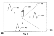
図3は、移動セルラ電話等の移動通信装置のようなユーザ装置(UE)301と、多数のセル302、303、304を含む無線ネットワーク306とを備えるシステム300を示す。セルは、例えばeノードBのような基地局を採用してもよい。
FIG. 3 shows a
セル302、303、304のうちの1つ以上は、例えば、LTE TDDセルであってもよい。代替的には、または、追加的には、セル302、303、304の多くは、例えば、LTE FDDセルであってもよい。
One or more of the
複数のセルのうちの1つ、例えばセル303は、UE301に対するサービングセルであってもよく、それにより、UE301はサービングセル303に接続されてもよく、また、UE301は、例えば、サービングセル303を介して、例えば、電話呼を示すデータと、SMS等を示すデータと、の少なくとも何れかを受信しうる。追加的には、または、代替的には、サービングセル303は、例えば、サービングセル303に接続されたUE301に対して、基準シンボルを送信してもよい。
One of the plurality of cells, eg,
他のセル302、304は、例えば、サービングセル303に隣接するセルであってもよい。他のセル302、304は、例えば、他のセル302、304のそれぞれに接続されたUEに対して、例えば、電話呼を示すデータと、SMS等を示すデータと、の少なくとも何れかを送信しうる。追加的には、または、代替的には、当該他のセルは、例えば、当該他のセルのそれぞれに接続されたUEに対して、基準シンボルを送信してもよい。
The
点線305は、例えば、セル302、303および304がそれぞれのサービングセルである、エリアA、BおよびCのそれぞれを画定するセルエッジを表しうる。
1つの例では、ネットワーク306は、例えば都市内のような高密度のネットワークである場合があり、この場合、ネットワーク306内のいくつかの隣接するセル302、304からの基準シンボルが、サービングセル303の基準シンボルと、部分的にまたは全体的に干渉する可能性がある。
In one example, the
例えば、LTE TDD等のような同期ネットワークでは、セル302、303、304からの基準シンボルが干渉する可能性がある。例えば、LTE FDDでも、セル302、303、304からの基準シンボルが干渉する可能性がある。
For example, in a synchronous network such as LTE TDD, reference symbols from
1つの例では、ネットワーク306は、例えば地方エリアのネットワークのような、低密度のネットワークである場合があり、この場合、ネットワーク306内のいくつかの隣接するセル302、304からの基準シンボルが、サービングセル303の基準シンボルと、実質的に干渉しないか、または部分的に干渉する。ネットワーク306は、例えば、低密度のLTE TDDネットワークまたはLTE FDDネットワークである場合がある。
In one example, the
第3の例では、ネットワーク306は、任意のタイプのネットワークである場合があり、即ち、高密度のネットワークである場合、低密度のネットワークである場合、または、隣接するセル302、304からの基準シンボルがサービングセル303からの基準シンボルと、部分的にもしくは全体的に、干渉しうるか、もしくは干渉しえないようなネットワークであって、高いセル密度のネットワークと低いセル密度のネットワークとの間の範囲内の何れかのセル密度を有するネットワークである場合、がある。
In a third example, the
その結果、サービングセル303に接続されたUE301は、図2bに示すように、LTEリソース・エレメント内で多数の基準シンボル(例えば、4つの基準シンボルRSC, RNC1, RNC2, RNCn)を受信しうる。この場合、LTEリソース・エレメント内の基準シンボルRSCである第1の部分2001は、サービングセル303から送信されてもよく、基準シンボルRNC1, RNC2, ..., RNCnである第2の部分2002は、隣接セル302、304から送信されてもよい。
As a result, the
サービングセル303からの基準シンボルRSCに対する、隣接セル302、304からの(例えば空でない第2の部分2002からの)基準シンボルの干渉を仮定すると、例えばLTEリソース・エレメント2003で、サブキャリアkおよび時間lにおいてUE301で受信される基準シンボルYk,lは、
![]()
![]()
上式(1)では、サービングセルの基準シンボルは1であると仮定している。さらに、Hk,lは、サービングセル303とUE301との間の、時間lにおけるサブキャリアkについてのチャネルを表す。Gk,lは、隣接セル302、304とUE301との間のチャネルの合計値を表しうる。この場合、隣接セルの基準シンボルは、UE301で受信されたサービングセル303の基準シンボルと干渉しうる。ck,lは、隣接セル302、304によって送信された基準シンボルの、サブキャリアkおよび時間lにおけるスクランブリング系列を表しうる。εk,lは、分散が
![]()
![]()
UE301は、チャネル推定値^Hk,lを、例えば上記で開示したように決定しうるとともに、チャネル推定値^Hk,lと受信した基準シンボルYk,lとに基づいて、UE301は、瞬時の雑音干渉推定値ek,lを、チャネル推定値^Hk,lと受信した基準シンボルYk,lとの差分として、次式のように決定しうる。
![]()
![]()
瞬時の雑音干渉推定値ek,lに基づいて、UE301は、第1の雑音干渉電力推定値
![]()
![]()
![]()

![]()
![]()
![]()
![]()
![]()
dは、基準シンボル・スクランブリング系列期間の長さに対応するシンボル数であってもよい。例えば、LTEでは、スクランブリング系列は、10msの周期で周期的であってもよい。10msは、10個のサブフレームに等しい1つの無線フレームに等しい。1つのサブフレームは、通常のサイクリック・プレフィックス長では7シンボル/スロット(拡張サイクリック・プレフィックス長では6シンボル/スロット)のうちの2スロットを含んでいてもよく、これにより、スクランブリング系列期間の長さは、d=7(シンボル/スロット)*2(スロット/サブフレーム)*10(サブフレーム/無線フレーム)*1(無線フレーム)=140(シンボル)であると決定されうる。 d may be the number of symbols corresponding to the length of the reference symbol / scrambling sequence period. For example, in LTE, the scrambling sequence may be periodic with a period of 10 ms. 10 ms is equal to one radio frame equal to 10 subframes. One subframe may include 2 slots out of 7 symbols / slot with a normal cyclic prefix length (6 symbols / slot with an extended cyclic prefix length), so that a scrambling sequence period can be obtained. Can be determined to be d = 7 (symbol / slot) * 2 (slot / subframe) * 10 (subframe / radio frame) * 1 (radio frame) = 140 (symbol).
一実施形態において、雑音干渉電力の推定値は、UE301で
![]()
![]()
![]()
![]()
サービングセルに対する隣接セル・チャネルにおける変化が小さい場合、即ち、例えばUE301が低速(例えば10Hz以下のドップラー周波数)で移動する場合、
![]()
![]()
例えば、2.6GHzの搬送波周波数および10Hzのドップラー周波数は、UEの速度
例えば、700MHzの搬送波周波数および10Hzのドップラー周波数は、UEの速度
その結果、サービングセル303からUE301によって受信される基準シンボルの実際の雑音干渉電力σk,l 2の推定値は、例えば、UEの移動速度が低い場合、即ち、ドップラー周波数でおおよそ10Hz以下である場合、UE301において、雑音干渉電力の推定値
![]()
![]()
このようにして、UE301は、上記の式(7)を用いて、サービングセル303からUE301によって受信される基準シンボルの実際の雑音干渉電力σk,l 2の推定値を、第2の雑音干渉電力推定値
![]()
![]()
UE301が、サービングセル303からUE301によって受信された基準シンボルの実際の雑音干渉電力σk,l 2の推定値を、第1の雑音干渉電力推定値
![]()
![]()
![]()
![]()
![]()
![]()
一実施形態において、UE301は、サービングセル303からUE301によって受信された基準シンボルの、雑音干渉電力の推定値を、
![]()
![]()
![]()
![]()
![]()
![]()
![]()
![]()
![]()
![]()
![]()
![]()
その結果、UE301は、サービングセル303からUE301によって受信された基準シンボルの実際の雑音干渉電力の推定値を
![]()
![]()
追加的に、または、代替的に、高速(例えば10Hzを超えるドップラー周波数)で移動しているUE301においては、実際の雑音干渉電力σk,l 2の推定値は、式(10)で与えられるように決定されうる。この場合、
![]()
![]()
![]()
![]()
![]()
![]()
図4aは、受信信号の品質を決定する一実施形態のフローチャートを示す。 FIG. 4a shows a flowchart of an embodiment for determining the quality of the received signal.
本方法はステップ400において開始する。
The method starts at
ステップ405で、UE301は、セル303等のサービングセルに接続することによって、ネットワーク306に接続しうる。
In
ステップ410で、UE301は、サービングセル303および隣接セル302、304から受信される基準シンボルのスクランブリング系列期間長dを決定しうる。
In
ステップ415で、UE301は、チャネル電力、例えばUE301とサービングセル303との間のチャネルを推定しうる。
In
ステップ420で、UE301は、第1の雑音干渉電力推定値
![]()
![]()
![]()
![]()
![]()
![]()
![]()
![]()
ステップ425で、UE301は、例えば、雑音干渉電力の推定値^σk,l 2を決定し、かつ、それにより実際の雑音干渉電力σk,l 2の推定値を決定するために、上記の式(3)、式(4)および式(9)を用いるように適応されたプロセッサにおいて、雑音干渉電力の推定値を決定しうる。
In
ステップ430で、UE301は、CQI値を決定するために、例えば、σk,l 2をテーブルにおけるインデックスとして用いることによって、σk,l 2をCQI値に関連付けているテーブルからCQI値を決定しうる。当該テーブルは、例えば、UE301のメモリに格納されていてもよい。当該CQI値は、UE301からネットワーク306に、例えば、サービングセル303を介して送信されてもよい。
In
ステッ435で、本方法は終了する。
At
図4bは、受信信号の品質を決定する一実施形態のフローチャートを示す。 FIG. 4b shows a flowchart of an embodiment for determining the quality of the received signal.
本方法はステップ4000において開始する。ステップ4005〜ステップ4015は、図4aのステップ405〜ステップ415と同一である。
The method starts at
ステップ4020で、UE301は、第2の雑音干渉電力推定値
![]()
![]()
![]()
![]()
ステップ4030で、UE301は、CQI値を決定するために、例えば、
![]()
![]()
![]()
![]()
ステップ4035で、本方法は終わる。
At
図5は、受信信号の品質を決定するための装置の実施形態を示す。当該装置500は、例えば、移動通信装置301の一部であってもよい。
FIG. 5 shows an embodiment of an apparatus for determining the quality of a received signal. The
装置500は、アンテナ501を備えうる。例えば、装置500は、移動通信装置301のアンテナ501に接続されうる。アンテナ501は、ネットワーク306から、例えば、サービングセル303を介して信号510を受信しうる。
受信信号510は、例えば、1つ以上の基準シンボルに関するデータと、周期的なスクランブリング系列と、例えば電話呼およびSMS等の少なくとも何れかを示すデータと、の少なくとも何れかを含みうる。
受信信号510は、フロントエンド受信機502においてベースバンド信号にダウンコンバートされうる。ベースバンド信号は、アナログ・フィルタ503においてアナログ・フィルタリングされうるとともに、アナログ・フィルタリングされた信号は、アナログ・デジタル変換器(ADC)504のおいてデジタル信号に変換されうる。デジタル信号は、デジタル・フィルタ505においてデジタル・フィルタリングされうる。
高速フーリエ変換器(FFT)506は、デジタル・フィルタリングされた信号の周波数領域表現を決定しうる。デジタル・フィルタリングされた信号の周波数領域表現から、FFTは、基準シンボルに対応するリソース・エレメントを決定しうるとともに、当該リソース・エレメントは、チャネル・干渉推定器508に送信されうる。基準シンボルに対応するリソース・エレメントを決定するために、FFTは、例えば、UE301に含まれるセルサーチ部からタイミング情報512を受信して利用しうる。当該タイミング情報は、例えば1次同期信号および2次同期信号から、セルサーチ部によって決定されうる。
A Fast Fourier Transform (FFT) 506 may determine a frequency domain representation of the digital filtered signal. From the frequency domain representation of the digital filtered signal, the FFT can determine a resource element corresponding to the reference symbol and the resource element can be transmitted to the channel and
チャネル・干渉推定器508は、例えば、実際の雑音干渉電力σk,l 2の推定値を、式(7)に基づいて決定しうる。さらに、チャネル・干渉推定器508は、例えば、実際の雑音干渉電力σk,l 2の推定値を、式(8)に基づいて決定しうる。実際の雑音干渉電力σk,l 2の推定値を式(7)に基づいて決定するために、チャネル・干渉推定器508は、基準シンボルの周期性に関する情報511を受信しうる。基準シンボルの周期性は、例えば、セル識別に関する情報、およびサイクリック・プレフィックス長(拡張サイクリック・プレフィックス長では6シンボル、通常のサイクリック・プレフィックス長では7シンボル)に基づいて決定されうる。サイクリック・プレフィックス長およびセル識別情報は、例えば、ネットワークからサービングセルを介して受信されうる。チャネル・干渉推定器508は、例えば、基準シンボル・スクランブリング系列期間長d(即ち、基準シンボル・スクランブリングの周期性)を、セルサーチ中に多くの間接的な推定から決定しうるか、または、チャネル・干渉推定器508は、例えば、サービングセルを介して、隣接セルリストにおいて基準シンボル・スクランブリング系列期間長dを受信しうる。
For example, the channel /
実際の雑音干渉電力σk,l 2の、式(7)および式(8)に基づく推定値は、チャネル・干渉推定器508から制御部509に送信されうる。制御部509は、例えば、実際の雑音干渉電力σk,l 2の、式(7)および式(8)を用いて得られた推定値のうちの最小値を決定しうる。制御部509は、例えば、SINR、推定されたプリコーディング行列、およびランクをインデックスとして用いたテーブル内の検索によって、SINR、プリコーディング行列、およびランクを、CQI値にマッピングしうる。一例では、ランクおよびプリコーディング行列は、チャネル推定値および雑音推定値から決定されうる。制御部509は、当該CQIをネットワーク306に、例えばサービングセル303を介して送信しうる。
The estimated value based on the equations (7) and (8) of the actual noise interference power σ k, l 2 can be transmitted from the channel /
一実施形態において、装置500は検出器507を備えうる。検出器507は、例えば、チャネル・干渉推定器508から受信したチャネル推定値と、FFT506から受信したシンボルとを利用して、データ復調を実行しうる。
In one embodiment, the
一実施形態において、装置500は、
![]()
![]()
![]()
![]()
![]()
![]()
![]()
![]()
![]()
![]()
![]()
![]()
![]()
![]()
![]()
![]()
一実施形態において、受信機513は、フロントエンド受信器502と、アナログ・フィルタ503と、アナログ・デジタル変換器504と、デジタル・フィルタ505とを備えうる。
In one embodiment, the
図6は、CQIを決定するために一実施形態を利用する利点の一例を示す。図6の例ででは、隣接セル302、304の基準シンボルは、サービングセル303の基準シンボルの電力よりも10dB低い電力を有すると仮定している。
FIG. 6 illustrates an example of the benefits of using one embodiment to determine CQI. In the example of FIG. 6, it is assumed that the reference symbols of neighboring
実際のSINRの軸は、dB単位での実際のSINRのレベルを表している。報告されたSINRの軸は、5Hzのドップラー周波数で移動しており、かつ、式(7)を用いるSINR推定601、および式(8)を用いるSINR推定602をそれぞれ実行する移動通信装置によって報告されたSINRを表す。
The actual SINR axis represents the actual SINR level in dB. The reported SINR axis is moving at a Doppler frequency of 5 Hz and is reported by the mobile communication device performing
同図からわかるように、式(7)は実際の雑音干渉電力を式(8)よりも正確に近似でき、その結果、例えば低いドップラー周波数で式(7)を用いてCQIを報告するUE301は、式(8)を用いてCQIを報告するUEよりも高いデータレートを、サービングセル303から得ることができる。
As can be seen from the figure, Equation (7) can approximate the actual noise interference power more accurately than Equation (8). As a result, for example,
一態様において、エンティティの一部(例えば、受信した基準シンボル)は、例えば、当該エンティティの全体(例えば受信した基準シンボルの全体)を備えうるか、あるいは、当該エンティティの一部は、当該エンティティの適切な部分集合を備えうる。受信した基準シンボルの第1の部分と第2の部分との和は、受信した基準シンボルに等しい。 In one aspect, a portion of an entity (eg, a received reference symbol) may comprise, for example, the entire entity (eg, an entire received reference symbol), or a portion of the entity may be appropriate for the entity. Can be a subset. The sum of the first part and the second part of the received reference symbol is equal to the received reference symbol.
本発明の様々な実施形態について説明し、かつ、示してきたが、本発明はそれらに限定されず、以下の特許請求の範囲で規定されている主題の範囲内で、他の方法においても実施可能である。 While various embodiments of the invention have been described and illustrated, the invention is not so limited and may be practiced in other ways within the scope of the subject matter defined in the following claims. Is possible.
一般に、上記および/または下記の技術的特徴および/または実施形態の何れもが、1つの実施形態に組み合わされてもよい。代替的には、または、追加的には、上記および/または下記の技術的特徴および/または実施形態のいずれもが、別個の実施形態であってもよい。代替的には、または、追加的には、任意の数の実施形態を生み出すために、上記および/または下記の技術的特徴および/または実施形態のいずれもが、上記および/または下記の他の技術的特徴および/または他の実施形態と組み合わされてもよい。 In general, any of the above and / or below described technical features and / or embodiments may be combined into one embodiment. Alternatively or additionally, any of the above and / or below described technical features and / or embodiments may be separate embodiments. Alternatively, or additionally, any of the technical features and / or embodiments described above and / or below may be used to produce any number of embodiments described above and / or other It may be combined with technical features and / or other embodiments.
いくつかの手段を列挙している装置の請求項では、これらの手段のいくつかが同一品目のハードウェアによって実施できる。ある測度が、相互に異なる従属請求項に記載されている、または種々の実施形態で説明されているという単なる事実は、これらの測度の組み合わせが、利点を得るために使用され得ないということは示していない。 In the device claim enumerating several means, several of these means can be embodied by one and the same item of hardware. The mere fact that certain measures are recited in mutually different dependent claims or described in various embodiments does not indicate that a combination of these measures cannot be used to obtain an advantage. Not shown.
「備える/備えている」という用語は、本明細書で使用される場合、記述した特徴、整数、ステップ、または構成要素の存在を特定すると解釈されるものの、1つ以上の他の特徴、整数、ステップ、構成要素、またはそれらの集合の存在または追加を排除しないことが、強調されるべきである。 The term “comprising / comprising” as used herein is intended to identify the presence of the described feature, integer, step, or component, but one or more other features, integer It should be emphasized that it does not exclude the presence or addition of steps, components, or collections thereof.
Claims (14)
第1の部分(2001)および第2の部分(2002)を含む信号(510)を受信するステップであって、当該受信信号の少なくとも前記第2の部分がスクランブリング系列期間を含む、ステップと、
前記受信信号に含まれる前記第2の部分についての干渉を、前記スクランブリング系列期間を利用して除去することによって、前記受信信号の前記第1の部分についての第1の雑音干渉電力を決定するステップ(420; 4020)と
を含み、
前記第1の部分(2001)は、サービングセルから送信された基準シンボルを含み、
前記第2の部分(2002)は、隣接セルから送信された基準シンボルを含む
ことを特徴とする方法。 A method for determining the quality of a received signal (510), comprising:
Receiving a signal (510) comprising a first part (2001) and a second part (2002), wherein at least the second part of the received signal comprises a scrambling sequence period;
A first noise interference power for the first portion of the received signal is determined by removing interference for the second portion included in the received signal using the scrambling sequence period. Step (420; 4020), and
The first part (2001) includes a reference symbol transmitted from a serving cell;
The method of claim 2, wherein the second part (2002) includes a reference symbol transmitted from a neighboring cell.
第1の時間におけるチャネル推定値および受信信号の差分と、第2の時間におけるチャネル推定値および受信信号の差分と、の差分のエルミート共役について、第1の周波数区間および第1の時間区間の範囲にわたる総和を求めるステップを含み、
前記エルミート共役には、前記第1の時間におけるチャネル推定値および受信信号の差分と、前記第2の時間におけるチャネル推定値および受信信号の差分と、の差分が乗算され、
前記第1の時間と前記第2の時間との間の前記差分は、前記スクランブリング系列期間の倍数に等しい
ことを特徴とする請求項1に記載の方法。 Said step of determining a first noise interference power comprises:
The range of the first frequency interval and the first time interval for Hermitian conjugate of the difference between the channel estimation value and the received signal at the first time and the difference between the channel estimation value and the received signal at the second time Including the step of calculating the sum over
The Hermitian conjugate is multiplied by the difference between the difference between the channel estimate and the received signal at the first time and the difference between the channel estimate and the received signal at the second time,
The method of claim 1, wherein the difference between the first time and the second time is equal to a multiple of the scrambling sequence period.
Kbias/2は定数であり、
Hは、エルミート共役を表し、
dは、スクランブリング系列期間の長さを含む
ことを特徴とする請求項1に記載の方法。 Said step of determining a first noise interference power comprises:
K bias / 2 is a constant,
H represents Hermitian conjugate,
The method of claim 1, wherein d includes the length of a scrambling sequence period.
前記エルミート共役には、チャネル推定値と受信信号との差分が乗算されており、
前記方法は、さらに、前記第1の雑音干渉電力および前記第2の雑音干渉電力のうちの最小値を決定するステップ(425)を含む
ことを特徴とする請求項1乃至3の何れか1項に記載の方法。 Determining (420) a second noise interference power by determining a sum of Hermitian conjugates of the difference between the channel estimate and the received signal over a first frequency interval and a first time interval;
The Hermite conjugate is multiplied by the difference between the channel estimate and the received signal,
4. The method of claim 1, further comprising the step of determining (425) a minimum value of the first noise interference power and the second noise interference power. The method described in 1.
前記第1の雑音干渉電力が前記第2の雑音干渉電力と実質的に等しい場合には、前記受信信号に含まれる前記第1の部分と前記第2の部分との間の干渉は他のソースに起因していると判定し、それ以外の場合には、当該干渉は隣接干渉に起因していると判定するステップと
をさらに含むことを特徴とする請求項4に記載の方法。 Comparing the first noise interference power with the second noise interference power;
The first when the noise interference power is substantially equal to the second noise interference power, interference other source between the first portion and the second portion are included in the reception signal The method of claim 4, further comprising: determining that the interference is caused by a source, and otherwise determining that the interference is caused by adjacent interference.
ユーザ装置の速度が10Hz以下のドップラー周波数の範囲内である場合には、前記第1の雑音干渉電力として決定され、
それ以外の場合には、前記第1の雑音干渉電力および前記第2の雑音干渉電力のうちの前記最小値として決定される
ことを特徴とする請求項4乃至6の何れか1項に記載の方法。 The quality of the received signal is
When the speed of the user equipment is within the range of the Doppler frequency of 10 Hz or less, it is determined as the first noise interference power,
In any other case, the minimum value of the first noise interference power and the second noise interference power is determined. 7. Method.
第1の部分(2001)および第2の部分(2002)を含む信号(510)を受信する少なくとも1つの受信機(513)であって、当該受信信号の少なくとも前記第2の部分がスクランブリング系列期間を含む、少なくとも1つの受信機と、
前記受信信号に含まれる前記第2の部分についての干渉を、前記スクランブリング系列期間の長さを利用して除去することによって、前記受信信号の前記第1の部分についての第1の雑音干渉電力を決定する少なくとも1つの推定器(508)と
を備え、
前記第1の部分(2001)は、サービングセルから送信された基準シンボルを含み、
前記第2の部分(2002)は、隣接セルから送信された基準シンボルを含む
ことを特徴とする装置。 A device for determining the quality of a received signal (510),
At least one receiver (513) for receiving a signal (510) comprising a first part (2001) and a second part (2002), wherein at least the second part of the received signal is a scrambling sequence At least one receiver including a period;
A first noise interference power for the first portion of the received signal by removing interference for the second portion included in the received signal using a length of the scrambling sequence period. And at least one estimator (508) for determining
The first part (2001) includes a reference symbol transmitted from a serving cell;
The second part (2002) includes a reference symbol transmitted from a neighboring cell.
第1の時間におけるチャネル推定値および受信信号の差分と、第2の時間におけるチャネル推定値および受信信号の差分と、の差分のエルミート共役について、第1の周波数区間および第1の時間区間の範囲にわたる総和を求めることによって、前記第1の雑音干渉電力を決定し、
前記エルミート共役には、前記第1の時間におけるチャネル推定値および受信信号の差分と、前記第2の時間におけるチャネル推定値および受信信号の差分と、の差分が乗算され、
前記第1の時間と前記第2の時間との間の前記差分は、前記スクランブリング系列期間の倍数に等しい
ことを特徴とする請求項8に記載の装置。 The at least one estimator is
The range of the first frequency interval and the first time interval for Hermitian conjugate of the difference between the channel estimation value and the received signal at the first time and the difference between the channel estimation value and the received signal at the second time Determining the first noise interference power by determining the sum over
The Hermitian conjugate is multiplied by the difference between the difference between the channel estimate and the received signal at the first time and the difference between the channel estimate and the received signal at the second time,
9. The apparatus of claim 8, wherein the difference between the first time and the second time is equal to a multiple of the scrambling sequence period.
前記エルミート共役には、チャネル推定値と受信信号との差分が乗算されており、
前記装置は、さらに、前記第1の雑音干渉電力および前記第2の雑音干渉電力のうちの最小値を決定する
ことを特徴とする請求項8または9に記載の装置。 The at least one estimator (508) further determines a second noise interference by determining a sum of Hermitian conjugates of the difference between the channel estimate and the received signal over the first frequency interval and the first time interval. Determine the power,
The Hermite conjugate is multiplied by the difference between the channel estimate and the received signal,
The apparatus according to claim 8, wherein the apparatus further determines a minimum value of the first noise interference power and the second noise interference power.
前記少なくとも1つの推定器は、
前記第1の雑音干渉電力が前記第2の雑音干渉電力と実質的に等しい場合には、前記受信信号に含まれる前記第1の部分と前記第2の部分との間の干渉は他のソースに起因していると判定し、それ以外の場合には、当該干渉は隣接セル干渉に起因していると判定する
ことを特徴とする請求項10に記載の装置。 The at least one estimator further compares the first noise interference power with the second noise interference power;
The at least one estimator is
The first when the noise interference power is substantially equal to the second noise interference power, interference other source between the first portion and the second portion are included in the reception signal The apparatus according to claim 10, wherein the apparatus determines that the interference is caused by a source cell, and otherwise determines that the interference is caused by adjacent cell interference.
ユーザ装置の速度が10Hz以下のドップラー周波数の範囲内である場合には、受信信号の前記品質を、前記第1の雑音干渉電力として決定し、
それ以外の場合には、受信信号の前記品質を、前記第1の雑音干渉電力および前記第2の雑音干渉電力のうちの前記最小値として決定する
ことを特徴とする請求項10乃至12の何れか1項に記載の装置。 The device is
If the speed of the user equipment is within a range of Doppler frequency of 10 Hz or less, the quality of the received signal is determined as the first noise interference power;
In any other case, the quality of the received signal is determined as the minimum value of the first noise interference power and the second noise interference power. The apparatus according to claim 1.
請求項8乃至13の何れか1項に記載の装置と、
サービングセルと、
少なくとも1つの隣接セルと
を備えることを特徴とするシステム。 A system for determining the quality of a received signal,
An apparatus according to any one of claims 8 to 13, and
Serving cell,
A system comprising at least one neighboring cell.
Applications Claiming Priority (5)
| Application Number | Priority Date | Filing Date | Title |
|---|---|---|---|
| EP08162581A EP2157717B1 (en) | 2008-08-19 | 2008-08-19 | Method and system and device for CQI estimation disturbance cancellation |
| EP08162581.6 | 2008-08-19 | ||
| US9029308P | 2008-08-20 | 2008-08-20 | |
| US61/090,293 | 2008-08-20 | ||
| PCT/EP2009/058812 WO2010020478A1 (en) | 2008-08-19 | 2009-07-10 | Method and system and device for cqi estimation disturbance cancellation |
Publications (3)
| Publication Number | Publication Date |
|---|---|
| JP2012500545A JP2012500545A (en) | 2012-01-05 |
| JP2012500545A5 JP2012500545A5 (en) | 2012-08-16 |
| JP5421992B2 true JP5421992B2 (en) | 2014-02-19 |
Family
ID=40279132
Family Applications (1)
| Application Number | Title | Priority Date | Filing Date |
|---|---|---|---|
| JP2011523367A Expired - Fee Related JP5421992B2 (en) | 2008-08-19 | 2009-07-10 | Method, system and apparatus for interference cancellation of CQI estimation |
Country Status (7)
| Country | Link |
|---|---|
| US (1) | US8503946B2 (en) |
| EP (1) | EP2157717B1 (en) |
| JP (1) | JP5421992B2 (en) |
| DK (1) | DK2157717T3 (en) |
| MX (1) | MX2011001282A (en) |
| MY (1) | MY154719A (en) |
| WO (1) | WO2010020478A1 (en) |
Families Citing this family (11)
| Publication number | Priority date | Publication date | Assignee | Title |
|---|---|---|---|---|
| JP5059062B2 (en) * | 2009-07-08 | 2012-10-24 | シャープ株式会社 | COMMUNICATION SYSTEM, MOBILE STATION DEVICE, AND BASE STATION DEVICE |
| US8526552B1 (en) * | 2009-08-25 | 2013-09-03 | Marvell International Ltd. | Noise estimation in communication receivers |
| CN102055704B (en) * | 2009-11-10 | 2013-05-08 | 中兴通讯股份有限公司 | Method and device for noise estimation in orthogonal frequency division multiplexing (OFDM) system |
| KR101895947B1 (en) | 2010-01-18 | 2018-09-07 | 엘지전자 주식회사 | A method and an apparatus for providing channel quality information in a wireless communication system |
| WO2011109940A1 (en) | 2010-03-11 | 2011-09-15 | Qualcomm Incorporated | Method and apparatus for enabling enhanced cqi update frequency |
| US8730861B2 (en) * | 2010-06-21 | 2014-05-20 | Qualcomm Incorporated | Rate matching for data and control channels in wireless communication systems |
| US8483641B1 (en) | 2010-07-28 | 2013-07-09 | Marvell International Ltd. | Validation and stabilization of noise matrices |
| EP2557706B1 (en) | 2011-08-12 | 2014-03-05 | TELEFONAKTIEBOLAGET LM ERICSSON (publ) | Channel quality index determination |
| US9078205B2 (en) * | 2012-03-09 | 2015-07-07 | Qualcomm Incorporated | Methods and apparatus for enabling non-destaggered channel estimation |
| JP6997625B2 (en) * | 2016-01-29 | 2022-01-17 | 株式会社Nttドコモ | Terminals, wireless communication methods, base stations and systems |
| JP6832794B2 (en) * | 2017-06-05 | 2021-02-24 | ルネサスエレクトロニクス株式会社 | Wireless communication system |
Family Cites Families (6)
| Publication number | Priority date | Publication date | Assignee | Title |
|---|---|---|---|---|
| US6301293B1 (en) * | 1998-08-04 | 2001-10-09 | Agere Systems Guardian Corp. | Detectors for CDMA systems |
| US7061967B2 (en) * | 2002-06-24 | 2006-06-13 | Comsys Communication & Signal Processing Ltd. | Multipath channel tap delay estimation in a CDMA spread spectrum receiver |
| JP4557762B2 (en) * | 2005-03-17 | 2010-10-06 | 富士通株式会社 | Method for measuring communication environment of mobile station and mobile station |
| WO2007021159A2 (en) * | 2005-08-19 | 2007-02-22 | Samsung Electronics Co., Ltd. | Cinr estimating method and device using preamble in ofdm |
| KR100834815B1 (en) * | 2006-03-03 | 2008-06-05 | 삼성전자주식회사 | Apparatus and method for measuring sinr using preamble in mobile communication system |
| JP5268237B2 (en) * | 2006-07-28 | 2013-08-21 | シャープ株式会社 | Scheduling method, communication control device, and terminal device |
-
2008
- 2008-08-19 DK DK08162581.6T patent/DK2157717T3/en active
- 2008-08-19 EP EP08162581A patent/EP2157717B1/en not_active Not-in-force
-
2009
- 2009-07-10 JP JP2011523367A patent/JP5421992B2/en not_active Expired - Fee Related
- 2009-07-10 US US13/059,892 patent/US8503946B2/en active Active
- 2009-07-10 MY MYPI2011000385A patent/MY154719A/en unknown
- 2009-07-10 WO PCT/EP2009/058812 patent/WO2010020478A1/en active Application Filing
- 2009-07-10 MX MX2011001282A patent/MX2011001282A/en active IP Right Grant
Also Published As
| Publication number | Publication date |
|---|---|
| EP2157717A1 (en) | 2010-02-24 |
| EP2157717B1 (en) | 2013-03-27 |
| MX2011001282A (en) | 2011-03-04 |
| JP2012500545A (en) | 2012-01-05 |
| US8503946B2 (en) | 2013-08-06 |
| WO2010020478A1 (en) | 2010-02-25 |
| US20110305268A1 (en) | 2011-12-15 |
| DK2157717T3 (en) | 2013-05-06 |
| MY154719A (en) | 2015-07-15 |
Similar Documents
| Publication | Publication Date | Title |
|---|---|---|
| JP5421992B2 (en) | Method, system and apparatus for interference cancellation of CQI estimation | |
| US8670465B2 (en) | Radio communication method and a base station and user terminal thereof | |
| TWI411270B (en) | Pilot signal transmission for an orthogonal frequency division wireless communication system | |
| US20170141900A1 (en) | Apparatus and Methods for Wireless Channel Sounding | |
| US8131228B2 (en) | Interference based phase shift precoding for OFDM | |
| CN105391671B (en) | Method and apparatus for channel estimation and equalization | |
| JP5844424B2 (en) | Method, device and user equipment for removing interference | |
| US20120106388A1 (en) | Communication system, communication apparatus and communication method | |
| US20120014476A1 (en) | Pilot Aided Data Transmission and Reception with Interference Mitigation in Wireless Systems | |
| EP3113395B1 (en) | Wireless base station, user terminal, wireless communication method and wireless communication system | |
| US20110158343A1 (en) | Method and apparatus for estimating channel using phase compensation in wireless communication system | |
| CN104937873A (en) | Methods and nodes in a wireless communication system | |
| US10211915B2 (en) | Feedback method and apparatus for transmitting and receiving multicarrier signal in wireless mobile communication system | |
| WO2011052222A1 (en) | Wireless communication apparatus and reference signal generating method | |
| US9300374B2 (en) | Communications terminal, apparatus, and method for detecting rank indication | |
| EP2806611A1 (en) | Offset estimation using channel state information reference symbols and demodulation reference symbols | |
| US9100961B2 (en) | Methods and devices for handling reference signals in a communications network | |
| Narasimhan et al. | Channel estimation and co-channel interference rejection for LTE-Advanced MIMO uplink | |
| JP2015201804A (en) | Receiver, reception method, transmitter, transmission method, and radio communication system | |
| CN112838915A (en) | Physical signal transmission method, terminal and base station | |
| KR20140129973A (en) | Additional Wireless Resource Allocation for Demodulation Reference Signal by Using Common Reference Signal for Small Cell Networks | |
| KR20070094782A (en) | Frequency division communication system | |
| KR20110097021A (en) | Method and apparatus for transmitting and receiving pilot in wireless telecommunications system | |
| Hejazi | Synchronization requirements for downlink coordinated multipoint joint transmission | |
| KR20180031538A (en) | Communication apparatus and method for controlling interference in multiple input multiple output communication system |
Legal Events
| Date | Code | Title | Description |
|---|---|---|---|
| A521 | Written amendment |
Free format text: JAPANESE INTERMEDIATE CODE: A523 Effective date: 20120626 |
|
| A621 | Written request for application examination |
Free format text: JAPANESE INTERMEDIATE CODE: A621 Effective date: 20120626 |
|
| A977 | Report on retrieval |
Free format text: JAPANESE INTERMEDIATE CODE: A971007 Effective date: 20130730 |
|
| A131 | Notification of reasons for refusal |
Free format text: JAPANESE INTERMEDIATE CODE: A131 Effective date: 20130805 |
|
| A521 | Written amendment |
Free format text: JAPANESE INTERMEDIATE CODE: A523 Effective date: 20130925 |
|
| TRDD | Decision of grant or rejection written | ||
| A01 | Written decision to grant a patent or to grant a registration (utility model) |
Free format text: JAPANESE INTERMEDIATE CODE: A01 Effective date: 20131105 |
|
| A61 | First payment of annual fees (during grant procedure) |
Free format text: JAPANESE INTERMEDIATE CODE: A61 Effective date: 20131122 |
|
| R150 | Certificate of patent or registration of utility model |
Ref document number: 5421992 Country of ref document: JP Free format text: JAPANESE INTERMEDIATE CODE: R150 |
|
| R250 | Receipt of annual fees |
Free format text: JAPANESE INTERMEDIATE CODE: R250 |
|
| R250 | Receipt of annual fees |
Free format text: JAPANESE INTERMEDIATE CODE: R250 |
|
| R250 | Receipt of annual fees |
Free format text: JAPANESE INTERMEDIATE CODE: R250 |
|
| R250 | Receipt of annual fees |
Free format text: JAPANESE INTERMEDIATE CODE: R250 |
|
| LAPS | Cancellation because of no payment of annual fees |