JP5419059B2 - Torque converter with cover plate attached directly to the piston - Google Patents
Torque converter with cover plate attached directly to the piston Download PDFInfo
- Publication number
- JP5419059B2 JP5419059B2 JP2008182511A JP2008182511A JP5419059B2 JP 5419059 B2 JP5419059 B2 JP 5419059B2 JP 2008182511 A JP2008182511 A JP 2008182511A JP 2008182511 A JP2008182511 A JP 2008182511A JP 5419059 B2 JP5419059 B2 JP 5419059B2
- Authority
- JP
- Japan
- Prior art keywords
- cover plate
- piston
- rivet
- torque converter
- hole
- Prior art date
- Legal status (The legal status is an assumption and is not a legal conclusion. Google has not performed a legal analysis and makes no representation as to the accuracy of the status listed.)
- Expired - Fee Related
Links
Images
Classifications
-
- F—MECHANICAL ENGINEERING; LIGHTING; HEATING; WEAPONS; BLASTING
- F16—ENGINEERING ELEMENTS AND UNITS; GENERAL MEASURES FOR PRODUCING AND MAINTAINING EFFECTIVE FUNCTIONING OF MACHINES OR INSTALLATIONS; THERMAL INSULATION IN GENERAL
- F16H—GEARING
- F16H45/00—Combinations of fluid gearings for conveying rotary motion with couplings or clutches
- F16H45/02—Combinations of fluid gearings for conveying rotary motion with couplings or clutches with mechanical clutches for bridging a fluid gearing of the hydrokinetic type
-
- F—MECHANICAL ENGINEERING; LIGHTING; HEATING; WEAPONS; BLASTING
- F16—ENGINEERING ELEMENTS AND UNITS; GENERAL MEASURES FOR PRODUCING AND MAINTAINING EFFECTIVE FUNCTIONING OF MACHINES OR INSTALLATIONS; THERMAL INSULATION IN GENERAL
- F16H—GEARING
- F16H41/00—Rotary fluid gearing of the hydrokinetic type
- F16H41/24—Details
- F16H41/28—Details with respect to manufacture, e.g. blade attachment
-
- F—MECHANICAL ENGINEERING; LIGHTING; HEATING; WEAPONS; BLASTING
- F16—ENGINEERING ELEMENTS AND UNITS; GENERAL MEASURES FOR PRODUCING AND MAINTAINING EFFECTIVE FUNCTIONING OF MACHINES OR INSTALLATIONS; THERMAL INSULATION IN GENERAL
- F16H—GEARING
- F16H45/00—Combinations of fluid gearings for conveying rotary motion with couplings or clutches
- F16H45/02—Combinations of fluid gearings for conveying rotary motion with couplings or clutches with mechanical clutches for bridging a fluid gearing of the hydrokinetic type
- F16H2045/0221—Combinations of fluid gearings for conveying rotary motion with couplings or clutches with mechanical clutches for bridging a fluid gearing of the hydrokinetic type with damping means
- F16H2045/0226—Combinations of fluid gearings for conveying rotary motion with couplings or clutches with mechanical clutches for bridging a fluid gearing of the hydrokinetic type with damping means comprising two or more vibration dampers
-
- Y—GENERAL TAGGING OF NEW TECHNOLOGICAL DEVELOPMENTS; GENERAL TAGGING OF CROSS-SECTIONAL TECHNOLOGIES SPANNING OVER SEVERAL SECTIONS OF THE IPC; TECHNICAL SUBJECTS COVERED BY FORMER USPC CROSS-REFERENCE ART COLLECTIONS [XRACs] AND DIGESTS
- Y10—TECHNICAL SUBJECTS COVERED BY FORMER USPC
- Y10T—TECHNICAL SUBJECTS COVERED BY FORMER US CLASSIFICATION
- Y10T29/00—Metal working
- Y10T29/49—Method of mechanical manufacture
- Y10T29/49316—Impeller making
- Y10T29/4933—Fluid coupling device
Landscapes
- Engineering & Computer Science (AREA)
- General Engineering & Computer Science (AREA)
- Mechanical Engineering (AREA)
- Mechanical Operated Clutches (AREA)
Description
本発明は、概して液圧式トルクコンバータ、特にロックアップクラッチを有する液圧式トルクコンバータに関する。 The present invention relates generally to hydraulic torque converters, and more particularly to a hydraulic torque converter having a lock-up clutch.
発明の背景
引用したことにより本明細書に記載されたものとする米国特許第4693348号明細書、米国特許第6325191号明細書、及び米国特許第6615962号明細書には、ロックアップクラッチを備えた液圧式トルクコンバータが記載されている。
BACKGROUND OF THE INVENTION US Pat. No. 4,693,348, US Pat. No. 6,325,191, and US Pat. No. 6,615,962, which are hereby incorporated by reference, have lock-up clutches. A hydraulic torque converter is described.
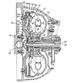
図1は、エンジンからトルクを受け取るためにクランクシャフト14に回転不能に結合されたハウジング12を有する従来の液圧式トルクコンバータ10の例を示している。ハウジング12は、固定されかつシールされた、例えば溶接された同軸的なシェル16及び18を有する。ハウジング12には、ハウジング12と同軸でかつハウジング12の角速度を共有するポンプ20が取り付けられている。
FIG. 1 shows an example of a conventional
ハウジング12には、ハウジング12に関して回転可能なタービン22と、ポンプ20とタービン22との間に据え付けられたステータ24とが収容されている。タービン22はタービンハブ26に回転不能に結合されており、タービンハブ26は、スプライン30によってトランスミッションの入力シャフト28に回転不能に結合されている。ステータ24は、スプライン34によって中空の、回転しないステータシャフト36に結合された一方向クラッチ32に取り付けられている。
The
従来のトルクコンバータ10は、さらに、ハウジング12とタービンハブ26との間で直接にトルクを伝達するために係合させられることができるロックアップクラッチ38を有する。これは、ハウジング12の摩擦面44と接触したピストン42の摩擦面40を位置決めすることによって達成される。ピストン42は、タービンハブ26の周囲を周方向及び軸方向に可動である。タービンハブ26に対するピストン42の軸方向移動は、ピストン42のそれぞれの軸方向の側における作動流体領域45及び46の圧力差を生ぜしめることによって達成される。
The
ロックアップクラッチ38はねじれ振動ダンパ48をも有しており、このねじれ振動ダンパは、駆動プレート50と、カバープレート52,54と、コイルばねのグループ又はその他の弾性エネルギ貯蔵装置56と、リベット又はスペーサボルト58とを有している。駆動プレート50は、スプライン又は突出部60によってピストン42に結合されている。カバープレート52,54は、ばね56を保持しており、リベット又はスペーサボルト58によって一緒に保持されている。カバープレート52,54は、タービン22及びタービンハブ26に堅固に結合されている。カバープレート52,54と駆動プレート50との相対周方向移動は、ばね56を圧縮又は圧縮解除する。これにより、ねじれダンパ48は、例えばクランクシャフト14又はエンジンから伝わるねじれ振動からタービンハブ26を隔離する。
The lock-
本発明の課題は、別個のリベット又はスペーサボルトを用いることなくカバープレートをピストンに直接に取り付けることにより、空間を節約することである。 The object of the present invention is to save space by attaching the cover plate directly to the piston without using separate rivets or spacer bolts.
本発明は、タービンと、ピストンを有するロックアップクラッチと、少なくとも1つのカバープレートを有するダンパが設けられており、カバープレートが直接ピストンに取り付けられているトルクコンバータを提供する。 The present invention provides a torque converter provided with a turbine, a lock-up clutch having a piston, and a damper having at least one cover plate, the cover plate being directly attached to the piston.
本発明は、カバープレートに設けられた孔にピストンの区分を通過させるステップと、孔においてピストンをカバープレートに取り付けるステップとを含むトルクコンバータを組み立てる方法をも提供する。 The present invention also provides a method of assembling a torque converter that includes passing a section of a piston through a hole provided in the cover plate and attaching the piston to the cover plate at the hole.
本発明は、図面を用いて1つの実施形態に関してさらに説明される。 The invention will be further described with respect to one embodiment using the drawings.
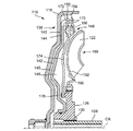
図2は、本発明を具体化するトルクコンバータ110の区分を示している。トルクコンバータ110は、エンジンのクランクシャフトに結合されたハウジングシェル116を有する。ハウジングシェル116内には、タービンハブ126に堅固に結合されたタービン122が設けられている。タービンハブ126は、例えばスプライン130によってトランスミッションの入力シャフト128に回転不能に結合されている。つまり、エンジンは入力シャフト128を中心軸線CAを中心に回転させる。
FIG. 2 shows a section of the
トルクコンバータ110は、さらに、ハウジングシェル116とタービンハブ126との間で直接にトルクを伝達するために係合させられることができるロックアップクラッチ138を有する。この係合は、ピストン142の摩擦面140をハウジングシェル116の摩擦面144と接触して位置決めすることによって達成される。ピストン142は、タービンハブ126の周囲を周方向及び軸方向に可動である。タービンハブ126に対するピストン142の軸方向移動は、ピストン142のそれぞれの軸方向の側における作動流体領域145及び146の圧力差を生ぜしめることによって達成される。
ロックアップクラッチ138は、例えばクランクシャフト又はエンジンによって生ぜしめられるねじれ振動からタービンハブ126を隔離するためのねじれ振動ダンパ148を有する。ダンパ148は、コイルばね又はその他の弾性エネルギ貯蔵装置156の配列と、弾性エネルギ貯蔵装置156を保持するカバープレート152,154とを有する。カバープレート152,154は、ピストン142の外周面172から突出したリベット170によってピストン142に結合されている。フランジ174は、例えばスプライン176によってタービンハブ126に回転不能に結合されている。カバープレート152,154とフランジ174との相対移動はばね156を圧縮又は圧縮解除する。
The lock-
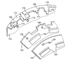
図3は、組立て前における、(概して、環状であることを示すために湾曲して示された)ピストン142の外側部分の区分と、カバープレート152,154とを示している。ピストン142の外面172は、交互に設けられた肩部178及び180を有する凹凸のあるジオメトリを備えてスタンピングされており、肩部はそれぞれピストン142の全体から軸方向距離X1及びX2だけ延びており、X1がX2よりも大きい。さらにリベット170及び171が軸方向に突出しており、リベットはそれぞれ断面が矩形であり、肩部178及び180に取り付けられている。リベット170及び171は、それぞれピストン142の全体から軸方向距離X3及びX4だけ延びており、X3はX4よりも大きい。距離X1はX2とX4との間であることができる。カバープレート152,154は、ばね156を保持するための切欠き185,187を有する。
FIG. 3 shows the section of the outer portion of the piston 142 (shown generally curved to show that it is annular) and the
カバープレート152,154は、ピストン142の凹凸のあるジオメトリ及びリベット170,171を受容するための孔182,186及びスロット184を有する。内側のカバープレート152は、リベット171と同じ断面の孔182と、肩部178と同じ断面のスロット184とを有する。内側のカバープレート152は、肩部180に設けられたリベット171が孔182を貫通し、肩部178がスロット184を貫通するように、ピストン142に組み付けられる。外側のカバープレート154は、リベット170と同じ断面の孔186を有する。外側のカバープレート154は、肩部178に設けられたリベット170が孔186を貫通するようにピストン142に組み付けられる。外側のカバープレート152が適切にピストン142に着座させられると、リベット172が圧潰され、カバープレート152を所定の位置に固定する。次に、カバープレート154がピストン142に着座させられると、リベット170が圧潰され、カバープレート154を所定の位置に固定する。リベット171は、カバープレート154が着座させられる前に圧潰されている。
The
カバープレート152,154を直接ピストン142に取り付けることは、有利には、図2に示されたタービンアセンブリ188を平衡させるための空間を節約する。タービンアセンブリ188は、一般的に、タービンシェル192の外面190に取り付けられたおもりによって平衡される。おもりは一般的に、タービンシェル192に対して垂直に組み立てられるので、従来のダンパ、例えば48は、おもりの所望の配置を妨害するおそれがある。リベット170,171によってカバープレート152,154を直接ピストン142に取り付けることによって、ダンパ48と平衡おもりとの妨害の問題は有利には回避されることができる。
Attaching the
カバープレート152,154を直接ピストン142に取り付けることは、有利にはカバープレート152,154を一緒に保持するための別個のリベット又はスペーサボルトの使用をも回避する。幾つかの態様において、しばしばばね56の半径方向外側に、リベット又はスペーサボルトが所望の位置に位置決めされるための十分な半径方向空間は存在しない。カバープレート152,154を直接ピストン142に固定することにより、有利には別個のリベット又はスペーサボルトは必要とされず、付加的な空間を節約する。
Attaching the
110 トルクコンバータ、 116 ハウジングシェル、 126 タービンハブ、 128 入力シャフト、 130 スプライン、 138 ロックアップクラッチ、 140 摩擦面、 142 ピストン、 144 摩擦面、 145,146 作動流体領域、 148 ダンパ、 152,154 カバープレート、 156 弾性エネルギ貯蔵装置、 170,171 リベット、 172 外面、 174 フランジ、 176 スプライン、 178,180 肩部、 182,186 孔、 184 スロット、 185,187 切欠き、 188 タービンアセンブリ、 192 タービンシェル 110 Torque converter, 116 Housing shell, 126 Turbine hub, 128 Input shaft, 130 Spline, 138 Lock-up clutch, 140 Friction surface, 142 Piston, 144 Friction surface, 145, 146 Working fluid region, 148 Damper, 152, 154 Cover plate , 156 elastic energy storage, 170, 171 rivets, 172 outer surface, 174 flange, 176 spline, 178, 180 shoulder, 182, 186 hole, 184 slot, 185, 187 notch, 188 turbine assembly, 192 turbine shell
Claims (10)
タービンと、
ピストンを有するロックアップクラッチと、
少なくとも1つのカバープレートを有するダンパと、が設けられており、
ピストンが軸方向に延びたリベットを半径方向外側に有しており、カバープレートが孔を有しており、前記リベットが前記孔を貫通しており、
前記カバープレートが直接に、ピストンの前記半径方向外側だけに取り付けられていることを特徴とする、トルクコンバータ。 In the torque converter,
A turbine,
A lockup clutch having a piston;
A damper having at least one cover plate, and
Piston has a rivet extending axially radially outwardly, mosquitoes and bar plate has a hole, the rivet extends through the hole,
The torque converter, wherein the cover plate is directly attached only to the radially outer side of the piston.
軸方向に延び、前記内側のカバープレートに固定される内側のカバープレート用のリベットと、を有し、
前記ピストンから軸方向に見て、前記外側のカバープレート用のリベットは、前記内側のカバープレート用のリベットよりも遠くに位置している、請求項2記載のトルクコンバータ。 A rivet for the outer cover plate, wherein the piston extends in the axial direction and is fixed to the hole of the cover plate as an outer cover plate ;
An rivet for an inner cover plate extending in the axial direction and fixed to the inner cover plate;
The torque converter according to claim 2 , wherein the outer cover plate rivet is located farther than the inner cover plate rivet when viewed axially from the piston .
ピストンの区分を、カバープレートに設けられた孔に貫通させるステップと、
該孔においてピストンをカバープレートに取り付けるステップと、を含むことを特徴とする、トルクコンバータを組み立てる方法。 In the method of assembling the torque converter according to any one of claims 1 to 6,
The division of the piston, and the step of penetrating into a hole provided in cover plate,
Characterized in that it comprises the steps of attaching a piston cover plate, the at the hole, a method of assembling a torque converter.
Applications Claiming Priority (2)
| Application Number | Priority Date | Filing Date | Title |
|---|---|---|---|
| US95926207P | 2007-07-12 | 2007-07-12 | |
| US60/959,262 | 2007-07-12 |
Publications (2)
| Publication Number | Publication Date |
|---|---|
| JP2009019774A JP2009019774A (en) | 2009-01-29 |
| JP5419059B2 true JP5419059B2 (en) | 2014-02-19 |
Family
ID=40121688
Family Applications (1)
| Application Number | Title | Priority Date | Filing Date |
|---|---|---|---|
| JP2008182511A Expired - Fee Related JP5419059B2 (en) | 2007-07-12 | 2008-07-14 | Torque converter with cover plate attached directly to the piston |
Country Status (3)
| Country | Link |
|---|---|
| US (1) | US8056686B2 (en) |
| JP (1) | JP5419059B2 (en) |
| DE (1) | DE102008030470A1 (en) |
Families Citing this family (9)
| Publication number | Priority date | Publication date | Assignee | Title |
|---|---|---|---|---|
| DE102008033985B4 (en) | 2008-07-21 | 2018-03-22 | Zf Friedrichshafen Ag | Torsionsschwingungsdämpferanordnung, in particular for a hydrodynamic coupling arrangement or a wet-running coupling arrangement |
| EP2385735A1 (en) | 2009-01-30 | 2011-11-09 | Panasonic Corporation | Wireless communication base station device, wireless communication terminal device and cce allocation method |
| DE102011017658B4 (en) * | 2011-04-28 | 2021-03-18 | Zf Friedrichshafen Ag | Hydrodynamic coupling arrangement, in particular hydrodynamic torque converter |
| DE102012003385A1 (en) * | 2012-02-22 | 2013-08-22 | Man Truck & Bus Ag | Arrangement consisting of an internal combustion engine |
| DE102012213472B4 (en) | 2012-07-31 | 2021-11-04 | Schaeffler Technologies AG & Co. KG | Torsional vibration damper |
| DE102014208156B4 (en) | 2013-05-22 | 2023-07-06 | Schaeffler Technologies AG & Co. KG | Torque converter with a stop plate attached to the cover |
| CN104806565A (en) * | 2014-01-23 | 2015-07-29 | 德昌电机(深圳)有限公司 | Centrifugal impeller, fan and household device |
| KR20170014171A (en) * | 2015-07-29 | 2017-02-08 | 한국파워트레인 주식회사 | Torque convertor for vehicle |
| DE102021126997A1 (en) | 2021-10-19 | 2023-04-20 | Schaeffler Technologies AG & Co. KG | Torque transmission device with axial splines |
Family Cites Families (14)
| Publication number | Priority date | Publication date | Assignee | Title |
|---|---|---|---|---|
| US4027757A (en) * | 1975-12-19 | 1977-06-07 | Borg-Warner Corporation | Compact vibration damper |
| US4693348A (en) | 1985-04-30 | 1987-09-15 | Aisin Warner Kabushiki Kaisha | Direct coupling clutch with an integral damper device for a fluid coupling |
| DE3614158C2 (en) * | 1986-04-26 | 1994-09-15 | Fichtel & Sachs Ag | Torsional vibration damper with floating intermediate parts |
| JPH0624603Y2 (en) * | 1987-01-22 | 1994-06-29 | 株式会社大金製作所 | Torque converter lockup damper |
| US5020647A (en) * | 1989-03-20 | 1991-06-04 | Kabushiki Kaisha Daikin Seisakusho | Lock-up damper device for torque converter |
| US5308282A (en) * | 1992-07-15 | 1994-05-03 | Ford Motor Company | Pressure plate for a vibration damper assembly having built in lash |
| US5737836A (en) * | 1996-05-03 | 1998-04-14 | Borg-Warner Automotive, Inc. | Method of making a splined turbine hub |
| JP3705867B2 (en) * | 1996-08-15 | 2005-10-12 | 株式会社ユタカ技研 | Spring holding device for clutch |
| DE19881220B4 (en) | 1997-08-26 | 2015-10-01 | Schaeffler Technologies AG & Co. KG | Hydrodynamic torque converter |
| DE10157503B4 (en) | 2000-12-14 | 2016-02-11 | Schaeffler Technologies AG & Co. KG | torque converter |
| US6769522B2 (en) * | 2001-12-28 | 2004-08-03 | Exedy Corporation | Fluid-type torque transmission device with lockup clutch |
| JP3601522B2 (en) * | 2002-04-25 | 2004-12-15 | アイシン・エィ・ダブリュ株式会社 | Damper device |
| JP2009520168A (en) * | 2005-12-20 | 2009-05-21 | ルーク ラメレン ウント クツプルングスバウ ベタイリグングス コマンディートゲゼルシャフト | Clutch attached to the outer edge of the torque converter and method for assembling the clutch into the torque converter |
| JP2007292134A (en) * | 2006-04-21 | 2007-11-08 | Toyota Motor Corp | Hydraulic power transmission |
-
2008
- 2008-06-26 DE DE102008030470A patent/DE102008030470A1/en not_active Withdrawn
- 2008-07-09 US US12/217,783 patent/US8056686B2/en not_active Expired - Fee Related
- 2008-07-14 JP JP2008182511A patent/JP5419059B2/en not_active Expired - Fee Related
Also Published As
| Publication number | Publication date |
|---|---|
| DE102008030470A1 (en) | 2009-01-15 |
| US20090014268A1 (en) | 2009-01-15 |
| US8056686B2 (en) | 2011-11-15 |
| JP2009019774A (en) | 2009-01-29 |
Similar Documents
| Publication | Publication Date | Title |
|---|---|---|
| JP5419059B2 (en) | Torque converter with cover plate attached directly to the piston | |
| JP5685304B2 (en) | Torque converter lockup device | |
| CN110056633B (en) | Lockup device for torque converter | |
| JP6245871B2 (en) | Torque converter lockup device | |
| CN107202147B (en) | Vibration damping device | |
| US7222706B2 (en) | Lockup device for hydraulic torque transmission device | |
| KR101803952B1 (en) | Torque converter for vehicle | |
| WO2011070852A1 (en) | Torque converter | |
| WO2011024640A1 (en) | Lockup device for torque converter | |
| US9458918B2 (en) | Hydrodynamic coupling arrangement, in particular hydrodynamic torque converter | |
| JP2017537284A (en) | Hydrodynamic torque coupling device with turbine-piston lockup clutch and associated method | |
| JP2003269573A5 (en) | ||
| KR101377254B1 (en) | Torque converter for vehicle | |
| US9151375B2 (en) | Hydrodynamic coupling arrangement, particularly hydrodynamic torque converter | |
| US10054208B2 (en) | Frequency dynamic absorber for torsional vibration damper of hydrokinetic torque coupling device | |
| KR101418525B1 (en) | Torque converter for vehicle | |
| KR101763415B1 (en) | Torque converter for vehicle | |
| JP6660331B2 (en) | Torque converter | |
| KR101794908B1 (en) | Torque convertor for vehicle | |
| JP5951082B2 (en) | Torque converter lockup device | |
| KR102002822B1 (en) | Torque converter for vehicle | |
| US6199675B1 (en) | Lock-up piston in a torque converter | |
| JP5951081B2 (en) | Torque converter lockup device | |
| KR20190131235A (en) | Torque convertor for vehicle | |
| JP2015215021A (en) | Power transmission system |
Legal Events
| Date | Code | Title | Description |
|---|---|---|---|
| RD04 | Notification of resignation of power of attorney |
Free format text: JAPANESE INTERMEDIATE CODE: A7424 Effective date: 20101227 |
|
| RD04 | Notification of resignation of power of attorney |
Free format text: JAPANESE INTERMEDIATE CODE: A7424 Effective date: 20101228 |
|
| A621 | Written request for application examination |
Free format text: JAPANESE INTERMEDIATE CODE: A621 Effective date: 20110713 |
|
| A977 | Report on retrieval |
Free format text: JAPANESE INTERMEDIATE CODE: A971007 Effective date: 20130220 |
|
| A131 | Notification of reasons for refusal |
Free format text: JAPANESE INTERMEDIATE CODE: A131 Effective date: 20130222 |
|
| A521 | Written amendment |
Free format text: JAPANESE INTERMEDIATE CODE: A523 Effective date: 20130522 |
|
| A131 | Notification of reasons for refusal |
Free format text: JAPANESE INTERMEDIATE CODE: A131 Effective date: 20130701 |
|
| RD13 | Notification of appointment of power of sub attorney |
Free format text: JAPANESE INTERMEDIATE CODE: A7433 Effective date: 20130905 |
|
| A521 | Written amendment |
Free format text: JAPANESE INTERMEDIATE CODE: A523 Effective date: 20130912 |
|
| A521 | Written amendment |
Free format text: JAPANESE INTERMEDIATE CODE: A821 Effective date: 20130905 |
|
| TRDD | Decision of grant or rejection written | ||
| A711 | Notification of change in applicant |
Free format text: JAPANESE INTERMEDIATE CODE: A711 Effective date: 20131011 |
|
| A01 | Written decision to grant a patent or to grant a registration (utility model) |
Free format text: JAPANESE INTERMEDIATE CODE: A01 Effective date: 20131015 |
|
| A61 | First payment of annual fees (during grant procedure) |
Free format text: JAPANESE INTERMEDIATE CODE: A61 Effective date: 20131113 |
|
| R150 | Certificate of patent or registration of utility model |
Ref document number: 5419059 Country of ref document: JP Free format text: JAPANESE INTERMEDIATE CODE: R150 |
|
| S111 | Request for change of ownership or part of ownership |
Free format text: JAPANESE INTERMEDIATE CODE: R313111 |
|
| R350 | Written notification of registration of transfer |
Free format text: JAPANESE INTERMEDIATE CODE: R350 |
|
| R250 | Receipt of annual fees |
Free format text: JAPANESE INTERMEDIATE CODE: R250 |
|
| R250 | Receipt of annual fees |
Free format text: JAPANESE INTERMEDIATE CODE: R250 |
|
| R250 | Receipt of annual fees |
Free format text: JAPANESE INTERMEDIATE CODE: R250 |
|
| LAPS | Cancellation because of no payment of annual fees |