JP5410908B2 - Imaging device - Google Patents
Imaging device Download PDFInfo
- Publication number
- JP5410908B2 JP5410908B2 JP2009228227A JP2009228227A JP5410908B2 JP 5410908 B2 JP5410908 B2 JP 5410908B2 JP 2009228227 A JP2009228227 A JP 2009228227A JP 2009228227 A JP2009228227 A JP 2009228227A JP 5410908 B2 JP5410908 B2 JP 5410908B2
- Authority
- JP
- Japan
- Prior art keywords
- image
- holding member
- image sensor
- imaging
- heat
- Prior art date
- Legal status (The legal status is an assumption and is not a legal conclusion. Google has not performed a legal analysis and makes no representation as to the accuracy of the status listed.)
- Active
Links
Images


Classifications
-
- G—PHYSICS
- G03—PHOTOGRAPHY; CINEMATOGRAPHY; ANALOGOUS TECHNIQUES USING WAVES OTHER THAN OPTICAL WAVES; ELECTROGRAPHY; HOLOGRAPHY
- G03B—APPARATUS OR ARRANGEMENTS FOR TAKING PHOTOGRAPHS OR FOR PROJECTING OR VIEWING THEM; APPARATUS OR ARRANGEMENTS EMPLOYING ANALOGOUS TECHNIQUES USING WAVES OTHER THAN OPTICAL WAVES; ACCESSORIES THEREFOR
- G03B5/00—Adjustment of optical system relative to image or object surface other than for focusing
-
- H—ELECTRICITY
- H04—ELECTRIC COMMUNICATION TECHNIQUE
- H04N—PICTORIAL COMMUNICATION, e.g. TELEVISION
- H04N23/00—Cameras or camera modules comprising electronic image sensors; Control thereof
- H04N23/50—Constructional details
- H04N23/54—Mounting of pick-up tubes, electronic image sensors, deviation or focusing coils
-
- H—ELECTRICITY
- H04—ELECTRIC COMMUNICATION TECHNIQUE
- H04N—PICTORIAL COMMUNICATION, e.g. TELEVISION
- H04N23/00—Cameras or camera modules comprising electronic image sensors; Control thereof
- H04N23/60—Control of cameras or camera modules
- H04N23/68—Control of cameras or camera modules for stable pick-up of the scene, e.g. compensating for camera body vibrations
- H04N23/681—Motion detection
- H04N23/6812—Motion detection based on additional sensors, e.g. acceleration sensors
-
- H—ELECTRICITY
- H04—ELECTRIC COMMUNICATION TECHNIQUE
- H04N—PICTORIAL COMMUNICATION, e.g. TELEVISION
- H04N23/00—Cameras or camera modules comprising electronic image sensors; Control thereof
- H04N23/60—Control of cameras or camera modules
- H04N23/68—Control of cameras or camera modules for stable pick-up of the scene, e.g. compensating for camera body vibrations
- H04N23/682—Vibration or motion blur correction
- H04N23/685—Vibration or motion blur correction performed by mechanical compensation
- H04N23/687—Vibration or motion blur correction performed by mechanical compensation by shifting the lens or sensor position
-
- G—PHYSICS
- G03—PHOTOGRAPHY; CINEMATOGRAPHY; ANALOGOUS TECHNIQUES USING WAVES OTHER THAN OPTICAL WAVES; ELECTROGRAPHY; HOLOGRAPHY
- G03B—APPARATUS OR ARRANGEMENTS FOR TAKING PHOTOGRAPHS OR FOR PROJECTING OR VIEWING THEM; APPARATUS OR ARRANGEMENTS EMPLOYING ANALOGOUS TECHNIQUES USING WAVES OTHER THAN OPTICAL WAVES; ACCESSORIES THEREFOR
- G03B2205/00—Adjustment of optical system relative to image or object surface other than for focusing
- G03B2205/0007—Movement of one or more optical elements for control of motion blur
- G03B2205/0038—Movement of one or more optical elements for control of motion blur by displacing the image plane with respect to the optical axis
-
- G—PHYSICS
- G03—PHOTOGRAPHY; CINEMATOGRAPHY; ANALOGOUS TECHNIQUES USING WAVES OTHER THAN OPTICAL WAVES; ELECTROGRAPHY; HOLOGRAPHY
- G03B—APPARATUS OR ARRANGEMENTS FOR TAKING PHOTOGRAPHS OR FOR PROJECTING OR VIEWING THEM; APPARATUS OR ARRANGEMENTS EMPLOYING ANALOGOUS TECHNIQUES USING WAVES OTHER THAN OPTICAL WAVES; ACCESSORIES THEREFOR
- G03B2205/00—Adjustment of optical system relative to image or object surface other than for focusing
- G03B2205/0053—Driving means for the movement of one or more optical element
Landscapes
- Engineering & Computer Science (AREA)
- Multimedia (AREA)
- Signal Processing (AREA)
- Physics & Mathematics (AREA)
- General Physics & Mathematics (AREA)
- Studio Devices (AREA)
- Exposure Control For Cameras (AREA)
Description
本発明は撮像装置に係り、特に手ブレによる像ブレの補正が可能な撮像装置に関する。 The present invention relates to an imaging apparatus, and more particularly to an imaging apparatus capable of correcting image blur due to camera shake.
近年、撮像素子の小型化、高画素化、高速読み出しによる消費電力増加により、撮像素子サイズあたりの発熱量が大きくなっている。撮像素子を光軸と直行する方向に移動させることにより手ブレによる像ブレを補正する手ブレ補正機構を有し、かつ撮像素子の発熱により生じた熱を放熱する機構を有する撮像装置として、以下に示す撮像装置が開示されている。 2. Description of the Related Art In recent years, the amount of heat generated per size of an image sensor has increased due to the reduction in size, increase in pixels, and increase in power consumption due to high-speed reading. As an imaging apparatus having a camera shake correction mechanism that corrects image blur due to camera shake by moving the image sensor in a direction perpendicular to the optical axis, and a mechanism that dissipates heat generated by heat generated by the image sensor, An imaging apparatus shown in FIG.
特許文献1には、撮像素子と筐体とを熱伝導部材で接続することで撮像素子の放熱を効率的に行う撮像装置が記載されている。
特許文献2には、撮像素子とベース部との間に高熱伝導部材を充填して放熱を行う撮像装置が記載されている。
特許文献3には、電磁石により撮像素子背面を磁性部材に接触させて放熱を行う撮像装置が記載されている。
特許文献4には、撮像素子の背面に設けられたフィンを介して撮像素子の熱を気相中に放熱させる撮像装置が記載されている。 Patent Document 4 describes an image pickup apparatus that dissipates heat from an image pickup element into a gas phase through fins provided on the back surface of the image pickup element.
特許文献5には、温度センサにより検出された温度が予め設定した基準温度を超えたときに、撮像素子を振動させて効率的に放熱させる撮像装置が記載されている。
しかしながら、特許文献1、2又は4に記載の発明は、重量の増加等により撮像素子の移動時に負荷がかかり、手ブレ補正機構による像ブレ補正の効果が低下する虞がある。このように、撮像素子を移動させる方法を用いた手振れ補正では、撮像素子に放熱部材を設けると、駆動物が大きくなり、その分アクチュエーターも大型化するという問題がある。したがって、近年の小型デジタルカメラには不向きである。
However, the inventions described in
特許文献3に記載の発明は、像ブレ補正用のアクチュエーター以外に撮像素子を移動させるための電磁石を設ける必要があるため、コスト高、装置の大型化、消費電力増加等の問題がある。
The invention described in
特許文献5に記載の発明は、撮像素子から直接放熱するものであるが、撮像素子が小型であるため効率的な放熱ができないという問題がある。
The invention described in
本発明はこのような事情に鑑みてなされたもので、像ブレ補正の効果を低下させること無く、撮像素子で発生する熱を効率的に放熱することができる撮像装置を提供することを目的とする。 The present invention has been made in view of such circumstances, and an object of the present invention is to provide an imaging apparatus that can efficiently dissipate heat generated by the imaging element without reducing the effect of image blur correction. To do.
上記目的を達成するために本発明の一の態様に係る発明は、被写体の画像が結像される撮像素子と、装置本体に加えられた振動を検出するブレ検出手段と、前記ブレ検出手段により検出された振動により発生する前記画像の像ブレを除去する補正を行う像ブレ補正手段と、を備えた撮像装置において、前記像ブレ補正手段は、前記撮像素子を保持する保持部材と、前記保持部材を光軸に直交する方向へ移動させる駆動手段であって、前記撮像素子の中心が光軸と略一致する第1の位置と、前記撮像素子の中心が光軸上に位置しない第2の位置との間で前記保持部材を移動させる第1の駆動手段と、前記保持部材が前記第2の位置に位置するときに前記保持部材と接触するように配設された放熱部材と、前記ブレ検出手段により検出された振動に基づいて前記第1の駆動手段を駆動する制御手段と、を備え、前記第1の駆動手段はボイスコイルモータであり、前記放熱部材は、ボイスコイルモータを構成する磁石及びヨークの少なくとも1つを含むことを特徴とする。 In order to achieve the above object, an invention according to an aspect of the present invention includes an imaging element on which an image of a subject is formed, a blur detection unit that detects vibration applied to the apparatus body, and the blur detection unit. An image blur correction unit that performs correction to remove image blur caused by the detected vibration. The image blur correction unit includes a holding member that holds the image sensor, and the holding Drive means for moving the member in a direction perpendicular to the optical axis, wherein the first position where the center of the image sensor substantially coincides with the optical axis; and the second position where the center of the image sensor is not located on the optical axis A first drive means for moving the holding member between positions, a heat dissipating member arranged to contact the holding member when the holding member is located at the second position, and the blur Vibration detected by the detection means And a control means for driving said first driving means on the basis of said first driving means is a voice coil motor, the heat radiating member, the at least one magnet and a yoke constituting the voice coil motor It is characterized by including.
本発明の一の態様に係る発明によれば、撮像素子を保持する保持部材は、保持部材を光軸に直交する方向へ移動させる駆動手段によって、撮像素子の中心が光軸と略一致する第1の位置と、撮像素子の中心が光軸上に位置しない第2の位置との間で移動される。保持部材が第2の位置に位置するときには、保持部材と放熱部材とが接触する。これにより、撮像素子で発生した熱を保持部材、放熱部材を介して放熱することができる。また、ボイスコイルモータを構成する磁石及びヨークの少なくとも1つは放熱部材として用いられる。これにより、新たに放熱部材を設けることなく、撮像素子で発生した熱を効率よく放熱することができる。 According to the invention of one aspect of the present invention , the holding member that holds the image pickup device is configured such that the center of the image pickup device substantially coincides with the optical axis by the driving unit that moves the holding member in a direction orthogonal to the optical axis. 1 and a second position where the center of the image sensor is not located on the optical axis. When the holding member is located at the second position, the holding member and the heat dissipation member are in contact with each other. Thereby, the heat generated in the image sensor can be radiated through the holding member and the heat radiating member. Further, at least one of the magnet and the yoke constituting the voice coil motor is used as a heat radiating member. Thereby, the heat generated in the image sensor can be efficiently radiated without newly providing a heat radiating member.
本発明の他の態様に係る撮像装置において、前記保持部材を前記放熱部材へ押し付ける弾性部材を備えたことを特徴とする。 The imaging apparatus according to another aspect of the present invention is characterized by including an elastic member that presses the holding member against the heat radiating member.
本発明の他の態様に係る撮像装置によれば、保持部材は弾性部材により放熱部材へ押し付けられるため、電源をOFFにしているときも放熱が可能である。また、振動等により保持部材や弾性部材が破壊せず、ゴミ等の発生も無い。保持部材を放熱部材へ押し付けるのに第1の駆動手段を駆動させなくてよいため、余分な熱が発生することも無い。 According to the imaging device according to another aspect of the present invention, since the holding member is pressed against the heat radiating member by the elastic member, heat can be radiated even when the power is turned off. Further, the holding member and the elastic member are not destroyed by vibration or the like, and no dust is generated. Since it is not necessary to drive the first driving means to press the holding member against the heat radiating member, no extra heat is generated.
本発明のさらに他の態様に係る撮像装置において、前記弾性部材は前記保持部材に設けられたばねであることを特徴とする。 In the imaging device according to still another aspect of the present invention, the elastic member is a spring provided on the holding member.
本発明のさらに他の態様に係る撮像装置によれば、保持部材に設けられたばねを用いて保持部材を放熱部材へ押し付けるため、新たに弾性部材を設けることなく撮像素子で発生した熱を効率よく放熱することができる。 According to the imaging device according to still another aspect of the present invention, since the holding member is pressed against the heat radiating member using the spring provided on the holding member, the heat generated in the imaging element is efficiently provided without newly providing an elastic member. It can dissipate heat.
上記目的を達成するために本発明の他の態様に係る発明は、被写体の画像が結像される撮像素子と、装置本体に加えられた振動を検出するブレ検出手段と、前記ブレ検出手段により検出された振動により発生する前記画像の像ブレを除去する補正を行う像ブレ補正手段と、を備えた撮像装置において、前記像ブレ補正手段は、前記撮像素子を保持する保持部材と、前記保持部材を光軸に直交する方向へ移動させる駆動手段であって、前記撮像素子の中心が光軸と略一致する第1の位置と、前記撮像素子の中心が光軸上に位置しない第2の位置との間で前記保持部材を移動させる第1の駆動手段と、前記保持部材が前記第2の位置に位置するときに前記保持部材と接触するように配設された放熱部材と、前記ブレ検出手段により検出された振動に基づいて前記第1の駆動手段を駆動する制御手段と、前記撮像素子に設けられており、前記保持部材を前記放熱部材へ押し付けるフレキシブルプリント基板と、を備えたことを特徴とする。In order to achieve the above object, an invention according to another aspect of the present invention includes an image sensor on which an image of a subject is formed, a blur detection unit that detects vibration applied to the apparatus body, and the blur detection unit. An image blur correction unit that performs correction to remove image blur caused by the detected vibration. The image blur correction unit includes a holding member that holds the image sensor, and the holding Drive means for moving the member in a direction perpendicular to the optical axis, wherein the first position where the center of the image sensor substantially coincides with the optical axis; and the second position where the center of the image sensor is not located on the optical axis A first drive means for moving the holding member between positions, a heat dissipating member arranged to contact the holding member when the holding member is located at the second position, and the blur Vibration detected by the detection means And control means for driving said first driving means on the basis of the provided in the imaging device, characterized by comprising a flexible printed circuit board pressing said holding member to said heat radiating member.
本発明の他の態様に係る発明によれば、撮像素子に設けられたフレキシブルプリント基板をを用いて保持部材を放熱部材へ押し付けるため、新たに弾性部材を設けることなく撮像素子で発生した熱を効率よく放熱することができる。 According to the invention of another aspect of the present invention, the holding member is pressed against the heat radiating member using the flexible printed circuit board provided in the image sensor, so that the heat generated in the image sensor without newly providing an elastic member is used. Heat can be radiated efficiently.
本発明の他の態様に係る撮像装置において、前記保持部材は、前記撮像装置が正姿勢に保持され、かつ前記第1の駆動手段の非駆動時には、重力により前記第2の位置に配置されることを特徴とする。 In the imaging device according to another aspect of the present invention, the holding member is disposed at the second position by gravity when the imaging device is held in a normal posture and the first driving unit is not driven. It is characterized by that.
本発明の他の態様に係る撮像装置によれば、第1の駆動手段の非駆動時に撮像装置が正姿勢に保持されると重力により保持部材が第2の位置に配置される。これにより、撮像装置を正姿勢に保持することにより放熱を行うことができる。 According to the imaging device according to another aspect of the present invention, when the imaging device is held in a normal posture when the first driving unit is not driven, the holding member is disposed at the second position by gravity. Thereby, heat can be dissipated by holding the imaging apparatus in a normal posture.
上記目的を達成するために本発明のさらに他の態様に係る発明は、被写体の画像が結像される撮像素子と、装置本体に加えられた振動を検出するブレ検出手段と、前記ブレ検出手段により検出された振動により発生する前記画像の像ブレを除去する補正を行う像ブレ補正手段と、を備えた撮像装置において、前記像ブレ補正手段は、前記撮像素子を保持する保持部材と、前記保持部材を光軸に直交する方向へ移動させる駆動手段であって、前記撮像素子の中心が光軸と略一致する第1の位置と、前記撮像素子の中心が光軸上に位置しない第2の位置との間で前記保持部材を移動させる第1の駆動手段と、前記保持部材が前記第2の位置に位置するときに前記保持部材と接触するように配設された放熱部材と、前記ブレ検出手段により検出された振動に基づいて前記第1の駆動手段を駆動する制御手段と、前記放熱部材を前記保持部材へ接触させる第2の駆動手段と、を備えたことを特徴とする。In order to achieve the above object, an invention according to still another aspect of the present invention includes an image sensor on which an image of a subject is formed, a shake detection unit that detects vibration applied to the apparatus body, and the shake detection unit. An image blur correction unit that performs correction to remove image blur caused by vibration detected by the image blur correction unit, the image blur correction unit includes: a holding member that holds the image sensor; and A driving means for moving the holding member in a direction perpendicular to the optical axis, wherein the first position where the center of the imaging element substantially coincides with the optical axis, and the second where the center of the imaging element is not located on the optical axis A first driving means for moving the holding member between the position, a heat dissipating member disposed so as to contact the holding member when the holding member is located at the second position, Detected by blur detection means And control means for driving the first drive means based on vibration, characterized in that said heat radiating member and a second driving means for contacting to the holding member.
本発明のさらに他の態様に係る発明によれば、第2の駆動手段により放熱部材が保持部材へ接触される。これにより、より確実に放熱部材と保持部材とを接触させることができる。 According to the invention of still another aspect of the present invention, the heat radiating member is brought into contact with the holding member by the second driving means. Thereby, a heat radiating member and a holding member can be contacted more reliably.
本発明の他の態様に係る撮像装置において、前記放熱部材は、前記保持部材が前記第2の位置に位置するときに前記保持部材と接触するように伝熱性の弾性部材が配設されたことを特徴とする。 In the imaging device according to another aspect of the present invention, the heat radiating member is provided with a heat conductive elastic member so as to come into contact with the holding member when the holding member is located at the second position. It is characterized by.
本発明の他の態様に係る撮像装置によれば、保持部材が第2の位置に位置するときに伝熱性の弾性部材と保持部材とが接触する。伝熱性の弾性部材と保持部材とが接触するため、接触面積が増え、より効率的に放熱をすることができる。 According to the imaging apparatus according to another aspect of the present invention, the heat-conductive elastic member and the holding member are in contact with each other when the holding member is located at the second position. Since the heat conductive elastic member and the holding member are in contact with each other, the contact area is increased and heat can be radiated more efficiently.
本発明のさらに他の態様に係る撮像装置において、前記撮像素子は、当該撮像素子に形成された発熱部と前記放熱部材とが最短距離で接触するように前記保持部材に配設されたことを特徴とする。 In the imaging device according to still another aspect of the present invention, the imaging element is disposed on the holding member so that the heat generating portion formed on the imaging element and the heat radiating member are in contact with each other at the shortest distance. Features.
本発明のさらに他の態様に係る撮像装置によれば、撮像素子に形成された発熱部と放熱部材とが最短距離で接触するように、撮像素子が保持部材に配設される。これにより、効率よく放熱することができる。 According to the imaging device according to still another aspect of the present invention , the imaging element is disposed on the holding member so that the heat generating portion formed on the imaging element and the heat radiating member are in contact with each other at the shortest distance. Thereby, it can thermally radiate efficiently.
本発明のさらに他の態様に係る撮像装置において、前記撮像素子は前記発熱部である水平転送路が形成されたCCD型イメージセンサであることを特徴とする。 In the image pickup apparatus according to still another aspect of the present invention, the image pickup element is a CCD image sensor in which a horizontal transfer path as the heat generating portion is formed.
本発明のさらに他の態様に係る撮像装置によれば、水平転送路と放熱部材とが最短距離で接触するように、撮像素子が保持部材に配設される。これにより、最も発熱量の多い水平転送路から効率的に熱を奪うことができる。 According to the imaging device according to still another aspect of the present invention , the imaging element is disposed on the holding member so that the horizontal transfer path and the heat radiating member are in contact with each other at the shortest distance. Thereby, heat can be efficiently taken from the horizontal transfer path with the largest amount of heat generation.
本発明のさらに他の態様に係る撮像装置において、前記撮像素子を介して被写体の画像を取得する撮像手段と、前記撮像手段が被写体の画像を取得しているか否かを検出する検出手段と、を備え、前記制御手段は、前記検出手段により被写体の画像を取得していることが検出されなかった場合には、前記第1の駆動手段を駆動して前記保持部材を前記第2の位置に移動させることを特徴とする。 In an imaging apparatus according to still another aspect of the present invention, an imaging unit that acquires an image of a subject via the imaging element, a detection unit that detects whether the imaging unit acquires an image of the subject, And the control means drives the first drive means to move the holding member to the second position when it is not detected that the detection means has acquired an image of the subject. It is made to move.
本発明のさらに他の態様に係る撮像装置によれば、被写体の画像を取得していることが検出されなかった場合には、保持部材が第2の位置に移動される。これにより、非撮像時に放熱を行うことができる。 According to the imaging device according to still another aspect of the present invention, when it is not detected that an image of the subject is acquired, the holding member is moved to the second position. Thereby, heat can be dissipated during non-imaging.
上記目的を達成するために本発明のさらに他の態様に係る発明は、被写体の画像が結像される撮像素子と、装置本体に加えられた振動を検出するブレ検出手段と、前記ブレ検出手段により検出された振動により発生する前記画像の像ブレを除去する補正を行う像ブレ補正手段と、を備えた撮像装置において、前記像ブレ補正手段は、前記撮像素子を保持する保持部材と、前記保持部材を光軸に直交する方向へ移動させる駆動手段であって、前記撮像素子の中心が光軸と略一致する第1の位置と、前記撮像素子の中心が光軸上に位置しない第2の位置との間で前記保持部材を移動させる第1の駆動手段と、前記保持部材が前記第2の位置に位置するときに前記保持部材と接触するように配設された放熱部材と、前記ブレ検出手段により検出された振動に基づいて前記第1の駆動手段を駆動する制御手段と、前記撮像素子を介して被写体の画像を取得する撮像手段であって、前記撮像素子に結像された画像の一部を切り出して撮影倍率を変化させる電子ズーム手段を有する撮像手段と、前記撮像手段が被写体の画像を取得しているか否か、及び前記電子ズーム手段により撮影倍率が変化された被写体の画像を取得しているか否かを検出する検出手段と、を備え、前記制御手段は、前記検出手段により被写体の画像を取得していることが検出されなかった場合、または前記検出手段により撮影倍率が変化された被写体の画像を取得しており、当該撮影倍率が所定の閾値以上であることが検出された場合には、前記第1の駆動手段を駆動して前記保持部材を前記第2の位置に移動させることを特徴とする。In order to achieve the above object, an invention according to still another aspect of the present invention includes an image sensor on which an image of a subject is formed, a shake detection unit that detects vibration applied to the apparatus body, and the shake detection unit. An image blur correction unit that performs correction to remove image blur caused by vibration detected by the image blur correction unit, the image blur correction unit includes: a holding member that holds the image sensor; and A driving means for moving the holding member in a direction perpendicular to the optical axis, wherein the first position where the center of the imaging element substantially coincides with the optical axis, and the second where the center of the imaging element is not located on the optical axis A first driving means for moving the holding member between the position, a heat dissipating member disposed so as to contact the holding member when the holding member is located at the second position, Detected by blur detection means A control unit that drives the first driving unit based on vibration; and an imaging unit that acquires an image of a subject via the imaging device, wherein a part of the image formed on the imaging device is cut out. An imaging unit having an electronic zoom unit for changing a shooting magnification, whether the imaging unit acquires an image of a subject, and whether an image of a subject whose shooting magnification is changed by the electronic zoom unit is acquired. Detecting means for detecting whether or not the control means detects that an image of the subject is acquired by the detecting means, or an image of the subject whose photographing magnification has been changed by the detecting means And when it is detected that the photographing magnification is equal to or greater than a predetermined threshold, the first driving unit is driven to move the holding member to the second position. And features.
本発明のさらに他の態様に係る発明によれば、電子ズーム手段により撮影倍率が変化された被写体の画像を取得しており、撮影倍率が所定の閾値以上であることが検出された場合には、保持部材が放熱部材に接触される。これにより、所定の閾値以上の撮影倍率の電子ズームを用いて撮影をしている場合には、撮影時にも放熱を行うことができる。 According to the invention of still another aspect of the present invention, when an image of a subject whose photographing magnification has been changed is acquired by the electronic zoom means and it is detected that the photographing magnification is equal to or greater than a predetermined threshold value. The holding member is brought into contact with the heat radiating member. Thus, when shooting is performed using an electronic zoom having a shooting magnification equal to or greater than a predetermined threshold, heat can be dissipated even during shooting.
上記目的を達成するために本発明のさらに他の態様に係る発明は、被写体の画像が結像される撮像素子と、装置本体に加えられた振動を検出するブレ検出手段と、前記ブレ検出手段により検出された振動により発生する前記画像の像ブレを除去する補正を行う像ブレ補正手段と、を備えた撮像装置において、前記像ブレ補正手段は、前記撮像素子を保持する保持部材と、前記保持部材を光軸に直交する方向へ移動させる駆動手段であって、前記撮像素子の中心が光軸と略一致する第1の位置と、前記撮像素子の中心が光軸上に位置しない第2の位置との間で前記保持部材を移動させる第1の駆動手段と、前記保持部材が前記第2の位置に位置するときに前記保持部材と接触するように配設された放熱部材と、前記ブレ検出手段により検出された振動に基づいて前記第1の駆動手段を駆動する制御手段と、前記撮像素子を介して被写体の画像を取得する撮像手段であって、前記撮像素子の画素数よりも画素数が少ない画像を読み出す間引き読出手段を有する撮像手段と、前記撮像手段が被写体の画像を取得しているか否か、及び前記間引き読出手段により前記撮像素子の画素数よりも画素数が少ない画像を取得しているか否かを検出する検出手段と、を備え、前記制御手段は、前記検出手段により被写体の画像を取得していることが検出されなかった場合、または前記検出手段により前記撮像素子の画素数よりも画素数が少ない画像を取得しており、かつ当該画素数が所定の閾値以下であることが検出された場合には、前記第1の駆動手段を駆動して前記保持部材を前記第2の位置に移動させることを特徴とする。In order to achieve the above object, an invention according to still another aspect of the present invention includes an image sensor on which an image of a subject is formed, a shake detection unit that detects vibration applied to the apparatus body, and the shake detection unit. An image blur correction unit that performs correction to remove image blur caused by vibration detected by the image blur correction unit, the image blur correction unit includes: a holding member that holds the image sensor; and A driving means for moving the holding member in a direction perpendicular to the optical axis, wherein the first position where the center of the imaging element substantially coincides with the optical axis, and the second where the center of the imaging element is not located on the optical axis A first driving means for moving the holding member between the position, a heat dissipating member disposed so as to contact the holding member when the holding member is located at the second position, Detected by blur detection means A control unit that drives the first driving unit based on vibration and an imaging unit that acquires an image of a subject via the imaging element, and reads an image having a smaller number of pixels than the number of pixels of the imaging element Imaging means having thinning readout means, whether or not the imaging means has acquired an image of a subject, and whether or not an image having a smaller number of pixels than the number of pixels of the imaging element has been acquired by the thinning readout means Detecting means for detecting the number of pixels when the detection means does not detect that an image of the subject is acquired or when the detection means detects that the number of pixels is larger than the number of pixels of the image sensor. Is acquired, and when it is detected that the number of pixels is equal to or less than a predetermined threshold, the first driving unit is driven to move the holding member to the second position. Characterized thereby moving.
上記目的を達成するために本発明のさらに他の態様に係る発明によれば、撮像素子の画素数よりも画素数が少ない画像を読み出す間引き読出手段により所定の閾値以下の画素数の画像を取得している場合には、保持部材が放熱部材に接触される。これにより、所定の閾値以下の画素数の画像を撮影している場合には、撮影時にも放熱を行うことができる。 In order to achieve the above object, according to another aspect of the present invention, an image having a number of pixels equal to or smaller than a predetermined threshold is acquired by a thinning-out reading unit that reads an image having a smaller number of pixels than the number of pixels of the image sensor. In this case, the holding member is brought into contact with the heat radiating member. As a result, when an image having the number of pixels equal to or smaller than a predetermined threshold is captured, heat can be dissipated even when the image is captured.
本発明の他の態様に係る撮像装置において、前記保持部材の位置を検出する位置検出手段を備え、前記制御手段は、前記位置検出手段により前記保持部材が前記第2の位置に位置することが検出され、前記検出手段により前記撮像手段が被写体の画像の取得を開始したことが検出された場合には、前記ブレ検出手段により検出された振動に基づいて前記第1の駆動手段を駆動する場合よりも大きな駆動力で前記第1の駆動手段を駆動して前記保持部材を前記第1の位置に移動させることを特徴とする。 In the imaging device according to another aspect of the present invention, the image pickup apparatus includes position detection means for detecting a position of the holding member, and the control means is configured such that the holding member is positioned at the second position by the position detection means. When the first driving means is driven based on the vibration detected by the shake detection means when the detection means detects that the imaging means has started acquiring an image of the subject. The first driving means is driven with a larger driving force to move the holding member to the first position.
本発明の他の態様に係る撮像装置によれば、保持部材が第2の位置に位置することが検出され、検出手段により前記撮像手段が被写体の画像の取得を開始したことが検出された場合には、ブレ検出手段により検出された振動に基づいて第1の駆動手段を駆動する場合よりも大きな駆動力で第1の駆動手段を駆動して保持部材を前記第1の位置に移動させる。これにより、保持部材と放熱部材とが離れないことによる不具合を防止することができる。 According to the imaging device according to another aspect of the present invention, when it is detected that the holding member is located at the second position, and the detection unit detects that the imaging unit has started acquiring the image of the subject The first driving unit is driven with a larger driving force than the case where the first driving unit is driven based on the vibration detected by the shake detecting unit, and the holding member is moved to the first position. Thereby, the malfunction by not holding a holding member and a heat radiating member can be prevented.
本発明のさらに他の態様に係る撮像装置において、伝熱性材料で形成された筐体を備え、前記放熱部材は、前記筐体に接触するように配設されたことを特徴とする。 An imaging apparatus according to still another aspect of the present invention includes a housing made of a heat conductive material, and the heat dissipation member is disposed so as to contact the housing.
本発明のさらに他の態様に係る撮像装置によれば、放熱部材は、伝熱性材料で形成された筐体に接触するように配設される。これにより、放熱部材から効率よく熱を外部に放熱することができる。 According to the imaging device according to still another aspect of the present invention, the heat radiating member is disposed so as to come into contact with a housing formed of a heat conductive material. Thereby, heat can be efficiently radiated to the outside from the heat radiating member.
本発明によれば、像ブレ補正の効果を低下させること無く、撮像素子で発生する熱を効率的に放熱することができる。 According to the present invention, it is possible to efficiently dissipate heat generated in the image sensor without reducing the effect of image blur correction.
<第1の実施の形態>
以下、添付図面に従って本発明に係る像ブレ補正装置を実施するための最良の形態について詳細に説明する。
<First Embodiment>
The best mode for carrying out an image blur correction apparatus according to the present invention will be described below in detail with reference to the accompanying drawings.
図1は、本発明に係る像ブレ補正装置を備えたデジタルカメラ1の第1の実施の形態に係るデジタルカメラ1の概略図であり、(a)は正面斜視図であり、(b)は背面斜視図である。デジタルカメラ1は、静止画のみでなく、動画、音声等の記録再生が可能である。
FIG. 1 is a schematic diagram of a
デジタルカメラ1のカメラボディ11は、図1に示すように、横長の四角い箱状に形成されており、その正面には、光学系12、ストロボ14等が配設されている。また、カメラボディ11の上面にはシャッターボタン15、電源ボタン16、モードダイヤル17等が配設されている。一方、カメラボディ11の背面には、モニタ18、ズームボタン19、十字ボタン20、MENU/OKボタン21、DISP/BACKボタン22、再生ボタン23等が配設されている。
As shown in FIG. 1, the
なお、図示しないカメラボディ11の下面には、三脚ネジ穴と、開閉自在なカバーを介してバッテリ挿入部とメモリカードスロットとが設けられており、このバッテリ挿入部とメモリカードスロットにバッテリとメモリカードが装填される。 A battery insertion portion and a memory card slot are provided on the lower surface of the camera body 11 (not shown) via a tripod screw hole and an openable / closable cover. The battery insertion portion and the memory card slot have a battery and a memory. The card is loaded.
光学系12は、沈胴式のズームレンズで構成されており、電源ボタン16によってカメラのモードを撮影モードに設定することにより、レンズカバー13が開き、カメラボディ11から繰り出される。なお、光学系12のズーム機構や沈胴機構については、公知の技術なので、ここでは、その具体的な構成についての説明は省略する。また、光学系12の詳細については、後に詳述する。
The
ストロボ14は、主要被写体に向けてストロボ光を照射できるように、その発光部が水平方向及び垂直方向に揺動できるように構成されている。
The
シャッターボタン15は、いわゆる「半押し」と「全押し」とからなる二段ストローク式のスイッチで構成されている。デジタルカメラ1は、静止画撮影時(例えば、モードダイヤルで静止画撮影モード選択時、又はメニューから静止画撮影モード選択時)、このシャッターボタン15を半押しすると撮影準備処理、すなわち、AE(Automatic Exposure:自動露出)、AF(Auto Focus:自動焦点合わせ)、AWB(Automatic White Balance:自動ホワイトバランス)の各処理を行い、全押しすると、画像の撮影・記録処理を行う。また、動画撮影時(例えば、モードダイヤルで動画撮影モード選択時、又はメニューから動画撮影モード選択時)には、このシャッターボタン15を長押しすると、動画の撮影を開始し、再度長全押しすると、撮影を終了する。なお、設定により、シャッターボタン15を全押している間、動画の撮影を行い、全押しを解除すると、撮影を終了するようにすることもできる。
The
電源ボタン16は、デジタルカメラ1の電源のON/OFFを切り替えるボタンである。
The
モードダイヤル17は、各種モード(撮影モード、再生モード、消去モード、編集モード等)の切り替え、オート撮影やマニュアル撮影等の撮影モードの設定に用いられる。
The
モニタ18は、4:3の一般的なアスペクト比を有し、カラー表示が可能な液晶ディスプレイで構成されている。このモニタ18は、再生モード時に撮影済み画像を表示するための画像表示パネルとして利用されるとともに、各種設定操作を行なう際の撮影者インターフェース表示パネルとして利用される。また、撮影モード時には、必要に応じてスルー画像が表示されて、画角確認用の電子ファインダとして利用される。
The
ズームボタン19は、光学系12のズーム操作に用いられ、望遠側へのズームを指示するズームテレボタンと、広角側へのズームを指示するズームワイドボタンとで構成されている。
The
十字ボタン20は、各種のメニューの設定や選択あるいはズームを行うためのボタンであり、上下左右4方向に押圧操作可能に設けられており、各方向のボタンには、カメラの設定状態に応じた機能が割り当てられる。たとえば、撮影時には、左ボタンにマクロ機能のON/OFFを切り替える機能が割り当てられ、右ボタンにストロボモードを切り替える機能が割り当てられる。また、上ボタンにモニタ18の明るさを替える機能が割り当てられ、下ボタンにセルフタイマのON/OFFを切り替える機能が割り当てられる。また、再生時には、右ボタンにコマ送りの機能が割り当てられ、左ボタンにコマ戻しの機能が割り当てられる。また、上ボタンにモニタ18の明るさを替える機能が割り当てられ、下ボタンに再生中の画像を削除する機能が割り当てられる。また、各種設定時には、モニタ18に表示されたカーソルを各ボタンの方向に移動させる機能が割り当てられる。
The
MENU/OKボタン21は、メニュー画面の呼び出し(MENU機能)に用いられるとともに、選択内容の確定、処理の実行指示等(OK機能)に用いられ、デジタルカメラ1の設定状態に応じて割り当てられる機能が切り替えられる。メニュー画面では、たとえば露出値、色合い、ISO感度、記録画素数などの画質調整やセルフタイマの設定、測光方式の切り替え、デジタルズームを使用するか否かなど、デジタルカメラ1が持つ全ての調整項目の設定が行われる。デジタルカメラ1は、このメニュー画面で設定された条件に応じて動作する。
The MENU /
DISP/BACKボタン22は、モニタ18の表示内容の切り替え指示等の入力及び入力操作のキャンセル等の指示の入力に用いられる。
The DISP /
再生ボタン23は、再生モードへの切り替え指示に用いられる。
The
次に、光学系12の詳細について説明する。光学系12は、主として、絞り、フォーカスレンズ、ズームレンズ(以上、図示せず)、像ブレ補正装置24で構成される。
Next, details of the
像ブレ補正装置24は、ジャイロセンサ71、74(図5参照)によりデジタルカメラ1の振れを検出し、撮像素子55(図5参照)をデジタルカメラ1の振れと反対方向に移動させることにより、撮像素子55に結像される被写体像の像ブレを補正する。
The image
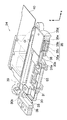
図2は、デジタルカメラ1を正姿勢(図1(a)の姿勢)で保持した場合において、撮像素子55が光軸上(光軸と略一致する位置)にある場合の像ブレ補正装置24の概略を示す図である。図2に示すように、像ブレ補正装置24は、主として、CCDケース30と、CCDプレート31と、ボイスコイルモータ32と、メインガイド軸33と、回転止めガイド軸34と、ボイスコイルモータ35と、メインガイド軸36と、回転止めガイド軸37と、スライダー38と、フレーム39と、メインフレキシブル基板40と、ボイスコイルモータ用フレキシブル基板41とで構成される。
FIG. 2 shows an image
CCDケース30は、撮像素子55を保持する樹脂製の部材である。CCDケース30の右側(+x側)上端(+y側)近傍には軸受30aが形成され、回転止めガイド軸34が挿通される。CCDケース30の左側(−x方向)には、軸受30bが2箇所形成され、軸受30bにはメインガイド軸33が挿通される。
The
CCDプレート31は、金属製の板状の部材であり、アオリ調整等に用いられる。CCDプレート31は、CCDケース30を覆うようにCCDケース30の前面側(+z側)にネジ止めされる。CCDプレート31は略中央に孔が形成され、孔からは撮像素子55が露出される。CCDプレート31の右端部には、右側の辺に沿ってリブ状の凸部31aが形成される。
The
ボイスコイルモータ32、35は、モータドライバ77(図5参照)から出力される信号に応じて駆動され、ボイスコイルモータ32は、CCDケース30及びCCDプレート31をy方向へ移動させ、ボイスコイルモータ35は、CCDケース30、CCDプレート31及びスライダー38をx方向へ移動させる。ボイスコイルモータ32、35の構造は、ボイスコイルモータ32には放熱部材35d(後の詳述)が配設されていないこと以外同一であるため、ボイスコイルモータ35について説明する。
The
図3は、図2のA−A断面である。ボイスコイルモータ35は、ヨーク35aと、コイル35bと、磁石35cと、放熱部材35dで構成される。
3 is a cross-sectional view taken along the line AA in FIG. The
ヨーク35aは、フレーム39に固着された金属の板材である。ヨーク35aは、磁石35cによる漏れ磁束を減らし、ヨーク35a間の磁界を強くするためのもので、1枚は磁石35cに隣接して配設され、他のヨーク35aは、ヨーク35aでコイル35b、磁石35cを挟むような位置に配設される。他のヨーク35aの前面側には、金属製の放熱部材35dが一体形成される。
The
磁石35cは、両面多極のマグネットであり、ヨーク35aの前面側に隣接して配設される。磁石35cは、図3中、左側(−x側)には上向き(+z方向)の磁界が発生し、右側(+x側)には下向き(−z方向)の磁界が発生する(図3矢印参照)。なお、図3に示す磁界の向きは一例であり、これに限定されない。
The
コイル35bは、CCDプレート31の端部に固着された断面略長方形の筒状の空芯コイルであり、+z方向から見て反時計回りの巻方向で光軸方向(z方向)に重ねるように形成される。なお、このコイル35bの巻方向は一例であり、これに限定されない。コイル35bは、CCDケース30の右側に形成された凸部30cに固着され、磁石35cによる磁界中に配設されている。したがって、コイル35bに電流を流すと、フレミングの左手の法則により、磁界と電流の双方に垂直方向に力が発生する。磁石35cはフレーム39に固着されているため、この力により磁石35cが磁界と電流の双方に垂直方向、すなわちx方向に移動し、それにあわせてCCDケース30及びCCDプレート31、すなわち撮像素子55もx方向に移動する。
The
図4は、図3に示す撮像素子55が光軸上にある状態からCCDケース30及びCCDプレート31が+x方向に最大限移動した後の状態である。CCDケース30及びCCDプレート31は、凸部31aが放熱部材35dに接触する位置まで移動可能である。撮像素子55で発生した熱は、CCDケース30を介してCCDプレート31に伝えられる。凸部31aと放熱部材35dとが接触していることより、CCDプレート31に伝えられた熱は放熱部材35dに伝えられ(図4矢印参照)、放熱部材35dから空気中に放熱される。
FIG. 4 shows a state after the
メインガイド軸33は、CCDケース30及びCCDプレート31をy方向に移動させるための軸であり、軸受30bに挿通され、スライダー38に固着される。回転止めガイド軸34は、CCDケース30及びCCDプレート31がメインガイド軸33を中心に回転するのを止めるものであり、貫通孔30bに挿通され、スライダー38に固着される。メインガイド軸33と回転止めガイド軸34とは、平行に、撮像素子55の両側に配設される。
The
スライダー38は、略ロの字形状の部材であり、CCDケース30及びCCDプレート31をx方向へ移動させる。スライダー38を略ロの字形状とすることにより、スライダー38の強度が保たれる。スライダー38の上側(+y方向)両端近傍には軸受38aが2箇所形成され、メインガイド軸36が挿通される。スライダー38の下側(−y方向)左端(−x方向)近傍には、軸受38bが形成され、回転止めガイド軸37が挿通される。
The
メインガイド軸36は、スライダー38をx方向に移動させるための軸であり、軸受38aに挿通され、フレーム39に固着される。軸受38aがメインガイド軸36に沿って動くことにより、スライダー38がx方向に移動する。回転止めガイド軸37は、スライダー38がメインガイド軸36を中心に回転するのを止めるものであり、軸受38bに挿通されてフレーム39に固着される。メインガイド軸36と回転止めガイド軸37は、平行に、撮像素子55の両側に配設される。
The
フレーム39は、メインガイド軸36及び回転止めガイド軸37をカメラボディ11内部に固定する部材である。
The
メインフレキシブル基板40、ボイスコイルモータ用フレキシブル基板41は、折り曲げ可能な薄型基板である。メインフレキシブル基板40は、撮像素子55へ電源を供給すると共に図示しないメイン基板と撮像素子55との間を電気的に接続する。ボイスコイルモータ用フレキシブル基板41は、ボイスコイルモータ32、35へ電源を供給すると共に図示しないメイン基板とボイスコイルモータ32、35との間を電気的に接続する。
The main
次に、デジタルカメラ1の電気的な構成について説明する。図5に示すように、デジタルカメラ1は、主として、CPU50、操作手段(シャッターボタン15、電源ボタン16、モードダイヤル17、ズームボタン19、十字ボタン20、MENU/OKボタン21、DISP/BACKボタン22、再生ボタン23等)51、SDRAM52、EEPROM53、タイミングジェネレータ(TG)54、撮像素子55、アナログ信号処理手段56、A/D変換器57、画像入力コントローラ58、画像信号処理手段59、圧縮伸張処理手段60、AE/AWB検出手段61、AF検出手段62、ビデオエンコーダ63、メディアコントローラ64、ジャイロセンサ71、74、アンプ72、75、A/D変換器73、76、モータドライバ77、位置検出素子78、79で構成される。
Next, the electrical configuration of the
CPU50は、デジタルカメラ1の全体の動作を統括制御する制御手段として機能するとともに、各種の演算処理を行う演算手段として機能し、操作手段121等からの入力に基づき所定の制御プログラムに従ってデジタルカメラ1の各部を制御する。
The
SDRAM52は、CPU50の作業用領域として利用されると共に画像データ等の一時記憶領域として利用される。
The
EEPROM53は、不揮発性メモリであり、各種制御用のプログラムや設定情報などを格納している。メインCPU50は、このプログラムや設定情報に基づいて各種処理を実行する。
The
TG54は、撮像素子55の光電荷蓄積・転送動作を制御する。TG54から入力されるタイミング信号(クロックパルス)により、電子シャッター速度(光電荷蓄積時間)が決定される。
The
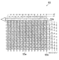
撮像素子55は、レンズ光軸上に配置されたCCD型のイメージセンサであり、ズームレンズ、フォーカスレンズ等によって結像された被写体の画像を電子的に撮像する。図6に示すように、撮像素子55の受光面には多数のフォトダイオード55aが2次元的に配列されており、受光面に入射された被写体光は、各フォトダイオード55aによって入射光量に応じた量の信号電荷に変換される。そして、各フォトダイオード55aに蓄積された信号電荷は、TG54から与えられるタイミングパルスに従って読み出され、垂直転送路55b上を図6の上方向へシフトさせて水平転送路55cへと転送され、水平転送路55c上を左方向へ転送され、アンプで電圧信号に変換されることで、信号電荷に応じた電圧信号(画像信号)として出力される。撮像素子55から出力された撮像信号は、それぞれアナログ信号処理手段56に入力される。
The
垂直転送路55bを駆動するVl〜V4に印加する電圧信号に比べ、水平転送路55cを駆動するHl、H2に印加する電圧信号の方が高周波であり消費電力が高い。したがって、撮像素子55の中で最も熱が発生するのは水平転送路55cである。本実施の形態では、CCDケース30、CCDプレート31及びスライダー38をx方向へ移動させ、ボイスコイルモータ35から放熱を行うため、撮像素子55は、最も熱が発生する水平転送路55cと放熱部材とが最短距離で接触するように、水平転送路55cが+x方向に位置するようにCCDケースの中に配設される。
Compared with the voltage signals applied to Vl to V4 that drive the
アナログ信号処理手段56は、撮像素子55から出力された画像信号に対してそれぞれ相関二重サンプリング処理(撮像素子の出力信号に含まれるノイズ(特に熱雑音)等を軽減することを目的として、撮像素子の1画素毎の出力信号に含まれるフィードスルー成分レベルと画素信号成分レベルとの差をとることにより正確な画素データを得る処理)を行い、増幅して出力する。
The analog signal processing means 56 captures each of the image signals output from the
A/D変換器57は、入力された画像データをアナログからデジタルに変換する。A/D変換器57を通して、光学系12の撮像素子55が画像データとして出力される。
The A /
画像入力コントローラ58は、所定容量のラインバッファを内蔵しており、CPU50からの指令に従い、A/D変換器57から出力された1画像分の画像信号を蓄積して、SDRAM52に記録する。
The
画像信号処理手段59は、同時化回路(単板CCDのカラーフィルタ配列に伴う色信号の空間的なズレを補間して色信号を同時式に変換する処理回路)、ホワイトバランス補正回路、ガンマ補正回路、輪郭補正回路、輝度・色差信号生成回路等を含み、CPU50からの指令に従い、A/D変換器57から入力された画像データに所要の信号処理を施して、輝度データ(Yデータ)と色差データ(Cr,Cbデータ)とからなる画像データ(YUVデータ)を生成し、表示用のビデオエンコーダ63に出力する。撮影モード時に電子ビューファインダとして使用される際には、生成された画像データが、ビデオエンコーダ63を介してモニタ18にライブビュー画像(スルー画像)として表示される。また、画像信号処理手段59は、撮像素子55により撮影された画像データ及び撮像素子55により撮影された画像データのYC信号を、所定方式の映像信号(例えば、NTSC方式のカラー複合映像信号)に変換した上で、外部の立体画像表示装置等において立体表示を行うための立体画像データに合成する。
The image signal processing means 59 is a synchronization circuit (a processing circuit that converts a color signal into a simultaneous expression by interpolating a spatial shift of the color signal associated with the color filter array of a single CCD), a white balance correction circuit, and a gamma correction. A circuit, a contour correction circuit, a luminance / color difference signal generation circuit, etc., and in accordance with a command from the
圧縮伸張処理手段60は、CPU50からの指令に従い、入力された画像データに所定形式の圧縮処理を施し、圧縮画像データを生成する。また、圧縮伸張処理手段60は、SDRAM52に記憶された画像データに対して、静止画ではJPEG、動画ではMPEG2、MPEG4、H.264方式等の所定の圧縮形式に従って圧縮処理を施す。圧縮伸張処理手段60は、静止画の2次元画像のデータをExifファイル等の所定のフォーマットの画像ファイル(画像ファイルについては後に詳述する)として記録メディア65に格納する。Exifファイルは、主画像のデータを格納する領域と、縮小画像(サムネイル画像)のデータを格納する領域とを有している。撮影によって取得された主画像のデータから画素の間引き処理その他の必要なデータ処理を経て、規定サイズ(例えば、160×120又は80×60ピクセルなど)のサムネイル画像が生成される。こうして生成されたサムネイル画像は、主画像とともにExifファイル内に書き込まれる。また、Exifファイルには、撮影日時、撮影条件、顔検出情報等のタグ情報が付属されている。
The compression /
AE/AWB検出手段61は、撮影スタンバイ状態時にレリーズスイッチが半押しされると、CPU50からの指令に従い、入力された画像信号からAE制御及びAWB制御に必要な物理量を算出する。たとえば、AE制御に必要な物理量として、1画面を複数のエリア(たとえば16×16)に分割し、分割したエリアごとにR、G、Bの画像信号の積算値を算出する。CPU50は、このAE/AWB検出手段61から得た積算値に基づいて被写体の明るさ(被写体輝度)を検出し、撮影に適した露出値(撮影EV値)を算出する。そして、算出した撮影EV値と所定のプログラム線図から絞り値とシャッター速度を決定する。
When the release switch is half-pressed in the shooting standby state, the AE /
また、AE/AWB検出手段61は、AWB制御に必要な物理量として、1画面を複数のエリア(例えば、16×16)に分割し、分割したエリアごとにR、G、Bの画像信号の色別の平均積算値を算出する。CPU50は、得られたRの積算値、Bの積算値、Gの積算値から分割エリアごとにR/G及びB/Gの比を求め、求めたR/G、B/Gの値のR/G、B/Gの色空間における分布等に基づいて光源種判別を行う。そして、判別された光源種に適したホワイトバランス調整値に従って、たとえば各比の値がおよそ1(つまり、1画面においてRGBの積算比率がR:G:B≒1:1:1)になるように、ホワイトバランス調整回路のR、G、B信号に対するゲイン値(ホワイトバランス調整値)を決定する。
The AE /
AF検出手段62は、撮影スタンバイ状態時にレリーズスイッチが半押しされると、CPU50からの指令に従い、入力された画像信号からAF制御に必要な物理量を算出する。本実施の形態のデジタルカメラ1では、撮像素子55から得られる画像のコントラストによりAF制御が行われ(いわゆるコントラストAF)、AF検出手段62は、入力された画像信号から画像の鮮鋭度を示す焦点評価値を算出する。CPU50は、このAF検出手段62で算出される焦点評価値が極大となる位置を検出し、その位置にフォーカスレンズ群を移動させる。すなわち、フォーカスレンズ群を至近から無限遠まで所定のステップで移動させ、各位置で焦点評価値を取得し、得られた焦点評価値が最大の位置を合焦位置として、その位置にフォーカスレンズ群を移動させる。
When the release switch is half-pressed in the shooting standby state, the AF detection means 62 calculates a physical quantity necessary for AF control from the input image signal in accordance with a command from the
ビデオエンコーダ63は、画像信号処理手段59から出力されたRGB信号をモニタ18に出力する。
The
メディアコントローラ64は、圧縮伸張処理手段60によって圧縮処理された各画像データを、メディアコントローラ64経由で接続された記録メディア65やその他の記録メディアに記録させる。
The
記録メディア65は、デジタルカメラ1に着脱自在なxDピクチャカード(登録商標)、スマートメディア(登録商標)に代表される半導体メモリカード、可搬型小型ハードディスク、磁気ディスク、光ディスク、光磁気ディスク等、種々の記録媒体である。
The
また、デジタルカメラ1には、電源電池が着脱可能に設けられている。電源電池は、充電可能な二次電池、例えばニカド電池、ニッケル水素電池、リチウムイオン電池で構成される。電源電池は使い切り型の一次電池、例えばリチウム電池、アルカリ電池で構成してもよい。電源電池は、図示しない電池収納室に装填することにより、デジタルカメラ1の各手段と電気的に接続される。
Further, the
ジャイロセンサ71、74は、デジタルカメラ1の角速度を検出するセンサであり、手振れによるデジタルカメラ1の振動を検出する。ジャイロセンサ71はx方向(図2参照)の加速度を検出し、ジャイロセンサ74はy方向(図2参照)の加速度を検出する。
The
アンプ72、75、は、ジャイロセンサ71、74で検出された信号をそれぞれ増幅し、A/D変換器73、76に出力する。
The
A/D変換器73、76は、アンプ72、75で増幅した信号をデジタル信号に変換し、変換した信号をCPU50に入力する。CPU50は、ジャイロセンサ71、74からそれぞれ入力された信号を増幅して、モータドライバ77に出力する。
The A /
モータドライバ77は、CPU50から入力された信号に基づいてボイスコイルモータ32、35を駆動する。
The
位置検出素子78、79は、例えばホール素子であり、CCDプレート31の位置を検出する。位置検出素子78はy方向の位置を検出し、位置検出素子79はx方向の位置を検出する。位置検出素子78は、スライダー38がy方向に移動された都度、位置検出を行い、位置検出素子79は、CCDプレート31がx方向に移動された都度、位置検出を行う。
The
このようにして構成されたデジタルカメラ1の作用について説明する。図7は、デジタルカメラ1の処理の流れを示すフローチャートである。以下の処理は、主としてCPU50で行われる。
The operation of the
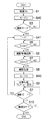
電源ボタンを押下し、デジタルカメラ1の電源を投入する(ステップS1)と、CPU50は、像ブレ補正装置24をモード2で駆動する(ステップS2)。図8(b)に示すように、ステップS2では、CPU50はコイル35bに電流を流してボイスコイルモータ35を駆動することでCCDケース30及びCCDプレート31を+x方向へ移動させ、凸部31aと放熱部材35dとを接触させる(ステップS11)。位置検出素子79はCCDプレート31の位置を検出し(ステップS12)、位置検出素子79により凸部31aと放熱部材35dとが接触したことが検出され、その検出信号がCPU50に入力されると、CPU50は、凸部31aと放熱部材35dとが接触した状態でCCDケース30及びCCDプレート31を停止させるように、コイル35bに電流を流してボイスコイルモータ35を駆動する(ステップS13)。
When the power button is pressed to turn on the digital camera 1 (step S1), the
CPU50は、デジタルカメラ1の動作モードが撮影モードであるかどうかを検出する(ステップS3)。デジタルカメラ1が撮影モードで無い場合(ステップS3でNO)には、再度ステップS3が行われる。
The
デジタルカメラ1が撮影モードである場合(ステップS3でYES)には、スルー画像の撮影と同時に像ブレ補正装置24をモード1で駆動して像ブレ補正を行う(ステップS4)。
When the
ステップS4の処理について説明する。まず、CPU50は、位置検出素子79を用いてx方向の位置を検出し、撮像素子55の中心と光軸とが一致していない場合にはコイル35bに電流を流し、撮像素子55の中心と光軸とを一致させる(ステップS14)。その後、撮像素子55で連続的に画像が撮像され、その画像信号が連続的に処理されて、スルー画像用の画像データが生成される。生成された画像データは、順次ビデオエンコーダ63に加えられ、表示用の信号形式に変換されて、それぞれモニタ18に出力される。これにより、撮像素子55によるスルー画像用の撮影が開始される。
The process of step S4 will be described. First, the
このスルー画像撮影開始以降、CPU50は、以下のようにして、デジタルカメラ1に加えられた振動(手ブレなど)による撮像素子55で撮像される被写体像の像ブレを補正する防振処理(ステップS15)を行う。
After the start of the through image shooting, the
ジャイロセンサ71、74でx方向及びy方向の振動が検出されると、検出信号がアンプ72、75、及びA/D変換器73、76を介してCPU50に入力される。CPU50は、ジャイロセンサ71から入力された信号に基づいて、モータドライバ77を介してボイスコイルモータ35を駆動させる。また、CPU50は、ジャイロセンサ74から入力された信号に基づいて、モータドライバ77を介してボイスコイルモータ32を駆動させる。位置検出素子78、79は、ボイスコイルモータ32、35が駆動されるとそれぞれy方向、x方向の位置を検出し、CPU50に結果を出力する。CPU50は、位置検出素子78、79から入力された位置が目標の位置となるように、ボイスコイルモータ32、35を制御する。これにより、適切な防振動作を行うことができる。
When vibrations in the x and y directions are detected by the
CPU50は、シャッターボタン15が半押しされたか、すなわちCPU50にS1ON信号が入力されたかを判断する(ステップS5)。S1ON信号が入力されていない場合(ステップS5でNO)には、再度ステップS5を行う。S1ON信号が入力された場合(ステップS5でYES)には、このS1ON信号に応動して、以下のような撮影準備処理、すなわち、AE、AF、AWBの各処理を実行する(ステップS6)。
The
まず、撮像素子55から取り込まれた画像信号がAF検出手段138並びにAE/AWB検出手段139に入力される。AF検出手段138で求めた積算値のデータはCPU50に通知される。
First, an image signal captured from the
CPU50は、光学系12のフォーカスレンズ群を移動させながら、複数のAF検出ポイントで焦点評価値(AF評価値)を演算し、評価値が極大となるレンズ位置を合焦位置として決定する。そして、求めた合焦位置にフォーカスレンズ群を移動させる。
The
CPU50は、AE/AWB検出手段139から得た積算値に基づいて被写体の明るさ(被写体輝度)を検出し、撮影に適した露出値(撮影EV値)を算出する。そして、求めた撮影EV値と所定のプログラム線図から絞り値とシャッタースピードを決定し、これに従い撮像素子55の電子シャッターと絞りを制御して適正な露光量を得る。同時に、検出された被写体輝度より、ストロボ14の発光が必要かどうかを判断する。
The
また、AE/AWB検出手段139は、自動ホワイトバランス調整時、分割エリアごとにR、G、B信号の色別の平均積算値を算出し、その算出結果をCPU50に提供する。CPU50は、得られたRの積算値、Bの積算値、Gの積算値から分割エリアごとにR/G及びB/Gの比を求め、求めたR/G、B/Gの値のR/G、B/Gの色空間における分布等に基づいて光源種判別を行う。そして、判別された光源種に適したホワイトバランス調整値に従って、たとえば、各比の値がおよそ1(つまり、1画面においてRGBの積算比率がR:G:B≒1:1:1)になるように、ホワイトバランス調整回路のR、G、B信号に対するゲイン値(ホワイトバランス補正値)を制御し、各色チャンネルの信号に補正をかける。
The AE / AWB detection unit 139 calculates an average integrated value for each color of the R, G, and B signals for each divided area during automatic white balance adjustment, and provides the calculation result to the
以上のように、シャッターボタン15の半押しによって、AE/AF処理が行なわれる。なお、撮影者は、必要に応じてズームボタン19を操作し、レンズ14をズーミングさせて画角を調整する。
As described above, the AE / AF process is performed by half-pressing the
CPU50は、シャッターボタン15が全押しされたか、すなわちCPU50にS2ON信号が入力されたかを判断する(ステップS7)。S2ON信号が入力されていない場合(ステップS7でNO)には、再度ステップS5が行われる。S2ON信号が入力された場合(ステップS7でYES)には、このS2ON信号に応動して、以下のような撮影処理及び記録処理(ステップS8)を実行する。
The
まず、上記のAE処理で求めた絞り値、シャッタースピードで撮像素子55を露光し、記録用の画像を撮像する。撮像素子55から出力された画像信号は、アナログ信号処理手段56、A/D変換器57、画像入力コントローラ58を介して取り込まれ、SDRAM52に格納される。SDRAM52に格納された画像信号は、CPU50の制御の下、画像信号処理手段59に加えられる。画像信号処理手段59は、入力された画像信号に所定の信号処理を施して、輝度データと色差データとからなる画像データ(YUVデータ)を生成する。
First, the
画像信号処理手段59で生成された画像データは、一旦SDRAM52に格納されたのち、メディアコントローラ64に加えられる。メディアコントローラ64は、入力された画像データに対して所定の圧縮処理を施し、圧縮画像データを生成する。
The image data generated by the image signal processing means 59 is temporarily stored in the
圧縮された画像データは、SDRAM52に格納され、所定フォーマットの静止画像ファイル(たとえば、Exif)として、メディアコントローラ64を介して記録メディア65に記録される。
The compressed image data is stored in the
このようにして撮影処理及び記憶処理(ステップS8)が行われると、CPU50は、像ブレ補正装置24をモード2で駆動する(ステップS2)。これにより、CCDプレート31の凸部31aが放熱部材35dに接触し、撮影準備処理(ステップS7)、撮影処理(ステップS8)において撮像素子55で発生した熱が放熱部材35dから放熱される。
When the photographing process and the storage process (step S8) are performed in this way, the
CPU50は、ステップS8で生成された圧縮画像データを圧縮伸張処理手段60に加え、非圧縮の画像データとしたのちSDRAM52に加え、SDRAM52からビデオエンコーダ63を介してモニタ18に出力することによりプレビュー表示を行う(ステップS9)。プレビュー表示(ステップS9)が行われている間も、像ブレ補正装置24はモード2で駆動されており、放熱が継続して行われる。
The
CPU50は、デジタルカメラ1の動作モードが撮影モードであるかどうかを検出する(ステップS3)。デジタルカメラ1が撮影モードである場合(ステップS3でYES)には、スルー画像の撮影と同時に像ブレ補正装置24をモード1で駆動して像ブレ補正を行う(ステップS4)。このように継続して撮影を行う場合においても、直前まで像ブレ補正装置24がモード2で駆動されている(ステップS2)ため、撮像素子55の温度上昇を抑えることができ、熱により画像のノイズを低減することができる。
The
デジタルカメラ1が撮影モードで無い場合(ステップS3でNO)には、電源がOFFされたかが判断される(ステップS10)。電源がOFFされていない場合(ステップS10でNO)には、再度ステップS3が行われ、電源がOFFされた場合(ステップS3でYES)には処理が終了される。
If the
プレビュー表示(ステップS9)以外でも、ステップS8で撮影した画像の確認が可能である。再生ボタン23が押下されると、CPU50は、デジタルカメラ1を再生モードに切り替える。CPU50は最後に記録された画像ファイルの圧縮画像データを読み出す。最後に記録された画像ファイルが記録メディア65に記録されている場合には、CPU50は、メディアコントローラ64を介して記録メディア65に最後に記録された画像ファイルの圧縮画像データを読み出す。
In addition to the preview display (step S9), it is possible to check the image taken in step S8. When the
記録メディア65から読み出された圧縮画像データは、圧縮伸張処理手段60に加えられ、非圧縮の画像データとされたのちSDRAM52に加えられる。そして、SDRAM52からビデオエンコーダ63を介してモニタ18に出力される。これにより、記録メディア65又はフラッシュROM114に記録されている画像が、モニタ18に再生表示される。この処理の間も像ブレ補正装置24がモード2で駆動されている(ステップS2)ため、撮像素子55の温度上昇を抑えることができる。
The compressed image data read from the
本実施の形態によれば、新たな部品が必要ないうえ、駆動対象物に負荷が加えられないため、像ブレ補正時の駆動物の質量増加が無いため、防振性能の劣化がなく、かつ撮像素子で発生する熱を効率よく放熱することができる。 According to the present embodiment, since no new parts are required and no load is applied to the driven object, there is no increase in the mass of the driven object at the time of image blur correction, there is no deterioration in the vibration proof performance, and Heat generated by the image sensor can be efficiently radiated.
また、本実施の形態では、撮影後のプレビュー表示が行われている時に防振処理をOFFし、CCDプレートと放熱部材とを接触させるようにしたため、効率よく放熱することができる。したがって、連続撮影時等に撮像素子の温度上昇を防止し、ノイズを低減させることができる。 In this embodiment, since the image stabilization process is turned off and the CCD plate and the heat radiating member are brought into contact with each other when the preview display after photographing is performed, heat can be efficiently radiated. Therefore, the temperature of the image sensor can be prevented from increasing during continuous shooting, and noise can be reduced.
なお、本実施の形態では、放熱部材35dから空気中へ放熱したが、放熱部材35dとカメラボディ11とを直接又は伝熱部材を介して接触させ、カメラボディ11から外部へ放熱するようにしてもよい。この場合は、カメラボディ11を金属材料、セラミック等の熱伝導性の高い伝熱性材料で形成することが望ましい。カメラボディ11はサイズが大きいため、熱容量も大きい。したがって、撮像素子で発生した熱をより効率的に放熱することができる。
In the present embodiment, heat is radiated from the
また、本実施の形態では、モード2(ステップS2)において、位置検出素子79はCCDプレート31の位置を検出し(ステップS12)、位置検出素子79により凸部31aと放熱部材35dとが接触したことが検出され、凸部31aと放熱部材35dとが接触した状態でCCDケース30及びCCDプレート31を停止させた(ステップS13)が、デジタルカメラ1に衝撃等が加わることにより凸部31aと放熱部材35dとが離れてしまう虞がある。そのため、図9に示すように、凸部31aと放熱部材35dとが接触した状態でCCDケース30及びCCDプレート31を停止させた(ステップS13)後で、位置検出素子79により凸部31aと放熱部材35dとの接触がはずれたか否かを検出し(ステップS15)、凸部31aと放熱部材35dとの接触がはずれたことが検出された(ステップS15でYES)場合にはCCDケース30及びCCDプレート31を+x方向へ移動させ、凸部31aと放熱部材35dとを接触させる(ステップS11)ようにしてもよい。
In the present embodiment, in mode 2 (step S2), the
また、本実施の形態では、撮像素子55としてCCD型のイメージセンサを用いたが、CMOS型のイメージセンサでもよい。CMOS型のセンサの場合には、搭載されたチップの位置等により最も発熱する位置が異なるため、そのCMOS型のセンサのうち最も発熱しやすいところを放熱部材に一番近いところ(本実施の形態では+x側)に配設するのが望ましい。
In this embodiment, a CCD type image sensor is used as the
また、本実施の形態では、像ブレ補正装置のアクチュエーターとしてボイスコイルモータを用いたが、ボイスコイルモータに限定されない。例えば、ステッピングモータや圧電素子等を用いた伸縮型のアクチュエーター等を用いることもできる。 In this embodiment, the voice coil motor is used as the actuator of the image blur correction apparatus, but the present invention is not limited to the voice coil motor. For example, a telescopic actuator using a stepping motor or a piezoelectric element can be used.
<第2の実施の形態>
本発明の第1の実施の形態は、モード2において、像ブレ補正装置24を駆動してCCDプレート31の凸部31aと放熱部材35dとを接触させて放熱を行ったが、凸部31aと放熱部材35dとを接触状態で保持するためには、ボイスコイルモータ35のコイル35bに電流を流し続ける必要がある。コイル35bで電力を消費するためコイル35bで熱が発生するが、放熱のために発熱が行われることとなり効率が悪い。
<Second Embodiment>
In the first embodiment of the present invention, in
第2の実施の形態は、弾性部材を用いてCCDプレート31の凸部31aと放熱部材35dとを接触させる形態である。以下、第2の実施の形態に係るデジタルカメラ2について説明する。なお、第1の実施の形態と同一の部分については、同一の符号を付し、説明を省略する。
In the second embodiment, the
デジタルカメラ2のカメラボディ11は、横長の四角い箱状に形成されており、その正面には、光学系12A、ストロボ14等が配設されている。また、カメラボディ11の上面にはシャッターボタン15、電源ボタン16、モードダイヤル17等が配設されている。一方、カメラボディ11の背面には、モニタ18、ズームボタン19、十字ボタン20、MENU/OKボタン21、DISP/BACKボタン22、再生ボタン23等が配設されている。
The
次に、光学系12Aの詳細について説明する。光学系12Aは、主として、絞り、フォーカスレンズ、ズームレンズ(以上、図示せず)、像ブレ補正装置25で構成される。
Next, details of the optical system 12A will be described. The optical system 12A is mainly composed of a diaphragm, a focus lens, a zoom lens (not shown), and an image
像ブレ補正装置25は、ジャイロセンサ71、74(図5参照)によりデジタルカメラ1の振れを検出し、撮像素子55(図5参照)をデジタルカメラ1の振れと反対方向に移動させることにより、撮像素子55に結像される被写体像の像ブレを補正する。
The image
図10は、像ブレ補正装置25の横断面図である。像ブレ補正装置25は、主として、CCDケース30と、CCDプレート31と、ボイスコイルモータ32と、メインガイド軸33と、回転止めガイド軸34と、ボイスコイルモータ35と、メインガイド軸36と、回転止めガイド軸37と、スライダー38と、フレーム39と、メインフレキシブル基板40と、ボイスコイルモータ用フレキシブル基板41と、バネ42とで構成される。
FIG. 10 is a cross-sectional view of the image
バネ42は、図10に示すように、CCDプレート31とフレーム39との間に配設される。バネ42は、CCDプレート31に+x方向の付勢力を付勢する。そのため、ボイスコイルモータ35のコイル35bに電流を流さない場合には、図9(b)に示すように、凸部31aと放熱部材35dとが接触した状態となる。防振処理を行う場合には、ボイスコイルモータ35のコイル35bに電流を流し、図9(a)に示すように凸部31aと放熱部材35dとを離す。この場合には、バネ42は、メインガイド軸33と軸受30bとの間に生ずるメカのガタ部を抑えるために用いられる。
As shown in FIG. 10, the
このようにして構成されたデジタルカメラ2の作用について説明する。図11は、デジタルカメラ1の処理の流れを示すフローチャートである。以下の処理は、主としてCPU50で行われる。
The operation of the
電源ボタンを押下し、デジタルカメラ1の電源を投入する(ステップS1)と、CPU50は、像ブレ補正装置25をモード2で駆動する(ステップS20)。図12(b)に示すように、ステップS20では、CPU50はコイル35bに電流を流さないようにすると、バネ42の付勢力でCCDケース30及びCCDプレート31が+x方向へ移動され、凸部31aと放熱部材35dとが接触される(ステップS22)。
When the power button is pressed to turn on the digital camera 1 (step S1), the
CPU50は、デジタルカメラ1の動作モードが撮影モードであるかどうかを検出する(ステップS3)。デジタルカメラ1が撮影モードで無い場合(ステップS3でNO)には、再度ステップS3が行われる。
The
デジタルカメラ1が撮影モードである場合(ステップS3でYES)には、スルー画像の撮影と同時に像ブレ補正装置25をモード1で駆動して像ブレ補正を行う(ステップS21)。
When the
ステップS21の処理について説明する。まず、CPU50は、コイル35bに電流を流し、CCDケース30及びCCDプレート31をバネ42の付勢力に抗して−x方向へ移動させ、撮像素子55の中心と光軸とを一致させる(ステップ23)。その状態で、撮像素子55で連続的に画像が撮像され、その画像信号が連続的に処理されて、スルー画像用の画像データが生成される。生成された画像データは、順次ビデオエンコーダ63に加えられ、表示用の信号形式に変換されて、それぞれモニタ18に出力される。これにより、撮像素子55によるスルー画像用の撮影が開始される。
The process of step S21 will be described. First, the
このスルー画像撮影開始以降、CPU50は、デジタルカメラ1に加えられた振動(手ブレなど)による撮像素子55で撮像される被写体像の像ブレを補正する防振処理(ステップS15)を行う。
After starting the through image shooting, the
CPU50は、シャッターボタン15が半押しされたか、すなわちCPU50にS1ON信号が入力されたかを判断する(ステップS5)。S1ON信号が入力されていない場合(ステップS5でNO)には、再度ステップS5を行う。S1ON信号が入力された場合(ステップS5でYES)には、このS1ON信号に応動して撮影準備処理、すなわち、AE、AF、AWBの各処理を実行する(ステップS6)。
The
CPU50は、シャッターボタン15が全押しされたか、すなわちCPU50にS2ON信号が入力されたかを判断する(ステップS7)。S2ON信号が入力されていない場合(ステップS7でNO)には、再度ステップS5が行われる。S2ON信号が入力された場合(ステップS7でYES)には、このS2ON信号に応動して撮影処理及び記録処理(ステップS8)を実行する。
The
撮影処理及び記憶処理(ステップS8)が行われると、CPU50は、像ブレ補正装置25をモード2で駆動する(ステップS20)。これにより、CCDプレート31の凸部31aが放熱部材35dに接触し、撮影準備処理(ステップS7)、撮影処理(ステップS8)において撮像素子55で発生した熱が放熱部材35dから放熱される。
When the photographing process and the storage process (step S8) are performed, the
CPU50は、ステップS8で生成された圧縮画像データを圧縮伸張処理手段60に加え、非圧縮の画像データとしたのちSDRAM52に加え、SDRAM52からビデオエンコーダ63を介してモニタ18に出力することによりプレビュー表示を行う(ステップS9)。プレビュー表示(ステップS9)が行われている間も、像ブレ補正装置25はモード2で駆動されており、放熱が継続して行われる。
The
CPU50は、デジタルカメラ1の動作モードが撮影モードであるかどうかを検出する(ステップS3)。デジタルカメラ1が撮影モードである場合(ステップS3でYES)には、スルー画像の撮影と同時に像ブレ補正装置25をモード1で駆動して像ブレ補正を行う(ステップS21)。
The
デジタルカメラ1が撮影モードで無い場合(ステップS3でNO)には、電源がOFFされたかが判断される(ステップS10)。電源がOFFされていない場合(ステップS10でNO)には、再度ステップS3が行われ、電源がOFFされた場合(ステップS3でYES)には処理が終了される。
If the
本実施の形態によれば、像ブレ補正装置25がモード1で駆動されていない場合は、電源がOFFの場合を含めて常に凸部31aと放熱部材35dとが常時接触する。そのため、凸部31aと放熱部材35dとを接触状態に保持する時に電力を消費しない。したがって、撮像素子で発生した熱を更に効率よく放熱することができる。また、放熱を行う際にボイスコイルモータを駆動させなくてよいため、余分な熱が発生することも無い。
According to the present embodiment, when the image
また、本実施の形態によれば、電源がOFFの状態では、CCDプレート31に付勢力が働くため、CCDプレート31が振動しない。したがって、デジタルカメラの持ち運びや振動等によりCCDプレート31や放熱部材35dが破損し、ゴミが発生する等の問題を防ぐことができる。
Further, according to the present embodiment, when the power is OFF, the urging force is applied to the
なお、本実施の形態では、モード2においてコイル35bに電流を流さないことによりバネ42の付勢力で凸部31aと放熱部材35dとを接触させたが、バネの付勢力のバラツキ等により確実に接触しない可能性もある。そのため、位置検出素子79を用いてCCDケース30及びCCDプレート31の位置を検出し、凸部31aと放熱部材35dとが接触していない場合にはコイル35bに電流を流すことにより凸部31aと放熱部材35dとを接触させるようにしてもよい。
In the present embodiment, the current is not passed through the
<第3の実施の形態>
本発明の第1の実施の形態は、モード2において、像ブレ補正装置24を駆動してCCDプレート31の凸部31aと放熱部材35dとを接触させて放熱を行ったが、凸部31a、放熱部材35dのいずれも金属部材であるため、表面の凹凸や部材の傾き等により、微小な面積でしか接触せず、伝熱効率が低下する虞がある。
<Third Embodiment>
In the first embodiment of the present invention, in the
第3の実施の形態は、凸部31aと放熱部材35dとを伝熱性弾性部材を介して接触させる形態である。以下、第3の実施の形態に係るデジタルカメラ3について説明する。なお、第1の実施の形態と同一の部分については、同一の符号を付し、説明を省略する。
In the third embodiment, the
デジタルカメラ3のカメラボディ11は、横長の四角い箱状に形成されており、その正面には、光学系12B、ストロボ14等が配設されている。また、カメラボディ11の上面にはシャッターボタン15、電源ボタン16、モードダイヤル17等が配設されている。一方、カメラボディ11の背面には、モニタ18、ズームボタン19、十字ボタン20、MENU/OKボタン21、DISP/BACKボタン22、再生ボタン23等が配設されている。
The
次に、光学系12Bの詳細について説明する。光学系12Bは、主として、絞り、フォーカスレンズ、ズームレンズ(以上、図示せず)、像ブレ補正装置26で構成される。
Next, details of the optical system 12B will be described. The optical system 12B mainly includes a diaphragm, a focus lens, a zoom lens (not shown), and an image
像ブレ補正装置26は、ジャイロセンサ71、74(図5参照)によりデジタルカメラ1の振れを検出し、撮像素子55(図5参照)をデジタルカメラ1の振れと反対方向に移動させることにより、撮像素子55に結像される被写体像の像ブレを補正する。
The image
図13は、像ブレ補正装置26の横断面図である。像ブレ補正装置26は、主として、CCDケース30と、CCDプレート31と、ボイスコイルモータ32と、メインガイド軸33と、回転止めガイド軸34と、ボイスコイルモータ35と、メインガイド軸36と、回転止めガイド軸37と、スライダー38と、フレーム39と、メインフレキシブル基板40と、ボイスコイルモータ用フレキシブル基板41と、放熱用ジェル部材43とで構成される。
FIG. 13 is a cross-sectional view of the image
放熱用ジェル部材43は、シリコン等の弾力性のあるジェル状の伝熱部材であり、図13(a)、(b)に示すように、放熱部材35dのCCDプレート31側の端部に配設される。放熱用ジェル部材43は、熱伝導率が1W/m・K以上の材質のものを用いるのが望ましい。
The heat-dissipating
このようにして構成されたデジタルカメラ3の作用について説明する。図14は、デジタルカメラ1の処理の流れを示すフローチャートである。以下の処理は、主としてCPU50で行われる。
The operation of the
電源ボタンを押下し、デジタルカメラ1の電源を投入する(ステップS1)と、CPU50は、像ブレ補正装置26をモード2で駆動する(ステップS2)。これにより、図13(b)に示すように、凸部31aと放熱部材35dが放熱用ジェル部材43を介して接触するため、接触面積が増加する。したがって、より効率よく放熱することができる。
When the power button is pressed to turn on the digital camera 1 (step S1), the
CPU50は、デジタルカメラ1の動作モードが撮影モードであるかどうかを検出する(ステップS3)。デジタルカメラ1が撮影モードで無い場合(ステップS3でNO)には、再度ステップS3が行われる。
The
デジタルカメラ1が撮影モードである場合(ステップS3でYES)には、スルー画像の撮影と同時に像ブレ補正装置26をモード1で駆動して像ブレ補正を行う(ステップS30)。
When the
ステップS30の処理について図15を用いて説明する。本実施の形態では、凸部31aと放熱部材35dが放熱用ジェル部材43を介して接触しているため、放熱用ジェル部材43の粘着力により凸部31aと放熱用ジェル部材43とが張り付いてしまい、像ブレ補正装置26の防振駆動時に凸部31aと放熱用ジェル部材43と外れないために防振駆動が不可能となる、撮像素子55の端での撮影のとなり周辺光量落ちやケラレ等が発生する危険がある。そこで、凸部31aと放熱用ジェル部材43とが張り付いていた場合にも凸部31aと放熱用ジェル部材43とを確実に離すことができるように、ボイスコイルモータ35に通常以上の大きな駆動力を与え、接触からの脱出させる必要がある。そのため、CPU50は、コイル35bに流すことができる最大の電流をコイル35bに流し、CCDケース30及びCCDプレート31を−x方向へ移動させる(ステップS31)。
The process of step S30 will be described with reference to FIG. In the present embodiment, since the
そして、CPU50は、位置検出素子79を用いてx方向の位置を検出し、凸部31aと放熱用ジェル部材43とが離れたことを確認する(ステップS32)。凸部31aと放熱用ジェル部材43とが離れたことが確認できなかった場合(ステップS32でNO)には、再度ステップS31を行う。
Then, the
凸部31aと放熱用ジェル部材43とが離れたことが確認できた場合(ステップS32でNO)には、CPU50は、コイル35bに電流を流し、撮像素子55の中心と光軸とを一致させる(ステップS33)。その状態で、撮像素子55で連続的に画像が撮像され、その画像信号が連続的に処理されて、スルー画像用の画像データが生成される。生成された画像データは、順次ビデオエンコーダ63に加えられ、表示用の信号形式に変換されて、それぞれモニタ18に出力される。これにより、撮像素子55によるスルー画像用の撮影が開始される。
If it can be confirmed that the
このスルー画像撮影開始以降、CPU50は、デジタルカメラ1に加えられた振動(手ブレなど)による撮像素子55で撮像される被写体像の像ブレを補正する防振処理(ステップS15)を行う。
After starting the through image shooting, the
CPU50は、シャッターボタン15が半押しされたか、すなわちCPU50にS1ON信号が入力されたかを判断する(ステップS5)。S1ON信号が入力されていない場合(ステップS5でNO)には、再度ステップS5を行う。S1ON信号が入力された場合(ステップS5でYES)には、このS1ON信号に応動して撮影準備処理、すなわち、AE、AF、AWBの各処理を実行する(ステップS6)。
The
CPU50は、シャッターボタン15が全押しされたか、すなわちCPU50にS2ON信号が入力されたかを判断する(ステップS7)。S2ON信号が入力されていない場合(ステップS7でNO)には、再度ステップS5が行われる。S2ON信号が入力された場合(ステップS7でYES)には、このS2ON信号に応動して撮影処理及び記録処理(ステップS8)を実行する。
The
撮影処理及び記憶処理(ステップS8)が行われると、CPU50は、像ブレ補正装置25をモード2で駆動する(ステップS2)。これにより、CCDプレート31の凸部31aが放熱用ジェル部材43放熱部材35dに接触し、撮影準備処理(ステップS7)、撮影処理(ステップS8)において撮像素子55で発生した熱が放熱部材35dから放熱される。
When the photographing process and the storage process (step S8) are performed, the
CPU50は、ステップS8で生成された圧縮画像データを圧縮伸張処理手段60に加え、非圧縮の画像データとしたのちSDRAM52に加え、SDRAM52からビデオエンコーダ63を介してモニタ18に出力することによりプレビュー表示を行う(ステップS9)。プレビュー表示(ステップS9)が行われている間も、像ブレ補正装置25はモード2で駆動されており、放熱が継続して行われる。
The
CPU50は、デジタルカメラ1の動作モードが撮影モードであるかどうかを検出する(ステップS3)。デジタルカメラ1が撮影モードである場合(ステップS3でYES)には、スルー画像の撮影と同時に像ブレ補正装置25をモード1で駆動して像ブレ補正を行う(ステップS30)。
The
デジタルカメラ1が撮影モードで無い場合(ステップS3でNO)には、電源がOFFされたかが判断される(ステップS10)。電源がOFFされていない場合(ステップS10でNO)には、再度ステップS3が行われ、電源がOFFされた場合(ステップS3でYES)には処理が終了される。
If the
本実施の形態によれば、凸部31aと放熱部材35dが放熱用ジェル部材43を介して接触するため、接触面積が増加する。したがって、より効率よく放熱することができる。
According to this Embodiment, since the
なお、本実施の形態では、放熱部材に放熱用ジェル部材を配設したが、CCDプレートに放熱用ジェル部材を配設してもよいし、放熱部材、CCDプレートの両方に放熱用ジェル部材を配設してもよい。 In this embodiment, the heat radiating gel member is disposed on the heat radiating member. However, the heat radiating gel member may be disposed on the CCD plate, or the heat radiating gel member may be disposed on both the heat radiating member and the CCD plate. It may be arranged.
なお、本実施の形態では、放熱部材35dをヨーク35aと別に設けたが、放熱部材をヨーク、磁石等の金属部品と兼用させてもよい。図16は、ヨーク35aを放熱部材としても使用し、放熱用ジェル部材44をヨーク35aのCCDプレート31側の端部に配設した形態である。
In the present embodiment, the
ボイスコイルモータの場合には、磁石、ヨークは金属部材であり、熱の吸収が大きい。これらの金属部材が放熱部材を兼ねることで、放熱用に専用の部材を設ける必要がない。すなわち、放熱対策が無い場合の像ブレ補正装置の構造と差がない。したがって、サイズアップ、コストアップもなしに効率のよい放熱を行うことができる。 In the case of a voice coil motor, the magnet and the yoke are metal members and absorb a large amount of heat. Since these metal members also serve as heat dissipation members, there is no need to provide a dedicated member for heat dissipation. That is, there is no difference from the structure of the image blur correction apparatus when there is no heat dissipation measure. Therefore, efficient heat dissipation can be performed without increasing the size and cost.
また、磁石、ヨーク部材はフレーム39に固定されているが、フレーム39はカメラボディ11(もしくはレンズ鏡筒)に固定されているため、撮像素子から発生した熱をフレーム39を介してカメラボディ11に逃がすことができる。したがって、撮像素子から発生した熱を外部に逃がすことができるため、放熱効果が大きい。この場合には、カメラボディ11(もしくはレンズ鏡筒)を金属等の伝熱性材料にすることが望ましい。
Further, although the magnet and the yoke member are fixed to the
また、本実施の形態では、ボイスコイルモータ35を駆動することにより、凸部31aと放熱部材35dとが放熱用ジェル部材43を介して接触したが、図17に示すように、更に圧電素子、ボイスコイルモータ、ステッピングモータ等のアクチュエーターを用いて放熱部材35dを移動させることにより、凸部31aと放熱部材35dとを放熱用ジェル部材43を介して接触させるようにしてもよい。これにより、駆動方向の両方から凸部31aと放熱部材35dとを放熱用ジェル部材43を介して押し付けることが出来るので、放熱面積を増やすことができ、効率よく放熱することが出来る。
Further, in the present embodiment, by driving the
また、本実施の形態では、放熱用ジェル部材43を介して接触しているため、ボイスコイルモータ35に通常以上の大きな駆動力を与えてCCDケース30及びCCDプレート31を−x方向へ移動させたが、放熱用ジェル部材43を介していない実施の形態においても同様の処理を行なってもよい。
In this embodiment, since the contact is made through the heat radiating
<第4の実施の形態>
本発明の第1の実施の形態は、ボイスコイルモータ35に設けられた放熱部材35dを介して撮像素子55で発生した熱を放熱したが、撮像素子55で発生した熱を放熱する放熱部材を設ける部材はボイスコイルモータ35に限られない。また、本発明の第2の実施の形態では、弾性部材を用いてCCDプレート31の凸部31aと放熱部材35dとを接触させたが、バネカに打ち勝つための推力を得るためにコイル35bに流す電流を増やさなくてはならないため、効果的ではない。
<Fourth embodiment>
In the first embodiment of the present invention, the heat generated in the
第4の実施の形態は、ボイスコイルモータ32に設けられた放熱部材を介して撮像素子55で発生した熱を放熱する形態である。以下、第4の実施の形態に係るデジタルカメラ4について説明する。なお、第1の実施の形態と同一の部分については、同一の符号を付し、説明を省略する。
In the fourth embodiment, heat generated by the
デジタルカメラ4のカメラボディ11は、横長の四角い箱状に形成されており、その正面には、光学系12C、ストロボ14等が配設されている。また、カメラボディ11の上面にはシャッターボタン15、電源ボタン16、モードダイヤル17等が配設されている。一方、カメラボディ11の背面には、モニタ18、ズームボタン19、十字ボタン20、MENU/OKボタン21、DISP/BACKボタン22、再生ボタン23等が配設されている。
The
次に、光学系12Cの詳細について説明する。光学系12Cは、主として、絞り、フォーカスレンズ、ズームレンズ(以上、図示せず)、像ブレ補正装置27で構成される。
Next, details of the optical system 12C will be described. The optical system 12C mainly includes a diaphragm, a focus lens, a zoom lens (not shown), and an image
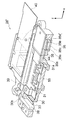
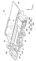
図18は、デジタルカメラ1を正姿勢(図1(a)の姿勢)で保持した場合における像ブレ補正装置27の正面斜視図である。像ブレ補正装置27は、ジャイロセンサ71、74(図5参照)によりデジタルカメラ1の振れを検出し、撮像素子55(図5参照)をデジタルカメラ1の振れと反対方向に移動させることにより、撮像素子55に結像される被写体像の像ブレを補正する。
FIG. 18 is a front perspective view of the image
CCDプレート31Aは、金属製の板状の部材であり、アオリ調整等に用いられる。CCDプレート31Aは、CCDケース30を覆うようにCCDケース30の前面側(+z側)にネジ止めされる。CCDプレート31は略中央に孔が形成され、孔からは撮像素子55が露出される。CCDプレート31Aには、鉛直下側(−y側)の辺に沿ってリブ状の凸部31bが形成される。
The
ボイスコイルモータ32A、35Aは、モータドライバ77(図5参照)から出力される信号に応じて駆動され、ボイスコイルモータ32Aは、CCDケース30及びCCDプレート31の鉛直下側に設けられ、CCDケース30及びCCDプレート31をy方向へ移動させる。ボイスコイルモータ35Aは、CCDケース30及びCCDプレート31の右側に設けられ、CCDケース30、CCDプレート31及びスライダー38をx方向へ移動させる。ボイスコイルモータ32A、35Aの構造は、ボイスコイルモータ32Aには放熱部材32d(後の詳述)が配設されていないこと以外同一であるため、ボイスコイルモータ32Aについて説明する。
The
図19は、図18のB−B断面図である。ボイスコイルモータ32Aは、ヨーク32aと、コイル32bと、磁石32cと、放熱部材32dで構成される。
19 is a cross-sectional view taken along the line BB in FIG. The
ヨーク32aは、フレーム39に固着された金属の板材である。ヨーク32aは、磁石32cによる漏れ磁束を減らし、ヨーク32a間の磁界を強くするためのもので、1枚は磁石32cに隣接して配設され、他のヨーク32aは、ヨーク32aでコイル32b、磁石32cを挟むような位置に配設される。他のヨーク32aの前面側には、金属製の放熱部材32dが一体形成される。
The
磁石32cは、両面多極のマグネットであり、ヨーク32aの前面側に隣接して配設される。磁石32cは、図19中、下側(−y側)には上向き(+z方向)の磁界が発生し、上側(+y側)には下向き(−z方向)の磁界が発生する。なお、図3に示す磁界の向きは一例であり、これに限定されない。
The
コイル32bは、CCDプレート31の端部に固着された断面略長方形の筒状の空芯コイルであり、+z方向から見て反時計回りの巻方向で光軸方向(z方向)に重ねるように形成される。なお、このコイル32bの巻方向は一例であり、これに限定されない。コイル32bは、CCDケース30の右側に形成された凸部に固着され、磁石32cによる磁界中に配設されている。したがって、コイル32bに電流を流すと、フレミングの左手の法則により、磁界と電流の双方に垂直方向に力が発生する。磁石32cはフレーム39に固着されているため、この力により磁石32cが磁界と電流の双方に垂直方向、すなわちy方向に移動し、それにあわせてCCDケース30及びCCDプレート31、すなわち撮像素子55もy方向に移動する。
The coil 32b is a cylindrical air core coil having a substantially rectangular cross section fixed to the end of the
図20は、図19に示す撮像素子55が光軸上にある状態からCCDケース30及びCCDプレート31が−y方向に最大限移動した後の状態である。CCDケース30及びCCDプレート31は、重力により、凸部31aが放熱部材32dに接触する位置まで−y方向に移動可能である。撮像素子55で発生した熱は、CCDケース30を介してCCDプレート31に伝えられる。凸部31aと放熱部材32dとが接触していることより、CCDプレート31に伝えられた熱は放熱部材32dに伝えられ(図20矢印参照)、放熱部材32dから空気中に放熱される。
FIG. 20 shows a state after the
このようにして構成されたデジタルカメラ4の作用について説明する。図21は、デジタルカメラ4の処理の流れを示すフローチャートである。以下の処理は、主としてCPU50で行われる。
The operation of the digital camera 4 configured in this way will be described. FIG. 21 is a flowchart showing a process flow of the digital camera 4. The following processing is mainly performed by the
電源ボタンを押下し、デジタルカメラ1の電源を投入する(ステップS1)と、CPU50は、像ブレ補正装置24をモード2で駆動する(ステップS40)。本実施の形態では、図22(b)に示すように、コイル32bに電流を流さない場合には、CCDケース30及びCCDプレート31が重力により−y方向へ移動している。そのため、CPU50は、位置検出素子78を用いてCCDプレート31の位置を検出し(ステップS12)、位置検出素子79により凸部31aと放熱部材32dとが接触したことが検出され、その検出信号がCPU50に入力されると、CPU50は、凸部31aと放熱部材32dとが接触した状態でCCDケース30及びCCDプレート31を停止させるように、コイル32bに電流を流してボイスコイルモータ32Aを駆動する(ステップS13)。
When the power button is pressed to turn on the digital camera 1 (step S1), the
CPU50は、デジタルカメラ1の動作モードが撮影モードであるかどうかを検出する(ステップS3)。デジタルカメラ1が撮影モードで無い場合(ステップS3でNO)には、再度ステップS3が行われる。
The
デジタルカメラ1が撮影モードである場合(ステップS3でYES)には、スルー画像の撮影と同時に像ブレ補正装置24をモード1で駆動して像ブレ補正を行う(ステップS41)。
When the
ステップS41の処理について説明する。まず、CPU50は、位置検出素子78を用いてy方向の位置を検出し、撮像素子55の中心と光軸とが一致していない場合にはコイル32bに電流を流し、撮像素子55の中心と光軸とを一致させる(ステップS42)。その後、撮像素子55で連続的に画像が撮像され、その画像信号が連続的に処理されて、スルー画像用の画像データが生成される。生成された画像データは、順次ビデオエンコーダ63に加えられ、表示用の信号形式に変換されて、それぞれモニタ18に出力される。これにより、撮像素子55によるスルー画像用の撮影が開始される。
The process of step S41 will be described. First, the
このスルー画像撮影開始以降、CPU50は、デジタルカメラ1に加えられた振動(手ブレなど)による撮像素子55で撮像される被写体像の像ブレを補正する防振処理(ステップS15)を行う。
After starting the through image shooting, the
CPU50は、シャッターボタン15が半押しされたか、すなわちCPU50にS1ON信号が入力されたかを判断する(ステップS5)。S1ON信号が入力されていない場合(ステップS5でNO)には、再度ステップS5を行う。S1ON信号が入力された場合(ステップS5でYES)には、このS1ON信号に応動して撮影準備処理、すなわち、AE、AF、AWBの各処理を実行する(ステップS6)。撮影者は、必要に応じてズームボタン19を操作し、レンズをズーミングさせて画角を調整する。
The
CPU50は、シャッターボタン15が全押しされたか、すなわちCPU50にS2ON信号が入力されたかを判断する(ステップS7)。S2ON信号が入力されていない場合(ステップS7でNO)には、再度ステップS5が行われる。S2ON信号が入力された場合(ステップS7でYES)には、このS2ON信号に応動して撮影処理及び記録処理(ステップS8)を実行する。
The
このようにして撮影処理及び記憶処理(ステップS8)が行われると、CPU50は、像ブレ補正装置24をモード2で駆動する(ステップS40)。これにより、CCDプレート31の凸部31aが放熱部材32dに接触し、撮影準備処理(ステップS7)、撮影処理(ステップS8)において撮像素子55で発生した熱が放熱部材32dから放熱される。
When the photographing process and the storage process (step S8) are performed in this way, the
CPU50は、ステップS8で生成された圧縮画像データを圧縮伸張処理手段60に加え、非圧縮の画像データとしたのちSDRAM52に加え、SDRAM52からビデオエンコーダ63を介してモニタ18に出力することによりプレビュー表示を行う(ステップS9)。プレビュー表示(ステップS9)が行われている間も、像ブレ補正装置24はモード2で駆動されており、放熱が継続して行われる。
The
CPU50は、デジタルカメラ1の動作モードが撮影モードであるかどうかを検出する(ステップS3)。デジタルカメラ1が撮影モードである場合(ステップS3でYES)には、スルー画像の撮影と同時に像ブレ補正装置24をモード1で駆動して像ブレ補正を行う(ステップS41)。このように継続して撮影を行う場合においても、直前まで像ブレ補正装置24がモード2で駆動されている(ステップS40)ため、撮像素子55の温度上昇を抑えることができ、熱により画像のノイズを低減することができる。
The
デジタルカメラ1が撮影モードで無い場合(ステップS3でNO)には、電源がOFFされたかが判断される(ステップS10)。電源がOFFされていない場合(ステップS10でNO)には、再度ステップS3が行われ、電源がOFFされた場合(ステップS3でYES)には処理が終了される。
If the
本実施の形態によれば、像ブレ補正装置27がモード1で駆動されていない場合は、電源がOFFの場合を含めて常に凸部31bと放熱部材32dとが常時接触する。そのため、凸部31bと放熱部材32dとを接触状態に保持する時に電力を消費しない。したがって、撮像素子で発生した熱を更に効率よく放熱することができる。
According to the present embodiment, when the image
また、本実施の形態によれば、CCDプレート31Aを放熱部材32dにばらつきの少ない一定の力で押し当てることが出来るので、バラつきなく、安定した放熱が可能となる。例えば、バネを用いてCCDプレートを放熱部材に押し当てる場合には、バネの製造誤差等により押し付け力にバラツキが発生するが、本実施の形態ではそのような問題は発生しない。
Further, according to the present embodiment, the
なお、本実施の形態では、ボイスコイルモータ32Aだけに放熱部材を設けたが、第2の実施の形態のようにボイスコイルモータ35Aにも放熱部材を設けるにしても良い。これにより、1方向だけではなく、2方向から放熱することができ、より大きな放熱効果が得られる。
In the present embodiment, the heat radiating member is provided only for the
本実施の形態では、他の実施の形態と異なり、像ブレ補正装置のアクチュエーターとしてボイスコイルモータが適切であり、電源をOFFにしてもCCDプレートの位置が保持されてしまうステッピングモータや圧電素子等を用いた伸縮型のアクチュエーター等を用いることはできない。 In this embodiment, unlike other embodiments, a voice coil motor is suitable as an actuator for an image blur correction apparatus, and a stepping motor, a piezoelectric element, etc. that retains the position of the CCD plate even when the power is turned off. It is not possible to use a telescopic actuator or the like using.
なお、本実施の形態では、モード2においてコイル32bに電流を流さないで重力により凸部31bと放熱部材3sdとを接触させたが、像ブレ補正装置27の重さのバラツキ等により確実に接触しない可能性もある。そのため、位置検出素子78を用いてCCDケース30及びCCDプレート31の位置を検出し、凸部31bと放熱部材32dとが接触していない場合にはコイル32bに電流を流すことにより凸部31aと放熱部材32dとを接触させるようにしてもよい。
In the present embodiment, in
<第5の実施の形態>
本発明の第2の実施の形態では、弾性部材を用いてCCDプレート31の凸部31aと放熱部材35dとを接触させたが、放熱のためにバネを用いるとサイズ、コストUPになるという問題がある。また、本発明の第4の実施の形態は、重力により凸部31bと放熱部材32dとを常時接触させたが、弾性部材を用いて凸部31bと放熱部材32dとを常時接触させるようにしてもよい。
<Fifth embodiment>
In the second embodiment of the present invention, the
第5の実施の形態は、弾性部材としてメインフレキシブル基板40Aを用いて凸部31bと放熱部材32dとを常時接触させる形態である。以下、第5の実施の形態に係るデジタルカメラ5について説明する。なお、第4の実施の形態と同一の部分については、同一の符号を付し、説明を省略する。また、デジタルカメラ5の作用は、デジタルカメラ4の作用と同一であるため、説明を省略する。
In the fifth embodiment, the main
デジタルカメラ5のカメラボディ11は、横長の四角い箱状に形成されており、その正面には、光学系12D、ストロボ14等が配設されている。また、カメラボディ11の上面にはシャッターボタン15、電源ボタン16、モードダイヤル17等が配設されている。一方、カメラボディ11の背面には、モニタ18、ズームボタン19、十字ボタン20、MENU/OKボタン21、DISP/BACKボタン22、再生ボタン23等が配設されている。
The
次に、光学系12Dの詳細について説明する。光学系12Dは、主として、絞り、フォーカスレンズ、ズームレンズ(以上、図示せず)、像ブレ補正装置28で構成される。
Next, details of the optical system 12D will be described. The optical system 12D mainly includes a diaphragm, a focus lens, a zoom lens (not shown), and an image
図23は、弾性部材としてメインフレキシブル基板40Aを用いた場合の像ブレ補正装置28の縦断面図である。像ブレ補正装置28は、ジャイロセンサ71、74(図5参照)によりデジタルカメラ1の振れを検出し、撮像素子55(図5参照)をデジタルカメラ1の振れと反対方向に移動させることにより、撮像素子55に結像される被写体像の像ブレを補正する。
FIG. 23 is a longitudinal sectional view of the image
メインフレキシブル基板40Aは、組立時の折くせのつけ方によって、バネカの基本長位置やばね力の付勢方向が変わる。本実施の形態では、図24に示すような折くせをつけるため、メインフレキシブル基板40Aが広がる方向にバネカが働く。そのため、図23に示すようにメインフレキシブル基板40Aを配設することで、凸部31bを放熱部材32dに押し当てることができる。
In the main
本実施の形態によれば、電源OFFの場合においても、専用のバネ部材を用いることなく、既存の部品のみで時にCCDプレートを放熱部材に押し当てることができる。したがって、効率よく放熱することが出来る。 According to the present embodiment, even when the power is turned off, the CCD plate can sometimes be pressed against the heat radiating member with only existing components without using a dedicated spring member. Therefore, heat can be radiated efficiently.
<第6の実施の形態>
本発明の第1の実施の形態では、ボイスコイルモータ35のコイル35bを移動させることによりCCDケース30及びCCDプレート31を+x方向へ移動させたが、CCDケース30及びCCDプレート31を+x方向へ移動させる方法はこれに限定されない。
<Sixth Embodiment>
In the first embodiment of the present invention, the
第6の実施の形態は、ボイスコイルモータのマグネットを移動させることによりCCDケース及びCCDプレートを+x方向へ移動させる形態である。以下、第6の実施の形態に係るデジタルカメラ6について説明する。なお、第1の実施の形態と同一の部分については、同一の符号を付し、説明を省略する。また、デジタルカメラ6の作用は、デジタルカメラ3の作用と同一であるため、説明を省略する。
In the sixth embodiment, the CCD case and the CCD plate are moved in the + x direction by moving the magnet of the voice coil motor. The
デジタルカメラ6のカメラボディ11は、横長の四角い箱状に形成されており、その正面には、光学系12E、ストロボ14等が配設されている。また、カメラボディ11の上面にはシャッターボタン15、電源ボタン16、モードダイヤル17等が配設されている。一方、カメラボディ11の背面には、モニタ18、ズームボタン19、十字ボタン20、MENU/OKボタン21、DISP/BACKボタン22、再生ボタン23等が配設されている。
The
次に、光学系12Eの詳細について説明する。光学系12Eは、主として、絞り、フォーカスレンズ、ズームレンズ(以上、図示せず)、像ブレ補正装置29で構成される。
Next, details of the optical system 12E will be described. The optical system 12E mainly includes a diaphragm, a focus lens, a zoom lens (not shown), and an image
像ブレ補正装置28は、ジャイロセンサ71、74(図5参照)によりデジタルカメラ1の振れを検出し、撮像素子55(図5参照)をデジタルカメラ1の振れと反対方向に移動させることにより、撮像素子55に結像される被写体像の像ブレを補正する。
The image
図25は、像ブレ補正装置29の縦断面図である。像ブレ補正装置29は、主として、CCDケース30Aと、CCDプレート31Aと、ボイスコイルモータ32と、メインガイド軸33と、回転止めガイド軸34と、ボイスコイルモータ35Bと、メインガイド軸36と、回転止めガイド軸37と、スライダー38と、フレーム39と、メインフレキシブル基板40と、ボイスコイルモータ用フレキシブル基板41とで構成される。
FIG. 25 is a longitudinal sectional view of the image
CCDケース30Aは、撮像素子55を保持する樹脂製の部材である。CCDケース30の右側(+x側)上端(+y側)近傍には軸受30aが形成され、回転止めガイド軸34が挿通される。CCDケース30の左側(−x方向)には、軸受30bが2箇所形成され、軸受30bにはメインガイド軸33が挿通される。また、CCDケース30Aの前面側(+z側)にCCDプレート31ネジ止めされると共に、CCDケース30Aの右側(
にボイスコイルモータ35Bを構成する磁石35c及びヨーク35eが配設される。
The
The
CCDプレート31Aは、金属製の板状の部材であり、アオリ調整等に用いられる。CCDプレート31は略中央に孔が形成され、孔からは撮像素子55が露出される。
The
ボイスコイルモータ35Bは、ヨーク35eと、コイル35bと、磁石35cと、放熱部材35fと、放熱用ジェル部材35gと、固定部材35hとで構成される。
The
ヨーク35eは、CCDケース30Aに固着された金属の板材である。ヨーク35eは、磁石35cによる漏れ磁束を減らすために磁石35cの前面側(+z側)に隣接して配設される。
The
磁石35cは、両面多極のマグネットであり、ヨーク35eの裏側(−z側)に隣接して配設される。
The
コイル35bは、断面略長方形の筒状の空芯コイルであり、+z方向から見て反時計回りの巻方向で光軸方向(z方向)に重ねるように形成される。コイル35bは、固定部材35hの前面側(+z側)に設けられ、図25(a)に示す撮像素子55が光軸上にある状態においても、図25(b)に示すCCDケース30A及びCCDプレート31Aが+x方向に最大限移動した後の状態においても磁石35cの磁界中に位置するように設けられる。
The
放熱部材35fは、略直方体の金属製の非磁性体の部材であり、固定部材35hの前面側(+z側)のコイル35bと所定の距離だけ右側(+x側)に離れた位置に配設される。
The
放熱用ジェル部材35gは、シリコン等の弾力性のある弾力性のあるジェル状の伝熱部材であり、放熱部材35fのCCDプレート31A側の端部に配設される。
The heat radiating
固定部材35hは、板材であり、フレーム39に固着される。
The fixing
本実施の形態によれば、磁石、ヨークが撮像素子で発生した熱を吸収できるので、磁石、ヨークから放熱部材へ熱を逃がすことが出来る。これにより、撮像素子の熱を吸収する部材を大きくすることができるため、効率的に熱を逃がすことができる。また、CCDプレートから放熱部材までが全て金属材料で形成されているため、効率的に熱を逃がすことができる上、熱の伝達部材を別途追加する必要がない。 According to the present embodiment, since the magnet and the yoke can absorb the heat generated in the imaging device, the heat can be released from the magnet and the yoke to the heat radiating member. Thereby, since the member which absorbs the heat of an image sensor can be enlarged, heat can be efficiently released. Further, since the components from the CCD plate to the heat radiating member are all made of a metal material, it is possible to efficiently release heat and it is not necessary to add a heat transfer member separately.
なお、本実施の形態では、放熱部材として金属製の部材を用いたが、放熱部材はこれに限られない。要は熱伝導性が高ければよく、例えばヒートシンクのようなものを用いてもよい。 In the present embodiment, a metal member is used as the heat radiating member, but the heat radiating member is not limited to this. In short, it is sufficient that the thermal conductivity is high. For example, a heat sink or the like may be used.
<第7の実施の形態>
本発明の第1の実施の形態は、非撮影時に撮像素子で発生した熱を放熱するものであるが、撮影時でも放熱が可能な場合も考えられる。
<Seventh embodiment>
Although the first embodiment of the present invention dissipates heat generated by the image sensor during non-photographing, it may be possible to dissipate heat even during photographing.
第7の実施の形態は、スルー画像の撮影時に焦点距離やフレームレートに応じて放熱の有無を切り替える形態である。以下、第7の実施の形態のデジタルカメラ7について説明する。なお、デジタルカメラ7の構成は、デジタルカメラ1と同一であるため、説明を省略する。
In the seventh embodiment, the presence or absence of heat dissipation is switched according to the focal length or the frame rate when a through image is captured. Hereinafter, a
デジタルカメラ7の作用について説明する。図26は、デジタルカメラ1の処理の流れを示すフローチャートである。以下の処理は、主としてCPU50で行われる。
The operation of the
電源ボタンを押下し、デジタルカメラ1の電源を投入する(ステップS1)と、CPU50は、像ブレ補正装置24をモード2で駆動する(ステップS2)。
When the power button is pressed to turn on the digital camera 1 (step S1), the
CPU50は、デジタルカメラ1の動作モードが撮影モードであるかどうかを検出する(ステップS3)。デジタルカメラ1が撮影モードで無い場合(ステップS3でNO)には、再度ステップS3が行われる。
The
デジタルカメラ1が撮影モードである場合(ステップS3でYES)には、スルー画像の撮影と同時に像ブレ補正装置24をモード1で駆動して像ブレ補正を行う(ステップS50)。
When the
ステップS50の処理について、図27を用いて説明する。CPU50は、ミリメートル単位での焦点距離の逆数が、フレームレートの逆数に対して大きいか小さいかを判定する(ステップS51)。
The process of step S50 will be described with reference to FIG. The
焦点距離の逆数がフレームレートの逆数に対して小さい場合(ステップS51でYES)は、手ぶれの影響を受け易い場合である。したがって、CPU50は、コイル35bに電流を流してCCDプレート31の凸部31aと放熱部材35dとの接触を外して非接触状態とする(ステップS52)。そして、CPU50は、撮像素子55の中心と光軸とを一致させ、デジタルカメラ1に加えられた振動(手ブレなど)による撮像素子55で撮像される被写体像の像ブレを補正する防振処理を行うとともに、スルー画像の撮影を行う(ステップS53)。防振処理及びスルー画像の撮影の処理は、第1の実施の形態と同じであるため、説明を省略する。
When the reciprocal of the focal length is smaller than the reciprocal of the frame rate (YES in step S51), it is a case where the influence of camera shake is likely. Therefore, the
焦点距離の逆数がフレームレートの逆数に対して大きい場合(ステップS51でNO)は、焦点距離が短く、手ぶれの影響が小さい場合である。したがって、CPU50は、コイル35bに電流を流してCCDプレート31の凸部31aと放熱部材35dとを接触させる。この場合には、スルー画像の撮影に使用できる撮像素子55の画素数が少なくなるが、スルー画像であるため、画質の低下は大きな問題とはならず、スルー画像の撮影と同時に撮像素子55で発生した熱が放熱部材35dから放熱されることによる効果のほうが大きい。
When the reciprocal of the focal length is larger than the reciprocal of the frame rate (NO in step S51), the focal length is short and the influence of camera shake is small. Therefore, the
CPU50は、シャッターボタン15が半押しされたか、すなわちCPU50にS1ON信号が入力されたかを判断する(ステップS5)。S1ON信号が入力されていない場合(ステップS5でNO)には、再度ステップS5を行う。S1ON信号が入力された場合(ステップS5でYES)には、このS1ON信号に応動して撮影準備処理、すなわち、AE、AF、AWBの各処理を実行する(ステップS6)。撮影者は、必要に応じてズームボタン19を操作し、レンズ14をズーミングさせて画角を調整する。
The
CPU50は、シャッターボタン15が全押しされたか、すなわちCPU50にS2ON信号が入力されたかを判断する(ステップS7)。S2ON信号が入力されていない場合(ステップS7でNO)には、再度ステップS5が行われる。S2ON信号が入力された場合(ステップS7でYES)には、このS2ON信号に応動して撮影処理及び記録処理(ステップS8)を実行する。
The
このようにして撮影処理及び記憶処理(ステップS8)が行われると、CPU50は、像ブレ補正装置24をモード2で駆動する(ステップS2)。これにより、CCDプレート31の凸部31aが放熱部材35dに接触し、撮影準備処理(ステップS7)、撮影処理(ステップS8)において撮像素子55で発生した熱が放熱部材35dから放熱される。
When the photographing process and the storage process (step S8) are performed in this way, the
CPU50は、ステップS8で生成された圧縮画像データを圧縮伸張処理手段60に加え、非圧縮の画像データとしたのちSDRAM52に加え、SDRAM52からビデオエンコーダ63を介してモニタ18に出力することによりプレビュー表示を行う(ステップS9)。プレビュー表示(ステップS9)が行われている間も、像ブレ補正装置24はモード2で駆動されており、放熱が継続して行われる。
The
CPU50は、デジタルカメラ1の動作モードが撮影モードであるかどうかを検出する(ステップS3)。デジタルカメラ1が撮影モードである場合(ステップS3でYES)には、スルー画像の撮影と同時に像ブレ補正装置24をモード1で駆動して像ブレ補正を行う(ステップS4)。このように継続して撮影を行う場合においても、直前まで像ブレ補正装置24がモード2で駆動されている(ステップS2)ため、撮像素子55の温度上昇を抑えることができ、熱により画像のノイズを低減することができる。
The
デジタルカメラ1が撮影モードで無い場合(ステップS3でNO)には、電源がOFFされたかが判断される(ステップS10)。電源がOFFされていない場合(ステップS10でNO)には、再度ステップS3が行われ、電源がOFFされた場合(ステップS3でYES)には処理が終了される。
If the
本実施の形態によれば、スルー画像の撮影と同時に、撮影により発生した熱を効率的に放熱することができる。 According to the present embodiment, the heat generated by the photographing can be efficiently radiated simultaneously with the photographing of the through image.
なお、本実施の形態では、スルー画像の撮影を例に説明したが、スルー画像の撮影時に限らず、動画撮影時、AF動作時、静止画露光時の場合にも適用可能である。動画の場合には、図27と同様、焦点距離の逆数とフレームレートの逆数との関係を用いて効率的な放熱を行うか否かを判断すればよい。 In the present embodiment, the shooting of a through image has been described as an example. However, the present invention is not limited to the shooting of a through image, but can be applied to a moving image shooting, an AF operation, and a still image exposure. In the case of a moving image, as in FIG. 27, it may be determined whether efficient heat dissipation is performed using the relationship between the reciprocal of the focal length and the reciprocal of the frame rate.
図28(a)は、撮像素子55の中心が光軸中心と一致している場合であり、図28(b)は、CCDプレート31と放熱部材35dとを接触させており撮像素子55の中心が光軸中心と一致していない場合である。通常の撮影では、撮像素子55の全面積のうち大部分に被写体像が結像される。しかしながら、電子ズームを用いる場合には、通常の撮影時に比べて、被写体像が結像される範囲が狭くなる。したがって、図28(b)に示すように、電子ズームが倍率が所定の倍率以上である場合には、CCDプレート31と放熱部材35dとを接触させたとしても撮像素子55に被写体像を結像させることができる。したがって、本実施の形態を静止画に適用する場合には、ステップS8の撮影処理において、電子ズームの倍率が所定の閾値以上か否かを判断し、電子ズームの倍率が所定の閾値以上の場合にはCCDプレート31と放熱部材35dとを接触させて効率的な放熱を行うようにすればよい。電子ズームに限らず、イメージサークルの中央部を用いて画像の結像が可能な場合、例えば低画素数に間引いて画像を読み出し、静止画を記録する間引き読み出しモードの場合にも適用できる。この場合には、画素数が所定の閾値以下であるか否かを判断し、画素数が所定の閾値以下である場合には、CCDプレート31と放熱部材35dとを接触させるようにすればよい。
FIG. 28A shows a case where the center of the
また、静止画の場合には、ステップS8の撮影処理において、焦点距離の逆数とシャッタースピードとを比較し、シャッタースピードが速い場合は効率的な放熱を行わず、シャッタースピードが遅い場合は効率的な放熱を行うようにしてもよい。 In the case of a still image, the reciprocal of the focal length is compared with the shutter speed in the shooting process of step S8. When the shutter speed is fast, efficient heat dissipation is not performed, and when the shutter speed is slow, it is efficient. You may make it perform the heat dissipation.
本発明は、デジタルカメラに限らず、ビデオカメラ等の手で保持して撮影を行うあらゆる撮像装置に適用可能である。また、静止画を撮影するデジタルカメラに限らず、動画、ライブビュー画像が撮影可能な撮像装置にも本発明は適用可能である。 The present invention is not limited to a digital camera, and can be applied to any imaging apparatus that performs shooting while holding it with a hand such as a video camera. In addition, the present invention can be applied not only to a digital camera that captures still images, but also to an imaging apparatus that can capture moving images and live view images.
また、本発明は、光学系と撮像素子を組み合わせた撮像ユニットを複数持つ複眼撮像装置に適用しても良い。この場合には、撮像中の撮像ユニットと撮像していない撮像ユニットとが混在する場合がありうる。例えば、立体画像の撮影を行う場合は両方の撮像ユニットで撮像するが、平面画像の撮影を行う場合は片方の撮像ユニットでのみ撮影を行う。このような場合には、撮像中の撮像ユニットは手ぶれ補正が必要なので防振動作を行い、撮像していない撮像ユニットは手ぶれ補正は不要なので、CCDケース及びCCDプレートを放熱部材と接触させて放熱効果を高めるように制御すればよい。 Further, the present invention may be applied to a compound eye imaging apparatus having a plurality of imaging units in which an optical system and an imaging element are combined. In this case, there may be a case where an imaging unit that is imaging and an imaging unit that is not imaging are mixed. For example, when taking a stereoscopic image, the image is taken by both imaging units, but when taking a planar image, only one of the imaging units is taken. In such a case, the image pickup unit that is taking an image needs to be shake-corrected so that an image stabilization operation is performed, and an image pickup unit that is not taking an image does not need to be shake-corrected. What is necessary is just to control so that an effect may be heightened.
1、2、3、4、5、6、7:デジタルカメラ、24、25、26、27、28、29:像ブレ補正装置24、55:撮像素子、30:CCDケース、31:CCDプレート、32:ボイスコイルモータ、33:メインガイド軸、34:回転止めガイド軸、35:ボイスコイルモータ、36:メインガイド軸、37:回転止めガイド軸、38:スライダー、39:フレーム、40:メインフレキシブル基板、41ボイスコイルモータ用フレキシブル基板、42:バネ、43、44:放熱用ジェル部材
1, 2, 3, 4, 5, 6, 7: Digital camera, 24, 25, 26, 27, 28, 29: Image
Claims (14)
装置本体に加えられた振動を検出するブレ検出手段と、
前記ブレ検出手段により検出された振動により発生する前記画像の像ブレを除去する補正を行う像ブレ補正手段と、を備えた撮像装置において、
前記像ブレ補正手段は、
前記撮像素子を保持する保持部材と、
前記保持部材を光軸に直交する方向へ移動させる駆動手段であって、前記撮像素子の中心が光軸と略一致する第1の位置と、前記撮像素子の中心が光軸上に位置しない第2の位置との間で前記保持部材を移動させる第1の駆動手段と、
前記保持部材が前記第2の位置に位置するときに前記保持部材と接触するように配設された放熱部材と、
前記ブレ検出手段により検出された振動に基づいて前記第1の駆動手段を駆動する制御手段と、
を備え、
前記第1の駆動手段はボイスコイルモータであり、
前記放熱部材は、ボイスコイルモータを構成する磁石及びヨークの少なくとも1つを含むことを特徴とする撮像装置。 An image sensor on which an image of the subject is formed;
A shake detection means for detecting vibration applied to the apparatus body;
In an image pickup apparatus comprising: an image blur correction unit that performs correction for removing image blur of the image generated by vibration detected by the blur detection unit;
The image blur correcting means is
A holding member for holding the image sensor;
Drive means for moving the holding member in a direction perpendicular to the optical axis; a first position where the center of the image sensor substantially coincides with the optical axis; and a first position where the center of the image sensor is not on the optical axis. First driving means for moving the holding member between two positions;
A heat dissipating member disposed so as to come into contact with the holding member when the holding member is located at the second position;
Control means for driving the first drive means based on the vibration detected by the blur detection means;
Equipped with a,
The first driving means is a voice coil motor;
The heat radiation member includes at least one of a magnet and a yoke constituting a voice coil motor.
装置本体に加えられた振動を検出するブレ検出手段と、A shake detection means for detecting vibration applied to the apparatus body;
前記ブレ検出手段により検出された振動により発生する前記画像の像ブレを除去する補正を行う像ブレ補正手段と、を備えた撮像装置において、In an imaging apparatus comprising: an image blur correction unit that performs correction to remove image blur of the image generated by vibration detected by the blur detection unit;
前記像ブレ補正手段は、The image blur correcting means is
前記撮像素子を保持する保持部材と、A holding member for holding the image sensor;
前記保持部材を光軸に直交する方向へ移動させる駆動手段であって、前記撮像素子の中心が光軸と略一致する第1の位置と、前記撮像素子の中心が光軸上に位置しない第2の位置との間で前記保持部材を移動させる第1の駆動手段と、Drive means for moving the holding member in a direction perpendicular to the optical axis; a first position where the center of the image sensor substantially coincides with the optical axis; and a first position where the center of the image sensor is not on the optical axis. First driving means for moving the holding member between two positions;
前記保持部材が前記第2の位置に位置するときに前記保持部材と接触するように配設された放熱部材と、A heat dissipating member disposed so as to come into contact with the holding member when the holding member is located at the second position;
前記ブレ検出手段により検出された振動に基づいて前記第1の駆動手段を駆動する制御手段と、Control means for driving the first drive means based on the vibration detected by the blur detection means;
前記撮像素子に設けられており、前記保持部材を前記放熱部材へ押し付けるフレキシブルプリント基板と、A flexible printed circuit board that is provided in the imaging device and presses the holding member against the heat dissipation member;
を備えたことを特徴とする撮像装置。An imaging apparatus comprising:
装置本体に加えられた振動を検出するブレ検出手段と、A shake detection means for detecting vibration applied to the apparatus body;
前記ブレ検出手段により検出された振動により発生する前記画像の像ブレを除去する補正を行う像ブレ補正手段と、を備えた撮像装置において、In an imaging apparatus comprising: an image blur correction unit that performs correction to remove image blur of the image generated by vibration detected by the blur detection unit;
前記像ブレ補正手段は、The image blur correcting means is
前記撮像素子を保持する保持部材と、A holding member for holding the image sensor;
前記保持部材を光軸に直交する方向へ移動させる駆動手段であって、前記撮像素子の中心が光軸と略一致する第1の位置と、前記撮像素子の中心が光軸上に位置しない第2の位置との間で前記保持部材を移動させる第1の駆動手段と、Drive means for moving the holding member in a direction perpendicular to the optical axis; a first position where the center of the image sensor substantially coincides with the optical axis; and a first position where the center of the image sensor is not on the optical axis. First driving means for moving the holding member between two positions;
前記保持部材が前記第2の位置に位置するときに前記保持部材と接触するように配設された放熱部材と、A heat dissipating member disposed so as to come into contact with the holding member when the holding member is located at the second position;
前記ブレ検出手段により検出された振動に基づいて前記第1の駆動手段を駆動する制御手段と、Control means for driving the first drive means based on the vibration detected by the blur detection means;
前記放熱部材を前記保持部材へ接触させる第2の駆動手段と、Second driving means for bringing the heat dissipation member into contact with the holding member;
を備えたことを特徴とする撮像装置。An imaging apparatus comprising:
前記撮像手段が被写体の画像を取得しているか否かを検出する検出手段と、を備え、
前記制御手段は、前記検出手段により被写体の画像を取得していることが検出されなかった場合には、前記第1の駆動手段を駆動して前記保持部材を前記第2の位置に移動させることを特徴とする請求項1から9のいずれかに記載の撮像装置。 Imaging means for acquiring an image of a subject via the imaging element;
Detecting means for detecting whether the imaging means has acquired an image of a subject,
The control means drives the first driving means to move the holding member to the second position when the detection means does not detect that an image of the subject is acquired. the imaging apparatus according to claim 1, wherein 9 of the.
装置本体に加えられた振動を検出するブレ検出手段と、A shake detection means for detecting vibration applied to the apparatus body;
前記ブレ検出手段により検出された振動により発生する前記画像の像ブレを除去する補正を行う像ブレ補正手段と、を備えた撮像装置において、In an imaging apparatus comprising: an image blur correction unit that performs correction to remove image blur of the image generated by vibration detected by the blur detection unit;
前記像ブレ補正手段は、The image blur correcting means is
前記撮像素子を保持する保持部材と、A holding member for holding the image sensor;
前記保持部材を光軸に直交する方向へ移動させる駆動手段であって、前記撮像素子の中心が光軸と略一致する第1の位置と、前記撮像素子の中心が光軸上に位置しない第2の位置との間で前記保持部材を移動させる第1の駆動手段と、Drive means for moving the holding member in a direction perpendicular to the optical axis; a first position where the center of the image sensor substantially coincides with the optical axis; and a first position where the center of the image sensor is not on the optical axis. First driving means for moving the holding member between two positions;
前記保持部材が前記第2の位置に位置するときに前記保持部材と接触するように配設された放熱部材と、A heat dissipating member disposed so as to come into contact with the holding member when the holding member is located at the second position;
前記ブレ検出手段により検出された振動に基づいて前記第1の駆動手段を駆動する制御手段と、Control means for driving the first drive means based on the vibration detected by the blur detection means;
前記撮像素子を介して被写体の画像を取得する撮像手段であって、前記撮像素子に結像された画像の一部を切り出して撮影倍率を変化させる電子ズーム手段を有する撮像手段と、An imaging unit that acquires an image of a subject via the imaging element, the imaging unit including an electronic zoom unit that cuts out a part of the image formed on the imaging element and changes a shooting magnification;
前記撮像手段が被写体の画像を取得しているか否か、及び前記電子ズーム手段により撮影倍率が変化された被写体の画像を取得しているか否かを検出する検出手段と、を備え、Detecting means for detecting whether or not the imaging means has acquired an image of a subject, and whether or not an image of a subject whose photographing magnification has been changed by the electronic zoom means has been acquired,
前記制御手段は、前記検出手段により被写体の画像を取得していることが検出されなかった場合、または前記検出手段により撮影倍率が変化された被写体の画像を取得しており、当該撮影倍率が所定の閾値以上であることが検出された場合には、前記第1の駆動手段を駆動して前記保持部材を前記第2の位置に移動させることを特徴とする撮像装置。The control unit acquires an image of a subject whose shooting magnification has been changed by the detection unit when it is not detected that the detection unit acquires the image of the subject, and the shooting magnification is predetermined. When it is detected that the threshold value is equal to or greater than the threshold value, the first driving unit is driven to move the holding member to the second position.
装置本体に加えられた振動を検出するブレ検出手段と、A shake detection means for detecting vibration applied to the apparatus body;
前記ブレ検出手段により検出された振動により発生する前記画像の像ブレを除去する補正を行う像ブレ補正手段と、を備えた撮像装置において、In an imaging apparatus comprising: an image blur correction unit that performs correction to remove image blur of the image generated by vibration detected by the blur detection unit;
前記像ブレ補正手段は、The image blur correcting means is
前記撮像素子を保持する保持部材と、A holding member for holding the image sensor;
前記保持部材を光軸に直交する方向へ移動させる駆動手段であって、前記撮像素子の中心が光軸と略一致する第1の位置と、前記撮像素子の中心が光軸上に位置しない第2の位置との間で前記保持部材を移動させる第1の駆動手段と、Drive means for moving the holding member in a direction perpendicular to the optical axis; a first position where the center of the image sensor substantially coincides with the optical axis; and a first position where the center of the image sensor is not on the optical axis. First driving means for moving the holding member between two positions;
前記保持部材が前記第2の位置に位置するときに前記保持部材と接触するように配設された放熱部材と、A heat dissipating member disposed so as to come into contact with the holding member when the holding member is located at the second position;
前記ブレ検出手段により検出された振動に基づいて前記第1の駆動手段を駆動する制御手段と、Control means for driving the first drive means based on the vibration detected by the blur detection means;
前記撮像素子を介して被写体の画像を取得する撮像手段であって、前記撮像素子の画素数よりも画素数が少ない画像を読み出す間引き読出手段を有する撮像手段と、Imaging means for acquiring an image of a subject via the imaging element, the imaging means having thinning-out reading means for reading out an image having a smaller number of pixels than the number of pixels of the imaging element;
前記撮像手段が被写体の画像を取得しているか否か、及び前記間引き読出手段により前記撮像素子の画素数よりも画素数が少ない画像を取得しているか否かを検出する検出手段と、を備え、Detecting means for detecting whether or not the image pickup means has acquired an image of a subject and whether or not the thinning-out reading means has acquired an image having a smaller number of pixels than the number of pixels of the image pickup device; ,
前記制御手段は、前記検出手段により被写体の画像を取得していることが検出されなかった場合、または前記検出手段により前記撮像素子の画素数よりも画素数が少ない画像を取得しており、かつ当該画素数が所定の閾値以下であることが検出された場合には、前記第1の駆動手段を駆動して前記保持部材を前記第2の位置に移動させることを特徴とする撮像装置。The control means acquires an image having a number of pixels smaller than the number of pixels of the image sensor when the detection means does not detect acquisition of an image of a subject, or the detection means, and When it is detected that the number of pixels is equal to or less than a predetermined threshold value, the imaging device is characterized in that the first driving unit is driven to move the holding member to the second position.
前記制御手段は、前記位置検出手段により前記保持部材が前記第2の位置に位置することが検出され、前記検出手段により前記撮像手段が被写体の画像の取得を開始したことが検出された場合には、前記ブレ検出手段により検出された振動に基づいて前記第1の駆動手段を駆動する場合よりも大きな駆動力で前記第1の駆動手段を駆動して前記保持部材を前記第1の位置に移動させることを特徴とする請求項10から12のいずれかに記載の撮像装置。 A position detecting means for detecting the position of the holding member;
The control means detects that the holding member is located at the second position by the position detection means, and detects that the imaging means has started acquiring an image of a subject by the detection means. Is configured to drive the first driving unit with a larger driving force than the case where the first driving unit is driven based on the vibration detected by the blur detecting unit to bring the holding member into the first position. The imaging apparatus according to claim 10 , wherein the imaging apparatus is moved.
前記放熱部材は、前記筐体に接触するように配設されたことを特徴とする請求項1から13のいずれかに記載の撮像装置。 With a housing made of heat-conducting material,
The heat radiation member, the imaging device according to any one of claims 1 to 13, characterized in that it is arranged to contact with the housing.
Priority Applications (3)
| Application Number | Priority Date | Filing Date | Title |
|---|---|---|---|
| JP2009228227A JP5410908B2 (en) | 2009-09-30 | 2009-09-30 | Imaging device |
| US12/893,767 US8558902B2 (en) | 2009-09-30 | 2010-09-29 | Image pickup apparatus including a heat exhausting member |
| CN201010502336.XA CN102036007B (en) | 2009-09-30 | 2010-09-30 | Image picking apparatus |
Applications Claiming Priority (1)
| Application Number | Priority Date | Filing Date | Title |
|---|---|---|---|
| JP2009228227A JP5410908B2 (en) | 2009-09-30 | 2009-09-30 | Imaging device |
Publications (3)
| Publication Number | Publication Date |
|---|---|
| JP2011077901A JP2011077901A (en) | 2011-04-14 |
| JP2011077901A5 JP2011077901A5 (en) | 2012-11-29 |
| JP5410908B2 true JP5410908B2 (en) | 2014-02-05 |
Family
ID=43779922
Family Applications (1)
| Application Number | Title | Priority Date | Filing Date |
|---|---|---|---|
| JP2009228227A Active JP5410908B2 (en) | 2009-09-30 | 2009-09-30 | Imaging device |
Country Status (3)
| Country | Link |
|---|---|
| US (1) | US8558902B2 (en) |
| JP (1) | JP5410908B2 (en) |
| CN (1) | CN102036007B (en) |
Families Citing this family (10)
| Publication number | Priority date | Publication date | Assignee | Title |
|---|---|---|---|---|
| KR101710631B1 (en) * | 2010-12-23 | 2017-03-08 | 삼성전자주식회사 | Digital image photographing apparatus and method for controlling the same |
| JP5730678B2 (en) * | 2011-06-13 | 2015-06-10 | オリンパス株式会社 | IMAGING DEVICE AND ELECTRONIC DEVICE USING THE SAME |
| JP5950521B2 (en) * | 2011-09-07 | 2016-07-13 | キヤノン株式会社 | Stereoscopic imaging system and lens apparatus |
| US9762848B2 (en) * | 2013-03-15 | 2017-09-12 | Google Inc. | Automatic adjustment of video orientation |
| JP6120728B2 (en) * | 2013-08-27 | 2017-04-26 | キヤノン株式会社 | Optical equipment |
| WO2017091957A1 (en) * | 2015-11-30 | 2017-06-08 | SZ DJI Technology Co., Ltd. | Imaging system and method |
| JP6845942B2 (en) * | 2017-09-27 | 2021-03-24 | 富士フイルム株式会社 | Movable support device, image blur correction device, and image pickup device |
| JP7140506B2 (en) * | 2018-02-19 | 2022-09-21 | キヤノン株式会社 | Imaging device and its control method |
| JP7146564B2 (en) * | 2018-10-19 | 2022-10-04 | キヤノン株式会社 | Imaging device |
| CN111447367B (en) * | 2020-05-08 | 2021-10-19 | Oppo广东移动通信有限公司 | Voice coil motor, driving method, camera module and computer readable storage medium |
Family Cites Families (11)
| Publication number | Priority date | Publication date | Assignee | Title |
|---|---|---|---|---|
| JP4137572B2 (en) | 2002-09-27 | 2008-08-20 | オリンパス株式会社 | Imaging device |
| JP2005217993A (en) | 2004-01-30 | 2005-08-11 | Canon Inc | Photographing apparatus |
| JP2006345052A (en) * | 2005-06-07 | 2006-12-21 | Konica Minolta Photo Imaging Inc | Imaging apparatus |
| JP2007158664A (en) | 2005-12-05 | 2007-06-21 | Konica Minolta Photo Imaging Inc | Imaging apparatus |
| JP2008020716A (en) * | 2006-07-13 | 2008-01-31 | Pentax Corp | Image blur correction device |
| JP4243810B2 (en) | 2006-09-05 | 2009-03-25 | ソニー株式会社 | Camera shake correction mechanism and imaging apparatus |
| KR100820966B1 (en) * | 2006-12-07 | 2008-04-11 | 엘지전자 주식회사 | Apparatus and method for controling camera operation by detected temperature |
| JP2008300899A (en) | 2007-05-29 | 2008-12-11 | Olympus Corp | Imaging apparatus |
| JP4543339B2 (en) * | 2007-12-14 | 2010-09-15 | ソニー株式会社 | Imaging device |
| JP5379982B2 (en) * | 2008-02-19 | 2013-12-25 | オリンパスイメージング株式会社 | Imaging device |
| JP2009216946A (en) * | 2008-03-10 | 2009-09-24 | Olympus Imaging Corp | Photographing lens unit and digital camera |
-
2009
- 2009-09-30 JP JP2009228227A patent/JP5410908B2/en active Active
-
2010
- 2010-09-29 US US12/893,767 patent/US8558902B2/en active Active
- 2010-09-30 CN CN201010502336.XA patent/CN102036007B/en active Active
Also Published As
| Publication number | Publication date |
|---|---|
| US8558902B2 (en) | 2013-10-15 |
| CN102036007A (en) | 2011-04-27 |
| CN102036007B (en) | 2014-12-31 |
| JP2011077901A (en) | 2011-04-14 |
| US20110074963A1 (en) | 2011-03-31 |
Similar Documents
| Publication | Publication Date | Title |
|---|---|---|
| JP5410908B2 (en) | Imaging device | |
| JP4626684B2 (en) | Compound eye imaging apparatus and image blur correction method | |
| JP5301377B2 (en) | Image blur correction apparatus and imaging apparatus | |
| JP2009048181A (en) | Stereoscopic image photographing device | |
| JP5100582B2 (en) | Imaging device | |
| JP2007028008A (en) | Imaging apparatus, imaging system, and operating program thereof | |
| JP4764854B2 (en) | Imaging apparatus, image reproducing apparatus, imaging method, system, and program | |
| JP2008141518A (en) | Imaging apparatus | |
| JP2011045039A (en) | Compound-eye imaging apparatus | |
| JP2011048276A (en) | Stereoscopic imaging apparatus | |
| JP2012109952A (en) | Imaging apparatus and camera body | |
| JP2011075675A (en) | Compound-eye imaging apparatus | |
| JP2012222495A (en) | Image processor, image processing method, and program | |
| JP2019109426A (en) | Imaging apparatus and its control method | |
| JP2006078897A (en) | Imaging device | |
| JP2019122014A (en) | Imaging apparatus and camera system | |
| JP2007158664A (en) | Imaging apparatus | |
| JP5009250B2 (en) | Imaging unit and imaging apparatus | |
| JP2006287640A (en) | Solid-state image sensor package, solid-state image sensor mounting board, digital camera, and method for mounting solid-state image sensor package | |
| JP2006345052A (en) | Imaging apparatus | |
| KR101770298B1 (en) | digital image photographing apparatus and method for controling the same | |
| JP5868038B2 (en) | Imaging apparatus, control method therefor, program, and storage medium | |
| JP2006078898A (en) | Imaging apparatus | |
| JP5330161B2 (en) | Image blur correction apparatus and imaging apparatus | |
| JP2010135904A (en) | Imaging apparatus |
Legal Events
| Date | Code | Title | Description |
|---|---|---|---|
| A621 | Written request for application examination |
Free format text: JAPANESE INTERMEDIATE CODE: A621 Effective date: 20120727 |
|
| A521 | Request for written amendment filed |
Free format text: JAPANESE INTERMEDIATE CODE: A523 Effective date: 20121011 |
|
| A977 | Report on retrieval |
Free format text: JAPANESE INTERMEDIATE CODE: A971007 Effective date: 20130711 |
|
| A131 | Notification of reasons for refusal |
Free format text: JAPANESE INTERMEDIATE CODE: A131 Effective date: 20130716 |
|
| A521 | Request for written amendment filed |
Free format text: JAPANESE INTERMEDIATE CODE: A523 Effective date: 20130912 |
|
| TRDD | Decision of grant or rejection written | ||
| A01 | Written decision to grant a patent or to grant a registration (utility model) |
Free format text: JAPANESE INTERMEDIATE CODE: A01 Effective date: 20131024 |
|
| A61 | First payment of annual fees (during grant procedure) |
Free format text: JAPANESE INTERMEDIATE CODE: A61 Effective date: 20131107 |
|
| R150 | Certificate of patent or registration of utility model |
Ref document number: 5410908 Country of ref document: JP Free format text: JAPANESE INTERMEDIATE CODE: R150 |
|
| R250 | Receipt of annual fees |
Free format text: JAPANESE INTERMEDIATE CODE: R250 |
|
| R250 | Receipt of annual fees |
Free format text: JAPANESE INTERMEDIATE CODE: R250 |
|
| R250 | Receipt of annual fees |
Free format text: JAPANESE INTERMEDIATE CODE: R250 |
|
| R250 | Receipt of annual fees |
Free format text: JAPANESE INTERMEDIATE CODE: R250 |
|
| R250 | Receipt of annual fees |
Free format text: JAPANESE INTERMEDIATE CODE: R250 |
|
| R250 | Receipt of annual fees |
Free format text: JAPANESE INTERMEDIATE CODE: R250 |
|
| R250 | Receipt of annual fees |
Free format text: JAPANESE INTERMEDIATE CODE: R250 |
|
| R250 | Receipt of annual fees |
Free format text: JAPANESE INTERMEDIATE CODE: R250 |