JP5409220B2 - Electronic device and power supply control method - Google Patents
Electronic device and power supply control method Download PDFInfo
- Publication number
- JP5409220B2 JP5409220B2 JP2009208380A JP2009208380A JP5409220B2 JP 5409220 B2 JP5409220 B2 JP 5409220B2 JP 2009208380 A JP2009208380 A JP 2009208380A JP 2009208380 A JP2009208380 A JP 2009208380A JP 5409220 B2 JP5409220 B2 JP 5409220B2
- Authority
- JP
- Japan
- Prior art keywords
- power
- cooperation
- state
- power state
- camera
- Prior art date
- Legal status (The legal status is an assumption and is not a legal conclusion. Google has not performed a legal analysis and makes no representation as to the accuracy of the status listed.)
- Active
Links
Images


Classifications
-
- G—PHYSICS
- G06—COMPUTING; CALCULATING OR COUNTING
- G06F—ELECTRIC DIGITAL DATA PROCESSING
- G06F1/00—Details not covered by groups G06F3/00 - G06F13/00 and G06F21/00
- G06F1/26—Power supply means, e.g. regulation thereof
- G06F1/32—Means for saving power
- G06F1/3203—Power management, i.e. event-based initiation of a power-saving mode
-
- H—ELECTRICITY
- H04—ELECTRIC COMMUNICATION TECHNIQUE
- H04N—PICTORIAL COMMUNICATION, e.g. TELEVISION
- H04N21/00—Selective content distribution, e.g. interactive television or video on demand [VOD]
- H04N21/40—Client devices specifically adapted for the reception of or interaction with content, e.g. set-top-box [STB]; Operations thereof
- H04N21/41—Structure of client; Structure of client peripherals
- H04N21/422—Input-only peripherals, i.e. input devices connected to specially adapted client devices, e.g. global positioning system [GPS]
- H04N21/4223—Cameras
-
- H—ELECTRICITY
- H04—ELECTRIC COMMUNICATION TECHNIQUE
- H04N—PICTORIAL COMMUNICATION, e.g. TELEVISION
- H04N21/00—Selective content distribution, e.g. interactive television or video on demand [VOD]
- H04N21/40—Client devices specifically adapted for the reception of or interaction with content, e.g. set-top-box [STB]; Operations thereof
- H04N21/43—Processing of content or additional data, e.g. demultiplexing additional data from a digital video stream; Elementary client operations, e.g. monitoring of home network or synchronising decoder's clock; Client middleware
- H04N21/443—OS processes, e.g. booting an STB, implementing a Java virtual machine in an STB or power management in an STB
- H04N21/4436—Power management, e.g. shutting down unused components of the receiver
Landscapes
- Engineering & Computer Science (AREA)
- Multimedia (AREA)
- Signal Processing (AREA)
- General Engineering & Computer Science (AREA)
- Theoretical Computer Science (AREA)
- Software Systems (AREA)
- Physics & Mathematics (AREA)
- General Physics & Mathematics (AREA)
- Studio Devices (AREA)
Description
本発明は、外部装置と通信可能な電子機器であって、特に、外部装置にコントロール信号を送信して外部装置の電源状態を変更することが可能な電子機器に関する。また、本発明は電子機器と外部装置間の電源制御方法にも関する。 The present invention relates to an electronic device capable of communicating with an external device, and more particularly, to an electronic device capable of changing a power supply state of the external device by transmitting a control signal to the external device. The present invention also relates to a power control method between an electronic device and an external device.
特許文献1は、外部装置にコントロール信号を送信して、外部装置の動作を制御可能な電子機器を開示する。特許文献1では、VTR(ビデオテープレコーダ)はコントロール線を介してTV(テレビ)に接続され、コントロール線を介してTVに制御信号を出力する。TVは制御信号を受信すると、その制御信号に応じた動作を実行する。TVとVTRを接続する手段として例えばHDMI(High Definition Multimedia Interface)がある。HDMIで規定するHDMIケーブルは信号線とコントロール線を含む。 Patent Document 1 discloses an electronic device that can control the operation of an external device by transmitting a control signal to the external device. In Patent Document 1, a VTR (video tape recorder) is connected to a TV (television) via a control line and outputs a control signal to the TV via a control line. When the TV receives the control signal, the TV performs an operation according to the control signal. As a means for connecting the TV and the VTR, for example, there is HDMI (High Definition Multimedia Interface). The HDMI cable defined by HDMI includes a signal line and a control line.
HDMIによるビデオカメラの制御の例を説明する。以下の説明では、ビデオカメラの電源状態がONであるとし、ビデオカメラはHDMIケーブルによってTVと接続されているとする。 An example of video camera control by HDMI will be described. In the following description, it is assumed that the power state of the video camera is ON and the video camera is connected to the TV via the HDMI cable.
ビデオカメラは、HDMIケーブルによってTVと接続された場合、TVとのコントロール信号に基づく通信が不可能から可能になったことを検知する。そして、ビデオカメラは、TVの電源状態に関する情報を取得する。ビデオカメラは、TVの電源状態が待機である場合、電源制御信号をTVに送信し、TVの電源状態を待機からONに変更させる。 When the video camera is connected to the TV via the HDMI cable, the video camera detects that communication based on the control signal with the TV is impossible. Then, the video camera acquires information regarding the power state of the TV. When the power state of the TV is standby, the video camera transmits a power control signal to the TV, and changes the TV power state from standby to ON.
しかしながら、上述の制御では、停電等の影響によってTVの電源状態が待機からOFFに変更され、その後、OFFから待機に変更された場合、以下のような問題が発生する。 However, in the above-described control, the following problem occurs when the power state of the TV is changed from standby to OFF due to the influence of a power failure or the like and then changed from OFF to standby.
ビデオカメラは、通常、二次電池から供給される電力に基づいて動作する。このため、停電になったとしても、ビデオカメラの電源状態は変更されず、つまり、ONのままである。一方、TVは、通常、商用電源から供給される電力に基づいて動作する。このため、TVの電源状態が待機であるときに停電になると、電力の供給がストップし、TVの電源状態はOFFになる。その後、停電が解消されると、TVに再び電力が供給されるため、TVの電源状態は待機になる(注:設計仕様によっては待機にならない場合もある。)。 A video camera normally operates based on electric power supplied from a secondary battery. For this reason, even if a power failure occurs, the power state of the video camera is not changed, that is, it remains ON. On the other hand, a TV normally operates based on electric power supplied from a commercial power source. For this reason, if a power failure occurs while the power state of the TV is standby, power supply is stopped and the power state of the TV is turned off. After that, when the power failure is resolved, power is supplied to the TV again, so that the TV is in a standby state (Note: Depending on the design specifications, the standby state may not be established).
このため、停電発生時においても電源状態がONであるビデオカメラは、TVの電源状態がON又は待機からOFFに変更されることによって、コントロール信号に基づく通信が「不可能」になったことを検知する。その後、停電の解消時において、ビデオカメラは、TVの電源状態がOFFから待機に変更されることによって、コントロール信号に基づく通信が「不可能」から「可能」になったことを検知する。このとき、ビデオカメラは、上記で説明したとおり、TVの電源状態を取得し、TVの電源状態が待機であるため、TVの電源状態をONに変更する電源制御信号をTVに送信し、TVがオンする。 For this reason, a video camera whose power state is ON even when a power failure occurs indicates that communication based on the control signal has become “impossible” by changing the power state of the TV from ON or from standby to OFF. Detect. Thereafter, when the power failure is resolved, the video camera detects that the communication based on the control signal has changed from “impossible” to “possible” by changing the power state of the TV from OFF to standby. At this time, as described above, the video camera acquires the power state of the TV, and since the power state of the TV is standby, the video camera transmits a power control signal for changing the power state of the TV to ON. Turns on.
このように、停電の発生/停電の終了によってTVの電源状態が変化すると、ビデオカメラは、TVの電源を制御して待機からONに設定変更しようとする。これでは、ビデオカメラに接続されたTVが待機状態にあるときに停電し、その後停電が終了すると、TVの電源状態が勝手に待機からONになり、その後、TVの電源はON状態のままになる。すなわち、使用者はTVの電源を待機にしておいたはずが、知らないうちにTVの電源がオンになってしまうという問題が生じ得る。 Thus, when the power supply state of the TV changes due to the occurrence of a power failure / end of the power failure, the video camera attempts to change the setting from standby to ON by controlling the power supply of the TV. In this case, when the TV connected to the video camera is in a standby state, a power failure occurs, and when the power failure ends, the power state of the TV is turned on from standby without permission, and then the TV power remains in the ON state. Become. In other words, the user should have been waiting for the TV power, but the TV power may be turned on without the user's knowledge.
本発明は、上記課題を解決するためになされたものであり、その目的とするところは、外部装置の電源状態を通信回線を介して制御可能な電子機器であって、停電等により外部装置の電源状態が変化した場合に、自動的に外部装置の電源状態をオンに制御してしまうことを防止する電子機器及び電源制御方法を提供することにある。 The present invention has been made to solve the above-described problems, and an object of the present invention is an electronic device capable of controlling the power supply state of an external device via a communication line. An object of the present invention is to provide an electronic device and a power supply control method for preventing an external device from automatically turning on a power supply state when the power supply state changes.
第1の態様において、外部装置と通信して、外部装置の電源状態を第1の電源状態から第2の電源状態に変更可能な電子機器が提供される。その電子機器は、外部装置と通信する通信手段と、電子機器と外部装置との間の連携を示す情報を記憶可能な記憶手段と、通信手段を介して外部装置との通信が可能になったことを検知する検知手段と、検知手段によって外部装置との通信が可能になったことを検知した場合、記憶手段に連携を示す情報が記憶されているか否かを判別する判別手段と、送信手段とを備える。送信手段は、判別手段によって記憶手段に連携を示す情報が記憶されていないと判別された場合、記憶手段に連携を示す情報を記憶させるとともに、外部装置の電源状態を第2の電源状態に制御するためのコントロール信号を外部装置に送信する一方、判別手段によって記憶手段に連携を示す情報が記憶されていると判別された場合、コントロール信号を外部装置に送信しない。
In a first aspect, an electronic apparatus is provided that can communicate with an external device to change the power state of the external device from a first power state to a second power state. The electronic device can communicate with the external device through the communication unit that communicates with the external device, the storage unit that can store information indicating the cooperation between the electronic device and the external device , and the communication unit. Detecting means for detecting this, determining means for determining whether or not information indicating cooperation is stored in the storage means when detecting that communication with the external device is enabled by the detecting means, and transmitting means With. When the determining means determines that the information indicating the cooperation is not stored in the storage means, the transmitting means stores the information indicating the cooperation in the storage means and controls the power supply state of the external device to the second power supply state. On the other hand, when it is determined that information indicating cooperation is stored in the storage unit by the determination unit, the control signal is not transmitted to the external device.
第2の態様において、第1の機器から、第2の機器の電源状態を第1の電源状態から第2の電源状態に制御する電源制御方法が提供される。その電源制御方法は、第1の機器と第2の機器間の通信が可能であるか否かを検知する。第1の機器と第2の機器間の通信が可能になったことを検知した場合に、第1の機器と第2の機器との間の連携を示す情報が記憶されているか否かを判別する。連携を示す情報が記憶されていないことを判別した場合、連携を示す情報を記憶するとともに、第2の機器の電源状態を第2の電源状態に制御するためのコントロール信号を第2の機器に送信する。一方、連携を示す情報が記憶されていることを判別した場合、コントロール信号を第2の機器に送信しない。 In a second aspect, a power control method is provided for controlling the power state of the second device from the first power state to the second power state from the first device. The power supply control method detects whether or not communication between the first device and the second device is possible. When it is detected that communication between the first device and the second device is possible, it is determined whether or not information indicating cooperation between the first device and the second device is stored. To do. If the information indicating the linkage has determined that it is not stored, it stores the information indicating the linkage, the control signal for controlling the power state of the second device to a second power supply state to the second device Send. On the other hand, when it is determined that information indicating cooperation is stored, the control signal is not transmitted to the second device .
本発明によれば、外部装置と通信可能な電子機器は、停電等によって外部装置の電源状態が第1の電源状態(例えば、待機)又は第2の電源状態(例えばON)からOFFにされ、OFFから第1の電源状態にされた場合であっても、外部装置の電源状態を第1の電源状態から第2の電源状態に制御することを防止しつつ、適切なタイミングで、外部装置の電源をONに制御できる。 According to the present invention, in an electronic device that can communicate with an external device, the power state of the external device is turned off from a first power state (for example, standby) or a second power state (for example, ON) due to a power failure or the like, Even when the power supply state is changed from OFF to the first power supply state, it is possible to prevent the external device from being controlled from the first power supply state to the second power supply state at an appropriate timing. The power can be controlled to ON.
(実施の形態1)
以下、添付の図面を参照して、外部装置と電子機器を含む連動システムの実施の形態を説明する。
(Embodiment 1)
Hereinafter, an embodiment of an interlocking system including an external device and an electronic device will be described with reference to the accompanying drawings.
1.連動システムの構成
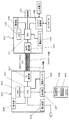
図1を参照し、連動システムは、電子機器の1つであるデジタルカメラ100と、外部装置の1つであるテレビ受像機200とで構成される。デジタルカメラ100とテレビ受像機200はHDMIケーブル300で接続可能である。HDMIケーブル300は、データ線とコントロール線を含み、デジタルカメラ100とテレビ受像機200のデータ信号とコントロール信号の通信を可能にする。
1. Configuration of Interlocking System Referring to FIG. 1, the interlocking system includes a
1−1.デジタルカメラ100の構成及び基本動作
図2に示すように、デジタルカメラ100は、カメラCPU101と、カメラメモリ102と、カメラ通信部103と、カメラ電源スイッチ104と、バッテリ装着部105と、撮像部106と、を備える。デジタルカメラ100は、撮像部106で被写体像を撮像して画像データを生成し、この生成した画像データをカメラメモリ102に記憶する。デジタルカメラ100は電源状態として「ON」と「OFF」を有する。
1-1. Configuration and Basic Operation of
デジタルカメラ100は連動モードを有し、連動モードを「ON」または「OFF」に設定が可能である。デジタルカメラ100は、連動モードが「ON」に設定されると、テレビ受像機200との間で連動動作を行なう。なお、本実施の形態において、連動モードの設定は専用釦(図示せず)等を用いて変更可能である。例えば、連動モードの設定は、デジタルカメラ100の液晶モニタ上に表示された設定画面を介してなされてもよい。または、操作部107が操作されることで連動モードの設定が変更されてもよい。
The
カメラCPU101は、マイクロコンピュータ等で構成され、デジタルカメラ100の各部を制御する。カメラメモリ102は、ROMやRAM等で構成され、各種情報や画像データ等を記憶可能である。
The
カメラ通信部103は、HDMIケーブル300を接続可能なハードウェアインターフェースである。カメラ通信部103は、テレビ受像機200に含まれるTVCPU201からのデータ信号やコントロール信号をカメラCPU101に出力できるとともに、カメラCPU101からのデータ信号やコントロール信号をTVCPU201に出力できる。
The
カメラ電源スイッチ104は、デジタルカメラ100の外装に設けられる釦等で構成される。カメラ電源スイッチ104は、使用者から指示を受け付けて、電源切換信号をカメラCPU101に送信する。カメラCPU101は、電源切換信号を受ける度に電源状態をONまたはOFFに切り換える。つまり、デジタルカメラ100の電源状態がOFFである場合、カメラCPU101は、カメラ電源スイッチ104から電源切換信号を受信すると、デジタルカメラ100の電源状態をOFFからONに切り換える。また、デジタルカメラ100の電源状態がONである場合、カメラCPU101は、カメラ電源スイッチ104から電源切換信号を受信すると、デジタルカメラ100の電源状態をONからOFFに切り換える。
The
バッテリ装着部105は、ACアダプタに接続されるDCカプラ又は二次電池を装着可能な部材である。バッテリ装着部105は、ACアダプタや二次電池等の電源が接続されると、デジタルカメラ100の各部に電力を供給可能である。バッテリ装着部105は、デジタルカメラ100の電源状態がONである場合、装着された電源からデジタルカメラ100の各部に電力を供給する。バッテリ装着部105には、装着された電源の種類(ACアダプタに接続される電源、二次電池等)を判別できる回路が設けられている。具体的には、バッテリ装着部105は、電源が装着された際に電源から供給される電力に基づいて電源の種類の判断を行なうようにしている。電源種類の判断方法は特にこれに限定されるものではない。
The
撮像部106は、CCDイメージセンサやCMOSイメージセンサ等の撮像素子で構成され、レンズ系によって形成された被写体像を撮像し、画像データを生成する。撮像部106から出力された画像データは、図示しない画像処理プロセッサ等で画像処理が施され、カメラCPU101に入力される。カメラCPU101は、画像データをカメラメモリ102に記録する。
The
1−2.テレビ受像機の構成及び基本動作
テレビ受像機200は、TVCPU201と、TVメモリ202と、TV通信部203と、TV電源スイッチ204と、電源回路205と、表示部206と、受光部207と、を備える。テレビ受像機200は、表示部206に画像を表示可能である。また、テレビ受像機200は、リモコン400から操作信号を受信して、操作信号に応じた各部を制御する。テレビ受像機200は電源状態として「ON」と「OFF」以外に「待機」を有する。「待機」の電源状態とは、外部からテレビ受像機200に対して電源が供給されているが、少なくとも、表示部206には電力供給せず映像が表示されていない状態であるつまり、電源状態が「待機」の場合、テレビ受像機200において映像表示は行われないが、リモコン400からの操作信号の受信は可能である。
1-2. Configuration and Basic Operation of Television Receiver The
テレビ受像機200は、外部機器(本例では、デジタルカメラ100)との連携動作を可能とする「連動モード」を有する。連動モードは、専用釦等を介して「ON」、「OFF」が設定可能になっている。テレビ受像機200は、連動モードが「ON」に設定されると、デジタルカメラ100との連携動作を行なう。連動モードの設定は表示部206に表示された設定画面を介して、リモコン400の操作信号に応じて設定を変更できるようにしてもかまわない。
The
テレビ受像機200は連携動作においてさらに「電源オン連動」の設定を有する。電源オン連動とは、外部機器(本例では、デジタルカメラ100)によるテレビ受像機200の電源制御が可能となる設定である。電源オン連動の設定は「ON」または「OFF」が設定可能である。テレビ受像機200は、電源オン連動が「ON」に設定されると、デジタルカメラ100から電源コントロール信号を受信して、電源状態を待機からONに変更されることが可能となる。具体的には、電源オン連動が「ON」のとき、テレビ受像機200の電源状態が待機の場合であって、かつ、デジタルカメラ100から電源コントロール信号を受信した場合、テレビ受像機200は、その電源状態を待機からONに切り換える動作を行う。なお、デジタルカメラ100とテレビ受像機200の間の連携動作の詳細は後述する。テレビ受像機200は、表示部206に表示された設定画面により、リモコン400の操作信号に応じて電源オン連動の設定が変更できるようになっている。
The
TVCPU201は、マイクロコンピュータ等で構成され、テレビ受像機200の各部を制御する。TVメモリ202は、ROMやRAM等で構成され、各種情報や画像データ等を記憶可能である。
The
TV通信部203は、HDMIケーブル300を接続可能なハードウェアインターフェースである。TV通信部203は、デジタルカメラ100に含まれるカメラCPU101からのデータ信号やコントロール信号をTVCPU201に出力できるとともに、TVCPU201からのデータ信号やコントロール信号をカメラCPU101に出力できる。
The
TV電源スイッチ204は、テレビ受像機200の外装に設けられた釦等で構成される。TV電源スイッチ204は、使用者から指示を受け付けて、電源切換信号をTVCPU201に送信する。TVCPU201は電源切換信号に応じて電源状態を切り換える。具体的には、テレビ受像機200の電源状態がOFFである場合、TVCPU201は、TV電源スイッチ204から電源切換信号を受信すると、テレビ受像機200の電源状態をOFFからONに切り換える。また、テレビ受像機200の電源状態が待機である場合、TVCPU201は、TV電源スイッチ204から電源切換信号を受信すると、テレビ受像機200の電源状態を待機からOFFに切り換える。テレビ受像機200の電源状態がONである場合、TVCPU201は、TV電源スイッチ204から電源切換信号を受信すると、テレビ受像機200の電源状態をONからOFFに切り換える。なお、TVCPU201は、現在の電源状態をTVメモリ202に記憶する。これによって、停電が発生した場合のように商用電源からの電力が途絶えた後であって、電力が再度供給された場合、異常終了と判断して、停電前の電源状態に復帰させる。つまり、電源状態がONの状態で商用電源からの電力が遮断された後、電力が復帰した場合、電源状態をOFFからONにしてテレビ受像機200を起動する。また、電源状態が待機の状態で、商用電源からの電源が遮断された後、電力が復帰した場合、電源状態をOFFから待機にしてテレビ受像機200を起動する。
The
電源回路205は、商用電源からの電力を各部に供給する回路である。電源回路205は、コードに接続され、コードの先端には差し込みプラグが設けられている。差込プラグが、コンセント等に差し込まれると、商用電源から電力が供給される。
The
表示部206は、液晶やPDP等によって構成されるモニタである。表示部206は、TVCPU201から出力された画像を表示する。
The
受光部207は、リモコン400からの操作信号を受信する光センサである。受光部207は受信した操作信号をTVCPU201に送信する。TVCPU201は、リモコン400からの操作信号に応じて各種動作を行なう。
The
リモコン400は操作部401と送信部402とで構成される。操作部401は、リモコン400の外装に設けられる複数の操作釦である。送信部402は、操作部401で受け付けた操作に応じた光学的な操作信号を出力する。操作部401は電源釦を含む。電源釦が操作されると、電源指令信号が出力される。テレビ受像機200の受光部207はリモコン400から電源指令信号を受信し、その電源指令信号をTVCPU201に送信する。TVCPU201は電源指令信号を受信すると、テレビ受像機200の電源状態を切り換える。具体的には、TVCPU201は、テレビ受像機200の電源状態がONであるときに電源指令信号を受信すると、電源状態をONから待機に切り換える。一方、テレビ受像機200の電源状態が待機である場合に電源指令信号を取得すると、TVCPU201は電源状態を待機からONに切り換える。なお、テレビ受像機200の電源状態がOFFの場合は、受光部207に電力が供給されていないため、受光部207はリモコンからの電源指令信号を受信せず、テレビ受像機200の電源状態は変化しない。
The remote control 400 includes an
2.用語の対応
デジタルカメラ100は電子機器及び第1の機器の一例である。カメラ通信部103は通信手段の一例である。カメラCPU101は、検知手段、設定手段、受信手段及び制御手段の一例である。電源コントロール信号はコントロール信号の一例である。バッテリ装着部105は装着手段及び判別手段の一例である。カメラ操作部107は操作受付手段の一例である。テレビ受像機200は外部装置及び第2の機器の一例である。TV通信部203は受信手段の一例である。TVCPU201は変更手段の一例である。待機状態は第1の電源状態の一例であり、ON状態は第2の電源状態の一例である。
2. Term Correspondence The
3.連動システムの動作
上記のように構成した連動システムの動作について図3等のフローチャートを用いて説明する。
3. Operation of Interlocking System The operation of the interlocking system configured as described above will be described with reference to the flowchart of FIG.
図3及び図5のフローチャートはデジタルカメラ100の動作例を示す。図3は、電源状態がONでかつ連携モードが「ON」に設定されたときに開始されるデジタルカメラ100の動作を示す。図5は、デジタルカメラ100の連携動作の一例を示す。また、図4、図6及び図7のフローチャートは、テレビ受像機200の動作例である。図4及び図6は、電源状態が待機又はONであり、連携モードが「ON」に設定されたテレビ受像機200の動作を示す。また、図7は、電源状態が待機又はONであり、連携モードが「ON」に設定され、かつ電源オン連動の設定が「ON」に設定されたときに開始されるテレビ受像機200の動作を示す。つまり、本実施の形態では、テレビ受像機200において電源オン連動の設定が「OFF」に設定された場合、図7に示す動作は行なわれない。
3 and 5 show an example of the operation of the
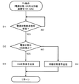
最初に、図3を用いて、電源状態がONでかつ連携モードが「ON」に設定されたデジタルカメラ100の動作を説明する。カメラCPU101は、デジタルカメラ100の電源状態がONにされ、連携モードが「ON」に設定されると図3に示す動作を開始する。
First, the operation of the
まず、カメラCPU101は、ポーリング信号をTVCPU201に送信する(A1)。カメラCPU101は、通信可能を示す信号をTVCPU201から取得したか否かを判別する(A2)。カメラCPU101は、通信可能を示す信号を受信するまで、ポーリング信号を送信し続ける(A1〜A2)。カメラCPU101は、ポーリング信号を周期的に(例えば1秒毎に)送信する。このように、カメラCPU101は、TVCPU201から通信可能を示す信号が返信されるまで、ステップA1〜A2を繰り返す。
First, the
以上のようなカメラCPU101の動作に対して、TVCPU201は、テレビ受像機200の電源状態がON又は待機であり、連携モードが「ON」に設定されている場合、図4に示すように動作する。すなわち、図4に示すように、TVCPU201は、カメラCPU101からポーリング信号を取得したか否かを判別する(C1)。TVCPU201は、カメラCPU101からポーリング信号を取得すると、通信可能を示す信号(Ack)をカメラCPU101に送信する(C2)。
In contrast to the operation of the
カメラCPU101は、TVCPU201からポーリング信号に対する返信(通信可能を示す信号)を受信しない場合、TVCPU201と通信不可能と判断できる。一方、カメラCPU101は、TVCPU201からポーリング信号に対する返信を受信した場合、TVCPU201と通信可能と判断できる。以上のようにして、カメラCPU101は、TVCPU201との通信が不可能から可能になったことを検知できる。
If the
例えば、デジタルカメラ100とテレビ受像機200が、HDMIケーブル300で接続されていない状態にあるとする。この場合でも、カメラCPU101は、ポーリング信号を送信する。しかし、デジタルカメラ100は、テレビ受像機200とHDMIケーブルで接続されていないため、TVCPU201からの返信を受信することはできない。したがって、カメラCPU101は、通信不可能と判断する。ここでデジタルカメラ100とテレビ受像機200がHDMIケーブル300で接続されたとする。この場合、カメラCPU101は、継続してポーリング信号を送信しているため、TVCPU201は、カメラCPU101からのポーリング信号に応じて、通信可能を示す信号を返信する。なお、TVCPU201は、テレビ受像機200の電源状態がOFFの場合、又は、連動モードが「OFF」に設定されている場合は、図4に示すような動作を行なわない。したがって、そのような場合、カメラCPU101は、ポーリング信号に対する返信(通信可能を示す信号)を受信できないので、通信不可能と判断する。同様の考え方で、デジタルカメラ100とテレビ受像機200がHDMIケーブルで接続されていない場合、カメラCPU101は、ポーリング信号をテレビ受像機200に送信することができない。したがって、デジタルカメラ100にHDMIケーブルが接続されていない場合、カメラCPU101は、テレビ受像機200と通信不可能と判断する。
For example, assume that the
図3に戻って、カメラCPU101は、TVCPU201から通信可能を示す信号を受信した場合(ステップA2でYES)、連携動作を開始する(A3)。連携動作の詳細は図5を参照して後述する。すなわち、図3に示す制御と図5に示す制御とは並列して動作する。
Returning to FIG. 3, when the
連携動作の開始後、カメラCPU101はポーリング信号を送信する(A4)。その後、カメラCPU101は、通信可能を示す信号を受信したか否かを判断する(A5)。カメラCPU101は、通信可能を示す信号を受信している間、ステップA4及びA5の処理を繰り返す。これによって、カメラCPU101は、TVCPU201に対する通信が可能から不可能になったことを検知できる。
After the start of the cooperative operation, the
例えば、デジタルカメラ100とテレビ受像機200がHDMIケーブル300で接続されているとする。さらに、テレビ受像機200の電源状態が待機であり、電源オン連動が「ON」に設定されているとする。この場合、カメラCPU101は、ポーリング信号をTVCPU201に送信すると、TVCPU201から通信可能を示す信号を取得することができる。このような場合に、停電等によって、テレビ受像機200の電源状態が待機からOFFに変更されたとする。テレビ受像機200の電源状態がOFFに変更されると、TVCPU201は図4に示す動作を実行しなくなり、カメラCPU101は、ポーリング信号に対する返信を受信できなくなる。したがって、カメラCPU101は、通信が可能から不可能になったことを検知できる。
For example, it is assumed that the
このようにカメラCPU101は、ステップA5で、通信可能を示す信号を受信できなくなると、連携動作(図5に示す動作)を終了させる(A6)。これは、デジタルカメラ100がテレビ受像機200と通信不可能であるためである。このステップA6の動作によって、図3と図5の並列動作が終了する。ステップA6の後、ステップA1に戻って上記の動作を行う。
As described above, when the
3.1 連携動作
次に、図5を用いてデジタルカメラ100における連携動作の詳細を説明する。
まず、カメラCPU101は、電源状態を要求する信号をテレビ受像機200(TVCPU201)に送信する(F1)。
3.1 Cooperation Operation Next, details of the cooperation operation in the
First, the
ここでテレビ受像機200は電源状態を要求する信号を受信すると、図6に示す動作を行なう。すなわち、図6に示すように、TVCPU201は、電源状態を要求する信号を受信すると(D1)、テレビ受像機200の電源状態がONであるか否かを判別する(D2)。TVCPU201は、電源状態がONである場合、ON状態を示す信号をカメラCPU101に送信する(D3)。一方TVCPU201は、電源状態がONでない場合、すなわち電源状態が待機である場合、待機状態を示す信号をカメラCPU101に送信する(D4)。
Here, when the
カメラCPU101は、TVCPU201から電源状態を示す情報を受信するまで待機する(F2)。これによってカメラCPU101は、テレビ受像機200の電源状態を取得することができる。
The
カメラCPU101は、TVCPU201から電源状態を示す情報を受信すると、受信した電源状態を示す情報がONを示すか否かを判別する(F3)。カメラCPU101は、受信した電源状態がONを示す場合、連携情報をカメラメモリ102に設定する(F4)。
Upon receiving the information indicating the power state from the
ここで、連携情報について説明する。連携情報とは、デジタルカメラ100が、現在の連携が可能になる前にテレビ受像機200との間で連携動作を行っていたか否か、すなわち、デジタルカメラ100とテレビ受像機200間の連携動作を開始したか否かを示す情報である。カメラメモリ102に連携情報を格納可能な領域が設けられている。その連携領域に、連携情報として「0」又は「1」のいずれかが設定される。「0」は、現在の連携が可能になる前にテレビ受像機200との間で連携動作を行っていないこと、すなわち、デジタルカメラ100とテレビ受像機200間の連携動作が開始されていないことを示す。「1」は、現在の連携が可能になる前にテレビ受像機200との間で連携動作を行っていたこと、すなわち、デジタルカメラ100とテレビ受像機200間の連携動作を開始したことを示す。連携情報は、デジタルカメラ100の電源がOFFからONにされたときに「0」に初期化(リセット)される。その後、デジタルカメラ100とテレビ受像機200の連携が最初に可能になった時点で、連係情報は「1」に設定される。この連携情報を参照することによって、デジタルカメラ100が電源ONになった後にデジタルカメラ100とテレビ受像機200とが連携していたことを判断できる。ステップF4においては、連携情報として「1」が設定される。
Here, the cooperation information will be described. The cooperation information refers to whether or not the
図5に戻って、ステップF4の動作が完了すると、連携を行なうための各種動作に移行する(F5)。連携を行なうための各種動作は、特に限定されない。例えば、デジタルカメラ100が、リモコン400の操作信号(テンキー情報)をテレビ受像機200から取得して、この操作信号に応じた動作を行なう場合などが考えられる。
Returning to FIG. 5, when the operation of step F4 is completed, the operation proceeds to various operations for cooperation (F5). Various operations for performing cooperation are not particularly limited. For example, the
一方、ステップF3において、カメラCPU101は、受信した電源状態を示す情報がONを示していない場合、すなわち、電源状態が待機の場合、今回の通信が不可能から可能になる前にテレビ受像機200と連携していたか否かを判断する(F6)。具体的には、連携情報が「1」に設定されているか否かを判別する(F6)。
On the other hand, in step F3, when the received information indicating the power state does not indicate ON, that is, when the power state is standby, the
カメラCPU101は、連携情報が「1」に設定されている場合、連携動作を終了する。この場合、テレビ受像機200の電源をONにする電源コントロール信号はTVCPU201に送信されない。すなわち、電源コントロール信号のテレビ受像機200への送信が禁止される。一方、カメラCPU101は、連携領域の情報が「1」でない場合、電源コントロール信号をTVCPU201に送信する(F7)。
When the cooperation information is set to “1”, the
TVCPU201は電源コントロール信号を受信すると、図7に示す動作を行なう。すなわち、図7に示すように、TVCPU201は、電源コントロール信号を受信すると(E1)、テレビ受像機200の電源状態を待機からONに変更する(E2)。
When the
図5に戻って、カメラCPU101は、電源コントロール信号を送信後、連携情報に「1」を設定し(F8)、ステップF1に戻る。つまり、カメラCPU101は、電源状態を要求する信号を、TVCPU201に送信する。そして、カメラCPU101は、電源状態を取得し、電源状態がONになったことを検知すると、連携情報「1」をカメラメモリ102に記憶する(F4)。そして、カメラCPU101は、各種動作に移行する。
Returning to FIG. 5, after transmitting the power control signal, the
なお、カメラCPU101は、カメラ操作部107が使用者により操作された場合、カメラメモリ102に記憶された連携情報をリセットする。つまり、カメラ操作部107が操作された場合、カメラメモリ102に記憶された連携情報を「1」から「0」に設定する。このようにすれば、使用者がカメラ操作部107を操作することで、デジタルカメラ100からテレビ受像機200にコントロール信号を送信できるようにできる。つまり、カメラ操作部107が操作されることで、連携情報が「0」にリセットされるため、カメラCPU101は、通信が不可能から可能になったことを検知し、かつ、テレビ受像機200の電源状態が待機である場合に、電源コントロール信号をテレビCPU201に送信できるようになる。
The
以下、具体例を挙げて従来の連動システムの動作と本実施形態の連動システムの動作の差異を説明する。 Hereinafter, the difference between the operation of the conventional interlocking system and the operation of the interlocking system of the present embodiment will be described with specific examples.
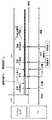
図8は、従来の連動システムの動作の具体例を説明するための図である。図9は、本実施の形態の連動システムの動作の具体例を説明するための図である。 FIG. 8 is a diagram for explaining a specific example of the operation of the conventional interlocking system. FIG. 9 is a diagram for explaining a specific example of the operation of the interlocking system of the present embodiment.
最初に、図8を用いて従来の連動システムの動作を説明する。最初、デジタルカメラの電源がOFFであり、テレビ受像機の電源が待機であり、デジタルカメラとテレビ受像機はHDMIケーブルで接続されているとする。まず、デジタルカメラの電源がONにされると、デジタルカメラは前述の手順にしたがい通信不可能から可能になったことを検知する。デジタルカメラは、TVの電源状態が待機であるため、電源コントロール信号をテレビ受像機に送信する。テレビ受像機は電源コントロール信号にしたがい電源をONにする。その後、テレビ受像機は、使用者により電源をONから待機に変更され、その後停電が発生すると、テレビ受像機の電源はOFFになる。すると、デジタルカメラは、通信が可能から不可能になったことを検知する。その後、停電が終了し、電力が復帰すると、テレビ受像機の電源が待機状態に戻る。このため、デジタルカメラは通信不可能から可能になったことを検知する。テレビ受像機の電源状態が待機であるため、デジタルカメラは電源コントロール信号をテレビ受像機に送信する。よって、テレビ受像機は、電源コントロール信号にしたがい電源をONにする。以後、テレビ受像機の電源はONのまま放置されるという問題がある。 First, the operation of the conventional interlocking system will be described with reference to FIG. First, it is assumed that the power of the digital camera is OFF, the power of the TV receiver is standby, and the digital camera and the TV receiver are connected by an HDMI cable. First, when the power of the digital camera is turned on, the digital camera detects that the communication is possible because the communication is impossible according to the above-described procedure. Since the power state of the TV is standby, the digital camera transmits a power control signal to the television receiver. The television receiver is turned on according to the power control signal. Thereafter, the television receiver is switched from ON to standby by the user, and when a power failure occurs thereafter, the television receiver is turned OFF. Then, the digital camera detects that communication is no longer possible. Thereafter, when the power failure ends and the power returns, the power of the television receiver returns to the standby state. For this reason, the digital camera detects that it has become possible because communication is impossible. Since the power state of the television receiver is standby, the digital camera transmits a power control signal to the television receiver. Therefore, the television receiver turns on the power according to the power control signal. Thereafter, there is a problem that the power of the television receiver is left on.
次に、図9を用いて本実施形態の連動システムの動作を具体例を挙げて説明する。最初、デジタルカメラ100の電源がOFFであり、テレビ受像機200の電源が待機であり、デジタルカメラ100とテレビ受像機200がHDMIケーブル300で接続されているとする。この状態で、デジタルカメラ100の電源がONにされると、デジタルカメラ100は、通信不可能から可能になったことを検知する。この場合、テレビ受像機200の電源状態が待機であり(図5のステップF3でNO)、連携情報は初期値である「0」であるため、デジタルカメラ100は電源コントロール信号をテレビ受像機200に送信する(図5のステップF7)。そして、デジタルカメラ100は連携情報を「1」に設定し(図5のステップF8)、カメラメモリ102に記憶する。テレビ受像機200は電源コントロール信号にしたがい電源をONにする。
Next, the operation of the interlocking system of this embodiment will be described with a specific example with reference to FIG. First, it is assumed that the
この後、テレビ受像機200の電源がONから待機に変更され、その後、停電が発生すると、停電によりテレビ受像機200の電源がOFFになる。そのとき、デジタルカメラ100は、通信が可能から不可能になったことを検知する。その後、停電が終了すると、テレビ受像機200の電源状態が待機に戻る。そのとき、デジタルカメラ100は、通信不可能から可能になったことを検知する。この際、テレビ受像機200の電源状態が待機ではあるが、連携情報が「1」に設定されているため(図5のステップF6でYES)、デジタルカメラ100は、電源コントロール信号をテレビ受像機200に送信しない。よって、デジタルカメラ100は、停電によってテレビ受像機200の電源状態がOFFにされ、その後停電が終了し、テレビ受像機200の電源状態がOFFから待機状態に戻った場合であっても、テレビ受像機200の電源を待機状態からONに制御することを防止できる。
Thereafter, when the power of the
以上のように、本実施形態のデジタルカメラ100は、連携情報を参照して、以前にデジタルカメラ100とテレビ受像機200間で連携動作が行われていたか否かを判断し、連携動作が行われていた場合は、電源コントロール信号のテレビ受像機200への送信を行わない(禁止する)。これにより、停電が発生したときに勝手にテレビ受像機200の電源が待機状態からONに変更されるという不具合を防止できる。
As described above, the
3.2 他の連携動作例
図10を用いてデジタルカメラ100における連携動作の別の例を説明する。まず、カメラCPU101は、以前の連携動作の有無を考慮して連携情報を設定する(B1)。設定した連携情報はカメラメモリ102に記憶される。本例では、連携情報として「0」、「1」、「2」の何れかの値が設定され得る。「0」は初期値であり、以前に連携がされていなかったこと(連携が未だ開始されていないこと)を示す。連携情報は、デジタルカメラ100の電源がOFFからONにされたときに「0」に初期化される。「1」は以前に連携がされていなかったこと(連携が未だ開始されていないこと)を、「2」は以前に連携がされていたこと(連携が開始されていたこと)をそれぞれ示す。
3.2 Other Example of Cooperation Operation Another example of the cooperation operation in the
カメラCPU101はステップB1において連携情報を設定する際、現在の連携が可能になる前(つまり、現在の通信が可能になる前)に連携したことがない場合、すなわち連携情報が「0」の場合、連携情報に「1」を設定してカメラメモリ102に記憶する。一方、現在の連携が可能になる前に、連携したことがある場合、すなわち連携情報が「1」の場合、カメラCPU101は連携情報に「2」を設定し、カメラメモリ102に記憶する。すなわち、カメラCPU101は、カメラメモリ102に格納された連携情報が「0」である場合、新たに連携情報に「1」を設定し、連携情報が「1」である場合、新たに連携情報に「2」を設定する。
When the
カメラCPU101は、連携情報を設定した後、電源状態を要求する信号をTVCPU201に送信する(B2)。テレビ受像機200は電源状態を要求する信号を受信すると、前述のように図6に示す動作を行なう。
After setting the cooperation information, the
その後、カメラCPU101は、TVCPU201から電源状態を示す信号を取得するまで待機する(B3)。これによってカメラCPU101は、テレビ受像機200の電源状態を取得することができる。
Thereafter, the
カメラCPU101は、TVCPU201からテレビ受像機200の電源状態を取得すると、電源状態がONを示すか否かを判別する(B4)。カメラCPU101は、電源状態がONを示す場合、連携を行なうための各種動作に移行する(B5)。各種動作は特に限定されず、例えば、デジタルカメラ100が、リモコン400の操作信号(テンキー情報)をテレビ受像機200から取得して、その操作信号に応じた行う動作が考えられる。
When the power state of the
カメラCPU101は、電源状態がONを示さない場合すなわち電源状態が待機の場合、連携情報を参照して、今回の通信が不可能から可能になる前にテレビ受像機200と連携したことがあるか否かを判別する(B6)。具体的には、カメラCPU101は、電源状態がONでない場合(すなわち、電源状態が待機である場合)、連携情報が「2」であるか否かを判別する。
If the
連携領域の情報が「2」でない場合、カメラCPU101はステップB8に移行する。一方、連携領域の情報が「2」である場合、カメラCPU101は、デジタルカメラ100に設けられた十字キー等のカメラ操作部107が、所定時間(例えば、10分)以内に操作されたか否かを判別する(B7)。所定時間は例えば電源状態を受信した時点またはステップB7の処理に移行した時点から計測すればよい。カメラ操作部107が、所定時間以内に操作された場合、カメラCPU101はステップB8に移行する。一方、カメラ操作部107が所定時間以内に操作されなかった場合、カメラCPU101は連携動作を終了する。なお、カメラCPU101は所定時間以内に操作を受け付けることで、使用者の存在を確認できるようにしている。
If the information of the cooperation area is not “2”, the
つまり、前述のように、停電等によってテレビ受像機の電源がONまたは待機からOFFになり、停電終了後に待機状態になった場合、デジタルカメラからの制御に応じて、自動的にテレビ受像機の電源がONにされ、その後ONのまま放置されてしまうという問題があった。使用者がデジタルカメラの近くに存在していれば、テレビ受像機の電源が自動的にONになったとしても直ぐにOFFにすることが可能である。したがって、現在の通信可能を検知する以前に連携していた場合であっても、カメラ操作部107で使用者からの指示を受け付けた場合は、デジタルカメラ100は、電源コントロール信号をTVCPU201に送信するようにする。なお、ステップB7においてカメラ操作部107が所定時間以内に操作された場合に、連携情報を「0」にリセットしてもよい。
In other words, as described above, when the power of the television receiver is turned on or off from standby due to a power failure or the like, and enters the standby state after the power failure ends, the television receiver is automatically turned on according to the control from the digital camera. There was a problem that the power was turned on and then left on. If the user is in the vicinity of the digital camera, even if the power of the television receiver is automatically turned on, it can be turned off immediately. Accordingly, even when the current cooperation is detected before being detected, when the
ステップB8において、カメラCPU101は、電源コントロール信号をTVCPU201に送信する。TVCPU201は電源コントロール信号を受信すると、前述のように図7に示す動作を行ない、テレビ受像機200の電源状態を待機からONに変更する。
In step B <b> 8, the
なお、カメラCPU101は、ステップB8の後、ステップB2に戻って、電源状態の要求動作を行なう。その後、カメラCPU101は、ステップB3で電源状態を取得し、電源状態がONになったことを検知すると、ステップB5に移行し、各種動作を実行する。
The
図11を用いて図10に示す連携動作を具体例を挙げて説明する。図11は、具体例を用いて図10に示す連携動作を説明するための図である。最初、デジタルカメラ100の電源がOFFであり、テレビ受像機200の電源が待機であり、デジタルカメラ100とテレビ受像機200はHDMIケーブル300で接続されているとする。この状態で、デジタルカメラ100の電源がONにされる。これにより、デジタルカメラ100は通信不可能から可能になったことを検知する。この際、連携情報はデジタルカメラ100の電源ONにより「0」に初期化されているため、デジタルカメラ100は連携情報に「1」を設定する(図10のステップB1)。デジタルカメラ100は、テレビ受像機200の電源状態が待機であり(図10のステップB4でNO)、通信可能を検知する前に連携がなされていない(連係情報=1)ため(図10のステップB6でYES)、電源コントロール信号をテレビ受像機200に送信する(図10のステップB8)。テレビ受像機200は電源コントロール信号にしたがい電源をONにする。その後、使用者によりテレビ受像機200の電源がONから待機に変更される。その後、停電が発生すると、テレビ受像機200の電源がOFFになり、デジタルカメラ100は通信が可能から不可能になったことを検知する。停電が終了すると、テレビ受像機200の電源が待機状態に戻る。このため、デジタルカメラ100は、通信不可能から可能になったことを検知する。その際、デジタルカメラ100は、記憶した連携情報が「1」であるので、連携情報を「2」に更新する(図10のステップB1)。デジタルカメラ100は、TVの電源状態が待機であるが、連携情報が「2」であるため(図10のステップB6でYES)、電源コントロール信号を送信しない。このように、図10に示す動作によっても、デジタルカメラ100は、停電が発生したときにテレビ受像機200の電源が待機状態からONに制御することを防止できる。
The cooperative operation shown in FIG. 10 will be described using a specific example with reference to FIG. FIG. 11 is a diagram for explaining the cooperative operation shown in FIG. 10 using a specific example. Initially, it is assumed that the power of the
4.まとめ
本実施の形態は、電源コントロール信号を受信するTV通信部203と、TV通信部203で受信した電源コントロール信号に応じて、電源状態を待機からONに変更するTVCPU201と、を有するテレビ受像機200と通信可能なデジタルカメラ100である。
4). Summary This embodiment is a television receiver having a
デジタルカメラ100は、テレビ受像機200と通信するカメラ通信部103と、カメラ通信部103を介したテレビ受像機200との通信が不可能から可能になったことを検知するカメラCPU101と、カメラCPU101によってテレビ受像機200との通信が可能になったことを検知した場合、テレビ受像機200との連携を示す信号をカメラメモリ102に記憶するカメラCPU101と、カメラCPU101によってテレビ受像機200との通信が可能になったことを検知した場合、カメラ通信部103を介してテレビ受像機200の電源状態を示す信号を取得するカメラCPU101と、カメラCPU101によって取得した電源状態を示す信号が待機状態を示す場合であって、カメラCPU101によって通信が可能になったことを検知する以前において連携を示す情報がカメラメモリ102に記憶されていない場合、カメラ通信部103を介して電源コントロール信号をテレビ受像機200に送信するカメラCPU101と、を備える。
The
このようにすれば、テレビ受像機200から取得した電源状態を示す信号が、待機状態を示す場合であって、今回の通信が可能になった以前に連携を示す信号がカメラメモリ102に記憶されていない場合、テレビ受像機200に電源コントロール信号を送信できるようになる。したがって、デジタルカメラ100は、より適切なタイミングで電源コントロール信号を送信できるようになる。
In this way, the signal indicating the power state acquired from the
(他の実施の形態)
本発明の実施の形態として、実施の形態1を例示した。しかし、本発明は、実施の形態1に限定されず、他の実施の形態においても実現可能である。そこで、本発明の他の実施の形態を以下にまとめて説明する。
(Other embodiments)
Embodiment 1 was illustrated as embodiment of this invention. However, the present invention is not limited to the first embodiment, and can be implemented in other embodiments. Therefore, other embodiments of the present invention will be described collectively below.
実施の形態では、電子機器の一例として、デジタルカメラ100を用いた例を説明した。しかし、これに限られず、電子機器には、携帯電話、ムービー、携帯TV、ポータブルBDプレーヤー、ポータブルDVDプレーヤー等を用いることができる。また、外部装置の一例として、テレビ受像機200を用いた例を説明した。しかし、これに限られず、外部装置には、BDレコーダー、DVDレコーダー、プリンター、プロジェクター等を用いることができる。
In the embodiment, the example in which the
また、デジタルカメラ100への電源が商用交流電源でない場合、例えば、デジタルカメラ100に二次電池が装着された場合にのみ、図3及び図5または図10の動作をさせるようにしてもかまわない。本実施の形態では、デジタルカメラ100の電源状態がONであり、連動モードが「する」に設定された場合、図3及び図5または図10の動作をするようにしたが、この動作に限定されない。すなわち、バッテリ装着部105に装着された電源が電池電源であると判断した場合にのみ、カメラCPU101が図3及び図5または図10の動作を実行するようにしてもよい。デジタルカメラ100が商用交流電源に接続された場合、停電の発生及び停電の終了により連携情報がリセットされてしまい、図5または図10の動作を本来の目的が得られるように正しく実行できないからである。このため、デジタルカメラ100が停電の影響を受けない状態になる、デジタルカメラ100に二次電池が装着された場合にのみ、図3及び図5または図10の動作をさせるようにしてもよい。
Further, when the power source for the
また、本実施の形態では、デジタルカメラ100は、ポーリング信号をテレビ受像機200に繰り返し送信して、返信を受信することで、テレビ受像機200との通信が不可能から可能になったことを検知するようにした。しかし、これに限られない。
Further, in the present embodiment, the
また、本実施の形態では、デジタルカメラ100と、テレビ受像機200とを、HDMIケーブル300で接続できるようにした。しかし、これに限られず、コントロール信号を送信可能な他のケーブルで接続してもよい。また、本実施の形態は、有線によってデジタルカメラとテレビ受像機を接続するようにした。これに限られず、無線によって接続するようにしてもかまわない。なお、上記のように構成を変えた場合、テレビ通信部やカメラ通信部のハードウェアインターフェースを交換して、対応する必要がある。
In the present embodiment, the
また、本実施の形態では、デジタルカメラ100とテレビ受像機200を、HDMIケーブル300を用いて直接接続するようにした。しかし、これに限られず、デジタルカメラとテレビ受像機を、間接的に接続してもかまわない。例えば、デジタルカメラとアンプを、HDMIケーブルで接続する。また、アンプとテレビ受像機を、HDMIケーブルで接続する。このように接続する。これによって、デジタルカメラとアンプを、間接的に接続することが可能になる。
In the present embodiment, the
また、上記実施形態では、外部装置の一例としてテレビ受像機を用いたが、これに限定されない。通信回線を介して他の機器から電源コントロール信号を受信できるインタフェース(例えばHDMI)を備えたものであれば、パーソナルコンピュータや携帯型の光ディスクプレーヤ、携帯型テレビ等、種々の電子機器に上記実施の形態の思想を適用することができる。また、電子機器の一例としてデジタルカメラを用いて説明したが、これに限定されない。電池駆動が可能でかつ通信回線を介して他の機器へ電源コントロール信号を送信できるインタフェース(例えばHDMI)を備えたものであれば、ムービーカメラ、携帯電話、携帯情報端末、ポータブルBDプレーヤー、ポータブルDVDプレーヤー等、種々の電子機器に上記実施の形態の思想を適用することができる。 Moreover, in the said embodiment, although the television receiver was used as an example of an external device, it is not limited to this. As long as an interface (for example, HDMI) capable of receiving a power control signal from another device via a communication line is provided, the above-described embodiment is applied to various electronic devices such as a personal computer, a portable optical disc player, and a portable television. The idea of form can be applied. In addition, although a digital camera has been described as an example of the electronic apparatus, the present invention is not limited to this. Movie cameras, mobile phones, personal digital assistants, portable BD players, portable DVDs, as long as they have an interface (for example, HDMI) that can be driven by a battery and can send power control signals to other devices via a communication line The idea of the above embodiment can be applied to various electronic devices such as players.
上記の思想は、上記の実施の形態に限られず、種々の実施の形態において実施可能である。 The above idea is not limited to the above embodiment, and can be implemented in various embodiments.
本発明の電子機器は、デジタルカメラ、ムービーカメラ、携帯型テレビ、携帯電話、ポータブルBDプレーヤー、ポータブルDVDプレーヤー等に用いることが可能である。 The electronic device of the present invention can be used for a digital camera, a movie camera, a portable television, a mobile phone, a portable BD player, a portable DVD player, and the like.
100 デジタルカメラ
101 カメラCPU
102 カメラメモリ
103 カメラ通信部
104 カメラ電源スイッチ
105 バッテリ装着部
106 撮像部
107 カメラ操作部
200 テレビ受像機
201 TVCPU
202 TVメモリ
203 TV通信部
204 TV電源スイッチ
205 電源回路
206 表示部
207 受光部
300 HDMIケーブル
400 リモコン
401 操作部
402 送信部
100
DESCRIPTION OF
202
Claims (13)
前記外部装置と通信する通信手段と、
前記電子機器と前記外部装置との間の連携を示す情報を記憶可能な記憶手段と、
前記通信手段を介して前記外部装置との通信が可能になったことを検知する検知手段と、
前記検知手段によって前記外部装置との通信が可能になったことを検知した場合、前記記憶手段に連携を示す情報が記憶されているか否かを判別する判別手段と、
前記判別手段によって前記記憶手段に連携を示す情報が記憶されていないと判別された場合、前記記憶手段に前記連携を示す情報を記憶させるとともに、前記外部装置の電源状態を前記第2の電源状態に制御するためのコントロール信号を前記外部装置に送信する一方、前記判別手段によって前記記憶手段に連携を示す情報が記憶されていると判別された場合、前記コントロール信号を前記外部装置に送信しない送信手段と、
を備える電子機器。 An electronic device capable of communicating with an external device and changing a power state of the external device from a first power state to a second power state,
Communication means for communicating with the external device;
Storage means capable of storing information indicating cooperation between the electronic device and the external device ;
Detection means for detecting that communication with the external device is enabled via the communication means;
A determination unit that determines whether or not information indicating cooperation is stored in the storage unit when the detection unit detects that communication with the external device is enabled;
When it is determined by the determination means that information indicating cooperation is not stored in the storage means, the storage means stores information indicating the cooperation, and the power state of the external device is set to the second power state. A control signal for controlling the transmission is transmitted to the external device. On the other hand, if the determination unit determines that information indicating cooperation is stored in the storage unit, the control signal is not transmitted to the external device. Means,
Electronic equipment comprising.
前記送信手段は、前記受信手段によって受信した信号が第1の電源状態を示した場合にのみ、前記判別手段によって前記記憶手段に連携を示す情報が記憶されていないと判別された場合に、前記記憶手段に前記連携を示す情報を記憶させるとともに、前記外部装置の電源状態を前記第2の電源状態に制御するためのコントロール信号を前記外部装置に送信する動作を行う、
請求項1に記載の電子機器。 When it is detected by the detecting means that communication with the external device is possible, the receiving means further includes a receiving means for receiving a signal indicating a power state of the external device via the communication means,
The transmitting means is only when the signal received by the receiving means indicates a first power state, and when the determining means determines that information indicating cooperation is not stored in the storage means, The storage unit stores information indicating the cooperation, and performs an operation of transmitting a control signal for controlling the power state of the external device to the second power state to the external device.
The electronic device according to claim 1.
請求項1に記載の電子機器。 The first power state is a standby state, and the second power state is an ON state.
The electronic device according to claim 1.
前記装着手段に電池電源が接続されているか否かを判断する判断手段とをさらに備え、
前記送信手段は、前記判断手段により、前記装着手段に電池電源が装着されていると判断された場合にのみ、前記判別手段によって前記記憶手段に連携を示す情報が記憶されていないと判別された場合に、前記記憶手段に前記連携を示す情報を記憶するとともに、前記外部装置の電源状態を前記第2の電源状態に制御するためのコントロール信号を前記外部装置に送信する動作を行う、
請求項1に記載の電子機器。 Mounting means to which a battery power source can be connected;
Determining means for determining whether or not a battery power source is connected to the mounting means;
The transmission means is determined by the determination means that information indicating cooperation is not stored in the storage means only when the determination means determines that a battery power source is attached to the attachment means. In this case, information indicating the cooperation is stored in the storage unit, and an operation of transmitting a control signal for controlling the power state of the external device to the second power state is performed to the external device.
The electronic device according to claim 1.
前記操作受付手段により使用者の操作が受け付けられたときは、前記受信手段によって受信した信号が第1の電源状態を示す場合、前記判別手段によって前記記憶手段に連携を示す情報が記憶されていると判別された場合でも、前記コントロール信号を前記外部装置に送信する、
請求項2に記載の電子機器。 It further comprises operation accepting means for accepting an operation on the user's electronic device,
When a user's operation is accepted by the operation accepting means, if the signal received by the receiving means indicates a first power supply state, information indicating cooperation is stored in the storage means by the determining means. Even if it is determined that, the control signal is transmitted to the external device,
The electronic device according to claim 2.
前記操作受付手段が使用者の操作を受け付けた場合、前記連携を示す情報をリセットするリセット手段と、
をさらに備える、請求項1に記載の電子機器。 Operation accepting means for accepting an operation on the electronic device of the user;
A reset means for resetting information indicating the cooperation when the operation accepting means accepts a user operation;
The electronic device according to claim 1, further comprising:
前記第1の機器と前記第2の機器間の通信が可能であるか否かを検知し、
前記第1の機器と前記第2の機器間の通信が可能になったことを検知した場合に、前記第1の機器と前記第2の機器との間の連携を示す情報が記憶されているか否かを判別し、
前記連携を示す情報が記憶されていないことを判別した場合、前記連携を示す情報を記憶するとともに、前記第2の機器の電源状態を前記第2の電源状態に制御するためのコントロール信号を前記第2の機器に送信する一方、前記連携を示す情報が記憶されていることを判別した場合、前記コントロール信号を前記第2の機器に送信しない、
電源制御方法。 A power control method for controlling a power state of a second device from a first power state to a second power state from a first device,
Detecting whether communication between the first device and the second device is possible;
Whether information indicating cooperation between the first device and the second device is stored when it is detected that communication between the first device and the second device is possible Determine whether or not
When it is determined that the information indicating the cooperation is not stored, the information indicating the cooperation is stored, and a control signal for controlling the power state of the second device to the second power state is If it is determined that information indicating the cooperation is stored while transmitting to the second device, the control signal is not transmitted to the second device.
Power control method.
前記取得した第2の機器の電源状態が第1の電源状態を示した場合にのみ、前記連携を示す情報が記憶されていないことを判別した場合に、前記連携を示す情報を記憶するとともに、前記第2の機器の電源状態を前記第2の電源状態に制御するためのコントロール信号を前記第2の機器に送信する、
請求項11に記載の電源制御方法。 If it is detected that communication between the first device and the second device is possible, further acquiring the power state of the second device,
When it is determined that the information indicating the cooperation is not stored only when the acquired power state of the second device indicates the first power state, the information indicating the cooperation is stored. Transmitting a control signal for controlling the power supply state of the second device to the second power supply state to the second device;
The power supply control method according to claim 11.
Priority Applications (1)
| Application Number | Priority Date | Filing Date | Title |
|---|---|---|---|
| JP2009208380A JP5409220B2 (en) | 2008-09-11 | 2009-09-09 | Electronic device and power supply control method |
Applications Claiming Priority (3)
| Application Number | Priority Date | Filing Date | Title |
|---|---|---|---|
| JP2008233224 | 2008-09-11 | ||
| JP2008233224 | 2008-09-11 | ||
| JP2009208380A JP5409220B2 (en) | 2008-09-11 | 2009-09-09 | Electronic device and power supply control method |
Publications (3)
| Publication Number | Publication Date |
|---|---|
| JP2010093794A JP2010093794A (en) | 2010-04-22 |
| JP2010093794A5 JP2010093794A5 (en) | 2012-09-20 |
| JP5409220B2 true JP5409220B2 (en) | 2014-02-05 |
Family
ID=42008291
Family Applications (1)
| Application Number | Title | Priority Date | Filing Date |
|---|---|---|---|
| JP2009208380A Active JP5409220B2 (en) | 2008-09-11 | 2009-09-09 | Electronic device and power supply control method |
Country Status (2)
| Country | Link |
|---|---|
| US (1) | US8185756B2 (en) |
| JP (1) | JP5409220B2 (en) |
Families Citing this family (16)
| Publication number | Priority date | Publication date | Assignee | Title |
|---|---|---|---|---|
| JP4735709B2 (en) * | 2008-11-25 | 2011-07-27 | ソニー株式会社 | Information processing apparatus and method, and program |
| CN102792707B (en) * | 2010-03-09 | 2015-08-26 | 佳能株式会社 | Video display apparatus and control method, picture output device and control method thereof |
| EP2395741A1 (en) * | 2010-06-11 | 2011-12-14 | Nagravision S.A. | Method to manage the power setting of a receiver/decoder for pay-TV |
| US9123237B2 (en) | 2010-08-04 | 2015-09-01 | Qualcomm Incorporated | Controlling a remote electronic device in a control state |
| KR20120028548A (en) * | 2010-09-15 | 2012-03-23 | 삼성전자주식회사 | Apparatus and method for information transmission between tv and mobile communication system |
| EP2626448B1 (en) * | 2010-10-04 | 2016-06-29 | Kunio Mori | Process for forming metal film, and product equipped with metal film |
| JP5085720B2 (en) * | 2010-11-30 | 2012-11-28 | 株式会社東芝 | Video display system |
| EP2663020B1 (en) * | 2011-01-06 | 2019-07-24 | LG Electronics Inc. | Network system |
| CN103092318A (en) * | 2011-11-04 | 2013-05-08 | 联想(北京)有限公司 | Power supply management method and terminal device |
| GB201314636D0 (en) * | 2013-08-15 | 2013-10-02 | Realeyes Data Services Ltd | Method of collecting computer user data |
| US20150293573A1 (en) * | 2014-04-15 | 2015-10-15 | Angelita Howard | Power Outage Entertainment System |
| JP6438245B2 (en) * | 2014-09-05 | 2018-12-12 | キヤノン株式会社 | COMMUNICATION DEVICE, ITS CONTROL METHOD, PROGRAM |
| KR102349363B1 (en) * | 2015-08-24 | 2022-01-11 | 삼성전자주식회사 | Image Processing System, Image Display Apparatus, Interface Device for Saving Power, Electronic Device and Driving Method of Image Display Apparatus |
| JP6656070B2 (en) * | 2016-04-25 | 2020-03-04 | キヤノン株式会社 | Imaging device, control method therefor, program and system |
| WO2017188019A1 (en) * | 2016-04-28 | 2017-11-02 | ソニー株式会社 | Information processing device and information processing method |
| US10964203B1 (en) * | 2018-02-20 | 2021-03-30 | Wirepath Home Systems, Llc | Method and device for HDMI CEC control |
Family Cites Families (15)
| Publication number | Priority date | Publication date | Assignee | Title |
|---|---|---|---|---|
| JPH0951584A (en) | 1995-08-07 | 1997-02-18 | Sony Corp | Remote controller |
| US5784628A (en) * | 1996-03-12 | 1998-07-21 | Microsoft Corporation | Method and system for controlling power consumption in a computer system |
| JPH10210653A (en) * | 1997-01-24 | 1998-08-07 | Nippon Columbia Co Ltd | Audio device |
| JPH11164474A (en) * | 1997-11-27 | 1999-06-18 | Nippon Columbia Co Ltd | Audio system |
| JP2000139039A (en) * | 1998-10-30 | 2000-05-16 | Toshiba Corp | Protective device for power circuit |
| JP2003017196A (en) * | 2001-07-02 | 2003-01-17 | Daiwa Dengyo Kk | Power re-supply preventing plug outlet |
| JP4239653B2 (en) * | 2003-04-01 | 2009-03-18 | 株式会社ニコン | Camera system |
| JP2004317052A (en) * | 2003-04-17 | 2004-11-11 | Fujitsu General Ltd | Control method of remote control device |
| US7251738B2 (en) * | 2003-11-21 | 2007-07-31 | Dell Products L.P. | Method of remotely controlling power to an information handling system via a peripheral bus after a loss of power |
| US7363521B1 (en) * | 2005-05-31 | 2008-04-22 | Garmin Ltd. | Method and apparatus for remote device control using control signals superimposed over Ethernet |
| JP4827643B2 (en) | 2006-07-26 | 2011-11-30 | シャープ株式会社 | AV equipment, AV system, and power control method |
| JP2008079135A (en) * | 2006-09-22 | 2008-04-03 | Toshiba Corp | Power controller, and power controlling system and method |
| JP4978142B2 (en) | 2006-10-10 | 2012-07-18 | 株式会社日立製作所 | Network device and power control method for network device |
| JP2008098850A (en) | 2006-10-10 | 2008-04-24 | Sharp Corp | Recording device |
| US8326975B2 (en) * | 2008-01-18 | 2012-12-04 | Realtek Semiconductor Corp. | Power-saving network apparatus having physical layer circuit capable of entering low power state |
-
2009
- 2009-09-09 JP JP2009208380A patent/JP5409220B2/en active Active
- 2009-09-10 US US12/556,636 patent/US8185756B2/en active Active
Also Published As
| Publication number | Publication date |
|---|---|
| US20100070783A1 (en) | 2010-03-18 |
| US8185756B2 (en) | 2012-05-22 |
| JP2010093794A (en) | 2010-04-22 |
Similar Documents
| Publication | Publication Date | Title |
|---|---|---|
| JP5409220B2 (en) | Electronic device and power supply control method | |
| US8692892B2 (en) | Communication apparatus and control method used for transmitting video data to an external apparatus | |
| US8970789B2 (en) | Receiving apparatus and control method thereof | |
| US8453008B2 (en) | Communication apparatus and control method using consumer electronics protocol | |
| US8659666B2 (en) | Electronic apparatus | |
| US20090190040A1 (en) | Electronic device, method for responding to message, and program | |
| US20100003016A1 (en) | Communication apparatus and control method | |
| US8913191B2 (en) | Communication apparatus and control method | |
| JP2011041204A (en) | Communication apparatus | |
| US8887211B2 (en) | Electronic apparatus, method for controlling, and recording medium | |
| JP5267650B2 (en) | Electronic equipment, digital camera and program | |
| JP5783736B2 (en) | Communication device | |
| US8996763B2 (en) | Electronic device, control method, program, and recording medium for remotely operating electronic device | |
| JP4871819B2 (en) | Image storage system, image storage device, and control method of image storage device | |
| JP2015115670A (en) | Transmitter, method, and program | |
| JP5587089B2 (en) | Communication apparatus and control method | |
| JP5065201B2 (en) | Imaging device | |
| US9113123B2 (en) | Electronic apparatus, control method, and recording medium | |
| JP2013078132A (en) | Communication apparatus, control method and program | |
| JP2011041203A (en) | Communication device, and computer program |
Legal Events
| Date | Code | Title | Description |
|---|---|---|---|
| A521 | Request for written amendment filed |
Free format text: JAPANESE INTERMEDIATE CODE: A523 Effective date: 20120803 |
|
| A621 | Written request for application examination |
Free format text: JAPANESE INTERMEDIATE CODE: A621 Effective date: 20120803 |
|
| A977 | Report on retrieval |
Free format text: JAPANESE INTERMEDIATE CODE: A971007 Effective date: 20130708 |
|
| A131 | Notification of reasons for refusal |
Free format text: JAPANESE INTERMEDIATE CODE: A131 Effective date: 20130716 |
|
| A521 | Request for written amendment filed |
Free format text: JAPANESE INTERMEDIATE CODE: A523 Effective date: 20130821 |
|
| TRDD | Decision of grant or rejection written | ||
| A01 | Written decision to grant a patent or to grant a registration (utility model) |
Free format text: JAPANESE INTERMEDIATE CODE: A01 Effective date: 20131015 |
|
| A61 | First payment of annual fees (during grant procedure) |
Free format text: JAPANESE INTERMEDIATE CODE: A61 Effective date: 20131105 |
|
| R150 | Certificate of patent or registration of utility model |
Ref document number: 5409220 Country of ref document: JP Free format text: JAPANESE INTERMEDIATE CODE: R150 |
|
| S111 | Request for change of ownership or part of ownership |
Free format text: JAPANESE INTERMEDIATE CODE: R313113 |
|
| R350 | Written notification of registration of transfer |
Free format text: JAPANESE INTERMEDIATE CODE: R350 |