JP5407992B2 - Exhaust system for multi-cylinder engine - Google Patents
Exhaust system for multi-cylinder engine Download PDFInfo
- Publication number
- JP5407992B2 JP5407992B2 JP2010080143A JP2010080143A JP5407992B2 JP 5407992 B2 JP5407992 B2 JP 5407992B2 JP 2010080143 A JP2010080143 A JP 2010080143A JP 2010080143 A JP2010080143 A JP 2010080143A JP 5407992 B2 JP5407992 B2 JP 5407992B2
- Authority
- JP
- Japan
- Prior art keywords
- valve
- exhaust
- intake
- cylinder
- timing
- Prior art date
- Legal status (The legal status is an assumption and is not a legal conclusion. Google has not performed a legal analysis and makes no representation as to the accuracy of the status listed.)
- Active
Links
Images


Classifications
-
- Y—GENERAL TAGGING OF NEW TECHNOLOGICAL DEVELOPMENTS; GENERAL TAGGING OF CROSS-SECTIONAL TECHNOLOGIES SPANNING OVER SEVERAL SECTIONS OF THE IPC; TECHNICAL SUBJECTS COVERED BY FORMER USPC CROSS-REFERENCE ART COLLECTIONS [XRACs] AND DIGESTS
- Y02—TECHNOLOGIES OR APPLICATIONS FOR MITIGATION OR ADAPTATION AGAINST CLIMATE CHANGE
- Y02T—CLIMATE CHANGE MITIGATION TECHNOLOGIES RELATED TO TRANSPORTATION
- Y02T10/00—Road transport of goods or passengers
- Y02T10/10—Internal combustion engine [ICE] based vehicles
- Y02T10/12—Improving ICE efficiencies
Landscapes
- Exhaust Silencers (AREA)
- Characterised By The Charging Evacuation (AREA)
- Output Control And Ontrol Of Special Type Engine (AREA)
Description
本発明は、自動車等に設けられる多気筒エンジンの排気装置に関する。 The present invention relates to an exhaust device for a multi-cylinder engine provided in an automobile or the like.
従来、自動車等のエンジンにおいて、エンジン出力を高めることを目的とした排気装置の開発が行なわれている。 2. Description of the Related Art Conventionally, exhaust systems have been developed for the purpose of increasing engine output in engines such as automobiles.
例えば、特許文献1には、ターボ過給機を有する装置であって、各気筒の排気ポートに接続されて互いに独立する複数の独立通路と、ターボ過給機の上流に設けられてこれら独立通路が集合する集合部と、この集合部に設けられて各独立通路の流路面積を変更可能なバルブとを備えたものが開示されている。この装置では、前記バルブによって前記独立排気通路の流路面積を縮小することで、排気行程にある気筒の排気を所定の独立通路から前記集合部に比較的高速で流入させ、この高速の排気の周囲に生成された負圧を前記集合部において他の独立通路に作用させていわゆるエゼクタ効果によってこの他の独立通路内の排気を下流側に吸い出すことで、ターボ過給機に供給されるガス量を増大させてエンジン出力を向上させるよう構成されている。 For example, Patent Document 1 is a device having a turbocharger, which is connected to an exhaust port of each cylinder and independent from each other, and an independent passage provided upstream of the turbocharger. Are provided, and a valve provided in the collecting portion and capable of changing the flow area of each independent passage is disclosed. In this apparatus, the flow area of the independent exhaust passage is reduced by the valve, so that the exhaust of the cylinder in the exhaust stroke flows from the predetermined independent passage into the collecting portion at a relatively high speed. The amount of gas supplied to the turbocharger by causing the negative pressure generated in the surrounding area to act on another independent passage in the collecting portion and sucking the exhaust gas in the other independent passage downstream by the so-called ejector effect. To increase the engine output.
自動車等のエンジンにおいて、エンジン出力の向上要求は依然として高く、特に、ターボ過給機を有しない構造の簡素化が図られたエンジンシステムでは、簡単な構成でエンジン出力を高めることが求められている。 In an engine such as an automobile, the demand for improving the engine output is still high. In particular, in an engine system in which a structure without a turbocharger is simplified, it is required to increase the engine output with a simple configuration. .
本発明は、このような事情に鑑み、簡単な構成でより吸気量をより増大させてエンジン出力を高めることのできる多気筒エンジンの排気装置の提供を目的とする。 In view of such circumstances, it is an object of the present invention to provide an exhaust device for a multi-cylinder engine that can increase the engine output by increasing the intake air amount with a simple configuration.
前記課題を解決するために、本発明は、吸気ポートおよび排気ポートがそれぞれ形成されるとともに前記吸気ポートを開閉可能な吸気バルブと前記排気ポートを開閉可能な排気バルブとが設けられた複数の気筒を有する多気筒エンジンの排気装置であって、1つの気筒あるいは排気順序が互いに連続しない複数の気筒の排気ポートにそれぞれ接続される独立排気通路と、前記各独立排気通路の下流端に接続されて、当該各独立排気通路を通過するガスが集合する集合部と、前記集合部の上流側に設けられて、前記各独立排気通路の流路面積を変更可能な流路面積可変バルブと、前記流路面積可変バルブを駆動可能な流路面積可変バルブ駆動手段と、前記各気筒の吸気バルブおよび排気バルブを駆動可能なバルブ駆動手段とを備え、前記流路面積可変バルブ駆動手段は、エンジンの回転数が予め設定された基準回転数よりも低い低速領域において、少なくともエンジンに対する要求トルクが高い高負荷領域では、前記各独立排気通路の流路面積が最大面積よりも小さくなるように前記流路面積可変バルブを駆動し、前記バルブ駆動手段は、前記低速領域の少なくとも前記高負荷領域において、前記各気筒の吸気バルブの開弁期間と排気バルブの開弁期間とが所定のオーバーラップ期間重複するとともに、排気順序が連続する気筒間において一方の気筒の前記オーバーラップ期間中に他方の気筒の排気バルブが開弁するように、かつ、排気上死点から前記排気バルブの閉弁時期までの期間における前記吸気バルブと前記排気バルブのうちバルブリフトの小さい方のバルブのバルブリフトの時間面積の方が、前記吸気バルブの開弁時期から排気上死点までの前記吸気バルブと前記排気バルブのうちバルブリフトの小さい方のバルブのバルブリフトの時間面積よりも大きくなるように、前記各気筒の吸気バルブおよび排気バルブを駆動することを特徴とする多気筒エンジンの排気装置を提供する。 In order to solve the above problems, the present invention provides a plurality of cylinders each having an intake port and an exhaust port and provided with an intake valve capable of opening and closing the intake port and an exhaust valve capable of opening and closing the exhaust port. An exhaust system for a multi-cylinder engine having an independent exhaust passage connected to exhaust ports of one cylinder or a plurality of cylinders whose exhaust order is not continuous with each other, and connected to a downstream end of each independent exhaust passage A collecting portion for collecting gas passing through each independent exhaust passage, a flow passage area variable valve provided upstream of the collecting portion and capable of changing a flow passage area of each independent exhaust passage, and the flow A flow path area variable valve drive means capable of driving the variable path area valve; and a valve drive means capable of driving an intake valve and an exhaust valve of each cylinder. The variable valve driving means is configured such that the flow area of each independent exhaust passage is larger than the maximum area in a low speed region where the engine rotational speed is lower than a preset reference rotational speed and at least in a high load region where the required torque for the engine is high. The flow passage area variable valve is driven so that the valve driving means has at least the intake valve opening period and the exhaust valve opening period of each cylinder in at least the high load region of the low speed region. Are overlapped for a predetermined overlap period, and the exhaust valve of the other cylinder is opened during the overlap period of one cylinder between the cylinders in which the exhaust sequence is continuous, and the exhaust from the exhaust top dead center. The valve lift of the valve having the smaller valve lift of the intake valve and the exhaust valve during the period until the valve closing timing The time area is larger than the time area of the valve lift of the valve having the smaller valve lift of the intake valve and the exhaust valve from the opening timing of the intake valve to the exhaust top dead center. Provided is an exhaust device for a multi-cylinder engine that drives an intake valve and an exhaust valve of each cylinder.
本装置によれば、低速領域のうち少なくとも高負荷領域においてエゼクタ効果が効果的に利用されており、このエゼクタ効果によって気筒内の掃気が促進されて吸気効率ひいてはエンジン出力が高められる。 According to this device, the ejector effect is effectively used in at least the high load region in the low speed region, and scavenging in the cylinder is promoted by this ejector effect, and the intake efficiency and hence the engine output are increased.
すなわち、この装置では、低速領域のうち少なくとも高負荷領域において、前記流路面積可変バルブが独立排気通路の流路面積を縮小しており、排気はこの独立排気通路を高速で通過する。所定の独立排気通路から高速の排気が噴出すると、エゼクタ効果により他の独立排気通路内のガスには下流への強い吸い出し力が加えられる。ここで、本装置では、所定の気筒のオーバーラップ期間中に他の気筒の排気バルブが開弁している。そのため、この排気バルブの開弁に伴って所定の独立排気通路から高速の排気が噴出すると、前記吸い出し力を受けて前記オーバーラップ期間にある気筒内のガスが吸い出され、このオーバーラップ期間にある気筒内の掃気が促進される。 That is, in this apparatus, the flow path area variable valve reduces the flow area of the independent exhaust passage in at least the high load region in the low speed region, and the exhaust gas passes through the independent exhaust passage at high speed. When high-speed exhaust gas is ejected from a predetermined independent exhaust passage, a strong downstream suction force is applied to the gas in the other independent exhaust passage due to the ejector effect. Here, in this apparatus, the exhaust valves of the other cylinders are opened during the overlap period of the predetermined cylinders. Therefore, when high-speed exhaust gas is ejected from a predetermined independent exhaust passage as the exhaust valve is opened, the gas in the cylinder in the overlap period is sucked out by receiving the suction force, and in this overlap period Scavenging in a cylinder is promoted.
吸気ポートから吸気バルブを介して気筒内に吸気が流入して気筒内から排気バルブを介して排気ポート側に残留ガスが流出するという掃気時のガス流れでは、掃気されるガス量は排気バルブと吸気バルブのうちバルブリフトの小さい方のバルブの開口量によって制約される。本装置では、前記オーバーラップ期間のうち排気上死点よりも遅角側において、吸気バルブと排気バルブのうちバルブリフトの小さい方のバルブのバルブリフトの時間面積がより大きく設定されて前記開口量が大きく確保されており、排気上死点よりも遅角側において重点的に掃気が行なわれている。この排気上死点よりも遅角側では、ピストンの下降に伴って吸気ポート内のガスには気筒内への吸引力が強く作用する。そのため、本装置では、前記のように、排気上死点よりも遅角側において掃気が重点的に行なわれることで、前記エゼクタ効果により気筒内の残留ガスの排出が促進されつつより多くの吸気が吸気ポートから気筒内に流入する結果、吸気効率がより一層向上する。 In the scavenging gas flow in which intake air flows into the cylinder from the intake port via the intake valve and residual gas flows out from the cylinder to the exhaust port side via the exhaust valve, the amount of the scavenged gas is the same as that of the exhaust valve. The intake valve is limited by the opening amount of the valve having the smaller valve lift. In this apparatus, the valve lift time area of the valve having the smaller valve lift of the intake valve and the exhaust valve is set to be larger than the exhaust top dead center in the overlap period, and the opening amount is set. Is greatly secured, and scavenging is performed mainly on the retard side of the exhaust top dead center. On the retard side from the exhaust top dead center, the suction force into the cylinder strongly acts on the gas in the intake port as the piston descends. Therefore, in the present apparatus, as described above, scavenging is focused on the retard side from the exhaust top dead center, so that the exhaust gas remaining in the cylinder is promoted by the ejector effect and more intake air is generated. As a result, the intake efficiency is further improved.
本発明において、前記バルブ駆動手段は、前記排気バルブの開弁期間を一定に保持しつつ当該排気バルブの開弁時期および閉弁時期を変更可能な排気バルブタイミング可変機構を備え、前記排気バルブタイミング可変機構は、前記低速領域の少なくとも前記高負荷領域において、前記オーバーラップ期間がエンジンの回転数が前記基準回転数よりも高い高速領域よりも大きくなるように、前記排気バルブの開弁時期および閉弁時期を前記高速領域よりも遅角させるのが好ましい(請求項2)。 In the present invention, the valve driving means includes an exhaust valve timing variable mechanism that can change a valve opening timing and a valve closing timing of the exhaust valve while keeping a valve opening period of the exhaust valve constant, and the exhaust valve timing The variable mechanism is configured to open and close the exhaust valve so that the overlap period is larger than that in the high speed region where the engine speed is higher than the reference speed in at least the high load region of the low speed region. It is preferable that the valve timing is retarded from the high speed region (Claim 2).
エンジンの回転数が高く排気の流量が多い場合、前記オーバーラップ期間を長くすると所定の気筒から排出された排気の一部がこのオーバーラップ期間中の気筒内に逆流するおそれがある。これに対して、この構成では、エンジンの回転数が低い低速領域ではオーバーラップ期間が大きくされる一方、エンジン回転数が高い高速領域ではこの低速領域よりもオーバーラップ期間が小さくされている。そのため、前記低速領域ではオーバーラップ期間が確保されて前記エゼクタ効果により吸気効率が高められつつ、高速領域では前記逆流が抑制されて吸気効率が高く維持される。 When the engine speed is high and the exhaust gas flow rate is high, if the overlap period is lengthened, a part of the exhaust gas discharged from a predetermined cylinder may flow backward into the cylinder during the overlap period. On the other hand, in this configuration, the overlap period is increased in the low speed region where the engine speed is low, while the overlap period is shorter in the high speed region where the engine speed is high than in the low speed region. Therefore, an overlap period is ensured in the low speed region and the intake efficiency is enhanced by the ejector effect, while the reverse flow is suppressed and the intake efficiency is maintained high in the high speed region.
しかも、この構成では、排気バルブの開弁期間を一定としつつ排気バルブの閉弁時期を遅角させることでオーバーラップ期間の変更が行われている。そのため、低速領域の少なくとも前記高負荷領域において、排気バルブはオーバーラップ期間にある他の気筒のピストンの下降行程により近いタイミングで開弁する。排気バルブの開弁開始直後は、気筒から勢いよく排出された排気(いわゆるブローダウンガス)により他の気筒に対して高い吸い出し力が作用する。従って、この構成では、ピストンの下降に伴って吸気ポート内のガスに気筒内への吸引力が作用しているタイミングで、気筒内の残留ガスに排気ポート側への高い吸い出し力が作用して、掃気性能がより一層高められる。 Moreover, in this configuration, the overlap period is changed by retarding the valve closing timing of the exhaust valve while keeping the valve opening period of the exhaust valve constant. Therefore, at least in the high load region in the low speed region, the exhaust valve opens at a timing closer to the downward stroke of the pistons of the other cylinders in the overlap period. Immediately after the start of opening of the exhaust valve, a high suction force acts on the other cylinders by exhaust (so-called blowdown gas) exhausted vigorously from the cylinder. Therefore, in this configuration, at the timing when the suction force acts on the gas in the intake port as the piston descends, the high suction force toward the exhaust port acts on the residual gas in the cylinder. The scavenging performance is further enhanced.
また、本発明において、前記バルブ駆動手段は、前記吸気バルブのバルブリフト量を変化させることで当該吸気バルブの閉弁時期を変更可能な吸気バルブタイミング可変機構を備え、前記吸気バルブタイミング可変機構は、前記低速領域の少なくとも前記高負荷領域において、エンジンに対する要求トルクが高いほど前記吸気バルブのバルブリフト量を大きくするのが好ましい(請求項3)。 In the present invention, the valve driving means includes an intake valve timing variable mechanism capable of changing a valve closing timing of the intake valve by changing a valve lift amount of the intake valve, and the intake valve timing variable mechanism is In at least the high load region of the low speed region, it is preferable to increase the valve lift amount of the intake valve as the required torque for the engine increases.
このようにすれば、吸気バルブの開弁時期が一定時期に固定されて前記オーバーラップ期間が確保されることで、前記低速領域においてエゼクタ効果による吸気効率の向上が実現される。しかも、高負荷領域において吸気バルブのバルブリフト量が大きくされることで気筒に流入する吸気量が増大するため、エンジン出力がより高められる。 In this way, the opening timing of the intake valve is fixed at a fixed time and the overlap period is ensured, thereby improving the intake efficiency by the ejector effect in the low speed region. In addition, since the amount of intake air flowing into the cylinder is increased by increasing the valve lift amount of the intake valve in the high load region, the engine output is further increased.
また、本発明において、前記バルブ駆動手段は、前記吸気バルブの開弁期間を一定期間に保持しつつ当該吸気バルブの開弁時期および閉弁時期を変更可能な吸気バルブタイミング可変機構を備え、前記吸気バルブタイミング可変機構は、前記低速領域の少なくとも前記高負荷領域において、前記オーバーラップ期間が前記高速領域よりも大きくなるように、前記吸気バルブの開弁時期および閉弁時期を前記高速領域よりも進角させるのが好ましい(請求項4)。 Further, in the present invention, the valve driving means includes an intake valve timing variable mechanism capable of changing a valve opening timing and a valve closing timing of the intake valve while maintaining a valve opening period of the intake valve at a certain period. The intake valve timing variable mechanism has a valve opening timing and a valve closing timing of the intake valve that are higher than those of the high speed region so that the overlap period is larger than that of the high speed region in at least the high load region of the low speed region. It is preferable to advance the angle (claim 4).
このようにすれば、排気バルブの閉弁時期に加えて吸気バルブの開弁時期が変更されることで、低速領域において十分なオーバーラップ期間が確保されるとともに、高速領域においてオーバーラップ期間が確実に小さくされる。そのため、低速領域においてエゼクタ効果により吸気効率が高められつつ、高速領域において前記逆流が抑制されて吸気効率が高く維持される。しかも、高速領域では吸気慣性によって比較的遅角側において気筒内に多くの吸気量が流入する。そのため、高速領域において吸気バルブの閉弁時期が遅角側に設定されることで、高速領域において気筒内により多くの吸気が流入する。 In this way, the opening timing of the intake valve is changed in addition to the closing timing of the exhaust valve, so that a sufficient overlap period is ensured in the low speed region and the overlap period is ensured in the high speed region. To be made smaller. Therefore, the intake efficiency is increased by the ejector effect in the low speed region, while the backflow is suppressed in the high speed region, and the intake efficiency is maintained high. In addition, in the high speed region, a large amount of intake air flows into the cylinder on the relatively retarded side due to intake inertia. For this reason, when the valve closing timing of the intake valve is set to the retard side in the high speed region, more intake air flows into the cylinder in the high speed region.
以上のように、本発明によれば、エゼクタ効果をより効果的に利用して吸気効率を高めることができる。 As described above, according to the present invention, the intake efficiency can be increased by using the ejector effect more effectively.
本発明に係る多気筒エンジンの排気装置の実施形態について図面を参照しながら説明する。 An embodiment of an exhaust device for a multi-cylinder engine according to the present invention will be described with reference to the drawings.
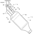
図1は前記多気筒エンジンの排気装置を備えたエンジンシステム100の概略構成図である。このエンジンシステム100は、シリンダヘッド9およびシリンダブロックを有するエンジン本体1と、エンジン制御用のECU2と、エンジン本体1に接続される排気マニホールド5と、排気マニホールド5に接続される触媒装置6とを備えている。
FIG. 1 is a schematic configuration diagram of an
前記シリンダヘッド9およびシリンダブロックの内部にはピストンがそれぞれ嵌挿された複数の気筒12が形成されている。本実施形態では、4つの気筒12、具体的には、図1の右から順に第1気筒12a,第2気筒12b,第3気筒12c,第4気筒12dが形成されている。前記シリンダヘッド9には、ピストンの上方に区画された燃焼室内に臨むようにそれぞれ点火プラグ15が設置されている。
A plurality of
前記エンジン本体1は4サイクルエンジンであって、図6に示すように、各気筒12a〜12dにおいて、180℃Aずつずれたタイミングで前記点火プラグ15による点火が行われ、吸気行程、圧縮行程、膨張行程、排気行程がそれぞれ180℃Aずつずれるように構成されている。本実施形態では、第1気筒12a→第3気筒12c→第4気筒12d→第2気筒12bの順に点火が行われてこの順に排気行程等が実施される。
The engine body 1 is a four-cycle engine. As shown in FIG. 6, in each of the
各気筒12の上部には、それぞれ燃焼室に向かって開口する2つの吸気ポート17および2つの排気ポート18が設けられている。吸気ポート17は、各気筒12内に吸気を導入するためのものである。排気ポート18は、各気筒12内から排気を排出するためのものである。各吸気ポート17には、これら吸気ポート17を開閉して吸気ポート17と気筒12内部とを連通あるいは遮断するための吸気バルブ19が設けられている。各排気ポート18には、これら排気ポート18を開閉してこれら排気ポート18と気筒12内部とを連通あるいは遮断するための排気バルブ20が設けられている。前記吸気バルブ19は吸気バルブ駆動機構(バルブ駆動手段)30により駆動されることで、所定のタイミングで吸気ポート17を開閉する。また、前記排気バルブ20は、排気バルブ駆動機構(バルブ駆動手段)40により駆動されて、所定のタイミングで排気ポート18を開閉する。
Two
前記吸気バルブ駆動機構30は、吸気バルブ19に連結された吸気カムシャフト31と吸気VVT(吸気バルブタイミング可変機構)32とを有している。吸気カムシャフト31は、周知のチェーン/スプロケット機構等の動力伝達機構を介してクランクシャフトに連結されており、クランクシャフトの回転に伴い回転して、吸気バルブ19を開閉駆動する。
The intake
前記吸気VVT32は、吸気バルブ19のバルブタイミングを変更するためのものである。この吸気VVT32は、吸気カムシャフト31と同軸に配置されてクランクシャフトにより直接駆動される所定の被駆動軸と吸気カムシャフト31との間の位相差を変更して、これによりクランクシャフトと前記吸気カムシャフト31との間の位相差を変更することで、吸気バルブ19のバルブタイミングを変更する。吸気VVT32の具体的構成としては、例えば、前記被駆動軸と前記吸気カムシャフト31との間に周方向に並ぶ複数の液室を有し、これら液室間に圧力差を設けることで前記位相差を変更する液圧式機構や、前記被駆動軸と前記吸気カムシャフト31との間に設けられた電磁石を有し、前記電磁石に電力を付与することで前記位相差を変更する電磁式機構等が挙げられる。この吸気VVT32は、ECU2で算出された吸気バルブ19の目標バルブタイミングに基づいて前記位相差を変更する。
The
前記排気バルブ駆動機構40は、前記吸気バルブ駆動機構30と同様の構造を有している。すなわち、排気バルブ駆動機構40は、排気バルブ20およびクランクシャフトに連結された排気カムシャフト41と、この排気カムシャフト41とクランクシャフトとの位相差を変更することで排気バルブ20のバルブタイミングを変更する排気VVT(排気バルブタイミング可変機構)42とを有している。排気VVT42は、ECU2で算出された排気バルブ20の目標バルブタイミングに基づいて、前記位相差を変更する。そして、排気カムシャフト41は、この位相差の下でクランクシャフトの回転に伴って回転して排気バルブ20を前記目標バルブタイミングで開閉駆動する。
The exhaust
なお、本実施形態では、前記吸気VVT32および排気VVT42は、吸気バルブ19および排気バルブ20の開弁期間及びリフト量つまりバルブ・プロファイルをそれぞれ一定に保ったまま、吸気バルブ19および排気バルブ20の開弁時期と閉弁時期とをそれぞれ変更する。
In the present embodiment, the
前記各気筒12の排気ポート18は、その下流側において独立排気通路52に接続されている。前記気筒12のうち第1気筒12aの排気ポート18と第4気筒12dの排気ポート18とは、それぞれ個別に、独立排気通路52a、52dに接続されている。一方、排気行程が隣り合わず排気順序が連続しない第2気筒12bと第3気筒12cの排気ポート18は、1つの独立排気通路52bに接続されている。これら独立排気通路52は互いに独立しており、第2気筒12bあるいは第3気筒12cから排出された排気と、第1気筒12aから排出された排気と、第4気筒12dから排出された排気とは、互いに独立して各独立排気通路52内を通って下流側に排出される。本実施形態では、これら独立排気通路52の上流部分は前記シリンダヘッド9内に形成されており、これら独立排気通路52の下流部分は前記排気マニホールド5に設けられている。
The
前記排気マニホールド5は、前述のように前記排気ポート18に接続される3つの独立排気通路52に加えて、3つの流路面積可変バルブ58と、低速側集合部56とを備えている。
In addition to the three
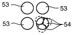
前記独立排気通路52は、その下流側、本実施形態では前記排気マニホールド5の上流端付近、において、それぞれ高速側通路53と低速側通路54とに分離している。図2および図3に示すように、高速側通路53は、それぞれシリンダヘッド9に形成された独立排気通路52の上流側部分から直線的に後方に延びた後、下方に湾曲する形状を有している。前記低速側通路54は、前記排気マニホールド5の上流端付近から下方に湾曲した後、高速側通路53の下方を通り、これら高速側通路53と同様に直線的に後方に延びた後、下方に湾曲する形状を有している。
The
前記各高速側通路53の断面積すなわち流路面積は互いに同一に設定されている。各低速側通路54の断面積すなわち流路面積は、互いに同一に設定されている。また、各高速側通路53の流路面積は低速側通路54の流路面積よりも大きく設定されている。
The cross-sectional areas of the high-
前記流路面積可変バルブ58は、前記各高速側通路53の流路面積を変更し、これにより各独立排気通路52の流路面積を変更するためのものである。これら流路面積可変バルブ58は各高速側通路53内にそれぞれ1つずつ設けられている。本実施形態では、これら流路面積可変バルブ58は、高速側通路53内の上流端付近であって高速側通路53内と低速側通路54とが分離する付近に設けられている。
The flow passage area
前記流路面積可変バルブ58は、その中央に設けられた回動軸58aが回動駆動されるに伴いこの回動軸58aを中心として回動する。本実施形態では、各流路面積可変バルブ58に、共通の回動軸58aが固定されており、3つの流路面積可変バルブ58は一体に回動する。各流路面積可変バルブ58は、排気の流れ方向と略平行な方向に広がる全開位置(図3の破線)と、排気の流れ方向と略垂直な方向に広がる全閉位置(図3の実線)との間で回動し、高速側通路53を開閉して高速側通路53の流路面積を変更する。なお、図3では、流路面積可変バルブ58の全開位置と全閉位置とをより明確に示すために、高速側通路53内に配置されて破線で示されるべき流路面積可変バルブ58を全閉位置にある状態で実線で示している。
The flow path area
前記回動軸58aは、その端部に設けられたバルブアクチュエータ(流路面積可変バルブ駆動手段)58bにより回動駆動される。このバルブアクチュエータ58bは、ECU2で算出された流路面積可変バルブ58の目標開度に応じて、前記回動軸58aを回動させて流路面積可変バルブ58を全閉あるいは全開位置に駆動する。このバルブアクチュエータ58bは前記回動軸58aを回動駆動して前記流路面積可変バルブ58を回動可能なものであればどのようなものであってもよい。
The
前記低速側集合部56は、前記低速側通路54の下流側に設けられる部分である。この低速側集合部56は、各低速側通路54と連通した状態で各低速側通路54の下流端に接続されている。各低速側通路54を通過したガスは、この低速側集合部56に流入してこの低速側集合部56にて集合する。この低速側集合部56において、前記3つの低速側通路54の下流端は互いに隣接する位置に配置されている。
The low speed
前記低速側集合部56は、略円筒状であってその上流端の断面は略円形を有している。各低速側通路54は、上流側では断面がそれぞれ略円形であって略円筒状をなす一方、下流端付近55では断面が円形から下流に向かうに従って徐々に扇形となっている。そして、これら低速側通路54は、扇形をなす各下流端が全体として略円形断面を形成するように集合して前記低速側集合部56の円形断面の上流端に接続されており、低速側集合部56の上流端の断面形状および断面積と3つの低速側通路54の下流端全体の断面形状および断面積とはほぼ同一に設定されている。すなわち、各通路の構成を模式的に示した図5において、3×A1(低速側通路54の下流端の断面積の合計)=S10(低速側集合部56の上流端の断面積)に設定されている。
The low-speed
前記低速側集合部56は、その上流端から下流に向かうに従って縮径してその断面積すなわち流路面積が下流に向かうに従って縮小する形状を有しており、低速側集合部56の下流端の断面積S11が上流端の断面積S10よりも小さく(S11<S10=3×A1)設定されている。このように流路面積が絞られるように構成された低速側集合部56には、各低速側通路54から高速で排気が流入する。
The low speed
前記低速側集合部56の下流端には前記触媒装置6の後述するケーシング62が接続されており、前記低速側通路54に流入した排気はこの低速側集合部56を高速で通過した後、前記ケーシング62内に流入する。
A casing 62 (described later) of the
前記触媒装置6は、エンジン本体1から排出された排気を浄化するための装置である。この触媒装置6は、三元触媒等の触媒本体64とこの触媒本体64を収容するケーシング62とを備えている。ケーシング62は、排気の流れ方向と平行に延びる略円筒状を有している。前記触媒本体64は、前記ケーシング62の下流部分に収容されており、このケーシング62の上流部分には、ケーシング62に流入したガスが混合可能な所定の空間が形成されている。
The
前記触媒装置6のケーシング62は、前記低速側集合部56および各高速側通路53と連通した状態でこれら低速側集合部56の下流端および各高速側通路53の下流端に接続されている。従って、前記低速側集合部56を通過した排気および各高速側通路53を通過した排気は、このケーシング62に流入してこのケーシング62の上流部分にて集合する。
The
このように、本実施形態では、触媒装置6のケーシング62の上流部分62aが、各独立排気通路を通過したガスが集合する集合部として機能する。そして、前記低速側通路54に流入した排気は前記低速側集合部56に流入した後このケーシング62に流入する一方、高速側通路53に流入したガスは途中で集合することなくこのケーシング62に流入してこのケーシング62にて集合する。
Thus, in the present embodiment, the
本実施形態では、前記3つの高速側通路53は前記ケーシング62の上流端において互いに隣接する位置に配置されている。
In the present embodiment, the three high
前記ケーシング62の上流部分62aは、その上端の断面積S20が前記低速側集合部56の下流端の断面積S11および各高速側通路53の下流端の断面積A2の合計面積よりも大きく、かつ、その上流端から所定距離の間、下流に向かうに従って拡径する形状を有している。すなわち、図5において、3×A2+S11(高速側通路53の下流端の断面積A2の合計3×A2と低速側集合部56の下流端の断面積S11との和)>S20(ケーシング62の上流端の断面積)に設定されているとともに、S20<S21(ケーシング62の下流側の断面積)に設定されている。各高速側通路53を通過した排気は、このように断面積が大きく容積の大きいケーシング62に流入する。従って、各高速側通路53を通過する排気は、その背圧が小さく抑えられて排気抵抗が少ない状態で円滑にケーシング62内に流入する。
The
前記ECU2は、周知のマイクロコンピュータをベースとするコントローラであって、プログラムを実行するためのCPUと、RAMやROMからなりプログラム及びデータを格納するメモリと、各種信号の入出力を行なうI/Oバスとを備えている。このECU2は、前記I/Oバスを介して各種センサからの信号を受け、この信号に基づき種々の演算を行う。 The ECU 2 is a controller based on a known microcomputer, and includes a CPU for executing a program, a memory including a RAM and a ROM for storing a program and data, and an I / O for inputting and outputting various signals. It has a bus. The ECU 2 receives signals from various sensors via the I / O bus and performs various calculations based on the signals.
ECU2は、運転条件に応じて、吸気バルブ19および排気バルブ20の目標バルブタイミングを演算するとともに、前記流路面積可変バルブ58の目標開度を演算して、吸気バルブ19および排気バルブ20のバルブタイミング、流路面積可変バルブ58の開度がこれら目標値になるように、吸気VVT32および排気VVT42、前記バルブアクチュエータ58bを駆動する。
The ECU 2 calculates target valve timings of the
前記吸気バルブ19および排気バルブ20の目標バルブタイミングは、エンジンの回転数NEが基準回転数N1より低い低速領域R1(図8参照)において、図6に示すように、吸気バルブ19と排気バルブ20の両方が排気上死点(TDC)を挟んで所定のオーバーラップ期間T_O/L開弁して排気バルブ20の開弁期間と吸気バルブ19の開弁期間とがオーバーラップするように、かつ、排気バルブ20が排気行程が連続する他の気筒12の前記オーバーラップ期間T_O/L中に開弁を開始するように設定されている。具体的には、第1気筒12aの吸気バルブ19と排気バルブ20とがオーバーラップしている期間中に第3気筒12cの排気バルブ20が開弁を開始し、第3気筒12cの吸気バルブ19と排気バルブ20とがオーバーラップしている期間中に第4気筒12dの排気バルブ20が開弁を開始し、第4気筒12dの吸気バルブ19と排気バルブ20とがオーバーラップしている期間中に第2気筒12bの排気バルブ20が開弁を開始し、第2気筒12bの吸気バルブ19と排気バルブ20とがオーバーラップしている期間中に第1気筒12aの排気バルブ20が開弁を開始するよう設定されている。
The target valve timings of the
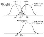
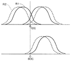
また、前記低速領域R1における前記排気バルブ20および吸気バルブ19の目標バルブタイミングは、図7に示すように、オーバーラップ期間T_O/L中において、排気バルブ20と吸気バルブ19のバルブリフトカーブの重複する領域の面積が排気上死点TDCよりも遅角側の方が排気上死点よりも進角側よりも大きくなるように設定されている。すなわち、排気上死点TDCから排気バルブ20の閉弁時期EVCまでの期間における排気バルブ20と吸気バルブ19のうちバルブリフトの小さい方のバルブ(図7では、角度C1までは吸気バルブ19であり、C1以降は排気バルブ20である)のバルブリフトの時間面積S_VL2が、吸気バルブ19の開弁時期IVOから排気上死点TDCまでの期間における排気バルブ20と吸気バルブ19のうちバルブリフトの小さい方のバルブ(図7では吸気バルブ19)のバルブリフトの時間面積S_VL1よりも大きくなるように設定されている。
Further, the target valve timings of the
前記オーバーラップ期間の掃気時において、吸気ポート17から吸気バルブ19を介して気筒12内に吸気が流入して気筒12内から排気バルブ20を介して排気ポート18側に残留ガスが流出するというガス流れでは、掃気されるガス量は排気バルブ20と吸気バルブ19のうちバルブリフトの小さい方のバルブの開口量によって制約される。これに対して、本エンジンシステム100では、前記のように、排気上死点TDCよりも遅角側において、吸気バルブ19と排気バルブ20のうちバルブリフトの小さい方のバルブのバルブリフトの時間面積S_VL2がより大きく設定されてこのバルブ開口量が大きく確保されており、排気上死点TDCよりも遅角側において重点的に掃気が行なわれる。
During scavenging during the overlap period, the intake air flows into the
前記低速領域R1では、前記S_VL2>S_VL1の関係が維持されつつ、図8に示すように、排気バルブ20の目標バルブタイミング(開弁時期EVOおよび閉弁時期EVC)はエンジン回転数NEが高くなるほど進角側に設定されている。また、図9に示すように、吸気バルブ19の目標バルブタイミング(開弁時期IVOおよび閉弁時期IVC)はエンジン回転数NEが高くなるほど遅角側に設定されている。そして、低速領域R1では、エンジンの回転数NEが高くなるほど前記オーバーラップ期間T_O/Lが小さくなるように設定されている。
In the low speed region R1, the relationship of S_VL2> S_VL1 is maintained, and the target valve timing (opening timing EVO and closing timing EVC) of the
前記基準回転数N1は、例えば、2000rpmである。また、排気バルブ20の開弁時期EVOおよび閉弁時期EVCは、例えば、2000rpmにおいてEVO=BBDC(下死点前)30℃A、EVC=ATDC(上死点後)30℃Aに設定され、1500rpm以下においてEVO=BBDC20℃A、EVC=ATDC40℃Aに設定されている。吸気バルブ19の開弁時期IVOおよび閉弁時期IVCは、例えば、2000rpmにおいてIVO=BTDC(上死点前)30℃A、IVC=50℃Aに設定され、1500rpm以下においてIVO=BTDC40℃A、IVC=40℃Aに設定されて、前記オーバーラップ期間T_O/Lは、2000rpmにおいて60℃A、1500rpm以下において80℃Aに設定されている。
The reference rotation speed N1 is, for example, 2000 rpm. Further, the valve opening timing EVO and the valve closing timing EVC of the
なお、エンジンの回転数NEと前記オーバーラップ期間T_O/Lの関係は、エンジンの回転数NEが高い条件の方がエンジンの回転数NEが低い条件に比べてオーバーラップ期間T_O/Lが小さく設定されていればよく、エンジンの回転数NEに応じてオーバーラップ期間T_O/Lが連続的に変化するものでなくてもよい。 The relationship between the engine speed NE and the overlap period T_O / L is set such that the overlap period T_O / L is smaller when the engine speed NE is higher than when the engine speed NE is low. The overlap period T_O / L does not have to change continuously according to the engine speed NE.
一方、エンジン回転数NEが前記基準回転数N1以上の高速領域R2では、排気バルブ20の目標バルブタイミングは前記低速領域R1よりも進角側に設定されている。また、高速領域R2では、吸気バルブ19の目標バルブタイミングは前記低速領域R1よりも遅角側に設定されている。そして、高速領域R2では、排気バルブ20と吸気バルブ19オーバーラップ期間T_O/Lが低速領域R1での値よりも小さく設定されている。例えば、高速領域R2ではオーバーラップ期間T_O/Lは40℃A以下に設定されている。
On the other hand, in the high speed region R2 where the engine rotational speed NE is equal to or higher than the reference rotational speed N1, the target valve timing of the
なお、高速領域R2においても、排気バルブ20の目標バルブタイミングはエンジン回転数NEが高くなるほど進角側に設定され、吸気バルブ19の目標バルブタイミングはエンジン回転数NEが高くなるほど遅角側に設定されている。
Even in the high speed region R2, the target valve timing of the
図10に、低速領域R1とR2における排気バルブ20および吸気バルブ19の目標バルブタイミングを比較したものを示す。この図10において、実線が低速領域R1での目標バルブタイミングであり、破線が高速領域R2での目標バルブタイミングである。
FIG. 10 shows a comparison of target valve timings of the
前述のように、排気バルブ20の目標バルブタイミングはエンジン回転数NEが低いほど遅角されており、全ての運転領域で下死点より前で開弁するよう設定された排気バルブ20は、低速領域R1において、より下死点に近く他の気筒の上死点により近い時期で開弁する。
As described above, the target valve timing of the
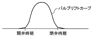
なお、本エンジンシステム100において、前記吸気バルブ19および排気バルブ20の開弁時期、閉弁時期とは、それぞれ、図12に示すように、各バルブのリフトカーブにおいてバルブのリフトが急峻に立ち上がるあるいは立ち下がる時期であり、例えば0.4mmリフトの時期をいう。
In the
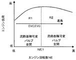
前記流路面積可変バルブ58の目標開度は、前記低速領域R1において全閉に設定される一方、高速領域R2において全開に設定されている。低速領域R1では、前記各高速側通路53が遮断されて、エンジン本体1から排出された排気は前記低速側通路54のみを通って下流に流れる。一方、高速領域R2では、各高速側通路53が開放されて、エンジン本体1から排出された排気は高速側通路53および低速側通路54を通って下流に流れる。
The target opening degree of the flow path area
以上のように構成されたエンジンシステム100における吸気性能について次に説明する。
Next, the intake performance in the
所定の気筒12(以下、適宜、排気行程気筒12という)の排気バルブ20が開弁すると、この気筒12の排気ポート18からこの気筒12に対応する前記独立排気通路52に排気が高速で流入する。
When an
前記低速領域R1では、前記高速側通路53は遮断されて独立排気通路52のうち低速側通路54のみが開放されており、前記排気は前記低速側通路54にのみ流入する。前述のように、この低速側通路54の流路面積は独立排気通路52の上流側部分さらには高速側通路53よりも小さく設定されている。さらに、低速側通路54の下流に設けられた前記低速側集合部56は、下流に向かうほど流路面積が小さくなっている。従って、前記排気は、前記低速側集合部56を高速で通過する。
In the low speed region R 1, the high
このようにして、低速側集合部56に所定の低速側通路54から高速の排気が噴出されると、この排気の周囲に発生した負圧作用すなわちエゼクタ効果により低速側集合部56に連通している他の低速側通路54には、その内部のガスを下流側へと吸い出す力が作用する。前記排気行程気筒12の排気バルブ20の開弁時において、排気順序がこの排気行程気筒12の1つ前に設定された他の気筒12(以下、適宜、吸気行程気筒12という)は前記オーバーラップ期間中にあり、その排気バルブ20と吸気バルブ19とはいずれも開弁している。そのため、前記吸出し力は、この吸気行程気筒12に接続された低速側通路54を介して吸気行程気筒12内のガスに作用する。この吸出し力により吸気行程気筒12内の残留ガスは気筒12内から勢いよく吸い出される。
Thus, when high-speed exhaust gas is ejected from the predetermined low-
ここで、排気上死点よりも遅角側では、ピストンの下降に伴い燃焼室の容積が増大することで、吸気ポート17内のガスに吸気行程気筒12内への強い吸引力が作用する。前述のように、本エンジンシステム100では、排気上死点よりも遅角側において、吸気バルブ19と排気バルブ20のうちバルブリフトの小さい方のバルブのバルブリフトの時間面積S_VL2がより大きく設定されており、排気上死点よりも遅角側であって吸気ポート17内のガスに吸気行程気筒12内への強い吸引力が作用するタイミングで重点的に掃気が行なわれている。そのため、この吸気に加えられる気筒12内への吸引力と、前記エゼクタ効果により気筒12内の残留ガスに加えられる排気ポート18側への吸出し力とが効果的に作用して、より多くのガスが掃気され、より多くの吸気が気筒12内に流入する。
Here, on the retard side from the exhaust top dead center, the volume of the combustion chamber increases as the piston descends, so that a strong suction force into the
特に、前記低速領域R1では、排気バルブ20は下死点付近であって吸気行程気筒12の排気上死点付近において開弁している。そのため、前記吸気行程気筒12では、前記ピストンの下降に伴って吸気ポート17側の吸気に気筒12内への吸引力が作用するのと同時に、排気バルブ20の開弁直後に気筒12内から排出される高速のガス(いわゆるブローダウンガス)により生成される高い吸出し力が作用する。これにより、前記残留ガスはより勢いよく排出されてより多量の吸気が気筒12内に流入する。
In particular, in the low speed region R1, the
このようにして、本エンジンシステム100では、低速領域R1において、エゼクタ効果が効果的に発揮され各気筒12の掃気が促進されて、吸気効率が高められ、エンジン出力が高められる。
Thus, in the
ここで、エンジン回転数NEが高くなると吸気慣性により気筒12に吸気が流入するタイミングは遅角側に移行する。すなわち、気筒12に流入する吸気量が最大となる時期は遅角側に移行する。これに対して、前記低速領域R1において、吸気バルブ19の閉弁時期IVCは、エンジン回転数NEが高くなるほど遅角されている。そのため、この低速領域R1では、前記エゼクタ効果により掃気が促進されるとともに、エンジン回転数NEの変化に伴う吸気量の流入タイミングの変化に対応してより多くの吸気量が気筒12内に流入する。
Here, when the engine speed NE increases, the timing at which the intake air flows into the
また、エンジン回転数NEが高く排気行程の時間が短いほど、排気バルブ20を早期に開弁する方がより多くの排気を排出することができる。これに対して、前記低速領域R1において、排気バルブ20の開弁時期EVOは、エンジン回転数NEが高くなるほど進角されている。そのため、この低速領域R1では、前記エゼクタ効果により掃気が促進されるとともに、エンジン回転数NEの変化に対応してより多くの排気が排出される。
Further, as the engine speed NE is higher and the exhaust stroke time is shorter, more exhaust can be discharged by opening the
一方、高速領域R2では、高速側通路53は開放されており、気筒12の排気ポート18から独立排気通路52に流入した排気は、前記低速側通路54に加えて高速側通路53に流入する。前述のように、高速側通路53の流路面積は低速側通路54の流路面積よりも大きく設定されており、前記排気の多くはこの高速側通路53を通過する。そして、高速側通路53を通過した排気は、直接前記触媒装置6のケーシング62に流入する。ここで、これら高速側通路53を通過したガスが集合するこのケーシング62の上流部分62aは、その流路面積が各高速側通路53の下流端の合計面積よりも大きく設定されているとともに、下流に向かうほど拡径する形状を有している。そのため、各高速側通路53を通過した排気は、より少ない抵抗でこの高速側通路53を円滑に通過する。これに伴い、高速側通路53の下流端の圧力すなわち各高速側通路53の背圧は低く抑えられる。
On the other hand, in the high speed region R <b> 2, the high
このようにして、本エンジンシステム100では、排気流量が大きく背圧が高くなりやすい高速領域R2では、高速側通路53が開放されて排気が抵抗の少ない状態で排出されることでシリンダの掃気が促進されてエンジン出力が確保される。
In this way, in the
また、この高速領域R2において、吸気バルブ19の閉弁時期IVCは、エンジン回転数NEが高くなるほど遅角されており、前述のようにエンジン回転数NEが高くなるほど遅角側に移行する吸気量が最大となる時期に合わせて吸気バルブ19が閉弁するため、エンジン回転数NEに応じて適切に吸気量が確保される。そして、この高速領域R2において、排気バルブ20の開弁時期EVOはエンジン回転数NEが高くなるほど進角されており、気筒12からはエンジン回転数NEの変化に対応してより多くの排気が排出される。
Further, in the high speed region R2, the closing timing IVC of the
ここで、前記実施形態では、前記吸気バルブ19がその開弁期間及びリフト量つまりバルブ・プロファイルが一定に保たれたまま、その開弁時期と閉弁時期とが変更される場合について説明したが、吸気バルブタイミング可変機構として、吸気バルブ19の開弁時期を一定時期に固定しつつバルブリフト量を変更することで閉弁時期を変更するものを用いてもよい。
Here, in the above-described embodiment, the case where the valve opening timing and the valve closing timing of the
この場合には、前記低速領域R1において、図11に示すように、エンジンに対する要求トルクすなわちエンジン負荷が高くなるほど吸気バルブ19のバルブリフト量を大きくするのが好ましい。このようにすれば、吸気バルブ19の開弁時期IVOが固定されることで前記オーバーラップ期間が十分に確保されて前記エゼクタ効果による掃気性能が高く維持されるとともに、高負荷領域において吸気バルブ19のバルブリフト量が大きくなるのに伴い吸気量が増大することでエンジン出力が確実に高められる。一方、低負荷領域では、図11に示すように、吸気バルブ19の閉弁時期がエンジン負荷の低下に伴いBDCより進角側に移動することで、ポンピングロスが低減され、燃焼安定性が向上する。
In this case, in the low speed region R1, as shown in FIG. 11, it is preferable to increase the valve lift amount of the
また、吸気バルブタイミング可変機構として、吸気バルブ19の開弁時期、閉弁時期、バルブリフト量を、それぞれ個別に変更することができるものを用いてもよい。
Further, as the intake valve timing variable mechanism, a mechanism capable of individually changing the valve opening timing, the valve closing timing, and the valve lift amount of the
また、前記低速領域R1において、前記オーバーラップ期間をエンジン回転数NEによらず一定としてもよい。 In the low speed region R1, the overlap period may be constant regardless of the engine speed NE.
また、前記実施形態では前記低速領域R1において前記流路面積可変バルブ58が全閉位置に駆動される場合について説明したが、この低速領域R1における流路面積可変バルブ58の位置は全閉位置に限らず、全開位置よりも閉じ側、すなわち、高速側通路53の流路面積が最大面積よりも縮小される位置であればよい。
In the above embodiment, the flow area
また、低速領域R1において、前記流路面積可変バルブ58を全開位置と全閉位置との間で段階的あるいは連続的に変化するようにしてもよい。この場合には、エンジン回転数NEが高くなるほど高速側通路53の流路面積が大きくなるように前記流路面積可変バルブ58を駆動するのが好ましい。このようにすれば、エンジン回転数NEが低く排気の流量が少ない領域では高速側通路53の流路面積を絞ることでエゼクタ効果により掃気性能を高めることができる一方、エンジン回転数NEが高く排気の流量が多い領域では高速側通路の流路面積を大きくすることで排気抵抗を小さく抑えることにより掃気を促進することができる。
In the low speed region R1, the flow path area
また、前記実施形態では、前記各独立排気通路52が低速側通路54と高速側通路53とに分離しており、流路面積可変バルブ58が高速側通路53を開閉することで独立排気通路52の流路面積が変更される場合について示したが、独立排気通路52の流路面積を変更するための構成はこれに限らない。例えば、独立排気通路52を低速側通路54と高速側通路53とに分離せず、独立排気通路52内にその流路面積を変更可能な流路面積可変バルブを設けてもよい。
Further, in the above embodiment, each of the
また、触媒装置6の位置は前記に限らない。例えば、前記独立排気通路52の下流端と触媒装置6との間に、所定の通路を設けて、この通路内において高速側通路53を通過したガスが集合するようにしてもよい。ただし、本エンジンシステム100によれば、エゼクタ効果により吸気効率を高めることができるため、ターボ過給機を有しないエンジンシステムにおいて有用である。そして、このようにターボ過給機を有しない場合には、触媒装置6を前記実施形態のように各独立排気通路53に直接接続してより上流側の位置に配置することができ、これにより触媒本体64に流入する排気の温度を高く維持して触媒を早期に活性させることができる。
Further, the position of the
また、低速領域R1のうちエンジン負荷の低い低負荷領域では、吸気の圧力が小さく、吸気バルブ19と排気バルブ20のオーバーラップ期間を大きくすると排気が吸気側に逆流するおそれがあるため、このような場合には、吸気バルブ19と排気バルブ20のオーバーラップ期間を小さくするとともに、流路面積可変バルブ58を全開としてもよい。
Further, in the low load region where the engine load is low in the low speed region R1, the pressure of the intake air is small, and if the overlap period of the
1 エンジン本体
5 排気マニホールド
17 吸気ポート
18 排気ポート
19 吸気バルブ
20 排気バルブ
30 吸気バルブ駆動機構(バルブ駆動手段)
32 吸気VVT(吸気バルブタイミング可変機構)
40 排気バルブ駆動機構(バルブ駆動手段)
42 排気VVT(排気バルブタイミング可変機構)
52 独立排気通路
58 流路面積可変バルブ
58b バルブアクチュエータ(流路面積可変バルブ駆動手段)
62a ケーシング上流部分(集合部)
DESCRIPTION OF SYMBOLS 1 Engine
32 Intake VVT (Intake valve timing variable mechanism)
40 Exhaust valve drive mechanism (valve drive means)
42 Exhaust VVT (Exhaust valve timing variable mechanism)
52
62a Casing upstream part (aggregation part)
Claims (4)
1つの気筒あるいは排気順序が互いに連続しない複数の気筒の排気ポートにそれぞれ接続される独立排気通路と、
前記各独立排気通路の下流端に接続されて、当該各独立排気通路を通過するガスが集合する集合部と、
前記集合部の上流側に設けられて、前記各独立排気通路の流路面積を変更可能な流路面積可変バルブと、
前記流路面積可変バルブを駆動可能な流路面積可変バルブ駆動手段と、
前記各気筒の吸気バルブおよび排気バルブを駆動可能なバルブ駆動手段とを備え、
前記流路面積可変バルブ駆動手段は、エンジンの回転数が予め設定された基準回転数よりも低い低速領域において、少なくともエンジンに対する要求トルクが高い高負荷領域では、前記各独立排気通路の流路面積が最大面積よりも小さくなるように前記流路面積可変バルブを駆動し、
前記バルブ駆動手段は、前記低速領域の少なくとも前記高負荷領域において、前記各気筒の吸気バルブの開弁期間と排気バルブの開弁期間とが所定のオーバーラップ期間重複するとともに、排気順序が連続する気筒間において一方の気筒の前記オーバーラップ期間中に他方の気筒の排気バルブが開弁するように、かつ、排気上死点から前記排気バルブの閉弁時期までの期間における前記吸気バルブと前記排気バルブのうちバルブリフトの小さい方のバルブのバルブリフトの時間面積の方が、前記吸気バルブの開弁時期から排気上死点までの前記吸気バルブと前記排気バルブのうちバルブリフトの小さい方のバルブのバルブリフトの時間面積よりも大きくなるように、前記各気筒の吸気バルブおよび排気バルブを駆動することを特徴とする多気筒エンジンの排気装置。 An exhaust system for a multi-cylinder engine having a plurality of cylinders each having an intake port and an exhaust port, and having an intake valve capable of opening and closing the intake port and an exhaust valve capable of opening and closing the exhaust port,
An independent exhaust passage connected to exhaust ports of one cylinder or a plurality of cylinders whose exhaust sequences are not continuous with each other;
A collecting portion connected to the downstream end of each independent exhaust passage, where gas passing through each independent exhaust passage gathers;
A variable flow area valve provided on the upstream side of the collecting portion and capable of changing the flow area of each independent exhaust passage;
A flow path area variable valve driving means capable of driving the flow path area variable valve;
Valve drive means capable of driving the intake valve and the exhaust valve of each cylinder,
The flow path area variable valve driving means is configured such that the flow area of each independent exhaust passage is at least in a high load area where the required torque for the engine is high in a low speed area where the engine speed is lower than a preset reference speed. The flow path area variable valve is driven so that is smaller than the maximum area,
In the valve driving means, in at least the high load region of the low speed region, the valve opening period of the intake valve and the valve opening period of the exhaust valve of each cylinder overlap with each other by a predetermined overlap period, and the exhaust sequence continues. The intake valve and the exhaust gas in the period from the exhaust top dead center to the closing timing of the exhaust valve so that the exhaust valve of the other cylinder opens during the overlap period of one cylinder between the cylinders The valve lift time area of the valve with the smaller valve lift is the valve with the smaller valve lift of the intake valve and the exhaust valve from the opening timing of the intake valve to the exhaust top dead center. The intake valve and the exhaust valve of each cylinder are driven so as to be larger than the valve lift time area. Exhaust system of the engine.
前記バルブ駆動手段は、前記排気バルブの開弁期間を一定に保持しつつ当該排気バルブの開弁時期および閉弁時期を変更可能な排気バルブタイミング可変機構を備え、
前記排気バルブタイミング可変機構は、前記低速領域の少なくとも前記高負荷領域において、前記オーバーラップ期間がエンジンの回転数が前記基準回転数よりも高い高速領域よりも大きくなるように、前記排気バルブの開弁時期および閉弁時期を前記高速領域よりも遅角させることを特徴とする多気筒エンジンの排気装置。 An exhaust system for a multi-cylinder engine according to claim 1,
The valve driving means includes an exhaust valve timing variable mechanism capable of changing a valve opening timing and a valve closing timing of the exhaust valve while maintaining a constant valve opening period of the exhaust valve,
The exhaust valve timing variable mechanism opens the exhaust valve so that the overlap period is larger than that in the high speed region where the engine speed is higher than the reference speed in at least the high load region of the low speed region. An exhaust system for a multi-cylinder engine, wherein the valve timing and the valve closing timing are retarded from the high speed region.
前記バルブ駆動手段は、前記吸気バルブのバルブリフト量を変化させることで当該吸気バルブの閉弁時期を変更可能な吸気バルブタイミング可変機構を備え、
前記吸気バルブタイミング可変機構は、前記低速領域の少なくとも前記高負荷領域において、エンジンに対する要求トルクが高いほど前記吸気バルブのバルブリフト量を大きくすることを特徴とする多気筒エンジンの排気装置。 An exhaust system for a multi-cylinder engine according to claim 1 or 2,
The valve driving means includes an intake valve timing variable mechanism capable of changing a valve closing timing of the intake valve by changing a valve lift amount of the intake valve,
The exhaust device for a multi-cylinder engine, wherein the intake valve timing variable mechanism increases the valve lift amount of the intake valve as the required torque for the engine increases in at least the high load region of the low speed region.
前記バルブ駆動手段は、前記吸気バルブの開弁期間を一定期間に保持しつつ当該吸気バルブの開弁時期および閉弁時期を変更可能な吸気バルブタイミング可変機構を備え、
前記吸気バルブタイミング可変機構は、前記低速領域の少なくとも前記高負荷領域において、前記オーバーラップ期間が前記高速領域よりも大きくなるように、前記吸気バルブの開弁時期および閉弁時期を前記高速領域よりも進角させることを特徴とする多気筒エンジンの排気装置。 An exhaust system for a multi-cylinder engine according to claim 2,
The valve driving means includes an intake valve timing variable mechanism capable of changing a valve opening timing and a valve closing timing of the intake valve while maintaining a valve opening period of the intake valve at a certain period.
The intake valve timing variable mechanism is configured to set the valve opening timing and the valve closing timing of the intake valve from the high speed region so that the overlap period is larger than the high speed region in at least the high load region of the low speed region. The multi-cylinder engine exhaust system is also characterized by being advanced.
Priority Applications (1)
| Application Number | Priority Date | Filing Date | Title |
|---|---|---|---|
| JP2010080143A JP5407992B2 (en) | 2010-03-31 | 2010-03-31 | Exhaust system for multi-cylinder engine |
Applications Claiming Priority (1)
| Application Number | Priority Date | Filing Date | Title |
|---|---|---|---|
| JP2010080143A JP5407992B2 (en) | 2010-03-31 | 2010-03-31 | Exhaust system for multi-cylinder engine |
Publications (2)
| Publication Number | Publication Date |
|---|---|
| JP2011214403A JP2011214403A (en) | 2011-10-27 |
| JP5407992B2 true JP5407992B2 (en) | 2014-02-05 |
Family
ID=44944412
Family Applications (1)
| Application Number | Title | Priority Date | Filing Date |
|---|---|---|---|
| JP2010080143A Active JP5407992B2 (en) | 2010-03-31 | 2010-03-31 | Exhaust system for multi-cylinder engine |
Country Status (1)
| Country | Link |
|---|---|
| JP (1) | JP5407992B2 (en) |
Families Citing this family (1)
| Publication number | Priority date | Publication date | Assignee | Title |
|---|---|---|---|---|
| KR101566740B1 (en) | 2013-12-19 | 2015-11-06 | 현대자동차 주식회사 | Control Apparatus of Engine having Variable Valve Lift and Method Thereof |
Family Cites Families (4)
| Publication number | Priority date | Publication date | Assignee | Title |
|---|---|---|---|---|
| JP3678861B2 (en) * | 1996-12-18 | 2005-08-03 | ヤマハ発動機株式会社 | Engine operation control device |
| JP2004332561A (en) * | 2003-04-30 | 2004-11-25 | Mitsubishi Motors Corp | Exhaust emission control device for internal combustion engine |
| JP2006132371A (en) * | 2004-11-04 | 2006-05-25 | Yamaha Motor Co Ltd | Engine and vehicle provided with the same |
| JP4807343B2 (en) * | 2007-10-12 | 2011-11-02 | マツダ株式会社 | Engine supercharger |
-
2010
- 2010-03-31 JP JP2010080143A patent/JP5407992B2/en active Active
Also Published As
| Publication number | Publication date |
|---|---|
| JP2011214403A (en) | 2011-10-27 |
Similar Documents
| Publication | Publication Date | Title |
|---|---|---|
| JP5515977B2 (en) | Exhaust system for multi-cylinder engine | |
| JP4993010B2 (en) | Spark ignition multi-cylinder engine | |
| JP4905591B2 (en) | High expansion ratio internal combustion engine | |
| JP5471720B2 (en) | Exhaust system for multi-cylinder engine | |
| JP4952732B2 (en) | Internal combustion engine control method and internal combustion engine control system | |
| JP5979031B2 (en) | Spark ignition engine | |
| JP4506414B2 (en) | Valve characteristic control device for internal combustion engine | |
| WO2016098768A1 (en) | Variable valve system and variable valve control device for internal combustion engine | |
| JP5515972B2 (en) | Exhaust system for multi-cylinder engine | |
| JP5531923B2 (en) | Intake and exhaust system for multi-cylinder engine | |
| JP5998503B2 (en) | Intake and exhaust system for multi-cylinder engine | |
| JP5851463B2 (en) | Valve timing control device for internal combustion engine | |
| JP5407992B2 (en) | Exhaust system for multi-cylinder engine | |
| JP5447095B2 (en) | Exhaust system for multi-cylinder engine | |
| JP5920237B2 (en) | Control device for spark ignition engine | |
| KR101558352B1 (en) | Engine having continuous varialbe valve timing device | |
| JP5472050B2 (en) | Exhaust system for multi-cylinder engine | |
| JP5794037B2 (en) | Intake and exhaust system for multi-cylinder engine | |
| JP2007278208A (en) | Control device for internal combustion engine | |
| JP5673214B2 (en) | Intake and exhaust system for multi-cylinder engine | |
| JP5531922B2 (en) | Intake and exhaust system for multi-cylinder engine | |
| JP5817302B2 (en) | Intake and exhaust system for multi-cylinder engine | |
| JP5759512B2 (en) | Control device for internal combustion engine | |
| JP5935754B2 (en) | Control device for internal combustion engine | |
| JP2009228614A (en) | Two stroke type internal combustion engine |
Legal Events
| Date | Code | Title | Description |
|---|---|---|---|
| A621 | Written request for application examination |
Free format text: JAPANESE INTERMEDIATE CODE: A621 Effective date: 20130118 |
|
| TRDD | Decision of grant or rejection written | ||
| A977 | Report on retrieval |
Free format text: JAPANESE INTERMEDIATE CODE: A971007 Effective date: 20130930 |
|
| A01 | Written decision to grant a patent or to grant a registration (utility model) |
Free format text: JAPANESE INTERMEDIATE CODE: A01 Effective date: 20131008 |
|
| A61 | First payment of annual fees (during grant procedure) |
Free format text: JAPANESE INTERMEDIATE CODE: A61 Effective date: 20131021 |
|
| R150 | Certificate of patent or registration of utility model |
Ref document number: 5407992 Country of ref document: JP Free format text: JAPANESE INTERMEDIATE CODE: R150 |